unit vi chemistry of advenced materials rev… · unit vi chemistry of advenced materials rev.ed ....
TRANSCRIPT

UNIT VI CHEMISTRY OF ADVENCED MATERIALS Rev.Ed. 2013-14
Engineering Chemistry Page 137
CHEMISTRY OF ADVANCED MATERIALS
Syllabus : Nano meterials (preparation of carbon nanotubes and fullerenes – properties of nano
materials – engineering applications) – Liquid crystals (Types – Application in LCD and
engineering applications) – Fiber reinforced plastics – Biodegradable polymers – Conducting
polymers – Solar cells (solar heaters – photo voltaic cells – solar reflectors – green house
concepts – Green chemistry (Methods for green synthesis and applications) – Cement –
Hardening and setting – Deterioration of cement concrete
Objectives: With the knowledge available now, future engineers should know at least some of
the advanced materials that are becoming available. Hence some of them are introduced here.
OUTLINES
Nanomaterials
Liquid crystals
Fiber reinforced plastics
Solar cells
Green House concepts
Green chemistry
Cement

UNIT VI CHEMISTRY OF ADVENCED MATERIALS Rev.Ed. 2013-14
Engineering Chemistry Page 138
1. Nano-materials
Nano-materials are nano powders or nano-crystalline materials or nano particles are novel materials,
whose molecular structures have been engineered at the nanometer scale in the order of 1-100 nm. A
nano-meter is one billionth (10-9
) of a meter. The significance of nano-materials is due to their small size.
They exhibit unique properties different from their bulk materials like melting point, electrical
conductivity, transparency, etc. They have increased surface area and quantum effects. These have
components of at least in one dimension. This changes the properties such as reactivity, strength, optical,
electrical and magnetic behaviour of metals. Nano materials are strong, hard, and ductile at high
temperatures, wear resistant, erosion and corrosion resistant.
A nano-particle is defined as a small object that behaves as a whole unit in terms of its transport and
other properties and exhibits a number of special properties relative to its bulk material. It is an object
with all the three dimensions on a nano-scale. Nano-materials can be biological, inorganic or organic
by their origin. Volcanic ash, carbon soot and incidental by products of welding and internal
combustion engines are examples of natural nano-particles.
Nanomaterials in one dimension are layers like thin films or surface coatings
Nanomaterials in two dimensions are tubes like nanotubes, fibres and nano wires
Nano particles in three dimensions are particles like precipitates, colloids and quantum dots.
1.1. Nanowires: One dimensional nano structures can control the density of states in a semiconductor,
which in turn control their electronic and optical properties. Hence nano-wires are employed in next
generation electronics, photonics, sensors and energy application. They allow the growth of an axial
hetero structure and provide the flexibility to create hetero structures, which allow integration of
compound semiconductor based opto-electronic devices with silicon based micro-electronics.
1.2. Quantum dots: A quantum dot is a particle having an approximate size of 1mm and has the
properties of a semiconductor. Silicon is the most popular material used in the creation of a quantum dot.
Quantum dots exhibit unusual properties, which are not present in usual semi conducting materials.
Electrons in general occupy one of the two bands in a crystal (valence band VB and conduction band,
CB). By proper excitation, the electron moves from VB to CB creating a hole in VB. The distance
between the electron and hole is called Excitation Bohr Radius. This gap can be reduced, if the size of
crystal is reduced. This increases the absorption of energy by crystal and crowds the gap. Hence these
have a unique application in various fields. Multiple quantum dots are used as LEDs in sign board
displays and cell staining for life science observations, as luminescent dust to track trespassers in
restricted areas and they are also used to transmit data, similar to fibre optics.

UNIT VI CHEMISTRY OF ADVENCED MATERIALS Rev.Ed. 2013-14
Engineering Chemistry Page 139
1.3.Carbon NanoTubes (CNT): Carbon nanotubes are allotropes of carbon with a nanostructure having
length to diameter ratio greater than 100,000. They are also called as Bucky tubes. These are long, thin
cylinders of carbon, discovered by S. Iijima in 1991.They are considered as a sheet of graphite rolled into
a cylinder. These have a broad range of electronic, thermal and structural properties depending on the
length, diameter, chirality or twist of nanotube.
1.4 Types of carbon nanotubes: Depending on the arrangement of atoms in carbon nanotubes, there
are two types of carbon nanotubes.
i) Single walled nanotubes (SWNT)
ii) Multi walled nanotubes (MWNT)
Single Walled Nano Tubes (SWNT)
Single walled nanotubes have a diameter close to 1nm and run into million times longer than its
diameter.
They are obtained by wrapping a sheet of graphene ( a single layer of graphite) into seamless
sheets.
There are three types of single walled nanotubes base on the way the graphene sheet is wrapped.
Graphene sheet is represented by a pair of indices (n, m) called the chiral vector. The integers n
and m denote the number of unit vectors along two directions in the honey comb crystal of
graphene.
If m=0, the nanotubes are zig-zig. The lines of the carbon bonds are down the centre.
If n=m, the nanotubes are called arm- chair. The lines of hexagons are parallel to the axis of the
nanotubes.
Otherwise, they are called ‘chiral’. They have a twist or spiral around the nanotubes.

UNIT VI CHEMISTRY OF ADVENCED MATERIALS Rev.Ed. 2013-14
Engineering Chemistry Page 140
Multi Walled Nano Tubes (MWNT):
Multi- walled nanotubes consist of multiple rolled concentric tubes of graphite.
The interlayer distance in multi-walled nanotubes is close to the distance between graphene
layers. In graphite it is approximately 3.3A.U.
There are two models which can be used to describe the structures of multi-walled nanotubes
a) In the Russian Doll model, sheets of graphite are arranged in concentric cylinders
E.g:- A (0,8) single walled nanotube within a larger (0,10) Single – walled nanotube.
b) In the Parchment model, a single sheet of graphite is rolled around itself, resembling a rolled
newspaper.
1.5. Synthesis of carbon nanotubes: Carbon nanotubes are generally prepared by three main techniques.
a) Arc discharge method b)Laser ablation method c)Chemical vapour deposition method
a) Arc discharge method:
This method, initially used for producing C60 fullerenes, is the most common and perhaps easiest
way to produce carbon nanotubes. This produces a mixture of components and requires separation
of nanotubes from the soot.
Nanotubes are produced through arc- vaporization of two carbon rods placed end to end separated
by 1mm, in an enclosure filled by a mixture of inert gases (He & Ar) at low pressure (50-700m
bar). A direct current of 50 to 100A driven by 20V battery is applied, which produces a high
temperature arc-discharge between the two electrodes. The discharge vaporises one of the carbon
rods and forms a deposit nano products on the other rod. Measurements have shown that
different diameter distributions are formed depending on the mixture of He and Ar, as they have
different diffusion coefficients and thermal conductivities.

UNIT VI CHEMISTRY OF ADVENCED MATERIALS Rev.Ed. 2013-14
Engineering Chemistry Page 141
These properties affect the speed with which carbon and metal catalyst diffuse and cool, thereby
affecting the diameter of the nanotube.
Depending on the exact technique, it is possible to selectively grow SWNTs or MWNTs but they
have few structural defects.
b) Laser ablation method:
In 1995, Smalley’s group reported the synthesis of carbon nanotubes by laser vaporization
A pulsed or continuous laser is used to vaporise a graphite target in an oven at 1200°C. The oven
is filled with helium or argon gas in order to keep the pressure at 500 torr. A very hot vapour
forms, expands and cools rapidly. On cooling, small carbon molecules and atoms quickly
condense to from large clusters, possibly including fullerenes.
The catalysts also begin to condense, attaches itself to carbon clusters, prevents their closing
into cage structures or even open cage structures.
From these clusters, tubular molecules grow into single walled carbon nanotube, until the catalyst
particles becomes too large or until the condition, where the carbon no larger diffuses from the
surface. The yield is up to 70% but the method is expensive compared to other methods.
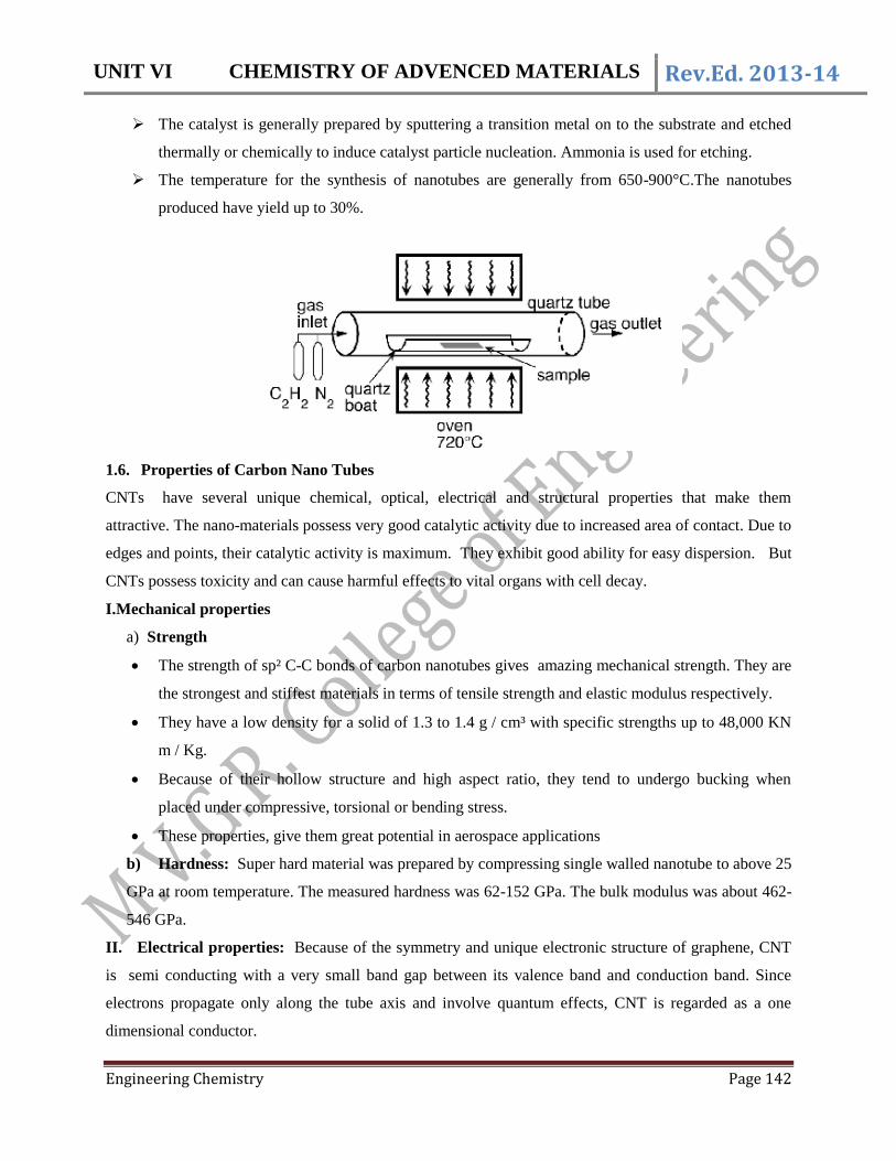
C) Chemical vapour deposition (CVD) method:
Chemical vapour deposition is achieved by putting a carbon source in the gas phase in an energy
source such as plasma or resistively heated coil, to transfer energy to gaseous carbon molecule.
The energy source ‘crack’ the molecules into reactive atomic carbon, which get settled on the
surface of the catalyst (viz, Ni, Fe or Co)
Excellent alignment, as well as positional control on nanometer scale, can be achieved by using
CVD. It is the most promisable method for industrial production of CNT, because of low cost
and direct growth of desired material on the catalyst surface.
UNIT VI CHEMISTRY OF ADVENCED MATERIALS Rev.Ed. 2013-14
Engineering Chemistry Page 142
The catalyst is generally prepared by sputtering a transition metal on to the substrate and etched
thermally or chemically to induce catalyst particle nucleation. Ammonia is used for etching.
The temperature for the synthesis of nanotubes are generally from 650-900°C.The nanotubes
produced have yield up to 30%.
1.6. Properties of Carbon Nano Tubes
CNTs have several unique chemical, optical, electrical and structural properties that make them
attractive. The nano-materials possess very good catalytic activity due to increased area of contact. Due to
edges and points, their catalytic activity is maximum. They exhibit good ability for easy dispersion. But
CNTs possess toxicity and can cause harmful effects to vital organs with cell decay.
I.Mechanical properties
a) Strength
The strength of sp² C-C bonds of carbon nanotubes gives amazing mechanical strength. They are
the strongest and stiffest materials in terms of tensile strength and elastic modulus respectively.
They have a low density for a solid of 1.3 to 1.4 g / cm³ with specific strengths up to 48,000 KN
m / Kg.
Because of their hollow structure and high aspect ratio, they tend to undergo bucking when
placed under compressive, torsional or bending stress.
These properties, give them great potential in aerospace applications
b) Hardness: Super hard material was prepared by compressing single walled nanotube to above 25
GPa at room temperature. The measured hardness was 62-152 GPa. The bulk modulus was about 462-
546 GPa.
II. Electrical properties: Because of the symmetry and unique electronic structure of graphene, CNT
is semi conducting with a very small band gap between its valence band and conduction band. Since
electrons propagate only along the tube axis and involve quantum effects, CNT is regarded as a one
dimensional conductor.

UNIT VI CHEMISTRY OF ADVENCED MATERIALS Rev.Ed. 2013-14
Engineering Chemistry Page 143
III. Vibrational properties: Atoms in CNT are continuously vibrating back and forth. They have
two modes of vibration which are Raman active.
IV. Optical properties: The optical properties of CNT are due to the absorption of
photoluminescence and Raman effect, which allows the quick and reliable characterization of nano tube
quality in terms of non tubular carbon content. CNT possess microwave absorption characteristics which
are useful in military radar systems.
V. Thermal properties: CNT are very good thermal conductors and exhibit a property called
ballistic condition.
VI. Functionalization: Grafting of chemical function at the surface of the nanotubes is called
functionalization. Functionalization gives scope for the addition of new properties to carbon nanotubes.
1.7. Engineering applications of Carbon Nanotubes (CNT)
The small dimensions, strength and the remarkable physical properties of these structures make CNTs a
very unique material with a whole range of promising applications. They are used in energy storage,
energy conversion devices, sensors, field emission displays and radiation sources, hydrogen storage
media and nanometer- sized semi conductor devices. They are used as nanometers in metrology,
biological and chemical investigations. They have emerged as a new alternative and efficient tool for
transporting and translocation therapeutic molecules. CNT can be functionalized with bioactive peptides,
proteins, nucleic acids and drugs and can be used to deliver their cargos to cells and organs.
Functionalized CNT display low toxicity and are not immunogenic and hence used in the field of nano
biotechnology and nano medicine.
Applications in industry and research:
CNTs are used to make space elevators, stab proof and bullet proof clothing due to their
superior mechanical properties.
CNT – polymer composites are used for making electrical cables and wires due to their
superior conductivity.
CNT infused with cellulose is used to make paper thin batteries. Here CNT acts as electrodes
allowing storage devices to conduct electricity, which can provide steady output comparable
to a conventional battery.
CNTs are used in solar panels due to their strong UV/Vis-Near IR absorption characteristics .
CNTs are used for coating textile fibres which is anti-bacterial, electrically conductive, flame
retardant with electro-magnetic absorption properties used in special equipment.
A spray-on mixture of CNT and ceramic coating gives unprecedented ability to resist damage
while absorbing LASER .
UNIT VI CHEMISTRY OF ADVENCED MATERIALS Rev.Ed. 2013-14
Engineering Chemistry Page 144
Hydrogen can be stored in the carbon nanotube, which can be used in the fuel cells. The
SWNTs are effective as hydrogen storage material for fuel cell driven electric vehicles. A
group of scientists has created a new, improved fuel-cell electrode that is very light in its
weight and thin. Composed of a network of single-walled carbon nanotubes, the electrode
functions nearly as conventional electrodes and renders the entire fuel cell much lighter
weight with greater efficiency.
Carbon nanotubes can replace platinum as a catalyst in fuel cells, which could significantly
reduce the overall cost. Carbon nanotube has advantage over platinum, since they are resistant
to corrosion.
The nanotube network from the fuel cell’s gas diffusion electrode is a layer of a porous
material that allows gas and water vapour to pass through to the catalyst layer. In the catalyst
layer, which typically consists of platinum particles, the protons and electrons of the gaseous
reactant material i.e., the fuel of the cell are separated and the electrons cause flow of
electricity.
The electric power densities produced using the Pt / CNT electrodes are larger than that of the
Pt/CB (carbon black) by a factor of two to four on the basis of the Pt load per power. CNTs are
thus found to be a good support of Pt particles for PEFC electrodes.
A catalyst having CNTs makes a reaction milder, safer and more selective.
CNTs are increasingly recognised as materials for catalysis, either as catalyst themselves or as
catalyst additives or as catalyst supportive materials.
The tightly packed, vertically aligned carbon nanotubes doped with nitrogen, are used as
cathodes in highly alkaline solution, to catalyze the reduction of oxygen more efficiently than
platinum.
Researchers have developed a novel catalyst using CNTs for the electrochemical reduction of
oxygen.
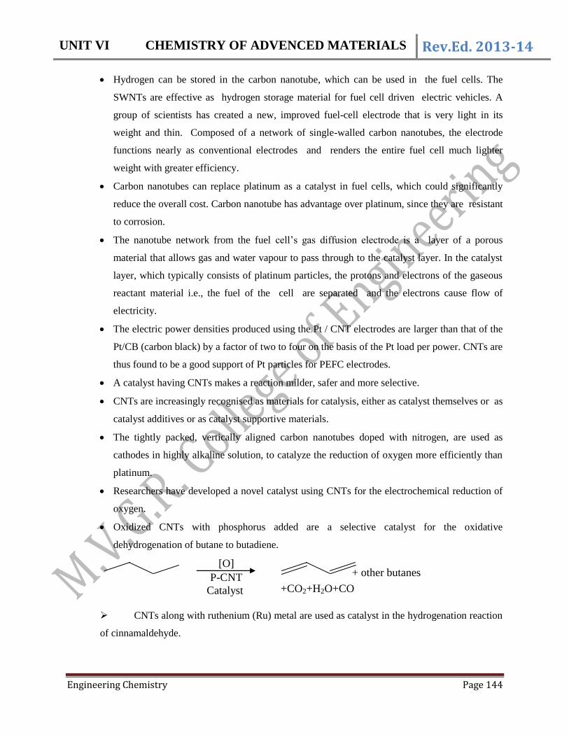
Oxidized CNTs with phosphorus added are a selective catalyst for the oxidative
dehydrogenation of butane to butadiene.
CNTs along with ruthenium (Ru) metal are used as catalyst in the hydrogenation reaction
of cinnamaldehyde.
[O]
P-CNT +CO2+H2O+CO
+ other butanes
Catalyst

UNIT VI CHEMISTRY OF ADVENCED MATERIALS Rev.Ed. 2013-14
Engineering Chemistry Page 145
Some chemical reaction that are carried out inside the nanotubes:
i) Reduction of nickel oxide (NiO) to Ni.
NiO Ni
ii) Reduction of AlCl3 to its base metal.
AlCl3 Al
iii) Cadmiun sulphide (CdS) crystals have been formed inside the carbon nanotubes by
reacting cadmium oxide (CdO) crystals with hydrogen sulphide gas (H2S) at 400°C.
CdO + H2S CdS + H2O
Applications in medicine:
Carbons nanotubes (CNTs) are being highly used in the fields of efficient drug delivery and bio-
sensing methods for disease treatment and health monitoring.
Functionalization of SWNTs enhance solubility of drugs and allow for efficient tumor
targeting/drug delivery systems. It prevents SWNTs from being cytotoxic and altering the
function of immune cells.
Researches show that functionalized carbon nanotubes are non- cytotoxic and preserve the
functionality of primary immune cells. Certain types of CNTs functionalized with lipids are
highly water soluble, which would make their movement through the human body easier and
would also reduce the risk of blockage of vital body organ pathways, thus making them more
useful as drug delivery vehicles.
CNTs as drug delivery vehicles have shown potential in targeting specific cancer cells with a
dosage lower than conventional dosage of drugs used and do not harm healthy cells and
significantly reduce the side effects.
Due to high electrochemically accessible surface area, high electrical conductivity and useful
structural properties, single walled nanotubes (SWNT) and multi-walled nanotubes (MWNT)in
highly sensitive non-invasive glucose detectors.
Carbon nanotubes can be used as multifunctional biological transporters and near- infrared agents
for selective cancer cell destruction.
An aligned carbon nanotube ultra sensitive biosensor for DNA detection was developed. The
design and fabrication of the biosensor was based on aligned single wall carbon nanotubes
(SWCNT) with integrated single- strand DNAs (ssDNA).
1.8. Fullerenes
The third newly discovered allotrope of carbon is Buck minister’s fullerene during laser spectroscopy
experiments. The structure of C60 resembles the geodesic dome (foot ball type) and named after its

UNIT VI CHEMISTRY OF ADVENCED MATERIALS Rev.Ed. 2013-14
Engineering Chemistry Page 146
architect Buck minister Fuller. In 1996, Prof. Robert. F. Curl Jr, Richard .E. Smalley and Sir Harold .W.
Kroto were awarded Nobel Prize for their discovery.
A fullerene is any molecule entirely composed of carbon, in the form of hollow sphere, ellipsoid ,
tube or plane. Thus fullerenes are of the following types:
1. Spherical fullerenes: They look like soccer (foot ball) ball and are often called bucky balls.
Fullerenes are similar in structure to graphite composed of stacked graphene sheets, linked
mostly of hexagonal or sometimes pentagonal / heptagonal rings. Buck minister’s fullerene C60 is
the simplest of all.
2. Cylindrical fullerenes: These are called carbon nanotubes or bucky tubes
3. Planar fullerenes: Graphene is an example of planar fullerene sheet.
1.9. Preparation of fullerenes
Fullerenes are prepared by vaporizing a graphite rod in He atmosphere when mixture of fullerenes
formed are separated by multi step solvent extraction methods. C60 is isolated by column chromatography
using alumina/hexane solvent system.
1.10. Properties of fullerenes
The bucky ball has cage like structure with certain unique properties. It is stable, denoted as C60 and has
sp2 hybridized carbon atoms, whose reactivity is increased by attaching active groups on the surface. It
exists as a discrete molecule. C60 is a mustard coloured solid . When its thickness increases, it appears
brown and then black. It is moderately soluble in the common organic solvents, especially aromatic
hydrocarbons like toluene. It dissolves in benzene forming a deep magenta solution. It has a high tensile
strength of any known 2D structure or element and has a high packing density. It can be compressed to
30% of its original volume, without destroying its cage structure. It is stable up to 600 °C and undergoes
sublimation under vacuum at 600°C. it undergoes electrophillic addition at 6-6 double bonds. Other atoms

UNIT VI CHEMISTRY OF ADVENCED MATERIALS Rev.Ed. 2013-14
Engineering Chemistry Page 147
can be tapped inside to form inclusion compounds. When metal atoms are tapped inside, it is called
metallo fullerene, the best example being steel.
1.11. Engineering applications
Fullerenes have amazing conducting, magnetic, optical and mechanical properties.
1. They can easily accept electrons, therefore, they may be used as charge carries in batteries.
2. They can be used as organic photo voltaic cells as they have optical absorption properties.
3. Alkali metal fullerides are super conductors.
4. They can be used as soft ferro-magnets.
5. Its spherical structure makes it suitable to be used as a lubricant.
6. Because of their extreme resilience and sturdy nature, fullerenes are used in manufacture of
armor.
7. The water soluble derivatives inhibit the HIV-1 protease enzyme. Hence they are useful in the
treatment of HIV.
8. These are used as powerful anti-oxidants.
9. The fullerenes and fullerene black are chemically reactive and are added in the manufacture of
copolymers with specific physical and mechanical properties.
10. They are used as catalysts as they have the ability to accept and transfer hydrogen atoms. They
are highly effective in converting methane to higher hydrocarbons.
-oOo-

UNIT VI CHEMISTRY OF ADVENCED MATERIALS Rev.Ed. 2013-14
Engineering Chemistry Page 148
2. LIQUID CRYSTALS
Liquid crystals (LCs) are a state of matter that has properties between those of a conventional liquid and
a solid crystal. In 1888, Austrian botany physiologist Friedrich Reinitzer, examined that cholesteryl
benzoate had two distinct melting points. At 145.5 °C it melts into a cloudy liquid and at 178.5 °C it
melts again and the cloudy liquid becomes clear, which now belongs to cholesteric liquid crystals. Liquid
crystals may flow like a liquid, but their molecules may be oriented in crystal like organized way.
Liquid crystals have generally a rod like molecular structure, rigidness of the long axis and easily
polarizable substituents. The distinguishing characteristic of the liquid crystalline state is the tendency of
the molecules (mesogens) to point along a common axis, called the director. The tendency of the liquid
phase molecules are in contrast to this, which have no intrinsic order and hence show isotropic
behaviour. In the solid state the molecules are highly ordered and have little translational freedom and
thus are anisotropic. The tendency of the liquid crystal molecules to point along the director leads to a
condition known as anisotropy comparable to solid crystals.
2.1.Types of Liquid Crystals
This classification is based on breaking order of the solid state and has two types:
1. Thermotropic liquid crystals 2. Lyotropic liquid crystals
2.1.1 Thermotropic liquid crystals
Thermotropic phases are those that occur in a certain temperature range. If temperature is too high,
thermal motion may destroy the ordering in the LC phase and isotropic liquid phase will occur. Ex:
Cholesteryl benzoate, p-azoxy anisole etc. These have been classified into following types.
a) Smectic liquid crystals
b) Nematic liquid crystals
c) Cholesteric liquid crystals
a) Smectic (or) soap-like liquid crystals: Smectic is the name given by G. Friedel for certain
mesophase with mechanical properties similar to soaps.
.
Smectic phases

UNIT VI CHEMISTRY OF ADVENCED MATERIALS Rev.Ed. 2013-14
Engineering Chemistry Page 149
All smectic LCs have layered structure, with definite interlayer spacing. This can be measured by X-ray
diffraction. Smectic liquid crystals on heating retain long-range order, yielding smectic phase. They lose
the periodicity with in the planes, but retain the orientation and arrangement in equi-spaced planes.
b) Nematic or thread like liquid crystals: These are less ordered. These on heating lose their planar
structure, but retain a parallel alignment. Thus they retain orientation, but lose periodicity. The
molecules tie parallel to each other but can move up or down or sideways or can rotate along their axes.
N-paramethoxy benzylidene – p – butyl aniline changes to nematic liquid at 240C and this state persists
up to 430C, after which it melts in to an isotropic liquid. Nematic liquid crystals do not conduct
electricity when they are in pure form. They flow like liquids, but their mechanical (like viscosity,
elasticity) electrical (like dielectric constant) , optical properties and diamagnetism etc., depend upon the
direction along which they are measured.
Nematic phase
c) Cholesteric liquid crystals: These are optically active and possess the arrangement of molecules
similar to those in nematic type. Such liquid crystals are characterized by very high optical rotation,
probably a thousand times greater than that of their crystalline variety. Moreover, on raising the
temperature, the pitch decreases. This results in corresponding change in the wavelength of reflection.
They are named so because the skeleton of these substances pass through a state similar to that of
cholesterol, a steroid present in blood.
UNIT VI CHEMISTRY OF ADVENCED MATERIALS Rev.Ed. 2013-14
Engineering Chemistry Page 150
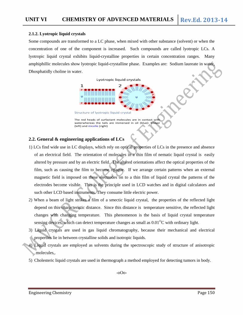
2.1.2. Lyotropic liquid crystals
Some compounds are transformed to a LC phase, when mixed with other substance (solvent) or when the
concentration of one of the component is increased. Such compounds are called lyotropic LCs. A
lyotropic liquid crystal exhibits liquid-crystalline properties in certain concentration ranges. Many
amphiphillic molecules show lyotropic liquid-crystalline phase. Examples are: Sodium laureate in water,
Dhosphatidly choline in water.
2.2. General & engineering applications of LCs
1) LCs find wide use in LC displays, which rely on optical properties of LCs in the presence and absence
of an electrical field. The orientation of molecules in a thin film of nematic liquid crystal is easily
altered by pressure and by an electric field. The altered orientations affect the optical properties of the
film, such as causing the film to become opaque. If we arrange certain patterns when an external
magnetic field is imposed on these electrodes on to a thin film of liquid crystal the patterns of the
electrodes become visible. This is the principle used in LCD watches and in digital calculators and
such other LCD based instruments. They consume little electric power.
2) When a beam of light strikes a film of a smectic liquid crystal, the properties of the reflected light
depend on this characteristic distance. Since this distance is temperature sensitive, the reflected light
changes with changing temperature. This phenomenon is the basis of liquid crystal temperature
sensing devices, which can detect temperature changes as small as 0.01OC with ordinary light.
3) Liquid crystals are used in gas liquid chromatography, because their mechanical and electrical
properties lie in between crystalline solids and isotropic liquids.
4) Liquid crystals are employed as solvents during the spectroscopic study of structure of anisotropic
molecules,.
5) Cholesteric liquid crystals are used in thermograph a method employed for detecting tumors in body.
-oOo-

UNIT VI CHEMISTRY OF ADVENCED MATERIALS Rev.Ed. 2013-14
Engineering Chemistry Page 151
3. FIBRE RIENFORCED PLASTICS
Fibre – Reinforced plastic (FRP) is one of a composite material. An FRP composite is defined as
a polymer that is reinforced with a fibre. A composite is an artificially prepared multiphase material. . The
primary function of fibre – reinforcement is to carry load along the length of the fibre and to provide the
strength and stiffness. Composite materials consists of two phases, one is called the matrix which is
continuous and surrounds the other phase called the dispersed phase (reinforcement). FRP is produced by
reinforcing a plastic matrix with a high strength fibre material such as glass, graphite, alumina, carbon,
boron, beryllium and aromatic polyamides. Glass fibre is most widely used reinforced fibre, because of its
durability, acid/water/fire proof nature of glass. The polymer is usually an epoxy, vinyl ester or polyester
thermosetting plastic. The composite materials are prepared by binding two or more homogeneous
materials with different material properties to derive a final product with certain desired material and
mechanical properties.
3.1. Composite Components
i) Fibres: The composite’s properties are mainly influenced by the choice of fibers. These have
generally higher stress capacity and linearly elastic until failure. In civil engineering materials ,
three types of fibres viz. carbon, glass and aramid fibres are used. They have different properties.
ii) Matrix: Matrix should transfer the forces between the fibers and protect the fibers from the
environment. Commonly used matrices are thermo-sets viz. vinyl ester or epoxy. Epoxys are
employed mostly as they have good strength, bond, creep properties, chemical resistances and low
cost.
3.2. Methods for producing FRP
The Fibre – reinforced plastic are produced by suitably bonding a fiber material with a resin matrix and
curing the same under pressure and heat. The common resin matrices used in FRP are polyesters, epoxy,
phenolics, silicones, melamine, vinyl derivatives and polyamides. The following common methods are
employed as processing techniques for producing FRP.
a) Matched metal die moulding: This is the most efficient and economical method for mass production
of high strength parts. The parts are press moulded in matched male and female moulds at a pressure
of 200 -300 psi and at a temperature of 235 – 260 oC. The upper mould containing the resin and
reinforced fibres is pressed on to the lower mould.
b) Injection moulding : A mix of short fibres and resin is forced by a screw or plunger through an
orifice into the heated cavity of a closed matched metal mould and allowed to curve. This is suitable
for reinforced thermoplastics.

UNIT VI CHEMISTRY OF ADVENCED MATERIALS Rev.Ed. 2013-14
Engineering Chemistry Page 152
c) Hand – lay- up: In this method, the reinforcing mat or fabric is cut to fit, laid in the female mould
and saturated with resin by hand, using a brush, roller or a spray gun. Layers are built up to their
desired thickness and then the laminate is cured to render it hard, generally at room temperature. This
is the simplest method for thermosetting composites.
d) Spray – up: This method is well suited for complex thermosetting moulds and its portable equipment
is amenable for onsite fabrication and repair. Short lengths of reinforcement and resin are projected by
a specially designed spray gun so that they are deposited simultaneously on the surface of the mould.
Curing is done with a catalyst in the resin at room temperature.
e) Continuous lamination: This is the most economical method of producing flat and corrugated panels,
glazings etc. In this method, reinforcing mats or fabrics are impregnated with resin, run through and
resin content. They are then cured in a heating chamber.
f) Centrifugal casting: In this method, chopped fibres and resins are placed inside a mandrel and are
uniformly distributed as the mandrel is rotated inside an oven. This method is suitable for providing
round, oval, tapered or rectangular parts.
g) Pultrusion: In this method, continuous fibre strands combined with mat or woven fibres for cross-
strength, are impregnated with resin and pulled through long heated steel die. The die shapes the
product and controls the resin content. This method is suitable for providing shapes with high uni-
directional strength.
h) Filament windings: In this method, continuous fibre strands are wound on a suitably shaped mandrel
or core and positioned in a predetermined pattern. The strands may be pre-impregnated or the resin
may be applied during or after winding. Final curing is done by heating.
3.3. Types of Fiber Reinforced Plastics
(a) Glass Fiber Reinforced Plastics (GFRP): Glass fibres are basically made by mixing silica sand,
limestone, folic acid and other minor ingredients. The mix is heated up to 1260 oC and allowed
through fine holes in a platinum plate. The glass strands are cooled, gathered and wound. For example,
aluminium lime borosilicate glass fibres have high electrical insulating properties, low susceptibility to
moisture and high mechanical properties. Glass fibres have excellent characteristics equal or better to
steel in certain forms.
Properties
They have high ratio of surface area to weight. As a result, they are more useful and also
they are vulnerable for chemical attacks.
Blocks of fibres trap the air, which makes them good thermal insulators. Their thermal
resistance is 0.04W/mk.

UNIT VI CHEMISTRY OF ADVENCED MATERIALS Rev.Ed. 2013-14
Engineering Chemistry Page 153
The fresh and thin fibres are the strongest. If the surface of the FRP is more, its strength
is less. Moisture is easily adsorbed and worsen the microscopic cracks, surface defects
etc.
It can undergo more elongation before it breaks.
The viscosity of molten glass is very important. If the viscosity is more, the FRP breaks
during drawing or if the viscosity is too low, the glass will form droplets.
Uses: Fibre glass possess low density, high tensile strength, high impact resistance and excellent
chemical and corrosion resistance and are stiff and rigid. They are used in making automotive parts,
storage tanks, plastic pipes, industrial floorings, transport vehicles to boost fuel efficiency.
(b) Carbon Fiber Reinforced Plastics (CFRP) : Carbon fibres have high modulus of elasticity and
low elongation coefficient. These are highly stiff, do not absorb water and are resistant to chemical
attack. They do not undergo stress corrosion, do not show any creep and withstand fatigue. They are
electrically conductive and might be corrected in a galvanic way, when they are in contact with steel.
Properties
They are alkali resistant and are resistant to corrosion. Hence, they are used for corrosion
control and rehabilitation of concrete structure.
They have low thermal conductivity.
These have high strength to weight ratio, which eliminates the requirement of heavy
construction equipment and supporting structures.
These are available in rolls of very long length. Therefore, they need very few joints
avoiding laps and their transportation is easy.
CFRP has a short curing time. So, they reduce the project duration and downtime of the
structure to a great extent.
CFRP is a bad conductor of electricity and is non-magnetic.
(c) Aramid Fiber Reinforced Polymers (Bullet Proof Plastic): Aramids (Aromatic polyamides)
belong to family of nylons (for example, Nomex, Kevlar) which are being used to make bullet proof
vests and puncture resistant tyres. They are also used in the manufacture of helmets. They are
sensitive to elevated temperatures, moisture and ultraviolet radiation. But they have problems with
relaxation and stress corrosion.
i) Kevlar: It is a poly p-phenylene tere-phthalamide .It has recurring units joined by
amide links, which have a carbonyl group and an amine group. The repeating units
consist of benzene rings as shown:

UNIT VI CHEMISTRY OF ADVENCED MATERIALS Rev.Ed. 2013-14
Engineering Chemistry Page 154
NH2
H2N
Cl
Cl
O
O
+-2n HCl O
N
H
N
H
H
OH
O
n
n
ii) Nomex: This is produced by a condensation reaction between m-phenylenediamine and iso-
phthaloyl chloride. It has meta-phenylene groups which are attached to phenyl ring at 1 and
3 positions as shown below:
NH
C
O
C
O
HN
nNomex
Properties
They appear yellow in colour, have low density and high strength. These have good impact
resistance, abrasion and chemical resistance and resistance to thermal degradation. However
some grades of aramids undergo degradation when exposed to UV-light.
Applications
They are used in manufacture of protective apparels such as gloves, bullet proof vests, motorcycle
protective clothing etc. Belts and hosing for industrial and automotive parts, aircraft body parts,
fiber optic and electro mechanical cables are also made with them.
3.4 General advantages of FRP
They can provide maximum stiffness to density ratio 3.5 to 5 times that of aluminium or steel.
They can absorb impact stress and have high fatigue endurance limits.
They strengthen the material properties and reduce corrosion potential.
General properties of FRP
Their strength is more than 5 times that of steel.
They are resistant to chemical attack and do not undergo rusting.
They withstand the temperatures in the range from -196 _ 400
oC and are used in making
bullet proof vests
UNIT VI CHEMISTRY OF ADVENCED MATERIALS Rev.Ed. 2013-14
Engineering Chemistry Page 155
3.5 Conducting Polymers: Most polymeric materials are poor conductors of electricity because of the
non-availability of large number of free electrons for the conduction process. Thus most of the polymers
are used as insulators. However some polymers have electrical conductivity and can be used in place of
metals due to their light weight and low cost,
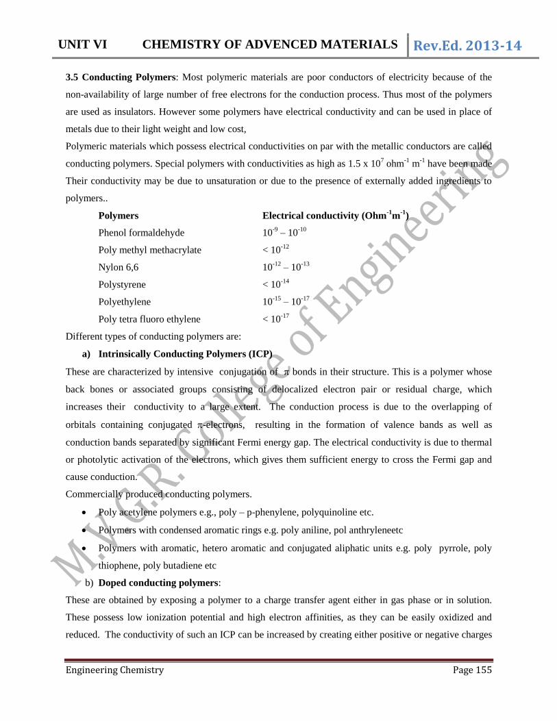
Polymeric materials which possess electrical conductivities on par with the metallic conductors are called
conducting polymers. Special polymers with conductivities as high as 1.5 x 10⁷ ohm
-1 m
-1 have been made
Their conductivity may be due to unsaturation or due to the presence of externally added ingredients to
polymers..
Polymers Electrical conductivity (Ohm-1
m-1
)
Phenol formaldehyde 10-9
– 10-10
Poly methyl methacrylate < 10-12
Nylon 6,6 10-12
– 10-13
Polystyrene < 10-14
Polyethylene 10-15
– 10-17
Poly tetra fluoro ethylene < 10-17
Different types of conducting polymers are:
a) Intrinsically Conducting Polymers (ICP)
These are characterized by intensive conjugation of bonds in their structure. This is a polymer whose
back bones or associated groups consisting of delocalized electron pair or residual charge, which
increases their conductivity to a large extent. The conduction process is due to the overlapping of
orbitals containing conjugated -electrons, resulting in the formation of valence bands as well as
conduction bands separated by significant Fermi energy gap. The electrical conductivity is due to thermal
or photolytic activation of the electrons, which gives them sufficient energy to cross the Fermi gap and
cause conduction.
Commercially produced conducting polymers.
Poly acetylene polymers e.g., poly – p-phenylene, polyquinoline etc.
Polymers with condensed aromatic rings e.g. poly aniline, pol anthryleneetc
Polymers with aromatic, hetero aromatic and conjugated aliphatic units e.g. poly pyrrole, poly
thiophene, poly butadiene etc
b) Doped conducting polymers:
These are obtained by exposing a polymer to a charge transfer agent either in gas phase or in solution.
These possess low ionization potential and high electron affinities, as they can be easily oxidized and
reduced. The conductivity of such an ICP can be increased by creating either positive or negative charges
UNIT VI CHEMISTRY OF ADVENCED MATERIALS Rev.Ed. 2013-14
Engineering Chemistry Page 156
on the polymer backbone by oxidation or reduction. This technique is called doping, which is of two
types.
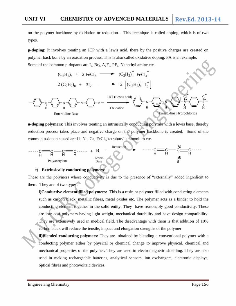
p-doping: It involves treating an ICP with a lewis acid, there by the positive charges are created on
polymer back bone by an oxidation process. This is also called oxidative doping. PA is an example.
Some of the common p-dopants are I2, Br2, A2F5, PF6, Naphthyl amine etc.
(C2H2)n + (C2H2)n FeCl4
2 (C2H2)n + 2 (C2H2)n I3
2 FeCl3
3I2
N
H
N
H
N N N
H
N
H
N N
H H
Cl ClHCl (Lewis acid)
Oxidation
Emeroldine Base Emeroldine Hydrochloride
n-doping polymers: This involves treating an intrinsically conducting polymer with a lewis base, thereby
reduction process takes place and negative charge on the polymer backbone is created. Some of the
common n-dopants used are Li, Na, Ca, FeCl3, tetrabutyl ammonium etc.
CH
CH
CH
CH
+ BReduction
CH
CH
C CH
BPolyacetyleneLewis Base
c) Extrinsically conducting polymers:
These are the polymers whose conductivity is due to the presence of “externally” added ingredient to
them. They are of two types.
i)Conductive element filled polymers: This is a resin or polymer filled with conducting elements
such as carbon black, metallic fibres, metal oxides etc. The polymer acts as a binder to hold the
conducting element together in the solid entity. They have reasonably good conductivity. These
are low cost polymers having light weight, mechanical durability and have design compatibility.
They are extensively used in medical field. The disadvantage with them is that addition of 10%
carbon black will reduce the tensile, impact and elongation strengths of the polymer.
ii)Blended conducting polymers: They are obtained by blending a conventional polymer with a
conducting polymer either by physical or chemical change to improve physical, chemical and
mechanical properties of the polymer. They are used in electromagnetic shielding. They are also
used in making rechargeable batteries, analytical sensors, ion exchangers, electronic displays,
optical fibres and photovoltaic devices.

UNIT VI CHEMISTRY OF ADVENCED MATERIALS Rev.Ed. 2013-14
Engineering Chemistry Page 157
d) Coordination conducting polymers (Inorganic polymers):
This is a charge transfer complex containing polymer obtained by combining a metal atom with a
polydentate ligand. The degree of polymerization in such polymers is small (18).
Applications of conducting polymers: The conjugation length of a polymer chain, doping level,
temperature of operation, frequency of current are some important factors which influence the
conductivity of a conducting polymer. They have wide applications due to their low weight, easy process
of manufacture and have good mechanical properties. They possess good conductivity and store charge.
They are transparent to X rays. They can be easily processed with product stability and efficient
recycling. Some of their important applications are:
1. In rechargeable light weight batteries based on perchlorate doped poly acetylene –
lithium system, which is 10 times lighter than lead storage batteries.
2. In optical display devices based on poly thiophene.
3. In wiring systems in aircrafts and aerospace components.
4. In telecommunication systems.
5. In antistatic coatings for clothing.
6. In electromagnetic screening materials.
7. In electronic devices such as transistors and diodes.
8. In solar cells and drug delivery system for human body.
9. In molecular wires and molecular switches.
However their conductivities are inferior to metal and hence have limited applications compared to
metals.
3.6. Biodegradable polymers
The polymers which undergo degradation when exposed to moisture heat, oxygen, ozone and
microorganisms etc. are called Biodegradable polymers. These external agents lead to the breakdown of
chemical structure and this in turn changes the properties of polymers.
Biodegradable polymers are defined as degradable polymer in which degradation results from the
action of naturally occurring microorganisms such as bacteria, fungi and algae.
Biodegradable plastics are two types. They are hydro biodegradable plastics (HBP), which
undergo chemical degradation by hydrolysis and Oxo-biodegradable plastics (OBP), which undergo
chemical degradation by oxidation.
HBP, OBP on degradation forms the same products; generally both are converted into carbon
dioxide (CO2), water (H2O) and biomass.

UNIT VI CHEMISTRY OF ADVENCED MATERIALS Rev.Ed. 2013-14
Engineering Chemistry Page 158
HBP tend to degrade more quickly than OBP. HBP emits methane in anaerobic degradation
conditions, but OBP does not emit methane.
HBP are naturally occurring biodegradable polymers mostly from agricultural resources such as
corn, wheat, sugar cane etc. naturally occurring biodegradable. HBP are classified into four groups.
1. Polysaccharides E.g.: Starch & Cellulose 2. Proteins E.g.: Gelatin, Silk, Wool.
3. Polyesters 4. Others E.g.: lignin, Shellac, Natural Rubber.
OBP can be made from by products of oil or natural gases. There are many polymers produced
from petrochemicals or biological sources are synthesized biodegradable polymers.
Polyalkylene esters, polylactic acid and its co-polymers, Poly amide esters polyvinyl esters,
polyvinyl alcohol, polyanhydrides are biodegradable synthetic resins.
Properties:
Biodegradable polymers are non-toxic.
They are able to maintain good mechanical integrity until degraded.
They are capable of controlling rates of degradation.
Applications:
They are used in sutures, suture is a medical device used to hold body tissues together after an
injury or surgery and tissue engineering.
Used in drug delivery systems.
Used to coat a stent and release drugs in a controlled way.
Used in dental devices and orthopedic fixation devices.
-oOo-

UNIT VI CHEMISTRY OF ADVENCED MATERIALS Rev.Ed. 2013-14
Engineering Chemistry Page 159
4. SOLAR CELLS
Solar energy is through the sun’s rays that reach the earth. Solar energy originates from the
thermonuclear fusion reactions taking place in the sun. Only 0.2 to 0.5% of the solar energy reaching the
earth is trapped in photosynthesis. Thus only a tiny fraction of the solar energy reaching the earth drives
all our ecosystems. Solar energy is a renewable eco-friendly, perennial source of energy.
In 1830’s the British astronomer John Herschel used a solar thermal collector box to cook food
during an expedition to Africa.
Solar energy can be converted into Electricity by the following two ways.
1. Photo voltaic cells or Solar cells 2. Solar power plants
4.1. Photovoltaic cells: (PV cell (or) Solar cell (or) Solar Battery)
The basic unit of a photovoltaic system is the solar cell. The most common solar cells are made up of
highly refined silicon. These solar cells can change the sunlight directly into electricity.
Working principle of a solar cell: (Photo voltaic cell):
Solar cell constitutes a p-type semiconductor in
contact with a n-type semiconductor. Due to close
contact, the migration of holes or electrons is limited.
The outer layer of p-type semiconductor is struck by a
beam of light from the sun. When enough sunlight is
absorbed by the semiconductor, electrons are
dislodged from the atoms, and migrate to the surface
leaving positive holes. So a potential difference arises
between the p-type and n-type semiconductors. When
the terminals are connected to an external circuit,
electrons flows from n-layer to p-layer, which converts
directly the solar energy into electrical energy. This
device is called as a photo voltaic cell. The
photovoltaic individual cells can vary in size from
about 0.5 inches to about 4 inches. However one
single cell produces 1 or 2 watts. To increase the
power put cells are electrically connected out into a
packaged module.
The modules can be further connected to form an array. It refers to an entire photovoltaic power plant.

UNIT VI CHEMISTRY OF ADVENCED MATERIALS Rev.Ed. 2013-14
Engineering Chemistry Page 160
Advantages of Photovoltaic power plants
1. The conversion of sunlight directly to electricity does not need any bulky mechanical generators.
2. PV arrays can be installed quickly in any size.
3. The environmental impact is minimal, requiring no water for system cooling and generating no
by products.
4. These will be producing DC (Direct current) which is used for small loads.
Disadvantages
1. The photovoltaic array is dependent on sunlight which is not constant but depends on location,
time of the day, time of year and weather conditions.
2. The Photovoltaic cells used for commercial applications must have an arrangement to convert the
resultant DC power into AC power.
5.3. Solar power plant
Solar thermal power plants generate electricity by using the heat from solar thermal collectors. The sun
rays are used to heat a fluid to a very high temperatures. The fluid is then circulated through pipes and
transfers its heat to water to produce steam. The steam drives the turbine to produce mechanical energy
and into electricity by using a conventional generator. The heat required is produced by the solar
collectors. Solar thermal technologies use concentrator systems to achieve the high temperatures needed
to heat the fluid.
There are three main types of solar thermal power systems.
1. Solar parabolic trough
2. Solar dish
3. Solar power tower.
1. Parabolic trough: A long parabolic shaped reflector that focuses the sun’s rays on to a receiver
pipe. The collector tilts with the sun as the sun moves from east to west during the day to ensure that

UNIT VI CHEMISTRY OF ADVENCED MATERIALS Rev.Ed. 2013-14
Engineering Chemistry Page 161
the sun is continuously focused on the receiver. Because of this parabolic shape of a trough it can
focus the sun light 30 to 100 times compare to the normal intensity. The receiver pipe located at the
focal line of the trough to achieve over 750 oF.
2. Solar Dish
The “Solar field” has many parallel rows of parabolic trough collectors aligned on a north-south
horizontal axis. The receiver fluid gets heated and runs to the series of “heat exchangers”. Here it can
transfer the heat to water to generate high pressure super heated steam. The hot fluid passes through the
heat exchangers cools down, and then re-circulated through the solar field to get heated up again.
Parabolic trough power plants can use fossil fuel combustion to supplement the solar out put during the
cloudy days.
A solar dish system uses concentrating solar collector that track the sun. So the concentrated solar energy
is collected at the focal point of the solar dish. The concentration ratio is much higher than the solar
trough typically over 2000 with temperature over 1380 oF. The engine in a solar dish system converts
heat to mechanical power by compressing the working fluid when it is cold, heating the compressed
working fluid, and then expanding the fluid through a turbine (or) with a piston to produce work, then it is
converted into electric power.
5.4. Solar power tower
A solar power tower or a central receiver generates electricity from sunlight by focusing concentrated
solar energy on a tower mounted heat exchanger. This uses the system of hundreds to thousands of flat-

UNIT VI CHEMISTRY OF ADVENCED MATERIALS Rev.Ed. 2013-14
Engineering Chemistry Page 162
tracking mirrors called heliostats to reflect and concentrate the Sun’s energy to a central receiver tower.
The energy can be concentrated as much as 1500 times.
The energy losses are minimized as solar energy is being directly transferred by reflection from the
heliostats to a single receiver, rather than being moved through a transfer medium. Power towers must be
large to be economical. This is a promising technology for large scale grid-connected power plants.
4.5. Solar collectors
1. Non concentrating collectors
The collector area is same as the absorber area. Flat plate collectors are the non-concentrating
collectors, and are used when temperatures are below 200 oF.
It consists:
a) Flat plate: It absorbs the solar energy.
b) Transparent cover: It allows the solar energy to pass through and to reduce the loss of heat.

UNIT VI CHEMISTRY OF ADVENCED MATERIALS Rev.Ed. 2013-14
Engineering Chemistry Page 163
c) Heat transport fluid: It is flowing through tubes to remove heat from the absorber.
2. Concentrating collectors
The area intercepting the solar radiation is more than the absorber area. Concentrating solar
systems require water for regular cleaning and for cooling the turbine generator.
Advantages
a) Very high temperatures are reached. High temperatures are suitable for electricity generation.
b) Good efficiency by concentrating sunlight hence current systems can get better efficiency.
c) A large amount of energy can be produced by using inexpensive mirrors.
d) Concentrated light can be redirected to a suitable location for illumination.
e) Heat can be stored by using molten salts in underground tank. This energy is used to be
converted into electricity during cloudy days and overnight conditions.
Disadvantages
a) These systems require sun tracking to collect the focused sun light.
b) In concentrating systems electricity drops drastically in cloudy condition.
-oOo-
UNIT VI CHEMISTRY OF ADVENCED MATERIALS Rev.Ed. 2013-14
Engineering Chemistry Page 164
5. Green House Effect
The green house effect is a naturally occurring process that aids in heating the surface of earth and its
atmosphere. It results from the fact that certain atmospheric gases, such as CO2, water vapour and
methane are able to change the energy balance of the planet by absorbing long wave radiation (IR rays) of
the solar radiation reaching the earth.
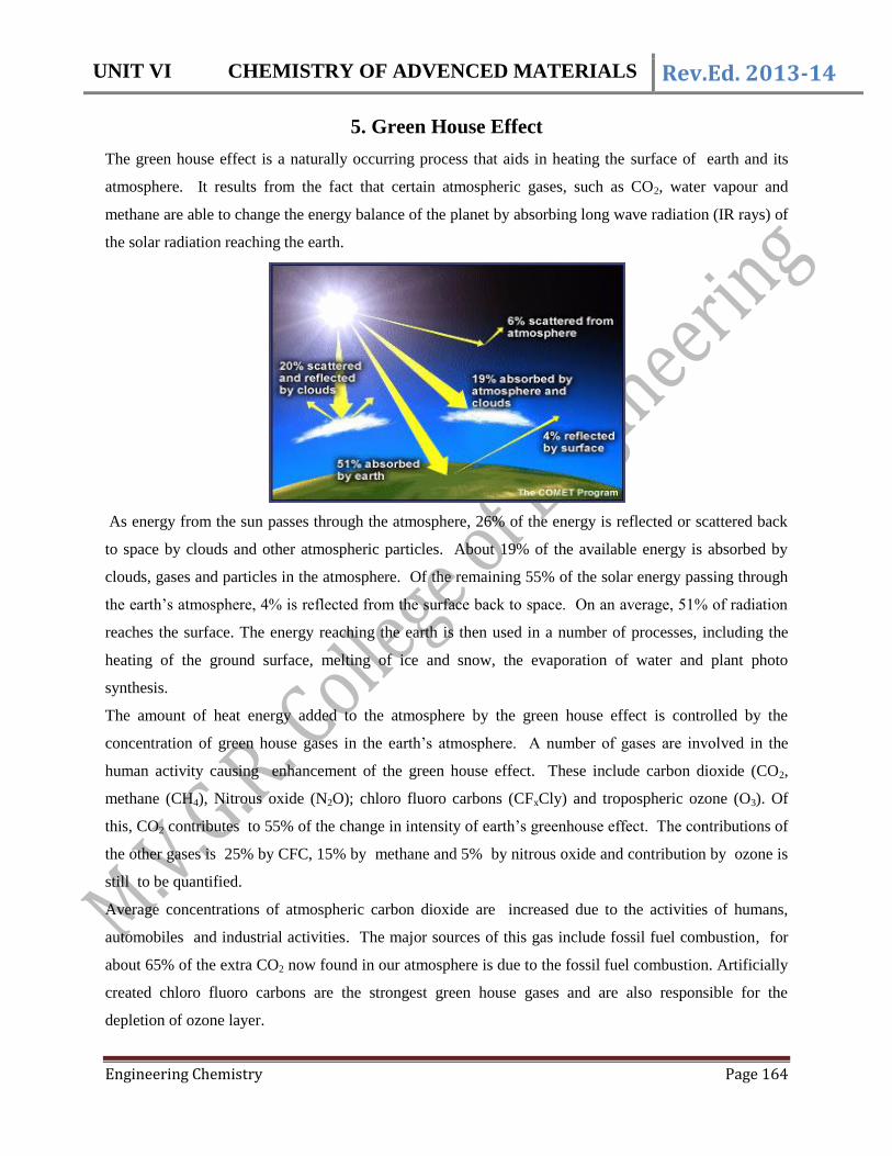
As energy from the sun passes through the atmosphere, 26% of the energy is reflected or scattered back
to space by clouds and other atmospheric particles. About 19% of the available energy is absorbed by
clouds, gases and particles in the atmosphere. Of the remaining 55% of the solar energy passing through
the earth’s atmosphere, 4% is reflected from the surface back to space. On an average, 51% of radiation
reaches the surface. The energy reaching the earth is then used in a number of processes, including the
heating of the ground surface, melting of ice and snow, the evaporation of water and plant photo
synthesis.
The amount of heat energy added to the atmosphere by the green house effect is controlled by the
concentration of green house gases in the earth’s atmosphere. A number of gases are involved in the
human activity causing enhancement of the green house effect. These include carbon dioxide (CO2,
methane (CH4), Nitrous oxide (N2O); chloro fluoro carbons (CFxCly) and tropospheric ozone (O3). Of
this, CO2 contributes to 55% of the change in intensity of earth’s greenhouse effect. The contributions of
the other gases is 25% by CFC, 15% by methane and 5% by nitrous oxide and contribution by ozone is
still to be quantified.
Average concentrations of atmospheric carbon dioxide are increased due to the activities of humans,
automobiles and industrial activities. The major sources of this gas include fossil fuel combustion, for
about 65% of the extra CO2 now found in our atmosphere is due to the fossil fuel combustion. Artificially
created chloro fluoro carbons are the strongest green house gases and are also responsible for the
depletion of ozone layer.
UNIT VI CHEMISTRY OF ADVENCED MATERIALS Rev.Ed. 2013-14
Engineering Chemistry Page 165
The green house effect causes the atmosphere to trap more heat energy at the earth’s surface and within
the atmosphere by absorbing and re-emitting long wave energy, among which 90% is intercepted and
absorbed by greenhouse gases. Without the greenhouse effect, the earth’s average global temperature
would be -180C, rather than present 15
0C. Because of this greenhouse gases, earth’s global temperature is
increasing by 0.3 to 0.6 oC, since the beginning of this century. By the middle of next century, earth’s
global temperature may be 1-30C higher than today.
6. GREEN CHEMISTRY
Introduction: Green chemistry is also called as sustainable chemistry. It is a philosophy of chemical
research and engineering which encourages the design of products and processes that minimize the use
and generation of hazardous substances potentially dangerous to life on earth. The concept of green
chemistry (Environmentally benign synthesis) was coined by Paul Anastas of America. He enunciated 12
principles of Green chemistry in 1994 towards ideal synthetic methods to save natural resources.
“Green chemistry is the use of chemistry for pollution prevention by environmentally – conscious design
of chemical products and processes that reduce or eliminate the use or generation of hazardous
substances”.
6.1. Need for Green Chemistry
The 20th century brought the highest scientific development with respect to various benefits to the
mankind, but in turn has been responsible for a number of environmental problems at local and global
level. Our environment is to be protected from increasing chemical pollution associated with
contemporary life styles and emerging technologies. This is essential for survival of life systems.
Green chemistry is an essential piece of comprehensive program to protect human health and
environment. Green chemistry includes chemical process or technology that improves the environment
and thus our quality of life. Green chemistry applies across life cycle of a chemical product including
design, manufacture and use.
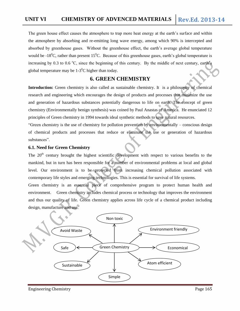
Green Chemistry
Non toxic
Simple
Economical Safe
Avoid Waste
Sustainable
Environment friendly
Atom efficient

UNIT VI CHEMISTRY OF ADVENCED MATERIALS Rev.Ed. 2013-14
Engineering Chemistry Page 166
6.2. The Principles of Green Chemistry
Green chemistry is considered as a science based, non-regulatory, economically driven approach and
essential piece of a comprehensive system to achieve the goals of environmental protection, human
health, sustainable development and eco-efficiency. Paul. T. Anastas and John Warner proposed twelve
principles of green chemistry. These are the guidelines for the development of next generation products,
processes and design of more efficient synthesis.
1. It is better to prevent waste than to treat or cleanup waste after it is formed.
2. Synthetic materials should be designed to maximize the incorporation of all materials used in the
process into the final product.
3. Wherever practicable, synthetic methodologies should be designed to use and generate substances
that possess little or no toxicity to human health and environment.
4. Chemical products should be designed to preserve efficacy of function while reducing their
toxicity.
5. The use of auxiliary substances ( such as solvent, separation agents etc) should be made
unnecessary wherever possible.
6. Energy requirements should be recognized for their environmental and economic impacts and
they should be minimized. Synthetic methods should be conducted at ambient temperature and
pressure.
7. A raw material or feed stock should be renewable rather than depleting, wherever technically and
economically practicable.
8. Unnecessary derivations (blocking groups, protection/ deprotection, temporary modification of
physical /chemical processes) should be avoided wherever or whenever possible.
9. Catalytic reagents (as selective as possible) are superior to stoichiometric reagents.
10. Chemical products should be designed so that at the end of their function, they do not persist in
the environment and break down into innocuous degradation products.
11. Analytical methodologies need to be further developed to allow for a real time, in-process
monitoring and control prior to the formation of hazardous substances.

UNIT VI CHEMISTRY OF ADVENCED MATERIALS Rev.Ed. 2013-14
Engineering Chemistry Page 167
12. Substance and the forms of a substance used in a chemical process should be chosen so as to
minimize the potential for chemical accidents including releases, explosions and fires etc.
6.3. Methods for Green synthesis (or) Green reactions
Chemistry plays an important role to develop the quality of our life and achieving a sustainable
civilization on earth. Synthetic methodologies are adopted which require the use of volatile solvents, dry
conditions, using of some hazardous chemicals and produce number of by-products which may be
harmful to the environment and human health.
Following are few of the methods of examples for greener synthesis.
1) Aqueous phase method for green synthesis
An ideal solvent should solve solubility issues, inertness to the relevant chemistry, cost, safety of
handling, solvent recycling and environmental preferability. The role of solvent is very crucial in green
synthesis. In view of the environmental concerns caused by pollution of organic solvents, chemists all
over the world have been trying to carryout organic reactions in aqueous phase. The advantages of using
water as a solvent are its eco-friendly nature, low cost, non-inflammable nature, devoid of any toxicity or
carcinogenic effects, high specific heat resistance, unique enthalpic and entropic properties and easy
handling.
Ex: Knoevenagel Reaction:
The condensation of carbonyl compounds (mostly aromatic) with active methylene compounds in the
presence of weak base like ammonia, amine or pyridine is known as Knoevenagel reaction. If the
reaction is carried in presence of pyridine as a base, decarboxylation usually occurs
It is found that the aqueous phase reaction gives a better yield.
Super critical fluid extraction method for Green process
Super critical fluid is termed as it is neither gas nor a liquid but combined property of gases and liquids in
an interfering manner. These are produced by heating a gas above its critical temperature or compressing
a liquid above its critical pressure.
Procedure: When the feed material is contacted with a super critical fluid, then the volatile substances
will partition into the super critical phase. After the dissolution of soluble material, the super critical fluid
containing the dissolved substances is removed from the feed material. The extracted component is
completely separated from the SCF by changing the temperature or pressure.
UNIT VI CHEMISTRY OF ADVENCED MATERIALS Rev.Ed. 2013-14
Engineering Chemistry Page 168
Advantages
1. Dissolving power of the SCF is controlled by temperature or pressure changes.
2. It is relatively a rapid process because of its low viscosity and high diffusivity associated with
super critical fluids.
3. SCF extraction with carbon dioxide is carried out at low temperatures around -400C, to avoid the
degradation of thermally sensitive pharmaceutical compounds.
4. It is a non-destructive process.
5. It easily optimizes the quality and the yield of the product.
6. It reduces or even eliminates hazardous organic solvent residues in manufacturing products,
making disposal easier and less costly.
7. Separation of fluid substances from the product is relatively easy and the solvent residues in the
product are small and are of benign nature.
8. There is a retention of natural characteristics of the extracts.
Applications
1. Used in the extraction of essential oils, flavors and some natural products from plants.
2. Used in the petrochemical industries for distillation residue of the crude oil.
3. Used in the Pharmaceutical industry for the production of active ingredients and natural products
such as herbal medicines from herbal plants.
4. Used in the biotechnology applications that may appear in down stream processing and enzyme
catalyzed reactions.
5. Used in the purification of surfactants.
6. Used for elimination of residual solvents from wastes, purification of contaminated oil and
removal of solvents those pollute the environment.
2) Phase transfer catalyst for green synthesis
Phase transfer catalyst is a heterogeneous catalyst, which is used to dissolve all salts which are insoluble
in organic phase solvent. It facilitates the migration of a reactant from one phase into another where a
reaction occurs. It transfers the anions from reagent (in aqueous phase) to substrate (organic phase) to
make the reaction occur faster. By using PTC, one can achieve faster reactions and higher yields are
obtained. The normal PTCs are quaternary ammonium salts like benzyl trimethyl-ammonium chloride,
phosphonium salts like hexadecyl tributyl phosphonium bromide and crown ethers.

UNIT VI CHEMISTRY OF ADVENCED MATERIALS Rev.Ed. 2013-14
Engineering Chemistry Page 169
R Y
Organic Phase
+ X
Q
PTC
R X + Y
Aqueous Phase
Q X + R Y
Organic Phase
R X + Q Y
Q X + Y X + Q Y
For example
H3CH2C
H2C Br
6+ NaCN
R4P+Br
PTCH3C
H2C
H2C CN
6R4P+Br+
1-bormooctane Sodium cyanide Nonyl nitrile
The reaction between 1 – bromo octane and NaCN will not readily occur as it is poorly soluble in water.
The same reaction is carried out in presence of hexadecyl tributyl phosphonium bromide (PTC) which
yields nonyl nitrite.
3) Biocatalyst for Green synthesis
Biocatalysis is defined as a traditional chemical catalysis and the use of natural substances, which can be
one or more enzymes or cells, living or dormant, to catalyze a chemical reaction or series of chemical
reactions. It has many advantages in relevance to green chemistry. They are
1. Most of the reactions are performed in aqueous medium at ambient temperature.
2. They normally involve one-step processes.
3. Protection and deprotection of functional groups is not necessary.
4. Reactions are faster.
5. These reactions are highly enantiomeric excess.
6. These show high chemo selectivity, enantio selectivityand region selectivity.
There are major six classes of enzymes. They are :
Oxido reductase: These enzymes catalyze oxidation and reduction reactions.
Transferases: They catalyze the transfer of various functional groups.
Lyases: These are two types, one which catalyses addition to double bond and other catalyses
removal of groups and leaves double bond.

UNIT VI CHEMISTRY OF ADVENCED MATERIALS Rev.Ed. 2013-14
Engineering Chemistry Page 170
Hydrolases: These enzymes catalyze hydrolytic reactions.
Isomerases: These catalyze various types of isomerizations.
Ligases: These catalyze the formation of cleavage of Sp3 hybrid carbon.
Example: Progestrone is converted into - hydroxyl progesterone by micro organisms such as Rhizopus
nigrioans and Aspergillus ochraceus. The product is the raw material for the manufacture of medicinally
important steroids.
4) Microwave assisted method for green synthesis
Microwaves have the wavelength ranging from 1cm to 1m. They are located between infrared and
radio/radar – frequencies of the electromagnetic spectrum. According to Planck’s law (E=hc/), the
quantum energy involved is evaluated to be 0.3 cal/mole. This is too low to induce a chemical reaction.
The exposure of heat under microwaves is microwave interactions. It is brought about by the
transformation of energy into the form of heat. Polar molecules absorb microwaves where as non-polar
molecules are inert to microwave radiations. In absence of electric field, dipoles are randomly oriented
and are under Brownian movement. In the presence of electric field, all the dipoles are lined up together
and this rapid re-orientation produce homogeneous heating.
Advantages
It is a clean, economical, efficient and safe procedure, which substantially saves money, time and
products.
Very rapid reactions occur and can be completed in few minutes.
Higher degree of purity is achieved due to shorter residence time at high temperatures.
Minor decompositions and occurrence of secondary reactions is practically eliminated.
Better yield is obtained in less time with high purity.
Limitations
There is a chance for explosion as the boiling points of solvents are reached in less time, building
up the pressure.
The absence of a measurement of temperature.

UNIT VI CHEMISTRY OF ADVENCED MATERIALS Rev.Ed. 2013-14
Engineering Chemistry Page 171
The limitations can be overcome by following approaches.
The operation has to be carried out in closed vessel which is resistant to temperature and pressure
up to 2500C and 80 psi.
By using only small amounts of reactants and solvent free techniques.
To operate a man made reactor with permanent control of temperature.
Applications
It is possible to activate processes by physical methods such as ultrasonic sound, pressure or
microwaves.
Microwave irradiation method has a prominent place in organic synthesis with respect to green
chemistry.
These microwave reactions are carried out either in solvent medium or solvent free medium.
DMF is an excellent solvent for reactions which are carried out in domestic microwave oven.
Most of the microwave reactions are carried out in solvent free medium.
There are three different categories in using microwave reactions
Microwave solvent – free reactions (solid – state reactions)
Microwave – assisted reactions in organic solvents
Microwave – assisted reactions in aqueous phase.
i) Microwave solvent free reactions (Solid state reactions)
A solvent in organic reaction is very often toxic, expensive and problematic to be used and
removed. This enables experiments avoiding the use of strong mineral acids like HCl, H2SO4 – which
cause corrosion and also pollution problems. These are replaced by solid, recyclable acids such as clays.
The reactants are impregnated on solid mineral support such as alumina, silicones and clay as neat liquid.
Ex: Aldehydes, alcohols and phenols are protected by acetylation. Then on completion of
reaction, deacetylation is done in acidic or basic medium. The reaction time and the yield are low. The
use of microwave irradiation reduces the time of deacetylation and the yields are good.

UNIT VI CHEMISTRY OF ADVENCED MATERIALS Rev.Ed. 2013-14
Engineering Chemistry Page 172
ii) Microwave – assisted reaction in organic solvents
Microwaves have been used for synthesis of chalcones and related enones in presence of organic
solvents. The reaction time decreases and the yield increases.
C
O
CH3+
CHO
EtOH
Catalytic NaOH C
OKetoneChalcone90 - 100%
iii) Microwave – assisted reaction in aqueous phase
Ex: Hofmann’s elimination reaction:
In normal method, quaternary ammonium salts are heated at high temperature and the yield is
low. The use of microwave irradiation has led to high yielding synthesis of a thermal sensitive Hoffmann
elimination product in the water- chloroform system.
5) Ultrasound assisted method for Green synthesis
Ultrasound frequencies used for chemical reactions are in the range of 20 KHz–100 KHz.
Ultrasound is generated by an instrument having ultrasonic transducer, which converts electrical
or mechanical energy to sound energy. The commonly used transducer is made of quartz and it
works on Piezo electric effect.
Sono Chemistry is the branch of chemistry that is used to describe the effect of ultrasound waves
on chemical reactivity. This depends upon phenomena of ‘sonic cavitation or acoustic
cavitation’.
Advantages
It enhances chemical reactivity in a number of systems by as much as a million fold.
It effectively activates the catalyst by excitation of the atomic and molecular modes of the system.
It can increase solid surface area of the system through cavitation; it increases the observed rate
of reaction.
Example( Esterification)
Esterification carried out in the presence of acid catalyst like H2SO4, gives low yield and takes
longer time. In the presence of ultrasound, less time and more yields at ambient temperature are reported.

UNIT VI CHEMISTRY OF ADVENCED MATERIALS Rev.Ed. 2013-14
Engineering Chemistry Page 173
RCOOH + R'OHH2SO4 / RT
UltrasoundRCOOR'
RT = room temperature
6) Ionic liquid as a Green solvent method for Green synthesis
The commonly used solvents in organic synthesis are DMF, benzene, toluene, CFC, methylene
chloride etc. cause health and environmental problems and they even decompose at higher temperature.
Hence it is necessary to develop new solvents, which are environmentally favourable. Super critical fluids
are considered as green solvents and on the other hand ionic liquids are considered as virtually green
solvents for free pollution processes.Ionic liquids are organic salts, which often exhibit physical
properties close to fluids or liquids at near ambient temperatures i.e. at or below room temperature. These
are broadly of two types.
Simple ionic liquids containing single anion and cation.
Binary liquids.
N
C6H13
BF4 H2N N NO3
The first ionic liquid is ethyl ammonium nitrate (M.P is 12 oC)
Properties and applications
Ionic liquids have working temperature range from -500C to 300
0C.
These are having negligible vapor pressure.
They have tunable physico chemical and electrical properties.
They are non-flammable.
They can be relatively in expensive to synthesis.
Ionic liquids containing active metal centers can be used as solvents and catalysts.
They have high solvation power, so less volume of ionic liquid is enough and it also reduces the
reactor volume.
They can act as a solvent over a wide range of solutes like polar, non-polar, organic and inorganic
metallic compounds.
Ex: Synthesis of pharmaceutical compounds
A representative example is the synthesis of Pravadoline. The method consist of alkylation of 2-
methylindole with 1-(n-morpholino)-2-chloroethane in base gives 95% yield of corresponding N-alkyl

UNIT VI CHEMISTRY OF ADVENCED MATERIALS Rev.Ed. 2013-14
Engineering Chemistry Page 174
derivative. This on subsequent Friedel- Craft’s reaction with p-methoxy benzoyl chloride in chloro
aluminium (III) ionic liquid gives Parvadoline.
Thus, green synthetic methods should have :
1. High efficiency
2. Low waste
3. Low energy requirements
4. Environmentally benign reagents, catalysts, by-products and solvent systems
5. High atom efficiency to give high yields
6. High quality with no contaminations
6.4. Engineering applications of Green synthesis:
Enormous growth in chemical and allied industries in last few decades has resulted in extensive pollution
of all segments of environment. Some of achieved goals and applications green synthesis are given
below.
1. Processes have been developed to remove oxides of sulfur and nitrogen, volatile organic compounds,
reactive organic gases and other air pollutants from fuel gases and other sources prior to allow their
emissions into the atmosphere.
2. Improving industrial processes to eliminate waste and reduce consumption of organic solvents
3. A new commercialized and greenery processes in biomass conversion used in synthetic fabric in
furniture and water based paint in the auto industry.
4. The main aim of nano technology is to minimize the environmental effects on human health, risk
associated with existing manufacture products and replacement of them.

UNIT VI CHEMISTRY OF ADVENCED MATERIALS Rev.Ed. 2013-14
Engineering Chemistry Page 175
5. By using biotechnology processes, the biomass is converted to fermentable sugars in presence of
enzymes.
6. The biggest success of green fuel technology is the replacement of gasoline with biodiesel.
7. The catalytic efficiency of the engineered micro-organism allows replacement of petroleum feed
stocks, reducing the amount of energy required and improving the process safety. The microbial
processes are less expensive, environmentally green and more productive.
8. In chemical production processes, the consumption of energy and water is reduced. Noise and even
by products are also reduced.
-oOo-

UNIT VI CHEMISTRY OF ADVENCED MATERIALS Rev.Ed. 2013-14
Engineering Chemistry Page 176
7. CEMENT
Introduction: Cement is a composite building material possessing adhesive and cohesive properties
and capable of bonding materials like stones, bricks, building blocks etc. It is most widely used non-
metallic material in construction purposes. The principal constituents of cement used for constructional
purpose are compounds of Ca (Calcareous) and Al & Si (Argillaceous). Cement has a characteristic
property to form a paste with water and set into a hard solid mass having varying degree of strength and
bonding properties.(hydraulic in nature).
7.1. Portland Cement: It is as an extremely finely ground product obtained by calcinations of an
intimate and properly proportioned mixture of argillaceous (clay-containing) and calcareous (lime-
containing) raw materials and gypsum together at a temperature of 1500 0C. At first it was made by
Joseph Aspidin in 1824. It was so-named because a paste of cement with water on setting and hardening
resembled in colour and hardness to a “Portland stone”, a lime-stone quarried in Dorset, England.
Manufacture of Portland cement
Raw materials
1. Calcareous materials, CaO [such as limestone, chalk, marble etc.].
2. Argillaceous materials, Al2O3 and Sio2 [such as clay, slate, shale etc.].
3. Powdered Coal or fuel oil and
4. Gypsum (CaSO4. 2H2O).
Composition and functions of ingredients of Portland cement
1. Lime :( 61-67%) It is the principal constituent of the cement. Excess of lime reduces the strength
of the cement.
2. Silica :( 19-23%) It imparts strength to the cement.
3. Alumina :( 2.5-6%) It makes the cement to undergo quick-setting.
4. Gypsum :( 1.5-4.5%) It helps to retard the setting action of cement. It actually enhances the
initial setting time of the cement.
5. Iron Oxide :( 0-6%) It provides color, strength and hardness to the cement.
6. Sulphur trioxide :( 1-3%) It imparts soundness to cement and in excess reduces the soundness
of the cement. It is formed in the process.
7. Alkalis :( 0.3-1.5%) They make the cement efflorescent.
8. Magnesium oxide :( 1-5%) It provide hardness and color to the cement.
Manufacture of Portland cement involves the following processes.
1. Mixing of raw materials
It can be done either by a) Dry process or b) Wet process.

UNIT VI CHEMISTRY OF ADVENCED MATERIALS Rev.Ed. 2013-14
Engineering Chemistry Page 177
a) Dry Process: The raw materials viz. limestone or chalk and clay are crushed into roughly 2-5cm
pieces and are ground into a fine powder using ball mills. In dry process the material is well mixed and
directly used.
b) Wet Process: The calcareous raw materials are crushed, powdered and stored in storage tanks called
silos. The argillaceous material is thoroughly mixed with water and washed in wash mills to remove any
adhering organic matter etc. and is stored in basins. Now powdered limestone and washed wet clay are
allowed in proper proportions into grinding mills, where they are mixed intimately to form a paste
called ‘slurry’. The slurry is led to a correcting basin, where its chemical composition is adjusted. The
final slurry contains about 38 to 40% of water. The slurry is dropped at a slow rate through a hopper at
the top of a rotary kiln, where calcinations takes place.
2. Burning: Burning or calcination is usually done in a rotary kiln, which is a steel tube, about 2.5 to
3.0 m in diameter and 90 to 120m in length, lined inside with refractory bricks. This is slightly inclined at
a gradient of 5o to 6
o.The kiln is rested on roller bearings and is rotated at 1 r.p.m. about its longitudinal
axis. The fuel for burning is usually powdered coal or vaporized burning oil and air which is injected at
the lower end of the kiln. A long hot flame is produced which heats the kiln up to a maximum
temperature of 17500C, with top middle and bottom zones having different temperatures to cause
sequential chemical reactions while the slurry slowly comes down the kiln on rotation.
Process: The ‘raw-mix’ or ‘corrected slurry’ is injected into the kiln at the upper end; while a hot flame is
forced into the kiln from the lower end. Due to the slope and slow rotation of the kiln, the material fed
move continuously towards the hottest-end at a speed of about 15m per hour.

UNIT VI CHEMISTRY OF ADVENCED MATERIALS Rev.Ed. 2013-14
Engineering Chemistry Page 178
As the slurry gradually descends down the kiln due to rotation, the temperature rises. The chemical
reactions that take place in the kiln are divided into the following zones.
a. Drying Zone:
It is the upper part of the kiln, the temperature of which is around 4000C. Here most of the water in slurry
gets evaporated.
Slurry elimination of moisture
b. Calcination Zone:
It is the central part of the kiln, where the temperature is around 10000C. Here the limestone of dry mix
or slurry undergoes decomposition to form quicklime and carbon dioxide. The material forms small
lumps called nodules.
CaCO3 CaO + CO2
Limestone Quick lime
c. Clinkering Zone:
It is the lower part of the kiln, where the temperature is 15000C to 1700
0C. Here lime and clay undergo
chemical interaction yielding calcium aluminates and silicates.
2 CaO + SiO2 Ca2SiO4(C2S)
Di Calcium Silicate
3 CaO + SiO2 Ca3SiO5 (C3S)
Tri Calcium Silicate
3 CaO + Al2O3 Ca3Al2O6 (C3A)
Tri Calcium aluminate
4 CaO + Al2O3 + Fe2O3 Ca4Al2Fe2O10 (C4AF)
Tri Calcium Alumino Ferrite
The aluminates and silicates of calcium fuse together to form small, hard, greyish stones, known as
clinkers. These are very hot and are at about 1000 oC. The rotary kiln is supported with small kiln,
used to cool the clinkers by air-counter blast. This hot-air is further used for burning powdered coal/oil
left if any.
3. Grinding: The cooled clinkers are collected from cooling cylinders at the bottom of the kiln and are
ground to a fine powder in ball mills. During final grounding, a small quantity (2.3%) of powdered
gypsum is added, so that the resulting cement does not set quickly, when it comes into contact with water
or moisture. Gypsum retards the early setting of cement. After the initial set, the cement water paste
400 0C

UNIT VI CHEMISTRY OF ADVENCED MATERIALS Rev.Ed. 2013-14
Engineering Chemistry Page 179
become stiff, but the gypsum retards the dissolution of C3A by forming tricalcium sulphoaluminate
(3CaO.Al2O3. x CaSO4. 7H2O).
3 CaO.Al2O3 + x. CaSO4 . 7H2O 3 CaO.Al2O3.x. CaSO4 . 7H2O
Tri Calcium Sulpho Aluminate
(Insoluble)
The insoluble tricalcium sulphoaluminate prevents too early further reactions of setting and hardening.
4. Packing: The ground cement is stored in silos, from which it is fed to automatic packing machines.
Each bag contains 50Kg of cement.
1.2. Setting and hardening of cement
When cement is mixed with water, called ‘cement paste’, hydration reaction takes place, resulting in the
formation of gel and crystalline products with plasticity. The interlocking of crystals finally binds the
inert particles of the aggregates into a compact rock-like material. Slowly they lose their plasticity and
become stiff and hard in the process called setting, while the anhydrous compounds become hydrated to
give a rocky mass.
The process of solidification comprises of
(i) Setting (ii) Hardening
1. Setting is defined as stiffening of original plastic mass, due to the initial gel formation.
2. Hardening is development of strength, due to crystallization.
The strength developed by cement paste at any time, depends upon the amount of gel formed and the
extent of crystallization. Initial setting of cement – paste is mainly due to the hydration of tri calcium
aluminate (C3A) and gel formation of tetra calcium aluminoferrite.
3 CaO. Al2O3 + 3 CaO. Al2O3.6H2O + 880 KJ / Kg
C3A + C3A. 6 H2O + 880 KJ / Kg
Hydrated Tri CalciumAluminate (Crystalline)
Tri CalciumAluminate
or6 H2O
6 H2O
4. CaO. Al2O3. Fe2O3 + + CaO. Fe2O3. H2O3 CaO. Al2O3. 6 H2O
Crystal Gel
C4AF + +
(or)
7 H2O
7 H2O C3A. 6H2O CF. H2O
The di calcium silicate starts hydrolyzing to tobermonite gel, which also contributes to initial setting.

UNIT VI CHEMISTRY OF ADVENCED MATERIALS Rev.Ed. 2013-14
Engineering Chemistry Page 180
2 [ 2CaO.SiO2] + 3 CaO. 2 SiO2. 3 H2O + Ca(OH)2 + 60 Cal / g
+ C3S2. 3 H2O + Ca(OH)2 + 60 Cal / g
or4 H2O
2 C2S 4 H2O
Final setting and hardening of cement paste is due to the formation of tobermonite gel, crystallization of
calcium hydroxide and hydrated tricalcium aluminate.
2 [3CaO.SiO2] + 3 CaO. 2 SiO2. 3 H2O + 3 Ca(OH)2 + 500 Cal/g
+ C3S2. 3 H2O + 3Ca(OH)2 + 500 Cal/g
or6H2O
2 C3S 6 H2O
The setting and hardening may be depicted as
Sequence of chemical reactions during setting and hardening of cement
Specifications for cement as per Indian Standards:
The lime saturation factor shall be between 0.6 to 1.22. The ratio of aluminium and iron oxide shall not be
less than 0.66. The insoluble residue should not exceed 2%. The weight of magnesia should not exceed
6%. Total sulphur content should not be more than 2.75%. Loss on ignition should not exceed 4%. The
initial setting time shall be 30minutes and final shall be 10 hours.
1.3. Decay of cement
Although cement concrete is strong, yet it is highly susceptible to chemical attack, because concrete
contains some free lime. Salty water and other acidic solutions attack cement and concrete. In acidic
water, lime in concrete dissolves making it weak. As the pH of most of the natural waters is slightly
greater than 7, such water does not have any effect on the strength of the concrete. However, as the
acidity increases (or pH decreases), the deterioration of concrete enhances.
It may be pointed, that lime is more soluble in soft water than hard water. The deterioration of concrete is
quicker, when in contact with soft water.
Unhydrate Cement
Hydration
Metastable gel Crystalline hydration products
Stable gel Crystalline products
Cement +
Water (Paste)
Hydration
of C3A
and C4 AF
1 day Gelation
Of C3S
Gelation of
C2S And C3S 7 day 28 day

UNIT VI CHEMISTRY OF ADVENCED MATERIALS Rev.Ed. 2013-14
Engineering Chemistry Page 181
The presence of sulphates and chlorides in water also removes lime. The sulphates combine with
tricalcium aluminate to form sulphoaluminate, which occupy more volume. This causes expansion;
thereby the life of concrete is greatly reduced. If the concrete is soaked in mineral oil for some time, its
resistance to abrasion decreases. Sugar also causes concrete failure. If even as low as 0.1% sugar is added
to cement, the setting time is delayed and its strength is greatly reduced.
1.4. Protection of concrete: A surface coating of bituminous materials prevents direct contact
between concrete and water. By coating the surface with silicon fluoride in a soluble form, together with
oxides of Zn, Mg or Al the deterioration of cement can be prevented to some extent. The precipitate of
CaF2 so formed in capillaries prevents the dissolution of lime.
Environmental and social impacts
1. Air Pollution: Cement manufacture causes environmental impacts at all stages of the process. These
include emissions of airborne pollutents in the form of dust, gases, noise and vibration. Reductions of
these emissions is highly essential.
2. Impact on climate: Cement manufacture contributes gases both directly and indirectly. The fine dust
particles in colloidal form cause silicosis or fibrosis and respiratory problems for work men as well as
inhabitants in the vicinity of the industry. The CO2 associated with Portland cement manufacture fall
into three categories.
1. CO2 derived from calcinations of limestone
2. CO2 from kiln fuel combustion
3. CO2 produced by vehicles in cement plants and distribution.
It is producing 5% of global manmade CO2, of which 50% is from chemical process and 40%
from burning fuel. One alternative in reducing CO2 emission is lime mortar, which reabsorbs CO2 during
manufacture and has lower energy requirements.
-oOo-

UNIT VI CHEMISTRY OF ADVENCED MATERIALS Rev.Ed. 2013-14
Engineering Chemistry Page 182
Assignment questions
Part I
1. Define nano materials and how are they classified based on the dimension?
2. Explain in brief carbon nano tubes. What are the various types of carbon nano tubes? Discuss the
synthesis and properties of carbon nano tubes?
3. What are carbon nano tubes? Discuss the applications of these materials in medicine, fuel cells and
catalysis?
4. What are fullerenes? Explain the different types of fullerenes?
5. Discuss the preparation, properties and applications of fullerenes.
6. Write short note on following
a. Nano wires b. Quantum dots
7. Properties and engineering applications of carbon nano tubes.
Part II
8. What are liquid crystals? How do they differ from crystalline state and liquid state.
9. Give in brief the classification of liquid crystals along with their characteristics and give few
applications of liquid crystals.
Part III
10. Describe glass reinforced, fiber reinforced and bullet proof plastics. Discuss various properties and
Uses of these materials?
11. Write short notes on Bulletproof plastics
12. Explain in brief the preparation and structure of Kevlar and Nomex. Discuss their engineering
applications
13. Write in brief about conducting and biodegradable polymers.
Part IV
14. Write the advantages and disadvantages of solar energy.
15. Discuss in brief about (i) Photo – voltaic cell (ii) Solar Thermal power
16. Explain how solar energy is converted to electricity by different methods.
17. What do you mean by Green –House effect? and how the green house effect is useful to mankind.
18. Discuss the need and the principles involved in green chemistry?
19. Explain in brief various methods employed for green synthesis?
20. Write short notes on the following
a. Ultrasonic method
UNIT VI CHEMISTRY OF ADVENCED MATERIALS Rev.Ed. 2013-14
Engineering Chemistry Page 183
b. Biocatalyst & Phase transfer catalyst methods.
c. Aqueous phase method.
21. Give the engineering applications of Green chemistry.
Part V
22. Explain in brief the manufacture of Portland cement by rotary kiln with a neat flow diagram?
23. Discuss the constituents and their functions of cement. Mention the reactions that take place during
the manufacture of cement.
24. Give a detailed account of setting and hardening of cement.
25. Write short notes on the following
a. Effect of CO2, SO2 and chlorides on cement concrete
b. Decay of cement
c. Soundness of cement
d. Hydration in hydrolysis of cement