uni-tran basic non-latching combustible gas transmitter · combustible gas transmitter user manual...
TRANSCRIPT

UNI-TRAN BASICNon-Latching
COMBUSTIBLE GAS TRANSMITTER
User Manual
UT-B-NL-SC1100
Part Number: MAN-0065-00 Rev 1June 2003

IMPORTANT INFORMATION
This manual is for informational purposes only. Although every effort has been made to ensure the
correctness of the information, technical inaccuracies may occur and periodic changes may be made
without notice. Net Safety Monitoring Inc., assumes no responsibility for any errors contained within this
manual.
If the products or procedures are used for purposes other than as described in the manual, without
receiving prior confirmation of validity or suitability, Net Safety Monitoring Inc., does not guarantee the
results and assumes no obligation or liability.
No part of this manual may be copied, disseminated or distributed without the express written consent of
Net Safety Monitoring Inc.
Net Safety Monitoring Inc., products are carefully designed and manufactured from high quality
components and can be expected to provide many years of trouble free service. Each product is
thoroughly tested, inspected and calibrated prior to shipment. Failures can occur which are beyond the
control of the manufacturer. Failures can be minimized by adhering to the operating and maintenance
instructions herein. W here the absolute greatest of reliability is required, redundancy should be designed
into the system.
Warranty
Net Safety Monitoring Inc., warrants its sensors against defective parts and workmanship for a period of
24 months from date of purchase; other electronic assemblies for 36 months from date of purchase.
No other warranties or liability, expressed or implied, will be honoured by Net Safety Monitoring Inc.
Contact Net Safety Monitoring Inc., or an authorized representative for details.
W e welcome your input at Net Safety Monitoring. If you have any comments please contact us at the
phone/address below or visit our web site and complete our on-line customer survey: www.net-safety.com.
Contact Information
Net Safety Monitoring Inc.
2721 Hopewell Place NE
Calgary, AB T1Y 7J7
Telephone: (403) 219-0688 Fax: (403) 219-0694
www.net-safety.com
E-mail: [email protected]
Copyright © 2003 Net Safety Monitoring Inc.
Printed in Canada
Table of Contents
Unit I GENERAL INFORMATION . . . . . . . . . . . . . . . . . . . . . . . . . . . . . . . . . . . . . . . . 1
DESCRIPTION . . . . . . . . . . . . . . . . . . . . . . . . . . . . . . . . . . . . . . . . . . . . . . . . . . . . . . . . . . . . . . . . . . . . . . 1
FEATURES . . . . . . . . . . . . . . . . . . . . . . . . . . . . . . . . . . . . . . . . . . . . . . . . . . . . . . . . . . . . . . . . . . . . . . . . 1
SENSOR SPECIFICATIONS . . . . . . . . . . . . . . . . . . . . . . . . . . . . . . . . . . . . . . . . . . . . . . . . . . . . 2
CONTROLLER SPECIFICATIONS . . . . . . . . . . . . . . . . . . . . . . . . . . . . . . . . . . . . . . . . . . . . . . . . 3
Figure 1- Dimensions for Adalet Enclosure . . . . . . . . . . . . . . . . . . . . . . . . . . . . . . . . . . . . . . . . . . 4
Unit II SYSTEM INSTALLATION . . . . . . . . . . . . . . . . . . . . . . . . . . . . . . . . . . . . . . . . . 5
INSTALLATION . . . . . . . . . . . . . . . . . . . . . . . . . . . . . . . . . . . . . . . . . . . . . . . . . . . . . . . . . . . . . . . . . . . . . 5
Location of Sensors . . . . . . . . . . . . . . . . . . . . . . . . . . . . . . . . . . . . . . . . . . . . . . . . . . . . . . . . . . . . 5
Unpacking . . . . . . . . . . . . . . . . . . . . . . . . . . . . . . . . . . . . . . . . . . . . . . . . . . . . . . . . . . . . . . . . . . . 5
Mounting . . . . . . . . . . . . . . . . . . . . . . . . . . . . . . . . . . . . . . . . . . . . . . . . . . . . . . . . . . . . . . . . . . . . 5
W iring . . . . . . . . . . . . . . . . . . . . . . . . . . . . . . . . . . . . . . . . . . . . . . . . . . . . . . . . . . . . . . . . . . . . . . 5
Sensor Separation . . . . . . . . . . . . . . . . . . . . . . . . . . . . . . . . . . . . . . . . . . . . . . . . . . . . . . . . . . . . 6
Current Output . . . . . . . . . . . . . . . . . . . . . . . . . . . . . . . . . . . . . . . . . . . . . . . . . . . . . . . . . . . . . . . . 7
Figure 2 Uni-Tran basic terminal arrangement . . . . . . . . . . . . . . . . . . . . . . . . . . . . . . . . . . . . . . . 7
Figure 3 Uni-Tran Terminal connection diagram for Non Isolated current output . . . . . . . . . . . . 8
Figure 4 Uni-Tran Basic Functionality . . . . . . . . . . . . . . . . . . . . . . . . . . . . . . . . . . . . . . . . . . . . . . 8
Figure 5 Wiring diagram with sensor separation . . . . . . . . . . . . . . . . . . . . . . . . . . . . . . . . . . . . . . 9
ANALOG OUTPUT . . . . . . . . . . . . . . . . . . . . . . . . . . . . . . . . . . . . . . . . . . . . . . . . . . . . . . . . . . . 10
SENSOR DRIFT . . . . . . . . . . . . . . . . . . . . . . . . . . . . . . . . . . . . . . . . . . . . . . . . . . . . . . . . . . . . . 10
SENSOR LIFE . . . . . . . . . . . . . . . . . . . . . . . . . . . . . . . . . . . . . . . . . . . . . . . . . . . . . . . . . . . . . . . 10
UNIT III SYSTEM CALIBRATION . . . . . . . . . . . . . . . . . . . . . . . . . . . . . . . . . . . . . . . 11
CALIBRATION . . . . . . . . . . . . . . . . . . . . . . . . . . . . . . . . . . . . . . . . . . . . . . . . . . . . . . . . . . . . . . . . . . . . . 11
CALIBRATION PROCEDURE . . . . . . . . . . . . . . . . . . . . . . . . . . . . . . . . . . . . . . . . . . . . . . . . . . . . . . . . . 11
SENSOR POISONS and INHIBITORS . . . . . . . . . . . . . . . . . . . . . . . . . . . . . . . . . . . . . . . . . . . . . . . . . . 12
TABLE 1 SYSTEM RESPONSES . . . . . . . . . . . . . . . . . . . . . . . . . . . . . . . . . . . . . . . . . . . . . . . . 13
IMPORTANT INFORMATION . . . . . . . . . . . . . . . . . . . . . . . . . . . . . . . . . . . . . . . . . . . . . . . . . . . . . . . . . 14
How to Return Equipment . . . . . . . . . . . . . . . . . . . . . . . . . . . . . . . . . . . . . . . . . . . . . . . . . . . . . . . . . . . . 15
Appendix A Electrostatic Sensitive Device Handling . . . . . . . . . . . . . . . . . . . . . . 16
Appendix B Wire Resistance In Ohms . . . . . . . . . . . . . . . . . . . . . . . . . . . . . . . . . . 17

1
Unit I GENERAL INFORMATION
DESCRIPTION
The Uni-Tran SC1100 (UT-B-NL-SC1100) micro-controller based LEL gas detector provides
fast, accurate, continuous and cost effective monitoring of combustible gases in harsh industrial
environments.
The SC1100 is a proven, poison resistant, pellistor sensor utilizing active and reference
catalytic beads in a Wheatstone Bridge configuration. The Wheatstone Bridge generates a
temperature compensated differential voltage, that is proportional to a gas concentration when
exposed to a wide range of hydrocarbon gases.
The use of advanced micro-controller technology provides a user interface, that is
comprehensive yet very simple to use. Pellistor type, catalytic sensors are highly reliable, but in
conventional systems the sensing element is damaged when exposed to high concentrations of
combustible gas. SensorGuard is a proprietary technology that provides effective protection
against this type of damage, thus reducing the need for frequent calibration and enhancing
reliability.
FEATURES
< Widely proven Poison Resistant Catalytic Bead sensor technology
< SensorGuard software based protection
< Low power consumption that works with 12 or 24 V dc systems
< Sensor can be remotely mounted up to 100 feet from the display module
< Gas specific colour coded enclosure
< Microprocessor based smart transmitter
< Conformal coated circuit boards
2
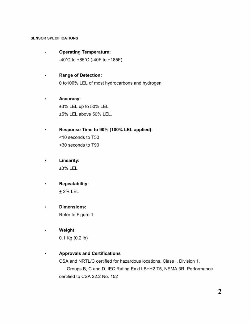
SENSOR SPECIFICATIONS
< Operating Temperature:
-40/C to +85/C (-40F to +185F)
< Range of Detection:
0 to100% LEL of most hydrocarbons and hydrogen
< Accuracy:
±3% LEL up to 50% LEL
±5% LEL above 50% LEL.
< Response Time to 90% (100% LEL applied):
<10 seconds to T50
<30 seconds to T90
< Linearity:
±3% LEL
< Repeatability:
+ 2% LEL
< Dimensions:
Refer to Figure 1
< Weight:
0.1 Kg (0.2 lb)
< Approvals and Certifications
CSA and NRTL/C certified for hazardous locations. Class I, Division 1,
Groups B, C and D. IEC Rating Ex d IIB+H2 T5, NEMA 3R. Performance
certified to CSA 22.2 No. 152

3
< Enclosure Material:
Aluminum (Optional Stainless Steel)
CONTROLLER SPECIFICATIONS
< Operating Voltage Range:
10.5 to 32.0 V dc
< Power Consumption (at 24 V dc):
Nominal (100 mA, 2.4 Watts) Maximum (200 mA, 4.8 Watts)
< Operating Temperature:
-40/C to +85/C (-40F to +185F)
< Weight:
0.9 Kg (2.0 lb)
< Approvals and Certifications:
CSA and NRTL/C certified for hazardous locations. Class I, Division 1,
Groups C and D. IEC Rating Ex d IIB T5
Option Housing for Class 1, Division 1, Group B - UT-B2-NL-SC1100
NOTE: Electronics only - CSA and NRTL/C certified for hazardous
locations Class I, Division 2 Groups B, C and D pending.

4
Figure 1 - Enclosure Dimensions
< Current Output:
4 to 20 mA - Into a maximum loop impedance of 800 Ohms at 32 V dc or 150 Ohms at
10.5 V dc. Isolated or non-isolated loop supply

5
Unit II SYSTEM INSTALLATION
INSTALLATION
Location of Sensors
There are no absolute rules for determining the quantity and location of gas detection heads to
protect any particular facility. Locate the sensors carefully in all areas where gas may escape
and where it is desirable to detect the presence of unwanted gas. Use redundancy where
enhanced protection or reliability is desired. Light gases such as methane tend to rise while
heavy gases such as propane tend to accumulate in low areas. Seek advice from experts who
know the characteristics of the gas being detected, air movement patterns and the facility. Use
common sense and refer to various publications that discuss general guidelines for your
industry.
Unpacking
The housing and terminal board are a single assembly to which the sensor is wired.
Mounting
The housing should be oriented so that the sensor is on the under-side of the housing. Use a
conduit seal and conduit loop or trap on the field wiring side to prevent water or condensation
from entering the housing through the conduit or its threaded connection.
Wiring
NOTE: Before opening the detector ensure that the area has been declassified, or
remove power from the unit.
NOTE: Since all modern electronic equipment can be damaged by static electricity
discharge it is important to discharge static electricity from your body by touching a
grounded metal object before handling the module.
NOTE: The wiring procedures in this manual are intended to ensure proper functioning
of the device under normal conditions. However, because of the many variations in
wiring codes and regulations, total compliance to these ordinances cannot be
guaranteed. Be certain that all wiring complies with applicable regulations that relate to
the installation of electrical equipment in a hazardous area. If in doubt, consult a
qualified official before wiring the system.

6
The use of shielded cable is highly recommended for any signal wires to protect against
interference caused by extraneous electrical 'noise'. This includes power and current outputs;
relay outputs do not require shielded cable. In applications where the wiring cable is installed in
conduit, the conduit must not be used for wiring to other electrical equipment.
The maximum distance between the sensor and controller is limited by the resistance of the
connecting wiring, which is a function of the gauge of the wire being used. Refer to the manuals
on the sensors used (and transmitters if used) for maximum wiring distances and wiring
instructions.
NOTE: The controller contains semiconductor devices that are susceptible to damage by
electrostatic discharge. An electrostatic charge can build up on the skin and discharge
when an object is touched. Therefore, use caution when handling, taking care not to
touch the terminals or electronic components. For more information on proper
handling, refer to the Appendix.
Water-proof and explosion-proof conduit seals are recommended to prevent water
accumulation within the enclosure. Seals should be located as close to the device as possible
and not more than 18 inches (46 cm) away. Explosion-proof installations may require an
additional seal where conduit enters a non-hazardous area. Conform to local wiring codes.
When pouring a seal, use a fibre dam to assure proper formation of the seal. The seals should
never be poured at temperatures below freezing.
The jacket and shielding of the cable should be stripped back to permit the seal to form around
the individual wires. This will prevent air, gas and water leakage through the inside of the shield
and into the enclosure.
It is recommended that explosion-proof drains and conduit breathers be used. In some
applications, alternate changes in temperature and barometric pressure can cause 'breathing'
which allows moist air to enter and circulate inside the conduit. Joints in the conduit system are
seldom tight enough to prevent this 'breathing'.
Refer to applicable wiring codes when installing and wiring. After the field wiring has been
carefully connected, check that the correct wires are connected to the corresponding terminals
and that voltage levels do not exceed the specifications. When the wiring and voltages have
been verified remove power form the system. Set the Display board back in place and tighten
the two retaining screws.
Sensor Separation
The sensor can be installed and wired directly to the Uni-Tran housing and terminal board as
per the wiring diagram or it may be remotely mounted using a sensor separation kit (CB4)
which is composed of a junction box and terminal strip. The sensor and kit are then connected
to the Uni-Tran. Use a minimum of 18 AWG shielded copper instrument wire for
separations up to 50 feet and 16 AWG for separations up to 75 feet. Consult factory if
greater separations are required (see Figure 5).

7
Figure 2 - Uni-Tran Basic Terminal Arrangement
Current Output
With power applied during the first 90 seconds the analog output will be at 3.0 mA and then
change to 4.0 mA. If after the 90 seconds warm-up the current is at 2.5 mA or any value other
than 4.0 mA then the sensor requires calibration and the calibration procedure must be initiated.
Observation of the output current levels aid the operator when calibrating the sensor/transmitter
as described below under CALIBRATION.

8
Figure 3 - Uni-Tran Terminal Connection for Non-isolatedCurrent Output
Figure 4 - Uni-Tran Basic Functionality

9
Figure 5 - Wiring Diagram with Sensor Separation

10
ANALOG OUTPUT
The analog output is precisely controlled by the internal micro-processor and digital to analog
converter. Digital control provides the means to include extra features such as the automatic
calibration, latching output signals and SensorGuard feature.
IMPORTANT:
When exposed to very high concentrations of combustible gas, Pellistor type LEL
sensors initially respond to a level greater than 60% LEL. The response can then return
to zero due to oxygen deprivation even though dangerous concentrations of gas remain
present. For this reason it is important that external monitoring devices have an alarm
latching function when connected to non-latching LEL sensors. The latching alarm must
be set to latch at a level not greater than 60% LEL. The latched monitor must remain
latched until manually reset.
When the gas signal exceeds 100% LEL the analog output is latched at 20 mA and the status
LED is showing solid red until manually reset. At the same time the SensorGuard feature is
activated to protect the sensor from damage that can be caused by the oxidation of high gas
concentrations. This protective feature extends the useful lifetime of the sensor and reduces or
eliminates disruption of its calibration. As an extra safety precaution the system should be
checked for accuracy after such over-range exposure and if necessary re-calibrate.
Reset of the latched output is performed by either of 2 methods.
< press the internal reset button for 1 second
< momentarily interrupt power to the unit
SENSOR DRIFT
It is a normal characteristic of catalytic bead type sensors to exhibit a slow drift from zero.
When the amount of drift exceeds 10% since the last calibration, the analog output switches to
a value of 2.5 mA or 4.4 mA and the LED flashes red until manually reset and the system re-
calibrated. When switched to 2.5 mA or 4.4 mA due to drift, the sensor will still respond and
transmit reasonable analog signals if gas is present.
SENSOR LIFE
Sensor life is substantially extended and calibrations reduced by the SensorGuard software
feature. Actual life is dependant on individual application conditions. In clean air applications
sensor life can often exceed 5 years.
Sensor response normally deteriorates slowly over a period of several years, depending on
exposure, until there is no longer sufficient signal. When this condition occurs, calibration will
not be possible, the analog output will lock at 2.5 mA and the status LED flashes red. Install a
new sensor and re-calibrate. The calibration function automatically adjusts span amplifier gain
across a broad range without any need for manual adjustment of potentiometers or jumpers.
11
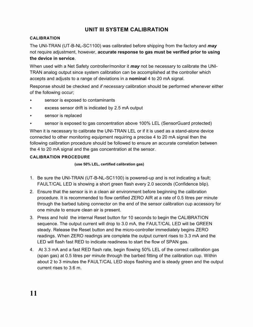
UNIT III SYSTEM CALIBRATION
CALIBRATION
The UNI-TRAN (UT-B-NL-SC1100) was calibrated before shipping from the factory and may
not require adjustment, however, accurate response to gas must be verified prior to using
the device in service.
When used with a Net Safety controller/monitor it may not be necessary to calibrate the UNI-
TRAN analog output since system calibration can be accomplished at the controller which
accepts and adjusts to a range of deviations in a nominal 4 to 20 mA signal.
Response should be checked and if necessary calibration should be performed whenever either
of the following occur;
< sensor is exposed to contaminants
< excess sensor drift is indicated by 2.5 mA output
< sensor is replaced
< sensor is exposed to gas concentration above 100% LEL (SensorGuard protected)
When it is necessary to calibrate the UNI-TRAN LEL or if it is used as a stand-alone device
connected to other monitoring equipment requiring a precise 4 to 20 mA signal then the
following calibration procedure should be followed to ensure an accurate correlation between
the 4 to 20 mA signal and the gas concentration at the sensor.
CALIBRATION PROCEDURE
(use 50% LEL, certified calibration gas)
1. Be sure the UNI-TRAN (UT-B-NL-SC1100) is powered-up and is not indicating a fault;
FAULT/CAL LED is showing a short green flash every 2.0 seconds (Confidence blip).
2. Ensure that the sensor is in a clean air environment before beginning the calibration
procedure. It is recommended to flow certified ZERO AIR at a rate of 0.5 litres per minute
through the barbed tubing connector on the end of the sensor calibration cup accessory for
one minute to ensure clean air is present.
3. Press and hold the internal Reset button for 10 seconds to begin the CALIBRATION
sequence. The output current will drop to 3.0 mA, the FAULT/CAL LED will be GREEN
steady. Release the Reset button and the micro-controller immediately begins ZERO
readings. When ZERO readings are complete the output current rises to 3.3 mA and the
LED will flash fast RED to indicate readiness to start the flow of SPAN gas.
4. At 3.3 mA and a fast RED flash rate, begin flowing 50% LEL of the correct calibration gas
(span gas) at 0.5 litres per minute through the barbed fitting of the calibration cup. Within
about 2 to 3 minutes the FAULT/CAL LED stops flashing and is steady green and the output
current rises to 3.6 m.

12
(If span setting does not complete successfully within five minutes of starting the calibration
sequence the status LED alternates flashes of RED and GREEN and the analog output
changes back and forth from 3.0 to 3.3 mA. The unit remains in this state until acknowledged
by a manual Reset. After manual Reset the program will return to the normal operation mode
using previous calibration values. Since the calibration was unsuccessful another attempt may
be made or replace the sensor and re-try calibration.)
5. When the status LED is solid green and the analog output switches to 3.6 mA span setting
is complete. Stop the flow of calibration gas and disconnect the hose from the barbed fitting
of the calibration cup. When sensor response level falls to about 7% LEL (5.2 mA), the
output current is restored to normal operation and the LED is returned to its normal
confidence blip; fast red flash every 2.0 seconds changing to fast green flash when sensor
response returns to zero. Release the Reset button and the micro-controller immediately
begins its calibration sequence.
SENSOR POISONS and INHIBITORS
The Net Safety sensor provides excellent resistance to poisoning but any catalytic sensor may
be adversely affected when exposure is prolonged or intense.
Poisoning can be caused by compounds containing lead, sulphur, silicones and phosphates
which can permanently reduce sensitivity of the sensor.
Temporary inhibition of response can be caused by compounds such as H2S and halogenated
hydrocarbons. Recovery can occur after a period of operation in clean air.
When a known exposure to poisons or inhibitors occurs, the sensor/transmitter should be
checked for accurate response and if necessary re-calibrate.
13
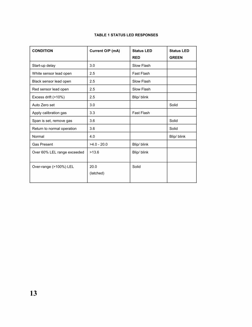
TABLE 1 STATUS LED RESPONSES
CONDITION Current O/P (mA) Status LED
RED
Status LED
GREEN
Start-up delay 3.0 Slow Flash
White sensor lead open 2.5 Fast Flash
Black sensor lead open 2.5 Slow Flash
Red sensor lead open 2.5 Slow Flash
Excess drift (>10%) 2.5 Blip/ blink
Auto Zero set 3.0 Solid
Apply calibration gas 3.3 Fast Flash
Span is set, remove gas 3.6 Solid
Return to normal operation 3.6 Solid
Normal 4.0 Blip/ blink
Gas Present >4.0 - 20.0 Blip/ blink
Over 60% LEL range exceeded >13.6 Blip/ blink
Over-range (>100%) LEL 20.0
(latched)
Solid

14
IMPORTANT NOTICE
Because all catalytic type combustible gas sensors require normal oxygen levels to be present
in order to give accurate readings, there could be situations where the sensor indicates safe
gas levels when in fact there is a dangerously high level of gas present at the sensor.
The Net Safety UNI-TRAN LEL is equipped with a proprietary signal processor to prevent
the user from being presented with such false and potentially dangerous signals.
If the signal exceeds 20 mA or 100% LEL, the current is latched at 20 mA until manually reset.
When this high level signal is present it is mandatory that the area around the sensor be
considered dangerous even though there is a possibility that the atmosphere has returned to a
safe condition.
It is necessary that reliable monitoring and indicating devices or systems be connected to the
transmitter. These devices must be designed to produce clear visual and audible danger
signals when high signal levels occur. Operating personnel must consider the area to be
dangerous until a careful survey of the area has been conducted with a separate and reliable
gas indicating device. Only after the area is confirmed to free of dangerous gas levels is it
allowable to RESET the combustible gas transmitter to resume normal operation.
CAUTION
Any catalytic type combustible gas sensor is susceptible to damage when exposed to high
levels of gas, therefore, check the sensor for accurate response and if necessary perform a
calibration or replace the sensor after any high level alarm. If the high level response resulted in
a latched 20 mA alarm signal then the sensor/transmitter will require a normal warm-up period
after it is reset before its accuracy can be assessed and a calibration performed.
SENSOR PROTECTION
To minimize damage to the sensor that can be caused by extended exposure to high
concentrations of gas, the Net Safety combustible gas transmitter is equipped with a proprietary
signal processor which invokes SensorGuard when detected levels exceed 100% LEL and the
output signal is latched at 20 mA until manually reset (after verifying the area is safe).
CAUTION: FOR SAFETY REASONS THIS EQUIPMENT MUST BE OPERATED AND
SERVICED BY QUALIFIED PERSONNEL ONLY. READ AND UNDERSTAND
INSTRUCTION MANUAL COMPLETELY BEFORE OPERATING OR SERVICING.
ATTENTION: POUR DES RAISONS DE SECURITE, CET EQUIPMENT DOIT ETRE
UTILISE, ENTRETENU ET REPARE UNIQUEMENT PAR UN PERSONNEL
QUALIFIE. ETUDIER LE MANUEL.

15
How to Return EquipmentA Material Return Authorization number is required in order to return equipment. Please contact
Net Safety Monitoring at (403) 219-0688 before returning equipment or consult our Service
Department to possibly avoid returning equipment.
If you are required to return equipment, include the following information:
1. A Material Return Authorization number (provided over the phone to you by Net Safety).
2. A detailed description of the problem. The more specific you are regarding the problem,
the quicker our Service department can determine and correct the problem.
3. A company name, contact name and telephone number.
4. A Purchase Order, from your company, authorizing repairs or request for quote.
5. Ship all equipment, prepaid to:
Net Safety Monitoring Inc
2721 Hopewell Place NE
Calgary, Alberta, Canada
T1Y 7J7
6. Mark all packages: RETURN for REPAIR
Waybills, for shipments from outside Canada, must state:
Equipment being returned for repair
All charges to be billed to the sender
Also, please ensure a duplicate copy of the packing slip is enclosed inside the box indicating
item 1-4 along with the courier and account number for returning the goods.
All Equipment must be Shipped prepaid. Collect shipments will not be accepted.
Pack items to protect them from damage and use anti-static bags or aluminum-backed
cardboard as protection from electrostatic discharge.

16
*Published in Accordance with E1A standard 471
Appendix A ELECTROSTATIC SENSITIVE DEVICE (ESD)
Electrostatic discharge (ESD) is the transfer, between bodies, of an electrostatic charge
caused by direct contact or induced by an electrostatic field.
The most common cause of ESD is physical contact. Touching an object can cause a
discharge of electrostatic energy—ESD! If the charge is sufficient and occurs near
electronic components, it can damage or destroy those components.
In some cases, damage is instantaneous and an immediate malfunction occurs.
However, symptoms are not always immediate—performance may be marginal or
seemingly normal for an indefinite period of time, followed by a sudden failure.
To eliminate potential ESD damage, review the following guidelines:
Handle boards by metal shields—taking care not to touch electronic components
Wear grounded wrist or foot straps, or ESD shoes or heel grounders to dissipate
unwanted static energy
Prior to handling boards, dispel any charge in your body or equipment
Enure components are transported and stored in static safe packaging
When returning boards, carefully package in the original carton and static protective
wrapping
Ensure ALL personnel are educated and trained in ESD Control Procedures
In general, exercise accepted and proven precautions normally observed when
handling electrostatic sensitive devices.
A warning label is placed on the packaging, identifying product using electrostatic
sensitive semiconductor devices.

Appendix B Wire Resistence in OhmsDistance
(Feet)AWG #20 AWG #18 AWG #16 AWG #14 AWG #12 AWG #10 AWG #8
100 1.02 0.64 0.40 0.25 0.16 0.10 0.06
200 2.03 1.28 0.80 0.51 0.32 0.20 0.13
300 3.05 1.92 1.20 0.76 0.48 0.30 0.19
400 4.06 2.55 1.61 1.01 0.64 0.40 0.25
500 5.08 3.20 2.01 1.26 0.79 0.50 0.31
600 6.09 3.83 2.41 1.52 0.95 0.60 0.38
700 7.11 4.47 2.81 1.77 1.11 0.70 0.44
800 8.12 5.11 3.21 2.02 1.27 0.80 0.50
900 9.14 5.75 3.61 2.27 1.43 0.90 0.57
1000 10.20 6.39 4.02 2.53 1.59 1.09 0.63
1250 12.70 7.99 5.03 3.16 1.99 1.25 0.79
1500 15.20 9.58 6.02 3.79 2.38 1.50 0.94
1750 17.80 11.20 7.03 4.42 2.78 1.75 1.10
2000 20.30 12.80 8.03 5.05 3.18 2.00 1.26
2250 22.80 14.40 9.03 5.68 3.57 2.25 1.41
2500 25.40 16.00 10.00 6.31 3.97 2.50 1.57
3000 30.50 19.20 12.00 7.58 4.76 3.00 1.88
3500 35.50 22.40 14.10 8.84 5.56 3.50 2.21
4000 40.60 25.50 16.10 10.00 6.35 4.00 2.51
4500 45.70 28.70 18.10 11.40 7.15 4.50 2.82
5000 50.10 32.00 20.10 12.60 7.94 5.00 3.14
5500 55.80 35.10 22.10 13.91 8.73 5.50 3.46
6000 61.00 38.30 24.10 15.20 9.53 6.00 3.77
6500 66.00 41.50 26.10 16.40 10.30 6.50 4.08
7000 71.10 44.70 28.10 17.70 11.10 7.00 4.40
7500 76.10 47.90 30.10 19.00 12.00 7.49 4.71
8000 81.20 51.10 23.10 20.20 12.70 7.99 5.03
9000 91.40 57.50 36.10 22.70 14.30 8.99 5.65
10 000 102.00 63.90 40.20 25.30 15.90 9.99 6.28
NOTE: RESISTANCE SHOWN IS ONE WAY. THIS FIGURE SHOULD BE DOUBLED WHEN DETERMINING
CLOSED LOOP RESISTANCE.


Distributed By:
2721 Hopewell Place NE
Calgary, Alberta, Canada T1Y 7J7
Telephone: (403) 219-0688 Fax: (403) 219-0694
www.net-safety.com
E-mail: [email protected]