gss series combustible gas sensor transmitter operator… · gss series combustible gas sensor...
TRANSCRIPT
MINT-0290-XX Rev. A
Released: 01/30/08
GSS SERIES
Combustible Gas Sensor Transmitter
Operator’s Manual

MINT-0290-XX Rev. A : 01/30/08 2
Product Warranty
Matheson Tri-Gas, warrants gas alarm equipment sold by us to be free from defects in materials,
workmanship, and performance for a period of one year from date of shipment from Matheson Tri-Gas
Any parts found defective within that period will be repaired or replaced, at our option, free of charge.
This warranty does not apply to those items which by their nature are subject to deterioration or
consumption in normal service, and which must be cleaned, repaired, or replaced on a routine basis.
Examples of such items are:
a) Absorbent cartridges d) Batteries
b) Pump diaphragms and valves e) Filter elements
c) Fuses
Warranty is voided by abuse including mechanical damage, alteration, rough handling, or repair
procedures not in accordance with the operator’s manual. This warranty indicates the full extent of our
liability, and we are not responsible for removal or replacement costs, local repair costs, transportation
costs, or contingent expenses incurred without our prior approval.
THIS WARRANTY IS EXPRESSLY IN LIEU OF ANY AND ALL OTHER WARRANTIES AND
REPRESENTATIONS, EXPRESSED OR IMPLIED, AND ALL OTHER OBLIGATIONS OR
LIABILITIES ON THE PART OF MATHESON TRI-GAS, INCLUDING BUT NOT LIMITED TO,
THE WARRANTY OF MERCHANTABILITY OR FITNESS FOR A PARTICULAR PURPOSE. IN
NO EVENT SHALL MATHESON TRI-GAS, BE LIABLE FOR INDIRECT, INCIDENTAL, OR
CONSEQUENTIAL LOSS OR DAMAGE OF ANY KIND CONNECTED WITH THE USE OF ITS
PRODUCTS OR FAILURE OF ITS PRODUCTS TO FUNCTION OR OPERATE PROPERLY.
This warranty covers instruments and parts sold to users by authorized distributors, dealers, and
representatives as appointed by Matheson Tri-Gas
We do not assume indemnification for any accident or damage caused by the operation of this gas
monitor, and our warranty is limited to the replacement of parts or our complete goods.

MINT-0290-XX Rev. A : 01/30/08 3
Table Of Contents
Overview 4
Specifications 4
Description 5
Combustible Gas Detector
5
Amplifier
6
Junction Box
6
Installation 7
Mounting the Combustible Gas Transmitter
7
Wiring the Combustible Gas Transmitter
8
Startup 10
Introducing Incoming Power
10
Setting the Zero Signal
10
Maintenance 11
Preventive Maintenance
11
Troubleshooting
13
Replacing Components of the Combustible Gas Transmitter
13
Calibration 16
Preparing for Calibration
16
Setting the Zero Reading
16
Setting the Response Reading
17
Returning to Normal Operation
17
Parts List 18
MINT-0290-XX Rev. A : 01/30/08 4
Overview
This manual describes the GSS Series combustible gas transmitter. This manual also describes how
to install, start up, configure, maintain, and calibrate the transmitter when it is used with a gas
monitoring controller. A parts list at the end of this manual lists replacement parts and accessories
for the combustible gas transmitter.
Specifications
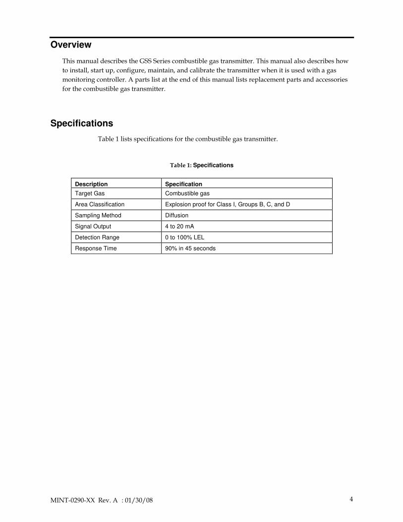
Table 1 lists specifications for the combustible gas transmitter.
Table 1: Specifications
Description Specification
Target Gas Combustible gas
Area Classification Explosion proof for Class I, Groups B, C, and D
Sampling Method Diffusion
Signal Output 4 to 20 mA
Detection Range 0 to 100% LEL
Response Time 90% in 45 seconds

MINT-0290-XX Rev. A : 01/30/08 5
Description
This section describes the components of the combustible gas transmitter. The transmitter is a 4 - 20
mA type detector head. It consists of the combustible gas detector, amplifier, and junction box.
Combustible Gas Detector
The combustible gas detector includes the sensing elements, flame arrestor, detector housing, and detector leads.
Sensing elements
Two sensing elements are protected within the detector assembly. Through a series of thermal and
electronic reactions, these elements produce an electrical output that is proportional to the detection
range of the transmitter.
Flame arrestor
The porous flame arrestor allows the target gas to diffuse into the detector assembly and contact the
sensing elements. The flame arrestor also contains sparks within the detector.
Detector housing
The sensing elements and flame arrestor are installed within the detector housing. Mounting
threads (1/2 in. NPT) at the top of the detector allow you to mount the combustible gas detector
into the bottom conduit hub of the junction box. A rainshield screws onto the bottom of the
detector. The rainshield helps protect the detector from debris in the monitoring environment.
Detector leads
Four color-coded leads extend from the top of the detector. The leads allow you to connect the
combustible gas detector to the amplifier.

MINT-0290-XX Rev. A : 01/30/08 6
Amplifier
The amplifier converts the electrical output from the detector to a 4 to 20 mA signal that is
proportional to the detection range and transmits the signal to a gas monitoring controller. The
amplifier includes the interconnect terminal strip, span potentiometer, zero potentiometer, and test
points (see Figure 1).
Interconnect terminal strip
The interconnect terminal strip is a seven-point terminal strip. Use the interconnect terminal strip to
connect the combustible gas detector to the amplifier and the amplifier to a controller.
NOTE: The combustible gas detector is factory-wired to the amplifier. See the Installation section of
this manual for all wiring procedures related to the transmitter.
Span potentiometer
The span potentiometer is near the bottom of the amplifier (see Figure 1). Use the span
potentiometer to adjust the transmitter’s response output during the calibration procedure.
Zero potentiometer
The zero potentiometer is to the right of the span potentiometer (see Figure 1). Use the zero
potentiometer to adjust the transmitter’s target gas-free output during the start-up and calibration
procedures.
CAUTION: The amplifier includes two additional potentiometers. They are factory-set. Do not adjust them.
Test points
The test points (labeled TP+ and TP-) are to the left of the interconnect terminal strip
(see Figure 1). The test points produce a 100 to 500 mV output that is proportional to the
transmitter’s 4 to 20 mA output. Use the test points and a voltmeter to measure the transmitter’s
output during the start-up and calibration procedures.
Junction Box
Use the junction box to install the combustible gas transmitter at a mounting site that is remote from
the controller. The junction box also protects the amplifier and wiring connections made to the
amplifier. Use the two 3/4 in. conduit hubs to mount the detector to the junction box (bottom hub)
and connect wiring from the amplifier to the controller (top hub). The detector has 1/2 in. NPT
mounting threads, so a 3/4 in NPT. x 1/2 in. NPT reducer is used to mount it.
NOTE: The combustible gas detector and amplifier are factory-mounted to the
junction box.
Use the junction box’s two mounting holes to mount the combustible gas transmitter to a vertical
surface at the monitoring site. Use the cover on the front of the junction box to access the interior of
the junction box.

MINT-0290-XX Rev. A : 01/30/08 7
Installation
This section describes procedures to mount the combustible gas transmitter in the monitoring
environment and wire the transmitter to the controller.
Mounting the Combustible Gas Transmitter
1. Select a mounting site that is representative of the monitoring environment. Consider the
following when you select the mounting site.
• Select a site where the transmitter is not likely to be bumped or disturbed. Make sure there
is sufficient room to perform start-up, maintenance, and calibration procedures.
• Select a site where the target gas is likely to be found first. For lighter gases, mount the
detector near the ceiling; for heavier gases, mount the detector near the floor.
If the combustible gas detector is mounted to the junction box, skip to step 5. If not, continue with
step 2.
2. Remove the junction box cover.
3. Guide the four wires that extend from the top of the combustible gas detector through the
bottom conduit hub of the junction box.
4. Screw the combustible gas detector into the bottom conduit hub of the junction box.
5. At the monitoring site, use #10 screws through the junction box’s two mounting holes to secure
the junction box to a vertical surface.
CAUTION: Mount the combustible gas transmitter with the detector facing down (see Figure .)

MINT-0290-XX Rev. A : 01/30/08 8
Wiring the Combustible Gas Transmitter to a Controller
WARNING: Always verify that the power source is off before you make wiring connections.
1. Turn off power to the controller.
2. Place the controller’s power switch in the OFF position.
3. Remove the junction box cover.
4. Verify that the detector leads are wired to the amplifier’s interconnect terminal strip.
If necessary, connect the detector leads to the interconnect terminal strip as shown in Figure 1.
5. Guide a three-conductor, shielded cable or three wires in conduit through the top conduit hub
of the junction box.
6. Connect the three wires to the interconnect terminal strip as follows (see Figure 3).
• Connect the positive wire to the 24VDC terminal.
• Connect the feedback wire to the 4-20 (FB) terminal.
• Connect the negative wire to the DC - terminal.
CAUTION: If shielded cable is used, leave the cable shield’s drain wire insulated and disconnected at the
transmitter. You will connect the opposite end of the cable’s drain wire at the controller to
chassis ground.
7. Secure the junction box cover to the junction box.
8. Route the cable or wires leading from the combustible gas transmitter through one of the
conduit hubs at the controller housing.
CAUTION: Do not route power and transmitter wiring through the same conduit hub. The power cable
may disrupt the transmission of the transmitter signal to the controller.
9. Connect the wires to the applicable transmitter terminal strip at the controller as shown in
Figure 3 below. If shielded cable is used, connect the cable’s drain wire to an available chassis
ground at the controller.

MINT-0290-XX Rev. A : 01/30/08 9

MINT-0290-XX Rev. A : 01/30/08 10
Start Up
This section describes procedures to start up the combustible gas transmitter and place the
transmitter into normal operation.
Introducing Incoming Power
1. Complete the installation procedures described earlier in this manual.
2. Verify that the power wiring to the controller is correct and secure. Refer to the controller
instruction manual.
3. Turn on or plug in power to the controller, then place the controller’s power switch in the ON
position.
4. Verify that the controller is on and operating properly. Refer to the controller operator’s
manual.
CAUTION: Allow the detector to warm up for 5 minutes before you continue with the next section, “Setting
the Zero Signal.”
Setting the Zero Signal
CAUTION: If you suspect the presence of combustible gas in the monitoring environment, use the
calibration kit and the zero air calibration cylinder to introduce “fresh air” to the detector and
verify an accurate zero setting.
1. Verify that the transmitter is in a fresh air environment (environment known to be free of
combustible gas).
2. Unscrew and remove the junction box cover from the junction box.
3. Set a voltmeter to measure in the millivolt (mV) range.
4. Plug the voltmeter leads into the test points on the amplifier. Plug the positive lead into the test
point labeled TP+; plug the negative lead into the test point labeled TP-.
5. Verify a voltmeter reading of 100 mV (±2 mV).
6. If necessary, use a flat-blade screwdriver to adjust the zero potentiometer until the voltmeter
reading is 100 mV (±2 mV).
7. Secure the junction box cover to the junction box.

MINT-0290-XX Rev. A : 01/30/08 11
Maintenance
This section describes maintenance procedures. It includes preventive maintenance,
troubleshooting, and component replacement procedures.
Preventive Maintenance
This section describes a preventive maintenance schedule to ensure the optimum performance of
the combustible gas transmitter. It includes daily, monthly, and quarterly procedures.
Daily
Verify a display reading of 0% LEL at the controller. Investigate significant changes in the display
reading.
Monthly
This procedure describes a test to verify that the combustible gas transmitter responds properly to
the target gas. It describes a test using a fixed flow regulator that has no on/off knob and allows
sample gas to flow as soon as it is screwed onto a cylinder. Matheson Tri-Gas recommends using a
0.5 LPM (liters per minute) fixed flow regulator.
NOTE: To avoid wasting gas, do not leave the fixed flow regulator installed on a cylinder when it
is not being used.
NOTE: Performing a response test on the combustible transmitter may cause alarms. Be sure to put
the controller into its calibration program or disable external alarms before performing this
test
Preparing for the response test
1. Place the controller into its calibration program or disable external alarms.
2. Verify that the controller display reading for the channel you are testing is 0 %LEL.
i. If the display reading is not zero, set the zero reading of the transmitter as described in
“ Start Up” on page 10 of this manual, then continue this procedure.
3. Screw the calibration cup onto the bottom of the combustible detector.
4. Use the calibration kit sample tubing to connect the regulator to the calibration cup.
NOTE: Do not screw the regulator into the calibration cylinder at this time.
5. Set a voltmeter to measure in the millivolt (mV) range.
6. Remove the junction box cover, then plug the voltmeter leads into the test points on the
amplifier.
7. Plug the positive lead into the test point labeled TP+; plug the negative lead into the test
point labeled TP
8. Use the following formula to determine the correct test points output for the test sample.
Output (mV) = (calibrating sample/fullscale) x 400 + 100
For example, with a test sample of 50% LEL and a fullscale setting of 100% LEL, the correct
output is 300 mV.
300 (mV) = (50/100) X 400 +100

MINT-0290-XX Rev. A : 01/30/08 12
Performing the response test
1. Screw the regulator into the calibration cylinder. The sample gas will begin to flow.
2. Allow the gas to flow for two minutes, then verify that the reading is within ± 10% of the
response reading you determined earlier.
NOTE: If the reading is not within ± 10% of the correct response reading, calibrate the
transmitter as described in “ Calibration” on page 16 of this manual.
3. Unscrew the regulator from the calibration cylinder.
4. Unscrew the calibration cup from the detector.
5. Remove the voltmeter leads from the amplifier test points.
6. Reinstall the junction box cover.
7. When the controller display reading falls below the alarm setpoints, return the controller to
normal operation.
Quarterly
Calibrate the combustible gas transmitter as described in “ Calibration” on page 17 of this manual.

MINT-0290-XX Rev. A : 01/30/08 13
Troubleshooting
The troubleshooting guide describes symptoms, probable causes, and recommended action for
problems you may encounter with the combustible gas transmitter.
NOTE: This troubleshooting guide describes transmitter problems only. See the controller
operator’s manual for problems you may encounter with the controller.
Condition Symptom(s) Probable Causes Recommended Action
Fail Condition • Controller indicates
a fail condition.
• The transmitter wiring
is disconnected or
misconnected.
• The transmitters zero
reading is low enough to
cause a fail condition.
• The transmitter is
malfunctioning.
1. Verify that the transmitter wiring is
correct and secure.
2. Calibrate the transmitter.
3. If the fail condition continues, replace
the detector.
4. If the fail condition continues, contact
RKI for further instruction.
Slow or No
Response/
Difficult or
Unable to
Calibrate
• Transmitter
responds slowly or
does not respond to
response test.
• Unable to accurately
set the zero or
response reading
during calibration.
• Transmitter requires
frequent calibration.
Note: Under “normal”
circumstances, the
transmitter requires
calibration once every
three months.
Some applications may
require a more frequent
calibration schedule.
• The calibration
cylinder is low, out-
dated, or defective.
• The transmitter is
malfunctioning.
5. Verify that the calibration cylinder
contains an adequate supply of a fresh
test sample.
6. Verify that the regulator used for
calibration is a 0.5 LPM regulator.
7. If the calibration/response difficulties
continue, replace the detector.
8. If the calibration/response difficulties
continue, contact RKI for further
instruction.
Replacing Components of the Combustible Gas Transmitter
This section includes procedures to replace the combustible gas detector sensor and amplifier.
Replacing the combustible gas detector sensor
1. Turn off power to the controller.
2. Place the controller’s power switch in the OFF position.
3. Remove the junction box cover.
4. Disconnect the sensor leads from the interconnect terminal strip. Note the position of the color-
coded leads as you remove them.
5. Unscrew the sensor from the junction box.
6. Guide the sensor leads of the replacement sensor through the bottom conduit hub of the
junction box, then screw the mounting threads of the sensor into the conduit hub.

MINT-0290-XX Rev. A : 01/30/08 14
7. Connect the sensor leads to the interconnect terminal strip as shown in Table 2 below and
Figure 3 on page 9 of this manual.
Table 2
Sensor Lead Amplifier Interconnect
Terminal Strip
Red RED
White WHT
Green GRN
Black BLK
8. Turn on power to the controller.
9. Place the controller’s power switch in the ON position.
CAUTION: Allow the replacement detector to warm up for 5 minutes before you continue with the next step.
10. Calibrate the replacement detector as described in “ Calibration” on page 16 of this manual.
Replacing the amplifier
1. Turn off power to the controller
2. Place the controller’s power switch in the OFF position.
3. Remove the junction box cover.
4. Disconnect the sensor leads from the interconnect terminal strip.
5. Disconnect the wiring that connects the combustible gas transmitter to the controller from the
amplifier’s interconnect terminal strip.
6. Unscrew and remove the two screws that secure the amplifier to the junction box.
The screws are at the top left and bottom right of the amplifier.
7. Remove the amplifier.
8. Place the new amplifier in the same position as the amplifier you removed in the previous step.
9. Use the two screws you removed in step 6 to secure the amplifier to the junction box.
10. Reconnect the wiring that connects the controller to the combustible gas transmitter at the
amplifier’s interconnect terminal strip as shown in Table 3 below and Figure 3 on page 9 of
this manual.
11. Reconnecting the Combustible Gas Amplifier to the Controller
Table 3
Amplifier Interconnect
Terminal Strip
Controller Transmitter
Terminal Strip (typical)
GND - (DC -)
4-20 4 - 20 mA (FB or S)
24V + 24V
12. Reconnect the detector leads to the amplifier’s interconnect terminal strip as shown in Table 4
below and Figure 3 on page 9 of this manual.

MINT-0290-XX Rev. A : 01/30/08 15
13. Connect the sensor leads to the interconnect terminal strip as shown in Table 2 above and Figure 3 on
page 9 of this manual.
14. Turn on power to the controller.
15. Turn on the controller and place it into normal operation.
CAUTION: Allow the detector to warm up for 5 minutes before you continue with the next step.
16. Calibrate the combustible gas transmitter as described in “ Calibration” on page 16 of this
manual.
MINT-0290-XX Rev. A : 01/30/08 16
Calibration
This section describes how to calibrate the combustible gas transmitter. It includes procedures to
prepare for calibration, set the zero reading, set the response reading, and return to normal operation.
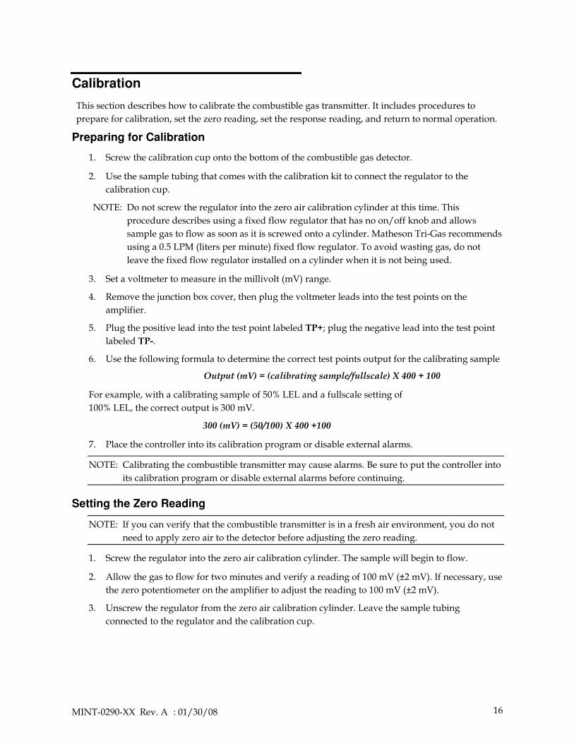
Preparing for Calibration
1. Screw the calibration cup onto the bottom of the combustible gas detector.
2. Use the sample tubing that comes with the calibration kit to connect the regulator to the
calibration cup.
NOTE: Do not screw the regulator into the zero air calibration cylinder at this time. This
procedure describes using a fixed flow regulator that has no on/off knob and allows
sample gas to flow as soon as it is screwed onto a cylinder. Matheson Tri-Gas recommends
using a 0.5 LPM (liters per minute) fixed flow regulator. To avoid wasting gas, do not
leave the fixed flow regulator installed on a cylinder when it is not being used.
3. Set a voltmeter to measure in the millivolt (mV) range.
4. Remove the junction box cover, then plug the voltmeter leads into the test points on the
amplifier.
5. Plug the positive lead into the test point labeled TP+; plug the negative lead into the test point
labeled TP-.
6. Use the following formula to determine the correct test points output for the calibrating sample
Output (mV) = (calibrating sample/fullscale) X 400 + 100
For example, with a calibrating sample of 50% LEL and a fullscale setting of
100% LEL, the correct output is 300 mV.
300 (mV) = (50/100) X 400 +100
7. Place the controller into its calibration program or disable external alarms.
NOTE: Calibrating the combustible transmitter may cause alarms. Be sure to put the controller into
its calibration program or disable external alarms before continuing.
Setting the Zero Reading
NOTE: If you can verify that the combustible transmitter is in a fresh air environment, you do not
need to apply zero air to the detector before adjusting the zero reading.
1. Screw the regulator into the zero air calibration cylinder. The sample will begin to flow.
2. Allow the gas to flow for two minutes and verify a reading of 100 mV (±2 mV). If necessary, use
the zero potentiometer on the amplifier to adjust the reading to 100 mV (±2 mV).
3. Unscrew the regulator from the zero air calibration cylinder. Leave the sample tubing
connected to the regulator and the calibration cup.
MINT-0290-XX Rev. A : 01/30/08 17
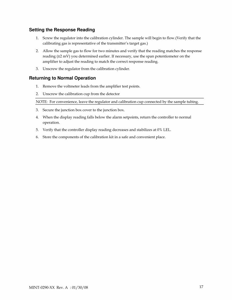
Setting the Response Reading
1. Screw the regulator into the calibration cylinder. The sample will begin to flow.(Verify that the
calibrating gas is representative of the transmitter’s target gas.)
2. Allow the sample gas to flow for two minutes and verify that the reading matches the response
reading (±2 mV) you determined earlier. If necessary, use the span potentiometer on the
amplifier to adjust the reading to match the correct response reading.
3. Unscrew the regulator from the calibration cylinder.
Returning to Normal Operation
1. Remove the voltmeter leads from the amplifier test points.
2. Unscrew the calibration cup from the detector
NOTE: For convenience, leave the regulator and calibration cup connected by the sample tubing.
3. Secure the junction box cover to the junction box.
4. When the display reading falls below the alarm setpoints, return the controller to normal
operation.
5. Verify that the controller display reading decreases and stabilizes at 0% LEL.
6. Store the components of the calibration kit in a safe and convenient place.

MINT-0290-XX Rev. A : 01/30/08 18
Parts List
Table 4 lists replacement parts and accessories for the combustible gas transmitter.
Table 4
Part Number Description
06-1248RK Sample tubing (3/16 in. x 5/16 in.; specify length when ordering)
18-0001RK Reducer, 3/4 in. NPT x 1/2 in. NPT
18-0405RK-01 Junction box (without cover; pre-drilled for amplifier)
18-0406RK Junction box cover (cover only)
57-1050RK Amplifier (specify target gas when ordering)
61-0140RK Combustible gas detector
65-2400RK Combustible gas transmitter (includes detector and amplifier; specify target gas
when ordering)
71-0060RK 65-2400RK Combustible Gas Transmitter Operator’s Manual (this document)
81-0007RK-01 Calibration cylinder (50% LEL Hexane; 34-liter)
81-0012RK-01 Calibration cylinder (50% LEL Methane; 34-liter)
81-0076RK-01 Zero air calibration cylinder (34-liter)
81-1003RK Regulator, 0.5 liter/minute; continuous flow (for 17- and 34-liter calibration
cylinders)
81-1117RK Calibration cup