underwater technology vol 31 no 2 subsea system readiness level assessment
DESCRIPTION
underwater technologyTRANSCRIPT
77
doi:10.3723/ut.31.077 International Journal of the Society for Underwater Technology, Vol 31, No 2, pp 77–92, 2013
Technic
al P
aper
Subsea system readiness level assessment
Sirous YasseriSafe Sight Technology, London, UK
AbstractBoth the American Petroleum Institute (API) 17N: 2009 and Det Norske Veritas (DNV) RP-A203 (2011) recommend that the technologies inserted into subsea installations should be assessed during design and manufacturing using a tech-nology readiness level (TRL) scale. This should be used as a measure of maturity of all the individual technologies, for qualification and readiness assurance. This paper proposes the creation of a system-based approach for managing the development of subsea systems and making effective decisions to ensure the efficient progress of the project. It recommends complementing TRL with an integration readi-ness level (IRL) scale, to address IRL between the inserted technologies, along with a system readiness level (SRL) scale to assess the overall project status. It also presents a method for combining the current TRL scale and the pro-posed new IRL scale to determine an estimate of SRL at all stages of a subsea system development. This provides a composite metric for determining the system readiness level for project delivery. The application of the new proposed scales is demonstrated using a case example.
Keywords: system readiness level (SRL), technology readi-ness level (TRL), integration readiness level (IRL), subsea technology qualification, subsea production technical risk
Acronym list
BoD basis of design: This is the system’s engineering requirements.
DP dynamic positioning DSM design structure matrixFAT factory acceptance testIRL integration readiness level
Integration is the combining of separate compo-nents into a seamless unit. This is an integra-tion-specific metric, to determine the integration readiness between two or more components, and/or subsystems (hardware and/or software).
SRL system readiness levelThis is a metric that incorporates the maturity level of the integrated system, as well as the interoperability of the entire system.
SRLest system readiness level estimateThis is the SRL estimate at a review stage, which determines the current state of the system readi-ness. It is a derived metric, which aggregates TRL and IRL of all components of a system that may be at various levels of development at a given time.
TRL technology readiness levelThis is a metric for determining technology matu-rity before incorporating into a system.
1. IntroductionTechnology readiness levels (TRLs) were first used by NASA in the 1980s as part of an overall technol-ogy risk management process. By the early 1990s, TRLs were routinely used within NASA to support technology maturity assessments and consistent comparisons of the maturity between different technologies (Mankins, 2002).
The US Department of Defense (USDOD) adopted TRL for risk assessments in 1999 (USDOD, 1998). Current USDOD guidance (2008; 2009) requires the use of TRL (or an equivalent method-ology) as part of an overall system technical risk assessment. These TRLs range from 1 to 9, with 9 signifying the highest degree of readiness and 1 the lowest.
In the UK the Ministry of Defence (MOD) adopted TRL to improve technology management to reduce the project delay. In 2007, the UK MOD updated its TRLs’ section to bring more focus to the importance of project and sub-project inter-action when conducting a TRL assessment (MOD, 2008). The MOD replaced NASA’s broad generic terms with definitions aligned to specific milestones (MOD, 2011). Because of the success of TRL, a vari-ety of other maturity metrics have been proposed as decision support tools (Bilbro, 2007), such as design readiness level; manufacturing readiness level; software readiness level; operational readi-ness level; human readiness levels; habitation read-iness level; and capability readiness levels.
Many industries have embraced the concept of TRL as a metric for measuring technology matu-rity. The American Petroleum Institute (API) RP 17N (2009) adopted TRL methodology for subsea equipment qualification and Det Norske Veritas (DNV) RP-A203 (2011) followed later. Bureau Veritas (2010) addresses the same issue using a risk-based approach. The API recommended prac-tice is now written into major petroleum compa-nies’ procedures as a tool to assess the level of progress of subsea design, fabrication and com-ponents’ qualification. Such policies require con-tractors to hold design and manufacturing reviews using TRL. Examples of TRL application to the offshore oil and gas can be found in US Mineral Management Service (MMS, 2010) and Millheim et al. (2011).E-mail address: [email protected]

Yasseri. Subsea system readiness level assessment
78
Undoubtedly, TRL is a useful tool for determining a technology’s maturity before inserting it into a sys-tem. However, TRL was not intended to assess the integration of technologies and hence the readiness of the complete system comprising them. It was orig-inally used by NASA and later by the USDOD as a tool for tracking contractors’ progress (Gove et al., 2007; Sauser et al., 2008a). Therefore, expecting that TRL will be able to monitor the readiness of a sys-tem comprising a collection of technologies, which are individually assessed against TRL, is optimistic.
If the integration of two pieces of technology fol-lows the same maturation path, just as the technol-ogies do, then TLR can provide an assessment of integration readiness, which is true towards the high maturity end of TRL scale. However, TRL is not always capable of capturing the many small errors that can occur when two different compo-nents of software and/or hardware are brought tighter to exchange data.
The need to explicitly address the integration of technology is evident from failures of high profile projects. For example, in NASA’s Mars Climate Orbiter, the failure of two – independently evaluated – technologies to use the same units (i.e. metric ver-sus imperial) contributed to the loss of the space-craft (Sauser et al., 2008b). Discovering that different components designed and fabricated by different vendors do not match or were designed for a differ-ent set of conditions is not rare. The problem of integration becomes more acute when there are a feed-back and feed-forward loops between vendors, as changes in one part affect the other, and hence several iterations may be required to resolve the interdependent design issues, even though each design, on its own, looks complete. TRL, as used, determines where the readiness of a module or com-ponent lies on the scale, and integration readiness between modules or the entire system with the envi-ronment is only implied or is not assessed.
This paper presents the new concept of an inte-gration readiness level (IRL) scale. Just as a TRL has been used to assess the risk associated with developing components, an IRL is designed to assess the risk associated with integrating these components. The introduction of an IRL to the assessment process not only provides a check as to where the technology is on an integration readi-ness scale, but also presents a direction for improv-ing integration with other technologies.
Obviously, at a given review stage components may not be at the same level of readiness. A meth-odology is proposed to combine TRL and IRL into one composite index, termed SRLest, which is an estimate of a third scale termed the system readi-ness level (SRL), a third scale. The resultant SRLest
can provide an assessment of overall system devel-opment and identify problem areas that require management attention.
The following section introduces a methodology to map a subsea system, and section 3 discusses the current TRL for the subsea component readiness. The paper then introduces the new IRL concept in section 4 and describes the new concept of SRL in section 5. The case example in section 6 demon-strates how a composite scale can be derived and used in conjunction with the SRL table to deter-mine what has been accomplished to date. Section 7 discusses issues of the subsea system readiness and section 8 summarises the conclusions of the paper.
2. Mapping the subsea system architectureThe system architecture is a relationship map, which shows the position of components and/or modules and their relationship with each other (Yassine et al., 2003; Yassine and Braha, 2003; Danilovic and Browning, 2007). Components can implement one or more functions, and interfaces between components (i.e. linkages) must be well defined. A component is a hardware (or a software) object with clearly defined interfaces, which embodies specific functionality and interacts with other components and/or with the environment to enable the overall system to function. In this paper technologies and components are used inter-changeably, and it also takes readiness and maturity to be the same entity and uses interchangeably.
An effective method of understanding a com-plex system is to:
• identify the system boundaries, i.e. the terminal points and where the system integrates with its environment (or neighbours);
•break it down into components (and/or mod-ules), which are easier to understand; and
• identify the interfaces (i.e. dependencies or relationships) between the components (or mod-ules) that enable the system to function as a sin-gle entity (Sharman and Yassine, 2004).
Subsea systems are generally modularised for ease of installation and parallel engineering. Mod-ularising requires specifying the architecture and interfaces governing the modules’ interactions. In a modularised design the system components are spilt up and assigned to various modules according to a formal architectural plan (Eppinger, 1991). Modules are distinct parts of a larger system; although designed and produced separately they must function together.
Modularisation enables managing complexity and parallel work, such as sourcing from different

79
Vol 31, No 2, 2013
suppliers and accommodating future expansion. Good architecture enables each individual module and its interfaces to be changed out without under-mining the functionality of the system. A failed module can be retrieved and repaired or replaced. Although in theory modules can be organised in such a way to minimise the number of interfaces, the manufacturer’s specialisation largely deter-mines the subsea modules and their interfaces. This does not undermine the concept of modulari-sation, as the linear (sequential) nature of the sub-sea production system determines the line-up of components into natural modules.
Fig 1 shows the block diagram of a simple system consisting of ten components grouped into two modules at an advanced stage of development. There are interfaces between components of each module and between components of the two mod-ules. Interfaces between two components are shown by a double-headed arrow, implying that the readi-ness of two components to be integrated is inter-dependent. The arrow is not intended to indicate the direction of flow, but to show dependency. This paper assumes dependency and interface to be the same entity. The system matrix is a simple represen-tation of a system architecture, which captures the relationship between different components. This is also a suitable tool for system modelling and analy-ses, especially for the purposes of decomposition and integration. Matrix-based approaches are used for managing complex systems and interactions of their elements (Steward, 1981).
The DSM (Simon, 1962), which is a square matrix, has been used in modelling of a variety of products, processes and organisational structures in the past (Browning, 2001; Browning and Eppinger, 2002). DSM models can incorporate the concepts of hierarchy (Eppinger and Browning, 2012), direc-tion of information flow and dependency. In this paper, a variation of DSM is tailored, for represent-ing the subsea architecture and is used as a visual aid for decomposition and housekeeping when combining TRL and IRL into a single index. How-ever, it has a wider application in grouping together components forming modules for enhancing man-ufacturing flexibility by reducing the number of interfaces (Eppinger and Browning, 2012).
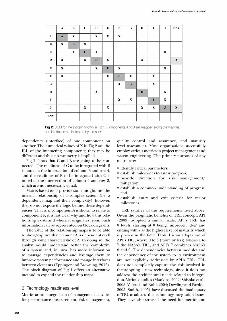
The block diagram of Fig 1 is mapped into design structure matrix (DSM) as shown in Fig 2. The DSM maps the elements of a system to each other (like a two-way table), enabling concise rep-resentation and integration analysis. One reads across a row of the matrix to see where the element in that row sends its outputs and reads down a col-umn to see from where the element in that column receives its inputs (Browning, 2001).
For example, the element E provides an output to elements A, D, F and J (reading across row 6) and receives an input from element A, D, F and J (reading down column 6). Hence a component location is known by its column and row. Informa-tion about dependency or interface is added by using a marker in the cells to represent relation-ships (x in Fig 2). An off-diagonal x signifies the
Fig 1: The block diagram for a system with two modules and 10 components (A to J). The double arrows indicate the interfaces between connected components
IRL=5
IRL=4
FTRL=5
ITRL=6
ETRL=5
GTRL=5
HTRL=5
JTRL=5
IRL=4
IRL=5
IRL=5
ENV=5
IRL=4
IRL=5
IRL=5
IRL=4
BTRL=5
DTRL=6
ATRL=6
CTRL=5
ENV=5 IRL=5 IRL=6
D to E IRL=5
C to J IRL=5
D to H IRL=6
A to F IRL=6
A to E IRL=5
Yasseri. Subsea system readiness level assessment
80
dependency (interface) of one component on another. The numerical values of X in Fig 2 are the IRL of the interacting components; they may be different and thus no symmetry is implied.
Fig 2 shows that C and B are going to be con-nected. The readiness of C to be integrated with B is noted at the intersection of column 3 and row 4, and the readiness of B to be integrated with C is noted at the intersection of column 4 and row 3, which are not necessarily equal.
Matrix-based tools provide some insight into the internal relationship of a complex system (i.e. a dependency map and their complexity); however, they do not expose the logic behind these depend-encies. That is, if component A is shown to relate to component F, it is not clear why and how this rela-tionship exists and where it originates from. Such information can be represented on block diagrams.
The value of the relationship maps is to be able to show/capture that element A is dependent on F through some characteristic of A. In doing so, the analyst would understand better the complexity of a system and, in turn, has more information to manage dependencies and leverage them to improve system performance and mange interfaces between elements (Eppinger and Browning, 2012). The block diagram of Fig 1 offers an alternative method to expand the relationship maps.
3. Technology readiness levelMetrics are an integral part of management activities for performance measurement, risk management,
quality control and assurance, and maturity level assessment. Most organisations successfully employ various metrics in project management and system engineering. The primary purposes of any metric are:
• identify critical parameters;•establish milestones to assess progress;•provide direction for risk management/
mitigation;•establish a common understanding of progress;
and•establish entry and exit criteria for major
milestones.
TRL satisfies all the requirements listed above. Given the pragmatic benefits of TRL concept, API (2009) adopted a similar scale. API’s TRL has 8 levels, starting at 0 being ‘unproven idea’ and ending with 7 as the highest level of maturity, which is proven in the field. Table 1 is an adaptation of API’s TRL, where 0 to 6 (more or less) follows 1 to 7 the NASA’s TRL, and API’s 7 combines NASA’s 8 and 9. The dependencies between modules and the dependency of the system to its environment are not explicitly addressed by API’s TRL. TRL does not completely capture the risk involved in the adopting a new technology, since it does not address the architectural needs related to integra-tion. Various studies (Mankins, 2002; Shishko et al., 2003; Valerdi and Kohl, 2004; Dowling and Pardoe, 2005; Smith, 2005) have discussed the inadequacy of TRL to address the technology integration issues. They have also stressed the need for metrics and
Fig 2: DSM for the system shown in Fig 1. Components A to J are mapped along the diagonal and interfaces are indicated by a maker
A B C D E F G H I J ENV
A A
B B
C C
D D
E E
F F
G G
H H
I I
J J
ENV

81
Vol 31, No 2, 2013
Table 1: TRL for subsea technology readiness level assessment (API, 2009)
Phase TRL Development stage Development stage definition
System validation 7 Field provenProduction system field proven
• Production unit integrated into intended operating system, installed and operating in the same environment and operating conditions for more than 10% of its design life with acceptable reliability, demonstrating low risk of early life failures.
6 System installedProduction system installed and tested
• Complies with all requirements of TRL 5.• Production unit or full-scale prototype built and integrated
into intended operating system.• Full interface and functional test programme performed
in intended or closely simulated environment and operated for less than three years.
• New technology equipment may require additional support for first 12 to 18 months of operation.
Technology validation 5 System testedProduction system interface tested
• Complies with all requirements of TRL 4.• Designed and built as production unit or full-scale
prototype and integrated into intended operating system with full interface and functional test, but not usually in intended field environment.
4 Environment testedPreproduction system environment tested
• Complies with all requirements of TRL 3.• Designed and built as a production unit or full-scale
prototype and put through qualification programme in simulated environment (e.g. hyperbaric chamber to simulate pressure) or actual intended environment (e.g. subsea environment) but not installed or operating.
• Reliability testing is limited to demonstrating that prototype function and performance criteria can be complied within the intended operating condition and external environment.
3 Prototype testedSystem function, performance and reliability tested
• Prototype built and put through generic functional and performance tests.
• Reliability tests are performed in relevant laboratory testing environment, including reliability growth tests, accelerated life tests and robust design development test programme.
• Tests are performed without integration into broader system.
• The extent of application compliance requirements are assessed and potential benefits and risks are demonstrated.
Concept validation 2 Validated conceptExperimental proof of concept using physical model tests
• Concept design or novel features of design validated by physical model, system mock-up or dummy, and functionally tested in laboratory environment.
• No design history. No environmental tests.• Materials testing and reliability testing performed on key
parts or components in testing laboratory prior to prototype construction.
1 Demonstrated conceptProof of concept as desk study or R&D experimentation
• No design history.• Essentially desk study not involving physical models but
may include R&D experimentation.• Technology concept and/or application formulated.• Concept and functionality proven by analysis
or reference to features common with/to existing technology.
0 Unproven conceptBasic research and development (R&D) in papers
• Basic scientific/engineering principles observed and reported in papers.
• No analysis or testing completed available.• No design history.

Yasseri. Subsea system readiness level assessment
82
methodology for the coupling and measuring the maturity of multiple technologies within systems.
4. Integration readiness levelIntegration is the process of assembling the system from its components (Buede, 2000). This seems to imply that ‘putting together’ a system from its com-ponents entails no complication, since components are built from specifications, which are recognisa-ble to any system engineer. However, integration can be a complex process containing multiple over-lapping and iterative tasks to create a delivery sys-tem, built to the user requirements and that will function in the marine environment.
The need for a reliable method becomes more imperative as a system’s complexity increases and components are sourced from diffident manufac-turers. Water depth and availability of installation vessel (the deck space for assembling components) and crane capacity could demand a specific inter-face type and hence add to complexity.
A technology can only be successfully inserted into a system if its functionality, maturity and com-patibility allow it to integrate with the rest of the system. The integration should not pose a problem if the technology and system evolve along similar maturation paths. However, the core technology components of a system receive more attention than the linkages between them. Inadequately conceived linkages can cause the integration of components from different suppliers to be problematic.
The application of metrics to support integration has been extensively used in the computer industry to define coupling of components (Orme et al., 2006; 2007). Mankins (2002) proposes an inte-grated technology analysis methodology to estimate an integrated technology index and used it for a comparative ranking of competing systems. Mankins highlights the difficulty of using the TRL index when choosing between alternatives.
The USDOD and MOD developed a technology insertion metric that includes an integration matu-rity level (Dowling and Pardoe, 2005). Gove et al. (2007) created an IRL to measure integration maturity on a scale similar to TRL.
An IRL metric should be able to:
•determine the integration maturity between two or more components and/or modules;
•provide a means to reduce the uncertainty in integrating new technology into a system;
•meet the system requirements in terms of deliv-ery time and functionality; and
•provide a common platform for tracking the system development and maturity assessment (Sauser et al., 2008a).
For a metric to be useful (Dowling and Pardoe, 2005), it must be:
•unambiguous; •understood by stakeholders with little effort; •adequately measure the integration maturity; •mirror the TRL for ease of implementation; and• simple to apply.
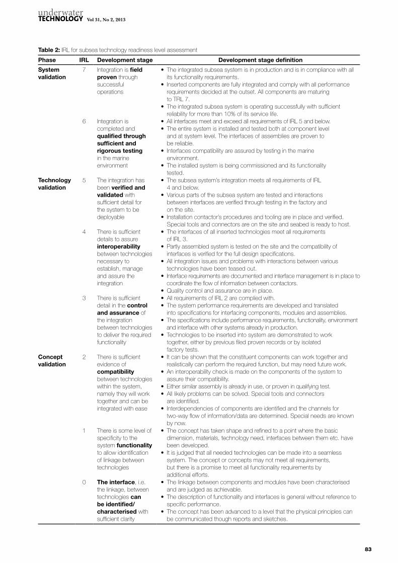
By drawing upon these studies, this paper extends the same concept to the subsea technology integration. Table 2 shows the proposed metric to measure the subsea IRL, which moves in parallel with TRL.
IRL, as TRL, consists of three stages: (1) concept validation; (2) technology validation; and (3) sys-tem validation (see Table 2). Concept validation is about deciding if a number of technologies can be brought together to perform a function. Clarity and differentiation are important factors at this stage. Thus IRL 0–2 are considered fundamental to describing the three principles of integration, namely interface, interaction and compatibility. The next stage is technology validation, which is defined as a conformance to rules. Thus IRLs 3–5 are about assurance that an integration solu-tion is in compliance with specifications. The final stage is system validation, which relates to practical considerations. IRLs 6 and 7 are about the assur-ance afforded by integration testing (in-place test-ing and actual performance in service).
There are also three aspects to the readiness measure: (1) readiness of components to be inte-grated into a module; (2) readiness of modules to be connected together to make an assembly; and (3) the readiness of the assembly to be integrated into the marine environment. Both components and modules are tested at the factory for compli-ance. The factory acceptance test (FAT) qualifies a module as ready to be transported to the site (i.e. IRL exceed 4). The assemblies of a few modules are leak-tested at the site to assure their interface read-iness for deployment. IRL must be 5 before it can be installed.
Now that both the technologies and integration elements can be assessed and mapped along a numerical scale, the next challenge is to develop a metric that aggregates TRL and IRL.
5. Systems readiness levelThe application of an IRL in the assessment proc-ess provides a check as to where the technology maturity is on an integration readiness scale. Just as a TRL has been used to assess the risk associated with developing technologies, an IRL is designed to assess the risk associated with integrating these
83
Vol 31, No 2, 2013
Table 2: IRL for subsea technology readiness level assessment
Phase IRL Development stage Development stage definition
System validation
7 Integration is field proven through successful operations
• The integrated subsea system is in production and is in compliance with all its functionality requirements.
• Inserted components are fully integrated and comply with all performance requirements decided at the outset. All components are maturing to TRL 7.
• The integrated subsea system is operating successfully with sufficient reliability for more than 10% of its service life.
6 Integration is completed and qualified through sufficient and rigorous testingin the marine environment
• All interfaces meet and exceed all requirements of IRL 5 and below.• The entire system is installed and tested both at component level
and at system level. The interfaces of assemblies are proven to be reliable.
• Interfaces compatibility are assured by testing in the marine environment.
• The installed system is being commissioned and its functionality tested.
Technology validation
5 The integration has been verified and validated with sufficient detail for the system to be deployable
• The subsea system’s integration meets all requirements of IRL 4 and below.
• Various parts of the subsea system are tested and interactions between interfaces are verified through testing in the factory and on the site.
• Installation contactor’s procedures and tooling are in place and verified. Special tools and connectors are on the site and seabed is ready to host.
4 There is sufficient details to assure interoperability between technologies necessary to establish, manage and assure the integration
• The interfaces of all inserted technologies meet all requirements of IRL 3.
• Partly assembled system is tested on the site and the compatibility of interfaces is verified for the full design specifications.
• All integration issues and problems with interactions between various technologies have been teased out.
• Interface requirements are documented and interface management is in place to coordinate the flow of information between contactors.
• Quality control and assurance are in place.3 There is sufficient
detail in the control and assurance of the integration between technologies to deliver the required functionality
• All requirements of IRL 2 are complied with.• The system performance requirements are developed and translated
into specifications for interfacing components, modules and assemblies.• The specifications include performance requirements, functionality, environment
and interface with other systems already in production.• Technologies to be inserted into system are demonstrated to work
together, either by previous filed proven records or by isolated factory tests.
Concept validation
2 There is sufficient evidence of compatibility between technologies within the system, namely they will work together and can be integrated with ease
• It can be shown that the constituent components can work together and realistically can perform the required function, but may need future work.
• An interoperability check is made on the components of the system to assure their compatibility.
• Either similar assembly is already in use, or proven in qualifying test.• All likely problems can be solved. Special tools and connectors
are identified.• Interdependencies of components are identified and the channels for
two-way flow of information/data are determined. Special needs are known by now.
1 There is some level of specificity to the system functionality to allow identification of linkage between technologies
• The concept has taken shape and refined to a point where the basic dimension, materials, technology need, interfaces between them etc. have been developed.
• It is judged that all needed technologies can be made into a seamless system. The concept or concepts may not meet all requirements, but there is a promise to meet all functionality requirements by additional efforts.
0 The interface, i.e. the linkage, between technologies can be identified/characterised with sufficient clarity
• The linkage between components and modules have been characterised and are judged as achievable.
• The description of functionality and interfaces is general without reference to specific performance.
• The concept has been advanced to a level that the physical principles can be communicated though reports and sketches.
Yasseri. Subsea system readiness level assessment
84
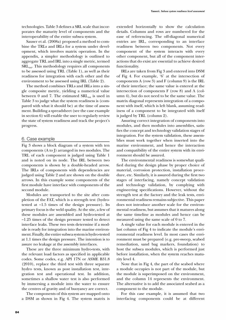
technologies. Table 3 defines a SRL scale that incor-porates the maturity level of components and the interoperability of the entire subsea system.
Sauser et al. (2008a) proposed a method to com-bine the TRLs and IRLs for a system under devel-opment, which involves matrix operation. In the appendix, a simpler methodology is outlined to aggregate TRL and IRL into a single metric, termed SRLest. This methodology requires all components to be assessed using TRL (Table 1), as well as their readiness for integration with each other and the environment to be assessed using IRL (Table 2).
The method combines TRLs and IRLs into a sin-gle composite metric, yielding a numerical value between 0 and 7. The estimated SRLest is used in Table 3 to judge what the system readiness is (com-pared with what it should be) at the time of assess-ment. Building a spreadsheet (see the case example in section 6) will enable the user to regularly review the state of system readiness and track the project’s progress.
6. Case exampleFig 3 shows a block diagram of a system with ten components (A to J) arranged in two modules. The TRL of each component is judged using Table 1 and is noted on its node. The IRL between two components is shown by a double-headed arrow. The IRLs of components with dependencies are judged using Table 2 and are shown on the double arrows. In this example some components of the first module have interface with components of the second module.
Modules are transported to the site after com-pletion of the FAT, which is a strength test (hydro-tested at ~1.5 times of the design pressure). Its primary focus is the weld quality. At the site, a few of these modules are assembled and hydro-tested at ~1.25 times of the design pressure tested to detect interface leaks. These two tests determine if a mod-ule is ready for integration into the marine environ-ment. Finally, the entire subsea system is hydro-tested at 1.1 times the design pressure. The intention is to assure no leakage at the assembly interfaces.
These are the three minimum hydro-tests, with the relevant load factors as specified in applicable codes. Some codes, e.g. API 17N or ASME B31.8 (2010), replace the third test with three separate hydro tests, known as post installation test, inte-gration test and operational test. In addition, sometimes a shallow water test is also performed by immersing a module into the water to ensure the centres of gravity and of buoyancy are correct.
The components of this system are mapped onto a DSM as shown in Fig 4. The system matrix is
extended horizontally to show the calculation details. Columns and rows are numbered for the ease of referencing. The off-diagonal numerical entries are IRL, corresponding to an interface readiness between two components. Not every component of the system interacts with every other component, but all of the component inter-actions that do exist are essential to achieve desired functionality.
IRLs are taken from Fig 3 and entered into DSM of Fig 4. For example, ‘6’ at the intersection of components A (row 3) and F (column 9) is the IRL of their interface; the same value is entered at the intersection of components F (row 8) and A (col-umn 4), but do not need to be the same value. The matrix diagonal represents integration of a compo-nent with itself, which is left blank, assuming read-iness of a component to be integrated with itself is judged by TRL (column 2).
Assuring correct integration of components into modules, and then modules into assemblies, satis-fies the concept and technology validation stages of integration. For the system validation, these assem-blies must work together when inserted into the marine environment, and hence the interaction and compatibility of the entire system with its envi-ronment should be assured.
The environmental readiness is somewhat quali-fied during the design phase by proper choice of material, corrosion protection, installation proce-dure, etc. Similarly, it is assured during the first two stages of interfacing, namely concept validation and technology validation, by complying with engineering specifications. However, without the strength test at the factory and the leak tests, envi-ronmental readiness remains subjective. This paper does not introduce another scale for the environ-mental readiness, but assumes that it matures along the same timeline as modules and hence can be measured using the same scale of 0 to 7.
A single value for each module is entered in the last column of Fig 4 to indicate the module’s envi-ronmental readiness level. In most cases the envi-ronment must be prepared (e.g. pre-sweep, seabed remediation, sand bag markers, foundation) to host the subsea modules, which is performed just before installation, when the system reaches matu-rity level 4.
Note that in Fig 4, the part of the seabed where a module occupies is not part of the module, but the module is superimposed on the environment, and the column 14 represents the environment. The alternative is to add the associated seabed as a component to the module.
For this case example, it is assumed that two interfacing components could be at different

85
Vol 31, No 2, 2013
Table 3: SRL for subsea system readiness level assessment
Phase SRL Development stage Development stage definition
System validation 7 Field proven operational system
• The subsea system is in production and it is in compliance with all its functionality requirements.
• The subsea system is operating successfully with sufficient reliability for more than 10% of its service life.
• Assure the operation support will meet all of its expected functions.
6 The system is installed tested and commissioning in progress
• The entire subsea system is installed and tested both at component level and at the system level, and it is ready for its intended operation condition.
• The subsea system is being commissioned with operation support.
• Any remaining problems being rectified.• The Health and Safety Executive (HSE) policy is monitored.
Technology validation 5 Manufacturing and installation in progress
• The system with all inserted assemblies will meet all requirements of SRL4 and below.
• Partly assembled/installed system is tested and compliance verified for the full design specifications.
• Operational support availability is identified and assured.• HSE, pre-commissioning and handover policy are established.• Operation support needs are established.
4 Detail design and final procurement
• The chosen concept is detailed.• Procurement date for long lead items is assured.• Installation and commissioning contactors are ready.• Integration and manufacturing risk are reduced.• Procurement is advanced.• Seabed is being prepared to host the system.
3 Front end engineering, sourcing long lead items
• The first choice and the competing option are moved forward to a level that the difference between them becomes obvious.
• Vendors, installation and commissioning contactors are selected and appointed, and assurance that they can meet the delivery dates is made.
• Possible integration problems are checked.• Logistics are considered.• The concept is in compliance with the demands by the
marine environment.• Seabed is being surveyed.
Concept validation 2 Concept selection,where an optimal concept has emerged
• Two or more options which best satisfy all requirements are identified.
• Technology risk is reduced.• Aspect of technologies to be used is clarified.• The most promising option is selected.• The project schedule is determined.
1 Concept refinementTwo or more competing concept being considered
• Promising concept is refined to an adequate level of maturity.• The concepts are priced and ranked according to
their desirability.• Technologies that are needed are researched to see if they can
be procured and at what price.• The available infrastructure, means of transportation and
installation contactors availability are studied.• Operational requirements are considered.• Fabrication, transportation and installation are considered.• The influence of the marine environment on the system is
studied and written into the basis of design.0 Concept definition,
where various ideas are being considered or discounted
• Reservoir data, geotechnical data, drilling requirements, distances and existing infrastructure information is collected.
• Concepts are developed.• Economically or technically unfeasible concepts are
screened out.• The schedules are established and checked if they
are realistic.• Finance is considered.

Yasseri. Subsea system readiness level assessment
86
TRL, but their IRLs are the same and equal to the less ready component (because of mutual depend-ency), hence yielding a symmetric matrix. In gen-eral, if two components have to come together to create a connection, there may be different degrees of integration readiness for each component and therefore the matrix is not symmetric. Symmetry assumption is not necessary for the success of the method and can be dropped, if it is believed that retaining two different IRL for interfacing components would yield useful information.
The distance between the furthest off-diagonal terms to the diagonal is known as the bandwidth of the matrix. A narrow bandwidth is an indication of a good system line-up (modularisation). A high bandwidth, as in this example, signifies that too many components from different modules are
dependent on each other, which adds to the cost of managing the interface and will probably lead to delays. There are algorithms to collect components into modules in order to reduce the bandwidth and lower the dependencies.
Each row of column 15 of Fig 4 is the average IRL for the row, determined by summing up of IRLs of all interfaces across the row and dividing it by the number of interfaces – e.g. (5 + 6 + 5 + 6)/4 = 5.5. Column 16 gives the results of multiplication of the component’s TRL by the average of its IRLs, e.g. in row 3, it is 6 × 5.5 = 33. The square root of column 16 is given in column 17, giving a composite compo-nent readiness index. Column 18 is the square root of mean of squares noted in column 16, which is the sum of all squares in column 16 divided by the number of components in the module.
Fig 3: A simple system consisting of 10 components arranged in two modules. Interfaces are shown by double headed arrow
PreviousModule
IRL=5
IRL=5
FTRL=5
ITRL=6
ETRL=5
GTRL=5
HTRL=5
JTRL=5
IRL=5
IRL=5
IRL=4
IRL=4
IRL=4
ENV=5
ENV=5IRL=6 IRL=5
NextModule
IRL=5
IRL=4
BTRL=5
DTRL=6
ATRL=6
CTRL=5
A to E IRL=5
D to H IRL=6
C to J IRL=5
D to E IRL=5
A to F IRL=6

87
Vol 31, No 2, 2013
The readiness for the first module is calculated as:
33 25.00 23.33 31.504
5.311M R =+ + +
= (1)
The denominator of 4 is the number of compo-nents of the first module. Similarly for the second module, the readiness is calculated as:
25.00 25.00 22.50 25.00 26.0 23.756
4.95
2M R =+ + + + +
=
Therefore, the readiness of each module to be integrated into its environment is judged to be 5 for both modules of the case example using Table 3. Hence, the aggregate system readiness index (SRI) is:
=
× + ××
=(5.31) 5 (4.95) 5
7 24.34
2 2
SRI (3)
The denominator of 7 is the highest IRL in Table 2; this number is used to normalise the environmen-tal integration readiness level, namely 5/7, which is the same for both modules in the example. From a metric point of view, SRLest and SRL are meant to measure the same things on the same scale. How-ever, SRL is defined (Table 3), while SRLest is derived by aggregation of attributes of all components, which may be at different levels of TRL and IRL. If all components mature simultaneously along the same path, then SRLest reduces to SRL.
Entering Table 3 with 4.34, the system must be at assembly and installation stage; if the project sched-ule requires a different level then this must be justi-fied. This index informs the management when and where to intervene if the system readiness is lag-ging behind the schedules. The markers in each row identify which other components must be ready for the integration to become complete; hence interfaces must be adequately managed. A tightly
controlled project ensures that TRL, IRL and SRL closely follow each other. The derived system readi-ness index of 4.34 indicates that some components are not maturing within the desired time frame. In this hypothetical example, components with TRL or IRL lower than 4.34 need to be scrutinised.
While this case example is simple, the underlying methodology is important. It demonstrates how to use DSM to combine TRL and IRL into a new met-ric, which indicates the readiness of the system. In addition to this housekeeping advantage, DSM pro-vides a visual aid to present the system audit results to the senior managers. The advantage becomes more evident when dealing with more than 200 components manufactures in various locations that must mate and work together when assembled.
7. DiscussionMeasuring technology and system maturity is a multidimensional process that cannot be per-formed adequately by a one-dimensional metric such as TRL. Although TRL has been employed by many industries, it captures only a part of the infor-mation needed to support stakeholders’ decisions. TRL was not designed to assess the quality of the system architecture, design or integration, but only to measure the readiness of system components based on what has been accomplished at the time of assessment.
IRL addresses this shortcoming, but it must be aggregated with TRL into a single composite index to be useful. In turn, there is a need for a scale to be used with this composite index. It is also proposed to use DSM as a visual aid to bring together all three elements of system maturation metrics. Readiness of components to be integrated into a module, or modules to be connected together, may be assessed by engineering judgment in formal reviews, assisted by measurements, specifications, codes and procedures.
(2)
Fig 4: DSM for the example case
1 2 3 4 5 6 7 8 9 10 11 12 13 14 15 16 17 18
2 TRL A B C D E F G H I J ENVAve.IRL
TRL*Ave_IRL
SQRT(Col16)
3 6 A 5 6 5 6 5.50 33.00 5.74
5.314 5 B 5 5 5.00 25.00 5.005 5 C 5 4 5 4.67 23.33 4.836 6 D 6 4 5 6 5 5.25 31.50 5.61
7 5 E 5 5 5 5 5.00 25.00 5.00
4.95
8 5 F 6 5 5 4 5.00 25.00 5.009 5 G 5 4 4.50 22.50 4.74
10 5 H 6 4 5.00 25.00 5.0011 6 I 4 4 5 4.33 26.00 5.1012 5 J 5 5 4 5 5 4.75 23.75 4.87
13 4.34

Yasseri. Subsea system readiness level assessment
88
This paper has also introduced the concept of envi-ronmental integration readiness level (i.e. module/ assemblies-to-marine-environment) for assemblies consisting of several modules that are large/heavy enough to be installed in a single operation. The readiness of all components cannot be assured until the factory acceptance tests, the leak tests at the site and in-place operational tests are per-formed. It should be kept in mind that by IRL = 5, all of the technical integration issues must be resolved. Once it reaches this level, the focus should be on confirmations of integration by more testing and the actual performance. In the context of this work, the integration readiness of modules-to-marine-environment may be judged using the avail-able physical evidences, e.g. tests and compliance with rules, specifications and codes.
The root mean square (RMS) method was used for determining SRLest (see for example Bissell and Chapman, 1992). This estimated value incor-porates not only the current maturation of all components, but also the physical properties of interfaces, integrations requirements, interaction, compatibility, reliability, quality and performance when assemblies are brought together to deliver a specific functionality.
The dependency of the system on the seabed is generally studied at the concept phase, and the demand of environment, such as geohazards, cor-rosion, unstable and uneven seabed are identified and written into the basis of design (BOD). The compliance of the design with the BOD is reviewed at all stages of the system development. Thus, the manufactured modules are expected to withstand the demand of its environment when installed. However, the readiness of environment to host the system is considered when the subsea system is ready to be installed.
Early seabed surveys help to identify suitable positions for the subsea system. However, the major part of making the seabed ready for receiving the subsea system takes place before installation, when the modules and assemblies readiness exceed level 4. The major activities for the installation preparation are:
•acquisition of the permit (permission) for the vessel to enter the area;
•deployment of ship’s transponder on the seabed;
•deepwater trials to assure redundancy of the deepwater system and also drift off tests;
•as-found survey looking for anomalies, debris and variation of the seabed;
• installation of transponders array to obtain a frame of reference for poisoning;
• seabed corrections and remediation, involving removal of debris, possibly dredging and shoring up; and
•accurate positioning/laying down buoyancy markers ballasted with sand bags. These mark-ers act as visual aids for installation, by for example, identifying the corner locations for structures.
The linear asset (e.g. pipelines, flowlines) fol-lows a similar path, but is not necessarily in sync with the major equipment. Some post installa-tion interventions, e.g. trenching of pipelines and piling of subsea structures, may be required to secure the asset.
The subsea architecture is represented by a component-component (N-square) matrix – the DSM – which can describe a system structure with respect to the relationships between its compo-nents. The DSM is an effective representation tool for mapping subsea equipment and its linkages. DSM provides a platform for communicating about quality and alternative architecture, and managing interfaces. Its use can improve understanding of the project progress and communicating this to the senior managers. Simply building the DSM helps to increase overall awareness and understanding the relationship between components in the system. Integration analysis using a DSM promotes trans-parency by showing all metrics in one picture.
DSMs can also address the following types of questions:
•Should the components be organised differently to improve interface management and delivery?
•How should those modules requiring too many interfaces be reconfigured?
•Where and which integrative mechanisms might be prudent?
•Are the current choices of integrative mecha-nisms well balanced?
•Are the interactions as shown in DSM correct and sufficient for the interface management?
Interfaces between components of one module do not require the same level of management time as interfaces between components of two or more modules supplied by different vendors. The goal of DSM is to analyse the components within a system, and it allows one to re-sequence these in order to minimise interface between modules.
DSM identifies bottlenecks during design, fabri-cation and installation. The diagonal entries of the matrix do not have any interpretation in describing the system; they are either left blank, or filled in with the component labels. This is done to separate the upper and lower triangles of the matrix and to
89
Vol 31, No 2, 2013
show the interfaces more clearly. The number of markers in a row determines dependencies, as well as the level of demand on the interface manage-ment and the criticality of the component. DSM can become the foundation for the optimal resource allocation, monitoring and evaluation tool. It can also be a basis for common measure-ment and language for delivery managers to improve the system development and acquisition process.
The complexity of the interfaces is not shown on the Fig 4, but it can be indicated by colour coding of the relevant cell using a five level designation: none, minor, moderate, high and very high. No colour implies that there is no specific interface requirement or, if there is one, that its complexity is negligible. An alternative is to use a scale of 1 to 5 with 5 being the highest.
The methodology that is described here is simple enough to be usable in practice, and yet adequately captures all relevant data and gives a clear picture of the entire system. It provides, with little effort from the user, a view of the system that is valuable especially during ongoing development. The con-cepts described here complement the practice of TRL and offers a vision of the system readiness that is compatible with the intuition of practicing engineers.
8. Concluding remarksThis paper presents a system-based approach for managing subsea system development and mak-ing effective and efficient decisions for hardware and software, acquisition and their integration. This provides system engineers, delivery managers, quality control managers and project managers a common metric that can aid them in making effec-tive and timely decisions during all phases of a sub-sea system development. This should help reduce both a project’s technical risk and schedule risk.
The new IRL scale, which parallels the current TRL scale, is necessary because when components are procured from different sources, integration could pose a problem if not properly managed. The proposed IRL mimics the value of the TRL by being simple to understand and use. A new SRL is also introduced as a scale for measuring the matu-ration of the entire subsea system. To tie up these three matrices, a methodology is described that combines TRLs and IRLs at the time of evaluation, into a single composite index termed SRLest. This composite index is an estimate of the system readiness level. By applying Table 3 and this index, the stage of advancement of the project can be determined.
This paper also introduces the DSM for map-ping the subsea architecture, namely all compo-nents and their linkages, into a single table (matrix) as a visual aid. DSM shows interdependencies between components and the need for information flow for the interface management. Consequently, DSM shows TRL and IRL in a single table. These metrics can identify critical parameters, establish milestones to assess progress, offer direction for risk management/mitigation and identify hot spots requiring management intervention.
In summary, this paper provides a basis for:
•collective evaluation of component integration and system readiness to reduce schedule and technical risks;
•a dynamic assessment tool for tracking the progress of design, manufacturing and installa-tion; and
•developing contingency, multiple-sourcing and sparing policy through the comparative analysis of multiple technologies.
ReferencesAmerican Petroleum Institute (API). (2009). AP RP 17N
Recommended practice for subsea production system reliability and technical risk management. Washington DC: API.
Bilbro JW. (2007). A suite of tools for technology assess-ment. Presented at: Technology maturity conference: multi-dimensional assessment of technology maturity. Virginia Beach, VA, 11–13 September. Available at www.dtic.mil/cgi-bin/GetTRDoc?AD=ADA507181 last accessed <10 October 2012>.
Bissell C and Chapman D. (1992). Digital Signal Transmis-sion. Cambridge University Press. UK.
Browning TR. (2001). Applying the Design Structure Matrix to System Decomposition and Integration Problems: A Review and New Directions. IEEE Transactions on Engi-neering Management 48: 292–306.
Browning TR and Eppinger S. (2002). Modelling Impacts of Process Architecture on Cost and Schedule Risk in Product Development. IEEE Transactions on Engineering Management 49: 428–442.
Buede DM. (2000). The engineering design of systems: Models and methods. New York: Wiley.
Bureau Veritas (BV). (2010). BV NI525:2010 Risk based qualification of new technology methodological guide-lines. Neuilly-sur-Seine, France: BV, 20pp.
Danilovic M and Browning RT. (2007). Managing complex product development projects with design structure matrices and domain mapping matrices. International Journal of Project Management 25: 300–314.
Det Norske Veritas (DNV). (2011). DNV-RP-A203 Recom-mended practice: Qualification of new technology. Oslo, Norway.
Dowling T and Pardoe T. (2005). TIMPA – Technology insertion metrics, volume 1. London: Ministry of Defence, QinetiQ.
Eppinger SD. (1991). Model-based approaches to manag-ing concurrent engineering. Journal of Engineering Design 2: 283–290.

Yasseri. Subsea system readiness level assessment
90
Eppinger SD and Browning TR. (2012). Design structure matrix methods and applications (engineering systems). Cambridge, MA: MIT Press, 280pp.
Gove R, Sauser B and Ramirez-Marquez J. (2007). Integra-tion maturity metrics: development of an integration readiness level. Hoboken, NJ: Stevens Institute of Technology, School of Systems and Enterprises.
Mankins JC. (2002). Approaches to strategic research and technology (r&t) analysis and road mapping. Acta Astro-nautica 51: 3–21.
Millheim K, Williams TE and Yemington CR. (2011). Evalu-ation of well testing systems for three deepwater gulf of mexico (GOM) reservoir types, SPE 145682. Richardson, TX: Soci-ety of Petroleum Engineers.
Mineral Management Service (MMS). (2010). US MMS – Enhance Recovery Study, Document and Revision Number: KRNACRI090620-020FR, total number of pages 81.
Ministry of Defence (MOD). (2008). System Readiness Levels (SRLs). AOF Technology Management Policy, Information and Guidance on the Technology Manage-ment aspects of Defence Acquisition version 1.0.1. London: MOD.
MOD. (2011). Defence Technology Strategy for the Demands of the 21st Century. London: MOD.
Orme AM, Yao H and Etzkorn LH. (2006). Coupling Metrics for Ontology-Based Systems. IEEE Software 23: 102–108.
Orme AM, Yao H and Etzkorn LH. (2007). Indicating ontology data quality, stability, and completeness throughout ontology evolution. Journal of Software Main-tenance and Evolution 19: 49–75.
Sauser BJ, Ramirez-Marquez JE, Henry D and DiMarzio D. (2008a). A system maturity index for the systems engi-neering life cycle. International Journal of Industrial and Systems Engineering 3: 673–691.
Sauser B, Ramirez-Marquez JE, Magnaye R and Tan W. (2008b). A systems approach to expanding the technol-ogy readiness level within defense acquisition. Interna-tional Journal of Defense Acquisition Management 1: 39–58.
Sharman D and Yassine AA. (2004). Characterizing Complex Product Architectures. Systems engineering 7: 35–60. DOI: 10.1002/sys.10056.
Shishko R, Ebbeler DH and Fox G. (2003). NASA Technol-ogy Assessment Using Real Options Valuation. Systems Engineering 7: 1–12.
Simon HA. (1962). The architecture of complexity. Proceed-ings of the American Philosophical Society 106: 467–482.
Smith JD. (2005). An alternative to technology readiness levels for non-developmental item (NDI) software. Paper read at 38th Hawaii International Conference on System Sciences.
Steward DV. (1981). The design structure system: a method for managing the design of complex systems. IEEE Trans-actions on Engineering Management 28: 71–74.
US Department of Defense (USDOD). (1998). Levels of Information Systems Interoperability, the US Depart-ment of Defense. Available at www.eng.auburn.edu/ ~hamilton/security/DODAF/LISI.pdf last accessed <13 January 2013>.
USDOD. (2008). DOD Directive 5000.2 – Instruction: Operation of the Defence Acquisition System: US Department of Defense. Available at www.dtic.mil/whs/directives/corres/pdf/500002p.pdf last accessed <13 January 2013>.
USDOD. (2009). Technology Readiness Assessment (TRA) Desk-book, Research Directorate, Office of the Director, Defence Research and Engineering (DDR&E), US Depart-ment of Defence. Available at www.acq.osd.mil/ddre/publications/docs/TRA2011.pdf last accessed <13 January 2013>.
Valerdi R and Kohl RJ. (2004). An approach to technology risk management. Paper read at engineering systems division symposium, 29–31 March, Cambridge, MA. Available at http://web.mit.edu/rvalerdi/www/TRL%20paper%20ESD%20Valerdi%20Kohl.pdf last accessed <13 January 2013>.
Yassine A and Braha D. (2003). Complex Concurrent Engi-neering and the Design Structure Matrix Method. Vol-ume 11 Number 3. Concurrent Engineering: Research and Applications. Sage Publications.
Yassine A, Whitney D, Daleiden S and Lavine J. (2003). Con-nectivity maps: modelling and analysing relationships in product development processes. Journal of Engineering Design 14: 377–394.
91
Vol 31, No 2, 2013
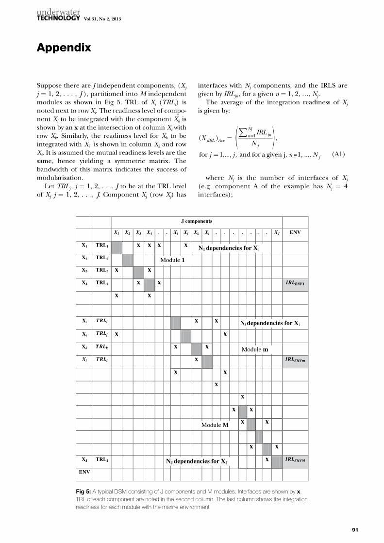
Suppose there are J independent components, (Xj j = 1, 2, . . . , J ), partitioned into M independent modules as shown in Fig 5. TRL of Xi (TRLi) is noted next to row Xi. The readiness level of compo-nent Xi to be integrated with the component Xk is shown by an x at the intersection of column Xi with row Xk. Similarly, the readiness level for Xk to be integrated with Xi is shown in column Xk and row Xi. It is assumed the mutual readiness levels are the same, hence yielding a symmetric matrix. The bandwidth of this matrix indicates the success of modularisation.
Let TRLj , j = 1, 2, . . ., J to be at the TRL level of Xj j = 1, 2, . . ., J. Component Xj (row Xj) has
interfaces with Nj components, and the IRLS are given by IRLjn , for a given n = 1, 2, …, Nj .
The average of the integration readiness of Xj is given by:
( ) ,
for 1,..., , and for a given j, =1, ...,
1XIRL
N
j j n N
jIRL Avejnn
Nj
j
j
∑=
=
=
where Nj is the number of interfaces of Xj
(e.g. component A of the example has Nj = 4 interfaces);
(A1)
Fig 5: A typical DSM consisting of J components and M modules. Interfaces are shown by x. TRL of each component are noted in the second column. The last column shows the integration readiness for each module with the marine environment
J components
X1 X2 X3 X4 . . Xi Xj Xk Xl . . . . . . . XJ ENV
X1 TRL1
X2 TRL2
X3 TRL3
X4 TRL4
Xi
Xj
Xk
Xl
XJ TRLJ
ENV
N1 dependencies for X1
Module 1
Module m
Module M
NJ dependencies for XJ
Ni dependencies for X i
Appendix
Yasseri. Subsea system readiness level assessment
92
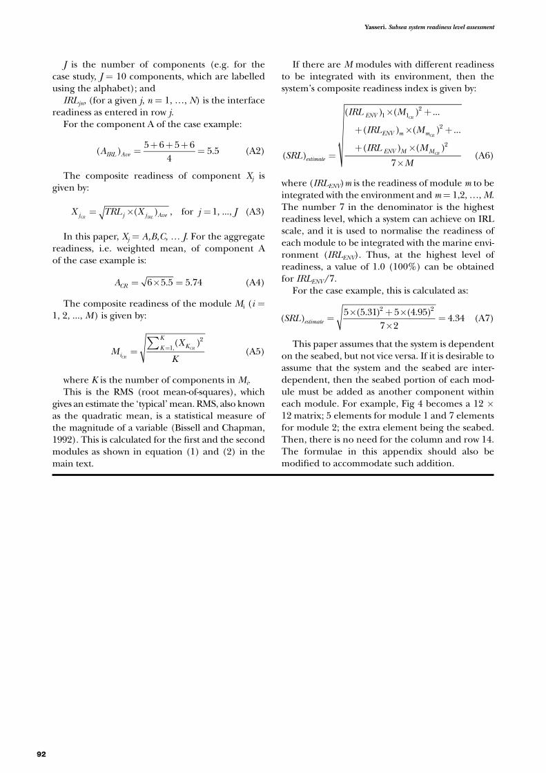
J is the number of components (e.g. for the case study, J = 10 components, which are labelled using the alphabet); and
IRLjn, (for a given j, n = 1, …, N) is the interface readiness as entered in row j.
For the component A of the case example:
=
+ + +=( )
5 6 5 64
5.5AIRL Ave (A2)
The composite readiness of component Xj is given by:
( ) , for 1, ...,X TRL X j Jj j j AveCR IRL
= × = (A3)
In this paper, Xj = A,B,C, … J. For the aggregate readiness, i.e. weighted mean, of component A of the case example is:
= × =6 5.5 5.74ACR (A4)
The composite readiness of the module Mi (i = 1, 2, ..., M) is given by:
∑= =
( )21,M
X
KiKK
K
CR
CR (A5)
where K is the number of components in Mi.This is the RMS (root mean-of-squares), which
gives an estimate the ‘typical’ mean. RMS, also known as the quadratic mean, is a statistical measure of the magnitude of a variable (Bissell and Chapman, 1992). This is calculated for the first and the second modules as shown in equation (1) and (2) in the main text.
If there are M modules with different readiness to be integrated with its environment, then the system’s composite readiness index is given by:
=
× +
+ × +
+ ×
×( )
( ) ( ) ...
( ) ( ) ...
( ) ( )
7
1 12
2
2
SRL
IRL M
IRL M
IRL M
Mestimate
ENV
ENV m m
ENV M M
CR
CR
CR (A6)
where (IRLENV)m is the readiness of module m to be integrated with the environment and m = 1,2, …, M. The number 7 in the denominator is the highest readiness level, which a system can achieve on IRL scale, and it is used to normalise the readiness of each module to be integrated with the marine envi-ronment (IRLENV). Thus, at the highest level of readiness, a value of 1.0 (100%) can be obtained for IRLENV / 7.
For the case example, this is calculated as:
( )5 (5.31) 5 (4.95)
7 24.34
2 2
SRL estimate =× + ×
×= (A7)
This paper assumes that the system is dependent on the seabed, but not vice versa. If it is desirable to assume that the system and the seabed are inter-dependent, then the seabed portion of each mod-ule must be added as another component within each module. For example, Fig 4 becomes a 12 × 12 matrix; 5 elements for module 1 and 7 elements for module 2; the extra element being the seabed. Then, there is no need for the column and row 14. The formulae in this appendix should also be modified to accommodate such addition.