understanding porosity formation and prevention …
TRANSCRIPT

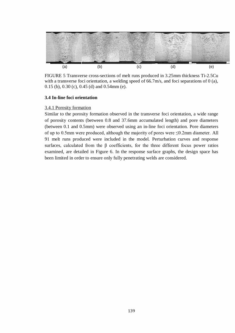
1
UNDERSTANDING POROSITY FORMATION AND PREVENTION
WHEN WELDING TITANIUM ALLOYS WITH 1 microm
WAVELENGTH LASER BEAMS
A thesis submitted to The University of Manchester for the degree of
Doctor of Engineering
in the Faculty of Engineering and Physical Sciences
2011
JONATHAN EDWARD BLACKBURN
SCHOOL OF MECHANICAL AERSOSPACE AND CIVIL ENGINEERING
2
List of Contents
LIST OF CONTENTS 2
LIST OF TABLES 7
LIST OF FIGURES 9
LIST OF SYMBOLS 13
LIST OF ABBREVIATIONS 16
ABSTRACT 18
DECLARATION 19
COPYRIGHT STATEMENT 20
ACKNOWLEDGEMENTS 21
PUBLICATIONS 22
PREFACE 23
CHAPTER 1 INTRODUCTION 24
11 GROWTH OF THE LASER MATERIALS PROCESSING INDUSTRY 24
12 TITANIUM USAGE IN AEROSPACE APPLICATIONS 25
13 KEYHOLE LASER WELDING 25
14 AIM AND OBJECTIVES 27
15 THE ENGINEERING DOCTORATE DEGREE 28
151 The Research Project 28
152 The Taught Element 28
153 Professional Development 29
16 THESIS STRUCTURE 29
PART I LITERATURE REVIEW 31
CHAPTER 2 LITERATURE REVIEW PART I AN OVERVIEW OF LASER WELDING
TITANIUM ALLOYS FOR AEROSPACE APPLICATIONS 32
List of Contents
3
21 INTRODUCTION 32
22 LASER LIGHT AND ITS INTERACTION WITH METALLIC MATERIALS 33
221 Key Characteristics of Laser Light 33
222 Absorption by the Solid Phase 36
223 Conduction and Melting 38
224 Vaporisation 39
225 Plasma Formation 40
23 LASER WELDING FUNDAMENTALS 41
231 Conduction Limited Laser Welding 41
232 Keyhole Laser Welding 43
24 LASER WELDABILITY OF TITANIUM ALLOYS 46
241 Embrittlement 48
242 Cracking 49
243 Geometrical Weld Profile Defects 49
244 Weld Metal Porosity 51
2441 Hydrogen Porosity 52
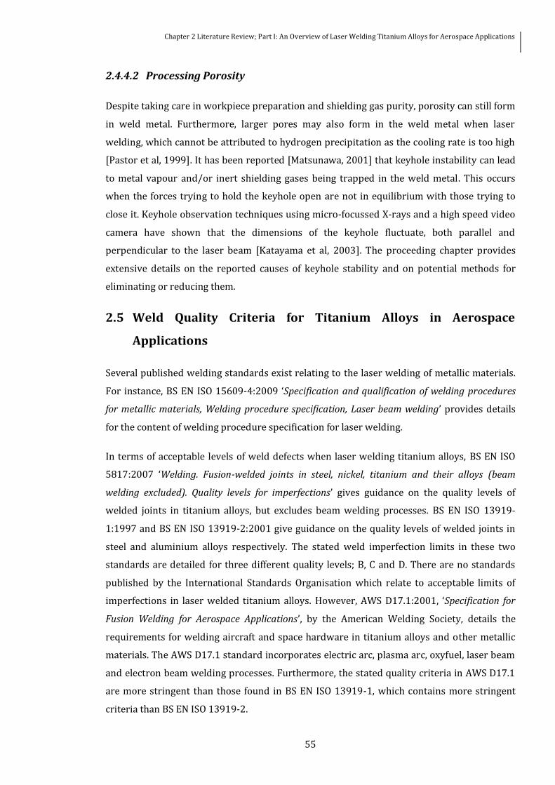
2442 Processing Porosity 55
25 WELD QUALITY CRITERIA FOR TITANIUM ALLOYS IN AEROSPACE APPLICATIONS 55
2511 AWS D171 2001 56
2512 Company Specific Standards 58
26 ADVANCES IN SOLID-STATE LASER TECHNOLOGY 59
27 SUMMARY 62
CHAPTER 3 LITERATURE REVIEW PART II KEYHOLE BEHAVIOUR AND THE
FORMATION AND PREVENTION OF POROSITY 63
31 INTRODUCTION 63
32 KEYHOLE BEHAVIOUR - LOW PEacuteCLET NUMBER 64
33 KEYHOLE BEHAVIOUR - HIGH PEacuteCLET NUMBER 67
331 Keyhole Geometry 67
332 Absorption Mechanism(s) 68
3321 Fresnel Absorption 69
3322 Inverse Bremsstrahlung Absorption 70
3323 Absorption of 1 and 10 microm Wavelength Laser Beams 72
333 Melt pool Behaviour and Hydrodynamic Forces 75
3331 Keyhole Ablation Pressure Effects 78
3332 Metallic Vapour Ejection Effects 79
List of Contents
4
3333 Marangoni Convection Effects 80
34 ORIGINS OF WELD METAL POROSITY 81
341 Pore Gas Analysis 81
342 Transient Behaviour of the Keyhole Laser Welding Process 82
35 PLASMA AND PLUME ATTENUATION EFFECTS 85
351 Introduction 85
352 Plasma Attenuation Mechanisms 86
353 Plume Attenuation Mechanisms 89
354 Laser Beam Brightness Effects 90
36 POTENTIAL POROSITY PREVENTION METHODS 93
361 Shielding Atmosphere 94
362 Directed Gas Jet 95
363 Dual Focus Keyhole Laser Welding 98
364 Modulated Keyhole Laser Welding 99
365 Magnetic Fields 100
37 SUMMARY PROJECT AIM AND PROJECT OBJECTIVES 101
PART II TECHNICAL ASPECTS 104
CHAPTER 4 RESEARCH METHODOLOGY 105
41 INTRODUCTION 105
42 RESEARCH APPROACH 106
43 MATERIALS 107
431 Titanium Sheets 107
432 Material Preparation 108
433 Filler Material 108
44 LASER PROCESSING EQUIPMENT 109
441 NdYAG Laser Sources 109
442 Yb-fibre Laser Sources 110
45 PROCEDURES 111
451 Beam Waist Position and Power Measurements 111
452 Test Piece Clamping 112
453 Shielding Gas 113
454 Directed Gas Jet Positioning 114
455 Modulated Waveform Programming 115
456 Dual Focus Configurations 115
457 Wire Feed 116
List of Contents
5
46 HIGH SPEED VIDEO OBSERVATIONS 116
461 High Speed Cameras 117
462 Illumination Laser Sources 118
463 Post Processing 119
464 Optical Spectroscopy 120
465 Particle Sampling 122
47 WELD QUALITY EVALUATION 122
471 Discoloration 122
472 Weld Metal Porosity 123
473 Profile 124
48 PORE CHARACTERISATION 124
49 SCOPE OF WORK 124
CHAPTER 5 NDYAG LASER WELDING WITH A DIRECTED GAS JET 128
51 INTRODUCTION 128
CHAPTER 6 MODULATED NDYAG LASER WELDING 129
61 INTRODUCTION 129
CHAPTER 7 DUAL FOCUS NDYAG LASER WELDING 130
71 INTRODUCTION 130
CHAPTER 8 WELDING WITH EXCELLENT BEAM QUALITY 1 microM WAVELENGTH LASER
SOURCES 148
81 INTRODUCTION 148
CHAPTER 9 POROSITY FORMATION 166
91 INTRODUCTION 166
92 POROSITY FORMATION MECHANISMS 166
93 PORE GAS ANALYSIS 168
931 Vacuum Hot Extraction 168
932 Mass Spectroscopy 169
94 SCANNING ELECTRON MICROSCOPY 169
95 BUBBLE RISE TIME 171
96 ORIGIN OF PORE GASES 173
PART III COMMERCIAL ASPECTS 175
CHAPTER 10 THE SPONSORING COMPANY - TWI 176
List of Contents
6
101 INTRODUCTION 176
102 HISTORY AND OVERVIEW 176
103 CORE BUSINESS AND KEY MARKETS 178
1031 Technology Readiness Levels 179
1032 Research and Development Project Types 180
104 ORGANISATIONAL STRUCTURE 182
105 COMMUNICATION CHANNELS 185
106 TECHNOLOGY INNOVATION186
107 THIS PROJECT 188
CHAPTER 11 COMMERCIAL IMPLICATIONS 190
111 INTRODUCTION 190
112 COMMERCIAL DRIVERS 190
1121 Increasing use of Titanium in the Aerospace Industry 190
1122 Near-Net-Shape Welding 192
1123 Keyhole Laser Welding 192
113 COMPETING TECHNOLOGIES 193
1131 Tungsten Inert Gas Arc Welding 194
1132 Electron Beam Welding 195
1133 Friction Stir Welding 196
1134 Diffusion Bonding 197
114 TECHNOLOGY READINESS LEVEL OF CURRENT WORK198
115 ADVANCING THE TECHNOLOGY READINESS LEVEL 200
116 POTENTIAL COMMERCIAL BENEFITS201
PART IV CONCLUSIONS AND RECOMMENDATIONS FOR THE FUTURE 203
CHAPTER 12 CONCLUSIONS AND RECOMMENDATIONS FOR THE FUTURE 204
121 TECHNICAL CONCLUSIONS 204
122 COMMERCIAL CONCLUSIONS206
123 RECOMMENDATIONS FOR THE FUTURE 207
REFERENCES 210
Final word count 78239
7
List of Tables
Table 1-1 Characteristics of the keyhole laser welding process [Duley 1999 p7 Steen 1998
p151] 26
Table 2-1 Potential process parameters for keyhole laser welding [Duley 1999 p28 Steen
1998 p156] 46
Table 2-2 Surface colour and hardness of NdYAG laser welds made in 05 mm thickness
commercially pure titanium sheets with varied oxygen content in the argon shielding gas [Li
et al 2005] 48
Table 2-3 Acceptance limits relating to discoloration for Class A Class B and Class C weld
qualities as specified in AWS D1712001 57
Table 2-4 Acceptance limits relating to weld profile for Class A Class B and Class C weld
qualities as specified in AWS D1712001 57
Table 2-5 Acceptance limits relating to subsurface weld metal porosity for Class A Class B
and Class C weld qualities as specified in AWS D1712001 58
Table 2-6 Acceptance limits relating to weld profile for a typical company specific
aeroengine Adapted from Hilton et al [2007] 59
Table 2-7 Acceptance limits relating to weld metal porosity for a typical company specific
aeroengine Adapted from Hilton et al [2007] 59
Table 3-1 Thermal conductivity at room temperature and ionisation potential of common
shielding gases used when laser welding [Lide 1997] 88
Table 4-1 Chemical compositions of the Ti-6Al-4V sheets 108
Table 4-2 Chemical composition of the Ti-25Cu sheets 108
List of Tables
8
Table 4-3 Characteristics of the GSI-Lumonics JK1002 and Trumpf HL 4006 NdYAG laser
sources and their focussed beam properties 110
Table 4-4 Characteristics of the IPG YLS-1000 SM IPG YLR-4000 and IPG YLS-5000 Yb-fibre
laser sources and their focussed beam properties 111
Table 4-5 Characteristics of the LS20-50 copper vapour laser (CVL) and the CAVITAR HF and
CAVILUX Smart diode lasers 119
Table 4-6 Detailed scope of work performed segregated into four distinct phases 126
Table 4-7 Process characterisation and weld quality evaluation techniques utilised for the
four distinct phases of work127
Table 9-1 Hot vacuum extracted hydrogen contents for parent material and weld metals168
Table 9-2 Calculated rise speeds and times for gas bubbles in molten titanium over 325 mm
The viscosity and density values of molten titanium were taken at 2000 K (melting point
1943 K) 172
Table 11-1 Titanium properties compared with other non-ferrous metallic aerospace
materials [Luumltjering and Williams 2007 p15] 191
Table 11-2 Technology Readiness Level (TRL) definitions and descriptions up to TRL 7 the
level reached in this project [MoD 2010] 199
9
List of Figures
Figure 2-1 Two dimensional profiles of three different laser beams of ~1 microm wavelength (a)
BPP = 12 mmmrad 300 mm focal length focussing lens (b) BPP = 6 mmmrad 300 mm focal
length focussing lens (c) BPP = 6 mmmrad 640 mm focal length focussing lens 34
Figure 2-2 Reflectivity of aluminium iron nickel and titanium for a normal angle of incidence
and at room temperature over a range of wavelengths Values from Lide [1997] 36
Figure 2-3 Absorption coefficients of aluminium and titanium at room temperature for
parallel (p) and perpendicular (s) polarisation as a function of the angle of incidence Oslash and
for (a) 10 microm wavelength and (b) 1 microm wavelength Note different y-axis scales Values from
Lide [1997] 37
Figure 2-4 Change in reflectivity of aluminium copper and tin during interaction with a 106
microm laser at a normal angle of incidence as a function of temperature Values from Bruumlckner et
al [1989 1991] 38
Figure 2-5 Formation of a vapour cavity in Ti-6Al-4V using an NdYAG rod laser (a) surface
melting (b) - (c) vaporisation of the substrate occurs molten metal is pushed to the
peripheries and absorption of the laser beam significantly increases and (d) ndash (e) this leads
to the formation of a high aspect ratio vapour cavity 40
Figure 2-6 Conduction limited laser autogeneous melt run in 8 mm thickness 2024
aluminium alloy produced with the laser beam emitted from an NdYAG rod laser source
(scale in mm) Courtesy of TWI Ltd 42
Figure 2-7 Formation of keyhole laser welding process in C-Mn steel (a) surface melting (b)
vaporisation of substrates occurs (c) keyhole traverses across the workpiece and melt pool
begins to form and (d) the melt pool length increases and stabilises (e) schematic of the side
view of a keyhole 44
List of Figures
10
Figure 2-8 Profiles of keyhole laser welds produced in Ti-6Al-4V (a) 93 mm thickness and
(b) 32 mm thickness Note different scales Courtesy TWI Ltd 44
Figure 2-9 Potential weld profile defects and terminology [Hilton et al 2007] 50
Figure 2-10 Fatigue behaviour of welds in Ti-6Al-4V showing the effect of surface and
subsurface weld metal porosity in comparison with defect free welds Reproduced from
Lindh and Peshak [1969] 51
Figure 2-11 The solubility of hydrogen in titanium as a function of temperature Reproduced
from Lakomski and Kalinyuk [1963] 52
Figure 3-1 Keyhole with rotational symmetry and concentric to the central axis of the
incident laser radiation [Dowden et al 1987] 64
Figure 3-2 Side view of keyhole laser welding of soda-lime glass with a 15 kW CO2 laser
[Arata et al 1985] 67
Figure 3-3 Geometry of beam keyhole and melt pool for 4 kW CO2 laser welding of steel at 50
mms-1 (a) magnified keyhole profile (b) and inverse Bremsstrahlung absorption coefficients
in the keyhole [Kaplan 1994] 73
Figure 3-4 Numerical model using the control volume method of the induced isotherms at
the top surface when welding Ti-6Al-4V with a Gaussian heat source [Wang et al 2006] 76
Figure 3-5 Fluid flow in melt pool observed by the trajectory of a tungsten particle when
keyhole laser welding a 5000 series aluminium alloy with a CO2 laser [Matsunawa et al
1998] 76
Figure 3-6 Modelled eddy currents in melt pool when welding 1 mm thickness steel with a
38 kW laser source with a focussed spot diameter of 200 microm and a welding speed of 100
mms-1 [Geiger et al 2009] 77
Figure 3-7 Surface melt pool velocities produced when welding 1 mm thickness steel with a
38 kW laser source with a focussed spot diameter of 200 microm and a welding speed of 100
mms-1 [Geiger et al 2009] 79
Figure 3-8 Schematic of the effect of the vapour ejection on the keyhole and melt pool
geometries at welding speeds of (left) 15 mms-1 and (right) 100 mms-1 [Fabbro et al 2006]80
List of Figures
11
Figure 3-9 On-line X-ray measurements of porosity formation resulting from an unstable
keyhole produced with a CO2 laser in A5083 [Matsunawa et al 1998] 83
Figure 3-10 Porosity formation from the localised evaporation at the front keyhole wall
[Matsunawa et al 2003] 84
Figure 3-11 The refractive index of the plasma (a) and the inverse Bremsstrahlung
absorption coefficient (b) as a function of temperature (K) for various helium-argon volume
ratios lsquoarsquo 100 - 0 lsquobrsquo 90 - 10 lsquocrsquo 70 - 30 lsquodrsquo 50 - 50 lsquoersquo 30 - 70 lsquofrsquo 10 -
90 and lsquogrsquo 0 - 100 [Glowacki 1995] 88
Figure 3-12 Arrangement of side jets and cross jets utilised by Hilton and Verhaeghe [2009]
Courtesy of TWI Ltd 91
Figure 3-13 Penetration depth observed by Hilton and Blackburn [2010] when welding C-Mn
steel with a 4 kW Yb-fibre laser with a 500 mm focussing lens and 02 mm diameter beam
width Courtesy of TWI Ltd 93
Figure 3-14 Schematic illustration of the position of the directed gas jet [Kamimuki et al
2002] 96
Figure 3-15 Schematic illustration of the influence of the interaction between the directed
gas jet and the welding process for different nozzle positions from (a) central gas jet axis
behind the keyhole (b) central gas jet axis centred on the keyhole (c) central gas jet axis in
front of the keyhole [Kamimuki et al 2002] 97
Figure 4-1 Anodised aluminium plate which had been subjected to constant energy beam
releases with the beam waist positioned at different distances from the top surface of the
plate 111
Figure 4-2 Typical experimental set-up showing the clamping jig the shielding shoe the
process head the air-knife and the bracket used for positioning of the directed gas jet 113
Figure 4-3 Experimental set-up showing the positions of the robot Aerotech table and
controller and the co-axial camera system used to position the directed gas jet 114
Figure 4-4 Square and sine waveforms with average powers (Pavg) of 20 and 1kW
respectively 115
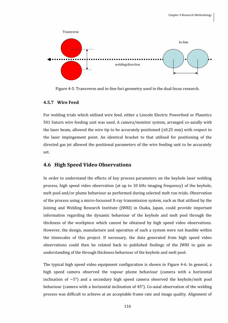
Figure 4-5 Transverse and in-line foci geometry used in the dual focus research 116
List of Figures
12
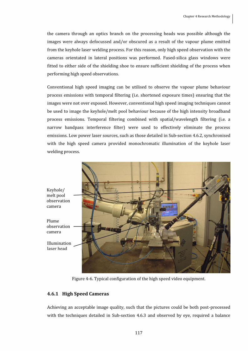
Figure 4-6 Typical configuration of the high speed video equipment 117
Figure 4-7 Pixel extraction points for vapour plume behaviour Note position of points in x-
axis is dependent upon the size of the focussed spot and the incident laser beams cone angle
120
Figure 4-8 Typical configurationposition of the spectrometerrsquos optical fibre end 121
Figure 4-9 Transmission spectrum of the fused-silica glass window 122
Figure 4-10 TIG welds in commercially pure titanium sheet made with successively greater
air contamination of the shielding gas [Smith et al 1999] 123
Figure 9-1 Longitudinal sections of a low porosity weld (4W26 left) and a high porosity weld
(4W24 right) showing how the porosity is predominantly located in the bottom half-
thickness of the weld metal of weld 4W24169
Figure 9-2 Secondary (left) and back scattered (right) electron images of pores in weld
4W24 170
Figure 9-3 Schematic explanation of contrast observed in electron images of pores 170
Figure 9-4 Internal structure of typical pores observed in keyhole laser welded titanium
alloys 171
Figure 10-1 Structure of TWI from the Council to the Executive Board 178
Figure 10-2 TWIrsquos revenue by product [TWI 2010c]179
Figure 10-3 Technology Readiness Level (TRL) scale as used by NASA [NASA 2010] 180
Figure 10-4 The organisational structure of TWI from the Chief Executive down to Groups
and Sections 184
Figure 10-5 The progression of technology innovations at TWI 187
Figure 11-1 A comparison of penetration depth versus specific heat input for multipass C-
GTAW and ATIG welding of titanium [Short 2009] 195
13
List of Symbols
119888 Speed of light
119888119901 Specific heat
119889 Workpiece thickness
119889120572 Absorption depth
119892 Gravitational acceleration constant
119892119890 1198940119899 Electron ion atom and state n degeneracy factor
119893 Planckrsquos constant
119896 Component of the refractive index
119896119887 Boltzmann constant
119896119888 Thermal conductivity
119896119888119904 Thermal conductivity of the solid phase
119896119889 Thermal diffusivity
119896119889119904 Thermal diffusivity of the solid phase
119898 Complex index of refraction
119898119890 Electron mass
119898119892 Particle mass
119899119890 119892 1198940 Electron particle ion and atom density
119901119886119887119897 Ablation pressure
119901119887 Boundary condition constant
119901119892 Hydrostatic pressure
119901119893 Hydrodynamic pressure
119901119907 Vapour pressure
119901120574 Surface tension
119903 Radius
119903119901 Radius of plume particles
119905 Time
119905119898 119907 Time required to reach 119879119898 119907
List of Symbols
14
119906119892 Particle velocity
119907 Frequency of electromagnetic radiation
119907119888119891 Collision frequency between different species
119907119901 Plasma frequency
119908 Beam waist radius of a non-Gaussian laser beam
1199080 Beam waist radius of a Gaussian laser beam
119911 Depth
119860 Absorption coefficient
119860119899119898 Atomic transition probability between states 119899 and 119898
119863 Laser beam diameter at focussing lens
119864119894 Ionisation energy
119864119899 Energy level of state n
119864119907 Vaporisation energy
119865 Focal length of focussing lens
119868 Intensity
119868119899119898 Spectral intensity associated with transition between states 119899 and 119898
1198680 Axial intensity
119871 Latent heat of fusion
1198722 Value of beam quality
119873 Total density of a given state
119873119901 Density of particles in plume
119875 Laser power
119875119890 Peacuteclet number
119875119903 Prandtl number
119876119860119861119878 119864119883119879 119878119862119860 Absorption extinction scattering efficiencies
119877 Beam radius
119877119890 Reynolds number
119877119891 Reflectivity
119877119896 Keyhole radius
119877119896119898 Function of keyhole radius and melt pool radius
11987712 Radii of keyhole curvature
119879119890 Electron temperature
119879119898 119907 Melting vaporisation temperature
1198790 Ambient temperature
119881 Welding speed
List of Symbols
15
119881119887 Terminal velocity as a result of buoyant forces
119883 Melt pool depth
119885(119879119890) Partition function
119885119891 Depth of focus
empty Angle of incidence
120572 Gas ionisation fraction
120572119890119886 Electron neutral atom absorption coefficient
120572119890119894 Electron ion absorption coefficient
120572119894119887 Inverse Bremsstrahlung absorption coefficient
120574 Surface tension coefficient of molten material
120576 Value relating to the material properties and wavelength
120579 Half angle divergence
120583119891 119892 Dynamic viscosity of the fluid and gas
120582 Wavelength
120582119899119898 Wavelength of spectral line associated with photonic emission during
transition between states n and m
120588 Density
120553 Polar angle of melt pool speed
16
List of Abbreviations
ANSI American National Standards Institute
ATIG Activated Tungsten Inert Gas
AWS American Welding Society
BSI British Standards Institution
BPP Beam Parameter Product
BS British Standard
BWRA British Welding Research Association
CFD Computational Fluid Dynamics
CMOS Complementary Metal-Oxide Semiconductor
CRP Core Research Programme
EDX Energy-Dispersive X-Ray
EngD Engineering Doctorate
EPSRC Engineering and Physical Sciences Research Council
FEG Field Emission Gun
FKW Front Keyhole Wall
FZ Fusion Zone
GSP Group Sponsored Project
HAZ Heat-Affected-Zone
ISO International Standards Organisation
JIP Joint Industry Project
JWRI Joining and Welding Research Institute (at Osaka University)
KTIG Keyhole mode Tungsten Inert Gas
LTE Local Thermodynamic Equilibrium
MPI Mean Pixel Intensity
NA Numerical Aperture
NTIS National Technical Information Service
PAW Plasma Arc Welding
RGB Red Green Blue
List of Abbreviations
17
RKW Rear Keyhole Wall
SCP Single Client Project
SEM Scanning Electron Microscopy
SM Single Mode
SSFSW Stationary Shoulder Friction Stir Welding
TEM Transverse Electromagnetic Mode
TIG Tungsten Inert Gas
TRL Technology Readiness Level
TWI The Welding Institute
YAG Yttrium-Aluminium-Garnet
18
Abstract
The University of Manchester Jonathan Edward Blackburn
Doctor of Engineering Understanding Porosity Formation and Prevention when Welding Titanium Alloys with 1microm
Wavelength Laser Beams January 2011
Keyhole laser welding is a joining technology characterised by the high focussed power density applied to the workpiece facilitating deep penetration at high processing speeds High aspect-ratio welds produced using this process invariably have narrow heat-affected-zones and minimal thermal distortion compared with traditional arc welding processes Furthermore the ability to process out of vacuum and the easy robotic manipulation of fibre optically delivered 1microm wavelength laser beams allow keyhole laser welding to process geometrically complex components The widespread uptake of keyhole laser welding for the production of titanium alloy components in the aerospace industry has been limited by the stringent weld quality requirements Producing welds with levels of subsurface weld metal porosity content meeting the required weld quality criteria has been the primary obstacle Here three techniques for controlling the levels of weld metal porosity when welding titanium alloys with NdYAG rod lasers have been developed Characterisation of the welding processes using high speed photography and optical spectroscopy have allowed an original scientific understanding of the effects these methods have on the keyhole melt pool and vapour plume behaviour Combining this with a thorough assessment of the weld qualities produced has enabled the effects of these process behaviours on the formation of weld metal porosity to be determined It was found that with the correct process parameters a directed gas jet and a dual focus laser welding condition can both be used to reduce the occurrence of keyhole collapse during NdYAG laser welding The directed gas jet prevents the formation of a beam attenuating vapour plume and interacts with the molten metal to produce a stable welding condition whereas the dual focus laser welding condition reduces fluctuations in the process due to an enlarged keyhole When applied both techniques reduced the occurrence of porosity in the weld metal of full penetration butt welds produced in titanium alloys A modulated NdYAG laser output with the correct waveform and modulation frequency also reduced the occurrence of porosity in the weld metal compared with welds produced with a continuous-wave output This was a result of an oscillating wave being set-up in the melt pool which manipulated the keyhole geometry and prevented instabilities in the process being established In addition the potential for welding titanium alloys to the required weld quality criteria with state-of-the-art Yb-fibre lasers has been assessed It was found that the high power densities of suitably focussed laser beams with excellent beam quality were capable of producing low-porosity full penetration butt welds in titanium alloys without the techniques required for laser beams with a lower beam quality These new techniques for keyhole laser welding of titanium alloys will encourage the uptake of keyhole laser welding for producing near-net-shape high-performance aerospace components The advantages offered by this joining technology include high productivity low heat input and easy robotic automation
19
Declaration
No portion of the work referred to in the thesis has been submitted in support of an
application for another degree or qualification of this or any other university or other
institute of learning
20
Copyright Statement
The author of this thesis (including any appendices andor schedules to this thesis) owns
certain copyright or related rights in it (the ldquoCopyrightrdquo) and he has given The University of
Manchester certain right to use such Copyright including for administrative purposes
Copies of this thesis either in full or in extracts and whether in hard or electronic copy may
be made only in accordance with the Copyright Designs and Patents Act 1988 (as amended)
and regulations issued under it or where appropriate in accordance with licensing
agreements which the University has from time to time This page must form part of any
copies made
The ownership of certain Copyright patents designs trade marks and other intellectual
property (the ldquoIntellectual Propertyrdquo) and any reproductions of copyright works in the thesis
for example graphs and tables (ldquoReproductionsrdquo) which may be described in this thesis may
not be owned by the author and may be owned by third parties Such Intellectual Property
and Reproductions cannot and must not be made available for use without the prior written
permission of the owner(s) of the relevant Intellectual Property andor Reproductions
Further information on the conditions under which disclosure publication and
commercialisation of this thesis the Copyright and any Intellectual Property andor
Reproductions described in it may take place is available in the University IP Policy (see
httpwwwcampusmanchesteracukmedialibrarypoliciesintellectual-propertypdf) in
any relevant Thesis restriction declarations deposited in the University Library The
University Libraryrsquos regulations (see httpwwwmanchesteracuklibraryaboutus
regulations) and in The Universityrsquos policy on presentation of Theses
21
Acknowledgements
The research presented in this thesis has only been possible as a result of funding from the
Engineering and Physical Sciences Research Council and sponsorship from TWI Ltd These
organisations are gratefully recognised I would like to acknowledge my supervisors Paul
Hilton and Lin Li who successfully applied for the projectrsquos funding in the first instance and
have entertained and provided guidance on my ideas from the outset of the project
The research has greatly benefited from discussions with all my colleagues in the Lasers and
Sheet Processes Section at TWI Ltd past and present and in the Laser Processing Research
Centre at The University of Manchester To name a few but not so many as to make the list
redundant Chris Allen Steve Shi and Ali Khan Several colleagues on the Engineering
Doctorate programme at The University of Manchester for excellent lsquoacademicrsquo discussions
particularly Imdadul Hoque
My brothers Gavin and Richard and all my friends and family for helping me remember that
there are things in life other than research Kym is especially acknowledged for continuously
providing support throughout the duration of this research Finally my parents Steve and
Yvonne for their encouragement of all things I undertake and having confidence in the
majority of them
22
Publications
Portions of the research reported here have been presented in the following publications
Blackburn J Allen C Hilton P amp Li L (2009) rsquoStatistical analysis of low porosity laser
welding of TI alloys using a directed gas jetrsquo Proc ICALEO 2009 Orlando (USA) 172-181
Blackburn J Hilton P Allen C amp Li L (2010) lsquoComparison of high power Yb-fibre and
NdYAG lasers when welding TI-6AL-4Vrsquo Proc PICALO 2010 Wuhan (China) paper 404
Blackburn JE Allen CM Hilton PA Li L Hoque MI amp Khan AH (2010) lsquoModulated
NdYAG laser welding of Ti-6Al-4Vrsquo Sci and Technol of Weld and Joining15(5) 433-439
Blackburn JE Allen CM Hilton PA amp Li L (2010) lsquoDual focus NdYAG laser welding of
titanium alloysrsquo Proc of MATADOR conference Manchester (England) 279-282
Blackburn J Allen C Hilton P amp Li L (2010) lsquoNdYAG laser welding of titanium alloys using
a directed gas jetrsquo J Laser Appl 22(2) 71-78
Blackburn JE Allen CM Hilton PA amp Li L (2011) lsquoDual focus NdYAG laser welding of
titanium alloys effect on porosity formationrsquo Lasers in Engineering under review
Blackburn JE Hilton PA Allen CM Khan A amp Li L (2011) lsquoWelding Ti-6Al-4V with
excellent beam quality 1microm wavelength laser sourcesrsquo under embargo
23
Preface
This thesis is the culmination of four years doctoral research which has focussed on keyhole
laser welding of titanium alloys The research has been predominantly performed at TWI Ltd
the operating arm of The Welding Institute (TWI) based in Abington Cambridge
Experimental research was also performed at The University of Manchester Manchester and
at the Fraunhofer Institut fuumlr Werkstoff- und Strahltechnik (IWS) Dresden
The author completed a Post-Graduate Diploma in Management Sciences from Manchester
Business School during the doctoral research period Prior to performing the above laser
materials processing research the author obtained a MEng (hons) in Mechanical
EngineeringUSA from Lancaster University in July 2005 which incorporated an academic
year spent at Iowa State University of Science and Technology
24
Chapter 1
Introduction
11 Growth of the Laser Materials Processing Industry
The term lsquolaserrsquo is an acronym for lsquoLight Amplification by Stimulated Emission of Radiationrsquo
and refers to the method for producing electromagnetic radiation by the stimulated emission
process Ordinarily the emitted light has a wavelength between the infra-red and ultraviolet
frequencies of the electromagnetic spectrum The term was formulated by Gordon Gould and
first published in 1959 [Gould 1959] in a paper at the Ann Arbor conference of Optical
Pumping Subsequently Maiman [1960] reported the first successful stimulated emission of
electromagnetic radiation in the journal Nature Maiman [1960] utilised a flash-lamp to pump
a ruby crystal and observed stimulated emissions at wavelengths of 6929 and 6943 nm
Previous research performed by Einstein [1916] Ladenburg [1928] Schawlow and Townes
[1958] Javan [1959] and several others formed the basis for the theoretical and practical
knowledge required to produce these stimulated emissions In the same decade as the first
successful demonstration of stimulated emission numerous other laser sources were
developed which utilised active mediums other than the ruby crystal These included the
gallium-arsenic (GaAs) semiconductor laser [Hall et al 1962] the neodymiumyttrium-
aluminium-garnet (NdYAG) laser [Geusic et al 1964] and the carbon dioxide (CO2) laser
[Patel 1964]
In contrast with the light emitted from all other light sources the electromagnetic radiation
emitted from laser sources (commonly known as a laser beam or laser light) is highly
monochromatic - the spectrum of emitted light has a narrow spectral linewidth which is
determined by the bandwidth of the gain medium and the number of longitudinal modes
available in the resonator highly coherent and of very low divergence Published works by
researchers such as Schwarz and DeMaria [1962] and Bahun and Eng-Quist [1962] quickly
Chapter 1 Introduction
25
reported the potential for utilising the laser beam for materials processing applications
including cutting drilling surfacing and welding processes The characteristics of laser light
allow it to be narrowly focussed resulting in a power density suitable for the aforementioned
materials processing applications Focussed beams of light from modern laser sources have
sufficient power density to initiate melting and vaporisation of metallic workpieces thereby
enabling conduction limited and keyhole laser welding to be performed
During the fifty years that have elapsed since the demonstration of the first laser source the
laser materials processing industry has been firmly established through the adoption of laser
technology to improve quality andor productivity in numerous industry sectors Market
figures for 2008 [Belforte 2010] show that $61 Billion of revenue was generated by the sale
of laser systems for materials processing world-wide Approximately 12 by units of the
laser systems sold were for macro welding applications [Belforte 2009]
12 Titanium Usage in Aerospace Applications
Among the commonly utilised metallic materials in the aerospace industry are titanium and
its alloys as their mechanical properties are particularly suitable for the service
requirements of both airframe and aeroengine applications Titanium alloys are already
employed in applications which require corrosion resistance weight or space savings fatigue
resistance or when the capability to operate within a large temperature differential is
required The production of many of these titanium alloy components by traditional
manufacturing methods ie casting or forging andor machining is ordinarily the preferred
method High quality titanium alloy components can be produced with these manufacturing
techniques although the finished components may have buy-to-fly ratios (the mass of
material prior to machining compared with the mass of the finished component) which are
economically unattractive in comparison with aluminium alloys and structural steels It has
been reported that for structural aerospace components the ratio may be 101 [Threadgill et
al 2008] Welding processes offer the potential to manufacture near-net-shape components
which may require post weld machining that will have significantly lower buy-to-fly ratios
and hence reduce material wastage and overall component cost
13 Keyhole Laser Welding
Keyhole laser welding is a non-contact joining process characterised by its high focussed
energy density which is capable of producing high aspect ratio welds (weld widthweld
depth) in many metallic materials It can be performed at atmospheric pressure and with a
Chapter 1 Introduction
26
relatively low heat input compared with inert gas arc welding processes The current
generation of solid-state laser sources (NdYAG Yb-fibre and YbYAG disc lasers) emit laser
light with a wavelength of ~1 microm which can be delivered through optical fibres up to 50 m in
length (depending upon the required beam quality) Consequently the process may be easily
automated using robotic manipulators providing extensive flexibility in terms of part size
and shape when compared with 10 microm wavelength laser electron beam and friction welding
systems Table 1-1 details the key characteristics of keyhole laser welding the reasons the
characteristic occurs and the industrial advantage this gives to the process adopter
Table 1-1 Characteristics of the keyhole laser welding process [Duley 1999 p7 Steen 1998
p151]
Charact-eristic
Reasons why characteristic occurs Industrial significanceadvantage
Hig
h p
roce
ssin
g sp
eed
- laser beam can be narrowly focussed
- very high power laser sources available
- efficient coupling of energy into workpiece
- high productivity potential for cost savings
- possibility for longer weld seams increasing component stiffness
Lo
w h
eat
inp
ut - laser beam can be narrowly focussed
- high intensity heat source making high processing speeds possible
- high aspect ratio (widthdepth) welds
- narrow heat-affected-zone (HAZ)
- minimal thermal distortion
- possibility for simpler clamping
Fle
xib
le p
roce
ss
- can operate at atmospheric pressure
- non-contact process
- autogeneous process or with filler material
- fibre optic delivery of laser beam (wavelength dependent) - easy robotic automation
- fewno component size limitations
- complex welding geometries possible
- variety of joint configurations possible (butt lap t-butt etc)
Rep
eata
bil
ity
- easy robotic automation
- excellent equipment reliability
- laser beam is not affected by magnetic fields
- accurate reliable welding process
Despite the potential advantages for utilising keyhole laser welding as a manufacturing
technique for near-net-shape welding of titanium alloy components if the welding process is
Chapter 1 Introduction
27
to be adopted the produced welds must be of an acceptable quality Of particular concern
when laser welding with 1 microm wavelength laser beams is the formation of porosity in the
weld metal which would reduce the fatigue resistance of the welded joint [Lindh and Peshak
1969] Relatively little research has been published concerning porosity formation and
prevention in laser welded titanium alloys when compared with aluminium alloys and
stainless steels As a result this project was established to bridge this knowledge gap
14 Aim and Objectives
The research presented in this thesis represents a joint project undertaken by The University
of Manchester and TWI Ltd the operating arm of The Welding Institute (TWI) The research
has been funded by the Engineering and Physical Sciences Research Council (EPSRC) by grant
number C537750 and the Industrial Member companies of TWI The research has been
supervised by Paul Hilton Technology Fellow for Laser Materials Processing at TWI Ltd and
Lin Li Head of the Laser Processing Research Centre at The University of Manchester
The aim of this research project was to establish an understanding of the formation of weld
metal porosity when keyhole laser welding titanium alloys with 1 microm wavelength laser sources
and develop techniques which could prevent its formation
Five specific objectives were identified from studies of the background literature to achieve
this aim For completeness the objectives are detailed below but the reasons why these
objectives were chosen are discussed at the end of the Literature Review (where the
objectives are repeated)
a To determine whether an accurately positioned jet of inert gas directed at the laser-
material interaction point can be used for reducing weld metal porosity when welding
titanium alloys relevant to the aerospace industry with an NdYAG laser Furthermore
determine the influence of key process parameters on the resultant weld quality and the
dynamic behaviour of the welding process
b To determine whether a modulated laser power can be used for reducing weld metal
porosity when welding titanium alloys relevant to the aerospace industry with an
NdYAG laser Furthermore determine the influence of key process parameters on the
resultant weld quality and the dynamic behaviour of the welding process
c To determine whether a dual focus laser beam can be used for reducing weld metal
porosity when welding titanium alloys relevant to the aerospace industry with an
NdYAG laser Furthermore determine the influence of key process parameters on the
resultant weld quality and the dynamic behaviour of the welding process
Chapter 1 Introduction
28
d Establish the weld qualities possible when keyhole laser welding titanium alloys
relevant to the aerospace industry with excellent beam quality 1 microm wavelength laser
sources
e Compare the potential benefits for adopting keyhole laser welding as a production
process for titanium aerospace components with the competing manufacturing
processes
15 The Engineering Doctorate Degree
The Engineering Doctorate (EngD) is a postgraduate degree that is more industrially focussed
than a traditional PhD It is offered by numerous universities in the United Kingdom with
each university establishing one or more EngD Academic Centres with a particular research
theme The research theme for the EngD centre at The University of Manchester connected
with this research is ldquoEngineering for Manufacturerdquo Research projects are devised in
collaboration with sponsor organisations and a Research Engineer is recruited for each
project The EngD programme at The University of Manchester is a four year full-time
programme which in addition to a doctoral level research project of the same standard as a
PhD incorporates taught courses and professional development
151 The Research Project
The research project is of the same scientific and technological standard as a traditional PhD
with the chosen topic of research related to an area of strategic importance to the sponsoring
company Three quarters of the four year programme is devoted to the research project with
the Research Engineer taking at least two technical courses to support the research Similarly
to a PhD the EngD requires the submission of a thesis which is examined by viva voce In
addition to examination of the original scientific and technical contributions the thesis is also
examined on its commercial implications
152 The Taught Element
For the EngD at The University of Manchester the taught courses constituted a Postgraduate
Diploma in Management Science administered by Manchester Business School Eight
examined modules were taken in the first two years of the degree which equated to 120
credits or 1200 hr of study The eight modules covered Production Systems Industrial
Relations Managerial Economics Individuals Groups and Organisations Total Quality
Management Logistics and Supply Management Accounting and Marketing Management
The topics are pertinent to the EngD enabling the Research Engineer to understand
Chapter 1 Introduction
29
connections between the research project its commercial drivers and factors which may
impede the successful commercial deployment of the projectrsquos outcome and the commercial
environment in which their industrial sponsors operate
153 Professional Development
The EngD is a professional doctorate and as a consequence it incorporates courses and
workshops to aid the professional development of the Research Engineer Courses and
workshops cover communication skills negotiation skills understanding the management
role effective project management techniques time management techniques industrial law
presentation skills and writing skills Together with the research project and the taught
courses the EngD programme at The University of Manchester is accredited by the Institute
of Mechanical Engineers and the Institute of Engineering and Technology allowing
progression of the Research Engineer to Chartered status by the end of the degree
16 Thesis Structure
This thesis differs from traditional doctoral theses in that it has been submitted in an
alternative format The body of research performed is presented in four parts each in the
style of a peer reviewed journal paper These papers have been prepared for submitted to
accepted for publication or published in a peer reviewed journal Preceding each journal
paper the information regarding the stage of publication is given The primary author of each
paper is the author of this thesis However to avoid uncertainty the specific contribution of
the co-authors is also detailed before each paper In addition portions of the literature review
have been accepted for publication in the academic textbook lsquoWelding and Joining of
Aerospace Materialsrsquo (Ed Professor Mahesh Chatevurdi)
The primary rationale for submitting the thesis in this format is related to the commercial
aspects of the Engineering Doctorate programme As stated above the research performed
has been performed in collaboration with TWI It has been decided that the publication of the
results from this thesis will strengthen the reputation of TWI in the laser welding industry
The motives related to increasing the reputation of the authors of these papers in the laser
materials processing industry are also noted
Nevertheless the structure of this thesis bears a resemblance to that of a traditional doctoral
thesis Proceeding this introductory chapter the Literature Review is given which is
presented in two parts The first part Chapter 2 gives a brief overview of laser welding
highlights the potential defects which may arise when keyhole laser welding titanium alloys
Chapter 1 Introduction
30
and details the weld quality criteria which must be met if keyhole laser welding is to be
utilised by the aerospace industry It is established in Chapter 2 that the formation of porosity
in the weld metal as a result of keyhole instabilities is of primary concern The second part of
the Literature Review Chapter 3 therefore concentrates on the forces which determine the
stability of the keyhole and the mechanisms by which these can be perturbed Potential
solutions for reducing weld metal porosity as a result of controlling the process dynamics are
discussed The majority of the published experimental research has focussed on metals other
than titanium alloys but it is nevertheless valuable and is included Concluding the Literature
Review are the specific objectives of this project which were determined from the knowledge
gaps identified in the Literature Review and the aspirations of TWI Ltd
Following the Literature Review are six chapters detailing the experimental work performed
and the analysis and discussion of the results four of these being peer reviewed journal
papers Chapter 4 describes the materials equipment and experimental procedures used
during this project Chapter 5 details the results of research performed using a directed jet of
argon to control the keyhole laser welding process Chapter 6 covers the results of research
performed with a modulated laser power output In Chapter 7 the results of research
performed with a dual focus laser beam configuration are presented analysed and discussed
The details of research performed with excellent beam quality 1 microm wavelength laser sources
are presented in Chapter 8 Chapters 5-8 contain individual discussions of results Chapter 9
presents and discusses a small number of further results used to analyse the origin of
porosity when keyhole laser welding titanium alloys with 1 microm wavelength laser beams
The commercial aspects and implications of this research are detailed in Chapter 10 and
Chapter 11 Finally the Conclusions of this research and Recommendations for the Future are
given in Chapter 12
31
Part I
Literature Review
Chapter 2 Literature Review Part I An Overview of Laser
Welding Titanium Alloys for Aerospace Applications
Chapter 3 Literature Review Part II Keyhole Behaviour
and the Formation and Prevention of Porosity
32
Chapter 2
Literature Review Part I An Overview of Laser Welding Titanium Alloys for Aerospace Applications
21 Introduction
Potentially this thesis may be accessed by persons unfamiliar with laser materials processing
but who have a specific interest in the joining of titanium and its alloys Consequently this
Literature Review initially provides a brief overview of the interaction between light and
metallic materials and how the absorption of the electromagnetic radiation may be used for
conduction limited laser welding and keyhole laser welding Significantly more attention is
paid to the keyhole laser welding process since the process offers certain key advantages
pertinent to the aerospace industry compared with conduction limited laser welding The
weldability of titanium alloys by the keyhole laser welding process is discussed in terms of
the weld microstructure and potential weld defects Of particular concern when keyhole laser
welding is the formation of porosity in the weld metal which decreases the fatigue life of the
welded joint The potential sources of weld metal porosity when keyhole laser welding are
then detailed
Uptake of the keyhole laser welding process in the aerospace industry is dependent upon the
process being able to produce welds of a quality suitable for their intended application
Therefore the international welding standards relevant to laser welding are compared with a
Chapter 2 Literature Review Part I An Overview of Laser Welding Titanium Alloys for Aerospace Applications
33
company specific standard in order to give an overview of the weld quality criteria that must
be adhered to for certain aerospace applications Finally the potential weld performance
when utilising the current generation of solid-state lasers is reviewed
The majority of literature for this review was identified by performing regular Boolean logic
searches across the following scientific and engineering academic databases Compendex
Inspec Scopus NTIS and Weldasearch Literature was also identified through citations in
published research
22 Laser Light and its Interaction with Metallic Materials
221 Key Characteristics of Laser Light
Laser light has a number of key characteristics it is highly monochromatic has a low beam
divergence and is highly coherent which are conducive to utilising it as a materials
processing tool The design manufacture and integration of the gain medium population
inversion pump and optical resonator will all determine the properties of the emitted
electromagnetic radiation (laser light) When deciding on a laser source for a particular
materials processing application the emission wavelength temporal and spatial operating
modes available output power and beam quality are among the key factors that should be
considered In addition the chosen optics used to guide the laser light to the workpiece will
determine critical parameters such as the beam waist and the depth of focus
The light emitted from the majority of laser sources is highly monochromatic in that the total
spectrum of the light has a very narrow spectral linewidth The exact spectrum is dependent
upon the bandwidth available in the gain medium and the longitudinal modes present in the
optical resonator Laser sources which operate in the continuous-wave mode are capable of
generating a constant power to the workpiece although this may be modulated andor
ramped updown if required so long as it does not exceed the maximum rated output power
of the laser source Conversely pulsed laser sources are capable of generating very high peak
powers for a short duration either through Q-switching or pulsed pumping
The standing longitudinal electromagnetic waves established in the optical resonator may be
separated by varying angles - related to the design of the resonator Constructive and
destructive interference between these longitudinal standing waves give rise to the formation
of an electromagnetic radiation field pattern transverse to the longitudinal waves This is
referred to as the transverse electromagnetic mode (TEMmn where the integers m and n
indicate the number of zero fields in a particular direction) structure of the laser beam which
Chapter 2 Literature Review Part I An Overview of Laser Welding Titanium Alloys for Aerospace Applications
34
determines the intensity distributions perpendicular to the direction of the laser beam
propagation A complete description of the potential TEM modes is outside the scope of this
chapter Nevertheless it can be summarised that laser beams with a higher TEM mode are
more difficult to focus than a laser beam with a lower TEM mode [Steen 1998 p 82] The
TEM00 mode or fundamental mode is the simplest mode and its intensity distribution 119868 as a
function of radius 119903 from the central axis can be theoretically described by a Gaussian
function [Ready 1997 p 41]
119868 119903 = 1198680119890119909119901minus21199032
119908 02 (2-1)
where 1198680 is the axial intensity of the laser beam and w0 is radius of the beam waist
A Gaussian beam radius is usually defined as the radius where its intensity is 1e2 of the axial
irradiance The beam waist is the point in the propagation direction where the laser beam
diameter converges to a minimum and the radius at this point is referred to as 1199080 For a
Gaussian laser beam propagating in free space the beam radius will converge to a minimum
the beam waist before diverging The angle at which the laser beam diverges is termed the
beam divergence angle 2120579 The half-angle divergence 120579 is shown in Figure 2-1 Knowing the
half-angle divergence the beam waist of a Gaussian laser beam can be calculated according to
Equation 2-2 [Ready 1997 p 38]
120579 =120582
1205871199080 (2-2)
Figure 2-1 Two dimensional profiles of three different laser beams of ~1 microm wavelength (a)
BPP = 12 mmmrad 300 mm focal length focussing lens (b) BPP = 6 mmmrad 300 mm focal
length focussing lens (c) BPP = 6 mmmrad 640 mm focal length focussing lens
-15
-10
-05
00
05
10
15
-15 -10 -5 0 5 10 15
Bea
m d
iam
eter
mm
Distance along beam path from beam waist mm
(a)(b)(c)
2w0
θ
Zf (a)
Zf (b) Zf (c)
Chapter 2 Literature Review Part I An Overview of Laser Welding Titanium Alloys for Aerospace Applications
35
The product of the beam waist and the half-angle divergence is a constant and known as the
beam parameter product (BPP) stated in mmmrad Therefore the BPP of a Gaussian laser
beam will be 120582120587 which is the theoretical optimum However the emitted outputs of actual
laser sources are not truly Gaussian although single-mode Yb-fibre and YbYAG disc lasers
are very near and are characterised by measures of their beam quality Perhaps the most
commonly used measure of beam quality is the 1198722 value of the laser beam which compares
the BPP of an actual laser beam to that of a Gaussian laser beam of identical wavelength The
1198722 value of a laser beam is its BPP divided by 120582120587 [International Standards Organisation
2005] For laser sources emitting beams of approximately 1 microm wavelength the BPP is often
utilised as a measure of beam quality Nonetheless both these beam quality values can be
utilised to approximate the propagation of actual laser beams with an expansion of Gaussian
beam analysis Equation 2-3 [Steen 1998 p85] can be utilised to calculate the beam waist
radius w of a real laser beam
119908 =41198722120582119865
120587119877 (2-3)
where F is the focussing lens focal length and 119877 is radius of the beam at the focussing lens
The above equation indicates that laser beams with a smaller value of 1198722 or BPP can be
focussed into smaller diameter spots than those with higher 1198722 or BPP values Another
important factor when determining the characteristics of a laser beam used for a particular
materials processing application is its depth of focus 119885119891 The depth of focus is equal to the
distance travelled in either direction from the beam waist over which the intensity remains
about the same which corresponds to approximately a 5 increase in the beam diameter
Materials processing applications that utilise laser beams with a long depth of focus are less
susceptible to shifts in the focal plane position Equation 2-4 [Havrilla 2002 p16] details the
calculation of the depth of focus for a 5 increase in beam diameter
119885119891 =119908 2
1205821198722 (2-4)
Figure 2-1 details the profiles of three different laser beams all of ~1 microm wavelength It
illustrates that laser beams with lower BPPs may be focussed into smaller beam waists using
the same optical system thereby maintaining an acceptable stand-off distance Conversely a
laser beam with a lower BPP may be focussed into a similar beam waist to that produced with
a laser beam of higher BPP but have a greater depth of focus and an increased stand-off
distance
Chapter 2 Literature Review Part I An Overview of Laser Welding Titanium Alloys for Aerospace Applications
36
222 Absorption by the Solid Phase
Light incident on the surface of a thick opaque metal may be absorbed provided that the
metal has a quantised energy level (electronic atomic or molecular) eg 1198643 minus 1198642 which
matches that of the incident electromagnetic radiation according to Equation 2-5 [Ready
1997 p2]
1198643 minus 1198642 = 119893119907 =119893119888
120582 (2-5)
where 120582 is the wavelength of the incident electromagnetic radiation 119907 is its corresponding
frequency 119893 is Planckrsquos constant and 119888 is the speed of light
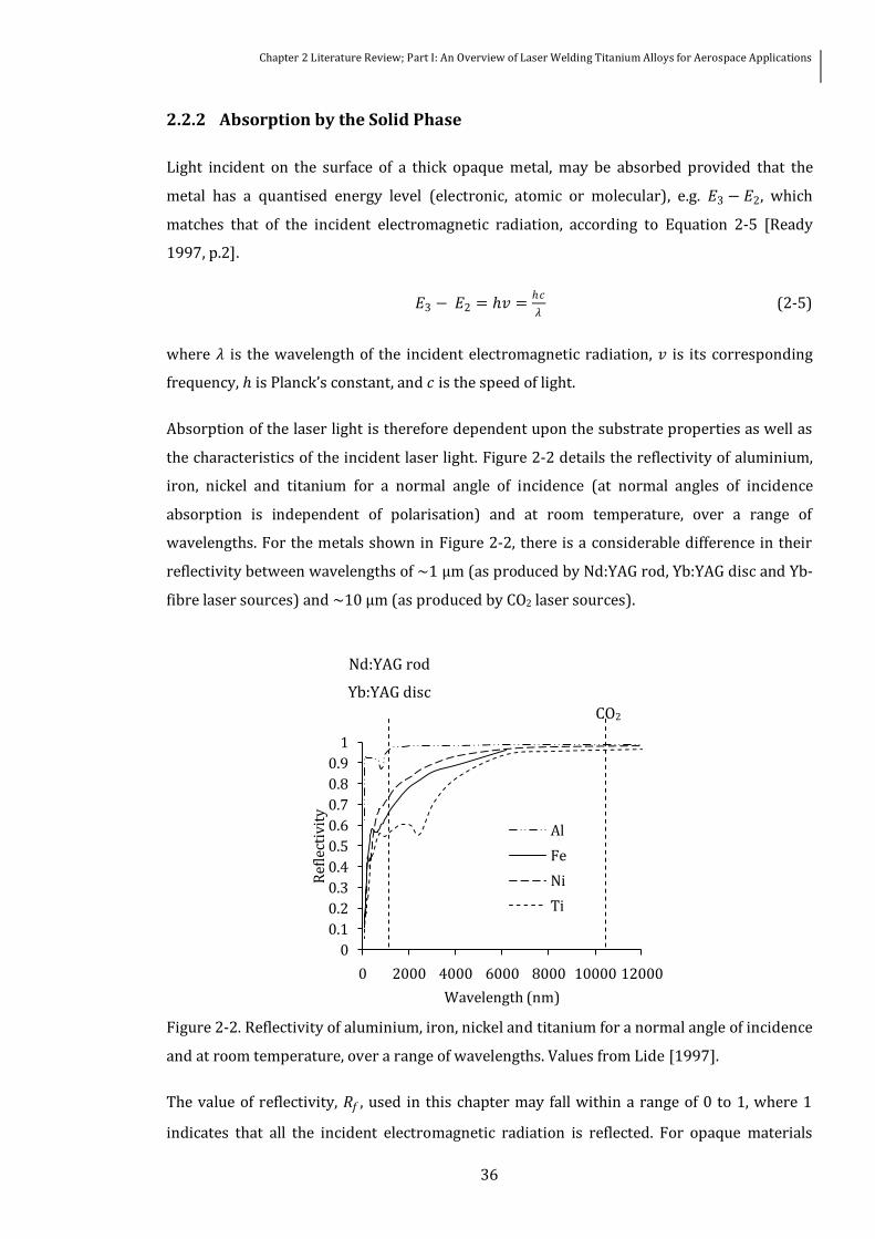
Absorption of the laser light is therefore dependent upon the substrate properties as well as
the characteristics of the incident laser light Figure 2-2 details the reflectivity of aluminium
iron nickel and titanium for a normal angle of incidence (at normal angles of incidence
absorption is independent of polarisation) and at room temperature over a range of
wavelengths For the metals shown in Figure 2-2 there is a considerable difference in their
reflectivity between wavelengths of ~1 microm (as produced by NdYAG rod YbYAG disc and Yb-
fibre laser sources) and ~10 microm (as produced by CO2 laser sources)
Figure 2-2 Reflectivity of aluminium iron nickel and titanium for a normal angle of incidence
and at room temperature over a range of wavelengths Values from Lide [1997]
The value of reflectivity 119877119891 used in this chapter may fall within a range of 0 to 1 where 1
indicates that all the incident electromagnetic radiation is reflected For opaque materials
0
01
02
03
04
05
06
07
08
09
1
0 2000 4000 6000 8000 10000 12000
Ref
lect
ivit
y
Wavelength (nm)
Al
Fe
Ni
Ti
NdYAG rod
YbYAG disc
CO2
Chapter 2 Literature Review Part I An Overview of Laser Welding Titanium Alloys for Aerospace Applications
37
with a smooth surface Equation 2-6 [Steen 1998 p67] can be used to calculate the
reflectivity
119877119891 = 1 minus 119860 (2-6)
where 119860 is the absorptivity or absorption coefficient
The absorption of the incident laser radiation is also dependent upon its angle of incidence
with the metalrsquos surface and the lightrsquos polarisation Figure 2-3 details the effect of the angle
of incidence 120601 on the absorption of the substrate for aluminium and titanium at wavelengths
of 1 and 10 microm The maximum absorption of parallel polarised light by a metal occurs at the
Brewster angle which is wavelength and material dependent This may be significant in
terms of weld penetration [Sato et al 1996] and weld quality [Graumlf et al 2010] when welding
with laser sources whose output is polarised in a certain direction such as CO2 lasers The
laser light emitted from the majority of modern multi-mode solid-state laser sources such as
Yb-fibre and YbYAG disc lasers is randomly polarized
(a) (b)
Figure 2-3 Absorption coefficients of aluminium and titanium at room temperature for
parallel (p) and perpendicular (s) polarisation as a function of the angle of incidence Oslash and
for (a) 10 microm wavelength and (b) 1 microm wavelength Note different y-axis scales Values from
Lide [1997]
The proportion of electromagnetic radiation absorbed by the substrate will change during the
interaction time since the absorption is also dependent upon the temperature as shown for a
laser of 106 microm wavelength in Figure 2-4 for aluminium copper and tin As the temperature
of the solid metal rises there is a steady increase in absorptivity Subsequently the
absorptivity rises appreciably at the materials melting point In keyhole laser welding the
absorption of the incident electromagnetic radiation will increase extensively either through
0
01
02
03
0 15 30 45 60 75 90
Ab
sorp
tio
n
Angle of incidence Oslash
Al p polarisation
Al s polarisation
Ti p polarisation
Ti s polarisation
0
01
02
03
04
05
06
07
08
0 15 30 45 60 75 90
Ab
sorp
tio
n
Angle of incidence Oslash
Chapter 2 Literature Review Part I An Overview of Laser Welding Titanium Alloys for Aerospace Applications
38
multiple Fresnel absorptions at the keyhole walls or through inverse Bremsstrahlung
absorption
Figure 2-4 Change in reflectivity of aluminium copper and tin during interaction with a 106
microm laser at a normal angle of incidence as a function of temperature Values from Bruumlckner et
al [1989 1991]
Equation 2-7 indicates the depth of absorption 119889120572 over which the absorbed intensity
reduces by 1e2 The absorption depth of metals is typically less than the wavelength of the
incident electromagnetic radiation since the 119896 value of the refractive index is greater than 1
and therefore the laser beam can be initially treated as a surface heat source for metallic
substrates [Duley 1999 p68]
119889120572 = 120582
4120587119896 (2-7)
223 Conduction and Melting
At very low values of applied laser intensity there will be insufficient energy deposited at the
surface of the substrate for a phase transition from solid to liquid to take place The rate at
which this thermal energy diffuses through the substrate is characterised by the materialrsquos
thermal diffusivity 119896119889 a property which is related to the thermal conductivity 119896119888 the specific
heat 119888119901 and the density 120588 of the material If the intensity of the laser radiation incident on
the substrate is increased sufficiently (~102 Wmm-2 for most metals) surface melting will
begin to occur and a pool of molten material will form The depth of the melt pool 119883 can be
09
091
092
093
094
095
096
097
098
099
1
300 500 700 900 1100 1300 1500
Ref
lect
ivit
y
Temperature K
Al
Cu
Tin
Melting point Tin
Melting point Al
Melting point Cu
Chapter 2 Literature Review Part I An Overview of Laser Welding Titanium Alloys for Aerospace Applications
39
approximated by Equation 2-8 [Cohen 1967] under the assumption that the thermal
conductivity and diffusivity in the solid and liquid phases are nominally identical
119883 119905 asymp016119875(119905minus119905119898 )
120588119871 (2-8)
where 119905 is the time the laser radiation is applied for 119905119898 is the time required to reach the
melting temperature 119879119898 at the surface of the workpiece 119875 is the absorbed laser power
density and 119871 is the latent heat of fusion
The time taken to for the surface of the substrate to reach its melting temperature can be
approximated by Equation 2-9 [Cohen 1967]
119905119898 =120587119896119888119904
21198791198982
4119870119889119904 1198682 (2-9)
where 119896119888119904 and 119896119889119904 are the thermal conductivity and thermal diffusivity of the solid phase
224 Vaporisation
Vaporisation of metallic substrates can occur at applied intensities as low as 102 Wmm-2 if the
interaction time is sufficient However applied laser intensities exceeding 104 Wmm-2 are
often used to achieve vaporisation of the surface for materials processing applications such as
keyhole laser welding laser cutting and laser drilling Equation 2-10 [Ready 1997 p322] can
be utilised to estimate the time taken 119905119907 to reach the vaporisation temperature 119879119907 of the
substrate
119905119907 =120587119896119888120588119888119901(119879119907minus 1198790)2
41198752 (2-10)
where 1198790 is the ambient temperature
This initial vaporisation of the substrate creates a depression in the molten pool through the
recoil pressure exerted by the vapour thereby forcing the molten metal to the peripheries of
the interaction area It is a critical stage in the formation of a vapour cavity in the substrate
as it leads to a significant reduction in reflectivity Efficient coupling of the laser beam into the
substrate is then achieved either through multiple Fresnel absorptions by the molten
material (for 1 microm wavelength laser sources) For wavelengths of the order of 10 microm the
absorption method is more complex Absorption of the incident laser energy by free-free
electrons (inverse Bremsstrahlung absorption) is possible at this wavelength as is Fresnel
absorption The proportion absorbed by each mechanism is a function of the welding
Chapter 2 Literature Review Part I An Overview of Laser Welding Titanium Alloys for Aerospace Applications
40
parameters [Solana and Negro 1997] Inverse Bremsstrahlung absorption can be neglected
for 1 microm wavelength Figure 2-5 details the formation of a vapour cavity through a series of
co-axial high speed images taken when a laser beam emitted from an NdYAG rod laser was
incident on a plate of Ti-6Al-4V
(a) (b) (c) (d) (e)
Figure 2-5 Formation of a vapour cavity in Ti-6Al-4V using an NdYAG rod laser (a) surface
melting (b) - (c) vaporisation of the substrate occurs molten metal is pushed to the
peripheries and absorption of the laser beam significantly increases and (d) ndash (e) this leads
to the formation of a high aspect ratio vapour cavity
225 Plasma Formation
Above it was discussed that the formation of a keyhole in a substrate with a laser beam is
dependent on the vaporisation of the substrate For laser beams of ~10 microm wavelength the
metallic vapour may become ionised and the radiation is efficiently absorbed via the inverse
Bremsstrahlung absorption process The proportion of incident radiation absorbed by the
plasma a gas which is constituted of both electrons and ions depends upon the ratio of the
electron ne and ion density ni to the density of the vapour atoms no This can be calculated
by Equation 2-11 [Mitchener and Kruger 1973 p43] if the gas is assumed to be in local
thermodynamic equilibrium (LTE)
119899119890119899119894
1198990= (
119892119894119892119890
1198920)
2120587119898119890119896119887119879119890 32
1198933 exp
E ikb T e
(2-11)
where 119896119887 is the Boltzmann constant 119898119890 is the electron mass 119864119894 is the ionisation energy of
the gas 119892119890 119894 0 are the degeneracy factors of the electrons ions and neutral atoms respectively
and 119879119890 is the electron temperature
It is possible that a plasma may form above the keyhole and attenuate the incident laser
radiation either through inverse Bremsstrahlung absorption or defocussing as a result of a
gradient electron density and lead to a reduction in depth of the keyhole [Poueyo-Verwaerde
et a 1993] For laser beams of ~1 microm wavelength inverse Bremsstrahlung absorption of the
laser beam is not a concern However it has been shown that when welding with an NdYAG
Chapter 2 Literature Review Part I An Overview of Laser Welding Titanium Alloys for Aerospace Applications
41
rod laser the beam can be attenuated and defocussed by a vapour plume of nano-scale
particles [Greses 2003] causing a reduction in penetration depth or keyhole instabilities
23 Laser Welding Fundamentals
The absorption of laser light by a metallic substrate and the conduction of the resultant
thermal energy leading to possible phase changes in the substrate were detailed in the
previous Section These potential phase changes can be utilised to distinguish between the
two fundamental modes of laser welding (i) conduction limited and (ii) keyhole Only solid-
liquid and liquid-solid phase changes occur when laser welding in the conduction limited
mode whereas during keyhole laser welding a portion of the substrate is vaporised and
hence the gaseous phase is also present Furthermore as discussed above there is the
potential for plasma to be present when keyhole laser welding Laser welding can be utilised
to weld a number of metallic materials including carbon steels stainless steels nickel alloys
aluminium alloys magnesium alloys titanium alloys and copper Certain combinations of
dissimilar metals may also be joined by keyhole laser welding with the rapid cooling rates
allowing segregation and grain growth to be reduced
This chapter is primarily concerned with keyhole laser welding since if the process is
optimised it is more advantageous to laser weld typical grades and thicknesses of metallic
aerospace materials in the keyhole mode than in the conduction limited mode Principally
this is a result of the lower heat-input and increased processing speeds possible when
keyhole laser welding
231 Conduction Limited Laser Welding
Conduction limited laser welding involves only the solid and liquid phases of the substrate
and consequently the energy from the incident laser radiation is only absorbed by the surface
of the substrate Subsequently this thermal energy is transferred from the surface into the
bulk of the substrate via thermal conduction Melting occurs when the applied intensity is
sufficient and a weld is made when the molten material solidifies When conduction limited
laser welding the resultant penetration depth is heavily influenced by the Marangoni forces
or forces due to a surface tension gradient Conduction limited laser welding can be used to
produce spot or seam (either through overlapping spots or a continuous process) welds
Since the process relies solely on conduction the weld depths possible are limited by the
thermal conductivity of the substrate A power density of approximately 102 ndash 104 Wmm-2 is
ordinarily sufficient for conduction limited welding to be performed The resulting fusion
Chapter 2 Literature Review Part I An Overview of Laser Welding Titanium Alloys for Aerospace Applications
42
zone has a hemispherical weld profile with a width exceeding the depth by a factor of ~2
shown in Figure 2-6 A significantly larger HAZ (shown in Figure 2-6) compared with welds
made using keyhole laser welding also occurs
Figure 2-6 Conduction limited laser autogeneous melt run in 8 mm thickness 2024
aluminium alloy produced with the laser beam emitted from an NdYAG rod laser source
(scale in mm) Courtesy of TWI Ltd
Table 1-1 summarises the characteristics and subsequent advantages of utilising keyhole
laser welding in an industrial environment The advantages associated with the flexibility and
repeatability of the process are also valid for conduction limited laser welding However the
heat inputted to the workpiece when operating in the conduction regime is significantly
higher than when operating in the keyhole regime Furthermore processing speeds are
significantly lower for a given material and thickness In comparison with keyhole laser
welding conduction limited laser welding is an inherently stable process As will be discussed
in the subsequent Section defects arising from instabilities in the vapour cavity such as
porosity are not formed in conduction limited laser welds High integrity welds with few or
no defects can therefore be more easily produced when conduction limited laser welding
For conduction limited spot welds Equation 2-8 can be utilised to approximate the depth of
penetration This equation is subject to certain boundary conditions so that only parameters
which cause melting are chosen It has been reported [Williams et al 2001] that fully
penetrating welds in aluminium alloy (2000 series) at least 635 mm in thickness can be
produced by conduction limited laser welding if the focussed intensity is optimised such that
the surface temperature of the melt pool is just below the vaporisation temperature
Accurate control of the melt pool temperature and hence the heat input is required to ensure
the penetration depth remains constant and no penetration spiking occurs Figure 2-2 and
Chapter 2 Literature Review Part I An Overview of Laser Welding Titanium Alloys for Aerospace Applications
43
Figure 2-3 show that the absorption of the laser beam by a particular substrate is dependent
upon the wavelength of the beam and its angle of incidence with the workpiece A result of
this is that laser beams of wavelengths le 1 microm are more suited to conduction limited welding
of metallic substrates since they are more readily absorbed than longer wavelength laser
beams Operation at an angle of incidence equal to the Brewster angle of a particular laser-
beam material combination will further increase absorption of the beam by the substrate It is
also known that the proportion of the incident laser light absorbed is a function of the
temperature of the substrate (see Figure 2-4) An accurate knowledge of the temperature-
absorptivity relationship as well as the temperature dependent values of thermal
conductivity and effective viscosity would allow an approximate heat input to be calculated
[De and Debroy 2006] Furthermore it is critical that the temperature of the substrate does
not exceed its vaporisation temperature as this would result in a significant increase in
absorption of incident laser light and the formation of a vapour cavity However in practice
temperature-absorptivity relationships are not known and it is not feasible to determine
them Real time monitoring and feedback of the melt pool temperature is a possible approach
to controlling penetration depth when conduction limited laser welding [Bardin et al 2005]
232 Keyhole Laser Welding
Keyhole laser welding (also referred to as deep penetration laser welding) is similar in
concept to electron beam welding in that a vapour cavity is formed in the substrate and
subsequently traversed across it A liquid sheath surrounds the vapour cavity or keyhole
which is in turn surrounded by the solid substrate The keyhole is primarily maintained by
the ablation pressure and the pressure of the vapour within it A portion of this vapour is
ejected from the keyhole and therefore a steady-state cannot be achieved with a stationary
keyhole as ultimately it will fully penetrate the substrate and the vaporised material that is
ejected cannot be replenished to sustain the vapour pressure However a quasi steady-state
can be considered for a moving keyhole As the keyhole is traversed through the substrate
the sheath of molten material surrounding it is continuously transported from the region in
front of the keyhole to the trailing melt pool
The dominant transportation process is the flow of molten material around the keyhole
although a proportion of the molten material is vaporised and transported across the keyhole
maintaining the vapour pressure and potentially producing a quasi steady-state Thermal
conduction in the direction of travel ensures the continuous replenishment of the molten
material Figure 2-7 shows the formation of the keyhole laser welding process in C-Mn steel
and a schematic of the keyhole and molten pool geometries
Chapter 2 Literature Review Part I An Overview of Laser Welding Titanium Alloys for Aerospace Applications
44
(a) (b) (c) (d)
(e)
Figure 2-7 Formation of keyhole laser welding process in C-Mn steel (a) surface melting (b)
vaporisation of substrates occurs (c) keyhole traverses across the workpiece and melt pool
begins to form and (d) the melt pool length increases and stabilises (e) schematic of the side
view of a keyhole
The keyhole is not cylindrical in shape and has a characteristic curve to it which is
determined by the absorption mechanism travel speed and thermal conductivity of the
substrate Analogous to conduction limited laser welding keyhole laser welding can be
utilised for either spot or seam welding Typically a continuous process is employed to
maximise the potential advantages of the process although pulsed laser sources are
particularly suited to spot welding applications Characteristic profiles of keyhole laser welds
produced in Ti-6Al-4V with a 1 microm wavelength laser source are shown in Figure 2-8
(a) (b)
Figure 2-8 Profiles of keyhole laser welds produced in Ti-6Al-4V (a) 93 mm thickness and
(b) 32 mm thickness Note different scales Courtesy TWI Ltd
Table 1-1 summarises the characteristics and subsequent advantages of utilising keyhole
laser welding in an industrial environment Disadvantages associated with keyhole laser
welding include
molten pool
keyhole
front keyhole wall
solidified weld metalrear keyhole wall
welding direction
2mm
1mm
Chapter 2 Literature Review Part I An Overview of Laser Welding Titanium Alloys for Aerospace Applications
45
1 Equipment cost ndash the initial cost of high power laser sources can be high compared
with arc welding equipment This is ordinarily offset by an increase in productivity
Recent advances in solid-state laser technology are driving down initial costs as well
as increasing wall plug efficiency
2 Safety ndash absorption of laser radiation by the skin and in particular the retinal hazard
region is of great concern The exact safety measures are dependent on wavelength
and power BS EN 60825-12007 or ANSI Z1361-2007 should be referred to for exact
safety requirements
3 Joint fit-up requirements ndash narrowly focussed laser beams may stray from the
required joint line through workpiece misalignment or thermal distortion This
tolerance can be increased by using hybrid laser-arc welding or a seam tracking
system
Power intensities of ~104 Wmm-2 and above are ordinarily sufficient for a keyhole to be
initiated in the substrate although vaporisation is possible at lower power densities if the
values of welding speed and thermal conductivity of the substrate are conducive Equation 2-
12 [Qin et al 2007] can be utilised to approximate the critical power required for keyhole
laser welding with a Gaussian beam as a function of welding speed 119881
119875 = 120588120587(2119896119889119881)1
21199080
3
2119864119907 (2-12)
where 119864119907 is the energy required to vaporise the material
This relationship should be treated as an approximation only since it is known from
empirical evidence that oscillations in the keyhole behaviour may occur even with a constant
set of parameters [Arata et al 1984] making a quasi steady-state particularly difficult to
achieve Variations in the keyhole and melt pool behaviour may lead to certain weld defects
such as intermittent penetration and weld metal porosity Consequently the formation and
subsequent dynamic behaviour of a keyhole has been the subject of intense theoretical and
practical investigations (eg Arata et al 1984 Kaplan 1994 Dowden et al 1995 Matsunawa
et al 1998 and Fabbro and Chouf 2000) Thorough details of the keyhole and melt pool
dynamics is particularly extensive and challenging and the published investigations of the
aforementioned researchers should be referred to for an excellent understanding of this area
Fundamentally the transient behaviour of the keyhole is dependent upon the forces acting to
maintain it and those tending to close it Duley [1999 p83] summarised that the forces
maintaining the keyhole are the evaporative and radiative pressures whilst those acting to
Chapter 2 Literature Review Part I An Overview of Laser Welding Titanium Alloys for Aerospace Applications
46
close it are the hydrostatic and hydrodynamic pressures of the surrounding molten material
and its surface tension
Optimisation of the process parameters is critical if high quality welds are to be produced
with the keyhole laser welding process Table 2-1 specifies the critical process parameters
that should be considered when keyhole laser welding either autogenously or with filler
material A significantly more extensive list can be found in BS EN ISO 15609-42009
lsquoSpecification and qualification of welding procedures for metallic materials Welding procedure
specification Laser beam weldingrsquo Further process parameters will emerge if more
complicated processes are chosen such as hybrid laser-arc welding and dual focus keyhole
laser welding
Table 2-1 Potential process parameters for keyhole laser welding [Duley 1999 p28 Steen
1998 p156]
Type Parameters
Las
er s
ou
rce
focu
ssed
bea
m wavelength polarisation
power welding speed
focussed spot size focal plane position
beam quality depth of focus
stand-off distance pulse energy (pulsed laser)
pulse time (pulsed laser) pulse shape (pulsed laser)
pulse frequency (pulsed laser) waveform (modulated output)
frequency (modulated output) duty cycle (modulated output)
Wo
rkp
iece
surface preparation shielding gas type
joint geometry shielding gas arrangements
jiggingfixturing
Fil
ler
mat
eria
l
chemical composition feed rate
type (wire or powder)
gaugediameter
position with respect to welding process
24 Laser Weldability of Titanium Alloys
Titanium weld metallurgy is controlled by the transformation from the close-packed-
hexagonal structure (α phase) into the body-centred-cubic crystalline structure (β phase)
Chapter 2 Literature Review Part I An Overview of Laser Welding Titanium Alloys for Aerospace Applications
47
which occurs at the β transus temperature (882degC) The allotropic transformation is
reversible and the transus temperature can be manipulated with the alloying of α (eg
aluminum carbon nitrogen and oxygen) andor β (eg chromium copper iron and
molybdenum) phase stabilisers whereby
the addition of β phase stabilisers decrease the β transus temperature such that the β
phase can be retained as the weld cools to ambient temperature and
the addition of α phase stabilisers increases the β transus temperature promoting the
formation of the α phase
The majority of titanium alloys are considered readily weldable often determined by the
ductility and toughness of the as-welded zone by fusion welding processes Ordinarily the
higher strength alloys are more difficult to weld as a result of [Luumltjering and Williams 2007
p105]
the alloys forming microstructures of poor toughness and low ductility and
containing eutectoid alloying elements eg chromium and iron which may cause
liquation cracking
During fusion welding the temperature of the fusion zone and also a portion of the heat
affected zone is above the β transus temperature and consequently may exhibit β
transformed microstructures and properties The microstructure of fusion welds in titanium
alloys is ordinarily martensitic which in comparison with martensite formed in stainless
steels has a higher toughness and a decreased susceptibility to cracking [Yunlian et al 2000]
Cooling rates above 410degCs-1 are necessary to achieve a completely martensitic structure in
Ti-6Al-4V [Ahmed and Rack 1998] These cooling rates are easily obtainable when keyhole
laser welding and the weld metal will undergo a particularly fast thermal cycle compared
with inert gas arc welding consequently producing a finer martensitic microstructure which
will have a smaller content of alloying elements [Costa et al 2007 Yunlian et al 2000] The
required cooling rates to obtain a martensitic structure will be different for all grades of
titanium For commercially pure titanium a similar trend to the above Ti-6Al-4V
microstructure has been reported [Li et al 2009] ndash increased cooling rates lead to an
increased content of fine-grained acicular αrsquo present in the fusion zone
Despite the high cooling rates promoting a fine grained martensitic structure in keyhole laser
welding of titanium alloys the potential still exists for a number of defects to occur including
weld bead embrittlement cracking geometrical defects in the profile and weld metal
porosity
Chapter 2 Literature Review Part I An Overview of Laser Welding Titanium Alloys for Aerospace Applications
48
241 Embrittlement
Titanium has an elevated affinity for light elements (such as hydrogen nitrogen and oxygen)
at temperatures exceeding 500degC which may result in embrittlement of the weld metal if
they are absorbed The discoloration of the weld metal can be utilised as an indicator of the
shielding adequacy whereby the weld metal follows the colour sequence [American Welding
Society 2001] silver (indicating no discoloration) light straw dark straw bronze brown
violet green blue gray and white (indicating heavy discoloration and embrittlement) This
discoloration is directly related to the degree of weld metal embrittlement and hardness of
the weld metal
The effects of oxygen contamination (0001 to 10) in argon shielding gas was studied by Li
et al [2005] when laser welding commercially pure titanium At increased oxygen contents
the weld bead discoloration followed the sequence outlined in AWS D171 and which also
corresponded to a change in the surface hardness Table 2-2 details the hardness data
reported by Li et al [2005] However it is imperative that the weld bead discoloration not be
utilised as an inspection tool for shielding adequacy as the discoloration sequence will repeat
as the oxidation thickness increases [Talkington et al 2000]
Table 2-2 Surface colour and hardness of NdYAG laser welds made in 05 mm thickness
commercially pure titanium sheets with varied oxygen content in the argon shielding gas [Li
et al 2005]
Oxygen content Surface colour Hardness Hv
0 Silver 242plusmn11
015 Straw 246plusmn16
05 Dark straw 247plusmn13
15 Dark strawpurple 254plusmn20
20 Dark strawpurpleblue
282plusmn18
30 Purpleblue 295plusmn16
50 Blue 323plusmn15
100 Blue 373plusmn20
To avoid embrittlement titanium alloys are ordinarily shielded with a high-purity inert gas
when they are keyhole laser welded For reasons related to its ionisation energy and the
formation of a beam attenuating plasma (see Section 35) helium is utilised when welding
with a 10 microm wavelength focussed laser beam whereas argon is used when welding with a 1
Chapter 2 Literature Review Part I An Overview of Laser Welding Titanium Alloys for Aerospace Applications
49
microm wavelength focussed laser beam The shielding gas is often delivered through a trailing
shield which covers the weld face and through an efflux channel covering the weld root At
sufficiently slow welding speeds the shielding gas may be delivered through a co-axial or
lateral nozzle This approach is often employed when laser welding titanium alloys with a
pulsed laser source
242 Cracking
Titanium alloys are in general not considered susceptible to solidification cracking since
they contain low concentrations of impurities However research has suggested [Inoue and
Ogawa 1995] that titanium alloys may be vulnerable to solidification cracking if they are
incorrectly restrained during welding It is likely that the degree of vulnerability is related to
the amount of back diffusion of solute-elements in the solid [Inoue and Ogawa 1995] Of
more concern when welding titanium alloys is contamination cracking which may occur if
the weld metal is exposed to light elements at temperatures exceeding 500degC or iron particles
during welding When absorbed the light elements such as hydrogen nitrogen and oxygen
will migrate to interstitial sites and may cause cracking as a result of the welding stresses
Particularly high levels of these elements are required in the welding atmosphere for
example 3000 ppm oxygen in the weld metal may cause transverse cracking [Donachie 2000
p88] As previously the presence of light elements in the vicinity of the welding process and
cooling weld bead may be reduced by utilising an effective trailing shield and a high-purity
inert shielding gas with a low dew point Particles of iron on the workpiece may be dissolved
into the melt pool and potentially cause embrittlement of the weld metal [Donachie 2000
p88] An appropriate materials preparation and handling procedure will minimise the risk of
iron particle contamination
243 Geometrical Weld Profile Defects
Geometrical defects in the weld profile such as undercut and concavity at the weld face or
root are particularly undesirable for components subject to dynamic loading The defects
may act as stress concentrators and subsequently be initiation sites for fatigue cracks
Fundamentally the defects can either be attributed to the laser welding process or to the
joint configurationrestraint For instance joint misalignment where the laser beam wanders
from the joint line resulting in a portion of the weld seam not being welded is an example of a
defect which is not related to the welding process It may occur when the laser beam is not
correctly aligned with the joint line or when the component is not correctly clamped allowing
movement of the joint during welding Consequently this defect is more commonly observed
Chapter 2 Literature Review Part I An Overview of Laser Welding Titanium Alloys for Aerospace Applications
50
in keyhole laser welding as the finely focussed beams are more susceptible to missing the
joint line than in conduction limited laser welding Incorrect joint configurationrestraint
errors in gap fit up or inadequate machining of the abutting edges may lead to other
geometrical defects in the weld profile specifically [Duley 1999 p202] burn through drop
out or a loss of penetration
The above defects can be eliminated through the adoption of adequate weld clamping and
workpiece preparation Geometrical weld profile defects associated with the laser welding
process such as humping undercut and concavity may occur as a consequence of incorrect
welding parameters Often a balance of process parameters is found to achieve the required
weld penetration and minimise weld profile defects Figure 2-9 [Hilton et al 2007] details the
terminology adopted in this project for defining the weld profilersquos geometry and defects
Figure 2-9 Potential weld profile defects and terminology [Hilton et al 2007]
Humping which is not shown in Figure 2-9 refers to the formation of ellipsoidal swellings in
the top bead of a weld The swellings are severely undercut and are separated by an
elongated concavity along the weld face Humping is ordinarily observed when particularly
high welding speeds and laser powers are adopted For example humping was observed at
speeds above 20 mmin-1 when using a 4 kW laser power focussed into a 600 microm beam
diameter for welding of 3 mm thickness 304L stainless steel [Fabbro et al 2007]
Defects in the weld profile which cannot be eliminated through alteration of process
parameters may be removed by further processing andor machining Filler material either
powder or wire may be added during the process or a low-power cosmetic pass utilised to
re-shape the top bead Workpieces which are thicker at the joint could be used which would
allow post-weld machining to eliminate the defects without having an undersized weld
Ca = Face undercut
ca = Root undercut
Cr = Face concavity
cr = Root concavity
r = Excess penetration
R = Excess weld metal
L = Face weld width
I = Root weld width
I0 = Minimum weld width
Chapter 2 Literature Review Part I An Overview of Laser Welding Titanium Alloys for Aerospace Applications
51
244 Weld Metal Porosity
It has been reported [Matsunawa et al 2001] that weld metal porosity can easily form when
keyhole laser welding This is a concern for high-performance components that are in cyclic
loading as the pores will reduce its fatigue resistance Figure 2-10 reproduced from Lindh
and Peshak [1969] indicates the significant decrease in fatigue life of Ti-6Al-4V welds
containing weld metal porosity compared with defect free welds Porosity is of primary
concern for components whose weld profiles are dressed (to remove geometrical defects in
the weld profile etc) as pores will break the surface act as stress concentrators and further
reduce the fatigue resistance of the weld as indicated in Figure 2-10
Figure 2-10 Fatigue behaviour of welds in Ti-6Al-4V showing the effect of surface and
subsurface weld metal porosity in comparison with defect free welds Reproduced from
Lindh and Peshak [1969]
A significant amount of research has been performed into the causes of porosity when laser
welding metallic materials although only a small proportion of this concerns the formation of
porosity when processing titanium alloys The majority of the reported fundamental
investigations have been performed on aluminium alloys and ferrous metals Potential
sources of porosity when laser welding titanium alloys are from
The presence of excessive hydrogen in the melt pool which is rejected upon
solidification and subsequently trapped in the solidifying melt pool
Instabilities in the welding process leading to the entrapment of shielding gases
andor metal vapour
0
100
200
300
400
500
600
700
800
900
10000 100000 1000000 10000000
Max
imu
m N
et S
tres
s M
Pa
Cycles to Failure
Defect Free Sub-surface Porosity Surface Porosity
Chapter 2 Literature Review Part I An Overview of Laser Welding Titanium Alloys for Aerospace Applications
52
2441 Hydrogen Porosity
Figure 2-11 details the solubility of hydrogen in titanium as a function of temperature
reproduced from Lakomski and Kalinyuk [1963] The overall trend of this relationship is an
increasing solubility with a decreasing temperature Ordinarily this would not result in the
rejection of hydrogen from the solidifying melt pool and the formation of porosity However
at the solidification temperature there is a significant drop in hydrogen solubility which may
lead to weld metal porosity
Figure 2-11 The solubility of hydrogen in titanium as a function of temperature Reproduced
from Lakomski and Kalinyuk [1963]
Figure 2-11 indicates that hydrogen will be rejected if the content is greater than ~210
ml100g (280 ppm) which may result in the formation of hydrogen bubbles and
subsequently porosity The hydrogen content of modern titanium alloys is generally lt280
ppm and therefore will not pose a problem on its own However other potential sources of
hydrogen exist when laser welding titanium which will if not properly addressed contribute
towards the total amount of hydrogen in the melt pool Specifically these other potential
sources of hydrogen may be from
the hygroscopic titanium oxide layer present on the workpiece surfaces
shielding gas(es)
welding consumable(s) and
workpiece preparation
0
50
100
150
200
250
300
350
400
450
500
1200 1400 1600 1800 2000 2200 2400 2600 2800 3000 3200 3400
Solu
bil
ity
ml
10
0 g
Temperature degC
Tmelting Tboiling
Chapter 2 Literature Review Part I An Overview of Laser Welding Titanium Alloys for Aerospace Applications
53
Titanium oxide will form on the surface of titanium alloys if sufficient levels of oxygen are
present in the media surrounding it This self-healing oxide layer gives titanium its excellent
corrosion resistance to different types of aggressive media However the oxide layer has a
hygroscopic behaviour and will consequently adsorb moisture from the atmosphere under
ambient conditions Removal of the hydrated layers prior to welding is critical in minimising
the potential hydrogen content of the melt pool Consequently the effectiveness of the
method used to remove the hydrated layer and other surface contaminants (for example oil
dirt and grease) may have a large influence on the formation of weld metal porosity
Mechanical cleaning methods such as scratch brushing and abrasive cleaning are often
utilised because they are relatively straight forward processes compared with chemical
pickling Mueller et al [2006] produced welds with small amounts of weld metal porosity
when laser welding 635 mm thickness Ti-6Al-4V if the joint was cleaned with a stainless
steel brush prior to welding It should be noted there is a slight risk of iron pick up with
stainless steel brushes and titanium brushes should be used for critical applications [Smith et
al 1999] Autogeneous melt runs and butt welds with very low levels of porosity were also
produced in titanium alloys up to 93 mm in thickness by Hilton et al [2007] In this work the
surfaces were cleaned with an abrasive pad and acetone degreased prior to welding and
abutting joint edges of butt were also dry machined However it should be noted that in both
of the above publications [Mueller et al 2006 Hilton et al 2007] a directed gas jet was also
used to achieve the low levels of weld metal porosity (see Sub-section 362)
Chemical pickling of titanium alloys prior to welding is usually performed with an aqueous
solution of hydrofluoric and nitric acid [Smith et al 1999] In comparison with mechanical
cleaning methods a more uniform surface finish is possible and there is less dependency on
the operator A comparison of different pickling solutions was performed by Gong et al
[2003] who concluded that 10HF-30HNO3-60H20 was the most suitable formula for
removing the oxide layer of the titanium alloy BT20 The other formulas tested were 3HF-
30HNO2-67H20 and 5HF-30HNO3-65H20
Welding should be performed as soon as possible after removal of the hydrated layers since
the oxide layer will continue to adsorb moisture No critical time period for significant
hydration has been established and will depend on the local temperature and humidity For
practical purposes welding within the same 24 hr period as the workpiece preparation
should minimise porosity [Mitchel 1965 Hughes 1989] Gong et al [2003] reported that the
timing of material preparation had an effect on the porosity levels observed
Chapter 2 Literature Review Part I An Overview of Laser Welding Titanium Alloys for Aerospace Applications
54
It is difficult to directly compare the effectiveness of the different surface preparation
techniques from the above since there are a number of other process variables that must be
accounted for Furthermore in most of the work other techniques have been utilised to
control the laser welding process and reduce other sources of weld metal porosity
Nevertheless it can be concluded that the type of material preparation utilised may have an
effect on the weld metal porosity that is caused as a result of hydrogen rejection by the melt
pool upon solidification It appears from the published research summarised above that
mechanical cleaning with an abrasive pad scratch brushing with a stainless steel or titanium
brush and chemical pickling with an appropriate aqueous solution of hydrofluoric and nitric
acid are all appropriate methods of removing hydrated layers The time between welding and
workpiece preparation should be minimised Pre-weld degreasing should also be performed
with an appropriate vapour or liquid degreasing method and the time between workpiece
preparation and welding should be kept to a minimum
As mentioned previously titanium has a high affinity for light elements at temperatures of
~500degC and above Consequently rigorous inert gas shielding is used when welding titanium
alloys to prevent discoloration and possible embrittlement of the weld metal The choice of
inert gas (either helium or argon) is likely to be determined by the wavelength of the incident
laser radiation However the inert shielding gases are a potential source of hydrogen which
according to the hydrogen solubility diagram produced by Lakomski and Kalinyuk [1963]
may be absorbed by the melt pool as it cools prior to solidification Therefore an increased
amount of hydrogen present in the shielding gases may increase the possibility of hydrogen
porosity present in the solidified weld metal
In certain instances wire addition may be required to correct geometric defects present in
the weld profile such as undercut at the weld face andor root Investigations performed by
Gorshkov and TretrsquoYakov [1963] when arc welding titanium alloys have shown that
increased hydrogen content in the filler metals tended to increase weld metal porosity Many
welding consumables are now extra-low-interstitial grade with nominal hydrogen contents
As a result the hydrogen content of welding consumables should not be of concern provided
that a suitable grade is chosen However as with the parent material a hydrated layer can
form on the surface of titanium welding wires which may increase the content of hydrogen in
the melt pool
Chapter 2 Literature Review Part I An Overview of Laser Welding Titanium Alloys for Aerospace Applications
55
2442 Processing Porosity
Despite taking care in workpiece preparation and shielding gas purity porosity can still form
in weld metal Furthermore larger pores may also form in the weld metal when laser
welding which cannot be attributed to hydrogen precipitation as the cooling rate is too high
[Pastor et al 1999] It has been reported [Matsunawa 2001] that keyhole instability can lead
to metal vapour andor inert shielding gases being trapped in the weld metal This occurs
when the forces trying to hold the keyhole open are not in equilibrium with those trying to
close it Keyhole observation techniques using micro-focussed X-rays and a high speed video
camera have shown that the dimensions of the keyhole fluctuate both parallel and
perpendicular to the laser beam [Katayama et al 2003] The proceeding chapter provides
extensive details on the reported causes of keyhole stability and on potential methods for
eliminating or reducing them
25 Weld Quality Criteria for Titanium Alloys in Aerospace
Applications
Several published welding standards exist relating to the laser welding of metallic materials
For instance BS EN ISO 15609-42009 lsquoSpecification and qualification of welding procedures
for metallic materials Welding procedure specification Laser beam weldingrsquo provides details
for the content of welding procedure specification for laser welding
In terms of acceptable levels of weld defects when laser welding titanium alloys BS EN ISO
58172007 lsquoWelding Fusion-welded joints in steel nickel titanium and their alloys (beam
welding excluded) Quality levels for imperfectionsrsquo gives guidance on the quality levels of
welded joints in titanium alloys but excludes beam welding processes BS EN ISO 13919-
11997 and BS EN ISO 13919-22001 give guidance on the quality levels of welded joints in
steel and aluminium alloys respectively The stated weld imperfection limits in these two
standards are detailed for three different quality levels B C and D There are no standards
published by the International Standards Organisation which relate to acceptable limits of
imperfections in laser welded titanium alloys However AWS D1712001 lsquoSpecification for
Fusion Welding for Aerospace Applicationsrsquo by the American Welding Society details the
requirements for welding aircraft and space hardware in titanium alloys and other metallic
materials The AWS D171 standard incorporates electric arc plasma arc oxyfuel laser beam
and electron beam welding processes Furthermore the stated quality criteria in AWS D171
are more stringent than those found in BS EN ISO 13919-1 which contains more stringent
criteria than BS EN ISO 13919-2
Chapter 2 Literature Review Part I An Overview of Laser Welding Titanium Alloys for Aerospace Applications
56
It is known [Hilton et al 2007] that the quality acceptance criteria for aeroengine
applications are more stringent than those prescribed for aircraft and space hardware in
AWS D171 The criteria are company specific and have not been formally published by an
international standards body An example of such typical acceptance criteria in terms of weld
profile and weld metal porosity has been detailed by Hilton et al [2007] A summary of the
typical quality criteria detailed in AWS D171 and a company specific standard is given in the
subsequent Sections Attention is given to the potential weld defects which may occur when
keyhole laser welding titanium alloys as summarised previously specifically embrittlement
profile defects and weld metal porosity
Figure 2-9 details the terminology that has been adopted here to allow a comparison of the
stated weld profile criteria in AWS D171 and the company specific standard For comparison
of weld metal porosity criteria the term lsquoaccumulated lengthrsquo has been adopted which can be
calculated by summing the diameterrsquos of all the pores in a nominated weld length For this
project the nominated weld length is 76 mm and is taken around the lowest quality portion
of the entire weld length
2511 AWS D171 2001
AWS D1712001 lsquoSpecification for Fusion Welding for Aerospace Applicationsrsquo by the
American Welding Society is an American National Standard which specifies among other
things the weld quality criteria for fusion welded aerospace hardware The weld quality
requirements are detailed for three different quality classes Class A Class B and Class C
Table 2-3 Table 2-4 and Table 2-5 detail acceptance limits for all three classes relating to
discoloration weld profile and weld metal porosity respectively Lack of fusion or cracks in
the weld metal are not permitted for any class For undercut and concavity at the weld face or
root the defect listed is the maximum size of an individual defect allowed Allowable limits
for defects running the full length of the weld are 005 mm for undercut and 013 mm for
concavity (both to Class A) Also stated in AWS D171 but not in Table 2-4 are criteria
relating to the weld profile for certain joint geometries such as fillet and butt joint
configurations The porosity requirements in Table 2-5 indicate the minimum spacing
between individual pores If this limit is exceeded the diameters of the pores are summed
Chapter 2 Literature Review Part I An Overview of Laser Welding Titanium Alloys for Aerospace Applications
57
Table 2-3 Acceptance limits relating to discoloration for Class A Class B and Class C weld
qualities as specified in AWS D1712001
Class Level of discoloration
Bri
ght
silv
er
Silv
er
Lig
ht
stra
w
Dar
k s
traw
Bro
nze
Bro
wn
Vio
let
Gre
en
Blu
e
Gra
y
Wh
ite
A Accept Accept remove
discoloration before further welding
Reject Reject unless proven
embrittlement has not occurred
B Accept Accept remove discoloration
before further welding
Reject if further welding required
Reject unless proven embrittlement has not
occurred
C Accept Accept remove discoloration
before further welding
Reject if further welding required
Reject unless proven embrittlement has not
occurred
Table 2-4 Acceptance limits relating to weld profile for Class A Class B and Class C weld
qualities as specified in AWS D1712001
Imperfection Acceptance limit
Class A Class B Class C
Face undercut (Ca)dagger 007 T or 076 mm whichever is less
010 T or 127 mm whichever is less
020 T or 178 mm whichever is less
Root undercut (ca)dagger 007 T or 076 mm whichever is less
010 T or 127 mm whichever is less
020 T or 178 mm whichever is less
Face concavity (Cr)daggerdagger 007 T or 076 mm whichever is less
007 T or 076 mm whichever is less
007 T or 076 mm whichever is less
Root concavity (cr)daggerdagger 007 T or 076 mm whichever is less
007 T or 076 mm whichever is less
007 T or 076 mm whichever is less
Excess weld metal (R) 033 T or 076 mm whichever is greater
No stated requirement
No stated requirement
Excess penetration (r) 033 T or 076 mm whichever is greater
No stated requirement
No stated requirement
Face weld width (L) No stated requirement
No stated requirement
No stated requirement
Root weld width (l) No stated requirement
No stated requirement
No stated requirement
Minimum weld width (I0)
No stated requirement
No stated requirement
No stated requirement
daggerindividual defect maximum for a defect running the entire weld length is 005mm (Class A) daggerdagger individual defect maximum for a defect running the entire weld length is 013mm (Class A)
Chapter 2 Literature Review Part I An Overview of Laser Welding Titanium Alloys for Aerospace Applications
58
Table 2-5 Acceptance limits relating to subsurface weld metal porosity for Class A Class B
and Class C weld qualities as specified in AWS D1712001
2512 Company Specific Standards
An example of a typical company specific standard which has been adapted from Hilton et al
[2007] is detailed in Table 2-6 and Table 2-7 In comparison with Class A of AWS D171 the
acceptance limits relating to defects in the weld profile are similar However additional
criteria relating to the width of the weld at the face root and its minimum dimension are also
stated in the company specific criteria This is most likely a consequence of the standard
being derived from experience with electron beam welding [Hilton et al 2007] No criteria
regarding the discoloration of the weld metal was reported although it is expected that only
bright silver welds (ie no discoloration) would be acceptable [Hilton 2007]
In terms of weld metal porosity the company specific criteria is several times more stringent
than AWS D171 This is true for the maximum pore dimension the maximum accumulated
length and the minimum spacing between adjacent pores Although no criteria have been
listed regarding cracks or lack of fusion in the welded joint neither are believed permitted in
the company specific standards [Hilton 2007]
Imperfection Acceptance limit
Class A Class B Class C
Maximum dimension or diameter of an isolated pore
033 T or 15 mm whichever is less
050 T or 23 mm whichever is less
No stated requirement
Cumulative length of porosity per 76 mm weld length
133 T or 60 mm whichever is less
20 T or 90 mm whichever is less
No stated requirement
Minimum spacing between two pores
4 x size of larger adjacent pore
2 x size of larger adjacent pore
No stated requirement
Chapter 2 Literature Review Part I An Overview of Laser Welding Titanium Alloys for Aerospace Applications
59
Table 2-6 Acceptance limits relating to weld profile for a typical company specific
aeroengine Adapted from Hilton et al [2007]
Defect type Acceptance limit
Face undercut (Ca) mm le005 T
Root undercut (ca) mm le005 T
Face concavity (Cr) mm le01 T Max 05
Root concavity (cr) mm le01T Max 05
Excess weld metal (R) mm le02+015 T
Excess penetration (r) mm le02+015 T
Face weld width (L) mm le22+07 T
Root weld width (l) mm 03 T Max 20 le I le 22 + 07 T
Minimum weld width (I0) mm 03 T Max 20 le I le 2+01 T
Table 2-7 Acceptance limits relating to weld metal porosity for a typical company specific
aeroengine Adapted from Hilton et al [2007]
Defect type Acceptance limit
Maximum dimension or diameter of an isolated pore
03 T Max 15
Cumulative length of pores per 76mm weld length
02 + 05 T
Minimum spacing between two pores
10 times the dimension of the largest imperfection
26 Advances in Solid-State Laser Technology
In recent years significant development has taken place in solid-state laser sources This is a
result of the poor beam quality available from diode or lamp pumped NdYAG rod lasers
when compared with CO2 laser sources It was initially thought that the pumping of the
NdYAG rods would be homogeneous and the rods would have no temperature dependent
properties [Koechner 1970] However in reality the pumping is parabolic and the thermal
conductivity variation with temperature in the rod led to a temperature dependence on the
rod radius [Xiang 2009] Primarily the beam quality is limited by the poor cooling in the rods
which results in thermal lensing and birefringence [Vollertsen 2009] This led to the
development of the fibre and the thin disc laser both making use of large aspect ratios to
increase surface area and reduce thermal effects in the active medium
Chapter 2 Literature Review Part I An Overview of Laser Welding Titanium Alloys for Aerospace Applications
60
High power disc laser sources ordinarily utilise a thin disc of approximately 100-200 microm in
thickness and several millimetres in diameter of ytterbium doped yttrium-aluminium-garnet
(YbYAG) Hosts doped with ytterbium thulium and neodymium can also be utilised as active
mediums [Huumlgel and Bohn 1998] A highly reflective coating (for the lasing wavelength and
the wavelength of the diode pumps) is applied to the rear of the disc to act as a mirror in the
laser cavity An antireflective coating (for the lasing wavelength and the wavelength of the
diode pumps) is applied to the front of the thin disc The rear of the disc is soldered with an
indium-based or gold-tin solder to a water impingement cooled heat sink [Giesen 2005]
Despite the thinness of the disc laser source which limits absorption of the light from the
pump diodes overall efficiency is much higher than NdYAG rod laser sources [Vollertsen
2009] This is in part achieved by a set of mirrors parabolically orientated around the thin
disc to achieve ~90 absorption of the pump power by the disc The high surface area cooled
by the heat sink when compared with the discrsquos volume results in temperature gradients
which are only co-axial with to the central axis of the disc Giesen [2005] reported that the
radial temperature gradients are only very slight As a result the thermal lensing and
birefringence effects observed in NdYAG rod laser sources are significantly reduced and the
beam quality from disc laser sources can be less than 8 mmmrad for 16 kW laser sources
[Trumpf 2010a]
The first fibre laser was proposed by Snitzer [1961a] who subsequently demonstrated the
lasing action of a neodymium-doped glass fibre [Snitzer 1961b] However it was not until
the development of the erbium-doped fibre amplifier [Mears et al 1987] that the foundations
for the high-power fibre lasers now used for materials processing were laid A detailed
review of the current state of fibre laser technology is out of the scope of this literature
review However Canning [2005] gives a good review of this area and should be referred to
as a source of further information Briefly modern high-power fibre laser sources utilise an
optical fibre typically 10-50 microm in diameter and several metres long doped with ytterbium
as the active medium Similarly to thin disc laser sources they are pumped with
semiconductor laser diodes which provide the high pump powers required The light emitted
from the diodes is focussed into the active medium using a double-clad fibre to achieve high
absorption Consequently only a small proportion of the pump energy supplied is converted
into heat which limits thermal degradation of beam quality [Platonov et al 2002] The fibres
are coiled to (i) reduce the footprint of the laser source and (ii) maintain beam quality
[Clarkson et al 2003]
State-of-the-art solid state lasers utilising either thin disc or fibre technology are now
available with output powers of multiple kilowatts 50 kW average power Yb-fibre laser
Chapter 2 Literature Review Part I An Overview of Laser Welding Titanium Alloys for Aerospace Applications
61
sources [IPG Photonics 2010] and 16 kW average power YbYAG disc laser sources [Trumpf
2010a] are now available Optical fibre core diameters used for the delivery of the laser beam
are ordinarily greater than 50 microm in diameter although core diameters of ~15 microm are used
for single mode laser sources The beam qualities of these laser sources are typically around
033 ndash 10 mmmrad depending on the output power As a result the light emitted from
YbYAG disc and Yb-fibre laser sources can be focussed into smaller focal spot sizes and
hence higher power densities than NdYAG rod lasers whilst maintaining an acceptable
stand-off distance and depth-of-focus (as detailed in Sub-section 221)
In comparison with NdYAG rod laser sources the welding performance (in terms of depth of
penetration and melting efficiency) possible with these multi-kilowatt high beam-quality
YbYAG disc and Yb-fibre laser sources has been studied by numerous researchers (for
example Verhaeghe and Hilton 2005 Weberpals et al 2005 Verhaeghe and Dance 2008)
Verhaeghe and Hilton [2005] compared the welding performance of laser beams with
different beam qualities whilst maintaining a constant laser power and focal spot diameter of
40 kW and 400 microm respectively It was noted that the welding performance when
performing melt runs on a 5000 series aluminium alloy and C-Mn steel could be increased by
utilising a higher beam quality laser beam However at laser powers exceeding 4 kW both
Verhaeghe and Hilton [2005] and Weberpals et al [2005] reported that there exists an
optimum spot diameter below which the increase in penetration depth resulting from a
smaller spot diameter is negligible
Verhaeghe and Hilton [2005] introduced the concept of beam brightness This term is defined
as the power density in the focussed spot per solid angle in the cone of the focussed beam as
detailed in Equation 2-13
119861119903119894119892119893119905119899119890119904119904 = 41198751198652
1205872119908 2(2119877)2 (2-13)
where 119875 is the power density at the workpiece 119865 is the focal length of the focussing lens and
119877 is the radius of the laser beam at the focussing lens
According to the above equation a large focussing length in combination with a small beam
width and small laser beam aperture (ie small angle of convergence) results in a high
brightness laser beam In the research performed by Verhaeghe and Hilton [2005] laser
beams within the brightness range 03-55 MWmm-1sr-1 were evaluated at a constant power
and focussed spot diameters from 014 to 061 mm It was demonstrated that when welding
either aluminium or steel there existed an optimum laser beam brightness for maximising the
depth of penetration Nevertheless the advances made in solid-state laser technology have
Chapter 2 Literature Review Part I An Overview of Laser Welding Titanium Alloys for Aerospace Applications
62
led to welds which can be produced with an exceptionally high aspect ratio Verhaeghe and
Dance [2008] reported that the high quality beams from Yb-fibre and YbYAG laser sources
are now capable of producing welds with an aspect ratio which only previously could have
been produced with in-vacuum electron beam welding
27 Summary
Two Sections in this chapter reviewed the laser weldability of titanium alloys and the weld
quality criteria relating to laser welded titanium alloys for aerospace applications As stated
earlier of particular concern when utilising titanium alloys for high performance aerospace
applications is embrittlement of the weld bead and the formation of cracks porosity and
geometrical defects in the weld This is evidenced by the low tolerance to these defects in the
two weld quality standards compared previously particularly in the company specific
standard However contamination cracks in the weld metal may be prevented if stringent
workpiece preparation and inert gas shielding procedures are adopted Furthermore other
crack formation mechanisms are not of particular concern when welding titanium alloys
Correct workpiece preparation and inert gas shielding procedures should also prevent
embrittlement of the weld metal another criterion stipulated in both AWS D171 and the
company specific weld quality criteria The severity of geometrical defects in the weld profile
can be reduced by adjusting process parameters whilst not compromising other joint
characteristics (for example penetration and heat input) Nevertheless if the process
parameters cannot be adjusted to produce an acceptable weld profile filler material an over-
sized joint thickness (followed by subsequent machining) or a cosmetic pass can be utilised
to eliminate remaining geometrical defects in the weld profile
The formation of porosity in the weld metal as a result of hydrogen rejection during
solidification may also be reduced by adopting stringent workpiece preparation and inert gas
shielding procedures However porosity in the weld metal is still known to occur when
keyhole laser welding from what was referred to in Section 24 as processing porosity As
will be discussed in the proceeding chapter this is a consequence of keyhole instabilities (ie
the forces maintaining the vapour cavity are not in equilibrium with those trying to close it)
63
Chapter 3
Literature Review Part II Keyhole Behaviour and the Formation and Prevention of Porosity
31 Introduction
The second part of the literature review intends to establish the mechanisms by which
porosity forms in the weld metal This can only be achieved by first discussing the forces
which act on the keyhole and determine its stability Section 32 details the forces for a
simplified keyhole geometry and Section 33 for realistic keyhole geometries The potential
origins of the porosity are then detailed in terms of its gas content and the observed
formation mechanisms of pores using an X-ray transmission high speed observation system
The attenuation of the incident laser radiation by a plasma or a plume is then detailed
Finally methods of controlling the keyhole behaviour and reducing weld metal porosity are
discussed and the aim and objectives of this project are specified
Chapter 3 Literature Review Part II Keyhole Behaviour and the Formation and Prevention of Porosity
64
32 Keyhole Behaviour - Low Peacuteclet Number
The Peacuteclet number Pe is a ratio which compares the advection rate of a physical quantity to
the diffusion rate of the quantity driven by an appropriate gradient When utilising the Peacuteclet
number 119875119890 in keyhole laser welding the physical quantity examined is ordinarily heat and
can be defined by the product of the Reynolds number 119877119890 and the Prandtl number 119875119903 as
detailed in Equation 3-1 [Steen 1998 p191]
119875119890 = 119881119877119896
2119896119889 (3-1)
where 119881 is the welding speed 119877119896 is the keyhole radius and 119896119889 is the thermal diffusivity
For stationary keyholes or keyholes with a small Peacuteclet number (ie moving through a
substrate with a very low translational speed) the keyhole shape can be approximated to a
simple cylinder or truncated cone which is rotationally symmetric around the propagation
direction of the incident laser beam This is a result of heat conduction being the dominant
method of heat transfer and consequently the isotherms are considered to have rotational
symmetry around the central axis of the laser radiation as indicated in Figure 3-1 [Dowden et
al 1987]
Figure 3-1 Keyhole with rotational symmetry and concentric to the central axis of the
incident laser radiation [Dowden et al 1987]
As discussed in Section 22 a high intensity focussed laser beam (~104 Wmm-2) impinged on
the surface of a metallic substrate will result in melting and vaporisation of the substrate
Chapter 3 Literature Review Part II Keyhole Behaviour and the Formation and Prevention of Porosity
65
and subsequently the formation of a vapour cavity The vapour cavity will be surrounded by
a sheath of molten metal It is the forces which act on the molten sheath which will determine
the stability of the vapour cavity or keyhole Equation 3-2 [Kroos et al 1993 Klein et al
1994] details the forces acting on the keyhole wall
119901119886119887119897 + 119901119907 = 119901119892 + 119901119893 + 119901120574 (3-2)
where 119901119886119887119897 is the ablation pressure 119901119907 is the vapour pressure 119901119892 is the hydrostatic pressure
119901119893 is the hydrodynamic pressure and 119901120574 is the surface tension
The keyhole is maintained by the ablation pressure which is generated as molten material is
vaporised from the inner surface of the keyhole and the vapour pressure filling the keyhole
Restoring forces acting to close the keyhole are the surface tension of the molten material the
hydrostatic pressure and the hydrodynamic pressure acting to transport molten material
around the keyhole Numerous theoretical models of the keyhole have been produced to
determine the magnitude of the forces acting upon the keyhole using the geometry detailed in
Figure 3-1 (for example Dowden et al 1987 Kroos et al 1993 Klein et al 1994) The
ablation pressure 119901119886119887119897 caused by the vaporisation of molten metal on the inner surface of the
keyhole wall due to absorption of the incident laser radiation can be calculated from
Equation 3-3 [Kroos et al 1993]
119901119886119887119897 =1198981198921198991198921199061198922 (3-3)
where 119898119892 is the mass of the particles 119899119892 is the density of the particles and 119906119892 is the velocity
of the particles
The values of density and velocity of the particles should be taken from where the Knudsen
layer a layer several free mean path lengths (average length moved by a particle in between
successive collisions which would change its direction or energy) thick where the matter is
between the liquidus and gaseous phases The other force maintaining the keyhole is the
vapour pressure 119901119907 which is due to the flow of vaporised metal exiting the keyhole and can
be calculated from Equation 3-4 [Klein et al 1994] A typical value of the ablation pressure
generated when keyhole laser welding iron is ~104 Nm-2 whereas the vapour pressure in the
keyhole is ~50 Nm-2 [Duley 1999 p84]
119901119907 = 1
3 119898119892119899119892119906119892
2(119889
119877119896)2 (3-4)
where 119889 is the thickness of the workpiece
Chapter 3 Literature Review Part II Keyhole Behaviour and the Formation and Prevention of Porosity
66
Expressions for the forces acting to close the keyhole specifically the surface tension the
hydrostatic pressure and the hydrodynamic pressure have also been determined The
hydrodynamic pressure due to the flow of molten metal around the keyhole was determined
by Kroos et al [1993] based on earlier work by Dowden et al [1983] to be particularly small
(10 Nm-2) when dealing with keyholes which have a low Peacuteclet number It can be calculated
from Equation 3-5 [Kroos et al 1993]
119901119907 minus 119901119887 = minus 120588119898
2 1198812[
8
119877119890 119877119896119898 119888119900119904Θ] (3-5)
where 119901119887 is a constant dependent upon the boundary condition between the melt-pool and
the solid substrate 119901119898 is the density of the molten metal 119877119896119898 is a function of the keyhole
radius and the surrounding melt pool radius and Θ is the polar angle defined from the
direction of the welding speed
The hydrostatic pressure at a depth 119911 can be determined from Equation 3-6 [Kroos et al
1993]
119901119892 = 120588119898 119892119911 (3-6)
where 119892 is the gravitational acceleration constant
Similarly to the hydrodynamic pressure the maximum force acting to close the keyhole due
to hydrostatic forces is very low compared with the ablation pressure However it is a
function of the workpiece thickness and hence will become more important for thicker
section workpieces Conversely the force acting to close the keyhole as a result of the surface
tension is particularly large (~104 Nm-2) in comparison with the other restoring forces and
can be calculated from Equation 3-7 [Klein et al 1994]
119901120574 = 120574[ 1
1198771 +
1
1198772 ] (3-7)
where 120574 is the surface tension coefficient of the molten material and 1198771 and 1198772 are the Radii
of curvature of the keyhole (where 1198771 = 119877 and 1198772 = 0 for a cylinder)
From comparison of the forces acting upon the keyhole for keyholes with a low Peacuteclet
number the forces of most interest are the ablation pressure and the surface tension If these
forces are not in equilibrium the keyhole will either be expanding (ie 119875119886119887119897 ≫ 119901120574) or shrinking
(ie 119901120574 ≫ 119901119886119887119897 )
Chapter 3 Literature Review Part II Keyhole Behaviour and the Formation and Prevention of Porosity
67
33 Keyhole Behaviour - High Peacuteclet Number
The assumptions made in Section 32 only allow simplistic keyhole geometries to be
considered (as shown graphically in Figure 3-1) However these assumptions cannot be
made for keyholes with higher translational speeds such as those commonly utilised in
industrial environments Specifically these assumptions relate to the geometry of the
keyhole the absorption mechanisms of the incident laser radiation and the hydrodynamic
forces present in the melt pool
331 Keyhole Geometry
In Section 32 the keyhole was simplified to the geometry of a truncated cone For keyholes
with a low Peacuteclet number this is an acceptable approximation since the dominant transfer
mechanism of thermal energy is conduction Consequently the isotherms were assumed to
have rotational symmetry in the direction of the laser beam propagation into the workpiece
(as indicated in Figure 2-1) However for keyholes with a high Peacuteclet number thermal energy
will also be convected from the front keyhole wall (FKW) to the rear keyhole wall (RKW) by
the transportation of vaporised metal which would be expected to produce asymmetric
isotherms Arata et al [1985] utilised a CO2 laser to produce a moving keyhole in soda-lime
glass allowing the behaviour of the vapour cavity to be easily observed from the side with a
high speed camera The observations have shown that the keyhole does not have rotational
symmetry around the direction of laser beam propagation into the workpiece As graphically
detailed in Figure 3-2 [Arata et al 1985] the FKW is inclined away from its translation
direction and the variation in the keyhole width dimension (as viewed from the side) from
the upper portion to the lower portion of the keyhole is not a simple linear relationship
Figure 3-2 Side view of keyhole laser welding of soda-lime glass with a 15 kW CO2 laser
[Arata et al 1985]
Chapter 3 Literature Review Part II Keyhole Behaviour and the Formation and Prevention of Porosity
68
It was observed that this inclination angle has a strong relationship with the translation
speed and at increasing translation speeds the inclination of the FKW will increase [Arata et
al 1985] Experimental research [Semak et al 1995] has shown that for translation speeds
exceeding 50 mms-1 and laser powers above several kilowatts the rear portion of the keyhole
may not be exposed to the incident laser radiation (at least not before any reflections as a
result of Fresnel absorption) which further contravenes the assumptions made at low Peacuteclet
numbers The inclination of the FKW is likely a consequence of two possible reasons
specifically [Matsunawa and Semak 1997]
1 Deformation of the isotherms as a result of the incident laser radiationrsquos movement
across the workpiece
2 The keyhole formation time exceeding the interaction time (incident beam
diametertranslation speed) causing the keyhole to be in a state of permanent
growth
The keyhole formation time is the duration for a stationary keyhole to become fully
penetrating (or partially penetrating at a desired depth) If this time is greater than the
incident laser beam diameter divided by the translation velocity then the keyhole will remain
in a state of permanent growth [Matsunawa and Semak 1997] Effectively it will have a
drilling velocity perpendicular to the FKW
As a result of the FKW inclination no direct optical path may exist between the incident
electromagnetic radiation and the lower portions of the keyhole However absorption may
still occur in the lower portion as a result of multiple reflections which is discussed in Sub-
section 3321 It is therefore reasonable to assume that the mechanism by which the
electromagnetic radiation is absorbed may have an effect on the keyhole geometry
Furthermore it was assumed that the forces relating to the hydrodynamic behaviour of the
melt flow would be small in comparison with the ablation pressure and the surface tension
forces However this restricts the melt flow velocities to below the beam translation velocity
For keyholes with a high Peacuteclet number the hydrodynamic behaviour of the melt pool and the
resultant forces on the keyhole need to be considered
332 Absorption Mechanism(s)
In Section 32 the absorption mechanism of the incident laser radiation was not considered It
was assumed that the incident radiation was approximately absorbed through the depth of
the keyhole in a uniform manner producing an almost constant ablation pressure in the
keyhole However when keyhole laser welding with high translation speeds it has been
Chapter 3 Literature Review Part II Keyhole Behaviour and the Formation and Prevention of Porosity
69
demonstrated [Arata et al 1985] that the keyhole shape is not rotationally symmetric
Furthermore the centre line is not straight since the keyhole is inclined in a direction
opposite the translation direction Consequently the uniform absorption assumed previously
is invalid since the walls of the keyhole cannot all be directly irradiated by the incident laser
beam
The mechanism(s) by which the incident laser radiation is absorbed should be considered
since the subsequent heat transfer and keyhole geometry will be influenced by these physical
processes The specific absorption mechanisms occurring are dependent upon the
wavelength of the incident radiation and the chemical composition of the substrate For
metallic substrates Fresnel absorption (ie absorption at the keyhole walls) andor inverse
Bremsstrahlung absorption (ie absorption by free-free electrons in the metal vapour) will be
the dominating mechanism(s)
3321 Fresnel Absorption
Fresnel absorption refers to the partial absorption and partial reflection of light incident on
an opaque surface The energy absorbed at the keyhole walls results in ablation of the molten
material Portions of the absorbed energy are also conducted away to maintain the molten
sheath and trailing melt pool with a small amount subsequently diffusing into the solid
workpiece Equation 3-8 can be utilised to calculate the absorption coefficient for parallel
polarised light incident on metals if it is assumed that the light beam couples to the metal
electron gas which will absorb a portion of the beam as a result of Joule heating [Stratton
1941 p125]
119860 = 1 minus 2119888119900119904 2emptyminus2120576119888119900119904 empty+ 1205762
2119888119900119904 2empty+2120576119888119900119904 empty+1205762 (3-8)
where empty is the angle of incidence and 120576 is a value relating to the material properties and the
wavelength of the incident laser radiation
The above equation is highly dependent upon the angle of incidence whereby the absorption
at a glancing angle of incidence is an order of magnitude larger than at a normal angle of
incidence for a CO2 laser and a typical metal [Schulz et al 1986] The energy which is not
absorbed is reflected and may consequently be [Kaplan 2009 p 71]
(i) partly absorbed and reflected at another point in the keyhole
(ii) reflected from out the top of the keyhole or
(iii) transmitted through the keyhole (applicable for full penetration welding only)
Chapter 3 Literature Review Part II Keyhole Behaviour and the Formation and Prevention of Porosity
70
From the above it is apparent that Fresnel absorption of the incident laser light may lead to
multiple reflections inside the keyhole with small changes in the angle of incidence leading to
non-uniform absorption at the front of the keyhole The portion of energy absorbed is highly
dependent upon the angle of incidence the radiation makes with the opaque surface
Consequently a detailed knowledge of the keyhole wall geometry is required so that
theoretical models can be established to determine the initial absorption and all subsequent
absorptions as a result of multiple reflections Knowing these an understanding of keyhole
geometry and behaviour can be established
3322 Inverse Bremsstrahlung Absorption
Inverse Bremsstrahlung absorption or free-free absorption is the absorption of a photon by
a free electron in the proximity of an ion (ie the ionised gas inside the keyhole either absorbs
the incident laser radiation directly or as it is reflected through the keyhole) A portion of the
energy absorbed by the vapour will then be thermally conducted to the keyhole walls
providing energy for melting and vaporisation of the metallic workpiece with the remaining
portion being re-radiated in the vapour [Dowden 2009 p 97]
Inverse Bremsstrahlung absorption can only occur if the vapour inside the keyhole is ionised
thereby having a mechanism for the presence of free electrons Numerous spectroscopic
studies have been performed to determine the species present in the keyhole vapour and its
temperature (for example Tu et al 2003) The majority of these have been performed for CO2
laser welding of ferrous metals for reasons which will be discussed later
If the following assumptions are made
1 The metallic vapour observed is optically thin (ie no self absorption occurs within
the plasma allowing the analysis to be simplified)
2 Local thermodynamic equilibrium (LTE) is assumed (ie all particles have a
Maxwellian velocity distribution and that collisional processes dominate the rate
equations such that Boltzmann Statistics apply)
The electron temperature in the metallic vapour can be determined by comparing the relative
intensities of two or more emission lines from the same state by utilising the lsquoBoltzmann plotrsquo
method
Chapter 3 Literature Review Part II Keyhole Behaviour and the Formation and Prevention of Porosity
71
The spectral intensity 119868119899119898 of individual optical emission lines associated with a transition
from the upper state 119899 to the lower state 119898 can be calculated by (Griem 1997)
119920119951119950 = 119925119951119912119951119950119945119959119951119950 (3-9)
where 119873119899 is the population density in the 119899 state 119860119899119898 is the atomic transition probability
between the states 119899 and 119898 and 119893119907119899119898 is the energy of the emitted photon
The population of the excited state 119873119899 can be found from the Boltzmann distribution
119873119899 = 119873 119892119899
119885(119879119890) 119890119909119901 minus119890119864119899 119896119887119879119890 (3-10)
where 119885(119879119890) is the partition function 119873 the total density of the state 119896119887 the Boltzmann
constant 119892119899 the degeneracy of state 119899 and 119864119899 the energy level of state 119899
Combining the two previous equations yields
119897119899 119868119899119898 120582119899119898
119860119899119898 119892119899 = 119897119899
119873119893119888
119885(119879119890 ) minus
119890119864119899
119896119887119879119890 (3-11)
where 120582119899119898 is the wavelength of the studied spectral line 119893 is Planckrsquos constant and 119888 is the
speed of light (~3x10⁸ ms-1)
The Boltzmann plot technique can then be utilised plot 119897119899 119868119899119898 120582119899119898
119860119899119898 119892119899 against 119864119899 for at least
two emission lines The gradient of the resultant line is equal to minus1119896119887119879119890
and thus the
electron temperature can be determined The difference between the upper state energy
levels of the chosen spectral emission lines (ie 119864119899 and 119864119897 for wavelengths 120582119897119896 and 120582119899119898 ) must
be greater than the sum of the Boltzmann constant and the calculated electron temperature
This ensures that lines belonging to the same multiplet are not chosen The Saha equation can
be utilised to determine the relationship between the electron ion and neutral number
densities in the gas If the gas is assumed to be quasi-neutral (ie 119873119890 = 119873119894) and the perfect gas
law is utilised (ie 1198750 = 1198730119896119887119879) then the ionisation fraction 120572 of the gas can be calculated
using the equation below [Choudhuri 1998]
1205722 = 2119892119894
1198920 2120587119898119890
32 11987501198933 119896119887119879119890
52 119890119909119901
minus119890119864119894
119896119887119879119890
(3-12)
The electron temperature can then be utilised to calculate the ionisation fraction of the
metallic vapour and with knowledge of the electron density the inverse Bremsstrahlung
absorption coefficient of the ionised vapour can be determined The inverse Bremsstrahlung
Chapter 3 Literature Review Part II Keyhole Behaviour and the Formation and Prevention of Porosity
72
absorption 120572119894119887 coefficient is the sum of the electron-neutral atom 120572119890119886 and the electron-ion
120572119890119894 absorption coefficients [Mitchener and Kruger 1973 p 241]
120572119894119887 asymp 120572119890119886 + 120572119890119894 =119907119901
2119907119888119891
1198881199072 (3-13)
where 119907119901 is the plasma frequency 119907119888119891 is the collision frequency between the different species
119888 is the speed of light and 119907 is the frequency of the incident light
Sokolowski et al [1998] estimated that the vapour temperature in the keyhole when CO2
keyhole laser welding steel would be in the range 9500 to 12000K whereas the electron
densities were in the range 1x10¹⁷ to 31x1018 cm-3 For this range of temperatures the
electron-neutral atom absorption coefficient is negligible compared to the electron-ion
absorption coefficient and can therefore be neglected [Greses 2003] Consequently the
inverse Bremsstrahlung absorption coefficient can be calculated from Equation 3-10 if LTE is
assumed
120572119890119894 =4
3
2120587
3119896119887119879119890
1
2
11989911989011989911989411988521198906
119893119888119898119890
321199073
(1 minus 119890119909119901(
minus119893119907
119896119887119879119890)) (3-14)
3323 Absorption of 1 and 10 microm Wavelength Laser Beams
Industrial laser sources utilised for thick section welding applications will almost certainly
have a wavelength of either ~1 microm (such as NdYAG rod Yb-fibre YbYAG disc and diode
laser sources) or ~10 microm (CO2 laser sources) As discussed above both the Fresnel and
inverse Bremsstrahlung absorption coefficients are dependent upon the wavelength and
consequently 1 and 10 microm wavelength electromagnetic radiation will be absorbed differently
For laser sources emitting light with a wavelength of ~1 microm the radiation is almost entirely
absorbed by the Fresnel absorption mechanism Some ionisation of the metallic vapour may
occur although the rise in temperature is not sufficient for large electron densities to be
present [Dowden 2009 p 97] Hence any inverse Bremsstrahlung absorption can be
considered negligible However particularly high power densities are now available from
modern solid-state lasers single mode lasers delivered through a ~15 microm core diameter fibre
optic cable are now available at powers exceeding 1 kW [IPG Photonics 2010] and it remains
unclear whether or not these laser sources are capable of producing a highly ionised plasma
in the keyhole and what absorption effects this will have on the incident electromagnetic
radiation
Chapter 3 Literature Review Part II Keyhole Behaviour and the Formation and Prevention of Porosity
73
For CO2 laser sources the absorption of the incident electromagnetic radiation by the inverse
Bremsstrahlung effect is greater as evidenced in research by Tu et al [2003] and cannot be
ignored Tu et al [2003] determined the electron temperature and density at different heights
in the keyhole when welding C-Mn steel with a CO2 laser source Higher temperatures and
increased electron densities were found to be present at the top of the keyhole compared to
the bottom which led to an increased absorption of the laser beam in the top portion of the
keyhole and consequently a nail shaped weld profile was observed indicating the non-
uniform absorption A typical inverse Bremsstrahlung absorption coefficient for 20 kW CO2
keyhole laser welding of C-Mn steel at 45 mms-1 was calculated to be 6 - 75 at the top (0-3
mm) of the keyhole and 15 ndash 2 at the bottom (3-9 mm) of the keyhole [Tu et al 2003]
Numerous models (for example Kaplan 1994 Solana and Negro 1997 Fabbro and Chouf
2000 Ki et al 2002) have been developed to simulate the absorption of electromagnetic
radiation by a keyhole and determine its influence on the keyhole geometry Kaplan [1994]
calculated the keyhole geometry by determining the energy balance at the keyhole whilst
considering both Fresnel and inverse Bremsstrahlung absorption of the laser beam The
calculated geometry of the keyhole as shown in Figure 3-3 [Kaplan 1994] resembles the
geometry observed by Arata et al [1985] more closely than previous models
Figure 3-3 Geometry of beam keyhole and melt pool for 4 kW CO2 laser welding of steel at 50
mms-1 (a) magnified keyhole profile (b) and inverse Bremsstrahlung absorption coefficients
in the keyhole [Kaplan 1994]
Chapter 3 Literature Review Part II Keyhole Behaviour and the Formation and Prevention of Porosity
74
Solana and Negro [1997] developed an axisymmetrical model of a keyhole which
incorporated the potential for multiple reflections inside the keyhole using a ray-tracing
technique and assuming an initial conical shaped keyhole The results allow the effects of
utilising different beam profiles and different absorption mechanisms to be compared A
Gaussian beam profile was found to result in a deeper (~6) and narrower keyhole than a
uniform top-hat profile for a constant laser power Perhaps more significantly the inverse
Bremsstrahlung absorption coefficient was adjusted from 0 ndash 300 m-1 (where 100 m-1 and
300 m-1 correspond to temperatures of approximately 9000 and 19000K respectively) and its
effect on penetration modelled The introduction of an inverse Bremsstrahlung absorption
coefficient led to a decrease in penetration and increase in upper keyhole width since a
higher proportion of the energy was accumulated in the upper region of the keyhole
Increasing the coefficient further increased the width agreeing with the later work
performed by Tu et al [2003] of the upper keyhole and decreased the penetration depth
A similar ray tracing method to that used by Solana and Negro [1997] was adopted by Fabbro
and Chouf [2000] to study the keyhole geometry as a function of translation speed incident
intensity and sample material The initial FKW inclination angle was calculated as a function
of the beam translation velocity and a drilling velocity perpendicular to the inclination angle
based on previous work by Poueyo-Verwaerde et al [1994] and Fabbro et al [1997] The ray
tracing method was then utilised to determine the effect of multiple reflections on the
keyhole geometry It was determined that the FKW can be particularly stable but it is
perturbed by reflections from the RKW whereas the RKW will be inherently unstable unless
the incident laser intensity is adequate [Fabbro and Chouf 2000] The importance of
correctly assuming the initial geometry of the keyhole was highlighted in theoretical research
by Ki et al [2002] who determined that the multiple reflections are highly geometry
dependent and that an incorrect preassumed keyhole geometry would lead to inadequate
results
Jin et al [2002] experimentally observed the keyhole produced when CO2 laser welding of
GG17 glass (a glass with a SiO2 content of 80 and a softening point of 820degC) with a
mathematical keyhole profile subsequently calculated by polynomial fitting This calculated
geometry allowed a model to be constructed which determined the laser intensities absorbed
in different regions of the keyhole Since GG17 glass is primarily constituted of SiO2 which
has very high ionisation energy inverse Bremsstrahlung absorption was deemed negligible
and only Fresnel absorption was considered [Jin et al 2002] It was established that the
majority of energy was absorbed at the FKW by direct incidence The RKW was found to have
Chapter 3 Literature Review Part II Keyhole Behaviour and the Formation and Prevention of Porosity
75
no direct absorption of the incident laser beam and was maintained by the multiple
reflections and convection of thermal energy by transported metal vapour
Equation 3-8 indicated that the Fresnel absorption of light incident on an opaque surface
could be calculated if the optical properties of the material the angle of incidence and the
wavelength of the incident laser radiation are known However Equation 3-8 is only valid for
parallel polarised light and different equations must be utilised for other polarisations Cho
and Na [2007] indicated that the keyhole will consequently take on different geometries
depending upon the lightrsquos polarisation For laser sources which emit laser light with a
random polarisation (such as multi-mode Yb-fibre lasers) calculation of the absorption
coefficients for specific angles of incidence is further complicated although Cho and Na
[2007] suggested the keyhole would be similar in shape to one produced with a circularly
polarised laser beam
333 Melt pool Behaviour and Hydrodynamic Forces
In Section 32 it was assumed that the forces relating to the hydrodynamic behaviour of the
melt flow around the keyhole would be small in comparison with the ablation pressure and
the surface tension forces For keyholes with a low Peacuteclet number this assumption is
reasonable since (i) the laser energy is absorbed uniformly in the keyhole and (ii) the
dominant heat transfer mechanism is conduction and the isotherms will be axisymmetric
Consequently the flow of molten material around the keyhole has a low velocity and the
trailing melt pool is similar or identical in size to the leading melt front However for
keyholes with a high Peacuteclet number the isotherms become elongated as indicated in Figure
3-4 [Wang et al 2006] and a trailing melt pool forms behind the keyhole
Chapter 3 Literature Review Part II Keyhole Behaviour and the Formation and Prevention of Porosity
76
Figure 3-4 Numerical model using the control volume method of the induced isotherms at
the top surface when welding Ti-6Al-4V with a Gaussian heat source [Wang et al 2006]
The geometry of the melt pool which is defined by the solid-liquid and liquid-vapour phase-
change boundaries in the workpiece is a result of the properties of the incident laser
radiation the conduction and convection of the absorbed thermal energy and the motion of
the workpiece relative to the incident laser beam Observations of the melt pool behaviour
(for example Fabbro et al 2006) have indicated that the fluid flow in the melt pool is
particularly complex and it is driven by numerous mechanisms
Figure 3-5 Fluid flow in melt pool observed by the trajectory of a tungsten particle when
keyhole laser welding a 5000 series aluminium alloy with a CO2 laser [Matsunawa et al
1998]
Chapter 3 Literature Review Part II Keyhole Behaviour and the Formation and Prevention of Porosity
77
Matsunawa et al [1998] observed the fluid flows during continuous-wave CO2 keyhole laser
welding of A5083 aluminium alloy by sandwiching a tungsten particle between two sheets
which were subsequently welded together A high speed X-ray transmission observation
method allowed the behaviour of the particle to be observed The observed trajectory of the
tungsten particles shown in Figure 3-5 [Matsunawa et al 1998] has revealed that eddy
currents are established in the melt pool Speeds of up to 350 mms-1 were observed in the
eddy currents which was considerably faster than the welding speed Similar fluid flows
were modelled in the melt pool by Geiger et al [2009] using a three dimensional transient
finite volume model of the keyhole laser welding process
Figure 3-6 Modelled eddy currents in melt pool when welding 1 mm thickness steel with a
38 kW laser source with a focussed spot diameter of 200 microm and a welding speed of 100
mms-1 [Geiger et al 2009]
As summarised by Fabbro et al [2004] and Kaplan [2009 p 85] the specific mechanisms
influencing the fluid flow are
Molten material driven around the keyhole by the ablation pressure at the front of the
keyhole
Frictional fluid flow induced by the metal vapour ejected from the keyhole
Flow of molten material in the melt pool due to Marangoni convection
(thermocapilliary flow)
It can be reasonably assumed that combination of a few of these forces will have a significant
effect on the hydrodynamic behaviour of the melt pool causing effects such as the eddy
currents discussed above In turn these hydrodynamic behaviours may lead to (i) the
formation of geometrical defects in the weld seam andor (ii) a force on the keyhole which
Chapter 3 Literature Review Part II Keyhole Behaviour and the Formation and Prevention of Porosity
78
introduces keyhole instabilities and potentially keyhole collapse leading to the inclusion of
bubbles in the melt pool ndash which may not have sufficient timebuoyancy to escape and will
become entrapped as porosity Therefore a comprehensive understanding of the melt pool
hydrodynamics is necessary to produce defect free welds [Fabbro et al 2004]
3331 Keyhole Ablation Pressure Effects
It was discussed in Sub-section 332 that the majority of the incident laser radiation is
absorbed at the FKW and the molten material is subsequently ablated which induces an
ablative pressure also referred to as a recoil pressure on the molten material Thermal
conduction determines the rate at which this molten material is thrust towards the front of
the keyhole However only a small proportion of the processed material is transported across
the keyhole in the vapour phase and the majority remaining is moved sideways around the
keyhole in the liquid phase [Klemens 1976] This displacement of molten material is driven
by the ablation pressure at the front of the keyhole
Depending upon the thermal conductivity and the welding speed the thickness of molten
material on either side of the keyhole (transverse to the welding direction) may be small
compared with the diameter of the keyhole As a result the velocity of the melt flow around
the keyhole must be sufficiently high to ensure the conservation of mass law is not
contravened [Semak et al 1995] For lower welding speeds the thickness of molten material
on either side of the keyhole (transverse to the welding direction) increases and the velocity
of the molten material decreases A similar situation is found when welding materials with
very high thermal conductivity andor with a large temperature differential between their
melting and boiling points [Kaplan 2009 p 86]
Geiger et al [2009] modelled the keyhole and melt pool behaviour produced when welding 1
mm thickness steel with a 38 kW laser source with a beam width of 200 microm and a welding
speed of 100 mms-1 As is detailed in Figure 3-7 [Geiger et al 2009] the velocity of the melt
flowing around the keyhole (~200 mms-1) was approximately twice that of the welding speed
ndash even at this low welding speed For higher welding speeds the velocity of the melt flow
around the keyhole has been determined to be much greater [Lampa et al 1998] Kaplan
[2009 p 88] reported that accelerated molten metal flow towards the solidification front
may result in undercut at the side of the weld and a peak in the centre
Chapter 3 Literature Review Part II Keyhole Behaviour and the Formation and Prevention of Porosity
79
Figure 3-7 Surface melt pool velocities produced when welding 1 mm thickness steel with a
38 kW laser source with a focussed spot diameter of 200 microm and a welding speed of 100
mms-1 [Geiger et al 2009]
3332 Metallic Vapour Ejection Effects
In addition to driving the flow of molten material around the keyhole the ablation of the front
of the keyhole by the incident laser beam generates vapour inside the keyhole Studies by
Fabbro et al [2004 2006] have reported that the ejection of the vapour from the keyhole can
have a significant effect on the fluid dynamics in the melt pool
Observation of the melt pool behaviour when NdYAG laser welding of C-Mn steel with a dual
or treble focussed laser beam (ie two or three focussed spots) allowed the effects of the
vapour friction effects to be observed at a welding speeds of ~ 10-80 mms-1 [Fabbro et al
2004] Swellings around the top of the keyhole were inferred to be a direct consequence of
the vapour friction effects which induced an upward melt flow According to Semak and
Matsunawa [1997] the friction of the gas flowing out of the keyhole may cause an upward
force on the keyhole walls The calculated induced upward melt flow velocity which was
contained in a boundary layer a few hundred microns thick was similar to that from the
induced from the sideways melt flow around the keyhole and consequently cannot be
ignored [Fabbro et al 2004] At these low welding speeds it was further reported by Fabbro
et al [2006] that a bump was generated at the RKW (as indicated in Figure 3-8) which led to
oscillations in the melt pool
At increased welding velocities (100-150 mms-1) the inclination of the FKW increases away
from the beam translation direction and the absorbed energy at the front of the keyhole is
expected to increase (as a result of the mechanisms discussed in Sub-sections 331 and
332) This leads to a significant increase in the amount of ablated material which impinges
Chapter 3 Literature Review Part II Keyhole Behaviour and the Formation and Prevention of Porosity
80
on the keyhole wall which has the effect of widening the top portion of the keyhole [Fabbro
et al 2006] In further studies performed by Fabbro et al [2007] using identical equipment it
was noticed that in this range of speeds a periodic oscillation was induced in the melt pool by
the vapour which led to spatter ejection from the rear of the keyhole This vapour ejection
induced effects on the keyhole and melt pool geometries at slow (15mms-1) and moderate
(85mms-1) welding speeds are shown schematically in Figure 3-8 [Fabbro et al 2006]
Figure 3-8 Schematic of the effect of the vapour ejection on the keyhole and melt pool
geometries at welding speeds of (left) 15 mms-1 and (right) 100 mms-1 [Fabbro et al 2006]
At moderate welding speeds the pressure exerted by the metallic vapour on the rear of the
keyhole is sufficient to cause geometric defects in the weld profile such as undercut [Kaplan
2009 p 90] Furthermore If the welding speed is sufficiently high it has been observed
[Fabbro et al 2007] that the pressure exerted on the rear of the keyhole is sufficient to cause
humping of the weld bead [Fabbro et al 2007]
3333 Marangoni Convection Effects
Marangoni convection which is also referred to as thermocapilliary flow in the melt pool is
generated by the presence of surface tension gradients These surface tension gradients arise
as a result of the surface tensions dependence on temperature and the large temperature
differentials present in the melt pool the melt temperature is near the solidification point at
the liquid-solid phase boundaries whereas the melt temperature is near the vaporisation
temperature at the liquid-gas phase boundaries For most metals the surface tension
decreases as a function of temperature As a result surface tension gradients will exist from
(i) the melt surrounding the keyhole towards the solid-liquid interface and (ii) from the
centre of the melt pool outwards to either the face or root of the weld [Fan et al 2001] The
Chapter 3 Literature Review Part II Keyhole Behaviour and the Formation and Prevention of Porosity
81
molten metal flow will then be driven towards the areas of high surface tension at the
solidification boundaries and at the face and root of the weld
The presence of excessive concentrations of surface active elements such as phosphorous
and oxygen can lead to lower surface tensions at the solidification boundaries and reverse
the flow of molten material towards the centre of the weld However for titanium alloys
which are rigorously cleaned before welding to remove surface contaminants and hydroxide
layers and shielded with inert gases during welding to prevent absorption of light elements
this is unlikely to be the case
34 Origins of Weld Metal Porosity
341 Pore Gas Analysis
No research has been reported on the gas content of pores produced when keyhole laser
welding titanium alloys A small amount of research has been published on the specific gas
content of the weld metal porosity formed when keyhole laser welding aluminum and
magnesium alloys A study [Kutsuna and Kurokawa 2004] of the gas contents of pores from
CO2 keyhole laser welding of AZ361 and AZ61 magnesium alloys indicated that hydrogen was
the major contributor with a small fraction of argon (the shielding gas) A similar result was
also reported by Kutsuna and Yan [1998] for pores produced in 5000 series aluminium alloys
with a CO2 laser Hydrogen was the major constituent (77-87) and the remaining gas was
the shielding gas [Kutsuna and Yan 1998]
The above research is perhaps confusing given the statements in the previous chapter
regarding the formation of porosity due to hydrogen rejection during melt pool solidification
However it would be expected that the formation of porosity in aluminium-magnesium
alloys is significantly different from that in titanium alloys as a result of the large difference in
melting and vaporisation temperatures between the aluminium and magnesium
Furthermore the solubility of hydrogen in aluminium is significantly more conducive to the
formation of hydrogen porosity than in titanium alloys [Kutsuna and Yan 1998] It is known
from previous experience at TWI that with identical work preparation and inert gas shielding
procedures the porosity content in the weld metal can vary significantly depending upon the
process parameters [Hilton 2006] Du et al [2003] came to a similar conclusion whilst
investigating CO2 keyhole laser welding of TC-1 titanium alloy
Nevertheless it can be inferred from the results presented by Kutsuna and Yan [1998] and
Kutsuna and Kurokawa [2004] that it is possible for shielding gas to be entrapped in the weld
Chapter 3 Literature Review Part II Keyhole Behaviour and the Formation and Prevention of Porosity
82
metal Given the velocity of the metal vapour exiting the keyhole at first consideration it is
surprising that shielding gas may enter this particularly high pressure area However if the
keyhole were to collapse either as a combined result of the mechanisms discussed in Section
33 or as a result of the laser beam attenuation [which is discussed in Section 35)
preventingreducing ablation in the keyhole then shielding gas may be drawn in
342 Transient Behaviour of the Keyhole Laser Welding Process
It is apparent from the preceding Sections that the forces acting on the keyhole and the melt
pool are particularly complex Furthermore the discussions in Sub-sections 331 332 and
333 have only been considered for incident electromagnetic radiation with a constant power
output The introduction of a modulated power or a pulsed laser output would significantly
alter the interaction between the keyhole and the melt pool as would introducing other
process parameters detailed in Table 2-1
The mechanisms which induce the forces on the keyhole and melt pool are sufficiently
intertwined that their interactions are very complex and it is hard to envisage a quasi steady-
state process Observations of the transient behaviour of the keyhole laser welding process
using X-ray transmission methods have been performed by Matsunawa et al [1998] during
CO2 laser welding of A5083 in helium shielding Figure 3-9 [Matsunawa et al 1998] details
one of the observations over a period of 90 ms Despite the constant welding parameters the
process exhibits particularly unsteady behaviour with fluctuations in penetration depth and
the formation of porosity in the weld metal
Chapter 3 Literature Review Part II Keyhole Behaviour and the Formation and Prevention of Porosity
83
Figure 3-9 On-line X-ray measurements of porosity formation resulting from an unstable
keyhole produced with a CO2 laser in A5083 [Matsunawa et al 1998]
The formation of porosity in Figure 3-9 [Matsunawa et al 1998] is primarily observed in the
lower half of the keyhole as a result of a non-steady keyhole geometry In particular the depth
of the keyhole and the geometry of the RKW are particularly dynamic A change in the front
keyhole wall inclination angle can be seen and a corresponding depression can be noted in
the rear keyhole wall These results have shown that the evaporation of the front keyhole
wall occurs locally and not uniformly as the rear keyhole wall depression is caused by the
dynamic pressure exerted by the evaporated vapour jet [Matsunawa 2001] As the region of
the front keyhole wall moves progressively down towards the keyhole tip because of the
evaporation the depression on the rear keyhole wall follows until a bubble is formed at the
keyhole tip as can be seen in Figure 3-10 [Matsunawa et al 2003] below
Chapter 3 Literature Review Part II Keyhole Behaviour and the Formation and Prevention of Porosity
84
Figure 3-10 Porosity formation from the localised evaporation at the front keyhole wall
[Matsunawa et al 2003]
However the behaviour observed in Figure 3-9 and graphically detailed in Figure 3-10 has
been for partial penetration welds For fully penetrating welds it would be expected that the
hump would be ejected from the rear of the keyhole and not result in a bubble entering the
molten pool Du et al [2003] reported that a large reduction in porosity occurred when
moving from a partially to a fully penetrating welding condition
Theoretical models based on relatively simplistic keyhole geometry analysing the effects of a
non-equilibrium state between the forces in the keyhole indicates that fluctuations in
absorbed beam power may introduce fluctuations which may be amplified by the keyhole
[Kroos et al 1993] Development of this theoretical research by Klein et al [1994] found that
a simplified cylindrical keyhole can perform radial axial and azimuthal oscillations At
absorbed laser powers which are significantly above a certain threshold value the amplitude
of these oscillations is particularly small However if the absorbed laser power is near or at
the threshold value then the keyhole is more prone to oscillations which are intimated to
cause welding defects [Klein et al 1994] Further research [Klein et al 1996] on keyhole
oscillations induced by a fluctuation in the incident laser power has shown that fluctuations ge
1 are able to generate oscillations in the keyhole with sufficient amplitude to cause keyhole
collapse if they occur at the resonant frequencies of the keyhole This collapse would most
likely result in the shielding gas entering the keyhole and becoming trapped as porosity
The forces acting on the keyhole and the melt pool during laser welding are primarily
determined by the properties of the incident laser radiation (ie wavelength power density
Chapter 3 Literature Review Part II Keyhole Behaviour and the Formation and Prevention of Porosity
85
etc) the material properties (ie thickness chemical composition etc) the welding speed and
the surrounding environment (ie the gas utilised to shield the welding process) It would be
expected that the material properties the welding speed and the shielding of the welding
process would not be subject to change However the properties of the incident laser
radiation in terms of total power and power density can be perturbed by the metallic vapour
exiting the keyhole which provides a mechanism for the fluctuation in laser power and as a
result the keyhole instabilities
35 Plasma and Plume Attenuation Effects
351 Introduction
It has been discussed previously that the formation of a keyhole is dependent on the
vaporisation of the workpiece and the subsequent metal vapour pressure acts to maintain
the keyhole If the incident electromagnetic radiation is from a CO2 laser source (~10 microm
wavelength) the metal vapour may be partially ionised and will absorb a portion of the
incident laser beam The interaction of the metallic vapour whether it be ionised or not with
the keyhole walls and the trailing melt pool can significantly influence the process dynamics
as a result of vapour friction effects (discussed in Sub-section 3332) In addition to the
forces exerted on the keyhole walls the metal vapour exiting the keyhole will also interact
with the incident laser radiation Potentially the laser beam can be absorbed defocussed or
reflected by the metal vapour depending upon the attenuation mechanisms
It is important at this stage to establish the terminology used to describe the thermally
excited metal vapour exiting the keyhole since ambiguity is observed when comparing the
relevant literature In this report the term lsquoplasmarsquo refers to the ionised metal vapour
emitted from the keyhole during laser welding with a 10 microm wavelength laser source since
the wavelength of this electromagnetic radiation is conducive to plasma formation
Ordinarily plasma cannot be present when welding with 1 microm wavelength laser radiation
Some ionisation of the metallic vapour may occur although the rise in temperature is not
sufficient for large electron densities to be present [Dowden 2009 p 97] As a result in this
report the term lsquoplumersquo refers to the thermally excited metal vapour emitted when laser
welding with a 1 microm wavelength laser source
The exact attenuation mechanism(s) are primarily dependent upon the wavelength of the
incident laser radiation Numerous spectroscopic studies (for example Poueyo-Verwaerde et
al 1993 Szymański and Kurzyna 1994 Lacroix et al 1997 Greses 2003) have been
Chapter 3 Literature Review Part II Keyhole Behaviour and the Formation and Prevention of Porosity
86
performed to determine the specific content of metal vapours produced by ~1 microm and ~10
μm wavelength lasers during keyhole laser welding of metallic materials Determining critical
parameters such as the electron temperature and density has allowed the attenuation
mechanisms for the different wavelength laser sources to be determined For instance it has
been reported [Greses 2003] for NdYAG laser welding of C-Mn steel that the dominant beam
attenuation mechanism is through absorption of the beam by a population of metallic spheres
~20-40 nm in diameter However when CO2 laser welding C-Mn steel the dominant beam
attenuation mechanism is through defocussing of the incident laser radiation by the gradient
refractive index (produced by a gradient electron density) of the ionised metallic vapour
[Greses 2003]
Xie [1999] observed the behaviour of the ionised metal vapour exiting the keyhole with a
high speed camera at an imaging frequency of 9000 Hz when welding steel with a CO2 laser
source Significant fluctuations were observed in the size and position of the plasma and it
was identified that this behaviour was related to the keyhole instability A similar link
between the keyhole and plasma behaviours was also identified by Seto et al [2000] when
simultaneously observing their behaviours during CO2 laser welding of either a 5000 series
aluminium alloy or 304 stainless steel As has been reported by several researchers (eg
Matsunawa and Ohnawa 1991) understanding the interaction between the incident laser
light and the plasma or plume above the laser-workpiece interaction point is critical to
achieving a stable keyhole
352 Plasma Attenuation Mechanisms
Plasma formation was briefly discussed in Sub-section 225 where it was stated that the
ratio of the electron and ion density to the density of the vapour atoms can be established
calculated using the Saha equation Knowing this ratio the proportion of inverse
Bremsstrahlung absorption coefficient as discussed in Sub-section 3322 can be calculated
using Equation 3-10 Beerrsquos law Equation 3-11 can then be utilised to determine the
intensity of the incident radiation travelling through the plasma as a function of the plasma
height (z) assuming that the inverse Bremsstrahlung coefficient is constant throughout the
plasma
119868 119911 = 1198680119890minus120572119890119894 119911 (3-15)
Szymański et al [1997] studied the plasma that was emitted when CO2 laser welding Ti-15Al-
13Mn and reported that temperatures up to ~11500K were calculated for the plasma This
corresponds to a transmittance of at least 94 when argon shielding gas was utilised
Chapter 3 Literature Review Part II Keyhole Behaviour and the Formation and Prevention of Porosity
87
According to the results presented by Klein et al [1996] this absorption is sufficient to cause
keyhole instabilities provided there is some transient variation in the plasmarsquos intensity
Several other studies have been performed (eg Poueyo-Verwaerde et al 1993) although
predominantly on ferrous metals that have reported similar findings It should be noted that
a portion of the energy absorbed in the plasma may be radiated back to the keyhole thereby
returning a portion of the energy lost by the inverse Bremsstrahlung absorption
It is assumed in Equation 3-11 that the inverse Bremsstrahlung absorption coefficient is
constant through the depth of the plasma The spectroscopic results reported by Poueyo-
Verwaerde et al [1993] show that the electron density and temperature in the plume
decreases as a function of height above the surface of the workpiece As a result the
absorption of the incident laser radiation is strongest immediately above the keyhole which
will influence the total absorption of the laser beam These temperature and electron density
gradients present in the plasma will result in the plasma behaving like a lens as a result of the
gradient refractive index This gradient refractive index can act to defocus and deflect the
laser beam which will further influence the power density and its position on the surface of
the workpiece affecting the absorption of the radiation and the keyhole Research by Poueyo-
Verwaerde et al [1992] and numerous others indicated that these effects were present by
modelling the incident laser radiations propagation through the plasma
Further modelling of the laser beam propagation through the plasma by Beck et al [1995]
allowed the effects on the intensity distribution and the focal plane position to be calculated
The propagation of a CO2 laser beam through a non-uniform plasma was found to be both
absorbed and refracted Comparison of the two effects by Beck et al [1995] indicated that the
dominant mechanism for perturbing the incident laser radiation was the defocussing of the
beam and not the absorption A highly fluctuating temperature in the plasma was calculated
which would result in a constantly changing focal plane position and consequently power
density at the surface of the workpiece Szymański et al [1997] did not calculate what
defocussing may occur due to a gradient in the electron density
The absorption of the incident laser radiation by the inverse Bremsstrahlung effect in the
plasma its deflection by a gradient refractive index in the plasma and the potential for a
portion of the incident laser radiation to be reflected by the plasma can be significantly
influenced by the choice of shielding gas utilised Beck et al [1995] modelled the attenuation
effects of a CO2 laser beam in a number of different gas environments The attenuation could
be reduced by utilising helium shielding gas as a result of its high thermal conductivity and
ionisation potential compared with those of argon and nitrogen (as detailed in Table 3-1)
Chapter 3 Literature Review Part II Keyhole Behaviour and the Formation and Prevention of Porosity
88
Table 3-1 Thermal conductivity at room temperature and ionisation potential of common
shielding gases used when laser welding [Lide 1997]
Glowacki [1995] compared the relationship between plasma temperature and the electron
density as a function of different shielding gases (argon helium and nitrogen were
considered) The refractive index and inverse Bremsstrahlung absorption coefficient could
then be calculated for single shielding gases or two-component mixtures An argon-helium
mixture with a minimum of 50 helium (by volume) was found to be the most satisfactory
solution since less defocussing of the incident laser light was calculated Mixtures containing
less than 50 helium resulted in a large defocussing of the incident laser beam as indicated
in Figure 3-11 [Glowacki 1995]
(a)
(b)
Figure 3-11 The refractive index of the plasma (a) and the inverse Bremsstrahlung
absorption coefficient (b) as a function of temperature (K) for various helium-argon volume
ratios lsquoarsquo 100 - 0 lsquobrsquo 90 - 10 lsquocrsquo 70 - 30 lsquodrsquo 50 - 50 lsquoersquo 30 - 70 lsquofrsquo 10 -
90 and lsquogrsquo 0 - 100 [Glowacki 1995]
Gas Thermal Conductivity (WcmK)
1st Ionisation Potential (eV)
Ar 00001772 15759
He 000152 24587
N 00002598 14534
Chapter 3 Literature Review Part II Keyhole Behaviour and the Formation and Prevention of Porosity
89
353 Plume Attenuation Mechanisms
The temperature of the plume emitted during welding with 1 microm wavelength laser sources
has also been investigated using optical spectroscopy by several researchers (for example
Lacroix et al 1997 Greses 2003) In general the temperatures of the metal vapour exiting
the keyhole are significantly less than those calculated during CO2 laser welding For instance
Lacroix et al [1997] calculated a maximum electron density and plume temperature of
65x1016 and 7100K respectively when pulsed NdYAG laser welding steel A much lower
average temperature was calculated by Greses [2003] of between 1800 and 2600K when
continuous-wave NdYAG laser welding C-Mn steel and these are more representative of the
calculated temperature in other reported literature for continuous-wave laser sources
It has been reported [Lacroix et al 1997 Greses 2003] at least for C-Mn steel that
absorption (by inverse Bremsstrahlung) and defocussing (by the gradient electron density)
effects of the laser beam are very weak if applicable at all in the case of NdYAG laser
welding Scattering and absorption of the laser beam by ultrafine particles is the dominant
effect in NdYAG laser attenuation when welding C-Mn steel Scattering of light is a result of
the electromagnetic wave interacting with a particle whose refractive index is different from
the surrounding medium The Mie solution to the Maxwell equations can be applied to
determine the extinction (combination of scattering and absorption) of the laser light through
the vapour plume According to Mie theory the extinction coefficient can be calculated using
Equations 3-12 3-13 and 3-14 [van de Hulst 1957 p 290]
119876119864119883119879 = 119876119860119861119878 + 119876119878119862119860 (3-16)
QABS=-8π119903119901
λIm
m2-1
m2+2+
4
15
π119903119901
λ
3
m2-1
m2+2
2m4+27m2+38
2m2+3 (3-17)
QSCA=8
3
2π119903119901
λ
4
m2-1
m2+2 2
1+6
5
2π119903119901
λ
2 m2-1
m2+2+hellip (3-18)
Where 119876119864119883119879 119876119860119861119878 and 119876119878119862119860 are the extinction absorption and scattering efficiencies 119898 is the
complex index of refraction for the sphere 119903119901 is the radius of the particles and 120582 is the
wavelength of the incident light
In order to apply the above equations the particles are considered to be identical in size and
composition and that they are isotropic and optically linear These equations can be
simplified if the second part of the scattering efficiency term is less than 02 [van de Hulst
1957 p 312] For a titanium sphere (ie complex index of refraction of 38 + 40i) this equates
Chapter 3 Literature Review Part II Keyhole Behaviour and the Formation and Prevention of Porosity
90
to the radius of the sphere being less than 70 nm Observed particle sizes [Greses 2003
Lacroix et al 1997] at least for steels are typically smaller than this size The equations can
then be simplified
QABS=-8π119903119901
λIm
m2-1
m2+2 (3-19)
QSCA=8
3
2π119903119901
λ
4
m2-1
m2+2 2
(3-20)
The attenuation of the NdYAG laser beam can then be determined using Beerrsquos Law
I z = Ie-(QABS+QSCA)π1199031199012119873119901 z (3-21)
Where 119868(119911) is the proportion of incident laser radiation transmitted through the plume along
the propagation direction 119911 119868 is the incident laser intensity and 119873119901 is the density of the
particles in the plume
This attenuation may be somewhat pessimistic as it does not take into account the direction
of the scattered radiation (ie some of the scattered radiation may be parallel with the
incident beam) Nevertheless calculations of the beam attenuation by Greses [2003] have
shown that up to ~30 of the beam intensity may be attenuated for particles with a diameter
10-30 nm when NdYAG laser welding C-Mn steel
354 Laser Beam Brightness Effects
The commercial availability of 1 microm wavelength solid-state lasers with particularly high
powers and excellent beam qualities (see Section 26) allows power densities of ~ MWmm-2
levels to be produced on the surface of the workpiece These power densities are significantly
greater than with traditional NdYAG rod laser sources which were capable of being focussed
into power densities of kWmm-2 levels whilst still maintaining an acceptable working
distance
Hilton and Verhaeghe [2009] compared the welding performance of focussed laser beams
with power densities ranging from 15 ndash 500 kWmm-2 and brightness levels (see Section 26)
from 03 ndash 20 MWmm-1sr-1 when welding C-Mn steel The optimum performance in terms of
melt run penetration in steel was found for the focussed laser beam with the highest
brightness and not the smallest spot size However this could only be achieved if (i) a side jet
of argon was directed at the laser-workpiece interaction point opposite to the direction of
travel and (ii) additional cross jets of argon (directed perpendicular to the direction of
Chapter 3 Literature Review Part II Keyhole Behaviour and the Formation and Prevention of Porosity
91
travel) were used to disturb the air flow in the region between the beam focussing lens and
the workpiece It was noted that this was a solution that was not appropriate for all the
focussed beams examined In particular when welding with a YbYAG disc laser focussed into
a 01 mm diameter spot with a 200 mm focussing lens the performance curves were
nominally identical Nevertheless the results reported by Hilton and Verhaeghe [2009]
indicate that both the side and cross jets were required to maximise performance of the
brightest laser (20 MWmm-1sr-1) It was postulated that the effects seen could involve
changes to the refractive index of the gas column between the focussing lens and the
workpiece
Figure 3-12 Arrangement of side jets and cross jets utilised by Hilton and Verhaeghe [2009]
Courtesy of TWI Ltd
In terms of the characteristics of the plume present when welding with high-brightness Yb-
fibre laser sources Kawahito et al [2007] performed spectroscopic analysis of the metal
vapour emitted from the keyhole during welding of 304 stainless steel with a 10 kW Yb-fibre
laser High speed observation of the plume behaviour above the keyhole when welding at a
speed of 50 mms-1 with a power density of ~09 MWmm-2 indicated that the plume reached a
minimum height of 12 mm above the keyhole During the same experiment the vapour
plume temperature was calculated to be approximately 6000K using the Boltzmann plot
method This corresponded to an ionisation fraction of 002 according to the Saha equation
which classifies the plume as a weakly ionised metal vapour High speed observation of the
plume behaviour above the keyhole during the same experiment indicated that the plume
reached a minimum height of 12 mm above the keyhole Therefore any attenuation which is
Chapter 3 Literature Review Part II Keyhole Behaviour and the Formation and Prevention of Porosity
92
prevented by eliminating the plume immediately above the keyhole is most likely related to
preventing absorption and scattering of the incident laser beam by ultrafine particles as
specified for NdYAG laser welding by Lacroix et al [1997]
The requirement for the cross jets when welding with a high brightness laser source can be
explained by examining the work reported by Oiwa et al [2009] who investigated the optical
properties of a gas column between the workpiece and the focussing lens when welding zinc-
coated steel sheets with a 10 kW Yb-fibre laser A Michelson interferometer was utilised to
observe the refractive index distributions in the gas column between the workpiece and the
focussing lens It was observed that low refractive index distributions were present in the
column up to a maximum height of 400 mm (stand-off distance was 1250 mm) When
present these regions of varying refractive index were sufficient to cause a loss of
penetration in the workpiece such that the welding process moved from a fully penetrating to
partially penetrating These refractive index gradients could be eliminated by utilising a fan
positioned perpendicular to the laser beam to create a movement of air between the
focussing lens and the workpiece Consequently a fully penetrating welding condition
occurred despite the presence of a plume circa 20 mm in height still present directly above
the keyhole
A similar investigation performed by Hilton and Blackburn [2010] investigated the optical
properties of the plume produced when welding C-Mn steel with a 4 kW Yb-fibre laser (beam
parameter product of 16 mmmrad) with two different focussing lenses (300 and 500 mm)
Schlieren imaging was utilised to confirm the presence of regions with different refractive
index present between the workpiece and the focussing lens and optical spectroscopy was
utilised to characterise the properties of the plume immediately above the keyhole (up to a
height of 225 mm) The results from the laser Schlieren provided evidence that the column of
gas in the path of the laser beam has a different refractive index to the surroundings
However a gradient refractive index was not detected when cross-jets were utilised agreeing
with the results presented by Oiwa et al [2009] The calculated values of the plume
temperature were ~6900K using the Boltzmann plot method (see Page 71) This
corresponds to an ionisation fraction of 0074 for the metallic component of this vapour and
~00001 for the argon portion
An interesting result noted by Hilton and Blackburn [2010] is that at the two different stand-
off distances examined the cross jets and side jet had no effect on the welding performance
when the 300mm focussing lens was utilised This is significant since the effective brightness
of both focussed beams is nominally identical as per Equation 2-13 indicating that the beam
Chapter 3 Literature Review Part II Keyhole Behaviour and the Formation and Prevention of Porosity
93
attenuation mechanisms observed are more prevalent when using focussing lenses with a
longer focal length Referring to the results presented by Hilton and Verhaeghe [2009] the
jets were found ineffective when used with lower brightness laser beams For all the lower
brightness beams examined the longest stand-off distance utilised was 280 mm
Figure 3-13 Penetration depth observed by Hilton and Blackburn [2010] when welding C-Mn
steel with a 4 kW Yb-fibre laser with a 500 mm focussing lens and 02 mm diameter beam
width Courtesy of TWI Ltd
In summary for high-brightness laser beams it appears that two mechanisms contribute to
the beam attenuation (i) the presence of a plume immediately above the laser-material
interaction point and (ii) the establishment of regions of low refractive index in the region
between the top of the plume and the focussing lens The first of these mechanisms is present
in all situations whereas the second appears to be much more of a concern when processing
with a stand-off distance exceeding 500 mm Although this is a relatively newly observed
phenomenon which requires further investigation it is evident that there is sufficient
attenuation to cause a lack of penetration so certainly there would be enough attenuation to
cause keyhole instability and possible porosity formation
36 Potential Porosity Prevention Methods
Despite the reported mechanisms for introducing keyhole instability resulting in weld metal
porosity several techniques have been developed to suppress keyhole instabilities which
2
3
4
5
6
7
8
9
10
11
0 1 2 3 4 5 6 7 8 9 Speed
mmin
Pen
etra
tio
n m
m
Side-jet no cross-jet
No side-jet cross-jet
No side-jet no cross-jet
Side-jet cross-jet
Chapter 3 Literature Review Part II Keyhole Behaviour and the Formation and Prevention of Porosity
94
cannot be controlled through optimisation of the basic process parameter set (ie welding
speed focussed beam diameter power density etc) Specifically these methods are
1 Manipulation of the shielding atmosphere in which the welding is performed (eg
Arata et al 1985)
2 The utilisation of a jet of inert gas directed towards the keyhole (eg Kamimuki et al
2002)
3 Dual focus laser welding (eg Xie 2002)
The above methods all intend to prevent the initiation of keyhole instabilities either by
interacting with the plasma or plume above the keyhole or by modifying the geometry of the
keyhole such that it is more resistant to variations in the forces maintaining and restoring it
Furthermore modulating the output of the laser beam has also been reported as a method of
producing keyhole laser welds with very low levels of porosity These four potential methods
for producing high quality laser welds in titanium alloys when utilising 1microm wavelength laser
sources are reviewed below Additionally the potential for stirring the melt pool with
magnetic fields for porosity prevention is also discussed
It is worth noting that the vast majority of the published data on porosity prevention when
keyhole laser welding refers to ferrous metals and aluminium alloys A small amount of
research has been published which concerns titanium alloys however the results are
generally not quantified and are therefore particularly difficult to compare Even if the results
have been quantified the method utilised to assess the porosity of the content varies
significantly Conventional radiography and sectioning are the two methods most commonly
utilised with the former providing the most reliable results However the size of
imperfections visible on radiographs is subject to variation in the radiography process (as a
result of film sensitivity radiation source etc) and the subsequent analysis will only amplify
this (ie human error)
361 Shielding Atmosphere
It was previously discussed (Section 35) that a portion of the incident laser radiation may be
attenuated by a plasma or a vapour plume therefore providing one possible mechanism for
keyhole instability and the formation of weld defects Keyhole laser welding performed under
vacuum has shown [Arata et al 1985] that plasma formation can be easily suppressed
Katayama et al [2001] also studied the effect of processing in a vacuum when CO2 and NdYAG
keyhole laser welding aluminium alloys and austenitic stainless steel Welds were produced
with no porosity at lower pressures whereas those made under identical conditions but at
Chapter 3 Literature Review Part II Keyhole Behaviour and the Formation and Prevention of Porosity
95
atmospheric pressure contained porosity Observation of the keyhole and melt pool
behaviour indicated that both the keyhole and melt pool exhibited different behaviours when
welding at lower pressures which were beneficial for preventing porosity formation this is a
result of the plasma or plume formation above the keyhole being dispersed before having
time to attenuate the incident laser beam Unfortunately welding at lower pressures limits
the inherent flexibility of laser welding and would require the utilisation of a moving vacuum
chamber
It has been reported [Caiazzo et al 2004] that shielding of the melt pool with helium when
CO2 laser welding Ti-6Al-4V results in a higher weld quality than when using argon as a
shielding gas When keyhole laser welding with a CO2 laser beam helium gas (gt99995
purity) is ordinarily used to shield the welding process since its ionisation potential and
thermal conductivity are higher than other shielding gases such as argon which will inhibit
the formation of plasma outside the keyhole The use of helium shielding gas can therefore
reduce the variation in the vaporisation pressure and increase keyhole stabilityinternal
weld quality However this would not be applicable when welding with 1microm wavelength
laser sources since the inverse Bremsstrahlung absorption is negligible
Katayama et al [1998] assessed the influence of using nitrogen as a shielding gas when CO2
laser welding 5000 and 6000 series aluminium alloys Under the correct combination of
welding speed and focussed power density the output power of the laser could effectively be
modulated as a result of the cyclic formation of an attenuating plasma above the keyhole
Significantly Katayama et al [1998] observed a reduction in porosity when utilising nitrogen
shielding gas instead of helium under certain welding conditions which was attributed to the
keyhole being controllably collapsed before instabilities occurred Nevertheless a similar
behaviour would not be expected when welding with 1 microm wavelength solid-state laser
sources for the reason discussed above Furthermore titanium cannot be welded in a
nitrogen atmosphere due to its affinity for light elements at temperatures exceeding 500degC
362 Directed Gas Jet
Despite the reduction of porosity that can be achieved when utilising helium as a shielding
gas during CO2 keyhole laser welding (for example Caiazzo et al 2004) keyhole fluctuations
may still occur resulting in weld defects [Seto 1999] Miyamoto et al [1985] reported that a
jet of inert gas directed towards the laser-material interaction point could be utilised to
further prevent the plasma formation above the keyhole when CO2 laser welding and produce
weld beads with few defects This approach has also been reported [Denney and Metzbower
Chapter 3 Literature Review Part II Keyhole Behaviour and the Formation and Prevention of Porosity
96
1989 Li et al 1997] to be successful for reducing porosity when keyhole laser welding
titanium alloys with a CO2 laser
The mechanisms for beam attenuation when welding with 1microm wavelength lasers are not
related to ionisation and therefore shielding gases with particularly high ionisation potentials
are not required Nevertheless a directed jet of gas has also been reported to reduce keyhole
fluctuations and improve weld quality when welding with 1microm laser beams [Kamimuki et al
2002 Fabbro et al 2006] Typically the jet of gas is directed towards the keyhole using a
delivery tube which is in-line with and parallel to the welding direction
Figure 3-14 Schematic illustration of the position of the directed gas jet [Kamimuki et al
2002]
Kamimuki et al [2002] studied the effects of utilising a jet of argon directed towards the
keyhole when NdYAG laser welding 10 mm thickness 304 stainless steel plates Figure 3-14
[Kamimuki et al 2002] details the general position of the directed gas jet with respect to the
keyhole laser welding process Porosity and weld spatter could be significantly reduced by
utilising the directed gas jet This effect was attributed to the interaction with the gas jet and
the melt pool which induced a flow of molten material conducive to the escape of porosity
from the melt pool This proposal was supported by high speed video observations which
detailed an elongated opening at the top of the keyhole Results were presented by Kamimuki
et al [2002] assessing the influence of the positional parameters associated with the directed
gas jet and it was found there was an optimum position of the directed gas jet for reducing
weld metal porosity as indicated in Figure 3-15 [Kamimuki et al 2002] Monitoring of the
optical signals emitted from the plume during welding process using a photodiode indicated
Chapter 3 Literature Review Part II Keyhole Behaviour and the Formation and Prevention of Porosity
97
that the plume exhibited a much more constant behaviour when the directed gas jet was
applied It is worth noting that these results were reported for partial penetration welds only
(a) (b) (c)
Figure 3-15 Schematic illustration of the influence of the interaction between the directed
gas jet and the welding process for different nozzle positions from (a) central gas jet axis
behind the keyhole (b) central gas jet axis centred on the keyhole (c) central gas jet axis in
front of the keyhole [Kamimuki et al 2002]
The influence of the directed gas jet on the keyhole and melt pool during continuous-wave
NdYAG laser welding was modelled by Amara and Fabbro [2008] Although the gas jet was
pointing opposite the direction of travel the results presented by Amara and Fabbro [2008]
indicate that the gas jet produces a slightly wider keyhole opening but also creates a much
more laminar flow in the melt pool which would encourage the escape of bubbles trapped in
the melt pool
Recent publications [Hilton et al 2007 Mueller et al 2008] have shown that welds in
titanium alloys with a high internal quality and good weld profile can be produced using 1 microm
wavelength laser beams if a directed gas jet is utilised Hilton et al [2007] used a 7 kW Yb-
fibre laser to produce butt welds in Ti-6Al-4V in thicknesses up to 93 mm with internal
porosity contents lower than specified in internal aeroengine weld criteria and significantly
lower than AWS D171 Class A Mueller et al [2008] utilised a 5 kW Yb-fibre laser to weld two
titanium alloys up to 65 mm in thickness to within the weld quality criteria specified by
AWS D171 Class A In both cases [Hilton et al 2007 Mueller et al 2008] an inert assist gas
still had to be utilised to stabilise the welding process and produce high quality welds
However in both cases no details were given regarding the parameters of the directed gas
jet
Chapter 3 Literature Review Part II Keyhole Behaviour and the Formation and Prevention of Porosity
98
363 Dual Focus Keyhole Laser Welding
Dual focus forming optics allow manipulation of the foci separation the foci orientation (ie
in-line with the joint direction transverse to it and any angle in between) and the relative
intensity distribution between the two focussed spots Consequently there is the potential for
a wide variety of possible power density combinations which allow the keyhole and melt
pool shape to be manipulated Researchers have reported (for example Xie 2002 Haboudou
et al 2003 Hayashi et al 2003) that keyhole laser welding with a dual focus laser beam can
reduce weld metal porosity compared with a single spot arrangement for metallic materials
other than titanium alloys
Gref et al [2003] used a 4 kW NdYAG laser to keyhole weld a 6000 series aluminium alloy
and found that the distance between the two focal spots has an effect on the keyhole
geometry and thus the stability of the keyhole and porosity formation in the weld metal If the
two focal spots were not far enough apart the process was unstable and much porosity was
produced By increasing the distance between the two focal spots (06 mm was found to be
ideal) pores with diameters above 03 mm could be reduced although the depth of
penetration was also reduced An equal split of the laser power between the two focal spots
was found to be the most advantageous power ratio with respect to porosity formation
Haboudou et al [2003] also used a 4 kW NdYAG laser to weld aluminium allots with a dual
focus configuration (aligned both parallel to the welding direction and perpendicular to the
welding direction) It was noted that the use of the dual beam method could suppress
porosity to a level of 2 volume fraction in AA5083 and 1 for A356 Analysis of the melt
pool via a high speed camera by Haboudou et al [2003] confirmed that the use of the dual
spot welding technique stabilises the melt pool Xie [2002] used a 6 kW dual beam CO2 laser
split into two equal laser beams using a simple wedge mirror It was reported that porosity
was substantially decreased using the dual-beam laser welding technique Xie [2002] gave no
quantitative data regarding porosity formation
In terms of utilising a dual focus keyhole laser welding technique for the prevention of
porosity when joining titanium alloys Coste et al [1999] investigated its effect on 4mm
thickness Ti-6Al-4V for NdYAG laser welding (two 600microm diameter focal spots) No
quantitative data was given regarding the amount of porosity in the weld although it was
commented that the dual focus technique can give an improved weld quality compared to a
single focussed spot
Chapter 3 Literature Review Part II Keyhole Behaviour and the Formation and Prevention of Porosity
99
Hayashi et al [2002] also researched the effect of an in-line dual focus configuration for CO2
laser welding of austenitic stainless steel SUS 304 Observation of the keyhole by an in situ X-
ray transmission method showed that the keyholes coalesced to form one large keyhole It
was suggested that this prevents the generation of bubbles and hence the formation of
porosity as a result of the larger keyhole being more resistant to process instabilities High
speed observation of the plasma behaviour above the keyhole during CO2 keyhole laser
welding [Xie 2002] suggested that there was less variation for the dual focus method
compared to the single spot set-up
364 Modulated Keyhole Laser Welding
Modulating the output power of a laser beam has previously been reported as a successful
method of reducing weld metal porosity when welding ferrous materials and aluminium
alloys (for example Eberle and Richter 1994 Matsunawa et al 2003) Matsunawa et al
[2003] used a modulated NdYAG laser to weld a 5000 series aluminium alloy Powers
ranging from 25 to 50 kW were utilised with a laser duty cycle of between 50 and 100 It
was shown that at the same welding speed a modulated output (rectangular pulse) was
capable of reducing weld metal porosity compared with a continuous wave CO2 laser
Kuo and Jeng [2005] reported that modulating the output power of an NdYAG laser reduced
the resultant porosity levels when welding 3 mm thickness SUS 304L and Inconel 690
compared with a continuous wave output power The same effect has also been reported
when CO2 laser welding aluminium alloy A5083 [Katayama et al 2003] A comparison of
modulation amplitudes by Kawaguchi et al [2006] indicated that larger modulation
amplitudes were more effective in reducing the occurrence of porosity when CO2 laser
welding SM490C steel A similar trend relating modulation amplitude to porosity content was
also established when welding SUS 304L and Inconel 690 with a 1 microm laser beam [Kuo and
Jeng 2005]
Eberle and Richter [1994] carried out modulated-power NdYAG laser welding of Al-alloys
reporting that welds made with a 50 Hz square wave modulation were improved but did not
quantify their results or advance an improvement mechanism Matsunawa and Katayama
[2002] performed power modulated CO2 laser welding of AA5182 Al-alloy at 100 Hz They
observed a significant decrease in porosity when using a beam duty of 80 per cycle They
attributed the reduction in porosity as being due to pores entrapped in the melt pool
generated by one laser pulse having a second chance to escape when a part of the weld was
re-melted by the subsequent pulse
Chapter 3 Literature Review Part II Keyhole Behaviour and the Formation and Prevention of Porosity
100
365 Magnetic Fields
The application of magnetic fields during conventional arc welding has been studied by
several researchers (for example Willgoss 1981) with the intention of inducing an
electromagnetic force to modify the melt flow and influence the quality of the weld The
effects observed during arc welding are most likely a result of the magnetic fieldrsquos interaction
with the arc current However the magneto-hydrodynamic forces should also be considered
Magneto-hydrodynamic forces are present in an electrically conducting fluid when it passes
through a magnetic field Ordinarily the fluid is either a liquid (for example the melt pool
during arc welding metallic materials) or a plasma An electric field is induced in the
conductor as it moves through the magnetic field according to Lenzrsquos law which causes a
Lorentz force to act on the fluid affecting its motion
Recently the effects of applying magnetic fields during Keyhole laser welding has been
examined (for example Kern et al 2000 Vollertsen and Thomy 2006) Kern et al [2000] first
studied the effects on weld quality of applying magnetic fields during CO2 laser welding of C-
Mn steel StE 600 and AA6110 When applying transverse electromagnetic fields during
welding of StE 600 they observed that the maximum welding speed before humping occurs
could be significantly extended The electromagnetic fields also provided beneficial effects on
the process stability and the top bead appearance in both StE 600 and AA6110 [Kern et al
2000]
Considering the potential mechanisms causing the observed effect on the weld quality the
magneto-hydrodynamic forces induced in the melt pool should not be neglected However
the results presented by Kern et al [2000] indicate that the polarity of the magnetic field was
found to be critical in positively affecting the welding process which indicates that a net
electric current must always flow in the same direction Consequently it would be expected
that the forces were not solely magneto-hydrodynamic forces Further experiments [Kern et
al 2000] revealed that an electric current of the order of ~10 A was present in the welding
process without the aid of the magnetic field a result of a thermoelectric voltage between the
solidified metal and the melt pool It is this current combined with the applied transverse
magnetic field which is thought influenced the melt flow in the experiments performed by
Kern et al [2000] and improved process stability
Vollertsen and Thomy [2006] also performed studies on the influence on magnetic stirring
during CO2 laser welding of aluminium alloys Welding over a Al- Cu foil ndash Al sandwich
allowed the effect of magnetic stirring to be assessed by performing EDX analysis on the
resultant weld section and comparing the dilution of copper through the weld It was
Chapter 3 Literature Review Part II Keyhole Behaviour and the Formation and Prevention of Porosity
101
reported that the applied alternating magnetic field has a considerable effect on the dilution
area and the homogeneity within this area [Vollertsen and Thomy 2006]
Whilst no experiments have been performed assessing the influence of magnetic stirring of
the melt pool on the formation of porosity in the weld metal the results presented above
indicate that magnetic fields can be utilised to influence the melt flow Most likely inducing a
laminar flow in the melt pool using the methods reported by Kern et al [2000] would be more
favourable than stirring of the melt pool [Vollertsen and Thomy 2006] in preventing the
formation of porosity
37 Summary Project Aim and Project Objectives
It is apparent from Section 24 that in order to achieve a weld quality that is suitable for
aerospace applications then criteria relating to the visual appearance of the face and root of
the weld the geometry of the weld profile and the occurrence of cracks and weld metal
porosity must be met Of these potential defects the formation of porosity is of primary
concern since the remaining defects can be avoided through the adoption of rigorous
workpiece preparation and inert gas shielding and the utilisation of filler material
Hydrogen porosity in the weld will also be influenced by the workpiece preparation and inert
gas shielding procedures Nevertheless the formation of porosity in the weld may still occur
as a result of keyhole instability Critically the stability of the keyhole is determined by the
forces acting to maintain it and those acting to close it For keyholes with a high Peacuteclet
number the forces generated from the absorption of the incident laser radiation and those
present in the melt pool are heavily interdependent and it is particularly difficult to achieve a
quasi steady-state condition
The absorption of the incident laser radiation may be perturbed by the formation of a plasma
or a plume exiting the keyhole In the case of welding with a beam of adequate brightness and
stand-off distance the incident radiation may also be defocussed by a column of gas situated
between the workpiece and the focussing lens which has regions of gradient refractive index
These perturbations may negatively influence the stability of the keyhole Analysis of the gas
contents by mass spectroscopy of pores formed when keyhole laser welding has indicated
that it is constituted primarily of the shielding gas The pressure inside the keyhole is such
that the entrance of shielding gas into the vapour cavity is only possible if the ablation of the
keyhole walls is perturbed which will lead to the collapse of the keyhole leading to keyhole
collapse and the entrapment of shielding gas in the melt pool which becomes porosity on
solidification
Chapter 3 Literature Review Part II Keyhole Behaviour and the Formation and Prevention of Porosity
102
Numerous potential methods for preventing the formation of weld metal porosity have been
discussed including the shielding atmosphere a directed gas jet magnetic fields dual focus
laser welding and modulated laser welding Despite the fact that the majority of the reported
literature concerning ferrous metals and aluminium alloys results can be inferred from these
A small number of papers have also been published regarding the prevention of porosity
when keyhole laser welding titanium alloys Quantitative comparison of these has not been
possible since most results are stated qualitatively and not compared to a stated international
standard Nevertheless porosity prevention methods have been developed for ferrous-metals
and aluminium alloys and there is a significant knowledge gap relating to whether or not
these can be transferred to titanium alloys It has also been noted that there is little published
data concerning the weld quality possible with the new generation of high brightness laser
sources
As stated previously the aim of this research project was to establish an understanding of the
formation of weld metal porosity when keyhole laser welding titanium alloys with 1 microm
wavelength laser sources and develop techniques which could prevent its formation This aim is
driven by the commercial reasons discussed in Chapter 11
Three potential methods for preventing the formation of porosity when welding titanium
alloys with 1 microm wavelength laser beams have been identified from this chapter specifically
an accurately positioned jet of inert gas directed at the laser-material interaction point a
modulated laser power and a dual focus laser beam The primary advantage of these
methods over others discussed in Section 36 is that they maintain the inherent flexibility of
fibre delivered laser beams Operating in a reduced pressure environment would give little
advantage over electron beam welding techniques whereas inducing an electromagnetic
force in the melt pool could potentially limit the component geometries which could be
processed The first three objectives of this project were therefore
a To determine whether an accurately positioned jet of inert gas directed at the laser-
material interaction point can be used for reducing weld metal porosity when welding
titanium alloys relevant to the aerospace industry with an NdYAG laser Furthermore
determine the influence of key process parameters on the resultant weld quality and the
welding process
b To determine whether a modulated laser power can be used for reducing weld metal
porosity when welding titanium alloys relevant to the aerospace industry with an
NdYAG laser Furthermore determine the influence of key process parameters on the
resultant weld quality and the welding process
Chapter 3 Literature Review Part II Keyhole Behaviour and the Formation and Prevention of Porosity
103
c To determine whether a dual focus laser beam can be used for reducing weld metal
porosity when welding titanium alloys relevant to the aerospace industry with an
NdYAG laser Furthermore determine the influence of key process parameters on the
resultant weld quality and the welding process
Meeting these objectives would enable critical knowledge of the effects of these methods on
the resulting weld quality to be gained Relating the weld qualities to changes in welding
process would develop a fundamental understanding of the porosity formation and
prevention mechanisms
It was previously stated that a new generation of solid-state 1 microm wavelength laser sources
with excellent beam qualities are emerging The potential weld qualities available with these
laser sources have not yet been established Consequently the fourth objective of this project
was to
d Establish the weld qualities possible when keyhole laser welding titanium alloys
relevant to the aerospace industry with excellent beam quality 1 microm wavelength laser
sources
In order to benchmark laser welding as a technique for producing near-net-shape titanium
alloy components for the aerospace industry the process including the potential
advancements resulting from this project should be compared against competing processes
Therefore the final objective of this was to
e Compare the potential benefits for adopting keyhole laser welding as a production
process for titanium aerospace components with the competing manufacturing
processes
104
Part II
Technical Aspects
Chapter 4 Research Methodology
Chapter 5 NdYAG Laser Welding with a Directed Gas Jet
Chapter 6 Modulated NdYAG Laser Welding
Chapter 7 Dual Focus NdYAG Laser Welding
Chapter 8 Welding with Excellent Beam Quality 1 microm
Wavelength Laser Sources
Chapter 9 Porosity Formation
105
Chapter 4
Research Methodology
41 Introduction
In the previous chapter the formation and subsequent behaviour of the keyhole were
discussed in detail The potential mechanisms which may act to close the keyhole and
thereby lead to the formation of porosity were highlighted Potential porosity prevention
techniques were identified by reviewing the literature concerning porosity formation during
keyhole laser welding Knowledge gaps relating to the use of these techniques when welding
titanium alloys were identified The objectives of this project which are detailed in Section
37 were borne from the identified knowledge gaps Following on from the projectrsquos
objectives it is the purpose of this chapter to
1 Outline the approach taken to achieve the objectives of this project
2 Provide sufficient details concerning equipment experimental procedures and data
analysis techniques so that the experiments may be repeated by another researcher
3 Justify why certain techniques were used and others were not
4 Detail the scope of research performed - to act as a precursor to the proceeding
results chapters
Initially the research approach is discussed Details are then provided of the titanium sheets
sourced for this investigation and an overview of the laser sources utilised to process these
sheets is given The calculated properties including depth of focus and the focussing cone half
angle etc of all the focussed beams used during experimentation are given The procedures
relating to focal plane positioning test piece clamping shielding gas configuration and
material preparation are then specified Details of the analytical techniques employed such
as high speed video observations and optical emission spectroscopy are given along with
Chapter 4 Research Methodology
106
information regarding the processing of the data with MATLABreg programs Techniques used
to evaluate the weld quality in terms of discoloration porosity content and profile are
stated as well as those relating to characterisation of individual pores Finally the scope of
research performed is clarified
42 Research Approach
For achieving the projectrsquos objectives stated in Section 37 different research approaches
existed Three possible research approaches are ordinarily considered for materials
processing research
1 The research could be focussed around the development of a model numerical or
analytical which describes the process in sufficient detail that the process
mechanisms and key process parameters can be understood
2 The research could be driven by experimental research Using statistical techniques
to identify key process parameters and analytical techniques to develop a
fundamental understanding of the process mechanisms and the effects of key process
parameters
3 A considered combination of the above two techniques
The research approach taken in this project is one driven by experimental research
Experiments have been performed in a systematic manner to identify the effects of process
parameters on the resultant formation of porosity in the weld metal Where necessary
statistical techniques have been used to design andor analyse experiments The analysis of
results has focussed around a quantitative assessment of weld metal porosity although weld
quality has also been assessed in terms of discoloration and geometric profile After
identification of the key process parameters their effects on the process behaviour have been
studied using analytical techniques High speed video has enabled the dynamic behaviour of
the keyhole weldpool and vapour plume to be studied The data was quantitatively analysed
using specifically designed MATLAB programs The physical and chemical properties of the
vapour plume have also been studied using optical emission spectroscopy and scanning
electron microscopy
The development of a model capable of predicting the formation of porosity in the weld
metal would also have allowed the objectives of this project to be met The most feasible
approach would have been numerical modelling of the laser welding process using an
appropriate multiphysics software package such as COMSOL that enables the interactions
between the four states of matter (solid liquid gas and plasma) to be determined However
Chapter 4 Research Methodology
107
the efforts required to develop such a model are not easily understood and it is likely such
efforts would be far outside the duration of this project (see for example the development of
the laser cutting software CALcut by Dirk Petring) Furthermore the validation of such a
model would require development of the quantitative experimental techniques such as those
utilised in this project For these reasons a model driven research approach was not adopted
for this project
A research approach driven by experimental research but supported with an analytical model
was also considered for this project However an analytical model would be very unlikely to
have the capability to predict the formation of porosity in the weld metal due to the
simplifications that must be made
Presented in the remainder of this chapter are the materials equipment experimental
procedures and analytical techniques used throughout the experimental research performed
in this project As a result of the projectrsquos objectives defined in Section 37 the scope of
experimental research performed in this project is best described as four separate work
packages The first three of these work packages relate to the research performed with
NdYAG laser sources (ie using a directed jet of inert gas a modulated laser power output
and a dual focus laser beam) The final work package is the assessment of using excellent
beam quality 1 microm wavelength laser beams for welding titanium alloys
43 Materials
431 Titanium Sheets
A variety of different titanium alloy grades are utilised in the aerospace industry with the
specific choice depending upon the componentrsquos service requirements It would be practically
and economically unfeasible to perform experiments on numerous grades and thicknesses of
titanium alloys within this project Ti-6Al-4V is an αβ alloy which accounts for 60 of the
total production of titanium alloys and is used in aeroengine components at temperatures
below 315degC and throughout most airframe sections Consequently sheets of Ti-6Al-4V in
thicknesses of 20 325 and 70 mm were sourced in order to broaden the industrial
relevance of this research The majority of sheets were 325 mm thick Sheets of 325 mm
thickness Ti-25Cu which is a near-α alloy and is utilised in airframe structures were also
obtained to provide an indication of the transferability of developed welding procedures
between different grades of titanium alloys The chemical compositions of the Ti-6Al-4V
Chapter 4 Research Methodology
108
sheets are detailed in Table 4-1 The chemical composition of the Ti-25Cu (also referred to as
TA-21 MSRR8603 or IMI 230) is detailed in Table 4-2
Table 4-1 Chemical compositions of the Ti-6Al-4V sheets
Thickness
Element wt (except where stated ppm)
C Al Cu Fe H(ppm) N O V Ti
20mm 0008 634 lt001 019 56 0009 018 398 Bal
325mm 0011 633 lt001 020 61 0007 016 383 Bal
70mm 0012 633 lt001 020 51 0009 016 391 Bal
Table 4-2 Chemical composition of the Ti-25Cu sheets
Thickness
Element wt (except where stated ppm)
C Al Cu Fe H(ppm) N O V Ti
325mm 0006 lt001 234 007 17 0006 016 lt001 Bal
Test pieces of at least 100 mm in the welding direction (width) were guillotined from the
sheets Typically the test pieces were 200-300 mm in length allowing numerous autogeneous
melt runs to be performed on the same test piece Test pieces of 70 mm thickness Ti-6Al-4V
plate were cut to size with a band saw Machining of the 70 mm test pieces allowed 40 50
and 60 mm thickness test pieces to also be utilised in certain experiments
432 Material Preparation
The titanium plates were received in a chemically pickled condition after rolling However
the elapsed time between pickling and welding was not controlled No further chemical
pickling was applied to any of the test pieces Immediately prior to performing each melt run
the surfaces of individual test pieces were acetone degreased cleaned with an abrasive paper
and then degreased again with acetone An identical procedure was performed when
producing butt welds except that the abutting edges of the test pieces were dry machined
prior to welding Butt welds were performed within 8 hours after machining
433 Filler Material
Certain experiments were performed using wire as a filler material in order to correct
geometrical defects in the weld profile Ti-6Al-4V wire manufactured by Daido Steel Co Ltd
of 08 mm diameter was chosen This wire was applied with a proprietary coating by Daido
Steel Co Ltd which has been previously shown to aid the liquid-metal transfer when inert gas
Chapter 4 Research Methodology
109
arc welding [Pike 2009] Consequently this filler material was preferred to an uncoated wire
Although not metallurgically matched to the Ti-25Cu titanium alloy a small number of trials
were performed with this combination
44 Laser Processing Equipment
Five different solid-state laser sources were utilised for the laser processing of the titanium
test pieces all emitting electromagnetic radiation of approximately 1 microm wavelength
specifically
GSI-Lumonics JK1002 NdYAG laser
Trumpf HL 4006 NdYAG laser
IPG YLS-1000 SM Yb-fibre laser
IPG YLR-4000 Yb-fibre laser
IPG YLS-5000 Yb-fibre laser
The choice of laser sources was influenced by the thickness of titanium sheets sourced and
the availability of high power solid-state lasers for experimental trials The Sub-sections 441
and 442 provide details of the NdYAG and Yb-fibre laser sources and the properties of the
focussed beams utilised in this research It was deemed that the above selection of laser
sources combined with the available focussing optics offered the potential for a wide
variation in focussed beam properties suitable for processing the range of titanium sheets
acquired
All the laser sources incorporated beam delivery through a flexible optical fibre to a process
head containing the collimating and focussing optics In all experiments except those
performed with the YLR-4000 Yb-fibre laser the process head was mounted to a Kawasaki 6-
axis robot The 6-axis robot was used to manipulate the incident angle of the focussed beam
and accurately position the beam waist relative to the top surface of the workpiece An
Aerotech x-y manipulation table provided motion of the workpiece relative to the stationary
processing head In experimental work using the YLR-4000 Yb-fibre laser the focussing head
was manipulated with a Cartesian lsquozrsquo axis traversed over a stationary welding jig
441 NdYAG Laser Sources
Table 4-3 details the characteristics of the JK1002 and HL4006 NdYAG laser sources utilised
and their focussed beam properties A Trumpf processing head with a collimating optic of
200 mm focal length was utilised for trials with both NdYAG laser sources Focussing optics
Chapter 4 Research Methodology
110
of focal length 100 and 150 mm and 150 and 200 mm were chosen for experimental work
performed with the JK1002 and HL4006 NdYAG laser sources respectively Additionally a
HIGHYAG process head with 200 mm focal length collimating optic and 150 mm focal length
focussing optic was used in combination with the HL4006 NdYAG laser source The HIGHYAG
process head incorporated a beam splitting module which allowed two focussed beams of
450 microm beam waists to be produced from one collimated beam
Table 4-3 Characteristics of the GSI-Lumonics JK1002 and Trumpf HL 4006 NdYAG laser
sources and their focussed beam properties
Parameters Laser Source
JK1002 HL4006
Maximum output power W 2000 4000
Maximum Average power W 1000 4000
Modulation waveforms sine square square
Modulation frequency Hz le1000 le500
Delivery fibre diameter microm 600 600
Beam parameter product mmmrad 250 230
Collimating optic focal length mm 200 200
Focussing optic focal length mm 100 200 150 200
Raw beam diameter mm 3332
3332
3066
3066
Nominal beam waist microm 300 600 450 600
Focussing cone half angle degrees 946 476 584 438
Rayleigh length mm 090 360 220 391
Depth of Focus (5) mm 057 229 140 249
442 Yb-fibre Laser Sources
Table 4-4 details the characteristics of the YLS-1000 SM YLR-4000 and YLS-5000 Yb-fibre
laser sources and their focussed beam properties An Optoskand process head with a
collimating optic of 160 mm focal length was utilised for the experimental trials with the YLS-
1000SM and YLS-5000 Yb-fibre lasers Three different focal length focussing optics (160 250
and 500 mm) allowed a number of different focussed beams to be employed Research with
the YLR-4000 Yb-fibre laser was performed at the Fraunhofer IWS Dresden Germany with a
process head assembled by Fraunhofer IWS
Chapter 4 Research Methodology
111
Table 4-4 Characteristics of the IPG YLS-1000 SM IPG YLR-4000 and IPG YLS-5000 Yb-fibre
laser sources and their focussed beam properties
Parameters Laser Source
YLS-1000 SM YLR-4000 YLS-5000
Maximum output power W 1000 4000 5000
Delivery fibre diameter microm 17 50 150
Beam parameter product mmmrad
039 16 60
Collimating optic focal length mm
160 120 160
Focussing optic focal length mm
160 250 500 300 500 160 250 500
Raw beam diameter mm 1468 1468 1468 1535 1535 2559 2559 2559
Nominal beam waist microm 17 27 53 125 208 150 234 469
Focussing cone half angle degrees
263 168 084 147 088 457 293 147
Rayleigh length mm 019 045 181 244 678 094 229 916
Depth of Focus (5) mm 012 029 115 156 432 060 146 583
45 Procedures
451 Beam Waist Position and Power Measurements
The position of the beam waist with respect to the top surface of the test piece was measured
by performing a series of low-power constant-energy laser beam releases on anodised
aluminium sheet with the height of the process head increaseddecreased between
successive releases The distance adjusted between successive releases was dependent upon
the calculated Rayleigh length of the focussed beam Measurement of the spot sizes
(measured based on the removal of the black anodised layer) was performed with an optical
microscope allowing the beam waist position to be determined A piece of processed
anodised aluminium plate that had been used for determining the position of one of the beam
waists used in this research is shown in Figure 4-1
Figure 4-1 Anodised aluminium plate which had been subjected to constant energy beam
releases with the beam waist positioned at different distances from the top surface of the
plate
Chapter 4 Research Methodology
112
Power measurements were performed before and after a series of experiments utilising the
same laser source and optical set-up The requested power was correlated with the measured
power using a water-cooled power meter manufactured by Ophir Optronics Ltd An average
of three readings was taken provided the values were in close agreement Unless stated
otherwise the power reported in all subsequent experiments is the power measured at the
workpiece (ie after all optical elements in the beam delivery system)
452 Test Piece Clamping
The same steel clamping jig incorporating a copper efflux channel was utilised for all
experiments Top-down clamps were utilised in all melt runs and butt welds allowing the
clamping pressure applied to the test piece to be adjusted in order to ensure it remained
horizontal along its entire length Additionally transverse clamps were employed for butt
welds to ensure the gap between the abutting edges remained tight and constant Figure 4-2
details the typical experimental set-up
Chapter 4 Research Methodology
113
Figure 4-2 Typical experimental set-up showing the clamping jig the shielding shoe the
process head the air-knife and the bracket used for positioning of the directed gas jet
453 Shielding Gas
As stated previously titanium has a high affinity for light elements (such as H N and O) at
temperatures exceeding 500degC and consequently the melt pool and cooling weld metal must
be shielded with an inert gas to prevent discoloration and embrittlement of the weld bead
The weld face and root were shielded with argon gas of 99998 purity (BS EN ISO 14175)
delivered through a trailing shield and a 10 mm2 section copper efflux channel respectively
The shielding gas was delivered through three 40 mm diameter orifices at different locations
Clamping jig
Trailing shield
Air-knife
Process head
Directed gas
jet
Chapter 4 Research Methodology
114
along the top of the trailing shield 15 mm in front of the laser impingement point and 83 and
171 mm behind the laser impingement point A flexible lsquoskirtingrsquo material attached to the
trailing shield ensured a smooth interface with the workpiece and reduced the potential of air
entering the shield For the experiments performed with the JK1002 HL4006 YLS-1000SM
and YLS-5000 laser sources the trailing shield was supplied with 30 ℓmin-1 of argon gas
(measured using Platon flow meters) directed to the three entry locations simultaneously
and 5 ℓmin-1 argon was supplied to the efflux channel The shielding gas was not controlled in
the same way when welding with the YLR-4000 Yb-fibre laser and consequently the flow
rates were adjusted until bright silver weld face and root beads were achieved The focussing
optic was protected with a cover slide and a high pressure transverse air knife positioned
between the lower surface of the focussing lens and the workpiece in all the experiments
performed
454 Directed Gas Jet Positioning
A directed jet of inert gas aligned towards the laser beammaterial interaction point was
utilised in one phase of experiments (detailed in Section 49) A dedicated bracket was
manufactured to allow the positional parameters associated with the gas jet to be set to the
accuracy required A CMOS cameramonitor system arranged co-axially with the laser beam
allowed the impingement point of the gas jet with the workpiece to be positioned with an
accuracy of lt025 mm A Platon flow meter allowed the flow rate of gas to be set with an
accuracy of plusmn05 ℓmin-1 The generic set-up of the bracket is shown in Figure 4-2 Figure 4-3
shows the co-axial camera system used to position the directed gas jet
Figure 4-3 Experimental set-up showing the positions of the robot Aerotech table and
controller and the co-axial camera system used to position the directed gas jet
Chapter 4 Research Methodology
115
455 Modulated Waveform Programming
The JK1002 NdYAG laser is a super-modulated laser source and is specifically designed to
deliver a modulated power output The required output was achieved by selecting the
frequency peak power and one of two waveforms available (sine or square wave) Utilisation
of a pulse-shape editor allowed a modulated power output to be emitted from the HL4006
NdYAG laser A minimum segment time of 1 ms was viable with the HL4006 NdYAG laser
which allowed a maximum modulation frequency of 500 Hz Example modulated waveforms
are shown in Figure 4-4
Figure 4-4 Square and sine waveforms with average powers (Pavg) of 20 and 1kW
respectively
456 Dual Focus Configurations
The HIGHYAG processing head utilised in this research incorporated a transmissive glass
prism which may intercept and refract a proportion of the collimated laser beam
Consequently two foci can be produced on the surface of the workpiece The orientation of
the two foci with respect to the welding direction can be adjusted through turning the dual
focus module through 0-90deg the separation between the two foci (0-145 mm) and the
relative energy distribution between can be altered through adjustment of two micrometers
0
500
1000
1500
2000
2500
3000
3500
4000
0 4 8 12 16
Las
er o
utp
ut
po
wer
W
Time ms
Pavg (sine)
Pavg (square)
Chapter 4 Research Methodology
116
Figure 4-5 Transverse and in-line foci geometry used in the dual focus research
457 Wire Feed
For welding trials which utilised wire feed either a Lincoln Electric Powerfeed or Planetics
501 Saturn wire feeding unit was used A cameramonitor system arranged co-axially with
the laser beam allowed the wire tip to be accurately positioned (plusmn025 mm) with respect to
the laser impingement point An identical bracket to that utilised for positioning of the
directed gas jet allowed the positional parameters of the wire feeding unit to be accurately
set
46 High Speed Video Observations
In order to understand the effects of key process parameters on the keyhole laser welding
process high speed video observation (at up to 10 kHz imaging frequency) of the keyhole
melt pool andor plume behaviour as performed during selected melt run trials Observation
of the process using a micro-focussed X-ray transmission system such as that utilised by the
Joining and Welding Research Institute (JWRI) in Osaka Japan could provide important
information regarding the dynamic behaviour of the keyhole and melt pool through the
thickness of the workpiece which cannot be obtained by high speed video observations
However the design manufacture and operation of such a system were not feasible within
the timescales of this project If necessary the data generated from high speed video
observations could then be related back to published findings of the JWRI to gain an
understanding of the through thickness behaviour of the keyhole and melt pool
The typical high speed video equipment configuration is shown in Figure 4-6 In general a
high speed camera observed the vapour plume behaviour (camera with a horizontal
inclination of ~5deg) and a secondary high speed camera observed the keyholemelt pool
behaviour (camera with a horizontal inclination of 45deg) Co-axial observation of the welding
process was difficult to achieve at an acceptable frame rate and image quality Alignment of
welding direction
Transverse
In-line
Chapter 4 Research Methodology
117
the camera through an optics branch on the processing heads was possible although the
images were always defocussed andor obscured as a result of the vapour plume emitted
from the keyhole laser welding process For this reason only high speed observation with the
cameras orientated in lateral positions was performed Fused-silica glass windows were
fitted to either side of the shielding shoe to ensure sufficient shielding of the process when
performing high speed observations
Conventional high speed imaging can be utilised to observe the vapour plume behaviour
process emissions with temporal filtering (ie shortened exposure times) ensuring that the
images were not over exposed However conventional high speed imaging techniques cannot
be used to image the keyholemelt pool behaviour because of the high intensity broadband
process emissions Temporal filtering combined with spatialwavelength filtering (ie a
narrow bandpass interference filter) were used to effectively eliminate the process
emissions Low power laser sources such as those detailed in Sub-section 462 synchronised
with the high speed camera provided monochromatic illumination of the keyhole laser
welding process
Figure 4-6 Typical configuration of the high speed video equipment
461 High Speed Cameras
Achieving an acceptable image quality such that the pictures could be both post-processed
with the techniques detailed in Sub-section 463 and observed by eye required a balance
Plume observation camera
Keyhole melt pool observation camera
Illumination laser head
Chapter 4 Research Methodology
118
between the imaging frequency and the image resolution For the high speed cameras
available during this project this equilibrium occurred at an imaging frequency of
approximately 10 kHz which correlated well with the operational limits of the illumination
laser sources Observation of the vapour plume behaviour was performed in all cases with a
MotionPro X4 camera (colour) which provided a resolution of 256 by 512 pixels at an
imaging frequency of 10 kHz A 150 mm focal length lens with 50 mm of extension tubes
resulted in a field of view of approximately 3 mm by 5 mm For the majority of keyholemelt
pool observations a Photron SA-3 camera (monochrome) was utilised which provided a
resolution of 512 by 512 pixels at an imaging frequency of 10 kHz A 150 mm focal length lens
with ~400 mm of extension tubes gave a field of view of 2 mm by 2 mm On a small number of
occasions observation of the keyholemelt pool behaviour was performed with a Photron
Fastcam MC-1 (monochrome) camera which offered a resolution of 512 by 512 pixels at an
imaging frequency of 2 kHz As before a 150 mm focal length lens but with no extension
tubes was used with this camera resulting in a field of view of 13 mm by 13 mm
462 Illumination Laser Sources
To provide illumination of the keyholemelt pool three different pulsed laser sources were
utilised at various points in this project a LS20-50 copper vapour laser a Caviluxreg Smart
diode laser and a Caviluxreg HF diode laser For each laser source the keyholemelt pool
observation camera was synchronised with the laser source by employing the camera as the
master and the laser as the slave A delayed signal sent from the master camera to the plume
observation camera ensured the plume observation was not obscured by the illumination
laser
The LS20-50 copper vapour laser manufactured by Oxford Lasers Ltd emitted laser light at a
dominant frequency of 511 nm (secondary wavelength of 578nm) with an average power of
20 W and pulse durations of ~25 ns The laser light was delivered to a simple collimating
head through a 10 m length optical fibre allowing the light to be easily focussed and
positioned
Both the Cavliux Smart and HF diode lasers manufactured by Cavitar Ltd emitted laser light
at a wavelength of 810 nm and are therefore only compatible with monochrome high speed
cameras (the spectral response of colour high speed cameras is much lower in the infra-red
wavelength range than monochrome high speed cameras) The Cavilux HF diode laser
provided a maximum output power of 500 W with a maximum duty cycle of 2 whereas the
Cavilux Smart gave an output power of 200 W and a maximum duty cycle of 1 As with the
Chapter 4 Research Methodology
119
copper vapour laser the laser light was delivered to a simple collimating head through an
optical fibre allowing the laser beam to be easily focussed and positioned
Table 4-5 Characteristics of the LS20-50 copper vapour laser (CVL) and the CAVITAR HF and
CAVILUX Smart diode lasers
Characteristic Laser type
LS20-50 CVL CAVITAR HF CAVILUX Smart
Emission wavelength (nm) 511 and 578 810 810
Average power (W) 20 500 200
Pulse duration (ns) ~25 100-10000 100-10000
Maximum frequency (kHz) 50 100 2
Fibre delivered Yes Yes Yes
463 Post Processing
The observation of the vapour plume and keyholemelt pool behaviour at a sampling rate of
up to 10 kHz generated a significant quantity of data Observation of the videos provides
qualitative information regarding the effect of parameters on key process mechanisms such
as spatter generation However the direct comparison of numerous image sequences by this
method would be particularly time-consuming and would not provide a quantitative result
Previous research has reported that fluctuations in the vapour plume are directly related to
keyhole instability which can cause weld metal porosity In order to attain quantitative data
allowing numerous different welding conditions to be directly compared two MATLAB
programs were written to extract and subsequently analyse pixel intensity data from the
images
Images of the vapour plume behaviour were acquired with the MotionPro X4 colour high
camera and consequently each pixel had an associated red green and blue (RGB) value A
MATLAB program was written to extract the RGB values of individual pixels and convert
them into a single value of intensity for each pixel The resulting set of data for each welding
condition contains α functions (ie number of pixels analysed per frame) with β discrete
values (ie number of frames analysed) As detailed in Figure 4-7 at heights of 10 20 30
40 and 50 mm above the laser interaction point an average intensity value was calculated
from three pixels situated in the anticipated path of the incident laser radiation (one at each
extreme of the beam and one in the centre) This allows variations in the vapour plume
intensity over the analysed height to be determined
Chapter 4 Research Methodology
120
Figure 4-7 Pixel extraction points for vapour plume behaviour Note position of points in x-
axis is dependent upon the size of the focussed spot and the incident laser beams cone angle
Statistical analysis of this data provides only static information such as the mean and
standard deviation For dynamic information Fourier analysis can be utilised to ascertain the
presence of periodic behaviours in the vapour plume behaviour The discrete Fourier
transform of the average values calculated at each height were computed using a fast Fourier
transform 212 (4096) frames were processed for each welding condition corresponding to a
welding time of 041 s and resulting in a resolution frequency of ~24 Hz These values could
then be correlated with the corresponding weld quality
If trends were not identified using this method the mean pixel intensity (MPI) for each frame
was calculated using a MATLAB program for a region of interest which approximated the
position of the vapour plume The resulting data set contains for each welding condition β
discrete values (ie number of frames analysed) with each value being the MPI for a
particular frame Subsequently the data could be analysed using statistical techniques or
using a fast Fourier transform to calculate the discrete Fourier transform of the data and
transform it into the frequency domain These values could then be correlated with the
corresponding weld quality and vapour plume analysis results
The methods utilised to analyse the keyhole behaviour from the generated keyholemelt pool
observations are analogous to those utilised for the vapour plume behaviour analysis
described above
464 Optical Spectroscopy
For measurement of metallic vapour spectra emitted during keyhole laser welding of
titanium alloys with different process parameters an Ocean Optics HR4000 spectrometer
10mm
20mm
30mm
40mm
50mm
30mm
Chapter 4 Research Methodology
121
was utilised The spectrometer was calibrated such that it recorded in the range 410-950 nm
with a resolution of 025 nm A fibre optic cable with a core diameter of 400 μm was utilised
to deliver the optical signal to the spectrometer The Numerical Aperture (NA) of the optical
fibre was 022plusmn002 which corresponds to an acceptance angle of 127deg (half-angle of the
acceptance cone) The optical fibre was positioned such that a plume of 225 mm height (from
the surface of the workpiece) could be sampled as detailed in Figure 4-8 A bandpass filter
was utilised to protect the spectrometer from reflected Yb-fibre laser light (NB constant
transmission through 410 to 950 nm range)
Figure 4-8 Typical configurationposition of the spectrometerrsquos optical fibre end
The spectrometer was controlled using the OOIBase32 software package whereby numerous
sampling parameters could be controlled In order to minimise experimental noise each data
set stored to hard disk is an average of three spectra The dark spectrum (ie ambient light)
was recorded and subtracted from the recorded spectra and all spectra were corrected for
electrical darkness Spectra were recorded through a fused-silica glass window which has the
transmission spectrum detailed in Figure 4-9 A small correction factor was applied to each
spectrum in order to account for the slight variation in transmission at different wavelengths
Spectrometerrsquos fibre end
Chapter 4 Research Methodology
122
A spectrum was recorded to the hard disk approximately every 70 ms The recorded spectra
were analysed using a MATLAB program to determine the intensity of individual peaks
Figure 4-9 Transmission spectrum of the fused-silica glass window
465 Particle Sampling
The condensed vapour plume particles which were typically present on the weld face andor
root in varying quantities (dependent upon the process parameters) were collected from the
surface of selected welded samples using a carbon impregnated double sided adhesive tape
(to prevent the accumulation of an electrostatic charge) with the tape subsequently adhered
to a metal stub Typical particle sizes were determined using field emission gun (FEG)
scanning electron microscopy (SEM) The elements contained in the vapour plume were
determined using SEM with energy dispersive X-ray (EDX) analysis
47 Weld Quality Evaluation
471 Discoloration
All melt runs and butt welds were inspected visually on both the weld face and root for
discoloration and are subsequently described according to the discoloration scale outlined in
AWS D1712001 and the guide shown in Figure 4-10 [Smith et al 1999]
00
100
200
300
400
500
600
700
800
900
1000
2000 4000 6000 8000 10000
Tra
nsm
issi
on
(
)
Wavelength (nm)
Chapter 4 Research Methodology
123
Figure 4-10 TIG welds in commercially pure titanium sheet made with successively greater
air contamination of the shielding gas [Smith et al 1999]
472 Weld Metal Porosity
Radiographic examination of all melt runs and butt welds was performed according to the
standards outlined in BS EN 14351997 always using the same equipment and X-ray films of
the highest resolution available A minimum indication size of approximately 005 mm was
visible on the radiographs although any indications down at this detection limit had their
sizes rounded up to 01 mm Henceforth all references to 01 mm diameter pores therefore
include pores in the diameter range from the detection limit up to and including 01 mm Pore
counts were always carried out by the same individual on radiographs over a 76 mm analysis
length as prescribed in AWS D171 The pore count is expressed as an accumulated length
defined by AWS D171 as the summation of all the pore diameters counted in the 76 mm
analysis length As surface breaking porosity was not detected in any of the melt runs or butt
welds examined all pore counts refer to subsurface or internal porosity
It is acknowledged that a radiographic examination of bead-on-plate melt runs and butt
welds is not ideal as the pores are assumed to be spherical Transverse weld sections have
indicated that all the pores observed in the weld metal were spherical However in certain
instances several pores were found lsquostackedrsquo on top of each other with the smaller diameter
pores in the stack not visible by conventional two dimensional radiography For this reason a
small number of samples were analysed using a computed tomography instrument A Metris
X-tek 320 kV Custom Bay fitted with a 225 kV X-ray source and tungsten target operating at
115 kV and 95 microA was utilised The resultant three dimensional radiographs had a resolution
of 132 microm
Chapter 4 Research Methodology
124
473 Profile
For selected melt runs and butt welds profile sections were taken transverse to the welding
direction Samples were cut out at positions which were representative of the entire weld
length mounted ground polished and etched using an aqueous solution of 10 HF 25
HNO3 and 15 HCl Macrographs of the section allowed accurate measurements of any weld
defects at the weld face andor root to be determined as well information relating to the
weld width at the face root and centre of the weld The three dimensional radiographs
produced with the computed tomography instrument outlined above were utilised to confirm
the consistency of the defects in the weld profile
48 Pore Characterisation
Characterisation of the gas contents of specific pores would provide invaluable data in
determining the source and subsequently the mechanisms of pore formation It was detailed
in Chapter 2 that the most likely sources of porosity when keyhole laser welding titanium
alloys are from the rejection of hydrogen upon weld solidification andor the entrapment of
shielding gases An ONH-2000 oxygennitrogenhydrogen determinator manufactured by
ELTRA GMBH was utilised to determine (by hot extraction) the difference in hydrogen
content between a small number of welded samples containing porosity and their relevant
parent materials A small number of sectioned weld samples were also viewed using SEM to
observe the internal structure of the pores EDX analysis of the chemical composition of the
pores internal walls was also performed to determine if any elements were present in a
higher concentration than the parent material
49 Scope of Work
From the previous Section it can be seen that a broad range of solid-state laser sources have
been utilised during this research Different process heads and process head configurations
have also enabled focussed laser beams with different characteristics to be utilised
Furthermore keyhole laser welding techniques such as welding with a directed gas jet
modulating the output of the laser power and using a dual focus technique have been
examined when welding with the NdYAG laser sources For clarity and as a pre-cursor to the
following results chapters it is therefore worth outlining the scope of work that has been
performed The experimental research can be efficiently segregated into four distinct phases
as previously indicated
Chapter 4 Research Methodology
125
NdYAG laser welding with a directed gas jet
Modulated NdYAG laser welding
Dual focus NdYAG laser welding
Welding with excellent beam quality 1 microm wavelength laser sources
Table 4-6 provides details of the laser sources optical configurations and titanium test pieces
utilised for each of the phases of work Also detailed in Table 4-7 are the weld quality
evaluation and process characterisation techniques employed during the individual phases of
work
126
Table 4-6 Detailed scope of work performed segregated into four distinct phases
dagger Fc is the focal length of the collimating lens Dagger Ff is the focal length of the focussing lens
Laser source optical configurations and techniques utilised
JK1002 (600microm
dia optical fibre) HL 4006 (600microm dia optical fibre)
YLS-1000 SM (17microm dia optical fibre)
YLR-4000 (50microm dia optical fibre)
YLS-5000 (150microm dia optical fibre)
Titanium grades and thicknesses
NdYAG laser welding with a directed gas jet
-
Trumpf process head with 200mm Fcdagger and 200mm FfDagger
Inert gas jet utilised
- - - 325mm Ti-6Al-4V 325mm Ti-
25Cu
Modulated NdYAG laser welding
GSI process head with 200mm Fc and 100 and 200mm Ff
Sine and square waveforms
Trumpf process head with 200mm Fc and 200m Ff Square
waveforms
- - -
20 and 325mm Ti-6Al-4V
325mm Ti-25Cu
Dual focus NdYAG laser welding
-
HIGHYAG process head with 200mm Fc and 150mm Ff Dual focussing module
- - - 325mm Ti-6Al-4V 325mm Ti-
25Cu
Welding with excellent beam quality 1 microm wavelength laser sources
- -
Optoskand process head with 160mm Fc
and 160 250 and 500mm Ff
Custom process head with
120mm Fc and 300 and 500mm
Ff
Optoskand process head with 160mm
Fc and 160 250 and 500mm Ff
20 325 40 50 60 and
70mm Ti-6Al-4V
12
6
127
Table 4-7 Process characterisation and weld quality evaluation techniques utilised for the four distinct phases of work
Process characterisation techniques Weld quality evaluation techniques
Keyholemelt
pool observation
Vapour plume observation
Optical spectroscopy
Particle sampling
Discoloration Porosity
Sectioning 2D X-ray CT
NdYAG laser welding with a directed gas jet
YES - YES YES YES YES YES YES
Modulated NdYAG laser welding
YES YES - - YES YES YES YES
Dual focus NdYAG laser welding
YES YES - - YES YES YES YES
Welding with excellent beam quality 1 microm wavelength laser sources
- - - - YES YES - YES
12
7
128
Chapter 5
NdYAG Laser Welding with a Directed Gas Jet
51 Introduction
This journal paper was submitted to the Journal of Laser Applications on the 21st December
2009 and accepted for publication on the 23rd May 2010 The paper was published on the 23rd
July 2010 in the May 2010 edition volume 22(2) of the Journal of Laser Applications The
research for the paper was performed with Dr Chris Allen Dr Paul Hilton and Professor Lin
Li
In terms of the co-authorrsquos involvement Dr Chris Allen assisted with specifying the range of
variables that were considered for the initial welding trials All the experimental works
including the statistical design and analysis of the experiments was performed by the author
of this thesis Dr Paul Hilton provided guidance and suggested utilisation of high speed video
observation techniques to observe the effects of the directed gas jet on the melt pool Optical
spectroscopic analysis of the vapour plume behaviour was performed by the primary author
of the thesis Professor Lin Li gave guidance on the interpretation of the high speed video and
spectroscopy results
NdYAG laser welding of titanium alloys using a directed gas jetJonathan Blackburna
Laser Processing Research Centre The University of Manchester Manchester M60 1QD United Kingdom
Chris Allen and Paul HiltonTWI Ltd Granta Park Abington Cambridge CB21 6AL United Kingdom
Lin LiLaser Processing Research Centre The University of Manchester Manchester M60 1QD United Kingdom
Received 21 December 2009 accepted for publication 23 May 2010 published 23 July 2010
The increasing utilization of titanium alloys in the aerospace industry a direct result ofsocioeconomic pressures has created the need for a production process which can produce highquality near-net-shape titanium alloy components Keyhole laser welding is a joining technologywhich could be utilized for this requirement In general when laser welding titanium alloys a jet ofinert gas directed at the region of the laser beammaterial interaction point is utilized to achieve theweld quality required A statistical study has been performed in order to determine the optimumposition and flow rate of this directed gas jet with respect to reducing the weld metal porosity andoptimizing the weld profile for autogeneous NdYAG laser welding of 325 mm thickness Ti-25Cuand Ti-6Al-4V As a result butt welds have been reproducibly made with a quality that exceeds themost stringent aerospace weld quality criteria High speed imaging and spectroscopic analysis of thewelding process have revealed that when correctly set-up the directed inert gas jet disperses theformation of excited metal vapor above the keyhole and also significantly changes thehydrodynamic behavior of the weld pool copy 2010 Laser Institute of America
Key words laser weld titanium NdYAG porosity aerospace
I INTRODUCTION
The increasing utilization of titanium alloys in the aero-space industry a direct result of socioeconomic pressureshas created the need for a production process which can pro-duce high quality near-net-shape titanium alloy componentsKeyhole laser welding is a joining technology which couldbe utilized after appropriate classification of the resultantweld qualities for this requirement As a result of their highspecific strength corrosion resistance fatigue resistance andtheir ability to operate at elevated temperatures titanium al-loys are already exploited throughout the aerospace industryThe specific alloy employed depends upon the exact servicerequirements of the component but and alloys areall exploited1 Current demand for titanium products in theaerospace industry is primarily being driven by the commer-cial sector which is utilizing an increasing amount of tita-nium alloys to achieve weight savings2 The adoption oflarge volumes of carbon fiber reinforced polymers CFRPsinto the fuselages of modern airframes is adding further tothe use of titanium alloys because of their galvanic compat-ibility with graphite
High quality components can be produced by forgingand subsequent machining However this process is laborintensive and finished components can have uneconomicalbuy-to-fly ratios The production of near-net shape compo-nents with a high integrity joining process could significantly
reduce material wastage and increase production rates Key-hole laser welding is a high energy density joining technol-ogy that produces deep penetration welds with a relativelylow heat input when compared to inert gas arc welding Fur-thermore it can be performed at atmospheric pressure andthe fiber optic delivery of near infrared laser beams providesincreased flexibility when compared to CO2 laser systemsand other joining technologies However the formation ofporosity in the weld metal is of particular concern when laserwelding titanium alloys with a 1 m wavelength lasersource For high-performance fatigue-sensitive componentswhose weld profiles are dressed pores can break the surfaceof the dressed weld and reduce its fatigue resistance3 A di-rect result of this is the stringent weld quality criteria that areapplied to welded components in the aerospace industry4
During fusion welding the formation of porosity in theweld metal can occur as a result of soluble gases dissolved inthe weldpool such as hydrogen being rejected upon solidi-fication of the molten material The presence of hydrogen inthe joint zone can be significantly reduced by shielding theprocess with low moisture content shielding gas and a suit-able preweld purge time The hydrogen content in moderntitanium alloys is typically 150 ppm and is not of concernHowever since TiO2 is hygroscopic it will adsorb moisturefrom the atmosphere and a hydrated layer will form on thesurface of the parent material Removal of this layer prior towelding has been reported to reduce weld metal porosity inlaser welded titanium alloys5aElectronic mail jonblackburnaffiliatetwicouk
JOURNAL OF LASER APPLICATIONS VOLUME 22 NUMBER 2 MAY 2010
1042-346X2010222718$2800 copy 2010 Laser Institute of America71
It has been reported that keyhole instability can lead tometal vapor andor inert shielding gases being trapped in theweld metal6 This occurs when the forces trying to hold thekeyhole open ie vaporization pressure and radiation pres-sure are not in equilibrium with those trying to close it iesurface tension hydrostatic pressure and hydrodynamicpressure7 The vaporization pressure can be affected by avapor plume exiting the keyhole that attenuates the incidentlaser radiation The specific attenuation mechanisms de-pends upon the wavelength and power density of the laserbeam as well as the chemical properties of the workpiece8
As the dynamic behavior of the vapor plume is not constantthe power density delivered to the workpiece can fluctuate9
Consequently changes in vaporization pressure can lead toan unstable keyhole periodic collapses of the keyhole andthe generation of porosity in the weld metal
When welding C-Mn steel with a CO2 laser it has beendemonstrated that the primary mechanisms responsible forbeam attenuation are absorption and defocusing of the laserradiation through a partially ionized plasma with a gradientrefractive index8 For CO2 laser welding of titanium alloys ithas been reported that shielding of the weld pool with heliumgives a higher weld quality than when using argon shieldinggas10 This is a result of the lower ionization potential ofargon which promotes inverse Bremsstrahlung absorption ofthe incident 106 m laser radiation at lower irradiancesthan when helium shielding is used The use of heliumshielding gas can therefore reduce the variation in the vapor-ization pressure and increase keyhole stabilityinternal weldquality Conversely for NdYAG laser welding of C-Mnsteels at least beam attenuation takes place by absorptionand scattering of the laser light by a population of Fe nano-particles 50 nm in diameter811
Previous studies have shown that an inert gas jet di-rected toward the laser beam material interaction point canreduce the occurrence of weld metal porosity when CO2 orNdYAG laser welding of 304 stainless steel12ndash14 Further-more recent publications have reported that butt welds intitanium alloys with a low level of weld metal porosity canbe produced using a near-infrared laser beam415 In order toachieve a low level of weld metal porosity both Hilton et al4
and Mueller et al15 reported the use of an inert assist gas Noinformation regarding the parameters associated with this as-sist gas jet were disclosed by the authors It is not knownwhether these parameters have been optimized and what theset-up tolerances are if a consistently low level of weld metalporosity is to be achieved
In this paper the directed gas jet parameters for NdYAGlaser welding of 325-mm-thick titanium alloys have beenoptimized with respect to minimizing weld metal porosityand achieving a favorable weld profile using a parametricapproach Furthermore the interaction between the directedgas jet and the welding process has been observed with ahigh speed camera and the vapor plume has been character-ized
II EXPERIMENTAL PROCEDURES
A Laser welding procedures
Experimental trials were performed on 325-mm-thickTi-25Cu and Ti-6Al-4V Table I The materials had beenchemically pickled after rolling although the time betweenpickling and welding was not controlled Immediately priorto performing bead-on-plate BOP tests the surfaces of testpieces were cleaned with an abrasive paper and acetonedegreased An identical procedure was followed whenperforming butt welding trials except that the abutting edgesof the test pieces were dry machined prior to abrading anddegreasing
A Trumpf HL4006D NdYAG laser source was utilizedfor all welding trials Relevant information for the lasersource and its focused beam is shown in Table II Theprocess head was attached to a Kawasaki JS30 robot whichallowed accurate control of the focal plane position Theaverage laser powers at the workpiece were measured usinga water cooled Ophir power meter A measured power of 41kW at workpiece was used in all trials The focusing opticwas protected with a high pressure air-knife and a cover
TABLE II Trumpf HL4006D NdYAG laser source information and fo-cused beam properties
Delivery fiber diameter m 600Nominal beam parameter product mmmrad 232Collimating lens focal length mm 200Focusing beam focal length mm 200Nominal beam diameter at waist position m 600Calculated beam focusing angle deg 442Nominal power density at beam waist for 1 kWkW mm2 354Calculated Rayleigh length mm 388Calculated depth of focus 5 mm 247
TABLE I Chemical compositions of the titanium alloys investigated
Material
Element wt except where stated ppm
C Al Cu Fe H ppm N O V Ti
325 mm Ti-25Cu 0006 001 234 007 17 0006 016 001 Bal325 mm Ti-6Al-4V 0011 633 001 020 61 0007 016 383 Bal
72 J Laser Appl Vol 22 No 2 May 2010 Blackburn et al
slide positioned between the lower surface of the focusinglens and the workpiece All BOP tests and butt welds wereperformed in the 1 G position
Since titanium reacts with oxygen and nitrogen atrelatively low temperatures 500 degC a stainless steeltrailing shoe was used to prevent oxidation andembrittlement of the weld metal The trailing shield and a10 mm2 cross-section copper efflux channel were bothsupplied with a regulated supply of pureshield argon gastype I1 to BS EN 1417516 A directed jet of pureshieldargon was used in the majority of experiments Thepositional parameters of the argon jet could be manipulated
by the use of a dedicated bracket and the flow rate of gaswas measured using a Platon flow meter Figure 1 details theexperimental setup
B Parametric study
A three stage parametric study consisting of preliminaryscreening trials and two separate design of experimentsDOE was carried out in order to determine the significantprocessing variables and their optimum values with respectto minimizing weld metal porosity the response variableinvestigated Initially the effects of seven processingvariables on the weld metal porosity were evaluated Thevariables investigated are given in Table III Evaluation ofthe weld metal porosity and profile results from theseexperiments allowed the range of variables examined in thefirst DOE to be defined A two-level factorial experimentwas created using DESIGN-EXPERT software for four processvariables ie 24 associated with the directed gas jet Theresults from this DOE were subsequently used to define therange of variables investigated in the second DOEmdashageneral factorial experiment used to determine the optimumposition of the directed gas jet and its operating windows if aconsistently low-level of weld metal porosity is to beachieved
C Weld quality assessment
All BOP tests and butt welds were assessed visually foroxidation Radiographic examination was performedaccording to BS EN 1435199717 to determine the weldmetal porosity content which allowed indications005 mm in diameter to be detected Selected sampleswere also sectioned transverse to the welding direction atrepresentative positions to assess their weld profile Weldprofile and weld metal porosity results were compared totypical aeroengine quality criteria as reported previously bythe authors4 Table IV details the weld quality criteria
D Process characterization
High speed video observations and optical spectroscopywere performed during selected welding experiments APhotron Fastcam MC1 high speed video camera was utilizedto observe the behavior of the keyhole and the weld pool
Welding direction
Directed gas jet angle
Pipe internaldiameter
NdYAG laser beam
Y-axis Impingement distance (b)
(a)
FIG 1 a Experimental setup and b schematic of the directed gas jetconfiguration
TABLE III Process variables investigated
Variables
Fixed value or range investigated
Initial trials First DOE Second DOE
Welding speed mms 10 to 100 67 67Laser focal plane position mm +3 to 3 0 0Directed gas type Argon helium Argon ArgonDirected gas jet pipe internal diameter mm 14 20 40 40 40Measured gas flow rate lmin 5 to 26 16 20 16 18 19Directed gas jet angle off plate surface deg 30 to 55 35 55 35 45 55Y-axis impingement point of gas jet axis mm 0 to 30 15 25 15 175 20 225X-axis impingement point of gas jet axis mm 0 05 05 0
73J Laser Appl Vol 22 No 2 May 2010 Blackburn et al
during selected welding experiments Temporal and spatialfiltering effectively eliminated the inherently bright processemissions and a CAVILUXreg Smart fiber-delivered diodelaser 808 nm provided illumination An Ocean OpticsHR4000 spectrometer was utilized to record the spectrum ofthe vapor plume The spectrometer was calibrated such thatit recorded in the range 400ndash1000 nm with a spatialresolution of 03 nm and a sampling frequency of 30 HzThe spectrometer was controlled using the OOIBASE32
software package and the recorded data analyzed usingMATLAB Furthermore typical condensed vapor plumeparticle sizes were determined using field emission gunFEG scanning electron microscopy SEM The elementscontained in the vapor plume were determined usingconventional SEM with energy dispersive x-ray EDXanalysis
III RESULTS AND DISCUSSIONS
A Parametric study
1 Initial BOP tests
Autogeneous BOP tests were produced at weldingspeeds between 10 and 100 mms and at different focalplane positions without using a directed gas jet The weldface and root of all the BOP tests were bright silver in colorindicating that they had been adequately shielded A weldingspeed of 67 mms was the fastest welding speed that gave aconsistent fully penetrating weld with a root wide enoughfor practical application
Numerous BOP tests were performed at a welding speedof 67 mms with different combinations of parametersshown in Table III Not all permutations of the parameterswere performed With certain parameter combinations theweld quality criteria stipulated in Table IV could beachieved In general lower weld metal porosity results wereachieved with the laser beam focal plane positioned on thesurface of the workpiece when using argon rather thanhelium and with a 40 mm internal diameter pipeHenceforth these parameters were fixed to the above valuesA large variation in the weld metal porosity both in terms ofthe number and size of pores was observed with relativelysmall adjustments in the remaining parameters
2 First design of experiments
In order to determine the significance of single factors aswell as two and three level factor interactions on the weldmetal porosity a two-level factorial experiment for fourvariables shown in Table III was designed using theDESIGN-EXPERT software The variables examined were themeasured gas flow rate variable A the jet angle off theplate surface variable B the impingement point of the jetaxis ahead of laser impingement point variable C and theimpingement point of the jet axis with respect to either sideof the joint line variable D The values of the variablesexamined in this DOE were chosen based on the results ofthe earlier trials Experimental noise was reduced bychoosing parameter values that were expected to producefully penetrating BOP tests performing three replications ofeach parameter set and randomization of the run order
Radiographic evaluation of the weld metal porosityrevealed a range of contents depending on the gas jetcondition used with 25 of the 48 BOP tests meeting theinternal weld quality criteria stipulated in Table IV Usingthe DESIGN-EXPERT software statistically significant factorswere selected including those supporting hierarchical termsAn analysis of variance ANOVA model including theseterms was fitted to the natural logarithm of the responsevariable A single BOP test did not fit this model and wasexcluded from further analysis The t values of the factorsand their interactions are shown in Table V The t valuessuggest that variable C is several times more significant inits effect on internal porosity content than the next mostsignificant factors B and A However it should be noted thatthese values are only relevant to the high-low range ofvalues used in the study as chosen from initial screeningtrials whereby some parameters may have been closer totheir optimum settings than others
All but one of the BOP tests made with a flow rate of16 min were silver colored in appearance indicatingadequate shielding Conversely most of the BOP testsproduced with a flow rate of 20 min were oxidizedranging from light straw to blue colored This is a result ofturbulence in the shielding shoe and air being drawn inallowing the weld metal to oxidize Fine spatter was
TABLE IV Typical aeroengine weld quality criteria for 325-mm-thick titanium alloys Derived from Hilton et al Ref 4
Weld profile Subsurface porosity
Undercut Ca mm 016 Maximum dimension for a single pore mm 1Excess weld metal R mm 069 Accumulated length in 76 mm of weld mm 17Excess penetration r mm 069Incompletely filled groove Cr mm 033Root concavity cr mm 033Shrinkage groove ca mm 033Face weld width L mm 42Minimum weld width I0 mm 11 I021Root weld width I mm 11 I42
74 J Laser Appl Vol 22 No 2 May 2010 Blackburn et al
invariably present on the underside of all the BOP tests butcould be much reduced on the top side if certain gas jetconditions were used
3 Second design of experiments
A general factorial parametric study was designed inorder to determine the optimum position of the gas jet andthe flow rate through it with respect to minimizing weldmetal porosity content The values used for these threefactors were chosen based on the results of the first DOE andare given in Table III The directed gas jet was pointeddirectly at the joint line to conserve symmetry All otherparameters were fixed at the same values as used in the firstDOE A total of 36 individual BOP tests were made Theorder in which these were made was again randomized Thefirst DOE had indicated that results were sufficientlyreproducible to forgo repeats particularly when a givencombination of parameters led to a low internal porositycontent weld All BOP tests produced were fully penetratingand bright silver in color
Statistical analysis of the porosity formation data wasperformed using the DESIGN-EXPERT software package Anappropriate power transformation in this case a natural logtransformation was determined using a Box-Cox plotFactors to be included in the polynomial model wereselected using a backward selection with an Alpha out valueof 0100 Further diagnostic graphical plots eg normal plotof studentized residuals externally studentized results andthe studentized residuals versus predicted values wereutilized to check for any time-related variables unaccountedfor and any data points having an excessive influence andorleverage on the model None of the data points were foundto be problematic An ANOVA analysis was performed and acalculated Model F-Value of 1656 implied that the modelwas significant This analysis confirms that the statisticallysignificant terms in this model are the jet angle off the platesurface B the impingement point of the jet axis ahead ofthe laser impingement point C and the measured gas flowrate A Additionally the factor BC was found to be
significant suggesting that the height above the keyhole atwhich the gas jet passes is important The terms AB ACand any high order terms were determined to be statisticallyinsignificant A cube plot of the three factor interactions isshown in Fig 2 The final equation in terms of the naturallog of the accumulated length of porosity and for the actualfactors is shown below
LnPorosity = + 368 minus 0126A minus 0081B minus 2064C
+ 0071BC 1
It should be remembered that this equation is only validwithin the range of parameters investigated in the secondDOE Comparison of the relative significances of factorsdetermined from the first and second DOEs revealed somedifferences In the first DOE factor C was the mostsignificant In the second DOE factor C was only the secondmost significant However in the second DOE a smallerrange for factor C had been chosen deliberately this beingperceived as a parameter requiring tight control forachievement of low internal porosity content Therefore
TABLE V ANOVA table of weld metal porosity model from the first DOE
Source squares Df Mean square F value Prob F Significance
Model 2721 11 247 6343 00001 SignificantA-flow rate 079 1 079 2021 00001 SignificantB-angle 138 1 138 3549 00001 SignificantC-Y offset 2304 1 2304 59080 00001 SignificantD-X offset 0094 1 0094 241 01299 Not significantAB 0031 1 0031 079 03793 Not significantAC 029 1 029 744 00099 SignificantBC 0064 1 0064 164 02088 Not significantBD 040 1 040 1015 00030 SignificantCD 0018 1 0018 045 05049 Not significantABC 046 1 046 1191 00015 SignificantBCD 036 1 036 915 00046 SignificantLack of fit 014 4 0034 114 03553 Not significantPure error 092 31 0030Cor total 3041 46
FIG 2 Cube plot of the three factor interactions from the second DOE
75J Laser Appl Vol 22 No 2 May 2010 Blackburn et al
using such a small range the second DOE determined C tobe of less absolute significance than it actually was Asimilar situation also held true for factor A in that bothDOEs determined this to be a less significant factorNevertheless the range of factor A was tightly controlleddeliberately in both DOEs as the earlier screening trials hadindicated this was necessary
B Optimized weld quality
Butt welds in 325 mm thickness Ti-25Cu and Ti-6Al-4V were made with the optimized directed gas jet conditionsdetermined from the second DOE For comparison buttwelds were also made under the same conditions withoutusing a directed gas jet All welds were fully penetrating andbright silver in color Any spatter on the weld face wasavoided when using the directed gas jet The porositycontent of the weld metal is shown in Fig 3 The maximumpore diameter of 04 mm was reduced to 01 mm by usingthe optimized directed gas jet The accumulated length ofporosity was reproducibly reduced in all cases to withininternal aeroengine standards These results suggest thatthese gas jet conditions can be used successfully when buttwelding both Ti-25Cu and Ti-6Al-4V producing welds thateasily meet all the subsurface porosity criteria stipulated instringent aeroengine standards Figure 4 details the crosssections of butt welds made with and without a directed gasjet in both Ti-25Cu and Ti-6Al-4V The welds made with adirected gas jet are free of top bead undercut but both havea small amount of root undercut to a maximum defect depthof 006 mm Conversely in the welds made without adirected gas jet an unacceptable level of both top bead and
root undercut is observed Those BOP tests or butt weldsproduced with an optimized directed gas jet met all of theweld quality criteria stipulated in Table IV
C High speed video observation
Selected images from high speed observations of BOPmelt runs made in Ti-25Cu without and with an optimizeddirected gas jet are shown in Fig 5 Without the gas jet thekeyhole frequently collapses and much spatter is ejectedfrom the front of the keyhole This is most likely the resultof the keyhole momentarily being covered over by moltenmetal keyhole collapse vapor pressure in the keyhole thenleading to the ejection of this overlying molten materialThis also explains the presence of top surface weld spatterundercut and underfill observed in welds made without theargon gas jet Conversely when welding with a gas jet thekeyhole is markedly more constant in size and quiescentand the keyhole does not collapse Consequently no topbead weld spatter is observed either in the high-speed videoor in the resulting welds In addition to considerations ofspatter and weld profile a more stable keyhole process willreduce the tendency of the process itself to generate poresfrom collapses of the keyhole
Differences in the length and width of the weldpoolwhen using a directed jet of gas can be seen by comparingthe images in Fig 5 When using the gas jet the weld pool isnarrower 09 mm immediately behind where the laserbeam impinges on the material surface and is also longer10 mm with the gas jet and 8 mm without Aftersome lag related to the low thermal conductivity oftitanium the pool then widens out to a width similar to that
0
1000
2000
3000
4000
5000
6000
7000
8000
9000
10000
450 460 470 480 490 500 510 520
Intensity(au)
Wavelength (nm)
FIG 6 Emission spectra of the vapor plume when NdYAG laser weldingTi-25Cu within the range 450ndash520 nm
Ti-25Cu BOP test Ti-25Cu butt weld Ti-6Al-4V butt weld
FIG 3 Weld metal porosity in Ti-25Cu BOP tests and butt welds andTi-6Al-4V butt weldsmdashfor optimized directed gas jet conditions and nodirected gas jet
Face undercut =011mmRoot undercut =022mm
Face undercut =0mmRoot undercut=006mm
Face undercut=017mm
Root undercut=032mm
Face undercut =0mmRoot undercut=006mm
Ti-25Cu no gas jet(a)
Ti-25Cu gas jet(b)
Ti-6Al-4V no gas jet(c)
Ti-6Al-4V gas jet(d)
FIG 4 Weld profiles of Ti-6Al-4V and Ti-25Cu butt welds producedmdashforoptimized directed gas jet conditions and no directed gas jet
FIG 5 High speed images of NdYAG laser welding of Ti-25Cu withoutleft and with right an optimized a directed gas jet 05 ms intervals
76 J Laser Appl Vol 22 No 2 May 2010 Blackburn et al
of the pool formed without using an Ar gas jet 19 mmwith the gas jet and 22 mm without Weld poollengthening would prolong solidification time in turnallowing more time for any gas bubbles trapped in theweldpool to escape prior to freezing of the weldpool
D Vapor plume analysis
An example of the emission spectrum taken whenNdYAG laser welding of Ti-25Cu is shown in Fig 6 OnlyTiI or ArI emission lines were detected in the data Theatomic lines shown in Table VI were used to calculate theTiI electron temperature Te using the equation below andthe Boltzmann plot method1819
lnImnmngmAmn = lnNhcZ minus EmkTe 2
where Imn is the spectral line intensity mn is the wavelengthof the transition gm is the statistical weight at level m Amn isthe transition probability N is the atomic number density his Planckrsquos constant c is the velocity of light Em is theenergy at level m and k is the Boltzmann constant Anaverage vapor plume temperature of 3100 K wascalculated from the gradient of the Boltzmann plotAccording to the Saha equation and assuming a quasi-neutral vapor plume at atmospheric pressure theionization fraction of a titanium vapor plume at thistemperature is 1 and the vapor plume can becategorized as a negligibly ionized vapor Therefore anyattenuation of the laser beam by inverse Bremsstrahlungabsorption andor defocusing by a gradient of electrondensity can be considered negligible
Particle diameters collected from the condensated Ti-25Cu vapor plume ranged from 30ndash60 nm with themajority being in the 40ndash50 nm range The EDX analysisindicates that both alloying elements from the parentmaterial titanium and copper were present in the vaporplume A degree of oxidation of one or both of theseelements may have also have taken place Carbon was also
detected which most likely originated from inadvertentsampling of the adhesive film beneath the particles
The Mie solution to Maxwellrsquos equations has beenapplied to determine the extinction coefficient combinationof scattering and absorption of the laser radiation throughthe vapor plume The simplified solutions can be applied inthis case as the diameter of the spheres is less than 140 nm20
For calculation purposes it is assumed that the particles areall identical in size either 40 or 50 nm and composition andthat they are isotropic and optically linear Additionally theparticles have been assumed to be pure titanium Thecomplex index of refraction for titanium at 1 m is 38+40i Ref 21
QABS = minus 8rImm2 minus 1m2 + 1 3
QSCA = 832r4m2 minus 1m2 + 22 4
where QABS and QSCA are the absorption and scatteringterms r is the radius of the particles and m is thecomplex refractive index The calculated absorption andscattering efficiencies for vapor plumes containing either40 or 50 nm particles are shown in Table VII
It can be seen that the absorption efficiency is thedominant beam attenuation mechanism at these particle sizesand compositions The effect of preventing this attenuationby using the directed gas jet has been revealed through highspeed video observation However it should be noted thatthese are only the efficiency values and in order to calculatethe actual attenuation values the particle density needs to becalculated These could be empirically determined throughobservation of the vapor plume and measurement of thevaporization mass loss
IV CONCLUSIONS
A three stage study was performed in order to minimizeweld metal porosity content using a directed gas jet inNdYAG welding of 325-mm-thick Ti-25Cu and Ti-6Al-4V
TABLE VI TiI emission lines used to calculate electron temperature Ref 18
Transition wavelength mn
nmTransition probability Amn
108 sminus1 Statistical weight gm
Upper energy level Em
eV
453324 88310minus1 11 35826549468192 23510minus2 11 26953807498173 66010minus1 13 3336502517375 38010minus2 5 2395745521039 35710minus2 9 24268626
TABLE VII Calculated QABS and QSCA efficiencies
Particle diameternm QABS QSCA QEXT
40 00486 5210minus4 004950 0061 1310minus3 0062
77J Laser Appl Vol 22 No 2 May 2010 Blackburn et al
titanium alloys Initial trials determined a suitable weldingspeed for full penetration and outlined the influence of anumber of gas jet parameters on weld porosity content Sub-sequently two DOEs were performed to optimize the di-rected gas jet parameters with respect to minimizing internalporosity content as well as weld face and root undercut Theworking tolerances of parameters have been determinedwhich allow a weld quality to within internal aerospace stan-dards to be reproducibly achieved
Additionally the vapor plume above the keyhole whenNdYAG laser welding Ti-25Cu has been characterized us-ing optical spectroscopy and vapor plume sampling Theplume temperature was calculated to be 3100 K The mainmechanisms of NdYAG laser beam attenuation by the vaporplume have been found to be primarily absorption but alsoscattering of the incident laser light by a population of 30ndash60nm titanium particles High speed observation of the weldingprocess with and without an optimized directed gas jet hasrevealed that it disperses the formation of the vapor plumeabove the keyhole This prevents fluctuations in the key-holersquos vaporization pressure and hence increases keyhole sta-bility thus reducing weld metal porosity
ACKNOWLEDGMENTS
This work was funded by the Industrial Members ofTWI as part of the Core Research Programme Part of thework was also funded by EPSRC Grant No C537750 Ma-terials for the work were kindly provided by Aeromet Inter-national PLC and The Boeing Company The high speedcamera was loaned from the EPSRC Engineering InstrumentPool
1R R Boyer ldquoAn overview on the use of titanium in the aerospace in-dustryrdquo Mater Sci Eng A 213 103ndash114 1996
2httpwwwboeingcomcommercialaeromagazinearticlesqtr_4_06AERO_Q406pdf date accessed November 25 2009
3D V Lindh and G M Peshak ldquoThe influence of weld defects on perfor-mancerdquo Weld J London 48 45sndash56s 1969
4P Hilton J Blackburn and P Chong ldquoWelding of Ti-6Al-4V with fiberdelivered laser beamsrdquo Proceedings of ICALEO 2007 Orlando Florida
29 Octoberndash1 November 2007 Laser Institute of America Orlando2007 pp 887ndash895
5C Li H Lunji and G Shuili ldquoA study on the porosity of CO2 laserwelding of titanium alloyrdquo China Welding 15 1ndash5 2006
6A Matsunawa M Mizutani S Katayama and N Seto ldquoPorosity forma-tion and its prevention in laser weldingrdquo Welding International 17 431ndash437 2003
7W W Duley ldquoHeat transfer and modelling in laser weldingrdquo Laser Weld-ing Wiley amp Sons New York 1999 p 83
8J Greses ldquoPlasmaPlume effects in CO2 and NdYAG laser weldingrdquoPhD thesis University of Cambridge 2003
9W M Steen ldquoLaser weldingrdquo Laser Material Processing 2nd edSpringer-Verlag London 1998 p 155
10F Caiazzo F Curcio G Daurelio and F C M Minutolo ldquoTi6Al4Vsheets lap and butt joints carried out by CO2 laser mechanical and mor-phological characterizationrdquo J Mater Process Technol 149 546ndash5522004
11D Lacroix G Jeandel and C Boudot ldquoSolution of the radiative transferequation in an absorbing and scattering NdYAG laser-induced plumerdquo JAppl Phys 84 2443ndash2449 1998
12H Mauro I Miyamoto and Y Arata ldquoThe roles of assist gas in CO2
laser weldingrdquo Q J Jpn Weld Soc 3 276ndash283 198513D Douay F Daniere R Fabbro and L Sabatier ldquoPlasma blowing in
deep penetration CO2 laser weldingrdquo Proceedings of ICALEO 1996 De-troit Michigan 14ndash17 October 1996 Laser Institute of Laser Orlando1996 pp 54ndash63
14K Kamimuki T Inoue K Yasuda M Muro T Nakabayashi and AMatsunawa ldquoPrevention of welding defect by side gas flow and its moni-toring method in continuous wave NdYAG laser weldingrdquo J Laser Appl14 136ndash145 2002
15S Mueller E Stiles and R Dienemann ldquoStudy of porosity formationduring laser welding of Ti6Al4Vrdquo Proceedings of ICALEO 2008 Te-mecula California 20ndash23 October 2008 Laser Institute of America Or-lando 2008 pp 133ndash138
16BS EN ISO 141752008 ldquoWelding consumables Gases and gas mixturesfor fusion welding and allied processesrdquo 2008
17BS EN 14351997 ldquoNondestructive examination of welds Radiographicexamination of welded jointsrdquo 1997
18httpphysicsnistgovPhysRefDataASDindexhtml date accessedMarch 2009
19H R Griem ldquoSpectroscopic temperature measurementsrdquo Principles ofPlasma Spectroscopy Cambridge University Press Cambridge England1997 p 281
20H C van de Hulst ldquoNon-absorbing spheresrdquo Light Scattering by SmallParticles Dover Mineola 1981 p 144
21American Institute of Physics Handbook edited by B D E GrayMacGraw-Hill New York 1972
78 J Laser Appl Vol 22 No 2 May 2010 Blackburn et al
129
Chapter 6
Modulated NdYAG Laser Welding
61 Introduction
This journal paper was submitted to Science and Technology of Welding and Joining on the
14th April 2010 and accepted for publication on the 8th May 2010 The paper was published in
July 2010 edition volume 15(5) of the Science and Technology of Welding and Joining The
research for the paper was performed with Dr Chris Allen Dr Paul Hilton Professor Lin Li Mr
Mohammed Hoque and Dr Ali Khan
In terms of the co-author involvement Dr Chris Allen Dr Paul Hilton and Professor Lin Li
assisted with defining the scope of the laser parameters that were to be considered for this
experiment based on a literature review performed by the author of this thesis and the
performance capabilities of the available laser sources The experimental work including the
high speed video observations of the keyhole and the melt pool were performed by the
author of this thesis Relating the porosity to the behaviour of the keyhole melt pool and the
vapour plume using the high speed video observations was the idea of the author of this
thesis Mr Mohammed Hoque aided with the MATLAB programming and Dr Ali Khan with the
Fast Fourier Analysis
Pub
lishe
d by
Man
ey P
ublis
hing
(c)
IOM
Com
mun
icat
ions
Ltd
Modulated Nd YAG laser welding of Tindash6Alndash4V
J E Blackburn1 C M Allen2 P A Hilton2 L Li1 M I Hoque1 and A H Khan2
Modulating the output of Nd YAG laser sources has been evaluated as a technique for producing
high quality welds in titanium alloys Welds with high internal quality were produced when a
square wave form was used with a modulation frequency gt125 Hz and a duty cycle of 50
Undercut present in the weld profile can be reduced if the correct combination of modulation
amplitude and laser beam focal plane position are used High speed observation and subsequent
Fourier analysis of the vapour plume and keyhole behaviour have shown that they both exhibit the
same periodic tendencies With the correct parameters an oscillating wave can be set up in the
weld pool which appears to manipulate the vapour plume behaviour and hence reduce porosity
formation
Keywords Laser Weld Nd YAG Modulated Titanium Porosity
IntroductionThere is an increasing utilisation of titanium alloys for highperformance aerospace applications which has created theneed for a joining process capable of fabricating highquality near net shape titanium alloy componentsReplacing current manufacturing techniques which aremachining and labour intensive would reduce componentcost and increase productivity Keyhole laser welding is afusion welding process which produces high aspect ratiowelds (deep penetration and a relatively narrow weld bead)with a relatively low heat input compared with arc weldingprocesses Furthermore laser welding can be performedout of vacuum and the fibre optic delivery of near infraredsolid state laser beams provides increased flexibilitycompared with other joining technologies Consequentlykeyhole laser welding can be considered as a primarycandidate for the production of titanium alloy componentsfor aerospace applications
The service requirements of high performance aero-space components include high fatigue resistance andtherefore stringent quality standards exist1 Thesestandards include criteria relating to weld profile andinternal quality such as porosity and cracks It has beenreported that weld metal porosity can easily form whenkeyhole laser welding2 This is of primary concern forcomponents whose weld profiles are dressed (machinedto remove geometric defects present in the weld profile)as pores may then break the surface act as stressconcentrators and reduce the fatigue resistance of theweld3
Weld metal porosity can be caused by soluble gasesdissolved in the weld pool such as hydrogen which arerejected during weld pool solidification4 Removal of theTiO2 layer which is hygroscopic and will adsorbmoisture from the atmosphere from the parent materialbefore welding has been reported to reduce weld metalporosity when CO2 laser welding5 Keyhole instabilityhas also been reported as a cause of weld metal porosityas it can lead to metal vapour andor inert shieldinggases being trapped in the weld metal2 Vaporisationirregularities at the front keyhole wall2 and attenuationof the incident laser radiation by a vapour plume6 aretwo reported causes of keyhole instability
Modulation of the output power is a reported methodof reducing weld metal porosity when laser weldingmetallic materials other than titanium alloys7ndash9 Kuo andJeng7 reported that modulating the output power of anNd YAG laser reduced the resultant porosity levels whenwelding 30 mm thick SUS 304L and Inconel 690compared with a continuous wave output power Thesame effect has also been reported when CO2 laserwelding A50838 A comparison of modulation amplitudesby Kawaguchi et al9 indicated that larger modulationamplitudes were more effective in reducing the occurrenceof porosity when CO2 laser welding SM490C
Modulating the output of 1 mm wavelength lasersources has been evaluated here as a technique forproducing high quality welds in Tindash6Alndash4V up to325 mm in thickness High speed observation of thekeyhole and vapour plume has been performed tounderstand the effects of the modulated waveform onthe dynamic behaviour of the welding process
Methodology
MaterialsTrials were performed on 20 and 325 mm thick Tindash6Alndash4V Immediately before performing bead on plate
1School of MACE The University of Manchester Manchester M60 1QDUK2TWI Ltd Cambridge CB21 6AL UK
Corresponding author email JonathanBlackburnpostgradmanchesteracuk
2010 Institute of Materials Minerals and MiningPublished by Maney on behalf of the InstituteReceived 14 April 2010 accepted 8 May 2010DOI 101179136217110X12731414739718 Science and Technology of Welding and Joining 2010 VOL 15 NO 5 433
Pub
lishe
d by
Man
ey P
ublis
hing
(c)
IOM
Com
mun
icat
ions
Ltd
(BOP) tests the surfaces of testpieces were cleaned withan abrasive paper and acetone degreased An identicalprocedure was followed when performing butt weldingtrials except that the abutting edges of the testpieceswere dry machined before abrading and degreasingWelding was performed within 8 h of machining
Equipment and experimental procedureTwo Nd YAG laser sources were used in this investiga-tion a GSI Lumonics JK1002 Nd YAG laser (GSILumonics GSI Group Rugby UK) and a TRUM-PF HL4006D Nd YAG laser (TRUMPF LaserSchramberg Germany) Average laser powers at theworkpiece were measured using a watercooled Ophirpower meter The incident laser radiation was alwaysdelivered at an angle normal to the top surface of theworkpiece A trailing gas shield (above the weld) and a10 mm2 cross-section copper efflux channel (below theweld) were supplied with 30 and 5 L min21 of argon gas(99998 purity) respectively to prevent oxidation of theweld metal Table 1 details the variables investigatedProcessing with the JK1002 laser was performed on20 mm thick Tindash6Alndash4V only whereas processing withthe HL4006D laser was performed on 20 and 325 mmthick Tindash6Alndash4V A laser duty cycle of 50 was utilisedin all experiments To assess a large number of variablesthe majority of the trials were linear BOP tests Selectedwelding conditions were transferred to linear butt jointsThis approach has been utilised successfully in previousresearch1
High speed observations (10 kHz frequency) of thekeyhole and vapour plume were performed during
selected BOP tests in 325 mm thick Tindash6Alndash4V Thekeyhole behaviour was observed using a Photron SA-3monochrome camera Illumination of the keyhole wasprovided by a copper vapour laser A MotionPro X4colour camera was used to observe the behaviour of thevapour plume exiting the keyhole
The face and root of all BOP tests and butt welds werevisually assessed for discoloration Samples were radio-graphed in accordance with BS EN 14351997 todetermine weld metal porosity content Indicationsgt005 mm in diameter could be detected in the radio-graphs Pore counts were performed over a 76 mm weldlength and the diameters of the pores in this length weresummed to determine the accumulated length ofporosity (presented in units of mm in the subsequentgraphs) Selected samples were sectioned transverse tothe welding direction at representative positions
Results
Waveform and frequencyFigure 1a details the weld metal porosity contents ofBOP tests produced with different waveforms andfrequencies in 20 mm thick Tindash6Alndash4V using thefocused beam of the JK1002 laser It can be seen that asquare waveform at frequencies gt250 Hz reduced theweld metal porosity considerably when compared withBOP tests produced with a continuous wave output Incontrast the sinusoidal waveform increased the for-mation of porosity in the weld metal compared withcontinuous wave BOP tests Weld metal porosity data
Table 1 Variables investigated in this project
Variable
Laser source
GSI JK1002 TRUMPF HL4006D
Average power Pavg kW 10 20Peak power Ppeak kW 20 4 35 30 25Minimum power Pmin kW 0 0 05 10 15Modulation amplitude Pamp5Ppeak2Pmin kW 20 10 20 30 40Modulation waveform Sinusoidal square squareFrequency Pfreq Hz 100 250 500 10 25 50 125 250 500Focal plane position mm 0 23 0 z3Beam waists mm 300 600 600
1 Porosity content of BOP tests made in a 20 mm thick Tindash6Alndash4V with JK1002 laser (Pavg510 kW Pamp520 kW and
Ppeak520 kW) and b 20 and 325 mm thick Tindash6Alndash4V with square waveform from HL4006D laser (Pavg520 kW
Pamp540 kW and Ppeak540 kW)
Blackburn et al Modulated Nd YAG laser welding of Tindash6Alndash4V
Science and Technology of Welding and Joining 2010 VOL 15 NO 5 434
Pub
lishe
d by
Man
ey P
ublis
hing
(c)
IOM
Com
mun
icat
ions
Ltd
of BOP tests produced in 20 and 325 mm thick Tindash6Alndash4V using the HL4006D laser is shown in Fig 1bFully penetrating and stable welding speeds of 33 and20 mm s21 were determined through continuous waveexperiments for the 20 and 325 mm thick Tindash6Alndash4Vrespectively A square waveform with a modulationfrequency gt125 Hz was a successful method ofreducing porosity in titanium alloys up to 325 mmthickness The majority of the pores observed in theradiographs of those BOP tests produced with asquare waveform and a modulation frequencygt125 Hz were (01 mm in diameter and evenlydistributed throughout the weld length Transversecross-sections of BOP tests produced in 325 mm thickTindash6Alndash4V at square wave modulation frequencies of125 250 and 500 Hz are shown in Fig 2 Varyingamounts of continuous undercut were present at theweld face andor root on the BOP tests produced witha modulated output
Butt welds were produced in 20 and 325 mm thickTindash6Alndash4V with parameters developed from BOP testsThe results in Fig 3 suggest that the conditionsdeveloped through BOP tests are transferable to thebutt joint configuration Porosity is significantly reducedwhen compared with continuous wave butt weldsproduced with the same energy input However as wasobserved in the BOP tests the welds produced with amodulated waveform are unacceptably undercut at theweld face andor root
Modulation amplitude and focal plane positionAll further experiments were performed on 325 mmthick Tindash6Alndash4V using the HL4006D laser Modulationamplitudes in the range of 10ndash40 kW were consideredfor a constant average power and welding speed of20 kW and 20 mm s21 respectively Figure 4a showsthe effect of using different modulation amplitudes onthe weld metal porosity content In general BOP tests
a b
c d
a continuous wave (face undercut5010 mm root undercut5none) b 125 Hz (face undercut5020 mm root under-cut5009 mm) c 250 Hz (face undercut5008 mm root undercut5026 mm) d 500 Hz (face undercut5011 mm rootundercut5012 mm)
2 Weld profiles of BOP tests made in 325 mm thick Tindash6Alndash4V with HL4006D laser (Pavg520 kW and Pamp540 kW) at
different frequencies
3 Weld metal porosity and weld profile results for butt welds produced in a 20 mm Tindash6Alndash4V with JK1002 laser b
20 mm Tindash6Alndash4V with HL4006D laser and c 325 mm Tindash6Alndash4V with HL4006D laser
Blackburn et al Modulated Nd YAG laser welding of Tindash6Alndash4V
Science and Technology of Welding and Joining 2010 VOL 15 NO 5 435
Pub
lishe
d by
Man
ey P
ublis
hing
(c)
IOM
Com
mun
icat
ions
Ltd
produced with a modulation amplitude of either 30 or40 kW had particularly low levels of weld metalporosity (10 mm accumulated length) Modulatingthe output of the Nd YAG laser with amplitudes ofeither 10 or 20 kW reduced the weld metal porositycontent compared with BOP tests produced with acontinuous wave output but not as significantly as thehigher modulation amplitudes Corresponding weldprofiles are shown in Fig 5 At higher modulationamplitudes the amount of continuous undercut at theweld face and root increased
The effect of defocusing the laser beam on internalweld metal porosity is shown in Fig 4b for squarewaveform modulation frequencies in the range of 125ndash500 Hz with a 20 kW average power A iexcl30 mm focalplane shift was examined which corresponds to a beamwidth of 750 mm at the workpiece surface In contrastwith the other parameters investigated a iexcl30 mm shift
in the focal plane position had a relatively small effecton the weld metal porosity content and the weld profileHowever it can be seen from Fig 6 that whencombining a iexcl30 mm shift in the focal plane positionwith a modulation amplitude of 30 kW at a modula-tion frequency of 125 Hz the undercut at the weld rootcan be eliminated while still achieving low levels of weldmetal porosity Approximately 01 mm of continuousundercut at the weld face is still present
Vapour plume behaviourA significantly large amount of data was generated fromthe high speed observations of the vapour plume whichcomplicated a straightforward comparison of thevapour plume behaviours during different weldingconditions A MATLAB program was used to extractthe red green and blue values of individual pixels and
4 Weld metal porosity of BOP tests produced with Pavg520 kW and a Pfreq5500 Hz focal plane position of 0 mm and
Pamp510ndash40 kW b Pamp540 kW Pfreq5125ndash500 Hz and focal plane positions of 230 0 and z30 mm
a cb d
e gf h
5 Profiles of BOP tests produced in 325 mm thick Tindash6Alndash4V with Pfreq5500 Hz Pavg520 kW and Pamp of a 10 kW (face
undercut5006 mm root undercut5none) b 20 kW (face undercut5013 mm root undercut5009 mm) c 30 kW (face
undercut5011 mm root undercut5012 mm) and d 40 kW (face undercut5011 mm root undercut5014 mm) BOP
tests produced with Pfreq5125 Hz Pamp540 kW and focal plane positions of e 230 mm (face undercut5014 mm root
undercut5016 mm) and f z30 mm (face undercut5013 mm root undercut5009 mm) BOP tests produced with
Pfreq5500 Hz Pamp540 kW and focal plane positions of g 230 mm (face undercut5018 mm root undercut5015 mm)
and h z30 mm (face undercut5018 mm root undercut5018 mm)
Blackburn et al Modulated Nd YAG laser welding of Tindash6Alndash4V
Science and Technology of Welding and Joining 2010 VOL 15 NO 5 436
Pub
lishe
d by
Man
ey P
ublis
hing
(c)
IOM
Com
mun
icat
ions
Ltd
convert them into a single value of intensity for eachpixel in every frame Statistical analysis of these dataprovides only static information such as the standarddeviation Previous studies have reported that dynamicfluctuations in the vapour plume are directly related tokeyhole instability which can cause weld metal poros-ity1011 Therefore Fourier analysis of these data setswas performed to ascertain the presence of periodicfluctuations in the vapour plume behaviours anddetermine if this correlates with weld metal porosityAt heights of 10ndash50 mm above the laser interactionpoint an average intensity value was calculated fromthree pixels situated in the anticipated path of the laserradiation The discrete Fourier transform of the averagevalues was calculated using a fast Fourier transform Atotal of 212 (4096) frames were processed for eachwelding condition resulting in a resolution frequency of24 Hz Comparing the frequency spectra fromdifferent heights for a given welding condition revealedthat nominally identical frequency spectrums wereproduced at all the heights Therefore only theFourier analyses performed at a height of 20 mm aredetailed here
Figure 7 details the frequency spectra calculated fromfive different modulated welding conditions their weldmetal porosity contents being shown in Fig 1b or 4aThe frequency spectrum calculated from a 20 kWcontinuous wave welding condition (Fig 7a) containsno dominant frequencies indicating a noisy signal withno periodic behaviour In contrast when welding with a250 Hz modulation frequency and 40 kW amplitudenumerous peaks are observed in the frequency spectrum(Fig 7b) A fundamental frequency of 2417 Hz (nearthe modulation frequency) was calculated and thesecond third and fifth harmonics also have amplitudessimilar to this fundamental frequency Up to the 11thharmonic frequency are visible in the frequency spec-trum but with decreasing amplitudes Figure 7c detailsthe frequency spectrum produced when the outputpower is modulated at 50 Hz and 4 kW amplitude Afundamental frequency of 488 Hz is present againapproximately matching the laser beam modulationfrequency Also present in the frequency spectrum arerelatively small peaks at frequencies of 977 and1440 Hz indicating little periodic behaviour presentin the vapour plume that does not match the modulationfrequency
Figure 7d and e shows the calculated frequencyspectrums of two modulated welding conditions(500 Hz modulation frequency) differing only by themodulation amplitudes of 10 and 30 kW respectively
The frequency spectrum calculated for a modulationamplitude of 10 kW is very similar to that producedwith a continuous wave output However numerouspeaks are found in the spectrum if the modulationamplitude is increased to 30 kW a fundamentalfrequency (4785 Hz) and second to sixth harmonicsThe spectrum displays similar trends to that producedwith a 250 Hz modulated output power and a modula-tion amplitude of 40 kW Both of these weldingconditions gave very low weld metal porosity contents
Several of the periodic behaviours indicated from theFourier analysis can be observed in the high speedvideos Figure 8 details the typical behaviour of thevapour plume when welding with a modulation fre-quency of 250 Hz and 4 kW amplitude A 2 ms duration(the laser on time) is shown Initially a relatively intense
a b
6 Weld profiles of BOP tests produced in 325 mm thick Tindash6Alndash4V with Pamp of 30 kW Pfreq of 125 Hz and focal plane
positions of a z30 mm (face undercut5008 mm root undercut5none porosity513 mm) and b 230 mm (face under-
cut5013 mm root undercut5none porosity508 mm)
7 Frequency spectra of vapour plume behaviour for a
20 kW continuous wave b Pfreq5250 Hz Pamp540 kW
and Pavg520 kW c Pfreq550 Hz Pamp540 kW and
Pavg520 kW d Pfreq5500 Hz Pamp510 kW and Pavg5
20 kW and e Pfreq5500 Hz Pamp530 kW and Pavg5
20 kW Note different y-axis scales
Blackburn et al Modulated Nd YAG laser welding of Tindash6Alndash4V
Science and Technology of Welding and Joining 2010 VOL 15 NO 5 437
Pub
lishe
d by
Man
ey P
ublis
hing
(c)
IOM
Com
mun
icat
ions
Ltd
vapour plume is emitted in a direction normal to thelaser beam for 02 ms This vapour plume thendisperses over 02 ms before a relatively weak vapourplume is emitted towards the weld pool for 10 ms Asudden change in direction of the vapour plume is thenobserved as the vapour plume is briefly emitted for03 ms towards the leading edge of the process beforedispersing No vapour plume is then observed until thelaser power is turned back on and this cyclic process isrepeated frames 20ndash40 ms (not shown) Similarvapour plume behaviour is observed when welding witha modulation frequency of 500 Hz and amplitude of 30or 40 kW In contrast the behaviour of the vapourplume during the laser on time of a 10 ms pulse (ie50 Hz modulation frequency) appears random and issimilar to that of one produced with a continuous waveoutput power or with modulation amplitude of(10 kW
Keyhole and weld pool behaviourFourier analysis of pixels in the keyhole region wasperformed with methods analogous to those describedpreviously The resulting frequency spectrum producedfor a 20 kW continuous wave welding conditionconsisted of noise as found when analysing the vapourplume behaviour This suggests that there was noperiodic behaviour present in the keyhole observationsHowever what is apparent from high speed observa-tions is that the process is particularly unstable and thekeyhole frequently collapses A particularly unstablekeyhole was also observed when welding with thoseparameters used for Fig 7c and d (ie resulting in highlevels of weld metal porosity)
The keyhole frequency spectra of those weldingconditions which resulted in low levels of weld metalporosity had harmonic trends very similar to thoseshown in Fig 7b and e However only the first fourharmonic frequencies had significant amplitudesWhen welding with modulation frequencies gt125 Hzand amplitudes gt30 kW no uncontrolled keyholecollapses were observed Keyhole collapses wereobserved but this was due to the fact that minimumpower in the waveform had insufficient energy tomaintain the keyhole open A minimum of 10 kW wasrequired to maintain a keyhole at the welding speedused It was noted from the high speed video thatunder these same combinations of process parametersa periodic oscillation was introduced into the weldpool Weld pool oscillations were observed in the high
speed videos of those welds produced with a modula-tion frequency gt125 Hz and modulation amplitudegt30 kW
DiscussionThe weld quality results shown above indicate that fullpenetration welds with low levels of weld metal porositycan be produced in Tindash6Alndash4V up to 325 mm inthickness with the modulated output of an Nd YAGlaser These levels of weld metal porosity meet thestringent porosity criteria stipulated in typical aero-engine weld quality standards1 A key to achieving anexcellent internal weld quality is the appropriate choiceof waveform modulation frequency and modulationamplitude
In the experimental results shown in Fig 2a theweld metal porosity contents of BOP tests made usinga square waveform were substantially less than thoseproduced with a sinusoidal waveform Eberle andRichter12 established a similar result when welding10ndash30 mm thick aluminium alloys with a 20 kWNd YAG laser They reported that welds made usingsquare waveforms contained less weld metal poro-sity than those made with triangular or sinusoidalwaveforms with a 50 Hz modulation frequency Furtherstudies are required to understand the importanceof waveform since there are a large number ofpermutations
At modulation frequencies gt125 Hz BOP melt runsand butt welds can be produced with excellent internalqualities (10 mm accumulated length) when using asquare waveform However when utilising lower mod-ulation frequencies such as 50 Hz relatively largeamounts of porosity (20 mm accumulated length) arefound in the weld metal The laser duty cycle was fixed at50 and hence a decrease in modulation frequencyresulted in a proportionate increase in the pulse widthAs seen from Fig 7 pulse widths (4 ms (ie modula-tion frequencies gt125 Hz) combined with modulationamplitudes gt30 kW resulted in a periodic vapourplume behaviour which was observed to have relativelylittle activity in the path of the incident laser radiation(Fig 8) A relatively stable keyhole is also observed ifthese welding conditions were adopted with the sameperiodic tendencies as those observed in the vapourplume being detected in the keyhole behaviour byFourier analysis (see section lsquoKeyhole and weld poolbehaviourrsquo) However at pulse widths 4 ms or at
8 Behaviour of vapour plume during 20 ms laser on time as observed when welding with Pfreq5250 Hz Pavg520 kW
and Pamp540 kW positions of front keyhole wall (FKW) and weld pool are indicated in diagram on right hand side
Blackburn et al Modulated Nd YAG laser welding of Tindash6Alndash4V
Science and Technology of Welding and Joining 2010 VOL 15 NO 5 438
Pub
lishe
d by
Man
ey P
ublis
hing
(c)
IOM
Com
mun
icat
ions
Ltd
modulation amplitudes 30 kW the vapour plumebehaviour did not appear to be periodic in nature andsignificant plume activity in the path of the incident laserradiation was observed The random keyhole instabil-ities that occur in these cases are indicated by thecalculated frequency spectrums of the vapour plume andkeyhole behaviour which consisted primarily of noiseIn terms of the importance of pulse width Shimoksu etal13 reported a similar plume behaviour when Nd YAGlaser welding of SUS 304L and stated that after laserpulses with a beam on time in excess of 5 ms the plumebegan to re-emerge from the top of the keyhole thekeyhole began to destabilise and gas bubbles wereintroduced into the weld pool
The principal difference as observed from the highspeed video observations of the keyhole between the twogroups of conditions discussed above is the presence ofa keyhole that opens and closes on a regular basis suchthat an oscillating wave is created in the weld poolFrom the high speed video evidence it appears that thiswave acts to manipulate the ejection angle of the vapourplume This is supported by the correlating periodicbehaviours calculated from the Fourier analysis of thevapour plume and keyhole observations The shiftingejection angle will reduce the attenuation of the incidentlaser radiation by the vapour plume and ensure that aconstant power is delivered to the workpiece (during thelaser on time) It is thought that the wave motion willalso aid the escape of the gas bubbles in the weld poolKuo and Jeng7 suggested that the laser pulse agitated themolten metal and caused bubbles to float to the surfaceof the weld pool decreasing the porosity
When a modulation amplitude of 30 kW is utilisedthe minimum power is sufficient to maintain a keyholeof some depth and as a result an oscillating wave is notestablished in the weld pool At increased pulsedurations the repetition rate of the keyhole openingclosing is not sufficient enough to establish a standingwave Furthermore instabilities similar to thoseobserved when welding with a continuous wave outputpower are observed Kuo and Jeng7 utilised a 25 kWNd YAG laser to weld SUS 304L and Inconel 690 at anaverage power of 1700 W a duty cycle of 50 and afrequency of 100 Hz High modulation amplitude valuesresulted in low levels of weld metal porosity comparedwith lower modulation amplitudes or continuous waveresults
The production of butt welds with very low levels ofweld metal porosity is likely to be insignificant if stressconcentrating defects such as undercut are present inthe weld profile In the work reported here it has beenshown that undercut at the weld root can be eliminatedthrough the adoption of smaller modulation amplitudesand a defocused beam However continuous undercut isstill present at the weld face which is of concern forfatigue sensitive components Two possible approachesfor eliminating the undercut at the weld face exist wirefeed addition and an oversized weld section withsubsequent machining
ConclusionsThe work reported here has evaluated modulating theoutput of 1 mm laser source as a technique for producing
high quality welds in Tindash6Alndash4V up to 325 mm inthickness The key conclusions are the following
1 With the appropriate choice of modulation para-meters butt welds can be produced in Tindash6Alndash4V up to325 mm in thickness which have very low levels of weldmetal porosity
2 Undercut present at the weld root can be reducedthrough the adoption of a defocused laser beam and adecreased modulation amplitude
3 High speed observation and subsequent Fourieranalysis has shown the presence of common periodicbehaviours in the vapour plume and keyhole when lowporosity welding conditions are utilised
4 An oscillating wave was created in the weld poolwhen low porosity welding conditions were used whichis thought to act in manipulating the ejection angle ofthe vapour plume and aiding the escape of the gasbubbles in the weld pool
Acknowledgements
This work was funded by the Industrial Members ofTWI as part of the Core Research Programme Part ofthe work was funded by the Engineering and PhysicalSciences Research Council (EPSRC) under grantno C537750 Materials were provided by AerometInternational PLC (London UK) and The BoeingCompany (Seattle WA USA) The Photron SA-3camera and the LS20-50 copper vapour laser wereloaned from the EPSRC Engineering Instrument Pool(Didcot UK)
References1 P Hilton J Blackburn and P Chong lsquoWelding of Tindash6Alndash4V with
fibre delivered laser beamsrsquo Proc Laser Material Processing Conf
(ICALEO) Orlando FL USA November 2007 LIA 887ndash895
2 A Matsunawa lsquoProblems and solutions in deep penetration laser
weldingrsquo Sci Technol Weld Join 2001 6 351ndash354
3 D V Lindh and G M Peshak lsquoThe influence of weld defects on
performancersquo Weld J 1969 48 45ndash56
4 V I Lakomski and N N Kalinyuk lsquoThe solubility of hydrogen in
liquid titaniumrsquo Automat Weld 1963 16 28ndash32
5 L Chen L Hu and S Gong lsquoA study on the porosity of CO2 laser
welding of titanium alloyrsquo China Weld 2006 15 (1) 1ndash5
6 T Klein M Vicanek J Froos I Decker and G Simon
lsquoOscillations of the keyhole in penetration laser beam weldingrsquo
J Phys D 1994 27D 2023ndash2030
7 T Y Kuo and S L Jeng lsquoPorosity reduction in NdndashYAG laser
welding of stainless steel and inconel alloy by using a pulsed waversquo
J Phys D 2005 38D 722ndash728
8 A Matsunawa M Mizutani S Katayama and N Seto lsquoPorosity
formation mechanism and its prevention in laser weldingrsquo Weld
Int 2003 17 431ndash437
9 I Kawaguchi S Tsukamoto G Arakane and H Honda
lsquoCharacteristics of high power CO2 laser welding and porosity
suppression mechanism with nitrogen shielding ndash study of high
power laser welding phenomenarsquo Weld Int 2006 20 100ndash105
10 A Matsunawa J D Kim N Seto M Mizutani and S Katayama
lsquoDynamics of keyhole and molten pool in laser weldingrsquo J Laser
Appl 1998 10 247ndash254
11 J Xie lsquoDual beam laser weldingrsquo Weld J 2002 81 223ndash230
12 H G Eberle and K Richter lsquoWelding of aluminium alloys with
modulated lasersrsquo Proc Laser Materials Processing Conf on
lsquoIndustrial and microelectronics applicationsrsquo Vienna Austria
April 1994 SPIE 185ndash191
13 Y Shimoksu S Fukumoto M Nayama T Ishide S Tsubota
A Matsunawa and S Katayama lsquoApplication of pulse-modulated
high-power YAG laser welding to welding of heavy platesrsquo Weld
Int 2003 17 534ndash540
Blackburn et al Modulated Nd YAG laser welding of Tindash6Alndash4V
Science and Technology of Welding and Joining 2010 VOL 15 NO 5 439
130
Chapter 7
Dual Focus NdYAG Laser Welding
71 Introduction
This paper has been accepted for publication in Lasers in Engineering The paper is an
extended version of a peer reviewed conference paper which was published in the
proceedings of the 36th International MATADOR Conference in July 2010 After presentation
of the research on the 14th July the paper was selected to be considered for publication in
Lasers in Engineering This research is presented in the format it was submitted to Lasers in
Engineering but retains the pagination sequence of this thesis The research was performed
with Dr Chris Allen Dr Paul Hilton and Professor Lin Li
In terms of the co-author involvement Dr Chris Allen and Dr Paul Hilton assisted with
defining the scope of the laser parameters that were to be considered for this experiment
based on a literature review performed by the author of this thesis and the performance
capabilities of the available laser sources and dual focus forming process head All the
experimental trials including the high speed video observations weld quality evaluation and
statistical analysis was performed by the author of this thesis Dr Paul Hilton and Professor
Lin Li provided guidance on the statistical analysis
131
Dual Focus NdYAG Laser Welding of Titanium Alloys Effect
on Porosity Formation JE BLACKBURN
1 CM ALLEN
1 PA HILTON
1 AND L LI
2
1TWI Ltd Cambridge Cambridgeshire CB21 6AL UK
2School of Mechanical Aerospace and Civil Engineering The University of Manchester
Manchester Greater Manchester M60 1QD UK
Corresponding author Phone +44 1223 899000 Fax +44 1223 892588 E-mail
jonblackburntwicouk
ABSTRACT
The dual focus technique has been considered as a method for reducing porosity formation
when NdYAG laser welding titanium alloys Response surface methodology has been
used to examine the effects four process variables - foci orientation foci separation
welding speed and power ratio ndash have on the formation of porosity The statistical results
and high speed imaging have shown that both transverse and in-line foci orientations with
controlled foci separations and welding speeds can be used to establish a stable elongated
keyhole promoting low porosity welds
1 INTRODUCTION
Keyhole laser welding is a non-contact joining technology characterised by the high power
densities (gt104Wmm
-2) applied to the surface of the substrate which produces a high
aspect ratio (depthwidth) keyhole in most metallic materials Fusion welds produced by
this technology have minimal thermal distortion compared with arc welding processes
Moreover keyhole laser welding has advantages compared with electron beam and friction
welding processes including the ability to operate out of vacuum and the flexibility
provided by fibre delivered 1microm wavelength laser sources allowing easy robotic
manipulation However observations of the keyhole laser welding process first by Arata
et al [1] and later by Matsunawa et al [2] have shown that dynamic instabilities in the
keyhole geometry may occur even with a constant set of process parameters These
instabilities may lead to the formation of weld defects such as undercut and porosity [2]
and are as a result of an imbalance between the forces acting to open the keyhole and those
acting to close it
Forces acting to close the keyhole are the surface tension and metallostatic forces of the
surrounding molten material and the hydrodynamic forces generated during the transfer of
molten material from the front of the keyhole to the trailing melt pool [3] In addition the
forces generated in the trailing melt pool as a result of Marangoni convection and vapour
friction effects may lead to further forces acting to close the keyhole [4] The keyhole is
held open by the recoil pressure generated as the laser beam is absorbed and ablates a
portion of the molten material sheath and the vapour pressure in the keyhole [5] The
physical mechanisms causing these forces are so intertwined that it is hard to envisage a
quasi steady-state keyhole even with constant process parameters Theoretical research [6]
has shown that keyhole instabilities can be induced by a ge 1 fluctuation in the incident
132
laser power which have sufficient amplitude to cause keyhole collapse if they occur at the
resonant frequencies of the keyhole
For high-performance components particularly those subjected to fatigue loads stringent
weld quality criteria exist [7] which define maximum allowable defect levels The
occurrence of porosity in the weld metal is of primary concern (particularly if the weld is
dressed) as a result of its negative effects on the fatigue life [8] Reducing the severity
andor occurrence of porosity would enable the keyhole laser welding process to be utilised
in the construction of high-performance components For titanium alloy aerospace
components there are considerable cost savings to be made in terms of reduced material
consumption and increased productivity by replacing conventional machining techniques
with a near-net-shape welding process [9]
Several different techniques have been considered for manipulating the keyhole behaviour
and consequently preventing weld metal porosity when keyhole laser welding including a
gas jet directed towards the keyhole [10] modulation of the laser output [11] and dual
focus laser welding [12] Dual focus forming optics can be utilised with a single laser beam
input to produce two focused spots on the surface of the workpiece The optics allow
manipulation of the foci separation the foci orientation and the relative power ratio
between the two focused spots It was reported [12] that weld metal porosity could be
reduced when welding aluminium alloys with a NdYAG laser if a dual focus
configuration was utilised compared with a single spot configuration Similar results have
also been reported [13] when welding type 304 stainless steel with a CO2 laser
In this study the dual focus technique has been considered as a method for reducing
porosity formation when NdYAG laser welding of titanium alloys The effects of foci
orientation foci separation welding speed and the power ratio between the two foci on the
resulting penetration profile and primarily the porosity content have been assessed High
speed (10kHz) imaging has been performed to determine the effects of these parameters on
the keyhole and vapour plume behaviour
2 METHODOLOGY
21 Materials and material preparation
Experimental trials were performed on 325mm thickness Ti-25Cu plates of a length up to
150mm in the welding direction The plates had been chemically pickled after rolling
although the time between pickling and welding was not controlled Plate surfaces were
cleaned with an abrasive paper and acetone degreased prior to processing
22 Equipment and experimental procedure
Figure 1 details the typical equipment configuration Welding was performed with a
Trumpf HL4006D NdYAG laser of 23mmmrad beam parameter product A 600microm core
diameter optical fibre transmitted the laser light to a HIGHYAG dual focus process head
133
The calculated diameters of the beam waist were 450microm The beam waists were kept
coincident with the top surface of the workpiece since operating out of focus when using a
dual focus forming module does not give a simple beam profile A laser power of 41kW at
the workpiece measured with a water-cooled Ophir power meter was used for all
experiments The downhand (1G) position was adopted throughout all tests A stainless
steel trailing shield and a square-section copper efflux channel were supplied with a
regulated supply of argon (99998 purity) in all experiments
Vapour
plume
observation
camera
Process
head
Copper
vapour
laser
focusing
unit
Keyhole
observation
camera
Workpiece Shielding
shoe
FIGURE 1 Typical equipment configuration
23 Process variables
The dual focus forming module allowed manipulation of the foci orientation (with respect
to the welding direction) the foci separation and the power ratio between the two focused
spots The ranges of the four process parameters investigated are detailed in Table 1 [14]
The relative intensity between the foci was only varied in the in-line configuration In
order to assess a large number of parameter combinations autogeneous melt run trials on
plate were performed This method also prevents other potentially uncontrolled variables
(ie joint-gap and edge cleanliness) from interfering with the interpretation of results It is
known from previous research by the authors [15 16] that welding conditions developed
through melt runs can successfully be transferred to close fitting butt joints
TABLE 1 Process variables investigated [14]
Parameter Range Foci orientation transverse or in-line to welding
direction
A Welding speed (mms) 3333 ndash 11667 B Foci separation (mm) 0
dagger 015 030 045 054 090
145
C Power ratioDagger
(leadingtrailing)
5050 6040 7822 daggerie a single 450microm diameter spot
DaggerOnly varied in the in-line spot configuration
24 Weld quality evaluation
All melt runs were assessed visually for discoloration and radiographed to determine their
weld metal porosity content Radiography was performed in accordance with BS EN
14351997 allowing indications ge005mm in size to be detected The weld metal porosity
was determined by summing the diameters of all the pores in a 76mm weld length giving
134
an accumulated length of porosity (presented in units of mm in the subsequent figures) for
each melt run as specified in AWS D1712001 lsquoSpecification for Fusion Welding for
Aerospace Applicationsrsquo by the American Welding Society Selected melt runs were also
sectioned transverse to the welding direction at representative positions to assess their
weld profile
25 High speed imaging
High speed imaging (10kHz) of the keyhole and vapour plume behaviours were performed
during selected melt runs Temporal and spatial filtering techniques were used to reduce
the inherently bright broadband process emissions for the keyhole observations
Illumination of the keyhole was then provided by an Oxford Lasers LS20-50 copper
vapour laser (CVL) Quartz glass windows in the shielding shoe ensured the weld pool
remained shielded
Observation of the images provides qualitative information regarding the effect of
parameters on key process mechanisms In order to attain quantitative data allowing
numerous different welding conditions to be compared directly a MATLABreg program
was used to extract and subsequently analyse pixel intensity data from the images The
mean pixel intensity (MPI) for each frame was calculated for a region of interest which
approximated either the position of the keyhole or the path of the laser beam The resulting
MPI data sets were then analysed to determine their behaviour and correlated with the
corresponding weld quality and statistical results
3 RESULTS
31 Welding performance
Figure 2 [14] details the maximum welding speeds which resulted in consistent full
penetration for the range of parameters investigated Four separate data sets are shown
corresponding to the transverse orientation and the in-line orientations with power ratios of
5050 6040 and 7822 In terms of welding performance operation in the in-line
orientation has advantages compared with the transverse orientation For the in-line
orientation and at foci separations exceeding 045mm the penetration is determined by the
power ratio ndash a larger difference between the two relative intensities tending to increase the
penetration depth for a given welding speed
135
FIGURE 2 Limits of full penetration for transverse and in-line spot orientations [14]
32 Statistical analysis
Design of Experiment techniques were not used for experimental design although the
scope of parameter permutations executed is similar to two fractional high-order factorial
experiments The accumulated length of porosity data obtained from the analysis of the
radiographs provides a historical quantitative response which can be statistically analysed
Furthermore a large number of parameter combinations were repeated allowing prediction
variances to be minimised The statistical software package Design-Expert 801 was used
to historically analyse the weld metal porosity data using response surface methodology
(RSM) which determines a suitable approximation for the true functional relationship
between a quantitative response and a set of input variables (process variables)
Constraints established from Figure 2 [14] were positioned on the design space to ensure
that only parameter combinations which resulted in consistent full penetration were
permitted Analysis of the transverse foci and in-line foci orientations was performed
separately to simplify the analysis
For both analyses a response transformation was necessary in order to reduce the
residuals a square root and a log10 transformation were applied to the transverse (62 melt
runs) and in-line (92 melt runs) data sets respectively A cubic model provided the most
complete description of the response for both data sets To minimise the prediction
variances those melt runs produced in the transverse foci orientation with a foci separation
gt054mm (10 melt runs) were removed from the analysis A single melt run was also
excluded from the analysis of the in-line orientation data Linear regression analysis and a
backward elimination technique was utilised to remove non-significant terms from the
cubic model The p-values or statistical significance of individual terms were determined
using analysis of variance (ANOVA) Those terms with p-values gt010 were deemed
statistically insignificant and removed from the model unless they were required to support
hierarchical terms Table 2 and 3 detail the terms and their p-values included in the
transverse and in-line models
30
50
70
90
110
0 02 04 06 08 1 12 14
Wel
din
g S
pee
d
mm
s
Foci Separation mm
Transverse
In-line (5050)
In-line (6040)
In-line (7822)
Poly (Transverse)
Poly (In-line (5050))
Poly (In-line (6040))
Poly (In-line (7822))
136
TABLE 2 ANOVA for transverse foci orientation model Source Sum of Squares df Mean square F value Prob gt F Effect
Model 3420 7 489 2407 lt 00001 significant
A 368 1 368 1812 00001 significant
B 220 1 220 1083 00019 significant
AB 315 1 315 1551 00003 significant
A2 440 1 440 2169 lt 00001 significant
B2 542 1 542 2672 lt 00001 significant
A2B 163 1 163 805 00068 significant
AB2 209 1 209 1028 00025 significant
Residual 913 45 020
Lack of Fit 288 16 018 083 06416 not significant
Pure Error 626 29 022
Cor Total 4333 52
TABLE 3 ANOVA for in-line foci orientation model Source Sum of Squares df Mean square F
value
Prob gt F Effect
Model 973 11 088 1766 lt 00001 significant
A 028 1 028 559 00205 significant
B 041 1 041 826 00052 significant
C 005 1 005 096 03295 not significant
AB 000 1 000 002 08923 not significant
AC 050 1 050 1007 00021 significant
BC 035 1 035 698 00099 significant
A2 001 1 001 011 074 not significant
B2 019 1 019 377 00557 not significant
ABC 020 1 020 390 00516 not significant
A2B 079 1 079 1571 00002 significant
B2C 041 1 041 826 00052 significant
Residual 401 80 0050
Lack of Fit 133 45 0030 039 09985 not significant
Pure Error 267 35 0076
Cor Total 1374 91
Diagnostic graphical checks were performed on the residuals of both models to ensure that
the factors were fixed and not random thereby meeting the ANOVA assumptions
Studentised forms of the residuals were used in all the checks No abnormalities were
found in the normal plot of residuals The plots of residuals against the predicted values
and the run order (Figure 3a and 3b) indicated that no assumptions were contravened The
random scatter of results about the centre line in the residuals versus run order plots signify
that there are no time-related variables that have not been accounted for in the analysis
Additional graphical tests (not shown in this paper) were carried out to provide a measure
of the influence potential or actual that individual melt runs may have No melt runs were
found to have a high degree of influence or leverage over either model The final β
coefficient values for both models in terms of actual factors are detailed in Table 4 [14]
137
(a) (b)
FIGURE 3 Plots of the externally studentised residuals for the transverse (a) and the in-line
(b) data
TABLE 4 β coefficient values in terms of actual factors for the transverse and in-line
models [14] Coefficient Transverse In-line
ϐ0 976E+0 758E+0
ϐA -174E-1 -178E-1
ϐB 411E+1 -884E+0
ϐC na not significant
ϐAB -129E+0 not significant
ϐAC na 831E-5
ϐBC na -191E-2
ϐABC na 515E-4
ϐA2 915E-4 not significant
ϐB2 476E+1 not significant
ϐA2B 807E-3 -162E-3
ϐAB2 103E+0 not significant
ϐB2C na -222E-2
33 Transverse foci orientation
331 Porosity formation
There were significant differences in the amount of porosity observed in the melt runs
produced in the transverse foci orientation Foci separations of 054mm and above had an
accumulated length of porosity gt40mm and were not included in the statistical analysis
since they exerted too much influence on the model The remaining 52 melt runs had
accumulated lengths of porosity in the range 07 to 276mm Pore diameters were in the
range 01 - 04mm with predominantly smaller diameter pores (01 ndash 02mm) present at
speeds gt70mms
Figure 4 details the perturbation curves (Figure 4a) and response surface (Figure 4b) for
the transverse foci orientation model detailed in Table 4 [14] The perturbation curves
indicate that at welding speeds between 33 and 60mms the porosity content in the weld
metal is primarily determined by the welding speed and negligibly influenced by the foci
separation According to the response surface in Figure 4b those melt runs produced with
Residuals vs Run
Run Number
1 14 27 40 52
Inte
rna
lly
Stu
den
tise
d R
esi
du
als
300
200
100
000
-300
-200
-100
Residuals vs Run
Run Number
1 14 27 40 55 66 79 91
Inte
rna
lly
Stu
den
tise
d R
esi
du
als
300
200
100
000
-300
-200
-100
138
a welding speed lt60mms will have an accumulated length of porosity gt40mm
Conversely at welding speeds above 60mms the foci separation and welding speed have
similar influences on the porosity content of the melt run (Figure 4a)
(a) (b)
FIGURE 4 Perturbation curves (a) and a contour graph (b) detailing the effects of the
welding speed and the foci separation on the formation of porosity in the weld metal
Parameter combinations in the response surface indicate that melt runs can be readily
produced which contain relatively low levels of weld metal porosity For instance melt
runs with lt17mm accumulated length porosity can be produced if a welding speed of 70-
100mms is adopted with an appropriate foci separation Within this range of welding
speeds an increase in the heat input (ie decrease in welding speed) necessitated an
increase in the foci separation in order to minimise the resultant porosity content Very
small accumulated lengths of porosity (le10 mm) are predicted by the model to occur at a
welding speed of ~80mms and a foci separation of ~015mm Two separate melt runs
produced with parameters very close to these parameters had accumulated lengths of
porosity of 08 and 14mm In comparison two melt runs produced with a 0mm spot
separation had accumulated lengths of porosity of 20 and 42mm
332 Profile
Transverse cross-sections of melt runs produced at a welding speed of 667mms (the
fastest welding speed giving full penetration at foci separations of up to 054mm) with
increasing spot separations are detailed in Figure 5 Face and root undercut are present on
the melt run produced with a single spot to a maximum depth of 014mm (both on face and
root) At spot separations ge030mm the weld profile improves as the undercut at the weld
root is eliminated
32
24
16
8
0
40
Accu
mu
late
d L
en
gth
Po
rosi
ty (
mm
)
054
041
027
0140001000
5238
3333
8095
-100 -050 000 050 100Deviation from Reference Point (coded units)
Perturbation
6
5
4
3
2
1
0sqrt
(Accu
mu
late
d L
en
gth
Po
rosi
ty)
Reference point
A Welding speed = 667mms
B Foci separation = 027mm
Welding
speed mms
139
(a) (b) (c) (d) (e)
FIGURE 5 Transverse cross-sections of melt runs produced in 325mm thickness Ti-25Cu
with a transverse foci orientation a welding speed of 667ms and foci separations of 0 (a)
015 (b) 030 (c) 045 (d) and 054mm (e)
34 In-line foci orientation
341 Porosity formation
Similar to the porosity formation observed in the transverse foci orientation a wide range
of porosity contents (between 08 and 376mm accumulated length) and pore diameters
(between 01 and 05mm) were observed using an in-line foci orientation Pore diameters
of up to 05mm were produced although the majority of pores were le02mm diameter All
91 melt runs produced were included in the model Perturbation curves and response
surfaces calculated from the β coefficients for the three different focus power ratios
examined are detailed in Figure 6 In the response surface graphs the design space has
been limited in order to ensure only fully penetrating welds are considered
140
(e) (f)
(c) (d)
(a) (b)
FIGURE 6 Perturbation curves and response surfaces showing the effect of welding speed
and foci separation on porosity formation for power ratios of 5050 (a b) 6040 (c d) and
7822 (e f)
Figures 6a and 6b are the response and perturbation curves produced with a power ratio of
5050 As observed in the transverse foci orientation model the porosity content increases
significantly at welding speeds below ~67mms However with a foci separation of
~070mm this increase is limited At increased welding speeds the level of subsurface
750
500 625
8751000Welding
Speed mms
Foci Separation mm
000
036072
109145
0
6
11
17A
ccu
mu
late
d L
en
gth
Po
rosi
ty m
m
0 0
4
7
11
14
18
21
25
Ac
cum
ula
ted L
eng
th
Po
rosi
ty
mm
Perturbation
Deviation from Reference Point (coded units)
-100 -050 000 050 100
750
500
625
8751000
Welding Speed mms
0
7
14
21
Ac
cu
mu
late
d L
en
gth
P
oro
sity
m
m
Foci Separation mm
000
036072
109145
0 0
4
7
11
14
18
21
25
Ac
cum
ula
ted L
eng
th
Poro
sity
m
m
Perturbation
Deviation from Reference Point (coded units)
-100 -050 000 050 100
0 0
4
7
11
14
18
21
25
Ac
cu
mu
late
d L
en
gth
P
oro
sity
m
m
Perturbation
Deviation from Reference Point (coded units)
-100 -050 000 050 100
750
500 625
8751000Welding
Speed mms
0
10
20
30
Ac
cu
mu
late
d L
en
gth
P
oro
sity
m
m
Foci Separation mm
000
036072
109145
Reference point
A Welding speed = 750mms
B Foci separation = 072mm
C Power ratio = 7822
Reference point
A Welding speed = 750mms
B Foci separation = 072mm
C Power ratio = 6040
Reference point
A Welding speed = 750mms
B Foci separation = 072mm
C Power ratio = 5050
141
porosity formed in the weld metal is significantly less for all foci separations giving full
penetration Positioning the foci with a separation of ~015mm leads to a reduction in
porosity compared with a single spot condition The modeled response and perturbation
curves when operating with an in-line configuration with a power ratio of 6040 are
detailed in Figures 6c and 6d The range of conditions giving full penetration is increased
compared with that shown in Figure 6a as a result of the higher leading power density As
with a 5050 power ratio the porosity formation can be limited at slower welding speeds
by adopting an appropriate foci separation The modelled response surface indicates the
best results possible with a 6040 power ratio are at higher welding speeds and with a slight
foci separation Figures 6e and 6f are the response and perturbation curves produced with a
power ratio of 7822 Apart from the significant increase in porosity formation when
operating with a foci separation of 0mm and low welding speeds the response surface is
particularly flat From Figure 6e it can be seen that using a foci separation of 145mm is
conducive to producing a comparatively low porosity melt run at all welding speeds A
similar behaviour although not as beneficial is also noticed in Figure 6c (6040 power
ratio)
The response surfaces produced for the three different focus power ratios indicate that an
increased power density in the leading focus will reduce considerably the occurrence of
porosity at lower welding speeds when welding with foci separations of 045mm and
above Nevertheless the lowest levels of weld metal porosity when using an in-line foci
orientation are modeled to occur when using a 5050 power ratio with a welding speed
gt750mms and a foci separation of between 015 and 030mm The model predicts that a
single melt run produced with a foci separation of 030mm and a welding speed of
833mms will have an accumulated length of porosity of 14mm Three melt runs
produced with an identical combination of parameters which were included in the
analysis contained 08 10 and 11mm accumulated length of porosity indicating very
little experimental noise
342 Profile
Transverse cross-sections representative of the entire weld length of melt runs produced
at welding speeds of 667 and 833mms and with different foci separations are detailed in
Figure 7 Figures 7a ndash 7e detail the melt runs produced at a welding speed of 667mms
All the melt runs produced at this welding speed have varying amounts of undercut at the
weld face Undercut at the weld root can be significantly reduced by using a foci separation
ge030mm The melt runs produced at a welding speed of 833mms had a more inconsistent
weld bead appearance compared with those produced at 667mms The profiles detailed in
Figures 7f-7j indicate varying amounts of face and root undercut and no benefit to the
weld profile by operating with increased spot separations
142
(f) (g) (h) (i) (j)
(a) (b) (c) (d) (e)
FIGURE 7 Transverse cross-sections of melt runs produced in 325mm thickness Ti-25Cu
with an in-line foci orientation a 5050 power ratio a welding speed of either 667 (a - e)
or 833mms (f ndash j) and foci separations of 0 (a f) 015 (b g) 030 (c h) 045 (d i) and
054mm (e j)
35 Wire feed
Wire feed was considered as a means of reducing undercut The wire was fed into the front
of the weld pool An angle of 45deg and a position 1mm ahead of the laser impingement
point were adopted from previous experience and wire feed rates of 2- 5mmin were
examined for two parameter combinations (i) in-line foci orientation 030mm foci
separation 833mms welding speed and a 5050 power ratio and (ii) transverse foci
orientation 030mm foci separation and a 667mms welding speed
The introduction of wire necessitated a reduction in welding speed in order to maintain full
penetration for both foci orientations although this effect was more pronounced with the
in-line foci orientation Wire feed rates of 667-833mms eliminated undercut entirely but
necessitated a decrease in welding speed which significantly increased porosity content
The most favourable result was produced with the transverse foci orientation particularly
with a wire feed rate of 50mms and a welding speed of 58mms giving a 18mm
accumulated length of porosity and a melt run free of undercut
36 High speed imaging
361 Keyhole behaviour
The images produced were analysed with a MATLAB program to determine their MPI in
the keyhole area It was envisaged that quantitative trends in keyhole closure could have
been detected by this method A similar method has been used previously by the authors
during modulated NdYAG laser welding of titanium alloys [15] The contrast in the
images was insufficient for the MATLAB program and the pictures have been analysed
qualitatively In the in-line foci orientation high speed videos were taken with a 5050
power ratio between the spots Three different welding regimes were noted
1 Single keyhole this regime occurred when the foci separation was le030mm
irrespective of welding speed As detailed in Figure 8a
143
2 Dual keyhole this regime occurred with foci separations ge090mm irrespective of
welding speed As detailed in Figure 8b
3 Transitional in this regime periodic transitions between the single and dual keyhole
regimes occurred as detailed in Figure 8c-8f This regime occurred at foci
separations of 045-054mm
The same welding regimes were present in images of the keyhole(s) behaviour with a
transverse foci orientation In both foci orientations foci separations ge090mm led to
particularly complex melt flow interactions between the two keyholes and frequent
keyhole collapses resulted Similarly in the transitional regime frequent keyhole collapses
were observed With the single spot regime much fewer keyhole collapses occurred
particularly at high welding speeds
(a) (b) (c)
(d) (e) (f)
FIGURE 8 Images of the in-line foci orientation a 5050 power ratio and (a) a 015mm
foci separation and a 83mms welding speed (b) a 145mm foci separation and a 50mms
welding speed and (c)-(f) a 054mm foci separation and a welding speed of 667mms
intervals of 100micros
362 Vapour plume behaviour
The images of the vapour plume produced with the in-line foci orientation indicated that at
foci separations of 015 and 030mm the vapour plume had a more constant behaviour and
did not fluctuate as frequently compared with a single focused beam as detailed in Figure
9 [14] The MPI technique was used to analyse the vapour plume behaviour of melt runs
produced with the foci orientated in-line with the welding direction a power ratio of 5050
foci separations of 0-145mm and welding speeds of 417-833mms The MPI of the
vapour plume in the path of the laser beam up to 3mm above the keyhole was individually
calculated for 5000 images (05s of real time) per welding condition The resulting data set
for each welding condition therefore contained 5000 data points each having a value
between 0 and 255 (average of RGB intensities) The standard deviation of the individual
data sets was then calculated to determine the variation of pixel intensities from the
average and thereby infer the variation in vapour plume behaviour in the path of the laser
beam
144
FIGURE 9 Images of the vapour plume when welding with a single focus (top) and an
optimised dual focus (below) at 100micros intervals [14]
Table 5 details the results for six different welding conditions and their observed
accumulated lengths of porosity There is a correlation between the standard deviation of
the MPI and the resultant internal quality of the weld Melt runs produced with the
transverse foci orientation were not analysed as imaging of the vapour plume could not be
performed in-line with the welding direction
TABLE 5 Standard deviation of the vapour plume mean pixel intensity (MPI) for melt runs
produced with an in-line foci orientation and a power ratio of 5050 Foci Separation
(mm)
Welding Speed
(mms)
Standard Deviation
of MPI
Porosity - Accumulated
Length (mm)
0 833 335 20 42
015 833 237 08 14
030 833 269 23
045 833 331 56
090 417 447 439 505 467
145 417 501 593 505
4 DISCUSSION
The welding performance data shows that if the foci separation is increased the welding
speed must be reduced in order to maintain full penetration This is a result of the
interaction between the two focused laser beams decreasing leading to a significantly
reduced power density at the workpiece This decrease in welding performance at
increasing foci separations is more noticeable in the transverse configuration as an
additional volume of material must be processed with each increment in foci separation
The statistical analysis of porosity formation in melt runs produced in 325mm thickness
Ti-25Cu using the dual focus NdYAG laser welding technique has enabled the influence
of foci separation welding speed and power ratio to be determined The statistical models
produced for both foci orientations indicate that a foci separation of 015-030mm can
reduce porosity formation at higher welding speeds (~80mms) Qualitative analysis of the
keyhole behaviour in both foci orientations has shown a single keyhole is still present
with these spot separations and welding speeds which appeared more stable than the dual
keyhole or transitional regimes The quantitative vapour plume behaviour analysis has
shown less variation occurs in vapour plumes produced from the single keyhole regime
than the transitional and dual keyhole regimes High variations in the vapour plume
behaviour are indicative of an unstable keyhole since
145
1 The ejection angle of the vapour plume is directly related to the absorption angle of
the incident laser radiation at the front keyhole wall
2 No vapour plume is ejected from the keyhole immediately after keyhole collapse
Previous observations of the plasma behaviour when welding a 5000 series aluminium
alloy with a CO2 laser beam also suggested that there was less variation in its behaviour if
a dual focus technique was utilised [17] A dual focused CO2 laser has also been reported
to reduce weld metal porosity when welding type 304 stainless steel with the focused spots
arranged in-line with the welding direction [13] The keyhole behaviour was observed
using an in-situ X-ray transmission method which revealed that the two keyholes
coalesced to form one larger keyhole It was argued that this prevents the generation of
bubbles and hence weld metal porosity [13] The results presented here agree with this
argument certainly closely separated foci resulted in keyholes which coalesced at the top
surface in the single keyhole regime
The levels of weld metal porosity reported in this research easily meet the criteria
demanded by AWS D171 Class A (limit of 43mm accumulated length for 325mm
thickness plate) and are very near to the criteria required for aeroengine applications
(09mm accumulated length [7]) However the levels of undercut are unacceptable and
have necessitated the use of wire feed addition into the melt pool The welding process was
particularly sensitive to the wire feed rate since the welding speed needed to be dropped
considerably in order to maintain full penetration In the in-line configuration the wire
tended to choke the keyhole destabilising the process and significantly increasing porosity
content In the transverse configuration the wider keyhole accommodated wire feed more
easily and at the correct wire feed rate the undercut on the weld face could be removed
This approach resulted in a level of porosity which would be suitable for applications
requiring AWS D171 Class A criteria but not suitable for aeroengine applications In this
situation a different approach to eliminating undercut at the weld face and root whilst
minimising porosity formation with the optimum choice of dual focus parameters would
be to use an oversized joint thickness followed by subsequent machining of the weld bead
5 CONCLUSIONS
This work has investigated the feasibility of reducing the formation of porosity in the weld
metal when NdYAG laser welding titanium by using a dual focus technique The results
have been analysed by RSM and the models indicate that the weld metal porosity can be
reduced to within levels stipulated by stringent aerospace criteria if a relatively small foci
separation and a suitable welding speed are utilised Observation and subsequent analysis
of the welding process using two high speed cameras has shown that small foci separations
(015-030mm) increase keyhole stability and hence reduce the occurrence of keyhole
collapse and the formation of weld metal porosity
146
6 ACKNOWLEDGEMENTS
This work was funded by the Industrial Members of TWI and also by EPSRC grant no
C537750 Materials were kindly provided by Aeromet International PLC and The Boeing
Company A high speed camera and the CVL were loaned from the EPSRC Engineering
Instrument Pool
7 REFERENCES
[1] Arata Y Abe N and Oda T Beam hole behaviour during laser beam welding The
International Congress on Application of Lasers and Electro-Optics (ICALEO 1983)
Materials Processing Symposium Los Angeles CA USA pp59-66
[2] Matsunawa A Kim JD Seto N Mizutani M and Katayama S Dynamics of
keyhole and molten pool in laser welding Journal of Laser Applications 10(6) (1998)
247-254
[3] Kroos J Gratzke U and Simon G Towards a Self-Consistent Model of the Keyhole
in Penetration Laser Beam Welding Journal of Physics D Applied Physics 26(3) (1993)
474-480
[4] Kaplan A Keyhole welding the solid and liquid phases in Dowden JM (Ed) The
theory of laser materials processing heat and mass transfer in modern technology
Bristol Canopus 2009 pp71-93
[5] Klein T Vicanek M Kroos J Decker I and Simon G Oscillations of the keyhole
in penetration laser beam weld Journal of Physics D Applied Physics 27(10) (1994)
2023-2030
[6] Klein T Vicanek M and Simon G Forced oscillations of the keyhole in penetration
laser beam welding Journal of Physics D Applied Physics 29(2) (1996) 322-332
[7] Hilton P Blackburn J and Chong P Welding of Ti-6Al-4V with fibre delivered laser
beams The 26th
International Congress on Application of Lasers and Electro-Optics
(ICALEO 2007) Laser Materials Processing Section 29 October ndash 1 November 2007
Orlando FL USA pp887-895
[8] Lindh DV and Peshak GM The influence of weld defects on performance Welding
Journal 48 (1969) 45s-56s
[9] Threadgill P Wynne B Russell M and Davies P Prefabricated materials preforms
in titanium alloys using stationary shoulder friction stir welding TMS 2008 Collected
proceedings of the 137th Annual Meeting and Exhibition 9-13 March 2008 New Orleans
LA USA pp333-338
[10] Kamimuki K Inoue T Yasuda K Muro M Nakabayashi T and Matsunawa A
Prevention of welding defect by side gas flow and its monitoring method in continuous
wave NdYAG laser welding Journal of Laser Applications 14(3) (2002) 136-145
[11] Kuo TY and Jeng SL Porosity reduction in Nd-YAG laser welding of stainless
steel and inconel alloy by using a pulsed wave Journal of Physics D Applied Physics
38(5) (2005) 722-728
[12] Haboudou A Peyre P Vannes AB and Peix G Reduction of porosity content
generated during NdYAG laser welding of A356 and AA5083 aluminium alloys
Materials Science and Engineering 363(1-2) (2003) 40-52
[13] Hayashi T Matsubayashi K Katayama S Abe S Matsunawa A and Ohmori A
Reduction mechanism of porosity in tandem twin-spot laser welding of stainless steel
Welding International 17(1) (2003) 12-19
[14] Blackburn JE Allen CM Hilton PA and Li L Dual focus NdYAG laser
welding of titanium alloys The 36th International MATADOR 2010 conference 14-16
July (2010) Manchester United Kingdom pp279-282
147
[15] Blackburn JE Allen CM Hilton PA Li L Hoque MI and Khan AH
Modulated NdYAG laser welding of Ti-6Al-4V Science and Technology of Welding and
Joining 15(5) (2010) 433-439
[16] Blackburn JE Allen CM Hilton PA and Li L NdYAG laser welding of
titanium alloys using a directed gas jet Journal of Laser Applications 22(2) (2010) 71-78
[17] Xie J Dual Beam Laser Welding Welding Journal 10 (2002) 283s-290s
148
Chapter 8
Welding with Excellent Beam Quality 1microm Wavelength Laser Sources
81 Introduction
This paper has been prepared for publication in a suitable peer reviewed Journal The paper
combines the results of research reported at the 4th Pacific International Conference on
Applications of Lasers and Optics (PICALO) in Wuhan China [Blackburn et al 2010] and more
recent results The unpublished research is currently under embargo by TWI and
consequently the paper will be submitted for publication on the expiration of this embargo
This paper is presented in a format suitable for submission to a relevant peer reviewed
Journal The research was performed with Dr Paul Hilton Dr Chris Allen Dr Ali Khan and
Professor Lin Li
In terms of the co-author involvement Dr Paul Hilton Dr Chris Allen and Dr Ali Khan assisted
with defining the scope of the laser parameters that were to be considered for this
experiment based on a literature review performed by the author of this thesis and the
availability of excellent beam quality laser sources Professor Lin Li provided input on the
presentation of results
149
Welding Ti-6Al-4V with Excellent Beam Quality 1microm Wavelength Laser
Sources
JE Blackburn1 PA Hilton
1 CM Allen
1 AH Khan
1 L Li
2
1TWI Ltd Cambridge Cambridgeshire CB21 6AL UK
2School of Mechanical Aerospace and Civil Engineering The University of Manchester
Manchester Greater Manchester M60 1QD UK
Abstract
Excellent beam quality 1microm wavelength laser sources have been considered here for
producing high quality welds in titanium alloys Three different Yb-fibre laser sources
with beam parameter products in the range 033-60mmmrad focused with different
optical combinations have been used to process 20-70mm thickness Ti-6Al-4V The
results indicate that butt welds which meet the AWS D1712001 Class A criteria can be
produced with very different focused beams in the beam parameter product range 16-
60mmmrad No special techniques such as a directed jet of inert gas were required to
produce these high quality welds as is the case with poorer beam quality NdYAG rod
laser sources
Keywords
Laser welding titanium alloys Yb-fibre YbYAG disc porosity
1 Introduction
Keyhole laser welding is already an established technique for the joining of metallic
components in a number of industry sectors for instance in the automotive sector to join
body panels [12] The technique is characterised by its ability to produce high aspect ratio
welds in a wide range of metallic materials at atmospheric pressure In comparison with
electric arc based welding processes the heat inputs for a similar depth of penetration are
significantly lower when keyhole laser welding Furthermore the delivery of 1microm
wavelength laser beams through fibre optic cables allows straightforward integration with
robotic manipulators and consequently the capability to process components of high
geometric complexity
Modern solid-state fibre delivered laser sources such as Yb-fibre and YbYAG disc lasers
are commercially available with rated output powers exceeding 10kW and near diffraction
limited beam quality [34] High power fibre and disc laser technologies were developed as
a result of the poor beam quality available from NdYAG rod laser sources when
compared with CO2 laser sources CO2 laser sources offer good beam quality at high
powers but their output cannot be delivered through an optical fibre Studies of welding
performance as a function of beam quality [56] have enabled the potential benefits in
terms of welding performance of replacing NdYAG rod lasers with Yb-fibre or YbYAG
disc lasers to be highlighted Verhaeghe and Dance [7] reported that the high quality
beams emitted from Yb-fibre and YbYAG disc laser sources are now capable of
150
producing welds with an aspect ratio which only previously could have been produced by
in-vacuum electron beam welding However for high-performance welded components
detailed knowledge of the resulting weld quality is required
A potential application for keyhole laser welding is in the production of near-net-shape
titanium alloy components for aerospace applications Defect free components can be
manufactured by machining billets or forgings although these techniques can have buy-to-
fly ratios (the mass of material prior to machining compared with the mass of the finished
component) exceeding 101 [8] The production of neat-net-shape components by keyhole
laser welding or another welding process would significantly reduce component cost and
increase productivity Nevertheless it must be determined if welds of the required quality
can be reproducibly produced by keyhole laser welding prior to it being considered as a
manufacturing technique for this application Potential weld defects when fusion welding
titanium alloys are [9] (i) embrittlement of the weld bead (ii) solidification andor
contamination cracks in the weld metal (iii) geometrical weld profile defects and (iv)
subsurface porosity
Embrittlement of the weld bead and the formation of cracks in the weld metal can be
avoided by adopting stringent inert gas shielding and joint preparation techniques As
reported by Hilton et al [10] stringent weld quality criteria exist for primary airframe
structures and aeroengine components as a result of their service environments The most
difficult to meet of these criteria for keyhole laser welding relate to the formation of
geometrical defects in the weld profile and subsurface porosity in the weld metal
Geometrical defects in the weld profile (eg undercut or concavity at the weld faceroot) can
be attributed to the complex interaction of forces in the melt pool [11] The severity of
geometrical defects can be influenced through an appropriate choice of process parameters
whilst not trying to compromise other joint characteristics (eg penetration and heat input)
Nevertheless if the process parameters cannot be adequately adjusted filler material an
over-sized joint thickness (followed by subsequent machining) or a cosmetic pass may
potentially eliminate remaining geometrical defects
The formation of porosity as a result of fine scale hydrogen rejection during weld pool
solidification [12] is not of particular concern if stringent joint preparation techniques are
implemented particularly given the low hydrogen content of titanium alloys and high
purity shielding gases Nevertheless subsurface porosity may form during keyhole laser
welding as a result of dynamic instabilities in the keyhole [13] It has been reported that for
solid-state laser sources with a beam parameter product of 180-240mmmrad subsurface
porosity requirements cannot be achieved unless techniques such as a directed gas jet [10]
power modulation [14] or a dual focus configuration [15] are used
The research presented in this paper has examined the potential to weld titanium alloys up
to 7mm in thickness with excellent beam quality 1microm wavelength laser sources for
aerospace applications Three different Yb-fibre lasers with beam parameter products in
the range 033-60mmmrad have been used in this investigation Weld qualities have been
151
assessed in terms of their subsurface porosity content and weld profile and compared
against a relevant aerospace welding standard
2 Research Methodology
21 Laser Sources
Three different solid-state laser sources all emitting electromagnetic radiation of ~1microm
wavelength were used in this investigation specifically a YLS-1000-SM Yb-fibre laser a
YLR-4000 Yb-fibre laser and a YLS-5000 Yb-fibre laser All three laser sources
incorporated beam delivery through a flexible optical fibre to a process head containing the
collimating and focusing optics The collimating and focusing optic combinations used in
this investigation along with the calculated properties of the resulting focused laser beams
are specified in Table 1
Table 1 Details of the laser sources and calculated properties of the focused beams used in
this investigation
Property YLS-1000-SM YLR-4000 YLS-5000
Maximum rated output power W 1000 4000 5000
Beam parameter product mmmrad 033 16 60
Delivery fibre diameter μm 17 50 150
Collimating optic focal length mm 120 120 160
Raw beam diameter mm 106 153 256
Focusing optic focal length mm 250 500 300 500 160 250 500
Nominal beam waist (w0) diameter μm 30 60 125 210 150 230 470
Power density per kW kWmm2 1300 330 82 29 57 23 58
Focusing cone half angle (θ) deg 12 06 146 088 46 29 15
Rayleigh length mm 15 30 49 136 19 46 183
5 Depth of focus (Zf) mm 09 19 31 86 12 29 117
22 Materials
Ti-6Al-4V is a readily fusion weldable αβ alloy [9] used in aeroengine components at
temperatures below 315degC and throughout airframes [16] Sheets of Ti-6Al-4V in
thicknesses of 20 325 and 70mm were sourced to broaden the industrial relevance of this
research The sheets of 20 and 325mm thickness Ti-6Al-4V were guillotine sheered to
size with a minimum dimension of 150mm in the welding direction Test pieces of the
70mm thickness Ti-6Al-4V plate were cut into 300mm lengths with subsequent dry
machining of the plate giving four 75mm (length) steps of 40 50 60 and 70mm
thickness Immediately prior to performing each melt run the surfaces of individual test
pieces were acetone degreased cleaned with an abrasive paper and then degreased with
acetone The same procedure was followed for butt welds apart from the abutting edges
were dry machined immediately prior to welding
23 Experimental Scope and Procedures
Table 2 details the parameters and their ranges investigated for the three different laser
sources although not all permutations of parameters were performed The majority of
experimental trials performed were autogeneous melt runs Based on previous results by
152
the same authors [1415] the transfer of single spot conditions from a melt run
configuration to a well fitting butt joint requires no alteration of parameters Nevertheless
a small number of butt welds were also produced to determine the transferability of
conditions developed through melt run trials
Table 2 Parameters investigated in the experimental trials on 2ndash7mm thickness Ti-6Al-4V Parameters YLS-1000-SM YLR-4000 YLS-5000
Power W 1000 1000-4000 4000
Nominal beam waist (w0) μm 30 60 125 210 150 230 470
Welding speeds mms 83-150 167-2333 333-1333
Focal plane positiondagger mm -5 to +5 -5 to +5 -8 to +4
Material thickness mm 20 325 4 5 6 7 daggerA focal plane position of 0mm indicates the beam waist was positioned on the top surface of the workpiece
whereas a negative and a positive focal plane position indicate the beam waist was positioned below or above
the top surface of the workpiece respectively
Figure 1 details the typical equipment configuration although the process head was
controlled with an XYZ gantry system when processing with the YLR-4000 Yb-fibre laser
Laser powers were measured with a water-cooled Ophir power meter the powers reported
subsequently are those measured at the workpiece (ie after all optical elements) The
focusing optic was protected with a cover slide and a high pressure air-knife as detailed in
Figure 1 Welding was performed in the downhand (1G) position a 3deg inclination angle
was included to avoid back reflection when processing with the YLS-1000-SM The same
steel clamping jig incorporating a copper efflux channel was used for all experiments
The efflux channel and a shielding shoe detailed in Figure 1 were supplied with 99998
purity argon shielding gas in order to prevent discoloration and embrittlement of the weld
root and face respectively
Welding direction
Process head
Air knife
Shielding shoe
Clamping jig
Figure 1 Typical experimental set-up detailing position of the air-knife immediately below
the cover slide holder
153
24 Weld Quality Assessment
All melt runs and butt welds were inspected visually on both the weld face and root for
discoloration They were classified according to the discoloration scale outlined in AWS
D1712001 Specification for Fusion Welding for Aerospace Applications Radiographic
examination of the melt runs and butt welds was performed according to the standards
outlined in BS EN 14351997 Non-destructive examination of welds Indication sizes
gt005mm were visible on the radiographs although any indications of this size were
rounded up to 01mm Pore counts were performed by the same individual over a 76mm
analysis length as prescribed in AWS D171 although a 50mm analysis length was used
for the 4-7mm thickness material which was extrapolated to 76mm Weld profile sections
transverse to the welding direction were taken of selected melt runs and butt welds at
positions representative of the entire weld length
Table 3 Acceptance limits relating to weld profile and subsurface porosity criteria for
Class A B C weld qualities as specified in AWS D1712001
Imperfection Acceptance limit
Class A Class B Class C
Face undercut (Ca)dagger 007 T or 076 mm
whichever is less
010 T or 127 mm
whichever is less
020 T or 178 mm
whichever is less
Root undercut (ca)dagger 007 T or 076 mm
whichever is less
010 T or 127 mm
whichever is less
020 T or 178 mm
whichever is less
Face concavity (Cr)daggerdagger
007 T or 076 mm
whichever is less
007 T or 076 mm
whichever is less
007 T or 076 mm
whichever is less
Root concavity (cr)daggerdagger
007 T or 076 mm
whichever is less
007 T or 076 mm
whichever is less
007 T or 076 mm
whichever is less
Maximum dimension or
diameter of an isolated pore
033 T or 15 mm
whichever is less
050 T or 23 mm
whichever is less
No stated
requirement
Cumulative length of
porosity per 76 mm weld length
133 T or 60 mm
whichever is less
20 T or 90 mm
whichever is less
No stated
requirement
Minimum spacing between
two pores
4 x size of larger
adjacent pore
2 x size of larger
adjacent pore
No stated
requirement daggerindividual defect maximum for a defect running the entire weld length is 005mm (Class A) daggerdagger individual defect maximum for a defect running the entire weld length is 013mm (Class A)
3 Results
31 YLS-1000-SM Yb-fibre Laser
The face and root of the majority of melt runs produced were bright silver in colour
indicating that they had been adequately shielded When melt runs with a discoloured face
or root were produced the shielding shoe was adjusted and the condition repeated
Melt runs were produced with the range of parameters detailed in Table 2 In terms of
welding performance full penetration could be achieved at welding speeds up to 150 and
667mms with the 250 and 500mm focusing lenses respectively This was achieved with a
0mm focal plane position and could not be increased by moving the focal plane position
beneath or above the top surface of the workpiece
154
Accumulated lengths of subsurface porosity in the range 11-215mm were observed in the
melt runs produced although the majority of melt runs had accumulated lengths of
porosity exceeding the Class B limit The vast majority of pores observed were le01mm in
diameter A small number of melt runs were produced with the 250mm focusing lens
which had accumulated lengths of porosity meeting the Class A criteria but these were not
reproducible For instance five melt runs made with the 250mm focusing lens a welding
speed of 667mms and a focal plane position of 0mm had accumulated lengths of porosity
in the range 22-45mm No melt runs were produced with the 500mm focusing lens which
met the Class A criteria for accumulated length of subsurface porosity when the inert gas
cross-jet was used
Figure 2 details the profiles of melt runs produced with the 250mm focusing lens a 0mm
focal plane position and with welding speeds of 667-1333mms The profiles are nail-
shaped indicative of an increased absorption of the incident radiation at the top of the
keyhole All the cross-sectioned melt runs made with this optical configuration had profiles
which met the Class A weld profile criteria Undercut at the weld face andor root
concavity was present on the majority of melt runs cross-section although these were
within the levels specified by Class A Figure 3 shows the profiles of melt runs produced
with the 500mm focusing lens a 0mm focal plane position and with welding speeds of 50-
833mms All the fully penetrating melt runs sectioned were unacceptably undercut at the
weld face as indicated in Figure 3a and 3b not meeting the Class A criteria
(a) (b) (c)
Figure 2 Melt runs produced with the YLS-1000-SM Yb-fibre laser in 2mm thickness Ti-
6Al-4V using a 250mm focusing lens a 0mm focal plane position and welding speeds of
(a) 667mms (b) 833mms and (c) 1333mms
(a) (b) (c)
Figure 3 Melt runs produced with the YLS-1000-SM Yb-fibre laser in 2mm thickness Ti-
6Al-4V using a 500mm focusing lens a 0mm focal plane position and welding speeds of
(a) 50mms (b) 667mms and (c) 833mms
155
32 YLR-4000 Yb-fibre Laser
Melt runs were produced in 325mm thickness Ti-6Al-4V with two different focusing
optics (300 and 500mm) and at laser powers of 20 30 and 40kW Welding speeds of
167-2333mms were examined For the results reported here the beam waist position was
coincident with the top surface of the workpiece when processing with the 300mm focal
length lens However a beam waist positioned 4mm below the top surface of the
workpiece was used when processing with the 500mm focal length lens since this resulted
in the most desirable visual appearance of the weld bead All conditions reported here were
fully penetrating Spatter at the weld face was invariably observed on melt runs produced
with a welding speed of 167-50mms Above 50mms only occasional spatter was
observed either side of the weld track The roots of all melt runs were bright silver in
colour ndash indicating that the flow rate of argon gas supplied through the efflux channel was
adequate However several of the melt runs produced were oxidised on the top surface but
a chevron pattern was still observed on the top surface indicating that this oxidation most
likely occurred after solidification
Table 4 details the accumulated length of subsurface porosity for selected melt runs
produced with the YLR-4000 Yb-fibre laser The maximum pore diameter observed was
04mm although the majority of pores were in the range 01 to 02mm in diameter In
general melt runs with particularly low levels of subsurface porosity content could be
produced with both focusing lenses easily meeting all the Class A criteria relating to
subsurface porosity
Table 4 Subsurface porosity content for selected melt runs produced in 325mm thickness
Ti-6Al-4V with the YLR-4000 Yb-fibre laser
Beam width diameter μm Power (kW) Welding Speed mms Porosity mm
125 30 167 09 (Class A)
125 30 333 09 (Class A)
125 30 500 02 (Class A)
125 40 417 02 (Class A)
125 40 500 07 (Class A)
125 40 583 04 (Class A)
210 30 333 08 (Class A)
210 30 417 19 (Class A)
210 30 500 13(Class A)
210 40 667 07 (Class A)
210 40 833 09 (Class A)
The melt runs produced at 4kW had a more desirable weld profile than those produced at
lower powers and only these are detailed here Figure 4 shows images of three transverse
cross-sections of melt runs produced with the Yb-fibre laser focused with a 300mm lens
at welding speeds of 417-133mms With regards to defects at the weld face and root
concavity to a maximum value of 017mm was invariably present at the root of the profile
of those melt runs produced at welding speeds of 60mms and above A small amount
~005mm of non-continuous face undercut was also observed on those welds produced at
relatively high welding speeds Face undercut and root concavity was not observed in the
156
profile of those melt runs made at welding speeds of ~50mms or less In fact the Class A
weld quality criteria relating to undercut and root concavity were consistently achieved on
the melt runs produced with the YLR-4000 Yb-fibre laser
(a) (b) (c)
Figure 4 Melt runs produced with the YLR-4000 Yb-fibre laser in 325mm thickness Ti-
6Al-4V using a 300mm focusing lens a 0mm focal plane position and welding speeds of
(a) 417mms (b) 100mms and (c) 1333mms
33 YLS-5000 Yb-fibre Laser
The face and root of the majority of melt runs produced with the YLS-5000 Yb-fibre laser
were bright silver in colour indicating that they had been adequately shielded When melt
runs with a discoloured face or root were produced the shielding shoe was adjusted and
the condition repeated
Using the 160mm focusing lens resulted in consistent full penetration in 4mm thickness Ti-
6Al-4V for welding speeds of 50-100mms with a 0mm focal plane position Consistent
full penetration was not achieved at thicknesses gt4mm at any of the welding speeds and
focal plane position combinations examined All the melt runs produced with the 160mm
focusing lens and a 0mm focal plane position exhibited large amounts of spatter at the
weld face It was found that positioning the focal plane at least 2mm below the workpiece
surface resulted in a condition free of heavy spatter Furthermore operating with a -2mm
focal plane position increased the welding speed which resulted in consistent full
penetration in 4mm thickness Ti-6Al-4V to 1167mms
With the 250mm focusing lens consistent full penetration in 4mm thickness Ti-6Al-4V
could be achieved at welding speeds up to 100mms with a focal plane position of -2 to
2mm With the lowest welding speed examined (33mms) consistent full penetration could
be achieved in thicknesses le 6mm Those melt runs which were fully penetrating were
nearly free of weld spatter The 500mm focusing lens enabled consistent full penetration in
4mm thickness Ti-6Al-4V at welding speeds le667mms with a focal plane position of
0mm Consistent full penetration could also be achieved in 5mm thickness Ti-6Al-4V at
welding speeds of 333mms Melt runs produced with the 500mm focusing lens were
typically free of heavy weld spatter
Accumulated lengths of subsurface porosity in the range 02 to 243mm were observed in
the melt runs produced with the YLS-5000 Yb-fibre laser The majority of pores counted
157
were le02mm in diameter although diameters up to 05mm were present The melt runs
produced with the 160mm focusing lens in thicknesses ge5mm all had accumulated lengths
of porosity exceeding the Class B limit Nevertheless melt runs meeting the Class A
subsurface porosity criteria were produced in the 4mm thickness Ti-6Al-4V With a focal
plane position of -20mm an accumulated length of subsurface porosity le15mm was
produced at all welding speeds between 50 and 1167mms as detailed in Table 5
Table 5 Subsurface porosity content of fully penetrating melt runs produced in 4mm
thickness Ti-6Al-4V with the YLS-5000 Yb-fibre laser a 160mm focusing lens a -2mm
focal plane position and at different welding speeds Speed mms Porosity mm
50 09 (Class A)
667 06 (Class A)
833 03 (Class A)
100 11 (Class A)
100 15 (Class A)
1167 12 (Class A)
Similarly to the melt runs produced with the 160mm focusing lens the consistent full
penetration melt runs produced with the 250mm focusing lens had internal qualities
meeting the criteria stipulated in Class A As detailed in Table 6 accumulated lengths of
porosity in the range 02-44mm were observed in the fully penetrating melt runs Fully
penetrating melt runs produced when using the 500mm focusing lens contained
accumulated lengths of subsurface porosity exceeding the Class B limit for all welding
speeds examined except 50mms Fully penetrating melt runs produced with a 50mms
welding speed were just inside the Class A limit In contrast to the other optical
configurations partially penetrating melt runs of excellent internal quality were produced
at welding speeds of 667 and 833mms in all the workpiece thicknesses and for a wide
range of focal plane positions The Class A subsurface porosity contents of melt runs
produced with a focal plane position of -2mm giving the least weld spatter with this
focusing optic are detailed in Table 7
158
Table 6 Subsurface porosity content of fully penetrating melt runs produced in 4-7mm
thickness Ti-6Al-4V with the YLS-5000 Yb-fibre laser a 250mm focusing lens and at
different welding speeds and focal plane positions
Focal plane position mm Speed mms Thickness
mm Porosity mm
-2 333 4 14 (Class A)
-2 333 5 44 (Class A)
-2 333 6 12 (Class A)
0 333 4 05 (Class A)
-2 50 4 21 (Class A)
0 50 4 02 (Class A)
2 667 4 11 (Class A)
2 667 5 08 (Class A)
0 833 4 15 (Class A)
-1 100 4 18 (Class A)
0 100 4 17 (Class A)
1 100 4 09 (Class A)
2 100 4 23 (Class A)
Table 7 Subsurface porosity content of partially penetrating melt runs produced in 4-7mm
thickness Ti-6Al-4V with the YLS-5000 Yb-fibre laser a 500mm focusing lens a welding
speed of 667mms and different focal plane positions
Focus plane position mm Thickness mm Porosity mm
-6 7 03 (Class A)
-6 6 02 (Class A)
-6 5 05 (Class A)
-6 4 13 (Class A)
-2 7 08 (Class A)
-2 6 12 (Class A)
-2 5 18 (Class A)
Figure 6 details the cross-sections of selected melt runs in 4mm thickness Ti-6Al-4V
which also met the Class A subsurface porosity criteria All the melt runs produced with a
0mm focal plane position did not meet the weld profile criteria stipulated in Class A B or
C of AWS D171 However manipulating the focal plane position to -20mm below
resulted in profiles which were met the Class A criteria at welding speeds of 50 667 and
833mms The cross-sections of further fully penetrating melt runs produced in 4 and 5mm
thickness Ti-6Al-4V with the 230microm diameter beam waist are shown in Figure 7 In
general the severities of geometric defects occurring were greater than those produced
with the smaller focused beam waist Nevertheless with the correct combination of
welding speed and focal plane position (50mms and 0mm) a melt run in 4mm thickness
Ti-6Al-4V was produced which met the Class A weld profile criteria (Figure 7b) This
combination of process parameters also resulted in an accumulated length of subsurface
porosity content of 02mm easily meeting the Class A criteria
159
(a) (b) (c)
Figure 6 Melt runs produced in 4mm thickness Ti-6Al-4V with the YLS-5000 Yb-fibre
laser using a 160mm focusing lens a -20mm focal plane position and welding speed of (a)
833mms (b) 667mms and (c) 50mms
(a) (b) (c)
Figure 7 Melt runs produced in 4 (ab) and 5mm (c) Ti-6Al-4V with the YLS-5000 Yb-
fibre laser using a 250mm focusing lens and welding speed of (a) 333mms focal plane
position of -20mm (b) 50mms focal plane position of 0mm and (c) 333mms focal
plane position of -20mm
Figure 8 shows the cross-sections of melt runs produced in 5-7mm thickness Ti-6Al-4V
with the 500mm focusing lens a welding speed of 667mms and a focal plane position of -
20mm Recalling from above the partially penetrating melt runs in 6 and 7mm thickness
Ti-6Al-4V detailed in Figure 8 resulted in an internal quality which easily met the Class A
subsurface porosity criteria All these melt runs exhibited undercut at the weld face but
this was within the Class A criteria
(a) (b) (c)
Figure 8 Melt runs produced in 5 (a) 6 (b) and 7mm (c) thickness Ti-6Al-4V with the
YLS-5000 Yb-fibre laser a 500mm focusing lens and welding speed of 667mms and
focal plane position of -20mm
160
34 Butt Welds
Based on the results of the melt run trials butt welds were produced with the YLS-5000
Yb-fibre laser and the following conditions
1 160mm focusing lens a focal plane position of -2mm a welding speed of
667mms and in 4mm thickness Ti-6Al-4V
2 500mm focusing lens a focal plane position of -2mm a welding speed of
667mms and in 7 6 5 and 4mm thickness Ti-6Al-4V
All the butt welds produced were free of spatter and had a bright silver face and root The
quality of these butt welds in terms of their subsurface porosity contents is detailed in
Table 8 and Figure 10 respectively From these results it can be seen that the welding
conditions developed as melt runs can be successfully transferred to close fitting butt
joints for the beam widths at least ge150microm in diameter
Table 8 Subsurface porosity content of butt welds produced using 4-7mm thickness Ti-
6Al-4V with the YLS-5000 Yb-fibre laser produced with a focal plane position of -2mm
and a welding speed of 667mms Beam width diameter μm Thickness mm Penetration Porosity mm
150 4 Full 10 (Class A)
150 4 Full 05 (Class A)
470 7 Partial 14 (Class A)
470 6 Partial 06 (Class A)
470 5 Partial 14 (Class A)
470 4 Partial 11 (Class A)
(a) (b) (c) (d)
Figure 9 Butt welds produced using 4 (a) 5 (b) 6 (c) and 7mm (d) thickness Ti-6Al-4V
with the YLS-5000 Yb-fibre laser a welding speed of 667mms a focal plane position of -
20mm and a focusing lens of 160mm (a) and 500mm (bcd)
4 Discussion
41 Aerospace Weld Quality Requirements
The results indicate that excellent beam quality 1microm wavelength laser sources are capable
of producing fully penetrating welds in Ti-6Al-4V which easily meet the criteria stipulated
in Class A of AWS D171 Furthermore partially penetrating welds may also be produced
to a similar quality These weld qualities have been achieved without the techniques
required when welding with poorer beam quality 1microm wavelength laser sources The
excellent weld quality has been achieved with two different laser sources the YLR-4000
and the YLS-5000 Yb-fibre lasers and a total of five different focused beams Importantly
161
this gives increased flexibility to the end-user when considering what focused beam
properties are required for a particular application
However it is known that company specific weld quality standards exist for particularly
high-performance aerospace applications An example of such a standard was reported by
Hilton et al [10] who detailed the weld profile and subsurface porosity criteria which must
be achieved if a particular welding process is to be adopted for the manufacture of
aeroengine components In comparison with the subsurface porosity criteria detailed in
Class A of AWS D171 the company specific criteria are more stringent In particular the
accumulated length of subsurface porosity is 17 21 and 27mm for 325 40 and 50mm
thickness workpieces respectively Nevertheless the majority of melt runs reported in this
research had accumulated lengths of porosity meeting this criterion Furthermore all the
butt welds also met the accumulated length criterion The company specific criterion
relating to the maximum dimension of a single pore (10 12 and 15mm for 325 40 and
ge50mm thickness workpieces respectively) was achieved with the YLR-4000 and YLS-
5000 Yb-fibre lasers
In terms of weld profile requirements the company specific criteria are very similar in
value to those required by Class A of AWS D171 [10] Consequently those melt runs and
butt welds with profiles meeting the Class A requirements also met the company specific
criteria for these defects However further weld profile criteria exist in the company
specific standard relating to the dimensions of the fusion-zone at the weld face waist and
root These Criteria are detailed in Table 9 [10]
Table 9 Company specific criteria relating to the dimensions of the fusion zone in welded
titanium alloys [10]
Weld profile Material thickness (mm)
93 50 30
Face weld width mm le90 le50 le40
Minimum weld width upper limit mm 30 25 20
Minimum weld width lower limit mm 20 15 10
Root weld width upper limit mm 90 50 40
Root weld width lower limit mm 20 15 10
The face weld width was met on all melt runs and butt welds produced However the
lower limits of the minimum weld width and the root weld width were not routinely
achieved The weld profile detailed in Figure 7a did meet the criteria but this was
produced with a relatively large beam waist (230microm) and a slow welding speed
(333mms) All other fully penetrating melt runs and butt welds sectioned did not meet
this requirement To meet these weld width requirements with such finely focused laser
beams beam oscillation with a suitable waveform amplitude and frequency may provide
a potential solution
Potential weld qualities produced with the YLS-1000-SM Yb-fibre laser are not currently
suitable for high-performance aerospace applications at least with the optical
162
configuration examined as indicated by their subsurface porosity contents being Class B
or worse Nevertheless processing with these beam waists may be suitable for applications
where the welded component is not under cyclic loads One particular example is the
welded assemblies of titanium pacemakers which are currently produced using pulsed laser
sources necessitating lower speeds and higher heat inputs (although the components utilise
sub 1mm wall thicknesses) Using beam waists of the order of ~50microm and a continuous-
wave process would increase productivity and potentially reduce distortion in the welded
assembly
42 Beam Quality
As can be seen from Sections 32 to 33 the focused outputs of the YLR-4000 and the
YLS-5000 Yb-fibre lasers are both capable of producing fully penetrating welds in Ti-6Al-
4V with a relatively low subsurface porosity content Such a result was not possible with
the YLS-1000-SM Yb-fibre laser with the optical configurations and material thickness
considered which was only capable of consistently producing melt runs to a Class B
quality
From previous published works [10141517] it is known that special techniques are
required to produce welds of similar quality when using 1microm wavelength laser beams with
beam parameter products in the range 18-24mmmrad For instance Hilton et al [10] used
a 7kW Yb-fibre laser of beam parameter product 18mmmrad and focused into a 600microm
diameter beam waist to butt weld Ti-6Al-4V up to 93mm in thickness Butt welds of a
similar quality to those produced here were reported but a jet of inert gas finely positioned
so that it impinged on the laser-material interaction point was required Similarly
Blackburn et al [1415] required power modulation and dual focus techniques to produce
high internal quality welds in titanium alloys up to 325mm in thickness with a 4kW
NdYAG rod laser (beam parameter product of 24mmmrad)
The fundamental difference between the laser sources used in this investigation and those
in previous research [10141517] is their beam quality which is translated into different
diameter beam waists power densities focusing cone half angles and Rayleigh lengths
depending upon the optical configuration used The properties of the focused beam widths
used in previous research are detailed in Table 10
Table 10 Properties of the focused laser beams used in previous research to weld titanium
alloys
Property YLS-7000 HL4006D
Beam parameter product mmmrad 180 240
Collimating optic focal length mm 120 200
Raw beam diameter mm 288 32
Focusing optic focal length mm 250 150 200
Nominal beam waist (w0) μm 625 450 600
Power density per kW kWmm2 33 63 35
Focusing cone half angle (θ) deg 33 61 46
Rayleigh length mm 108 42 75
5 Depth of focus (Zf) mm 69 27 48
163
As can be identified by comparing the properties of the focused beam widths in Table 10 to
those detailed in Table 1 the primary difference is the change in power density for a given
beam power Excluding the results produced with the YLS-5000 Yb-fibre laser focused
with a 500mm optic (since this only produced high quality partial penetration welds) melt
runs and butt welds of very high internal quality were produced in the power density range
23-82kWmm2 This trend is likely to be related to the keyhole being more stable at higher
power densities Keyhole stability is dependent on the balance of the forces trying to keep
the vapour cavity open (vaporisation pressure and radiation pressure) and the restoring
pressures (surface tension hydrostatic pressure and hydrodynamic pressure)
The radiation pressure ρl tends to keep the keyhole open and can be described in its
functional form as [18]
ρl = (Ic) [A + 2R] (Equation 1)
Where I is the incident laser intensity c is the speed of light A the absorptivity and R the
reflectivity
Therefore a significant increase in the incident laser intensity will increase the radiation
pressure inside the keyhole which will increase the resistive forces trying to keep the
keyhole open reduce keyhole instability and decrease the formation of porosity in the
weld However further research is required to understand the dynamic behaviour of the
melt pool keyhole and vapour plumes at different power densities since a limit has been
reached (~82kWmm2) where power densities above this have a negative effect on the
internal quality of the weld
43 Joint Configuration
The bulk of trials performed in this study have been autogeneous melt runs on plate This
has primarily been performed to allow a large number of parameter combinations to be
assessed without the influence of joint fit-up and edge preparation interfering with the
interpretation of results The butt welds in this study were made with beam widths of
~150microm and ~470microm diameter and the results indicate that conditions developed through
melt run trials can successfully be transferred to close fitting butt joints
Nevertheless operating with beam widths ~150microm diameter presents challenges in a
production environment This research has been performed in a research and development
laboratory enabling weld paths to be pre-programmed in onto a high accuracy XY table
Furthermore high precision joint preparations have been used Translating this into a
production environment would significantly increase cost compared with using a beam
widths gt450microm diameter The combined errors from robotic manipulators joint
preparation and in-process component distortion could lead to instances where the beam
becomes misaligned with the joint potentially leading to lack of fusion problems Potential
solutions to this problem include using a seam tracker to track the joint line andor using a
process head incorporating a beam oscillator to produce an increased tolerance to joint gap
variations
164
5 Conclusions
This research has evaluated the suitability of using excellent beam quality 1microm wavelength
solid-state laser sources for producing near-net-shape titanium alloy aerospace
components Three Yb-fibre lasers with beam parameter products in the range 033-
60mmmrad have been used to process Ti-6Al-4V using a continuous-wave power output
Analyses of subsurface porosity contents and weld profiles have allowed the following
conclusions to be drawn
1 Fully penetrating autogeneous butt welds can be produced in up to 50mm
thickness Ti-6Al-4V with a suitable focused YLS-5000 Yb-fibre laser of beam
parameter product 60mmmrad with a quality meeting the Class A criteria of
AWS D171 In addition partially penetrating welds can be produced to a similar
quality
2 Fully penetrating melt runs in 325mm thickness Ti-6Al-4V can be produced with a
suitably focussed YLR-4000 Yb-fibre laser of beam parameter product
16mmmrad with a quality meeting the Class A criteria of AWS D171
3 The subsurface porosity content of melt runs produced with the single mode Yb-
fibre laser in 2mm thickness Ti-6Al-4V are outside the criteria stipulated in Class A
of AWS D171 although melt runs with acceptable profiles were produced
4 Melt runs and butt welds were also produced with an internal quality which met the
most stringent company specific weld quality criteria Profile defects at the weld
face and root were within the allowable levels stipulated in these company specific
weld quality criteria However the company specific weld quality criteria relating
to minimum weld thickness and weld root thickness were not achieved at any of the
welding conditions evaluated
Acknowledgements
The work was funded by the Industrial Members of TWI Ltd as part of its Core Research
Programme Part of the work was also funded by the EPSRC grant no C537750 The
assistance of IWS Dresden Germany for the use of their IPG Yb-fibre laser and Dr
Gunther Goumlbel in particular is acknowledged
References
[1] Larsson JK (2003) lsquoLaser welding applications within the european automotive
industryrsquo Welding Research Abroad 49(11) 20-27
[2] Tang H (2010) lsquoLatest advances in joining technologies for automotive body [3]
manufacturingrsquo International Journal of Vehicle Design 54(1) 1-25
[3] IPG Photonics Website (2010) httpwwwipgphotonicscomapps_materialshtm
(Accessed May 2010)
[4] Trumpf Website (2010) httpwwwtrumpf-lasercomenproductssolid-state-
lasersdisk-laserstrudiskhtml (Accessed May 2010)
[5] Verhaeghe G amp Hilton P (2005) lsquoThe effect of spot size and laser beam quality on
welding performance when using high-power continuous wave solid-state lasersrsquo in Proc
Int Conf of Appl of Lasers and Electro-Opt ICALEO Miami November 2005 264-271
165
[6] Weberpals J Russ A Dausinger F amp Huumlgel H (2005) lsquoInfluence of the focus
diameter in laser welding with thin disk laserrsquo in Proc of the 3rd Int Conf on Lasers in
Manufacturing LIM Munich June 2005 39-42
[7] Verhaeghe G amp Dance B (2008) lsquoAn assessment of the welding performance of
high-brightness lasers and a comparison with in-vacuum electron beamsrsquo in Proc Int
Conf of Appl of Lasers and Electro-Opt ICALEO Temecula October 2008 406-414
[8] Threadgill PL Leonard AJ Shercliff HR amp Withers PJ (2009) lsquoFriction stir
welding of aluminium alloysrsquo International Materials Reviews 54(2) 49-93
[9] Donachie MJ (2000) lsquoTitanium a technical guidersquo 2nd
edition ASM International
Ohio
[10] Hilton P Blackburn J amp Chong P (2007) lsquoWelding of Ti-6Al-4V with fibre
delivered laser beamsrsquo in Proc Int Conf of Appl of Lasers and Electro-Opt ICALEO
Orlando November 2007 887-895
[11] Kaplan A (2009) lsquoKeyhole welding the solid and liquid phasesrsquo in Dowden JM
(ed) The theory of laser materials processing heat and mass transfer in modern
technology Canopus Bristol (England) 71-93
[12] Lakomski VI amp Kalinyuk NN (1963) lsquoThe solubility of hydrogen in liquid
titaniumrsquo Autom Weld 16 28-32
[13] Matsunawa A Kim JD Seto N Mizutani M amp Katayama S (1998) lsquoDynamics
of keyhole and molten pool in laser weldingrsquo J Laser Appl 10(6) 247-254
[14] Blackburn JE Allen CM Hilton PA Li L Hoque MI amp Khan AH (2010)
lsquoModulated NdYAG laser welding of Ti-6Al-4Vrsquo Sci and Technol of Weld and
Joining15(5) 433-439
[15] Blackburn JE Allen CM Hilton PA amp Li L (2010) lsquoDual focus NdYAG laser
welding of titanium alloysrsquo Proc of MATADOR conference Manchester (England) 279-
282
[16] Boyer RR (1996) lsquoAn overview on the use of titanium in the aerospace industryrsquo
Mater Sci and Eng A (Struct Mater Prop Microstruct and Process) 213(1-2) 103-
114
[17] Blackburn J Allen C Hilton P amp Li L (2010) lsquoNdYAG laser welding of titanium
alloys using a directed gas jetrsquo J Laser Appl 22(2) 71-78
[18] Duley WW (1999) lsquoLaser Weldingrsquo Wiley New York
166
Chapter 9
Porosity Formation
91 Introduction
Chapters 5-7 have presented the results and analysis of research performed using three
different techniques to reduce weld metal porosity when welding titanium alloys with an
NdYAG rod laser In addition Chapter 8 has presented the results of research performed
using three different excellent beam quality 1 microm wavelength laser sources to weld titanium
alloys from 20-70 mm thickness Individual discussions of the results were presented in
each of these four chapters This Chapter builds on the results and discussions presented in
Chapters 5-8 in order to develop an understanding of the origins of weld metal porosity
when keyhole laser welding titanium alloys with 1 microm wavelength laser beams A small
number of further results related to the analysis of pores in the weld metal are included
92 Porosity Formation Mechanisms
It was discussed in sub-Section 244 that weld metal porosity may occur during keyhole laser
welding as a result of
1 Hydrogen rejection during solidification of the melt pool
2 Keyhole instability leading to the presence of metal vapour or shielding gases in the
melt pool which are then entrapped as pores on solidification of the melt pool
Based on the results of the literature review it was decided that three different keyhole laser
welding techniques (a jet of inert gas directed towards the laser-material interaction point a
modulated laser power output and a dual focus technique) should be investigated to
determine their ability to reduce porosity formation when keyhole laser welding titanium
alloys with NdYAG rod laser sources The results presented in Chapters 5-7 have shown that
Chapter 9 Porosity Formation
167
the dynamic behaviour of the keyhole melt pool and vapour plume are directly related to the
formation of porosity in the weld metal
Both the directed gas jet and the dual focus (in either direction) techniques have shown that
with the correct combination of parameters the occurrences of keyhole collapse can be
significantly reduced High speed imaging and spectroscopic analysis of an optimised directed
gas jet have shown that when correctly set up the jet disperses the formation of excited
metal vapour above the keyhole and also significantly changes the hydrodynamic behaviour
of the melt pool Less instances of keyhole collapse were observed (although this was not
quantified) and a particularly high internal quality melt run was produced The high speed
video analysis of the dual focus research indicated that with the correct foci separation and
welding speed a slightly enlarged keyhole could be produced which resulted in fewer
instances of keyhole collapse and a higher internal quality melt run It is also thought that the
increased power densities possible with the excellent beam quality 1 microm wavelength laser
sources have a similar effect increasing the radiation pressure within the keyhole leading to
reduced occurrences of keyhole collapse and a decreased content of weld metal porosity
Conversely the modulated laser power output technique has relied upon the periodic closure
of the keyhole to initiate an oscillating wave in the melt pool which is thought to manipulate
the angle of the vapour plume and aid the escape of any gas bubbles in the melt pool
The results of the research performed with the directed gas jet and the dual focus techniques
indicate that the majority of porosity seen in the weld metal is as a result of keyhole
instability andor collapse with the result being the entrapment of shielding gas in the weld
metal Nevertheless a small number of further experiments and analysis were performed in
an effort to confirm the origins of the porosity specifically
Analysis of the hydrogen content of welded and virgin parent material by vacuum hot
extraction
Analysis of the grain structure and chemical composition of the inner surface of pores
Application of the Hadamard-Rybczynski equation to determine the necessary melt
pool dimensions which would allow trapped gas bubbles to escape as a result of
buoyancy forces
Chapter 9 Porosity Formation
168
93 Pore Gas Analysis
931 Vacuum Hot Extraction
Vacuum hot extraction was performed on virgin parent material and weld metals having both
high and low accumulated lengths of weld metal porosity to determine the hydrogen content
of the samples Details of the equipment used are given in Section 48 The samples chosen for
analysis were
1 20 mm thickness Ti-6Al-4V parent metal un-welded but cleaned as per the method
detailed in sub-Section 432
2 A butt weld (4W24) produced in 20 mm thickness Ti-6Al-4V with an accumulated
length of subsurface porosity of ~20 mm per 76 mm weld length
3 A butt weld (4W26) produced in 20 mm thickness Ti-6Al-4V with an accumulated
length of subsurface porosity of ~05 mm per 76 mm weld length
Table 9-1 summarises the results obtained expressed as ppm of hydrogen evolved during
sample heating and vacuum extraction As Table 9-1 shows a significant increase in hydrogen
content in the weld metal when compared with the parent material was not detected and
one sample of the high internal porosity content weld 4W24 had the lowest hydrogen content
recorded The potential explanations for this are
The weld metal porosity observed is not associated with hydrogen
The hot vacuum extraction technique is not sufficiently sensitive to detect changes in
weld metal hydrogen associated with porosity
Hydrogen effusion out of the pores is occurring during cooling after welding
Table 9-1 Hot vacuum extracted hydrogen contents for parent material and weld metals
Description Sample No Hydrogen content ppm
2mm thickness Ti-6wtAl-4wtV parent metal un-welded
1 39
2 48
Weld metal 4W24 1 25
2 50
Weld metal 4W26 1 45
2 50
Chapter 9 Porosity Formation
169
932 Mass Spectroscopy
Mass spectroscopy may be used to determine the chemical composition of the gas inside the
pores provided that it can be sampled Research was undertaken in collaboration with a
university to determine the gas contents of various size pores produced in keyhole laser
welded titanium alloys using a quadrupole gas analyser The geometric positions of the
porosity were determined using the three dimensional radiographs detailed in sub-Section
472 Samples were machined to ensure the pore was no more than 500 μm below the
machined surface Prior to a sample manipulator lsquopiercingrsquo the pore a high vacuum (10-9
Torr) needed to be made to ensure the safe (ie no leakage) transfer of the gas to the
calibrated quadrupole The quadrupole did not detect any gases inside the pore and further
tests showed that the system was not capable of detecting the air in an 8 mm diameter
purposely induced pore in an aluminium casting This is unfortunate since such a result
would have provided unquestionable results of whether the gas inside the pores was
predominantly constituted of hydrogen or argon (the shielding gas)
94 Scanning Electron Microscopy
Cross-sections longitudinal to the welding direction were taken of the butt welds 4W24 and
4W26 Their cross-sections are detailed in Figure 9-1 Scanning electron microscopy was
used to investigate the chemical content of the inner surfaces of the pores found in 4W24
Figure 9-1 Longitudinal sections of a low porosity weld (4W26 left) and a high porosity weld
(4W24 right) showing how the porosity is predominantly located in the bottom half-
thickness of the weld metal of weld 4W24
Secondary and backscattered electron images of typical pores found in the welded sampled
4W24 are detailed in Figure 9-2 In general secondary electron images provide information
on surface topography and orientation with respect to the location of the secondary electron
Chapter 9 Porosity Formation
170
detector Similarly backscattered electron images provide information on local chemical
composition (so called lsquoatomic number contrastrsquo with lighter elements having lower contrast
than heavier elements) as well as surface topography and orientation Therefore at first it
appeared that the darker pore shown in Figure 9-2 was of a different chemical composition
than the others Nevertheless it was not possible to obtain an energy dispersive X-ray
spectrum from this pore of sufficient signal strength despite tilting the sample surface so that
it was normal to the X-ray detector This in itself suggests that the lack of contrast from this
pore is due primarily to its depth below the surface as shown schematically in Figure 9-3
Figure 9-2 Secondary (left) and back scattered (right) electron images of pores in weld 4W24
Figure 9-3 Schematic explanation of contrast observed in electron images of pores
For shallower pores energy dispersive X-ray spectra were obtained These spectra only
detected Ti Al and V Similarly only Ti Al and V were detected in spectra taken from the
surrounding matrix This suggests that whichever chemical species are present in the pores
they are not reacting with the matrix that encloses the pores and are escaping on sectioning
(eg inert or un-reactive gaseous elements) or are reacting with the matrix but only forming
a very thin reaction layer below the detection limit of SEM and EDX Certainly there was no
SIDE
VIEW
TOP
VIEW
Apparent
size
Electrons arriving at detector
SomeMost
Most
Few
SIDE
VIEW
TOP
VIEW
Apparent
size
Electrons arriving at detector
SomeMost
Most
Few
Chapter 9 Porosity Formation
171
evidence of a thick reaction layer on the inner surfaces of the pores as the solidification
structure (eg dendrites and grain boundaries) of the Ti alloy was still clearly apparent as
shown in Figure 9-4
Figure 9-4 Internal structure of typical pores observed in keyhole laser welded titanium
alloys
95 Bubble Rise Time
As well as considering keyhole instability as a means of generating gas bubbles in the melt
pool consideration can also be given to bubble buoyancy forces as at least some of the
bubbles generated will escape from the melt pool before it solidifies Shortly after forming
the bubbles will reach a terminal velocity 119881119887 which is determined by the buoyant rise and
drag forces The Hadamard-Rybczynski equation [Clift et al 1978] derived from the Navier-
Stokes equation can be used to calculate the rise velocity for bubbles in a fluid with a small
Reynolds number (approximately lt10)
119881119887 = 2
9 1198921199032 120588119891minus120588119892
120583119891
120583119891 +120583119892
2120583119891 +3120583119892 (9-1)
where 119903 is the radius of the bubble 120588119891 and 120588119892 the densities of the fluid and the gas
respectively and 120583119891 and 120583119892 the dynamic viscosity of the ambient fluid and the gas in the
bubble respectively
The reduced version of the Hadamard-Rybczynski equation has been used to calculate the
rise velocity and hence the rise time for bubbles of various sizes in 325 mm Ti-6Al-4V The
density and viscosity of the gas have been ignored (permissible given their relatively low
Grain
boundary
Chapter 9 Porosity Formation
172
values compared with the molten titanium) and the results are detailed in Table 9-2 It can be
seen that gas bubbles with a diameter of ~01 mm (the majority of those observed) had a rise
velocity of 226 mms-1 which equates to a rise time of 0144s to escape from the bottom of a
titanium melt pool 325 mm deep As would be expected the larger diameter bubbles rise at a
faster velocity
Table 9-2 Calculated rise speeds and times for gas bubbles in molten titanium over 325 mm
The viscosity and density values of molten titanium were taken at 2000 K (melting point
1943 K)
Gas bubble radius mm Rise speed mms-1 Rise time s
005 564 0576
01 226 0144
02 902 00360
03 203 00160
04 361 000901
05 564 000577
06 812 000400
07 1110 000294
Images from the high speed video observations have been used to determine the melt pool
lengths and hence maximum times available for the gas bubbles to escape the molten
material The shortest melt pools were in the higher speed single spot continuous power melt
runs For example a 40 kW NdYAG laser beam focussed to a 045 mm diameter beam width
produced a trailing melt pool of length ~51 mm at a welding speed of 5 mmin-1 which
equates to a solidification time of 006 s This would allow gas bubbles of up to ~02 mm in
diameter to escape which correlates well with the results achieved However at slower
welding speeds larger melt pools form and hence longer solidification times are observed It
would be expected this would facilitate the escape of gas bubbles in the melt pool however
this is not the case In Chapter 7 the subsurface weld metal porosity contents of melt runs
produced with a 045 mm diameter beam width and a welding speed of ~50 mms-1 contained
accumulated lengths of subsurface porosity of ~20 mm per 76 mm weld length The melt pool
length of such a welding condition observed from the high speed video was approximately
10mm resulting in a solidification time of 02 s
Nevertheless this analysis ignores the complexity of molten metal flow in the melt pool
Matsunawa et al (1998) have revealed using transmissive micro-focussed
Chapter 9 Porosity Formation
173
X-ray techniques that significant turbulence is present in the root of the melt pool at least for
partial penetration melt runs Therefore with certain combinations of welding parameters
the downward velocity component produced by the flow of molten metal flow in the melt
pool must be comparable with or greater than the buoyancy velocity generated by the density
differentials such that gas bubbles are prevented from buoyant escape from the melt pool
96 Origin of Pore Gases
The results of the above analyses combined with the results of the different keyhole laser
welding techniques presented in Chapters 5-8 strongly suggest that the pores are formed as
a result of keyhole instability (which is caused by the mechanisms discussed in Chapter 3)
and closure which lead to the presence of shielding gases in the melt pool These gas bubbles
as a result of the complex molten metal flows present in the melt pool are not able to escape
prior to solidification and become entrapped as porosity This statement can be made
because of the following reasons
1 All the welded samples were prepared with nominally identical cleaning procedures
in order to remove any hydrated layers present on the surface of the workpiece
Furthermore the samples were all shielded with identical flow rates of argon
delivered through the same shielding shoe and efflux channel However large
differences in the accumulated lengths of subsurface weld metal porosity were
observed in all the melt runs and butt welds produced on occasion with nominally
identical parameters However little difference was found in the hydrogen content of
welded samples produced with a very low or very high accumulated length of
subsurface porosity
2 The grain structures present on the inner surface of typical pores indicated that an
inert gas was present in the pores The only inert gas the welding process was
subjected to was argon
3 Calculation of the time required for bubbles to escape from the bottom of a melt pool
prior to solidification has shown that a large number of melt runs produced at slower
welding speeds should have had a sufficiently long melt pool that the vast majority of
bubbles could escape However the majority of melt runs produced at slower speeds
(with a continuous-wave output) had a significantly higher amount of subsurface
porosity than those produced at higher speeds suggesting more gas bubbles are
produced at slower speeds and once these gas bubbles are present in melt pool it is
particularly difficult for them to escape Therefore in order to achieve a low level of
subsurface porosity a particularly stable keyhole is required which does not collapse
Chapter 9 Porosity Formation
174
and lead to the presence of gas bubbles in the melt pool Such stable keyholes have
been shown to be produced with the directed gas jet and dual focus techniques
leading to welds of very high internal quality
It is acknowledged that the evidence provided for this argument is not conclusive
Nevertheless all the evidence currently indicates that entrapment of inert shielding gas is the
principal cause of weld metal porosity when keyhole laser welding adequately prepared and
inert gas shielded titanium alloys with 1 microm wavelength laser beams
175
Part III
Commercial Aspects
Chapter 10 The Sponsoring Company ndash TWI
Chapter 11 Commercial Implications
176
Chapter 10
The Sponsoring Company ndash TWI
101 Introduction
Part III of this thesis which begins with this chapter discusses the commercial implications
of the project In this chapter the company who sponsored this research TWI is discussed
enabling the commercial implications of this project to be put into perspective The chapter
begins with a brief history and overview of TWI TWIrsquos core business and key markets are
then introduced The structure of the organisation is then described including details on how
employees fit and work together within this structure The history of innovation at TWI how
innovation is supported and developed into revenue streams are outlined Finally details
concerning how this project aligned itself within the sponsoring company are given
102 History and Overview
Officially the company who provided sponsorship of this research project is TWI Ltd
However TWI Ltd is a registered Trading Company in TWI Group and TWI (The Welding
Institute) is the ultimate holding company for all the trading companies in TWI Group TWI
Ltd was incorporated in 1999 [Companies House 2010] although its origins date back to
March 1946 when the British Welding Research Association (BWRA) was incorporated The
BWRA then became The Welding Institute (TWI) in 1968 [TWI 2010a] The TWI group
includes TWI Ltd and other companies based in the United Kingdom and across the globe
TWIrsquos mission is to lsquodeliver world class services in joining materials engineering and allied
technologies to meet the needs of a global membership and its associated communityrsquo [TWI
Chapter 10 The Sponsoring Company ndash TWI
177
2010b] To perform this mission TWI has specific expertise in the areas of welding and
joining technologies materials processing non-destructive testing structural integrity
corrosion management materials testing and failure investigations In addition TWI provides
training and examination services for the engineering community and offers further services
including software development and information services
The majority of services provided by TWI are at the corporate headquarters in Cambridge
although TWI has a growing presence throughout the United Kingdom and has established
Technology Centres in Rotherham (incorporating laser based additive manufacture friction
stir and surfacing research activities) and Middlesbrough (incorporating reduced pressure
electron beam arc welding composites and coating research activities) a non-destructive
testing Validation Centre in Port Talbot and a training and examination services centre in
Aberdeen In order to maintain and develop their reputation world-wide numerous offices
have been set-up around the world in both established and developing economies (offices in
China and the United States have recently been founded as a result of a growing number of
Chinese and American Industrial Member companies) These offices provide a point of
contact for potential customers and serve as a base to offer training and a certain amount of
technical support Agents also act as valuable points of contact in other areas of the world
including Brazil India Japan the Kingdom of Saudi Arabia Korea Kuwait and Taiwan
TWI Ltd currently trades as TWI Ltd TWI Technology Centre (North East) TWI Technology
Centre (Yorkshire) TWI Technology Centre (Wales) TWI Aberdeen and The NDT Validation
Centre The majority of other companies in TWI Group offer training services although
companies such as Plant Integrity Ltd and The Test House Ltd offer services andor products
complimentary to those offered by TWI Ltd The TWI Group of companies currently employs
approximately 650 people and had a turnover in excess of pound45 million in 2009 [TWI 2010c]
In contrast to the majority of other companies operating in the private sector TWI is limited
by guarantee and does not have a share capital It is owned by its Industrial Member
companies and is a non-profit distributing organisation TWI currently has over 3000
Industrial Member companies from 65 countries throughout the world Industrial
membership to TWI is based on an annual fee which is determined by the Council [TWI
2010a] The Council led by the President and Chairman of the Council is constituted of up to
32 individuals who are either elected representatives of the Industrial Member companies or
Professional Members of TWI The Council is ultimately responsible for the running of TWI
although the majority of powers are delegated to the Executive Board (as indicated in Figure
Chapter 10 The Sponsoring Company ndash TWI
178
10-1) The Executive Board consisting Directors Associate Directors and Non-executive
Directors is led by the Chief Executive
Figure 10-1 Structure of TWI from the Council to the Executive Board
103 Core Business and Key Markets
TWIrsquos revenue is generated from a number of different streams primarily industrial
membership fees performing consultancy and research and development work (detailed in
Figure 10-2 as SCP amp GSP and Collaborative RampD) training and exams licensing of
innovative technologies and software programs technology transfer programmes (detailed
in Figure 10-2 as Collaborative TT) and the sale of Teletestreg Focus guided wave products
and services A small amount of revenue is also generated from other companies in TWI
Group such as The Test House The revenue split between these products throughout the last
eight years is detailed in Figure 10-2 [TWI 2010c]
Council
Executive Board
Research Board
Finance amp General Purposes Committee
Remuneration Committee
Audit Committee
Professional Board
Certification Management Board
TWI Certification Ltd
Chapter 10 The Sponsoring Company ndash TWI
179
Figure 10-2 TWIrsquos revenue by product [TWI 2010c]
Over the past eight years an increasing proportion of TWIrsquos income has been generated by
training and examination services and the sale of Teletest products and services However
the majority approximately two thirds of TWIrsquos revenue is currently generated from
Industrial Membership fees contract consultancy and research and development All the
contract consultancy and research and development services are performed by TWI Ltd and
Industrial Membership of TWI is required to access these services TWI has positioned itself
as a market leader in welding and joining technologies materials processing non-destructive
testing structural integrity failure investigations and training enabling TWI to provide
consultancy and research and development services to Industrial Member companies at any
stage of a productrsquos life cycle As a consequence TWI regularly deals with technologies which
are not fully mature
1031 Technology Readiness Levels
An accepted method for assessing the maturity of a developing technology is to use
Technology Readiness Levels (TRLs) a graduated scale ordinarily incorporating nine levels
which uses specific criteria to quantitatively measure the maturity of a technology The TRLs
are a metric conceived and first used by NASA [Saden et al 1989] to aid planning during large
projects that rely on the integration of numerous technologies into a system or sub-system
Measuring the maturity of all the technologies being integrated with a technology
independent method ensures that individual technologies are not responsible for the delay of
the entire project and effort can be effectively allocated Figure 10-3 [NASA 2010] details a
TRL scale that is currently being used by NASA to aid integrated technology planning It
Chapter 10 The Sponsoring Company ndash TWI
180
consists of nine levels where TRL 1 represents Basic Technology Research (ie the goals have
been identified but the path to reach them has not) and TRL 9 the System Test Launch and
Operations
Figure 10-3 Technology Readiness Level (TRL) scale as used by NASA [NASA 2010]
The expertise of TWI as a research and development organisation typically lies within TRL 2
to TRL 7 Competition at the lower end of the scale comes from universities who ordinarily
operate up to TRL 4 (although this is increasing due to the increasing number of spin-off
companies from universities) Competition at the higher end of the scale comes from large
enterprises which have the capabilities and resources to take a technology to market
1032 Research and Development Project Types
TWI delivers consultancy and research and development services to its Industrial Member
companies through four different types of projects
the Core Research Programme (CRP) funded by Industrial Membership fees
Single Client Projects (SCPs)
Group Sponsored Projects (GSPs) and
Collaborative Projects
Chapter 10 The Sponsoring Company ndash TWI
181
The CRP consists of research projects performed on behalf of Industrial Member companies
Funding for this programme is taken from the Industrial Membership fees of Industrial
Member companies and the programme is worth in excess of pound3 million per year The CRP is
guided by the Research Board (see Figure 10-1) which is a committee of representatives
from Industrial Member companies Topics for research in the CRP may be suggested by TWI
or Industrial Member companies and are ordinarily discussed and chosen every three years
by the Research Board consequently the programme reflects the needs of Industrial Member
companies Funding for research projects is typically allocated for a two or three year period
and the project is managed by a Project Leader The deliverables of the CRP projects are
formal technical reports The Research Board meets annually to discuss progress of CRP
projects guide the programme and review technical reports Once approved by the Research
Board to be of an acceptable standard the reports are published as Industrial Members
Reports and made available to all the Industrial Member companies of TWI
SCPs are performed for individual Industrial Member companies These projects are the core
service provided by TWI allowing research and development andor consultancy activities
to be performed with the upmost confidentiality and impartiality They are typically
performed over short-medium term time frames although longer term research projects are
not uncommon SCPs are initiated following the acceptance of a formal written proposal
where the scope duration and price of work is detailed made by TWI to an Industrial
Member company
Where the needs of several Industrial Member companies overlap a GSP or a joint industry
project (JIP) may be a more suitable type of project These projects are funded equally by a
group of Industrial Member companies with the results being shared by all the companies in
the consortium They are a mechanism for enabling individual companies to access the
results of large projects with reduced financial risk GSPs are typically performed over
medium-long term time frames
Collaborative projects are a funding mechanism which enables TWI to seek funding for
medium-long term research and development projects This type of project is ordinarily
initiated as a response to calls for proposals The proposal calls are issued by public sector
funding bodies (such as the Technology Strategy Board in the United Kingdom and the
Framework programme by the European Commission) to invest in technologies which will
benefit the wider community to which the call is issued
TWI has operated for over 60 years and has established itself in a diverse range of industrial
sectors including aerospace construction engineering and general fabrication automotive
Chapter 10 The Sponsoring Company ndash TWI
182
electronics and sensors equipment consumables and materials medical military vehicles
and equipment off-highway and mining oil gas and chemical power rail and shipbuilding
Industrial Member companies are typically grouped by sector with each sector being
managed by an Industrial Sector Manager this structuring allows TWI to identify ideas for
CRP GSP and Collaborative projects which are industry sector specific
104 Organisational Structure
TWI is a global organisation with offices based in Australia Bahrain China Malaysia (6 in
total) Thailand the United Arab Emirates the United Kingdom the United States and
Vietnam However the majority of these offices act as training centres or points of contact for
Industrial Member companies The majority of services are offered from TWIrsquos UK offices
Figure 10-4 details the organisational structure of TWI from the Chief Executive down
Business Functions such as finance and business development are divided and typically led
by a Director or an Associate Director This division of Business Functions is in-line with most
other commercial organisations
The business functions in TWI are typically divided into Groups (led by Group Managers) and
sub-divided into Sections (led by Section Managers) Sections are typically organised using a
capabilities based structure whereby employees with common expertise work together and
for Technology-based Sections are likely to include Technical Project Leaders (highly
qualified scientists and engineers who manage the projects and provide technical input)
technicians and administrators The line management structure is clear Section Managers
are responsible for the employees in their Section and report to Group Managers and Group
Managers report to the Director or Associate Director in charge of their particular Business
Function
Despite the clear divisions between business functions typical projects performed by TWI
require the expertise of employees in different Sections Groups and Functions After a
prospect has been identified as a result of the Business Development Functionrsquos efforts the
relevant technical Section is tasked with developing a proposal in communication with the
Industrial Member company The Section Manager will delegate this task to a Project Leader
who has the relevant technical background and experience although the proposal will
require input from the Commercial Group (ensuring correct Terms and Conditions are used)
and potentially other Sections if their expertise andor resources are required Successful
proposals will then be managed by the Project Leader who has the responsibility for co-
ordinating the resources which may spread different Groups and Business Functions
Chapter 10 The Sponsoring Company ndash TWI
183
required Throughout the duration of the project other Business Functions (Information
Technology Site Services etc) will also indirectly contribute to the delivery of the project On
completion of the project the Finance and Services Business Function process payments and
the Business Development Business Function work to identify other potential projects with
the client
Chapter 10 The Sponsoring Company ndash TWI
184
Figure 10-4 The organisational structure of TWI from the Chief Executive down to Groups
and Sections
Ch
ief
Execu
tive O
ffic
er
Pro
fessio
nal
Aff
air
s
an
d C
ert
ific
ati
on
(Asso
cia
te D
irecto
r)
Researc
h a
nd
Tech
no
log
y (
Dir
ecto
r)
Ad
vanced
Mate
rials
amp P
rocesses
Ele
ctr
on b
eam
F
rictio
n amp
Laser
Pro
cesses
Laser an
d S
heet P
rocess
es
Ele
ctr
on B
eam
Fri
ction a
nd F
org
e P
roce
sses
Manufa
ctu
ring
Serv
ices amp
Arc
s
Meta
llurg
y C
orr
osio
n amp
Surf
acin
g
No
n-D
estr
uctive T
esting
Str
uctu
ral I
nte
grity
Bu
sin
ess D
evelo
pm
en
t (D
irecto
r)
Ind
ustr
y S
ecto
rs
Aero
sp
ace
Co
nstructio
n E
ngin
eerin
g amp
Auto
mo
tive
Ele
ctr
onic
s amp
Sen
so
rs
Eq
uip
ment C
onsu
mable
s amp
Mate
rials
Oil G
as amp
Ch
em
icals
Po
wer In
dustry
Med
ical I
ndust
ry
Tra
inin
g amp
Exam
inatio
n S
erv
ices
Mark
eting
P
rod
ucts
amp P
rom
otio
ns
Gro
up
and
Euro
pean P
rog
ram
mes
Lic
ensin
g amp
Inte
llectu
al
Pro
pert
y
Ind
ustr
ial M
em
bers
hip
Serv
ices
Tra
inin
g amp
Exam
inatio
n S
erv
ices
Wo
rld
-Wid
e O
ffic
es
TW
I Ch
ina
TW
I Mid
dle
-East
TW
I No
rth
Am
erica
TW
I Pers
ia
TW
I So
uth
-East A
sia
Technology Groups
TW
I Techno
log
y C
entr
e (
Yo
rkshire)
TW
I Techno
log
y C
entr
e (
Wale
s)
Lab
ora
tories
Inno
vatio
n
Techno
log
y T
ransfe
r S
erv
ices
The T
est
Ho
use L
td
Fin
an
ce a
nd
Serv
ices
(Dir
ecto
r)
Busin
ess S
yste
ms
Co
mm
erc
ial
Fin
ance
Site S
erv
ices
Purc
hasin
g
Pro
fessio
nal A
ffairs
TW
I C
ert
ific
atio
n L
td
Mary
rsquos L
td
Qu
ali
ty H
ealt
h
Safe
ty
amp E
nvir
on
men
t
Hu
man
Reso
urc
es
Chapter 10 The Sponsoring Company ndash TWI
185
105 Communication Channels
The internal Communication Channels at TWI are primarily used for three reasons
1 To facilitate the straightforward and timely communication of information from
senior management down the structure of the organisation
2 To manage interactions with clients (ie proposals visits etc)
3 To enable the successful delivery of projects to clients
Various channels are used effectively in TWI by the senior management to ensure that
important information can be communicated vertically down through the organisation For
instance the monthly publication lsquoTeam Briefrsquo (accessed electronically or on noticeboards)
provides regular updates for staff on financial performance health and safety notices and
new starters as well as information on less regular subjects such as ISO 9001 audits
Important notices can be placed on the homepage of the companyrsquos Intranet system and
when necessary be reproduced in hardcopy and placed onto noticeboards (positioned
adjacent to refreshment machines) The companyrsquos Mission statement Values and Vision are
communicated through these methods
Regular meetings are used at all levels in the organisation to review performance and
undertake strategic planning The monthly Executive Board meeting enables the Chief
Executive andor other Directors to provide information on the performance of the company
and potential difficulties that have arisen to Group Managers In addition the Technology
Group Managers meet on a monthly basis to discuss current and future issues facing
Technology Groups The key points of these meetings are communicated to non-management
personnel through Section Meetings (led by the Section Manager) where items specific to
each Section are primarily discussed Communication upwards can be done through the
relevant Section or Group Manager or anonymously through the Staff Consultancy
Committee which meets every quarter with the Chief Executive and other senior
management personnel
To facilitate the quick communication of the companyrsquos cumulative performance throughout
the year TWI operates a balanced scorecard system The balanced scorecard is a concise
report that consists of a mixture of financial and non-financial measures of the companyrsquos
performance with each measure being compared against a target value for the year Balanced
scorecards are not intended to replace conventional financialoperational reports but
provide a summary that is easily accessed and understood by all employees The results are
presented on a monthly basis on noticeboards and in Section Meetings
Chapter 10 The Sponsoring Company ndash TWI
186
The Intranet system is TWIrsquos primary information system It acts as an information portal for
employees in all Business Functions having the functionality and providing the information
which enables employees to perform their day-to-day tasks effectively Financial information
on specific projects can be found and time booked to that project using the timesheet system
The Human Resources and Quality Environment and Health amp Safety manuals can be
accessed Information on Industrial Member companies can be found (such as previous and
present projects and proposals visit reports relevant contacts) Individual Sections have
their own drives allowing procedures information etc which are specific to that Section to be
stored
As discussed in Section 104 projects being run at TWI whether being CRP projects SCPs
GSPs or collaborative projects require a team effort by persons from different Sections
Groups andor Business Functions within the company Communication with others involved
on specific projects is done through the usual channels face-to-face meetings e-mails and
phone calls
106 Technology Innovation
TWI has a history of technology innovation dating back to the 1940s when the factors
controlling hydrogen induced heat affected zone cracking were first identified [TWI 2010c]
Numerous other technology innovations have followed including aluminium and copper ball
joining linear friction welding of metals reduced pressure electron beam welding friction
stir welding and Vitolanereg Technology innovations by TWI which are specific to laser
materials processing include gas assisted laser cutting the Clearweldreg process and laser
Surfi-Sculptreg
In 1967 TWI reported the use of a 300W pulsed slow flow CO2 laser and an oxygen jet
delivered co-axially with the laser beam to cut carbon and stainless steels up to 25mm in
thickness at speeds of 1mmin-1 [Sullivan and Houldcroft 1967] In the forty-three years that
have elapsed since laser cutting has become the biggest industrial use of high-power laser
sources and machine sales for this application have exceed $4 Billion for the past five years
[Belforte 2010]
The Clearweld process which was invented by TWI and has been subsequently patented is a
method for joining plastics transmissive to infrared wavelengths with infra-red laser beams
A colourless infrared absorbing medium is applied to the interface of two plastic components
enabling a weld to be produced which does not affect the surface appearance of the
components
Chapter 10 The Sponsoring Company ndash TWI
187
Surfi-Sculpt is an advanced surface texturing process invented and patented by TWI in the
previous decade The process can be used to generate complex features on the surface of
materials by rapidly deflecting a focussed power beam over its surface Material is moved
from the bulk solid of the workpiece to points on its surface by a combination of vapour
pressure and surface tension effects repeating this process numerous times results in the
formation of arrays of autogeneous surface features that are used to enhance the functional
performance of the workpiece Electron beams controlled using electromagnetic coils were
first used to demonstrate this process although more recently the process has been
demonstrated using near infra-red laser beams [Hilton and Nguyen 2008 Blackburn and
Hilton 2010]
The income generated from the licensing of innovative technologies was worth
approximately pound18 million to TWI in 2010 (see Figure 10-2) as a result of TWI holding the
patents for these innovative technologies However patents have a finite duration for which
they can be licensed Consequently TWI must ensure that potential future technology
innovations are encouraged and financially supported in order to maintain this income
stream Figure 10-5 is a flow chart which outlines how technology innovations are
progressed from the initial idea to an income stream
Figure 10-5 The progression of technology innovations at TWI
1 The Ideagenerated from brainstorming
sessions project work
conference attendance
discussions with peers etc
2 Initial Fundingafter peer
discussion up to a days funding is
available for assessing new
ideas
3 Exploratory Funding
formal written application
made to Internal Research
Committee for up to 4 weeks
funding
4a Core Research
Programmeformal written
application made to the
Research Board for long term
funding
4b Incomegenerated from
the most appropriate mechanism SCPs GSPs
Collaborative projects
Licensing
Chapter 10 The Sponsoring Company ndash TWI
188
Stage 1 - the idea Innovative ideas may occur as a result of a variety of direct and indirect
activities such as brainstorming sessions conference attendance project work peer
discussions a site visit To encourage the generation of ideas TWI have initiated systems
such as The Hub (a website accessible by employees which (i) encourages the informal
discussion of technology using visual and audio stimuli and (ii) allows book groups to be
established to encourage communication between staff in different Sections) and Food for
Thought sessions (informal presentations and discussions of recent technology innovations
at lunchtimes open to all staff members)
Stage 2 ndash initial funding A small amount typically up to a day of financial support of initial
funding can be sought for a technology innovation by informally discussing the idea with the
fund manager Funding can be used for performing initial experiments to test the validity of
an idea performing a background literature or patent search or acquiring an overview of the
commercial demandapplications If successful the initial funding is likely to result in the
technology being at TRL 1-2
Stage 3 ndash exploratory funding If the idea is proved viable then a formal application can be
made to the Internal Research Committee for up to 4 weeks funding This may be to perform
experimental trials or a more extensive survey of an industry sectorrsquos requirements andor
demand for a certain technology The output at this stage is a concise technical report which
is discussed by the Internal Research Committee and ordinarily presented at a Food for
Thought lunchtime networking session This typically raises the innovation to TRL 2-3
Stage 4 ndash further development or an income stream Following a successful exploratory
project the technology innovation can either be further developed through the CRP (typically
over a period of 2-3 years) andor be exploited by generating income through SCPs GSPs
andor Collaborative projects The TRL attained will be dependent upon the level of funding
brought in
107 This Project
This project has taken place in the Lasers and Sheet Processes Section of the Electron Beam
Friction and Laser (EFL) processes Technology Group the position of the Section in the
organisational structure of TWI is indicated in Figure 10-4 The EFL Technology Group
consists of six Sections based in Cambridge Rotherham or Middlesbrough The Lasers and
Sheet Processes Section undertakes research and development work for Industrial Member
companies in the field of high power laser processing Research and development projects
performed by the Lasers and Sheet Processes Section are ordinarily in the fields of welding
Chapter 10 The Sponsoring Company ndash TWI
189
hybrid laser-arc welding cutting and surfacing A different Section in the EFL Technology
Group is tasked with performing Research and Development with laser-based additive
manufacturing technologies (Laser Direct Metal Deposition Selective Laser Melting) In
addition the Advanced Manufacturing Processes Technology Group has capabilities for lower
power laser processing (ie welding of polymers and micro-joining)
This project has been part funded by the EPSRC (Engineering and Physical Sciences Research
Council) under Grant no C537750 The remaining funding has come from four years of TWIrsquos
CRP funding In addition a small amount of exploratory funding (see Section 106) was also
obtained to develop the high speed imaging techniques necessary for this project In both
cases the funding has been assigned a project number which has been booked to by the
Research Engineer enabling TWI to determine how much effort the project has required The
project number also allows other employees to perform work related to the project for
instance radiography of the workpieces and the machining of jigs and fixtures
Three technical reports summarising the research performed have been prepared for and
accepted by the Research Board and are now available to all Industrial Member companies
As will be discussed in Chapter 11 the commercial drivers behind this project are from the
aerospace sector Consequently the results have also been presented at two Aerospace
Panels (meetings held every six months at TWI for Industrial Member companies in the
aerospace sector)
190
Chapter 11
Commercial Implications
111 Introduction
In the previous chapter details of the sponsoring company TWI and how this project fitted
into their organisation were given This chapter presents the commercial implications of the
research performed beginning with the commercial drivers of the project Other near-net-
shape welding technologies are then introduced and discussed with reference to keyhole
laser welding Following these details of the progress made in this project in terms of TRLs
are discussed An overview of the necessary steps to advance this technology to higher TRLs
and ultimately a production environment are discussed Finally the potential future
outcomes of the project for TWI are discussed
112 Commercial Drivers
1121 Increasing use of Titanium in the Aerospace Industry
Among the commonly used metallic materials in the aerospace industry are titanium and its
alloys since their mechanical properties are particularly suitable for the service
requirements of both airframe and aeroengine applications Titanium alloys are employed in
applications which require corrosion resistance weight or space savings fatigue resistance
or when the capability to operate within a large temperature differential is required Table
11-1 [Luumltjering and Williams 2007 p15] details the properties of titanium compared with
selected other non-ferrous metallic aerospace components
Chapter 11 Commercial Implications
191
Table 11-1 Titanium properties compared with other non-ferrous metallic aerospace
materials [Luumltjering and Williams 2007 p15]
Property Ti Al Ni
Density (gcm-3) 45 27 89
Melting temperature at 1 atm (K) 1943 933 1728
Thermal conductivity at 300 K (Wm-1K-1) 20 2345 90
Specific heat capacity (J kg-1K-1) 523 900 440
Linear coefficient of thermal expansion at 300 K (10-6K-1) 84 231 134
Yield Stress Level (MPa) 1000 500 1000
Modulus of elasticity (GPa) at 300 K 115 72 200
Alpha (α) alphabeta (αβ) and beta (β) titanium alloys are all used with the specific alloy
chosen dependent upon the componentrsquos operating requirements for example [Boyer 1996]
Ti-6Al-2Sn-4Zr-2Mo-01Si (Ti-6-2-4-2S) an α alloy is utilised for blades discs and
rotors in aeroengines
Ti-6Al-4V an αβ alloy is used in both static and dynamic aeroengine components at
temperatures below 315degC and is also employed throughout most airframe sections
and
Ti-15V-3Cr-3Al-3Sn (β) is used for environmental control system ducting in the
Boeing 777 as well as support brackets in certain airframe structures
It is expected that the demand for titanium alloys in the aerospace industry will rise by
~100 throughout the next five years [Hall 2009] This demand is being stimulated by the
commercial aerospace industry whose aircrafts are incorporating an increasing proportion of
high specific strength materials as a result of environmental and fiscal pressures concerning
fuel efficiency in this sector This statement is evidenced by a statistic [Hale 2006] regarding
the 787 lsquoDreamlinerrsquo which will incorporate ~15 titanium alloys (by weight) whereas its
predecessor the 777 incorporated ~8 titanium alloys (by weight) The use of titanium
alloys in the military aerospace sector is a secondary driving force behind the total demand
for titanium alloy components in the aerospace sector where increased functionality and
performance can be achieved by using lightweight structural materials [Hill 2007]
Chapter 11 Commercial Implications
192
1122 Near-Net-Shape Welding
The production of many of these titanium alloy components by traditional manufacturing
methods ie casting or forging andor machining is ordinarily the preferred current method
High quality titanium alloy components can be produced with these manufacturing
techniques although the finished components may have buy-to-fly ratios (the mass of
material prior to machining compared with the mass of the finished component) which are
economically unattractive in comparison with aluminium alloys and structural steels It has
been reported that for structural aerospace components the ratio may exceed 101
[Threadgill et al 2008] Welding processes offer the potential to manufacture near-net-shape
components which may require post weld machining that will have significantly lower buy-
to-fly ratios and hence reduce material wastage and overall component cost Furthermore a
competitive industrial advantage may be gained by a net increase in productivity Welding
technologies such as electron beam and inert gas arc are already utilised to manufacture
certain titanium alloy aerospace components [Hilton et al 2007] The potential exists for
laser based welding processes to be considered for replacing these welding technologies
andor being utilised in the manufacture of new components because of the increase in
productivity possible
1123 Keyhole Laser Welding
Keyhole laser welding is a non-contact joining process characterised by its high focussed
energy density which is capable of producing high aspect ratio (width depth) welds in many
metallic materials In comparison with competing welding technologies discussed in Section
113 keyhole laser welding can be performed at atmospheric pressure and with a relatively
low heat input The current generation of solid-state laser sources (NdYAG Yb-fibre and
YbYAG disc lasers) emit laser light with a wavelength of ~1 microm which can be delivered
through optical fibres up to 50 m in length (depending upon the required beam quality)
Consequently the process may be easily automated using robotic manipulators providing
extensive flexibility in terms of part size and shape when compared with 10 microm wavelength
laser electron beam and friction welding systems
The potential for utilising laser welding to manufacture structural components for the
aerospace industry has been considered since the mid 1960s [Earvolino and Kennedy 1966]
Recent advances in high-power solid-state laser sources (eg NdYAG rod Yb-fibre and
YbYAG disc lasers) have increased the flexibility of the process allowing laser beams of very
high beam quality and particularly high power densities to be fibre delivered to the
Chapter 11 Commercial Implications
193
workpiece Consequently for the manufacture of metallic aerospace components laser
welding has received significantly more interest in recent years [eg Folkes amp Pashby 2003
Iammi et al 2008]
Despite the potential advantages for utilising keyhole laser welding as a manufacturing
technique for near-net-shape welding of titanium alloy components if the welding process is
to be adopted the produced welds must be of an acceptable quality Specifications such as EN
ISO 13919-22001 Welding ndash Electron and laser beam welded joints ndash Guidance on quality
levels for imperfections detail general requirements for welds produced with a power beam
Criteria relating to the weld metal porosity weld profile and weld discoloration are included
in the specification However EN ISO 13919 is neither industry sector nor material specific
and the acceptance criteria are not as stringent as those detailed in AWS D1712001
Specification for Fusion Welding for Aerospace Applications AWS D171 details the quality
levels for welded aerospace structures for several metallic materials including titanium
alloys produced using electric arc laser beam electron beam or oxyfuel welding processes
The criteria stated in AWS D171 may be suitable for certain non-primary airframe
applications although for aeroengine and primary airframe applications the acceptance
criteria are known to be company specific and are significantly more stringent than those
detailed in AWS D171 and EN ISO 13919 [Hilton et al 2007]
This thesis has presented the research performed in a joint project undertaken by The
University of Manchester and TWI Ltd (the operating arm of TWI) The aim of this research
project was to establish an understanding of the formation of weld metal porosity when keyhole
laser welding titanium alloys with 1 microm wavelength laser sources and develop techniques which
could prevent its formation
113 Competing Technologies
In addition to keyhole laser welding there are several other joining technologies capable of
producing near-net-shape titanium alloy components for the aerospace industry specifically
electron beam welding friction stir welding tungsten inert gas arc welding and diffusion
bonding If keyhole laser welding is to be chosen above these other manufacturing
techniques to replace traditional casting and forging methods it must offer the end-user a
competitive advantage This competitive advantage may come in the form of
1 an overall decrease in total production costs or
2 an increased manufacturing capability (eg the possibility of manufacturing
components of increased geometrical complexity enabling greater design freedom)
Chapter 11 Commercial Implications
194
Ultimately the choice of manufacturing technique will depend upon the specific component
Detailed in the remainder of this Section is a comparison of keyhole laser welding in terms of
advantages and disadvantages with the competing manufacturing technologies mentioned
above
1131 Tungsten Inert Gas Arc Welding
Arc based welding processes use a power supply to produce an electric arc between the
electrode and the workpiece welds between abutting components are produced by
traversing this arc along the joint Several different arc welding techniques exist depending
upon the use of a consumable or non-consumable electrode and whether an alternating or
direct current is chosen
The most common arc welding process for welding titanium based alloys is tungsten inert gas
(TIG) welding [Donachie 2000] also known as gas tungsten arc welding (GTAW) The TIG
welding process uses a non-consumable tungsten electrode and similarly to keyhole laser
welding the process may be either autogeneous if the joint-gap variation is sufficiently low
or make use of filler material (which is added separately to the weldpool) as a solution for
poor joint preparations Several variations to the TIG welding process exist specifically
activated TIG(ATIG) keyhole mode TIG (K-TIG) [Jarvis 2001] and keyhole mode plasma arc
(PAW)
A high purity inert shielding gas is used when TIG welding titanium based alloys This
shielding gas is ordinarily supplied through a trailing shield analogous to that shown in
Figure 4-2 to ensure the process and the cooling weld metal is adequately shielded from light
elements Argon andor helium can be used as a shielding gas whereby the addition of
helium increases the arc temperature promoting increased welding speeds or weld
penetration However the use of high purity helium a gas which is not necessary when
welding titanium based alloys with 1 microm wavelength laser beams will increase the cost of the
process
For high production environments TIG welding may be mechanised using for instance a 6-
axis robot enabling relatively complex components to be welded together However due to
the size of the torch and the limited arc length joints which are difficult to access (eg in a
narrow recess) are not easily weldable using TIG welding equipment Such joints are more
readily accessible using a narrowly focussed laser beam of low divergence
Chapter 11 Commercial Implications
195
The principal advantage offered by TIG welding of titanium alloys over keyhole laser welding
is the cost of capital equipment a welding power source is approximately one order of
magnitude less than a laser source Automation equipment for both processes will be of a
similar cost However in comparison with laser beam welding TIG welding has a relatively
high heat input Figure 11-1 [Short 2009] details the specific heat input for TIG and ATIG
welding of titanium For the most common thickness used in this project (ie 325 mm) a
specific heat input of approximately 600 Jmm-1 was required whereas with keyhole laser
beam welding a specific heat input of 30-60 Jmm-1 was necessary
Figure 11-1 A comparison of penetration depth versus specific heat input for multipass C-
GTAW and ATIG welding of titanium [Short 2009]
1132 Electron Beam Welding
Electron beam welding is also a fusion welding process The process uses a highly focussed
beam of high-velocity electrons to vaporise the workpiece and produce a keyhole similarly to
keyhole laser welding which enables an efficient transfer of energy between the beam and
the workpiece Welds are produced by traversing the keyhole along the joint and the process
mechanisms are similar to those described in Sub-section 232 except that the kinetic energy
of electrons is instantly converted into heat upon impact rather than the Fresnel or inverse
Bremsstrahlung absorption of photons Focussed beam widths are lt05 mm and
consequently joint gap preparation as precise as that in autogeneous keyhole welding are
required
Potential single pass penetration depths for electron beam welding are significantly higher
than possible with keyhole laser welding and TIG welding High power machines (gt100 kW
Chapter 11 Commercial Implications
196
rated output power) are capable of producing single pass welds of at least 300 mm in low
alloy steel [Sanderson 2006] Such high penetration depths have not yet been produced using
keyhole laser welding although penetration depths gt14 mm are not often required by the
aerospace industry At lower powers and at workpiece thicknesses lt10 mm high beam
quality 1 microm wavelength laser sources and electron beam welding machines are capable of
similar welding performances [Verhaeghe and Dance 2008]
High-vacuum electron beam machines require pressures of the order 10-5 ndash 10-2 mbar to
operate effectively resulting in the need for vacuum chambers and high-performance
vacuum pumps The high vacuum requirement limits the size of the component which can be
welded and allowances must also be made for the manipulation equipment since the
component is moved underneath a stationary beam This is a key advantage for the laser-
based welding process since it can operate out of vacuum and is capable of processing
complex part geometries using a 6-axis robotic manipulator The vacuum chamber and high-
performance vacuum pumps add significantly to the investment required in capital
equipment if the electron beam welding method were chosen although they do allow for
complex inert gas shielding shoes to be avoided Investment costs are likely to exceed those
required for a laser welding facility of similar welding performance Furthermore
productivity would be lower for electron beam welding since time also needs to be allocated
for pump down of the vacuum chamber
Advancements made in the design of the electron beam gun have allowed electron beam
welding to be performed at pressures approaching 1 mbar [Sanderson 2006] Operating at
these pressures enables local seals andor vacuum arrangements to be used instead of a
high-vacuum chamber having knock-on effects in terms of decreased capital equipment costs
and pump down times Nevertheless it is hard to envisage such an arrangement having the
same degree of flexibility as laser welding head mounted on an articulated robot arm
operating at atmospheric pressure
1133 Friction Stir Welding
Friction stir welding is a solid-state joining technique conceived by Wayne Thomas of TWI in
1991 [Dawes 1995] The welding technique uses a cylindrical tool with an integral shoulder
that is driven through the joint line of two abutting components The tool is rotated as it is
driven generating heat as a result of the friction with the workpiece The resulting heat
enables the consumable tool to be driven through the workpiece at temperatures below the
Chapter 11 Commercial Implications
197
workpiecersquos melting point and the weld is made as plasticised material is transferred from
the leading to the trailing edge of the tool
The technique has found considerable uptake in the production of aluminium assemblies
[Threadgill et al 2009] However a study on the application of traditional friction stir
welding techniques (ie a rotating shoulder) to join high temperature materials such as
titanium based alloys found the following problems [Russell and Freeman 2007]
high performance high temperature and therefore expensive tool materials were
required
the tools have an undesirable short life due to high wear
a narrow processing window and
a process which is particularly sensitive to temperature variations
The stationary shoulder friction stir welding (SSFSW) technique was developed to overcome
these problems and friction stir welding of 6mm thickness Ti-6Al-4V panels has now been
performed [Russell and Freeman 2007] Temperatures exceeding 500degC occur during SSFSW
of titanium alloys [Edwards and Ramulu 2010] requiring the use of inert shielding gases
during welding
Excellent weld qualities potentially defect free [Zhang et al 2010] are produced during
friction stir welding Traditionally thick section components may be welded using large
gantry friction stir welding machines that are similar in cost to an electron beam welding
machine However for thin section components a high-performance articulated arm is
capable of applying the forces required to initiate friction stir welding Nevertheless tool
wear is still high and tool geometry (which will limit access to certain joints) is dependent
upon the mechanical performance of the toolrsquos material properties (as a result of induced
bending stresses etc)
1134 Diffusion Bonding
Diffusion bonding is a solid-state joining process sometimes referred to as diffusion welding
which uses elevated temperatures and pressures applied over long durations to join
components It is often used in combination with superplastic forming to produce complex
assemblies Weld qualities produced by diffusion bonding are superior to all other welding
techniques since the micro-structures are identical to the parent material (temperatures
below the phase transition temperatures are used) Diffusion bonding is performed in an
Chapter 11 Commercial Implications
198
inert gas a reducing atmosphere or a vacuum and is therefore ideally suited to processing of
titanium based alloys The primary disadvantages of diffusion bonding are
Cost ndash large custom designed and built chambers are required to house large
components
Time ndash a typical diffusion bonding process for Ti-6Al-4V components is generally
performed at pressures of up to 138 MPa temperatures of 900-950degC and for
durations of 60 to 360 minutes [Donachie 2000]
114 Technology Readiness Level of Current Work
The use of TRLs to determine the maturity of individual technologies was discussed in
Section 103 Although four different techniques (Chapters 5-8) have been researched in this
project the fundamental technology has been keyhole laser welding Keyhole laser welding is
already an established technology in a number of industry sectors such as the automotive
sector [Tang 2010] Therefore in this project it is more appropriate to use the TRLs as a
metric to evaluate the progress made in using keyhole laser welding as a process to produce
near-net-shape titanium alloy components for the aerospace industry Table 11-2 [MoD 2010]
details the definitions and descriptions of TRLs 1-7 since these are the TRLs that TWI will
most likely be involved with
Prior to performing this project the technology for this application was at TRL 2-3 TRL 1
which is defined as ldquoBasic principles observed and reportedrdquo [MoD 2010] may have been
reached as early as 1966 [Earvolino and Kennedy 1966] when the potential for using laser
welding to manufacture structural components for the aerospace industry was first
identified It should be noted that this would not have been for keyhole laser welding since
the power densities available would only have been sufficient for conduction limited laser
welding of structural components
Chapter 11 Commercial Implications
199
Table 11-2 Technology Readiness Level (TRL) definitions and descriptions up to TRL 7 the
level reached in this project [MoD 2010]
TRL Definition Description
1
Basic principles observed and reported
Lowest level of technology readiness Blue skies scientific research begins to be translated into applied research and development (RampD) Examples might include paper studies of a technologyrsquos basic properties
2
Technology concept andor application formulated
Invention begins Once basic principles are observed practical applications can be invented Applications are speculative and there may be no proof or detailed analysis to support the assumptions Examples are limited to analytic
3
Analytical and experimental critical function andor characteristic proof-of-concept
Active RampD is initiated This includes analytical studies and laboratory studies to physically validate the analytical predictions of separate elements of the technology Examples include components that are not yet integrated or representative
4
Technology component andor basic technology subsystem validation in laboratory environment
Basic technological components are integrated as sub-systems to establish that they will work together This is relatively low fidelity compared with the eventual system Examples include integration of ad-hoc hardware in the laboratory
5
Technology component andor basic technology subsystem validation in relevant environment
Fidelity of technology increases significantly The basic technological components are integrated with reasonably realistic supporting elements so they can be tested in a simulated environment Examples include high fidelity laboratory integration of components and basic field trials to prove capability concepts
6
Technology system sub-system model or prototype demonstration in a relevant environment
Representative model or prototype system which is well beyond that of TRL 5 is tested in a relevant environment Represents a major step up in a technologyrsquos demonstrated readiness Examples include field testing a prototype in a high fidelity laboratory environment or in a simulated operational environment operating under proposed protocols
7
Technology prototype demonstration in an operational environment
Prototype near or at planned operational system Represents a major step up from TRL 6 by requiring demonstration of an actual system prototype in an operational environment (eg in an aircraft in a vehicle or platform in the field)
The results of early experiments on laser welding of titanium alloys by Mazumder and Steen
[1977 1980 1982] helped raise the TRL to 2-3 TRL 2 is defined as ldquoTechnology concept
andor application formulatedrdquo [MoD 2010] and TRL 3 as ldquoAnalytical and experimental
critical function andor characteristic proof-of-conceptrdquo [MoD 2010] It should be noted that
all the research performed by Mazumder and Steen [1977 1980 1982] was using 10 microm
wavelength laser sources which do not offer the same flexibility as fibre optically delivered
Chapter 11 Commercial Implications
200
1microm wavelength laser sources The first results of using 1 microm wavelength laser sources for
welding of titanium alloys for aerospace applications were reported by Li et al [1997] and
Coste et al [1999] However only relatively few studies [Hilton et al 2007 Mueller et al
2008] have reported the capability of 1 microm wavelength laser sources to produce the required
weld quality in titanium alloy parts for aerospace applications Furthermore these studies
were limited to use of a directed gas jet and not the other techniques which have been
developed in this project
In this project TRL 3 was reached for all the four keyhole laser welding processes examined
by performing analytical and experimental studies to determine the effects of key process
parameters on the process dynamics and subsequently the formation of porosity in the weld
metal The production of autogeneous melt runs in relevant thicknesses of titanium alloys
with optimised parameter combinations enabled the proof of concept to be performed The
results of these autogeneous melt runs showed that the required weld quality in terms of
subsurface porosity weld profile and discoloration could be achieved The vast majority of
work performed in this project was to develop the project up to and within TRL 3
In addition TRL 4 defined as ldquoTechnology component andor basic technology subsystem
validation in laboratory environmentrdquo [MoD 2010] has been reached but not necessarily
completed The production of butt welds in the laboratory using the techniques developed
incorporating established edge preparation and clamping procedures have validated that a
complete welding procedure gives the desired weld quality in a laboratory environment in a
simplistic component somewhat representative of the joints used in the aerospace industry
115 Advancing the Technology Readiness Level
The TRL of keyhole laser welding as a process to produce titanium alloy components for the
aerospace industry is currently 4 Since keyhole laser welding is already an established
manufacturing process in a number of industry sectors the actions required to advance this
technology to TRL 7 and beyond can be inferred from different industry sectors
TRL 5 is defined as ldquoTechnology system sub-system model or prototype demonstration in a
relevant environmentrdquo [MoD 2010] In order to reach this level process parameters would
need to be transferred onto actual aerospace components in a laboratory environment with
the produced welds then being characterised using the destructive and non-destructive
techniques employed in this research Components produced using this technology would
then need to be tested in a simulated environment
Chapter 11 Commercial Implications
201
TRL 6 is defined as ldquoTechnology system sub-system model or prototype demonstration in a
relevant environmentrdquo [MoD 2010] Developing the technology to this level may require
substantial effort depending upon the required level of integration with other sub-systems
For instance seam tracking and adaptive control systems may be required and although
these are readily available some degree of integration with the existing technology is
required In addition weld quality sensors andor post production non-destructive testing
procedures may also need to be integrated This level could be reached in a laboratory
operating under the proposed protocols
TRL 7 is defined as ldquoTechnology prototype demonstration in an operational environmentrdquo
[MoD 2010] The system developed to reach TRL 6 would need to be advanced further by
producing a prototype system (not necessarily an ad-hoc arrangement of equipment in a
laboratory) to be operated in a production environment Further TRLs could then be reached
by validating this technology and leading to full scale production
116 Potential Commercial Benefits
The majority of the potential commercial benefits resulting from this project are related to
advancing the TRL of keyhole laser welding titanium alloys for aerospace applications Since
TWI is affectively owned by its Industrial Member companies and this project has been
performed as part of the CRP and the results published to Industrial Member companies the
advancement of the TRL may or may not involve TWI
For TWI the potential commercial outcome of this project is primarily future project income
This income will come either as a result of a SCP a GSP or a collaborative project
Income from a SCP will primarily be generated by co-ordinating the results of this
project with the business development function of TWI and by presenting the results
at relevant conferences and in trade publications Enquiries either from member or
non-member companies resulting from these business development activities may
then lead to SCP income following further technical discussions and project scope
developments The advancement of the TRL by this method is limited only by the
available financial resources of the Industrial Member company
The launch of a GSP involving several Industrial Member companies would enable a
much larger scope of work to be undertaken enabling the TRL to be increased for all
parties at a price shared equally between the Industrial Member companies
Collaborative initiatives particularly the Seventh Framework Programme run by the
European Commission enable TWI in conjunction with other companies to seek
Chapter 11 Commercial Implications
202
funding for certain technologies that will benefit the wider European Economic
Community The results of this project could be used as the basis for producing a
response to a particular funding call enabling the TRL to be considerably advanced in
a medium-long term project
Furthermore the results of this project are likely to strengthen TWIrsquos reputation in the field
of laser materials processing which may lead to new Industrial Member companies and
project work either related or unrelated to the aerospace industry
203
Part IV
Conclusions and
Recommendations for
the Future
Chapter 12 Conclusions and Recommendations for the
Future
204
Chapter 12
Conclusions and Recommendations for the Future
121 Technical Conclusions
The aim of this research project was to establish an understanding of the formation of weld
metal porosity when keyhole laser welding titanium alloys with 1 microm wavelength laser sources
and develop techniques which could prevent its formation A detailed review of the background
literature revealed that much of the published research concerning the formation and
prevention of porosity when keyhole laser welding was performed using materials other than
titanium alloys Nevertheless the literature indicated that the most likely sources of porosity
when keyhole laser welding titanium alloys were
1 The entrapment of inert shielding gas as a result of keyhole instability andor
closure
2 Hydrogen rejection during solidification of the melt pool
It was anticipated that if appropriate inert gas shielding and material preparation procedures
were followed then the formation of weld metal porosity as a result of hydrogen rejection
would only be a minor cause Consequently three different techniques for controlling the
levels of weld metal porosity when welding titanium alloys with NdYAG rod laser have been
investigated using systematic experimentation andor statistical experimental design and
analysis techniques In addition the potential for welding titanium alloys to the required
weld quality criteria with excellent beam quality 1 microm wavelength laser sources has been
assessed
Chapter 12 Conclusions and Recommendations for the Future
205
Characterisation of the welding processes using high speed photography and optical
spectroscopy have allowed an original scientific understanding of the effects these methods
have on the keyhole melt pool and vapour plume behaviour to be established Combining this
with a thorough assessment of the weld qualities produced has enabled the effects of these
process behaviours on the formation of weld metal porosity to be determined
NdYAG Laser Welding with a Directed Gas Jet
A jet of inert gas directed towards the laser-material interaction point can be used during
NdYAG laser welding of titanium alloys to reduce subsurface weld metal porosity The
quality of butt welds produced in 325 mm thickness Ti-25Cu and Ti-6Al-4V were within the
requirements stipulated in company specific aerospace weld quality criteria Two statistically
designed and analysed experiments were used to determine the key process parameters and
their working tolerances which allow a high quality weld to be reproducibly achieved The
vapour plume above the keyhole when NdYAG laser welding Ti-25Cu has been characterised
using optical spectroscopy and vapour plume sampling The plume temperature was
calculated to be ~3100 K The main mechanisms of NdYAG laser beam attenuation by the
vapour plume have been found to be primarily absorption but also scattering of the incident
laser light by a population of 30ndash60 nm titanium particles High speed observation of the
welding process with and without an optimised directed gas jet has revealed that it disperses
the formation of the vapour plume above the keyhole and interacts with the hydrodynamic
behaviour of the melt pool This prevents fluctuations in the keyholersquos vaporisation pressure
and hence increases keyhole stability thus reducing weld metal porosity
Modulated NdYAG Laser Welding
NdYAG laser welding with a modulated output can be used to produce butt welds in titanium
alloys up to at least 325mm in thickness with an excellent internal quality provided a
square wave modulation a modulation frequency of ge125 Hz a duty cycle of 50 and a
suitable modulation amplitude were used Undercut present at the weld root can be reduced
through the adoption of a defocused laser beam and a decreased modulation amplitude High
speed observation and subsequent Fourier analysis has shown the presence of common
periodic behaviours in the vapour plume and keyhole when low porosity welding conditions
are used An oscillating wave was created in the melt pool when low porosity welding
conditions were used which is thought to act in manipulating the ejection angle of the vapour
plume and aiding the escape of the gas bubbles in the melt pool
Chapter 12 Conclusions and Recommendations for the Future
206
Dual Focus NdYAG Laser Welding
A dual focus configuration can be used to decrease the formation of porosity when welding
325 mm thickness Ti-6Al-4V with an NdYAG laser The response surfaces models produced
indicate that the weld metal porosity can be reduced to within levels stipulated by stringent
aerospace criteria if a relatively small foci separation (~03 mm) and a suitable welding
speed (~80 mms-1) are used Observation and subsequent analysis of the welding process
using two high speed cameras has shown that small foci separations (015-030 mm) increase
keyhole stability and hence reduce the occurrences of keyhole collapse and the formation of
weld metal porosity
Welding with Excellent Beam Quality 1 microm Wavelength Laser Sources
Excellent beam quality 1μm wavelength laser sources were considered for producing high
quality welds in titanium alloys Three different Yb-fibre laser sources with beam parameter
products in the range 033-60mmmrad focused with different optical combinations have
been used to process 20-70mm thickness Ti-6Al-4V The results indicate that butt welds
which meet the subsurface porosity criteria of company specific aerospace standards can be
produced with very different focused beams in the beam parameter product range 16-
60mmmrad No special techniques such as a directed jet of inert gas were required to
produce these high quality welds as is the case with poorer beam quality NdYAG rod laser
sources It is thought that the increased power density available with these laser sources
reduces keyhole instability by increasing the radiation pressure within the keyhole
Porosity Formation
The results of the different keyhole laser welding techniques (concluded above) and a
characterisation of weld metal porosity strongly indicate that the pores are formed as a
result of keyhole instability and closure which lead to the presence of shielding gases in the
melt pool These gas bubbles as a result of the complex molten metal flows present in the
melt pool are not able to escape prior to solidification and become entrapped as porosity
122 Commercial Conclusions
This project has been performed as part of the organisational strategy of TWI to maintain and
strengthen their reputation as a world leading independent research and development
institution in the fields of joining materials engineering and allied technologies The research
was performed as part of TWIrsquos CRP on behalf of its Industrial Member companies
Chapter 12 Conclusions and Recommendations for the Future
207
The progress made in this project can be quantitatively defined using the TRL metric
discussed in Section 103 if the technology is considered to be using keyhole laser welding as
a process to produce near-net-shape titanium alloy components for the aerospace industry The
research has taken the technology from TRL 2-3 and has advanced this to TRL 4 through
understanding the formation of porosity and developing procedures to reduce its occurrence
The necessary steps to develop this technology to TRL 7 and above have been outlined and
briefly are
TRL 5 Transferring process parameters developed in this research onto actual
components which would be characterised and tested in a simulated environment
TRL 6 Integrating the current system with other sub-systems (eg a vision system for
seam tracking) and operate this in a laboratory operating under proposed protocols
TRL 7 Production of a prototype system to be operated in a production environment
TRL 8-9 Validation of the system leading to full scale production
Reaching the higher TRL levels will enable end-users to take advantage of a technology which
has significant advantages over competing joining techniques specifically in the areas of
automation flexibility heat input processing speeds and equipment cost
The potential commercial outcomes of this project for TWI are related to the advancement of
the TRL with Industrial Member companies This may either be as a confidential SCP a GSP or
a collaborative project Furthermore it should not be forgotten that TWI is after all owned by
its Industrial Member companies who may use this research to develop their operations
independently of TWI
123 Recommendations for the Future
The majority of this research has been performed using a NdYAG rod laser source and whilst
it is has been shown that excellent weld qualities are achievable it is also acknowledged that
this form of laser source has been replaced by other solid-state lasers for beam quality and
wall plug efficiency reasons Nevertheless 1microm wavelength direct diode lasers with beam
qualities approaching that available from NdYAG rod lasers and wall plug efficiencies
approximately an order of magnitude higher are becoming available [Trumpf 2010b] It is
envisaged that these laser sources could be utilised for high quality laser welding of titanium
alloys using the techniques and nominally identical process parameters to those developed in
this thesis Consequently the majority of practical research that is recommended for
Chapter 12 Conclusions and Recommendations for the Future
208
continuation of this work involves laser sources emitting beams with an excellent quality
specifically Yb-fibre and YbYAG disc lasers However the transferability of the welding
techniques developed in this project to other high-performance engineering metals such as
nickel alloys should also be investigated
In this investigation it has been shown that melt runs with very low levels of subsurface weld
metal porosity can be produced using a highly focussed Yb-fibre laser Transferability of
these conditions to industrial joints poses some problems since the potential for the focussed
beam missing the joint line is amplified Furthermore in comparison with the company
specific weld quality criteria the thickness of the melt runs at their waist may not be
acceptable Further practical research should be performed to investigate beam oscillating
and beam spinning techniques when using highly focussed Yb-fibre andor Yb-YAG disc laser
sources These techniques have the potential to reduce the effects of poor fit-up andor beam
misalignment and produce wider welds Previous research performed using these
techniques when welding with CO2 laser sources may provide pertinent information for the
required beam oscillationspinning frequencies and amplitudes
The effect of different power densities on the resultant level of weld metal porosity in the
weld metal has been highlighted In order to better understand this effect further research is
required to observe the dynamic behaviours of the melt pool keyhole and vapour plume
when processing with very different focussed beams This could be performed with the high
speed imaging techniques used in this project
Statistical data analysis techniques have been used in this to project to determine the key
process parameters when keyhole laser welding titanium alloys with NdYAG rod lasers
Similar statistical techniques should be applied to future welding studies performed with
excellent beam quality 1 microm wavelength laser sources The analyses parameters should
include power density welding speed focal plane position and Rayleigh length
It is clear from the results of this project that the high speed observation of the keyhole and
the vapour plume can be utilised to predict the porosity content of the resultant weld
Further research should be performed to develop a real-time process control system using
the output of the high speed cameras Such a system could refer to a database of signals
known to cause weld metal porosity and apply an appropriate correction factor to the
process parameters
Chapter 12 Conclusions and Recommendations for the Future
209
Characterisation of the gases present inside the pores produced using mass spectroscopy
should give a definitive answer as to whether or not they are caused as a result of hydrogen
or shielding gas entrapment
It was the initial intention of this research project to include a modelling aspect Specifically
this would have utilised computational fluid dynamics (CFD) to model the keyhole and melt
pool behaviour such as in the research described by Amara and Fabbro [2008] and Geiger et
al [2009] However such a model would have required the entire attention of this research
project which was not feasible given the aim and objectives of this project Nevertheless a
CFD model capable of predicting the occurrences of keyhole instability would be very
beneficial Various permutations of parameters could be examined from the outset leading to
a significantly reduced number of experimental trials that must be performed Initial
validation of a CFD model could be performed using the high speed video data generated
during this project Further validation would most likely require use of an X-ray transmission
imaging system similar to that used by Matsunawa et al [1998] or the observation of keyhole
laser welding of ice or transparent glass
210
References
Ahmed T amp Rack HJ (1998) lsquoPhase transformation during cooling in α+szlig titanium alloysrsquo
Mater Sci and Eng A (Struct Mater Prop Microstruct and Process) 243(1-2) 206-211
Amara EH amp Fabbro R (2008) lsquoModelling of gas jet effect on the melt pool movements
during deep penetration laser weldingrsquo J Phys D Appl Phys 41(5) 1-10
American National Standards Institute (2007) lsquoANSI Z1361-2007 American National
Standard for Safe Use of Lasersrsquo American National Standards Institute Washington DC
American Welding Society (2001) lsquoAWS D1712001 Specification for Fusion Welding for
Aerospace Applicationsrsquo American Welding Society Miami
Arata Y Abe N amp Oda T (1984) lsquoBeam hole behaviour during laser beam weldingrsquo in Proc
Int Conf of Appl of Lasers and Electro-Opt ICALEO Los Angeles November 1983 38 59-66
Arata Y Abe N Oda T amp Tsujii N (1985) lsquoFundamental phenomena during vacuum laser
weldingrsquo in Proc Int Conf of Appl of Lasers and Electro-Opt ICALEO Boston November 1984
44 1-7
Bahun CJ amp Eng-Quist RD (1962) lsquoMetallurgical applications of lasersrsquo in Proc of the Nat
Electron Conf 18 607-619
Bardin F Morgan S Williams S McBride R Moore AJ Jones DC amp Hand DP (2005)
lsquoProcess control of laser conduction welding by thermal imaging measurement with a color
camerarsquo Appl Opt 44 (32) 6841-6848
Beck MP Berger P amp Huumlgel H (1995) lsquoThe effect of plasma formation on beam focussing in
deep penetration welding with CO2 lasersrsquo J Phys D Appl Phys 28(12) 2430-2432
Belforte D (2009) lsquoEconomic review and forecast ndash Keeping the economy in perspectiversquo Ind
Laser Solut 24 (1) 4-11
References
211
Belforte D (2010) lsquoEconomic review and forecast ndash The worst is overrsquo Ind Laser Solut 25
(1) 4-10
Blackburn JE amp Hilton PA (2010) lsquoLow power laser Surfi-Sculptregrsquo in Proc 3rd Int Conf on
Power Beam Process Technol Beijing October 2010 190-193
Blackburn J Hilton P Allen C amp Li L (2010) lsquoComparison of high power Yb-fibre and
NdYAG lasers when welding TI-6AL-4Vrsquo in Proc Pacific Int Conf on Appl of Lasers and Optics
Wuhan March 2008 paper 404
Boyer RR (1996) lsquoAn overview on the use of titanium in the aerospace industryrsquo Mater Sci
and Eng A (Struct Mater Prop Microstruct and Process) 213(1-2) 103-114
British Standards Institution (2007) lsquoBS EN 60825-12007 Safety of laser products ndash Part 1
Equipment classification and requirementsrsquo British Standards Institution Milton Keynes
Bruumlckner M Schaumlfer JH amp Uhlenbusch J (1989) lsquoEllipsometric measurement of the optical
constants of solid and molten aluminum and copper at λ=106 μmrsquo J Appl Phys 66(3) 1326-
1332
Bruumlckner M Schaumlfer JH Schiffer C amp Uhlenbusch J (1991) lsquoMeasurements of the optical
constants of solid and molten gold and tin at λ=106 μmrsquo J Appl Phys 70(3) 1642-1647
Caiazzo F Curcio F Daurelio G amp Minutolo FCM (2004) lsquoTi6Al4V sheets lap and butt
joints carried out by CO2 laser mechanical and morphological characterizationrsquo J Mater
Process Tech 149(1-3) 546-552
Canning J (2005) lsquoFibre lasers and related technologiesrsquo Opt and Lasers in Eng 44(7) 647-
676
Cho J-H amp Na S-J (2007) lsquoTheoretical analysis of keyhole dynamics in polarized laser
drillingrsquo J Phys D Appl Phys 40(24) 7638-7647
Choudhuri AR (1998) lsquoThe physics of fluids and plasmas an introduction for
astrophysicistsrsquo Cambridge University Press Cambridge
Clarkson WA Cooper LJ Wang P Williams RB amp Sahu JK (2003) lsquoPower scaling
concepts for fiber lasersrsquo Trends in Opt and Photonics Ser 83 261-267
Clift R Grace JR amp Weber ME (1978) lsquoBubbles drops and particlesrsquo Academic Press New
York
References
212
Cohen MI (1967) lsquoMelting of half-space subjected to constant heat inputrsquo J of the Franklin
Inst 283(4) 271-285
Companies House Website (2001) httpwck2companieshousegovuk (Accessed May 2010)
Costa A Miranda R Quintino L amp Yapp D (2007) lsquoAnalysis of beam material interaction in
welding of titanium with fiber lasersrsquo Mater and Manuf Process 22(7-8) 798-803
Coste F Aubry P Hertmanowski S Launais H Dubois T Deacutemure O amp Fabbro R (1999)
lsquoOptimizing the quality of TA6V and Inconel laser welding on airplane part manufacturing rsquo in
Proc Int Conf of Appl of Lasers and Electro-Opt ICALEO San Diego November 1999 2 D261-
D268
Dawes CJ (1995) lsquoIntroduction to friction stir welding and its developmentrsquo
Welding and Metal Fabrication 63(1)
De A and DebRoy T (2006) lsquoImproving reliability of heat and fluid flow calculation during
conduction mode laser spot welding by multivariable optimisationrsquo Sci and Tech of Weld
and Join 11( 2) 143-153
Denney PE amp Metzbower EA (1989) lsquoLaser beam welding of titaniumrsquo Weld J 68(8) 342s-
346s
Donachie MJ (2000) lsquoTitanium a technical guidersquo 2nd edition ASM International Ohio
Dowden J Davis M amp Kapadia P (1983) lsquoSome aspects of the fluid dynamics of laser
weldingrsquo J Fluid Mech 126 123-146
Dowden J Postacioglu N Davis M amp Kapadia P (1987) lsquoA keyhole model in penetration
welding with a laserrsquo J Phys D Appl Phys 20(1) 36-44
Dowden JM Kapadia P amp Ducharme R (1995) lsquoAnalytical model of deep penetration
welding of metals with a continuous CO2 laserrsquo Intern J for the Join of Mater 7(203) 54-61
Dowden JM (2009) lsquoLaser keyhole welding the vapour phasersquo in Dowden JM (ed) The
theory of laser materials processing heat and mass transfer in modern technology Canopus
Bristol (England) 95-127
Du H Hu L Hu X amp Liu J (2003) lsquoLaser welding of TC-1 titanium alloyrsquo J Mater Sci
Technol 19(5) 475-478
References
213
Duley WW (1999) lsquoLaser Weldingrsquo Wiley New York
Earvolino LP amp Kennedy JR (1966) lsquoLaser welding of aerospace structural alloysrsquo Weld J
44(3) 127s-134s
Eberle HG amp Richter K (1994) lsquoWelding of aluminium alloys with modulated lasersrsquo in Proc
Laser Mater Process Ind and Microelectron Appl Vienna September 1994185-191
Edwards P amp Ramulu M (2010) lsquoPeak temperatures during friction stir welding of Ti-6Al-
4Vrsquo Sci and Technol of Weld and Join 15(6) 468-472
Einstein A (1916) lsquoStrahlungs-emission und -absorption nach der Quantentheoriersquo Dtsch
Phys Ges 18 318-323
Fabbro R amp Chouf K (2000) lsquoDynamical description of the keyhole in deep penetration laser
weldingrsquo J Laser Appl 12(4) 142-148
Fabbro R Hamadou M amp Coste F (2004) lsquoMetallic vapor ejection effect on melt pool
dynamics in deep penetration laser weldingrsquo J Laser Appl 16(1) 16-19
Fabbro R Slimani S Doudet I Coste F amp Briand F (2006) lsquoExperimental study of the
dynamical coupling between the induced vapour plume and the melt pool for Nd-yag CW
laser weldingrsquo J Phys D Appl Phys 39 394-400
Fabbro R Slimani S Coste F amp Briand F (2007) lsquoAnalysis of the various melt pool
hydrodynamic regimes observed during CW Nd-Yag deep penetration laser weldingrsquo
in Proc Int Conf of Appl of Lasers and Electro-Opt ICALEO Orlando November 2007 paper
802
Fan HG Tsai HL amp Na SJ (2001) lsquoHeat transfer and fluid flow in a partially or fully
penetrated gas tungsten arc weldingrsquo Int J Heat and Mass Transf 44(2) 417-428
Folkes J amp Pashby IR (2003) lsquoHigh power diode laser welding of a titanium alloyrsquo in Proc
22nd Int Cong on Appl of Laser and Electro-Optics Jacksonville October 2003 paper 209
Gapontsev V Fomin V Ount A amp Samartsev I (1999) lsquo100 kW ytterbium fiber laser
sourcersquo in Proc SPIE Int Soc Opt Eng 3613 149-54
Geiger M Leitz K-H Kock H amp Otto A (2009) lsquoA 3D transient model of keyhole and melt
pool dynamics in laser beam welding applied to the joining of zinc coated sheetsrsquo Production
Eng 3(2) 127-136
References
214
Giesen A (2005) lsquoThin disk lasers power scalability and beam qualityrsquo Laser Technik J 2 42-
45
Geusic JE Marcos HM amp Van Vitert LG (1964) lsquoLaser oscillations in Nd-doped yttrium
aluminium yttrium gallium and gadolinium garnetsrsquo Appl Phys Lett 4(10) 182-184
Glowacki MH (1995) lsquoThe effects of the use of different shielding gas mixtures in laser
welding of metalsrsquo J Phys D Appl Phys 28(10) 2051-2059
Gong SL Chen L Yao W amp Tang Y (2003) lsquoResearch on Laser Welding of BT20 Titanium
Alloyrsquo in Proc Int Conf of Appl of Lasers and Electro-Opt ICALEO Jacksonville October 2003
545-558
Gorshkov AI amp TretrsquoYakov FE (1963) lsquoThe effects of hydrogen and alloying elements on the
formation of pores in welded joints in titaniumrsquo Autom Weld 16 32-37
Gould RG (1959) lsquoThe LASER Light Amplification by Stimulated Emission of Radiationrsquo in
Franken PA amp Sands RH (Eds) The Ann Arbor Conf on Opt Pump Ann Arbor June 1959
128
Graumlf S Staupendahl G Seiser C Meyer B-J amp Muumlller FA (2010) lsquoGeneration of a dynamic
polarized laser beam for applications in laser weldingrsquo J Appl Phys 107(4) 043102-1 ndash
043102-2
Gref W Russ A Leimser M Dausinger F amp Huumlgel H (2003) lsquoDouble focus technique
influence of focal distance and intensity distribution on the welding processrsquo in Proc SPIE Int
Soc Opt Eng 4831 289-294
Greses J (2003) lsquoPlasma effects in CO2 and NdYAG laser weldingrsquo PhD Cambridge
University of Cambridge
Haboudou A Peyre P Vannes AB amp Peix G (2003) lsquoReduction of porosity content
generated during NdYAG laser welding of A356 and AA5083 aluminium alloysrsquo Mater Sci
and Eng A (Struct Mater Prop Microstruct and Process) 363 (1-2) 40-52
Hale J (2006) lsquoBoeing 787 from the ground uprsquo Boeing Aeromagazine Qtr 4
Hall RN Fenner GE Kingsley JD Soltys TJ amp Carlson RO (1962) lsquoCoherent light emission
from GaAs junctionsrsquo Phys Rev Lett 9(9) 366-368
References
215
Hall D (2009) lsquoTitanium demand in an uncertain worldrsquo conference presentation European
Titanium Conference Birmingham June 2009
Havrilla D amp Anthony P (2002) lsquoProcess Fundamentals of Industrial Laser Welding and
Cuttingrsquo Rofin-Sinar Inc
Hayashi T Matsubayashi K Katayama S Abe S Matsunawa A amp Ohmori A (2003)
lsquoReduction mechanism of porosity in tandem twin-spot laser welding of stainless steelrsquo Weld
Int 17(1) 12-19
Hill B (2007) lsquoTitanium use in aerospace applicationsrsquo Industrial Heating 74(11) 57-61
Hilton PA (2006-2010) Personal communications TWI Technology Fellow ndash Lasers
Hilton P Blackburn J amp Chong P (2007) lsquoWelding of Ti-6Al-4V with fibre delivered laser
beamsrsquo in Proc Int Conf of Appl of Lasers and Electro-Opt ICALEO Orlando November 2007
887-895
Hilton PA amp Nguyen L (2008) lsquoA new method of laser beam induced surface modification
using the Surfi-Sculptreg processrsquo in Proc Pacific Int Conf on Appl of Lasers and Optics Beijing
April 2008 61-66
Hilton PA amp Verhaeghe G (2009) lsquoThe importance of laser beam brightness on melt run
penetrationrsquo TWI Industrial Member Report 918
Hilton PA amp Blackburn J (2010) lsquoFurther studies on the welding performance of high
brightness fibre lasersrsquo TWI Industrial Member Report 959
Hochstim AR (1969) lsquoKinetic Processes in Gases and Plasmasrsquo New York Academic
Huumlgel H amp Bohn WL (1998) lsquoSolid state thin disk laserrsquo in Proc SPIE Int Soc Opt Eng
3574 15 -28
Hughes RV (1989) lsquoPlasma arc welding of titanium alloys ndash new developmentsrsquo Join and
Mater 2(7) 333-335
Iammi J Folkes J Bi G amp Pashby I (2008) lsquoFibre laser welding of Ti-6Al-4Vrsquo in Proc 3rd
Pacific Int Conf on Appl of Lasers and Optics Beijing April 2008 152-157
Inoue H amp Ogawa T (1995) Weld Cracking and Solidification Behavior of Titanium Alloys
Weld J 74(1) 21s-27s
References
216
International Standards Organisation (2001) lsquoISO 13919-22001 Welding - Electron and laser
beam welded joints - Guidance on quality levels for imperfectionsrsquo International Standards
Organisation Geneva
International Standards Organisation (2005) lsquoISO 11146-22005 Lasers and laser-related
equipment -- Test methods for laser beam widths divergence angles and beam propagation
ratios -- Part 2 General astigmatic beamsrsquo International Standards Organisation Geneva
IPG Photonics Website (2010) httpwwwipgphotonicscomapps_materialshtm (Accessed
May 2010)
Javan A (1959) lsquoPossibility of production of negative temperature in gas dischargesrsquo Phys
Rev Lett 3(2) 87-89
Jarvis BL (2001) lsquoKeyhole gas tungsten arc welding a new process variantrsquo PhD
Wollongong University of Wollongong
Jin X Li L amp Zhang Y (2002) lsquoA study on Fresnel absorption and reflections in the keyhole
in deep penetration laser weldingrsquo J Phys D Appl Phys 35(18) 2304ndash2310
Kamimuki K Inoue T Yasuda K Muro M Nakabayashi T amp Matsunawa A (2002)
lsquoPrevention of welding defect by side gas flow and its monitoring method in continuous wave
NdYAG laser weldingrsquo J Laser Appl 14(3) 136-145
Kaplan A (1994) lsquoModel of deep penetration laser welding based on calculation of the
keyhole profilersquo J Phys D Appl Phys 27(9) 1805-1814
Kaplan A (2009) lsquoKeyhole welding the solid and liquid phasesrsquo in Dowden JM (ed) The
theory of laser materials processing heat and mass transfer in modern technology Canopus
Bristol (England) 71-93
Katayama S Seto N Jong-Do K amp Matsunawa A (1998) lsquoFormation mechanism and
suppression procedure of porosity in high power laser welding of aluminum alloysrsquo in Proc
Int Conf of Appl of Lasers and Electro-Opt ICALEO Orlando November 1998 1 C24-C33
Katayama S Kobayashi Y Mizutani M amp Matsunawa A (2001) lsquoEffect of vacuum on
penetration and defects in laser weldingrsquo JLaser Appl 13(5) 187-192
Katayama S Mizutani M amp Matsunawa A (2003) lsquoDevelopment of porosity prevention
procedures during laser weldingrsquo in Proc SPIE Int Soc Opt Eng 4831 281-288
References
217
Kawaguchi I Tsukamoto S Arakane G amp Honda H (2006) lsquoCharacteristics of high-power
CO2 laser welding and porosity suppression mechanism with nitrogen shielding Study of
high-power laser welding phenomenarsquo Weld Int 20(2) 100-105
Kawahito Y Kinoshita K Matsumato N Mizutani M amp Katayama S (2007) lsquoHigh speed
observation and spectroscopic analysis of laser-induced plume in high-power fiber laser
welding of stainless steelrsquo Q J Jpn Weld Soc 25(3) 455-460
Kawahito Y Kinoshita K Matsumoto N amp Katayama S (2009) lsquoVisualization of refraction
and attenuation of near-infrared laser beam due to laser-induced plumersquo J Laser Appl 21(2)
96-101
Kern M Berger P amp Huumlgel H (2000) lsquoMagneto-fluid dynamic control of seam quality in CO2
laser beam weldingrsquo Weld J 79(3) 72s-78s
Ki H Mohanty PS amp Mazumder J (2002) lsquoMultiple reflection and its influence on keyhole
evolutionrsquo J Laser Appl 14(1) 39-45
Klein T Vicanek M Kroos J Decker I amp Simon G (1994) lsquoOscillations of the keyhole in
penetration laser beam weldrsquo J Phys D Appl Phys 27(10) 2023-2030
Klein T Vicanek M amp Simon G (1996) lsquoForced oscillations of the keyhole in penetration
laser beam weldingrsquo J Phys D Appl Phys 29(2) 322-332
Klemens PG (1976) lsquoHeat balance and flow conditions for electron beam and laser weldingrsquo
J Appl Phys 47(5) 2165-2174
Koechner W (1970) lsquoThermal lensing in a NdYAG laser rodrsquo Appl Optics 9(11) 2548-2553
Kroos J Gratzke U amp Simon G (1993) lsquoTowards a Self-Consistent Model of the Keyhole in
Penetration Laser Beam Weldingrsquo J Phys D Appl Phys 26(3) 474-480
Kuo TY amp Jeng SL (2005) lsquoPorosity reduction in Nd-YAG laser welding of stainless steel and
inconel alloy by using a pulsed waversquo J Phys D Appl Phys 38(5) 722-728
Kuumlck S Fornasiero L Mix E amp Huber G (1998) lsquoExcited state absorption and stimulated
emission of Nd3+ in crystals Part I Y3Al5O12 YAlO3 andY2O3rsquo Appl Phys B Lasers and Opt
67(2) 151-156
References
218
Kutsuna M amp Kurokawa T (2004) lsquoStudy of porosity formation in CO2 laser welding of
magnesium alloyrsquo in Proc Int Conf of Appl of Lasers and Electro-Opt ICALEO San Francisco
October 2004 xxx-xxx
Kutsuna M amp Yan Q (1998) lsquoStudy on porosity formation in laser welds of aluminium alloys
(Report 1) Effects of hydrogen and alloying elementsrsquo Weld Res Abroad 45(2) 20-32
Lacroix D Jeandel G amp Boudot C (1997) lsquoSpectroscopic characterisation of laser induced
plasma created during welding with a pulsed NdYAG laserrsquo J Appl Phys 81 10 6599-6606
Ladenburg RW (1928) lsquoUntersuchungen ber die Anomale Dispersion Angeregter Gasersquo Z fur
Phys 48 15-50
Lakomski VI amp Kalinyuk NN (1963) lsquoThe solubility of hydrogen in liquid titaniumrsquo Autom
Weld 16 28-32
Lampa C Kaplan AFH Resch M amp Magnusson C (1998) lsquoFluid flow and resolidification in
deep penetration laser weldingrsquo Lasers in Eng 7 241-253
Li C Muneharua K Takao S amp Kouji H (2009) lsquoFiber laser-GMA hybrid welding of
commercially pure titaniumrsquo Mater and Des 30(1) 109-114
Li X Xie J amp Zhou Y (2005) lsquoEffects of oxygen contamination in the argon shielding gas in
laser welding of commercially pure titanium thin sheetrsquo J Mater Sci 40(13) 3437-3443
Li Z Gobbi SL Norris I Zolotovsky S amp Richter KH (1997) lsquoLaser welding techniques for
titanium alloy sheetrsquo J Mater Process Tech 65(1-3) 203-208
Lide DR Ed (1997) lsquoHandbook of Chemistry and Physicsrsquo 78th ed CRC Boca Raton Fl
Lindh DV amp Peshak GM (1969) lsquoThe influence of weld defects on performancersquo Weld J
48(2) 45s-56s
Luumltjering GD amp Williams JC (2007) lsquoTitaniumrsquo 2nd edition Springer Berlin
Maiman TH (1960) lsquoStimulated optical radiation in rubyrsquo Nature 187 493-494
Mankins J (1995) lsquo Technology Readiness Levelsrsquo A White Paper Office of Space Access and
Technology NASA
References
219
Matsunawa A amp Ohnawa T (1991) lsquoBeam-plume interaction in laser materials processingrsquo
Trans of Join and Weld Res Inst JWRI 20(1) 9-15
Matsunawa A amp Semak V (1997) lsquoThe simulation of front keyhole wall dynamics during
laser weldingrsquo J Phys D Appl Phys 30(5) 798-809
Matsunawa A Kim JD Seto N Mizutani M amp Katayama S (1998) lsquoDynamics of keyhole
and molten pool in laser weldingrsquo J Laser Appl 10(6) 247-254
Matsunawa A (2001) lsquoProblems and solutions in deep penetration laser weldingrsquo Sci and
Technol of Weld and Join 6(6) 351-354
Matsunawa A Mizutani M Katayama S amp Seto N (2003) lsquoPorosity formation mechanism
and its prevention in laser weldingrsquo Weld Int 17(6) 431-437
Mazumder J amp Steen WM (1977) lsquoLaser welding of titanium 6Al-4Vrsquo IPC Sci and Technol
Press 307-315
Mazumder J amp Steen WM (1980) lsquoWelding of Ti-6Al-4V by a continuous wave CO2 laserrsquo
Metal construc 12(9) 423-427
Mazumder J amp Steen WM (1982) lsquoMicrostructure and mechanical properties of laser
welded titanium 6Al-4Vrsquo Metall trans A Phys metall and mater sci 13(5) 865-871
Mears RJ Reekie L Juancey M amp Payne DN (1987) lsquoLow-noise erbium-doped fiber
amplifier operating at 154micromrsquo Electron Lett 23(19) 1026-1028
Mitchell DR (1965) lsquoPorosity in titanium weldsrsquo Weld J 44(4) 57s-167s
Mitchener M amp Kruger CH (1973) lsquoPartially Ionized Gasesrsquo Wiley New York
Miyamoto I Maruo H amp Arata Y (1984) lsquoRole of assist gas in CO2 laser weldingrsquo in Proc Int
Conf of Appl of Lasers and Electro-Opt ICALEO Boston November 1984 44 68-75
Ministry of Defence Website (2010) httpwwwaofmodukaofcontenttacticaltechman
downloadstrl_definitionspdf (Accessed November 2010)
Mueller S Stiles E amp Dienemann R (2006) lsquoStudy of porosity formation during laser
welding of Ti6Al4Vrsquo in Proc Int Conf of Appl of Lasers and Electro-Opt ICALEO Scottsdale
November 2006 133-138
References
220
Mueller S Bratt C Mueller P Cuddy J amp Shankar K (2008) lsquoLaser beam welding of
titanium ndash a comparison of CO2 and fiber laser for potential aerospace applicationsrsquo in Proc
Int Conf of Appl of Lasers and Electro-Opt ICALEO Temecula October 2008 846-854
NASA Website (2010) httpwwwhqnasagovofficecodeqtrltrlchrtpdf [Accessed
November 2010]
Oiwa S Kawahito Y amp Katayma S (2009) lsquoOptical properties of laser-induced plume during
high power laser weldingrsquo in Proc Int Conf of Appl of Lasers and Electro-Opt ICALEO
Orlando November 2009 359-365
Pastor M Zhao H Martukanitz RP amp DebRoy T (1999) lsquoPorosity underfill and magnesium
loss during continuous wave NdYAG laser welding of thin plates of aluminium alloys 5182
and 5754rsquo Weld J 78(6) 207sndash216s
Patel CKN (1964) lsquoContinuous-Wave Laser Action on Vibrational-Rotational Transitions of
CO2rsquo Phys Rev Lett 136 1187-1193
Platonov NS Gapontsev DV Gapontsev VP amp Shumilin V (2002) lsquo135W cw fiber laser
with perfect single mode outputrsquo in Proc Conf on Lasers and Electro-Optic CLEO 2002Long
Beach May 2002 CPDC31-CPDC34
Poueyo-Verwaerde A Fabbro R Deshors G de Fruttos AM amp Orza JM (1993)
lsquoExperimental study of laser induced plasma in welding conditions with continuous CO2
laserrsquo J Appl Phys 74(9) 5773-5780
Qin G Qi X amp Lin S (2007) lsquoCritical power of keyhole formation in CW NdYAG laserrsquo China
Weld 16(1) 36-40
Ready JF (1997) lsquoIndustrial Applications of Lasersrsquo 2nd edition Academic San Diego
Richter K Reisgen U Behr W amp Holtz R (2007) lsquoWelding of titanium and other refractory
metals with a free pulse shaping laserrsquo J Laser Appl 19(2) 116-123
Russell MJ amp Freeman R (2007) lsquoFSW for titanium [friction stir welding]rsquo Metalworking
Production 151(3) 30
Sadin SR Povinelli FP amp Rosen R (1989) lsquoThe NASA technology push towards future space
mission systemsrsquo Acta Astronautica 20 73-77
References
221
Sanderson A (2006) lsquoFour decades of electron beam development at TWIrsquo IIW Assembly
Quebec August 2006 IIW Doc IV-913-06
Sato S Takahashi K amp Mehmetli B (1996) Polarization effects of a high‐power CO2 laser
beam on aluminum alloy weldabilityrsquo J Appl Phys 79(12) 8917ndash8919
Schawlow AL amp Townes CH (1958) lsquoInfrared and Optical Masersrsquo Phys Rev 112(6) 1940-
1949
Schulz W Simon G amp Vicanek M (1986) lsquoAblation of opaque surfaces due to laser
irradiationrsquo J Phys D Appl Phys 19(9) 173-177
Schwarz H amp DeMaria AJ (1962) lsquoElectron ion and light beams as present and future
material working toolsrsquo in Proc of the Nat Electron Conf 18 351-365
Semak VV Hopkins JA McCay MH amp McCay TD (1995) Melt pool dynamics during laser
welding J Phys D Appl Phys 28(12) 2443-2450
Semak V amp Matsunawa A (1997) The role of recoil pressure in energy balance during laser
materials processing J Phys D Appl Phys 30 2541ndash2552
Seto N Katayama S amp Matsunawa A (1999) lsquoHigh-speed simultaneous observation of
plasma and keyhole behavior during high power CO2 laser welding Effect of shielding gas on
porosity formationrsquo J Laser Appl 12(6) 245-250
Short AB (2009) lsquoGas tungsten arc welding of α+β titanium alloys a reviewrsquo Materials
Science and Technology 25(3) 309-324
Smith LS Threadgill P amp Gittos M (1999) lsquoWelding titanium ndash a designers and users
handbookrsquo Titanium Information Group
Snitzer E (1961a) lsquoProposed fiber cavities for optical masersrsquo J Appl Phys 32(1) 36-39
Snitzer E (1961b) lsquoOptical maser action of Nd3+ in a barium crown glassrsquo Phys Rev Lett
7(12) 444-446
Sokolowski WG Herziger G amp Beyer E (1988) lsquoSpectral Plasma Diagnostics in Welding
with CO2 lasersrsquo in Proc SPIE Int Soc Opt Eng 96-102
Solana P amp Negro G (1997) lsquoA study of the effect of multiple reflections on the shape of the
keyhole in the laser processing of materialsrsquo J Phys D Appl Phys 30(23) 3216ndash3222
References
222
Steen WM (1998) lsquoLaser Material Processingrsquo 2nd edition Springer-Verlag London
Stratton JA (1941) lsquoElectromagnetic Theoryrsquo McGraw-Hill New York
Sullivan ABJ amp Houldcroft PT (1967) lsquoGas-jet laser cuttingrsquo British Weld J 14(8) 443-
445
Szymański Z amp Kurzyna J (1994) lsquoSpectroscopic measurements of laser induced plasma
during welding with CO2 laserrsquo J Phys D Appl Phys 76(12) 7750-7756
Szymański Z Kurzyna J amp Kalita W (1997) lsquoThe spectroscopy of the plasma plume induced
during laser welding of stainless steel and titaniumrsquo J Phys D Appl Phys 30(22) 3153ndash3162
Talkington J Harwig D Castner H amp Mitchell G (2000) lsquoDevelopment of Titanium Weld
Color Inspection Toolsrsquo Weld J March 79(3) 35-39
Tang H (2010) lsquoLatest advances in joining technologies for automotive body manufacturingrsquo
International Journal of Vehicle Design 54(1) 1-25
Threadgill P Wynne B Russell M amp Davies P (2008) rsquoPrefabricated materials preforms in
titanium alloys using stationary shoulder friction stir weldingrsquo in Proc The Minerals Metals
and Materials Society 137th Annual Meeting and Exhibition New Orleans March 2008 333-338
Threadgill PL Leonard AJ Shercliff HR amp Withers PJ (2009) lsquoFriction stir welding of
aluminium alloysrsquo International Materials Reviews 54(2) 49-93
Trumpf Website (2010a) httpwwwtrumpf-lasercomenproductssolid-state-
lasersdisk-laserstrudiskhtml (Accessed May 2010)
Trumpf Website (2010b) httpwwwtrumpf-lasercomenproductssolid-state-
lasersdiode-laserstrudiodehtml (Accessed September 2010)
TWI Website (2010a) httpwwwtwicoukcontentcompanies_actpdf (Accessed May
2010)
TWI Website (2010b) httpwwwtwicoukcontentmain_about_us_indexhtml (accessed
December 2010)
TWI Website (2010c) httpwwwtwicoukcontentar_annualreviewpdf (accessed
December 2010)
References
223
Tu JF Inoue T amp Miyamoto I (2003) lsquoQuantitative characterization of keyhole absorption
mechanisms in 20kW-class CO2 laser welding processesrsquo J Phys D Appl Phys 36(2) 192-
203
Verhaeghe G amp Hilton P (2005) lsquoThe effect of spot size and laser beam quality on welding
performance when using high-power continuous wave solid-state lasersrsquo in Proc Int Conf of
Appl of Lasers and Electro-Opt ICALEO Miami November 2005 264-271
Verhaeghe G amp Dance B (2008) lsquoAn assessment of the welding performance of high-
brightness lasers and a comparison with in-vacuum electron beamsrsquo in Proc Int Conf of Appl
of Lasers and Electro-Opt ICALEO Temecula October 2008 406-414
Vollertsen F amp Thomy C (2006) lsquoMagnetic Stirring during laser welding of aluminumrsquo J
Laser Appl 18(1) 28-34
Vollertsen F (2009) lsquoProperties and Prospects of High Brightness Solid State Lasersrsquo Laser
Technik J 5 27-31
Wang H Shi Y amp Gong S (2006) lsquoNumerical simulation of laser keyhole welding processes
based on control volume methodsrsquo J Phys D Appl Phys 39(21) 4722ndash4730
Weberpals J Russ A Dausinger F amp Huumlgel H (2005) lsquoInfluence of the focus diameter in
laser welding with thin disk laserrsquo in Proc of the 3rd Int Conf on Lasers in Manufacturing
LIM Munich June 2005 39-42
Willgoss RA (1981) lsquoA practical future for EM stirring of the weldpoolrsquo Weld Met Fabr
49(4) 189-197
Williams SW Scott G amp Calder NJ (2001) lsquoDirect diode laser welding of aerospace alloysrsquo
LaserOpto 33(4) 50-54
Xiang Z Hu M Ge JH Zhao ZG Wang S Liu C amp Chen J (2009) lsquoInfluence of spherical
aberrations on fundamental mode beam quality under different laser resonatorsrsquo Chinese
Phys B 18(7) 2806-2810
Xie J (1999) lsquoPlasma Fluctuation and Keyhole Instability in Laser Weldingrsquo in Proc Int Conf
of Appl of Lasers and Electro-Opt ICALEO San Diego November 1999 2 D11-D20
Xie J (2002) lsquoDual Beam Laser Weldingrsquo Weld J 81(10) 223s-230s
References
224
Yunlian Q Hu D Quan H amp Liying Z (2000) lsquoElectron beam welding laser beam welding
and gas tungsten arc welding of titanium sheetrsquo Mater Sci and Eng A (Struct Mater Prop
Microstruct and Process) 280(1) 177-181
Zhang Y Sato YS Kokawa H Park SHC amp Hirano S (2010) lsquoGrain structure and
microtexture in friction stir welded commercial purity titaniumrsquo Sci and Technol of Weld
and Join 15(6) 500-505
- Thesis draft 20pmApril2011
- JLA 2010 JB published manuscript
- Thesis draft 20pmApril2011
- STWJ 2010 JB published manuscript
- Thesis draft 20pmApril2011
- Lasers In Engineering
- Thesis draft 20pmApril2011
- CampW2011 final
- Thesis draft 20pmApril2011pdf
-
2
List of Contents
LIST OF CONTENTS 2
LIST OF TABLES 7
LIST OF FIGURES 9
LIST OF SYMBOLS 13
LIST OF ABBREVIATIONS 16
ABSTRACT 18
DECLARATION 19
COPYRIGHT STATEMENT 20
ACKNOWLEDGEMENTS 21
PUBLICATIONS 22
PREFACE 23
CHAPTER 1 INTRODUCTION 24
11 GROWTH OF THE LASER MATERIALS PROCESSING INDUSTRY 24
12 TITANIUM USAGE IN AEROSPACE APPLICATIONS 25
13 KEYHOLE LASER WELDING 25
14 AIM AND OBJECTIVES 27
15 THE ENGINEERING DOCTORATE DEGREE 28
151 The Research Project 28
152 The Taught Element 28
153 Professional Development 29
16 THESIS STRUCTURE 29
PART I LITERATURE REVIEW 31
CHAPTER 2 LITERATURE REVIEW PART I AN OVERVIEW OF LASER WELDING
TITANIUM ALLOYS FOR AEROSPACE APPLICATIONS 32
List of Contents
3
21 INTRODUCTION 32
22 LASER LIGHT AND ITS INTERACTION WITH METALLIC MATERIALS 33
221 Key Characteristics of Laser Light 33
222 Absorption by the Solid Phase 36
223 Conduction and Melting 38
224 Vaporisation 39
225 Plasma Formation 40
23 LASER WELDING FUNDAMENTALS 41
231 Conduction Limited Laser Welding 41
232 Keyhole Laser Welding 43
24 LASER WELDABILITY OF TITANIUM ALLOYS 46
241 Embrittlement 48
242 Cracking 49
243 Geometrical Weld Profile Defects 49
244 Weld Metal Porosity 51
2441 Hydrogen Porosity 52
2442 Processing Porosity 55
25 WELD QUALITY CRITERIA FOR TITANIUM ALLOYS IN AEROSPACE APPLICATIONS 55
2511 AWS D171 2001 56
2512 Company Specific Standards 58
26 ADVANCES IN SOLID-STATE LASER TECHNOLOGY 59
27 SUMMARY 62
CHAPTER 3 LITERATURE REVIEW PART II KEYHOLE BEHAVIOUR AND THE
FORMATION AND PREVENTION OF POROSITY 63
31 INTRODUCTION 63
32 KEYHOLE BEHAVIOUR - LOW PEacuteCLET NUMBER 64
33 KEYHOLE BEHAVIOUR - HIGH PEacuteCLET NUMBER 67
331 Keyhole Geometry 67
332 Absorption Mechanism(s) 68
3321 Fresnel Absorption 69
3322 Inverse Bremsstrahlung Absorption 70
3323 Absorption of 1 and 10 microm Wavelength Laser Beams 72
333 Melt pool Behaviour and Hydrodynamic Forces 75
3331 Keyhole Ablation Pressure Effects 78
3332 Metallic Vapour Ejection Effects 79
List of Contents
4
3333 Marangoni Convection Effects 80
34 ORIGINS OF WELD METAL POROSITY 81
341 Pore Gas Analysis 81
342 Transient Behaviour of the Keyhole Laser Welding Process 82
35 PLASMA AND PLUME ATTENUATION EFFECTS 85
351 Introduction 85
352 Plasma Attenuation Mechanisms 86
353 Plume Attenuation Mechanisms 89
354 Laser Beam Brightness Effects 90
36 POTENTIAL POROSITY PREVENTION METHODS 93
361 Shielding Atmosphere 94
362 Directed Gas Jet 95
363 Dual Focus Keyhole Laser Welding 98
364 Modulated Keyhole Laser Welding 99
365 Magnetic Fields 100
37 SUMMARY PROJECT AIM AND PROJECT OBJECTIVES 101
PART II TECHNICAL ASPECTS 104
CHAPTER 4 RESEARCH METHODOLOGY 105
41 INTRODUCTION 105
42 RESEARCH APPROACH 106
43 MATERIALS 107
431 Titanium Sheets 107
432 Material Preparation 108
433 Filler Material 108
44 LASER PROCESSING EQUIPMENT 109
441 NdYAG Laser Sources 109
442 Yb-fibre Laser Sources 110
45 PROCEDURES 111
451 Beam Waist Position and Power Measurements 111
452 Test Piece Clamping 112
453 Shielding Gas 113
454 Directed Gas Jet Positioning 114
455 Modulated Waveform Programming 115
456 Dual Focus Configurations 115
457 Wire Feed 116
List of Contents
5
46 HIGH SPEED VIDEO OBSERVATIONS 116
461 High Speed Cameras 117
462 Illumination Laser Sources 118
463 Post Processing 119
464 Optical Spectroscopy 120
465 Particle Sampling 122
47 WELD QUALITY EVALUATION 122
471 Discoloration 122
472 Weld Metal Porosity 123
473 Profile 124
48 PORE CHARACTERISATION 124
49 SCOPE OF WORK 124
CHAPTER 5 NDYAG LASER WELDING WITH A DIRECTED GAS JET 128
51 INTRODUCTION 128
CHAPTER 6 MODULATED NDYAG LASER WELDING 129
61 INTRODUCTION 129
CHAPTER 7 DUAL FOCUS NDYAG LASER WELDING 130
71 INTRODUCTION 130
CHAPTER 8 WELDING WITH EXCELLENT BEAM QUALITY 1 microM WAVELENGTH LASER
SOURCES 148
81 INTRODUCTION 148
CHAPTER 9 POROSITY FORMATION 166
91 INTRODUCTION 166
92 POROSITY FORMATION MECHANISMS 166
93 PORE GAS ANALYSIS 168
931 Vacuum Hot Extraction 168
932 Mass Spectroscopy 169
94 SCANNING ELECTRON MICROSCOPY 169
95 BUBBLE RISE TIME 171
96 ORIGIN OF PORE GASES 173
PART III COMMERCIAL ASPECTS 175
CHAPTER 10 THE SPONSORING COMPANY - TWI 176
List of Contents
6
101 INTRODUCTION 176
102 HISTORY AND OVERVIEW 176
103 CORE BUSINESS AND KEY MARKETS 178
1031 Technology Readiness Levels 179
1032 Research and Development Project Types 180
104 ORGANISATIONAL STRUCTURE 182
105 COMMUNICATION CHANNELS 185
106 TECHNOLOGY INNOVATION186
107 THIS PROJECT 188
CHAPTER 11 COMMERCIAL IMPLICATIONS 190
111 INTRODUCTION 190
112 COMMERCIAL DRIVERS 190
1121 Increasing use of Titanium in the Aerospace Industry 190
1122 Near-Net-Shape Welding 192
1123 Keyhole Laser Welding 192
113 COMPETING TECHNOLOGIES 193
1131 Tungsten Inert Gas Arc Welding 194
1132 Electron Beam Welding 195
1133 Friction Stir Welding 196
1134 Diffusion Bonding 197
114 TECHNOLOGY READINESS LEVEL OF CURRENT WORK198
115 ADVANCING THE TECHNOLOGY READINESS LEVEL 200
116 POTENTIAL COMMERCIAL BENEFITS201
PART IV CONCLUSIONS AND RECOMMENDATIONS FOR THE FUTURE 203
CHAPTER 12 CONCLUSIONS AND RECOMMENDATIONS FOR THE FUTURE 204
121 TECHNICAL CONCLUSIONS 204
122 COMMERCIAL CONCLUSIONS206
123 RECOMMENDATIONS FOR THE FUTURE 207
REFERENCES 210
Final word count 78239
7
List of Tables
Table 1-1 Characteristics of the keyhole laser welding process [Duley 1999 p7 Steen 1998
p151] 26
Table 2-1 Potential process parameters for keyhole laser welding [Duley 1999 p28 Steen
1998 p156] 46
Table 2-2 Surface colour and hardness of NdYAG laser welds made in 05 mm thickness
commercially pure titanium sheets with varied oxygen content in the argon shielding gas [Li
et al 2005] 48
Table 2-3 Acceptance limits relating to discoloration for Class A Class B and Class C weld
qualities as specified in AWS D1712001 57
Table 2-4 Acceptance limits relating to weld profile for Class A Class B and Class C weld
qualities as specified in AWS D1712001 57
Table 2-5 Acceptance limits relating to subsurface weld metal porosity for Class A Class B
and Class C weld qualities as specified in AWS D1712001 58
Table 2-6 Acceptance limits relating to weld profile for a typical company specific
aeroengine Adapted from Hilton et al [2007] 59
Table 2-7 Acceptance limits relating to weld metal porosity for a typical company specific
aeroengine Adapted from Hilton et al [2007] 59
Table 3-1 Thermal conductivity at room temperature and ionisation potential of common
shielding gases used when laser welding [Lide 1997] 88
Table 4-1 Chemical compositions of the Ti-6Al-4V sheets 108
Table 4-2 Chemical composition of the Ti-25Cu sheets 108
List of Tables
8
Table 4-3 Characteristics of the GSI-Lumonics JK1002 and Trumpf HL 4006 NdYAG laser
sources and their focussed beam properties 110
Table 4-4 Characteristics of the IPG YLS-1000 SM IPG YLR-4000 and IPG YLS-5000 Yb-fibre
laser sources and their focussed beam properties 111
Table 4-5 Characteristics of the LS20-50 copper vapour laser (CVL) and the CAVITAR HF and
CAVILUX Smart diode lasers 119
Table 4-6 Detailed scope of work performed segregated into four distinct phases 126
Table 4-7 Process characterisation and weld quality evaluation techniques utilised for the
four distinct phases of work127
Table 9-1 Hot vacuum extracted hydrogen contents for parent material and weld metals168
Table 9-2 Calculated rise speeds and times for gas bubbles in molten titanium over 325 mm
The viscosity and density values of molten titanium were taken at 2000 K (melting point
1943 K) 172
Table 11-1 Titanium properties compared with other non-ferrous metallic aerospace
materials [Luumltjering and Williams 2007 p15] 191
Table 11-2 Technology Readiness Level (TRL) definitions and descriptions up to TRL 7 the
level reached in this project [MoD 2010] 199
9
List of Figures
Figure 2-1 Two dimensional profiles of three different laser beams of ~1 microm wavelength (a)
BPP = 12 mmmrad 300 mm focal length focussing lens (b) BPP = 6 mmmrad 300 mm focal
length focussing lens (c) BPP = 6 mmmrad 640 mm focal length focussing lens 34
Figure 2-2 Reflectivity of aluminium iron nickel and titanium for a normal angle of incidence
and at room temperature over a range of wavelengths Values from Lide [1997] 36
Figure 2-3 Absorption coefficients of aluminium and titanium at room temperature for
parallel (p) and perpendicular (s) polarisation as a function of the angle of incidence Oslash and
for (a) 10 microm wavelength and (b) 1 microm wavelength Note different y-axis scales Values from
Lide [1997] 37
Figure 2-4 Change in reflectivity of aluminium copper and tin during interaction with a 106
microm laser at a normal angle of incidence as a function of temperature Values from Bruumlckner et
al [1989 1991] 38
Figure 2-5 Formation of a vapour cavity in Ti-6Al-4V using an NdYAG rod laser (a) surface
melting (b) - (c) vaporisation of the substrate occurs molten metal is pushed to the
peripheries and absorption of the laser beam significantly increases and (d) ndash (e) this leads
to the formation of a high aspect ratio vapour cavity 40
Figure 2-6 Conduction limited laser autogeneous melt run in 8 mm thickness 2024
aluminium alloy produced with the laser beam emitted from an NdYAG rod laser source
(scale in mm) Courtesy of TWI Ltd 42
Figure 2-7 Formation of keyhole laser welding process in C-Mn steel (a) surface melting (b)
vaporisation of substrates occurs (c) keyhole traverses across the workpiece and melt pool
begins to form and (d) the melt pool length increases and stabilises (e) schematic of the side
view of a keyhole 44
List of Figures
10
Figure 2-8 Profiles of keyhole laser welds produced in Ti-6Al-4V (a) 93 mm thickness and
(b) 32 mm thickness Note different scales Courtesy TWI Ltd 44
Figure 2-9 Potential weld profile defects and terminology [Hilton et al 2007] 50
Figure 2-10 Fatigue behaviour of welds in Ti-6Al-4V showing the effect of surface and
subsurface weld metal porosity in comparison with defect free welds Reproduced from
Lindh and Peshak [1969] 51
Figure 2-11 The solubility of hydrogen in titanium as a function of temperature Reproduced
from Lakomski and Kalinyuk [1963] 52
Figure 3-1 Keyhole with rotational symmetry and concentric to the central axis of the
incident laser radiation [Dowden et al 1987] 64
Figure 3-2 Side view of keyhole laser welding of soda-lime glass with a 15 kW CO2 laser
[Arata et al 1985] 67
Figure 3-3 Geometry of beam keyhole and melt pool for 4 kW CO2 laser welding of steel at 50
mms-1 (a) magnified keyhole profile (b) and inverse Bremsstrahlung absorption coefficients
in the keyhole [Kaplan 1994] 73
Figure 3-4 Numerical model using the control volume method of the induced isotherms at
the top surface when welding Ti-6Al-4V with a Gaussian heat source [Wang et al 2006] 76
Figure 3-5 Fluid flow in melt pool observed by the trajectory of a tungsten particle when
keyhole laser welding a 5000 series aluminium alloy with a CO2 laser [Matsunawa et al
1998] 76
Figure 3-6 Modelled eddy currents in melt pool when welding 1 mm thickness steel with a
38 kW laser source with a focussed spot diameter of 200 microm and a welding speed of 100
mms-1 [Geiger et al 2009] 77
Figure 3-7 Surface melt pool velocities produced when welding 1 mm thickness steel with a
38 kW laser source with a focussed spot diameter of 200 microm and a welding speed of 100
mms-1 [Geiger et al 2009] 79
Figure 3-8 Schematic of the effect of the vapour ejection on the keyhole and melt pool
geometries at welding speeds of (left) 15 mms-1 and (right) 100 mms-1 [Fabbro et al 2006]80
List of Figures
11
Figure 3-9 On-line X-ray measurements of porosity formation resulting from an unstable
keyhole produced with a CO2 laser in A5083 [Matsunawa et al 1998] 83
Figure 3-10 Porosity formation from the localised evaporation at the front keyhole wall
[Matsunawa et al 2003] 84
Figure 3-11 The refractive index of the plasma (a) and the inverse Bremsstrahlung
absorption coefficient (b) as a function of temperature (K) for various helium-argon volume
ratios lsquoarsquo 100 - 0 lsquobrsquo 90 - 10 lsquocrsquo 70 - 30 lsquodrsquo 50 - 50 lsquoersquo 30 - 70 lsquofrsquo 10 -
90 and lsquogrsquo 0 - 100 [Glowacki 1995] 88
Figure 3-12 Arrangement of side jets and cross jets utilised by Hilton and Verhaeghe [2009]
Courtesy of TWI Ltd 91
Figure 3-13 Penetration depth observed by Hilton and Blackburn [2010] when welding C-Mn
steel with a 4 kW Yb-fibre laser with a 500 mm focussing lens and 02 mm diameter beam
width Courtesy of TWI Ltd 93
Figure 3-14 Schematic illustration of the position of the directed gas jet [Kamimuki et al
2002] 96
Figure 3-15 Schematic illustration of the influence of the interaction between the directed
gas jet and the welding process for different nozzle positions from (a) central gas jet axis
behind the keyhole (b) central gas jet axis centred on the keyhole (c) central gas jet axis in
front of the keyhole [Kamimuki et al 2002] 97
Figure 4-1 Anodised aluminium plate which had been subjected to constant energy beam
releases with the beam waist positioned at different distances from the top surface of the
plate 111
Figure 4-2 Typical experimental set-up showing the clamping jig the shielding shoe the
process head the air-knife and the bracket used for positioning of the directed gas jet 113
Figure 4-3 Experimental set-up showing the positions of the robot Aerotech table and
controller and the co-axial camera system used to position the directed gas jet 114
Figure 4-4 Square and sine waveforms with average powers (Pavg) of 20 and 1kW
respectively 115
Figure 4-5 Transverse and in-line foci geometry used in the dual focus research 116
List of Figures
12
Figure 4-6 Typical configuration of the high speed video equipment 117
Figure 4-7 Pixel extraction points for vapour plume behaviour Note position of points in x-
axis is dependent upon the size of the focussed spot and the incident laser beams cone angle
120
Figure 4-8 Typical configurationposition of the spectrometerrsquos optical fibre end 121
Figure 4-9 Transmission spectrum of the fused-silica glass window 122
Figure 4-10 TIG welds in commercially pure titanium sheet made with successively greater
air contamination of the shielding gas [Smith et al 1999] 123
Figure 9-1 Longitudinal sections of a low porosity weld (4W26 left) and a high porosity weld
(4W24 right) showing how the porosity is predominantly located in the bottom half-
thickness of the weld metal of weld 4W24169
Figure 9-2 Secondary (left) and back scattered (right) electron images of pores in weld
4W24 170
Figure 9-3 Schematic explanation of contrast observed in electron images of pores 170
Figure 9-4 Internal structure of typical pores observed in keyhole laser welded titanium
alloys 171
Figure 10-1 Structure of TWI from the Council to the Executive Board 178
Figure 10-2 TWIrsquos revenue by product [TWI 2010c]179
Figure 10-3 Technology Readiness Level (TRL) scale as used by NASA [NASA 2010] 180
Figure 10-4 The organisational structure of TWI from the Chief Executive down to Groups
and Sections 184
Figure 10-5 The progression of technology innovations at TWI 187
Figure 11-1 A comparison of penetration depth versus specific heat input for multipass C-
GTAW and ATIG welding of titanium [Short 2009] 195
13
List of Symbols
119888 Speed of light
119888119901 Specific heat
119889 Workpiece thickness
119889120572 Absorption depth
119892 Gravitational acceleration constant
119892119890 1198940119899 Electron ion atom and state n degeneracy factor
119893 Planckrsquos constant
119896 Component of the refractive index
119896119887 Boltzmann constant
119896119888 Thermal conductivity
119896119888119904 Thermal conductivity of the solid phase
119896119889 Thermal diffusivity
119896119889119904 Thermal diffusivity of the solid phase
119898 Complex index of refraction
119898119890 Electron mass
119898119892 Particle mass
119899119890 119892 1198940 Electron particle ion and atom density
119901119886119887119897 Ablation pressure
119901119887 Boundary condition constant
119901119892 Hydrostatic pressure
119901119893 Hydrodynamic pressure
119901119907 Vapour pressure
119901120574 Surface tension
119903 Radius
119903119901 Radius of plume particles
119905 Time
119905119898 119907 Time required to reach 119879119898 119907
List of Symbols
14
119906119892 Particle velocity
119907 Frequency of electromagnetic radiation
119907119888119891 Collision frequency between different species
119907119901 Plasma frequency
119908 Beam waist radius of a non-Gaussian laser beam
1199080 Beam waist radius of a Gaussian laser beam
119911 Depth
119860 Absorption coefficient
119860119899119898 Atomic transition probability between states 119899 and 119898
119863 Laser beam diameter at focussing lens
119864119894 Ionisation energy
119864119899 Energy level of state n
119864119907 Vaporisation energy
119865 Focal length of focussing lens
119868 Intensity
119868119899119898 Spectral intensity associated with transition between states 119899 and 119898
1198680 Axial intensity
119871 Latent heat of fusion
1198722 Value of beam quality
119873 Total density of a given state
119873119901 Density of particles in plume
119875 Laser power
119875119890 Peacuteclet number
119875119903 Prandtl number
119876119860119861119878 119864119883119879 119878119862119860 Absorption extinction scattering efficiencies
119877 Beam radius
119877119890 Reynolds number
119877119891 Reflectivity
119877119896 Keyhole radius
119877119896119898 Function of keyhole radius and melt pool radius
11987712 Radii of keyhole curvature
119879119890 Electron temperature
119879119898 119907 Melting vaporisation temperature
1198790 Ambient temperature
119881 Welding speed
List of Symbols
15
119881119887 Terminal velocity as a result of buoyant forces
119883 Melt pool depth
119885(119879119890) Partition function
119885119891 Depth of focus
empty Angle of incidence
120572 Gas ionisation fraction
120572119890119886 Electron neutral atom absorption coefficient
120572119890119894 Electron ion absorption coefficient
120572119894119887 Inverse Bremsstrahlung absorption coefficient
120574 Surface tension coefficient of molten material
120576 Value relating to the material properties and wavelength
120579 Half angle divergence
120583119891 119892 Dynamic viscosity of the fluid and gas
120582 Wavelength
120582119899119898 Wavelength of spectral line associated with photonic emission during
transition between states n and m
120588 Density
120553 Polar angle of melt pool speed
16
List of Abbreviations
ANSI American National Standards Institute
ATIG Activated Tungsten Inert Gas
AWS American Welding Society
BSI British Standards Institution
BPP Beam Parameter Product
BS British Standard
BWRA British Welding Research Association
CFD Computational Fluid Dynamics
CMOS Complementary Metal-Oxide Semiconductor
CRP Core Research Programme
EDX Energy-Dispersive X-Ray
EngD Engineering Doctorate
EPSRC Engineering and Physical Sciences Research Council
FEG Field Emission Gun
FKW Front Keyhole Wall
FZ Fusion Zone
GSP Group Sponsored Project
HAZ Heat-Affected-Zone
ISO International Standards Organisation
JIP Joint Industry Project
JWRI Joining and Welding Research Institute (at Osaka University)
KTIG Keyhole mode Tungsten Inert Gas
LTE Local Thermodynamic Equilibrium
MPI Mean Pixel Intensity
NA Numerical Aperture
NTIS National Technical Information Service
PAW Plasma Arc Welding
RGB Red Green Blue
List of Abbreviations
17
RKW Rear Keyhole Wall
SCP Single Client Project
SEM Scanning Electron Microscopy
SM Single Mode
SSFSW Stationary Shoulder Friction Stir Welding
TEM Transverse Electromagnetic Mode
TIG Tungsten Inert Gas
TRL Technology Readiness Level
TWI The Welding Institute
YAG Yttrium-Aluminium-Garnet
18
Abstract
The University of Manchester Jonathan Edward Blackburn
Doctor of Engineering Understanding Porosity Formation and Prevention when Welding Titanium Alloys with 1microm
Wavelength Laser Beams January 2011
Keyhole laser welding is a joining technology characterised by the high focussed power density applied to the workpiece facilitating deep penetration at high processing speeds High aspect-ratio welds produced using this process invariably have narrow heat-affected-zones and minimal thermal distortion compared with traditional arc welding processes Furthermore the ability to process out of vacuum and the easy robotic manipulation of fibre optically delivered 1microm wavelength laser beams allow keyhole laser welding to process geometrically complex components The widespread uptake of keyhole laser welding for the production of titanium alloy components in the aerospace industry has been limited by the stringent weld quality requirements Producing welds with levels of subsurface weld metal porosity content meeting the required weld quality criteria has been the primary obstacle Here three techniques for controlling the levels of weld metal porosity when welding titanium alloys with NdYAG rod lasers have been developed Characterisation of the welding processes using high speed photography and optical spectroscopy have allowed an original scientific understanding of the effects these methods have on the keyhole melt pool and vapour plume behaviour Combining this with a thorough assessment of the weld qualities produced has enabled the effects of these process behaviours on the formation of weld metal porosity to be determined It was found that with the correct process parameters a directed gas jet and a dual focus laser welding condition can both be used to reduce the occurrence of keyhole collapse during NdYAG laser welding The directed gas jet prevents the formation of a beam attenuating vapour plume and interacts with the molten metal to produce a stable welding condition whereas the dual focus laser welding condition reduces fluctuations in the process due to an enlarged keyhole When applied both techniques reduced the occurrence of porosity in the weld metal of full penetration butt welds produced in titanium alloys A modulated NdYAG laser output with the correct waveform and modulation frequency also reduced the occurrence of porosity in the weld metal compared with welds produced with a continuous-wave output This was a result of an oscillating wave being set-up in the melt pool which manipulated the keyhole geometry and prevented instabilities in the process being established In addition the potential for welding titanium alloys to the required weld quality criteria with state-of-the-art Yb-fibre lasers has been assessed It was found that the high power densities of suitably focussed laser beams with excellent beam quality were capable of producing low-porosity full penetration butt welds in titanium alloys without the techniques required for laser beams with a lower beam quality These new techniques for keyhole laser welding of titanium alloys will encourage the uptake of keyhole laser welding for producing near-net-shape high-performance aerospace components The advantages offered by this joining technology include high productivity low heat input and easy robotic automation
19
Declaration
No portion of the work referred to in the thesis has been submitted in support of an
application for another degree or qualification of this or any other university or other
institute of learning
20
Copyright Statement
The author of this thesis (including any appendices andor schedules to this thesis) owns
certain copyright or related rights in it (the ldquoCopyrightrdquo) and he has given The University of
Manchester certain right to use such Copyright including for administrative purposes
Copies of this thesis either in full or in extracts and whether in hard or electronic copy may
be made only in accordance with the Copyright Designs and Patents Act 1988 (as amended)
and regulations issued under it or where appropriate in accordance with licensing
agreements which the University has from time to time This page must form part of any
copies made
The ownership of certain Copyright patents designs trade marks and other intellectual
property (the ldquoIntellectual Propertyrdquo) and any reproductions of copyright works in the thesis
for example graphs and tables (ldquoReproductionsrdquo) which may be described in this thesis may
not be owned by the author and may be owned by third parties Such Intellectual Property
and Reproductions cannot and must not be made available for use without the prior written
permission of the owner(s) of the relevant Intellectual Property andor Reproductions
Further information on the conditions under which disclosure publication and
commercialisation of this thesis the Copyright and any Intellectual Property andor
Reproductions described in it may take place is available in the University IP Policy (see
httpwwwcampusmanchesteracukmedialibrarypoliciesintellectual-propertypdf) in
any relevant Thesis restriction declarations deposited in the University Library The
University Libraryrsquos regulations (see httpwwwmanchesteracuklibraryaboutus
regulations) and in The Universityrsquos policy on presentation of Theses
21
Acknowledgements
The research presented in this thesis has only been possible as a result of funding from the
Engineering and Physical Sciences Research Council and sponsorship from TWI Ltd These
organisations are gratefully recognised I would like to acknowledge my supervisors Paul
Hilton and Lin Li who successfully applied for the projectrsquos funding in the first instance and
have entertained and provided guidance on my ideas from the outset of the project
The research has greatly benefited from discussions with all my colleagues in the Lasers and
Sheet Processes Section at TWI Ltd past and present and in the Laser Processing Research
Centre at The University of Manchester To name a few but not so many as to make the list
redundant Chris Allen Steve Shi and Ali Khan Several colleagues on the Engineering
Doctorate programme at The University of Manchester for excellent lsquoacademicrsquo discussions
particularly Imdadul Hoque
My brothers Gavin and Richard and all my friends and family for helping me remember that
there are things in life other than research Kym is especially acknowledged for continuously
providing support throughout the duration of this research Finally my parents Steve and
Yvonne for their encouragement of all things I undertake and having confidence in the
majority of them
22
Publications
Portions of the research reported here have been presented in the following publications
Blackburn J Allen C Hilton P amp Li L (2009) rsquoStatistical analysis of low porosity laser
welding of TI alloys using a directed gas jetrsquo Proc ICALEO 2009 Orlando (USA) 172-181
Blackburn J Hilton P Allen C amp Li L (2010) lsquoComparison of high power Yb-fibre and
NdYAG lasers when welding TI-6AL-4Vrsquo Proc PICALO 2010 Wuhan (China) paper 404
Blackburn JE Allen CM Hilton PA Li L Hoque MI amp Khan AH (2010) lsquoModulated
NdYAG laser welding of Ti-6Al-4Vrsquo Sci and Technol of Weld and Joining15(5) 433-439
Blackburn JE Allen CM Hilton PA amp Li L (2010) lsquoDual focus NdYAG laser welding of
titanium alloysrsquo Proc of MATADOR conference Manchester (England) 279-282
Blackburn J Allen C Hilton P amp Li L (2010) lsquoNdYAG laser welding of titanium alloys using
a directed gas jetrsquo J Laser Appl 22(2) 71-78
Blackburn JE Allen CM Hilton PA amp Li L (2011) lsquoDual focus NdYAG laser welding of
titanium alloys effect on porosity formationrsquo Lasers in Engineering under review
Blackburn JE Hilton PA Allen CM Khan A amp Li L (2011) lsquoWelding Ti-6Al-4V with
excellent beam quality 1microm wavelength laser sourcesrsquo under embargo
23
Preface
This thesis is the culmination of four years doctoral research which has focussed on keyhole
laser welding of titanium alloys The research has been predominantly performed at TWI Ltd
the operating arm of The Welding Institute (TWI) based in Abington Cambridge
Experimental research was also performed at The University of Manchester Manchester and
at the Fraunhofer Institut fuumlr Werkstoff- und Strahltechnik (IWS) Dresden
The author completed a Post-Graduate Diploma in Management Sciences from Manchester
Business School during the doctoral research period Prior to performing the above laser
materials processing research the author obtained a MEng (hons) in Mechanical
EngineeringUSA from Lancaster University in July 2005 which incorporated an academic
year spent at Iowa State University of Science and Technology
24
Chapter 1
Introduction
11 Growth of the Laser Materials Processing Industry
The term lsquolaserrsquo is an acronym for lsquoLight Amplification by Stimulated Emission of Radiationrsquo
and refers to the method for producing electromagnetic radiation by the stimulated emission
process Ordinarily the emitted light has a wavelength between the infra-red and ultraviolet
frequencies of the electromagnetic spectrum The term was formulated by Gordon Gould and
first published in 1959 [Gould 1959] in a paper at the Ann Arbor conference of Optical
Pumping Subsequently Maiman [1960] reported the first successful stimulated emission of
electromagnetic radiation in the journal Nature Maiman [1960] utilised a flash-lamp to pump
a ruby crystal and observed stimulated emissions at wavelengths of 6929 and 6943 nm
Previous research performed by Einstein [1916] Ladenburg [1928] Schawlow and Townes
[1958] Javan [1959] and several others formed the basis for the theoretical and practical
knowledge required to produce these stimulated emissions In the same decade as the first
successful demonstration of stimulated emission numerous other laser sources were
developed which utilised active mediums other than the ruby crystal These included the
gallium-arsenic (GaAs) semiconductor laser [Hall et al 1962] the neodymiumyttrium-
aluminium-garnet (NdYAG) laser [Geusic et al 1964] and the carbon dioxide (CO2) laser
[Patel 1964]
In contrast with the light emitted from all other light sources the electromagnetic radiation
emitted from laser sources (commonly known as a laser beam or laser light) is highly
monochromatic - the spectrum of emitted light has a narrow spectral linewidth which is
determined by the bandwidth of the gain medium and the number of longitudinal modes
available in the resonator highly coherent and of very low divergence Published works by
researchers such as Schwarz and DeMaria [1962] and Bahun and Eng-Quist [1962] quickly
Chapter 1 Introduction
25
reported the potential for utilising the laser beam for materials processing applications
including cutting drilling surfacing and welding processes The characteristics of laser light
allow it to be narrowly focussed resulting in a power density suitable for the aforementioned
materials processing applications Focussed beams of light from modern laser sources have
sufficient power density to initiate melting and vaporisation of metallic workpieces thereby
enabling conduction limited and keyhole laser welding to be performed
During the fifty years that have elapsed since the demonstration of the first laser source the
laser materials processing industry has been firmly established through the adoption of laser
technology to improve quality andor productivity in numerous industry sectors Market
figures for 2008 [Belforte 2010] show that $61 Billion of revenue was generated by the sale
of laser systems for materials processing world-wide Approximately 12 by units of the
laser systems sold were for macro welding applications [Belforte 2009]
12 Titanium Usage in Aerospace Applications
Among the commonly utilised metallic materials in the aerospace industry are titanium and
its alloys as their mechanical properties are particularly suitable for the service
requirements of both airframe and aeroengine applications Titanium alloys are already
employed in applications which require corrosion resistance weight or space savings fatigue
resistance or when the capability to operate within a large temperature differential is
required The production of many of these titanium alloy components by traditional
manufacturing methods ie casting or forging andor machining is ordinarily the preferred
method High quality titanium alloy components can be produced with these manufacturing
techniques although the finished components may have buy-to-fly ratios (the mass of
material prior to machining compared with the mass of the finished component) which are
economically unattractive in comparison with aluminium alloys and structural steels It has
been reported that for structural aerospace components the ratio may be 101 [Threadgill et
al 2008] Welding processes offer the potential to manufacture near-net-shape components
which may require post weld machining that will have significantly lower buy-to-fly ratios
and hence reduce material wastage and overall component cost
13 Keyhole Laser Welding
Keyhole laser welding is a non-contact joining process characterised by its high focussed
energy density which is capable of producing high aspect ratio welds (weld widthweld
depth) in many metallic materials It can be performed at atmospheric pressure and with a
Chapter 1 Introduction
26
relatively low heat input compared with inert gas arc welding processes The current
generation of solid-state laser sources (NdYAG Yb-fibre and YbYAG disc lasers) emit laser
light with a wavelength of ~1 microm which can be delivered through optical fibres up to 50 m in
length (depending upon the required beam quality) Consequently the process may be easily
automated using robotic manipulators providing extensive flexibility in terms of part size
and shape when compared with 10 microm wavelength laser electron beam and friction welding
systems Table 1-1 details the key characteristics of keyhole laser welding the reasons the
characteristic occurs and the industrial advantage this gives to the process adopter
Table 1-1 Characteristics of the keyhole laser welding process [Duley 1999 p7 Steen 1998
p151]
Charact-eristic
Reasons why characteristic occurs Industrial significanceadvantage
Hig
h p
roce
ssin
g sp
eed
- laser beam can be narrowly focussed
- very high power laser sources available
- efficient coupling of energy into workpiece
- high productivity potential for cost savings
- possibility for longer weld seams increasing component stiffness
Lo
w h
eat
inp
ut - laser beam can be narrowly focussed
- high intensity heat source making high processing speeds possible
- high aspect ratio (widthdepth) welds
- narrow heat-affected-zone (HAZ)
- minimal thermal distortion
- possibility for simpler clamping
Fle
xib
le p
roce
ss
- can operate at atmospheric pressure
- non-contact process
- autogeneous process or with filler material
- fibre optic delivery of laser beam (wavelength dependent) - easy robotic automation
- fewno component size limitations
- complex welding geometries possible
- variety of joint configurations possible (butt lap t-butt etc)
Rep
eata
bil
ity
- easy robotic automation
- excellent equipment reliability
- laser beam is not affected by magnetic fields
- accurate reliable welding process
Despite the potential advantages for utilising keyhole laser welding as a manufacturing
technique for near-net-shape welding of titanium alloy components if the welding process is
Chapter 1 Introduction
27
to be adopted the produced welds must be of an acceptable quality Of particular concern
when laser welding with 1 microm wavelength laser beams is the formation of porosity in the
weld metal which would reduce the fatigue resistance of the welded joint [Lindh and Peshak
1969] Relatively little research has been published concerning porosity formation and
prevention in laser welded titanium alloys when compared with aluminium alloys and
stainless steels As a result this project was established to bridge this knowledge gap
14 Aim and Objectives
The research presented in this thesis represents a joint project undertaken by The University
of Manchester and TWI Ltd the operating arm of The Welding Institute (TWI) The research
has been funded by the Engineering and Physical Sciences Research Council (EPSRC) by grant
number C537750 and the Industrial Member companies of TWI The research has been
supervised by Paul Hilton Technology Fellow for Laser Materials Processing at TWI Ltd and
Lin Li Head of the Laser Processing Research Centre at The University of Manchester
The aim of this research project was to establish an understanding of the formation of weld
metal porosity when keyhole laser welding titanium alloys with 1 microm wavelength laser sources
and develop techniques which could prevent its formation
Five specific objectives were identified from studies of the background literature to achieve
this aim For completeness the objectives are detailed below but the reasons why these
objectives were chosen are discussed at the end of the Literature Review (where the
objectives are repeated)
a To determine whether an accurately positioned jet of inert gas directed at the laser-
material interaction point can be used for reducing weld metal porosity when welding
titanium alloys relevant to the aerospace industry with an NdYAG laser Furthermore
determine the influence of key process parameters on the resultant weld quality and the
dynamic behaviour of the welding process
b To determine whether a modulated laser power can be used for reducing weld metal
porosity when welding titanium alloys relevant to the aerospace industry with an
NdYAG laser Furthermore determine the influence of key process parameters on the
resultant weld quality and the dynamic behaviour of the welding process
c To determine whether a dual focus laser beam can be used for reducing weld metal
porosity when welding titanium alloys relevant to the aerospace industry with an
NdYAG laser Furthermore determine the influence of key process parameters on the
resultant weld quality and the dynamic behaviour of the welding process
Chapter 1 Introduction
28
d Establish the weld qualities possible when keyhole laser welding titanium alloys
relevant to the aerospace industry with excellent beam quality 1 microm wavelength laser
sources
e Compare the potential benefits for adopting keyhole laser welding as a production
process for titanium aerospace components with the competing manufacturing
processes
15 The Engineering Doctorate Degree
The Engineering Doctorate (EngD) is a postgraduate degree that is more industrially focussed
than a traditional PhD It is offered by numerous universities in the United Kingdom with
each university establishing one or more EngD Academic Centres with a particular research
theme The research theme for the EngD centre at The University of Manchester connected
with this research is ldquoEngineering for Manufacturerdquo Research projects are devised in
collaboration with sponsor organisations and a Research Engineer is recruited for each
project The EngD programme at The University of Manchester is a four year full-time
programme which in addition to a doctoral level research project of the same standard as a
PhD incorporates taught courses and professional development
151 The Research Project
The research project is of the same scientific and technological standard as a traditional PhD
with the chosen topic of research related to an area of strategic importance to the sponsoring
company Three quarters of the four year programme is devoted to the research project with
the Research Engineer taking at least two technical courses to support the research Similarly
to a PhD the EngD requires the submission of a thesis which is examined by viva voce In
addition to examination of the original scientific and technical contributions the thesis is also
examined on its commercial implications
152 The Taught Element
For the EngD at The University of Manchester the taught courses constituted a Postgraduate
Diploma in Management Science administered by Manchester Business School Eight
examined modules were taken in the first two years of the degree which equated to 120
credits or 1200 hr of study The eight modules covered Production Systems Industrial
Relations Managerial Economics Individuals Groups and Organisations Total Quality
Management Logistics and Supply Management Accounting and Marketing Management
The topics are pertinent to the EngD enabling the Research Engineer to understand
Chapter 1 Introduction
29
connections between the research project its commercial drivers and factors which may
impede the successful commercial deployment of the projectrsquos outcome and the commercial
environment in which their industrial sponsors operate
153 Professional Development
The EngD is a professional doctorate and as a consequence it incorporates courses and
workshops to aid the professional development of the Research Engineer Courses and
workshops cover communication skills negotiation skills understanding the management
role effective project management techniques time management techniques industrial law
presentation skills and writing skills Together with the research project and the taught
courses the EngD programme at The University of Manchester is accredited by the Institute
of Mechanical Engineers and the Institute of Engineering and Technology allowing
progression of the Research Engineer to Chartered status by the end of the degree
16 Thesis Structure
This thesis differs from traditional doctoral theses in that it has been submitted in an
alternative format The body of research performed is presented in four parts each in the
style of a peer reviewed journal paper These papers have been prepared for submitted to
accepted for publication or published in a peer reviewed journal Preceding each journal
paper the information regarding the stage of publication is given The primary author of each
paper is the author of this thesis However to avoid uncertainty the specific contribution of
the co-authors is also detailed before each paper In addition portions of the literature review
have been accepted for publication in the academic textbook lsquoWelding and Joining of
Aerospace Materialsrsquo (Ed Professor Mahesh Chatevurdi)
The primary rationale for submitting the thesis in this format is related to the commercial
aspects of the Engineering Doctorate programme As stated above the research performed
has been performed in collaboration with TWI It has been decided that the publication of the
results from this thesis will strengthen the reputation of TWI in the laser welding industry
The motives related to increasing the reputation of the authors of these papers in the laser
materials processing industry are also noted
Nevertheless the structure of this thesis bears a resemblance to that of a traditional doctoral
thesis Proceeding this introductory chapter the Literature Review is given which is
presented in two parts The first part Chapter 2 gives a brief overview of laser welding
highlights the potential defects which may arise when keyhole laser welding titanium alloys
Chapter 1 Introduction
30
and details the weld quality criteria which must be met if keyhole laser welding is to be
utilised by the aerospace industry It is established in Chapter 2 that the formation of porosity
in the weld metal as a result of keyhole instabilities is of primary concern The second part of
the Literature Review Chapter 3 therefore concentrates on the forces which determine the
stability of the keyhole and the mechanisms by which these can be perturbed Potential
solutions for reducing weld metal porosity as a result of controlling the process dynamics are
discussed The majority of the published experimental research has focussed on metals other
than titanium alloys but it is nevertheless valuable and is included Concluding the Literature
Review are the specific objectives of this project which were determined from the knowledge
gaps identified in the Literature Review and the aspirations of TWI Ltd
Following the Literature Review are six chapters detailing the experimental work performed
and the analysis and discussion of the results four of these being peer reviewed journal
papers Chapter 4 describes the materials equipment and experimental procedures used
during this project Chapter 5 details the results of research performed using a directed jet of
argon to control the keyhole laser welding process Chapter 6 covers the results of research
performed with a modulated laser power output In Chapter 7 the results of research
performed with a dual focus laser beam configuration are presented analysed and discussed
The details of research performed with excellent beam quality 1 microm wavelength laser sources
are presented in Chapter 8 Chapters 5-8 contain individual discussions of results Chapter 9
presents and discusses a small number of further results used to analyse the origin of
porosity when keyhole laser welding titanium alloys with 1 microm wavelength laser beams
The commercial aspects and implications of this research are detailed in Chapter 10 and
Chapter 11 Finally the Conclusions of this research and Recommendations for the Future are
given in Chapter 12
31
Part I
Literature Review
Chapter 2 Literature Review Part I An Overview of Laser
Welding Titanium Alloys for Aerospace Applications
Chapter 3 Literature Review Part II Keyhole Behaviour
and the Formation and Prevention of Porosity
32
Chapter 2
Literature Review Part I An Overview of Laser Welding Titanium Alloys for Aerospace Applications
21 Introduction
Potentially this thesis may be accessed by persons unfamiliar with laser materials processing
but who have a specific interest in the joining of titanium and its alloys Consequently this
Literature Review initially provides a brief overview of the interaction between light and
metallic materials and how the absorption of the electromagnetic radiation may be used for
conduction limited laser welding and keyhole laser welding Significantly more attention is
paid to the keyhole laser welding process since the process offers certain key advantages
pertinent to the aerospace industry compared with conduction limited laser welding The
weldability of titanium alloys by the keyhole laser welding process is discussed in terms of
the weld microstructure and potential weld defects Of particular concern when keyhole laser
welding is the formation of porosity in the weld metal which decreases the fatigue life of the
welded joint The potential sources of weld metal porosity when keyhole laser welding are
then detailed
Uptake of the keyhole laser welding process in the aerospace industry is dependent upon the
process being able to produce welds of a quality suitable for their intended application
Therefore the international welding standards relevant to laser welding are compared with a
Chapter 2 Literature Review Part I An Overview of Laser Welding Titanium Alloys for Aerospace Applications
33
company specific standard in order to give an overview of the weld quality criteria that must
be adhered to for certain aerospace applications Finally the potential weld performance
when utilising the current generation of solid-state lasers is reviewed
The majority of literature for this review was identified by performing regular Boolean logic
searches across the following scientific and engineering academic databases Compendex
Inspec Scopus NTIS and Weldasearch Literature was also identified through citations in
published research
22 Laser Light and its Interaction with Metallic Materials
221 Key Characteristics of Laser Light
Laser light has a number of key characteristics it is highly monochromatic has a low beam
divergence and is highly coherent which are conducive to utilising it as a materials
processing tool The design manufacture and integration of the gain medium population
inversion pump and optical resonator will all determine the properties of the emitted
electromagnetic radiation (laser light) When deciding on a laser source for a particular
materials processing application the emission wavelength temporal and spatial operating
modes available output power and beam quality are among the key factors that should be
considered In addition the chosen optics used to guide the laser light to the workpiece will
determine critical parameters such as the beam waist and the depth of focus
The light emitted from the majority of laser sources is highly monochromatic in that the total
spectrum of the light has a very narrow spectral linewidth The exact spectrum is dependent
upon the bandwidth available in the gain medium and the longitudinal modes present in the
optical resonator Laser sources which operate in the continuous-wave mode are capable of
generating a constant power to the workpiece although this may be modulated andor
ramped updown if required so long as it does not exceed the maximum rated output power
of the laser source Conversely pulsed laser sources are capable of generating very high peak
powers for a short duration either through Q-switching or pulsed pumping
The standing longitudinal electromagnetic waves established in the optical resonator may be
separated by varying angles - related to the design of the resonator Constructive and
destructive interference between these longitudinal standing waves give rise to the formation
of an electromagnetic radiation field pattern transverse to the longitudinal waves This is
referred to as the transverse electromagnetic mode (TEMmn where the integers m and n
indicate the number of zero fields in a particular direction) structure of the laser beam which
Chapter 2 Literature Review Part I An Overview of Laser Welding Titanium Alloys for Aerospace Applications
34
determines the intensity distributions perpendicular to the direction of the laser beam
propagation A complete description of the potential TEM modes is outside the scope of this
chapter Nevertheless it can be summarised that laser beams with a higher TEM mode are
more difficult to focus than a laser beam with a lower TEM mode [Steen 1998 p 82] The
TEM00 mode or fundamental mode is the simplest mode and its intensity distribution 119868 as a
function of radius 119903 from the central axis can be theoretically described by a Gaussian
function [Ready 1997 p 41]
119868 119903 = 1198680119890119909119901minus21199032
119908 02 (2-1)
where 1198680 is the axial intensity of the laser beam and w0 is radius of the beam waist
A Gaussian beam radius is usually defined as the radius where its intensity is 1e2 of the axial
irradiance The beam waist is the point in the propagation direction where the laser beam
diameter converges to a minimum and the radius at this point is referred to as 1199080 For a
Gaussian laser beam propagating in free space the beam radius will converge to a minimum
the beam waist before diverging The angle at which the laser beam diverges is termed the
beam divergence angle 2120579 The half-angle divergence 120579 is shown in Figure 2-1 Knowing the
half-angle divergence the beam waist of a Gaussian laser beam can be calculated according to
Equation 2-2 [Ready 1997 p 38]
120579 =120582
1205871199080 (2-2)
Figure 2-1 Two dimensional profiles of three different laser beams of ~1 microm wavelength (a)
BPP = 12 mmmrad 300 mm focal length focussing lens (b) BPP = 6 mmmrad 300 mm focal
length focussing lens (c) BPP = 6 mmmrad 640 mm focal length focussing lens
-15
-10
-05
00
05
10
15
-15 -10 -5 0 5 10 15
Bea
m d
iam
eter
mm
Distance along beam path from beam waist mm
(a)(b)(c)
2w0
θ
Zf (a)
Zf (b) Zf (c)
Chapter 2 Literature Review Part I An Overview of Laser Welding Titanium Alloys for Aerospace Applications
35
The product of the beam waist and the half-angle divergence is a constant and known as the
beam parameter product (BPP) stated in mmmrad Therefore the BPP of a Gaussian laser
beam will be 120582120587 which is the theoretical optimum However the emitted outputs of actual
laser sources are not truly Gaussian although single-mode Yb-fibre and YbYAG disc lasers
are very near and are characterised by measures of their beam quality Perhaps the most
commonly used measure of beam quality is the 1198722 value of the laser beam which compares
the BPP of an actual laser beam to that of a Gaussian laser beam of identical wavelength The
1198722 value of a laser beam is its BPP divided by 120582120587 [International Standards Organisation
2005] For laser sources emitting beams of approximately 1 microm wavelength the BPP is often
utilised as a measure of beam quality Nonetheless both these beam quality values can be
utilised to approximate the propagation of actual laser beams with an expansion of Gaussian
beam analysis Equation 2-3 [Steen 1998 p85] can be utilised to calculate the beam waist
radius w of a real laser beam
119908 =41198722120582119865
120587119877 (2-3)
where F is the focussing lens focal length and 119877 is radius of the beam at the focussing lens
The above equation indicates that laser beams with a smaller value of 1198722 or BPP can be
focussed into smaller diameter spots than those with higher 1198722 or BPP values Another
important factor when determining the characteristics of a laser beam used for a particular
materials processing application is its depth of focus 119885119891 The depth of focus is equal to the
distance travelled in either direction from the beam waist over which the intensity remains
about the same which corresponds to approximately a 5 increase in the beam diameter
Materials processing applications that utilise laser beams with a long depth of focus are less
susceptible to shifts in the focal plane position Equation 2-4 [Havrilla 2002 p16] details the
calculation of the depth of focus for a 5 increase in beam diameter
119885119891 =119908 2
1205821198722 (2-4)
Figure 2-1 details the profiles of three different laser beams all of ~1 microm wavelength It
illustrates that laser beams with lower BPPs may be focussed into smaller beam waists using
the same optical system thereby maintaining an acceptable stand-off distance Conversely a
laser beam with a lower BPP may be focussed into a similar beam waist to that produced with
a laser beam of higher BPP but have a greater depth of focus and an increased stand-off
distance
Chapter 2 Literature Review Part I An Overview of Laser Welding Titanium Alloys for Aerospace Applications
36
222 Absorption by the Solid Phase
Light incident on the surface of a thick opaque metal may be absorbed provided that the
metal has a quantised energy level (electronic atomic or molecular) eg 1198643 minus 1198642 which
matches that of the incident electromagnetic radiation according to Equation 2-5 [Ready
1997 p2]
1198643 minus 1198642 = 119893119907 =119893119888
120582 (2-5)
where 120582 is the wavelength of the incident electromagnetic radiation 119907 is its corresponding
frequency 119893 is Planckrsquos constant and 119888 is the speed of light
Absorption of the laser light is therefore dependent upon the substrate properties as well as
the characteristics of the incident laser light Figure 2-2 details the reflectivity of aluminium
iron nickel and titanium for a normal angle of incidence (at normal angles of incidence
absorption is independent of polarisation) and at room temperature over a range of
wavelengths For the metals shown in Figure 2-2 there is a considerable difference in their
reflectivity between wavelengths of ~1 microm (as produced by NdYAG rod YbYAG disc and Yb-
fibre laser sources) and ~10 microm (as produced by CO2 laser sources)
Figure 2-2 Reflectivity of aluminium iron nickel and titanium for a normal angle of incidence
and at room temperature over a range of wavelengths Values from Lide [1997]
The value of reflectivity 119877119891 used in this chapter may fall within a range of 0 to 1 where 1
indicates that all the incident electromagnetic radiation is reflected For opaque materials
0
01
02
03
04
05
06
07
08
09
1
0 2000 4000 6000 8000 10000 12000
Ref
lect
ivit
y
Wavelength (nm)
Al
Fe
Ni
Ti
NdYAG rod
YbYAG disc
CO2
Chapter 2 Literature Review Part I An Overview of Laser Welding Titanium Alloys for Aerospace Applications
37
with a smooth surface Equation 2-6 [Steen 1998 p67] can be used to calculate the
reflectivity
119877119891 = 1 minus 119860 (2-6)
where 119860 is the absorptivity or absorption coefficient
The absorption of the incident laser radiation is also dependent upon its angle of incidence
with the metalrsquos surface and the lightrsquos polarisation Figure 2-3 details the effect of the angle
of incidence 120601 on the absorption of the substrate for aluminium and titanium at wavelengths
of 1 and 10 microm The maximum absorption of parallel polarised light by a metal occurs at the
Brewster angle which is wavelength and material dependent This may be significant in
terms of weld penetration [Sato et al 1996] and weld quality [Graumlf et al 2010] when welding
with laser sources whose output is polarised in a certain direction such as CO2 lasers The
laser light emitted from the majority of modern multi-mode solid-state laser sources such as
Yb-fibre and YbYAG disc lasers is randomly polarized
(a) (b)
Figure 2-3 Absorption coefficients of aluminium and titanium at room temperature for
parallel (p) and perpendicular (s) polarisation as a function of the angle of incidence Oslash and
for (a) 10 microm wavelength and (b) 1 microm wavelength Note different y-axis scales Values from
Lide [1997]
The proportion of electromagnetic radiation absorbed by the substrate will change during the
interaction time since the absorption is also dependent upon the temperature as shown for a
laser of 106 microm wavelength in Figure 2-4 for aluminium copper and tin As the temperature
of the solid metal rises there is a steady increase in absorptivity Subsequently the
absorptivity rises appreciably at the materials melting point In keyhole laser welding the
absorption of the incident electromagnetic radiation will increase extensively either through
0
01
02
03
0 15 30 45 60 75 90
Ab
sorp
tio
n
Angle of incidence Oslash
Al p polarisation
Al s polarisation
Ti p polarisation
Ti s polarisation
0
01
02
03
04
05
06
07
08
0 15 30 45 60 75 90
Ab
sorp
tio
n
Angle of incidence Oslash
Chapter 2 Literature Review Part I An Overview of Laser Welding Titanium Alloys for Aerospace Applications
38
multiple Fresnel absorptions at the keyhole walls or through inverse Bremsstrahlung
absorption
Figure 2-4 Change in reflectivity of aluminium copper and tin during interaction with a 106
microm laser at a normal angle of incidence as a function of temperature Values from Bruumlckner et
al [1989 1991]
Equation 2-7 indicates the depth of absorption 119889120572 over which the absorbed intensity
reduces by 1e2 The absorption depth of metals is typically less than the wavelength of the
incident electromagnetic radiation since the 119896 value of the refractive index is greater than 1
and therefore the laser beam can be initially treated as a surface heat source for metallic
substrates [Duley 1999 p68]
119889120572 = 120582
4120587119896 (2-7)
223 Conduction and Melting
At very low values of applied laser intensity there will be insufficient energy deposited at the
surface of the substrate for a phase transition from solid to liquid to take place The rate at
which this thermal energy diffuses through the substrate is characterised by the materialrsquos
thermal diffusivity 119896119889 a property which is related to the thermal conductivity 119896119888 the specific
heat 119888119901 and the density 120588 of the material If the intensity of the laser radiation incident on
the substrate is increased sufficiently (~102 Wmm-2 for most metals) surface melting will
begin to occur and a pool of molten material will form The depth of the melt pool 119883 can be
09
091
092
093
094
095
096
097
098
099
1
300 500 700 900 1100 1300 1500
Ref
lect
ivit
y
Temperature K
Al
Cu
Tin
Melting point Tin
Melting point Al
Melting point Cu
Chapter 2 Literature Review Part I An Overview of Laser Welding Titanium Alloys for Aerospace Applications
39
approximated by Equation 2-8 [Cohen 1967] under the assumption that the thermal
conductivity and diffusivity in the solid and liquid phases are nominally identical
119883 119905 asymp016119875(119905minus119905119898 )
120588119871 (2-8)
where 119905 is the time the laser radiation is applied for 119905119898 is the time required to reach the
melting temperature 119879119898 at the surface of the workpiece 119875 is the absorbed laser power
density and 119871 is the latent heat of fusion
The time taken to for the surface of the substrate to reach its melting temperature can be
approximated by Equation 2-9 [Cohen 1967]
119905119898 =120587119896119888119904
21198791198982
4119870119889119904 1198682 (2-9)
where 119896119888119904 and 119896119889119904 are the thermal conductivity and thermal diffusivity of the solid phase
224 Vaporisation
Vaporisation of metallic substrates can occur at applied intensities as low as 102 Wmm-2 if the
interaction time is sufficient However applied laser intensities exceeding 104 Wmm-2 are
often used to achieve vaporisation of the surface for materials processing applications such as
keyhole laser welding laser cutting and laser drilling Equation 2-10 [Ready 1997 p322] can
be utilised to estimate the time taken 119905119907 to reach the vaporisation temperature 119879119907 of the
substrate
119905119907 =120587119896119888120588119888119901(119879119907minus 1198790)2
41198752 (2-10)
where 1198790 is the ambient temperature
This initial vaporisation of the substrate creates a depression in the molten pool through the
recoil pressure exerted by the vapour thereby forcing the molten metal to the peripheries of
the interaction area It is a critical stage in the formation of a vapour cavity in the substrate
as it leads to a significant reduction in reflectivity Efficient coupling of the laser beam into the
substrate is then achieved either through multiple Fresnel absorptions by the molten
material (for 1 microm wavelength laser sources) For wavelengths of the order of 10 microm the
absorption method is more complex Absorption of the incident laser energy by free-free
electrons (inverse Bremsstrahlung absorption) is possible at this wavelength as is Fresnel
absorption The proportion absorbed by each mechanism is a function of the welding
Chapter 2 Literature Review Part I An Overview of Laser Welding Titanium Alloys for Aerospace Applications
40
parameters [Solana and Negro 1997] Inverse Bremsstrahlung absorption can be neglected
for 1 microm wavelength Figure 2-5 details the formation of a vapour cavity through a series of
co-axial high speed images taken when a laser beam emitted from an NdYAG rod laser was
incident on a plate of Ti-6Al-4V
(a) (b) (c) (d) (e)
Figure 2-5 Formation of a vapour cavity in Ti-6Al-4V using an NdYAG rod laser (a) surface
melting (b) - (c) vaporisation of the substrate occurs molten metal is pushed to the
peripheries and absorption of the laser beam significantly increases and (d) ndash (e) this leads
to the formation of a high aspect ratio vapour cavity
225 Plasma Formation
Above it was discussed that the formation of a keyhole in a substrate with a laser beam is
dependent on the vaporisation of the substrate For laser beams of ~10 microm wavelength the
metallic vapour may become ionised and the radiation is efficiently absorbed via the inverse
Bremsstrahlung absorption process The proportion of incident radiation absorbed by the
plasma a gas which is constituted of both electrons and ions depends upon the ratio of the
electron ne and ion density ni to the density of the vapour atoms no This can be calculated
by Equation 2-11 [Mitchener and Kruger 1973 p43] if the gas is assumed to be in local
thermodynamic equilibrium (LTE)
119899119890119899119894
1198990= (
119892119894119892119890
1198920)
2120587119898119890119896119887119879119890 32
1198933 exp
E ikb T e
(2-11)
where 119896119887 is the Boltzmann constant 119898119890 is the electron mass 119864119894 is the ionisation energy of
the gas 119892119890 119894 0 are the degeneracy factors of the electrons ions and neutral atoms respectively
and 119879119890 is the electron temperature
It is possible that a plasma may form above the keyhole and attenuate the incident laser
radiation either through inverse Bremsstrahlung absorption or defocussing as a result of a
gradient electron density and lead to a reduction in depth of the keyhole [Poueyo-Verwaerde
et a 1993] For laser beams of ~1 microm wavelength inverse Bremsstrahlung absorption of the
laser beam is not a concern However it has been shown that when welding with an NdYAG
Chapter 2 Literature Review Part I An Overview of Laser Welding Titanium Alloys for Aerospace Applications
41
rod laser the beam can be attenuated and defocussed by a vapour plume of nano-scale
particles [Greses 2003] causing a reduction in penetration depth or keyhole instabilities
23 Laser Welding Fundamentals
The absorption of laser light by a metallic substrate and the conduction of the resultant
thermal energy leading to possible phase changes in the substrate were detailed in the
previous Section These potential phase changes can be utilised to distinguish between the
two fundamental modes of laser welding (i) conduction limited and (ii) keyhole Only solid-
liquid and liquid-solid phase changes occur when laser welding in the conduction limited
mode whereas during keyhole laser welding a portion of the substrate is vaporised and
hence the gaseous phase is also present Furthermore as discussed above there is the
potential for plasma to be present when keyhole laser welding Laser welding can be utilised
to weld a number of metallic materials including carbon steels stainless steels nickel alloys
aluminium alloys magnesium alloys titanium alloys and copper Certain combinations of
dissimilar metals may also be joined by keyhole laser welding with the rapid cooling rates
allowing segregation and grain growth to be reduced
This chapter is primarily concerned with keyhole laser welding since if the process is
optimised it is more advantageous to laser weld typical grades and thicknesses of metallic
aerospace materials in the keyhole mode than in the conduction limited mode Principally
this is a result of the lower heat-input and increased processing speeds possible when
keyhole laser welding
231 Conduction Limited Laser Welding
Conduction limited laser welding involves only the solid and liquid phases of the substrate
and consequently the energy from the incident laser radiation is only absorbed by the surface
of the substrate Subsequently this thermal energy is transferred from the surface into the
bulk of the substrate via thermal conduction Melting occurs when the applied intensity is
sufficient and a weld is made when the molten material solidifies When conduction limited
laser welding the resultant penetration depth is heavily influenced by the Marangoni forces
or forces due to a surface tension gradient Conduction limited laser welding can be used to
produce spot or seam (either through overlapping spots or a continuous process) welds
Since the process relies solely on conduction the weld depths possible are limited by the
thermal conductivity of the substrate A power density of approximately 102 ndash 104 Wmm-2 is
ordinarily sufficient for conduction limited welding to be performed The resulting fusion
Chapter 2 Literature Review Part I An Overview of Laser Welding Titanium Alloys for Aerospace Applications
42
zone has a hemispherical weld profile with a width exceeding the depth by a factor of ~2
shown in Figure 2-6 A significantly larger HAZ (shown in Figure 2-6) compared with welds
made using keyhole laser welding also occurs
Figure 2-6 Conduction limited laser autogeneous melt run in 8 mm thickness 2024
aluminium alloy produced with the laser beam emitted from an NdYAG rod laser source
(scale in mm) Courtesy of TWI Ltd
Table 1-1 summarises the characteristics and subsequent advantages of utilising keyhole
laser welding in an industrial environment The advantages associated with the flexibility and
repeatability of the process are also valid for conduction limited laser welding However the
heat inputted to the workpiece when operating in the conduction regime is significantly
higher than when operating in the keyhole regime Furthermore processing speeds are
significantly lower for a given material and thickness In comparison with keyhole laser
welding conduction limited laser welding is an inherently stable process As will be discussed
in the subsequent Section defects arising from instabilities in the vapour cavity such as
porosity are not formed in conduction limited laser welds High integrity welds with few or
no defects can therefore be more easily produced when conduction limited laser welding
For conduction limited spot welds Equation 2-8 can be utilised to approximate the depth of
penetration This equation is subject to certain boundary conditions so that only parameters
which cause melting are chosen It has been reported [Williams et al 2001] that fully
penetrating welds in aluminium alloy (2000 series) at least 635 mm in thickness can be
produced by conduction limited laser welding if the focussed intensity is optimised such that
the surface temperature of the melt pool is just below the vaporisation temperature
Accurate control of the melt pool temperature and hence the heat input is required to ensure
the penetration depth remains constant and no penetration spiking occurs Figure 2-2 and
Chapter 2 Literature Review Part I An Overview of Laser Welding Titanium Alloys for Aerospace Applications
43
Figure 2-3 show that the absorption of the laser beam by a particular substrate is dependent
upon the wavelength of the beam and its angle of incidence with the workpiece A result of
this is that laser beams of wavelengths le 1 microm are more suited to conduction limited welding
of metallic substrates since they are more readily absorbed than longer wavelength laser
beams Operation at an angle of incidence equal to the Brewster angle of a particular laser-
beam material combination will further increase absorption of the beam by the substrate It is
also known that the proportion of the incident laser light absorbed is a function of the
temperature of the substrate (see Figure 2-4) An accurate knowledge of the temperature-
absorptivity relationship as well as the temperature dependent values of thermal
conductivity and effective viscosity would allow an approximate heat input to be calculated
[De and Debroy 2006] Furthermore it is critical that the temperature of the substrate does
not exceed its vaporisation temperature as this would result in a significant increase in
absorption of incident laser light and the formation of a vapour cavity However in practice
temperature-absorptivity relationships are not known and it is not feasible to determine
them Real time monitoring and feedback of the melt pool temperature is a possible approach
to controlling penetration depth when conduction limited laser welding [Bardin et al 2005]
232 Keyhole Laser Welding
Keyhole laser welding (also referred to as deep penetration laser welding) is similar in
concept to electron beam welding in that a vapour cavity is formed in the substrate and
subsequently traversed across it A liquid sheath surrounds the vapour cavity or keyhole
which is in turn surrounded by the solid substrate The keyhole is primarily maintained by
the ablation pressure and the pressure of the vapour within it A portion of this vapour is
ejected from the keyhole and therefore a steady-state cannot be achieved with a stationary
keyhole as ultimately it will fully penetrate the substrate and the vaporised material that is
ejected cannot be replenished to sustain the vapour pressure However a quasi steady-state
can be considered for a moving keyhole As the keyhole is traversed through the substrate
the sheath of molten material surrounding it is continuously transported from the region in
front of the keyhole to the trailing melt pool
The dominant transportation process is the flow of molten material around the keyhole
although a proportion of the molten material is vaporised and transported across the keyhole
maintaining the vapour pressure and potentially producing a quasi steady-state Thermal
conduction in the direction of travel ensures the continuous replenishment of the molten
material Figure 2-7 shows the formation of the keyhole laser welding process in C-Mn steel
and a schematic of the keyhole and molten pool geometries
Chapter 2 Literature Review Part I An Overview of Laser Welding Titanium Alloys for Aerospace Applications
44
(a) (b) (c) (d)
(e)
Figure 2-7 Formation of keyhole laser welding process in C-Mn steel (a) surface melting (b)
vaporisation of substrates occurs (c) keyhole traverses across the workpiece and melt pool
begins to form and (d) the melt pool length increases and stabilises (e) schematic of the side
view of a keyhole
The keyhole is not cylindrical in shape and has a characteristic curve to it which is
determined by the absorption mechanism travel speed and thermal conductivity of the
substrate Analogous to conduction limited laser welding keyhole laser welding can be
utilised for either spot or seam welding Typically a continuous process is employed to
maximise the potential advantages of the process although pulsed laser sources are
particularly suited to spot welding applications Characteristic profiles of keyhole laser welds
produced in Ti-6Al-4V with a 1 microm wavelength laser source are shown in Figure 2-8
(a) (b)
Figure 2-8 Profiles of keyhole laser welds produced in Ti-6Al-4V (a) 93 mm thickness and
(b) 32 mm thickness Note different scales Courtesy TWI Ltd
Table 1-1 summarises the characteristics and subsequent advantages of utilising keyhole
laser welding in an industrial environment Disadvantages associated with keyhole laser
welding include
molten pool
keyhole
front keyhole wall
solidified weld metalrear keyhole wall
welding direction
2mm
1mm
Chapter 2 Literature Review Part I An Overview of Laser Welding Titanium Alloys for Aerospace Applications
45
1 Equipment cost ndash the initial cost of high power laser sources can be high compared
with arc welding equipment This is ordinarily offset by an increase in productivity
Recent advances in solid-state laser technology are driving down initial costs as well
as increasing wall plug efficiency
2 Safety ndash absorption of laser radiation by the skin and in particular the retinal hazard
region is of great concern The exact safety measures are dependent on wavelength
and power BS EN 60825-12007 or ANSI Z1361-2007 should be referred to for exact
safety requirements
3 Joint fit-up requirements ndash narrowly focussed laser beams may stray from the
required joint line through workpiece misalignment or thermal distortion This
tolerance can be increased by using hybrid laser-arc welding or a seam tracking
system
Power intensities of ~104 Wmm-2 and above are ordinarily sufficient for a keyhole to be
initiated in the substrate although vaporisation is possible at lower power densities if the
values of welding speed and thermal conductivity of the substrate are conducive Equation 2-
12 [Qin et al 2007] can be utilised to approximate the critical power required for keyhole
laser welding with a Gaussian beam as a function of welding speed 119881
119875 = 120588120587(2119896119889119881)1
21199080
3
2119864119907 (2-12)
where 119864119907 is the energy required to vaporise the material
This relationship should be treated as an approximation only since it is known from
empirical evidence that oscillations in the keyhole behaviour may occur even with a constant
set of parameters [Arata et al 1984] making a quasi steady-state particularly difficult to
achieve Variations in the keyhole and melt pool behaviour may lead to certain weld defects
such as intermittent penetration and weld metal porosity Consequently the formation and
subsequent dynamic behaviour of a keyhole has been the subject of intense theoretical and
practical investigations (eg Arata et al 1984 Kaplan 1994 Dowden et al 1995 Matsunawa
et al 1998 and Fabbro and Chouf 2000) Thorough details of the keyhole and melt pool
dynamics is particularly extensive and challenging and the published investigations of the
aforementioned researchers should be referred to for an excellent understanding of this area
Fundamentally the transient behaviour of the keyhole is dependent upon the forces acting to
maintain it and those tending to close it Duley [1999 p83] summarised that the forces
maintaining the keyhole are the evaporative and radiative pressures whilst those acting to
Chapter 2 Literature Review Part I An Overview of Laser Welding Titanium Alloys for Aerospace Applications
46
close it are the hydrostatic and hydrodynamic pressures of the surrounding molten material
and its surface tension
Optimisation of the process parameters is critical if high quality welds are to be produced
with the keyhole laser welding process Table 2-1 specifies the critical process parameters
that should be considered when keyhole laser welding either autogenously or with filler
material A significantly more extensive list can be found in BS EN ISO 15609-42009
lsquoSpecification and qualification of welding procedures for metallic materials Welding procedure
specification Laser beam weldingrsquo Further process parameters will emerge if more
complicated processes are chosen such as hybrid laser-arc welding and dual focus keyhole
laser welding
Table 2-1 Potential process parameters for keyhole laser welding [Duley 1999 p28 Steen
1998 p156]
Type Parameters
Las
er s
ou
rce
focu
ssed
bea
m wavelength polarisation
power welding speed
focussed spot size focal plane position
beam quality depth of focus
stand-off distance pulse energy (pulsed laser)
pulse time (pulsed laser) pulse shape (pulsed laser)
pulse frequency (pulsed laser) waveform (modulated output)
frequency (modulated output) duty cycle (modulated output)
Wo
rkp
iece
surface preparation shielding gas type
joint geometry shielding gas arrangements
jiggingfixturing
Fil
ler
mat
eria
l
chemical composition feed rate
type (wire or powder)
gaugediameter
position with respect to welding process
24 Laser Weldability of Titanium Alloys
Titanium weld metallurgy is controlled by the transformation from the close-packed-
hexagonal structure (α phase) into the body-centred-cubic crystalline structure (β phase)
Chapter 2 Literature Review Part I An Overview of Laser Welding Titanium Alloys for Aerospace Applications
47
which occurs at the β transus temperature (882degC) The allotropic transformation is
reversible and the transus temperature can be manipulated with the alloying of α (eg
aluminum carbon nitrogen and oxygen) andor β (eg chromium copper iron and
molybdenum) phase stabilisers whereby
the addition of β phase stabilisers decrease the β transus temperature such that the β
phase can be retained as the weld cools to ambient temperature and
the addition of α phase stabilisers increases the β transus temperature promoting the
formation of the α phase
The majority of titanium alloys are considered readily weldable often determined by the
ductility and toughness of the as-welded zone by fusion welding processes Ordinarily the
higher strength alloys are more difficult to weld as a result of [Luumltjering and Williams 2007
p105]
the alloys forming microstructures of poor toughness and low ductility and
containing eutectoid alloying elements eg chromium and iron which may cause
liquation cracking
During fusion welding the temperature of the fusion zone and also a portion of the heat
affected zone is above the β transus temperature and consequently may exhibit β
transformed microstructures and properties The microstructure of fusion welds in titanium
alloys is ordinarily martensitic which in comparison with martensite formed in stainless
steels has a higher toughness and a decreased susceptibility to cracking [Yunlian et al 2000]
Cooling rates above 410degCs-1 are necessary to achieve a completely martensitic structure in
Ti-6Al-4V [Ahmed and Rack 1998] These cooling rates are easily obtainable when keyhole
laser welding and the weld metal will undergo a particularly fast thermal cycle compared
with inert gas arc welding consequently producing a finer martensitic microstructure which
will have a smaller content of alloying elements [Costa et al 2007 Yunlian et al 2000] The
required cooling rates to obtain a martensitic structure will be different for all grades of
titanium For commercially pure titanium a similar trend to the above Ti-6Al-4V
microstructure has been reported [Li et al 2009] ndash increased cooling rates lead to an
increased content of fine-grained acicular αrsquo present in the fusion zone
Despite the high cooling rates promoting a fine grained martensitic structure in keyhole laser
welding of titanium alloys the potential still exists for a number of defects to occur including
weld bead embrittlement cracking geometrical defects in the profile and weld metal
porosity
Chapter 2 Literature Review Part I An Overview of Laser Welding Titanium Alloys for Aerospace Applications
48
241 Embrittlement
Titanium has an elevated affinity for light elements (such as hydrogen nitrogen and oxygen)
at temperatures exceeding 500degC which may result in embrittlement of the weld metal if
they are absorbed The discoloration of the weld metal can be utilised as an indicator of the
shielding adequacy whereby the weld metal follows the colour sequence [American Welding
Society 2001] silver (indicating no discoloration) light straw dark straw bronze brown
violet green blue gray and white (indicating heavy discoloration and embrittlement) This
discoloration is directly related to the degree of weld metal embrittlement and hardness of
the weld metal
The effects of oxygen contamination (0001 to 10) in argon shielding gas was studied by Li
et al [2005] when laser welding commercially pure titanium At increased oxygen contents
the weld bead discoloration followed the sequence outlined in AWS D171 and which also
corresponded to a change in the surface hardness Table 2-2 details the hardness data
reported by Li et al [2005] However it is imperative that the weld bead discoloration not be
utilised as an inspection tool for shielding adequacy as the discoloration sequence will repeat
as the oxidation thickness increases [Talkington et al 2000]
Table 2-2 Surface colour and hardness of NdYAG laser welds made in 05 mm thickness
commercially pure titanium sheets with varied oxygen content in the argon shielding gas [Li
et al 2005]
Oxygen content Surface colour Hardness Hv
0 Silver 242plusmn11
015 Straw 246plusmn16
05 Dark straw 247plusmn13
15 Dark strawpurple 254plusmn20
20 Dark strawpurpleblue
282plusmn18
30 Purpleblue 295plusmn16
50 Blue 323plusmn15
100 Blue 373plusmn20
To avoid embrittlement titanium alloys are ordinarily shielded with a high-purity inert gas
when they are keyhole laser welded For reasons related to its ionisation energy and the
formation of a beam attenuating plasma (see Section 35) helium is utilised when welding
with a 10 microm wavelength focussed laser beam whereas argon is used when welding with a 1
Chapter 2 Literature Review Part I An Overview of Laser Welding Titanium Alloys for Aerospace Applications
49
microm wavelength focussed laser beam The shielding gas is often delivered through a trailing
shield which covers the weld face and through an efflux channel covering the weld root At
sufficiently slow welding speeds the shielding gas may be delivered through a co-axial or
lateral nozzle This approach is often employed when laser welding titanium alloys with a
pulsed laser source
242 Cracking
Titanium alloys are in general not considered susceptible to solidification cracking since
they contain low concentrations of impurities However research has suggested [Inoue and
Ogawa 1995] that titanium alloys may be vulnerable to solidification cracking if they are
incorrectly restrained during welding It is likely that the degree of vulnerability is related to
the amount of back diffusion of solute-elements in the solid [Inoue and Ogawa 1995] Of
more concern when welding titanium alloys is contamination cracking which may occur if
the weld metal is exposed to light elements at temperatures exceeding 500degC or iron particles
during welding When absorbed the light elements such as hydrogen nitrogen and oxygen
will migrate to interstitial sites and may cause cracking as a result of the welding stresses
Particularly high levels of these elements are required in the welding atmosphere for
example 3000 ppm oxygen in the weld metal may cause transverse cracking [Donachie 2000
p88] As previously the presence of light elements in the vicinity of the welding process and
cooling weld bead may be reduced by utilising an effective trailing shield and a high-purity
inert shielding gas with a low dew point Particles of iron on the workpiece may be dissolved
into the melt pool and potentially cause embrittlement of the weld metal [Donachie 2000
p88] An appropriate materials preparation and handling procedure will minimise the risk of
iron particle contamination
243 Geometrical Weld Profile Defects
Geometrical defects in the weld profile such as undercut and concavity at the weld face or
root are particularly undesirable for components subject to dynamic loading The defects
may act as stress concentrators and subsequently be initiation sites for fatigue cracks
Fundamentally the defects can either be attributed to the laser welding process or to the
joint configurationrestraint For instance joint misalignment where the laser beam wanders
from the joint line resulting in a portion of the weld seam not being welded is an example of a
defect which is not related to the welding process It may occur when the laser beam is not
correctly aligned with the joint line or when the component is not correctly clamped allowing
movement of the joint during welding Consequently this defect is more commonly observed
Chapter 2 Literature Review Part I An Overview of Laser Welding Titanium Alloys for Aerospace Applications
50
in keyhole laser welding as the finely focussed beams are more susceptible to missing the
joint line than in conduction limited laser welding Incorrect joint configurationrestraint
errors in gap fit up or inadequate machining of the abutting edges may lead to other
geometrical defects in the weld profile specifically [Duley 1999 p202] burn through drop
out or a loss of penetration
The above defects can be eliminated through the adoption of adequate weld clamping and
workpiece preparation Geometrical weld profile defects associated with the laser welding
process such as humping undercut and concavity may occur as a consequence of incorrect
welding parameters Often a balance of process parameters is found to achieve the required
weld penetration and minimise weld profile defects Figure 2-9 [Hilton et al 2007] details the
terminology adopted in this project for defining the weld profilersquos geometry and defects
Figure 2-9 Potential weld profile defects and terminology [Hilton et al 2007]
Humping which is not shown in Figure 2-9 refers to the formation of ellipsoidal swellings in
the top bead of a weld The swellings are severely undercut and are separated by an
elongated concavity along the weld face Humping is ordinarily observed when particularly
high welding speeds and laser powers are adopted For example humping was observed at
speeds above 20 mmin-1 when using a 4 kW laser power focussed into a 600 microm beam
diameter for welding of 3 mm thickness 304L stainless steel [Fabbro et al 2007]
Defects in the weld profile which cannot be eliminated through alteration of process
parameters may be removed by further processing andor machining Filler material either
powder or wire may be added during the process or a low-power cosmetic pass utilised to
re-shape the top bead Workpieces which are thicker at the joint could be used which would
allow post-weld machining to eliminate the defects without having an undersized weld
Ca = Face undercut
ca = Root undercut
Cr = Face concavity
cr = Root concavity
r = Excess penetration
R = Excess weld metal
L = Face weld width
I = Root weld width
I0 = Minimum weld width
Chapter 2 Literature Review Part I An Overview of Laser Welding Titanium Alloys for Aerospace Applications
51
244 Weld Metal Porosity
It has been reported [Matsunawa et al 2001] that weld metal porosity can easily form when
keyhole laser welding This is a concern for high-performance components that are in cyclic
loading as the pores will reduce its fatigue resistance Figure 2-10 reproduced from Lindh
and Peshak [1969] indicates the significant decrease in fatigue life of Ti-6Al-4V welds
containing weld metal porosity compared with defect free welds Porosity is of primary
concern for components whose weld profiles are dressed (to remove geometrical defects in
the weld profile etc) as pores will break the surface act as stress concentrators and further
reduce the fatigue resistance of the weld as indicated in Figure 2-10
Figure 2-10 Fatigue behaviour of welds in Ti-6Al-4V showing the effect of surface and
subsurface weld metal porosity in comparison with defect free welds Reproduced from
Lindh and Peshak [1969]
A significant amount of research has been performed into the causes of porosity when laser
welding metallic materials although only a small proportion of this concerns the formation of
porosity when processing titanium alloys The majority of the reported fundamental
investigations have been performed on aluminium alloys and ferrous metals Potential
sources of porosity when laser welding titanium alloys are from
The presence of excessive hydrogen in the melt pool which is rejected upon
solidification and subsequently trapped in the solidifying melt pool
Instabilities in the welding process leading to the entrapment of shielding gases
andor metal vapour
0
100
200
300
400
500
600
700
800
900
10000 100000 1000000 10000000
Max
imu
m N
et S
tres
s M
Pa
Cycles to Failure
Defect Free Sub-surface Porosity Surface Porosity
Chapter 2 Literature Review Part I An Overview of Laser Welding Titanium Alloys for Aerospace Applications
52
2441 Hydrogen Porosity
Figure 2-11 details the solubility of hydrogen in titanium as a function of temperature
reproduced from Lakomski and Kalinyuk [1963] The overall trend of this relationship is an
increasing solubility with a decreasing temperature Ordinarily this would not result in the
rejection of hydrogen from the solidifying melt pool and the formation of porosity However
at the solidification temperature there is a significant drop in hydrogen solubility which may
lead to weld metal porosity
Figure 2-11 The solubility of hydrogen in titanium as a function of temperature Reproduced
from Lakomski and Kalinyuk [1963]
Figure 2-11 indicates that hydrogen will be rejected if the content is greater than ~210
ml100g (280 ppm) which may result in the formation of hydrogen bubbles and
subsequently porosity The hydrogen content of modern titanium alloys is generally lt280
ppm and therefore will not pose a problem on its own However other potential sources of
hydrogen exist when laser welding titanium which will if not properly addressed contribute
towards the total amount of hydrogen in the melt pool Specifically these other potential
sources of hydrogen may be from
the hygroscopic titanium oxide layer present on the workpiece surfaces
shielding gas(es)
welding consumable(s) and
workpiece preparation
0
50
100
150
200
250
300
350
400
450
500
1200 1400 1600 1800 2000 2200 2400 2600 2800 3000 3200 3400
Solu
bil
ity
ml
10
0 g
Temperature degC
Tmelting Tboiling
Chapter 2 Literature Review Part I An Overview of Laser Welding Titanium Alloys for Aerospace Applications
53
Titanium oxide will form on the surface of titanium alloys if sufficient levels of oxygen are
present in the media surrounding it This self-healing oxide layer gives titanium its excellent
corrosion resistance to different types of aggressive media However the oxide layer has a
hygroscopic behaviour and will consequently adsorb moisture from the atmosphere under
ambient conditions Removal of the hydrated layers prior to welding is critical in minimising
the potential hydrogen content of the melt pool Consequently the effectiveness of the
method used to remove the hydrated layer and other surface contaminants (for example oil
dirt and grease) may have a large influence on the formation of weld metal porosity
Mechanical cleaning methods such as scratch brushing and abrasive cleaning are often
utilised because they are relatively straight forward processes compared with chemical
pickling Mueller et al [2006] produced welds with small amounts of weld metal porosity
when laser welding 635 mm thickness Ti-6Al-4V if the joint was cleaned with a stainless
steel brush prior to welding It should be noted there is a slight risk of iron pick up with
stainless steel brushes and titanium brushes should be used for critical applications [Smith et
al 1999] Autogeneous melt runs and butt welds with very low levels of porosity were also
produced in titanium alloys up to 93 mm in thickness by Hilton et al [2007] In this work the
surfaces were cleaned with an abrasive pad and acetone degreased prior to welding and
abutting joint edges of butt were also dry machined However it should be noted that in both
of the above publications [Mueller et al 2006 Hilton et al 2007] a directed gas jet was also
used to achieve the low levels of weld metal porosity (see Sub-section 362)
Chemical pickling of titanium alloys prior to welding is usually performed with an aqueous
solution of hydrofluoric and nitric acid [Smith et al 1999] In comparison with mechanical
cleaning methods a more uniform surface finish is possible and there is less dependency on
the operator A comparison of different pickling solutions was performed by Gong et al
[2003] who concluded that 10HF-30HNO3-60H20 was the most suitable formula for
removing the oxide layer of the titanium alloy BT20 The other formulas tested were 3HF-
30HNO2-67H20 and 5HF-30HNO3-65H20
Welding should be performed as soon as possible after removal of the hydrated layers since
the oxide layer will continue to adsorb moisture No critical time period for significant
hydration has been established and will depend on the local temperature and humidity For
practical purposes welding within the same 24 hr period as the workpiece preparation
should minimise porosity [Mitchel 1965 Hughes 1989] Gong et al [2003] reported that the
timing of material preparation had an effect on the porosity levels observed
Chapter 2 Literature Review Part I An Overview of Laser Welding Titanium Alloys for Aerospace Applications
54
It is difficult to directly compare the effectiveness of the different surface preparation
techniques from the above since there are a number of other process variables that must be
accounted for Furthermore in most of the work other techniques have been utilised to
control the laser welding process and reduce other sources of weld metal porosity
Nevertheless it can be concluded that the type of material preparation utilised may have an
effect on the weld metal porosity that is caused as a result of hydrogen rejection by the melt
pool upon solidification It appears from the published research summarised above that
mechanical cleaning with an abrasive pad scratch brushing with a stainless steel or titanium
brush and chemical pickling with an appropriate aqueous solution of hydrofluoric and nitric
acid are all appropriate methods of removing hydrated layers The time between welding and
workpiece preparation should be minimised Pre-weld degreasing should also be performed
with an appropriate vapour or liquid degreasing method and the time between workpiece
preparation and welding should be kept to a minimum
As mentioned previously titanium has a high affinity for light elements at temperatures of
~500degC and above Consequently rigorous inert gas shielding is used when welding titanium
alloys to prevent discoloration and possible embrittlement of the weld metal The choice of
inert gas (either helium or argon) is likely to be determined by the wavelength of the incident
laser radiation However the inert shielding gases are a potential source of hydrogen which
according to the hydrogen solubility diagram produced by Lakomski and Kalinyuk [1963]
may be absorbed by the melt pool as it cools prior to solidification Therefore an increased
amount of hydrogen present in the shielding gases may increase the possibility of hydrogen
porosity present in the solidified weld metal
In certain instances wire addition may be required to correct geometric defects present in
the weld profile such as undercut at the weld face andor root Investigations performed by
Gorshkov and TretrsquoYakov [1963] when arc welding titanium alloys have shown that
increased hydrogen content in the filler metals tended to increase weld metal porosity Many
welding consumables are now extra-low-interstitial grade with nominal hydrogen contents
As a result the hydrogen content of welding consumables should not be of concern provided
that a suitable grade is chosen However as with the parent material a hydrated layer can
form on the surface of titanium welding wires which may increase the content of hydrogen in
the melt pool
Chapter 2 Literature Review Part I An Overview of Laser Welding Titanium Alloys for Aerospace Applications
55
2442 Processing Porosity
Despite taking care in workpiece preparation and shielding gas purity porosity can still form
in weld metal Furthermore larger pores may also form in the weld metal when laser
welding which cannot be attributed to hydrogen precipitation as the cooling rate is too high
[Pastor et al 1999] It has been reported [Matsunawa 2001] that keyhole instability can lead
to metal vapour andor inert shielding gases being trapped in the weld metal This occurs
when the forces trying to hold the keyhole open are not in equilibrium with those trying to
close it Keyhole observation techniques using micro-focussed X-rays and a high speed video
camera have shown that the dimensions of the keyhole fluctuate both parallel and
perpendicular to the laser beam [Katayama et al 2003] The proceeding chapter provides
extensive details on the reported causes of keyhole stability and on potential methods for
eliminating or reducing them
25 Weld Quality Criteria for Titanium Alloys in Aerospace
Applications
Several published welding standards exist relating to the laser welding of metallic materials
For instance BS EN ISO 15609-42009 lsquoSpecification and qualification of welding procedures
for metallic materials Welding procedure specification Laser beam weldingrsquo provides details
for the content of welding procedure specification for laser welding
In terms of acceptable levels of weld defects when laser welding titanium alloys BS EN ISO
58172007 lsquoWelding Fusion-welded joints in steel nickel titanium and their alloys (beam
welding excluded) Quality levels for imperfectionsrsquo gives guidance on the quality levels of
welded joints in titanium alloys but excludes beam welding processes BS EN ISO 13919-
11997 and BS EN ISO 13919-22001 give guidance on the quality levels of welded joints in
steel and aluminium alloys respectively The stated weld imperfection limits in these two
standards are detailed for three different quality levels B C and D There are no standards
published by the International Standards Organisation which relate to acceptable limits of
imperfections in laser welded titanium alloys However AWS D1712001 lsquoSpecification for
Fusion Welding for Aerospace Applicationsrsquo by the American Welding Society details the
requirements for welding aircraft and space hardware in titanium alloys and other metallic
materials The AWS D171 standard incorporates electric arc plasma arc oxyfuel laser beam
and electron beam welding processes Furthermore the stated quality criteria in AWS D171
are more stringent than those found in BS EN ISO 13919-1 which contains more stringent
criteria than BS EN ISO 13919-2
Chapter 2 Literature Review Part I An Overview of Laser Welding Titanium Alloys for Aerospace Applications
56
It is known [Hilton et al 2007] that the quality acceptance criteria for aeroengine
applications are more stringent than those prescribed for aircraft and space hardware in
AWS D171 The criteria are company specific and have not been formally published by an
international standards body An example of such typical acceptance criteria in terms of weld
profile and weld metal porosity has been detailed by Hilton et al [2007] A summary of the
typical quality criteria detailed in AWS D171 and a company specific standard is given in the
subsequent Sections Attention is given to the potential weld defects which may occur when
keyhole laser welding titanium alloys as summarised previously specifically embrittlement
profile defects and weld metal porosity
Figure 2-9 details the terminology that has been adopted here to allow a comparison of the
stated weld profile criteria in AWS D171 and the company specific standard For comparison
of weld metal porosity criteria the term lsquoaccumulated lengthrsquo has been adopted which can be
calculated by summing the diameterrsquos of all the pores in a nominated weld length For this
project the nominated weld length is 76 mm and is taken around the lowest quality portion
of the entire weld length
2511 AWS D171 2001
AWS D1712001 lsquoSpecification for Fusion Welding for Aerospace Applicationsrsquo by the
American Welding Society is an American National Standard which specifies among other
things the weld quality criteria for fusion welded aerospace hardware The weld quality
requirements are detailed for three different quality classes Class A Class B and Class C
Table 2-3 Table 2-4 and Table 2-5 detail acceptance limits for all three classes relating to
discoloration weld profile and weld metal porosity respectively Lack of fusion or cracks in
the weld metal are not permitted for any class For undercut and concavity at the weld face or
root the defect listed is the maximum size of an individual defect allowed Allowable limits
for defects running the full length of the weld are 005 mm for undercut and 013 mm for
concavity (both to Class A) Also stated in AWS D171 but not in Table 2-4 are criteria
relating to the weld profile for certain joint geometries such as fillet and butt joint
configurations The porosity requirements in Table 2-5 indicate the minimum spacing
between individual pores If this limit is exceeded the diameters of the pores are summed
Chapter 2 Literature Review Part I An Overview of Laser Welding Titanium Alloys for Aerospace Applications
57
Table 2-3 Acceptance limits relating to discoloration for Class A Class B and Class C weld
qualities as specified in AWS D1712001
Class Level of discoloration
Bri
ght
silv
er
Silv
er
Lig
ht
stra
w
Dar
k s
traw
Bro
nze
Bro
wn
Vio
let
Gre
en
Blu
e
Gra
y
Wh
ite
A Accept Accept remove
discoloration before further welding
Reject Reject unless proven
embrittlement has not occurred
B Accept Accept remove discoloration
before further welding
Reject if further welding required
Reject unless proven embrittlement has not
occurred
C Accept Accept remove discoloration
before further welding
Reject if further welding required
Reject unless proven embrittlement has not
occurred
Table 2-4 Acceptance limits relating to weld profile for Class A Class B and Class C weld
qualities as specified in AWS D1712001
Imperfection Acceptance limit
Class A Class B Class C
Face undercut (Ca)dagger 007 T or 076 mm whichever is less
010 T or 127 mm whichever is less
020 T or 178 mm whichever is less
Root undercut (ca)dagger 007 T or 076 mm whichever is less
010 T or 127 mm whichever is less
020 T or 178 mm whichever is less
Face concavity (Cr)daggerdagger 007 T or 076 mm whichever is less
007 T or 076 mm whichever is less
007 T or 076 mm whichever is less
Root concavity (cr)daggerdagger 007 T or 076 mm whichever is less
007 T or 076 mm whichever is less
007 T or 076 mm whichever is less
Excess weld metal (R) 033 T or 076 mm whichever is greater
No stated requirement
No stated requirement
Excess penetration (r) 033 T or 076 mm whichever is greater
No stated requirement
No stated requirement
Face weld width (L) No stated requirement
No stated requirement
No stated requirement
Root weld width (l) No stated requirement
No stated requirement
No stated requirement
Minimum weld width (I0)
No stated requirement
No stated requirement
No stated requirement
daggerindividual defect maximum for a defect running the entire weld length is 005mm (Class A) daggerdagger individual defect maximum for a defect running the entire weld length is 013mm (Class A)
Chapter 2 Literature Review Part I An Overview of Laser Welding Titanium Alloys for Aerospace Applications
58
Table 2-5 Acceptance limits relating to subsurface weld metal porosity for Class A Class B
and Class C weld qualities as specified in AWS D1712001
2512 Company Specific Standards
An example of a typical company specific standard which has been adapted from Hilton et al
[2007] is detailed in Table 2-6 and Table 2-7 In comparison with Class A of AWS D171 the
acceptance limits relating to defects in the weld profile are similar However additional
criteria relating to the width of the weld at the face root and its minimum dimension are also
stated in the company specific criteria This is most likely a consequence of the standard
being derived from experience with electron beam welding [Hilton et al 2007] No criteria
regarding the discoloration of the weld metal was reported although it is expected that only
bright silver welds (ie no discoloration) would be acceptable [Hilton 2007]
In terms of weld metal porosity the company specific criteria is several times more stringent
than AWS D171 This is true for the maximum pore dimension the maximum accumulated
length and the minimum spacing between adjacent pores Although no criteria have been
listed regarding cracks or lack of fusion in the welded joint neither are believed permitted in
the company specific standards [Hilton 2007]
Imperfection Acceptance limit
Class A Class B Class C
Maximum dimension or diameter of an isolated pore
033 T or 15 mm whichever is less
050 T or 23 mm whichever is less
No stated requirement
Cumulative length of porosity per 76 mm weld length
133 T or 60 mm whichever is less
20 T or 90 mm whichever is less
No stated requirement
Minimum spacing between two pores
4 x size of larger adjacent pore
2 x size of larger adjacent pore
No stated requirement
Chapter 2 Literature Review Part I An Overview of Laser Welding Titanium Alloys for Aerospace Applications
59
Table 2-6 Acceptance limits relating to weld profile for a typical company specific
aeroengine Adapted from Hilton et al [2007]
Defect type Acceptance limit
Face undercut (Ca) mm le005 T
Root undercut (ca) mm le005 T
Face concavity (Cr) mm le01 T Max 05
Root concavity (cr) mm le01T Max 05
Excess weld metal (R) mm le02+015 T
Excess penetration (r) mm le02+015 T
Face weld width (L) mm le22+07 T
Root weld width (l) mm 03 T Max 20 le I le 22 + 07 T
Minimum weld width (I0) mm 03 T Max 20 le I le 2+01 T
Table 2-7 Acceptance limits relating to weld metal porosity for a typical company specific
aeroengine Adapted from Hilton et al [2007]
Defect type Acceptance limit
Maximum dimension or diameter of an isolated pore
03 T Max 15
Cumulative length of pores per 76mm weld length
02 + 05 T
Minimum spacing between two pores
10 times the dimension of the largest imperfection
26 Advances in Solid-State Laser Technology
In recent years significant development has taken place in solid-state laser sources This is a
result of the poor beam quality available from diode or lamp pumped NdYAG rod lasers
when compared with CO2 laser sources It was initially thought that the pumping of the
NdYAG rods would be homogeneous and the rods would have no temperature dependent
properties [Koechner 1970] However in reality the pumping is parabolic and the thermal
conductivity variation with temperature in the rod led to a temperature dependence on the
rod radius [Xiang 2009] Primarily the beam quality is limited by the poor cooling in the rods
which results in thermal lensing and birefringence [Vollertsen 2009] This led to the
development of the fibre and the thin disc laser both making use of large aspect ratios to
increase surface area and reduce thermal effects in the active medium
Chapter 2 Literature Review Part I An Overview of Laser Welding Titanium Alloys for Aerospace Applications
60
High power disc laser sources ordinarily utilise a thin disc of approximately 100-200 microm in
thickness and several millimetres in diameter of ytterbium doped yttrium-aluminium-garnet
(YbYAG) Hosts doped with ytterbium thulium and neodymium can also be utilised as active
mediums [Huumlgel and Bohn 1998] A highly reflective coating (for the lasing wavelength and
the wavelength of the diode pumps) is applied to the rear of the disc to act as a mirror in the
laser cavity An antireflective coating (for the lasing wavelength and the wavelength of the
diode pumps) is applied to the front of the thin disc The rear of the disc is soldered with an
indium-based or gold-tin solder to a water impingement cooled heat sink [Giesen 2005]
Despite the thinness of the disc laser source which limits absorption of the light from the
pump diodes overall efficiency is much higher than NdYAG rod laser sources [Vollertsen
2009] This is in part achieved by a set of mirrors parabolically orientated around the thin
disc to achieve ~90 absorption of the pump power by the disc The high surface area cooled
by the heat sink when compared with the discrsquos volume results in temperature gradients
which are only co-axial with to the central axis of the disc Giesen [2005] reported that the
radial temperature gradients are only very slight As a result the thermal lensing and
birefringence effects observed in NdYAG rod laser sources are significantly reduced and the
beam quality from disc laser sources can be less than 8 mmmrad for 16 kW laser sources
[Trumpf 2010a]
The first fibre laser was proposed by Snitzer [1961a] who subsequently demonstrated the
lasing action of a neodymium-doped glass fibre [Snitzer 1961b] However it was not until
the development of the erbium-doped fibre amplifier [Mears et al 1987] that the foundations
for the high-power fibre lasers now used for materials processing were laid A detailed
review of the current state of fibre laser technology is out of the scope of this literature
review However Canning [2005] gives a good review of this area and should be referred to
as a source of further information Briefly modern high-power fibre laser sources utilise an
optical fibre typically 10-50 microm in diameter and several metres long doped with ytterbium
as the active medium Similarly to thin disc laser sources they are pumped with
semiconductor laser diodes which provide the high pump powers required The light emitted
from the diodes is focussed into the active medium using a double-clad fibre to achieve high
absorption Consequently only a small proportion of the pump energy supplied is converted
into heat which limits thermal degradation of beam quality [Platonov et al 2002] The fibres
are coiled to (i) reduce the footprint of the laser source and (ii) maintain beam quality
[Clarkson et al 2003]
State-of-the-art solid state lasers utilising either thin disc or fibre technology are now
available with output powers of multiple kilowatts 50 kW average power Yb-fibre laser
Chapter 2 Literature Review Part I An Overview of Laser Welding Titanium Alloys for Aerospace Applications
61
sources [IPG Photonics 2010] and 16 kW average power YbYAG disc laser sources [Trumpf
2010a] are now available Optical fibre core diameters used for the delivery of the laser beam
are ordinarily greater than 50 microm in diameter although core diameters of ~15 microm are used
for single mode laser sources The beam qualities of these laser sources are typically around
033 ndash 10 mmmrad depending on the output power As a result the light emitted from
YbYAG disc and Yb-fibre laser sources can be focussed into smaller focal spot sizes and
hence higher power densities than NdYAG rod lasers whilst maintaining an acceptable
stand-off distance and depth-of-focus (as detailed in Sub-section 221)
In comparison with NdYAG rod laser sources the welding performance (in terms of depth of
penetration and melting efficiency) possible with these multi-kilowatt high beam-quality
YbYAG disc and Yb-fibre laser sources has been studied by numerous researchers (for
example Verhaeghe and Hilton 2005 Weberpals et al 2005 Verhaeghe and Dance 2008)
Verhaeghe and Hilton [2005] compared the welding performance of laser beams with
different beam qualities whilst maintaining a constant laser power and focal spot diameter of
40 kW and 400 microm respectively It was noted that the welding performance when
performing melt runs on a 5000 series aluminium alloy and C-Mn steel could be increased by
utilising a higher beam quality laser beam However at laser powers exceeding 4 kW both
Verhaeghe and Hilton [2005] and Weberpals et al [2005] reported that there exists an
optimum spot diameter below which the increase in penetration depth resulting from a
smaller spot diameter is negligible
Verhaeghe and Hilton [2005] introduced the concept of beam brightness This term is defined
as the power density in the focussed spot per solid angle in the cone of the focussed beam as
detailed in Equation 2-13
119861119903119894119892119893119905119899119890119904119904 = 41198751198652
1205872119908 2(2119877)2 (2-13)
where 119875 is the power density at the workpiece 119865 is the focal length of the focussing lens and
119877 is the radius of the laser beam at the focussing lens
According to the above equation a large focussing length in combination with a small beam
width and small laser beam aperture (ie small angle of convergence) results in a high
brightness laser beam In the research performed by Verhaeghe and Hilton [2005] laser
beams within the brightness range 03-55 MWmm-1sr-1 were evaluated at a constant power
and focussed spot diameters from 014 to 061 mm It was demonstrated that when welding
either aluminium or steel there existed an optimum laser beam brightness for maximising the
depth of penetration Nevertheless the advances made in solid-state laser technology have
Chapter 2 Literature Review Part I An Overview of Laser Welding Titanium Alloys for Aerospace Applications
62
led to welds which can be produced with an exceptionally high aspect ratio Verhaeghe and
Dance [2008] reported that the high quality beams from Yb-fibre and YbYAG laser sources
are now capable of producing welds with an aspect ratio which only previously could have
been produced with in-vacuum electron beam welding
27 Summary
Two Sections in this chapter reviewed the laser weldability of titanium alloys and the weld
quality criteria relating to laser welded titanium alloys for aerospace applications As stated
earlier of particular concern when utilising titanium alloys for high performance aerospace
applications is embrittlement of the weld bead and the formation of cracks porosity and
geometrical defects in the weld This is evidenced by the low tolerance to these defects in the
two weld quality standards compared previously particularly in the company specific
standard However contamination cracks in the weld metal may be prevented if stringent
workpiece preparation and inert gas shielding procedures are adopted Furthermore other
crack formation mechanisms are not of particular concern when welding titanium alloys
Correct workpiece preparation and inert gas shielding procedures should also prevent
embrittlement of the weld metal another criterion stipulated in both AWS D171 and the
company specific weld quality criteria The severity of geometrical defects in the weld profile
can be reduced by adjusting process parameters whilst not compromising other joint
characteristics (for example penetration and heat input) Nevertheless if the process
parameters cannot be adjusted to produce an acceptable weld profile filler material an over-
sized joint thickness (followed by subsequent machining) or a cosmetic pass can be utilised
to eliminate remaining geometrical defects in the weld profile
The formation of porosity in the weld metal as a result of hydrogen rejection during
solidification may also be reduced by adopting stringent workpiece preparation and inert gas
shielding procedures However porosity in the weld metal is still known to occur when
keyhole laser welding from what was referred to in Section 24 as processing porosity As
will be discussed in the proceeding chapter this is a consequence of keyhole instabilities (ie
the forces maintaining the vapour cavity are not in equilibrium with those trying to close it)
63
Chapter 3
Literature Review Part II Keyhole Behaviour and the Formation and Prevention of Porosity
31 Introduction
The second part of the literature review intends to establish the mechanisms by which
porosity forms in the weld metal This can only be achieved by first discussing the forces
which act on the keyhole and determine its stability Section 32 details the forces for a
simplified keyhole geometry and Section 33 for realistic keyhole geometries The potential
origins of the porosity are then detailed in terms of its gas content and the observed
formation mechanisms of pores using an X-ray transmission high speed observation system
The attenuation of the incident laser radiation by a plasma or a plume is then detailed
Finally methods of controlling the keyhole behaviour and reducing weld metal porosity are
discussed and the aim and objectives of this project are specified
Chapter 3 Literature Review Part II Keyhole Behaviour and the Formation and Prevention of Porosity
64
32 Keyhole Behaviour - Low Peacuteclet Number
The Peacuteclet number Pe is a ratio which compares the advection rate of a physical quantity to
the diffusion rate of the quantity driven by an appropriate gradient When utilising the Peacuteclet
number 119875119890 in keyhole laser welding the physical quantity examined is ordinarily heat and
can be defined by the product of the Reynolds number 119877119890 and the Prandtl number 119875119903 as
detailed in Equation 3-1 [Steen 1998 p191]
119875119890 = 119881119877119896
2119896119889 (3-1)
where 119881 is the welding speed 119877119896 is the keyhole radius and 119896119889 is the thermal diffusivity
For stationary keyholes or keyholes with a small Peacuteclet number (ie moving through a
substrate with a very low translational speed) the keyhole shape can be approximated to a
simple cylinder or truncated cone which is rotationally symmetric around the propagation
direction of the incident laser beam This is a result of heat conduction being the dominant
method of heat transfer and consequently the isotherms are considered to have rotational
symmetry around the central axis of the laser radiation as indicated in Figure 3-1 [Dowden et
al 1987]
Figure 3-1 Keyhole with rotational symmetry and concentric to the central axis of the
incident laser radiation [Dowden et al 1987]
As discussed in Section 22 a high intensity focussed laser beam (~104 Wmm-2) impinged on
the surface of a metallic substrate will result in melting and vaporisation of the substrate
Chapter 3 Literature Review Part II Keyhole Behaviour and the Formation and Prevention of Porosity
65
and subsequently the formation of a vapour cavity The vapour cavity will be surrounded by
a sheath of molten metal It is the forces which act on the molten sheath which will determine
the stability of the vapour cavity or keyhole Equation 3-2 [Kroos et al 1993 Klein et al
1994] details the forces acting on the keyhole wall
119901119886119887119897 + 119901119907 = 119901119892 + 119901119893 + 119901120574 (3-2)
where 119901119886119887119897 is the ablation pressure 119901119907 is the vapour pressure 119901119892 is the hydrostatic pressure
119901119893 is the hydrodynamic pressure and 119901120574 is the surface tension
The keyhole is maintained by the ablation pressure which is generated as molten material is
vaporised from the inner surface of the keyhole and the vapour pressure filling the keyhole
Restoring forces acting to close the keyhole are the surface tension of the molten material the
hydrostatic pressure and the hydrodynamic pressure acting to transport molten material
around the keyhole Numerous theoretical models of the keyhole have been produced to
determine the magnitude of the forces acting upon the keyhole using the geometry detailed in
Figure 3-1 (for example Dowden et al 1987 Kroos et al 1993 Klein et al 1994) The
ablation pressure 119901119886119887119897 caused by the vaporisation of molten metal on the inner surface of the
keyhole wall due to absorption of the incident laser radiation can be calculated from
Equation 3-3 [Kroos et al 1993]
119901119886119887119897 =1198981198921198991198921199061198922 (3-3)
where 119898119892 is the mass of the particles 119899119892 is the density of the particles and 119906119892 is the velocity
of the particles
The values of density and velocity of the particles should be taken from where the Knudsen
layer a layer several free mean path lengths (average length moved by a particle in between
successive collisions which would change its direction or energy) thick where the matter is
between the liquidus and gaseous phases The other force maintaining the keyhole is the
vapour pressure 119901119907 which is due to the flow of vaporised metal exiting the keyhole and can
be calculated from Equation 3-4 [Klein et al 1994] A typical value of the ablation pressure
generated when keyhole laser welding iron is ~104 Nm-2 whereas the vapour pressure in the
keyhole is ~50 Nm-2 [Duley 1999 p84]
119901119907 = 1
3 119898119892119899119892119906119892
2(119889
119877119896)2 (3-4)
where 119889 is the thickness of the workpiece
Chapter 3 Literature Review Part II Keyhole Behaviour and the Formation and Prevention of Porosity
66
Expressions for the forces acting to close the keyhole specifically the surface tension the
hydrostatic pressure and the hydrodynamic pressure have also been determined The
hydrodynamic pressure due to the flow of molten metal around the keyhole was determined
by Kroos et al [1993] based on earlier work by Dowden et al [1983] to be particularly small
(10 Nm-2) when dealing with keyholes which have a low Peacuteclet number It can be calculated
from Equation 3-5 [Kroos et al 1993]
119901119907 minus 119901119887 = minus 120588119898
2 1198812[
8
119877119890 119877119896119898 119888119900119904Θ] (3-5)
where 119901119887 is a constant dependent upon the boundary condition between the melt-pool and
the solid substrate 119901119898 is the density of the molten metal 119877119896119898 is a function of the keyhole
radius and the surrounding melt pool radius and Θ is the polar angle defined from the
direction of the welding speed
The hydrostatic pressure at a depth 119911 can be determined from Equation 3-6 [Kroos et al
1993]
119901119892 = 120588119898 119892119911 (3-6)
where 119892 is the gravitational acceleration constant
Similarly to the hydrodynamic pressure the maximum force acting to close the keyhole due
to hydrostatic forces is very low compared with the ablation pressure However it is a
function of the workpiece thickness and hence will become more important for thicker
section workpieces Conversely the force acting to close the keyhole as a result of the surface
tension is particularly large (~104 Nm-2) in comparison with the other restoring forces and
can be calculated from Equation 3-7 [Klein et al 1994]
119901120574 = 120574[ 1
1198771 +
1
1198772 ] (3-7)
where 120574 is the surface tension coefficient of the molten material and 1198771 and 1198772 are the Radii
of curvature of the keyhole (where 1198771 = 119877 and 1198772 = 0 for a cylinder)
From comparison of the forces acting upon the keyhole for keyholes with a low Peacuteclet
number the forces of most interest are the ablation pressure and the surface tension If these
forces are not in equilibrium the keyhole will either be expanding (ie 119875119886119887119897 ≫ 119901120574) or shrinking
(ie 119901120574 ≫ 119901119886119887119897 )
Chapter 3 Literature Review Part II Keyhole Behaviour and the Formation and Prevention of Porosity
67
33 Keyhole Behaviour - High Peacuteclet Number
The assumptions made in Section 32 only allow simplistic keyhole geometries to be
considered (as shown graphically in Figure 3-1) However these assumptions cannot be
made for keyholes with higher translational speeds such as those commonly utilised in
industrial environments Specifically these assumptions relate to the geometry of the
keyhole the absorption mechanisms of the incident laser radiation and the hydrodynamic
forces present in the melt pool
331 Keyhole Geometry
In Section 32 the keyhole was simplified to the geometry of a truncated cone For keyholes
with a low Peacuteclet number this is an acceptable approximation since the dominant transfer
mechanism of thermal energy is conduction Consequently the isotherms were assumed to
have rotational symmetry in the direction of the laser beam propagation into the workpiece
(as indicated in Figure 2-1) However for keyholes with a high Peacuteclet number thermal energy
will also be convected from the front keyhole wall (FKW) to the rear keyhole wall (RKW) by
the transportation of vaporised metal which would be expected to produce asymmetric
isotherms Arata et al [1985] utilised a CO2 laser to produce a moving keyhole in soda-lime
glass allowing the behaviour of the vapour cavity to be easily observed from the side with a
high speed camera The observations have shown that the keyhole does not have rotational
symmetry around the direction of laser beam propagation into the workpiece As graphically
detailed in Figure 3-2 [Arata et al 1985] the FKW is inclined away from its translation
direction and the variation in the keyhole width dimension (as viewed from the side) from
the upper portion to the lower portion of the keyhole is not a simple linear relationship
Figure 3-2 Side view of keyhole laser welding of soda-lime glass with a 15 kW CO2 laser
[Arata et al 1985]
Chapter 3 Literature Review Part II Keyhole Behaviour and the Formation and Prevention of Porosity
68
It was observed that this inclination angle has a strong relationship with the translation
speed and at increasing translation speeds the inclination of the FKW will increase [Arata et
al 1985] Experimental research [Semak et al 1995] has shown that for translation speeds
exceeding 50 mms-1 and laser powers above several kilowatts the rear portion of the keyhole
may not be exposed to the incident laser radiation (at least not before any reflections as a
result of Fresnel absorption) which further contravenes the assumptions made at low Peacuteclet
numbers The inclination of the FKW is likely a consequence of two possible reasons
specifically [Matsunawa and Semak 1997]
1 Deformation of the isotherms as a result of the incident laser radiationrsquos movement
across the workpiece
2 The keyhole formation time exceeding the interaction time (incident beam
diametertranslation speed) causing the keyhole to be in a state of permanent
growth
The keyhole formation time is the duration for a stationary keyhole to become fully
penetrating (or partially penetrating at a desired depth) If this time is greater than the
incident laser beam diameter divided by the translation velocity then the keyhole will remain
in a state of permanent growth [Matsunawa and Semak 1997] Effectively it will have a
drilling velocity perpendicular to the FKW
As a result of the FKW inclination no direct optical path may exist between the incident
electromagnetic radiation and the lower portions of the keyhole However absorption may
still occur in the lower portion as a result of multiple reflections which is discussed in Sub-
section 3321 It is therefore reasonable to assume that the mechanism by which the
electromagnetic radiation is absorbed may have an effect on the keyhole geometry
Furthermore it was assumed that the forces relating to the hydrodynamic behaviour of the
melt flow would be small in comparison with the ablation pressure and the surface tension
forces However this restricts the melt flow velocities to below the beam translation velocity
For keyholes with a high Peacuteclet number the hydrodynamic behaviour of the melt pool and the
resultant forces on the keyhole need to be considered
332 Absorption Mechanism(s)
In Section 32 the absorption mechanism of the incident laser radiation was not considered It
was assumed that the incident radiation was approximately absorbed through the depth of
the keyhole in a uniform manner producing an almost constant ablation pressure in the
keyhole However when keyhole laser welding with high translation speeds it has been
Chapter 3 Literature Review Part II Keyhole Behaviour and the Formation and Prevention of Porosity
69
demonstrated [Arata et al 1985] that the keyhole shape is not rotationally symmetric
Furthermore the centre line is not straight since the keyhole is inclined in a direction
opposite the translation direction Consequently the uniform absorption assumed previously
is invalid since the walls of the keyhole cannot all be directly irradiated by the incident laser
beam
The mechanism(s) by which the incident laser radiation is absorbed should be considered
since the subsequent heat transfer and keyhole geometry will be influenced by these physical
processes The specific absorption mechanisms occurring are dependent upon the
wavelength of the incident radiation and the chemical composition of the substrate For
metallic substrates Fresnel absorption (ie absorption at the keyhole walls) andor inverse
Bremsstrahlung absorption (ie absorption by free-free electrons in the metal vapour) will be
the dominating mechanism(s)
3321 Fresnel Absorption
Fresnel absorption refers to the partial absorption and partial reflection of light incident on
an opaque surface The energy absorbed at the keyhole walls results in ablation of the molten
material Portions of the absorbed energy are also conducted away to maintain the molten
sheath and trailing melt pool with a small amount subsequently diffusing into the solid
workpiece Equation 3-8 can be utilised to calculate the absorption coefficient for parallel
polarised light incident on metals if it is assumed that the light beam couples to the metal
electron gas which will absorb a portion of the beam as a result of Joule heating [Stratton
1941 p125]
119860 = 1 minus 2119888119900119904 2emptyminus2120576119888119900119904 empty+ 1205762
2119888119900119904 2empty+2120576119888119900119904 empty+1205762 (3-8)
where empty is the angle of incidence and 120576 is a value relating to the material properties and the
wavelength of the incident laser radiation
The above equation is highly dependent upon the angle of incidence whereby the absorption
at a glancing angle of incidence is an order of magnitude larger than at a normal angle of
incidence for a CO2 laser and a typical metal [Schulz et al 1986] The energy which is not
absorbed is reflected and may consequently be [Kaplan 2009 p 71]
(i) partly absorbed and reflected at another point in the keyhole
(ii) reflected from out the top of the keyhole or
(iii) transmitted through the keyhole (applicable for full penetration welding only)
Chapter 3 Literature Review Part II Keyhole Behaviour and the Formation and Prevention of Porosity
70
From the above it is apparent that Fresnel absorption of the incident laser light may lead to
multiple reflections inside the keyhole with small changes in the angle of incidence leading to
non-uniform absorption at the front of the keyhole The portion of energy absorbed is highly
dependent upon the angle of incidence the radiation makes with the opaque surface
Consequently a detailed knowledge of the keyhole wall geometry is required so that
theoretical models can be established to determine the initial absorption and all subsequent
absorptions as a result of multiple reflections Knowing these an understanding of keyhole
geometry and behaviour can be established
3322 Inverse Bremsstrahlung Absorption
Inverse Bremsstrahlung absorption or free-free absorption is the absorption of a photon by
a free electron in the proximity of an ion (ie the ionised gas inside the keyhole either absorbs
the incident laser radiation directly or as it is reflected through the keyhole) A portion of the
energy absorbed by the vapour will then be thermally conducted to the keyhole walls
providing energy for melting and vaporisation of the metallic workpiece with the remaining
portion being re-radiated in the vapour [Dowden 2009 p 97]
Inverse Bremsstrahlung absorption can only occur if the vapour inside the keyhole is ionised
thereby having a mechanism for the presence of free electrons Numerous spectroscopic
studies have been performed to determine the species present in the keyhole vapour and its
temperature (for example Tu et al 2003) The majority of these have been performed for CO2
laser welding of ferrous metals for reasons which will be discussed later
If the following assumptions are made
1 The metallic vapour observed is optically thin (ie no self absorption occurs within
the plasma allowing the analysis to be simplified)
2 Local thermodynamic equilibrium (LTE) is assumed (ie all particles have a
Maxwellian velocity distribution and that collisional processes dominate the rate
equations such that Boltzmann Statistics apply)
The electron temperature in the metallic vapour can be determined by comparing the relative
intensities of two or more emission lines from the same state by utilising the lsquoBoltzmann plotrsquo
method
Chapter 3 Literature Review Part II Keyhole Behaviour and the Formation and Prevention of Porosity
71
The spectral intensity 119868119899119898 of individual optical emission lines associated with a transition
from the upper state 119899 to the lower state 119898 can be calculated by (Griem 1997)
119920119951119950 = 119925119951119912119951119950119945119959119951119950 (3-9)
where 119873119899 is the population density in the 119899 state 119860119899119898 is the atomic transition probability
between the states 119899 and 119898 and 119893119907119899119898 is the energy of the emitted photon
The population of the excited state 119873119899 can be found from the Boltzmann distribution
119873119899 = 119873 119892119899
119885(119879119890) 119890119909119901 minus119890119864119899 119896119887119879119890 (3-10)
where 119885(119879119890) is the partition function 119873 the total density of the state 119896119887 the Boltzmann
constant 119892119899 the degeneracy of state 119899 and 119864119899 the energy level of state 119899
Combining the two previous equations yields
119897119899 119868119899119898 120582119899119898
119860119899119898 119892119899 = 119897119899
119873119893119888
119885(119879119890 ) minus
119890119864119899
119896119887119879119890 (3-11)
where 120582119899119898 is the wavelength of the studied spectral line 119893 is Planckrsquos constant and 119888 is the
speed of light (~3x10⁸ ms-1)
The Boltzmann plot technique can then be utilised plot 119897119899 119868119899119898 120582119899119898
119860119899119898 119892119899 against 119864119899 for at least
two emission lines The gradient of the resultant line is equal to minus1119896119887119879119890
and thus the
electron temperature can be determined The difference between the upper state energy
levels of the chosen spectral emission lines (ie 119864119899 and 119864119897 for wavelengths 120582119897119896 and 120582119899119898 ) must
be greater than the sum of the Boltzmann constant and the calculated electron temperature
This ensures that lines belonging to the same multiplet are not chosen The Saha equation can
be utilised to determine the relationship between the electron ion and neutral number
densities in the gas If the gas is assumed to be quasi-neutral (ie 119873119890 = 119873119894) and the perfect gas
law is utilised (ie 1198750 = 1198730119896119887119879) then the ionisation fraction 120572 of the gas can be calculated
using the equation below [Choudhuri 1998]
1205722 = 2119892119894
1198920 2120587119898119890
32 11987501198933 119896119887119879119890
52 119890119909119901
minus119890119864119894
119896119887119879119890
(3-12)
The electron temperature can then be utilised to calculate the ionisation fraction of the
metallic vapour and with knowledge of the electron density the inverse Bremsstrahlung
absorption coefficient of the ionised vapour can be determined The inverse Bremsstrahlung
Chapter 3 Literature Review Part II Keyhole Behaviour and the Formation and Prevention of Porosity
72
absorption 120572119894119887 coefficient is the sum of the electron-neutral atom 120572119890119886 and the electron-ion
120572119890119894 absorption coefficients [Mitchener and Kruger 1973 p 241]
120572119894119887 asymp 120572119890119886 + 120572119890119894 =119907119901
2119907119888119891
1198881199072 (3-13)
where 119907119901 is the plasma frequency 119907119888119891 is the collision frequency between the different species
119888 is the speed of light and 119907 is the frequency of the incident light
Sokolowski et al [1998] estimated that the vapour temperature in the keyhole when CO2
keyhole laser welding steel would be in the range 9500 to 12000K whereas the electron
densities were in the range 1x10¹⁷ to 31x1018 cm-3 For this range of temperatures the
electron-neutral atom absorption coefficient is negligible compared to the electron-ion
absorption coefficient and can therefore be neglected [Greses 2003] Consequently the
inverse Bremsstrahlung absorption coefficient can be calculated from Equation 3-10 if LTE is
assumed
120572119890119894 =4
3
2120587
3119896119887119879119890
1
2
11989911989011989911989411988521198906
119893119888119898119890
321199073
(1 minus 119890119909119901(
minus119893119907
119896119887119879119890)) (3-14)
3323 Absorption of 1 and 10 microm Wavelength Laser Beams
Industrial laser sources utilised for thick section welding applications will almost certainly
have a wavelength of either ~1 microm (such as NdYAG rod Yb-fibre YbYAG disc and diode
laser sources) or ~10 microm (CO2 laser sources) As discussed above both the Fresnel and
inverse Bremsstrahlung absorption coefficients are dependent upon the wavelength and
consequently 1 and 10 microm wavelength electromagnetic radiation will be absorbed differently
For laser sources emitting light with a wavelength of ~1 microm the radiation is almost entirely
absorbed by the Fresnel absorption mechanism Some ionisation of the metallic vapour may
occur although the rise in temperature is not sufficient for large electron densities to be
present [Dowden 2009 p 97] Hence any inverse Bremsstrahlung absorption can be
considered negligible However particularly high power densities are now available from
modern solid-state lasers single mode lasers delivered through a ~15 microm core diameter fibre
optic cable are now available at powers exceeding 1 kW [IPG Photonics 2010] and it remains
unclear whether or not these laser sources are capable of producing a highly ionised plasma
in the keyhole and what absorption effects this will have on the incident electromagnetic
radiation
Chapter 3 Literature Review Part II Keyhole Behaviour and the Formation and Prevention of Porosity
73
For CO2 laser sources the absorption of the incident electromagnetic radiation by the inverse
Bremsstrahlung effect is greater as evidenced in research by Tu et al [2003] and cannot be
ignored Tu et al [2003] determined the electron temperature and density at different heights
in the keyhole when welding C-Mn steel with a CO2 laser source Higher temperatures and
increased electron densities were found to be present at the top of the keyhole compared to
the bottom which led to an increased absorption of the laser beam in the top portion of the
keyhole and consequently a nail shaped weld profile was observed indicating the non-
uniform absorption A typical inverse Bremsstrahlung absorption coefficient for 20 kW CO2
keyhole laser welding of C-Mn steel at 45 mms-1 was calculated to be 6 - 75 at the top (0-3
mm) of the keyhole and 15 ndash 2 at the bottom (3-9 mm) of the keyhole [Tu et al 2003]
Numerous models (for example Kaplan 1994 Solana and Negro 1997 Fabbro and Chouf
2000 Ki et al 2002) have been developed to simulate the absorption of electromagnetic
radiation by a keyhole and determine its influence on the keyhole geometry Kaplan [1994]
calculated the keyhole geometry by determining the energy balance at the keyhole whilst
considering both Fresnel and inverse Bremsstrahlung absorption of the laser beam The
calculated geometry of the keyhole as shown in Figure 3-3 [Kaplan 1994] resembles the
geometry observed by Arata et al [1985] more closely than previous models
Figure 3-3 Geometry of beam keyhole and melt pool for 4 kW CO2 laser welding of steel at 50
mms-1 (a) magnified keyhole profile (b) and inverse Bremsstrahlung absorption coefficients
in the keyhole [Kaplan 1994]
Chapter 3 Literature Review Part II Keyhole Behaviour and the Formation and Prevention of Porosity
74
Solana and Negro [1997] developed an axisymmetrical model of a keyhole which
incorporated the potential for multiple reflections inside the keyhole using a ray-tracing
technique and assuming an initial conical shaped keyhole The results allow the effects of
utilising different beam profiles and different absorption mechanisms to be compared A
Gaussian beam profile was found to result in a deeper (~6) and narrower keyhole than a
uniform top-hat profile for a constant laser power Perhaps more significantly the inverse
Bremsstrahlung absorption coefficient was adjusted from 0 ndash 300 m-1 (where 100 m-1 and
300 m-1 correspond to temperatures of approximately 9000 and 19000K respectively) and its
effect on penetration modelled The introduction of an inverse Bremsstrahlung absorption
coefficient led to a decrease in penetration and increase in upper keyhole width since a
higher proportion of the energy was accumulated in the upper region of the keyhole
Increasing the coefficient further increased the width agreeing with the later work
performed by Tu et al [2003] of the upper keyhole and decreased the penetration depth
A similar ray tracing method to that used by Solana and Negro [1997] was adopted by Fabbro
and Chouf [2000] to study the keyhole geometry as a function of translation speed incident
intensity and sample material The initial FKW inclination angle was calculated as a function
of the beam translation velocity and a drilling velocity perpendicular to the inclination angle
based on previous work by Poueyo-Verwaerde et al [1994] and Fabbro et al [1997] The ray
tracing method was then utilised to determine the effect of multiple reflections on the
keyhole geometry It was determined that the FKW can be particularly stable but it is
perturbed by reflections from the RKW whereas the RKW will be inherently unstable unless
the incident laser intensity is adequate [Fabbro and Chouf 2000] The importance of
correctly assuming the initial geometry of the keyhole was highlighted in theoretical research
by Ki et al [2002] who determined that the multiple reflections are highly geometry
dependent and that an incorrect preassumed keyhole geometry would lead to inadequate
results
Jin et al [2002] experimentally observed the keyhole produced when CO2 laser welding of
GG17 glass (a glass with a SiO2 content of 80 and a softening point of 820degC) with a
mathematical keyhole profile subsequently calculated by polynomial fitting This calculated
geometry allowed a model to be constructed which determined the laser intensities absorbed
in different regions of the keyhole Since GG17 glass is primarily constituted of SiO2 which
has very high ionisation energy inverse Bremsstrahlung absorption was deemed negligible
and only Fresnel absorption was considered [Jin et al 2002] It was established that the
majority of energy was absorbed at the FKW by direct incidence The RKW was found to have
Chapter 3 Literature Review Part II Keyhole Behaviour and the Formation and Prevention of Porosity
75
no direct absorption of the incident laser beam and was maintained by the multiple
reflections and convection of thermal energy by transported metal vapour
Equation 3-8 indicated that the Fresnel absorption of light incident on an opaque surface
could be calculated if the optical properties of the material the angle of incidence and the
wavelength of the incident laser radiation are known However Equation 3-8 is only valid for
parallel polarised light and different equations must be utilised for other polarisations Cho
and Na [2007] indicated that the keyhole will consequently take on different geometries
depending upon the lightrsquos polarisation For laser sources which emit laser light with a
random polarisation (such as multi-mode Yb-fibre lasers) calculation of the absorption
coefficients for specific angles of incidence is further complicated although Cho and Na
[2007] suggested the keyhole would be similar in shape to one produced with a circularly
polarised laser beam
333 Melt pool Behaviour and Hydrodynamic Forces
In Section 32 it was assumed that the forces relating to the hydrodynamic behaviour of the
melt flow around the keyhole would be small in comparison with the ablation pressure and
the surface tension forces For keyholes with a low Peacuteclet number this assumption is
reasonable since (i) the laser energy is absorbed uniformly in the keyhole and (ii) the
dominant heat transfer mechanism is conduction and the isotherms will be axisymmetric
Consequently the flow of molten material around the keyhole has a low velocity and the
trailing melt pool is similar or identical in size to the leading melt front However for
keyholes with a high Peacuteclet number the isotherms become elongated as indicated in Figure
3-4 [Wang et al 2006] and a trailing melt pool forms behind the keyhole
Chapter 3 Literature Review Part II Keyhole Behaviour and the Formation and Prevention of Porosity
76
Figure 3-4 Numerical model using the control volume method of the induced isotherms at
the top surface when welding Ti-6Al-4V with a Gaussian heat source [Wang et al 2006]
The geometry of the melt pool which is defined by the solid-liquid and liquid-vapour phase-
change boundaries in the workpiece is a result of the properties of the incident laser
radiation the conduction and convection of the absorbed thermal energy and the motion of
the workpiece relative to the incident laser beam Observations of the melt pool behaviour
(for example Fabbro et al 2006) have indicated that the fluid flow in the melt pool is
particularly complex and it is driven by numerous mechanisms
Figure 3-5 Fluid flow in melt pool observed by the trajectory of a tungsten particle when
keyhole laser welding a 5000 series aluminium alloy with a CO2 laser [Matsunawa et al
1998]
Chapter 3 Literature Review Part II Keyhole Behaviour and the Formation and Prevention of Porosity
77
Matsunawa et al [1998] observed the fluid flows during continuous-wave CO2 keyhole laser
welding of A5083 aluminium alloy by sandwiching a tungsten particle between two sheets
which were subsequently welded together A high speed X-ray transmission observation
method allowed the behaviour of the particle to be observed The observed trajectory of the
tungsten particles shown in Figure 3-5 [Matsunawa et al 1998] has revealed that eddy
currents are established in the melt pool Speeds of up to 350 mms-1 were observed in the
eddy currents which was considerably faster than the welding speed Similar fluid flows
were modelled in the melt pool by Geiger et al [2009] using a three dimensional transient
finite volume model of the keyhole laser welding process
Figure 3-6 Modelled eddy currents in melt pool when welding 1 mm thickness steel with a
38 kW laser source with a focussed spot diameter of 200 microm and a welding speed of 100
mms-1 [Geiger et al 2009]
As summarised by Fabbro et al [2004] and Kaplan [2009 p 85] the specific mechanisms
influencing the fluid flow are
Molten material driven around the keyhole by the ablation pressure at the front of the
keyhole
Frictional fluid flow induced by the metal vapour ejected from the keyhole
Flow of molten material in the melt pool due to Marangoni convection
(thermocapilliary flow)
It can be reasonably assumed that combination of a few of these forces will have a significant
effect on the hydrodynamic behaviour of the melt pool causing effects such as the eddy
currents discussed above In turn these hydrodynamic behaviours may lead to (i) the
formation of geometrical defects in the weld seam andor (ii) a force on the keyhole which
Chapter 3 Literature Review Part II Keyhole Behaviour and the Formation and Prevention of Porosity
78
introduces keyhole instabilities and potentially keyhole collapse leading to the inclusion of
bubbles in the melt pool ndash which may not have sufficient timebuoyancy to escape and will
become entrapped as porosity Therefore a comprehensive understanding of the melt pool
hydrodynamics is necessary to produce defect free welds [Fabbro et al 2004]
3331 Keyhole Ablation Pressure Effects
It was discussed in Sub-section 332 that the majority of the incident laser radiation is
absorbed at the FKW and the molten material is subsequently ablated which induces an
ablative pressure also referred to as a recoil pressure on the molten material Thermal
conduction determines the rate at which this molten material is thrust towards the front of
the keyhole However only a small proportion of the processed material is transported across
the keyhole in the vapour phase and the majority remaining is moved sideways around the
keyhole in the liquid phase [Klemens 1976] This displacement of molten material is driven
by the ablation pressure at the front of the keyhole
Depending upon the thermal conductivity and the welding speed the thickness of molten
material on either side of the keyhole (transverse to the welding direction) may be small
compared with the diameter of the keyhole As a result the velocity of the melt flow around
the keyhole must be sufficiently high to ensure the conservation of mass law is not
contravened [Semak et al 1995] For lower welding speeds the thickness of molten material
on either side of the keyhole (transverse to the welding direction) increases and the velocity
of the molten material decreases A similar situation is found when welding materials with
very high thermal conductivity andor with a large temperature differential between their
melting and boiling points [Kaplan 2009 p 86]
Geiger et al [2009] modelled the keyhole and melt pool behaviour produced when welding 1
mm thickness steel with a 38 kW laser source with a beam width of 200 microm and a welding
speed of 100 mms-1 As is detailed in Figure 3-7 [Geiger et al 2009] the velocity of the melt
flowing around the keyhole (~200 mms-1) was approximately twice that of the welding speed
ndash even at this low welding speed For higher welding speeds the velocity of the melt flow
around the keyhole has been determined to be much greater [Lampa et al 1998] Kaplan
[2009 p 88] reported that accelerated molten metal flow towards the solidification front
may result in undercut at the side of the weld and a peak in the centre
Chapter 3 Literature Review Part II Keyhole Behaviour and the Formation and Prevention of Porosity
79
Figure 3-7 Surface melt pool velocities produced when welding 1 mm thickness steel with a
38 kW laser source with a focussed spot diameter of 200 microm and a welding speed of 100
mms-1 [Geiger et al 2009]
3332 Metallic Vapour Ejection Effects
In addition to driving the flow of molten material around the keyhole the ablation of the front
of the keyhole by the incident laser beam generates vapour inside the keyhole Studies by
Fabbro et al [2004 2006] have reported that the ejection of the vapour from the keyhole can
have a significant effect on the fluid dynamics in the melt pool
Observation of the melt pool behaviour when NdYAG laser welding of C-Mn steel with a dual
or treble focussed laser beam (ie two or three focussed spots) allowed the effects of the
vapour friction effects to be observed at a welding speeds of ~ 10-80 mms-1 [Fabbro et al
2004] Swellings around the top of the keyhole were inferred to be a direct consequence of
the vapour friction effects which induced an upward melt flow According to Semak and
Matsunawa [1997] the friction of the gas flowing out of the keyhole may cause an upward
force on the keyhole walls The calculated induced upward melt flow velocity which was
contained in a boundary layer a few hundred microns thick was similar to that from the
induced from the sideways melt flow around the keyhole and consequently cannot be
ignored [Fabbro et al 2004] At these low welding speeds it was further reported by Fabbro
et al [2006] that a bump was generated at the RKW (as indicated in Figure 3-8) which led to
oscillations in the melt pool
At increased welding velocities (100-150 mms-1) the inclination of the FKW increases away
from the beam translation direction and the absorbed energy at the front of the keyhole is
expected to increase (as a result of the mechanisms discussed in Sub-sections 331 and
332) This leads to a significant increase in the amount of ablated material which impinges
Chapter 3 Literature Review Part II Keyhole Behaviour and the Formation and Prevention of Porosity
80
on the keyhole wall which has the effect of widening the top portion of the keyhole [Fabbro
et al 2006] In further studies performed by Fabbro et al [2007] using identical equipment it
was noticed that in this range of speeds a periodic oscillation was induced in the melt pool by
the vapour which led to spatter ejection from the rear of the keyhole This vapour ejection
induced effects on the keyhole and melt pool geometries at slow (15mms-1) and moderate
(85mms-1) welding speeds are shown schematically in Figure 3-8 [Fabbro et al 2006]
Figure 3-8 Schematic of the effect of the vapour ejection on the keyhole and melt pool
geometries at welding speeds of (left) 15 mms-1 and (right) 100 mms-1 [Fabbro et al 2006]
At moderate welding speeds the pressure exerted by the metallic vapour on the rear of the
keyhole is sufficient to cause geometric defects in the weld profile such as undercut [Kaplan
2009 p 90] Furthermore If the welding speed is sufficiently high it has been observed
[Fabbro et al 2007] that the pressure exerted on the rear of the keyhole is sufficient to cause
humping of the weld bead [Fabbro et al 2007]
3333 Marangoni Convection Effects
Marangoni convection which is also referred to as thermocapilliary flow in the melt pool is
generated by the presence of surface tension gradients These surface tension gradients arise
as a result of the surface tensions dependence on temperature and the large temperature
differentials present in the melt pool the melt temperature is near the solidification point at
the liquid-solid phase boundaries whereas the melt temperature is near the vaporisation
temperature at the liquid-gas phase boundaries For most metals the surface tension
decreases as a function of temperature As a result surface tension gradients will exist from
(i) the melt surrounding the keyhole towards the solid-liquid interface and (ii) from the
centre of the melt pool outwards to either the face or root of the weld [Fan et al 2001] The
Chapter 3 Literature Review Part II Keyhole Behaviour and the Formation and Prevention of Porosity
81
molten metal flow will then be driven towards the areas of high surface tension at the
solidification boundaries and at the face and root of the weld
The presence of excessive concentrations of surface active elements such as phosphorous
and oxygen can lead to lower surface tensions at the solidification boundaries and reverse
the flow of molten material towards the centre of the weld However for titanium alloys
which are rigorously cleaned before welding to remove surface contaminants and hydroxide
layers and shielded with inert gases during welding to prevent absorption of light elements
this is unlikely to be the case
34 Origins of Weld Metal Porosity
341 Pore Gas Analysis
No research has been reported on the gas content of pores produced when keyhole laser
welding titanium alloys A small amount of research has been published on the specific gas
content of the weld metal porosity formed when keyhole laser welding aluminum and
magnesium alloys A study [Kutsuna and Kurokawa 2004] of the gas contents of pores from
CO2 keyhole laser welding of AZ361 and AZ61 magnesium alloys indicated that hydrogen was
the major contributor with a small fraction of argon (the shielding gas) A similar result was
also reported by Kutsuna and Yan [1998] for pores produced in 5000 series aluminium alloys
with a CO2 laser Hydrogen was the major constituent (77-87) and the remaining gas was
the shielding gas [Kutsuna and Yan 1998]
The above research is perhaps confusing given the statements in the previous chapter
regarding the formation of porosity due to hydrogen rejection during melt pool solidification
However it would be expected that the formation of porosity in aluminium-magnesium
alloys is significantly different from that in titanium alloys as a result of the large difference in
melting and vaporisation temperatures between the aluminium and magnesium
Furthermore the solubility of hydrogen in aluminium is significantly more conducive to the
formation of hydrogen porosity than in titanium alloys [Kutsuna and Yan 1998] It is known
from previous experience at TWI that with identical work preparation and inert gas shielding
procedures the porosity content in the weld metal can vary significantly depending upon the
process parameters [Hilton 2006] Du et al [2003] came to a similar conclusion whilst
investigating CO2 keyhole laser welding of TC-1 titanium alloy
Nevertheless it can be inferred from the results presented by Kutsuna and Yan [1998] and
Kutsuna and Kurokawa [2004] that it is possible for shielding gas to be entrapped in the weld
Chapter 3 Literature Review Part II Keyhole Behaviour and the Formation and Prevention of Porosity
82
metal Given the velocity of the metal vapour exiting the keyhole at first consideration it is
surprising that shielding gas may enter this particularly high pressure area However if the
keyhole were to collapse either as a combined result of the mechanisms discussed in Section
33 or as a result of the laser beam attenuation [which is discussed in Section 35)
preventingreducing ablation in the keyhole then shielding gas may be drawn in
342 Transient Behaviour of the Keyhole Laser Welding Process
It is apparent from the preceding Sections that the forces acting on the keyhole and the melt
pool are particularly complex Furthermore the discussions in Sub-sections 331 332 and
333 have only been considered for incident electromagnetic radiation with a constant power
output The introduction of a modulated power or a pulsed laser output would significantly
alter the interaction between the keyhole and the melt pool as would introducing other
process parameters detailed in Table 2-1
The mechanisms which induce the forces on the keyhole and melt pool are sufficiently
intertwined that their interactions are very complex and it is hard to envisage a quasi steady-
state process Observations of the transient behaviour of the keyhole laser welding process
using X-ray transmission methods have been performed by Matsunawa et al [1998] during
CO2 laser welding of A5083 in helium shielding Figure 3-9 [Matsunawa et al 1998] details
one of the observations over a period of 90 ms Despite the constant welding parameters the
process exhibits particularly unsteady behaviour with fluctuations in penetration depth and
the formation of porosity in the weld metal
Chapter 3 Literature Review Part II Keyhole Behaviour and the Formation and Prevention of Porosity
83
Figure 3-9 On-line X-ray measurements of porosity formation resulting from an unstable
keyhole produced with a CO2 laser in A5083 [Matsunawa et al 1998]
The formation of porosity in Figure 3-9 [Matsunawa et al 1998] is primarily observed in the
lower half of the keyhole as a result of a non-steady keyhole geometry In particular the depth
of the keyhole and the geometry of the RKW are particularly dynamic A change in the front
keyhole wall inclination angle can be seen and a corresponding depression can be noted in
the rear keyhole wall These results have shown that the evaporation of the front keyhole
wall occurs locally and not uniformly as the rear keyhole wall depression is caused by the
dynamic pressure exerted by the evaporated vapour jet [Matsunawa 2001] As the region of
the front keyhole wall moves progressively down towards the keyhole tip because of the
evaporation the depression on the rear keyhole wall follows until a bubble is formed at the
keyhole tip as can be seen in Figure 3-10 [Matsunawa et al 2003] below
Chapter 3 Literature Review Part II Keyhole Behaviour and the Formation and Prevention of Porosity
84
Figure 3-10 Porosity formation from the localised evaporation at the front keyhole wall
[Matsunawa et al 2003]
However the behaviour observed in Figure 3-9 and graphically detailed in Figure 3-10 has
been for partial penetration welds For fully penetrating welds it would be expected that the
hump would be ejected from the rear of the keyhole and not result in a bubble entering the
molten pool Du et al [2003] reported that a large reduction in porosity occurred when
moving from a partially to a fully penetrating welding condition
Theoretical models based on relatively simplistic keyhole geometry analysing the effects of a
non-equilibrium state between the forces in the keyhole indicates that fluctuations in
absorbed beam power may introduce fluctuations which may be amplified by the keyhole
[Kroos et al 1993] Development of this theoretical research by Klein et al [1994] found that
a simplified cylindrical keyhole can perform radial axial and azimuthal oscillations At
absorbed laser powers which are significantly above a certain threshold value the amplitude
of these oscillations is particularly small However if the absorbed laser power is near or at
the threshold value then the keyhole is more prone to oscillations which are intimated to
cause welding defects [Klein et al 1994] Further research [Klein et al 1996] on keyhole
oscillations induced by a fluctuation in the incident laser power has shown that fluctuations ge
1 are able to generate oscillations in the keyhole with sufficient amplitude to cause keyhole
collapse if they occur at the resonant frequencies of the keyhole This collapse would most
likely result in the shielding gas entering the keyhole and becoming trapped as porosity
The forces acting on the keyhole and the melt pool during laser welding are primarily
determined by the properties of the incident laser radiation (ie wavelength power density
Chapter 3 Literature Review Part II Keyhole Behaviour and the Formation and Prevention of Porosity
85
etc) the material properties (ie thickness chemical composition etc) the welding speed and
the surrounding environment (ie the gas utilised to shield the welding process) It would be
expected that the material properties the welding speed and the shielding of the welding
process would not be subject to change However the properties of the incident laser
radiation in terms of total power and power density can be perturbed by the metallic vapour
exiting the keyhole which provides a mechanism for the fluctuation in laser power and as a
result the keyhole instabilities
35 Plasma and Plume Attenuation Effects
351 Introduction
It has been discussed previously that the formation of a keyhole is dependent on the
vaporisation of the workpiece and the subsequent metal vapour pressure acts to maintain
the keyhole If the incident electromagnetic radiation is from a CO2 laser source (~10 microm
wavelength) the metal vapour may be partially ionised and will absorb a portion of the
incident laser beam The interaction of the metallic vapour whether it be ionised or not with
the keyhole walls and the trailing melt pool can significantly influence the process dynamics
as a result of vapour friction effects (discussed in Sub-section 3332) In addition to the
forces exerted on the keyhole walls the metal vapour exiting the keyhole will also interact
with the incident laser radiation Potentially the laser beam can be absorbed defocussed or
reflected by the metal vapour depending upon the attenuation mechanisms
It is important at this stage to establish the terminology used to describe the thermally
excited metal vapour exiting the keyhole since ambiguity is observed when comparing the
relevant literature In this report the term lsquoplasmarsquo refers to the ionised metal vapour
emitted from the keyhole during laser welding with a 10 microm wavelength laser source since
the wavelength of this electromagnetic radiation is conducive to plasma formation
Ordinarily plasma cannot be present when welding with 1 microm wavelength laser radiation
Some ionisation of the metallic vapour may occur although the rise in temperature is not
sufficient for large electron densities to be present [Dowden 2009 p 97] As a result in this
report the term lsquoplumersquo refers to the thermally excited metal vapour emitted when laser
welding with a 1 microm wavelength laser source
The exact attenuation mechanism(s) are primarily dependent upon the wavelength of the
incident laser radiation Numerous spectroscopic studies (for example Poueyo-Verwaerde et
al 1993 Szymański and Kurzyna 1994 Lacroix et al 1997 Greses 2003) have been
Chapter 3 Literature Review Part II Keyhole Behaviour and the Formation and Prevention of Porosity
86
performed to determine the specific content of metal vapours produced by ~1 microm and ~10
μm wavelength lasers during keyhole laser welding of metallic materials Determining critical
parameters such as the electron temperature and density has allowed the attenuation
mechanisms for the different wavelength laser sources to be determined For instance it has
been reported [Greses 2003] for NdYAG laser welding of C-Mn steel that the dominant beam
attenuation mechanism is through absorption of the beam by a population of metallic spheres
~20-40 nm in diameter However when CO2 laser welding C-Mn steel the dominant beam
attenuation mechanism is through defocussing of the incident laser radiation by the gradient
refractive index (produced by a gradient electron density) of the ionised metallic vapour
[Greses 2003]
Xie [1999] observed the behaviour of the ionised metal vapour exiting the keyhole with a
high speed camera at an imaging frequency of 9000 Hz when welding steel with a CO2 laser
source Significant fluctuations were observed in the size and position of the plasma and it
was identified that this behaviour was related to the keyhole instability A similar link
between the keyhole and plasma behaviours was also identified by Seto et al [2000] when
simultaneously observing their behaviours during CO2 laser welding of either a 5000 series
aluminium alloy or 304 stainless steel As has been reported by several researchers (eg
Matsunawa and Ohnawa 1991) understanding the interaction between the incident laser
light and the plasma or plume above the laser-workpiece interaction point is critical to
achieving a stable keyhole
352 Plasma Attenuation Mechanisms
Plasma formation was briefly discussed in Sub-section 225 where it was stated that the
ratio of the electron and ion density to the density of the vapour atoms can be established
calculated using the Saha equation Knowing this ratio the proportion of inverse
Bremsstrahlung absorption coefficient as discussed in Sub-section 3322 can be calculated
using Equation 3-10 Beerrsquos law Equation 3-11 can then be utilised to determine the
intensity of the incident radiation travelling through the plasma as a function of the plasma
height (z) assuming that the inverse Bremsstrahlung coefficient is constant throughout the
plasma
119868 119911 = 1198680119890minus120572119890119894 119911 (3-15)
Szymański et al [1997] studied the plasma that was emitted when CO2 laser welding Ti-15Al-
13Mn and reported that temperatures up to ~11500K were calculated for the plasma This
corresponds to a transmittance of at least 94 when argon shielding gas was utilised
Chapter 3 Literature Review Part II Keyhole Behaviour and the Formation and Prevention of Porosity
87
According to the results presented by Klein et al [1996] this absorption is sufficient to cause
keyhole instabilities provided there is some transient variation in the plasmarsquos intensity
Several other studies have been performed (eg Poueyo-Verwaerde et al 1993) although
predominantly on ferrous metals that have reported similar findings It should be noted that
a portion of the energy absorbed in the plasma may be radiated back to the keyhole thereby
returning a portion of the energy lost by the inverse Bremsstrahlung absorption
It is assumed in Equation 3-11 that the inverse Bremsstrahlung absorption coefficient is
constant through the depth of the plasma The spectroscopic results reported by Poueyo-
Verwaerde et al [1993] show that the electron density and temperature in the plume
decreases as a function of height above the surface of the workpiece As a result the
absorption of the incident laser radiation is strongest immediately above the keyhole which
will influence the total absorption of the laser beam These temperature and electron density
gradients present in the plasma will result in the plasma behaving like a lens as a result of the
gradient refractive index This gradient refractive index can act to defocus and deflect the
laser beam which will further influence the power density and its position on the surface of
the workpiece affecting the absorption of the radiation and the keyhole Research by Poueyo-
Verwaerde et al [1992] and numerous others indicated that these effects were present by
modelling the incident laser radiations propagation through the plasma
Further modelling of the laser beam propagation through the plasma by Beck et al [1995]
allowed the effects on the intensity distribution and the focal plane position to be calculated
The propagation of a CO2 laser beam through a non-uniform plasma was found to be both
absorbed and refracted Comparison of the two effects by Beck et al [1995] indicated that the
dominant mechanism for perturbing the incident laser radiation was the defocussing of the
beam and not the absorption A highly fluctuating temperature in the plasma was calculated
which would result in a constantly changing focal plane position and consequently power
density at the surface of the workpiece Szymański et al [1997] did not calculate what
defocussing may occur due to a gradient in the electron density
The absorption of the incident laser radiation by the inverse Bremsstrahlung effect in the
plasma its deflection by a gradient refractive index in the plasma and the potential for a
portion of the incident laser radiation to be reflected by the plasma can be significantly
influenced by the choice of shielding gas utilised Beck et al [1995] modelled the attenuation
effects of a CO2 laser beam in a number of different gas environments The attenuation could
be reduced by utilising helium shielding gas as a result of its high thermal conductivity and
ionisation potential compared with those of argon and nitrogen (as detailed in Table 3-1)
Chapter 3 Literature Review Part II Keyhole Behaviour and the Formation and Prevention of Porosity
88
Table 3-1 Thermal conductivity at room temperature and ionisation potential of common
shielding gases used when laser welding [Lide 1997]
Glowacki [1995] compared the relationship between plasma temperature and the electron
density as a function of different shielding gases (argon helium and nitrogen were
considered) The refractive index and inverse Bremsstrahlung absorption coefficient could
then be calculated for single shielding gases or two-component mixtures An argon-helium
mixture with a minimum of 50 helium (by volume) was found to be the most satisfactory
solution since less defocussing of the incident laser light was calculated Mixtures containing
less than 50 helium resulted in a large defocussing of the incident laser beam as indicated
in Figure 3-11 [Glowacki 1995]
(a)
(b)
Figure 3-11 The refractive index of the plasma (a) and the inverse Bremsstrahlung
absorption coefficient (b) as a function of temperature (K) for various helium-argon volume
ratios lsquoarsquo 100 - 0 lsquobrsquo 90 - 10 lsquocrsquo 70 - 30 lsquodrsquo 50 - 50 lsquoersquo 30 - 70 lsquofrsquo 10 -
90 and lsquogrsquo 0 - 100 [Glowacki 1995]
Gas Thermal Conductivity (WcmK)
1st Ionisation Potential (eV)
Ar 00001772 15759
He 000152 24587
N 00002598 14534
Chapter 3 Literature Review Part II Keyhole Behaviour and the Formation and Prevention of Porosity
89
353 Plume Attenuation Mechanisms
The temperature of the plume emitted during welding with 1 microm wavelength laser sources
has also been investigated using optical spectroscopy by several researchers (for example
Lacroix et al 1997 Greses 2003) In general the temperatures of the metal vapour exiting
the keyhole are significantly less than those calculated during CO2 laser welding For instance
Lacroix et al [1997] calculated a maximum electron density and plume temperature of
65x1016 and 7100K respectively when pulsed NdYAG laser welding steel A much lower
average temperature was calculated by Greses [2003] of between 1800 and 2600K when
continuous-wave NdYAG laser welding C-Mn steel and these are more representative of the
calculated temperature in other reported literature for continuous-wave laser sources
It has been reported [Lacroix et al 1997 Greses 2003] at least for C-Mn steel that
absorption (by inverse Bremsstrahlung) and defocussing (by the gradient electron density)
effects of the laser beam are very weak if applicable at all in the case of NdYAG laser
welding Scattering and absorption of the laser beam by ultrafine particles is the dominant
effect in NdYAG laser attenuation when welding C-Mn steel Scattering of light is a result of
the electromagnetic wave interacting with a particle whose refractive index is different from
the surrounding medium The Mie solution to the Maxwell equations can be applied to
determine the extinction (combination of scattering and absorption) of the laser light through
the vapour plume According to Mie theory the extinction coefficient can be calculated using
Equations 3-12 3-13 and 3-14 [van de Hulst 1957 p 290]
119876119864119883119879 = 119876119860119861119878 + 119876119878119862119860 (3-16)
QABS=-8π119903119901
λIm
m2-1
m2+2+
4
15
π119903119901
λ
3
m2-1
m2+2
2m4+27m2+38
2m2+3 (3-17)
QSCA=8
3
2π119903119901
λ
4
m2-1
m2+2 2
1+6
5
2π119903119901
λ
2 m2-1
m2+2+hellip (3-18)
Where 119876119864119883119879 119876119860119861119878 and 119876119878119862119860 are the extinction absorption and scattering efficiencies 119898 is the
complex index of refraction for the sphere 119903119901 is the radius of the particles and 120582 is the
wavelength of the incident light
In order to apply the above equations the particles are considered to be identical in size and
composition and that they are isotropic and optically linear These equations can be
simplified if the second part of the scattering efficiency term is less than 02 [van de Hulst
1957 p 312] For a titanium sphere (ie complex index of refraction of 38 + 40i) this equates
Chapter 3 Literature Review Part II Keyhole Behaviour and the Formation and Prevention of Porosity
90
to the radius of the sphere being less than 70 nm Observed particle sizes [Greses 2003
Lacroix et al 1997] at least for steels are typically smaller than this size The equations can
then be simplified
QABS=-8π119903119901
λIm
m2-1
m2+2 (3-19)
QSCA=8
3
2π119903119901
λ
4
m2-1
m2+2 2
(3-20)
The attenuation of the NdYAG laser beam can then be determined using Beerrsquos Law
I z = Ie-(QABS+QSCA)π1199031199012119873119901 z (3-21)
Where 119868(119911) is the proportion of incident laser radiation transmitted through the plume along
the propagation direction 119911 119868 is the incident laser intensity and 119873119901 is the density of the
particles in the plume
This attenuation may be somewhat pessimistic as it does not take into account the direction
of the scattered radiation (ie some of the scattered radiation may be parallel with the
incident beam) Nevertheless calculations of the beam attenuation by Greses [2003] have
shown that up to ~30 of the beam intensity may be attenuated for particles with a diameter
10-30 nm when NdYAG laser welding C-Mn steel
354 Laser Beam Brightness Effects
The commercial availability of 1 microm wavelength solid-state lasers with particularly high
powers and excellent beam qualities (see Section 26) allows power densities of ~ MWmm-2
levels to be produced on the surface of the workpiece These power densities are significantly
greater than with traditional NdYAG rod laser sources which were capable of being focussed
into power densities of kWmm-2 levels whilst still maintaining an acceptable working
distance
Hilton and Verhaeghe [2009] compared the welding performance of focussed laser beams
with power densities ranging from 15 ndash 500 kWmm-2 and brightness levels (see Section 26)
from 03 ndash 20 MWmm-1sr-1 when welding C-Mn steel The optimum performance in terms of
melt run penetration in steel was found for the focussed laser beam with the highest
brightness and not the smallest spot size However this could only be achieved if (i) a side jet
of argon was directed at the laser-workpiece interaction point opposite to the direction of
travel and (ii) additional cross jets of argon (directed perpendicular to the direction of
Chapter 3 Literature Review Part II Keyhole Behaviour and the Formation and Prevention of Porosity
91
travel) were used to disturb the air flow in the region between the beam focussing lens and
the workpiece It was noted that this was a solution that was not appropriate for all the
focussed beams examined In particular when welding with a YbYAG disc laser focussed into
a 01 mm diameter spot with a 200 mm focussing lens the performance curves were
nominally identical Nevertheless the results reported by Hilton and Verhaeghe [2009]
indicate that both the side and cross jets were required to maximise performance of the
brightest laser (20 MWmm-1sr-1) It was postulated that the effects seen could involve
changes to the refractive index of the gas column between the focussing lens and the
workpiece
Figure 3-12 Arrangement of side jets and cross jets utilised by Hilton and Verhaeghe [2009]
Courtesy of TWI Ltd
In terms of the characteristics of the plume present when welding with high-brightness Yb-
fibre laser sources Kawahito et al [2007] performed spectroscopic analysis of the metal
vapour emitted from the keyhole during welding of 304 stainless steel with a 10 kW Yb-fibre
laser High speed observation of the plume behaviour above the keyhole when welding at a
speed of 50 mms-1 with a power density of ~09 MWmm-2 indicated that the plume reached a
minimum height of 12 mm above the keyhole During the same experiment the vapour
plume temperature was calculated to be approximately 6000K using the Boltzmann plot
method This corresponded to an ionisation fraction of 002 according to the Saha equation
which classifies the plume as a weakly ionised metal vapour High speed observation of the
plume behaviour above the keyhole during the same experiment indicated that the plume
reached a minimum height of 12 mm above the keyhole Therefore any attenuation which is
Chapter 3 Literature Review Part II Keyhole Behaviour and the Formation and Prevention of Porosity
92
prevented by eliminating the plume immediately above the keyhole is most likely related to
preventing absorption and scattering of the incident laser beam by ultrafine particles as
specified for NdYAG laser welding by Lacroix et al [1997]
The requirement for the cross jets when welding with a high brightness laser source can be
explained by examining the work reported by Oiwa et al [2009] who investigated the optical
properties of a gas column between the workpiece and the focussing lens when welding zinc-
coated steel sheets with a 10 kW Yb-fibre laser A Michelson interferometer was utilised to
observe the refractive index distributions in the gas column between the workpiece and the
focussing lens It was observed that low refractive index distributions were present in the
column up to a maximum height of 400 mm (stand-off distance was 1250 mm) When
present these regions of varying refractive index were sufficient to cause a loss of
penetration in the workpiece such that the welding process moved from a fully penetrating to
partially penetrating These refractive index gradients could be eliminated by utilising a fan
positioned perpendicular to the laser beam to create a movement of air between the
focussing lens and the workpiece Consequently a fully penetrating welding condition
occurred despite the presence of a plume circa 20 mm in height still present directly above
the keyhole
A similar investigation performed by Hilton and Blackburn [2010] investigated the optical
properties of the plume produced when welding C-Mn steel with a 4 kW Yb-fibre laser (beam
parameter product of 16 mmmrad) with two different focussing lenses (300 and 500 mm)
Schlieren imaging was utilised to confirm the presence of regions with different refractive
index present between the workpiece and the focussing lens and optical spectroscopy was
utilised to characterise the properties of the plume immediately above the keyhole (up to a
height of 225 mm) The results from the laser Schlieren provided evidence that the column of
gas in the path of the laser beam has a different refractive index to the surroundings
However a gradient refractive index was not detected when cross-jets were utilised agreeing
with the results presented by Oiwa et al [2009] The calculated values of the plume
temperature were ~6900K using the Boltzmann plot method (see Page 71) This
corresponds to an ionisation fraction of 0074 for the metallic component of this vapour and
~00001 for the argon portion
An interesting result noted by Hilton and Blackburn [2010] is that at the two different stand-
off distances examined the cross jets and side jet had no effect on the welding performance
when the 300mm focussing lens was utilised This is significant since the effective brightness
of both focussed beams is nominally identical as per Equation 2-13 indicating that the beam
Chapter 3 Literature Review Part II Keyhole Behaviour and the Formation and Prevention of Porosity
93
attenuation mechanisms observed are more prevalent when using focussing lenses with a
longer focal length Referring to the results presented by Hilton and Verhaeghe [2009] the
jets were found ineffective when used with lower brightness laser beams For all the lower
brightness beams examined the longest stand-off distance utilised was 280 mm
Figure 3-13 Penetration depth observed by Hilton and Blackburn [2010] when welding C-Mn
steel with a 4 kW Yb-fibre laser with a 500 mm focussing lens and 02 mm diameter beam
width Courtesy of TWI Ltd
In summary for high-brightness laser beams it appears that two mechanisms contribute to
the beam attenuation (i) the presence of a plume immediately above the laser-material
interaction point and (ii) the establishment of regions of low refractive index in the region
between the top of the plume and the focussing lens The first of these mechanisms is present
in all situations whereas the second appears to be much more of a concern when processing
with a stand-off distance exceeding 500 mm Although this is a relatively newly observed
phenomenon which requires further investigation it is evident that there is sufficient
attenuation to cause a lack of penetration so certainly there would be enough attenuation to
cause keyhole instability and possible porosity formation
36 Potential Porosity Prevention Methods
Despite the reported mechanisms for introducing keyhole instability resulting in weld metal
porosity several techniques have been developed to suppress keyhole instabilities which
2
3
4
5
6
7
8
9
10
11
0 1 2 3 4 5 6 7 8 9 Speed
mmin
Pen
etra
tio
n m
m
Side-jet no cross-jet
No side-jet cross-jet
No side-jet no cross-jet
Side-jet cross-jet
Chapter 3 Literature Review Part II Keyhole Behaviour and the Formation and Prevention of Porosity
94
cannot be controlled through optimisation of the basic process parameter set (ie welding
speed focussed beam diameter power density etc) Specifically these methods are
1 Manipulation of the shielding atmosphere in which the welding is performed (eg
Arata et al 1985)
2 The utilisation of a jet of inert gas directed towards the keyhole (eg Kamimuki et al
2002)
3 Dual focus laser welding (eg Xie 2002)
The above methods all intend to prevent the initiation of keyhole instabilities either by
interacting with the plasma or plume above the keyhole or by modifying the geometry of the
keyhole such that it is more resistant to variations in the forces maintaining and restoring it
Furthermore modulating the output of the laser beam has also been reported as a method of
producing keyhole laser welds with very low levels of porosity These four potential methods
for producing high quality laser welds in titanium alloys when utilising 1microm wavelength laser
sources are reviewed below Additionally the potential for stirring the melt pool with
magnetic fields for porosity prevention is also discussed
It is worth noting that the vast majority of the published data on porosity prevention when
keyhole laser welding refers to ferrous metals and aluminium alloys A small amount of
research has been published which concerns titanium alloys however the results are
generally not quantified and are therefore particularly difficult to compare Even if the results
have been quantified the method utilised to assess the porosity of the content varies
significantly Conventional radiography and sectioning are the two methods most commonly
utilised with the former providing the most reliable results However the size of
imperfections visible on radiographs is subject to variation in the radiography process (as a
result of film sensitivity radiation source etc) and the subsequent analysis will only amplify
this (ie human error)
361 Shielding Atmosphere
It was previously discussed (Section 35) that a portion of the incident laser radiation may be
attenuated by a plasma or a vapour plume therefore providing one possible mechanism for
keyhole instability and the formation of weld defects Keyhole laser welding performed under
vacuum has shown [Arata et al 1985] that plasma formation can be easily suppressed
Katayama et al [2001] also studied the effect of processing in a vacuum when CO2 and NdYAG
keyhole laser welding aluminium alloys and austenitic stainless steel Welds were produced
with no porosity at lower pressures whereas those made under identical conditions but at
Chapter 3 Literature Review Part II Keyhole Behaviour and the Formation and Prevention of Porosity
95
atmospheric pressure contained porosity Observation of the keyhole and melt pool
behaviour indicated that both the keyhole and melt pool exhibited different behaviours when
welding at lower pressures which were beneficial for preventing porosity formation this is a
result of the plasma or plume formation above the keyhole being dispersed before having
time to attenuate the incident laser beam Unfortunately welding at lower pressures limits
the inherent flexibility of laser welding and would require the utilisation of a moving vacuum
chamber
It has been reported [Caiazzo et al 2004] that shielding of the melt pool with helium when
CO2 laser welding Ti-6Al-4V results in a higher weld quality than when using argon as a
shielding gas When keyhole laser welding with a CO2 laser beam helium gas (gt99995
purity) is ordinarily used to shield the welding process since its ionisation potential and
thermal conductivity are higher than other shielding gases such as argon which will inhibit
the formation of plasma outside the keyhole The use of helium shielding gas can therefore
reduce the variation in the vaporisation pressure and increase keyhole stabilityinternal
weld quality However this would not be applicable when welding with 1microm wavelength
laser sources since the inverse Bremsstrahlung absorption is negligible
Katayama et al [1998] assessed the influence of using nitrogen as a shielding gas when CO2
laser welding 5000 and 6000 series aluminium alloys Under the correct combination of
welding speed and focussed power density the output power of the laser could effectively be
modulated as a result of the cyclic formation of an attenuating plasma above the keyhole
Significantly Katayama et al [1998] observed a reduction in porosity when utilising nitrogen
shielding gas instead of helium under certain welding conditions which was attributed to the
keyhole being controllably collapsed before instabilities occurred Nevertheless a similar
behaviour would not be expected when welding with 1 microm wavelength solid-state laser
sources for the reason discussed above Furthermore titanium cannot be welded in a
nitrogen atmosphere due to its affinity for light elements at temperatures exceeding 500degC
362 Directed Gas Jet
Despite the reduction of porosity that can be achieved when utilising helium as a shielding
gas during CO2 keyhole laser welding (for example Caiazzo et al 2004) keyhole fluctuations
may still occur resulting in weld defects [Seto 1999] Miyamoto et al [1985] reported that a
jet of inert gas directed towards the laser-material interaction point could be utilised to
further prevent the plasma formation above the keyhole when CO2 laser welding and produce
weld beads with few defects This approach has also been reported [Denney and Metzbower
Chapter 3 Literature Review Part II Keyhole Behaviour and the Formation and Prevention of Porosity
96
1989 Li et al 1997] to be successful for reducing porosity when keyhole laser welding
titanium alloys with a CO2 laser
The mechanisms for beam attenuation when welding with 1microm wavelength lasers are not
related to ionisation and therefore shielding gases with particularly high ionisation potentials
are not required Nevertheless a directed jet of gas has also been reported to reduce keyhole
fluctuations and improve weld quality when welding with 1microm laser beams [Kamimuki et al
2002 Fabbro et al 2006] Typically the jet of gas is directed towards the keyhole using a
delivery tube which is in-line with and parallel to the welding direction
Figure 3-14 Schematic illustration of the position of the directed gas jet [Kamimuki et al
2002]
Kamimuki et al [2002] studied the effects of utilising a jet of argon directed towards the
keyhole when NdYAG laser welding 10 mm thickness 304 stainless steel plates Figure 3-14
[Kamimuki et al 2002] details the general position of the directed gas jet with respect to the
keyhole laser welding process Porosity and weld spatter could be significantly reduced by
utilising the directed gas jet This effect was attributed to the interaction with the gas jet and
the melt pool which induced a flow of molten material conducive to the escape of porosity
from the melt pool This proposal was supported by high speed video observations which
detailed an elongated opening at the top of the keyhole Results were presented by Kamimuki
et al [2002] assessing the influence of the positional parameters associated with the directed
gas jet and it was found there was an optimum position of the directed gas jet for reducing
weld metal porosity as indicated in Figure 3-15 [Kamimuki et al 2002] Monitoring of the
optical signals emitted from the plume during welding process using a photodiode indicated
Chapter 3 Literature Review Part II Keyhole Behaviour and the Formation and Prevention of Porosity
97
that the plume exhibited a much more constant behaviour when the directed gas jet was
applied It is worth noting that these results were reported for partial penetration welds only
(a) (b) (c)
Figure 3-15 Schematic illustration of the influence of the interaction between the directed
gas jet and the welding process for different nozzle positions from (a) central gas jet axis
behind the keyhole (b) central gas jet axis centred on the keyhole (c) central gas jet axis in
front of the keyhole [Kamimuki et al 2002]
The influence of the directed gas jet on the keyhole and melt pool during continuous-wave
NdYAG laser welding was modelled by Amara and Fabbro [2008] Although the gas jet was
pointing opposite the direction of travel the results presented by Amara and Fabbro [2008]
indicate that the gas jet produces a slightly wider keyhole opening but also creates a much
more laminar flow in the melt pool which would encourage the escape of bubbles trapped in
the melt pool
Recent publications [Hilton et al 2007 Mueller et al 2008] have shown that welds in
titanium alloys with a high internal quality and good weld profile can be produced using 1 microm
wavelength laser beams if a directed gas jet is utilised Hilton et al [2007] used a 7 kW Yb-
fibre laser to produce butt welds in Ti-6Al-4V in thicknesses up to 93 mm with internal
porosity contents lower than specified in internal aeroengine weld criteria and significantly
lower than AWS D171 Class A Mueller et al [2008] utilised a 5 kW Yb-fibre laser to weld two
titanium alloys up to 65 mm in thickness to within the weld quality criteria specified by
AWS D171 Class A In both cases [Hilton et al 2007 Mueller et al 2008] an inert assist gas
still had to be utilised to stabilise the welding process and produce high quality welds
However in both cases no details were given regarding the parameters of the directed gas
jet
Chapter 3 Literature Review Part II Keyhole Behaviour and the Formation and Prevention of Porosity
98
363 Dual Focus Keyhole Laser Welding
Dual focus forming optics allow manipulation of the foci separation the foci orientation (ie
in-line with the joint direction transverse to it and any angle in between) and the relative
intensity distribution between the two focussed spots Consequently there is the potential for
a wide variety of possible power density combinations which allow the keyhole and melt
pool shape to be manipulated Researchers have reported (for example Xie 2002 Haboudou
et al 2003 Hayashi et al 2003) that keyhole laser welding with a dual focus laser beam can
reduce weld metal porosity compared with a single spot arrangement for metallic materials
other than titanium alloys
Gref et al [2003] used a 4 kW NdYAG laser to keyhole weld a 6000 series aluminium alloy
and found that the distance between the two focal spots has an effect on the keyhole
geometry and thus the stability of the keyhole and porosity formation in the weld metal If the
two focal spots were not far enough apart the process was unstable and much porosity was
produced By increasing the distance between the two focal spots (06 mm was found to be
ideal) pores with diameters above 03 mm could be reduced although the depth of
penetration was also reduced An equal split of the laser power between the two focal spots
was found to be the most advantageous power ratio with respect to porosity formation
Haboudou et al [2003] also used a 4 kW NdYAG laser to weld aluminium allots with a dual
focus configuration (aligned both parallel to the welding direction and perpendicular to the
welding direction) It was noted that the use of the dual beam method could suppress
porosity to a level of 2 volume fraction in AA5083 and 1 for A356 Analysis of the melt
pool via a high speed camera by Haboudou et al [2003] confirmed that the use of the dual
spot welding technique stabilises the melt pool Xie [2002] used a 6 kW dual beam CO2 laser
split into two equal laser beams using a simple wedge mirror It was reported that porosity
was substantially decreased using the dual-beam laser welding technique Xie [2002] gave no
quantitative data regarding porosity formation
In terms of utilising a dual focus keyhole laser welding technique for the prevention of
porosity when joining titanium alloys Coste et al [1999] investigated its effect on 4mm
thickness Ti-6Al-4V for NdYAG laser welding (two 600microm diameter focal spots) No
quantitative data was given regarding the amount of porosity in the weld although it was
commented that the dual focus technique can give an improved weld quality compared to a
single focussed spot
Chapter 3 Literature Review Part II Keyhole Behaviour and the Formation and Prevention of Porosity
99
Hayashi et al [2002] also researched the effect of an in-line dual focus configuration for CO2
laser welding of austenitic stainless steel SUS 304 Observation of the keyhole by an in situ X-
ray transmission method showed that the keyholes coalesced to form one large keyhole It
was suggested that this prevents the generation of bubbles and hence the formation of
porosity as a result of the larger keyhole being more resistant to process instabilities High
speed observation of the plasma behaviour above the keyhole during CO2 keyhole laser
welding [Xie 2002] suggested that there was less variation for the dual focus method
compared to the single spot set-up
364 Modulated Keyhole Laser Welding
Modulating the output power of a laser beam has previously been reported as a successful
method of reducing weld metal porosity when welding ferrous materials and aluminium
alloys (for example Eberle and Richter 1994 Matsunawa et al 2003) Matsunawa et al
[2003] used a modulated NdYAG laser to weld a 5000 series aluminium alloy Powers
ranging from 25 to 50 kW were utilised with a laser duty cycle of between 50 and 100 It
was shown that at the same welding speed a modulated output (rectangular pulse) was
capable of reducing weld metal porosity compared with a continuous wave CO2 laser
Kuo and Jeng [2005] reported that modulating the output power of an NdYAG laser reduced
the resultant porosity levels when welding 3 mm thickness SUS 304L and Inconel 690
compared with a continuous wave output power The same effect has also been reported
when CO2 laser welding aluminium alloy A5083 [Katayama et al 2003] A comparison of
modulation amplitudes by Kawaguchi et al [2006] indicated that larger modulation
amplitudes were more effective in reducing the occurrence of porosity when CO2 laser
welding SM490C steel A similar trend relating modulation amplitude to porosity content was
also established when welding SUS 304L and Inconel 690 with a 1 microm laser beam [Kuo and
Jeng 2005]
Eberle and Richter [1994] carried out modulated-power NdYAG laser welding of Al-alloys
reporting that welds made with a 50 Hz square wave modulation were improved but did not
quantify their results or advance an improvement mechanism Matsunawa and Katayama
[2002] performed power modulated CO2 laser welding of AA5182 Al-alloy at 100 Hz They
observed a significant decrease in porosity when using a beam duty of 80 per cycle They
attributed the reduction in porosity as being due to pores entrapped in the melt pool
generated by one laser pulse having a second chance to escape when a part of the weld was
re-melted by the subsequent pulse
Chapter 3 Literature Review Part II Keyhole Behaviour and the Formation and Prevention of Porosity
100
365 Magnetic Fields
The application of magnetic fields during conventional arc welding has been studied by
several researchers (for example Willgoss 1981) with the intention of inducing an
electromagnetic force to modify the melt flow and influence the quality of the weld The
effects observed during arc welding are most likely a result of the magnetic fieldrsquos interaction
with the arc current However the magneto-hydrodynamic forces should also be considered
Magneto-hydrodynamic forces are present in an electrically conducting fluid when it passes
through a magnetic field Ordinarily the fluid is either a liquid (for example the melt pool
during arc welding metallic materials) or a plasma An electric field is induced in the
conductor as it moves through the magnetic field according to Lenzrsquos law which causes a
Lorentz force to act on the fluid affecting its motion
Recently the effects of applying magnetic fields during Keyhole laser welding has been
examined (for example Kern et al 2000 Vollertsen and Thomy 2006) Kern et al [2000] first
studied the effects on weld quality of applying magnetic fields during CO2 laser welding of C-
Mn steel StE 600 and AA6110 When applying transverse electromagnetic fields during
welding of StE 600 they observed that the maximum welding speed before humping occurs
could be significantly extended The electromagnetic fields also provided beneficial effects on
the process stability and the top bead appearance in both StE 600 and AA6110 [Kern et al
2000]
Considering the potential mechanisms causing the observed effect on the weld quality the
magneto-hydrodynamic forces induced in the melt pool should not be neglected However
the results presented by Kern et al [2000] indicate that the polarity of the magnetic field was
found to be critical in positively affecting the welding process which indicates that a net
electric current must always flow in the same direction Consequently it would be expected
that the forces were not solely magneto-hydrodynamic forces Further experiments [Kern et
al 2000] revealed that an electric current of the order of ~10 A was present in the welding
process without the aid of the magnetic field a result of a thermoelectric voltage between the
solidified metal and the melt pool It is this current combined with the applied transverse
magnetic field which is thought influenced the melt flow in the experiments performed by
Kern et al [2000] and improved process stability
Vollertsen and Thomy [2006] also performed studies on the influence on magnetic stirring
during CO2 laser welding of aluminium alloys Welding over a Al- Cu foil ndash Al sandwich
allowed the effect of magnetic stirring to be assessed by performing EDX analysis on the
resultant weld section and comparing the dilution of copper through the weld It was
Chapter 3 Literature Review Part II Keyhole Behaviour and the Formation and Prevention of Porosity
101
reported that the applied alternating magnetic field has a considerable effect on the dilution
area and the homogeneity within this area [Vollertsen and Thomy 2006]
Whilst no experiments have been performed assessing the influence of magnetic stirring of
the melt pool on the formation of porosity in the weld metal the results presented above
indicate that magnetic fields can be utilised to influence the melt flow Most likely inducing a
laminar flow in the melt pool using the methods reported by Kern et al [2000] would be more
favourable than stirring of the melt pool [Vollertsen and Thomy 2006] in preventing the
formation of porosity
37 Summary Project Aim and Project Objectives
It is apparent from Section 24 that in order to achieve a weld quality that is suitable for
aerospace applications then criteria relating to the visual appearance of the face and root of
the weld the geometry of the weld profile and the occurrence of cracks and weld metal
porosity must be met Of these potential defects the formation of porosity is of primary
concern since the remaining defects can be avoided through the adoption of rigorous
workpiece preparation and inert gas shielding and the utilisation of filler material
Hydrogen porosity in the weld will also be influenced by the workpiece preparation and inert
gas shielding procedures Nevertheless the formation of porosity in the weld may still occur
as a result of keyhole instability Critically the stability of the keyhole is determined by the
forces acting to maintain it and those acting to close it For keyholes with a high Peacuteclet
number the forces generated from the absorption of the incident laser radiation and those
present in the melt pool are heavily interdependent and it is particularly difficult to achieve a
quasi steady-state condition
The absorption of the incident laser radiation may be perturbed by the formation of a plasma
or a plume exiting the keyhole In the case of welding with a beam of adequate brightness and
stand-off distance the incident radiation may also be defocussed by a column of gas situated
between the workpiece and the focussing lens which has regions of gradient refractive index
These perturbations may negatively influence the stability of the keyhole Analysis of the gas
contents by mass spectroscopy of pores formed when keyhole laser welding has indicated
that it is constituted primarily of the shielding gas The pressure inside the keyhole is such
that the entrance of shielding gas into the vapour cavity is only possible if the ablation of the
keyhole walls is perturbed which will lead to the collapse of the keyhole leading to keyhole
collapse and the entrapment of shielding gas in the melt pool which becomes porosity on
solidification
Chapter 3 Literature Review Part II Keyhole Behaviour and the Formation and Prevention of Porosity
102
Numerous potential methods for preventing the formation of weld metal porosity have been
discussed including the shielding atmosphere a directed gas jet magnetic fields dual focus
laser welding and modulated laser welding Despite the fact that the majority of the reported
literature concerning ferrous metals and aluminium alloys results can be inferred from these
A small number of papers have also been published regarding the prevention of porosity
when keyhole laser welding titanium alloys Quantitative comparison of these has not been
possible since most results are stated qualitatively and not compared to a stated international
standard Nevertheless porosity prevention methods have been developed for ferrous-metals
and aluminium alloys and there is a significant knowledge gap relating to whether or not
these can be transferred to titanium alloys It has also been noted that there is little published
data concerning the weld quality possible with the new generation of high brightness laser
sources
As stated previously the aim of this research project was to establish an understanding of the
formation of weld metal porosity when keyhole laser welding titanium alloys with 1 microm
wavelength laser sources and develop techniques which could prevent its formation This aim is
driven by the commercial reasons discussed in Chapter 11
Three potential methods for preventing the formation of porosity when welding titanium
alloys with 1 microm wavelength laser beams have been identified from this chapter specifically
an accurately positioned jet of inert gas directed at the laser-material interaction point a
modulated laser power and a dual focus laser beam The primary advantage of these
methods over others discussed in Section 36 is that they maintain the inherent flexibility of
fibre delivered laser beams Operating in a reduced pressure environment would give little
advantage over electron beam welding techniques whereas inducing an electromagnetic
force in the melt pool could potentially limit the component geometries which could be
processed The first three objectives of this project were therefore
a To determine whether an accurately positioned jet of inert gas directed at the laser-
material interaction point can be used for reducing weld metal porosity when welding
titanium alloys relevant to the aerospace industry with an NdYAG laser Furthermore
determine the influence of key process parameters on the resultant weld quality and the
welding process
b To determine whether a modulated laser power can be used for reducing weld metal
porosity when welding titanium alloys relevant to the aerospace industry with an
NdYAG laser Furthermore determine the influence of key process parameters on the
resultant weld quality and the welding process
Chapter 3 Literature Review Part II Keyhole Behaviour and the Formation and Prevention of Porosity
103
c To determine whether a dual focus laser beam can be used for reducing weld metal
porosity when welding titanium alloys relevant to the aerospace industry with an
NdYAG laser Furthermore determine the influence of key process parameters on the
resultant weld quality and the welding process
Meeting these objectives would enable critical knowledge of the effects of these methods on
the resulting weld quality to be gained Relating the weld qualities to changes in welding
process would develop a fundamental understanding of the porosity formation and
prevention mechanisms
It was previously stated that a new generation of solid-state 1 microm wavelength laser sources
with excellent beam qualities are emerging The potential weld qualities available with these
laser sources have not yet been established Consequently the fourth objective of this project
was to
d Establish the weld qualities possible when keyhole laser welding titanium alloys
relevant to the aerospace industry with excellent beam quality 1 microm wavelength laser
sources
In order to benchmark laser welding as a technique for producing near-net-shape titanium
alloy components for the aerospace industry the process including the potential
advancements resulting from this project should be compared against competing processes
Therefore the final objective of this was to
e Compare the potential benefits for adopting keyhole laser welding as a production
process for titanium aerospace components with the competing manufacturing
processes
104
Part II
Technical Aspects
Chapter 4 Research Methodology
Chapter 5 NdYAG Laser Welding with a Directed Gas Jet
Chapter 6 Modulated NdYAG Laser Welding
Chapter 7 Dual Focus NdYAG Laser Welding
Chapter 8 Welding with Excellent Beam Quality 1 microm
Wavelength Laser Sources
Chapter 9 Porosity Formation
105
Chapter 4
Research Methodology
41 Introduction
In the previous chapter the formation and subsequent behaviour of the keyhole were
discussed in detail The potential mechanisms which may act to close the keyhole and
thereby lead to the formation of porosity were highlighted Potential porosity prevention
techniques were identified by reviewing the literature concerning porosity formation during
keyhole laser welding Knowledge gaps relating to the use of these techniques when welding
titanium alloys were identified The objectives of this project which are detailed in Section
37 were borne from the identified knowledge gaps Following on from the projectrsquos
objectives it is the purpose of this chapter to
1 Outline the approach taken to achieve the objectives of this project
2 Provide sufficient details concerning equipment experimental procedures and data
analysis techniques so that the experiments may be repeated by another researcher
3 Justify why certain techniques were used and others were not
4 Detail the scope of research performed - to act as a precursor to the proceeding
results chapters
Initially the research approach is discussed Details are then provided of the titanium sheets
sourced for this investigation and an overview of the laser sources utilised to process these
sheets is given The calculated properties including depth of focus and the focussing cone half
angle etc of all the focussed beams used during experimentation are given The procedures
relating to focal plane positioning test piece clamping shielding gas configuration and
material preparation are then specified Details of the analytical techniques employed such
as high speed video observations and optical emission spectroscopy are given along with
Chapter 4 Research Methodology
106
information regarding the processing of the data with MATLABreg programs Techniques used
to evaluate the weld quality in terms of discoloration porosity content and profile are
stated as well as those relating to characterisation of individual pores Finally the scope of
research performed is clarified
42 Research Approach
For achieving the projectrsquos objectives stated in Section 37 different research approaches
existed Three possible research approaches are ordinarily considered for materials
processing research
1 The research could be focussed around the development of a model numerical or
analytical which describes the process in sufficient detail that the process
mechanisms and key process parameters can be understood
2 The research could be driven by experimental research Using statistical techniques
to identify key process parameters and analytical techniques to develop a
fundamental understanding of the process mechanisms and the effects of key process
parameters
3 A considered combination of the above two techniques
The research approach taken in this project is one driven by experimental research
Experiments have been performed in a systematic manner to identify the effects of process
parameters on the resultant formation of porosity in the weld metal Where necessary
statistical techniques have been used to design andor analyse experiments The analysis of
results has focussed around a quantitative assessment of weld metal porosity although weld
quality has also been assessed in terms of discoloration and geometric profile After
identification of the key process parameters their effects on the process behaviour have been
studied using analytical techniques High speed video has enabled the dynamic behaviour of
the keyhole weldpool and vapour plume to be studied The data was quantitatively analysed
using specifically designed MATLAB programs The physical and chemical properties of the
vapour plume have also been studied using optical emission spectroscopy and scanning
electron microscopy
The development of a model capable of predicting the formation of porosity in the weld
metal would also have allowed the objectives of this project to be met The most feasible
approach would have been numerical modelling of the laser welding process using an
appropriate multiphysics software package such as COMSOL that enables the interactions
between the four states of matter (solid liquid gas and plasma) to be determined However
Chapter 4 Research Methodology
107
the efforts required to develop such a model are not easily understood and it is likely such
efforts would be far outside the duration of this project (see for example the development of
the laser cutting software CALcut by Dirk Petring) Furthermore the validation of such a
model would require development of the quantitative experimental techniques such as those
utilised in this project For these reasons a model driven research approach was not adopted
for this project
A research approach driven by experimental research but supported with an analytical model
was also considered for this project However an analytical model would be very unlikely to
have the capability to predict the formation of porosity in the weld metal due to the
simplifications that must be made
Presented in the remainder of this chapter are the materials equipment experimental
procedures and analytical techniques used throughout the experimental research performed
in this project As a result of the projectrsquos objectives defined in Section 37 the scope of
experimental research performed in this project is best described as four separate work
packages The first three of these work packages relate to the research performed with
NdYAG laser sources (ie using a directed jet of inert gas a modulated laser power output
and a dual focus laser beam) The final work package is the assessment of using excellent
beam quality 1 microm wavelength laser beams for welding titanium alloys
43 Materials
431 Titanium Sheets
A variety of different titanium alloy grades are utilised in the aerospace industry with the
specific choice depending upon the componentrsquos service requirements It would be practically
and economically unfeasible to perform experiments on numerous grades and thicknesses of
titanium alloys within this project Ti-6Al-4V is an αβ alloy which accounts for 60 of the
total production of titanium alloys and is used in aeroengine components at temperatures
below 315degC and throughout most airframe sections Consequently sheets of Ti-6Al-4V in
thicknesses of 20 325 and 70 mm were sourced in order to broaden the industrial
relevance of this research The majority of sheets were 325 mm thick Sheets of 325 mm
thickness Ti-25Cu which is a near-α alloy and is utilised in airframe structures were also
obtained to provide an indication of the transferability of developed welding procedures
between different grades of titanium alloys The chemical compositions of the Ti-6Al-4V
Chapter 4 Research Methodology
108
sheets are detailed in Table 4-1 The chemical composition of the Ti-25Cu (also referred to as
TA-21 MSRR8603 or IMI 230) is detailed in Table 4-2
Table 4-1 Chemical compositions of the Ti-6Al-4V sheets
Thickness
Element wt (except where stated ppm)
C Al Cu Fe H(ppm) N O V Ti
20mm 0008 634 lt001 019 56 0009 018 398 Bal
325mm 0011 633 lt001 020 61 0007 016 383 Bal
70mm 0012 633 lt001 020 51 0009 016 391 Bal
Table 4-2 Chemical composition of the Ti-25Cu sheets
Thickness
Element wt (except where stated ppm)
C Al Cu Fe H(ppm) N O V Ti
325mm 0006 lt001 234 007 17 0006 016 lt001 Bal
Test pieces of at least 100 mm in the welding direction (width) were guillotined from the
sheets Typically the test pieces were 200-300 mm in length allowing numerous autogeneous
melt runs to be performed on the same test piece Test pieces of 70 mm thickness Ti-6Al-4V
plate were cut to size with a band saw Machining of the 70 mm test pieces allowed 40 50
and 60 mm thickness test pieces to also be utilised in certain experiments
432 Material Preparation
The titanium plates were received in a chemically pickled condition after rolling However
the elapsed time between pickling and welding was not controlled No further chemical
pickling was applied to any of the test pieces Immediately prior to performing each melt run
the surfaces of individual test pieces were acetone degreased cleaned with an abrasive paper
and then degreased again with acetone An identical procedure was performed when
producing butt welds except that the abutting edges of the test pieces were dry machined
prior to welding Butt welds were performed within 8 hours after machining
433 Filler Material
Certain experiments were performed using wire as a filler material in order to correct
geometrical defects in the weld profile Ti-6Al-4V wire manufactured by Daido Steel Co Ltd
of 08 mm diameter was chosen This wire was applied with a proprietary coating by Daido
Steel Co Ltd which has been previously shown to aid the liquid-metal transfer when inert gas
Chapter 4 Research Methodology
109
arc welding [Pike 2009] Consequently this filler material was preferred to an uncoated wire
Although not metallurgically matched to the Ti-25Cu titanium alloy a small number of trials
were performed with this combination
44 Laser Processing Equipment
Five different solid-state laser sources were utilised for the laser processing of the titanium
test pieces all emitting electromagnetic radiation of approximately 1 microm wavelength
specifically
GSI-Lumonics JK1002 NdYAG laser
Trumpf HL 4006 NdYAG laser
IPG YLS-1000 SM Yb-fibre laser
IPG YLR-4000 Yb-fibre laser
IPG YLS-5000 Yb-fibre laser
The choice of laser sources was influenced by the thickness of titanium sheets sourced and
the availability of high power solid-state lasers for experimental trials The Sub-sections 441
and 442 provide details of the NdYAG and Yb-fibre laser sources and the properties of the
focussed beams utilised in this research It was deemed that the above selection of laser
sources combined with the available focussing optics offered the potential for a wide
variation in focussed beam properties suitable for processing the range of titanium sheets
acquired
All the laser sources incorporated beam delivery through a flexible optical fibre to a process
head containing the collimating and focussing optics In all experiments except those
performed with the YLR-4000 Yb-fibre laser the process head was mounted to a Kawasaki 6-
axis robot The 6-axis robot was used to manipulate the incident angle of the focussed beam
and accurately position the beam waist relative to the top surface of the workpiece An
Aerotech x-y manipulation table provided motion of the workpiece relative to the stationary
processing head In experimental work using the YLR-4000 Yb-fibre laser the focussing head
was manipulated with a Cartesian lsquozrsquo axis traversed over a stationary welding jig
441 NdYAG Laser Sources
Table 4-3 details the characteristics of the JK1002 and HL4006 NdYAG laser sources utilised
and their focussed beam properties A Trumpf processing head with a collimating optic of
200 mm focal length was utilised for trials with both NdYAG laser sources Focussing optics
Chapter 4 Research Methodology
110
of focal length 100 and 150 mm and 150 and 200 mm were chosen for experimental work
performed with the JK1002 and HL4006 NdYAG laser sources respectively Additionally a
HIGHYAG process head with 200 mm focal length collimating optic and 150 mm focal length
focussing optic was used in combination with the HL4006 NdYAG laser source The HIGHYAG
process head incorporated a beam splitting module which allowed two focussed beams of
450 microm beam waists to be produced from one collimated beam
Table 4-3 Characteristics of the GSI-Lumonics JK1002 and Trumpf HL 4006 NdYAG laser
sources and their focussed beam properties
Parameters Laser Source
JK1002 HL4006
Maximum output power W 2000 4000
Maximum Average power W 1000 4000
Modulation waveforms sine square square
Modulation frequency Hz le1000 le500
Delivery fibre diameter microm 600 600
Beam parameter product mmmrad 250 230
Collimating optic focal length mm 200 200
Focussing optic focal length mm 100 200 150 200
Raw beam diameter mm 3332
3332
3066
3066
Nominal beam waist microm 300 600 450 600
Focussing cone half angle degrees 946 476 584 438
Rayleigh length mm 090 360 220 391
Depth of Focus (5) mm 057 229 140 249
442 Yb-fibre Laser Sources
Table 4-4 details the characteristics of the YLS-1000 SM YLR-4000 and YLS-5000 Yb-fibre
laser sources and their focussed beam properties An Optoskand process head with a
collimating optic of 160 mm focal length was utilised for the experimental trials with the YLS-
1000SM and YLS-5000 Yb-fibre lasers Three different focal length focussing optics (160 250
and 500 mm) allowed a number of different focussed beams to be employed Research with
the YLR-4000 Yb-fibre laser was performed at the Fraunhofer IWS Dresden Germany with a
process head assembled by Fraunhofer IWS
Chapter 4 Research Methodology
111
Table 4-4 Characteristics of the IPG YLS-1000 SM IPG YLR-4000 and IPG YLS-5000 Yb-fibre
laser sources and their focussed beam properties
Parameters Laser Source
YLS-1000 SM YLR-4000 YLS-5000
Maximum output power W 1000 4000 5000
Delivery fibre diameter microm 17 50 150
Beam parameter product mmmrad
039 16 60
Collimating optic focal length mm
160 120 160
Focussing optic focal length mm
160 250 500 300 500 160 250 500
Raw beam diameter mm 1468 1468 1468 1535 1535 2559 2559 2559
Nominal beam waist microm 17 27 53 125 208 150 234 469
Focussing cone half angle degrees
263 168 084 147 088 457 293 147
Rayleigh length mm 019 045 181 244 678 094 229 916
Depth of Focus (5) mm 012 029 115 156 432 060 146 583
45 Procedures
451 Beam Waist Position and Power Measurements
The position of the beam waist with respect to the top surface of the test piece was measured
by performing a series of low-power constant-energy laser beam releases on anodised
aluminium sheet with the height of the process head increaseddecreased between
successive releases The distance adjusted between successive releases was dependent upon
the calculated Rayleigh length of the focussed beam Measurement of the spot sizes
(measured based on the removal of the black anodised layer) was performed with an optical
microscope allowing the beam waist position to be determined A piece of processed
anodised aluminium plate that had been used for determining the position of one of the beam
waists used in this research is shown in Figure 4-1
Figure 4-1 Anodised aluminium plate which had been subjected to constant energy beam
releases with the beam waist positioned at different distances from the top surface of the
plate
Chapter 4 Research Methodology
112
Power measurements were performed before and after a series of experiments utilising the
same laser source and optical set-up The requested power was correlated with the measured
power using a water-cooled power meter manufactured by Ophir Optronics Ltd An average
of three readings was taken provided the values were in close agreement Unless stated
otherwise the power reported in all subsequent experiments is the power measured at the
workpiece (ie after all optical elements in the beam delivery system)
452 Test Piece Clamping
The same steel clamping jig incorporating a copper efflux channel was utilised for all
experiments Top-down clamps were utilised in all melt runs and butt welds allowing the
clamping pressure applied to the test piece to be adjusted in order to ensure it remained
horizontal along its entire length Additionally transverse clamps were employed for butt
welds to ensure the gap between the abutting edges remained tight and constant Figure 4-2
details the typical experimental set-up
Chapter 4 Research Methodology
113
Figure 4-2 Typical experimental set-up showing the clamping jig the shielding shoe the
process head the air-knife and the bracket used for positioning of the directed gas jet
453 Shielding Gas
As stated previously titanium has a high affinity for light elements (such as H N and O) at
temperatures exceeding 500degC and consequently the melt pool and cooling weld metal must
be shielded with an inert gas to prevent discoloration and embrittlement of the weld bead
The weld face and root were shielded with argon gas of 99998 purity (BS EN ISO 14175)
delivered through a trailing shield and a 10 mm2 section copper efflux channel respectively
The shielding gas was delivered through three 40 mm diameter orifices at different locations
Clamping jig
Trailing shield
Air-knife
Process head
Directed gas
jet
Chapter 4 Research Methodology
114
along the top of the trailing shield 15 mm in front of the laser impingement point and 83 and
171 mm behind the laser impingement point A flexible lsquoskirtingrsquo material attached to the
trailing shield ensured a smooth interface with the workpiece and reduced the potential of air
entering the shield For the experiments performed with the JK1002 HL4006 YLS-1000SM
and YLS-5000 laser sources the trailing shield was supplied with 30 ℓmin-1 of argon gas
(measured using Platon flow meters) directed to the three entry locations simultaneously
and 5 ℓmin-1 argon was supplied to the efflux channel The shielding gas was not controlled in
the same way when welding with the YLR-4000 Yb-fibre laser and consequently the flow
rates were adjusted until bright silver weld face and root beads were achieved The focussing
optic was protected with a cover slide and a high pressure transverse air knife positioned
between the lower surface of the focussing lens and the workpiece in all the experiments
performed
454 Directed Gas Jet Positioning
A directed jet of inert gas aligned towards the laser beammaterial interaction point was
utilised in one phase of experiments (detailed in Section 49) A dedicated bracket was
manufactured to allow the positional parameters associated with the gas jet to be set to the
accuracy required A CMOS cameramonitor system arranged co-axially with the laser beam
allowed the impingement point of the gas jet with the workpiece to be positioned with an
accuracy of lt025 mm A Platon flow meter allowed the flow rate of gas to be set with an
accuracy of plusmn05 ℓmin-1 The generic set-up of the bracket is shown in Figure 4-2 Figure 4-3
shows the co-axial camera system used to position the directed gas jet
Figure 4-3 Experimental set-up showing the positions of the robot Aerotech table and
controller and the co-axial camera system used to position the directed gas jet
Chapter 4 Research Methodology
115
455 Modulated Waveform Programming
The JK1002 NdYAG laser is a super-modulated laser source and is specifically designed to
deliver a modulated power output The required output was achieved by selecting the
frequency peak power and one of two waveforms available (sine or square wave) Utilisation
of a pulse-shape editor allowed a modulated power output to be emitted from the HL4006
NdYAG laser A minimum segment time of 1 ms was viable with the HL4006 NdYAG laser
which allowed a maximum modulation frequency of 500 Hz Example modulated waveforms
are shown in Figure 4-4
Figure 4-4 Square and sine waveforms with average powers (Pavg) of 20 and 1kW
respectively
456 Dual Focus Configurations
The HIGHYAG processing head utilised in this research incorporated a transmissive glass
prism which may intercept and refract a proportion of the collimated laser beam
Consequently two foci can be produced on the surface of the workpiece The orientation of
the two foci with respect to the welding direction can be adjusted through turning the dual
focus module through 0-90deg the separation between the two foci (0-145 mm) and the
relative energy distribution between can be altered through adjustment of two micrometers
0
500
1000
1500
2000
2500
3000
3500
4000
0 4 8 12 16
Las
er o
utp
ut
po
wer
W
Time ms
Pavg (sine)
Pavg (square)
Chapter 4 Research Methodology
116
Figure 4-5 Transverse and in-line foci geometry used in the dual focus research
457 Wire Feed
For welding trials which utilised wire feed either a Lincoln Electric Powerfeed or Planetics
501 Saturn wire feeding unit was used A cameramonitor system arranged co-axially with
the laser beam allowed the wire tip to be accurately positioned (plusmn025 mm) with respect to
the laser impingement point An identical bracket to that utilised for positioning of the
directed gas jet allowed the positional parameters of the wire feeding unit to be accurately
set
46 High Speed Video Observations
In order to understand the effects of key process parameters on the keyhole laser welding
process high speed video observation (at up to 10 kHz imaging frequency) of the keyhole
melt pool andor plume behaviour as performed during selected melt run trials Observation
of the process using a micro-focussed X-ray transmission system such as that utilised by the
Joining and Welding Research Institute (JWRI) in Osaka Japan could provide important
information regarding the dynamic behaviour of the keyhole and melt pool through the
thickness of the workpiece which cannot be obtained by high speed video observations
However the design manufacture and operation of such a system were not feasible within
the timescales of this project If necessary the data generated from high speed video
observations could then be related back to published findings of the JWRI to gain an
understanding of the through thickness behaviour of the keyhole and melt pool
The typical high speed video equipment configuration is shown in Figure 4-6 In general a
high speed camera observed the vapour plume behaviour (camera with a horizontal
inclination of ~5deg) and a secondary high speed camera observed the keyholemelt pool
behaviour (camera with a horizontal inclination of 45deg) Co-axial observation of the welding
process was difficult to achieve at an acceptable frame rate and image quality Alignment of
welding direction
Transverse
In-line
Chapter 4 Research Methodology
117
the camera through an optics branch on the processing heads was possible although the
images were always defocussed andor obscured as a result of the vapour plume emitted
from the keyhole laser welding process For this reason only high speed observation with the
cameras orientated in lateral positions was performed Fused-silica glass windows were
fitted to either side of the shielding shoe to ensure sufficient shielding of the process when
performing high speed observations
Conventional high speed imaging can be utilised to observe the vapour plume behaviour
process emissions with temporal filtering (ie shortened exposure times) ensuring that the
images were not over exposed However conventional high speed imaging techniques cannot
be used to image the keyholemelt pool behaviour because of the high intensity broadband
process emissions Temporal filtering combined with spatialwavelength filtering (ie a
narrow bandpass interference filter) were used to effectively eliminate the process
emissions Low power laser sources such as those detailed in Sub-section 462 synchronised
with the high speed camera provided monochromatic illumination of the keyhole laser
welding process
Figure 4-6 Typical configuration of the high speed video equipment
461 High Speed Cameras
Achieving an acceptable image quality such that the pictures could be both post-processed
with the techniques detailed in Sub-section 463 and observed by eye required a balance
Plume observation camera
Keyhole melt pool observation camera
Illumination laser head
Chapter 4 Research Methodology
118
between the imaging frequency and the image resolution For the high speed cameras
available during this project this equilibrium occurred at an imaging frequency of
approximately 10 kHz which correlated well with the operational limits of the illumination
laser sources Observation of the vapour plume behaviour was performed in all cases with a
MotionPro X4 camera (colour) which provided a resolution of 256 by 512 pixels at an
imaging frequency of 10 kHz A 150 mm focal length lens with 50 mm of extension tubes
resulted in a field of view of approximately 3 mm by 5 mm For the majority of keyholemelt
pool observations a Photron SA-3 camera (monochrome) was utilised which provided a
resolution of 512 by 512 pixels at an imaging frequency of 10 kHz A 150 mm focal length lens
with ~400 mm of extension tubes gave a field of view of 2 mm by 2 mm On a small number of
occasions observation of the keyholemelt pool behaviour was performed with a Photron
Fastcam MC-1 (monochrome) camera which offered a resolution of 512 by 512 pixels at an
imaging frequency of 2 kHz As before a 150 mm focal length lens but with no extension
tubes was used with this camera resulting in a field of view of 13 mm by 13 mm
462 Illumination Laser Sources
To provide illumination of the keyholemelt pool three different pulsed laser sources were
utilised at various points in this project a LS20-50 copper vapour laser a Caviluxreg Smart
diode laser and a Caviluxreg HF diode laser For each laser source the keyholemelt pool
observation camera was synchronised with the laser source by employing the camera as the
master and the laser as the slave A delayed signal sent from the master camera to the plume
observation camera ensured the plume observation was not obscured by the illumination
laser
The LS20-50 copper vapour laser manufactured by Oxford Lasers Ltd emitted laser light at a
dominant frequency of 511 nm (secondary wavelength of 578nm) with an average power of
20 W and pulse durations of ~25 ns The laser light was delivered to a simple collimating
head through a 10 m length optical fibre allowing the light to be easily focussed and
positioned
Both the Cavliux Smart and HF diode lasers manufactured by Cavitar Ltd emitted laser light
at a wavelength of 810 nm and are therefore only compatible with monochrome high speed
cameras (the spectral response of colour high speed cameras is much lower in the infra-red
wavelength range than monochrome high speed cameras) The Cavilux HF diode laser
provided a maximum output power of 500 W with a maximum duty cycle of 2 whereas the
Cavilux Smart gave an output power of 200 W and a maximum duty cycle of 1 As with the
Chapter 4 Research Methodology
119
copper vapour laser the laser light was delivered to a simple collimating head through an
optical fibre allowing the laser beam to be easily focussed and positioned
Table 4-5 Characteristics of the LS20-50 copper vapour laser (CVL) and the CAVITAR HF and
CAVILUX Smart diode lasers
Characteristic Laser type
LS20-50 CVL CAVITAR HF CAVILUX Smart
Emission wavelength (nm) 511 and 578 810 810
Average power (W) 20 500 200
Pulse duration (ns) ~25 100-10000 100-10000
Maximum frequency (kHz) 50 100 2
Fibre delivered Yes Yes Yes
463 Post Processing
The observation of the vapour plume and keyholemelt pool behaviour at a sampling rate of
up to 10 kHz generated a significant quantity of data Observation of the videos provides
qualitative information regarding the effect of parameters on key process mechanisms such
as spatter generation However the direct comparison of numerous image sequences by this
method would be particularly time-consuming and would not provide a quantitative result
Previous research has reported that fluctuations in the vapour plume are directly related to
keyhole instability which can cause weld metal porosity In order to attain quantitative data
allowing numerous different welding conditions to be directly compared two MATLAB
programs were written to extract and subsequently analyse pixel intensity data from the
images
Images of the vapour plume behaviour were acquired with the MotionPro X4 colour high
camera and consequently each pixel had an associated red green and blue (RGB) value A
MATLAB program was written to extract the RGB values of individual pixels and convert
them into a single value of intensity for each pixel The resulting set of data for each welding
condition contains α functions (ie number of pixels analysed per frame) with β discrete
values (ie number of frames analysed) As detailed in Figure 4-7 at heights of 10 20 30
40 and 50 mm above the laser interaction point an average intensity value was calculated
from three pixels situated in the anticipated path of the incident laser radiation (one at each
extreme of the beam and one in the centre) This allows variations in the vapour plume
intensity over the analysed height to be determined
Chapter 4 Research Methodology
120
Figure 4-7 Pixel extraction points for vapour plume behaviour Note position of points in x-
axis is dependent upon the size of the focussed spot and the incident laser beams cone angle
Statistical analysis of this data provides only static information such as the mean and
standard deviation For dynamic information Fourier analysis can be utilised to ascertain the
presence of periodic behaviours in the vapour plume behaviour The discrete Fourier
transform of the average values calculated at each height were computed using a fast Fourier
transform 212 (4096) frames were processed for each welding condition corresponding to a
welding time of 041 s and resulting in a resolution frequency of ~24 Hz These values could
then be correlated with the corresponding weld quality
If trends were not identified using this method the mean pixel intensity (MPI) for each frame
was calculated using a MATLAB program for a region of interest which approximated the
position of the vapour plume The resulting data set contains for each welding condition β
discrete values (ie number of frames analysed) with each value being the MPI for a
particular frame Subsequently the data could be analysed using statistical techniques or
using a fast Fourier transform to calculate the discrete Fourier transform of the data and
transform it into the frequency domain These values could then be correlated with the
corresponding weld quality and vapour plume analysis results
The methods utilised to analyse the keyhole behaviour from the generated keyholemelt pool
observations are analogous to those utilised for the vapour plume behaviour analysis
described above
464 Optical Spectroscopy
For measurement of metallic vapour spectra emitted during keyhole laser welding of
titanium alloys with different process parameters an Ocean Optics HR4000 spectrometer
10mm
20mm
30mm
40mm
50mm
30mm
Chapter 4 Research Methodology
121
was utilised The spectrometer was calibrated such that it recorded in the range 410-950 nm
with a resolution of 025 nm A fibre optic cable with a core diameter of 400 μm was utilised
to deliver the optical signal to the spectrometer The Numerical Aperture (NA) of the optical
fibre was 022plusmn002 which corresponds to an acceptance angle of 127deg (half-angle of the
acceptance cone) The optical fibre was positioned such that a plume of 225 mm height (from
the surface of the workpiece) could be sampled as detailed in Figure 4-8 A bandpass filter
was utilised to protect the spectrometer from reflected Yb-fibre laser light (NB constant
transmission through 410 to 950 nm range)
Figure 4-8 Typical configurationposition of the spectrometerrsquos optical fibre end
The spectrometer was controlled using the OOIBase32 software package whereby numerous
sampling parameters could be controlled In order to minimise experimental noise each data
set stored to hard disk is an average of three spectra The dark spectrum (ie ambient light)
was recorded and subtracted from the recorded spectra and all spectra were corrected for
electrical darkness Spectra were recorded through a fused-silica glass window which has the
transmission spectrum detailed in Figure 4-9 A small correction factor was applied to each
spectrum in order to account for the slight variation in transmission at different wavelengths
Spectrometerrsquos fibre end
Chapter 4 Research Methodology
122
A spectrum was recorded to the hard disk approximately every 70 ms The recorded spectra
were analysed using a MATLAB program to determine the intensity of individual peaks
Figure 4-9 Transmission spectrum of the fused-silica glass window
465 Particle Sampling
The condensed vapour plume particles which were typically present on the weld face andor
root in varying quantities (dependent upon the process parameters) were collected from the
surface of selected welded samples using a carbon impregnated double sided adhesive tape
(to prevent the accumulation of an electrostatic charge) with the tape subsequently adhered
to a metal stub Typical particle sizes were determined using field emission gun (FEG)
scanning electron microscopy (SEM) The elements contained in the vapour plume were
determined using SEM with energy dispersive X-ray (EDX) analysis
47 Weld Quality Evaluation
471 Discoloration
All melt runs and butt welds were inspected visually on both the weld face and root for
discoloration and are subsequently described according to the discoloration scale outlined in
AWS D1712001 and the guide shown in Figure 4-10 [Smith et al 1999]
00
100
200
300
400
500
600
700
800
900
1000
2000 4000 6000 8000 10000
Tra
nsm
issi
on
(
)
Wavelength (nm)
Chapter 4 Research Methodology
123
Figure 4-10 TIG welds in commercially pure titanium sheet made with successively greater
air contamination of the shielding gas [Smith et al 1999]
472 Weld Metal Porosity
Radiographic examination of all melt runs and butt welds was performed according to the
standards outlined in BS EN 14351997 always using the same equipment and X-ray films of
the highest resolution available A minimum indication size of approximately 005 mm was
visible on the radiographs although any indications down at this detection limit had their
sizes rounded up to 01 mm Henceforth all references to 01 mm diameter pores therefore
include pores in the diameter range from the detection limit up to and including 01 mm Pore
counts were always carried out by the same individual on radiographs over a 76 mm analysis
length as prescribed in AWS D171 The pore count is expressed as an accumulated length
defined by AWS D171 as the summation of all the pore diameters counted in the 76 mm
analysis length As surface breaking porosity was not detected in any of the melt runs or butt
welds examined all pore counts refer to subsurface or internal porosity
It is acknowledged that a radiographic examination of bead-on-plate melt runs and butt
welds is not ideal as the pores are assumed to be spherical Transverse weld sections have
indicated that all the pores observed in the weld metal were spherical However in certain
instances several pores were found lsquostackedrsquo on top of each other with the smaller diameter
pores in the stack not visible by conventional two dimensional radiography For this reason a
small number of samples were analysed using a computed tomography instrument A Metris
X-tek 320 kV Custom Bay fitted with a 225 kV X-ray source and tungsten target operating at
115 kV and 95 microA was utilised The resultant three dimensional radiographs had a resolution
of 132 microm
Chapter 4 Research Methodology
124
473 Profile
For selected melt runs and butt welds profile sections were taken transverse to the welding
direction Samples were cut out at positions which were representative of the entire weld
length mounted ground polished and etched using an aqueous solution of 10 HF 25
HNO3 and 15 HCl Macrographs of the section allowed accurate measurements of any weld
defects at the weld face andor root to be determined as well information relating to the
weld width at the face root and centre of the weld The three dimensional radiographs
produced with the computed tomography instrument outlined above were utilised to confirm
the consistency of the defects in the weld profile
48 Pore Characterisation
Characterisation of the gas contents of specific pores would provide invaluable data in
determining the source and subsequently the mechanisms of pore formation It was detailed
in Chapter 2 that the most likely sources of porosity when keyhole laser welding titanium
alloys are from the rejection of hydrogen upon weld solidification andor the entrapment of
shielding gases An ONH-2000 oxygennitrogenhydrogen determinator manufactured by
ELTRA GMBH was utilised to determine (by hot extraction) the difference in hydrogen
content between a small number of welded samples containing porosity and their relevant
parent materials A small number of sectioned weld samples were also viewed using SEM to
observe the internal structure of the pores EDX analysis of the chemical composition of the
pores internal walls was also performed to determine if any elements were present in a
higher concentration than the parent material
49 Scope of Work
From the previous Section it can be seen that a broad range of solid-state laser sources have
been utilised during this research Different process heads and process head configurations
have also enabled focussed laser beams with different characteristics to be utilised
Furthermore keyhole laser welding techniques such as welding with a directed gas jet
modulating the output of the laser power and using a dual focus technique have been
examined when welding with the NdYAG laser sources For clarity and as a pre-cursor to the
following results chapters it is therefore worth outlining the scope of work that has been
performed The experimental research can be efficiently segregated into four distinct phases
as previously indicated
Chapter 4 Research Methodology
125
NdYAG laser welding with a directed gas jet
Modulated NdYAG laser welding
Dual focus NdYAG laser welding
Welding with excellent beam quality 1 microm wavelength laser sources
Table 4-6 provides details of the laser sources optical configurations and titanium test pieces
utilised for each of the phases of work Also detailed in Table 4-7 are the weld quality
evaluation and process characterisation techniques employed during the individual phases of
work
126
Table 4-6 Detailed scope of work performed segregated into four distinct phases
dagger Fc is the focal length of the collimating lens Dagger Ff is the focal length of the focussing lens
Laser source optical configurations and techniques utilised
JK1002 (600microm
dia optical fibre) HL 4006 (600microm dia optical fibre)
YLS-1000 SM (17microm dia optical fibre)
YLR-4000 (50microm dia optical fibre)
YLS-5000 (150microm dia optical fibre)
Titanium grades and thicknesses
NdYAG laser welding with a directed gas jet
-
Trumpf process head with 200mm Fcdagger and 200mm FfDagger
Inert gas jet utilised
- - - 325mm Ti-6Al-4V 325mm Ti-
25Cu
Modulated NdYAG laser welding
GSI process head with 200mm Fc and 100 and 200mm Ff
Sine and square waveforms
Trumpf process head with 200mm Fc and 200m Ff Square
waveforms
- - -
20 and 325mm Ti-6Al-4V
325mm Ti-25Cu
Dual focus NdYAG laser welding
-
HIGHYAG process head with 200mm Fc and 150mm Ff Dual focussing module
- - - 325mm Ti-6Al-4V 325mm Ti-
25Cu
Welding with excellent beam quality 1 microm wavelength laser sources
- -
Optoskand process head with 160mm Fc
and 160 250 and 500mm Ff
Custom process head with
120mm Fc and 300 and 500mm
Ff
Optoskand process head with 160mm
Fc and 160 250 and 500mm Ff
20 325 40 50 60 and
70mm Ti-6Al-4V
12
6
127
Table 4-7 Process characterisation and weld quality evaluation techniques utilised for the four distinct phases of work
Process characterisation techniques Weld quality evaluation techniques
Keyholemelt
pool observation
Vapour plume observation
Optical spectroscopy
Particle sampling
Discoloration Porosity
Sectioning 2D X-ray CT
NdYAG laser welding with a directed gas jet
YES - YES YES YES YES YES YES
Modulated NdYAG laser welding
YES YES - - YES YES YES YES
Dual focus NdYAG laser welding
YES YES - - YES YES YES YES
Welding with excellent beam quality 1 microm wavelength laser sources
- - - - YES YES - YES
12
7
128
Chapter 5
NdYAG Laser Welding with a Directed Gas Jet
51 Introduction
This journal paper was submitted to the Journal of Laser Applications on the 21st December
2009 and accepted for publication on the 23rd May 2010 The paper was published on the 23rd
July 2010 in the May 2010 edition volume 22(2) of the Journal of Laser Applications The
research for the paper was performed with Dr Chris Allen Dr Paul Hilton and Professor Lin
Li
In terms of the co-authorrsquos involvement Dr Chris Allen assisted with specifying the range of
variables that were considered for the initial welding trials All the experimental works
including the statistical design and analysis of the experiments was performed by the author
of this thesis Dr Paul Hilton provided guidance and suggested utilisation of high speed video
observation techniques to observe the effects of the directed gas jet on the melt pool Optical
spectroscopic analysis of the vapour plume behaviour was performed by the primary author
of the thesis Professor Lin Li gave guidance on the interpretation of the high speed video and
spectroscopy results
NdYAG laser welding of titanium alloys using a directed gas jetJonathan Blackburna
Laser Processing Research Centre The University of Manchester Manchester M60 1QD United Kingdom
Chris Allen and Paul HiltonTWI Ltd Granta Park Abington Cambridge CB21 6AL United Kingdom
Lin LiLaser Processing Research Centre The University of Manchester Manchester M60 1QD United Kingdom
Received 21 December 2009 accepted for publication 23 May 2010 published 23 July 2010
The increasing utilization of titanium alloys in the aerospace industry a direct result ofsocioeconomic pressures has created the need for a production process which can produce highquality near-net-shape titanium alloy components Keyhole laser welding is a joining technologywhich could be utilized for this requirement In general when laser welding titanium alloys a jet ofinert gas directed at the region of the laser beammaterial interaction point is utilized to achieve theweld quality required A statistical study has been performed in order to determine the optimumposition and flow rate of this directed gas jet with respect to reducing the weld metal porosity andoptimizing the weld profile for autogeneous NdYAG laser welding of 325 mm thickness Ti-25Cuand Ti-6Al-4V As a result butt welds have been reproducibly made with a quality that exceeds themost stringent aerospace weld quality criteria High speed imaging and spectroscopic analysis of thewelding process have revealed that when correctly set-up the directed inert gas jet disperses theformation of excited metal vapor above the keyhole and also significantly changes thehydrodynamic behavior of the weld pool copy 2010 Laser Institute of America
Key words laser weld titanium NdYAG porosity aerospace
I INTRODUCTION
The increasing utilization of titanium alloys in the aero-space industry a direct result of socioeconomic pressureshas created the need for a production process which can pro-duce high quality near-net-shape titanium alloy componentsKeyhole laser welding is a joining technology which couldbe utilized after appropriate classification of the resultantweld qualities for this requirement As a result of their highspecific strength corrosion resistance fatigue resistance andtheir ability to operate at elevated temperatures titanium al-loys are already exploited throughout the aerospace industryThe specific alloy employed depends upon the exact servicerequirements of the component but and alloys areall exploited1 Current demand for titanium products in theaerospace industry is primarily being driven by the commer-cial sector which is utilizing an increasing amount of tita-nium alloys to achieve weight savings2 The adoption oflarge volumes of carbon fiber reinforced polymers CFRPsinto the fuselages of modern airframes is adding further tothe use of titanium alloys because of their galvanic compat-ibility with graphite
High quality components can be produced by forgingand subsequent machining However this process is laborintensive and finished components can have uneconomicalbuy-to-fly ratios The production of near-net shape compo-nents with a high integrity joining process could significantly
reduce material wastage and increase production rates Key-hole laser welding is a high energy density joining technol-ogy that produces deep penetration welds with a relativelylow heat input when compared to inert gas arc welding Fur-thermore it can be performed at atmospheric pressure andthe fiber optic delivery of near infrared laser beams providesincreased flexibility when compared to CO2 laser systemsand other joining technologies However the formation ofporosity in the weld metal is of particular concern when laserwelding titanium alloys with a 1 m wavelength lasersource For high-performance fatigue-sensitive componentswhose weld profiles are dressed pores can break the surfaceof the dressed weld and reduce its fatigue resistance3 A di-rect result of this is the stringent weld quality criteria that areapplied to welded components in the aerospace industry4
During fusion welding the formation of porosity in theweld metal can occur as a result of soluble gases dissolved inthe weldpool such as hydrogen being rejected upon solidi-fication of the molten material The presence of hydrogen inthe joint zone can be significantly reduced by shielding theprocess with low moisture content shielding gas and a suit-able preweld purge time The hydrogen content in moderntitanium alloys is typically 150 ppm and is not of concernHowever since TiO2 is hygroscopic it will adsorb moisturefrom the atmosphere and a hydrated layer will form on thesurface of the parent material Removal of this layer prior towelding has been reported to reduce weld metal porosity inlaser welded titanium alloys5aElectronic mail jonblackburnaffiliatetwicouk
JOURNAL OF LASER APPLICATIONS VOLUME 22 NUMBER 2 MAY 2010
1042-346X2010222718$2800 copy 2010 Laser Institute of America71
It has been reported that keyhole instability can lead tometal vapor andor inert shielding gases being trapped in theweld metal6 This occurs when the forces trying to hold thekeyhole open ie vaporization pressure and radiation pres-sure are not in equilibrium with those trying to close it iesurface tension hydrostatic pressure and hydrodynamicpressure7 The vaporization pressure can be affected by avapor plume exiting the keyhole that attenuates the incidentlaser radiation The specific attenuation mechanisms de-pends upon the wavelength and power density of the laserbeam as well as the chemical properties of the workpiece8
As the dynamic behavior of the vapor plume is not constantthe power density delivered to the workpiece can fluctuate9
Consequently changes in vaporization pressure can lead toan unstable keyhole periodic collapses of the keyhole andthe generation of porosity in the weld metal
When welding C-Mn steel with a CO2 laser it has beendemonstrated that the primary mechanisms responsible forbeam attenuation are absorption and defocusing of the laserradiation through a partially ionized plasma with a gradientrefractive index8 For CO2 laser welding of titanium alloys ithas been reported that shielding of the weld pool with heliumgives a higher weld quality than when using argon shieldinggas10 This is a result of the lower ionization potential ofargon which promotes inverse Bremsstrahlung absorption ofthe incident 106 m laser radiation at lower irradiancesthan when helium shielding is used The use of heliumshielding gas can therefore reduce the variation in the vapor-ization pressure and increase keyhole stabilityinternal weldquality Conversely for NdYAG laser welding of C-Mnsteels at least beam attenuation takes place by absorptionand scattering of the laser light by a population of Fe nano-particles 50 nm in diameter811
Previous studies have shown that an inert gas jet di-rected toward the laser beam material interaction point canreduce the occurrence of weld metal porosity when CO2 orNdYAG laser welding of 304 stainless steel12ndash14 Further-more recent publications have reported that butt welds intitanium alloys with a low level of weld metal porosity canbe produced using a near-infrared laser beam415 In order toachieve a low level of weld metal porosity both Hilton et al4
and Mueller et al15 reported the use of an inert assist gas Noinformation regarding the parameters associated with this as-sist gas jet were disclosed by the authors It is not knownwhether these parameters have been optimized and what theset-up tolerances are if a consistently low level of weld metalporosity is to be achieved
In this paper the directed gas jet parameters for NdYAGlaser welding of 325-mm-thick titanium alloys have beenoptimized with respect to minimizing weld metal porosityand achieving a favorable weld profile using a parametricapproach Furthermore the interaction between the directedgas jet and the welding process has been observed with ahigh speed camera and the vapor plume has been character-ized
II EXPERIMENTAL PROCEDURES
A Laser welding procedures
Experimental trials were performed on 325-mm-thickTi-25Cu and Ti-6Al-4V Table I The materials had beenchemically pickled after rolling although the time betweenpickling and welding was not controlled Immediately priorto performing bead-on-plate BOP tests the surfaces of testpieces were cleaned with an abrasive paper and acetonedegreased An identical procedure was followed whenperforming butt welding trials except that the abutting edgesof the test pieces were dry machined prior to abrading anddegreasing
A Trumpf HL4006D NdYAG laser source was utilizedfor all welding trials Relevant information for the lasersource and its focused beam is shown in Table II Theprocess head was attached to a Kawasaki JS30 robot whichallowed accurate control of the focal plane position Theaverage laser powers at the workpiece were measured usinga water cooled Ophir power meter A measured power of 41kW at workpiece was used in all trials The focusing opticwas protected with a high pressure air-knife and a cover
TABLE II Trumpf HL4006D NdYAG laser source information and fo-cused beam properties
Delivery fiber diameter m 600Nominal beam parameter product mmmrad 232Collimating lens focal length mm 200Focusing beam focal length mm 200Nominal beam diameter at waist position m 600Calculated beam focusing angle deg 442Nominal power density at beam waist for 1 kWkW mm2 354Calculated Rayleigh length mm 388Calculated depth of focus 5 mm 247
TABLE I Chemical compositions of the titanium alloys investigated
Material
Element wt except where stated ppm
C Al Cu Fe H ppm N O V Ti
325 mm Ti-25Cu 0006 001 234 007 17 0006 016 001 Bal325 mm Ti-6Al-4V 0011 633 001 020 61 0007 016 383 Bal
72 J Laser Appl Vol 22 No 2 May 2010 Blackburn et al
slide positioned between the lower surface of the focusinglens and the workpiece All BOP tests and butt welds wereperformed in the 1 G position
Since titanium reacts with oxygen and nitrogen atrelatively low temperatures 500 degC a stainless steeltrailing shoe was used to prevent oxidation andembrittlement of the weld metal The trailing shield and a10 mm2 cross-section copper efflux channel were bothsupplied with a regulated supply of pureshield argon gastype I1 to BS EN 1417516 A directed jet of pureshieldargon was used in the majority of experiments Thepositional parameters of the argon jet could be manipulated
by the use of a dedicated bracket and the flow rate of gaswas measured using a Platon flow meter Figure 1 details theexperimental setup
B Parametric study
A three stage parametric study consisting of preliminaryscreening trials and two separate design of experimentsDOE was carried out in order to determine the significantprocessing variables and their optimum values with respectto minimizing weld metal porosity the response variableinvestigated Initially the effects of seven processingvariables on the weld metal porosity were evaluated Thevariables investigated are given in Table III Evaluation ofthe weld metal porosity and profile results from theseexperiments allowed the range of variables examined in thefirst DOE to be defined A two-level factorial experimentwas created using DESIGN-EXPERT software for four processvariables ie 24 associated with the directed gas jet Theresults from this DOE were subsequently used to define therange of variables investigated in the second DOEmdashageneral factorial experiment used to determine the optimumposition of the directed gas jet and its operating windows if aconsistently low-level of weld metal porosity is to beachieved
C Weld quality assessment
All BOP tests and butt welds were assessed visually foroxidation Radiographic examination was performedaccording to BS EN 1435199717 to determine the weldmetal porosity content which allowed indications005 mm in diameter to be detected Selected sampleswere also sectioned transverse to the welding direction atrepresentative positions to assess their weld profile Weldprofile and weld metal porosity results were compared totypical aeroengine quality criteria as reported previously bythe authors4 Table IV details the weld quality criteria
D Process characterization
High speed video observations and optical spectroscopywere performed during selected welding experiments APhotron Fastcam MC1 high speed video camera was utilizedto observe the behavior of the keyhole and the weld pool
Welding direction
Directed gas jet angle
Pipe internaldiameter
NdYAG laser beam
Y-axis Impingement distance (b)
(a)
FIG 1 a Experimental setup and b schematic of the directed gas jetconfiguration
TABLE III Process variables investigated
Variables
Fixed value or range investigated
Initial trials First DOE Second DOE
Welding speed mms 10 to 100 67 67Laser focal plane position mm +3 to 3 0 0Directed gas type Argon helium Argon ArgonDirected gas jet pipe internal diameter mm 14 20 40 40 40Measured gas flow rate lmin 5 to 26 16 20 16 18 19Directed gas jet angle off plate surface deg 30 to 55 35 55 35 45 55Y-axis impingement point of gas jet axis mm 0 to 30 15 25 15 175 20 225X-axis impingement point of gas jet axis mm 0 05 05 0
73J Laser Appl Vol 22 No 2 May 2010 Blackburn et al
during selected welding experiments Temporal and spatialfiltering effectively eliminated the inherently bright processemissions and a CAVILUXreg Smart fiber-delivered diodelaser 808 nm provided illumination An Ocean OpticsHR4000 spectrometer was utilized to record the spectrum ofthe vapor plume The spectrometer was calibrated such thatit recorded in the range 400ndash1000 nm with a spatialresolution of 03 nm and a sampling frequency of 30 HzThe spectrometer was controlled using the OOIBASE32
software package and the recorded data analyzed usingMATLAB Furthermore typical condensed vapor plumeparticle sizes were determined using field emission gunFEG scanning electron microscopy SEM The elementscontained in the vapor plume were determined usingconventional SEM with energy dispersive x-ray EDXanalysis
III RESULTS AND DISCUSSIONS
A Parametric study
1 Initial BOP tests
Autogeneous BOP tests were produced at weldingspeeds between 10 and 100 mms and at different focalplane positions without using a directed gas jet The weldface and root of all the BOP tests were bright silver in colorindicating that they had been adequately shielded A weldingspeed of 67 mms was the fastest welding speed that gave aconsistent fully penetrating weld with a root wide enoughfor practical application
Numerous BOP tests were performed at a welding speedof 67 mms with different combinations of parametersshown in Table III Not all permutations of the parameterswere performed With certain parameter combinations theweld quality criteria stipulated in Table IV could beachieved In general lower weld metal porosity results wereachieved with the laser beam focal plane positioned on thesurface of the workpiece when using argon rather thanhelium and with a 40 mm internal diameter pipeHenceforth these parameters were fixed to the above valuesA large variation in the weld metal porosity both in terms ofthe number and size of pores was observed with relativelysmall adjustments in the remaining parameters
2 First design of experiments
In order to determine the significance of single factors aswell as two and three level factor interactions on the weldmetal porosity a two-level factorial experiment for fourvariables shown in Table III was designed using theDESIGN-EXPERT software The variables examined were themeasured gas flow rate variable A the jet angle off theplate surface variable B the impingement point of the jetaxis ahead of laser impingement point variable C and theimpingement point of the jet axis with respect to either sideof the joint line variable D The values of the variablesexamined in this DOE were chosen based on the results ofthe earlier trials Experimental noise was reduced bychoosing parameter values that were expected to producefully penetrating BOP tests performing three replications ofeach parameter set and randomization of the run order
Radiographic evaluation of the weld metal porosityrevealed a range of contents depending on the gas jetcondition used with 25 of the 48 BOP tests meeting theinternal weld quality criteria stipulated in Table IV Usingthe DESIGN-EXPERT software statistically significant factorswere selected including those supporting hierarchical termsAn analysis of variance ANOVA model including theseterms was fitted to the natural logarithm of the responsevariable A single BOP test did not fit this model and wasexcluded from further analysis The t values of the factorsand their interactions are shown in Table V The t valuessuggest that variable C is several times more significant inits effect on internal porosity content than the next mostsignificant factors B and A However it should be noted thatthese values are only relevant to the high-low range ofvalues used in the study as chosen from initial screeningtrials whereby some parameters may have been closer totheir optimum settings than others
All but one of the BOP tests made with a flow rate of16 min were silver colored in appearance indicatingadequate shielding Conversely most of the BOP testsproduced with a flow rate of 20 min were oxidizedranging from light straw to blue colored This is a result ofturbulence in the shielding shoe and air being drawn inallowing the weld metal to oxidize Fine spatter was
TABLE IV Typical aeroengine weld quality criteria for 325-mm-thick titanium alloys Derived from Hilton et al Ref 4
Weld profile Subsurface porosity
Undercut Ca mm 016 Maximum dimension for a single pore mm 1Excess weld metal R mm 069 Accumulated length in 76 mm of weld mm 17Excess penetration r mm 069Incompletely filled groove Cr mm 033Root concavity cr mm 033Shrinkage groove ca mm 033Face weld width L mm 42Minimum weld width I0 mm 11 I021Root weld width I mm 11 I42
74 J Laser Appl Vol 22 No 2 May 2010 Blackburn et al
invariably present on the underside of all the BOP tests butcould be much reduced on the top side if certain gas jetconditions were used
3 Second design of experiments
A general factorial parametric study was designed inorder to determine the optimum position of the gas jet andthe flow rate through it with respect to minimizing weldmetal porosity content The values used for these threefactors were chosen based on the results of the first DOE andare given in Table III The directed gas jet was pointeddirectly at the joint line to conserve symmetry All otherparameters were fixed at the same values as used in the firstDOE A total of 36 individual BOP tests were made Theorder in which these were made was again randomized Thefirst DOE had indicated that results were sufficientlyreproducible to forgo repeats particularly when a givencombination of parameters led to a low internal porositycontent weld All BOP tests produced were fully penetratingand bright silver in color
Statistical analysis of the porosity formation data wasperformed using the DESIGN-EXPERT software package Anappropriate power transformation in this case a natural logtransformation was determined using a Box-Cox plotFactors to be included in the polynomial model wereselected using a backward selection with an Alpha out valueof 0100 Further diagnostic graphical plots eg normal plotof studentized residuals externally studentized results andthe studentized residuals versus predicted values wereutilized to check for any time-related variables unaccountedfor and any data points having an excessive influence andorleverage on the model None of the data points were foundto be problematic An ANOVA analysis was performed and acalculated Model F-Value of 1656 implied that the modelwas significant This analysis confirms that the statisticallysignificant terms in this model are the jet angle off the platesurface B the impingement point of the jet axis ahead ofthe laser impingement point C and the measured gas flowrate A Additionally the factor BC was found to be
significant suggesting that the height above the keyhole atwhich the gas jet passes is important The terms AB ACand any high order terms were determined to be statisticallyinsignificant A cube plot of the three factor interactions isshown in Fig 2 The final equation in terms of the naturallog of the accumulated length of porosity and for the actualfactors is shown below
LnPorosity = + 368 minus 0126A minus 0081B minus 2064C
+ 0071BC 1
It should be remembered that this equation is only validwithin the range of parameters investigated in the secondDOE Comparison of the relative significances of factorsdetermined from the first and second DOEs revealed somedifferences In the first DOE factor C was the mostsignificant In the second DOE factor C was only the secondmost significant However in the second DOE a smallerrange for factor C had been chosen deliberately this beingperceived as a parameter requiring tight control forachievement of low internal porosity content Therefore
TABLE V ANOVA table of weld metal porosity model from the first DOE
Source squares Df Mean square F value Prob F Significance
Model 2721 11 247 6343 00001 SignificantA-flow rate 079 1 079 2021 00001 SignificantB-angle 138 1 138 3549 00001 SignificantC-Y offset 2304 1 2304 59080 00001 SignificantD-X offset 0094 1 0094 241 01299 Not significantAB 0031 1 0031 079 03793 Not significantAC 029 1 029 744 00099 SignificantBC 0064 1 0064 164 02088 Not significantBD 040 1 040 1015 00030 SignificantCD 0018 1 0018 045 05049 Not significantABC 046 1 046 1191 00015 SignificantBCD 036 1 036 915 00046 SignificantLack of fit 014 4 0034 114 03553 Not significantPure error 092 31 0030Cor total 3041 46
FIG 2 Cube plot of the three factor interactions from the second DOE
75J Laser Appl Vol 22 No 2 May 2010 Blackburn et al
using such a small range the second DOE determined C tobe of less absolute significance than it actually was Asimilar situation also held true for factor A in that bothDOEs determined this to be a less significant factorNevertheless the range of factor A was tightly controlleddeliberately in both DOEs as the earlier screening trials hadindicated this was necessary
B Optimized weld quality
Butt welds in 325 mm thickness Ti-25Cu and Ti-6Al-4V were made with the optimized directed gas jet conditionsdetermined from the second DOE For comparison buttwelds were also made under the same conditions withoutusing a directed gas jet All welds were fully penetrating andbright silver in color Any spatter on the weld face wasavoided when using the directed gas jet The porositycontent of the weld metal is shown in Fig 3 The maximumpore diameter of 04 mm was reduced to 01 mm by usingthe optimized directed gas jet The accumulated length ofporosity was reproducibly reduced in all cases to withininternal aeroengine standards These results suggest thatthese gas jet conditions can be used successfully when buttwelding both Ti-25Cu and Ti-6Al-4V producing welds thateasily meet all the subsurface porosity criteria stipulated instringent aeroengine standards Figure 4 details the crosssections of butt welds made with and without a directed gasjet in both Ti-25Cu and Ti-6Al-4V The welds made with adirected gas jet are free of top bead undercut but both havea small amount of root undercut to a maximum defect depthof 006 mm Conversely in the welds made without adirected gas jet an unacceptable level of both top bead and
root undercut is observed Those BOP tests or butt weldsproduced with an optimized directed gas jet met all of theweld quality criteria stipulated in Table IV
C High speed video observation
Selected images from high speed observations of BOPmelt runs made in Ti-25Cu without and with an optimizeddirected gas jet are shown in Fig 5 Without the gas jet thekeyhole frequently collapses and much spatter is ejectedfrom the front of the keyhole This is most likely the resultof the keyhole momentarily being covered over by moltenmetal keyhole collapse vapor pressure in the keyhole thenleading to the ejection of this overlying molten materialThis also explains the presence of top surface weld spatterundercut and underfill observed in welds made without theargon gas jet Conversely when welding with a gas jet thekeyhole is markedly more constant in size and quiescentand the keyhole does not collapse Consequently no topbead weld spatter is observed either in the high-speed videoor in the resulting welds In addition to considerations ofspatter and weld profile a more stable keyhole process willreduce the tendency of the process itself to generate poresfrom collapses of the keyhole
Differences in the length and width of the weldpoolwhen using a directed jet of gas can be seen by comparingthe images in Fig 5 When using the gas jet the weld pool isnarrower 09 mm immediately behind where the laserbeam impinges on the material surface and is also longer10 mm with the gas jet and 8 mm without Aftersome lag related to the low thermal conductivity oftitanium the pool then widens out to a width similar to that
0
1000
2000
3000
4000
5000
6000
7000
8000
9000
10000
450 460 470 480 490 500 510 520
Intensity(au)
Wavelength (nm)
FIG 6 Emission spectra of the vapor plume when NdYAG laser weldingTi-25Cu within the range 450ndash520 nm
Ti-25Cu BOP test Ti-25Cu butt weld Ti-6Al-4V butt weld
FIG 3 Weld metal porosity in Ti-25Cu BOP tests and butt welds andTi-6Al-4V butt weldsmdashfor optimized directed gas jet conditions and nodirected gas jet
Face undercut =011mmRoot undercut =022mm
Face undercut =0mmRoot undercut=006mm
Face undercut=017mm
Root undercut=032mm
Face undercut =0mmRoot undercut=006mm
Ti-25Cu no gas jet(a)
Ti-25Cu gas jet(b)
Ti-6Al-4V no gas jet(c)
Ti-6Al-4V gas jet(d)
FIG 4 Weld profiles of Ti-6Al-4V and Ti-25Cu butt welds producedmdashforoptimized directed gas jet conditions and no directed gas jet
FIG 5 High speed images of NdYAG laser welding of Ti-25Cu withoutleft and with right an optimized a directed gas jet 05 ms intervals
76 J Laser Appl Vol 22 No 2 May 2010 Blackburn et al
of the pool formed without using an Ar gas jet 19 mmwith the gas jet and 22 mm without Weld poollengthening would prolong solidification time in turnallowing more time for any gas bubbles trapped in theweldpool to escape prior to freezing of the weldpool
D Vapor plume analysis
An example of the emission spectrum taken whenNdYAG laser welding of Ti-25Cu is shown in Fig 6 OnlyTiI or ArI emission lines were detected in the data Theatomic lines shown in Table VI were used to calculate theTiI electron temperature Te using the equation below andthe Boltzmann plot method1819
lnImnmngmAmn = lnNhcZ minus EmkTe 2
where Imn is the spectral line intensity mn is the wavelengthof the transition gm is the statistical weight at level m Amn isthe transition probability N is the atomic number density his Planckrsquos constant c is the velocity of light Em is theenergy at level m and k is the Boltzmann constant Anaverage vapor plume temperature of 3100 K wascalculated from the gradient of the Boltzmann plotAccording to the Saha equation and assuming a quasi-neutral vapor plume at atmospheric pressure theionization fraction of a titanium vapor plume at thistemperature is 1 and the vapor plume can becategorized as a negligibly ionized vapor Therefore anyattenuation of the laser beam by inverse Bremsstrahlungabsorption andor defocusing by a gradient of electrondensity can be considered negligible
Particle diameters collected from the condensated Ti-25Cu vapor plume ranged from 30ndash60 nm with themajority being in the 40ndash50 nm range The EDX analysisindicates that both alloying elements from the parentmaterial titanium and copper were present in the vaporplume A degree of oxidation of one or both of theseelements may have also have taken place Carbon was also
detected which most likely originated from inadvertentsampling of the adhesive film beneath the particles
The Mie solution to Maxwellrsquos equations has beenapplied to determine the extinction coefficient combinationof scattering and absorption of the laser radiation throughthe vapor plume The simplified solutions can be applied inthis case as the diameter of the spheres is less than 140 nm20
For calculation purposes it is assumed that the particles areall identical in size either 40 or 50 nm and composition andthat they are isotropic and optically linear Additionally theparticles have been assumed to be pure titanium Thecomplex index of refraction for titanium at 1 m is 38+40i Ref 21
QABS = minus 8rImm2 minus 1m2 + 1 3
QSCA = 832r4m2 minus 1m2 + 22 4
where QABS and QSCA are the absorption and scatteringterms r is the radius of the particles and m is thecomplex refractive index The calculated absorption andscattering efficiencies for vapor plumes containing either40 or 50 nm particles are shown in Table VII
It can be seen that the absorption efficiency is thedominant beam attenuation mechanism at these particle sizesand compositions The effect of preventing this attenuationby using the directed gas jet has been revealed through highspeed video observation However it should be noted thatthese are only the efficiency values and in order to calculatethe actual attenuation values the particle density needs to becalculated These could be empirically determined throughobservation of the vapor plume and measurement of thevaporization mass loss
IV CONCLUSIONS
A three stage study was performed in order to minimizeweld metal porosity content using a directed gas jet inNdYAG welding of 325-mm-thick Ti-25Cu and Ti-6Al-4V
TABLE VI TiI emission lines used to calculate electron temperature Ref 18
Transition wavelength mn
nmTransition probability Amn
108 sminus1 Statistical weight gm
Upper energy level Em
eV
453324 88310minus1 11 35826549468192 23510minus2 11 26953807498173 66010minus1 13 3336502517375 38010minus2 5 2395745521039 35710minus2 9 24268626
TABLE VII Calculated QABS and QSCA efficiencies
Particle diameternm QABS QSCA QEXT
40 00486 5210minus4 004950 0061 1310minus3 0062
77J Laser Appl Vol 22 No 2 May 2010 Blackburn et al
titanium alloys Initial trials determined a suitable weldingspeed for full penetration and outlined the influence of anumber of gas jet parameters on weld porosity content Sub-sequently two DOEs were performed to optimize the di-rected gas jet parameters with respect to minimizing internalporosity content as well as weld face and root undercut Theworking tolerances of parameters have been determinedwhich allow a weld quality to within internal aerospace stan-dards to be reproducibly achieved
Additionally the vapor plume above the keyhole whenNdYAG laser welding Ti-25Cu has been characterized us-ing optical spectroscopy and vapor plume sampling Theplume temperature was calculated to be 3100 K The mainmechanisms of NdYAG laser beam attenuation by the vaporplume have been found to be primarily absorption but alsoscattering of the incident laser light by a population of 30ndash60nm titanium particles High speed observation of the weldingprocess with and without an optimized directed gas jet hasrevealed that it disperses the formation of the vapor plumeabove the keyhole This prevents fluctuations in the key-holersquos vaporization pressure and hence increases keyhole sta-bility thus reducing weld metal porosity
ACKNOWLEDGMENTS
This work was funded by the Industrial Members ofTWI as part of the Core Research Programme Part of thework was also funded by EPSRC Grant No C537750 Ma-terials for the work were kindly provided by Aeromet Inter-national PLC and The Boeing Company The high speedcamera was loaned from the EPSRC Engineering InstrumentPool
1R R Boyer ldquoAn overview on the use of titanium in the aerospace in-dustryrdquo Mater Sci Eng A 213 103ndash114 1996
2httpwwwboeingcomcommercialaeromagazinearticlesqtr_4_06AERO_Q406pdf date accessed November 25 2009
3D V Lindh and G M Peshak ldquoThe influence of weld defects on perfor-mancerdquo Weld J London 48 45sndash56s 1969
4P Hilton J Blackburn and P Chong ldquoWelding of Ti-6Al-4V with fiberdelivered laser beamsrdquo Proceedings of ICALEO 2007 Orlando Florida
29 Octoberndash1 November 2007 Laser Institute of America Orlando2007 pp 887ndash895
5C Li H Lunji and G Shuili ldquoA study on the porosity of CO2 laserwelding of titanium alloyrdquo China Welding 15 1ndash5 2006
6A Matsunawa M Mizutani S Katayama and N Seto ldquoPorosity forma-tion and its prevention in laser weldingrdquo Welding International 17 431ndash437 2003
7W W Duley ldquoHeat transfer and modelling in laser weldingrdquo Laser Weld-ing Wiley amp Sons New York 1999 p 83
8J Greses ldquoPlasmaPlume effects in CO2 and NdYAG laser weldingrdquoPhD thesis University of Cambridge 2003
9W M Steen ldquoLaser weldingrdquo Laser Material Processing 2nd edSpringer-Verlag London 1998 p 155
10F Caiazzo F Curcio G Daurelio and F C M Minutolo ldquoTi6Al4Vsheets lap and butt joints carried out by CO2 laser mechanical and mor-phological characterizationrdquo J Mater Process Technol 149 546ndash5522004
11D Lacroix G Jeandel and C Boudot ldquoSolution of the radiative transferequation in an absorbing and scattering NdYAG laser-induced plumerdquo JAppl Phys 84 2443ndash2449 1998
12H Mauro I Miyamoto and Y Arata ldquoThe roles of assist gas in CO2
laser weldingrdquo Q J Jpn Weld Soc 3 276ndash283 198513D Douay F Daniere R Fabbro and L Sabatier ldquoPlasma blowing in
deep penetration CO2 laser weldingrdquo Proceedings of ICALEO 1996 De-troit Michigan 14ndash17 October 1996 Laser Institute of Laser Orlando1996 pp 54ndash63
14K Kamimuki T Inoue K Yasuda M Muro T Nakabayashi and AMatsunawa ldquoPrevention of welding defect by side gas flow and its moni-toring method in continuous wave NdYAG laser weldingrdquo J Laser Appl14 136ndash145 2002
15S Mueller E Stiles and R Dienemann ldquoStudy of porosity formationduring laser welding of Ti6Al4Vrdquo Proceedings of ICALEO 2008 Te-mecula California 20ndash23 October 2008 Laser Institute of America Or-lando 2008 pp 133ndash138
16BS EN ISO 141752008 ldquoWelding consumables Gases and gas mixturesfor fusion welding and allied processesrdquo 2008
17BS EN 14351997 ldquoNondestructive examination of welds Radiographicexamination of welded jointsrdquo 1997
18httpphysicsnistgovPhysRefDataASDindexhtml date accessedMarch 2009
19H R Griem ldquoSpectroscopic temperature measurementsrdquo Principles ofPlasma Spectroscopy Cambridge University Press Cambridge England1997 p 281
20H C van de Hulst ldquoNon-absorbing spheresrdquo Light Scattering by SmallParticles Dover Mineola 1981 p 144
21American Institute of Physics Handbook edited by B D E GrayMacGraw-Hill New York 1972
78 J Laser Appl Vol 22 No 2 May 2010 Blackburn et al
129
Chapter 6
Modulated NdYAG Laser Welding
61 Introduction
This journal paper was submitted to Science and Technology of Welding and Joining on the
14th April 2010 and accepted for publication on the 8th May 2010 The paper was published in
July 2010 edition volume 15(5) of the Science and Technology of Welding and Joining The
research for the paper was performed with Dr Chris Allen Dr Paul Hilton Professor Lin Li Mr
Mohammed Hoque and Dr Ali Khan
In terms of the co-author involvement Dr Chris Allen Dr Paul Hilton and Professor Lin Li
assisted with defining the scope of the laser parameters that were to be considered for this
experiment based on a literature review performed by the author of this thesis and the
performance capabilities of the available laser sources The experimental work including the
high speed video observations of the keyhole and the melt pool were performed by the
author of this thesis Relating the porosity to the behaviour of the keyhole melt pool and the
vapour plume using the high speed video observations was the idea of the author of this
thesis Mr Mohammed Hoque aided with the MATLAB programming and Dr Ali Khan with the
Fast Fourier Analysis
Pub
lishe
d by
Man
ey P
ublis
hing
(c)
IOM
Com
mun
icat
ions
Ltd
Modulated Nd YAG laser welding of Tindash6Alndash4V
J E Blackburn1 C M Allen2 P A Hilton2 L Li1 M I Hoque1 and A H Khan2
Modulating the output of Nd YAG laser sources has been evaluated as a technique for producing
high quality welds in titanium alloys Welds with high internal quality were produced when a
square wave form was used with a modulation frequency gt125 Hz and a duty cycle of 50
Undercut present in the weld profile can be reduced if the correct combination of modulation
amplitude and laser beam focal plane position are used High speed observation and subsequent
Fourier analysis of the vapour plume and keyhole behaviour have shown that they both exhibit the
same periodic tendencies With the correct parameters an oscillating wave can be set up in the
weld pool which appears to manipulate the vapour plume behaviour and hence reduce porosity
formation
Keywords Laser Weld Nd YAG Modulated Titanium Porosity
IntroductionThere is an increasing utilisation of titanium alloys for highperformance aerospace applications which has created theneed for a joining process capable of fabricating highquality near net shape titanium alloy componentsReplacing current manufacturing techniques which aremachining and labour intensive would reduce componentcost and increase productivity Keyhole laser welding is afusion welding process which produces high aspect ratiowelds (deep penetration and a relatively narrow weld bead)with a relatively low heat input compared with arc weldingprocesses Furthermore laser welding can be performedout of vacuum and the fibre optic delivery of near infraredsolid state laser beams provides increased flexibilitycompared with other joining technologies Consequentlykeyhole laser welding can be considered as a primarycandidate for the production of titanium alloy componentsfor aerospace applications
The service requirements of high performance aero-space components include high fatigue resistance andtherefore stringent quality standards exist1 Thesestandards include criteria relating to weld profile andinternal quality such as porosity and cracks It has beenreported that weld metal porosity can easily form whenkeyhole laser welding2 This is of primary concern forcomponents whose weld profiles are dressed (machinedto remove geometric defects present in the weld profile)as pores may then break the surface act as stressconcentrators and reduce the fatigue resistance of theweld3
Weld metal porosity can be caused by soluble gasesdissolved in the weld pool such as hydrogen which arerejected during weld pool solidification4 Removal of theTiO2 layer which is hygroscopic and will adsorbmoisture from the atmosphere from the parent materialbefore welding has been reported to reduce weld metalporosity when CO2 laser welding5 Keyhole instabilityhas also been reported as a cause of weld metal porosityas it can lead to metal vapour andor inert shieldinggases being trapped in the weld metal2 Vaporisationirregularities at the front keyhole wall2 and attenuationof the incident laser radiation by a vapour plume6 aretwo reported causes of keyhole instability
Modulation of the output power is a reported methodof reducing weld metal porosity when laser weldingmetallic materials other than titanium alloys7ndash9 Kuo andJeng7 reported that modulating the output power of anNd YAG laser reduced the resultant porosity levels whenwelding 30 mm thick SUS 304L and Inconel 690compared with a continuous wave output power Thesame effect has also been reported when CO2 laserwelding A50838 A comparison of modulation amplitudesby Kawaguchi et al9 indicated that larger modulationamplitudes were more effective in reducing the occurrenceof porosity when CO2 laser welding SM490C
Modulating the output of 1 mm wavelength lasersources has been evaluated here as a technique forproducing high quality welds in Tindash6Alndash4V up to325 mm in thickness High speed observation of thekeyhole and vapour plume has been performed tounderstand the effects of the modulated waveform onthe dynamic behaviour of the welding process
Methodology
MaterialsTrials were performed on 20 and 325 mm thick Tindash6Alndash4V Immediately before performing bead on plate
1School of MACE The University of Manchester Manchester M60 1QDUK2TWI Ltd Cambridge CB21 6AL UK
Corresponding author email JonathanBlackburnpostgradmanchesteracuk
2010 Institute of Materials Minerals and MiningPublished by Maney on behalf of the InstituteReceived 14 April 2010 accepted 8 May 2010DOI 101179136217110X12731414739718 Science and Technology of Welding and Joining 2010 VOL 15 NO 5 433
Pub
lishe
d by
Man
ey P
ublis
hing
(c)
IOM
Com
mun
icat
ions
Ltd
(BOP) tests the surfaces of testpieces were cleaned withan abrasive paper and acetone degreased An identicalprocedure was followed when performing butt weldingtrials except that the abutting edges of the testpieceswere dry machined before abrading and degreasingWelding was performed within 8 h of machining
Equipment and experimental procedureTwo Nd YAG laser sources were used in this investiga-tion a GSI Lumonics JK1002 Nd YAG laser (GSILumonics GSI Group Rugby UK) and a TRUM-PF HL4006D Nd YAG laser (TRUMPF LaserSchramberg Germany) Average laser powers at theworkpiece were measured using a watercooled Ophirpower meter The incident laser radiation was alwaysdelivered at an angle normal to the top surface of theworkpiece A trailing gas shield (above the weld) and a10 mm2 cross-section copper efflux channel (below theweld) were supplied with 30 and 5 L min21 of argon gas(99998 purity) respectively to prevent oxidation of theweld metal Table 1 details the variables investigatedProcessing with the JK1002 laser was performed on20 mm thick Tindash6Alndash4V only whereas processing withthe HL4006D laser was performed on 20 and 325 mmthick Tindash6Alndash4V A laser duty cycle of 50 was utilisedin all experiments To assess a large number of variablesthe majority of the trials were linear BOP tests Selectedwelding conditions were transferred to linear butt jointsThis approach has been utilised successfully in previousresearch1
High speed observations (10 kHz frequency) of thekeyhole and vapour plume were performed during
selected BOP tests in 325 mm thick Tindash6Alndash4V Thekeyhole behaviour was observed using a Photron SA-3monochrome camera Illumination of the keyhole wasprovided by a copper vapour laser A MotionPro X4colour camera was used to observe the behaviour of thevapour plume exiting the keyhole
The face and root of all BOP tests and butt welds werevisually assessed for discoloration Samples were radio-graphed in accordance with BS EN 14351997 todetermine weld metal porosity content Indicationsgt005 mm in diameter could be detected in the radio-graphs Pore counts were performed over a 76 mm weldlength and the diameters of the pores in this length weresummed to determine the accumulated length ofporosity (presented in units of mm in the subsequentgraphs) Selected samples were sectioned transverse tothe welding direction at representative positions
Results
Waveform and frequencyFigure 1a details the weld metal porosity contents ofBOP tests produced with different waveforms andfrequencies in 20 mm thick Tindash6Alndash4V using thefocused beam of the JK1002 laser It can be seen that asquare waveform at frequencies gt250 Hz reduced theweld metal porosity considerably when compared withBOP tests produced with a continuous wave output Incontrast the sinusoidal waveform increased the for-mation of porosity in the weld metal compared withcontinuous wave BOP tests Weld metal porosity data
Table 1 Variables investigated in this project
Variable
Laser source
GSI JK1002 TRUMPF HL4006D
Average power Pavg kW 10 20Peak power Ppeak kW 20 4 35 30 25Minimum power Pmin kW 0 0 05 10 15Modulation amplitude Pamp5Ppeak2Pmin kW 20 10 20 30 40Modulation waveform Sinusoidal square squareFrequency Pfreq Hz 100 250 500 10 25 50 125 250 500Focal plane position mm 0 23 0 z3Beam waists mm 300 600 600
1 Porosity content of BOP tests made in a 20 mm thick Tindash6Alndash4V with JK1002 laser (Pavg510 kW Pamp520 kW and
Ppeak520 kW) and b 20 and 325 mm thick Tindash6Alndash4V with square waveform from HL4006D laser (Pavg520 kW
Pamp540 kW and Ppeak540 kW)
Blackburn et al Modulated Nd YAG laser welding of Tindash6Alndash4V
Science and Technology of Welding and Joining 2010 VOL 15 NO 5 434
Pub
lishe
d by
Man
ey P
ublis
hing
(c)
IOM
Com
mun
icat
ions
Ltd
of BOP tests produced in 20 and 325 mm thick Tindash6Alndash4V using the HL4006D laser is shown in Fig 1bFully penetrating and stable welding speeds of 33 and20 mm s21 were determined through continuous waveexperiments for the 20 and 325 mm thick Tindash6Alndash4Vrespectively A square waveform with a modulationfrequency gt125 Hz was a successful method ofreducing porosity in titanium alloys up to 325 mmthickness The majority of the pores observed in theradiographs of those BOP tests produced with asquare waveform and a modulation frequencygt125 Hz were (01 mm in diameter and evenlydistributed throughout the weld length Transversecross-sections of BOP tests produced in 325 mm thickTindash6Alndash4V at square wave modulation frequencies of125 250 and 500 Hz are shown in Fig 2 Varyingamounts of continuous undercut were present at theweld face andor root on the BOP tests produced witha modulated output
Butt welds were produced in 20 and 325 mm thickTindash6Alndash4V with parameters developed from BOP testsThe results in Fig 3 suggest that the conditionsdeveloped through BOP tests are transferable to thebutt joint configuration Porosity is significantly reducedwhen compared with continuous wave butt weldsproduced with the same energy input However as wasobserved in the BOP tests the welds produced with amodulated waveform are unacceptably undercut at theweld face andor root
Modulation amplitude and focal plane positionAll further experiments were performed on 325 mmthick Tindash6Alndash4V using the HL4006D laser Modulationamplitudes in the range of 10ndash40 kW were consideredfor a constant average power and welding speed of20 kW and 20 mm s21 respectively Figure 4a showsthe effect of using different modulation amplitudes onthe weld metal porosity content In general BOP tests
a b
c d
a continuous wave (face undercut5010 mm root undercut5none) b 125 Hz (face undercut5020 mm root under-cut5009 mm) c 250 Hz (face undercut5008 mm root undercut5026 mm) d 500 Hz (face undercut5011 mm rootundercut5012 mm)
2 Weld profiles of BOP tests made in 325 mm thick Tindash6Alndash4V with HL4006D laser (Pavg520 kW and Pamp540 kW) at
different frequencies
3 Weld metal porosity and weld profile results for butt welds produced in a 20 mm Tindash6Alndash4V with JK1002 laser b
20 mm Tindash6Alndash4V with HL4006D laser and c 325 mm Tindash6Alndash4V with HL4006D laser
Blackburn et al Modulated Nd YAG laser welding of Tindash6Alndash4V
Science and Technology of Welding and Joining 2010 VOL 15 NO 5 435
Pub
lishe
d by
Man
ey P
ublis
hing
(c)
IOM
Com
mun
icat
ions
Ltd
produced with a modulation amplitude of either 30 or40 kW had particularly low levels of weld metalporosity (10 mm accumulated length) Modulatingthe output of the Nd YAG laser with amplitudes ofeither 10 or 20 kW reduced the weld metal porositycontent compared with BOP tests produced with acontinuous wave output but not as significantly as thehigher modulation amplitudes Corresponding weldprofiles are shown in Fig 5 At higher modulationamplitudes the amount of continuous undercut at theweld face and root increased
The effect of defocusing the laser beam on internalweld metal porosity is shown in Fig 4b for squarewaveform modulation frequencies in the range of 125ndash500 Hz with a 20 kW average power A iexcl30 mm focalplane shift was examined which corresponds to a beamwidth of 750 mm at the workpiece surface In contrastwith the other parameters investigated a iexcl30 mm shift
in the focal plane position had a relatively small effecton the weld metal porosity content and the weld profileHowever it can be seen from Fig 6 that whencombining a iexcl30 mm shift in the focal plane positionwith a modulation amplitude of 30 kW at a modula-tion frequency of 125 Hz the undercut at the weld rootcan be eliminated while still achieving low levels of weldmetal porosity Approximately 01 mm of continuousundercut at the weld face is still present
Vapour plume behaviourA significantly large amount of data was generated fromthe high speed observations of the vapour plume whichcomplicated a straightforward comparison of thevapour plume behaviours during different weldingconditions A MATLAB program was used to extractthe red green and blue values of individual pixels and
4 Weld metal porosity of BOP tests produced with Pavg520 kW and a Pfreq5500 Hz focal plane position of 0 mm and
Pamp510ndash40 kW b Pamp540 kW Pfreq5125ndash500 Hz and focal plane positions of 230 0 and z30 mm
a cb d
e gf h
5 Profiles of BOP tests produced in 325 mm thick Tindash6Alndash4V with Pfreq5500 Hz Pavg520 kW and Pamp of a 10 kW (face
undercut5006 mm root undercut5none) b 20 kW (face undercut5013 mm root undercut5009 mm) c 30 kW (face
undercut5011 mm root undercut5012 mm) and d 40 kW (face undercut5011 mm root undercut5014 mm) BOP
tests produced with Pfreq5125 Hz Pamp540 kW and focal plane positions of e 230 mm (face undercut5014 mm root
undercut5016 mm) and f z30 mm (face undercut5013 mm root undercut5009 mm) BOP tests produced with
Pfreq5500 Hz Pamp540 kW and focal plane positions of g 230 mm (face undercut5018 mm root undercut5015 mm)
and h z30 mm (face undercut5018 mm root undercut5018 mm)
Blackburn et al Modulated Nd YAG laser welding of Tindash6Alndash4V
Science and Technology of Welding and Joining 2010 VOL 15 NO 5 436
Pub
lishe
d by
Man
ey P
ublis
hing
(c)
IOM
Com
mun
icat
ions
Ltd
convert them into a single value of intensity for eachpixel in every frame Statistical analysis of these dataprovides only static information such as the standarddeviation Previous studies have reported that dynamicfluctuations in the vapour plume are directly related tokeyhole instability which can cause weld metal poros-ity1011 Therefore Fourier analysis of these data setswas performed to ascertain the presence of periodicfluctuations in the vapour plume behaviours anddetermine if this correlates with weld metal porosityAt heights of 10ndash50 mm above the laser interactionpoint an average intensity value was calculated fromthree pixels situated in the anticipated path of the laserradiation The discrete Fourier transform of the averagevalues was calculated using a fast Fourier transform Atotal of 212 (4096) frames were processed for eachwelding condition resulting in a resolution frequency of24 Hz Comparing the frequency spectra fromdifferent heights for a given welding condition revealedthat nominally identical frequency spectrums wereproduced at all the heights Therefore only theFourier analyses performed at a height of 20 mm aredetailed here
Figure 7 details the frequency spectra calculated fromfive different modulated welding conditions their weldmetal porosity contents being shown in Fig 1b or 4aThe frequency spectrum calculated from a 20 kWcontinuous wave welding condition (Fig 7a) containsno dominant frequencies indicating a noisy signal withno periodic behaviour In contrast when welding with a250 Hz modulation frequency and 40 kW amplitudenumerous peaks are observed in the frequency spectrum(Fig 7b) A fundamental frequency of 2417 Hz (nearthe modulation frequency) was calculated and thesecond third and fifth harmonics also have amplitudessimilar to this fundamental frequency Up to the 11thharmonic frequency are visible in the frequency spec-trum but with decreasing amplitudes Figure 7c detailsthe frequency spectrum produced when the outputpower is modulated at 50 Hz and 4 kW amplitude Afundamental frequency of 488 Hz is present againapproximately matching the laser beam modulationfrequency Also present in the frequency spectrum arerelatively small peaks at frequencies of 977 and1440 Hz indicating little periodic behaviour presentin the vapour plume that does not match the modulationfrequency
Figure 7d and e shows the calculated frequencyspectrums of two modulated welding conditions(500 Hz modulation frequency) differing only by themodulation amplitudes of 10 and 30 kW respectively
The frequency spectrum calculated for a modulationamplitude of 10 kW is very similar to that producedwith a continuous wave output However numerouspeaks are found in the spectrum if the modulationamplitude is increased to 30 kW a fundamentalfrequency (4785 Hz) and second to sixth harmonicsThe spectrum displays similar trends to that producedwith a 250 Hz modulated output power and a modula-tion amplitude of 40 kW Both of these weldingconditions gave very low weld metal porosity contents
Several of the periodic behaviours indicated from theFourier analysis can be observed in the high speedvideos Figure 8 details the typical behaviour of thevapour plume when welding with a modulation fre-quency of 250 Hz and 4 kW amplitude A 2 ms duration(the laser on time) is shown Initially a relatively intense
a b
6 Weld profiles of BOP tests produced in 325 mm thick Tindash6Alndash4V with Pamp of 30 kW Pfreq of 125 Hz and focal plane
positions of a z30 mm (face undercut5008 mm root undercut5none porosity513 mm) and b 230 mm (face under-
cut5013 mm root undercut5none porosity508 mm)
7 Frequency spectra of vapour plume behaviour for a
20 kW continuous wave b Pfreq5250 Hz Pamp540 kW
and Pavg520 kW c Pfreq550 Hz Pamp540 kW and
Pavg520 kW d Pfreq5500 Hz Pamp510 kW and Pavg5
20 kW and e Pfreq5500 Hz Pamp530 kW and Pavg5
20 kW Note different y-axis scales
Blackburn et al Modulated Nd YAG laser welding of Tindash6Alndash4V
Science and Technology of Welding and Joining 2010 VOL 15 NO 5 437
Pub
lishe
d by
Man
ey P
ublis
hing
(c)
IOM
Com
mun
icat
ions
Ltd
vapour plume is emitted in a direction normal to thelaser beam for 02 ms This vapour plume thendisperses over 02 ms before a relatively weak vapourplume is emitted towards the weld pool for 10 ms Asudden change in direction of the vapour plume is thenobserved as the vapour plume is briefly emitted for03 ms towards the leading edge of the process beforedispersing No vapour plume is then observed until thelaser power is turned back on and this cyclic process isrepeated frames 20ndash40 ms (not shown) Similarvapour plume behaviour is observed when welding witha modulation frequency of 500 Hz and amplitude of 30or 40 kW In contrast the behaviour of the vapourplume during the laser on time of a 10 ms pulse (ie50 Hz modulation frequency) appears random and issimilar to that of one produced with a continuous waveoutput power or with modulation amplitude of(10 kW
Keyhole and weld pool behaviourFourier analysis of pixels in the keyhole region wasperformed with methods analogous to those describedpreviously The resulting frequency spectrum producedfor a 20 kW continuous wave welding conditionconsisted of noise as found when analysing the vapourplume behaviour This suggests that there was noperiodic behaviour present in the keyhole observationsHowever what is apparent from high speed observa-tions is that the process is particularly unstable and thekeyhole frequently collapses A particularly unstablekeyhole was also observed when welding with thoseparameters used for Fig 7c and d (ie resulting in highlevels of weld metal porosity)
The keyhole frequency spectra of those weldingconditions which resulted in low levels of weld metalporosity had harmonic trends very similar to thoseshown in Fig 7b and e However only the first fourharmonic frequencies had significant amplitudesWhen welding with modulation frequencies gt125 Hzand amplitudes gt30 kW no uncontrolled keyholecollapses were observed Keyhole collapses wereobserved but this was due to the fact that minimumpower in the waveform had insufficient energy tomaintain the keyhole open A minimum of 10 kW wasrequired to maintain a keyhole at the welding speedused It was noted from the high speed video thatunder these same combinations of process parametersa periodic oscillation was introduced into the weldpool Weld pool oscillations were observed in the high
speed videos of those welds produced with a modula-tion frequency gt125 Hz and modulation amplitudegt30 kW
DiscussionThe weld quality results shown above indicate that fullpenetration welds with low levels of weld metal porositycan be produced in Tindash6Alndash4V up to 325 mm inthickness with the modulated output of an Nd YAGlaser These levels of weld metal porosity meet thestringent porosity criteria stipulated in typical aero-engine weld quality standards1 A key to achieving anexcellent internal weld quality is the appropriate choiceof waveform modulation frequency and modulationamplitude
In the experimental results shown in Fig 2a theweld metal porosity contents of BOP tests made usinga square waveform were substantially less than thoseproduced with a sinusoidal waveform Eberle andRichter12 established a similar result when welding10ndash30 mm thick aluminium alloys with a 20 kWNd YAG laser They reported that welds made usingsquare waveforms contained less weld metal poro-sity than those made with triangular or sinusoidalwaveforms with a 50 Hz modulation frequency Furtherstudies are required to understand the importanceof waveform since there are a large number ofpermutations
At modulation frequencies gt125 Hz BOP melt runsand butt welds can be produced with excellent internalqualities (10 mm accumulated length) when using asquare waveform However when utilising lower mod-ulation frequencies such as 50 Hz relatively largeamounts of porosity (20 mm accumulated length) arefound in the weld metal The laser duty cycle was fixed at50 and hence a decrease in modulation frequencyresulted in a proportionate increase in the pulse widthAs seen from Fig 7 pulse widths (4 ms (ie modula-tion frequencies gt125 Hz) combined with modulationamplitudes gt30 kW resulted in a periodic vapourplume behaviour which was observed to have relativelylittle activity in the path of the incident laser radiation(Fig 8) A relatively stable keyhole is also observed ifthese welding conditions were adopted with the sameperiodic tendencies as those observed in the vapourplume being detected in the keyhole behaviour byFourier analysis (see section lsquoKeyhole and weld poolbehaviourrsquo) However at pulse widths 4 ms or at
8 Behaviour of vapour plume during 20 ms laser on time as observed when welding with Pfreq5250 Hz Pavg520 kW
and Pamp540 kW positions of front keyhole wall (FKW) and weld pool are indicated in diagram on right hand side
Blackburn et al Modulated Nd YAG laser welding of Tindash6Alndash4V
Science and Technology of Welding and Joining 2010 VOL 15 NO 5 438
Pub
lishe
d by
Man
ey P
ublis
hing
(c)
IOM
Com
mun
icat
ions
Ltd
modulation amplitudes 30 kW the vapour plumebehaviour did not appear to be periodic in nature andsignificant plume activity in the path of the incident laserradiation was observed The random keyhole instabil-ities that occur in these cases are indicated by thecalculated frequency spectrums of the vapour plume andkeyhole behaviour which consisted primarily of noiseIn terms of the importance of pulse width Shimoksu etal13 reported a similar plume behaviour when Nd YAGlaser welding of SUS 304L and stated that after laserpulses with a beam on time in excess of 5 ms the plumebegan to re-emerge from the top of the keyhole thekeyhole began to destabilise and gas bubbles wereintroduced into the weld pool
The principal difference as observed from the highspeed video observations of the keyhole between the twogroups of conditions discussed above is the presence ofa keyhole that opens and closes on a regular basis suchthat an oscillating wave is created in the weld poolFrom the high speed video evidence it appears that thiswave acts to manipulate the ejection angle of the vapourplume This is supported by the correlating periodicbehaviours calculated from the Fourier analysis of thevapour plume and keyhole observations The shiftingejection angle will reduce the attenuation of the incidentlaser radiation by the vapour plume and ensure that aconstant power is delivered to the workpiece (during thelaser on time) It is thought that the wave motion willalso aid the escape of the gas bubbles in the weld poolKuo and Jeng7 suggested that the laser pulse agitated themolten metal and caused bubbles to float to the surfaceof the weld pool decreasing the porosity
When a modulation amplitude of 30 kW is utilisedthe minimum power is sufficient to maintain a keyholeof some depth and as a result an oscillating wave is notestablished in the weld pool At increased pulsedurations the repetition rate of the keyhole openingclosing is not sufficient enough to establish a standingwave Furthermore instabilities similar to thoseobserved when welding with a continuous wave outputpower are observed Kuo and Jeng7 utilised a 25 kWNd YAG laser to weld SUS 304L and Inconel 690 at anaverage power of 1700 W a duty cycle of 50 and afrequency of 100 Hz High modulation amplitude valuesresulted in low levels of weld metal porosity comparedwith lower modulation amplitudes or continuous waveresults
The production of butt welds with very low levels ofweld metal porosity is likely to be insignificant if stressconcentrating defects such as undercut are present inthe weld profile In the work reported here it has beenshown that undercut at the weld root can be eliminatedthrough the adoption of smaller modulation amplitudesand a defocused beam However continuous undercut isstill present at the weld face which is of concern forfatigue sensitive components Two possible approachesfor eliminating the undercut at the weld face exist wirefeed addition and an oversized weld section withsubsequent machining
ConclusionsThe work reported here has evaluated modulating theoutput of 1 mm laser source as a technique for producing
high quality welds in Tindash6Alndash4V up to 325 mm inthickness The key conclusions are the following
1 With the appropriate choice of modulation para-meters butt welds can be produced in Tindash6Alndash4V up to325 mm in thickness which have very low levels of weldmetal porosity
2 Undercut present at the weld root can be reducedthrough the adoption of a defocused laser beam and adecreased modulation amplitude
3 High speed observation and subsequent Fourieranalysis has shown the presence of common periodicbehaviours in the vapour plume and keyhole when lowporosity welding conditions are utilised
4 An oscillating wave was created in the weld poolwhen low porosity welding conditions were used whichis thought to act in manipulating the ejection angle ofthe vapour plume and aiding the escape of the gasbubbles in the weld pool
Acknowledgements
This work was funded by the Industrial Members ofTWI as part of the Core Research Programme Part ofthe work was funded by the Engineering and PhysicalSciences Research Council (EPSRC) under grantno C537750 Materials were provided by AerometInternational PLC (London UK) and The BoeingCompany (Seattle WA USA) The Photron SA-3camera and the LS20-50 copper vapour laser wereloaned from the EPSRC Engineering Instrument Pool(Didcot UK)
References1 P Hilton J Blackburn and P Chong lsquoWelding of Tindash6Alndash4V with
fibre delivered laser beamsrsquo Proc Laser Material Processing Conf
(ICALEO) Orlando FL USA November 2007 LIA 887ndash895
2 A Matsunawa lsquoProblems and solutions in deep penetration laser
weldingrsquo Sci Technol Weld Join 2001 6 351ndash354
3 D V Lindh and G M Peshak lsquoThe influence of weld defects on
performancersquo Weld J 1969 48 45ndash56
4 V I Lakomski and N N Kalinyuk lsquoThe solubility of hydrogen in
liquid titaniumrsquo Automat Weld 1963 16 28ndash32
5 L Chen L Hu and S Gong lsquoA study on the porosity of CO2 laser
welding of titanium alloyrsquo China Weld 2006 15 (1) 1ndash5
6 T Klein M Vicanek J Froos I Decker and G Simon
lsquoOscillations of the keyhole in penetration laser beam weldingrsquo
J Phys D 1994 27D 2023ndash2030
7 T Y Kuo and S L Jeng lsquoPorosity reduction in NdndashYAG laser
welding of stainless steel and inconel alloy by using a pulsed waversquo
J Phys D 2005 38D 722ndash728
8 A Matsunawa M Mizutani S Katayama and N Seto lsquoPorosity
formation mechanism and its prevention in laser weldingrsquo Weld
Int 2003 17 431ndash437
9 I Kawaguchi S Tsukamoto G Arakane and H Honda
lsquoCharacteristics of high power CO2 laser welding and porosity
suppression mechanism with nitrogen shielding ndash study of high
power laser welding phenomenarsquo Weld Int 2006 20 100ndash105
10 A Matsunawa J D Kim N Seto M Mizutani and S Katayama
lsquoDynamics of keyhole and molten pool in laser weldingrsquo J Laser
Appl 1998 10 247ndash254
11 J Xie lsquoDual beam laser weldingrsquo Weld J 2002 81 223ndash230
12 H G Eberle and K Richter lsquoWelding of aluminium alloys with
modulated lasersrsquo Proc Laser Materials Processing Conf on
lsquoIndustrial and microelectronics applicationsrsquo Vienna Austria
April 1994 SPIE 185ndash191
13 Y Shimoksu S Fukumoto M Nayama T Ishide S Tsubota
A Matsunawa and S Katayama lsquoApplication of pulse-modulated
high-power YAG laser welding to welding of heavy platesrsquo Weld
Int 2003 17 534ndash540
Blackburn et al Modulated Nd YAG laser welding of Tindash6Alndash4V
Science and Technology of Welding and Joining 2010 VOL 15 NO 5 439
130
Chapter 7
Dual Focus NdYAG Laser Welding
71 Introduction
This paper has been accepted for publication in Lasers in Engineering The paper is an
extended version of a peer reviewed conference paper which was published in the
proceedings of the 36th International MATADOR Conference in July 2010 After presentation
of the research on the 14th July the paper was selected to be considered for publication in
Lasers in Engineering This research is presented in the format it was submitted to Lasers in
Engineering but retains the pagination sequence of this thesis The research was performed
with Dr Chris Allen Dr Paul Hilton and Professor Lin Li
In terms of the co-author involvement Dr Chris Allen and Dr Paul Hilton assisted with
defining the scope of the laser parameters that were to be considered for this experiment
based on a literature review performed by the author of this thesis and the performance
capabilities of the available laser sources and dual focus forming process head All the
experimental trials including the high speed video observations weld quality evaluation and
statistical analysis was performed by the author of this thesis Dr Paul Hilton and Professor
Lin Li provided guidance on the statistical analysis
131
Dual Focus NdYAG Laser Welding of Titanium Alloys Effect
on Porosity Formation JE BLACKBURN
1 CM ALLEN
1 PA HILTON
1 AND L LI
2
1TWI Ltd Cambridge Cambridgeshire CB21 6AL UK
2School of Mechanical Aerospace and Civil Engineering The University of Manchester
Manchester Greater Manchester M60 1QD UK
Corresponding author Phone +44 1223 899000 Fax +44 1223 892588 E-mail
jonblackburntwicouk
ABSTRACT
The dual focus technique has been considered as a method for reducing porosity formation
when NdYAG laser welding titanium alloys Response surface methodology has been
used to examine the effects four process variables - foci orientation foci separation
welding speed and power ratio ndash have on the formation of porosity The statistical results
and high speed imaging have shown that both transverse and in-line foci orientations with
controlled foci separations and welding speeds can be used to establish a stable elongated
keyhole promoting low porosity welds
1 INTRODUCTION
Keyhole laser welding is a non-contact joining technology characterised by the high power
densities (gt104Wmm
-2) applied to the surface of the substrate which produces a high
aspect ratio (depthwidth) keyhole in most metallic materials Fusion welds produced by
this technology have minimal thermal distortion compared with arc welding processes
Moreover keyhole laser welding has advantages compared with electron beam and friction
welding processes including the ability to operate out of vacuum and the flexibility
provided by fibre delivered 1microm wavelength laser sources allowing easy robotic
manipulation However observations of the keyhole laser welding process first by Arata
et al [1] and later by Matsunawa et al [2] have shown that dynamic instabilities in the
keyhole geometry may occur even with a constant set of process parameters These
instabilities may lead to the formation of weld defects such as undercut and porosity [2]
and are as a result of an imbalance between the forces acting to open the keyhole and those
acting to close it
Forces acting to close the keyhole are the surface tension and metallostatic forces of the
surrounding molten material and the hydrodynamic forces generated during the transfer of
molten material from the front of the keyhole to the trailing melt pool [3] In addition the
forces generated in the trailing melt pool as a result of Marangoni convection and vapour
friction effects may lead to further forces acting to close the keyhole [4] The keyhole is
held open by the recoil pressure generated as the laser beam is absorbed and ablates a
portion of the molten material sheath and the vapour pressure in the keyhole [5] The
physical mechanisms causing these forces are so intertwined that it is hard to envisage a
quasi steady-state keyhole even with constant process parameters Theoretical research [6]
has shown that keyhole instabilities can be induced by a ge 1 fluctuation in the incident
132
laser power which have sufficient amplitude to cause keyhole collapse if they occur at the
resonant frequencies of the keyhole
For high-performance components particularly those subjected to fatigue loads stringent
weld quality criteria exist [7] which define maximum allowable defect levels The
occurrence of porosity in the weld metal is of primary concern (particularly if the weld is
dressed) as a result of its negative effects on the fatigue life [8] Reducing the severity
andor occurrence of porosity would enable the keyhole laser welding process to be utilised
in the construction of high-performance components For titanium alloy aerospace
components there are considerable cost savings to be made in terms of reduced material
consumption and increased productivity by replacing conventional machining techniques
with a near-net-shape welding process [9]
Several different techniques have been considered for manipulating the keyhole behaviour
and consequently preventing weld metal porosity when keyhole laser welding including a
gas jet directed towards the keyhole [10] modulation of the laser output [11] and dual
focus laser welding [12] Dual focus forming optics can be utilised with a single laser beam
input to produce two focused spots on the surface of the workpiece The optics allow
manipulation of the foci separation the foci orientation and the relative power ratio
between the two focused spots It was reported [12] that weld metal porosity could be
reduced when welding aluminium alloys with a NdYAG laser if a dual focus
configuration was utilised compared with a single spot configuration Similar results have
also been reported [13] when welding type 304 stainless steel with a CO2 laser
In this study the dual focus technique has been considered as a method for reducing
porosity formation when NdYAG laser welding of titanium alloys The effects of foci
orientation foci separation welding speed and the power ratio between the two foci on the
resulting penetration profile and primarily the porosity content have been assessed High
speed (10kHz) imaging has been performed to determine the effects of these parameters on
the keyhole and vapour plume behaviour
2 METHODOLOGY
21 Materials and material preparation
Experimental trials were performed on 325mm thickness Ti-25Cu plates of a length up to
150mm in the welding direction The plates had been chemically pickled after rolling
although the time between pickling and welding was not controlled Plate surfaces were
cleaned with an abrasive paper and acetone degreased prior to processing
22 Equipment and experimental procedure
Figure 1 details the typical equipment configuration Welding was performed with a
Trumpf HL4006D NdYAG laser of 23mmmrad beam parameter product A 600microm core
diameter optical fibre transmitted the laser light to a HIGHYAG dual focus process head
133
The calculated diameters of the beam waist were 450microm The beam waists were kept
coincident with the top surface of the workpiece since operating out of focus when using a
dual focus forming module does not give a simple beam profile A laser power of 41kW at
the workpiece measured with a water-cooled Ophir power meter was used for all
experiments The downhand (1G) position was adopted throughout all tests A stainless
steel trailing shield and a square-section copper efflux channel were supplied with a
regulated supply of argon (99998 purity) in all experiments
Vapour
plume
observation
camera
Process
head
Copper
vapour
laser
focusing
unit
Keyhole
observation
camera
Workpiece Shielding
shoe
FIGURE 1 Typical equipment configuration
23 Process variables
The dual focus forming module allowed manipulation of the foci orientation (with respect
to the welding direction) the foci separation and the power ratio between the two focused
spots The ranges of the four process parameters investigated are detailed in Table 1 [14]
The relative intensity between the foci was only varied in the in-line configuration In
order to assess a large number of parameter combinations autogeneous melt run trials on
plate were performed This method also prevents other potentially uncontrolled variables
(ie joint-gap and edge cleanliness) from interfering with the interpretation of results It is
known from previous research by the authors [15 16] that welding conditions developed
through melt runs can successfully be transferred to close fitting butt joints
TABLE 1 Process variables investigated [14]
Parameter Range Foci orientation transverse or in-line to welding
direction
A Welding speed (mms) 3333 ndash 11667 B Foci separation (mm) 0
dagger 015 030 045 054 090
145
C Power ratioDagger
(leadingtrailing)
5050 6040 7822 daggerie a single 450microm diameter spot
DaggerOnly varied in the in-line spot configuration
24 Weld quality evaluation
All melt runs were assessed visually for discoloration and radiographed to determine their
weld metal porosity content Radiography was performed in accordance with BS EN
14351997 allowing indications ge005mm in size to be detected The weld metal porosity
was determined by summing the diameters of all the pores in a 76mm weld length giving
134
an accumulated length of porosity (presented in units of mm in the subsequent figures) for
each melt run as specified in AWS D1712001 lsquoSpecification for Fusion Welding for
Aerospace Applicationsrsquo by the American Welding Society Selected melt runs were also
sectioned transverse to the welding direction at representative positions to assess their
weld profile
25 High speed imaging
High speed imaging (10kHz) of the keyhole and vapour plume behaviours were performed
during selected melt runs Temporal and spatial filtering techniques were used to reduce
the inherently bright broadband process emissions for the keyhole observations
Illumination of the keyhole was then provided by an Oxford Lasers LS20-50 copper
vapour laser (CVL) Quartz glass windows in the shielding shoe ensured the weld pool
remained shielded
Observation of the images provides qualitative information regarding the effect of
parameters on key process mechanisms In order to attain quantitative data allowing
numerous different welding conditions to be compared directly a MATLABreg program
was used to extract and subsequently analyse pixel intensity data from the images The
mean pixel intensity (MPI) for each frame was calculated for a region of interest which
approximated either the position of the keyhole or the path of the laser beam The resulting
MPI data sets were then analysed to determine their behaviour and correlated with the
corresponding weld quality and statistical results
3 RESULTS
31 Welding performance
Figure 2 [14] details the maximum welding speeds which resulted in consistent full
penetration for the range of parameters investigated Four separate data sets are shown
corresponding to the transverse orientation and the in-line orientations with power ratios of
5050 6040 and 7822 In terms of welding performance operation in the in-line
orientation has advantages compared with the transverse orientation For the in-line
orientation and at foci separations exceeding 045mm the penetration is determined by the
power ratio ndash a larger difference between the two relative intensities tending to increase the
penetration depth for a given welding speed
135
FIGURE 2 Limits of full penetration for transverse and in-line spot orientations [14]
32 Statistical analysis
Design of Experiment techniques were not used for experimental design although the
scope of parameter permutations executed is similar to two fractional high-order factorial
experiments The accumulated length of porosity data obtained from the analysis of the
radiographs provides a historical quantitative response which can be statistically analysed
Furthermore a large number of parameter combinations were repeated allowing prediction
variances to be minimised The statistical software package Design-Expert 801 was used
to historically analyse the weld metal porosity data using response surface methodology
(RSM) which determines a suitable approximation for the true functional relationship
between a quantitative response and a set of input variables (process variables)
Constraints established from Figure 2 [14] were positioned on the design space to ensure
that only parameter combinations which resulted in consistent full penetration were
permitted Analysis of the transverse foci and in-line foci orientations was performed
separately to simplify the analysis
For both analyses a response transformation was necessary in order to reduce the
residuals a square root and a log10 transformation were applied to the transverse (62 melt
runs) and in-line (92 melt runs) data sets respectively A cubic model provided the most
complete description of the response for both data sets To minimise the prediction
variances those melt runs produced in the transverse foci orientation with a foci separation
gt054mm (10 melt runs) were removed from the analysis A single melt run was also
excluded from the analysis of the in-line orientation data Linear regression analysis and a
backward elimination technique was utilised to remove non-significant terms from the
cubic model The p-values or statistical significance of individual terms were determined
using analysis of variance (ANOVA) Those terms with p-values gt010 were deemed
statistically insignificant and removed from the model unless they were required to support
hierarchical terms Table 2 and 3 detail the terms and their p-values included in the
transverse and in-line models
30
50
70
90
110
0 02 04 06 08 1 12 14
Wel
din
g S
pee
d
mm
s
Foci Separation mm
Transverse
In-line (5050)
In-line (6040)
In-line (7822)
Poly (Transverse)
Poly (In-line (5050))
Poly (In-line (6040))
Poly (In-line (7822))
136
TABLE 2 ANOVA for transverse foci orientation model Source Sum of Squares df Mean square F value Prob gt F Effect
Model 3420 7 489 2407 lt 00001 significant
A 368 1 368 1812 00001 significant
B 220 1 220 1083 00019 significant
AB 315 1 315 1551 00003 significant
A2 440 1 440 2169 lt 00001 significant
B2 542 1 542 2672 lt 00001 significant
A2B 163 1 163 805 00068 significant
AB2 209 1 209 1028 00025 significant
Residual 913 45 020
Lack of Fit 288 16 018 083 06416 not significant
Pure Error 626 29 022
Cor Total 4333 52
TABLE 3 ANOVA for in-line foci orientation model Source Sum of Squares df Mean square F
value
Prob gt F Effect
Model 973 11 088 1766 lt 00001 significant
A 028 1 028 559 00205 significant
B 041 1 041 826 00052 significant
C 005 1 005 096 03295 not significant
AB 000 1 000 002 08923 not significant
AC 050 1 050 1007 00021 significant
BC 035 1 035 698 00099 significant
A2 001 1 001 011 074 not significant
B2 019 1 019 377 00557 not significant
ABC 020 1 020 390 00516 not significant
A2B 079 1 079 1571 00002 significant
B2C 041 1 041 826 00052 significant
Residual 401 80 0050
Lack of Fit 133 45 0030 039 09985 not significant
Pure Error 267 35 0076
Cor Total 1374 91
Diagnostic graphical checks were performed on the residuals of both models to ensure that
the factors were fixed and not random thereby meeting the ANOVA assumptions
Studentised forms of the residuals were used in all the checks No abnormalities were
found in the normal plot of residuals The plots of residuals against the predicted values
and the run order (Figure 3a and 3b) indicated that no assumptions were contravened The
random scatter of results about the centre line in the residuals versus run order plots signify
that there are no time-related variables that have not been accounted for in the analysis
Additional graphical tests (not shown in this paper) were carried out to provide a measure
of the influence potential or actual that individual melt runs may have No melt runs were
found to have a high degree of influence or leverage over either model The final β
coefficient values for both models in terms of actual factors are detailed in Table 4 [14]
137
(a) (b)
FIGURE 3 Plots of the externally studentised residuals for the transverse (a) and the in-line
(b) data
TABLE 4 β coefficient values in terms of actual factors for the transverse and in-line
models [14] Coefficient Transverse In-line
ϐ0 976E+0 758E+0
ϐA -174E-1 -178E-1
ϐB 411E+1 -884E+0
ϐC na not significant
ϐAB -129E+0 not significant
ϐAC na 831E-5
ϐBC na -191E-2
ϐABC na 515E-4
ϐA2 915E-4 not significant
ϐB2 476E+1 not significant
ϐA2B 807E-3 -162E-3
ϐAB2 103E+0 not significant
ϐB2C na -222E-2
33 Transverse foci orientation
331 Porosity formation
There were significant differences in the amount of porosity observed in the melt runs
produced in the transverse foci orientation Foci separations of 054mm and above had an
accumulated length of porosity gt40mm and were not included in the statistical analysis
since they exerted too much influence on the model The remaining 52 melt runs had
accumulated lengths of porosity in the range 07 to 276mm Pore diameters were in the
range 01 - 04mm with predominantly smaller diameter pores (01 ndash 02mm) present at
speeds gt70mms
Figure 4 details the perturbation curves (Figure 4a) and response surface (Figure 4b) for
the transverse foci orientation model detailed in Table 4 [14] The perturbation curves
indicate that at welding speeds between 33 and 60mms the porosity content in the weld
metal is primarily determined by the welding speed and negligibly influenced by the foci
separation According to the response surface in Figure 4b those melt runs produced with
Residuals vs Run
Run Number
1 14 27 40 52
Inte
rna
lly
Stu
den
tise
d R
esi
du
als
300
200
100
000
-300
-200
-100
Residuals vs Run
Run Number
1 14 27 40 55 66 79 91
Inte
rna
lly
Stu
den
tise
d R
esi
du
als
300
200
100
000
-300
-200
-100
138
a welding speed lt60mms will have an accumulated length of porosity gt40mm
Conversely at welding speeds above 60mms the foci separation and welding speed have
similar influences on the porosity content of the melt run (Figure 4a)
(a) (b)
FIGURE 4 Perturbation curves (a) and a contour graph (b) detailing the effects of the
welding speed and the foci separation on the formation of porosity in the weld metal
Parameter combinations in the response surface indicate that melt runs can be readily
produced which contain relatively low levels of weld metal porosity For instance melt
runs with lt17mm accumulated length porosity can be produced if a welding speed of 70-
100mms is adopted with an appropriate foci separation Within this range of welding
speeds an increase in the heat input (ie decrease in welding speed) necessitated an
increase in the foci separation in order to minimise the resultant porosity content Very
small accumulated lengths of porosity (le10 mm) are predicted by the model to occur at a
welding speed of ~80mms and a foci separation of ~015mm Two separate melt runs
produced with parameters very close to these parameters had accumulated lengths of
porosity of 08 and 14mm In comparison two melt runs produced with a 0mm spot
separation had accumulated lengths of porosity of 20 and 42mm
332 Profile
Transverse cross-sections of melt runs produced at a welding speed of 667mms (the
fastest welding speed giving full penetration at foci separations of up to 054mm) with
increasing spot separations are detailed in Figure 5 Face and root undercut are present on
the melt run produced with a single spot to a maximum depth of 014mm (both on face and
root) At spot separations ge030mm the weld profile improves as the undercut at the weld
root is eliminated
32
24
16
8
0
40
Accu
mu
late
d L
en
gth
Po
rosi
ty (
mm
)
054
041
027
0140001000
5238
3333
8095
-100 -050 000 050 100Deviation from Reference Point (coded units)
Perturbation
6
5
4
3
2
1
0sqrt
(Accu
mu
late
d L
en
gth
Po
rosi
ty)
Reference point
A Welding speed = 667mms
B Foci separation = 027mm
Welding
speed mms
139
(a) (b) (c) (d) (e)
FIGURE 5 Transverse cross-sections of melt runs produced in 325mm thickness Ti-25Cu
with a transverse foci orientation a welding speed of 667ms and foci separations of 0 (a)
015 (b) 030 (c) 045 (d) and 054mm (e)
34 In-line foci orientation
341 Porosity formation
Similar to the porosity formation observed in the transverse foci orientation a wide range
of porosity contents (between 08 and 376mm accumulated length) and pore diameters
(between 01 and 05mm) were observed using an in-line foci orientation Pore diameters
of up to 05mm were produced although the majority of pores were le02mm diameter All
91 melt runs produced were included in the model Perturbation curves and response
surfaces calculated from the β coefficients for the three different focus power ratios
examined are detailed in Figure 6 In the response surface graphs the design space has
been limited in order to ensure only fully penetrating welds are considered
140
(e) (f)
(c) (d)
(a) (b)
FIGURE 6 Perturbation curves and response surfaces showing the effect of welding speed
and foci separation on porosity formation for power ratios of 5050 (a b) 6040 (c d) and
7822 (e f)
Figures 6a and 6b are the response and perturbation curves produced with a power ratio of
5050 As observed in the transverse foci orientation model the porosity content increases
significantly at welding speeds below ~67mms However with a foci separation of
~070mm this increase is limited At increased welding speeds the level of subsurface
750
500 625
8751000Welding
Speed mms
Foci Separation mm
000
036072
109145
0
6
11
17A
ccu
mu
late
d L
en
gth
Po
rosi
ty m
m
0 0
4
7
11
14
18
21
25
Ac
cum
ula
ted L
eng
th
Po
rosi
ty
mm
Perturbation
Deviation from Reference Point (coded units)
-100 -050 000 050 100
750
500
625
8751000
Welding Speed mms
0
7
14
21
Ac
cu
mu
late
d L
en
gth
P
oro
sity
m
m
Foci Separation mm
000
036072
109145
0 0
4
7
11
14
18
21
25
Ac
cum
ula
ted L
eng
th
Poro
sity
m
m
Perturbation
Deviation from Reference Point (coded units)
-100 -050 000 050 100
0 0
4
7
11
14
18
21
25
Ac
cu
mu
late
d L
en
gth
P
oro
sity
m
m
Perturbation
Deviation from Reference Point (coded units)
-100 -050 000 050 100
750
500 625
8751000Welding
Speed mms
0
10
20
30
Ac
cu
mu
late
d L
en
gth
P
oro
sity
m
m
Foci Separation mm
000
036072
109145
Reference point
A Welding speed = 750mms
B Foci separation = 072mm
C Power ratio = 7822
Reference point
A Welding speed = 750mms
B Foci separation = 072mm
C Power ratio = 6040
Reference point
A Welding speed = 750mms
B Foci separation = 072mm
C Power ratio = 5050
141
porosity formed in the weld metal is significantly less for all foci separations giving full
penetration Positioning the foci with a separation of ~015mm leads to a reduction in
porosity compared with a single spot condition The modeled response and perturbation
curves when operating with an in-line configuration with a power ratio of 6040 are
detailed in Figures 6c and 6d The range of conditions giving full penetration is increased
compared with that shown in Figure 6a as a result of the higher leading power density As
with a 5050 power ratio the porosity formation can be limited at slower welding speeds
by adopting an appropriate foci separation The modelled response surface indicates the
best results possible with a 6040 power ratio are at higher welding speeds and with a slight
foci separation Figures 6e and 6f are the response and perturbation curves produced with a
power ratio of 7822 Apart from the significant increase in porosity formation when
operating with a foci separation of 0mm and low welding speeds the response surface is
particularly flat From Figure 6e it can be seen that using a foci separation of 145mm is
conducive to producing a comparatively low porosity melt run at all welding speeds A
similar behaviour although not as beneficial is also noticed in Figure 6c (6040 power
ratio)
The response surfaces produced for the three different focus power ratios indicate that an
increased power density in the leading focus will reduce considerably the occurrence of
porosity at lower welding speeds when welding with foci separations of 045mm and
above Nevertheless the lowest levels of weld metal porosity when using an in-line foci
orientation are modeled to occur when using a 5050 power ratio with a welding speed
gt750mms and a foci separation of between 015 and 030mm The model predicts that a
single melt run produced with a foci separation of 030mm and a welding speed of
833mms will have an accumulated length of porosity of 14mm Three melt runs
produced with an identical combination of parameters which were included in the
analysis contained 08 10 and 11mm accumulated length of porosity indicating very
little experimental noise
342 Profile
Transverse cross-sections representative of the entire weld length of melt runs produced
at welding speeds of 667 and 833mms and with different foci separations are detailed in
Figure 7 Figures 7a ndash 7e detail the melt runs produced at a welding speed of 667mms
All the melt runs produced at this welding speed have varying amounts of undercut at the
weld face Undercut at the weld root can be significantly reduced by using a foci separation
ge030mm The melt runs produced at a welding speed of 833mms had a more inconsistent
weld bead appearance compared with those produced at 667mms The profiles detailed in
Figures 7f-7j indicate varying amounts of face and root undercut and no benefit to the
weld profile by operating with increased spot separations
142
(f) (g) (h) (i) (j)
(a) (b) (c) (d) (e)
FIGURE 7 Transverse cross-sections of melt runs produced in 325mm thickness Ti-25Cu
with an in-line foci orientation a 5050 power ratio a welding speed of either 667 (a - e)
or 833mms (f ndash j) and foci separations of 0 (a f) 015 (b g) 030 (c h) 045 (d i) and
054mm (e j)
35 Wire feed
Wire feed was considered as a means of reducing undercut The wire was fed into the front
of the weld pool An angle of 45deg and a position 1mm ahead of the laser impingement
point were adopted from previous experience and wire feed rates of 2- 5mmin were
examined for two parameter combinations (i) in-line foci orientation 030mm foci
separation 833mms welding speed and a 5050 power ratio and (ii) transverse foci
orientation 030mm foci separation and a 667mms welding speed
The introduction of wire necessitated a reduction in welding speed in order to maintain full
penetration for both foci orientations although this effect was more pronounced with the
in-line foci orientation Wire feed rates of 667-833mms eliminated undercut entirely but
necessitated a decrease in welding speed which significantly increased porosity content
The most favourable result was produced with the transverse foci orientation particularly
with a wire feed rate of 50mms and a welding speed of 58mms giving a 18mm
accumulated length of porosity and a melt run free of undercut
36 High speed imaging
361 Keyhole behaviour
The images produced were analysed with a MATLAB program to determine their MPI in
the keyhole area It was envisaged that quantitative trends in keyhole closure could have
been detected by this method A similar method has been used previously by the authors
during modulated NdYAG laser welding of titanium alloys [15] The contrast in the
images was insufficient for the MATLAB program and the pictures have been analysed
qualitatively In the in-line foci orientation high speed videos were taken with a 5050
power ratio between the spots Three different welding regimes were noted
1 Single keyhole this regime occurred when the foci separation was le030mm
irrespective of welding speed As detailed in Figure 8a
143
2 Dual keyhole this regime occurred with foci separations ge090mm irrespective of
welding speed As detailed in Figure 8b
3 Transitional in this regime periodic transitions between the single and dual keyhole
regimes occurred as detailed in Figure 8c-8f This regime occurred at foci
separations of 045-054mm
The same welding regimes were present in images of the keyhole(s) behaviour with a
transverse foci orientation In both foci orientations foci separations ge090mm led to
particularly complex melt flow interactions between the two keyholes and frequent
keyhole collapses resulted Similarly in the transitional regime frequent keyhole collapses
were observed With the single spot regime much fewer keyhole collapses occurred
particularly at high welding speeds
(a) (b) (c)
(d) (e) (f)
FIGURE 8 Images of the in-line foci orientation a 5050 power ratio and (a) a 015mm
foci separation and a 83mms welding speed (b) a 145mm foci separation and a 50mms
welding speed and (c)-(f) a 054mm foci separation and a welding speed of 667mms
intervals of 100micros
362 Vapour plume behaviour
The images of the vapour plume produced with the in-line foci orientation indicated that at
foci separations of 015 and 030mm the vapour plume had a more constant behaviour and
did not fluctuate as frequently compared with a single focused beam as detailed in Figure
9 [14] The MPI technique was used to analyse the vapour plume behaviour of melt runs
produced with the foci orientated in-line with the welding direction a power ratio of 5050
foci separations of 0-145mm and welding speeds of 417-833mms The MPI of the
vapour plume in the path of the laser beam up to 3mm above the keyhole was individually
calculated for 5000 images (05s of real time) per welding condition The resulting data set
for each welding condition therefore contained 5000 data points each having a value
between 0 and 255 (average of RGB intensities) The standard deviation of the individual
data sets was then calculated to determine the variation of pixel intensities from the
average and thereby infer the variation in vapour plume behaviour in the path of the laser
beam
144
FIGURE 9 Images of the vapour plume when welding with a single focus (top) and an
optimised dual focus (below) at 100micros intervals [14]
Table 5 details the results for six different welding conditions and their observed
accumulated lengths of porosity There is a correlation between the standard deviation of
the MPI and the resultant internal quality of the weld Melt runs produced with the
transverse foci orientation were not analysed as imaging of the vapour plume could not be
performed in-line with the welding direction
TABLE 5 Standard deviation of the vapour plume mean pixel intensity (MPI) for melt runs
produced with an in-line foci orientation and a power ratio of 5050 Foci Separation
(mm)
Welding Speed
(mms)
Standard Deviation
of MPI
Porosity - Accumulated
Length (mm)
0 833 335 20 42
015 833 237 08 14
030 833 269 23
045 833 331 56
090 417 447 439 505 467
145 417 501 593 505
4 DISCUSSION
The welding performance data shows that if the foci separation is increased the welding
speed must be reduced in order to maintain full penetration This is a result of the
interaction between the two focused laser beams decreasing leading to a significantly
reduced power density at the workpiece This decrease in welding performance at
increasing foci separations is more noticeable in the transverse configuration as an
additional volume of material must be processed with each increment in foci separation
The statistical analysis of porosity formation in melt runs produced in 325mm thickness
Ti-25Cu using the dual focus NdYAG laser welding technique has enabled the influence
of foci separation welding speed and power ratio to be determined The statistical models
produced for both foci orientations indicate that a foci separation of 015-030mm can
reduce porosity formation at higher welding speeds (~80mms) Qualitative analysis of the
keyhole behaviour in both foci orientations has shown a single keyhole is still present
with these spot separations and welding speeds which appeared more stable than the dual
keyhole or transitional regimes The quantitative vapour plume behaviour analysis has
shown less variation occurs in vapour plumes produced from the single keyhole regime
than the transitional and dual keyhole regimes High variations in the vapour plume
behaviour are indicative of an unstable keyhole since
145
1 The ejection angle of the vapour plume is directly related to the absorption angle of
the incident laser radiation at the front keyhole wall
2 No vapour plume is ejected from the keyhole immediately after keyhole collapse
Previous observations of the plasma behaviour when welding a 5000 series aluminium
alloy with a CO2 laser beam also suggested that there was less variation in its behaviour if
a dual focus technique was utilised [17] A dual focused CO2 laser has also been reported
to reduce weld metal porosity when welding type 304 stainless steel with the focused spots
arranged in-line with the welding direction [13] The keyhole behaviour was observed
using an in-situ X-ray transmission method which revealed that the two keyholes
coalesced to form one larger keyhole It was argued that this prevents the generation of
bubbles and hence weld metal porosity [13] The results presented here agree with this
argument certainly closely separated foci resulted in keyholes which coalesced at the top
surface in the single keyhole regime
The levels of weld metal porosity reported in this research easily meet the criteria
demanded by AWS D171 Class A (limit of 43mm accumulated length for 325mm
thickness plate) and are very near to the criteria required for aeroengine applications
(09mm accumulated length [7]) However the levels of undercut are unacceptable and
have necessitated the use of wire feed addition into the melt pool The welding process was
particularly sensitive to the wire feed rate since the welding speed needed to be dropped
considerably in order to maintain full penetration In the in-line configuration the wire
tended to choke the keyhole destabilising the process and significantly increasing porosity
content In the transverse configuration the wider keyhole accommodated wire feed more
easily and at the correct wire feed rate the undercut on the weld face could be removed
This approach resulted in a level of porosity which would be suitable for applications
requiring AWS D171 Class A criteria but not suitable for aeroengine applications In this
situation a different approach to eliminating undercut at the weld face and root whilst
minimising porosity formation with the optimum choice of dual focus parameters would
be to use an oversized joint thickness followed by subsequent machining of the weld bead
5 CONCLUSIONS
This work has investigated the feasibility of reducing the formation of porosity in the weld
metal when NdYAG laser welding titanium by using a dual focus technique The results
have been analysed by RSM and the models indicate that the weld metal porosity can be
reduced to within levels stipulated by stringent aerospace criteria if a relatively small foci
separation and a suitable welding speed are utilised Observation and subsequent analysis
of the welding process using two high speed cameras has shown that small foci separations
(015-030mm) increase keyhole stability and hence reduce the occurrence of keyhole
collapse and the formation of weld metal porosity
146
6 ACKNOWLEDGEMENTS
This work was funded by the Industrial Members of TWI and also by EPSRC grant no
C537750 Materials were kindly provided by Aeromet International PLC and The Boeing
Company A high speed camera and the CVL were loaned from the EPSRC Engineering
Instrument Pool
7 REFERENCES
[1] Arata Y Abe N and Oda T Beam hole behaviour during laser beam welding The
International Congress on Application of Lasers and Electro-Optics (ICALEO 1983)
Materials Processing Symposium Los Angeles CA USA pp59-66
[2] Matsunawa A Kim JD Seto N Mizutani M and Katayama S Dynamics of
keyhole and molten pool in laser welding Journal of Laser Applications 10(6) (1998)
247-254
[3] Kroos J Gratzke U and Simon G Towards a Self-Consistent Model of the Keyhole
in Penetration Laser Beam Welding Journal of Physics D Applied Physics 26(3) (1993)
474-480
[4] Kaplan A Keyhole welding the solid and liquid phases in Dowden JM (Ed) The
theory of laser materials processing heat and mass transfer in modern technology
Bristol Canopus 2009 pp71-93
[5] Klein T Vicanek M Kroos J Decker I and Simon G Oscillations of the keyhole
in penetration laser beam weld Journal of Physics D Applied Physics 27(10) (1994)
2023-2030
[6] Klein T Vicanek M and Simon G Forced oscillations of the keyhole in penetration
laser beam welding Journal of Physics D Applied Physics 29(2) (1996) 322-332
[7] Hilton P Blackburn J and Chong P Welding of Ti-6Al-4V with fibre delivered laser
beams The 26th
International Congress on Application of Lasers and Electro-Optics
(ICALEO 2007) Laser Materials Processing Section 29 October ndash 1 November 2007
Orlando FL USA pp887-895
[8] Lindh DV and Peshak GM The influence of weld defects on performance Welding
Journal 48 (1969) 45s-56s
[9] Threadgill P Wynne B Russell M and Davies P Prefabricated materials preforms
in titanium alloys using stationary shoulder friction stir welding TMS 2008 Collected
proceedings of the 137th Annual Meeting and Exhibition 9-13 March 2008 New Orleans
LA USA pp333-338
[10] Kamimuki K Inoue T Yasuda K Muro M Nakabayashi T and Matsunawa A
Prevention of welding defect by side gas flow and its monitoring method in continuous
wave NdYAG laser welding Journal of Laser Applications 14(3) (2002) 136-145
[11] Kuo TY and Jeng SL Porosity reduction in Nd-YAG laser welding of stainless
steel and inconel alloy by using a pulsed wave Journal of Physics D Applied Physics
38(5) (2005) 722-728
[12] Haboudou A Peyre P Vannes AB and Peix G Reduction of porosity content
generated during NdYAG laser welding of A356 and AA5083 aluminium alloys
Materials Science and Engineering 363(1-2) (2003) 40-52
[13] Hayashi T Matsubayashi K Katayama S Abe S Matsunawa A and Ohmori A
Reduction mechanism of porosity in tandem twin-spot laser welding of stainless steel
Welding International 17(1) (2003) 12-19
[14] Blackburn JE Allen CM Hilton PA and Li L Dual focus NdYAG laser
welding of titanium alloys The 36th International MATADOR 2010 conference 14-16
July (2010) Manchester United Kingdom pp279-282
147
[15] Blackburn JE Allen CM Hilton PA Li L Hoque MI and Khan AH
Modulated NdYAG laser welding of Ti-6Al-4V Science and Technology of Welding and
Joining 15(5) (2010) 433-439
[16] Blackburn JE Allen CM Hilton PA and Li L NdYAG laser welding of
titanium alloys using a directed gas jet Journal of Laser Applications 22(2) (2010) 71-78
[17] Xie J Dual Beam Laser Welding Welding Journal 10 (2002) 283s-290s
148
Chapter 8
Welding with Excellent Beam Quality 1microm Wavelength Laser Sources
81 Introduction
This paper has been prepared for publication in a suitable peer reviewed Journal The paper
combines the results of research reported at the 4th Pacific International Conference on
Applications of Lasers and Optics (PICALO) in Wuhan China [Blackburn et al 2010] and more
recent results The unpublished research is currently under embargo by TWI and
consequently the paper will be submitted for publication on the expiration of this embargo
This paper is presented in a format suitable for submission to a relevant peer reviewed
Journal The research was performed with Dr Paul Hilton Dr Chris Allen Dr Ali Khan and
Professor Lin Li
In terms of the co-author involvement Dr Paul Hilton Dr Chris Allen and Dr Ali Khan assisted
with defining the scope of the laser parameters that were to be considered for this
experiment based on a literature review performed by the author of this thesis and the
availability of excellent beam quality laser sources Professor Lin Li provided input on the
presentation of results
149
Welding Ti-6Al-4V with Excellent Beam Quality 1microm Wavelength Laser
Sources
JE Blackburn1 PA Hilton
1 CM Allen
1 AH Khan
1 L Li
2
1TWI Ltd Cambridge Cambridgeshire CB21 6AL UK
2School of Mechanical Aerospace and Civil Engineering The University of Manchester
Manchester Greater Manchester M60 1QD UK
Abstract
Excellent beam quality 1microm wavelength laser sources have been considered here for
producing high quality welds in titanium alloys Three different Yb-fibre laser sources
with beam parameter products in the range 033-60mmmrad focused with different
optical combinations have been used to process 20-70mm thickness Ti-6Al-4V The
results indicate that butt welds which meet the AWS D1712001 Class A criteria can be
produced with very different focused beams in the beam parameter product range 16-
60mmmrad No special techniques such as a directed jet of inert gas were required to
produce these high quality welds as is the case with poorer beam quality NdYAG rod
laser sources
Keywords
Laser welding titanium alloys Yb-fibre YbYAG disc porosity
1 Introduction
Keyhole laser welding is already an established technique for the joining of metallic
components in a number of industry sectors for instance in the automotive sector to join
body panels [12] The technique is characterised by its ability to produce high aspect ratio
welds in a wide range of metallic materials at atmospheric pressure In comparison with
electric arc based welding processes the heat inputs for a similar depth of penetration are
significantly lower when keyhole laser welding Furthermore the delivery of 1microm
wavelength laser beams through fibre optic cables allows straightforward integration with
robotic manipulators and consequently the capability to process components of high
geometric complexity
Modern solid-state fibre delivered laser sources such as Yb-fibre and YbYAG disc lasers
are commercially available with rated output powers exceeding 10kW and near diffraction
limited beam quality [34] High power fibre and disc laser technologies were developed as
a result of the poor beam quality available from NdYAG rod laser sources when
compared with CO2 laser sources CO2 laser sources offer good beam quality at high
powers but their output cannot be delivered through an optical fibre Studies of welding
performance as a function of beam quality [56] have enabled the potential benefits in
terms of welding performance of replacing NdYAG rod lasers with Yb-fibre or YbYAG
disc lasers to be highlighted Verhaeghe and Dance [7] reported that the high quality
beams emitted from Yb-fibre and YbYAG disc laser sources are now capable of
150
producing welds with an aspect ratio which only previously could have been produced by
in-vacuum electron beam welding However for high-performance welded components
detailed knowledge of the resulting weld quality is required
A potential application for keyhole laser welding is in the production of near-net-shape
titanium alloy components for aerospace applications Defect free components can be
manufactured by machining billets or forgings although these techniques can have buy-to-
fly ratios (the mass of material prior to machining compared with the mass of the finished
component) exceeding 101 [8] The production of neat-net-shape components by keyhole
laser welding or another welding process would significantly reduce component cost and
increase productivity Nevertheless it must be determined if welds of the required quality
can be reproducibly produced by keyhole laser welding prior to it being considered as a
manufacturing technique for this application Potential weld defects when fusion welding
titanium alloys are [9] (i) embrittlement of the weld bead (ii) solidification andor
contamination cracks in the weld metal (iii) geometrical weld profile defects and (iv)
subsurface porosity
Embrittlement of the weld bead and the formation of cracks in the weld metal can be
avoided by adopting stringent inert gas shielding and joint preparation techniques As
reported by Hilton et al [10] stringent weld quality criteria exist for primary airframe
structures and aeroengine components as a result of their service environments The most
difficult to meet of these criteria for keyhole laser welding relate to the formation of
geometrical defects in the weld profile and subsurface porosity in the weld metal
Geometrical defects in the weld profile (eg undercut or concavity at the weld faceroot) can
be attributed to the complex interaction of forces in the melt pool [11] The severity of
geometrical defects can be influenced through an appropriate choice of process parameters
whilst not trying to compromise other joint characteristics (eg penetration and heat input)
Nevertheless if the process parameters cannot be adequately adjusted filler material an
over-sized joint thickness (followed by subsequent machining) or a cosmetic pass may
potentially eliminate remaining geometrical defects
The formation of porosity as a result of fine scale hydrogen rejection during weld pool
solidification [12] is not of particular concern if stringent joint preparation techniques are
implemented particularly given the low hydrogen content of titanium alloys and high
purity shielding gases Nevertheless subsurface porosity may form during keyhole laser
welding as a result of dynamic instabilities in the keyhole [13] It has been reported that for
solid-state laser sources with a beam parameter product of 180-240mmmrad subsurface
porosity requirements cannot be achieved unless techniques such as a directed gas jet [10]
power modulation [14] or a dual focus configuration [15] are used
The research presented in this paper has examined the potential to weld titanium alloys up
to 7mm in thickness with excellent beam quality 1microm wavelength laser sources for
aerospace applications Three different Yb-fibre lasers with beam parameter products in
the range 033-60mmmrad have been used in this investigation Weld qualities have been
151
assessed in terms of their subsurface porosity content and weld profile and compared
against a relevant aerospace welding standard
2 Research Methodology
21 Laser Sources
Three different solid-state laser sources all emitting electromagnetic radiation of ~1microm
wavelength were used in this investigation specifically a YLS-1000-SM Yb-fibre laser a
YLR-4000 Yb-fibre laser and a YLS-5000 Yb-fibre laser All three laser sources
incorporated beam delivery through a flexible optical fibre to a process head containing the
collimating and focusing optics The collimating and focusing optic combinations used in
this investigation along with the calculated properties of the resulting focused laser beams
are specified in Table 1
Table 1 Details of the laser sources and calculated properties of the focused beams used in
this investigation
Property YLS-1000-SM YLR-4000 YLS-5000
Maximum rated output power W 1000 4000 5000
Beam parameter product mmmrad 033 16 60
Delivery fibre diameter μm 17 50 150
Collimating optic focal length mm 120 120 160
Raw beam diameter mm 106 153 256
Focusing optic focal length mm 250 500 300 500 160 250 500
Nominal beam waist (w0) diameter μm 30 60 125 210 150 230 470
Power density per kW kWmm2 1300 330 82 29 57 23 58
Focusing cone half angle (θ) deg 12 06 146 088 46 29 15
Rayleigh length mm 15 30 49 136 19 46 183
5 Depth of focus (Zf) mm 09 19 31 86 12 29 117
22 Materials
Ti-6Al-4V is a readily fusion weldable αβ alloy [9] used in aeroengine components at
temperatures below 315degC and throughout airframes [16] Sheets of Ti-6Al-4V in
thicknesses of 20 325 and 70mm were sourced to broaden the industrial relevance of this
research The sheets of 20 and 325mm thickness Ti-6Al-4V were guillotine sheered to
size with a minimum dimension of 150mm in the welding direction Test pieces of the
70mm thickness Ti-6Al-4V plate were cut into 300mm lengths with subsequent dry
machining of the plate giving four 75mm (length) steps of 40 50 60 and 70mm
thickness Immediately prior to performing each melt run the surfaces of individual test
pieces were acetone degreased cleaned with an abrasive paper and then degreased with
acetone The same procedure was followed for butt welds apart from the abutting edges
were dry machined immediately prior to welding
23 Experimental Scope and Procedures
Table 2 details the parameters and their ranges investigated for the three different laser
sources although not all permutations of parameters were performed The majority of
experimental trials performed were autogeneous melt runs Based on previous results by
152
the same authors [1415] the transfer of single spot conditions from a melt run
configuration to a well fitting butt joint requires no alteration of parameters Nevertheless
a small number of butt welds were also produced to determine the transferability of
conditions developed through melt run trials
Table 2 Parameters investigated in the experimental trials on 2ndash7mm thickness Ti-6Al-4V Parameters YLS-1000-SM YLR-4000 YLS-5000
Power W 1000 1000-4000 4000
Nominal beam waist (w0) μm 30 60 125 210 150 230 470
Welding speeds mms 83-150 167-2333 333-1333
Focal plane positiondagger mm -5 to +5 -5 to +5 -8 to +4
Material thickness mm 20 325 4 5 6 7 daggerA focal plane position of 0mm indicates the beam waist was positioned on the top surface of the workpiece
whereas a negative and a positive focal plane position indicate the beam waist was positioned below or above
the top surface of the workpiece respectively
Figure 1 details the typical equipment configuration although the process head was
controlled with an XYZ gantry system when processing with the YLR-4000 Yb-fibre laser
Laser powers were measured with a water-cooled Ophir power meter the powers reported
subsequently are those measured at the workpiece (ie after all optical elements) The
focusing optic was protected with a cover slide and a high pressure air-knife as detailed in
Figure 1 Welding was performed in the downhand (1G) position a 3deg inclination angle
was included to avoid back reflection when processing with the YLS-1000-SM The same
steel clamping jig incorporating a copper efflux channel was used for all experiments
The efflux channel and a shielding shoe detailed in Figure 1 were supplied with 99998
purity argon shielding gas in order to prevent discoloration and embrittlement of the weld
root and face respectively
Welding direction
Process head
Air knife
Shielding shoe
Clamping jig
Figure 1 Typical experimental set-up detailing position of the air-knife immediately below
the cover slide holder
153
24 Weld Quality Assessment
All melt runs and butt welds were inspected visually on both the weld face and root for
discoloration They were classified according to the discoloration scale outlined in AWS
D1712001 Specification for Fusion Welding for Aerospace Applications Radiographic
examination of the melt runs and butt welds was performed according to the standards
outlined in BS EN 14351997 Non-destructive examination of welds Indication sizes
gt005mm were visible on the radiographs although any indications of this size were
rounded up to 01mm Pore counts were performed by the same individual over a 76mm
analysis length as prescribed in AWS D171 although a 50mm analysis length was used
for the 4-7mm thickness material which was extrapolated to 76mm Weld profile sections
transverse to the welding direction were taken of selected melt runs and butt welds at
positions representative of the entire weld length
Table 3 Acceptance limits relating to weld profile and subsurface porosity criteria for
Class A B C weld qualities as specified in AWS D1712001
Imperfection Acceptance limit
Class A Class B Class C
Face undercut (Ca)dagger 007 T or 076 mm
whichever is less
010 T or 127 mm
whichever is less
020 T or 178 mm
whichever is less
Root undercut (ca)dagger 007 T or 076 mm
whichever is less
010 T or 127 mm
whichever is less
020 T or 178 mm
whichever is less
Face concavity (Cr)daggerdagger
007 T or 076 mm
whichever is less
007 T or 076 mm
whichever is less
007 T or 076 mm
whichever is less
Root concavity (cr)daggerdagger
007 T or 076 mm
whichever is less
007 T or 076 mm
whichever is less
007 T or 076 mm
whichever is less
Maximum dimension or
diameter of an isolated pore
033 T or 15 mm
whichever is less
050 T or 23 mm
whichever is less
No stated
requirement
Cumulative length of
porosity per 76 mm weld length
133 T or 60 mm
whichever is less
20 T or 90 mm
whichever is less
No stated
requirement
Minimum spacing between
two pores
4 x size of larger
adjacent pore
2 x size of larger
adjacent pore
No stated
requirement daggerindividual defect maximum for a defect running the entire weld length is 005mm (Class A) daggerdagger individual defect maximum for a defect running the entire weld length is 013mm (Class A)
3 Results
31 YLS-1000-SM Yb-fibre Laser
The face and root of the majority of melt runs produced were bright silver in colour
indicating that they had been adequately shielded When melt runs with a discoloured face
or root were produced the shielding shoe was adjusted and the condition repeated
Melt runs were produced with the range of parameters detailed in Table 2 In terms of
welding performance full penetration could be achieved at welding speeds up to 150 and
667mms with the 250 and 500mm focusing lenses respectively This was achieved with a
0mm focal plane position and could not be increased by moving the focal plane position
beneath or above the top surface of the workpiece
154
Accumulated lengths of subsurface porosity in the range 11-215mm were observed in the
melt runs produced although the majority of melt runs had accumulated lengths of
porosity exceeding the Class B limit The vast majority of pores observed were le01mm in
diameter A small number of melt runs were produced with the 250mm focusing lens
which had accumulated lengths of porosity meeting the Class A criteria but these were not
reproducible For instance five melt runs made with the 250mm focusing lens a welding
speed of 667mms and a focal plane position of 0mm had accumulated lengths of porosity
in the range 22-45mm No melt runs were produced with the 500mm focusing lens which
met the Class A criteria for accumulated length of subsurface porosity when the inert gas
cross-jet was used
Figure 2 details the profiles of melt runs produced with the 250mm focusing lens a 0mm
focal plane position and with welding speeds of 667-1333mms The profiles are nail-
shaped indicative of an increased absorption of the incident radiation at the top of the
keyhole All the cross-sectioned melt runs made with this optical configuration had profiles
which met the Class A weld profile criteria Undercut at the weld face andor root
concavity was present on the majority of melt runs cross-section although these were
within the levels specified by Class A Figure 3 shows the profiles of melt runs produced
with the 500mm focusing lens a 0mm focal plane position and with welding speeds of 50-
833mms All the fully penetrating melt runs sectioned were unacceptably undercut at the
weld face as indicated in Figure 3a and 3b not meeting the Class A criteria
(a) (b) (c)
Figure 2 Melt runs produced with the YLS-1000-SM Yb-fibre laser in 2mm thickness Ti-
6Al-4V using a 250mm focusing lens a 0mm focal plane position and welding speeds of
(a) 667mms (b) 833mms and (c) 1333mms
(a) (b) (c)
Figure 3 Melt runs produced with the YLS-1000-SM Yb-fibre laser in 2mm thickness Ti-
6Al-4V using a 500mm focusing lens a 0mm focal plane position and welding speeds of
(a) 50mms (b) 667mms and (c) 833mms
155
32 YLR-4000 Yb-fibre Laser
Melt runs were produced in 325mm thickness Ti-6Al-4V with two different focusing
optics (300 and 500mm) and at laser powers of 20 30 and 40kW Welding speeds of
167-2333mms were examined For the results reported here the beam waist position was
coincident with the top surface of the workpiece when processing with the 300mm focal
length lens However a beam waist positioned 4mm below the top surface of the
workpiece was used when processing with the 500mm focal length lens since this resulted
in the most desirable visual appearance of the weld bead All conditions reported here were
fully penetrating Spatter at the weld face was invariably observed on melt runs produced
with a welding speed of 167-50mms Above 50mms only occasional spatter was
observed either side of the weld track The roots of all melt runs were bright silver in
colour ndash indicating that the flow rate of argon gas supplied through the efflux channel was
adequate However several of the melt runs produced were oxidised on the top surface but
a chevron pattern was still observed on the top surface indicating that this oxidation most
likely occurred after solidification
Table 4 details the accumulated length of subsurface porosity for selected melt runs
produced with the YLR-4000 Yb-fibre laser The maximum pore diameter observed was
04mm although the majority of pores were in the range 01 to 02mm in diameter In
general melt runs with particularly low levels of subsurface porosity content could be
produced with both focusing lenses easily meeting all the Class A criteria relating to
subsurface porosity
Table 4 Subsurface porosity content for selected melt runs produced in 325mm thickness
Ti-6Al-4V with the YLR-4000 Yb-fibre laser
Beam width diameter μm Power (kW) Welding Speed mms Porosity mm
125 30 167 09 (Class A)
125 30 333 09 (Class A)
125 30 500 02 (Class A)
125 40 417 02 (Class A)
125 40 500 07 (Class A)
125 40 583 04 (Class A)
210 30 333 08 (Class A)
210 30 417 19 (Class A)
210 30 500 13(Class A)
210 40 667 07 (Class A)
210 40 833 09 (Class A)
The melt runs produced at 4kW had a more desirable weld profile than those produced at
lower powers and only these are detailed here Figure 4 shows images of three transverse
cross-sections of melt runs produced with the Yb-fibre laser focused with a 300mm lens
at welding speeds of 417-133mms With regards to defects at the weld face and root
concavity to a maximum value of 017mm was invariably present at the root of the profile
of those melt runs produced at welding speeds of 60mms and above A small amount
~005mm of non-continuous face undercut was also observed on those welds produced at
relatively high welding speeds Face undercut and root concavity was not observed in the
156
profile of those melt runs made at welding speeds of ~50mms or less In fact the Class A
weld quality criteria relating to undercut and root concavity were consistently achieved on
the melt runs produced with the YLR-4000 Yb-fibre laser
(a) (b) (c)
Figure 4 Melt runs produced with the YLR-4000 Yb-fibre laser in 325mm thickness Ti-
6Al-4V using a 300mm focusing lens a 0mm focal plane position and welding speeds of
(a) 417mms (b) 100mms and (c) 1333mms
33 YLS-5000 Yb-fibre Laser
The face and root of the majority of melt runs produced with the YLS-5000 Yb-fibre laser
were bright silver in colour indicating that they had been adequately shielded When melt
runs with a discoloured face or root were produced the shielding shoe was adjusted and
the condition repeated
Using the 160mm focusing lens resulted in consistent full penetration in 4mm thickness Ti-
6Al-4V for welding speeds of 50-100mms with a 0mm focal plane position Consistent
full penetration was not achieved at thicknesses gt4mm at any of the welding speeds and
focal plane position combinations examined All the melt runs produced with the 160mm
focusing lens and a 0mm focal plane position exhibited large amounts of spatter at the
weld face It was found that positioning the focal plane at least 2mm below the workpiece
surface resulted in a condition free of heavy spatter Furthermore operating with a -2mm
focal plane position increased the welding speed which resulted in consistent full
penetration in 4mm thickness Ti-6Al-4V to 1167mms
With the 250mm focusing lens consistent full penetration in 4mm thickness Ti-6Al-4V
could be achieved at welding speeds up to 100mms with a focal plane position of -2 to
2mm With the lowest welding speed examined (33mms) consistent full penetration could
be achieved in thicknesses le 6mm Those melt runs which were fully penetrating were
nearly free of weld spatter The 500mm focusing lens enabled consistent full penetration in
4mm thickness Ti-6Al-4V at welding speeds le667mms with a focal plane position of
0mm Consistent full penetration could also be achieved in 5mm thickness Ti-6Al-4V at
welding speeds of 333mms Melt runs produced with the 500mm focusing lens were
typically free of heavy weld spatter
Accumulated lengths of subsurface porosity in the range 02 to 243mm were observed in
the melt runs produced with the YLS-5000 Yb-fibre laser The majority of pores counted
157
were le02mm in diameter although diameters up to 05mm were present The melt runs
produced with the 160mm focusing lens in thicknesses ge5mm all had accumulated lengths
of porosity exceeding the Class B limit Nevertheless melt runs meeting the Class A
subsurface porosity criteria were produced in the 4mm thickness Ti-6Al-4V With a focal
plane position of -20mm an accumulated length of subsurface porosity le15mm was
produced at all welding speeds between 50 and 1167mms as detailed in Table 5
Table 5 Subsurface porosity content of fully penetrating melt runs produced in 4mm
thickness Ti-6Al-4V with the YLS-5000 Yb-fibre laser a 160mm focusing lens a -2mm
focal plane position and at different welding speeds Speed mms Porosity mm
50 09 (Class A)
667 06 (Class A)
833 03 (Class A)
100 11 (Class A)
100 15 (Class A)
1167 12 (Class A)
Similarly to the melt runs produced with the 160mm focusing lens the consistent full
penetration melt runs produced with the 250mm focusing lens had internal qualities
meeting the criteria stipulated in Class A As detailed in Table 6 accumulated lengths of
porosity in the range 02-44mm were observed in the fully penetrating melt runs Fully
penetrating melt runs produced when using the 500mm focusing lens contained
accumulated lengths of subsurface porosity exceeding the Class B limit for all welding
speeds examined except 50mms Fully penetrating melt runs produced with a 50mms
welding speed were just inside the Class A limit In contrast to the other optical
configurations partially penetrating melt runs of excellent internal quality were produced
at welding speeds of 667 and 833mms in all the workpiece thicknesses and for a wide
range of focal plane positions The Class A subsurface porosity contents of melt runs
produced with a focal plane position of -2mm giving the least weld spatter with this
focusing optic are detailed in Table 7
158
Table 6 Subsurface porosity content of fully penetrating melt runs produced in 4-7mm
thickness Ti-6Al-4V with the YLS-5000 Yb-fibre laser a 250mm focusing lens and at
different welding speeds and focal plane positions
Focal plane position mm Speed mms Thickness
mm Porosity mm
-2 333 4 14 (Class A)
-2 333 5 44 (Class A)
-2 333 6 12 (Class A)
0 333 4 05 (Class A)
-2 50 4 21 (Class A)
0 50 4 02 (Class A)
2 667 4 11 (Class A)
2 667 5 08 (Class A)
0 833 4 15 (Class A)
-1 100 4 18 (Class A)
0 100 4 17 (Class A)
1 100 4 09 (Class A)
2 100 4 23 (Class A)
Table 7 Subsurface porosity content of partially penetrating melt runs produced in 4-7mm
thickness Ti-6Al-4V with the YLS-5000 Yb-fibre laser a 500mm focusing lens a welding
speed of 667mms and different focal plane positions
Focus plane position mm Thickness mm Porosity mm
-6 7 03 (Class A)
-6 6 02 (Class A)
-6 5 05 (Class A)
-6 4 13 (Class A)
-2 7 08 (Class A)
-2 6 12 (Class A)
-2 5 18 (Class A)
Figure 6 details the cross-sections of selected melt runs in 4mm thickness Ti-6Al-4V
which also met the Class A subsurface porosity criteria All the melt runs produced with a
0mm focal plane position did not meet the weld profile criteria stipulated in Class A B or
C of AWS D171 However manipulating the focal plane position to -20mm below
resulted in profiles which were met the Class A criteria at welding speeds of 50 667 and
833mms The cross-sections of further fully penetrating melt runs produced in 4 and 5mm
thickness Ti-6Al-4V with the 230microm diameter beam waist are shown in Figure 7 In
general the severities of geometric defects occurring were greater than those produced
with the smaller focused beam waist Nevertheless with the correct combination of
welding speed and focal plane position (50mms and 0mm) a melt run in 4mm thickness
Ti-6Al-4V was produced which met the Class A weld profile criteria (Figure 7b) This
combination of process parameters also resulted in an accumulated length of subsurface
porosity content of 02mm easily meeting the Class A criteria
159
(a) (b) (c)
Figure 6 Melt runs produced in 4mm thickness Ti-6Al-4V with the YLS-5000 Yb-fibre
laser using a 160mm focusing lens a -20mm focal plane position and welding speed of (a)
833mms (b) 667mms and (c) 50mms
(a) (b) (c)
Figure 7 Melt runs produced in 4 (ab) and 5mm (c) Ti-6Al-4V with the YLS-5000 Yb-
fibre laser using a 250mm focusing lens and welding speed of (a) 333mms focal plane
position of -20mm (b) 50mms focal plane position of 0mm and (c) 333mms focal
plane position of -20mm
Figure 8 shows the cross-sections of melt runs produced in 5-7mm thickness Ti-6Al-4V
with the 500mm focusing lens a welding speed of 667mms and a focal plane position of -
20mm Recalling from above the partially penetrating melt runs in 6 and 7mm thickness
Ti-6Al-4V detailed in Figure 8 resulted in an internal quality which easily met the Class A
subsurface porosity criteria All these melt runs exhibited undercut at the weld face but
this was within the Class A criteria
(a) (b) (c)
Figure 8 Melt runs produced in 5 (a) 6 (b) and 7mm (c) thickness Ti-6Al-4V with the
YLS-5000 Yb-fibre laser a 500mm focusing lens and welding speed of 667mms and
focal plane position of -20mm
160
34 Butt Welds
Based on the results of the melt run trials butt welds were produced with the YLS-5000
Yb-fibre laser and the following conditions
1 160mm focusing lens a focal plane position of -2mm a welding speed of
667mms and in 4mm thickness Ti-6Al-4V
2 500mm focusing lens a focal plane position of -2mm a welding speed of
667mms and in 7 6 5 and 4mm thickness Ti-6Al-4V
All the butt welds produced were free of spatter and had a bright silver face and root The
quality of these butt welds in terms of their subsurface porosity contents is detailed in
Table 8 and Figure 10 respectively From these results it can be seen that the welding
conditions developed as melt runs can be successfully transferred to close fitting butt
joints for the beam widths at least ge150microm in diameter
Table 8 Subsurface porosity content of butt welds produced using 4-7mm thickness Ti-
6Al-4V with the YLS-5000 Yb-fibre laser produced with a focal plane position of -2mm
and a welding speed of 667mms Beam width diameter μm Thickness mm Penetration Porosity mm
150 4 Full 10 (Class A)
150 4 Full 05 (Class A)
470 7 Partial 14 (Class A)
470 6 Partial 06 (Class A)
470 5 Partial 14 (Class A)
470 4 Partial 11 (Class A)
(a) (b) (c) (d)
Figure 9 Butt welds produced using 4 (a) 5 (b) 6 (c) and 7mm (d) thickness Ti-6Al-4V
with the YLS-5000 Yb-fibre laser a welding speed of 667mms a focal plane position of -
20mm and a focusing lens of 160mm (a) and 500mm (bcd)
4 Discussion
41 Aerospace Weld Quality Requirements
The results indicate that excellent beam quality 1microm wavelength laser sources are capable
of producing fully penetrating welds in Ti-6Al-4V which easily meet the criteria stipulated
in Class A of AWS D171 Furthermore partially penetrating welds may also be produced
to a similar quality These weld qualities have been achieved without the techniques
required when welding with poorer beam quality 1microm wavelength laser sources The
excellent weld quality has been achieved with two different laser sources the YLR-4000
and the YLS-5000 Yb-fibre lasers and a total of five different focused beams Importantly
161
this gives increased flexibility to the end-user when considering what focused beam
properties are required for a particular application
However it is known that company specific weld quality standards exist for particularly
high-performance aerospace applications An example of such a standard was reported by
Hilton et al [10] who detailed the weld profile and subsurface porosity criteria which must
be achieved if a particular welding process is to be adopted for the manufacture of
aeroengine components In comparison with the subsurface porosity criteria detailed in
Class A of AWS D171 the company specific criteria are more stringent In particular the
accumulated length of subsurface porosity is 17 21 and 27mm for 325 40 and 50mm
thickness workpieces respectively Nevertheless the majority of melt runs reported in this
research had accumulated lengths of porosity meeting this criterion Furthermore all the
butt welds also met the accumulated length criterion The company specific criterion
relating to the maximum dimension of a single pore (10 12 and 15mm for 325 40 and
ge50mm thickness workpieces respectively) was achieved with the YLR-4000 and YLS-
5000 Yb-fibre lasers
In terms of weld profile requirements the company specific criteria are very similar in
value to those required by Class A of AWS D171 [10] Consequently those melt runs and
butt welds with profiles meeting the Class A requirements also met the company specific
criteria for these defects However further weld profile criteria exist in the company
specific standard relating to the dimensions of the fusion-zone at the weld face waist and
root These Criteria are detailed in Table 9 [10]
Table 9 Company specific criteria relating to the dimensions of the fusion zone in welded
titanium alloys [10]
Weld profile Material thickness (mm)
93 50 30
Face weld width mm le90 le50 le40
Minimum weld width upper limit mm 30 25 20
Minimum weld width lower limit mm 20 15 10
Root weld width upper limit mm 90 50 40
Root weld width lower limit mm 20 15 10
The face weld width was met on all melt runs and butt welds produced However the
lower limits of the minimum weld width and the root weld width were not routinely
achieved The weld profile detailed in Figure 7a did meet the criteria but this was
produced with a relatively large beam waist (230microm) and a slow welding speed
(333mms) All other fully penetrating melt runs and butt welds sectioned did not meet
this requirement To meet these weld width requirements with such finely focused laser
beams beam oscillation with a suitable waveform amplitude and frequency may provide
a potential solution
Potential weld qualities produced with the YLS-1000-SM Yb-fibre laser are not currently
suitable for high-performance aerospace applications at least with the optical
162
configuration examined as indicated by their subsurface porosity contents being Class B
or worse Nevertheless processing with these beam waists may be suitable for applications
where the welded component is not under cyclic loads One particular example is the
welded assemblies of titanium pacemakers which are currently produced using pulsed laser
sources necessitating lower speeds and higher heat inputs (although the components utilise
sub 1mm wall thicknesses) Using beam waists of the order of ~50microm and a continuous-
wave process would increase productivity and potentially reduce distortion in the welded
assembly
42 Beam Quality
As can be seen from Sections 32 to 33 the focused outputs of the YLR-4000 and the
YLS-5000 Yb-fibre lasers are both capable of producing fully penetrating welds in Ti-6Al-
4V with a relatively low subsurface porosity content Such a result was not possible with
the YLS-1000-SM Yb-fibre laser with the optical configurations and material thickness
considered which was only capable of consistently producing melt runs to a Class B
quality
From previous published works [10141517] it is known that special techniques are
required to produce welds of similar quality when using 1microm wavelength laser beams with
beam parameter products in the range 18-24mmmrad For instance Hilton et al [10] used
a 7kW Yb-fibre laser of beam parameter product 18mmmrad and focused into a 600microm
diameter beam waist to butt weld Ti-6Al-4V up to 93mm in thickness Butt welds of a
similar quality to those produced here were reported but a jet of inert gas finely positioned
so that it impinged on the laser-material interaction point was required Similarly
Blackburn et al [1415] required power modulation and dual focus techniques to produce
high internal quality welds in titanium alloys up to 325mm in thickness with a 4kW
NdYAG rod laser (beam parameter product of 24mmmrad)
The fundamental difference between the laser sources used in this investigation and those
in previous research [10141517] is their beam quality which is translated into different
diameter beam waists power densities focusing cone half angles and Rayleigh lengths
depending upon the optical configuration used The properties of the focused beam widths
used in previous research are detailed in Table 10
Table 10 Properties of the focused laser beams used in previous research to weld titanium
alloys
Property YLS-7000 HL4006D
Beam parameter product mmmrad 180 240
Collimating optic focal length mm 120 200
Raw beam diameter mm 288 32
Focusing optic focal length mm 250 150 200
Nominal beam waist (w0) μm 625 450 600
Power density per kW kWmm2 33 63 35
Focusing cone half angle (θ) deg 33 61 46
Rayleigh length mm 108 42 75
5 Depth of focus (Zf) mm 69 27 48
163
As can be identified by comparing the properties of the focused beam widths in Table 10 to
those detailed in Table 1 the primary difference is the change in power density for a given
beam power Excluding the results produced with the YLS-5000 Yb-fibre laser focused
with a 500mm optic (since this only produced high quality partial penetration welds) melt
runs and butt welds of very high internal quality were produced in the power density range
23-82kWmm2 This trend is likely to be related to the keyhole being more stable at higher
power densities Keyhole stability is dependent on the balance of the forces trying to keep
the vapour cavity open (vaporisation pressure and radiation pressure) and the restoring
pressures (surface tension hydrostatic pressure and hydrodynamic pressure)
The radiation pressure ρl tends to keep the keyhole open and can be described in its
functional form as [18]
ρl = (Ic) [A + 2R] (Equation 1)
Where I is the incident laser intensity c is the speed of light A the absorptivity and R the
reflectivity
Therefore a significant increase in the incident laser intensity will increase the radiation
pressure inside the keyhole which will increase the resistive forces trying to keep the
keyhole open reduce keyhole instability and decrease the formation of porosity in the
weld However further research is required to understand the dynamic behaviour of the
melt pool keyhole and vapour plumes at different power densities since a limit has been
reached (~82kWmm2) where power densities above this have a negative effect on the
internal quality of the weld
43 Joint Configuration
The bulk of trials performed in this study have been autogeneous melt runs on plate This
has primarily been performed to allow a large number of parameter combinations to be
assessed without the influence of joint fit-up and edge preparation interfering with the
interpretation of results The butt welds in this study were made with beam widths of
~150microm and ~470microm diameter and the results indicate that conditions developed through
melt run trials can successfully be transferred to close fitting butt joints
Nevertheless operating with beam widths ~150microm diameter presents challenges in a
production environment This research has been performed in a research and development
laboratory enabling weld paths to be pre-programmed in onto a high accuracy XY table
Furthermore high precision joint preparations have been used Translating this into a
production environment would significantly increase cost compared with using a beam
widths gt450microm diameter The combined errors from robotic manipulators joint
preparation and in-process component distortion could lead to instances where the beam
becomes misaligned with the joint potentially leading to lack of fusion problems Potential
solutions to this problem include using a seam tracker to track the joint line andor using a
process head incorporating a beam oscillator to produce an increased tolerance to joint gap
variations
164
5 Conclusions
This research has evaluated the suitability of using excellent beam quality 1microm wavelength
solid-state laser sources for producing near-net-shape titanium alloy aerospace
components Three Yb-fibre lasers with beam parameter products in the range 033-
60mmmrad have been used to process Ti-6Al-4V using a continuous-wave power output
Analyses of subsurface porosity contents and weld profiles have allowed the following
conclusions to be drawn
1 Fully penetrating autogeneous butt welds can be produced in up to 50mm
thickness Ti-6Al-4V with a suitable focused YLS-5000 Yb-fibre laser of beam
parameter product 60mmmrad with a quality meeting the Class A criteria of
AWS D171 In addition partially penetrating welds can be produced to a similar
quality
2 Fully penetrating melt runs in 325mm thickness Ti-6Al-4V can be produced with a
suitably focussed YLR-4000 Yb-fibre laser of beam parameter product
16mmmrad with a quality meeting the Class A criteria of AWS D171
3 The subsurface porosity content of melt runs produced with the single mode Yb-
fibre laser in 2mm thickness Ti-6Al-4V are outside the criteria stipulated in Class A
of AWS D171 although melt runs with acceptable profiles were produced
4 Melt runs and butt welds were also produced with an internal quality which met the
most stringent company specific weld quality criteria Profile defects at the weld
face and root were within the allowable levels stipulated in these company specific
weld quality criteria However the company specific weld quality criteria relating
to minimum weld thickness and weld root thickness were not achieved at any of the
welding conditions evaluated
Acknowledgements
The work was funded by the Industrial Members of TWI Ltd as part of its Core Research
Programme Part of the work was also funded by the EPSRC grant no C537750 The
assistance of IWS Dresden Germany for the use of their IPG Yb-fibre laser and Dr
Gunther Goumlbel in particular is acknowledged
References
[1] Larsson JK (2003) lsquoLaser welding applications within the european automotive
industryrsquo Welding Research Abroad 49(11) 20-27
[2] Tang H (2010) lsquoLatest advances in joining technologies for automotive body [3]
manufacturingrsquo International Journal of Vehicle Design 54(1) 1-25
[3] IPG Photonics Website (2010) httpwwwipgphotonicscomapps_materialshtm
(Accessed May 2010)
[4] Trumpf Website (2010) httpwwwtrumpf-lasercomenproductssolid-state-
lasersdisk-laserstrudiskhtml (Accessed May 2010)
[5] Verhaeghe G amp Hilton P (2005) lsquoThe effect of spot size and laser beam quality on
welding performance when using high-power continuous wave solid-state lasersrsquo in Proc
Int Conf of Appl of Lasers and Electro-Opt ICALEO Miami November 2005 264-271
165
[6] Weberpals J Russ A Dausinger F amp Huumlgel H (2005) lsquoInfluence of the focus
diameter in laser welding with thin disk laserrsquo in Proc of the 3rd Int Conf on Lasers in
Manufacturing LIM Munich June 2005 39-42
[7] Verhaeghe G amp Dance B (2008) lsquoAn assessment of the welding performance of
high-brightness lasers and a comparison with in-vacuum electron beamsrsquo in Proc Int
Conf of Appl of Lasers and Electro-Opt ICALEO Temecula October 2008 406-414
[8] Threadgill PL Leonard AJ Shercliff HR amp Withers PJ (2009) lsquoFriction stir
welding of aluminium alloysrsquo International Materials Reviews 54(2) 49-93
[9] Donachie MJ (2000) lsquoTitanium a technical guidersquo 2nd
edition ASM International
Ohio
[10] Hilton P Blackburn J amp Chong P (2007) lsquoWelding of Ti-6Al-4V with fibre
delivered laser beamsrsquo in Proc Int Conf of Appl of Lasers and Electro-Opt ICALEO
Orlando November 2007 887-895
[11] Kaplan A (2009) lsquoKeyhole welding the solid and liquid phasesrsquo in Dowden JM
(ed) The theory of laser materials processing heat and mass transfer in modern
technology Canopus Bristol (England) 71-93
[12] Lakomski VI amp Kalinyuk NN (1963) lsquoThe solubility of hydrogen in liquid
titaniumrsquo Autom Weld 16 28-32
[13] Matsunawa A Kim JD Seto N Mizutani M amp Katayama S (1998) lsquoDynamics
of keyhole and molten pool in laser weldingrsquo J Laser Appl 10(6) 247-254
[14] Blackburn JE Allen CM Hilton PA Li L Hoque MI amp Khan AH (2010)
lsquoModulated NdYAG laser welding of Ti-6Al-4Vrsquo Sci and Technol of Weld and
Joining15(5) 433-439
[15] Blackburn JE Allen CM Hilton PA amp Li L (2010) lsquoDual focus NdYAG laser
welding of titanium alloysrsquo Proc of MATADOR conference Manchester (England) 279-
282
[16] Boyer RR (1996) lsquoAn overview on the use of titanium in the aerospace industryrsquo
Mater Sci and Eng A (Struct Mater Prop Microstruct and Process) 213(1-2) 103-
114
[17] Blackburn J Allen C Hilton P amp Li L (2010) lsquoNdYAG laser welding of titanium
alloys using a directed gas jetrsquo J Laser Appl 22(2) 71-78
[18] Duley WW (1999) lsquoLaser Weldingrsquo Wiley New York
166
Chapter 9
Porosity Formation
91 Introduction
Chapters 5-7 have presented the results and analysis of research performed using three
different techniques to reduce weld metal porosity when welding titanium alloys with an
NdYAG rod laser In addition Chapter 8 has presented the results of research performed
using three different excellent beam quality 1 microm wavelength laser sources to weld titanium
alloys from 20-70 mm thickness Individual discussions of the results were presented in
each of these four chapters This Chapter builds on the results and discussions presented in
Chapters 5-8 in order to develop an understanding of the origins of weld metal porosity
when keyhole laser welding titanium alloys with 1 microm wavelength laser beams A small
number of further results related to the analysis of pores in the weld metal are included
92 Porosity Formation Mechanisms
It was discussed in sub-Section 244 that weld metal porosity may occur during keyhole laser
welding as a result of
1 Hydrogen rejection during solidification of the melt pool
2 Keyhole instability leading to the presence of metal vapour or shielding gases in the
melt pool which are then entrapped as pores on solidification of the melt pool
Based on the results of the literature review it was decided that three different keyhole laser
welding techniques (a jet of inert gas directed towards the laser-material interaction point a
modulated laser power output and a dual focus technique) should be investigated to
determine their ability to reduce porosity formation when keyhole laser welding titanium
alloys with NdYAG rod laser sources The results presented in Chapters 5-7 have shown that
Chapter 9 Porosity Formation
167
the dynamic behaviour of the keyhole melt pool and vapour plume are directly related to the
formation of porosity in the weld metal
Both the directed gas jet and the dual focus (in either direction) techniques have shown that
with the correct combination of parameters the occurrences of keyhole collapse can be
significantly reduced High speed imaging and spectroscopic analysis of an optimised directed
gas jet have shown that when correctly set up the jet disperses the formation of excited
metal vapour above the keyhole and also significantly changes the hydrodynamic behaviour
of the melt pool Less instances of keyhole collapse were observed (although this was not
quantified) and a particularly high internal quality melt run was produced The high speed
video analysis of the dual focus research indicated that with the correct foci separation and
welding speed a slightly enlarged keyhole could be produced which resulted in fewer
instances of keyhole collapse and a higher internal quality melt run It is also thought that the
increased power densities possible with the excellent beam quality 1 microm wavelength laser
sources have a similar effect increasing the radiation pressure within the keyhole leading to
reduced occurrences of keyhole collapse and a decreased content of weld metal porosity
Conversely the modulated laser power output technique has relied upon the periodic closure
of the keyhole to initiate an oscillating wave in the melt pool which is thought to manipulate
the angle of the vapour plume and aid the escape of any gas bubbles in the melt pool
The results of the research performed with the directed gas jet and the dual focus techniques
indicate that the majority of porosity seen in the weld metal is as a result of keyhole
instability andor collapse with the result being the entrapment of shielding gas in the weld
metal Nevertheless a small number of further experiments and analysis were performed in
an effort to confirm the origins of the porosity specifically
Analysis of the hydrogen content of welded and virgin parent material by vacuum hot
extraction
Analysis of the grain structure and chemical composition of the inner surface of pores
Application of the Hadamard-Rybczynski equation to determine the necessary melt
pool dimensions which would allow trapped gas bubbles to escape as a result of
buoyancy forces
Chapter 9 Porosity Formation
168
93 Pore Gas Analysis
931 Vacuum Hot Extraction
Vacuum hot extraction was performed on virgin parent material and weld metals having both
high and low accumulated lengths of weld metal porosity to determine the hydrogen content
of the samples Details of the equipment used are given in Section 48 The samples chosen for
analysis were
1 20 mm thickness Ti-6Al-4V parent metal un-welded but cleaned as per the method
detailed in sub-Section 432
2 A butt weld (4W24) produced in 20 mm thickness Ti-6Al-4V with an accumulated
length of subsurface porosity of ~20 mm per 76 mm weld length
3 A butt weld (4W26) produced in 20 mm thickness Ti-6Al-4V with an accumulated
length of subsurface porosity of ~05 mm per 76 mm weld length
Table 9-1 summarises the results obtained expressed as ppm of hydrogen evolved during
sample heating and vacuum extraction As Table 9-1 shows a significant increase in hydrogen
content in the weld metal when compared with the parent material was not detected and
one sample of the high internal porosity content weld 4W24 had the lowest hydrogen content
recorded The potential explanations for this are
The weld metal porosity observed is not associated with hydrogen
The hot vacuum extraction technique is not sufficiently sensitive to detect changes in
weld metal hydrogen associated with porosity
Hydrogen effusion out of the pores is occurring during cooling after welding
Table 9-1 Hot vacuum extracted hydrogen contents for parent material and weld metals
Description Sample No Hydrogen content ppm
2mm thickness Ti-6wtAl-4wtV parent metal un-welded
1 39
2 48
Weld metal 4W24 1 25
2 50
Weld metal 4W26 1 45
2 50
Chapter 9 Porosity Formation
169
932 Mass Spectroscopy
Mass spectroscopy may be used to determine the chemical composition of the gas inside the
pores provided that it can be sampled Research was undertaken in collaboration with a
university to determine the gas contents of various size pores produced in keyhole laser
welded titanium alloys using a quadrupole gas analyser The geometric positions of the
porosity were determined using the three dimensional radiographs detailed in sub-Section
472 Samples were machined to ensure the pore was no more than 500 μm below the
machined surface Prior to a sample manipulator lsquopiercingrsquo the pore a high vacuum (10-9
Torr) needed to be made to ensure the safe (ie no leakage) transfer of the gas to the
calibrated quadrupole The quadrupole did not detect any gases inside the pore and further
tests showed that the system was not capable of detecting the air in an 8 mm diameter
purposely induced pore in an aluminium casting This is unfortunate since such a result
would have provided unquestionable results of whether the gas inside the pores was
predominantly constituted of hydrogen or argon (the shielding gas)
94 Scanning Electron Microscopy
Cross-sections longitudinal to the welding direction were taken of the butt welds 4W24 and
4W26 Their cross-sections are detailed in Figure 9-1 Scanning electron microscopy was
used to investigate the chemical content of the inner surfaces of the pores found in 4W24
Figure 9-1 Longitudinal sections of a low porosity weld (4W26 left) and a high porosity weld
(4W24 right) showing how the porosity is predominantly located in the bottom half-
thickness of the weld metal of weld 4W24
Secondary and backscattered electron images of typical pores found in the welded sampled
4W24 are detailed in Figure 9-2 In general secondary electron images provide information
on surface topography and orientation with respect to the location of the secondary electron
Chapter 9 Porosity Formation
170
detector Similarly backscattered electron images provide information on local chemical
composition (so called lsquoatomic number contrastrsquo with lighter elements having lower contrast
than heavier elements) as well as surface topography and orientation Therefore at first it
appeared that the darker pore shown in Figure 9-2 was of a different chemical composition
than the others Nevertheless it was not possible to obtain an energy dispersive X-ray
spectrum from this pore of sufficient signal strength despite tilting the sample surface so that
it was normal to the X-ray detector This in itself suggests that the lack of contrast from this
pore is due primarily to its depth below the surface as shown schematically in Figure 9-3
Figure 9-2 Secondary (left) and back scattered (right) electron images of pores in weld 4W24
Figure 9-3 Schematic explanation of contrast observed in electron images of pores
For shallower pores energy dispersive X-ray spectra were obtained These spectra only
detected Ti Al and V Similarly only Ti Al and V were detected in spectra taken from the
surrounding matrix This suggests that whichever chemical species are present in the pores
they are not reacting with the matrix that encloses the pores and are escaping on sectioning
(eg inert or un-reactive gaseous elements) or are reacting with the matrix but only forming
a very thin reaction layer below the detection limit of SEM and EDX Certainly there was no
SIDE
VIEW
TOP
VIEW
Apparent
size
Electrons arriving at detector
SomeMost
Most
Few
SIDE
VIEW
TOP
VIEW
Apparent
size
Electrons arriving at detector
SomeMost
Most
Few
Chapter 9 Porosity Formation
171
evidence of a thick reaction layer on the inner surfaces of the pores as the solidification
structure (eg dendrites and grain boundaries) of the Ti alloy was still clearly apparent as
shown in Figure 9-4
Figure 9-4 Internal structure of typical pores observed in keyhole laser welded titanium
alloys
95 Bubble Rise Time
As well as considering keyhole instability as a means of generating gas bubbles in the melt
pool consideration can also be given to bubble buoyancy forces as at least some of the
bubbles generated will escape from the melt pool before it solidifies Shortly after forming
the bubbles will reach a terminal velocity 119881119887 which is determined by the buoyant rise and
drag forces The Hadamard-Rybczynski equation [Clift et al 1978] derived from the Navier-
Stokes equation can be used to calculate the rise velocity for bubbles in a fluid with a small
Reynolds number (approximately lt10)
119881119887 = 2
9 1198921199032 120588119891minus120588119892
120583119891
120583119891 +120583119892
2120583119891 +3120583119892 (9-1)
where 119903 is the radius of the bubble 120588119891 and 120588119892 the densities of the fluid and the gas
respectively and 120583119891 and 120583119892 the dynamic viscosity of the ambient fluid and the gas in the
bubble respectively
The reduced version of the Hadamard-Rybczynski equation has been used to calculate the
rise velocity and hence the rise time for bubbles of various sizes in 325 mm Ti-6Al-4V The
density and viscosity of the gas have been ignored (permissible given their relatively low
Grain
boundary
Chapter 9 Porosity Formation
172
values compared with the molten titanium) and the results are detailed in Table 9-2 It can be
seen that gas bubbles with a diameter of ~01 mm (the majority of those observed) had a rise
velocity of 226 mms-1 which equates to a rise time of 0144s to escape from the bottom of a
titanium melt pool 325 mm deep As would be expected the larger diameter bubbles rise at a
faster velocity
Table 9-2 Calculated rise speeds and times for gas bubbles in molten titanium over 325 mm
The viscosity and density values of molten titanium were taken at 2000 K (melting point
1943 K)
Gas bubble radius mm Rise speed mms-1 Rise time s
005 564 0576
01 226 0144
02 902 00360
03 203 00160
04 361 000901
05 564 000577
06 812 000400
07 1110 000294
Images from the high speed video observations have been used to determine the melt pool
lengths and hence maximum times available for the gas bubbles to escape the molten
material The shortest melt pools were in the higher speed single spot continuous power melt
runs For example a 40 kW NdYAG laser beam focussed to a 045 mm diameter beam width
produced a trailing melt pool of length ~51 mm at a welding speed of 5 mmin-1 which
equates to a solidification time of 006 s This would allow gas bubbles of up to ~02 mm in
diameter to escape which correlates well with the results achieved However at slower
welding speeds larger melt pools form and hence longer solidification times are observed It
would be expected this would facilitate the escape of gas bubbles in the melt pool however
this is not the case In Chapter 7 the subsurface weld metal porosity contents of melt runs
produced with a 045 mm diameter beam width and a welding speed of ~50 mms-1 contained
accumulated lengths of subsurface porosity of ~20 mm per 76 mm weld length The melt pool
length of such a welding condition observed from the high speed video was approximately
10mm resulting in a solidification time of 02 s
Nevertheless this analysis ignores the complexity of molten metal flow in the melt pool
Matsunawa et al (1998) have revealed using transmissive micro-focussed
Chapter 9 Porosity Formation
173
X-ray techniques that significant turbulence is present in the root of the melt pool at least for
partial penetration melt runs Therefore with certain combinations of welding parameters
the downward velocity component produced by the flow of molten metal flow in the melt
pool must be comparable with or greater than the buoyancy velocity generated by the density
differentials such that gas bubbles are prevented from buoyant escape from the melt pool
96 Origin of Pore Gases
The results of the above analyses combined with the results of the different keyhole laser
welding techniques presented in Chapters 5-8 strongly suggest that the pores are formed as
a result of keyhole instability (which is caused by the mechanisms discussed in Chapter 3)
and closure which lead to the presence of shielding gases in the melt pool These gas bubbles
as a result of the complex molten metal flows present in the melt pool are not able to escape
prior to solidification and become entrapped as porosity This statement can be made
because of the following reasons
1 All the welded samples were prepared with nominally identical cleaning procedures
in order to remove any hydrated layers present on the surface of the workpiece
Furthermore the samples were all shielded with identical flow rates of argon
delivered through the same shielding shoe and efflux channel However large
differences in the accumulated lengths of subsurface weld metal porosity were
observed in all the melt runs and butt welds produced on occasion with nominally
identical parameters However little difference was found in the hydrogen content of
welded samples produced with a very low or very high accumulated length of
subsurface porosity
2 The grain structures present on the inner surface of typical pores indicated that an
inert gas was present in the pores The only inert gas the welding process was
subjected to was argon
3 Calculation of the time required for bubbles to escape from the bottom of a melt pool
prior to solidification has shown that a large number of melt runs produced at slower
welding speeds should have had a sufficiently long melt pool that the vast majority of
bubbles could escape However the majority of melt runs produced at slower speeds
(with a continuous-wave output) had a significantly higher amount of subsurface
porosity than those produced at higher speeds suggesting more gas bubbles are
produced at slower speeds and once these gas bubbles are present in melt pool it is
particularly difficult for them to escape Therefore in order to achieve a low level of
subsurface porosity a particularly stable keyhole is required which does not collapse
Chapter 9 Porosity Formation
174
and lead to the presence of gas bubbles in the melt pool Such stable keyholes have
been shown to be produced with the directed gas jet and dual focus techniques
leading to welds of very high internal quality
It is acknowledged that the evidence provided for this argument is not conclusive
Nevertheless all the evidence currently indicates that entrapment of inert shielding gas is the
principal cause of weld metal porosity when keyhole laser welding adequately prepared and
inert gas shielded titanium alloys with 1 microm wavelength laser beams
175
Part III
Commercial Aspects
Chapter 10 The Sponsoring Company ndash TWI
Chapter 11 Commercial Implications
176
Chapter 10
The Sponsoring Company ndash TWI
101 Introduction
Part III of this thesis which begins with this chapter discusses the commercial implications
of the project In this chapter the company who sponsored this research TWI is discussed
enabling the commercial implications of this project to be put into perspective The chapter
begins with a brief history and overview of TWI TWIrsquos core business and key markets are
then introduced The structure of the organisation is then described including details on how
employees fit and work together within this structure The history of innovation at TWI how
innovation is supported and developed into revenue streams are outlined Finally details
concerning how this project aligned itself within the sponsoring company are given
102 History and Overview
Officially the company who provided sponsorship of this research project is TWI Ltd
However TWI Ltd is a registered Trading Company in TWI Group and TWI (The Welding
Institute) is the ultimate holding company for all the trading companies in TWI Group TWI
Ltd was incorporated in 1999 [Companies House 2010] although its origins date back to
March 1946 when the British Welding Research Association (BWRA) was incorporated The
BWRA then became The Welding Institute (TWI) in 1968 [TWI 2010a] The TWI group
includes TWI Ltd and other companies based in the United Kingdom and across the globe
TWIrsquos mission is to lsquodeliver world class services in joining materials engineering and allied
technologies to meet the needs of a global membership and its associated communityrsquo [TWI
Chapter 10 The Sponsoring Company ndash TWI
177
2010b] To perform this mission TWI has specific expertise in the areas of welding and
joining technologies materials processing non-destructive testing structural integrity
corrosion management materials testing and failure investigations In addition TWI provides
training and examination services for the engineering community and offers further services
including software development and information services
The majority of services provided by TWI are at the corporate headquarters in Cambridge
although TWI has a growing presence throughout the United Kingdom and has established
Technology Centres in Rotherham (incorporating laser based additive manufacture friction
stir and surfacing research activities) and Middlesbrough (incorporating reduced pressure
electron beam arc welding composites and coating research activities) a non-destructive
testing Validation Centre in Port Talbot and a training and examination services centre in
Aberdeen In order to maintain and develop their reputation world-wide numerous offices
have been set-up around the world in both established and developing economies (offices in
China and the United States have recently been founded as a result of a growing number of
Chinese and American Industrial Member companies) These offices provide a point of
contact for potential customers and serve as a base to offer training and a certain amount of
technical support Agents also act as valuable points of contact in other areas of the world
including Brazil India Japan the Kingdom of Saudi Arabia Korea Kuwait and Taiwan
TWI Ltd currently trades as TWI Ltd TWI Technology Centre (North East) TWI Technology
Centre (Yorkshire) TWI Technology Centre (Wales) TWI Aberdeen and The NDT Validation
Centre The majority of other companies in TWI Group offer training services although
companies such as Plant Integrity Ltd and The Test House Ltd offer services andor products
complimentary to those offered by TWI Ltd The TWI Group of companies currently employs
approximately 650 people and had a turnover in excess of pound45 million in 2009 [TWI 2010c]
In contrast to the majority of other companies operating in the private sector TWI is limited
by guarantee and does not have a share capital It is owned by its Industrial Member
companies and is a non-profit distributing organisation TWI currently has over 3000
Industrial Member companies from 65 countries throughout the world Industrial
membership to TWI is based on an annual fee which is determined by the Council [TWI
2010a] The Council led by the President and Chairman of the Council is constituted of up to
32 individuals who are either elected representatives of the Industrial Member companies or
Professional Members of TWI The Council is ultimately responsible for the running of TWI
although the majority of powers are delegated to the Executive Board (as indicated in Figure
Chapter 10 The Sponsoring Company ndash TWI
178
10-1) The Executive Board consisting Directors Associate Directors and Non-executive
Directors is led by the Chief Executive
Figure 10-1 Structure of TWI from the Council to the Executive Board
103 Core Business and Key Markets
TWIrsquos revenue is generated from a number of different streams primarily industrial
membership fees performing consultancy and research and development work (detailed in
Figure 10-2 as SCP amp GSP and Collaborative RampD) training and exams licensing of
innovative technologies and software programs technology transfer programmes (detailed
in Figure 10-2 as Collaborative TT) and the sale of Teletestreg Focus guided wave products
and services A small amount of revenue is also generated from other companies in TWI
Group such as The Test House The revenue split between these products throughout the last
eight years is detailed in Figure 10-2 [TWI 2010c]
Council
Executive Board
Research Board
Finance amp General Purposes Committee
Remuneration Committee
Audit Committee
Professional Board
Certification Management Board
TWI Certification Ltd
Chapter 10 The Sponsoring Company ndash TWI
179
Figure 10-2 TWIrsquos revenue by product [TWI 2010c]
Over the past eight years an increasing proportion of TWIrsquos income has been generated by
training and examination services and the sale of Teletest products and services However
the majority approximately two thirds of TWIrsquos revenue is currently generated from
Industrial Membership fees contract consultancy and research and development All the
contract consultancy and research and development services are performed by TWI Ltd and
Industrial Membership of TWI is required to access these services TWI has positioned itself
as a market leader in welding and joining technologies materials processing non-destructive
testing structural integrity failure investigations and training enabling TWI to provide
consultancy and research and development services to Industrial Member companies at any
stage of a productrsquos life cycle As a consequence TWI regularly deals with technologies which
are not fully mature
1031 Technology Readiness Levels
An accepted method for assessing the maturity of a developing technology is to use
Technology Readiness Levels (TRLs) a graduated scale ordinarily incorporating nine levels
which uses specific criteria to quantitatively measure the maturity of a technology The TRLs
are a metric conceived and first used by NASA [Saden et al 1989] to aid planning during large
projects that rely on the integration of numerous technologies into a system or sub-system
Measuring the maturity of all the technologies being integrated with a technology
independent method ensures that individual technologies are not responsible for the delay of
the entire project and effort can be effectively allocated Figure 10-3 [NASA 2010] details a
TRL scale that is currently being used by NASA to aid integrated technology planning It
Chapter 10 The Sponsoring Company ndash TWI
180
consists of nine levels where TRL 1 represents Basic Technology Research (ie the goals have
been identified but the path to reach them has not) and TRL 9 the System Test Launch and
Operations
Figure 10-3 Technology Readiness Level (TRL) scale as used by NASA [NASA 2010]
The expertise of TWI as a research and development organisation typically lies within TRL 2
to TRL 7 Competition at the lower end of the scale comes from universities who ordinarily
operate up to TRL 4 (although this is increasing due to the increasing number of spin-off
companies from universities) Competition at the higher end of the scale comes from large
enterprises which have the capabilities and resources to take a technology to market
1032 Research and Development Project Types
TWI delivers consultancy and research and development services to its Industrial Member
companies through four different types of projects
the Core Research Programme (CRP) funded by Industrial Membership fees
Single Client Projects (SCPs)
Group Sponsored Projects (GSPs) and
Collaborative Projects
Chapter 10 The Sponsoring Company ndash TWI
181
The CRP consists of research projects performed on behalf of Industrial Member companies
Funding for this programme is taken from the Industrial Membership fees of Industrial
Member companies and the programme is worth in excess of pound3 million per year The CRP is
guided by the Research Board (see Figure 10-1) which is a committee of representatives
from Industrial Member companies Topics for research in the CRP may be suggested by TWI
or Industrial Member companies and are ordinarily discussed and chosen every three years
by the Research Board consequently the programme reflects the needs of Industrial Member
companies Funding for research projects is typically allocated for a two or three year period
and the project is managed by a Project Leader The deliverables of the CRP projects are
formal technical reports The Research Board meets annually to discuss progress of CRP
projects guide the programme and review technical reports Once approved by the Research
Board to be of an acceptable standard the reports are published as Industrial Members
Reports and made available to all the Industrial Member companies of TWI
SCPs are performed for individual Industrial Member companies These projects are the core
service provided by TWI allowing research and development andor consultancy activities
to be performed with the upmost confidentiality and impartiality They are typically
performed over short-medium term time frames although longer term research projects are
not uncommon SCPs are initiated following the acceptance of a formal written proposal
where the scope duration and price of work is detailed made by TWI to an Industrial
Member company
Where the needs of several Industrial Member companies overlap a GSP or a joint industry
project (JIP) may be a more suitable type of project These projects are funded equally by a
group of Industrial Member companies with the results being shared by all the companies in
the consortium They are a mechanism for enabling individual companies to access the
results of large projects with reduced financial risk GSPs are typically performed over
medium-long term time frames
Collaborative projects are a funding mechanism which enables TWI to seek funding for
medium-long term research and development projects This type of project is ordinarily
initiated as a response to calls for proposals The proposal calls are issued by public sector
funding bodies (such as the Technology Strategy Board in the United Kingdom and the
Framework programme by the European Commission) to invest in technologies which will
benefit the wider community to which the call is issued
TWI has operated for over 60 years and has established itself in a diverse range of industrial
sectors including aerospace construction engineering and general fabrication automotive
Chapter 10 The Sponsoring Company ndash TWI
182
electronics and sensors equipment consumables and materials medical military vehicles
and equipment off-highway and mining oil gas and chemical power rail and shipbuilding
Industrial Member companies are typically grouped by sector with each sector being
managed by an Industrial Sector Manager this structuring allows TWI to identify ideas for
CRP GSP and Collaborative projects which are industry sector specific
104 Organisational Structure
TWI is a global organisation with offices based in Australia Bahrain China Malaysia (6 in
total) Thailand the United Arab Emirates the United Kingdom the United States and
Vietnam However the majority of these offices act as training centres or points of contact for
Industrial Member companies The majority of services are offered from TWIrsquos UK offices
Figure 10-4 details the organisational structure of TWI from the Chief Executive down
Business Functions such as finance and business development are divided and typically led
by a Director or an Associate Director This division of Business Functions is in-line with most
other commercial organisations
The business functions in TWI are typically divided into Groups (led by Group Managers) and
sub-divided into Sections (led by Section Managers) Sections are typically organised using a
capabilities based structure whereby employees with common expertise work together and
for Technology-based Sections are likely to include Technical Project Leaders (highly
qualified scientists and engineers who manage the projects and provide technical input)
technicians and administrators The line management structure is clear Section Managers
are responsible for the employees in their Section and report to Group Managers and Group
Managers report to the Director or Associate Director in charge of their particular Business
Function
Despite the clear divisions between business functions typical projects performed by TWI
require the expertise of employees in different Sections Groups and Functions After a
prospect has been identified as a result of the Business Development Functionrsquos efforts the
relevant technical Section is tasked with developing a proposal in communication with the
Industrial Member company The Section Manager will delegate this task to a Project Leader
who has the relevant technical background and experience although the proposal will
require input from the Commercial Group (ensuring correct Terms and Conditions are used)
and potentially other Sections if their expertise andor resources are required Successful
proposals will then be managed by the Project Leader who has the responsibility for co-
ordinating the resources which may spread different Groups and Business Functions
Chapter 10 The Sponsoring Company ndash TWI
183
required Throughout the duration of the project other Business Functions (Information
Technology Site Services etc) will also indirectly contribute to the delivery of the project On
completion of the project the Finance and Services Business Function process payments and
the Business Development Business Function work to identify other potential projects with
the client
Chapter 10 The Sponsoring Company ndash TWI
184
Figure 10-4 The organisational structure of TWI from the Chief Executive down to Groups
and Sections
Ch
ief
Execu
tive O
ffic
er
Pro
fessio
nal
Aff
air
s
an
d C
ert
ific
ati
on
(Asso
cia
te D
irecto
r)
Researc
h a
nd
Tech
no
log
y (
Dir
ecto
r)
Ad
vanced
Mate
rials
amp P
rocesses
Ele
ctr
on b
eam
F
rictio
n amp
Laser
Pro
cesses
Laser an
d S
heet P
rocess
es
Ele
ctr
on B
eam
Fri
ction a
nd F
org
e P
roce
sses
Manufa
ctu
ring
Serv
ices amp
Arc
s
Meta
llurg
y C
orr
osio
n amp
Surf
acin
g
No
n-D
estr
uctive T
esting
Str
uctu
ral I
nte
grity
Bu
sin
ess D
evelo
pm
en
t (D
irecto
r)
Ind
ustr
y S
ecto
rs
Aero
sp
ace
Co
nstructio
n E
ngin
eerin
g amp
Auto
mo
tive
Ele
ctr
onic
s amp
Sen
so
rs
Eq
uip
ment C
onsu
mable
s amp
Mate
rials
Oil G
as amp
Ch
em
icals
Po
wer In
dustry
Med
ical I
ndust
ry
Tra
inin
g amp
Exam
inatio
n S
erv
ices
Mark
eting
P
rod
ucts
amp P
rom
otio
ns
Gro
up
and
Euro
pean P
rog
ram
mes
Lic
ensin
g amp
Inte
llectu
al
Pro
pert
y
Ind
ustr
ial M
em
bers
hip
Serv
ices
Tra
inin
g amp
Exam
inatio
n S
erv
ices
Wo
rld
-Wid
e O
ffic
es
TW
I Ch
ina
TW
I Mid
dle
-East
TW
I No
rth
Am
erica
TW
I Pers
ia
TW
I So
uth
-East A
sia
Technology Groups
TW
I Techno
log
y C
entr
e (
Yo
rkshire)
TW
I Techno
log
y C
entr
e (
Wale
s)
Lab
ora
tories
Inno
vatio
n
Techno
log
y T
ransfe
r S
erv
ices
The T
est
Ho
use L
td
Fin
an
ce a
nd
Serv
ices
(Dir
ecto
r)
Busin
ess S
yste
ms
Co
mm
erc
ial
Fin
ance
Site S
erv
ices
Purc
hasin
g
Pro
fessio
nal A
ffairs
TW
I C
ert
ific
atio
n L
td
Mary
rsquos L
td
Qu
ali
ty H
ealt
h
Safe
ty
amp E
nvir
on
men
t
Hu
man
Reso
urc
es
Chapter 10 The Sponsoring Company ndash TWI
185
105 Communication Channels
The internal Communication Channels at TWI are primarily used for three reasons
1 To facilitate the straightforward and timely communication of information from
senior management down the structure of the organisation
2 To manage interactions with clients (ie proposals visits etc)
3 To enable the successful delivery of projects to clients
Various channels are used effectively in TWI by the senior management to ensure that
important information can be communicated vertically down through the organisation For
instance the monthly publication lsquoTeam Briefrsquo (accessed electronically or on noticeboards)
provides regular updates for staff on financial performance health and safety notices and
new starters as well as information on less regular subjects such as ISO 9001 audits
Important notices can be placed on the homepage of the companyrsquos Intranet system and
when necessary be reproduced in hardcopy and placed onto noticeboards (positioned
adjacent to refreshment machines) The companyrsquos Mission statement Values and Vision are
communicated through these methods
Regular meetings are used at all levels in the organisation to review performance and
undertake strategic planning The monthly Executive Board meeting enables the Chief
Executive andor other Directors to provide information on the performance of the company
and potential difficulties that have arisen to Group Managers In addition the Technology
Group Managers meet on a monthly basis to discuss current and future issues facing
Technology Groups The key points of these meetings are communicated to non-management
personnel through Section Meetings (led by the Section Manager) where items specific to
each Section are primarily discussed Communication upwards can be done through the
relevant Section or Group Manager or anonymously through the Staff Consultancy
Committee which meets every quarter with the Chief Executive and other senior
management personnel
To facilitate the quick communication of the companyrsquos cumulative performance throughout
the year TWI operates a balanced scorecard system The balanced scorecard is a concise
report that consists of a mixture of financial and non-financial measures of the companyrsquos
performance with each measure being compared against a target value for the year Balanced
scorecards are not intended to replace conventional financialoperational reports but
provide a summary that is easily accessed and understood by all employees The results are
presented on a monthly basis on noticeboards and in Section Meetings
Chapter 10 The Sponsoring Company ndash TWI
186
The Intranet system is TWIrsquos primary information system It acts as an information portal for
employees in all Business Functions having the functionality and providing the information
which enables employees to perform their day-to-day tasks effectively Financial information
on specific projects can be found and time booked to that project using the timesheet system
The Human Resources and Quality Environment and Health amp Safety manuals can be
accessed Information on Industrial Member companies can be found (such as previous and
present projects and proposals visit reports relevant contacts) Individual Sections have
their own drives allowing procedures information etc which are specific to that Section to be
stored
As discussed in Section 104 projects being run at TWI whether being CRP projects SCPs
GSPs or collaborative projects require a team effort by persons from different Sections
Groups andor Business Functions within the company Communication with others involved
on specific projects is done through the usual channels face-to-face meetings e-mails and
phone calls
106 Technology Innovation
TWI has a history of technology innovation dating back to the 1940s when the factors
controlling hydrogen induced heat affected zone cracking were first identified [TWI 2010c]
Numerous other technology innovations have followed including aluminium and copper ball
joining linear friction welding of metals reduced pressure electron beam welding friction
stir welding and Vitolanereg Technology innovations by TWI which are specific to laser
materials processing include gas assisted laser cutting the Clearweldreg process and laser
Surfi-Sculptreg
In 1967 TWI reported the use of a 300W pulsed slow flow CO2 laser and an oxygen jet
delivered co-axially with the laser beam to cut carbon and stainless steels up to 25mm in
thickness at speeds of 1mmin-1 [Sullivan and Houldcroft 1967] In the forty-three years that
have elapsed since laser cutting has become the biggest industrial use of high-power laser
sources and machine sales for this application have exceed $4 Billion for the past five years
[Belforte 2010]
The Clearweld process which was invented by TWI and has been subsequently patented is a
method for joining plastics transmissive to infrared wavelengths with infra-red laser beams
A colourless infrared absorbing medium is applied to the interface of two plastic components
enabling a weld to be produced which does not affect the surface appearance of the
components
Chapter 10 The Sponsoring Company ndash TWI
187
Surfi-Sculpt is an advanced surface texturing process invented and patented by TWI in the
previous decade The process can be used to generate complex features on the surface of
materials by rapidly deflecting a focussed power beam over its surface Material is moved
from the bulk solid of the workpiece to points on its surface by a combination of vapour
pressure and surface tension effects repeating this process numerous times results in the
formation of arrays of autogeneous surface features that are used to enhance the functional
performance of the workpiece Electron beams controlled using electromagnetic coils were
first used to demonstrate this process although more recently the process has been
demonstrated using near infra-red laser beams [Hilton and Nguyen 2008 Blackburn and
Hilton 2010]
The income generated from the licensing of innovative technologies was worth
approximately pound18 million to TWI in 2010 (see Figure 10-2) as a result of TWI holding the
patents for these innovative technologies However patents have a finite duration for which
they can be licensed Consequently TWI must ensure that potential future technology
innovations are encouraged and financially supported in order to maintain this income
stream Figure 10-5 is a flow chart which outlines how technology innovations are
progressed from the initial idea to an income stream
Figure 10-5 The progression of technology innovations at TWI
1 The Ideagenerated from brainstorming
sessions project work
conference attendance
discussions with peers etc
2 Initial Fundingafter peer
discussion up to a days funding is
available for assessing new
ideas
3 Exploratory Funding
formal written application
made to Internal Research
Committee for up to 4 weeks
funding
4a Core Research
Programmeformal written
application made to the
Research Board for long term
funding
4b Incomegenerated from
the most appropriate mechanism SCPs GSPs
Collaborative projects
Licensing
Chapter 10 The Sponsoring Company ndash TWI
188
Stage 1 - the idea Innovative ideas may occur as a result of a variety of direct and indirect
activities such as brainstorming sessions conference attendance project work peer
discussions a site visit To encourage the generation of ideas TWI have initiated systems
such as The Hub (a website accessible by employees which (i) encourages the informal
discussion of technology using visual and audio stimuli and (ii) allows book groups to be
established to encourage communication between staff in different Sections) and Food for
Thought sessions (informal presentations and discussions of recent technology innovations
at lunchtimes open to all staff members)
Stage 2 ndash initial funding A small amount typically up to a day of financial support of initial
funding can be sought for a technology innovation by informally discussing the idea with the
fund manager Funding can be used for performing initial experiments to test the validity of
an idea performing a background literature or patent search or acquiring an overview of the
commercial demandapplications If successful the initial funding is likely to result in the
technology being at TRL 1-2
Stage 3 ndash exploratory funding If the idea is proved viable then a formal application can be
made to the Internal Research Committee for up to 4 weeks funding This may be to perform
experimental trials or a more extensive survey of an industry sectorrsquos requirements andor
demand for a certain technology The output at this stage is a concise technical report which
is discussed by the Internal Research Committee and ordinarily presented at a Food for
Thought lunchtime networking session This typically raises the innovation to TRL 2-3
Stage 4 ndash further development or an income stream Following a successful exploratory
project the technology innovation can either be further developed through the CRP (typically
over a period of 2-3 years) andor be exploited by generating income through SCPs GSPs
andor Collaborative projects The TRL attained will be dependent upon the level of funding
brought in
107 This Project
This project has taken place in the Lasers and Sheet Processes Section of the Electron Beam
Friction and Laser (EFL) processes Technology Group the position of the Section in the
organisational structure of TWI is indicated in Figure 10-4 The EFL Technology Group
consists of six Sections based in Cambridge Rotherham or Middlesbrough The Lasers and
Sheet Processes Section undertakes research and development work for Industrial Member
companies in the field of high power laser processing Research and development projects
performed by the Lasers and Sheet Processes Section are ordinarily in the fields of welding
Chapter 10 The Sponsoring Company ndash TWI
189
hybrid laser-arc welding cutting and surfacing A different Section in the EFL Technology
Group is tasked with performing Research and Development with laser-based additive
manufacturing technologies (Laser Direct Metal Deposition Selective Laser Melting) In
addition the Advanced Manufacturing Processes Technology Group has capabilities for lower
power laser processing (ie welding of polymers and micro-joining)
This project has been part funded by the EPSRC (Engineering and Physical Sciences Research
Council) under Grant no C537750 The remaining funding has come from four years of TWIrsquos
CRP funding In addition a small amount of exploratory funding (see Section 106) was also
obtained to develop the high speed imaging techniques necessary for this project In both
cases the funding has been assigned a project number which has been booked to by the
Research Engineer enabling TWI to determine how much effort the project has required The
project number also allows other employees to perform work related to the project for
instance radiography of the workpieces and the machining of jigs and fixtures
Three technical reports summarising the research performed have been prepared for and
accepted by the Research Board and are now available to all Industrial Member companies
As will be discussed in Chapter 11 the commercial drivers behind this project are from the
aerospace sector Consequently the results have also been presented at two Aerospace
Panels (meetings held every six months at TWI for Industrial Member companies in the
aerospace sector)
190
Chapter 11
Commercial Implications
111 Introduction
In the previous chapter details of the sponsoring company TWI and how this project fitted
into their organisation were given This chapter presents the commercial implications of the
research performed beginning with the commercial drivers of the project Other near-net-
shape welding technologies are then introduced and discussed with reference to keyhole
laser welding Following these details of the progress made in this project in terms of TRLs
are discussed An overview of the necessary steps to advance this technology to higher TRLs
and ultimately a production environment are discussed Finally the potential future
outcomes of the project for TWI are discussed
112 Commercial Drivers
1121 Increasing use of Titanium in the Aerospace Industry
Among the commonly used metallic materials in the aerospace industry are titanium and its
alloys since their mechanical properties are particularly suitable for the service
requirements of both airframe and aeroengine applications Titanium alloys are employed in
applications which require corrosion resistance weight or space savings fatigue resistance
or when the capability to operate within a large temperature differential is required Table
11-1 [Luumltjering and Williams 2007 p15] details the properties of titanium compared with
selected other non-ferrous metallic aerospace components
Chapter 11 Commercial Implications
191
Table 11-1 Titanium properties compared with other non-ferrous metallic aerospace
materials [Luumltjering and Williams 2007 p15]
Property Ti Al Ni
Density (gcm-3) 45 27 89
Melting temperature at 1 atm (K) 1943 933 1728
Thermal conductivity at 300 K (Wm-1K-1) 20 2345 90
Specific heat capacity (J kg-1K-1) 523 900 440
Linear coefficient of thermal expansion at 300 K (10-6K-1) 84 231 134
Yield Stress Level (MPa) 1000 500 1000
Modulus of elasticity (GPa) at 300 K 115 72 200
Alpha (α) alphabeta (αβ) and beta (β) titanium alloys are all used with the specific alloy
chosen dependent upon the componentrsquos operating requirements for example [Boyer 1996]
Ti-6Al-2Sn-4Zr-2Mo-01Si (Ti-6-2-4-2S) an α alloy is utilised for blades discs and
rotors in aeroengines
Ti-6Al-4V an αβ alloy is used in both static and dynamic aeroengine components at
temperatures below 315degC and is also employed throughout most airframe sections
and
Ti-15V-3Cr-3Al-3Sn (β) is used for environmental control system ducting in the
Boeing 777 as well as support brackets in certain airframe structures
It is expected that the demand for titanium alloys in the aerospace industry will rise by
~100 throughout the next five years [Hall 2009] This demand is being stimulated by the
commercial aerospace industry whose aircrafts are incorporating an increasing proportion of
high specific strength materials as a result of environmental and fiscal pressures concerning
fuel efficiency in this sector This statement is evidenced by a statistic [Hale 2006] regarding
the 787 lsquoDreamlinerrsquo which will incorporate ~15 titanium alloys (by weight) whereas its
predecessor the 777 incorporated ~8 titanium alloys (by weight) The use of titanium
alloys in the military aerospace sector is a secondary driving force behind the total demand
for titanium alloy components in the aerospace sector where increased functionality and
performance can be achieved by using lightweight structural materials [Hill 2007]
Chapter 11 Commercial Implications
192
1122 Near-Net-Shape Welding
The production of many of these titanium alloy components by traditional manufacturing
methods ie casting or forging andor machining is ordinarily the preferred current method
High quality titanium alloy components can be produced with these manufacturing
techniques although the finished components may have buy-to-fly ratios (the mass of
material prior to machining compared with the mass of the finished component) which are
economically unattractive in comparison with aluminium alloys and structural steels It has
been reported that for structural aerospace components the ratio may exceed 101
[Threadgill et al 2008] Welding processes offer the potential to manufacture near-net-shape
components which may require post weld machining that will have significantly lower buy-
to-fly ratios and hence reduce material wastage and overall component cost Furthermore a
competitive industrial advantage may be gained by a net increase in productivity Welding
technologies such as electron beam and inert gas arc are already utilised to manufacture
certain titanium alloy aerospace components [Hilton et al 2007] The potential exists for
laser based welding processes to be considered for replacing these welding technologies
andor being utilised in the manufacture of new components because of the increase in
productivity possible
1123 Keyhole Laser Welding
Keyhole laser welding is a non-contact joining process characterised by its high focussed
energy density which is capable of producing high aspect ratio (width depth) welds in many
metallic materials In comparison with competing welding technologies discussed in Section
113 keyhole laser welding can be performed at atmospheric pressure and with a relatively
low heat input The current generation of solid-state laser sources (NdYAG Yb-fibre and
YbYAG disc lasers) emit laser light with a wavelength of ~1 microm which can be delivered
through optical fibres up to 50 m in length (depending upon the required beam quality)
Consequently the process may be easily automated using robotic manipulators providing
extensive flexibility in terms of part size and shape when compared with 10 microm wavelength
laser electron beam and friction welding systems
The potential for utilising laser welding to manufacture structural components for the
aerospace industry has been considered since the mid 1960s [Earvolino and Kennedy 1966]
Recent advances in high-power solid-state laser sources (eg NdYAG rod Yb-fibre and
YbYAG disc lasers) have increased the flexibility of the process allowing laser beams of very
high beam quality and particularly high power densities to be fibre delivered to the
Chapter 11 Commercial Implications
193
workpiece Consequently for the manufacture of metallic aerospace components laser
welding has received significantly more interest in recent years [eg Folkes amp Pashby 2003
Iammi et al 2008]
Despite the potential advantages for utilising keyhole laser welding as a manufacturing
technique for near-net-shape welding of titanium alloy components if the welding process is
to be adopted the produced welds must be of an acceptable quality Specifications such as EN
ISO 13919-22001 Welding ndash Electron and laser beam welded joints ndash Guidance on quality
levels for imperfections detail general requirements for welds produced with a power beam
Criteria relating to the weld metal porosity weld profile and weld discoloration are included
in the specification However EN ISO 13919 is neither industry sector nor material specific
and the acceptance criteria are not as stringent as those detailed in AWS D1712001
Specification for Fusion Welding for Aerospace Applications AWS D171 details the quality
levels for welded aerospace structures for several metallic materials including titanium
alloys produced using electric arc laser beam electron beam or oxyfuel welding processes
The criteria stated in AWS D171 may be suitable for certain non-primary airframe
applications although for aeroengine and primary airframe applications the acceptance
criteria are known to be company specific and are significantly more stringent than those
detailed in AWS D171 and EN ISO 13919 [Hilton et al 2007]
This thesis has presented the research performed in a joint project undertaken by The
University of Manchester and TWI Ltd (the operating arm of TWI) The aim of this research
project was to establish an understanding of the formation of weld metal porosity when keyhole
laser welding titanium alloys with 1 microm wavelength laser sources and develop techniques which
could prevent its formation
113 Competing Technologies
In addition to keyhole laser welding there are several other joining technologies capable of
producing near-net-shape titanium alloy components for the aerospace industry specifically
electron beam welding friction stir welding tungsten inert gas arc welding and diffusion
bonding If keyhole laser welding is to be chosen above these other manufacturing
techniques to replace traditional casting and forging methods it must offer the end-user a
competitive advantage This competitive advantage may come in the form of
1 an overall decrease in total production costs or
2 an increased manufacturing capability (eg the possibility of manufacturing
components of increased geometrical complexity enabling greater design freedom)
Chapter 11 Commercial Implications
194
Ultimately the choice of manufacturing technique will depend upon the specific component
Detailed in the remainder of this Section is a comparison of keyhole laser welding in terms of
advantages and disadvantages with the competing manufacturing technologies mentioned
above
1131 Tungsten Inert Gas Arc Welding
Arc based welding processes use a power supply to produce an electric arc between the
electrode and the workpiece welds between abutting components are produced by
traversing this arc along the joint Several different arc welding techniques exist depending
upon the use of a consumable or non-consumable electrode and whether an alternating or
direct current is chosen
The most common arc welding process for welding titanium based alloys is tungsten inert gas
(TIG) welding [Donachie 2000] also known as gas tungsten arc welding (GTAW) The TIG
welding process uses a non-consumable tungsten electrode and similarly to keyhole laser
welding the process may be either autogeneous if the joint-gap variation is sufficiently low
or make use of filler material (which is added separately to the weldpool) as a solution for
poor joint preparations Several variations to the TIG welding process exist specifically
activated TIG(ATIG) keyhole mode TIG (K-TIG) [Jarvis 2001] and keyhole mode plasma arc
(PAW)
A high purity inert shielding gas is used when TIG welding titanium based alloys This
shielding gas is ordinarily supplied through a trailing shield analogous to that shown in
Figure 4-2 to ensure the process and the cooling weld metal is adequately shielded from light
elements Argon andor helium can be used as a shielding gas whereby the addition of
helium increases the arc temperature promoting increased welding speeds or weld
penetration However the use of high purity helium a gas which is not necessary when
welding titanium based alloys with 1 microm wavelength laser beams will increase the cost of the
process
For high production environments TIG welding may be mechanised using for instance a 6-
axis robot enabling relatively complex components to be welded together However due to
the size of the torch and the limited arc length joints which are difficult to access (eg in a
narrow recess) are not easily weldable using TIG welding equipment Such joints are more
readily accessible using a narrowly focussed laser beam of low divergence
Chapter 11 Commercial Implications
195
The principal advantage offered by TIG welding of titanium alloys over keyhole laser welding
is the cost of capital equipment a welding power source is approximately one order of
magnitude less than a laser source Automation equipment for both processes will be of a
similar cost However in comparison with laser beam welding TIG welding has a relatively
high heat input Figure 11-1 [Short 2009] details the specific heat input for TIG and ATIG
welding of titanium For the most common thickness used in this project (ie 325 mm) a
specific heat input of approximately 600 Jmm-1 was required whereas with keyhole laser
beam welding a specific heat input of 30-60 Jmm-1 was necessary
Figure 11-1 A comparison of penetration depth versus specific heat input for multipass C-
GTAW and ATIG welding of titanium [Short 2009]
1132 Electron Beam Welding
Electron beam welding is also a fusion welding process The process uses a highly focussed
beam of high-velocity electrons to vaporise the workpiece and produce a keyhole similarly to
keyhole laser welding which enables an efficient transfer of energy between the beam and
the workpiece Welds are produced by traversing the keyhole along the joint and the process
mechanisms are similar to those described in Sub-section 232 except that the kinetic energy
of electrons is instantly converted into heat upon impact rather than the Fresnel or inverse
Bremsstrahlung absorption of photons Focussed beam widths are lt05 mm and
consequently joint gap preparation as precise as that in autogeneous keyhole welding are
required
Potential single pass penetration depths for electron beam welding are significantly higher
than possible with keyhole laser welding and TIG welding High power machines (gt100 kW
Chapter 11 Commercial Implications
196
rated output power) are capable of producing single pass welds of at least 300 mm in low
alloy steel [Sanderson 2006] Such high penetration depths have not yet been produced using
keyhole laser welding although penetration depths gt14 mm are not often required by the
aerospace industry At lower powers and at workpiece thicknesses lt10 mm high beam
quality 1 microm wavelength laser sources and electron beam welding machines are capable of
similar welding performances [Verhaeghe and Dance 2008]
High-vacuum electron beam machines require pressures of the order 10-5 ndash 10-2 mbar to
operate effectively resulting in the need for vacuum chambers and high-performance
vacuum pumps The high vacuum requirement limits the size of the component which can be
welded and allowances must also be made for the manipulation equipment since the
component is moved underneath a stationary beam This is a key advantage for the laser-
based welding process since it can operate out of vacuum and is capable of processing
complex part geometries using a 6-axis robotic manipulator The vacuum chamber and high-
performance vacuum pumps add significantly to the investment required in capital
equipment if the electron beam welding method were chosen although they do allow for
complex inert gas shielding shoes to be avoided Investment costs are likely to exceed those
required for a laser welding facility of similar welding performance Furthermore
productivity would be lower for electron beam welding since time also needs to be allocated
for pump down of the vacuum chamber
Advancements made in the design of the electron beam gun have allowed electron beam
welding to be performed at pressures approaching 1 mbar [Sanderson 2006] Operating at
these pressures enables local seals andor vacuum arrangements to be used instead of a
high-vacuum chamber having knock-on effects in terms of decreased capital equipment costs
and pump down times Nevertheless it is hard to envisage such an arrangement having the
same degree of flexibility as laser welding head mounted on an articulated robot arm
operating at atmospheric pressure
1133 Friction Stir Welding
Friction stir welding is a solid-state joining technique conceived by Wayne Thomas of TWI in
1991 [Dawes 1995] The welding technique uses a cylindrical tool with an integral shoulder
that is driven through the joint line of two abutting components The tool is rotated as it is
driven generating heat as a result of the friction with the workpiece The resulting heat
enables the consumable tool to be driven through the workpiece at temperatures below the
Chapter 11 Commercial Implications
197
workpiecersquos melting point and the weld is made as plasticised material is transferred from
the leading to the trailing edge of the tool
The technique has found considerable uptake in the production of aluminium assemblies
[Threadgill et al 2009] However a study on the application of traditional friction stir
welding techniques (ie a rotating shoulder) to join high temperature materials such as
titanium based alloys found the following problems [Russell and Freeman 2007]
high performance high temperature and therefore expensive tool materials were
required
the tools have an undesirable short life due to high wear
a narrow processing window and
a process which is particularly sensitive to temperature variations
The stationary shoulder friction stir welding (SSFSW) technique was developed to overcome
these problems and friction stir welding of 6mm thickness Ti-6Al-4V panels has now been
performed [Russell and Freeman 2007] Temperatures exceeding 500degC occur during SSFSW
of titanium alloys [Edwards and Ramulu 2010] requiring the use of inert shielding gases
during welding
Excellent weld qualities potentially defect free [Zhang et al 2010] are produced during
friction stir welding Traditionally thick section components may be welded using large
gantry friction stir welding machines that are similar in cost to an electron beam welding
machine However for thin section components a high-performance articulated arm is
capable of applying the forces required to initiate friction stir welding Nevertheless tool
wear is still high and tool geometry (which will limit access to certain joints) is dependent
upon the mechanical performance of the toolrsquos material properties (as a result of induced
bending stresses etc)
1134 Diffusion Bonding
Diffusion bonding is a solid-state joining process sometimes referred to as diffusion welding
which uses elevated temperatures and pressures applied over long durations to join
components It is often used in combination with superplastic forming to produce complex
assemblies Weld qualities produced by diffusion bonding are superior to all other welding
techniques since the micro-structures are identical to the parent material (temperatures
below the phase transition temperatures are used) Diffusion bonding is performed in an
Chapter 11 Commercial Implications
198
inert gas a reducing atmosphere or a vacuum and is therefore ideally suited to processing of
titanium based alloys The primary disadvantages of diffusion bonding are
Cost ndash large custom designed and built chambers are required to house large
components
Time ndash a typical diffusion bonding process for Ti-6Al-4V components is generally
performed at pressures of up to 138 MPa temperatures of 900-950degC and for
durations of 60 to 360 minutes [Donachie 2000]
114 Technology Readiness Level of Current Work
The use of TRLs to determine the maturity of individual technologies was discussed in
Section 103 Although four different techniques (Chapters 5-8) have been researched in this
project the fundamental technology has been keyhole laser welding Keyhole laser welding is
already an established technology in a number of industry sectors such as the automotive
sector [Tang 2010] Therefore in this project it is more appropriate to use the TRLs as a
metric to evaluate the progress made in using keyhole laser welding as a process to produce
near-net-shape titanium alloy components for the aerospace industry Table 11-2 [MoD 2010]
details the definitions and descriptions of TRLs 1-7 since these are the TRLs that TWI will
most likely be involved with
Prior to performing this project the technology for this application was at TRL 2-3 TRL 1
which is defined as ldquoBasic principles observed and reportedrdquo [MoD 2010] may have been
reached as early as 1966 [Earvolino and Kennedy 1966] when the potential for using laser
welding to manufacture structural components for the aerospace industry was first
identified It should be noted that this would not have been for keyhole laser welding since
the power densities available would only have been sufficient for conduction limited laser
welding of structural components
Chapter 11 Commercial Implications
199
Table 11-2 Technology Readiness Level (TRL) definitions and descriptions up to TRL 7 the
level reached in this project [MoD 2010]
TRL Definition Description
1
Basic principles observed and reported
Lowest level of technology readiness Blue skies scientific research begins to be translated into applied research and development (RampD) Examples might include paper studies of a technologyrsquos basic properties
2
Technology concept andor application formulated
Invention begins Once basic principles are observed practical applications can be invented Applications are speculative and there may be no proof or detailed analysis to support the assumptions Examples are limited to analytic
3
Analytical and experimental critical function andor characteristic proof-of-concept
Active RampD is initiated This includes analytical studies and laboratory studies to physically validate the analytical predictions of separate elements of the technology Examples include components that are not yet integrated or representative
4
Technology component andor basic technology subsystem validation in laboratory environment
Basic technological components are integrated as sub-systems to establish that they will work together This is relatively low fidelity compared with the eventual system Examples include integration of ad-hoc hardware in the laboratory
5
Technology component andor basic technology subsystem validation in relevant environment
Fidelity of technology increases significantly The basic technological components are integrated with reasonably realistic supporting elements so they can be tested in a simulated environment Examples include high fidelity laboratory integration of components and basic field trials to prove capability concepts
6
Technology system sub-system model or prototype demonstration in a relevant environment
Representative model or prototype system which is well beyond that of TRL 5 is tested in a relevant environment Represents a major step up in a technologyrsquos demonstrated readiness Examples include field testing a prototype in a high fidelity laboratory environment or in a simulated operational environment operating under proposed protocols
7
Technology prototype demonstration in an operational environment
Prototype near or at planned operational system Represents a major step up from TRL 6 by requiring demonstration of an actual system prototype in an operational environment (eg in an aircraft in a vehicle or platform in the field)
The results of early experiments on laser welding of titanium alloys by Mazumder and Steen
[1977 1980 1982] helped raise the TRL to 2-3 TRL 2 is defined as ldquoTechnology concept
andor application formulatedrdquo [MoD 2010] and TRL 3 as ldquoAnalytical and experimental
critical function andor characteristic proof-of-conceptrdquo [MoD 2010] It should be noted that
all the research performed by Mazumder and Steen [1977 1980 1982] was using 10 microm
wavelength laser sources which do not offer the same flexibility as fibre optically delivered
Chapter 11 Commercial Implications
200
1microm wavelength laser sources The first results of using 1 microm wavelength laser sources for
welding of titanium alloys for aerospace applications were reported by Li et al [1997] and
Coste et al [1999] However only relatively few studies [Hilton et al 2007 Mueller et al
2008] have reported the capability of 1 microm wavelength laser sources to produce the required
weld quality in titanium alloy parts for aerospace applications Furthermore these studies
were limited to use of a directed gas jet and not the other techniques which have been
developed in this project
In this project TRL 3 was reached for all the four keyhole laser welding processes examined
by performing analytical and experimental studies to determine the effects of key process
parameters on the process dynamics and subsequently the formation of porosity in the weld
metal The production of autogeneous melt runs in relevant thicknesses of titanium alloys
with optimised parameter combinations enabled the proof of concept to be performed The
results of these autogeneous melt runs showed that the required weld quality in terms of
subsurface porosity weld profile and discoloration could be achieved The vast majority of
work performed in this project was to develop the project up to and within TRL 3
In addition TRL 4 defined as ldquoTechnology component andor basic technology subsystem
validation in laboratory environmentrdquo [MoD 2010] has been reached but not necessarily
completed The production of butt welds in the laboratory using the techniques developed
incorporating established edge preparation and clamping procedures have validated that a
complete welding procedure gives the desired weld quality in a laboratory environment in a
simplistic component somewhat representative of the joints used in the aerospace industry
115 Advancing the Technology Readiness Level
The TRL of keyhole laser welding as a process to produce titanium alloy components for the
aerospace industry is currently 4 Since keyhole laser welding is already an established
manufacturing process in a number of industry sectors the actions required to advance this
technology to TRL 7 and beyond can be inferred from different industry sectors
TRL 5 is defined as ldquoTechnology system sub-system model or prototype demonstration in a
relevant environmentrdquo [MoD 2010] In order to reach this level process parameters would
need to be transferred onto actual aerospace components in a laboratory environment with
the produced welds then being characterised using the destructive and non-destructive
techniques employed in this research Components produced using this technology would
then need to be tested in a simulated environment
Chapter 11 Commercial Implications
201
TRL 6 is defined as ldquoTechnology system sub-system model or prototype demonstration in a
relevant environmentrdquo [MoD 2010] Developing the technology to this level may require
substantial effort depending upon the required level of integration with other sub-systems
For instance seam tracking and adaptive control systems may be required and although
these are readily available some degree of integration with the existing technology is
required In addition weld quality sensors andor post production non-destructive testing
procedures may also need to be integrated This level could be reached in a laboratory
operating under the proposed protocols
TRL 7 is defined as ldquoTechnology prototype demonstration in an operational environmentrdquo
[MoD 2010] The system developed to reach TRL 6 would need to be advanced further by
producing a prototype system (not necessarily an ad-hoc arrangement of equipment in a
laboratory) to be operated in a production environment Further TRLs could then be reached
by validating this technology and leading to full scale production
116 Potential Commercial Benefits
The majority of the potential commercial benefits resulting from this project are related to
advancing the TRL of keyhole laser welding titanium alloys for aerospace applications Since
TWI is affectively owned by its Industrial Member companies and this project has been
performed as part of the CRP and the results published to Industrial Member companies the
advancement of the TRL may or may not involve TWI
For TWI the potential commercial outcome of this project is primarily future project income
This income will come either as a result of a SCP a GSP or a collaborative project
Income from a SCP will primarily be generated by co-ordinating the results of this
project with the business development function of TWI and by presenting the results
at relevant conferences and in trade publications Enquiries either from member or
non-member companies resulting from these business development activities may
then lead to SCP income following further technical discussions and project scope
developments The advancement of the TRL by this method is limited only by the
available financial resources of the Industrial Member company
The launch of a GSP involving several Industrial Member companies would enable a
much larger scope of work to be undertaken enabling the TRL to be increased for all
parties at a price shared equally between the Industrial Member companies
Collaborative initiatives particularly the Seventh Framework Programme run by the
European Commission enable TWI in conjunction with other companies to seek
Chapter 11 Commercial Implications
202
funding for certain technologies that will benefit the wider European Economic
Community The results of this project could be used as the basis for producing a
response to a particular funding call enabling the TRL to be considerably advanced in
a medium-long term project
Furthermore the results of this project are likely to strengthen TWIrsquos reputation in the field
of laser materials processing which may lead to new Industrial Member companies and
project work either related or unrelated to the aerospace industry
203
Part IV
Conclusions and
Recommendations for
the Future
Chapter 12 Conclusions and Recommendations for the
Future
204
Chapter 12
Conclusions and Recommendations for the Future
121 Technical Conclusions
The aim of this research project was to establish an understanding of the formation of weld
metal porosity when keyhole laser welding titanium alloys with 1 microm wavelength laser sources
and develop techniques which could prevent its formation A detailed review of the background
literature revealed that much of the published research concerning the formation and
prevention of porosity when keyhole laser welding was performed using materials other than
titanium alloys Nevertheless the literature indicated that the most likely sources of porosity
when keyhole laser welding titanium alloys were
1 The entrapment of inert shielding gas as a result of keyhole instability andor
closure
2 Hydrogen rejection during solidification of the melt pool
It was anticipated that if appropriate inert gas shielding and material preparation procedures
were followed then the formation of weld metal porosity as a result of hydrogen rejection
would only be a minor cause Consequently three different techniques for controlling the
levels of weld metal porosity when welding titanium alloys with NdYAG rod laser have been
investigated using systematic experimentation andor statistical experimental design and
analysis techniques In addition the potential for welding titanium alloys to the required
weld quality criteria with excellent beam quality 1 microm wavelength laser sources has been
assessed
Chapter 12 Conclusions and Recommendations for the Future
205
Characterisation of the welding processes using high speed photography and optical
spectroscopy have allowed an original scientific understanding of the effects these methods
have on the keyhole melt pool and vapour plume behaviour to be established Combining this
with a thorough assessment of the weld qualities produced has enabled the effects of these
process behaviours on the formation of weld metal porosity to be determined
NdYAG Laser Welding with a Directed Gas Jet
A jet of inert gas directed towards the laser-material interaction point can be used during
NdYAG laser welding of titanium alloys to reduce subsurface weld metal porosity The
quality of butt welds produced in 325 mm thickness Ti-25Cu and Ti-6Al-4V were within the
requirements stipulated in company specific aerospace weld quality criteria Two statistically
designed and analysed experiments were used to determine the key process parameters and
their working tolerances which allow a high quality weld to be reproducibly achieved The
vapour plume above the keyhole when NdYAG laser welding Ti-25Cu has been characterised
using optical spectroscopy and vapour plume sampling The plume temperature was
calculated to be ~3100 K The main mechanisms of NdYAG laser beam attenuation by the
vapour plume have been found to be primarily absorption but also scattering of the incident
laser light by a population of 30ndash60 nm titanium particles High speed observation of the
welding process with and without an optimised directed gas jet has revealed that it disperses
the formation of the vapour plume above the keyhole and interacts with the hydrodynamic
behaviour of the melt pool This prevents fluctuations in the keyholersquos vaporisation pressure
and hence increases keyhole stability thus reducing weld metal porosity
Modulated NdYAG Laser Welding
NdYAG laser welding with a modulated output can be used to produce butt welds in titanium
alloys up to at least 325mm in thickness with an excellent internal quality provided a
square wave modulation a modulation frequency of ge125 Hz a duty cycle of 50 and a
suitable modulation amplitude were used Undercut present at the weld root can be reduced
through the adoption of a defocused laser beam and a decreased modulation amplitude High
speed observation and subsequent Fourier analysis has shown the presence of common
periodic behaviours in the vapour plume and keyhole when low porosity welding conditions
are used An oscillating wave was created in the melt pool when low porosity welding
conditions were used which is thought to act in manipulating the ejection angle of the vapour
plume and aiding the escape of the gas bubbles in the melt pool
Chapter 12 Conclusions and Recommendations for the Future
206
Dual Focus NdYAG Laser Welding
A dual focus configuration can be used to decrease the formation of porosity when welding
325 mm thickness Ti-6Al-4V with an NdYAG laser The response surfaces models produced
indicate that the weld metal porosity can be reduced to within levels stipulated by stringent
aerospace criteria if a relatively small foci separation (~03 mm) and a suitable welding
speed (~80 mms-1) are used Observation and subsequent analysis of the welding process
using two high speed cameras has shown that small foci separations (015-030 mm) increase
keyhole stability and hence reduce the occurrences of keyhole collapse and the formation of
weld metal porosity
Welding with Excellent Beam Quality 1 microm Wavelength Laser Sources
Excellent beam quality 1μm wavelength laser sources were considered for producing high
quality welds in titanium alloys Three different Yb-fibre laser sources with beam parameter
products in the range 033-60mmmrad focused with different optical combinations have
been used to process 20-70mm thickness Ti-6Al-4V The results indicate that butt welds
which meet the subsurface porosity criteria of company specific aerospace standards can be
produced with very different focused beams in the beam parameter product range 16-
60mmmrad No special techniques such as a directed jet of inert gas were required to
produce these high quality welds as is the case with poorer beam quality NdYAG rod laser
sources It is thought that the increased power density available with these laser sources
reduces keyhole instability by increasing the radiation pressure within the keyhole
Porosity Formation
The results of the different keyhole laser welding techniques (concluded above) and a
characterisation of weld metal porosity strongly indicate that the pores are formed as a
result of keyhole instability and closure which lead to the presence of shielding gases in the
melt pool These gas bubbles as a result of the complex molten metal flows present in the
melt pool are not able to escape prior to solidification and become entrapped as porosity
122 Commercial Conclusions
This project has been performed as part of the organisational strategy of TWI to maintain and
strengthen their reputation as a world leading independent research and development
institution in the fields of joining materials engineering and allied technologies The research
was performed as part of TWIrsquos CRP on behalf of its Industrial Member companies
Chapter 12 Conclusions and Recommendations for the Future
207
The progress made in this project can be quantitatively defined using the TRL metric
discussed in Section 103 if the technology is considered to be using keyhole laser welding as
a process to produce near-net-shape titanium alloy components for the aerospace industry The
research has taken the technology from TRL 2-3 and has advanced this to TRL 4 through
understanding the formation of porosity and developing procedures to reduce its occurrence
The necessary steps to develop this technology to TRL 7 and above have been outlined and
briefly are
TRL 5 Transferring process parameters developed in this research onto actual
components which would be characterised and tested in a simulated environment
TRL 6 Integrating the current system with other sub-systems (eg a vision system for
seam tracking) and operate this in a laboratory operating under proposed protocols
TRL 7 Production of a prototype system to be operated in a production environment
TRL 8-9 Validation of the system leading to full scale production
Reaching the higher TRL levels will enable end-users to take advantage of a technology which
has significant advantages over competing joining techniques specifically in the areas of
automation flexibility heat input processing speeds and equipment cost
The potential commercial outcomes of this project for TWI are related to the advancement of
the TRL with Industrial Member companies This may either be as a confidential SCP a GSP or
a collaborative project Furthermore it should not be forgotten that TWI is after all owned by
its Industrial Member companies who may use this research to develop their operations
independently of TWI
123 Recommendations for the Future
The majority of this research has been performed using a NdYAG rod laser source and whilst
it is has been shown that excellent weld qualities are achievable it is also acknowledged that
this form of laser source has been replaced by other solid-state lasers for beam quality and
wall plug efficiency reasons Nevertheless 1microm wavelength direct diode lasers with beam
qualities approaching that available from NdYAG rod lasers and wall plug efficiencies
approximately an order of magnitude higher are becoming available [Trumpf 2010b] It is
envisaged that these laser sources could be utilised for high quality laser welding of titanium
alloys using the techniques and nominally identical process parameters to those developed in
this thesis Consequently the majority of practical research that is recommended for
Chapter 12 Conclusions and Recommendations for the Future
208
continuation of this work involves laser sources emitting beams with an excellent quality
specifically Yb-fibre and YbYAG disc lasers However the transferability of the welding
techniques developed in this project to other high-performance engineering metals such as
nickel alloys should also be investigated
In this investigation it has been shown that melt runs with very low levels of subsurface weld
metal porosity can be produced using a highly focussed Yb-fibre laser Transferability of
these conditions to industrial joints poses some problems since the potential for the focussed
beam missing the joint line is amplified Furthermore in comparison with the company
specific weld quality criteria the thickness of the melt runs at their waist may not be
acceptable Further practical research should be performed to investigate beam oscillating
and beam spinning techniques when using highly focussed Yb-fibre andor Yb-YAG disc laser
sources These techniques have the potential to reduce the effects of poor fit-up andor beam
misalignment and produce wider welds Previous research performed using these
techniques when welding with CO2 laser sources may provide pertinent information for the
required beam oscillationspinning frequencies and amplitudes
The effect of different power densities on the resultant level of weld metal porosity in the
weld metal has been highlighted In order to better understand this effect further research is
required to observe the dynamic behaviours of the melt pool keyhole and vapour plume
when processing with very different focussed beams This could be performed with the high
speed imaging techniques used in this project
Statistical data analysis techniques have been used in this to project to determine the key
process parameters when keyhole laser welding titanium alloys with NdYAG rod lasers
Similar statistical techniques should be applied to future welding studies performed with
excellent beam quality 1 microm wavelength laser sources The analyses parameters should
include power density welding speed focal plane position and Rayleigh length
It is clear from the results of this project that the high speed observation of the keyhole and
the vapour plume can be utilised to predict the porosity content of the resultant weld
Further research should be performed to develop a real-time process control system using
the output of the high speed cameras Such a system could refer to a database of signals
known to cause weld metal porosity and apply an appropriate correction factor to the
process parameters
Chapter 12 Conclusions and Recommendations for the Future
209
Characterisation of the gases present inside the pores produced using mass spectroscopy
should give a definitive answer as to whether or not they are caused as a result of hydrogen
or shielding gas entrapment
It was the initial intention of this research project to include a modelling aspect Specifically
this would have utilised computational fluid dynamics (CFD) to model the keyhole and melt
pool behaviour such as in the research described by Amara and Fabbro [2008] and Geiger et
al [2009] However such a model would have required the entire attention of this research
project which was not feasible given the aim and objectives of this project Nevertheless a
CFD model capable of predicting the occurrences of keyhole instability would be very
beneficial Various permutations of parameters could be examined from the outset leading to
a significantly reduced number of experimental trials that must be performed Initial
validation of a CFD model could be performed using the high speed video data generated
during this project Further validation would most likely require use of an X-ray transmission
imaging system similar to that used by Matsunawa et al [1998] or the observation of keyhole
laser welding of ice or transparent glass
210
References
Ahmed T amp Rack HJ (1998) lsquoPhase transformation during cooling in α+szlig titanium alloysrsquo
Mater Sci and Eng A (Struct Mater Prop Microstruct and Process) 243(1-2) 206-211
Amara EH amp Fabbro R (2008) lsquoModelling of gas jet effect on the melt pool movements
during deep penetration laser weldingrsquo J Phys D Appl Phys 41(5) 1-10
American National Standards Institute (2007) lsquoANSI Z1361-2007 American National
Standard for Safe Use of Lasersrsquo American National Standards Institute Washington DC
American Welding Society (2001) lsquoAWS D1712001 Specification for Fusion Welding for
Aerospace Applicationsrsquo American Welding Society Miami
Arata Y Abe N amp Oda T (1984) lsquoBeam hole behaviour during laser beam weldingrsquo in Proc
Int Conf of Appl of Lasers and Electro-Opt ICALEO Los Angeles November 1983 38 59-66
Arata Y Abe N Oda T amp Tsujii N (1985) lsquoFundamental phenomena during vacuum laser
weldingrsquo in Proc Int Conf of Appl of Lasers and Electro-Opt ICALEO Boston November 1984
44 1-7
Bahun CJ amp Eng-Quist RD (1962) lsquoMetallurgical applications of lasersrsquo in Proc of the Nat
Electron Conf 18 607-619
Bardin F Morgan S Williams S McBride R Moore AJ Jones DC amp Hand DP (2005)
lsquoProcess control of laser conduction welding by thermal imaging measurement with a color
camerarsquo Appl Opt 44 (32) 6841-6848
Beck MP Berger P amp Huumlgel H (1995) lsquoThe effect of plasma formation on beam focussing in
deep penetration welding with CO2 lasersrsquo J Phys D Appl Phys 28(12) 2430-2432
Belforte D (2009) lsquoEconomic review and forecast ndash Keeping the economy in perspectiversquo Ind
Laser Solut 24 (1) 4-11
References
211
Belforte D (2010) lsquoEconomic review and forecast ndash The worst is overrsquo Ind Laser Solut 25
(1) 4-10
Blackburn JE amp Hilton PA (2010) lsquoLow power laser Surfi-Sculptregrsquo in Proc 3rd Int Conf on
Power Beam Process Technol Beijing October 2010 190-193
Blackburn J Hilton P Allen C amp Li L (2010) lsquoComparison of high power Yb-fibre and
NdYAG lasers when welding TI-6AL-4Vrsquo in Proc Pacific Int Conf on Appl of Lasers and Optics
Wuhan March 2008 paper 404
Boyer RR (1996) lsquoAn overview on the use of titanium in the aerospace industryrsquo Mater Sci
and Eng A (Struct Mater Prop Microstruct and Process) 213(1-2) 103-114
British Standards Institution (2007) lsquoBS EN 60825-12007 Safety of laser products ndash Part 1
Equipment classification and requirementsrsquo British Standards Institution Milton Keynes
Bruumlckner M Schaumlfer JH amp Uhlenbusch J (1989) lsquoEllipsometric measurement of the optical
constants of solid and molten aluminum and copper at λ=106 μmrsquo J Appl Phys 66(3) 1326-
1332
Bruumlckner M Schaumlfer JH Schiffer C amp Uhlenbusch J (1991) lsquoMeasurements of the optical
constants of solid and molten gold and tin at λ=106 μmrsquo J Appl Phys 70(3) 1642-1647
Caiazzo F Curcio F Daurelio G amp Minutolo FCM (2004) lsquoTi6Al4V sheets lap and butt
joints carried out by CO2 laser mechanical and morphological characterizationrsquo J Mater
Process Tech 149(1-3) 546-552
Canning J (2005) lsquoFibre lasers and related technologiesrsquo Opt and Lasers in Eng 44(7) 647-
676
Cho J-H amp Na S-J (2007) lsquoTheoretical analysis of keyhole dynamics in polarized laser
drillingrsquo J Phys D Appl Phys 40(24) 7638-7647
Choudhuri AR (1998) lsquoThe physics of fluids and plasmas an introduction for
astrophysicistsrsquo Cambridge University Press Cambridge
Clarkson WA Cooper LJ Wang P Williams RB amp Sahu JK (2003) lsquoPower scaling
concepts for fiber lasersrsquo Trends in Opt and Photonics Ser 83 261-267
Clift R Grace JR amp Weber ME (1978) lsquoBubbles drops and particlesrsquo Academic Press New
York
References
212
Cohen MI (1967) lsquoMelting of half-space subjected to constant heat inputrsquo J of the Franklin
Inst 283(4) 271-285
Companies House Website (2001) httpwck2companieshousegovuk (Accessed May 2010)
Costa A Miranda R Quintino L amp Yapp D (2007) lsquoAnalysis of beam material interaction in
welding of titanium with fiber lasersrsquo Mater and Manuf Process 22(7-8) 798-803
Coste F Aubry P Hertmanowski S Launais H Dubois T Deacutemure O amp Fabbro R (1999)
lsquoOptimizing the quality of TA6V and Inconel laser welding on airplane part manufacturing rsquo in
Proc Int Conf of Appl of Lasers and Electro-Opt ICALEO San Diego November 1999 2 D261-
D268
Dawes CJ (1995) lsquoIntroduction to friction stir welding and its developmentrsquo
Welding and Metal Fabrication 63(1)
De A and DebRoy T (2006) lsquoImproving reliability of heat and fluid flow calculation during
conduction mode laser spot welding by multivariable optimisationrsquo Sci and Tech of Weld
and Join 11( 2) 143-153
Denney PE amp Metzbower EA (1989) lsquoLaser beam welding of titaniumrsquo Weld J 68(8) 342s-
346s
Donachie MJ (2000) lsquoTitanium a technical guidersquo 2nd edition ASM International Ohio
Dowden J Davis M amp Kapadia P (1983) lsquoSome aspects of the fluid dynamics of laser
weldingrsquo J Fluid Mech 126 123-146
Dowden J Postacioglu N Davis M amp Kapadia P (1987) lsquoA keyhole model in penetration
welding with a laserrsquo J Phys D Appl Phys 20(1) 36-44
Dowden JM Kapadia P amp Ducharme R (1995) lsquoAnalytical model of deep penetration
welding of metals with a continuous CO2 laserrsquo Intern J for the Join of Mater 7(203) 54-61
Dowden JM (2009) lsquoLaser keyhole welding the vapour phasersquo in Dowden JM (ed) The
theory of laser materials processing heat and mass transfer in modern technology Canopus
Bristol (England) 95-127
Du H Hu L Hu X amp Liu J (2003) lsquoLaser welding of TC-1 titanium alloyrsquo J Mater Sci
Technol 19(5) 475-478
References
213
Duley WW (1999) lsquoLaser Weldingrsquo Wiley New York
Earvolino LP amp Kennedy JR (1966) lsquoLaser welding of aerospace structural alloysrsquo Weld J
44(3) 127s-134s
Eberle HG amp Richter K (1994) lsquoWelding of aluminium alloys with modulated lasersrsquo in Proc
Laser Mater Process Ind and Microelectron Appl Vienna September 1994185-191
Edwards P amp Ramulu M (2010) lsquoPeak temperatures during friction stir welding of Ti-6Al-
4Vrsquo Sci and Technol of Weld and Join 15(6) 468-472
Einstein A (1916) lsquoStrahlungs-emission und -absorption nach der Quantentheoriersquo Dtsch
Phys Ges 18 318-323
Fabbro R amp Chouf K (2000) lsquoDynamical description of the keyhole in deep penetration laser
weldingrsquo J Laser Appl 12(4) 142-148
Fabbro R Hamadou M amp Coste F (2004) lsquoMetallic vapor ejection effect on melt pool
dynamics in deep penetration laser weldingrsquo J Laser Appl 16(1) 16-19
Fabbro R Slimani S Doudet I Coste F amp Briand F (2006) lsquoExperimental study of the
dynamical coupling between the induced vapour plume and the melt pool for Nd-yag CW
laser weldingrsquo J Phys D Appl Phys 39 394-400
Fabbro R Slimani S Coste F amp Briand F (2007) lsquoAnalysis of the various melt pool
hydrodynamic regimes observed during CW Nd-Yag deep penetration laser weldingrsquo
in Proc Int Conf of Appl of Lasers and Electro-Opt ICALEO Orlando November 2007 paper
802
Fan HG Tsai HL amp Na SJ (2001) lsquoHeat transfer and fluid flow in a partially or fully
penetrated gas tungsten arc weldingrsquo Int J Heat and Mass Transf 44(2) 417-428
Folkes J amp Pashby IR (2003) lsquoHigh power diode laser welding of a titanium alloyrsquo in Proc
22nd Int Cong on Appl of Laser and Electro-Optics Jacksonville October 2003 paper 209
Gapontsev V Fomin V Ount A amp Samartsev I (1999) lsquo100 kW ytterbium fiber laser
sourcersquo in Proc SPIE Int Soc Opt Eng 3613 149-54
Geiger M Leitz K-H Kock H amp Otto A (2009) lsquoA 3D transient model of keyhole and melt
pool dynamics in laser beam welding applied to the joining of zinc coated sheetsrsquo Production
Eng 3(2) 127-136
References
214
Giesen A (2005) lsquoThin disk lasers power scalability and beam qualityrsquo Laser Technik J 2 42-
45
Geusic JE Marcos HM amp Van Vitert LG (1964) lsquoLaser oscillations in Nd-doped yttrium
aluminium yttrium gallium and gadolinium garnetsrsquo Appl Phys Lett 4(10) 182-184
Glowacki MH (1995) lsquoThe effects of the use of different shielding gas mixtures in laser
welding of metalsrsquo J Phys D Appl Phys 28(10) 2051-2059
Gong SL Chen L Yao W amp Tang Y (2003) lsquoResearch on Laser Welding of BT20 Titanium
Alloyrsquo in Proc Int Conf of Appl of Lasers and Electro-Opt ICALEO Jacksonville October 2003
545-558
Gorshkov AI amp TretrsquoYakov FE (1963) lsquoThe effects of hydrogen and alloying elements on the
formation of pores in welded joints in titaniumrsquo Autom Weld 16 32-37
Gould RG (1959) lsquoThe LASER Light Amplification by Stimulated Emission of Radiationrsquo in
Franken PA amp Sands RH (Eds) The Ann Arbor Conf on Opt Pump Ann Arbor June 1959
128
Graumlf S Staupendahl G Seiser C Meyer B-J amp Muumlller FA (2010) lsquoGeneration of a dynamic
polarized laser beam for applications in laser weldingrsquo J Appl Phys 107(4) 043102-1 ndash
043102-2
Gref W Russ A Leimser M Dausinger F amp Huumlgel H (2003) lsquoDouble focus technique
influence of focal distance and intensity distribution on the welding processrsquo in Proc SPIE Int
Soc Opt Eng 4831 289-294
Greses J (2003) lsquoPlasma effects in CO2 and NdYAG laser weldingrsquo PhD Cambridge
University of Cambridge
Haboudou A Peyre P Vannes AB amp Peix G (2003) lsquoReduction of porosity content
generated during NdYAG laser welding of A356 and AA5083 aluminium alloysrsquo Mater Sci
and Eng A (Struct Mater Prop Microstruct and Process) 363 (1-2) 40-52
Hale J (2006) lsquoBoeing 787 from the ground uprsquo Boeing Aeromagazine Qtr 4
Hall RN Fenner GE Kingsley JD Soltys TJ amp Carlson RO (1962) lsquoCoherent light emission
from GaAs junctionsrsquo Phys Rev Lett 9(9) 366-368
References
215
Hall D (2009) lsquoTitanium demand in an uncertain worldrsquo conference presentation European
Titanium Conference Birmingham June 2009
Havrilla D amp Anthony P (2002) lsquoProcess Fundamentals of Industrial Laser Welding and
Cuttingrsquo Rofin-Sinar Inc
Hayashi T Matsubayashi K Katayama S Abe S Matsunawa A amp Ohmori A (2003)
lsquoReduction mechanism of porosity in tandem twin-spot laser welding of stainless steelrsquo Weld
Int 17(1) 12-19
Hill B (2007) lsquoTitanium use in aerospace applicationsrsquo Industrial Heating 74(11) 57-61
Hilton PA (2006-2010) Personal communications TWI Technology Fellow ndash Lasers
Hilton P Blackburn J amp Chong P (2007) lsquoWelding of Ti-6Al-4V with fibre delivered laser
beamsrsquo in Proc Int Conf of Appl of Lasers and Electro-Opt ICALEO Orlando November 2007
887-895
Hilton PA amp Nguyen L (2008) lsquoA new method of laser beam induced surface modification
using the Surfi-Sculptreg processrsquo in Proc Pacific Int Conf on Appl of Lasers and Optics Beijing
April 2008 61-66
Hilton PA amp Verhaeghe G (2009) lsquoThe importance of laser beam brightness on melt run
penetrationrsquo TWI Industrial Member Report 918
Hilton PA amp Blackburn J (2010) lsquoFurther studies on the welding performance of high
brightness fibre lasersrsquo TWI Industrial Member Report 959
Hochstim AR (1969) lsquoKinetic Processes in Gases and Plasmasrsquo New York Academic
Huumlgel H amp Bohn WL (1998) lsquoSolid state thin disk laserrsquo in Proc SPIE Int Soc Opt Eng
3574 15 -28
Hughes RV (1989) lsquoPlasma arc welding of titanium alloys ndash new developmentsrsquo Join and
Mater 2(7) 333-335
Iammi J Folkes J Bi G amp Pashby I (2008) lsquoFibre laser welding of Ti-6Al-4Vrsquo in Proc 3rd
Pacific Int Conf on Appl of Lasers and Optics Beijing April 2008 152-157
Inoue H amp Ogawa T (1995) Weld Cracking and Solidification Behavior of Titanium Alloys
Weld J 74(1) 21s-27s
References
216
International Standards Organisation (2001) lsquoISO 13919-22001 Welding - Electron and laser
beam welded joints - Guidance on quality levels for imperfectionsrsquo International Standards
Organisation Geneva
International Standards Organisation (2005) lsquoISO 11146-22005 Lasers and laser-related
equipment -- Test methods for laser beam widths divergence angles and beam propagation
ratios -- Part 2 General astigmatic beamsrsquo International Standards Organisation Geneva
IPG Photonics Website (2010) httpwwwipgphotonicscomapps_materialshtm (Accessed
May 2010)
Javan A (1959) lsquoPossibility of production of negative temperature in gas dischargesrsquo Phys
Rev Lett 3(2) 87-89
Jarvis BL (2001) lsquoKeyhole gas tungsten arc welding a new process variantrsquo PhD
Wollongong University of Wollongong
Jin X Li L amp Zhang Y (2002) lsquoA study on Fresnel absorption and reflections in the keyhole
in deep penetration laser weldingrsquo J Phys D Appl Phys 35(18) 2304ndash2310
Kamimuki K Inoue T Yasuda K Muro M Nakabayashi T amp Matsunawa A (2002)
lsquoPrevention of welding defect by side gas flow and its monitoring method in continuous wave
NdYAG laser weldingrsquo J Laser Appl 14(3) 136-145
Kaplan A (1994) lsquoModel of deep penetration laser welding based on calculation of the
keyhole profilersquo J Phys D Appl Phys 27(9) 1805-1814
Kaplan A (2009) lsquoKeyhole welding the solid and liquid phasesrsquo in Dowden JM (ed) The
theory of laser materials processing heat and mass transfer in modern technology Canopus
Bristol (England) 71-93
Katayama S Seto N Jong-Do K amp Matsunawa A (1998) lsquoFormation mechanism and
suppression procedure of porosity in high power laser welding of aluminum alloysrsquo in Proc
Int Conf of Appl of Lasers and Electro-Opt ICALEO Orlando November 1998 1 C24-C33
Katayama S Kobayashi Y Mizutani M amp Matsunawa A (2001) lsquoEffect of vacuum on
penetration and defects in laser weldingrsquo JLaser Appl 13(5) 187-192
Katayama S Mizutani M amp Matsunawa A (2003) lsquoDevelopment of porosity prevention
procedures during laser weldingrsquo in Proc SPIE Int Soc Opt Eng 4831 281-288
References
217
Kawaguchi I Tsukamoto S Arakane G amp Honda H (2006) lsquoCharacteristics of high-power
CO2 laser welding and porosity suppression mechanism with nitrogen shielding Study of
high-power laser welding phenomenarsquo Weld Int 20(2) 100-105
Kawahito Y Kinoshita K Matsumato N Mizutani M amp Katayama S (2007) lsquoHigh speed
observation and spectroscopic analysis of laser-induced plume in high-power fiber laser
welding of stainless steelrsquo Q J Jpn Weld Soc 25(3) 455-460
Kawahito Y Kinoshita K Matsumoto N amp Katayama S (2009) lsquoVisualization of refraction
and attenuation of near-infrared laser beam due to laser-induced plumersquo J Laser Appl 21(2)
96-101
Kern M Berger P amp Huumlgel H (2000) lsquoMagneto-fluid dynamic control of seam quality in CO2
laser beam weldingrsquo Weld J 79(3) 72s-78s
Ki H Mohanty PS amp Mazumder J (2002) lsquoMultiple reflection and its influence on keyhole
evolutionrsquo J Laser Appl 14(1) 39-45
Klein T Vicanek M Kroos J Decker I amp Simon G (1994) lsquoOscillations of the keyhole in
penetration laser beam weldrsquo J Phys D Appl Phys 27(10) 2023-2030
Klein T Vicanek M amp Simon G (1996) lsquoForced oscillations of the keyhole in penetration
laser beam weldingrsquo J Phys D Appl Phys 29(2) 322-332
Klemens PG (1976) lsquoHeat balance and flow conditions for electron beam and laser weldingrsquo
J Appl Phys 47(5) 2165-2174
Koechner W (1970) lsquoThermal lensing in a NdYAG laser rodrsquo Appl Optics 9(11) 2548-2553
Kroos J Gratzke U amp Simon G (1993) lsquoTowards a Self-Consistent Model of the Keyhole in
Penetration Laser Beam Weldingrsquo J Phys D Appl Phys 26(3) 474-480
Kuo TY amp Jeng SL (2005) lsquoPorosity reduction in Nd-YAG laser welding of stainless steel and
inconel alloy by using a pulsed waversquo J Phys D Appl Phys 38(5) 722-728
Kuumlck S Fornasiero L Mix E amp Huber G (1998) lsquoExcited state absorption and stimulated
emission of Nd3+ in crystals Part I Y3Al5O12 YAlO3 andY2O3rsquo Appl Phys B Lasers and Opt
67(2) 151-156
References
218
Kutsuna M amp Kurokawa T (2004) lsquoStudy of porosity formation in CO2 laser welding of
magnesium alloyrsquo in Proc Int Conf of Appl of Lasers and Electro-Opt ICALEO San Francisco
October 2004 xxx-xxx
Kutsuna M amp Yan Q (1998) lsquoStudy on porosity formation in laser welds of aluminium alloys
(Report 1) Effects of hydrogen and alloying elementsrsquo Weld Res Abroad 45(2) 20-32
Lacroix D Jeandel G amp Boudot C (1997) lsquoSpectroscopic characterisation of laser induced
plasma created during welding with a pulsed NdYAG laserrsquo J Appl Phys 81 10 6599-6606
Ladenburg RW (1928) lsquoUntersuchungen ber die Anomale Dispersion Angeregter Gasersquo Z fur
Phys 48 15-50
Lakomski VI amp Kalinyuk NN (1963) lsquoThe solubility of hydrogen in liquid titaniumrsquo Autom
Weld 16 28-32
Lampa C Kaplan AFH Resch M amp Magnusson C (1998) lsquoFluid flow and resolidification in
deep penetration laser weldingrsquo Lasers in Eng 7 241-253
Li C Muneharua K Takao S amp Kouji H (2009) lsquoFiber laser-GMA hybrid welding of
commercially pure titaniumrsquo Mater and Des 30(1) 109-114
Li X Xie J amp Zhou Y (2005) lsquoEffects of oxygen contamination in the argon shielding gas in
laser welding of commercially pure titanium thin sheetrsquo J Mater Sci 40(13) 3437-3443
Li Z Gobbi SL Norris I Zolotovsky S amp Richter KH (1997) lsquoLaser welding techniques for
titanium alloy sheetrsquo J Mater Process Tech 65(1-3) 203-208
Lide DR Ed (1997) lsquoHandbook of Chemistry and Physicsrsquo 78th ed CRC Boca Raton Fl
Lindh DV amp Peshak GM (1969) lsquoThe influence of weld defects on performancersquo Weld J
48(2) 45s-56s
Luumltjering GD amp Williams JC (2007) lsquoTitaniumrsquo 2nd edition Springer Berlin
Maiman TH (1960) lsquoStimulated optical radiation in rubyrsquo Nature 187 493-494
Mankins J (1995) lsquo Technology Readiness Levelsrsquo A White Paper Office of Space Access and
Technology NASA
References
219
Matsunawa A amp Ohnawa T (1991) lsquoBeam-plume interaction in laser materials processingrsquo
Trans of Join and Weld Res Inst JWRI 20(1) 9-15
Matsunawa A amp Semak V (1997) lsquoThe simulation of front keyhole wall dynamics during
laser weldingrsquo J Phys D Appl Phys 30(5) 798-809
Matsunawa A Kim JD Seto N Mizutani M amp Katayama S (1998) lsquoDynamics of keyhole
and molten pool in laser weldingrsquo J Laser Appl 10(6) 247-254
Matsunawa A (2001) lsquoProblems and solutions in deep penetration laser weldingrsquo Sci and
Technol of Weld and Join 6(6) 351-354
Matsunawa A Mizutani M Katayama S amp Seto N (2003) lsquoPorosity formation mechanism
and its prevention in laser weldingrsquo Weld Int 17(6) 431-437
Mazumder J amp Steen WM (1977) lsquoLaser welding of titanium 6Al-4Vrsquo IPC Sci and Technol
Press 307-315
Mazumder J amp Steen WM (1980) lsquoWelding of Ti-6Al-4V by a continuous wave CO2 laserrsquo
Metal construc 12(9) 423-427
Mazumder J amp Steen WM (1982) lsquoMicrostructure and mechanical properties of laser
welded titanium 6Al-4Vrsquo Metall trans A Phys metall and mater sci 13(5) 865-871
Mears RJ Reekie L Juancey M amp Payne DN (1987) lsquoLow-noise erbium-doped fiber
amplifier operating at 154micromrsquo Electron Lett 23(19) 1026-1028
Mitchell DR (1965) lsquoPorosity in titanium weldsrsquo Weld J 44(4) 57s-167s
Mitchener M amp Kruger CH (1973) lsquoPartially Ionized Gasesrsquo Wiley New York
Miyamoto I Maruo H amp Arata Y (1984) lsquoRole of assist gas in CO2 laser weldingrsquo in Proc Int
Conf of Appl of Lasers and Electro-Opt ICALEO Boston November 1984 44 68-75
Ministry of Defence Website (2010) httpwwwaofmodukaofcontenttacticaltechman
downloadstrl_definitionspdf (Accessed November 2010)
Mueller S Stiles E amp Dienemann R (2006) lsquoStudy of porosity formation during laser
welding of Ti6Al4Vrsquo in Proc Int Conf of Appl of Lasers and Electro-Opt ICALEO Scottsdale
November 2006 133-138
References
220
Mueller S Bratt C Mueller P Cuddy J amp Shankar K (2008) lsquoLaser beam welding of
titanium ndash a comparison of CO2 and fiber laser for potential aerospace applicationsrsquo in Proc
Int Conf of Appl of Lasers and Electro-Opt ICALEO Temecula October 2008 846-854
NASA Website (2010) httpwwwhqnasagovofficecodeqtrltrlchrtpdf [Accessed
November 2010]
Oiwa S Kawahito Y amp Katayma S (2009) lsquoOptical properties of laser-induced plume during
high power laser weldingrsquo in Proc Int Conf of Appl of Lasers and Electro-Opt ICALEO
Orlando November 2009 359-365
Pastor M Zhao H Martukanitz RP amp DebRoy T (1999) lsquoPorosity underfill and magnesium
loss during continuous wave NdYAG laser welding of thin plates of aluminium alloys 5182
and 5754rsquo Weld J 78(6) 207sndash216s
Patel CKN (1964) lsquoContinuous-Wave Laser Action on Vibrational-Rotational Transitions of
CO2rsquo Phys Rev Lett 136 1187-1193
Platonov NS Gapontsev DV Gapontsev VP amp Shumilin V (2002) lsquo135W cw fiber laser
with perfect single mode outputrsquo in Proc Conf on Lasers and Electro-Optic CLEO 2002Long
Beach May 2002 CPDC31-CPDC34
Poueyo-Verwaerde A Fabbro R Deshors G de Fruttos AM amp Orza JM (1993)
lsquoExperimental study of laser induced plasma in welding conditions with continuous CO2
laserrsquo J Appl Phys 74(9) 5773-5780
Qin G Qi X amp Lin S (2007) lsquoCritical power of keyhole formation in CW NdYAG laserrsquo China
Weld 16(1) 36-40
Ready JF (1997) lsquoIndustrial Applications of Lasersrsquo 2nd edition Academic San Diego
Richter K Reisgen U Behr W amp Holtz R (2007) lsquoWelding of titanium and other refractory
metals with a free pulse shaping laserrsquo J Laser Appl 19(2) 116-123
Russell MJ amp Freeman R (2007) lsquoFSW for titanium [friction stir welding]rsquo Metalworking
Production 151(3) 30
Sadin SR Povinelli FP amp Rosen R (1989) lsquoThe NASA technology push towards future space
mission systemsrsquo Acta Astronautica 20 73-77
References
221
Sanderson A (2006) lsquoFour decades of electron beam development at TWIrsquo IIW Assembly
Quebec August 2006 IIW Doc IV-913-06
Sato S Takahashi K amp Mehmetli B (1996) Polarization effects of a high‐power CO2 laser
beam on aluminum alloy weldabilityrsquo J Appl Phys 79(12) 8917ndash8919
Schawlow AL amp Townes CH (1958) lsquoInfrared and Optical Masersrsquo Phys Rev 112(6) 1940-
1949
Schulz W Simon G amp Vicanek M (1986) lsquoAblation of opaque surfaces due to laser
irradiationrsquo J Phys D Appl Phys 19(9) 173-177
Schwarz H amp DeMaria AJ (1962) lsquoElectron ion and light beams as present and future
material working toolsrsquo in Proc of the Nat Electron Conf 18 351-365
Semak VV Hopkins JA McCay MH amp McCay TD (1995) Melt pool dynamics during laser
welding J Phys D Appl Phys 28(12) 2443-2450
Semak V amp Matsunawa A (1997) The role of recoil pressure in energy balance during laser
materials processing J Phys D Appl Phys 30 2541ndash2552
Seto N Katayama S amp Matsunawa A (1999) lsquoHigh-speed simultaneous observation of
plasma and keyhole behavior during high power CO2 laser welding Effect of shielding gas on
porosity formationrsquo J Laser Appl 12(6) 245-250
Short AB (2009) lsquoGas tungsten arc welding of α+β titanium alloys a reviewrsquo Materials
Science and Technology 25(3) 309-324
Smith LS Threadgill P amp Gittos M (1999) lsquoWelding titanium ndash a designers and users
handbookrsquo Titanium Information Group
Snitzer E (1961a) lsquoProposed fiber cavities for optical masersrsquo J Appl Phys 32(1) 36-39
Snitzer E (1961b) lsquoOptical maser action of Nd3+ in a barium crown glassrsquo Phys Rev Lett
7(12) 444-446
Sokolowski WG Herziger G amp Beyer E (1988) lsquoSpectral Plasma Diagnostics in Welding
with CO2 lasersrsquo in Proc SPIE Int Soc Opt Eng 96-102
Solana P amp Negro G (1997) lsquoA study of the effect of multiple reflections on the shape of the
keyhole in the laser processing of materialsrsquo J Phys D Appl Phys 30(23) 3216ndash3222
References
222
Steen WM (1998) lsquoLaser Material Processingrsquo 2nd edition Springer-Verlag London
Stratton JA (1941) lsquoElectromagnetic Theoryrsquo McGraw-Hill New York
Sullivan ABJ amp Houldcroft PT (1967) lsquoGas-jet laser cuttingrsquo British Weld J 14(8) 443-
445
Szymański Z amp Kurzyna J (1994) lsquoSpectroscopic measurements of laser induced plasma
during welding with CO2 laserrsquo J Phys D Appl Phys 76(12) 7750-7756
Szymański Z Kurzyna J amp Kalita W (1997) lsquoThe spectroscopy of the plasma plume induced
during laser welding of stainless steel and titaniumrsquo J Phys D Appl Phys 30(22) 3153ndash3162
Talkington J Harwig D Castner H amp Mitchell G (2000) lsquoDevelopment of Titanium Weld
Color Inspection Toolsrsquo Weld J March 79(3) 35-39
Tang H (2010) lsquoLatest advances in joining technologies for automotive body manufacturingrsquo
International Journal of Vehicle Design 54(1) 1-25
Threadgill P Wynne B Russell M amp Davies P (2008) rsquoPrefabricated materials preforms in
titanium alloys using stationary shoulder friction stir weldingrsquo in Proc The Minerals Metals
and Materials Society 137th Annual Meeting and Exhibition New Orleans March 2008 333-338
Threadgill PL Leonard AJ Shercliff HR amp Withers PJ (2009) lsquoFriction stir welding of
aluminium alloysrsquo International Materials Reviews 54(2) 49-93
Trumpf Website (2010a) httpwwwtrumpf-lasercomenproductssolid-state-
lasersdisk-laserstrudiskhtml (Accessed May 2010)
Trumpf Website (2010b) httpwwwtrumpf-lasercomenproductssolid-state-
lasersdiode-laserstrudiodehtml (Accessed September 2010)
TWI Website (2010a) httpwwwtwicoukcontentcompanies_actpdf (Accessed May
2010)
TWI Website (2010b) httpwwwtwicoukcontentmain_about_us_indexhtml (accessed
December 2010)
TWI Website (2010c) httpwwwtwicoukcontentar_annualreviewpdf (accessed
December 2010)
References
223
Tu JF Inoue T amp Miyamoto I (2003) lsquoQuantitative characterization of keyhole absorption
mechanisms in 20kW-class CO2 laser welding processesrsquo J Phys D Appl Phys 36(2) 192-
203
Verhaeghe G amp Hilton P (2005) lsquoThe effect of spot size and laser beam quality on welding
performance when using high-power continuous wave solid-state lasersrsquo in Proc Int Conf of
Appl of Lasers and Electro-Opt ICALEO Miami November 2005 264-271
Verhaeghe G amp Dance B (2008) lsquoAn assessment of the welding performance of high-
brightness lasers and a comparison with in-vacuum electron beamsrsquo in Proc Int Conf of Appl
of Lasers and Electro-Opt ICALEO Temecula October 2008 406-414
Vollertsen F amp Thomy C (2006) lsquoMagnetic Stirring during laser welding of aluminumrsquo J
Laser Appl 18(1) 28-34
Vollertsen F (2009) lsquoProperties and Prospects of High Brightness Solid State Lasersrsquo Laser
Technik J 5 27-31
Wang H Shi Y amp Gong S (2006) lsquoNumerical simulation of laser keyhole welding processes
based on control volume methodsrsquo J Phys D Appl Phys 39(21) 4722ndash4730
Weberpals J Russ A Dausinger F amp Huumlgel H (2005) lsquoInfluence of the focus diameter in
laser welding with thin disk laserrsquo in Proc of the 3rd Int Conf on Lasers in Manufacturing
LIM Munich June 2005 39-42
Willgoss RA (1981) lsquoA practical future for EM stirring of the weldpoolrsquo Weld Met Fabr
49(4) 189-197
Williams SW Scott G amp Calder NJ (2001) lsquoDirect diode laser welding of aerospace alloysrsquo
LaserOpto 33(4) 50-54
Xiang Z Hu M Ge JH Zhao ZG Wang S Liu C amp Chen J (2009) lsquoInfluence of spherical
aberrations on fundamental mode beam quality under different laser resonatorsrsquo Chinese
Phys B 18(7) 2806-2810
Xie J (1999) lsquoPlasma Fluctuation and Keyhole Instability in Laser Weldingrsquo in Proc Int Conf
of Appl of Lasers and Electro-Opt ICALEO San Diego November 1999 2 D11-D20
Xie J (2002) lsquoDual Beam Laser Weldingrsquo Weld J 81(10) 223s-230s
References
224
Yunlian Q Hu D Quan H amp Liying Z (2000) lsquoElectron beam welding laser beam welding
and gas tungsten arc welding of titanium sheetrsquo Mater Sci and Eng A (Struct Mater Prop
Microstruct and Process) 280(1) 177-181
Zhang Y Sato YS Kokawa H Park SHC amp Hirano S (2010) lsquoGrain structure and
microtexture in friction stir welded commercial purity titaniumrsquo Sci and Technol of Weld
and Join 15(6) 500-505
- Thesis draft 20pmApril2011
- JLA 2010 JB published manuscript
- Thesis draft 20pmApril2011
- STWJ 2010 JB published manuscript
- Thesis draft 20pmApril2011
- Lasers In Engineering
- Thesis draft 20pmApril2011
- CampW2011 final
- Thesis draft 20pmApril2011pdf
-

List of Contents
3
21 INTRODUCTION 32
22 LASER LIGHT AND ITS INTERACTION WITH METALLIC MATERIALS 33
221 Key Characteristics of Laser Light 33
222 Absorption by the Solid Phase 36
223 Conduction and Melting 38
224 Vaporisation 39
225 Plasma Formation 40
23 LASER WELDING FUNDAMENTALS 41
231 Conduction Limited Laser Welding 41
232 Keyhole Laser Welding 43
24 LASER WELDABILITY OF TITANIUM ALLOYS 46
241 Embrittlement 48
242 Cracking 49
243 Geometrical Weld Profile Defects 49
244 Weld Metal Porosity 51
2441 Hydrogen Porosity 52
2442 Processing Porosity 55
25 WELD QUALITY CRITERIA FOR TITANIUM ALLOYS IN AEROSPACE APPLICATIONS 55
2511 AWS D171 2001 56
2512 Company Specific Standards 58
26 ADVANCES IN SOLID-STATE LASER TECHNOLOGY 59
27 SUMMARY 62
CHAPTER 3 LITERATURE REVIEW PART II KEYHOLE BEHAVIOUR AND THE
FORMATION AND PREVENTION OF POROSITY 63
31 INTRODUCTION 63
32 KEYHOLE BEHAVIOUR - LOW PEacuteCLET NUMBER 64
33 KEYHOLE BEHAVIOUR - HIGH PEacuteCLET NUMBER 67
331 Keyhole Geometry 67
332 Absorption Mechanism(s) 68
3321 Fresnel Absorption 69
3322 Inverse Bremsstrahlung Absorption 70
3323 Absorption of 1 and 10 microm Wavelength Laser Beams 72
333 Melt pool Behaviour and Hydrodynamic Forces 75
3331 Keyhole Ablation Pressure Effects 78
3332 Metallic Vapour Ejection Effects 79
List of Contents
4
3333 Marangoni Convection Effects 80
34 ORIGINS OF WELD METAL POROSITY 81
341 Pore Gas Analysis 81
342 Transient Behaviour of the Keyhole Laser Welding Process 82
35 PLASMA AND PLUME ATTENUATION EFFECTS 85
351 Introduction 85
352 Plasma Attenuation Mechanisms 86
353 Plume Attenuation Mechanisms 89
354 Laser Beam Brightness Effects 90
36 POTENTIAL POROSITY PREVENTION METHODS 93
361 Shielding Atmosphere 94
362 Directed Gas Jet 95
363 Dual Focus Keyhole Laser Welding 98
364 Modulated Keyhole Laser Welding 99
365 Magnetic Fields 100
37 SUMMARY PROJECT AIM AND PROJECT OBJECTIVES 101
PART II TECHNICAL ASPECTS 104
CHAPTER 4 RESEARCH METHODOLOGY 105
41 INTRODUCTION 105
42 RESEARCH APPROACH 106
43 MATERIALS 107
431 Titanium Sheets 107
432 Material Preparation 108
433 Filler Material 108
44 LASER PROCESSING EQUIPMENT 109
441 NdYAG Laser Sources 109
442 Yb-fibre Laser Sources 110
45 PROCEDURES 111
451 Beam Waist Position and Power Measurements 111
452 Test Piece Clamping 112
453 Shielding Gas 113
454 Directed Gas Jet Positioning 114
455 Modulated Waveform Programming 115
456 Dual Focus Configurations 115
457 Wire Feed 116
List of Contents
5
46 HIGH SPEED VIDEO OBSERVATIONS 116
461 High Speed Cameras 117
462 Illumination Laser Sources 118
463 Post Processing 119
464 Optical Spectroscopy 120
465 Particle Sampling 122
47 WELD QUALITY EVALUATION 122
471 Discoloration 122
472 Weld Metal Porosity 123
473 Profile 124
48 PORE CHARACTERISATION 124
49 SCOPE OF WORK 124
CHAPTER 5 NDYAG LASER WELDING WITH A DIRECTED GAS JET 128
51 INTRODUCTION 128
CHAPTER 6 MODULATED NDYAG LASER WELDING 129
61 INTRODUCTION 129
CHAPTER 7 DUAL FOCUS NDYAG LASER WELDING 130
71 INTRODUCTION 130
CHAPTER 8 WELDING WITH EXCELLENT BEAM QUALITY 1 microM WAVELENGTH LASER
SOURCES 148
81 INTRODUCTION 148
CHAPTER 9 POROSITY FORMATION 166
91 INTRODUCTION 166
92 POROSITY FORMATION MECHANISMS 166
93 PORE GAS ANALYSIS 168
931 Vacuum Hot Extraction 168
932 Mass Spectroscopy 169
94 SCANNING ELECTRON MICROSCOPY 169
95 BUBBLE RISE TIME 171
96 ORIGIN OF PORE GASES 173
PART III COMMERCIAL ASPECTS 175
CHAPTER 10 THE SPONSORING COMPANY - TWI 176
List of Contents
6
101 INTRODUCTION 176
102 HISTORY AND OVERVIEW 176
103 CORE BUSINESS AND KEY MARKETS 178
1031 Technology Readiness Levels 179
1032 Research and Development Project Types 180
104 ORGANISATIONAL STRUCTURE 182
105 COMMUNICATION CHANNELS 185
106 TECHNOLOGY INNOVATION186
107 THIS PROJECT 188
CHAPTER 11 COMMERCIAL IMPLICATIONS 190
111 INTRODUCTION 190
112 COMMERCIAL DRIVERS 190
1121 Increasing use of Titanium in the Aerospace Industry 190
1122 Near-Net-Shape Welding 192
1123 Keyhole Laser Welding 192
113 COMPETING TECHNOLOGIES 193
1131 Tungsten Inert Gas Arc Welding 194
1132 Electron Beam Welding 195
1133 Friction Stir Welding 196
1134 Diffusion Bonding 197
114 TECHNOLOGY READINESS LEVEL OF CURRENT WORK198
115 ADVANCING THE TECHNOLOGY READINESS LEVEL 200
116 POTENTIAL COMMERCIAL BENEFITS201
PART IV CONCLUSIONS AND RECOMMENDATIONS FOR THE FUTURE 203
CHAPTER 12 CONCLUSIONS AND RECOMMENDATIONS FOR THE FUTURE 204
121 TECHNICAL CONCLUSIONS 204
122 COMMERCIAL CONCLUSIONS206
123 RECOMMENDATIONS FOR THE FUTURE 207
REFERENCES 210
Final word count 78239
7
List of Tables
Table 1-1 Characteristics of the keyhole laser welding process [Duley 1999 p7 Steen 1998
p151] 26
Table 2-1 Potential process parameters for keyhole laser welding [Duley 1999 p28 Steen
1998 p156] 46
Table 2-2 Surface colour and hardness of NdYAG laser welds made in 05 mm thickness
commercially pure titanium sheets with varied oxygen content in the argon shielding gas [Li
et al 2005] 48
Table 2-3 Acceptance limits relating to discoloration for Class A Class B and Class C weld
qualities as specified in AWS D1712001 57
Table 2-4 Acceptance limits relating to weld profile for Class A Class B and Class C weld
qualities as specified in AWS D1712001 57
Table 2-5 Acceptance limits relating to subsurface weld metal porosity for Class A Class B
and Class C weld qualities as specified in AWS D1712001 58
Table 2-6 Acceptance limits relating to weld profile for a typical company specific
aeroengine Adapted from Hilton et al [2007] 59
Table 2-7 Acceptance limits relating to weld metal porosity for a typical company specific
aeroengine Adapted from Hilton et al [2007] 59
Table 3-1 Thermal conductivity at room temperature and ionisation potential of common
shielding gases used when laser welding [Lide 1997] 88
Table 4-1 Chemical compositions of the Ti-6Al-4V sheets 108
Table 4-2 Chemical composition of the Ti-25Cu sheets 108
List of Tables
8
Table 4-3 Characteristics of the GSI-Lumonics JK1002 and Trumpf HL 4006 NdYAG laser
sources and their focussed beam properties 110
Table 4-4 Characteristics of the IPG YLS-1000 SM IPG YLR-4000 and IPG YLS-5000 Yb-fibre
laser sources and their focussed beam properties 111
Table 4-5 Characteristics of the LS20-50 copper vapour laser (CVL) and the CAVITAR HF and
CAVILUX Smart diode lasers 119
Table 4-6 Detailed scope of work performed segregated into four distinct phases 126
Table 4-7 Process characterisation and weld quality evaluation techniques utilised for the
four distinct phases of work127
Table 9-1 Hot vacuum extracted hydrogen contents for parent material and weld metals168
Table 9-2 Calculated rise speeds and times for gas bubbles in molten titanium over 325 mm
The viscosity and density values of molten titanium were taken at 2000 K (melting point
1943 K) 172
Table 11-1 Titanium properties compared with other non-ferrous metallic aerospace
materials [Luumltjering and Williams 2007 p15] 191
Table 11-2 Technology Readiness Level (TRL) definitions and descriptions up to TRL 7 the
level reached in this project [MoD 2010] 199
9
List of Figures
Figure 2-1 Two dimensional profiles of three different laser beams of ~1 microm wavelength (a)
BPP = 12 mmmrad 300 mm focal length focussing lens (b) BPP = 6 mmmrad 300 mm focal
length focussing lens (c) BPP = 6 mmmrad 640 mm focal length focussing lens 34
Figure 2-2 Reflectivity of aluminium iron nickel and titanium for a normal angle of incidence
and at room temperature over a range of wavelengths Values from Lide [1997] 36
Figure 2-3 Absorption coefficients of aluminium and titanium at room temperature for
parallel (p) and perpendicular (s) polarisation as a function of the angle of incidence Oslash and
for (a) 10 microm wavelength and (b) 1 microm wavelength Note different y-axis scales Values from
Lide [1997] 37
Figure 2-4 Change in reflectivity of aluminium copper and tin during interaction with a 106
microm laser at a normal angle of incidence as a function of temperature Values from Bruumlckner et
al [1989 1991] 38
Figure 2-5 Formation of a vapour cavity in Ti-6Al-4V using an NdYAG rod laser (a) surface
melting (b) - (c) vaporisation of the substrate occurs molten metal is pushed to the
peripheries and absorption of the laser beam significantly increases and (d) ndash (e) this leads
to the formation of a high aspect ratio vapour cavity 40
Figure 2-6 Conduction limited laser autogeneous melt run in 8 mm thickness 2024
aluminium alloy produced with the laser beam emitted from an NdYAG rod laser source
(scale in mm) Courtesy of TWI Ltd 42
Figure 2-7 Formation of keyhole laser welding process in C-Mn steel (a) surface melting (b)
vaporisation of substrates occurs (c) keyhole traverses across the workpiece and melt pool
begins to form and (d) the melt pool length increases and stabilises (e) schematic of the side
view of a keyhole 44
List of Figures
10
Figure 2-8 Profiles of keyhole laser welds produced in Ti-6Al-4V (a) 93 mm thickness and
(b) 32 mm thickness Note different scales Courtesy TWI Ltd 44
Figure 2-9 Potential weld profile defects and terminology [Hilton et al 2007] 50
Figure 2-10 Fatigue behaviour of welds in Ti-6Al-4V showing the effect of surface and
subsurface weld metal porosity in comparison with defect free welds Reproduced from
Lindh and Peshak [1969] 51
Figure 2-11 The solubility of hydrogen in titanium as a function of temperature Reproduced
from Lakomski and Kalinyuk [1963] 52
Figure 3-1 Keyhole with rotational symmetry and concentric to the central axis of the
incident laser radiation [Dowden et al 1987] 64
Figure 3-2 Side view of keyhole laser welding of soda-lime glass with a 15 kW CO2 laser
[Arata et al 1985] 67
Figure 3-3 Geometry of beam keyhole and melt pool for 4 kW CO2 laser welding of steel at 50
mms-1 (a) magnified keyhole profile (b) and inverse Bremsstrahlung absorption coefficients
in the keyhole [Kaplan 1994] 73
Figure 3-4 Numerical model using the control volume method of the induced isotherms at
the top surface when welding Ti-6Al-4V with a Gaussian heat source [Wang et al 2006] 76
Figure 3-5 Fluid flow in melt pool observed by the trajectory of a tungsten particle when
keyhole laser welding a 5000 series aluminium alloy with a CO2 laser [Matsunawa et al
1998] 76
Figure 3-6 Modelled eddy currents in melt pool when welding 1 mm thickness steel with a
38 kW laser source with a focussed spot diameter of 200 microm and a welding speed of 100
mms-1 [Geiger et al 2009] 77
Figure 3-7 Surface melt pool velocities produced when welding 1 mm thickness steel with a
38 kW laser source with a focussed spot diameter of 200 microm and a welding speed of 100
mms-1 [Geiger et al 2009] 79
Figure 3-8 Schematic of the effect of the vapour ejection on the keyhole and melt pool
geometries at welding speeds of (left) 15 mms-1 and (right) 100 mms-1 [Fabbro et al 2006]80
List of Figures
11
Figure 3-9 On-line X-ray measurements of porosity formation resulting from an unstable
keyhole produced with a CO2 laser in A5083 [Matsunawa et al 1998] 83
Figure 3-10 Porosity formation from the localised evaporation at the front keyhole wall
[Matsunawa et al 2003] 84
Figure 3-11 The refractive index of the plasma (a) and the inverse Bremsstrahlung
absorption coefficient (b) as a function of temperature (K) for various helium-argon volume
ratios lsquoarsquo 100 - 0 lsquobrsquo 90 - 10 lsquocrsquo 70 - 30 lsquodrsquo 50 - 50 lsquoersquo 30 - 70 lsquofrsquo 10 -
90 and lsquogrsquo 0 - 100 [Glowacki 1995] 88
Figure 3-12 Arrangement of side jets and cross jets utilised by Hilton and Verhaeghe [2009]
Courtesy of TWI Ltd 91
Figure 3-13 Penetration depth observed by Hilton and Blackburn [2010] when welding C-Mn
steel with a 4 kW Yb-fibre laser with a 500 mm focussing lens and 02 mm diameter beam
width Courtesy of TWI Ltd 93
Figure 3-14 Schematic illustration of the position of the directed gas jet [Kamimuki et al
2002] 96
Figure 3-15 Schematic illustration of the influence of the interaction between the directed
gas jet and the welding process for different nozzle positions from (a) central gas jet axis
behind the keyhole (b) central gas jet axis centred on the keyhole (c) central gas jet axis in
front of the keyhole [Kamimuki et al 2002] 97
Figure 4-1 Anodised aluminium plate which had been subjected to constant energy beam
releases with the beam waist positioned at different distances from the top surface of the
plate 111
Figure 4-2 Typical experimental set-up showing the clamping jig the shielding shoe the
process head the air-knife and the bracket used for positioning of the directed gas jet 113
Figure 4-3 Experimental set-up showing the positions of the robot Aerotech table and
controller and the co-axial camera system used to position the directed gas jet 114
Figure 4-4 Square and sine waveforms with average powers (Pavg) of 20 and 1kW
respectively 115
Figure 4-5 Transverse and in-line foci geometry used in the dual focus research 116
List of Figures
12
Figure 4-6 Typical configuration of the high speed video equipment 117
Figure 4-7 Pixel extraction points for vapour plume behaviour Note position of points in x-
axis is dependent upon the size of the focussed spot and the incident laser beams cone angle
120
Figure 4-8 Typical configurationposition of the spectrometerrsquos optical fibre end 121
Figure 4-9 Transmission spectrum of the fused-silica glass window 122
Figure 4-10 TIG welds in commercially pure titanium sheet made with successively greater
air contamination of the shielding gas [Smith et al 1999] 123
Figure 9-1 Longitudinal sections of a low porosity weld (4W26 left) and a high porosity weld
(4W24 right) showing how the porosity is predominantly located in the bottom half-
thickness of the weld metal of weld 4W24169
Figure 9-2 Secondary (left) and back scattered (right) electron images of pores in weld
4W24 170
Figure 9-3 Schematic explanation of contrast observed in electron images of pores 170
Figure 9-4 Internal structure of typical pores observed in keyhole laser welded titanium
alloys 171
Figure 10-1 Structure of TWI from the Council to the Executive Board 178
Figure 10-2 TWIrsquos revenue by product [TWI 2010c]179
Figure 10-3 Technology Readiness Level (TRL) scale as used by NASA [NASA 2010] 180
Figure 10-4 The organisational structure of TWI from the Chief Executive down to Groups
and Sections 184
Figure 10-5 The progression of technology innovations at TWI 187
Figure 11-1 A comparison of penetration depth versus specific heat input for multipass C-
GTAW and ATIG welding of titanium [Short 2009] 195
13
List of Symbols
119888 Speed of light
119888119901 Specific heat
119889 Workpiece thickness
119889120572 Absorption depth
119892 Gravitational acceleration constant
119892119890 1198940119899 Electron ion atom and state n degeneracy factor
119893 Planckrsquos constant
119896 Component of the refractive index
119896119887 Boltzmann constant
119896119888 Thermal conductivity
119896119888119904 Thermal conductivity of the solid phase
119896119889 Thermal diffusivity
119896119889119904 Thermal diffusivity of the solid phase
119898 Complex index of refraction
119898119890 Electron mass
119898119892 Particle mass
119899119890 119892 1198940 Electron particle ion and atom density
119901119886119887119897 Ablation pressure
119901119887 Boundary condition constant
119901119892 Hydrostatic pressure
119901119893 Hydrodynamic pressure
119901119907 Vapour pressure
119901120574 Surface tension
119903 Radius
119903119901 Radius of plume particles
119905 Time
119905119898 119907 Time required to reach 119879119898 119907
List of Symbols
14
119906119892 Particle velocity
119907 Frequency of electromagnetic radiation
119907119888119891 Collision frequency between different species
119907119901 Plasma frequency
119908 Beam waist radius of a non-Gaussian laser beam
1199080 Beam waist radius of a Gaussian laser beam
119911 Depth
119860 Absorption coefficient
119860119899119898 Atomic transition probability between states 119899 and 119898
119863 Laser beam diameter at focussing lens
119864119894 Ionisation energy
119864119899 Energy level of state n
119864119907 Vaporisation energy
119865 Focal length of focussing lens
119868 Intensity
119868119899119898 Spectral intensity associated with transition between states 119899 and 119898
1198680 Axial intensity
119871 Latent heat of fusion
1198722 Value of beam quality
119873 Total density of a given state
119873119901 Density of particles in plume
119875 Laser power
119875119890 Peacuteclet number
119875119903 Prandtl number
119876119860119861119878 119864119883119879 119878119862119860 Absorption extinction scattering efficiencies
119877 Beam radius
119877119890 Reynolds number
119877119891 Reflectivity
119877119896 Keyhole radius
119877119896119898 Function of keyhole radius and melt pool radius
11987712 Radii of keyhole curvature
119879119890 Electron temperature
119879119898 119907 Melting vaporisation temperature
1198790 Ambient temperature
119881 Welding speed
List of Symbols
15
119881119887 Terminal velocity as a result of buoyant forces
119883 Melt pool depth
119885(119879119890) Partition function
119885119891 Depth of focus
empty Angle of incidence
120572 Gas ionisation fraction
120572119890119886 Electron neutral atom absorption coefficient
120572119890119894 Electron ion absorption coefficient
120572119894119887 Inverse Bremsstrahlung absorption coefficient
120574 Surface tension coefficient of molten material
120576 Value relating to the material properties and wavelength
120579 Half angle divergence
120583119891 119892 Dynamic viscosity of the fluid and gas
120582 Wavelength
120582119899119898 Wavelength of spectral line associated with photonic emission during
transition between states n and m
120588 Density
120553 Polar angle of melt pool speed
16
List of Abbreviations
ANSI American National Standards Institute
ATIG Activated Tungsten Inert Gas
AWS American Welding Society
BSI British Standards Institution
BPP Beam Parameter Product
BS British Standard
BWRA British Welding Research Association
CFD Computational Fluid Dynamics
CMOS Complementary Metal-Oxide Semiconductor
CRP Core Research Programme
EDX Energy-Dispersive X-Ray
EngD Engineering Doctorate
EPSRC Engineering and Physical Sciences Research Council
FEG Field Emission Gun
FKW Front Keyhole Wall
FZ Fusion Zone
GSP Group Sponsored Project
HAZ Heat-Affected-Zone
ISO International Standards Organisation
JIP Joint Industry Project
JWRI Joining and Welding Research Institute (at Osaka University)
KTIG Keyhole mode Tungsten Inert Gas
LTE Local Thermodynamic Equilibrium
MPI Mean Pixel Intensity
NA Numerical Aperture
NTIS National Technical Information Service
PAW Plasma Arc Welding
RGB Red Green Blue
List of Abbreviations
17
RKW Rear Keyhole Wall
SCP Single Client Project
SEM Scanning Electron Microscopy
SM Single Mode
SSFSW Stationary Shoulder Friction Stir Welding
TEM Transverse Electromagnetic Mode
TIG Tungsten Inert Gas
TRL Technology Readiness Level
TWI The Welding Institute
YAG Yttrium-Aluminium-Garnet
18
Abstract
The University of Manchester Jonathan Edward Blackburn
Doctor of Engineering Understanding Porosity Formation and Prevention when Welding Titanium Alloys with 1microm
Wavelength Laser Beams January 2011
Keyhole laser welding is a joining technology characterised by the high focussed power density applied to the workpiece facilitating deep penetration at high processing speeds High aspect-ratio welds produced using this process invariably have narrow heat-affected-zones and minimal thermal distortion compared with traditional arc welding processes Furthermore the ability to process out of vacuum and the easy robotic manipulation of fibre optically delivered 1microm wavelength laser beams allow keyhole laser welding to process geometrically complex components The widespread uptake of keyhole laser welding for the production of titanium alloy components in the aerospace industry has been limited by the stringent weld quality requirements Producing welds with levels of subsurface weld metal porosity content meeting the required weld quality criteria has been the primary obstacle Here three techniques for controlling the levels of weld metal porosity when welding titanium alloys with NdYAG rod lasers have been developed Characterisation of the welding processes using high speed photography and optical spectroscopy have allowed an original scientific understanding of the effects these methods have on the keyhole melt pool and vapour plume behaviour Combining this with a thorough assessment of the weld qualities produced has enabled the effects of these process behaviours on the formation of weld metal porosity to be determined It was found that with the correct process parameters a directed gas jet and a dual focus laser welding condition can both be used to reduce the occurrence of keyhole collapse during NdYAG laser welding The directed gas jet prevents the formation of a beam attenuating vapour plume and interacts with the molten metal to produce a stable welding condition whereas the dual focus laser welding condition reduces fluctuations in the process due to an enlarged keyhole When applied both techniques reduced the occurrence of porosity in the weld metal of full penetration butt welds produced in titanium alloys A modulated NdYAG laser output with the correct waveform and modulation frequency also reduced the occurrence of porosity in the weld metal compared with welds produced with a continuous-wave output This was a result of an oscillating wave being set-up in the melt pool which manipulated the keyhole geometry and prevented instabilities in the process being established In addition the potential for welding titanium alloys to the required weld quality criteria with state-of-the-art Yb-fibre lasers has been assessed It was found that the high power densities of suitably focussed laser beams with excellent beam quality were capable of producing low-porosity full penetration butt welds in titanium alloys without the techniques required for laser beams with a lower beam quality These new techniques for keyhole laser welding of titanium alloys will encourage the uptake of keyhole laser welding for producing near-net-shape high-performance aerospace components The advantages offered by this joining technology include high productivity low heat input and easy robotic automation
19
Declaration
No portion of the work referred to in the thesis has been submitted in support of an
application for another degree or qualification of this or any other university or other
institute of learning
20
Copyright Statement
The author of this thesis (including any appendices andor schedules to this thesis) owns
certain copyright or related rights in it (the ldquoCopyrightrdquo) and he has given The University of
Manchester certain right to use such Copyright including for administrative purposes
Copies of this thesis either in full or in extracts and whether in hard or electronic copy may
be made only in accordance with the Copyright Designs and Patents Act 1988 (as amended)
and regulations issued under it or where appropriate in accordance with licensing
agreements which the University has from time to time This page must form part of any
copies made
The ownership of certain Copyright patents designs trade marks and other intellectual
property (the ldquoIntellectual Propertyrdquo) and any reproductions of copyright works in the thesis
for example graphs and tables (ldquoReproductionsrdquo) which may be described in this thesis may
not be owned by the author and may be owned by third parties Such Intellectual Property
and Reproductions cannot and must not be made available for use without the prior written
permission of the owner(s) of the relevant Intellectual Property andor Reproductions
Further information on the conditions under which disclosure publication and
commercialisation of this thesis the Copyright and any Intellectual Property andor
Reproductions described in it may take place is available in the University IP Policy (see
httpwwwcampusmanchesteracukmedialibrarypoliciesintellectual-propertypdf) in
any relevant Thesis restriction declarations deposited in the University Library The
University Libraryrsquos regulations (see httpwwwmanchesteracuklibraryaboutus
regulations) and in The Universityrsquos policy on presentation of Theses
21
Acknowledgements
The research presented in this thesis has only been possible as a result of funding from the
Engineering and Physical Sciences Research Council and sponsorship from TWI Ltd These
organisations are gratefully recognised I would like to acknowledge my supervisors Paul
Hilton and Lin Li who successfully applied for the projectrsquos funding in the first instance and
have entertained and provided guidance on my ideas from the outset of the project
The research has greatly benefited from discussions with all my colleagues in the Lasers and
Sheet Processes Section at TWI Ltd past and present and in the Laser Processing Research
Centre at The University of Manchester To name a few but not so many as to make the list
redundant Chris Allen Steve Shi and Ali Khan Several colleagues on the Engineering
Doctorate programme at The University of Manchester for excellent lsquoacademicrsquo discussions
particularly Imdadul Hoque
My brothers Gavin and Richard and all my friends and family for helping me remember that
there are things in life other than research Kym is especially acknowledged for continuously
providing support throughout the duration of this research Finally my parents Steve and
Yvonne for their encouragement of all things I undertake and having confidence in the
majority of them
22
Publications
Portions of the research reported here have been presented in the following publications
Blackburn J Allen C Hilton P amp Li L (2009) rsquoStatistical analysis of low porosity laser
welding of TI alloys using a directed gas jetrsquo Proc ICALEO 2009 Orlando (USA) 172-181
Blackburn J Hilton P Allen C amp Li L (2010) lsquoComparison of high power Yb-fibre and
NdYAG lasers when welding TI-6AL-4Vrsquo Proc PICALO 2010 Wuhan (China) paper 404
Blackburn JE Allen CM Hilton PA Li L Hoque MI amp Khan AH (2010) lsquoModulated
NdYAG laser welding of Ti-6Al-4Vrsquo Sci and Technol of Weld and Joining15(5) 433-439
Blackburn JE Allen CM Hilton PA amp Li L (2010) lsquoDual focus NdYAG laser welding of
titanium alloysrsquo Proc of MATADOR conference Manchester (England) 279-282
Blackburn J Allen C Hilton P amp Li L (2010) lsquoNdYAG laser welding of titanium alloys using
a directed gas jetrsquo J Laser Appl 22(2) 71-78
Blackburn JE Allen CM Hilton PA amp Li L (2011) lsquoDual focus NdYAG laser welding of
titanium alloys effect on porosity formationrsquo Lasers in Engineering under review
Blackburn JE Hilton PA Allen CM Khan A amp Li L (2011) lsquoWelding Ti-6Al-4V with
excellent beam quality 1microm wavelength laser sourcesrsquo under embargo
23
Preface
This thesis is the culmination of four years doctoral research which has focussed on keyhole
laser welding of titanium alloys The research has been predominantly performed at TWI Ltd
the operating arm of The Welding Institute (TWI) based in Abington Cambridge
Experimental research was also performed at The University of Manchester Manchester and
at the Fraunhofer Institut fuumlr Werkstoff- und Strahltechnik (IWS) Dresden
The author completed a Post-Graduate Diploma in Management Sciences from Manchester
Business School during the doctoral research period Prior to performing the above laser
materials processing research the author obtained a MEng (hons) in Mechanical
EngineeringUSA from Lancaster University in July 2005 which incorporated an academic
year spent at Iowa State University of Science and Technology
24
Chapter 1
Introduction
11 Growth of the Laser Materials Processing Industry
The term lsquolaserrsquo is an acronym for lsquoLight Amplification by Stimulated Emission of Radiationrsquo
and refers to the method for producing electromagnetic radiation by the stimulated emission
process Ordinarily the emitted light has a wavelength between the infra-red and ultraviolet
frequencies of the electromagnetic spectrum The term was formulated by Gordon Gould and
first published in 1959 [Gould 1959] in a paper at the Ann Arbor conference of Optical
Pumping Subsequently Maiman [1960] reported the first successful stimulated emission of
electromagnetic radiation in the journal Nature Maiman [1960] utilised a flash-lamp to pump
a ruby crystal and observed stimulated emissions at wavelengths of 6929 and 6943 nm
Previous research performed by Einstein [1916] Ladenburg [1928] Schawlow and Townes
[1958] Javan [1959] and several others formed the basis for the theoretical and practical
knowledge required to produce these stimulated emissions In the same decade as the first
successful demonstration of stimulated emission numerous other laser sources were
developed which utilised active mediums other than the ruby crystal These included the
gallium-arsenic (GaAs) semiconductor laser [Hall et al 1962] the neodymiumyttrium-
aluminium-garnet (NdYAG) laser [Geusic et al 1964] and the carbon dioxide (CO2) laser
[Patel 1964]
In contrast with the light emitted from all other light sources the electromagnetic radiation
emitted from laser sources (commonly known as a laser beam or laser light) is highly
monochromatic - the spectrum of emitted light has a narrow spectral linewidth which is
determined by the bandwidth of the gain medium and the number of longitudinal modes
available in the resonator highly coherent and of very low divergence Published works by
researchers such as Schwarz and DeMaria [1962] and Bahun and Eng-Quist [1962] quickly
Chapter 1 Introduction
25
reported the potential for utilising the laser beam for materials processing applications
including cutting drilling surfacing and welding processes The characteristics of laser light
allow it to be narrowly focussed resulting in a power density suitable for the aforementioned
materials processing applications Focussed beams of light from modern laser sources have
sufficient power density to initiate melting and vaporisation of metallic workpieces thereby
enabling conduction limited and keyhole laser welding to be performed
During the fifty years that have elapsed since the demonstration of the first laser source the
laser materials processing industry has been firmly established through the adoption of laser
technology to improve quality andor productivity in numerous industry sectors Market
figures for 2008 [Belforte 2010] show that $61 Billion of revenue was generated by the sale
of laser systems for materials processing world-wide Approximately 12 by units of the
laser systems sold were for macro welding applications [Belforte 2009]
12 Titanium Usage in Aerospace Applications
Among the commonly utilised metallic materials in the aerospace industry are titanium and
its alloys as their mechanical properties are particularly suitable for the service
requirements of both airframe and aeroengine applications Titanium alloys are already
employed in applications which require corrosion resistance weight or space savings fatigue
resistance or when the capability to operate within a large temperature differential is
required The production of many of these titanium alloy components by traditional
manufacturing methods ie casting or forging andor machining is ordinarily the preferred
method High quality titanium alloy components can be produced with these manufacturing
techniques although the finished components may have buy-to-fly ratios (the mass of
material prior to machining compared with the mass of the finished component) which are
economically unattractive in comparison with aluminium alloys and structural steels It has
been reported that for structural aerospace components the ratio may be 101 [Threadgill et
al 2008] Welding processes offer the potential to manufacture near-net-shape components
which may require post weld machining that will have significantly lower buy-to-fly ratios
and hence reduce material wastage and overall component cost
13 Keyhole Laser Welding
Keyhole laser welding is a non-contact joining process characterised by its high focussed
energy density which is capable of producing high aspect ratio welds (weld widthweld
depth) in many metallic materials It can be performed at atmospheric pressure and with a
Chapter 1 Introduction
26
relatively low heat input compared with inert gas arc welding processes The current
generation of solid-state laser sources (NdYAG Yb-fibre and YbYAG disc lasers) emit laser
light with a wavelength of ~1 microm which can be delivered through optical fibres up to 50 m in
length (depending upon the required beam quality) Consequently the process may be easily
automated using robotic manipulators providing extensive flexibility in terms of part size
and shape when compared with 10 microm wavelength laser electron beam and friction welding
systems Table 1-1 details the key characteristics of keyhole laser welding the reasons the
characteristic occurs and the industrial advantage this gives to the process adopter
Table 1-1 Characteristics of the keyhole laser welding process [Duley 1999 p7 Steen 1998
p151]
Charact-eristic
Reasons why characteristic occurs Industrial significanceadvantage
Hig
h p
roce
ssin
g sp
eed
- laser beam can be narrowly focussed
- very high power laser sources available
- efficient coupling of energy into workpiece
- high productivity potential for cost savings
- possibility for longer weld seams increasing component stiffness
Lo
w h
eat
inp
ut - laser beam can be narrowly focussed
- high intensity heat source making high processing speeds possible
- high aspect ratio (widthdepth) welds
- narrow heat-affected-zone (HAZ)
- minimal thermal distortion
- possibility for simpler clamping
Fle
xib
le p
roce
ss
- can operate at atmospheric pressure
- non-contact process
- autogeneous process or with filler material
- fibre optic delivery of laser beam (wavelength dependent) - easy robotic automation
- fewno component size limitations
- complex welding geometries possible
- variety of joint configurations possible (butt lap t-butt etc)
Rep
eata
bil
ity
- easy robotic automation
- excellent equipment reliability
- laser beam is not affected by magnetic fields
- accurate reliable welding process
Despite the potential advantages for utilising keyhole laser welding as a manufacturing
technique for near-net-shape welding of titanium alloy components if the welding process is
Chapter 1 Introduction
27
to be adopted the produced welds must be of an acceptable quality Of particular concern
when laser welding with 1 microm wavelength laser beams is the formation of porosity in the
weld metal which would reduce the fatigue resistance of the welded joint [Lindh and Peshak
1969] Relatively little research has been published concerning porosity formation and
prevention in laser welded titanium alloys when compared with aluminium alloys and
stainless steels As a result this project was established to bridge this knowledge gap
14 Aim and Objectives
The research presented in this thesis represents a joint project undertaken by The University
of Manchester and TWI Ltd the operating arm of The Welding Institute (TWI) The research
has been funded by the Engineering and Physical Sciences Research Council (EPSRC) by grant
number C537750 and the Industrial Member companies of TWI The research has been
supervised by Paul Hilton Technology Fellow for Laser Materials Processing at TWI Ltd and
Lin Li Head of the Laser Processing Research Centre at The University of Manchester
The aim of this research project was to establish an understanding of the formation of weld
metal porosity when keyhole laser welding titanium alloys with 1 microm wavelength laser sources
and develop techniques which could prevent its formation
Five specific objectives were identified from studies of the background literature to achieve
this aim For completeness the objectives are detailed below but the reasons why these
objectives were chosen are discussed at the end of the Literature Review (where the
objectives are repeated)
a To determine whether an accurately positioned jet of inert gas directed at the laser-
material interaction point can be used for reducing weld metal porosity when welding
titanium alloys relevant to the aerospace industry with an NdYAG laser Furthermore
determine the influence of key process parameters on the resultant weld quality and the
dynamic behaviour of the welding process
b To determine whether a modulated laser power can be used for reducing weld metal
porosity when welding titanium alloys relevant to the aerospace industry with an
NdYAG laser Furthermore determine the influence of key process parameters on the
resultant weld quality and the dynamic behaviour of the welding process
c To determine whether a dual focus laser beam can be used for reducing weld metal
porosity when welding titanium alloys relevant to the aerospace industry with an
NdYAG laser Furthermore determine the influence of key process parameters on the
resultant weld quality and the dynamic behaviour of the welding process
Chapter 1 Introduction
28
d Establish the weld qualities possible when keyhole laser welding titanium alloys
relevant to the aerospace industry with excellent beam quality 1 microm wavelength laser
sources
e Compare the potential benefits for adopting keyhole laser welding as a production
process for titanium aerospace components with the competing manufacturing
processes
15 The Engineering Doctorate Degree
The Engineering Doctorate (EngD) is a postgraduate degree that is more industrially focussed
than a traditional PhD It is offered by numerous universities in the United Kingdom with
each university establishing one or more EngD Academic Centres with a particular research
theme The research theme for the EngD centre at The University of Manchester connected
with this research is ldquoEngineering for Manufacturerdquo Research projects are devised in
collaboration with sponsor organisations and a Research Engineer is recruited for each
project The EngD programme at The University of Manchester is a four year full-time
programme which in addition to a doctoral level research project of the same standard as a
PhD incorporates taught courses and professional development
151 The Research Project
The research project is of the same scientific and technological standard as a traditional PhD
with the chosen topic of research related to an area of strategic importance to the sponsoring
company Three quarters of the four year programme is devoted to the research project with
the Research Engineer taking at least two technical courses to support the research Similarly
to a PhD the EngD requires the submission of a thesis which is examined by viva voce In
addition to examination of the original scientific and technical contributions the thesis is also
examined on its commercial implications
152 The Taught Element
For the EngD at The University of Manchester the taught courses constituted a Postgraduate
Diploma in Management Science administered by Manchester Business School Eight
examined modules were taken in the first two years of the degree which equated to 120
credits or 1200 hr of study The eight modules covered Production Systems Industrial
Relations Managerial Economics Individuals Groups and Organisations Total Quality
Management Logistics and Supply Management Accounting and Marketing Management
The topics are pertinent to the EngD enabling the Research Engineer to understand
Chapter 1 Introduction
29
connections between the research project its commercial drivers and factors which may
impede the successful commercial deployment of the projectrsquos outcome and the commercial
environment in which their industrial sponsors operate
153 Professional Development
The EngD is a professional doctorate and as a consequence it incorporates courses and
workshops to aid the professional development of the Research Engineer Courses and
workshops cover communication skills negotiation skills understanding the management
role effective project management techniques time management techniques industrial law
presentation skills and writing skills Together with the research project and the taught
courses the EngD programme at The University of Manchester is accredited by the Institute
of Mechanical Engineers and the Institute of Engineering and Technology allowing
progression of the Research Engineer to Chartered status by the end of the degree
16 Thesis Structure
This thesis differs from traditional doctoral theses in that it has been submitted in an
alternative format The body of research performed is presented in four parts each in the
style of a peer reviewed journal paper These papers have been prepared for submitted to
accepted for publication or published in a peer reviewed journal Preceding each journal
paper the information regarding the stage of publication is given The primary author of each
paper is the author of this thesis However to avoid uncertainty the specific contribution of
the co-authors is also detailed before each paper In addition portions of the literature review
have been accepted for publication in the academic textbook lsquoWelding and Joining of
Aerospace Materialsrsquo (Ed Professor Mahesh Chatevurdi)
The primary rationale for submitting the thesis in this format is related to the commercial
aspects of the Engineering Doctorate programme As stated above the research performed
has been performed in collaboration with TWI It has been decided that the publication of the
results from this thesis will strengthen the reputation of TWI in the laser welding industry
The motives related to increasing the reputation of the authors of these papers in the laser
materials processing industry are also noted
Nevertheless the structure of this thesis bears a resemblance to that of a traditional doctoral
thesis Proceeding this introductory chapter the Literature Review is given which is
presented in two parts The first part Chapter 2 gives a brief overview of laser welding
highlights the potential defects which may arise when keyhole laser welding titanium alloys
Chapter 1 Introduction
30
and details the weld quality criteria which must be met if keyhole laser welding is to be
utilised by the aerospace industry It is established in Chapter 2 that the formation of porosity
in the weld metal as a result of keyhole instabilities is of primary concern The second part of
the Literature Review Chapter 3 therefore concentrates on the forces which determine the
stability of the keyhole and the mechanisms by which these can be perturbed Potential
solutions for reducing weld metal porosity as a result of controlling the process dynamics are
discussed The majority of the published experimental research has focussed on metals other
than titanium alloys but it is nevertheless valuable and is included Concluding the Literature
Review are the specific objectives of this project which were determined from the knowledge
gaps identified in the Literature Review and the aspirations of TWI Ltd
Following the Literature Review are six chapters detailing the experimental work performed
and the analysis and discussion of the results four of these being peer reviewed journal
papers Chapter 4 describes the materials equipment and experimental procedures used
during this project Chapter 5 details the results of research performed using a directed jet of
argon to control the keyhole laser welding process Chapter 6 covers the results of research
performed with a modulated laser power output In Chapter 7 the results of research
performed with a dual focus laser beam configuration are presented analysed and discussed
The details of research performed with excellent beam quality 1 microm wavelength laser sources
are presented in Chapter 8 Chapters 5-8 contain individual discussions of results Chapter 9
presents and discusses a small number of further results used to analyse the origin of
porosity when keyhole laser welding titanium alloys with 1 microm wavelength laser beams
The commercial aspects and implications of this research are detailed in Chapter 10 and
Chapter 11 Finally the Conclusions of this research and Recommendations for the Future are
given in Chapter 12
31
Part I
Literature Review
Chapter 2 Literature Review Part I An Overview of Laser
Welding Titanium Alloys for Aerospace Applications
Chapter 3 Literature Review Part II Keyhole Behaviour
and the Formation and Prevention of Porosity
32
Chapter 2
Literature Review Part I An Overview of Laser Welding Titanium Alloys for Aerospace Applications
21 Introduction
Potentially this thesis may be accessed by persons unfamiliar with laser materials processing
but who have a specific interest in the joining of titanium and its alloys Consequently this
Literature Review initially provides a brief overview of the interaction between light and
metallic materials and how the absorption of the electromagnetic radiation may be used for
conduction limited laser welding and keyhole laser welding Significantly more attention is
paid to the keyhole laser welding process since the process offers certain key advantages
pertinent to the aerospace industry compared with conduction limited laser welding The
weldability of titanium alloys by the keyhole laser welding process is discussed in terms of
the weld microstructure and potential weld defects Of particular concern when keyhole laser
welding is the formation of porosity in the weld metal which decreases the fatigue life of the
welded joint The potential sources of weld metal porosity when keyhole laser welding are
then detailed
Uptake of the keyhole laser welding process in the aerospace industry is dependent upon the
process being able to produce welds of a quality suitable for their intended application
Therefore the international welding standards relevant to laser welding are compared with a
Chapter 2 Literature Review Part I An Overview of Laser Welding Titanium Alloys for Aerospace Applications
33
company specific standard in order to give an overview of the weld quality criteria that must
be adhered to for certain aerospace applications Finally the potential weld performance
when utilising the current generation of solid-state lasers is reviewed
The majority of literature for this review was identified by performing regular Boolean logic
searches across the following scientific and engineering academic databases Compendex
Inspec Scopus NTIS and Weldasearch Literature was also identified through citations in
published research
22 Laser Light and its Interaction with Metallic Materials
221 Key Characteristics of Laser Light
Laser light has a number of key characteristics it is highly monochromatic has a low beam
divergence and is highly coherent which are conducive to utilising it as a materials
processing tool The design manufacture and integration of the gain medium population
inversion pump and optical resonator will all determine the properties of the emitted
electromagnetic radiation (laser light) When deciding on a laser source for a particular
materials processing application the emission wavelength temporal and spatial operating
modes available output power and beam quality are among the key factors that should be
considered In addition the chosen optics used to guide the laser light to the workpiece will
determine critical parameters such as the beam waist and the depth of focus
The light emitted from the majority of laser sources is highly monochromatic in that the total
spectrum of the light has a very narrow spectral linewidth The exact spectrum is dependent
upon the bandwidth available in the gain medium and the longitudinal modes present in the
optical resonator Laser sources which operate in the continuous-wave mode are capable of
generating a constant power to the workpiece although this may be modulated andor
ramped updown if required so long as it does not exceed the maximum rated output power
of the laser source Conversely pulsed laser sources are capable of generating very high peak
powers for a short duration either through Q-switching or pulsed pumping
The standing longitudinal electromagnetic waves established in the optical resonator may be
separated by varying angles - related to the design of the resonator Constructive and
destructive interference between these longitudinal standing waves give rise to the formation
of an electromagnetic radiation field pattern transverse to the longitudinal waves This is
referred to as the transverse electromagnetic mode (TEMmn where the integers m and n
indicate the number of zero fields in a particular direction) structure of the laser beam which
Chapter 2 Literature Review Part I An Overview of Laser Welding Titanium Alloys for Aerospace Applications
34
determines the intensity distributions perpendicular to the direction of the laser beam
propagation A complete description of the potential TEM modes is outside the scope of this
chapter Nevertheless it can be summarised that laser beams with a higher TEM mode are
more difficult to focus than a laser beam with a lower TEM mode [Steen 1998 p 82] The
TEM00 mode or fundamental mode is the simplest mode and its intensity distribution 119868 as a
function of radius 119903 from the central axis can be theoretically described by a Gaussian
function [Ready 1997 p 41]
119868 119903 = 1198680119890119909119901minus21199032
119908 02 (2-1)
where 1198680 is the axial intensity of the laser beam and w0 is radius of the beam waist
A Gaussian beam radius is usually defined as the radius where its intensity is 1e2 of the axial
irradiance The beam waist is the point in the propagation direction where the laser beam
diameter converges to a minimum and the radius at this point is referred to as 1199080 For a
Gaussian laser beam propagating in free space the beam radius will converge to a minimum
the beam waist before diverging The angle at which the laser beam diverges is termed the
beam divergence angle 2120579 The half-angle divergence 120579 is shown in Figure 2-1 Knowing the
half-angle divergence the beam waist of a Gaussian laser beam can be calculated according to
Equation 2-2 [Ready 1997 p 38]
120579 =120582
1205871199080 (2-2)
Figure 2-1 Two dimensional profiles of three different laser beams of ~1 microm wavelength (a)
BPP = 12 mmmrad 300 mm focal length focussing lens (b) BPP = 6 mmmrad 300 mm focal
length focussing lens (c) BPP = 6 mmmrad 640 mm focal length focussing lens
-15
-10
-05
00
05
10
15
-15 -10 -5 0 5 10 15
Bea
m d
iam
eter
mm
Distance along beam path from beam waist mm
(a)(b)(c)
2w0
θ
Zf (a)
Zf (b) Zf (c)
Chapter 2 Literature Review Part I An Overview of Laser Welding Titanium Alloys for Aerospace Applications
35
The product of the beam waist and the half-angle divergence is a constant and known as the
beam parameter product (BPP) stated in mmmrad Therefore the BPP of a Gaussian laser
beam will be 120582120587 which is the theoretical optimum However the emitted outputs of actual
laser sources are not truly Gaussian although single-mode Yb-fibre and YbYAG disc lasers
are very near and are characterised by measures of their beam quality Perhaps the most
commonly used measure of beam quality is the 1198722 value of the laser beam which compares
the BPP of an actual laser beam to that of a Gaussian laser beam of identical wavelength The
1198722 value of a laser beam is its BPP divided by 120582120587 [International Standards Organisation
2005] For laser sources emitting beams of approximately 1 microm wavelength the BPP is often
utilised as a measure of beam quality Nonetheless both these beam quality values can be
utilised to approximate the propagation of actual laser beams with an expansion of Gaussian
beam analysis Equation 2-3 [Steen 1998 p85] can be utilised to calculate the beam waist
radius w of a real laser beam
119908 =41198722120582119865
120587119877 (2-3)
where F is the focussing lens focal length and 119877 is radius of the beam at the focussing lens
The above equation indicates that laser beams with a smaller value of 1198722 or BPP can be
focussed into smaller diameter spots than those with higher 1198722 or BPP values Another
important factor when determining the characteristics of a laser beam used for a particular
materials processing application is its depth of focus 119885119891 The depth of focus is equal to the
distance travelled in either direction from the beam waist over which the intensity remains
about the same which corresponds to approximately a 5 increase in the beam diameter
Materials processing applications that utilise laser beams with a long depth of focus are less
susceptible to shifts in the focal plane position Equation 2-4 [Havrilla 2002 p16] details the
calculation of the depth of focus for a 5 increase in beam diameter
119885119891 =119908 2
1205821198722 (2-4)
Figure 2-1 details the profiles of three different laser beams all of ~1 microm wavelength It
illustrates that laser beams with lower BPPs may be focussed into smaller beam waists using
the same optical system thereby maintaining an acceptable stand-off distance Conversely a
laser beam with a lower BPP may be focussed into a similar beam waist to that produced with
a laser beam of higher BPP but have a greater depth of focus and an increased stand-off
distance
Chapter 2 Literature Review Part I An Overview of Laser Welding Titanium Alloys for Aerospace Applications
36
222 Absorption by the Solid Phase
Light incident on the surface of a thick opaque metal may be absorbed provided that the
metal has a quantised energy level (electronic atomic or molecular) eg 1198643 minus 1198642 which
matches that of the incident electromagnetic radiation according to Equation 2-5 [Ready
1997 p2]
1198643 minus 1198642 = 119893119907 =119893119888
120582 (2-5)
where 120582 is the wavelength of the incident electromagnetic radiation 119907 is its corresponding
frequency 119893 is Planckrsquos constant and 119888 is the speed of light
Absorption of the laser light is therefore dependent upon the substrate properties as well as
the characteristics of the incident laser light Figure 2-2 details the reflectivity of aluminium
iron nickel and titanium for a normal angle of incidence (at normal angles of incidence
absorption is independent of polarisation) and at room temperature over a range of
wavelengths For the metals shown in Figure 2-2 there is a considerable difference in their
reflectivity between wavelengths of ~1 microm (as produced by NdYAG rod YbYAG disc and Yb-
fibre laser sources) and ~10 microm (as produced by CO2 laser sources)
Figure 2-2 Reflectivity of aluminium iron nickel and titanium for a normal angle of incidence
and at room temperature over a range of wavelengths Values from Lide [1997]
The value of reflectivity 119877119891 used in this chapter may fall within a range of 0 to 1 where 1
indicates that all the incident electromagnetic radiation is reflected For opaque materials
0
01
02
03
04
05
06
07
08
09
1
0 2000 4000 6000 8000 10000 12000
Ref
lect
ivit
y
Wavelength (nm)
Al
Fe
Ni
Ti
NdYAG rod
YbYAG disc
CO2
Chapter 2 Literature Review Part I An Overview of Laser Welding Titanium Alloys for Aerospace Applications
37
with a smooth surface Equation 2-6 [Steen 1998 p67] can be used to calculate the
reflectivity
119877119891 = 1 minus 119860 (2-6)
where 119860 is the absorptivity or absorption coefficient
The absorption of the incident laser radiation is also dependent upon its angle of incidence
with the metalrsquos surface and the lightrsquos polarisation Figure 2-3 details the effect of the angle
of incidence 120601 on the absorption of the substrate for aluminium and titanium at wavelengths
of 1 and 10 microm The maximum absorption of parallel polarised light by a metal occurs at the
Brewster angle which is wavelength and material dependent This may be significant in
terms of weld penetration [Sato et al 1996] and weld quality [Graumlf et al 2010] when welding
with laser sources whose output is polarised in a certain direction such as CO2 lasers The
laser light emitted from the majority of modern multi-mode solid-state laser sources such as
Yb-fibre and YbYAG disc lasers is randomly polarized
(a) (b)
Figure 2-3 Absorption coefficients of aluminium and titanium at room temperature for
parallel (p) and perpendicular (s) polarisation as a function of the angle of incidence Oslash and
for (a) 10 microm wavelength and (b) 1 microm wavelength Note different y-axis scales Values from
Lide [1997]
The proportion of electromagnetic radiation absorbed by the substrate will change during the
interaction time since the absorption is also dependent upon the temperature as shown for a
laser of 106 microm wavelength in Figure 2-4 for aluminium copper and tin As the temperature
of the solid metal rises there is a steady increase in absorptivity Subsequently the
absorptivity rises appreciably at the materials melting point In keyhole laser welding the
absorption of the incident electromagnetic radiation will increase extensively either through
0
01
02
03
0 15 30 45 60 75 90
Ab
sorp
tio
n
Angle of incidence Oslash
Al p polarisation
Al s polarisation
Ti p polarisation
Ti s polarisation
0
01
02
03
04
05
06
07
08
0 15 30 45 60 75 90
Ab
sorp
tio
n
Angle of incidence Oslash
Chapter 2 Literature Review Part I An Overview of Laser Welding Titanium Alloys for Aerospace Applications
38
multiple Fresnel absorptions at the keyhole walls or through inverse Bremsstrahlung
absorption
Figure 2-4 Change in reflectivity of aluminium copper and tin during interaction with a 106
microm laser at a normal angle of incidence as a function of temperature Values from Bruumlckner et
al [1989 1991]
Equation 2-7 indicates the depth of absorption 119889120572 over which the absorbed intensity
reduces by 1e2 The absorption depth of metals is typically less than the wavelength of the
incident electromagnetic radiation since the 119896 value of the refractive index is greater than 1
and therefore the laser beam can be initially treated as a surface heat source for metallic
substrates [Duley 1999 p68]
119889120572 = 120582
4120587119896 (2-7)
223 Conduction and Melting
At very low values of applied laser intensity there will be insufficient energy deposited at the
surface of the substrate for a phase transition from solid to liquid to take place The rate at
which this thermal energy diffuses through the substrate is characterised by the materialrsquos
thermal diffusivity 119896119889 a property which is related to the thermal conductivity 119896119888 the specific
heat 119888119901 and the density 120588 of the material If the intensity of the laser radiation incident on
the substrate is increased sufficiently (~102 Wmm-2 for most metals) surface melting will
begin to occur and a pool of molten material will form The depth of the melt pool 119883 can be
09
091
092
093
094
095
096
097
098
099
1
300 500 700 900 1100 1300 1500
Ref
lect
ivit
y
Temperature K
Al
Cu
Tin
Melting point Tin
Melting point Al
Melting point Cu
Chapter 2 Literature Review Part I An Overview of Laser Welding Titanium Alloys for Aerospace Applications
39
approximated by Equation 2-8 [Cohen 1967] under the assumption that the thermal
conductivity and diffusivity in the solid and liquid phases are nominally identical
119883 119905 asymp016119875(119905minus119905119898 )
120588119871 (2-8)
where 119905 is the time the laser radiation is applied for 119905119898 is the time required to reach the
melting temperature 119879119898 at the surface of the workpiece 119875 is the absorbed laser power
density and 119871 is the latent heat of fusion
The time taken to for the surface of the substrate to reach its melting temperature can be
approximated by Equation 2-9 [Cohen 1967]
119905119898 =120587119896119888119904
21198791198982
4119870119889119904 1198682 (2-9)
where 119896119888119904 and 119896119889119904 are the thermal conductivity and thermal diffusivity of the solid phase
224 Vaporisation
Vaporisation of metallic substrates can occur at applied intensities as low as 102 Wmm-2 if the
interaction time is sufficient However applied laser intensities exceeding 104 Wmm-2 are
often used to achieve vaporisation of the surface for materials processing applications such as
keyhole laser welding laser cutting and laser drilling Equation 2-10 [Ready 1997 p322] can
be utilised to estimate the time taken 119905119907 to reach the vaporisation temperature 119879119907 of the
substrate
119905119907 =120587119896119888120588119888119901(119879119907minus 1198790)2
41198752 (2-10)
where 1198790 is the ambient temperature
This initial vaporisation of the substrate creates a depression in the molten pool through the
recoil pressure exerted by the vapour thereby forcing the molten metal to the peripheries of
the interaction area It is a critical stage in the formation of a vapour cavity in the substrate
as it leads to a significant reduction in reflectivity Efficient coupling of the laser beam into the
substrate is then achieved either through multiple Fresnel absorptions by the molten
material (for 1 microm wavelength laser sources) For wavelengths of the order of 10 microm the
absorption method is more complex Absorption of the incident laser energy by free-free
electrons (inverse Bremsstrahlung absorption) is possible at this wavelength as is Fresnel
absorption The proportion absorbed by each mechanism is a function of the welding
Chapter 2 Literature Review Part I An Overview of Laser Welding Titanium Alloys for Aerospace Applications
40
parameters [Solana and Negro 1997] Inverse Bremsstrahlung absorption can be neglected
for 1 microm wavelength Figure 2-5 details the formation of a vapour cavity through a series of
co-axial high speed images taken when a laser beam emitted from an NdYAG rod laser was
incident on a plate of Ti-6Al-4V
(a) (b) (c) (d) (e)
Figure 2-5 Formation of a vapour cavity in Ti-6Al-4V using an NdYAG rod laser (a) surface
melting (b) - (c) vaporisation of the substrate occurs molten metal is pushed to the
peripheries and absorption of the laser beam significantly increases and (d) ndash (e) this leads
to the formation of a high aspect ratio vapour cavity
225 Plasma Formation
Above it was discussed that the formation of a keyhole in a substrate with a laser beam is
dependent on the vaporisation of the substrate For laser beams of ~10 microm wavelength the
metallic vapour may become ionised and the radiation is efficiently absorbed via the inverse
Bremsstrahlung absorption process The proportion of incident radiation absorbed by the
plasma a gas which is constituted of both electrons and ions depends upon the ratio of the
electron ne and ion density ni to the density of the vapour atoms no This can be calculated
by Equation 2-11 [Mitchener and Kruger 1973 p43] if the gas is assumed to be in local
thermodynamic equilibrium (LTE)
119899119890119899119894
1198990= (
119892119894119892119890
1198920)
2120587119898119890119896119887119879119890 32
1198933 exp
E ikb T e
(2-11)
where 119896119887 is the Boltzmann constant 119898119890 is the electron mass 119864119894 is the ionisation energy of
the gas 119892119890 119894 0 are the degeneracy factors of the electrons ions and neutral atoms respectively
and 119879119890 is the electron temperature
It is possible that a plasma may form above the keyhole and attenuate the incident laser
radiation either through inverse Bremsstrahlung absorption or defocussing as a result of a
gradient electron density and lead to a reduction in depth of the keyhole [Poueyo-Verwaerde
et a 1993] For laser beams of ~1 microm wavelength inverse Bremsstrahlung absorption of the
laser beam is not a concern However it has been shown that when welding with an NdYAG
Chapter 2 Literature Review Part I An Overview of Laser Welding Titanium Alloys for Aerospace Applications
41
rod laser the beam can be attenuated and defocussed by a vapour plume of nano-scale
particles [Greses 2003] causing a reduction in penetration depth or keyhole instabilities
23 Laser Welding Fundamentals
The absorption of laser light by a metallic substrate and the conduction of the resultant
thermal energy leading to possible phase changes in the substrate were detailed in the
previous Section These potential phase changes can be utilised to distinguish between the
two fundamental modes of laser welding (i) conduction limited and (ii) keyhole Only solid-
liquid and liquid-solid phase changes occur when laser welding in the conduction limited
mode whereas during keyhole laser welding a portion of the substrate is vaporised and
hence the gaseous phase is also present Furthermore as discussed above there is the
potential for plasma to be present when keyhole laser welding Laser welding can be utilised
to weld a number of metallic materials including carbon steels stainless steels nickel alloys
aluminium alloys magnesium alloys titanium alloys and copper Certain combinations of
dissimilar metals may also be joined by keyhole laser welding with the rapid cooling rates
allowing segregation and grain growth to be reduced
This chapter is primarily concerned with keyhole laser welding since if the process is
optimised it is more advantageous to laser weld typical grades and thicknesses of metallic
aerospace materials in the keyhole mode than in the conduction limited mode Principally
this is a result of the lower heat-input and increased processing speeds possible when
keyhole laser welding
231 Conduction Limited Laser Welding
Conduction limited laser welding involves only the solid and liquid phases of the substrate
and consequently the energy from the incident laser radiation is only absorbed by the surface
of the substrate Subsequently this thermal energy is transferred from the surface into the
bulk of the substrate via thermal conduction Melting occurs when the applied intensity is
sufficient and a weld is made when the molten material solidifies When conduction limited
laser welding the resultant penetration depth is heavily influenced by the Marangoni forces
or forces due to a surface tension gradient Conduction limited laser welding can be used to
produce spot or seam (either through overlapping spots or a continuous process) welds
Since the process relies solely on conduction the weld depths possible are limited by the
thermal conductivity of the substrate A power density of approximately 102 ndash 104 Wmm-2 is
ordinarily sufficient for conduction limited welding to be performed The resulting fusion
Chapter 2 Literature Review Part I An Overview of Laser Welding Titanium Alloys for Aerospace Applications
42
zone has a hemispherical weld profile with a width exceeding the depth by a factor of ~2
shown in Figure 2-6 A significantly larger HAZ (shown in Figure 2-6) compared with welds
made using keyhole laser welding also occurs
Figure 2-6 Conduction limited laser autogeneous melt run in 8 mm thickness 2024
aluminium alloy produced with the laser beam emitted from an NdYAG rod laser source
(scale in mm) Courtesy of TWI Ltd
Table 1-1 summarises the characteristics and subsequent advantages of utilising keyhole
laser welding in an industrial environment The advantages associated with the flexibility and
repeatability of the process are also valid for conduction limited laser welding However the
heat inputted to the workpiece when operating in the conduction regime is significantly
higher than when operating in the keyhole regime Furthermore processing speeds are
significantly lower for a given material and thickness In comparison with keyhole laser
welding conduction limited laser welding is an inherently stable process As will be discussed
in the subsequent Section defects arising from instabilities in the vapour cavity such as
porosity are not formed in conduction limited laser welds High integrity welds with few or
no defects can therefore be more easily produced when conduction limited laser welding
For conduction limited spot welds Equation 2-8 can be utilised to approximate the depth of
penetration This equation is subject to certain boundary conditions so that only parameters
which cause melting are chosen It has been reported [Williams et al 2001] that fully
penetrating welds in aluminium alloy (2000 series) at least 635 mm in thickness can be
produced by conduction limited laser welding if the focussed intensity is optimised such that
the surface temperature of the melt pool is just below the vaporisation temperature
Accurate control of the melt pool temperature and hence the heat input is required to ensure
the penetration depth remains constant and no penetration spiking occurs Figure 2-2 and
Chapter 2 Literature Review Part I An Overview of Laser Welding Titanium Alloys for Aerospace Applications
43
Figure 2-3 show that the absorption of the laser beam by a particular substrate is dependent
upon the wavelength of the beam and its angle of incidence with the workpiece A result of
this is that laser beams of wavelengths le 1 microm are more suited to conduction limited welding
of metallic substrates since they are more readily absorbed than longer wavelength laser
beams Operation at an angle of incidence equal to the Brewster angle of a particular laser-
beam material combination will further increase absorption of the beam by the substrate It is
also known that the proportion of the incident laser light absorbed is a function of the
temperature of the substrate (see Figure 2-4) An accurate knowledge of the temperature-
absorptivity relationship as well as the temperature dependent values of thermal
conductivity and effective viscosity would allow an approximate heat input to be calculated
[De and Debroy 2006] Furthermore it is critical that the temperature of the substrate does
not exceed its vaporisation temperature as this would result in a significant increase in
absorption of incident laser light and the formation of a vapour cavity However in practice
temperature-absorptivity relationships are not known and it is not feasible to determine
them Real time monitoring and feedback of the melt pool temperature is a possible approach
to controlling penetration depth when conduction limited laser welding [Bardin et al 2005]
232 Keyhole Laser Welding
Keyhole laser welding (also referred to as deep penetration laser welding) is similar in
concept to electron beam welding in that a vapour cavity is formed in the substrate and
subsequently traversed across it A liquid sheath surrounds the vapour cavity or keyhole
which is in turn surrounded by the solid substrate The keyhole is primarily maintained by
the ablation pressure and the pressure of the vapour within it A portion of this vapour is
ejected from the keyhole and therefore a steady-state cannot be achieved with a stationary
keyhole as ultimately it will fully penetrate the substrate and the vaporised material that is
ejected cannot be replenished to sustain the vapour pressure However a quasi steady-state
can be considered for a moving keyhole As the keyhole is traversed through the substrate
the sheath of molten material surrounding it is continuously transported from the region in
front of the keyhole to the trailing melt pool
The dominant transportation process is the flow of molten material around the keyhole
although a proportion of the molten material is vaporised and transported across the keyhole
maintaining the vapour pressure and potentially producing a quasi steady-state Thermal
conduction in the direction of travel ensures the continuous replenishment of the molten
material Figure 2-7 shows the formation of the keyhole laser welding process in C-Mn steel
and a schematic of the keyhole and molten pool geometries
Chapter 2 Literature Review Part I An Overview of Laser Welding Titanium Alloys for Aerospace Applications
44
(a) (b) (c) (d)
(e)
Figure 2-7 Formation of keyhole laser welding process in C-Mn steel (a) surface melting (b)
vaporisation of substrates occurs (c) keyhole traverses across the workpiece and melt pool
begins to form and (d) the melt pool length increases and stabilises (e) schematic of the side
view of a keyhole
The keyhole is not cylindrical in shape and has a characteristic curve to it which is
determined by the absorption mechanism travel speed and thermal conductivity of the
substrate Analogous to conduction limited laser welding keyhole laser welding can be
utilised for either spot or seam welding Typically a continuous process is employed to
maximise the potential advantages of the process although pulsed laser sources are
particularly suited to spot welding applications Characteristic profiles of keyhole laser welds
produced in Ti-6Al-4V with a 1 microm wavelength laser source are shown in Figure 2-8
(a) (b)
Figure 2-8 Profiles of keyhole laser welds produced in Ti-6Al-4V (a) 93 mm thickness and
(b) 32 mm thickness Note different scales Courtesy TWI Ltd
Table 1-1 summarises the characteristics and subsequent advantages of utilising keyhole
laser welding in an industrial environment Disadvantages associated with keyhole laser
welding include
molten pool
keyhole
front keyhole wall
solidified weld metalrear keyhole wall
welding direction
2mm
1mm
Chapter 2 Literature Review Part I An Overview of Laser Welding Titanium Alloys for Aerospace Applications
45
1 Equipment cost ndash the initial cost of high power laser sources can be high compared
with arc welding equipment This is ordinarily offset by an increase in productivity
Recent advances in solid-state laser technology are driving down initial costs as well
as increasing wall plug efficiency
2 Safety ndash absorption of laser radiation by the skin and in particular the retinal hazard
region is of great concern The exact safety measures are dependent on wavelength
and power BS EN 60825-12007 or ANSI Z1361-2007 should be referred to for exact
safety requirements
3 Joint fit-up requirements ndash narrowly focussed laser beams may stray from the
required joint line through workpiece misalignment or thermal distortion This
tolerance can be increased by using hybrid laser-arc welding or a seam tracking
system
Power intensities of ~104 Wmm-2 and above are ordinarily sufficient for a keyhole to be
initiated in the substrate although vaporisation is possible at lower power densities if the
values of welding speed and thermal conductivity of the substrate are conducive Equation 2-
12 [Qin et al 2007] can be utilised to approximate the critical power required for keyhole
laser welding with a Gaussian beam as a function of welding speed 119881
119875 = 120588120587(2119896119889119881)1
21199080
3
2119864119907 (2-12)
where 119864119907 is the energy required to vaporise the material
This relationship should be treated as an approximation only since it is known from
empirical evidence that oscillations in the keyhole behaviour may occur even with a constant
set of parameters [Arata et al 1984] making a quasi steady-state particularly difficult to
achieve Variations in the keyhole and melt pool behaviour may lead to certain weld defects
such as intermittent penetration and weld metal porosity Consequently the formation and
subsequent dynamic behaviour of a keyhole has been the subject of intense theoretical and
practical investigations (eg Arata et al 1984 Kaplan 1994 Dowden et al 1995 Matsunawa
et al 1998 and Fabbro and Chouf 2000) Thorough details of the keyhole and melt pool
dynamics is particularly extensive and challenging and the published investigations of the
aforementioned researchers should be referred to for an excellent understanding of this area
Fundamentally the transient behaviour of the keyhole is dependent upon the forces acting to
maintain it and those tending to close it Duley [1999 p83] summarised that the forces
maintaining the keyhole are the evaporative and radiative pressures whilst those acting to
Chapter 2 Literature Review Part I An Overview of Laser Welding Titanium Alloys for Aerospace Applications
46
close it are the hydrostatic and hydrodynamic pressures of the surrounding molten material
and its surface tension
Optimisation of the process parameters is critical if high quality welds are to be produced
with the keyhole laser welding process Table 2-1 specifies the critical process parameters
that should be considered when keyhole laser welding either autogenously or with filler
material A significantly more extensive list can be found in BS EN ISO 15609-42009
lsquoSpecification and qualification of welding procedures for metallic materials Welding procedure
specification Laser beam weldingrsquo Further process parameters will emerge if more
complicated processes are chosen such as hybrid laser-arc welding and dual focus keyhole
laser welding
Table 2-1 Potential process parameters for keyhole laser welding [Duley 1999 p28 Steen
1998 p156]
Type Parameters
Las
er s
ou
rce
focu
ssed
bea
m wavelength polarisation
power welding speed
focussed spot size focal plane position
beam quality depth of focus
stand-off distance pulse energy (pulsed laser)
pulse time (pulsed laser) pulse shape (pulsed laser)
pulse frequency (pulsed laser) waveform (modulated output)
frequency (modulated output) duty cycle (modulated output)
Wo
rkp
iece
surface preparation shielding gas type
joint geometry shielding gas arrangements
jiggingfixturing
Fil
ler
mat
eria
l
chemical composition feed rate
type (wire or powder)
gaugediameter
position with respect to welding process
24 Laser Weldability of Titanium Alloys
Titanium weld metallurgy is controlled by the transformation from the close-packed-
hexagonal structure (α phase) into the body-centred-cubic crystalline structure (β phase)
Chapter 2 Literature Review Part I An Overview of Laser Welding Titanium Alloys for Aerospace Applications
47
which occurs at the β transus temperature (882degC) The allotropic transformation is
reversible and the transus temperature can be manipulated with the alloying of α (eg
aluminum carbon nitrogen and oxygen) andor β (eg chromium copper iron and
molybdenum) phase stabilisers whereby
the addition of β phase stabilisers decrease the β transus temperature such that the β
phase can be retained as the weld cools to ambient temperature and
the addition of α phase stabilisers increases the β transus temperature promoting the
formation of the α phase
The majority of titanium alloys are considered readily weldable often determined by the
ductility and toughness of the as-welded zone by fusion welding processes Ordinarily the
higher strength alloys are more difficult to weld as a result of [Luumltjering and Williams 2007
p105]
the alloys forming microstructures of poor toughness and low ductility and
containing eutectoid alloying elements eg chromium and iron which may cause
liquation cracking
During fusion welding the temperature of the fusion zone and also a portion of the heat
affected zone is above the β transus temperature and consequently may exhibit β
transformed microstructures and properties The microstructure of fusion welds in titanium
alloys is ordinarily martensitic which in comparison with martensite formed in stainless
steels has a higher toughness and a decreased susceptibility to cracking [Yunlian et al 2000]
Cooling rates above 410degCs-1 are necessary to achieve a completely martensitic structure in
Ti-6Al-4V [Ahmed and Rack 1998] These cooling rates are easily obtainable when keyhole
laser welding and the weld metal will undergo a particularly fast thermal cycle compared
with inert gas arc welding consequently producing a finer martensitic microstructure which
will have a smaller content of alloying elements [Costa et al 2007 Yunlian et al 2000] The
required cooling rates to obtain a martensitic structure will be different for all grades of
titanium For commercially pure titanium a similar trend to the above Ti-6Al-4V
microstructure has been reported [Li et al 2009] ndash increased cooling rates lead to an
increased content of fine-grained acicular αrsquo present in the fusion zone
Despite the high cooling rates promoting a fine grained martensitic structure in keyhole laser
welding of titanium alloys the potential still exists for a number of defects to occur including
weld bead embrittlement cracking geometrical defects in the profile and weld metal
porosity
Chapter 2 Literature Review Part I An Overview of Laser Welding Titanium Alloys for Aerospace Applications
48
241 Embrittlement
Titanium has an elevated affinity for light elements (such as hydrogen nitrogen and oxygen)
at temperatures exceeding 500degC which may result in embrittlement of the weld metal if
they are absorbed The discoloration of the weld metal can be utilised as an indicator of the
shielding adequacy whereby the weld metal follows the colour sequence [American Welding
Society 2001] silver (indicating no discoloration) light straw dark straw bronze brown
violet green blue gray and white (indicating heavy discoloration and embrittlement) This
discoloration is directly related to the degree of weld metal embrittlement and hardness of
the weld metal
The effects of oxygen contamination (0001 to 10) in argon shielding gas was studied by Li
et al [2005] when laser welding commercially pure titanium At increased oxygen contents
the weld bead discoloration followed the sequence outlined in AWS D171 and which also
corresponded to a change in the surface hardness Table 2-2 details the hardness data
reported by Li et al [2005] However it is imperative that the weld bead discoloration not be
utilised as an inspection tool for shielding adequacy as the discoloration sequence will repeat
as the oxidation thickness increases [Talkington et al 2000]
Table 2-2 Surface colour and hardness of NdYAG laser welds made in 05 mm thickness
commercially pure titanium sheets with varied oxygen content in the argon shielding gas [Li
et al 2005]
Oxygen content Surface colour Hardness Hv
0 Silver 242plusmn11
015 Straw 246plusmn16
05 Dark straw 247plusmn13
15 Dark strawpurple 254plusmn20
20 Dark strawpurpleblue
282plusmn18
30 Purpleblue 295plusmn16
50 Blue 323plusmn15
100 Blue 373plusmn20
To avoid embrittlement titanium alloys are ordinarily shielded with a high-purity inert gas
when they are keyhole laser welded For reasons related to its ionisation energy and the
formation of a beam attenuating plasma (see Section 35) helium is utilised when welding
with a 10 microm wavelength focussed laser beam whereas argon is used when welding with a 1
Chapter 2 Literature Review Part I An Overview of Laser Welding Titanium Alloys for Aerospace Applications
49
microm wavelength focussed laser beam The shielding gas is often delivered through a trailing
shield which covers the weld face and through an efflux channel covering the weld root At
sufficiently slow welding speeds the shielding gas may be delivered through a co-axial or
lateral nozzle This approach is often employed when laser welding titanium alloys with a
pulsed laser source
242 Cracking
Titanium alloys are in general not considered susceptible to solidification cracking since
they contain low concentrations of impurities However research has suggested [Inoue and
Ogawa 1995] that titanium alloys may be vulnerable to solidification cracking if they are
incorrectly restrained during welding It is likely that the degree of vulnerability is related to
the amount of back diffusion of solute-elements in the solid [Inoue and Ogawa 1995] Of
more concern when welding titanium alloys is contamination cracking which may occur if
the weld metal is exposed to light elements at temperatures exceeding 500degC or iron particles
during welding When absorbed the light elements such as hydrogen nitrogen and oxygen
will migrate to interstitial sites and may cause cracking as a result of the welding stresses
Particularly high levels of these elements are required in the welding atmosphere for
example 3000 ppm oxygen in the weld metal may cause transverse cracking [Donachie 2000
p88] As previously the presence of light elements in the vicinity of the welding process and
cooling weld bead may be reduced by utilising an effective trailing shield and a high-purity
inert shielding gas with a low dew point Particles of iron on the workpiece may be dissolved
into the melt pool and potentially cause embrittlement of the weld metal [Donachie 2000
p88] An appropriate materials preparation and handling procedure will minimise the risk of
iron particle contamination
243 Geometrical Weld Profile Defects
Geometrical defects in the weld profile such as undercut and concavity at the weld face or
root are particularly undesirable for components subject to dynamic loading The defects
may act as stress concentrators and subsequently be initiation sites for fatigue cracks
Fundamentally the defects can either be attributed to the laser welding process or to the
joint configurationrestraint For instance joint misalignment where the laser beam wanders
from the joint line resulting in a portion of the weld seam not being welded is an example of a
defect which is not related to the welding process It may occur when the laser beam is not
correctly aligned with the joint line or when the component is not correctly clamped allowing
movement of the joint during welding Consequently this defect is more commonly observed
Chapter 2 Literature Review Part I An Overview of Laser Welding Titanium Alloys for Aerospace Applications
50
in keyhole laser welding as the finely focussed beams are more susceptible to missing the
joint line than in conduction limited laser welding Incorrect joint configurationrestraint
errors in gap fit up or inadequate machining of the abutting edges may lead to other
geometrical defects in the weld profile specifically [Duley 1999 p202] burn through drop
out or a loss of penetration
The above defects can be eliminated through the adoption of adequate weld clamping and
workpiece preparation Geometrical weld profile defects associated with the laser welding
process such as humping undercut and concavity may occur as a consequence of incorrect
welding parameters Often a balance of process parameters is found to achieve the required
weld penetration and minimise weld profile defects Figure 2-9 [Hilton et al 2007] details the
terminology adopted in this project for defining the weld profilersquos geometry and defects
Figure 2-9 Potential weld profile defects and terminology [Hilton et al 2007]
Humping which is not shown in Figure 2-9 refers to the formation of ellipsoidal swellings in
the top bead of a weld The swellings are severely undercut and are separated by an
elongated concavity along the weld face Humping is ordinarily observed when particularly
high welding speeds and laser powers are adopted For example humping was observed at
speeds above 20 mmin-1 when using a 4 kW laser power focussed into a 600 microm beam
diameter for welding of 3 mm thickness 304L stainless steel [Fabbro et al 2007]
Defects in the weld profile which cannot be eliminated through alteration of process
parameters may be removed by further processing andor machining Filler material either
powder or wire may be added during the process or a low-power cosmetic pass utilised to
re-shape the top bead Workpieces which are thicker at the joint could be used which would
allow post-weld machining to eliminate the defects without having an undersized weld
Ca = Face undercut
ca = Root undercut
Cr = Face concavity
cr = Root concavity
r = Excess penetration
R = Excess weld metal
L = Face weld width
I = Root weld width
I0 = Minimum weld width
Chapter 2 Literature Review Part I An Overview of Laser Welding Titanium Alloys for Aerospace Applications
51
244 Weld Metal Porosity
It has been reported [Matsunawa et al 2001] that weld metal porosity can easily form when
keyhole laser welding This is a concern for high-performance components that are in cyclic
loading as the pores will reduce its fatigue resistance Figure 2-10 reproduced from Lindh
and Peshak [1969] indicates the significant decrease in fatigue life of Ti-6Al-4V welds
containing weld metal porosity compared with defect free welds Porosity is of primary
concern for components whose weld profiles are dressed (to remove geometrical defects in
the weld profile etc) as pores will break the surface act as stress concentrators and further
reduce the fatigue resistance of the weld as indicated in Figure 2-10
Figure 2-10 Fatigue behaviour of welds in Ti-6Al-4V showing the effect of surface and
subsurface weld metal porosity in comparison with defect free welds Reproduced from
Lindh and Peshak [1969]
A significant amount of research has been performed into the causes of porosity when laser
welding metallic materials although only a small proportion of this concerns the formation of
porosity when processing titanium alloys The majority of the reported fundamental
investigations have been performed on aluminium alloys and ferrous metals Potential
sources of porosity when laser welding titanium alloys are from
The presence of excessive hydrogen in the melt pool which is rejected upon
solidification and subsequently trapped in the solidifying melt pool
Instabilities in the welding process leading to the entrapment of shielding gases
andor metal vapour
0
100
200
300
400
500
600
700
800
900
10000 100000 1000000 10000000
Max
imu
m N
et S
tres
s M
Pa
Cycles to Failure
Defect Free Sub-surface Porosity Surface Porosity
Chapter 2 Literature Review Part I An Overview of Laser Welding Titanium Alloys for Aerospace Applications
52
2441 Hydrogen Porosity
Figure 2-11 details the solubility of hydrogen in titanium as a function of temperature
reproduced from Lakomski and Kalinyuk [1963] The overall trend of this relationship is an
increasing solubility with a decreasing temperature Ordinarily this would not result in the
rejection of hydrogen from the solidifying melt pool and the formation of porosity However
at the solidification temperature there is a significant drop in hydrogen solubility which may
lead to weld metal porosity
Figure 2-11 The solubility of hydrogen in titanium as a function of temperature Reproduced
from Lakomski and Kalinyuk [1963]
Figure 2-11 indicates that hydrogen will be rejected if the content is greater than ~210
ml100g (280 ppm) which may result in the formation of hydrogen bubbles and
subsequently porosity The hydrogen content of modern titanium alloys is generally lt280
ppm and therefore will not pose a problem on its own However other potential sources of
hydrogen exist when laser welding titanium which will if not properly addressed contribute
towards the total amount of hydrogen in the melt pool Specifically these other potential
sources of hydrogen may be from
the hygroscopic titanium oxide layer present on the workpiece surfaces
shielding gas(es)
welding consumable(s) and
workpiece preparation
0
50
100
150
200
250
300
350
400
450
500
1200 1400 1600 1800 2000 2200 2400 2600 2800 3000 3200 3400
Solu
bil
ity
ml
10
0 g
Temperature degC
Tmelting Tboiling
Chapter 2 Literature Review Part I An Overview of Laser Welding Titanium Alloys for Aerospace Applications
53
Titanium oxide will form on the surface of titanium alloys if sufficient levels of oxygen are
present in the media surrounding it This self-healing oxide layer gives titanium its excellent
corrosion resistance to different types of aggressive media However the oxide layer has a
hygroscopic behaviour and will consequently adsorb moisture from the atmosphere under
ambient conditions Removal of the hydrated layers prior to welding is critical in minimising
the potential hydrogen content of the melt pool Consequently the effectiveness of the
method used to remove the hydrated layer and other surface contaminants (for example oil
dirt and grease) may have a large influence on the formation of weld metal porosity
Mechanical cleaning methods such as scratch brushing and abrasive cleaning are often
utilised because they are relatively straight forward processes compared with chemical
pickling Mueller et al [2006] produced welds with small amounts of weld metal porosity
when laser welding 635 mm thickness Ti-6Al-4V if the joint was cleaned with a stainless
steel brush prior to welding It should be noted there is a slight risk of iron pick up with
stainless steel brushes and titanium brushes should be used for critical applications [Smith et
al 1999] Autogeneous melt runs and butt welds with very low levels of porosity were also
produced in titanium alloys up to 93 mm in thickness by Hilton et al [2007] In this work the
surfaces were cleaned with an abrasive pad and acetone degreased prior to welding and
abutting joint edges of butt were also dry machined However it should be noted that in both
of the above publications [Mueller et al 2006 Hilton et al 2007] a directed gas jet was also
used to achieve the low levels of weld metal porosity (see Sub-section 362)
Chemical pickling of titanium alloys prior to welding is usually performed with an aqueous
solution of hydrofluoric and nitric acid [Smith et al 1999] In comparison with mechanical
cleaning methods a more uniform surface finish is possible and there is less dependency on
the operator A comparison of different pickling solutions was performed by Gong et al
[2003] who concluded that 10HF-30HNO3-60H20 was the most suitable formula for
removing the oxide layer of the titanium alloy BT20 The other formulas tested were 3HF-
30HNO2-67H20 and 5HF-30HNO3-65H20
Welding should be performed as soon as possible after removal of the hydrated layers since
the oxide layer will continue to adsorb moisture No critical time period for significant
hydration has been established and will depend on the local temperature and humidity For
practical purposes welding within the same 24 hr period as the workpiece preparation
should minimise porosity [Mitchel 1965 Hughes 1989] Gong et al [2003] reported that the
timing of material preparation had an effect on the porosity levels observed
Chapter 2 Literature Review Part I An Overview of Laser Welding Titanium Alloys for Aerospace Applications
54
It is difficult to directly compare the effectiveness of the different surface preparation
techniques from the above since there are a number of other process variables that must be
accounted for Furthermore in most of the work other techniques have been utilised to
control the laser welding process and reduce other sources of weld metal porosity
Nevertheless it can be concluded that the type of material preparation utilised may have an
effect on the weld metal porosity that is caused as a result of hydrogen rejection by the melt
pool upon solidification It appears from the published research summarised above that
mechanical cleaning with an abrasive pad scratch brushing with a stainless steel or titanium
brush and chemical pickling with an appropriate aqueous solution of hydrofluoric and nitric
acid are all appropriate methods of removing hydrated layers The time between welding and
workpiece preparation should be minimised Pre-weld degreasing should also be performed
with an appropriate vapour or liquid degreasing method and the time between workpiece
preparation and welding should be kept to a minimum
As mentioned previously titanium has a high affinity for light elements at temperatures of
~500degC and above Consequently rigorous inert gas shielding is used when welding titanium
alloys to prevent discoloration and possible embrittlement of the weld metal The choice of
inert gas (either helium or argon) is likely to be determined by the wavelength of the incident
laser radiation However the inert shielding gases are a potential source of hydrogen which
according to the hydrogen solubility diagram produced by Lakomski and Kalinyuk [1963]
may be absorbed by the melt pool as it cools prior to solidification Therefore an increased
amount of hydrogen present in the shielding gases may increase the possibility of hydrogen
porosity present in the solidified weld metal
In certain instances wire addition may be required to correct geometric defects present in
the weld profile such as undercut at the weld face andor root Investigations performed by
Gorshkov and TretrsquoYakov [1963] when arc welding titanium alloys have shown that
increased hydrogen content in the filler metals tended to increase weld metal porosity Many
welding consumables are now extra-low-interstitial grade with nominal hydrogen contents
As a result the hydrogen content of welding consumables should not be of concern provided
that a suitable grade is chosen However as with the parent material a hydrated layer can
form on the surface of titanium welding wires which may increase the content of hydrogen in
the melt pool
Chapter 2 Literature Review Part I An Overview of Laser Welding Titanium Alloys for Aerospace Applications
55
2442 Processing Porosity
Despite taking care in workpiece preparation and shielding gas purity porosity can still form
in weld metal Furthermore larger pores may also form in the weld metal when laser
welding which cannot be attributed to hydrogen precipitation as the cooling rate is too high
[Pastor et al 1999] It has been reported [Matsunawa 2001] that keyhole instability can lead
to metal vapour andor inert shielding gases being trapped in the weld metal This occurs
when the forces trying to hold the keyhole open are not in equilibrium with those trying to
close it Keyhole observation techniques using micro-focussed X-rays and a high speed video
camera have shown that the dimensions of the keyhole fluctuate both parallel and
perpendicular to the laser beam [Katayama et al 2003] The proceeding chapter provides
extensive details on the reported causes of keyhole stability and on potential methods for
eliminating or reducing them
25 Weld Quality Criteria for Titanium Alloys in Aerospace
Applications
Several published welding standards exist relating to the laser welding of metallic materials
For instance BS EN ISO 15609-42009 lsquoSpecification and qualification of welding procedures
for metallic materials Welding procedure specification Laser beam weldingrsquo provides details
for the content of welding procedure specification for laser welding
In terms of acceptable levels of weld defects when laser welding titanium alloys BS EN ISO
58172007 lsquoWelding Fusion-welded joints in steel nickel titanium and their alloys (beam
welding excluded) Quality levels for imperfectionsrsquo gives guidance on the quality levels of
welded joints in titanium alloys but excludes beam welding processes BS EN ISO 13919-
11997 and BS EN ISO 13919-22001 give guidance on the quality levels of welded joints in
steel and aluminium alloys respectively The stated weld imperfection limits in these two
standards are detailed for three different quality levels B C and D There are no standards
published by the International Standards Organisation which relate to acceptable limits of
imperfections in laser welded titanium alloys However AWS D1712001 lsquoSpecification for
Fusion Welding for Aerospace Applicationsrsquo by the American Welding Society details the
requirements for welding aircraft and space hardware in titanium alloys and other metallic
materials The AWS D171 standard incorporates electric arc plasma arc oxyfuel laser beam
and electron beam welding processes Furthermore the stated quality criteria in AWS D171
are more stringent than those found in BS EN ISO 13919-1 which contains more stringent
criteria than BS EN ISO 13919-2
Chapter 2 Literature Review Part I An Overview of Laser Welding Titanium Alloys for Aerospace Applications
56
It is known [Hilton et al 2007] that the quality acceptance criteria for aeroengine
applications are more stringent than those prescribed for aircraft and space hardware in
AWS D171 The criteria are company specific and have not been formally published by an
international standards body An example of such typical acceptance criteria in terms of weld
profile and weld metal porosity has been detailed by Hilton et al [2007] A summary of the
typical quality criteria detailed in AWS D171 and a company specific standard is given in the
subsequent Sections Attention is given to the potential weld defects which may occur when
keyhole laser welding titanium alloys as summarised previously specifically embrittlement
profile defects and weld metal porosity
Figure 2-9 details the terminology that has been adopted here to allow a comparison of the
stated weld profile criteria in AWS D171 and the company specific standard For comparison
of weld metal porosity criteria the term lsquoaccumulated lengthrsquo has been adopted which can be
calculated by summing the diameterrsquos of all the pores in a nominated weld length For this
project the nominated weld length is 76 mm and is taken around the lowest quality portion
of the entire weld length
2511 AWS D171 2001
AWS D1712001 lsquoSpecification for Fusion Welding for Aerospace Applicationsrsquo by the
American Welding Society is an American National Standard which specifies among other
things the weld quality criteria for fusion welded aerospace hardware The weld quality
requirements are detailed for three different quality classes Class A Class B and Class C
Table 2-3 Table 2-4 and Table 2-5 detail acceptance limits for all three classes relating to
discoloration weld profile and weld metal porosity respectively Lack of fusion or cracks in
the weld metal are not permitted for any class For undercut and concavity at the weld face or
root the defect listed is the maximum size of an individual defect allowed Allowable limits
for defects running the full length of the weld are 005 mm for undercut and 013 mm for
concavity (both to Class A) Also stated in AWS D171 but not in Table 2-4 are criteria
relating to the weld profile for certain joint geometries such as fillet and butt joint
configurations The porosity requirements in Table 2-5 indicate the minimum spacing
between individual pores If this limit is exceeded the diameters of the pores are summed
Chapter 2 Literature Review Part I An Overview of Laser Welding Titanium Alloys for Aerospace Applications
57
Table 2-3 Acceptance limits relating to discoloration for Class A Class B and Class C weld
qualities as specified in AWS D1712001
Class Level of discoloration
Bri
ght
silv
er
Silv
er
Lig
ht
stra
w
Dar
k s
traw
Bro
nze
Bro
wn
Vio
let
Gre
en
Blu
e
Gra
y
Wh
ite
A Accept Accept remove
discoloration before further welding
Reject Reject unless proven
embrittlement has not occurred
B Accept Accept remove discoloration
before further welding
Reject if further welding required
Reject unless proven embrittlement has not
occurred
C Accept Accept remove discoloration
before further welding
Reject if further welding required
Reject unless proven embrittlement has not
occurred
Table 2-4 Acceptance limits relating to weld profile for Class A Class B and Class C weld
qualities as specified in AWS D1712001
Imperfection Acceptance limit
Class A Class B Class C
Face undercut (Ca)dagger 007 T or 076 mm whichever is less
010 T or 127 mm whichever is less
020 T or 178 mm whichever is less
Root undercut (ca)dagger 007 T or 076 mm whichever is less
010 T or 127 mm whichever is less
020 T or 178 mm whichever is less
Face concavity (Cr)daggerdagger 007 T or 076 mm whichever is less
007 T or 076 mm whichever is less
007 T or 076 mm whichever is less
Root concavity (cr)daggerdagger 007 T or 076 mm whichever is less
007 T or 076 mm whichever is less
007 T or 076 mm whichever is less
Excess weld metal (R) 033 T or 076 mm whichever is greater
No stated requirement
No stated requirement
Excess penetration (r) 033 T or 076 mm whichever is greater
No stated requirement
No stated requirement
Face weld width (L) No stated requirement
No stated requirement
No stated requirement
Root weld width (l) No stated requirement
No stated requirement
No stated requirement
Minimum weld width (I0)
No stated requirement
No stated requirement
No stated requirement
daggerindividual defect maximum for a defect running the entire weld length is 005mm (Class A) daggerdagger individual defect maximum for a defect running the entire weld length is 013mm (Class A)
Chapter 2 Literature Review Part I An Overview of Laser Welding Titanium Alloys for Aerospace Applications
58
Table 2-5 Acceptance limits relating to subsurface weld metal porosity for Class A Class B
and Class C weld qualities as specified in AWS D1712001
2512 Company Specific Standards
An example of a typical company specific standard which has been adapted from Hilton et al
[2007] is detailed in Table 2-6 and Table 2-7 In comparison with Class A of AWS D171 the
acceptance limits relating to defects in the weld profile are similar However additional
criteria relating to the width of the weld at the face root and its minimum dimension are also
stated in the company specific criteria This is most likely a consequence of the standard
being derived from experience with electron beam welding [Hilton et al 2007] No criteria
regarding the discoloration of the weld metal was reported although it is expected that only
bright silver welds (ie no discoloration) would be acceptable [Hilton 2007]
In terms of weld metal porosity the company specific criteria is several times more stringent
than AWS D171 This is true for the maximum pore dimension the maximum accumulated
length and the minimum spacing between adjacent pores Although no criteria have been
listed regarding cracks or lack of fusion in the welded joint neither are believed permitted in
the company specific standards [Hilton 2007]
Imperfection Acceptance limit
Class A Class B Class C
Maximum dimension or diameter of an isolated pore
033 T or 15 mm whichever is less
050 T or 23 mm whichever is less
No stated requirement
Cumulative length of porosity per 76 mm weld length
133 T or 60 mm whichever is less
20 T or 90 mm whichever is less
No stated requirement
Minimum spacing between two pores
4 x size of larger adjacent pore
2 x size of larger adjacent pore
No stated requirement
Chapter 2 Literature Review Part I An Overview of Laser Welding Titanium Alloys for Aerospace Applications
59
Table 2-6 Acceptance limits relating to weld profile for a typical company specific
aeroengine Adapted from Hilton et al [2007]
Defect type Acceptance limit
Face undercut (Ca) mm le005 T
Root undercut (ca) mm le005 T
Face concavity (Cr) mm le01 T Max 05
Root concavity (cr) mm le01T Max 05
Excess weld metal (R) mm le02+015 T
Excess penetration (r) mm le02+015 T
Face weld width (L) mm le22+07 T
Root weld width (l) mm 03 T Max 20 le I le 22 + 07 T
Minimum weld width (I0) mm 03 T Max 20 le I le 2+01 T
Table 2-7 Acceptance limits relating to weld metal porosity for a typical company specific
aeroengine Adapted from Hilton et al [2007]
Defect type Acceptance limit
Maximum dimension or diameter of an isolated pore
03 T Max 15
Cumulative length of pores per 76mm weld length
02 + 05 T
Minimum spacing between two pores
10 times the dimension of the largest imperfection
26 Advances in Solid-State Laser Technology
In recent years significant development has taken place in solid-state laser sources This is a
result of the poor beam quality available from diode or lamp pumped NdYAG rod lasers
when compared with CO2 laser sources It was initially thought that the pumping of the
NdYAG rods would be homogeneous and the rods would have no temperature dependent
properties [Koechner 1970] However in reality the pumping is parabolic and the thermal
conductivity variation with temperature in the rod led to a temperature dependence on the
rod radius [Xiang 2009] Primarily the beam quality is limited by the poor cooling in the rods
which results in thermal lensing and birefringence [Vollertsen 2009] This led to the
development of the fibre and the thin disc laser both making use of large aspect ratios to
increase surface area and reduce thermal effects in the active medium
Chapter 2 Literature Review Part I An Overview of Laser Welding Titanium Alloys for Aerospace Applications
60
High power disc laser sources ordinarily utilise a thin disc of approximately 100-200 microm in
thickness and several millimetres in diameter of ytterbium doped yttrium-aluminium-garnet
(YbYAG) Hosts doped with ytterbium thulium and neodymium can also be utilised as active
mediums [Huumlgel and Bohn 1998] A highly reflective coating (for the lasing wavelength and
the wavelength of the diode pumps) is applied to the rear of the disc to act as a mirror in the
laser cavity An antireflective coating (for the lasing wavelength and the wavelength of the
diode pumps) is applied to the front of the thin disc The rear of the disc is soldered with an
indium-based or gold-tin solder to a water impingement cooled heat sink [Giesen 2005]
Despite the thinness of the disc laser source which limits absorption of the light from the
pump diodes overall efficiency is much higher than NdYAG rod laser sources [Vollertsen
2009] This is in part achieved by a set of mirrors parabolically orientated around the thin
disc to achieve ~90 absorption of the pump power by the disc The high surface area cooled
by the heat sink when compared with the discrsquos volume results in temperature gradients
which are only co-axial with to the central axis of the disc Giesen [2005] reported that the
radial temperature gradients are only very slight As a result the thermal lensing and
birefringence effects observed in NdYAG rod laser sources are significantly reduced and the
beam quality from disc laser sources can be less than 8 mmmrad for 16 kW laser sources
[Trumpf 2010a]
The first fibre laser was proposed by Snitzer [1961a] who subsequently demonstrated the
lasing action of a neodymium-doped glass fibre [Snitzer 1961b] However it was not until
the development of the erbium-doped fibre amplifier [Mears et al 1987] that the foundations
for the high-power fibre lasers now used for materials processing were laid A detailed
review of the current state of fibre laser technology is out of the scope of this literature
review However Canning [2005] gives a good review of this area and should be referred to
as a source of further information Briefly modern high-power fibre laser sources utilise an
optical fibre typically 10-50 microm in diameter and several metres long doped with ytterbium
as the active medium Similarly to thin disc laser sources they are pumped with
semiconductor laser diodes which provide the high pump powers required The light emitted
from the diodes is focussed into the active medium using a double-clad fibre to achieve high
absorption Consequently only a small proportion of the pump energy supplied is converted
into heat which limits thermal degradation of beam quality [Platonov et al 2002] The fibres
are coiled to (i) reduce the footprint of the laser source and (ii) maintain beam quality
[Clarkson et al 2003]
State-of-the-art solid state lasers utilising either thin disc or fibre technology are now
available with output powers of multiple kilowatts 50 kW average power Yb-fibre laser
Chapter 2 Literature Review Part I An Overview of Laser Welding Titanium Alloys for Aerospace Applications
61
sources [IPG Photonics 2010] and 16 kW average power YbYAG disc laser sources [Trumpf
2010a] are now available Optical fibre core diameters used for the delivery of the laser beam
are ordinarily greater than 50 microm in diameter although core diameters of ~15 microm are used
for single mode laser sources The beam qualities of these laser sources are typically around
033 ndash 10 mmmrad depending on the output power As a result the light emitted from
YbYAG disc and Yb-fibre laser sources can be focussed into smaller focal spot sizes and
hence higher power densities than NdYAG rod lasers whilst maintaining an acceptable
stand-off distance and depth-of-focus (as detailed in Sub-section 221)
In comparison with NdYAG rod laser sources the welding performance (in terms of depth of
penetration and melting efficiency) possible with these multi-kilowatt high beam-quality
YbYAG disc and Yb-fibre laser sources has been studied by numerous researchers (for
example Verhaeghe and Hilton 2005 Weberpals et al 2005 Verhaeghe and Dance 2008)
Verhaeghe and Hilton [2005] compared the welding performance of laser beams with
different beam qualities whilst maintaining a constant laser power and focal spot diameter of
40 kW and 400 microm respectively It was noted that the welding performance when
performing melt runs on a 5000 series aluminium alloy and C-Mn steel could be increased by
utilising a higher beam quality laser beam However at laser powers exceeding 4 kW both
Verhaeghe and Hilton [2005] and Weberpals et al [2005] reported that there exists an
optimum spot diameter below which the increase in penetration depth resulting from a
smaller spot diameter is negligible
Verhaeghe and Hilton [2005] introduced the concept of beam brightness This term is defined
as the power density in the focussed spot per solid angle in the cone of the focussed beam as
detailed in Equation 2-13
119861119903119894119892119893119905119899119890119904119904 = 41198751198652
1205872119908 2(2119877)2 (2-13)
where 119875 is the power density at the workpiece 119865 is the focal length of the focussing lens and
119877 is the radius of the laser beam at the focussing lens
According to the above equation a large focussing length in combination with a small beam
width and small laser beam aperture (ie small angle of convergence) results in a high
brightness laser beam In the research performed by Verhaeghe and Hilton [2005] laser
beams within the brightness range 03-55 MWmm-1sr-1 were evaluated at a constant power
and focussed spot diameters from 014 to 061 mm It was demonstrated that when welding
either aluminium or steel there existed an optimum laser beam brightness for maximising the
depth of penetration Nevertheless the advances made in solid-state laser technology have
Chapter 2 Literature Review Part I An Overview of Laser Welding Titanium Alloys for Aerospace Applications
62
led to welds which can be produced with an exceptionally high aspect ratio Verhaeghe and
Dance [2008] reported that the high quality beams from Yb-fibre and YbYAG laser sources
are now capable of producing welds with an aspect ratio which only previously could have
been produced with in-vacuum electron beam welding
27 Summary
Two Sections in this chapter reviewed the laser weldability of titanium alloys and the weld
quality criteria relating to laser welded titanium alloys for aerospace applications As stated
earlier of particular concern when utilising titanium alloys for high performance aerospace
applications is embrittlement of the weld bead and the formation of cracks porosity and
geometrical defects in the weld This is evidenced by the low tolerance to these defects in the
two weld quality standards compared previously particularly in the company specific
standard However contamination cracks in the weld metal may be prevented if stringent
workpiece preparation and inert gas shielding procedures are adopted Furthermore other
crack formation mechanisms are not of particular concern when welding titanium alloys
Correct workpiece preparation and inert gas shielding procedures should also prevent
embrittlement of the weld metal another criterion stipulated in both AWS D171 and the
company specific weld quality criteria The severity of geometrical defects in the weld profile
can be reduced by adjusting process parameters whilst not compromising other joint
characteristics (for example penetration and heat input) Nevertheless if the process
parameters cannot be adjusted to produce an acceptable weld profile filler material an over-
sized joint thickness (followed by subsequent machining) or a cosmetic pass can be utilised
to eliminate remaining geometrical defects in the weld profile
The formation of porosity in the weld metal as a result of hydrogen rejection during
solidification may also be reduced by adopting stringent workpiece preparation and inert gas
shielding procedures However porosity in the weld metal is still known to occur when
keyhole laser welding from what was referred to in Section 24 as processing porosity As
will be discussed in the proceeding chapter this is a consequence of keyhole instabilities (ie
the forces maintaining the vapour cavity are not in equilibrium with those trying to close it)
63
Chapter 3
Literature Review Part II Keyhole Behaviour and the Formation and Prevention of Porosity
31 Introduction
The second part of the literature review intends to establish the mechanisms by which
porosity forms in the weld metal This can only be achieved by first discussing the forces
which act on the keyhole and determine its stability Section 32 details the forces for a
simplified keyhole geometry and Section 33 for realistic keyhole geometries The potential
origins of the porosity are then detailed in terms of its gas content and the observed
formation mechanisms of pores using an X-ray transmission high speed observation system
The attenuation of the incident laser radiation by a plasma or a plume is then detailed
Finally methods of controlling the keyhole behaviour and reducing weld metal porosity are
discussed and the aim and objectives of this project are specified
Chapter 3 Literature Review Part II Keyhole Behaviour and the Formation and Prevention of Porosity
64
32 Keyhole Behaviour - Low Peacuteclet Number
The Peacuteclet number Pe is a ratio which compares the advection rate of a physical quantity to
the diffusion rate of the quantity driven by an appropriate gradient When utilising the Peacuteclet
number 119875119890 in keyhole laser welding the physical quantity examined is ordinarily heat and
can be defined by the product of the Reynolds number 119877119890 and the Prandtl number 119875119903 as
detailed in Equation 3-1 [Steen 1998 p191]
119875119890 = 119881119877119896
2119896119889 (3-1)
where 119881 is the welding speed 119877119896 is the keyhole radius and 119896119889 is the thermal diffusivity
For stationary keyholes or keyholes with a small Peacuteclet number (ie moving through a
substrate with a very low translational speed) the keyhole shape can be approximated to a
simple cylinder or truncated cone which is rotationally symmetric around the propagation
direction of the incident laser beam This is a result of heat conduction being the dominant
method of heat transfer and consequently the isotherms are considered to have rotational
symmetry around the central axis of the laser radiation as indicated in Figure 3-1 [Dowden et
al 1987]
Figure 3-1 Keyhole with rotational symmetry and concentric to the central axis of the
incident laser radiation [Dowden et al 1987]
As discussed in Section 22 a high intensity focussed laser beam (~104 Wmm-2) impinged on
the surface of a metallic substrate will result in melting and vaporisation of the substrate
Chapter 3 Literature Review Part II Keyhole Behaviour and the Formation and Prevention of Porosity
65
and subsequently the formation of a vapour cavity The vapour cavity will be surrounded by
a sheath of molten metal It is the forces which act on the molten sheath which will determine
the stability of the vapour cavity or keyhole Equation 3-2 [Kroos et al 1993 Klein et al
1994] details the forces acting on the keyhole wall
119901119886119887119897 + 119901119907 = 119901119892 + 119901119893 + 119901120574 (3-2)
where 119901119886119887119897 is the ablation pressure 119901119907 is the vapour pressure 119901119892 is the hydrostatic pressure
119901119893 is the hydrodynamic pressure and 119901120574 is the surface tension
The keyhole is maintained by the ablation pressure which is generated as molten material is
vaporised from the inner surface of the keyhole and the vapour pressure filling the keyhole
Restoring forces acting to close the keyhole are the surface tension of the molten material the
hydrostatic pressure and the hydrodynamic pressure acting to transport molten material
around the keyhole Numerous theoretical models of the keyhole have been produced to
determine the magnitude of the forces acting upon the keyhole using the geometry detailed in
Figure 3-1 (for example Dowden et al 1987 Kroos et al 1993 Klein et al 1994) The
ablation pressure 119901119886119887119897 caused by the vaporisation of molten metal on the inner surface of the
keyhole wall due to absorption of the incident laser radiation can be calculated from
Equation 3-3 [Kroos et al 1993]
119901119886119887119897 =1198981198921198991198921199061198922 (3-3)
where 119898119892 is the mass of the particles 119899119892 is the density of the particles and 119906119892 is the velocity
of the particles
The values of density and velocity of the particles should be taken from where the Knudsen
layer a layer several free mean path lengths (average length moved by a particle in between
successive collisions which would change its direction or energy) thick where the matter is
between the liquidus and gaseous phases The other force maintaining the keyhole is the
vapour pressure 119901119907 which is due to the flow of vaporised metal exiting the keyhole and can
be calculated from Equation 3-4 [Klein et al 1994] A typical value of the ablation pressure
generated when keyhole laser welding iron is ~104 Nm-2 whereas the vapour pressure in the
keyhole is ~50 Nm-2 [Duley 1999 p84]
119901119907 = 1
3 119898119892119899119892119906119892
2(119889
119877119896)2 (3-4)
where 119889 is the thickness of the workpiece
Chapter 3 Literature Review Part II Keyhole Behaviour and the Formation and Prevention of Porosity
66
Expressions for the forces acting to close the keyhole specifically the surface tension the
hydrostatic pressure and the hydrodynamic pressure have also been determined The
hydrodynamic pressure due to the flow of molten metal around the keyhole was determined
by Kroos et al [1993] based on earlier work by Dowden et al [1983] to be particularly small
(10 Nm-2) when dealing with keyholes which have a low Peacuteclet number It can be calculated
from Equation 3-5 [Kroos et al 1993]
119901119907 minus 119901119887 = minus 120588119898
2 1198812[
8
119877119890 119877119896119898 119888119900119904Θ] (3-5)
where 119901119887 is a constant dependent upon the boundary condition between the melt-pool and
the solid substrate 119901119898 is the density of the molten metal 119877119896119898 is a function of the keyhole
radius and the surrounding melt pool radius and Θ is the polar angle defined from the
direction of the welding speed
The hydrostatic pressure at a depth 119911 can be determined from Equation 3-6 [Kroos et al
1993]
119901119892 = 120588119898 119892119911 (3-6)
where 119892 is the gravitational acceleration constant
Similarly to the hydrodynamic pressure the maximum force acting to close the keyhole due
to hydrostatic forces is very low compared with the ablation pressure However it is a
function of the workpiece thickness and hence will become more important for thicker
section workpieces Conversely the force acting to close the keyhole as a result of the surface
tension is particularly large (~104 Nm-2) in comparison with the other restoring forces and
can be calculated from Equation 3-7 [Klein et al 1994]
119901120574 = 120574[ 1
1198771 +
1
1198772 ] (3-7)
where 120574 is the surface tension coefficient of the molten material and 1198771 and 1198772 are the Radii
of curvature of the keyhole (where 1198771 = 119877 and 1198772 = 0 for a cylinder)
From comparison of the forces acting upon the keyhole for keyholes with a low Peacuteclet
number the forces of most interest are the ablation pressure and the surface tension If these
forces are not in equilibrium the keyhole will either be expanding (ie 119875119886119887119897 ≫ 119901120574) or shrinking
(ie 119901120574 ≫ 119901119886119887119897 )
Chapter 3 Literature Review Part II Keyhole Behaviour and the Formation and Prevention of Porosity
67
33 Keyhole Behaviour - High Peacuteclet Number
The assumptions made in Section 32 only allow simplistic keyhole geometries to be
considered (as shown graphically in Figure 3-1) However these assumptions cannot be
made for keyholes with higher translational speeds such as those commonly utilised in
industrial environments Specifically these assumptions relate to the geometry of the
keyhole the absorption mechanisms of the incident laser radiation and the hydrodynamic
forces present in the melt pool
331 Keyhole Geometry
In Section 32 the keyhole was simplified to the geometry of a truncated cone For keyholes
with a low Peacuteclet number this is an acceptable approximation since the dominant transfer
mechanism of thermal energy is conduction Consequently the isotherms were assumed to
have rotational symmetry in the direction of the laser beam propagation into the workpiece
(as indicated in Figure 2-1) However for keyholes with a high Peacuteclet number thermal energy
will also be convected from the front keyhole wall (FKW) to the rear keyhole wall (RKW) by
the transportation of vaporised metal which would be expected to produce asymmetric
isotherms Arata et al [1985] utilised a CO2 laser to produce a moving keyhole in soda-lime
glass allowing the behaviour of the vapour cavity to be easily observed from the side with a
high speed camera The observations have shown that the keyhole does not have rotational
symmetry around the direction of laser beam propagation into the workpiece As graphically
detailed in Figure 3-2 [Arata et al 1985] the FKW is inclined away from its translation
direction and the variation in the keyhole width dimension (as viewed from the side) from
the upper portion to the lower portion of the keyhole is not a simple linear relationship
Figure 3-2 Side view of keyhole laser welding of soda-lime glass with a 15 kW CO2 laser
[Arata et al 1985]
Chapter 3 Literature Review Part II Keyhole Behaviour and the Formation and Prevention of Porosity
68
It was observed that this inclination angle has a strong relationship with the translation
speed and at increasing translation speeds the inclination of the FKW will increase [Arata et
al 1985] Experimental research [Semak et al 1995] has shown that for translation speeds
exceeding 50 mms-1 and laser powers above several kilowatts the rear portion of the keyhole
may not be exposed to the incident laser radiation (at least not before any reflections as a
result of Fresnel absorption) which further contravenes the assumptions made at low Peacuteclet
numbers The inclination of the FKW is likely a consequence of two possible reasons
specifically [Matsunawa and Semak 1997]
1 Deformation of the isotherms as a result of the incident laser radiationrsquos movement
across the workpiece
2 The keyhole formation time exceeding the interaction time (incident beam
diametertranslation speed) causing the keyhole to be in a state of permanent
growth
The keyhole formation time is the duration for a stationary keyhole to become fully
penetrating (or partially penetrating at a desired depth) If this time is greater than the
incident laser beam diameter divided by the translation velocity then the keyhole will remain
in a state of permanent growth [Matsunawa and Semak 1997] Effectively it will have a
drilling velocity perpendicular to the FKW
As a result of the FKW inclination no direct optical path may exist between the incident
electromagnetic radiation and the lower portions of the keyhole However absorption may
still occur in the lower portion as a result of multiple reflections which is discussed in Sub-
section 3321 It is therefore reasonable to assume that the mechanism by which the
electromagnetic radiation is absorbed may have an effect on the keyhole geometry
Furthermore it was assumed that the forces relating to the hydrodynamic behaviour of the
melt flow would be small in comparison with the ablation pressure and the surface tension
forces However this restricts the melt flow velocities to below the beam translation velocity
For keyholes with a high Peacuteclet number the hydrodynamic behaviour of the melt pool and the
resultant forces on the keyhole need to be considered
332 Absorption Mechanism(s)
In Section 32 the absorption mechanism of the incident laser radiation was not considered It
was assumed that the incident radiation was approximately absorbed through the depth of
the keyhole in a uniform manner producing an almost constant ablation pressure in the
keyhole However when keyhole laser welding with high translation speeds it has been
Chapter 3 Literature Review Part II Keyhole Behaviour and the Formation and Prevention of Porosity
69
demonstrated [Arata et al 1985] that the keyhole shape is not rotationally symmetric
Furthermore the centre line is not straight since the keyhole is inclined in a direction
opposite the translation direction Consequently the uniform absorption assumed previously
is invalid since the walls of the keyhole cannot all be directly irradiated by the incident laser
beam
The mechanism(s) by which the incident laser radiation is absorbed should be considered
since the subsequent heat transfer and keyhole geometry will be influenced by these physical
processes The specific absorption mechanisms occurring are dependent upon the
wavelength of the incident radiation and the chemical composition of the substrate For
metallic substrates Fresnel absorption (ie absorption at the keyhole walls) andor inverse
Bremsstrahlung absorption (ie absorption by free-free electrons in the metal vapour) will be
the dominating mechanism(s)
3321 Fresnel Absorption
Fresnel absorption refers to the partial absorption and partial reflection of light incident on
an opaque surface The energy absorbed at the keyhole walls results in ablation of the molten
material Portions of the absorbed energy are also conducted away to maintain the molten
sheath and trailing melt pool with a small amount subsequently diffusing into the solid
workpiece Equation 3-8 can be utilised to calculate the absorption coefficient for parallel
polarised light incident on metals if it is assumed that the light beam couples to the metal
electron gas which will absorb a portion of the beam as a result of Joule heating [Stratton
1941 p125]
119860 = 1 minus 2119888119900119904 2emptyminus2120576119888119900119904 empty+ 1205762
2119888119900119904 2empty+2120576119888119900119904 empty+1205762 (3-8)
where empty is the angle of incidence and 120576 is a value relating to the material properties and the
wavelength of the incident laser radiation
The above equation is highly dependent upon the angle of incidence whereby the absorption
at a glancing angle of incidence is an order of magnitude larger than at a normal angle of
incidence for a CO2 laser and a typical metal [Schulz et al 1986] The energy which is not
absorbed is reflected and may consequently be [Kaplan 2009 p 71]
(i) partly absorbed and reflected at another point in the keyhole
(ii) reflected from out the top of the keyhole or
(iii) transmitted through the keyhole (applicable for full penetration welding only)
Chapter 3 Literature Review Part II Keyhole Behaviour and the Formation and Prevention of Porosity
70
From the above it is apparent that Fresnel absorption of the incident laser light may lead to
multiple reflections inside the keyhole with small changes in the angle of incidence leading to
non-uniform absorption at the front of the keyhole The portion of energy absorbed is highly
dependent upon the angle of incidence the radiation makes with the opaque surface
Consequently a detailed knowledge of the keyhole wall geometry is required so that
theoretical models can be established to determine the initial absorption and all subsequent
absorptions as a result of multiple reflections Knowing these an understanding of keyhole
geometry and behaviour can be established
3322 Inverse Bremsstrahlung Absorption
Inverse Bremsstrahlung absorption or free-free absorption is the absorption of a photon by
a free electron in the proximity of an ion (ie the ionised gas inside the keyhole either absorbs
the incident laser radiation directly or as it is reflected through the keyhole) A portion of the
energy absorbed by the vapour will then be thermally conducted to the keyhole walls
providing energy for melting and vaporisation of the metallic workpiece with the remaining
portion being re-radiated in the vapour [Dowden 2009 p 97]
Inverse Bremsstrahlung absorption can only occur if the vapour inside the keyhole is ionised
thereby having a mechanism for the presence of free electrons Numerous spectroscopic
studies have been performed to determine the species present in the keyhole vapour and its
temperature (for example Tu et al 2003) The majority of these have been performed for CO2
laser welding of ferrous metals for reasons which will be discussed later
If the following assumptions are made
1 The metallic vapour observed is optically thin (ie no self absorption occurs within
the plasma allowing the analysis to be simplified)
2 Local thermodynamic equilibrium (LTE) is assumed (ie all particles have a
Maxwellian velocity distribution and that collisional processes dominate the rate
equations such that Boltzmann Statistics apply)
The electron temperature in the metallic vapour can be determined by comparing the relative
intensities of two or more emission lines from the same state by utilising the lsquoBoltzmann plotrsquo
method
Chapter 3 Literature Review Part II Keyhole Behaviour and the Formation and Prevention of Porosity
71
The spectral intensity 119868119899119898 of individual optical emission lines associated with a transition
from the upper state 119899 to the lower state 119898 can be calculated by (Griem 1997)
119920119951119950 = 119925119951119912119951119950119945119959119951119950 (3-9)
where 119873119899 is the population density in the 119899 state 119860119899119898 is the atomic transition probability
between the states 119899 and 119898 and 119893119907119899119898 is the energy of the emitted photon
The population of the excited state 119873119899 can be found from the Boltzmann distribution
119873119899 = 119873 119892119899
119885(119879119890) 119890119909119901 minus119890119864119899 119896119887119879119890 (3-10)
where 119885(119879119890) is the partition function 119873 the total density of the state 119896119887 the Boltzmann
constant 119892119899 the degeneracy of state 119899 and 119864119899 the energy level of state 119899
Combining the two previous equations yields
119897119899 119868119899119898 120582119899119898
119860119899119898 119892119899 = 119897119899
119873119893119888
119885(119879119890 ) minus
119890119864119899
119896119887119879119890 (3-11)
where 120582119899119898 is the wavelength of the studied spectral line 119893 is Planckrsquos constant and 119888 is the
speed of light (~3x10⁸ ms-1)
The Boltzmann plot technique can then be utilised plot 119897119899 119868119899119898 120582119899119898
119860119899119898 119892119899 against 119864119899 for at least
two emission lines The gradient of the resultant line is equal to minus1119896119887119879119890
and thus the
electron temperature can be determined The difference between the upper state energy
levels of the chosen spectral emission lines (ie 119864119899 and 119864119897 for wavelengths 120582119897119896 and 120582119899119898 ) must
be greater than the sum of the Boltzmann constant and the calculated electron temperature
This ensures that lines belonging to the same multiplet are not chosen The Saha equation can
be utilised to determine the relationship between the electron ion and neutral number
densities in the gas If the gas is assumed to be quasi-neutral (ie 119873119890 = 119873119894) and the perfect gas
law is utilised (ie 1198750 = 1198730119896119887119879) then the ionisation fraction 120572 of the gas can be calculated
using the equation below [Choudhuri 1998]
1205722 = 2119892119894
1198920 2120587119898119890
32 11987501198933 119896119887119879119890
52 119890119909119901
minus119890119864119894
119896119887119879119890
(3-12)
The electron temperature can then be utilised to calculate the ionisation fraction of the
metallic vapour and with knowledge of the electron density the inverse Bremsstrahlung
absorption coefficient of the ionised vapour can be determined The inverse Bremsstrahlung
Chapter 3 Literature Review Part II Keyhole Behaviour and the Formation and Prevention of Porosity
72
absorption 120572119894119887 coefficient is the sum of the electron-neutral atom 120572119890119886 and the electron-ion
120572119890119894 absorption coefficients [Mitchener and Kruger 1973 p 241]
120572119894119887 asymp 120572119890119886 + 120572119890119894 =119907119901
2119907119888119891
1198881199072 (3-13)
where 119907119901 is the plasma frequency 119907119888119891 is the collision frequency between the different species
119888 is the speed of light and 119907 is the frequency of the incident light
Sokolowski et al [1998] estimated that the vapour temperature in the keyhole when CO2
keyhole laser welding steel would be in the range 9500 to 12000K whereas the electron
densities were in the range 1x10¹⁷ to 31x1018 cm-3 For this range of temperatures the
electron-neutral atom absorption coefficient is negligible compared to the electron-ion
absorption coefficient and can therefore be neglected [Greses 2003] Consequently the
inverse Bremsstrahlung absorption coefficient can be calculated from Equation 3-10 if LTE is
assumed
120572119890119894 =4
3
2120587
3119896119887119879119890
1
2
11989911989011989911989411988521198906
119893119888119898119890
321199073
(1 minus 119890119909119901(
minus119893119907
119896119887119879119890)) (3-14)
3323 Absorption of 1 and 10 microm Wavelength Laser Beams
Industrial laser sources utilised for thick section welding applications will almost certainly
have a wavelength of either ~1 microm (such as NdYAG rod Yb-fibre YbYAG disc and diode
laser sources) or ~10 microm (CO2 laser sources) As discussed above both the Fresnel and
inverse Bremsstrahlung absorption coefficients are dependent upon the wavelength and
consequently 1 and 10 microm wavelength electromagnetic radiation will be absorbed differently
For laser sources emitting light with a wavelength of ~1 microm the radiation is almost entirely
absorbed by the Fresnel absorption mechanism Some ionisation of the metallic vapour may
occur although the rise in temperature is not sufficient for large electron densities to be
present [Dowden 2009 p 97] Hence any inverse Bremsstrahlung absorption can be
considered negligible However particularly high power densities are now available from
modern solid-state lasers single mode lasers delivered through a ~15 microm core diameter fibre
optic cable are now available at powers exceeding 1 kW [IPG Photonics 2010] and it remains
unclear whether or not these laser sources are capable of producing a highly ionised plasma
in the keyhole and what absorption effects this will have on the incident electromagnetic
radiation
Chapter 3 Literature Review Part II Keyhole Behaviour and the Formation and Prevention of Porosity
73
For CO2 laser sources the absorption of the incident electromagnetic radiation by the inverse
Bremsstrahlung effect is greater as evidenced in research by Tu et al [2003] and cannot be
ignored Tu et al [2003] determined the electron temperature and density at different heights
in the keyhole when welding C-Mn steel with a CO2 laser source Higher temperatures and
increased electron densities were found to be present at the top of the keyhole compared to
the bottom which led to an increased absorption of the laser beam in the top portion of the
keyhole and consequently a nail shaped weld profile was observed indicating the non-
uniform absorption A typical inverse Bremsstrahlung absorption coefficient for 20 kW CO2
keyhole laser welding of C-Mn steel at 45 mms-1 was calculated to be 6 - 75 at the top (0-3
mm) of the keyhole and 15 ndash 2 at the bottom (3-9 mm) of the keyhole [Tu et al 2003]
Numerous models (for example Kaplan 1994 Solana and Negro 1997 Fabbro and Chouf
2000 Ki et al 2002) have been developed to simulate the absorption of electromagnetic
radiation by a keyhole and determine its influence on the keyhole geometry Kaplan [1994]
calculated the keyhole geometry by determining the energy balance at the keyhole whilst
considering both Fresnel and inverse Bremsstrahlung absorption of the laser beam The
calculated geometry of the keyhole as shown in Figure 3-3 [Kaplan 1994] resembles the
geometry observed by Arata et al [1985] more closely than previous models
Figure 3-3 Geometry of beam keyhole and melt pool for 4 kW CO2 laser welding of steel at 50
mms-1 (a) magnified keyhole profile (b) and inverse Bremsstrahlung absorption coefficients
in the keyhole [Kaplan 1994]
Chapter 3 Literature Review Part II Keyhole Behaviour and the Formation and Prevention of Porosity
74
Solana and Negro [1997] developed an axisymmetrical model of a keyhole which
incorporated the potential for multiple reflections inside the keyhole using a ray-tracing
technique and assuming an initial conical shaped keyhole The results allow the effects of
utilising different beam profiles and different absorption mechanisms to be compared A
Gaussian beam profile was found to result in a deeper (~6) and narrower keyhole than a
uniform top-hat profile for a constant laser power Perhaps more significantly the inverse
Bremsstrahlung absorption coefficient was adjusted from 0 ndash 300 m-1 (where 100 m-1 and
300 m-1 correspond to temperatures of approximately 9000 and 19000K respectively) and its
effect on penetration modelled The introduction of an inverse Bremsstrahlung absorption
coefficient led to a decrease in penetration and increase in upper keyhole width since a
higher proportion of the energy was accumulated in the upper region of the keyhole
Increasing the coefficient further increased the width agreeing with the later work
performed by Tu et al [2003] of the upper keyhole and decreased the penetration depth
A similar ray tracing method to that used by Solana and Negro [1997] was adopted by Fabbro
and Chouf [2000] to study the keyhole geometry as a function of translation speed incident
intensity and sample material The initial FKW inclination angle was calculated as a function
of the beam translation velocity and a drilling velocity perpendicular to the inclination angle
based on previous work by Poueyo-Verwaerde et al [1994] and Fabbro et al [1997] The ray
tracing method was then utilised to determine the effect of multiple reflections on the
keyhole geometry It was determined that the FKW can be particularly stable but it is
perturbed by reflections from the RKW whereas the RKW will be inherently unstable unless
the incident laser intensity is adequate [Fabbro and Chouf 2000] The importance of
correctly assuming the initial geometry of the keyhole was highlighted in theoretical research
by Ki et al [2002] who determined that the multiple reflections are highly geometry
dependent and that an incorrect preassumed keyhole geometry would lead to inadequate
results
Jin et al [2002] experimentally observed the keyhole produced when CO2 laser welding of
GG17 glass (a glass with a SiO2 content of 80 and a softening point of 820degC) with a
mathematical keyhole profile subsequently calculated by polynomial fitting This calculated
geometry allowed a model to be constructed which determined the laser intensities absorbed
in different regions of the keyhole Since GG17 glass is primarily constituted of SiO2 which
has very high ionisation energy inverse Bremsstrahlung absorption was deemed negligible
and only Fresnel absorption was considered [Jin et al 2002] It was established that the
majority of energy was absorbed at the FKW by direct incidence The RKW was found to have
Chapter 3 Literature Review Part II Keyhole Behaviour and the Formation and Prevention of Porosity
75
no direct absorption of the incident laser beam and was maintained by the multiple
reflections and convection of thermal energy by transported metal vapour
Equation 3-8 indicated that the Fresnel absorption of light incident on an opaque surface
could be calculated if the optical properties of the material the angle of incidence and the
wavelength of the incident laser radiation are known However Equation 3-8 is only valid for
parallel polarised light and different equations must be utilised for other polarisations Cho
and Na [2007] indicated that the keyhole will consequently take on different geometries
depending upon the lightrsquos polarisation For laser sources which emit laser light with a
random polarisation (such as multi-mode Yb-fibre lasers) calculation of the absorption
coefficients for specific angles of incidence is further complicated although Cho and Na
[2007] suggested the keyhole would be similar in shape to one produced with a circularly
polarised laser beam
333 Melt pool Behaviour and Hydrodynamic Forces
In Section 32 it was assumed that the forces relating to the hydrodynamic behaviour of the
melt flow around the keyhole would be small in comparison with the ablation pressure and
the surface tension forces For keyholes with a low Peacuteclet number this assumption is
reasonable since (i) the laser energy is absorbed uniformly in the keyhole and (ii) the
dominant heat transfer mechanism is conduction and the isotherms will be axisymmetric
Consequently the flow of molten material around the keyhole has a low velocity and the
trailing melt pool is similar or identical in size to the leading melt front However for
keyholes with a high Peacuteclet number the isotherms become elongated as indicated in Figure
3-4 [Wang et al 2006] and a trailing melt pool forms behind the keyhole
Chapter 3 Literature Review Part II Keyhole Behaviour and the Formation and Prevention of Porosity
76
Figure 3-4 Numerical model using the control volume method of the induced isotherms at
the top surface when welding Ti-6Al-4V with a Gaussian heat source [Wang et al 2006]
The geometry of the melt pool which is defined by the solid-liquid and liquid-vapour phase-
change boundaries in the workpiece is a result of the properties of the incident laser
radiation the conduction and convection of the absorbed thermal energy and the motion of
the workpiece relative to the incident laser beam Observations of the melt pool behaviour
(for example Fabbro et al 2006) have indicated that the fluid flow in the melt pool is
particularly complex and it is driven by numerous mechanisms
Figure 3-5 Fluid flow in melt pool observed by the trajectory of a tungsten particle when
keyhole laser welding a 5000 series aluminium alloy with a CO2 laser [Matsunawa et al
1998]
Chapter 3 Literature Review Part II Keyhole Behaviour and the Formation and Prevention of Porosity
77
Matsunawa et al [1998] observed the fluid flows during continuous-wave CO2 keyhole laser
welding of A5083 aluminium alloy by sandwiching a tungsten particle between two sheets
which were subsequently welded together A high speed X-ray transmission observation
method allowed the behaviour of the particle to be observed The observed trajectory of the
tungsten particles shown in Figure 3-5 [Matsunawa et al 1998] has revealed that eddy
currents are established in the melt pool Speeds of up to 350 mms-1 were observed in the
eddy currents which was considerably faster than the welding speed Similar fluid flows
were modelled in the melt pool by Geiger et al [2009] using a three dimensional transient
finite volume model of the keyhole laser welding process
Figure 3-6 Modelled eddy currents in melt pool when welding 1 mm thickness steel with a
38 kW laser source with a focussed spot diameter of 200 microm and a welding speed of 100
mms-1 [Geiger et al 2009]
As summarised by Fabbro et al [2004] and Kaplan [2009 p 85] the specific mechanisms
influencing the fluid flow are
Molten material driven around the keyhole by the ablation pressure at the front of the
keyhole
Frictional fluid flow induced by the metal vapour ejected from the keyhole
Flow of molten material in the melt pool due to Marangoni convection
(thermocapilliary flow)
It can be reasonably assumed that combination of a few of these forces will have a significant
effect on the hydrodynamic behaviour of the melt pool causing effects such as the eddy
currents discussed above In turn these hydrodynamic behaviours may lead to (i) the
formation of geometrical defects in the weld seam andor (ii) a force on the keyhole which
Chapter 3 Literature Review Part II Keyhole Behaviour and the Formation and Prevention of Porosity
78
introduces keyhole instabilities and potentially keyhole collapse leading to the inclusion of
bubbles in the melt pool ndash which may not have sufficient timebuoyancy to escape and will
become entrapped as porosity Therefore a comprehensive understanding of the melt pool
hydrodynamics is necessary to produce defect free welds [Fabbro et al 2004]
3331 Keyhole Ablation Pressure Effects
It was discussed in Sub-section 332 that the majority of the incident laser radiation is
absorbed at the FKW and the molten material is subsequently ablated which induces an
ablative pressure also referred to as a recoil pressure on the molten material Thermal
conduction determines the rate at which this molten material is thrust towards the front of
the keyhole However only a small proportion of the processed material is transported across
the keyhole in the vapour phase and the majority remaining is moved sideways around the
keyhole in the liquid phase [Klemens 1976] This displacement of molten material is driven
by the ablation pressure at the front of the keyhole
Depending upon the thermal conductivity and the welding speed the thickness of molten
material on either side of the keyhole (transverse to the welding direction) may be small
compared with the diameter of the keyhole As a result the velocity of the melt flow around
the keyhole must be sufficiently high to ensure the conservation of mass law is not
contravened [Semak et al 1995] For lower welding speeds the thickness of molten material
on either side of the keyhole (transverse to the welding direction) increases and the velocity
of the molten material decreases A similar situation is found when welding materials with
very high thermal conductivity andor with a large temperature differential between their
melting and boiling points [Kaplan 2009 p 86]
Geiger et al [2009] modelled the keyhole and melt pool behaviour produced when welding 1
mm thickness steel with a 38 kW laser source with a beam width of 200 microm and a welding
speed of 100 mms-1 As is detailed in Figure 3-7 [Geiger et al 2009] the velocity of the melt
flowing around the keyhole (~200 mms-1) was approximately twice that of the welding speed
ndash even at this low welding speed For higher welding speeds the velocity of the melt flow
around the keyhole has been determined to be much greater [Lampa et al 1998] Kaplan
[2009 p 88] reported that accelerated molten metal flow towards the solidification front
may result in undercut at the side of the weld and a peak in the centre
Chapter 3 Literature Review Part II Keyhole Behaviour and the Formation and Prevention of Porosity
79
Figure 3-7 Surface melt pool velocities produced when welding 1 mm thickness steel with a
38 kW laser source with a focussed spot diameter of 200 microm and a welding speed of 100
mms-1 [Geiger et al 2009]
3332 Metallic Vapour Ejection Effects
In addition to driving the flow of molten material around the keyhole the ablation of the front
of the keyhole by the incident laser beam generates vapour inside the keyhole Studies by
Fabbro et al [2004 2006] have reported that the ejection of the vapour from the keyhole can
have a significant effect on the fluid dynamics in the melt pool
Observation of the melt pool behaviour when NdYAG laser welding of C-Mn steel with a dual
or treble focussed laser beam (ie two or three focussed spots) allowed the effects of the
vapour friction effects to be observed at a welding speeds of ~ 10-80 mms-1 [Fabbro et al
2004] Swellings around the top of the keyhole were inferred to be a direct consequence of
the vapour friction effects which induced an upward melt flow According to Semak and
Matsunawa [1997] the friction of the gas flowing out of the keyhole may cause an upward
force on the keyhole walls The calculated induced upward melt flow velocity which was
contained in a boundary layer a few hundred microns thick was similar to that from the
induced from the sideways melt flow around the keyhole and consequently cannot be
ignored [Fabbro et al 2004] At these low welding speeds it was further reported by Fabbro
et al [2006] that a bump was generated at the RKW (as indicated in Figure 3-8) which led to
oscillations in the melt pool
At increased welding velocities (100-150 mms-1) the inclination of the FKW increases away
from the beam translation direction and the absorbed energy at the front of the keyhole is
expected to increase (as a result of the mechanisms discussed in Sub-sections 331 and
332) This leads to a significant increase in the amount of ablated material which impinges
Chapter 3 Literature Review Part II Keyhole Behaviour and the Formation and Prevention of Porosity
80
on the keyhole wall which has the effect of widening the top portion of the keyhole [Fabbro
et al 2006] In further studies performed by Fabbro et al [2007] using identical equipment it
was noticed that in this range of speeds a periodic oscillation was induced in the melt pool by
the vapour which led to spatter ejection from the rear of the keyhole This vapour ejection
induced effects on the keyhole and melt pool geometries at slow (15mms-1) and moderate
(85mms-1) welding speeds are shown schematically in Figure 3-8 [Fabbro et al 2006]
Figure 3-8 Schematic of the effect of the vapour ejection on the keyhole and melt pool
geometries at welding speeds of (left) 15 mms-1 and (right) 100 mms-1 [Fabbro et al 2006]
At moderate welding speeds the pressure exerted by the metallic vapour on the rear of the
keyhole is sufficient to cause geometric defects in the weld profile such as undercut [Kaplan
2009 p 90] Furthermore If the welding speed is sufficiently high it has been observed
[Fabbro et al 2007] that the pressure exerted on the rear of the keyhole is sufficient to cause
humping of the weld bead [Fabbro et al 2007]
3333 Marangoni Convection Effects
Marangoni convection which is also referred to as thermocapilliary flow in the melt pool is
generated by the presence of surface tension gradients These surface tension gradients arise
as a result of the surface tensions dependence on temperature and the large temperature
differentials present in the melt pool the melt temperature is near the solidification point at
the liquid-solid phase boundaries whereas the melt temperature is near the vaporisation
temperature at the liquid-gas phase boundaries For most metals the surface tension
decreases as a function of temperature As a result surface tension gradients will exist from
(i) the melt surrounding the keyhole towards the solid-liquid interface and (ii) from the
centre of the melt pool outwards to either the face or root of the weld [Fan et al 2001] The
Chapter 3 Literature Review Part II Keyhole Behaviour and the Formation and Prevention of Porosity
81
molten metal flow will then be driven towards the areas of high surface tension at the
solidification boundaries and at the face and root of the weld
The presence of excessive concentrations of surface active elements such as phosphorous
and oxygen can lead to lower surface tensions at the solidification boundaries and reverse
the flow of molten material towards the centre of the weld However for titanium alloys
which are rigorously cleaned before welding to remove surface contaminants and hydroxide
layers and shielded with inert gases during welding to prevent absorption of light elements
this is unlikely to be the case
34 Origins of Weld Metal Porosity
341 Pore Gas Analysis
No research has been reported on the gas content of pores produced when keyhole laser
welding titanium alloys A small amount of research has been published on the specific gas
content of the weld metal porosity formed when keyhole laser welding aluminum and
magnesium alloys A study [Kutsuna and Kurokawa 2004] of the gas contents of pores from
CO2 keyhole laser welding of AZ361 and AZ61 magnesium alloys indicated that hydrogen was
the major contributor with a small fraction of argon (the shielding gas) A similar result was
also reported by Kutsuna and Yan [1998] for pores produced in 5000 series aluminium alloys
with a CO2 laser Hydrogen was the major constituent (77-87) and the remaining gas was
the shielding gas [Kutsuna and Yan 1998]
The above research is perhaps confusing given the statements in the previous chapter
regarding the formation of porosity due to hydrogen rejection during melt pool solidification
However it would be expected that the formation of porosity in aluminium-magnesium
alloys is significantly different from that in titanium alloys as a result of the large difference in
melting and vaporisation temperatures between the aluminium and magnesium
Furthermore the solubility of hydrogen in aluminium is significantly more conducive to the
formation of hydrogen porosity than in titanium alloys [Kutsuna and Yan 1998] It is known
from previous experience at TWI that with identical work preparation and inert gas shielding
procedures the porosity content in the weld metal can vary significantly depending upon the
process parameters [Hilton 2006] Du et al [2003] came to a similar conclusion whilst
investigating CO2 keyhole laser welding of TC-1 titanium alloy
Nevertheless it can be inferred from the results presented by Kutsuna and Yan [1998] and
Kutsuna and Kurokawa [2004] that it is possible for shielding gas to be entrapped in the weld
Chapter 3 Literature Review Part II Keyhole Behaviour and the Formation and Prevention of Porosity
82
metal Given the velocity of the metal vapour exiting the keyhole at first consideration it is
surprising that shielding gas may enter this particularly high pressure area However if the
keyhole were to collapse either as a combined result of the mechanisms discussed in Section
33 or as a result of the laser beam attenuation [which is discussed in Section 35)
preventingreducing ablation in the keyhole then shielding gas may be drawn in
342 Transient Behaviour of the Keyhole Laser Welding Process
It is apparent from the preceding Sections that the forces acting on the keyhole and the melt
pool are particularly complex Furthermore the discussions in Sub-sections 331 332 and
333 have only been considered for incident electromagnetic radiation with a constant power
output The introduction of a modulated power or a pulsed laser output would significantly
alter the interaction between the keyhole and the melt pool as would introducing other
process parameters detailed in Table 2-1
The mechanisms which induce the forces on the keyhole and melt pool are sufficiently
intertwined that their interactions are very complex and it is hard to envisage a quasi steady-
state process Observations of the transient behaviour of the keyhole laser welding process
using X-ray transmission methods have been performed by Matsunawa et al [1998] during
CO2 laser welding of A5083 in helium shielding Figure 3-9 [Matsunawa et al 1998] details
one of the observations over a period of 90 ms Despite the constant welding parameters the
process exhibits particularly unsteady behaviour with fluctuations in penetration depth and
the formation of porosity in the weld metal
Chapter 3 Literature Review Part II Keyhole Behaviour and the Formation and Prevention of Porosity
83
Figure 3-9 On-line X-ray measurements of porosity formation resulting from an unstable
keyhole produced with a CO2 laser in A5083 [Matsunawa et al 1998]
The formation of porosity in Figure 3-9 [Matsunawa et al 1998] is primarily observed in the
lower half of the keyhole as a result of a non-steady keyhole geometry In particular the depth
of the keyhole and the geometry of the RKW are particularly dynamic A change in the front
keyhole wall inclination angle can be seen and a corresponding depression can be noted in
the rear keyhole wall These results have shown that the evaporation of the front keyhole
wall occurs locally and not uniformly as the rear keyhole wall depression is caused by the
dynamic pressure exerted by the evaporated vapour jet [Matsunawa 2001] As the region of
the front keyhole wall moves progressively down towards the keyhole tip because of the
evaporation the depression on the rear keyhole wall follows until a bubble is formed at the
keyhole tip as can be seen in Figure 3-10 [Matsunawa et al 2003] below
Chapter 3 Literature Review Part II Keyhole Behaviour and the Formation and Prevention of Porosity
84
Figure 3-10 Porosity formation from the localised evaporation at the front keyhole wall
[Matsunawa et al 2003]
However the behaviour observed in Figure 3-9 and graphically detailed in Figure 3-10 has
been for partial penetration welds For fully penetrating welds it would be expected that the
hump would be ejected from the rear of the keyhole and not result in a bubble entering the
molten pool Du et al [2003] reported that a large reduction in porosity occurred when
moving from a partially to a fully penetrating welding condition
Theoretical models based on relatively simplistic keyhole geometry analysing the effects of a
non-equilibrium state between the forces in the keyhole indicates that fluctuations in
absorbed beam power may introduce fluctuations which may be amplified by the keyhole
[Kroos et al 1993] Development of this theoretical research by Klein et al [1994] found that
a simplified cylindrical keyhole can perform radial axial and azimuthal oscillations At
absorbed laser powers which are significantly above a certain threshold value the amplitude
of these oscillations is particularly small However if the absorbed laser power is near or at
the threshold value then the keyhole is more prone to oscillations which are intimated to
cause welding defects [Klein et al 1994] Further research [Klein et al 1996] on keyhole
oscillations induced by a fluctuation in the incident laser power has shown that fluctuations ge
1 are able to generate oscillations in the keyhole with sufficient amplitude to cause keyhole
collapse if they occur at the resonant frequencies of the keyhole This collapse would most
likely result in the shielding gas entering the keyhole and becoming trapped as porosity
The forces acting on the keyhole and the melt pool during laser welding are primarily
determined by the properties of the incident laser radiation (ie wavelength power density
Chapter 3 Literature Review Part II Keyhole Behaviour and the Formation and Prevention of Porosity
85
etc) the material properties (ie thickness chemical composition etc) the welding speed and
the surrounding environment (ie the gas utilised to shield the welding process) It would be
expected that the material properties the welding speed and the shielding of the welding
process would not be subject to change However the properties of the incident laser
radiation in terms of total power and power density can be perturbed by the metallic vapour
exiting the keyhole which provides a mechanism for the fluctuation in laser power and as a
result the keyhole instabilities
35 Plasma and Plume Attenuation Effects
351 Introduction
It has been discussed previously that the formation of a keyhole is dependent on the
vaporisation of the workpiece and the subsequent metal vapour pressure acts to maintain
the keyhole If the incident electromagnetic radiation is from a CO2 laser source (~10 microm
wavelength) the metal vapour may be partially ionised and will absorb a portion of the
incident laser beam The interaction of the metallic vapour whether it be ionised or not with
the keyhole walls and the trailing melt pool can significantly influence the process dynamics
as a result of vapour friction effects (discussed in Sub-section 3332) In addition to the
forces exerted on the keyhole walls the metal vapour exiting the keyhole will also interact
with the incident laser radiation Potentially the laser beam can be absorbed defocussed or
reflected by the metal vapour depending upon the attenuation mechanisms
It is important at this stage to establish the terminology used to describe the thermally
excited metal vapour exiting the keyhole since ambiguity is observed when comparing the
relevant literature In this report the term lsquoplasmarsquo refers to the ionised metal vapour
emitted from the keyhole during laser welding with a 10 microm wavelength laser source since
the wavelength of this electromagnetic radiation is conducive to plasma formation
Ordinarily plasma cannot be present when welding with 1 microm wavelength laser radiation
Some ionisation of the metallic vapour may occur although the rise in temperature is not
sufficient for large electron densities to be present [Dowden 2009 p 97] As a result in this
report the term lsquoplumersquo refers to the thermally excited metal vapour emitted when laser
welding with a 1 microm wavelength laser source
The exact attenuation mechanism(s) are primarily dependent upon the wavelength of the
incident laser radiation Numerous spectroscopic studies (for example Poueyo-Verwaerde et
al 1993 Szymański and Kurzyna 1994 Lacroix et al 1997 Greses 2003) have been
Chapter 3 Literature Review Part II Keyhole Behaviour and the Formation and Prevention of Porosity
86
performed to determine the specific content of metal vapours produced by ~1 microm and ~10
μm wavelength lasers during keyhole laser welding of metallic materials Determining critical
parameters such as the electron temperature and density has allowed the attenuation
mechanisms for the different wavelength laser sources to be determined For instance it has
been reported [Greses 2003] for NdYAG laser welding of C-Mn steel that the dominant beam
attenuation mechanism is through absorption of the beam by a population of metallic spheres
~20-40 nm in diameter However when CO2 laser welding C-Mn steel the dominant beam
attenuation mechanism is through defocussing of the incident laser radiation by the gradient
refractive index (produced by a gradient electron density) of the ionised metallic vapour
[Greses 2003]
Xie [1999] observed the behaviour of the ionised metal vapour exiting the keyhole with a
high speed camera at an imaging frequency of 9000 Hz when welding steel with a CO2 laser
source Significant fluctuations were observed in the size and position of the plasma and it
was identified that this behaviour was related to the keyhole instability A similar link
between the keyhole and plasma behaviours was also identified by Seto et al [2000] when
simultaneously observing their behaviours during CO2 laser welding of either a 5000 series
aluminium alloy or 304 stainless steel As has been reported by several researchers (eg
Matsunawa and Ohnawa 1991) understanding the interaction between the incident laser
light and the plasma or plume above the laser-workpiece interaction point is critical to
achieving a stable keyhole
352 Plasma Attenuation Mechanisms
Plasma formation was briefly discussed in Sub-section 225 where it was stated that the
ratio of the electron and ion density to the density of the vapour atoms can be established
calculated using the Saha equation Knowing this ratio the proportion of inverse
Bremsstrahlung absorption coefficient as discussed in Sub-section 3322 can be calculated
using Equation 3-10 Beerrsquos law Equation 3-11 can then be utilised to determine the
intensity of the incident radiation travelling through the plasma as a function of the plasma
height (z) assuming that the inverse Bremsstrahlung coefficient is constant throughout the
plasma
119868 119911 = 1198680119890minus120572119890119894 119911 (3-15)
Szymański et al [1997] studied the plasma that was emitted when CO2 laser welding Ti-15Al-
13Mn and reported that temperatures up to ~11500K were calculated for the plasma This
corresponds to a transmittance of at least 94 when argon shielding gas was utilised
Chapter 3 Literature Review Part II Keyhole Behaviour and the Formation and Prevention of Porosity
87
According to the results presented by Klein et al [1996] this absorption is sufficient to cause
keyhole instabilities provided there is some transient variation in the plasmarsquos intensity
Several other studies have been performed (eg Poueyo-Verwaerde et al 1993) although
predominantly on ferrous metals that have reported similar findings It should be noted that
a portion of the energy absorbed in the plasma may be radiated back to the keyhole thereby
returning a portion of the energy lost by the inverse Bremsstrahlung absorption
It is assumed in Equation 3-11 that the inverse Bremsstrahlung absorption coefficient is
constant through the depth of the plasma The spectroscopic results reported by Poueyo-
Verwaerde et al [1993] show that the electron density and temperature in the plume
decreases as a function of height above the surface of the workpiece As a result the
absorption of the incident laser radiation is strongest immediately above the keyhole which
will influence the total absorption of the laser beam These temperature and electron density
gradients present in the plasma will result in the plasma behaving like a lens as a result of the
gradient refractive index This gradient refractive index can act to defocus and deflect the
laser beam which will further influence the power density and its position on the surface of
the workpiece affecting the absorption of the radiation and the keyhole Research by Poueyo-
Verwaerde et al [1992] and numerous others indicated that these effects were present by
modelling the incident laser radiations propagation through the plasma
Further modelling of the laser beam propagation through the plasma by Beck et al [1995]
allowed the effects on the intensity distribution and the focal plane position to be calculated
The propagation of a CO2 laser beam through a non-uniform plasma was found to be both
absorbed and refracted Comparison of the two effects by Beck et al [1995] indicated that the
dominant mechanism for perturbing the incident laser radiation was the defocussing of the
beam and not the absorption A highly fluctuating temperature in the plasma was calculated
which would result in a constantly changing focal plane position and consequently power
density at the surface of the workpiece Szymański et al [1997] did not calculate what
defocussing may occur due to a gradient in the electron density
The absorption of the incident laser radiation by the inverse Bremsstrahlung effect in the
plasma its deflection by a gradient refractive index in the plasma and the potential for a
portion of the incident laser radiation to be reflected by the plasma can be significantly
influenced by the choice of shielding gas utilised Beck et al [1995] modelled the attenuation
effects of a CO2 laser beam in a number of different gas environments The attenuation could
be reduced by utilising helium shielding gas as a result of its high thermal conductivity and
ionisation potential compared with those of argon and nitrogen (as detailed in Table 3-1)
Chapter 3 Literature Review Part II Keyhole Behaviour and the Formation and Prevention of Porosity
88
Table 3-1 Thermal conductivity at room temperature and ionisation potential of common
shielding gases used when laser welding [Lide 1997]
Glowacki [1995] compared the relationship between plasma temperature and the electron
density as a function of different shielding gases (argon helium and nitrogen were
considered) The refractive index and inverse Bremsstrahlung absorption coefficient could
then be calculated for single shielding gases or two-component mixtures An argon-helium
mixture with a minimum of 50 helium (by volume) was found to be the most satisfactory
solution since less defocussing of the incident laser light was calculated Mixtures containing
less than 50 helium resulted in a large defocussing of the incident laser beam as indicated
in Figure 3-11 [Glowacki 1995]
(a)
(b)
Figure 3-11 The refractive index of the plasma (a) and the inverse Bremsstrahlung
absorption coefficient (b) as a function of temperature (K) for various helium-argon volume
ratios lsquoarsquo 100 - 0 lsquobrsquo 90 - 10 lsquocrsquo 70 - 30 lsquodrsquo 50 - 50 lsquoersquo 30 - 70 lsquofrsquo 10 -
90 and lsquogrsquo 0 - 100 [Glowacki 1995]
Gas Thermal Conductivity (WcmK)
1st Ionisation Potential (eV)
Ar 00001772 15759
He 000152 24587
N 00002598 14534
Chapter 3 Literature Review Part II Keyhole Behaviour and the Formation and Prevention of Porosity
89
353 Plume Attenuation Mechanisms
The temperature of the plume emitted during welding with 1 microm wavelength laser sources
has also been investigated using optical spectroscopy by several researchers (for example
Lacroix et al 1997 Greses 2003) In general the temperatures of the metal vapour exiting
the keyhole are significantly less than those calculated during CO2 laser welding For instance
Lacroix et al [1997] calculated a maximum electron density and plume temperature of
65x1016 and 7100K respectively when pulsed NdYAG laser welding steel A much lower
average temperature was calculated by Greses [2003] of between 1800 and 2600K when
continuous-wave NdYAG laser welding C-Mn steel and these are more representative of the
calculated temperature in other reported literature for continuous-wave laser sources
It has been reported [Lacroix et al 1997 Greses 2003] at least for C-Mn steel that
absorption (by inverse Bremsstrahlung) and defocussing (by the gradient electron density)
effects of the laser beam are very weak if applicable at all in the case of NdYAG laser
welding Scattering and absorption of the laser beam by ultrafine particles is the dominant
effect in NdYAG laser attenuation when welding C-Mn steel Scattering of light is a result of
the electromagnetic wave interacting with a particle whose refractive index is different from
the surrounding medium The Mie solution to the Maxwell equations can be applied to
determine the extinction (combination of scattering and absorption) of the laser light through
the vapour plume According to Mie theory the extinction coefficient can be calculated using
Equations 3-12 3-13 and 3-14 [van de Hulst 1957 p 290]
119876119864119883119879 = 119876119860119861119878 + 119876119878119862119860 (3-16)
QABS=-8π119903119901
λIm
m2-1
m2+2+
4
15
π119903119901
λ
3
m2-1
m2+2
2m4+27m2+38
2m2+3 (3-17)
QSCA=8
3
2π119903119901
λ
4
m2-1
m2+2 2
1+6
5
2π119903119901
λ
2 m2-1
m2+2+hellip (3-18)
Where 119876119864119883119879 119876119860119861119878 and 119876119878119862119860 are the extinction absorption and scattering efficiencies 119898 is the
complex index of refraction for the sphere 119903119901 is the radius of the particles and 120582 is the
wavelength of the incident light
In order to apply the above equations the particles are considered to be identical in size and
composition and that they are isotropic and optically linear These equations can be
simplified if the second part of the scattering efficiency term is less than 02 [van de Hulst
1957 p 312] For a titanium sphere (ie complex index of refraction of 38 + 40i) this equates
Chapter 3 Literature Review Part II Keyhole Behaviour and the Formation and Prevention of Porosity
90
to the radius of the sphere being less than 70 nm Observed particle sizes [Greses 2003
Lacroix et al 1997] at least for steels are typically smaller than this size The equations can
then be simplified
QABS=-8π119903119901
λIm
m2-1
m2+2 (3-19)
QSCA=8
3
2π119903119901
λ
4
m2-1
m2+2 2
(3-20)
The attenuation of the NdYAG laser beam can then be determined using Beerrsquos Law
I z = Ie-(QABS+QSCA)π1199031199012119873119901 z (3-21)
Where 119868(119911) is the proportion of incident laser radiation transmitted through the plume along
the propagation direction 119911 119868 is the incident laser intensity and 119873119901 is the density of the
particles in the plume
This attenuation may be somewhat pessimistic as it does not take into account the direction
of the scattered radiation (ie some of the scattered radiation may be parallel with the
incident beam) Nevertheless calculations of the beam attenuation by Greses [2003] have
shown that up to ~30 of the beam intensity may be attenuated for particles with a diameter
10-30 nm when NdYAG laser welding C-Mn steel
354 Laser Beam Brightness Effects
The commercial availability of 1 microm wavelength solid-state lasers with particularly high
powers and excellent beam qualities (see Section 26) allows power densities of ~ MWmm-2
levels to be produced on the surface of the workpiece These power densities are significantly
greater than with traditional NdYAG rod laser sources which were capable of being focussed
into power densities of kWmm-2 levels whilst still maintaining an acceptable working
distance
Hilton and Verhaeghe [2009] compared the welding performance of focussed laser beams
with power densities ranging from 15 ndash 500 kWmm-2 and brightness levels (see Section 26)
from 03 ndash 20 MWmm-1sr-1 when welding C-Mn steel The optimum performance in terms of
melt run penetration in steel was found for the focussed laser beam with the highest
brightness and not the smallest spot size However this could only be achieved if (i) a side jet
of argon was directed at the laser-workpiece interaction point opposite to the direction of
travel and (ii) additional cross jets of argon (directed perpendicular to the direction of
Chapter 3 Literature Review Part II Keyhole Behaviour and the Formation and Prevention of Porosity
91
travel) were used to disturb the air flow in the region between the beam focussing lens and
the workpiece It was noted that this was a solution that was not appropriate for all the
focussed beams examined In particular when welding with a YbYAG disc laser focussed into
a 01 mm diameter spot with a 200 mm focussing lens the performance curves were
nominally identical Nevertheless the results reported by Hilton and Verhaeghe [2009]
indicate that both the side and cross jets were required to maximise performance of the
brightest laser (20 MWmm-1sr-1) It was postulated that the effects seen could involve
changes to the refractive index of the gas column between the focussing lens and the
workpiece
Figure 3-12 Arrangement of side jets and cross jets utilised by Hilton and Verhaeghe [2009]
Courtesy of TWI Ltd
In terms of the characteristics of the plume present when welding with high-brightness Yb-
fibre laser sources Kawahito et al [2007] performed spectroscopic analysis of the metal
vapour emitted from the keyhole during welding of 304 stainless steel with a 10 kW Yb-fibre
laser High speed observation of the plume behaviour above the keyhole when welding at a
speed of 50 mms-1 with a power density of ~09 MWmm-2 indicated that the plume reached a
minimum height of 12 mm above the keyhole During the same experiment the vapour
plume temperature was calculated to be approximately 6000K using the Boltzmann plot
method This corresponded to an ionisation fraction of 002 according to the Saha equation
which classifies the plume as a weakly ionised metal vapour High speed observation of the
plume behaviour above the keyhole during the same experiment indicated that the plume
reached a minimum height of 12 mm above the keyhole Therefore any attenuation which is
Chapter 3 Literature Review Part II Keyhole Behaviour and the Formation and Prevention of Porosity
92
prevented by eliminating the plume immediately above the keyhole is most likely related to
preventing absorption and scattering of the incident laser beam by ultrafine particles as
specified for NdYAG laser welding by Lacroix et al [1997]
The requirement for the cross jets when welding with a high brightness laser source can be
explained by examining the work reported by Oiwa et al [2009] who investigated the optical
properties of a gas column between the workpiece and the focussing lens when welding zinc-
coated steel sheets with a 10 kW Yb-fibre laser A Michelson interferometer was utilised to
observe the refractive index distributions in the gas column between the workpiece and the
focussing lens It was observed that low refractive index distributions were present in the
column up to a maximum height of 400 mm (stand-off distance was 1250 mm) When
present these regions of varying refractive index were sufficient to cause a loss of
penetration in the workpiece such that the welding process moved from a fully penetrating to
partially penetrating These refractive index gradients could be eliminated by utilising a fan
positioned perpendicular to the laser beam to create a movement of air between the
focussing lens and the workpiece Consequently a fully penetrating welding condition
occurred despite the presence of a plume circa 20 mm in height still present directly above
the keyhole
A similar investigation performed by Hilton and Blackburn [2010] investigated the optical
properties of the plume produced when welding C-Mn steel with a 4 kW Yb-fibre laser (beam
parameter product of 16 mmmrad) with two different focussing lenses (300 and 500 mm)
Schlieren imaging was utilised to confirm the presence of regions with different refractive
index present between the workpiece and the focussing lens and optical spectroscopy was
utilised to characterise the properties of the plume immediately above the keyhole (up to a
height of 225 mm) The results from the laser Schlieren provided evidence that the column of
gas in the path of the laser beam has a different refractive index to the surroundings
However a gradient refractive index was not detected when cross-jets were utilised agreeing
with the results presented by Oiwa et al [2009] The calculated values of the plume
temperature were ~6900K using the Boltzmann plot method (see Page 71) This
corresponds to an ionisation fraction of 0074 for the metallic component of this vapour and
~00001 for the argon portion
An interesting result noted by Hilton and Blackburn [2010] is that at the two different stand-
off distances examined the cross jets and side jet had no effect on the welding performance
when the 300mm focussing lens was utilised This is significant since the effective brightness
of both focussed beams is nominally identical as per Equation 2-13 indicating that the beam
Chapter 3 Literature Review Part II Keyhole Behaviour and the Formation and Prevention of Porosity
93
attenuation mechanisms observed are more prevalent when using focussing lenses with a
longer focal length Referring to the results presented by Hilton and Verhaeghe [2009] the
jets were found ineffective when used with lower brightness laser beams For all the lower
brightness beams examined the longest stand-off distance utilised was 280 mm
Figure 3-13 Penetration depth observed by Hilton and Blackburn [2010] when welding C-Mn
steel with a 4 kW Yb-fibre laser with a 500 mm focussing lens and 02 mm diameter beam
width Courtesy of TWI Ltd
In summary for high-brightness laser beams it appears that two mechanisms contribute to
the beam attenuation (i) the presence of a plume immediately above the laser-material
interaction point and (ii) the establishment of regions of low refractive index in the region
between the top of the plume and the focussing lens The first of these mechanisms is present
in all situations whereas the second appears to be much more of a concern when processing
with a stand-off distance exceeding 500 mm Although this is a relatively newly observed
phenomenon which requires further investigation it is evident that there is sufficient
attenuation to cause a lack of penetration so certainly there would be enough attenuation to
cause keyhole instability and possible porosity formation
36 Potential Porosity Prevention Methods
Despite the reported mechanisms for introducing keyhole instability resulting in weld metal
porosity several techniques have been developed to suppress keyhole instabilities which
2
3
4
5
6
7
8
9
10
11
0 1 2 3 4 5 6 7 8 9 Speed
mmin
Pen
etra
tio
n m
m
Side-jet no cross-jet
No side-jet cross-jet
No side-jet no cross-jet
Side-jet cross-jet
Chapter 3 Literature Review Part II Keyhole Behaviour and the Formation and Prevention of Porosity
94
cannot be controlled through optimisation of the basic process parameter set (ie welding
speed focussed beam diameter power density etc) Specifically these methods are
1 Manipulation of the shielding atmosphere in which the welding is performed (eg
Arata et al 1985)
2 The utilisation of a jet of inert gas directed towards the keyhole (eg Kamimuki et al
2002)
3 Dual focus laser welding (eg Xie 2002)
The above methods all intend to prevent the initiation of keyhole instabilities either by
interacting with the plasma or plume above the keyhole or by modifying the geometry of the
keyhole such that it is more resistant to variations in the forces maintaining and restoring it
Furthermore modulating the output of the laser beam has also been reported as a method of
producing keyhole laser welds with very low levels of porosity These four potential methods
for producing high quality laser welds in titanium alloys when utilising 1microm wavelength laser
sources are reviewed below Additionally the potential for stirring the melt pool with
magnetic fields for porosity prevention is also discussed
It is worth noting that the vast majority of the published data on porosity prevention when
keyhole laser welding refers to ferrous metals and aluminium alloys A small amount of
research has been published which concerns titanium alloys however the results are
generally not quantified and are therefore particularly difficult to compare Even if the results
have been quantified the method utilised to assess the porosity of the content varies
significantly Conventional radiography and sectioning are the two methods most commonly
utilised with the former providing the most reliable results However the size of
imperfections visible on radiographs is subject to variation in the radiography process (as a
result of film sensitivity radiation source etc) and the subsequent analysis will only amplify
this (ie human error)
361 Shielding Atmosphere
It was previously discussed (Section 35) that a portion of the incident laser radiation may be
attenuated by a plasma or a vapour plume therefore providing one possible mechanism for
keyhole instability and the formation of weld defects Keyhole laser welding performed under
vacuum has shown [Arata et al 1985] that plasma formation can be easily suppressed
Katayama et al [2001] also studied the effect of processing in a vacuum when CO2 and NdYAG
keyhole laser welding aluminium alloys and austenitic stainless steel Welds were produced
with no porosity at lower pressures whereas those made under identical conditions but at
Chapter 3 Literature Review Part II Keyhole Behaviour and the Formation and Prevention of Porosity
95
atmospheric pressure contained porosity Observation of the keyhole and melt pool
behaviour indicated that both the keyhole and melt pool exhibited different behaviours when
welding at lower pressures which were beneficial for preventing porosity formation this is a
result of the plasma or plume formation above the keyhole being dispersed before having
time to attenuate the incident laser beam Unfortunately welding at lower pressures limits
the inherent flexibility of laser welding and would require the utilisation of a moving vacuum
chamber
It has been reported [Caiazzo et al 2004] that shielding of the melt pool with helium when
CO2 laser welding Ti-6Al-4V results in a higher weld quality than when using argon as a
shielding gas When keyhole laser welding with a CO2 laser beam helium gas (gt99995
purity) is ordinarily used to shield the welding process since its ionisation potential and
thermal conductivity are higher than other shielding gases such as argon which will inhibit
the formation of plasma outside the keyhole The use of helium shielding gas can therefore
reduce the variation in the vaporisation pressure and increase keyhole stabilityinternal
weld quality However this would not be applicable when welding with 1microm wavelength
laser sources since the inverse Bremsstrahlung absorption is negligible
Katayama et al [1998] assessed the influence of using nitrogen as a shielding gas when CO2
laser welding 5000 and 6000 series aluminium alloys Under the correct combination of
welding speed and focussed power density the output power of the laser could effectively be
modulated as a result of the cyclic formation of an attenuating plasma above the keyhole
Significantly Katayama et al [1998] observed a reduction in porosity when utilising nitrogen
shielding gas instead of helium under certain welding conditions which was attributed to the
keyhole being controllably collapsed before instabilities occurred Nevertheless a similar
behaviour would not be expected when welding with 1 microm wavelength solid-state laser
sources for the reason discussed above Furthermore titanium cannot be welded in a
nitrogen atmosphere due to its affinity for light elements at temperatures exceeding 500degC
362 Directed Gas Jet
Despite the reduction of porosity that can be achieved when utilising helium as a shielding
gas during CO2 keyhole laser welding (for example Caiazzo et al 2004) keyhole fluctuations
may still occur resulting in weld defects [Seto 1999] Miyamoto et al [1985] reported that a
jet of inert gas directed towards the laser-material interaction point could be utilised to
further prevent the plasma formation above the keyhole when CO2 laser welding and produce
weld beads with few defects This approach has also been reported [Denney and Metzbower
Chapter 3 Literature Review Part II Keyhole Behaviour and the Formation and Prevention of Porosity
96
1989 Li et al 1997] to be successful for reducing porosity when keyhole laser welding
titanium alloys with a CO2 laser
The mechanisms for beam attenuation when welding with 1microm wavelength lasers are not
related to ionisation and therefore shielding gases with particularly high ionisation potentials
are not required Nevertheless a directed jet of gas has also been reported to reduce keyhole
fluctuations and improve weld quality when welding with 1microm laser beams [Kamimuki et al
2002 Fabbro et al 2006] Typically the jet of gas is directed towards the keyhole using a
delivery tube which is in-line with and parallel to the welding direction
Figure 3-14 Schematic illustration of the position of the directed gas jet [Kamimuki et al
2002]
Kamimuki et al [2002] studied the effects of utilising a jet of argon directed towards the
keyhole when NdYAG laser welding 10 mm thickness 304 stainless steel plates Figure 3-14
[Kamimuki et al 2002] details the general position of the directed gas jet with respect to the
keyhole laser welding process Porosity and weld spatter could be significantly reduced by
utilising the directed gas jet This effect was attributed to the interaction with the gas jet and
the melt pool which induced a flow of molten material conducive to the escape of porosity
from the melt pool This proposal was supported by high speed video observations which
detailed an elongated opening at the top of the keyhole Results were presented by Kamimuki
et al [2002] assessing the influence of the positional parameters associated with the directed
gas jet and it was found there was an optimum position of the directed gas jet for reducing
weld metal porosity as indicated in Figure 3-15 [Kamimuki et al 2002] Monitoring of the
optical signals emitted from the plume during welding process using a photodiode indicated
Chapter 3 Literature Review Part II Keyhole Behaviour and the Formation and Prevention of Porosity
97
that the plume exhibited a much more constant behaviour when the directed gas jet was
applied It is worth noting that these results were reported for partial penetration welds only
(a) (b) (c)
Figure 3-15 Schematic illustration of the influence of the interaction between the directed
gas jet and the welding process for different nozzle positions from (a) central gas jet axis
behind the keyhole (b) central gas jet axis centred on the keyhole (c) central gas jet axis in
front of the keyhole [Kamimuki et al 2002]
The influence of the directed gas jet on the keyhole and melt pool during continuous-wave
NdYAG laser welding was modelled by Amara and Fabbro [2008] Although the gas jet was
pointing opposite the direction of travel the results presented by Amara and Fabbro [2008]
indicate that the gas jet produces a slightly wider keyhole opening but also creates a much
more laminar flow in the melt pool which would encourage the escape of bubbles trapped in
the melt pool
Recent publications [Hilton et al 2007 Mueller et al 2008] have shown that welds in
titanium alloys with a high internal quality and good weld profile can be produced using 1 microm
wavelength laser beams if a directed gas jet is utilised Hilton et al [2007] used a 7 kW Yb-
fibre laser to produce butt welds in Ti-6Al-4V in thicknesses up to 93 mm with internal
porosity contents lower than specified in internal aeroengine weld criteria and significantly
lower than AWS D171 Class A Mueller et al [2008] utilised a 5 kW Yb-fibre laser to weld two
titanium alloys up to 65 mm in thickness to within the weld quality criteria specified by
AWS D171 Class A In both cases [Hilton et al 2007 Mueller et al 2008] an inert assist gas
still had to be utilised to stabilise the welding process and produce high quality welds
However in both cases no details were given regarding the parameters of the directed gas
jet
Chapter 3 Literature Review Part II Keyhole Behaviour and the Formation and Prevention of Porosity
98
363 Dual Focus Keyhole Laser Welding
Dual focus forming optics allow manipulation of the foci separation the foci orientation (ie
in-line with the joint direction transverse to it and any angle in between) and the relative
intensity distribution between the two focussed spots Consequently there is the potential for
a wide variety of possible power density combinations which allow the keyhole and melt
pool shape to be manipulated Researchers have reported (for example Xie 2002 Haboudou
et al 2003 Hayashi et al 2003) that keyhole laser welding with a dual focus laser beam can
reduce weld metal porosity compared with a single spot arrangement for metallic materials
other than titanium alloys
Gref et al [2003] used a 4 kW NdYAG laser to keyhole weld a 6000 series aluminium alloy
and found that the distance between the two focal spots has an effect on the keyhole
geometry and thus the stability of the keyhole and porosity formation in the weld metal If the
two focal spots were not far enough apart the process was unstable and much porosity was
produced By increasing the distance between the two focal spots (06 mm was found to be
ideal) pores with diameters above 03 mm could be reduced although the depth of
penetration was also reduced An equal split of the laser power between the two focal spots
was found to be the most advantageous power ratio with respect to porosity formation
Haboudou et al [2003] also used a 4 kW NdYAG laser to weld aluminium allots with a dual
focus configuration (aligned both parallel to the welding direction and perpendicular to the
welding direction) It was noted that the use of the dual beam method could suppress
porosity to a level of 2 volume fraction in AA5083 and 1 for A356 Analysis of the melt
pool via a high speed camera by Haboudou et al [2003] confirmed that the use of the dual
spot welding technique stabilises the melt pool Xie [2002] used a 6 kW dual beam CO2 laser
split into two equal laser beams using a simple wedge mirror It was reported that porosity
was substantially decreased using the dual-beam laser welding technique Xie [2002] gave no
quantitative data regarding porosity formation
In terms of utilising a dual focus keyhole laser welding technique for the prevention of
porosity when joining titanium alloys Coste et al [1999] investigated its effect on 4mm
thickness Ti-6Al-4V for NdYAG laser welding (two 600microm diameter focal spots) No
quantitative data was given regarding the amount of porosity in the weld although it was
commented that the dual focus technique can give an improved weld quality compared to a
single focussed spot
Chapter 3 Literature Review Part II Keyhole Behaviour and the Formation and Prevention of Porosity
99
Hayashi et al [2002] also researched the effect of an in-line dual focus configuration for CO2
laser welding of austenitic stainless steel SUS 304 Observation of the keyhole by an in situ X-
ray transmission method showed that the keyholes coalesced to form one large keyhole It
was suggested that this prevents the generation of bubbles and hence the formation of
porosity as a result of the larger keyhole being more resistant to process instabilities High
speed observation of the plasma behaviour above the keyhole during CO2 keyhole laser
welding [Xie 2002] suggested that there was less variation for the dual focus method
compared to the single spot set-up
364 Modulated Keyhole Laser Welding
Modulating the output power of a laser beam has previously been reported as a successful
method of reducing weld metal porosity when welding ferrous materials and aluminium
alloys (for example Eberle and Richter 1994 Matsunawa et al 2003) Matsunawa et al
[2003] used a modulated NdYAG laser to weld a 5000 series aluminium alloy Powers
ranging from 25 to 50 kW were utilised with a laser duty cycle of between 50 and 100 It
was shown that at the same welding speed a modulated output (rectangular pulse) was
capable of reducing weld metal porosity compared with a continuous wave CO2 laser
Kuo and Jeng [2005] reported that modulating the output power of an NdYAG laser reduced
the resultant porosity levels when welding 3 mm thickness SUS 304L and Inconel 690
compared with a continuous wave output power The same effect has also been reported
when CO2 laser welding aluminium alloy A5083 [Katayama et al 2003] A comparison of
modulation amplitudes by Kawaguchi et al [2006] indicated that larger modulation
amplitudes were more effective in reducing the occurrence of porosity when CO2 laser
welding SM490C steel A similar trend relating modulation amplitude to porosity content was
also established when welding SUS 304L and Inconel 690 with a 1 microm laser beam [Kuo and
Jeng 2005]
Eberle and Richter [1994] carried out modulated-power NdYAG laser welding of Al-alloys
reporting that welds made with a 50 Hz square wave modulation were improved but did not
quantify their results or advance an improvement mechanism Matsunawa and Katayama
[2002] performed power modulated CO2 laser welding of AA5182 Al-alloy at 100 Hz They
observed a significant decrease in porosity when using a beam duty of 80 per cycle They
attributed the reduction in porosity as being due to pores entrapped in the melt pool
generated by one laser pulse having a second chance to escape when a part of the weld was
re-melted by the subsequent pulse
Chapter 3 Literature Review Part II Keyhole Behaviour and the Formation and Prevention of Porosity
100
365 Magnetic Fields
The application of magnetic fields during conventional arc welding has been studied by
several researchers (for example Willgoss 1981) with the intention of inducing an
electromagnetic force to modify the melt flow and influence the quality of the weld The
effects observed during arc welding are most likely a result of the magnetic fieldrsquos interaction
with the arc current However the magneto-hydrodynamic forces should also be considered
Magneto-hydrodynamic forces are present in an electrically conducting fluid when it passes
through a magnetic field Ordinarily the fluid is either a liquid (for example the melt pool
during arc welding metallic materials) or a plasma An electric field is induced in the
conductor as it moves through the magnetic field according to Lenzrsquos law which causes a
Lorentz force to act on the fluid affecting its motion
Recently the effects of applying magnetic fields during Keyhole laser welding has been
examined (for example Kern et al 2000 Vollertsen and Thomy 2006) Kern et al [2000] first
studied the effects on weld quality of applying magnetic fields during CO2 laser welding of C-
Mn steel StE 600 and AA6110 When applying transverse electromagnetic fields during
welding of StE 600 they observed that the maximum welding speed before humping occurs
could be significantly extended The electromagnetic fields also provided beneficial effects on
the process stability and the top bead appearance in both StE 600 and AA6110 [Kern et al
2000]
Considering the potential mechanisms causing the observed effect on the weld quality the
magneto-hydrodynamic forces induced in the melt pool should not be neglected However
the results presented by Kern et al [2000] indicate that the polarity of the magnetic field was
found to be critical in positively affecting the welding process which indicates that a net
electric current must always flow in the same direction Consequently it would be expected
that the forces were not solely magneto-hydrodynamic forces Further experiments [Kern et
al 2000] revealed that an electric current of the order of ~10 A was present in the welding
process without the aid of the magnetic field a result of a thermoelectric voltage between the
solidified metal and the melt pool It is this current combined with the applied transverse
magnetic field which is thought influenced the melt flow in the experiments performed by
Kern et al [2000] and improved process stability
Vollertsen and Thomy [2006] also performed studies on the influence on magnetic stirring
during CO2 laser welding of aluminium alloys Welding over a Al- Cu foil ndash Al sandwich
allowed the effect of magnetic stirring to be assessed by performing EDX analysis on the
resultant weld section and comparing the dilution of copper through the weld It was
Chapter 3 Literature Review Part II Keyhole Behaviour and the Formation and Prevention of Porosity
101
reported that the applied alternating magnetic field has a considerable effect on the dilution
area and the homogeneity within this area [Vollertsen and Thomy 2006]
Whilst no experiments have been performed assessing the influence of magnetic stirring of
the melt pool on the formation of porosity in the weld metal the results presented above
indicate that magnetic fields can be utilised to influence the melt flow Most likely inducing a
laminar flow in the melt pool using the methods reported by Kern et al [2000] would be more
favourable than stirring of the melt pool [Vollertsen and Thomy 2006] in preventing the
formation of porosity
37 Summary Project Aim and Project Objectives
It is apparent from Section 24 that in order to achieve a weld quality that is suitable for
aerospace applications then criteria relating to the visual appearance of the face and root of
the weld the geometry of the weld profile and the occurrence of cracks and weld metal
porosity must be met Of these potential defects the formation of porosity is of primary
concern since the remaining defects can be avoided through the adoption of rigorous
workpiece preparation and inert gas shielding and the utilisation of filler material
Hydrogen porosity in the weld will also be influenced by the workpiece preparation and inert
gas shielding procedures Nevertheless the formation of porosity in the weld may still occur
as a result of keyhole instability Critically the stability of the keyhole is determined by the
forces acting to maintain it and those acting to close it For keyholes with a high Peacuteclet
number the forces generated from the absorption of the incident laser radiation and those
present in the melt pool are heavily interdependent and it is particularly difficult to achieve a
quasi steady-state condition
The absorption of the incident laser radiation may be perturbed by the formation of a plasma
or a plume exiting the keyhole In the case of welding with a beam of adequate brightness and
stand-off distance the incident radiation may also be defocussed by a column of gas situated
between the workpiece and the focussing lens which has regions of gradient refractive index
These perturbations may negatively influence the stability of the keyhole Analysis of the gas
contents by mass spectroscopy of pores formed when keyhole laser welding has indicated
that it is constituted primarily of the shielding gas The pressure inside the keyhole is such
that the entrance of shielding gas into the vapour cavity is only possible if the ablation of the
keyhole walls is perturbed which will lead to the collapse of the keyhole leading to keyhole
collapse and the entrapment of shielding gas in the melt pool which becomes porosity on
solidification
Chapter 3 Literature Review Part II Keyhole Behaviour and the Formation and Prevention of Porosity
102
Numerous potential methods for preventing the formation of weld metal porosity have been
discussed including the shielding atmosphere a directed gas jet magnetic fields dual focus
laser welding and modulated laser welding Despite the fact that the majority of the reported
literature concerning ferrous metals and aluminium alloys results can be inferred from these
A small number of papers have also been published regarding the prevention of porosity
when keyhole laser welding titanium alloys Quantitative comparison of these has not been
possible since most results are stated qualitatively and not compared to a stated international
standard Nevertheless porosity prevention methods have been developed for ferrous-metals
and aluminium alloys and there is a significant knowledge gap relating to whether or not
these can be transferred to titanium alloys It has also been noted that there is little published
data concerning the weld quality possible with the new generation of high brightness laser
sources
As stated previously the aim of this research project was to establish an understanding of the
formation of weld metal porosity when keyhole laser welding titanium alloys with 1 microm
wavelength laser sources and develop techniques which could prevent its formation This aim is
driven by the commercial reasons discussed in Chapter 11
Three potential methods for preventing the formation of porosity when welding titanium
alloys with 1 microm wavelength laser beams have been identified from this chapter specifically
an accurately positioned jet of inert gas directed at the laser-material interaction point a
modulated laser power and a dual focus laser beam The primary advantage of these
methods over others discussed in Section 36 is that they maintain the inherent flexibility of
fibre delivered laser beams Operating in a reduced pressure environment would give little
advantage over electron beam welding techniques whereas inducing an electromagnetic
force in the melt pool could potentially limit the component geometries which could be
processed The first three objectives of this project were therefore
a To determine whether an accurately positioned jet of inert gas directed at the laser-
material interaction point can be used for reducing weld metal porosity when welding
titanium alloys relevant to the aerospace industry with an NdYAG laser Furthermore
determine the influence of key process parameters on the resultant weld quality and the
welding process
b To determine whether a modulated laser power can be used for reducing weld metal
porosity when welding titanium alloys relevant to the aerospace industry with an
NdYAG laser Furthermore determine the influence of key process parameters on the
resultant weld quality and the welding process
Chapter 3 Literature Review Part II Keyhole Behaviour and the Formation and Prevention of Porosity
103
c To determine whether a dual focus laser beam can be used for reducing weld metal
porosity when welding titanium alloys relevant to the aerospace industry with an
NdYAG laser Furthermore determine the influence of key process parameters on the
resultant weld quality and the welding process
Meeting these objectives would enable critical knowledge of the effects of these methods on
the resulting weld quality to be gained Relating the weld qualities to changes in welding
process would develop a fundamental understanding of the porosity formation and
prevention mechanisms
It was previously stated that a new generation of solid-state 1 microm wavelength laser sources
with excellent beam qualities are emerging The potential weld qualities available with these
laser sources have not yet been established Consequently the fourth objective of this project
was to
d Establish the weld qualities possible when keyhole laser welding titanium alloys
relevant to the aerospace industry with excellent beam quality 1 microm wavelength laser
sources
In order to benchmark laser welding as a technique for producing near-net-shape titanium
alloy components for the aerospace industry the process including the potential
advancements resulting from this project should be compared against competing processes
Therefore the final objective of this was to
e Compare the potential benefits for adopting keyhole laser welding as a production
process for titanium aerospace components with the competing manufacturing
processes
104
Part II
Technical Aspects
Chapter 4 Research Methodology
Chapter 5 NdYAG Laser Welding with a Directed Gas Jet
Chapter 6 Modulated NdYAG Laser Welding
Chapter 7 Dual Focus NdYAG Laser Welding
Chapter 8 Welding with Excellent Beam Quality 1 microm
Wavelength Laser Sources
Chapter 9 Porosity Formation
105
Chapter 4
Research Methodology
41 Introduction
In the previous chapter the formation and subsequent behaviour of the keyhole were
discussed in detail The potential mechanisms which may act to close the keyhole and
thereby lead to the formation of porosity were highlighted Potential porosity prevention
techniques were identified by reviewing the literature concerning porosity formation during
keyhole laser welding Knowledge gaps relating to the use of these techniques when welding
titanium alloys were identified The objectives of this project which are detailed in Section
37 were borne from the identified knowledge gaps Following on from the projectrsquos
objectives it is the purpose of this chapter to
1 Outline the approach taken to achieve the objectives of this project
2 Provide sufficient details concerning equipment experimental procedures and data
analysis techniques so that the experiments may be repeated by another researcher
3 Justify why certain techniques were used and others were not
4 Detail the scope of research performed - to act as a precursor to the proceeding
results chapters
Initially the research approach is discussed Details are then provided of the titanium sheets
sourced for this investigation and an overview of the laser sources utilised to process these
sheets is given The calculated properties including depth of focus and the focussing cone half
angle etc of all the focussed beams used during experimentation are given The procedures
relating to focal plane positioning test piece clamping shielding gas configuration and
material preparation are then specified Details of the analytical techniques employed such
as high speed video observations and optical emission spectroscopy are given along with
Chapter 4 Research Methodology
106
information regarding the processing of the data with MATLABreg programs Techniques used
to evaluate the weld quality in terms of discoloration porosity content and profile are
stated as well as those relating to characterisation of individual pores Finally the scope of
research performed is clarified
42 Research Approach
For achieving the projectrsquos objectives stated in Section 37 different research approaches
existed Three possible research approaches are ordinarily considered for materials
processing research
1 The research could be focussed around the development of a model numerical or
analytical which describes the process in sufficient detail that the process
mechanisms and key process parameters can be understood
2 The research could be driven by experimental research Using statistical techniques
to identify key process parameters and analytical techniques to develop a
fundamental understanding of the process mechanisms and the effects of key process
parameters
3 A considered combination of the above two techniques
The research approach taken in this project is one driven by experimental research
Experiments have been performed in a systematic manner to identify the effects of process
parameters on the resultant formation of porosity in the weld metal Where necessary
statistical techniques have been used to design andor analyse experiments The analysis of
results has focussed around a quantitative assessment of weld metal porosity although weld
quality has also been assessed in terms of discoloration and geometric profile After
identification of the key process parameters their effects on the process behaviour have been
studied using analytical techniques High speed video has enabled the dynamic behaviour of
the keyhole weldpool and vapour plume to be studied The data was quantitatively analysed
using specifically designed MATLAB programs The physical and chemical properties of the
vapour plume have also been studied using optical emission spectroscopy and scanning
electron microscopy
The development of a model capable of predicting the formation of porosity in the weld
metal would also have allowed the objectives of this project to be met The most feasible
approach would have been numerical modelling of the laser welding process using an
appropriate multiphysics software package such as COMSOL that enables the interactions
between the four states of matter (solid liquid gas and plasma) to be determined However
Chapter 4 Research Methodology
107
the efforts required to develop such a model are not easily understood and it is likely such
efforts would be far outside the duration of this project (see for example the development of
the laser cutting software CALcut by Dirk Petring) Furthermore the validation of such a
model would require development of the quantitative experimental techniques such as those
utilised in this project For these reasons a model driven research approach was not adopted
for this project
A research approach driven by experimental research but supported with an analytical model
was also considered for this project However an analytical model would be very unlikely to
have the capability to predict the formation of porosity in the weld metal due to the
simplifications that must be made
Presented in the remainder of this chapter are the materials equipment experimental
procedures and analytical techniques used throughout the experimental research performed
in this project As a result of the projectrsquos objectives defined in Section 37 the scope of
experimental research performed in this project is best described as four separate work
packages The first three of these work packages relate to the research performed with
NdYAG laser sources (ie using a directed jet of inert gas a modulated laser power output
and a dual focus laser beam) The final work package is the assessment of using excellent
beam quality 1 microm wavelength laser beams for welding titanium alloys
43 Materials
431 Titanium Sheets
A variety of different titanium alloy grades are utilised in the aerospace industry with the
specific choice depending upon the componentrsquos service requirements It would be practically
and economically unfeasible to perform experiments on numerous grades and thicknesses of
titanium alloys within this project Ti-6Al-4V is an αβ alloy which accounts for 60 of the
total production of titanium alloys and is used in aeroengine components at temperatures
below 315degC and throughout most airframe sections Consequently sheets of Ti-6Al-4V in
thicknesses of 20 325 and 70 mm were sourced in order to broaden the industrial
relevance of this research The majority of sheets were 325 mm thick Sheets of 325 mm
thickness Ti-25Cu which is a near-α alloy and is utilised in airframe structures were also
obtained to provide an indication of the transferability of developed welding procedures
between different grades of titanium alloys The chemical compositions of the Ti-6Al-4V
Chapter 4 Research Methodology
108
sheets are detailed in Table 4-1 The chemical composition of the Ti-25Cu (also referred to as
TA-21 MSRR8603 or IMI 230) is detailed in Table 4-2
Table 4-1 Chemical compositions of the Ti-6Al-4V sheets
Thickness
Element wt (except where stated ppm)
C Al Cu Fe H(ppm) N O V Ti
20mm 0008 634 lt001 019 56 0009 018 398 Bal
325mm 0011 633 lt001 020 61 0007 016 383 Bal
70mm 0012 633 lt001 020 51 0009 016 391 Bal
Table 4-2 Chemical composition of the Ti-25Cu sheets
Thickness
Element wt (except where stated ppm)
C Al Cu Fe H(ppm) N O V Ti
325mm 0006 lt001 234 007 17 0006 016 lt001 Bal
Test pieces of at least 100 mm in the welding direction (width) were guillotined from the
sheets Typically the test pieces were 200-300 mm in length allowing numerous autogeneous
melt runs to be performed on the same test piece Test pieces of 70 mm thickness Ti-6Al-4V
plate were cut to size with a band saw Machining of the 70 mm test pieces allowed 40 50
and 60 mm thickness test pieces to also be utilised in certain experiments
432 Material Preparation
The titanium plates were received in a chemically pickled condition after rolling However
the elapsed time between pickling and welding was not controlled No further chemical
pickling was applied to any of the test pieces Immediately prior to performing each melt run
the surfaces of individual test pieces were acetone degreased cleaned with an abrasive paper
and then degreased again with acetone An identical procedure was performed when
producing butt welds except that the abutting edges of the test pieces were dry machined
prior to welding Butt welds were performed within 8 hours after machining
433 Filler Material
Certain experiments were performed using wire as a filler material in order to correct
geometrical defects in the weld profile Ti-6Al-4V wire manufactured by Daido Steel Co Ltd
of 08 mm diameter was chosen This wire was applied with a proprietary coating by Daido
Steel Co Ltd which has been previously shown to aid the liquid-metal transfer when inert gas
Chapter 4 Research Methodology
109
arc welding [Pike 2009] Consequently this filler material was preferred to an uncoated wire
Although not metallurgically matched to the Ti-25Cu titanium alloy a small number of trials
were performed with this combination
44 Laser Processing Equipment
Five different solid-state laser sources were utilised for the laser processing of the titanium
test pieces all emitting electromagnetic radiation of approximately 1 microm wavelength
specifically
GSI-Lumonics JK1002 NdYAG laser
Trumpf HL 4006 NdYAG laser
IPG YLS-1000 SM Yb-fibre laser
IPG YLR-4000 Yb-fibre laser
IPG YLS-5000 Yb-fibre laser
The choice of laser sources was influenced by the thickness of titanium sheets sourced and
the availability of high power solid-state lasers for experimental trials The Sub-sections 441
and 442 provide details of the NdYAG and Yb-fibre laser sources and the properties of the
focussed beams utilised in this research It was deemed that the above selection of laser
sources combined with the available focussing optics offered the potential for a wide
variation in focussed beam properties suitable for processing the range of titanium sheets
acquired
All the laser sources incorporated beam delivery through a flexible optical fibre to a process
head containing the collimating and focussing optics In all experiments except those
performed with the YLR-4000 Yb-fibre laser the process head was mounted to a Kawasaki 6-
axis robot The 6-axis robot was used to manipulate the incident angle of the focussed beam
and accurately position the beam waist relative to the top surface of the workpiece An
Aerotech x-y manipulation table provided motion of the workpiece relative to the stationary
processing head In experimental work using the YLR-4000 Yb-fibre laser the focussing head
was manipulated with a Cartesian lsquozrsquo axis traversed over a stationary welding jig
441 NdYAG Laser Sources
Table 4-3 details the characteristics of the JK1002 and HL4006 NdYAG laser sources utilised
and their focussed beam properties A Trumpf processing head with a collimating optic of
200 mm focal length was utilised for trials with both NdYAG laser sources Focussing optics
Chapter 4 Research Methodology
110
of focal length 100 and 150 mm and 150 and 200 mm were chosen for experimental work
performed with the JK1002 and HL4006 NdYAG laser sources respectively Additionally a
HIGHYAG process head with 200 mm focal length collimating optic and 150 mm focal length
focussing optic was used in combination with the HL4006 NdYAG laser source The HIGHYAG
process head incorporated a beam splitting module which allowed two focussed beams of
450 microm beam waists to be produced from one collimated beam
Table 4-3 Characteristics of the GSI-Lumonics JK1002 and Trumpf HL 4006 NdYAG laser
sources and their focussed beam properties
Parameters Laser Source
JK1002 HL4006
Maximum output power W 2000 4000
Maximum Average power W 1000 4000
Modulation waveforms sine square square
Modulation frequency Hz le1000 le500
Delivery fibre diameter microm 600 600
Beam parameter product mmmrad 250 230
Collimating optic focal length mm 200 200
Focussing optic focal length mm 100 200 150 200
Raw beam diameter mm 3332
3332
3066
3066
Nominal beam waist microm 300 600 450 600
Focussing cone half angle degrees 946 476 584 438
Rayleigh length mm 090 360 220 391
Depth of Focus (5) mm 057 229 140 249
442 Yb-fibre Laser Sources
Table 4-4 details the characteristics of the YLS-1000 SM YLR-4000 and YLS-5000 Yb-fibre
laser sources and their focussed beam properties An Optoskand process head with a
collimating optic of 160 mm focal length was utilised for the experimental trials with the YLS-
1000SM and YLS-5000 Yb-fibre lasers Three different focal length focussing optics (160 250
and 500 mm) allowed a number of different focussed beams to be employed Research with
the YLR-4000 Yb-fibre laser was performed at the Fraunhofer IWS Dresden Germany with a
process head assembled by Fraunhofer IWS
Chapter 4 Research Methodology
111
Table 4-4 Characteristics of the IPG YLS-1000 SM IPG YLR-4000 and IPG YLS-5000 Yb-fibre
laser sources and their focussed beam properties
Parameters Laser Source
YLS-1000 SM YLR-4000 YLS-5000
Maximum output power W 1000 4000 5000
Delivery fibre diameter microm 17 50 150
Beam parameter product mmmrad
039 16 60
Collimating optic focal length mm
160 120 160
Focussing optic focal length mm
160 250 500 300 500 160 250 500
Raw beam diameter mm 1468 1468 1468 1535 1535 2559 2559 2559
Nominal beam waist microm 17 27 53 125 208 150 234 469
Focussing cone half angle degrees
263 168 084 147 088 457 293 147
Rayleigh length mm 019 045 181 244 678 094 229 916
Depth of Focus (5) mm 012 029 115 156 432 060 146 583
45 Procedures
451 Beam Waist Position and Power Measurements
The position of the beam waist with respect to the top surface of the test piece was measured
by performing a series of low-power constant-energy laser beam releases on anodised
aluminium sheet with the height of the process head increaseddecreased between
successive releases The distance adjusted between successive releases was dependent upon
the calculated Rayleigh length of the focussed beam Measurement of the spot sizes
(measured based on the removal of the black anodised layer) was performed with an optical
microscope allowing the beam waist position to be determined A piece of processed
anodised aluminium plate that had been used for determining the position of one of the beam
waists used in this research is shown in Figure 4-1
Figure 4-1 Anodised aluminium plate which had been subjected to constant energy beam
releases with the beam waist positioned at different distances from the top surface of the
plate
Chapter 4 Research Methodology
112
Power measurements were performed before and after a series of experiments utilising the
same laser source and optical set-up The requested power was correlated with the measured
power using a water-cooled power meter manufactured by Ophir Optronics Ltd An average
of three readings was taken provided the values were in close agreement Unless stated
otherwise the power reported in all subsequent experiments is the power measured at the
workpiece (ie after all optical elements in the beam delivery system)
452 Test Piece Clamping
The same steel clamping jig incorporating a copper efflux channel was utilised for all
experiments Top-down clamps were utilised in all melt runs and butt welds allowing the
clamping pressure applied to the test piece to be adjusted in order to ensure it remained
horizontal along its entire length Additionally transverse clamps were employed for butt
welds to ensure the gap between the abutting edges remained tight and constant Figure 4-2
details the typical experimental set-up
Chapter 4 Research Methodology
113
Figure 4-2 Typical experimental set-up showing the clamping jig the shielding shoe the
process head the air-knife and the bracket used for positioning of the directed gas jet
453 Shielding Gas
As stated previously titanium has a high affinity for light elements (such as H N and O) at
temperatures exceeding 500degC and consequently the melt pool and cooling weld metal must
be shielded with an inert gas to prevent discoloration and embrittlement of the weld bead
The weld face and root were shielded with argon gas of 99998 purity (BS EN ISO 14175)
delivered through a trailing shield and a 10 mm2 section copper efflux channel respectively
The shielding gas was delivered through three 40 mm diameter orifices at different locations
Clamping jig
Trailing shield
Air-knife
Process head
Directed gas
jet
Chapter 4 Research Methodology
114
along the top of the trailing shield 15 mm in front of the laser impingement point and 83 and
171 mm behind the laser impingement point A flexible lsquoskirtingrsquo material attached to the
trailing shield ensured a smooth interface with the workpiece and reduced the potential of air
entering the shield For the experiments performed with the JK1002 HL4006 YLS-1000SM
and YLS-5000 laser sources the trailing shield was supplied with 30 ℓmin-1 of argon gas
(measured using Platon flow meters) directed to the three entry locations simultaneously
and 5 ℓmin-1 argon was supplied to the efflux channel The shielding gas was not controlled in
the same way when welding with the YLR-4000 Yb-fibre laser and consequently the flow
rates were adjusted until bright silver weld face and root beads were achieved The focussing
optic was protected with a cover slide and a high pressure transverse air knife positioned
between the lower surface of the focussing lens and the workpiece in all the experiments
performed
454 Directed Gas Jet Positioning
A directed jet of inert gas aligned towards the laser beammaterial interaction point was
utilised in one phase of experiments (detailed in Section 49) A dedicated bracket was
manufactured to allow the positional parameters associated with the gas jet to be set to the
accuracy required A CMOS cameramonitor system arranged co-axially with the laser beam
allowed the impingement point of the gas jet with the workpiece to be positioned with an
accuracy of lt025 mm A Platon flow meter allowed the flow rate of gas to be set with an
accuracy of plusmn05 ℓmin-1 The generic set-up of the bracket is shown in Figure 4-2 Figure 4-3
shows the co-axial camera system used to position the directed gas jet
Figure 4-3 Experimental set-up showing the positions of the robot Aerotech table and
controller and the co-axial camera system used to position the directed gas jet
Chapter 4 Research Methodology
115
455 Modulated Waveform Programming
The JK1002 NdYAG laser is a super-modulated laser source and is specifically designed to
deliver a modulated power output The required output was achieved by selecting the
frequency peak power and one of two waveforms available (sine or square wave) Utilisation
of a pulse-shape editor allowed a modulated power output to be emitted from the HL4006
NdYAG laser A minimum segment time of 1 ms was viable with the HL4006 NdYAG laser
which allowed a maximum modulation frequency of 500 Hz Example modulated waveforms
are shown in Figure 4-4
Figure 4-4 Square and sine waveforms with average powers (Pavg) of 20 and 1kW
respectively
456 Dual Focus Configurations
The HIGHYAG processing head utilised in this research incorporated a transmissive glass
prism which may intercept and refract a proportion of the collimated laser beam
Consequently two foci can be produced on the surface of the workpiece The orientation of
the two foci with respect to the welding direction can be adjusted through turning the dual
focus module through 0-90deg the separation between the two foci (0-145 mm) and the
relative energy distribution between can be altered through adjustment of two micrometers
0
500
1000
1500
2000
2500
3000
3500
4000
0 4 8 12 16
Las
er o
utp
ut
po
wer
W
Time ms
Pavg (sine)
Pavg (square)
Chapter 4 Research Methodology
116
Figure 4-5 Transverse and in-line foci geometry used in the dual focus research
457 Wire Feed
For welding trials which utilised wire feed either a Lincoln Electric Powerfeed or Planetics
501 Saturn wire feeding unit was used A cameramonitor system arranged co-axially with
the laser beam allowed the wire tip to be accurately positioned (plusmn025 mm) with respect to
the laser impingement point An identical bracket to that utilised for positioning of the
directed gas jet allowed the positional parameters of the wire feeding unit to be accurately
set
46 High Speed Video Observations
In order to understand the effects of key process parameters on the keyhole laser welding
process high speed video observation (at up to 10 kHz imaging frequency) of the keyhole
melt pool andor plume behaviour as performed during selected melt run trials Observation
of the process using a micro-focussed X-ray transmission system such as that utilised by the
Joining and Welding Research Institute (JWRI) in Osaka Japan could provide important
information regarding the dynamic behaviour of the keyhole and melt pool through the
thickness of the workpiece which cannot be obtained by high speed video observations
However the design manufacture and operation of such a system were not feasible within
the timescales of this project If necessary the data generated from high speed video
observations could then be related back to published findings of the JWRI to gain an
understanding of the through thickness behaviour of the keyhole and melt pool
The typical high speed video equipment configuration is shown in Figure 4-6 In general a
high speed camera observed the vapour plume behaviour (camera with a horizontal
inclination of ~5deg) and a secondary high speed camera observed the keyholemelt pool
behaviour (camera with a horizontal inclination of 45deg) Co-axial observation of the welding
process was difficult to achieve at an acceptable frame rate and image quality Alignment of
welding direction
Transverse
In-line
Chapter 4 Research Methodology
117
the camera through an optics branch on the processing heads was possible although the
images were always defocussed andor obscured as a result of the vapour plume emitted
from the keyhole laser welding process For this reason only high speed observation with the
cameras orientated in lateral positions was performed Fused-silica glass windows were
fitted to either side of the shielding shoe to ensure sufficient shielding of the process when
performing high speed observations
Conventional high speed imaging can be utilised to observe the vapour plume behaviour
process emissions with temporal filtering (ie shortened exposure times) ensuring that the
images were not over exposed However conventional high speed imaging techniques cannot
be used to image the keyholemelt pool behaviour because of the high intensity broadband
process emissions Temporal filtering combined with spatialwavelength filtering (ie a
narrow bandpass interference filter) were used to effectively eliminate the process
emissions Low power laser sources such as those detailed in Sub-section 462 synchronised
with the high speed camera provided monochromatic illumination of the keyhole laser
welding process
Figure 4-6 Typical configuration of the high speed video equipment
461 High Speed Cameras
Achieving an acceptable image quality such that the pictures could be both post-processed
with the techniques detailed in Sub-section 463 and observed by eye required a balance
Plume observation camera
Keyhole melt pool observation camera
Illumination laser head
Chapter 4 Research Methodology
118
between the imaging frequency and the image resolution For the high speed cameras
available during this project this equilibrium occurred at an imaging frequency of
approximately 10 kHz which correlated well with the operational limits of the illumination
laser sources Observation of the vapour plume behaviour was performed in all cases with a
MotionPro X4 camera (colour) which provided a resolution of 256 by 512 pixels at an
imaging frequency of 10 kHz A 150 mm focal length lens with 50 mm of extension tubes
resulted in a field of view of approximately 3 mm by 5 mm For the majority of keyholemelt
pool observations a Photron SA-3 camera (monochrome) was utilised which provided a
resolution of 512 by 512 pixels at an imaging frequency of 10 kHz A 150 mm focal length lens
with ~400 mm of extension tubes gave a field of view of 2 mm by 2 mm On a small number of
occasions observation of the keyholemelt pool behaviour was performed with a Photron
Fastcam MC-1 (monochrome) camera which offered a resolution of 512 by 512 pixels at an
imaging frequency of 2 kHz As before a 150 mm focal length lens but with no extension
tubes was used with this camera resulting in a field of view of 13 mm by 13 mm
462 Illumination Laser Sources
To provide illumination of the keyholemelt pool three different pulsed laser sources were
utilised at various points in this project a LS20-50 copper vapour laser a Caviluxreg Smart
diode laser and a Caviluxreg HF diode laser For each laser source the keyholemelt pool
observation camera was synchronised with the laser source by employing the camera as the
master and the laser as the slave A delayed signal sent from the master camera to the plume
observation camera ensured the plume observation was not obscured by the illumination
laser
The LS20-50 copper vapour laser manufactured by Oxford Lasers Ltd emitted laser light at a
dominant frequency of 511 nm (secondary wavelength of 578nm) with an average power of
20 W and pulse durations of ~25 ns The laser light was delivered to a simple collimating
head through a 10 m length optical fibre allowing the light to be easily focussed and
positioned
Both the Cavliux Smart and HF diode lasers manufactured by Cavitar Ltd emitted laser light
at a wavelength of 810 nm and are therefore only compatible with monochrome high speed
cameras (the spectral response of colour high speed cameras is much lower in the infra-red
wavelength range than monochrome high speed cameras) The Cavilux HF diode laser
provided a maximum output power of 500 W with a maximum duty cycle of 2 whereas the
Cavilux Smart gave an output power of 200 W and a maximum duty cycle of 1 As with the
Chapter 4 Research Methodology
119
copper vapour laser the laser light was delivered to a simple collimating head through an
optical fibre allowing the laser beam to be easily focussed and positioned
Table 4-5 Characteristics of the LS20-50 copper vapour laser (CVL) and the CAVITAR HF and
CAVILUX Smart diode lasers
Characteristic Laser type
LS20-50 CVL CAVITAR HF CAVILUX Smart
Emission wavelength (nm) 511 and 578 810 810
Average power (W) 20 500 200
Pulse duration (ns) ~25 100-10000 100-10000
Maximum frequency (kHz) 50 100 2
Fibre delivered Yes Yes Yes
463 Post Processing
The observation of the vapour plume and keyholemelt pool behaviour at a sampling rate of
up to 10 kHz generated a significant quantity of data Observation of the videos provides
qualitative information regarding the effect of parameters on key process mechanisms such
as spatter generation However the direct comparison of numerous image sequences by this
method would be particularly time-consuming and would not provide a quantitative result
Previous research has reported that fluctuations in the vapour plume are directly related to
keyhole instability which can cause weld metal porosity In order to attain quantitative data
allowing numerous different welding conditions to be directly compared two MATLAB
programs were written to extract and subsequently analyse pixel intensity data from the
images
Images of the vapour plume behaviour were acquired with the MotionPro X4 colour high
camera and consequently each pixel had an associated red green and blue (RGB) value A
MATLAB program was written to extract the RGB values of individual pixels and convert
them into a single value of intensity for each pixel The resulting set of data for each welding
condition contains α functions (ie number of pixels analysed per frame) with β discrete
values (ie number of frames analysed) As detailed in Figure 4-7 at heights of 10 20 30
40 and 50 mm above the laser interaction point an average intensity value was calculated
from three pixels situated in the anticipated path of the incident laser radiation (one at each
extreme of the beam and one in the centre) This allows variations in the vapour plume
intensity over the analysed height to be determined
Chapter 4 Research Methodology
120
Figure 4-7 Pixel extraction points for vapour plume behaviour Note position of points in x-
axis is dependent upon the size of the focussed spot and the incident laser beams cone angle
Statistical analysis of this data provides only static information such as the mean and
standard deviation For dynamic information Fourier analysis can be utilised to ascertain the
presence of periodic behaviours in the vapour plume behaviour The discrete Fourier
transform of the average values calculated at each height were computed using a fast Fourier
transform 212 (4096) frames were processed for each welding condition corresponding to a
welding time of 041 s and resulting in a resolution frequency of ~24 Hz These values could
then be correlated with the corresponding weld quality
If trends were not identified using this method the mean pixel intensity (MPI) for each frame
was calculated using a MATLAB program for a region of interest which approximated the
position of the vapour plume The resulting data set contains for each welding condition β
discrete values (ie number of frames analysed) with each value being the MPI for a
particular frame Subsequently the data could be analysed using statistical techniques or
using a fast Fourier transform to calculate the discrete Fourier transform of the data and
transform it into the frequency domain These values could then be correlated with the
corresponding weld quality and vapour plume analysis results
The methods utilised to analyse the keyhole behaviour from the generated keyholemelt pool
observations are analogous to those utilised for the vapour plume behaviour analysis
described above
464 Optical Spectroscopy
For measurement of metallic vapour spectra emitted during keyhole laser welding of
titanium alloys with different process parameters an Ocean Optics HR4000 spectrometer
10mm
20mm
30mm
40mm
50mm
30mm
Chapter 4 Research Methodology
121
was utilised The spectrometer was calibrated such that it recorded in the range 410-950 nm
with a resolution of 025 nm A fibre optic cable with a core diameter of 400 μm was utilised
to deliver the optical signal to the spectrometer The Numerical Aperture (NA) of the optical
fibre was 022plusmn002 which corresponds to an acceptance angle of 127deg (half-angle of the
acceptance cone) The optical fibre was positioned such that a plume of 225 mm height (from
the surface of the workpiece) could be sampled as detailed in Figure 4-8 A bandpass filter
was utilised to protect the spectrometer from reflected Yb-fibre laser light (NB constant
transmission through 410 to 950 nm range)
Figure 4-8 Typical configurationposition of the spectrometerrsquos optical fibre end
The spectrometer was controlled using the OOIBase32 software package whereby numerous
sampling parameters could be controlled In order to minimise experimental noise each data
set stored to hard disk is an average of three spectra The dark spectrum (ie ambient light)
was recorded and subtracted from the recorded spectra and all spectra were corrected for
electrical darkness Spectra were recorded through a fused-silica glass window which has the
transmission spectrum detailed in Figure 4-9 A small correction factor was applied to each
spectrum in order to account for the slight variation in transmission at different wavelengths
Spectrometerrsquos fibre end
Chapter 4 Research Methodology
122
A spectrum was recorded to the hard disk approximately every 70 ms The recorded spectra
were analysed using a MATLAB program to determine the intensity of individual peaks
Figure 4-9 Transmission spectrum of the fused-silica glass window
465 Particle Sampling
The condensed vapour plume particles which were typically present on the weld face andor
root in varying quantities (dependent upon the process parameters) were collected from the
surface of selected welded samples using a carbon impregnated double sided adhesive tape
(to prevent the accumulation of an electrostatic charge) with the tape subsequently adhered
to a metal stub Typical particle sizes were determined using field emission gun (FEG)
scanning electron microscopy (SEM) The elements contained in the vapour plume were
determined using SEM with energy dispersive X-ray (EDX) analysis
47 Weld Quality Evaluation
471 Discoloration
All melt runs and butt welds were inspected visually on both the weld face and root for
discoloration and are subsequently described according to the discoloration scale outlined in
AWS D1712001 and the guide shown in Figure 4-10 [Smith et al 1999]
00
100
200
300
400
500
600
700
800
900
1000
2000 4000 6000 8000 10000
Tra
nsm
issi
on
(
)
Wavelength (nm)
Chapter 4 Research Methodology
123
Figure 4-10 TIG welds in commercially pure titanium sheet made with successively greater
air contamination of the shielding gas [Smith et al 1999]
472 Weld Metal Porosity
Radiographic examination of all melt runs and butt welds was performed according to the
standards outlined in BS EN 14351997 always using the same equipment and X-ray films of
the highest resolution available A minimum indication size of approximately 005 mm was
visible on the radiographs although any indications down at this detection limit had their
sizes rounded up to 01 mm Henceforth all references to 01 mm diameter pores therefore
include pores in the diameter range from the detection limit up to and including 01 mm Pore
counts were always carried out by the same individual on radiographs over a 76 mm analysis
length as prescribed in AWS D171 The pore count is expressed as an accumulated length
defined by AWS D171 as the summation of all the pore diameters counted in the 76 mm
analysis length As surface breaking porosity was not detected in any of the melt runs or butt
welds examined all pore counts refer to subsurface or internal porosity
It is acknowledged that a radiographic examination of bead-on-plate melt runs and butt
welds is not ideal as the pores are assumed to be spherical Transverse weld sections have
indicated that all the pores observed in the weld metal were spherical However in certain
instances several pores were found lsquostackedrsquo on top of each other with the smaller diameter
pores in the stack not visible by conventional two dimensional radiography For this reason a
small number of samples were analysed using a computed tomography instrument A Metris
X-tek 320 kV Custom Bay fitted with a 225 kV X-ray source and tungsten target operating at
115 kV and 95 microA was utilised The resultant three dimensional radiographs had a resolution
of 132 microm
Chapter 4 Research Methodology
124
473 Profile
For selected melt runs and butt welds profile sections were taken transverse to the welding
direction Samples were cut out at positions which were representative of the entire weld
length mounted ground polished and etched using an aqueous solution of 10 HF 25
HNO3 and 15 HCl Macrographs of the section allowed accurate measurements of any weld
defects at the weld face andor root to be determined as well information relating to the
weld width at the face root and centre of the weld The three dimensional radiographs
produced with the computed tomography instrument outlined above were utilised to confirm
the consistency of the defects in the weld profile
48 Pore Characterisation
Characterisation of the gas contents of specific pores would provide invaluable data in
determining the source and subsequently the mechanisms of pore formation It was detailed
in Chapter 2 that the most likely sources of porosity when keyhole laser welding titanium
alloys are from the rejection of hydrogen upon weld solidification andor the entrapment of
shielding gases An ONH-2000 oxygennitrogenhydrogen determinator manufactured by
ELTRA GMBH was utilised to determine (by hot extraction) the difference in hydrogen
content between a small number of welded samples containing porosity and their relevant
parent materials A small number of sectioned weld samples were also viewed using SEM to
observe the internal structure of the pores EDX analysis of the chemical composition of the
pores internal walls was also performed to determine if any elements were present in a
higher concentration than the parent material
49 Scope of Work
From the previous Section it can be seen that a broad range of solid-state laser sources have
been utilised during this research Different process heads and process head configurations
have also enabled focussed laser beams with different characteristics to be utilised
Furthermore keyhole laser welding techniques such as welding with a directed gas jet
modulating the output of the laser power and using a dual focus technique have been
examined when welding with the NdYAG laser sources For clarity and as a pre-cursor to the
following results chapters it is therefore worth outlining the scope of work that has been
performed The experimental research can be efficiently segregated into four distinct phases
as previously indicated
Chapter 4 Research Methodology
125
NdYAG laser welding with a directed gas jet
Modulated NdYAG laser welding
Dual focus NdYAG laser welding
Welding with excellent beam quality 1 microm wavelength laser sources
Table 4-6 provides details of the laser sources optical configurations and titanium test pieces
utilised for each of the phases of work Also detailed in Table 4-7 are the weld quality
evaluation and process characterisation techniques employed during the individual phases of
work
126
Table 4-6 Detailed scope of work performed segregated into four distinct phases
dagger Fc is the focal length of the collimating lens Dagger Ff is the focal length of the focussing lens
Laser source optical configurations and techniques utilised
JK1002 (600microm
dia optical fibre) HL 4006 (600microm dia optical fibre)
YLS-1000 SM (17microm dia optical fibre)
YLR-4000 (50microm dia optical fibre)
YLS-5000 (150microm dia optical fibre)
Titanium grades and thicknesses
NdYAG laser welding with a directed gas jet
-
Trumpf process head with 200mm Fcdagger and 200mm FfDagger
Inert gas jet utilised
- - - 325mm Ti-6Al-4V 325mm Ti-
25Cu
Modulated NdYAG laser welding
GSI process head with 200mm Fc and 100 and 200mm Ff
Sine and square waveforms
Trumpf process head with 200mm Fc and 200m Ff Square
waveforms
- - -
20 and 325mm Ti-6Al-4V
325mm Ti-25Cu
Dual focus NdYAG laser welding
-
HIGHYAG process head with 200mm Fc and 150mm Ff Dual focussing module
- - - 325mm Ti-6Al-4V 325mm Ti-
25Cu
Welding with excellent beam quality 1 microm wavelength laser sources
- -
Optoskand process head with 160mm Fc
and 160 250 and 500mm Ff
Custom process head with
120mm Fc and 300 and 500mm
Ff
Optoskand process head with 160mm
Fc and 160 250 and 500mm Ff
20 325 40 50 60 and
70mm Ti-6Al-4V
12
6
127
Table 4-7 Process characterisation and weld quality evaluation techniques utilised for the four distinct phases of work
Process characterisation techniques Weld quality evaluation techniques
Keyholemelt
pool observation
Vapour plume observation
Optical spectroscopy
Particle sampling
Discoloration Porosity
Sectioning 2D X-ray CT
NdYAG laser welding with a directed gas jet
YES - YES YES YES YES YES YES
Modulated NdYAG laser welding
YES YES - - YES YES YES YES
Dual focus NdYAG laser welding
YES YES - - YES YES YES YES
Welding with excellent beam quality 1 microm wavelength laser sources
- - - - YES YES - YES
12
7
128
Chapter 5
NdYAG Laser Welding with a Directed Gas Jet
51 Introduction
This journal paper was submitted to the Journal of Laser Applications on the 21st December
2009 and accepted for publication on the 23rd May 2010 The paper was published on the 23rd
July 2010 in the May 2010 edition volume 22(2) of the Journal of Laser Applications The
research for the paper was performed with Dr Chris Allen Dr Paul Hilton and Professor Lin
Li
In terms of the co-authorrsquos involvement Dr Chris Allen assisted with specifying the range of
variables that were considered for the initial welding trials All the experimental works
including the statistical design and analysis of the experiments was performed by the author
of this thesis Dr Paul Hilton provided guidance and suggested utilisation of high speed video
observation techniques to observe the effects of the directed gas jet on the melt pool Optical
spectroscopic analysis of the vapour plume behaviour was performed by the primary author
of the thesis Professor Lin Li gave guidance on the interpretation of the high speed video and
spectroscopy results
NdYAG laser welding of titanium alloys using a directed gas jetJonathan Blackburna
Laser Processing Research Centre The University of Manchester Manchester M60 1QD United Kingdom
Chris Allen and Paul HiltonTWI Ltd Granta Park Abington Cambridge CB21 6AL United Kingdom
Lin LiLaser Processing Research Centre The University of Manchester Manchester M60 1QD United Kingdom
Received 21 December 2009 accepted for publication 23 May 2010 published 23 July 2010
The increasing utilization of titanium alloys in the aerospace industry a direct result ofsocioeconomic pressures has created the need for a production process which can produce highquality near-net-shape titanium alloy components Keyhole laser welding is a joining technologywhich could be utilized for this requirement In general when laser welding titanium alloys a jet ofinert gas directed at the region of the laser beammaterial interaction point is utilized to achieve theweld quality required A statistical study has been performed in order to determine the optimumposition and flow rate of this directed gas jet with respect to reducing the weld metal porosity andoptimizing the weld profile for autogeneous NdYAG laser welding of 325 mm thickness Ti-25Cuand Ti-6Al-4V As a result butt welds have been reproducibly made with a quality that exceeds themost stringent aerospace weld quality criteria High speed imaging and spectroscopic analysis of thewelding process have revealed that when correctly set-up the directed inert gas jet disperses theformation of excited metal vapor above the keyhole and also significantly changes thehydrodynamic behavior of the weld pool copy 2010 Laser Institute of America
Key words laser weld titanium NdYAG porosity aerospace
I INTRODUCTION
The increasing utilization of titanium alloys in the aero-space industry a direct result of socioeconomic pressureshas created the need for a production process which can pro-duce high quality near-net-shape titanium alloy componentsKeyhole laser welding is a joining technology which couldbe utilized after appropriate classification of the resultantweld qualities for this requirement As a result of their highspecific strength corrosion resistance fatigue resistance andtheir ability to operate at elevated temperatures titanium al-loys are already exploited throughout the aerospace industryThe specific alloy employed depends upon the exact servicerequirements of the component but and alloys areall exploited1 Current demand for titanium products in theaerospace industry is primarily being driven by the commer-cial sector which is utilizing an increasing amount of tita-nium alloys to achieve weight savings2 The adoption oflarge volumes of carbon fiber reinforced polymers CFRPsinto the fuselages of modern airframes is adding further tothe use of titanium alloys because of their galvanic compat-ibility with graphite
High quality components can be produced by forgingand subsequent machining However this process is laborintensive and finished components can have uneconomicalbuy-to-fly ratios The production of near-net shape compo-nents with a high integrity joining process could significantly
reduce material wastage and increase production rates Key-hole laser welding is a high energy density joining technol-ogy that produces deep penetration welds with a relativelylow heat input when compared to inert gas arc welding Fur-thermore it can be performed at atmospheric pressure andthe fiber optic delivery of near infrared laser beams providesincreased flexibility when compared to CO2 laser systemsand other joining technologies However the formation ofporosity in the weld metal is of particular concern when laserwelding titanium alloys with a 1 m wavelength lasersource For high-performance fatigue-sensitive componentswhose weld profiles are dressed pores can break the surfaceof the dressed weld and reduce its fatigue resistance3 A di-rect result of this is the stringent weld quality criteria that areapplied to welded components in the aerospace industry4
During fusion welding the formation of porosity in theweld metal can occur as a result of soluble gases dissolved inthe weldpool such as hydrogen being rejected upon solidi-fication of the molten material The presence of hydrogen inthe joint zone can be significantly reduced by shielding theprocess with low moisture content shielding gas and a suit-able preweld purge time The hydrogen content in moderntitanium alloys is typically 150 ppm and is not of concernHowever since TiO2 is hygroscopic it will adsorb moisturefrom the atmosphere and a hydrated layer will form on thesurface of the parent material Removal of this layer prior towelding has been reported to reduce weld metal porosity inlaser welded titanium alloys5aElectronic mail jonblackburnaffiliatetwicouk
JOURNAL OF LASER APPLICATIONS VOLUME 22 NUMBER 2 MAY 2010
1042-346X2010222718$2800 copy 2010 Laser Institute of America71
It has been reported that keyhole instability can lead tometal vapor andor inert shielding gases being trapped in theweld metal6 This occurs when the forces trying to hold thekeyhole open ie vaporization pressure and radiation pres-sure are not in equilibrium with those trying to close it iesurface tension hydrostatic pressure and hydrodynamicpressure7 The vaporization pressure can be affected by avapor plume exiting the keyhole that attenuates the incidentlaser radiation The specific attenuation mechanisms de-pends upon the wavelength and power density of the laserbeam as well as the chemical properties of the workpiece8
As the dynamic behavior of the vapor plume is not constantthe power density delivered to the workpiece can fluctuate9
Consequently changes in vaporization pressure can lead toan unstable keyhole periodic collapses of the keyhole andthe generation of porosity in the weld metal
When welding C-Mn steel with a CO2 laser it has beendemonstrated that the primary mechanisms responsible forbeam attenuation are absorption and defocusing of the laserradiation through a partially ionized plasma with a gradientrefractive index8 For CO2 laser welding of titanium alloys ithas been reported that shielding of the weld pool with heliumgives a higher weld quality than when using argon shieldinggas10 This is a result of the lower ionization potential ofargon which promotes inverse Bremsstrahlung absorption ofthe incident 106 m laser radiation at lower irradiancesthan when helium shielding is used The use of heliumshielding gas can therefore reduce the variation in the vapor-ization pressure and increase keyhole stabilityinternal weldquality Conversely for NdYAG laser welding of C-Mnsteels at least beam attenuation takes place by absorptionand scattering of the laser light by a population of Fe nano-particles 50 nm in diameter811
Previous studies have shown that an inert gas jet di-rected toward the laser beam material interaction point canreduce the occurrence of weld metal porosity when CO2 orNdYAG laser welding of 304 stainless steel12ndash14 Further-more recent publications have reported that butt welds intitanium alloys with a low level of weld metal porosity canbe produced using a near-infrared laser beam415 In order toachieve a low level of weld metal porosity both Hilton et al4
and Mueller et al15 reported the use of an inert assist gas Noinformation regarding the parameters associated with this as-sist gas jet were disclosed by the authors It is not knownwhether these parameters have been optimized and what theset-up tolerances are if a consistently low level of weld metalporosity is to be achieved
In this paper the directed gas jet parameters for NdYAGlaser welding of 325-mm-thick titanium alloys have beenoptimized with respect to minimizing weld metal porosityand achieving a favorable weld profile using a parametricapproach Furthermore the interaction between the directedgas jet and the welding process has been observed with ahigh speed camera and the vapor plume has been character-ized
II EXPERIMENTAL PROCEDURES
A Laser welding procedures
Experimental trials were performed on 325-mm-thickTi-25Cu and Ti-6Al-4V Table I The materials had beenchemically pickled after rolling although the time betweenpickling and welding was not controlled Immediately priorto performing bead-on-plate BOP tests the surfaces of testpieces were cleaned with an abrasive paper and acetonedegreased An identical procedure was followed whenperforming butt welding trials except that the abutting edgesof the test pieces were dry machined prior to abrading anddegreasing
A Trumpf HL4006D NdYAG laser source was utilizedfor all welding trials Relevant information for the lasersource and its focused beam is shown in Table II Theprocess head was attached to a Kawasaki JS30 robot whichallowed accurate control of the focal plane position Theaverage laser powers at the workpiece were measured usinga water cooled Ophir power meter A measured power of 41kW at workpiece was used in all trials The focusing opticwas protected with a high pressure air-knife and a cover
TABLE II Trumpf HL4006D NdYAG laser source information and fo-cused beam properties
Delivery fiber diameter m 600Nominal beam parameter product mmmrad 232Collimating lens focal length mm 200Focusing beam focal length mm 200Nominal beam diameter at waist position m 600Calculated beam focusing angle deg 442Nominal power density at beam waist for 1 kWkW mm2 354Calculated Rayleigh length mm 388Calculated depth of focus 5 mm 247
TABLE I Chemical compositions of the titanium alloys investigated
Material
Element wt except where stated ppm
C Al Cu Fe H ppm N O V Ti
325 mm Ti-25Cu 0006 001 234 007 17 0006 016 001 Bal325 mm Ti-6Al-4V 0011 633 001 020 61 0007 016 383 Bal
72 J Laser Appl Vol 22 No 2 May 2010 Blackburn et al
slide positioned between the lower surface of the focusinglens and the workpiece All BOP tests and butt welds wereperformed in the 1 G position
Since titanium reacts with oxygen and nitrogen atrelatively low temperatures 500 degC a stainless steeltrailing shoe was used to prevent oxidation andembrittlement of the weld metal The trailing shield and a10 mm2 cross-section copper efflux channel were bothsupplied with a regulated supply of pureshield argon gastype I1 to BS EN 1417516 A directed jet of pureshieldargon was used in the majority of experiments Thepositional parameters of the argon jet could be manipulated
by the use of a dedicated bracket and the flow rate of gaswas measured using a Platon flow meter Figure 1 details theexperimental setup
B Parametric study
A three stage parametric study consisting of preliminaryscreening trials and two separate design of experimentsDOE was carried out in order to determine the significantprocessing variables and their optimum values with respectto minimizing weld metal porosity the response variableinvestigated Initially the effects of seven processingvariables on the weld metal porosity were evaluated Thevariables investigated are given in Table III Evaluation ofthe weld metal porosity and profile results from theseexperiments allowed the range of variables examined in thefirst DOE to be defined A two-level factorial experimentwas created using DESIGN-EXPERT software for four processvariables ie 24 associated with the directed gas jet Theresults from this DOE were subsequently used to define therange of variables investigated in the second DOEmdashageneral factorial experiment used to determine the optimumposition of the directed gas jet and its operating windows if aconsistently low-level of weld metal porosity is to beachieved
C Weld quality assessment
All BOP tests and butt welds were assessed visually foroxidation Radiographic examination was performedaccording to BS EN 1435199717 to determine the weldmetal porosity content which allowed indications005 mm in diameter to be detected Selected sampleswere also sectioned transverse to the welding direction atrepresentative positions to assess their weld profile Weldprofile and weld metal porosity results were compared totypical aeroengine quality criteria as reported previously bythe authors4 Table IV details the weld quality criteria
D Process characterization
High speed video observations and optical spectroscopywere performed during selected welding experiments APhotron Fastcam MC1 high speed video camera was utilizedto observe the behavior of the keyhole and the weld pool
Welding direction
Directed gas jet angle
Pipe internaldiameter
NdYAG laser beam
Y-axis Impingement distance (b)
(a)
FIG 1 a Experimental setup and b schematic of the directed gas jetconfiguration
TABLE III Process variables investigated
Variables
Fixed value or range investigated
Initial trials First DOE Second DOE
Welding speed mms 10 to 100 67 67Laser focal plane position mm +3 to 3 0 0Directed gas type Argon helium Argon ArgonDirected gas jet pipe internal diameter mm 14 20 40 40 40Measured gas flow rate lmin 5 to 26 16 20 16 18 19Directed gas jet angle off plate surface deg 30 to 55 35 55 35 45 55Y-axis impingement point of gas jet axis mm 0 to 30 15 25 15 175 20 225X-axis impingement point of gas jet axis mm 0 05 05 0
73J Laser Appl Vol 22 No 2 May 2010 Blackburn et al
during selected welding experiments Temporal and spatialfiltering effectively eliminated the inherently bright processemissions and a CAVILUXreg Smart fiber-delivered diodelaser 808 nm provided illumination An Ocean OpticsHR4000 spectrometer was utilized to record the spectrum ofthe vapor plume The spectrometer was calibrated such thatit recorded in the range 400ndash1000 nm with a spatialresolution of 03 nm and a sampling frequency of 30 HzThe spectrometer was controlled using the OOIBASE32
software package and the recorded data analyzed usingMATLAB Furthermore typical condensed vapor plumeparticle sizes were determined using field emission gunFEG scanning electron microscopy SEM The elementscontained in the vapor plume were determined usingconventional SEM with energy dispersive x-ray EDXanalysis
III RESULTS AND DISCUSSIONS
A Parametric study
1 Initial BOP tests
Autogeneous BOP tests were produced at weldingspeeds between 10 and 100 mms and at different focalplane positions without using a directed gas jet The weldface and root of all the BOP tests were bright silver in colorindicating that they had been adequately shielded A weldingspeed of 67 mms was the fastest welding speed that gave aconsistent fully penetrating weld with a root wide enoughfor practical application
Numerous BOP tests were performed at a welding speedof 67 mms with different combinations of parametersshown in Table III Not all permutations of the parameterswere performed With certain parameter combinations theweld quality criteria stipulated in Table IV could beachieved In general lower weld metal porosity results wereachieved with the laser beam focal plane positioned on thesurface of the workpiece when using argon rather thanhelium and with a 40 mm internal diameter pipeHenceforth these parameters were fixed to the above valuesA large variation in the weld metal porosity both in terms ofthe number and size of pores was observed with relativelysmall adjustments in the remaining parameters
2 First design of experiments
In order to determine the significance of single factors aswell as two and three level factor interactions on the weldmetal porosity a two-level factorial experiment for fourvariables shown in Table III was designed using theDESIGN-EXPERT software The variables examined were themeasured gas flow rate variable A the jet angle off theplate surface variable B the impingement point of the jetaxis ahead of laser impingement point variable C and theimpingement point of the jet axis with respect to either sideof the joint line variable D The values of the variablesexamined in this DOE were chosen based on the results ofthe earlier trials Experimental noise was reduced bychoosing parameter values that were expected to producefully penetrating BOP tests performing three replications ofeach parameter set and randomization of the run order
Radiographic evaluation of the weld metal porosityrevealed a range of contents depending on the gas jetcondition used with 25 of the 48 BOP tests meeting theinternal weld quality criteria stipulated in Table IV Usingthe DESIGN-EXPERT software statistically significant factorswere selected including those supporting hierarchical termsAn analysis of variance ANOVA model including theseterms was fitted to the natural logarithm of the responsevariable A single BOP test did not fit this model and wasexcluded from further analysis The t values of the factorsand their interactions are shown in Table V The t valuessuggest that variable C is several times more significant inits effect on internal porosity content than the next mostsignificant factors B and A However it should be noted thatthese values are only relevant to the high-low range ofvalues used in the study as chosen from initial screeningtrials whereby some parameters may have been closer totheir optimum settings than others
All but one of the BOP tests made with a flow rate of16 min were silver colored in appearance indicatingadequate shielding Conversely most of the BOP testsproduced with a flow rate of 20 min were oxidizedranging from light straw to blue colored This is a result ofturbulence in the shielding shoe and air being drawn inallowing the weld metal to oxidize Fine spatter was
TABLE IV Typical aeroengine weld quality criteria for 325-mm-thick titanium alloys Derived from Hilton et al Ref 4
Weld profile Subsurface porosity
Undercut Ca mm 016 Maximum dimension for a single pore mm 1Excess weld metal R mm 069 Accumulated length in 76 mm of weld mm 17Excess penetration r mm 069Incompletely filled groove Cr mm 033Root concavity cr mm 033Shrinkage groove ca mm 033Face weld width L mm 42Minimum weld width I0 mm 11 I021Root weld width I mm 11 I42
74 J Laser Appl Vol 22 No 2 May 2010 Blackburn et al
invariably present on the underside of all the BOP tests butcould be much reduced on the top side if certain gas jetconditions were used
3 Second design of experiments
A general factorial parametric study was designed inorder to determine the optimum position of the gas jet andthe flow rate through it with respect to minimizing weldmetal porosity content The values used for these threefactors were chosen based on the results of the first DOE andare given in Table III The directed gas jet was pointeddirectly at the joint line to conserve symmetry All otherparameters were fixed at the same values as used in the firstDOE A total of 36 individual BOP tests were made Theorder in which these were made was again randomized Thefirst DOE had indicated that results were sufficientlyreproducible to forgo repeats particularly when a givencombination of parameters led to a low internal porositycontent weld All BOP tests produced were fully penetratingand bright silver in color
Statistical analysis of the porosity formation data wasperformed using the DESIGN-EXPERT software package Anappropriate power transformation in this case a natural logtransformation was determined using a Box-Cox plotFactors to be included in the polynomial model wereselected using a backward selection with an Alpha out valueof 0100 Further diagnostic graphical plots eg normal plotof studentized residuals externally studentized results andthe studentized residuals versus predicted values wereutilized to check for any time-related variables unaccountedfor and any data points having an excessive influence andorleverage on the model None of the data points were foundto be problematic An ANOVA analysis was performed and acalculated Model F-Value of 1656 implied that the modelwas significant This analysis confirms that the statisticallysignificant terms in this model are the jet angle off the platesurface B the impingement point of the jet axis ahead ofthe laser impingement point C and the measured gas flowrate A Additionally the factor BC was found to be
significant suggesting that the height above the keyhole atwhich the gas jet passes is important The terms AB ACand any high order terms were determined to be statisticallyinsignificant A cube plot of the three factor interactions isshown in Fig 2 The final equation in terms of the naturallog of the accumulated length of porosity and for the actualfactors is shown below
LnPorosity = + 368 minus 0126A minus 0081B minus 2064C
+ 0071BC 1
It should be remembered that this equation is only validwithin the range of parameters investigated in the secondDOE Comparison of the relative significances of factorsdetermined from the first and second DOEs revealed somedifferences In the first DOE factor C was the mostsignificant In the second DOE factor C was only the secondmost significant However in the second DOE a smallerrange for factor C had been chosen deliberately this beingperceived as a parameter requiring tight control forachievement of low internal porosity content Therefore
TABLE V ANOVA table of weld metal porosity model from the first DOE
Source squares Df Mean square F value Prob F Significance
Model 2721 11 247 6343 00001 SignificantA-flow rate 079 1 079 2021 00001 SignificantB-angle 138 1 138 3549 00001 SignificantC-Y offset 2304 1 2304 59080 00001 SignificantD-X offset 0094 1 0094 241 01299 Not significantAB 0031 1 0031 079 03793 Not significantAC 029 1 029 744 00099 SignificantBC 0064 1 0064 164 02088 Not significantBD 040 1 040 1015 00030 SignificantCD 0018 1 0018 045 05049 Not significantABC 046 1 046 1191 00015 SignificantBCD 036 1 036 915 00046 SignificantLack of fit 014 4 0034 114 03553 Not significantPure error 092 31 0030Cor total 3041 46
FIG 2 Cube plot of the three factor interactions from the second DOE
75J Laser Appl Vol 22 No 2 May 2010 Blackburn et al
using such a small range the second DOE determined C tobe of less absolute significance than it actually was Asimilar situation also held true for factor A in that bothDOEs determined this to be a less significant factorNevertheless the range of factor A was tightly controlleddeliberately in both DOEs as the earlier screening trials hadindicated this was necessary
B Optimized weld quality
Butt welds in 325 mm thickness Ti-25Cu and Ti-6Al-4V were made with the optimized directed gas jet conditionsdetermined from the second DOE For comparison buttwelds were also made under the same conditions withoutusing a directed gas jet All welds were fully penetrating andbright silver in color Any spatter on the weld face wasavoided when using the directed gas jet The porositycontent of the weld metal is shown in Fig 3 The maximumpore diameter of 04 mm was reduced to 01 mm by usingthe optimized directed gas jet The accumulated length ofporosity was reproducibly reduced in all cases to withininternal aeroengine standards These results suggest thatthese gas jet conditions can be used successfully when buttwelding both Ti-25Cu and Ti-6Al-4V producing welds thateasily meet all the subsurface porosity criteria stipulated instringent aeroengine standards Figure 4 details the crosssections of butt welds made with and without a directed gasjet in both Ti-25Cu and Ti-6Al-4V The welds made with adirected gas jet are free of top bead undercut but both havea small amount of root undercut to a maximum defect depthof 006 mm Conversely in the welds made without adirected gas jet an unacceptable level of both top bead and
root undercut is observed Those BOP tests or butt weldsproduced with an optimized directed gas jet met all of theweld quality criteria stipulated in Table IV
C High speed video observation
Selected images from high speed observations of BOPmelt runs made in Ti-25Cu without and with an optimizeddirected gas jet are shown in Fig 5 Without the gas jet thekeyhole frequently collapses and much spatter is ejectedfrom the front of the keyhole This is most likely the resultof the keyhole momentarily being covered over by moltenmetal keyhole collapse vapor pressure in the keyhole thenleading to the ejection of this overlying molten materialThis also explains the presence of top surface weld spatterundercut and underfill observed in welds made without theargon gas jet Conversely when welding with a gas jet thekeyhole is markedly more constant in size and quiescentand the keyhole does not collapse Consequently no topbead weld spatter is observed either in the high-speed videoor in the resulting welds In addition to considerations ofspatter and weld profile a more stable keyhole process willreduce the tendency of the process itself to generate poresfrom collapses of the keyhole
Differences in the length and width of the weldpoolwhen using a directed jet of gas can be seen by comparingthe images in Fig 5 When using the gas jet the weld pool isnarrower 09 mm immediately behind where the laserbeam impinges on the material surface and is also longer10 mm with the gas jet and 8 mm without Aftersome lag related to the low thermal conductivity oftitanium the pool then widens out to a width similar to that
0
1000
2000
3000
4000
5000
6000
7000
8000
9000
10000
450 460 470 480 490 500 510 520
Intensity(au)
Wavelength (nm)
FIG 6 Emission spectra of the vapor plume when NdYAG laser weldingTi-25Cu within the range 450ndash520 nm
Ti-25Cu BOP test Ti-25Cu butt weld Ti-6Al-4V butt weld
FIG 3 Weld metal porosity in Ti-25Cu BOP tests and butt welds andTi-6Al-4V butt weldsmdashfor optimized directed gas jet conditions and nodirected gas jet
Face undercut =011mmRoot undercut =022mm
Face undercut =0mmRoot undercut=006mm
Face undercut=017mm
Root undercut=032mm
Face undercut =0mmRoot undercut=006mm
Ti-25Cu no gas jet(a)
Ti-25Cu gas jet(b)
Ti-6Al-4V no gas jet(c)
Ti-6Al-4V gas jet(d)
FIG 4 Weld profiles of Ti-6Al-4V and Ti-25Cu butt welds producedmdashforoptimized directed gas jet conditions and no directed gas jet
FIG 5 High speed images of NdYAG laser welding of Ti-25Cu withoutleft and with right an optimized a directed gas jet 05 ms intervals
76 J Laser Appl Vol 22 No 2 May 2010 Blackburn et al
of the pool formed without using an Ar gas jet 19 mmwith the gas jet and 22 mm without Weld poollengthening would prolong solidification time in turnallowing more time for any gas bubbles trapped in theweldpool to escape prior to freezing of the weldpool
D Vapor plume analysis
An example of the emission spectrum taken whenNdYAG laser welding of Ti-25Cu is shown in Fig 6 OnlyTiI or ArI emission lines were detected in the data Theatomic lines shown in Table VI were used to calculate theTiI electron temperature Te using the equation below andthe Boltzmann plot method1819
lnImnmngmAmn = lnNhcZ minus EmkTe 2
where Imn is the spectral line intensity mn is the wavelengthof the transition gm is the statistical weight at level m Amn isthe transition probability N is the atomic number density his Planckrsquos constant c is the velocity of light Em is theenergy at level m and k is the Boltzmann constant Anaverage vapor plume temperature of 3100 K wascalculated from the gradient of the Boltzmann plotAccording to the Saha equation and assuming a quasi-neutral vapor plume at atmospheric pressure theionization fraction of a titanium vapor plume at thistemperature is 1 and the vapor plume can becategorized as a negligibly ionized vapor Therefore anyattenuation of the laser beam by inverse Bremsstrahlungabsorption andor defocusing by a gradient of electrondensity can be considered negligible
Particle diameters collected from the condensated Ti-25Cu vapor plume ranged from 30ndash60 nm with themajority being in the 40ndash50 nm range The EDX analysisindicates that both alloying elements from the parentmaterial titanium and copper were present in the vaporplume A degree of oxidation of one or both of theseelements may have also have taken place Carbon was also
detected which most likely originated from inadvertentsampling of the adhesive film beneath the particles
The Mie solution to Maxwellrsquos equations has beenapplied to determine the extinction coefficient combinationof scattering and absorption of the laser radiation throughthe vapor plume The simplified solutions can be applied inthis case as the diameter of the spheres is less than 140 nm20
For calculation purposes it is assumed that the particles areall identical in size either 40 or 50 nm and composition andthat they are isotropic and optically linear Additionally theparticles have been assumed to be pure titanium Thecomplex index of refraction for titanium at 1 m is 38+40i Ref 21
QABS = minus 8rImm2 minus 1m2 + 1 3
QSCA = 832r4m2 minus 1m2 + 22 4
where QABS and QSCA are the absorption and scatteringterms r is the radius of the particles and m is thecomplex refractive index The calculated absorption andscattering efficiencies for vapor plumes containing either40 or 50 nm particles are shown in Table VII
It can be seen that the absorption efficiency is thedominant beam attenuation mechanism at these particle sizesand compositions The effect of preventing this attenuationby using the directed gas jet has been revealed through highspeed video observation However it should be noted thatthese are only the efficiency values and in order to calculatethe actual attenuation values the particle density needs to becalculated These could be empirically determined throughobservation of the vapor plume and measurement of thevaporization mass loss
IV CONCLUSIONS
A three stage study was performed in order to minimizeweld metal porosity content using a directed gas jet inNdYAG welding of 325-mm-thick Ti-25Cu and Ti-6Al-4V
TABLE VI TiI emission lines used to calculate electron temperature Ref 18
Transition wavelength mn
nmTransition probability Amn
108 sminus1 Statistical weight gm
Upper energy level Em
eV
453324 88310minus1 11 35826549468192 23510minus2 11 26953807498173 66010minus1 13 3336502517375 38010minus2 5 2395745521039 35710minus2 9 24268626
TABLE VII Calculated QABS and QSCA efficiencies
Particle diameternm QABS QSCA QEXT
40 00486 5210minus4 004950 0061 1310minus3 0062
77J Laser Appl Vol 22 No 2 May 2010 Blackburn et al
titanium alloys Initial trials determined a suitable weldingspeed for full penetration and outlined the influence of anumber of gas jet parameters on weld porosity content Sub-sequently two DOEs were performed to optimize the di-rected gas jet parameters with respect to minimizing internalporosity content as well as weld face and root undercut Theworking tolerances of parameters have been determinedwhich allow a weld quality to within internal aerospace stan-dards to be reproducibly achieved
Additionally the vapor plume above the keyhole whenNdYAG laser welding Ti-25Cu has been characterized us-ing optical spectroscopy and vapor plume sampling Theplume temperature was calculated to be 3100 K The mainmechanisms of NdYAG laser beam attenuation by the vaporplume have been found to be primarily absorption but alsoscattering of the incident laser light by a population of 30ndash60nm titanium particles High speed observation of the weldingprocess with and without an optimized directed gas jet hasrevealed that it disperses the formation of the vapor plumeabove the keyhole This prevents fluctuations in the key-holersquos vaporization pressure and hence increases keyhole sta-bility thus reducing weld metal porosity
ACKNOWLEDGMENTS
This work was funded by the Industrial Members ofTWI as part of the Core Research Programme Part of thework was also funded by EPSRC Grant No C537750 Ma-terials for the work were kindly provided by Aeromet Inter-national PLC and The Boeing Company The high speedcamera was loaned from the EPSRC Engineering InstrumentPool
1R R Boyer ldquoAn overview on the use of titanium in the aerospace in-dustryrdquo Mater Sci Eng A 213 103ndash114 1996
2httpwwwboeingcomcommercialaeromagazinearticlesqtr_4_06AERO_Q406pdf date accessed November 25 2009
3D V Lindh and G M Peshak ldquoThe influence of weld defects on perfor-mancerdquo Weld J London 48 45sndash56s 1969
4P Hilton J Blackburn and P Chong ldquoWelding of Ti-6Al-4V with fiberdelivered laser beamsrdquo Proceedings of ICALEO 2007 Orlando Florida
29 Octoberndash1 November 2007 Laser Institute of America Orlando2007 pp 887ndash895
5C Li H Lunji and G Shuili ldquoA study on the porosity of CO2 laserwelding of titanium alloyrdquo China Welding 15 1ndash5 2006
6A Matsunawa M Mizutani S Katayama and N Seto ldquoPorosity forma-tion and its prevention in laser weldingrdquo Welding International 17 431ndash437 2003
7W W Duley ldquoHeat transfer and modelling in laser weldingrdquo Laser Weld-ing Wiley amp Sons New York 1999 p 83
8J Greses ldquoPlasmaPlume effects in CO2 and NdYAG laser weldingrdquoPhD thesis University of Cambridge 2003
9W M Steen ldquoLaser weldingrdquo Laser Material Processing 2nd edSpringer-Verlag London 1998 p 155
10F Caiazzo F Curcio G Daurelio and F C M Minutolo ldquoTi6Al4Vsheets lap and butt joints carried out by CO2 laser mechanical and mor-phological characterizationrdquo J Mater Process Technol 149 546ndash5522004
11D Lacroix G Jeandel and C Boudot ldquoSolution of the radiative transferequation in an absorbing and scattering NdYAG laser-induced plumerdquo JAppl Phys 84 2443ndash2449 1998
12H Mauro I Miyamoto and Y Arata ldquoThe roles of assist gas in CO2
laser weldingrdquo Q J Jpn Weld Soc 3 276ndash283 198513D Douay F Daniere R Fabbro and L Sabatier ldquoPlasma blowing in
deep penetration CO2 laser weldingrdquo Proceedings of ICALEO 1996 De-troit Michigan 14ndash17 October 1996 Laser Institute of Laser Orlando1996 pp 54ndash63
14K Kamimuki T Inoue K Yasuda M Muro T Nakabayashi and AMatsunawa ldquoPrevention of welding defect by side gas flow and its moni-toring method in continuous wave NdYAG laser weldingrdquo J Laser Appl14 136ndash145 2002
15S Mueller E Stiles and R Dienemann ldquoStudy of porosity formationduring laser welding of Ti6Al4Vrdquo Proceedings of ICALEO 2008 Te-mecula California 20ndash23 October 2008 Laser Institute of America Or-lando 2008 pp 133ndash138
16BS EN ISO 141752008 ldquoWelding consumables Gases and gas mixturesfor fusion welding and allied processesrdquo 2008
17BS EN 14351997 ldquoNondestructive examination of welds Radiographicexamination of welded jointsrdquo 1997
18httpphysicsnistgovPhysRefDataASDindexhtml date accessedMarch 2009
19H R Griem ldquoSpectroscopic temperature measurementsrdquo Principles ofPlasma Spectroscopy Cambridge University Press Cambridge England1997 p 281
20H C van de Hulst ldquoNon-absorbing spheresrdquo Light Scattering by SmallParticles Dover Mineola 1981 p 144
21American Institute of Physics Handbook edited by B D E GrayMacGraw-Hill New York 1972
78 J Laser Appl Vol 22 No 2 May 2010 Blackburn et al
129
Chapter 6
Modulated NdYAG Laser Welding
61 Introduction
This journal paper was submitted to Science and Technology of Welding and Joining on the
14th April 2010 and accepted for publication on the 8th May 2010 The paper was published in
July 2010 edition volume 15(5) of the Science and Technology of Welding and Joining The
research for the paper was performed with Dr Chris Allen Dr Paul Hilton Professor Lin Li Mr
Mohammed Hoque and Dr Ali Khan
In terms of the co-author involvement Dr Chris Allen Dr Paul Hilton and Professor Lin Li
assisted with defining the scope of the laser parameters that were to be considered for this
experiment based on a literature review performed by the author of this thesis and the
performance capabilities of the available laser sources The experimental work including the
high speed video observations of the keyhole and the melt pool were performed by the
author of this thesis Relating the porosity to the behaviour of the keyhole melt pool and the
vapour plume using the high speed video observations was the idea of the author of this
thesis Mr Mohammed Hoque aided with the MATLAB programming and Dr Ali Khan with the
Fast Fourier Analysis
Pub
lishe
d by
Man
ey P
ublis
hing
(c)
IOM
Com
mun
icat
ions
Ltd
Modulated Nd YAG laser welding of Tindash6Alndash4V
J E Blackburn1 C M Allen2 P A Hilton2 L Li1 M I Hoque1 and A H Khan2
Modulating the output of Nd YAG laser sources has been evaluated as a technique for producing
high quality welds in titanium alloys Welds with high internal quality were produced when a
square wave form was used with a modulation frequency gt125 Hz and a duty cycle of 50
Undercut present in the weld profile can be reduced if the correct combination of modulation
amplitude and laser beam focal plane position are used High speed observation and subsequent
Fourier analysis of the vapour plume and keyhole behaviour have shown that they both exhibit the
same periodic tendencies With the correct parameters an oscillating wave can be set up in the
weld pool which appears to manipulate the vapour plume behaviour and hence reduce porosity
formation
Keywords Laser Weld Nd YAG Modulated Titanium Porosity
IntroductionThere is an increasing utilisation of titanium alloys for highperformance aerospace applications which has created theneed for a joining process capable of fabricating highquality near net shape titanium alloy componentsReplacing current manufacturing techniques which aremachining and labour intensive would reduce componentcost and increase productivity Keyhole laser welding is afusion welding process which produces high aspect ratiowelds (deep penetration and a relatively narrow weld bead)with a relatively low heat input compared with arc weldingprocesses Furthermore laser welding can be performedout of vacuum and the fibre optic delivery of near infraredsolid state laser beams provides increased flexibilitycompared with other joining technologies Consequentlykeyhole laser welding can be considered as a primarycandidate for the production of titanium alloy componentsfor aerospace applications
The service requirements of high performance aero-space components include high fatigue resistance andtherefore stringent quality standards exist1 Thesestandards include criteria relating to weld profile andinternal quality such as porosity and cracks It has beenreported that weld metal porosity can easily form whenkeyhole laser welding2 This is of primary concern forcomponents whose weld profiles are dressed (machinedto remove geometric defects present in the weld profile)as pores may then break the surface act as stressconcentrators and reduce the fatigue resistance of theweld3
Weld metal porosity can be caused by soluble gasesdissolved in the weld pool such as hydrogen which arerejected during weld pool solidification4 Removal of theTiO2 layer which is hygroscopic and will adsorbmoisture from the atmosphere from the parent materialbefore welding has been reported to reduce weld metalporosity when CO2 laser welding5 Keyhole instabilityhas also been reported as a cause of weld metal porosityas it can lead to metal vapour andor inert shieldinggases being trapped in the weld metal2 Vaporisationirregularities at the front keyhole wall2 and attenuationof the incident laser radiation by a vapour plume6 aretwo reported causes of keyhole instability
Modulation of the output power is a reported methodof reducing weld metal porosity when laser weldingmetallic materials other than titanium alloys7ndash9 Kuo andJeng7 reported that modulating the output power of anNd YAG laser reduced the resultant porosity levels whenwelding 30 mm thick SUS 304L and Inconel 690compared with a continuous wave output power Thesame effect has also been reported when CO2 laserwelding A50838 A comparison of modulation amplitudesby Kawaguchi et al9 indicated that larger modulationamplitudes were more effective in reducing the occurrenceof porosity when CO2 laser welding SM490C
Modulating the output of 1 mm wavelength lasersources has been evaluated here as a technique forproducing high quality welds in Tindash6Alndash4V up to325 mm in thickness High speed observation of thekeyhole and vapour plume has been performed tounderstand the effects of the modulated waveform onthe dynamic behaviour of the welding process
Methodology
MaterialsTrials were performed on 20 and 325 mm thick Tindash6Alndash4V Immediately before performing bead on plate
1School of MACE The University of Manchester Manchester M60 1QDUK2TWI Ltd Cambridge CB21 6AL UK
Corresponding author email JonathanBlackburnpostgradmanchesteracuk
2010 Institute of Materials Minerals and MiningPublished by Maney on behalf of the InstituteReceived 14 April 2010 accepted 8 May 2010DOI 101179136217110X12731414739718 Science and Technology of Welding and Joining 2010 VOL 15 NO 5 433
Pub
lishe
d by
Man
ey P
ublis
hing
(c)
IOM
Com
mun
icat
ions
Ltd
(BOP) tests the surfaces of testpieces were cleaned withan abrasive paper and acetone degreased An identicalprocedure was followed when performing butt weldingtrials except that the abutting edges of the testpieceswere dry machined before abrading and degreasingWelding was performed within 8 h of machining
Equipment and experimental procedureTwo Nd YAG laser sources were used in this investiga-tion a GSI Lumonics JK1002 Nd YAG laser (GSILumonics GSI Group Rugby UK) and a TRUM-PF HL4006D Nd YAG laser (TRUMPF LaserSchramberg Germany) Average laser powers at theworkpiece were measured using a watercooled Ophirpower meter The incident laser radiation was alwaysdelivered at an angle normal to the top surface of theworkpiece A trailing gas shield (above the weld) and a10 mm2 cross-section copper efflux channel (below theweld) were supplied with 30 and 5 L min21 of argon gas(99998 purity) respectively to prevent oxidation of theweld metal Table 1 details the variables investigatedProcessing with the JK1002 laser was performed on20 mm thick Tindash6Alndash4V only whereas processing withthe HL4006D laser was performed on 20 and 325 mmthick Tindash6Alndash4V A laser duty cycle of 50 was utilisedin all experiments To assess a large number of variablesthe majority of the trials were linear BOP tests Selectedwelding conditions were transferred to linear butt jointsThis approach has been utilised successfully in previousresearch1
High speed observations (10 kHz frequency) of thekeyhole and vapour plume were performed during
selected BOP tests in 325 mm thick Tindash6Alndash4V Thekeyhole behaviour was observed using a Photron SA-3monochrome camera Illumination of the keyhole wasprovided by a copper vapour laser A MotionPro X4colour camera was used to observe the behaviour of thevapour plume exiting the keyhole
The face and root of all BOP tests and butt welds werevisually assessed for discoloration Samples were radio-graphed in accordance with BS EN 14351997 todetermine weld metal porosity content Indicationsgt005 mm in diameter could be detected in the radio-graphs Pore counts were performed over a 76 mm weldlength and the diameters of the pores in this length weresummed to determine the accumulated length ofporosity (presented in units of mm in the subsequentgraphs) Selected samples were sectioned transverse tothe welding direction at representative positions
Results
Waveform and frequencyFigure 1a details the weld metal porosity contents ofBOP tests produced with different waveforms andfrequencies in 20 mm thick Tindash6Alndash4V using thefocused beam of the JK1002 laser It can be seen that asquare waveform at frequencies gt250 Hz reduced theweld metal porosity considerably when compared withBOP tests produced with a continuous wave output Incontrast the sinusoidal waveform increased the for-mation of porosity in the weld metal compared withcontinuous wave BOP tests Weld metal porosity data
Table 1 Variables investigated in this project
Variable
Laser source
GSI JK1002 TRUMPF HL4006D
Average power Pavg kW 10 20Peak power Ppeak kW 20 4 35 30 25Minimum power Pmin kW 0 0 05 10 15Modulation amplitude Pamp5Ppeak2Pmin kW 20 10 20 30 40Modulation waveform Sinusoidal square squareFrequency Pfreq Hz 100 250 500 10 25 50 125 250 500Focal plane position mm 0 23 0 z3Beam waists mm 300 600 600
1 Porosity content of BOP tests made in a 20 mm thick Tindash6Alndash4V with JK1002 laser (Pavg510 kW Pamp520 kW and
Ppeak520 kW) and b 20 and 325 mm thick Tindash6Alndash4V with square waveform from HL4006D laser (Pavg520 kW
Pamp540 kW and Ppeak540 kW)
Blackburn et al Modulated Nd YAG laser welding of Tindash6Alndash4V
Science and Technology of Welding and Joining 2010 VOL 15 NO 5 434
Pub
lishe
d by
Man
ey P
ublis
hing
(c)
IOM
Com
mun
icat
ions
Ltd
of BOP tests produced in 20 and 325 mm thick Tindash6Alndash4V using the HL4006D laser is shown in Fig 1bFully penetrating and stable welding speeds of 33 and20 mm s21 were determined through continuous waveexperiments for the 20 and 325 mm thick Tindash6Alndash4Vrespectively A square waveform with a modulationfrequency gt125 Hz was a successful method ofreducing porosity in titanium alloys up to 325 mmthickness The majority of the pores observed in theradiographs of those BOP tests produced with asquare waveform and a modulation frequencygt125 Hz were (01 mm in diameter and evenlydistributed throughout the weld length Transversecross-sections of BOP tests produced in 325 mm thickTindash6Alndash4V at square wave modulation frequencies of125 250 and 500 Hz are shown in Fig 2 Varyingamounts of continuous undercut were present at theweld face andor root on the BOP tests produced witha modulated output
Butt welds were produced in 20 and 325 mm thickTindash6Alndash4V with parameters developed from BOP testsThe results in Fig 3 suggest that the conditionsdeveloped through BOP tests are transferable to thebutt joint configuration Porosity is significantly reducedwhen compared with continuous wave butt weldsproduced with the same energy input However as wasobserved in the BOP tests the welds produced with amodulated waveform are unacceptably undercut at theweld face andor root
Modulation amplitude and focal plane positionAll further experiments were performed on 325 mmthick Tindash6Alndash4V using the HL4006D laser Modulationamplitudes in the range of 10ndash40 kW were consideredfor a constant average power and welding speed of20 kW and 20 mm s21 respectively Figure 4a showsthe effect of using different modulation amplitudes onthe weld metal porosity content In general BOP tests
a b
c d
a continuous wave (face undercut5010 mm root undercut5none) b 125 Hz (face undercut5020 mm root under-cut5009 mm) c 250 Hz (face undercut5008 mm root undercut5026 mm) d 500 Hz (face undercut5011 mm rootundercut5012 mm)
2 Weld profiles of BOP tests made in 325 mm thick Tindash6Alndash4V with HL4006D laser (Pavg520 kW and Pamp540 kW) at
different frequencies
3 Weld metal porosity and weld profile results for butt welds produced in a 20 mm Tindash6Alndash4V with JK1002 laser b
20 mm Tindash6Alndash4V with HL4006D laser and c 325 mm Tindash6Alndash4V with HL4006D laser
Blackburn et al Modulated Nd YAG laser welding of Tindash6Alndash4V
Science and Technology of Welding and Joining 2010 VOL 15 NO 5 435
Pub
lishe
d by
Man
ey P
ublis
hing
(c)
IOM
Com
mun
icat
ions
Ltd
produced with a modulation amplitude of either 30 or40 kW had particularly low levels of weld metalporosity (10 mm accumulated length) Modulatingthe output of the Nd YAG laser with amplitudes ofeither 10 or 20 kW reduced the weld metal porositycontent compared with BOP tests produced with acontinuous wave output but not as significantly as thehigher modulation amplitudes Corresponding weldprofiles are shown in Fig 5 At higher modulationamplitudes the amount of continuous undercut at theweld face and root increased
The effect of defocusing the laser beam on internalweld metal porosity is shown in Fig 4b for squarewaveform modulation frequencies in the range of 125ndash500 Hz with a 20 kW average power A iexcl30 mm focalplane shift was examined which corresponds to a beamwidth of 750 mm at the workpiece surface In contrastwith the other parameters investigated a iexcl30 mm shift
in the focal plane position had a relatively small effecton the weld metal porosity content and the weld profileHowever it can be seen from Fig 6 that whencombining a iexcl30 mm shift in the focal plane positionwith a modulation amplitude of 30 kW at a modula-tion frequency of 125 Hz the undercut at the weld rootcan be eliminated while still achieving low levels of weldmetal porosity Approximately 01 mm of continuousundercut at the weld face is still present
Vapour plume behaviourA significantly large amount of data was generated fromthe high speed observations of the vapour plume whichcomplicated a straightforward comparison of thevapour plume behaviours during different weldingconditions A MATLAB program was used to extractthe red green and blue values of individual pixels and
4 Weld metal porosity of BOP tests produced with Pavg520 kW and a Pfreq5500 Hz focal plane position of 0 mm and
Pamp510ndash40 kW b Pamp540 kW Pfreq5125ndash500 Hz and focal plane positions of 230 0 and z30 mm
a cb d
e gf h
5 Profiles of BOP tests produced in 325 mm thick Tindash6Alndash4V with Pfreq5500 Hz Pavg520 kW and Pamp of a 10 kW (face
undercut5006 mm root undercut5none) b 20 kW (face undercut5013 mm root undercut5009 mm) c 30 kW (face
undercut5011 mm root undercut5012 mm) and d 40 kW (face undercut5011 mm root undercut5014 mm) BOP
tests produced with Pfreq5125 Hz Pamp540 kW and focal plane positions of e 230 mm (face undercut5014 mm root
undercut5016 mm) and f z30 mm (face undercut5013 mm root undercut5009 mm) BOP tests produced with
Pfreq5500 Hz Pamp540 kW and focal plane positions of g 230 mm (face undercut5018 mm root undercut5015 mm)
and h z30 mm (face undercut5018 mm root undercut5018 mm)
Blackburn et al Modulated Nd YAG laser welding of Tindash6Alndash4V
Science and Technology of Welding and Joining 2010 VOL 15 NO 5 436
Pub
lishe
d by
Man
ey P
ublis
hing
(c)
IOM
Com
mun
icat
ions
Ltd
convert them into a single value of intensity for eachpixel in every frame Statistical analysis of these dataprovides only static information such as the standarddeviation Previous studies have reported that dynamicfluctuations in the vapour plume are directly related tokeyhole instability which can cause weld metal poros-ity1011 Therefore Fourier analysis of these data setswas performed to ascertain the presence of periodicfluctuations in the vapour plume behaviours anddetermine if this correlates with weld metal porosityAt heights of 10ndash50 mm above the laser interactionpoint an average intensity value was calculated fromthree pixels situated in the anticipated path of the laserradiation The discrete Fourier transform of the averagevalues was calculated using a fast Fourier transform Atotal of 212 (4096) frames were processed for eachwelding condition resulting in a resolution frequency of24 Hz Comparing the frequency spectra fromdifferent heights for a given welding condition revealedthat nominally identical frequency spectrums wereproduced at all the heights Therefore only theFourier analyses performed at a height of 20 mm aredetailed here
Figure 7 details the frequency spectra calculated fromfive different modulated welding conditions their weldmetal porosity contents being shown in Fig 1b or 4aThe frequency spectrum calculated from a 20 kWcontinuous wave welding condition (Fig 7a) containsno dominant frequencies indicating a noisy signal withno periodic behaviour In contrast when welding with a250 Hz modulation frequency and 40 kW amplitudenumerous peaks are observed in the frequency spectrum(Fig 7b) A fundamental frequency of 2417 Hz (nearthe modulation frequency) was calculated and thesecond third and fifth harmonics also have amplitudessimilar to this fundamental frequency Up to the 11thharmonic frequency are visible in the frequency spec-trum but with decreasing amplitudes Figure 7c detailsthe frequency spectrum produced when the outputpower is modulated at 50 Hz and 4 kW amplitude Afundamental frequency of 488 Hz is present againapproximately matching the laser beam modulationfrequency Also present in the frequency spectrum arerelatively small peaks at frequencies of 977 and1440 Hz indicating little periodic behaviour presentin the vapour plume that does not match the modulationfrequency
Figure 7d and e shows the calculated frequencyspectrums of two modulated welding conditions(500 Hz modulation frequency) differing only by themodulation amplitudes of 10 and 30 kW respectively
The frequency spectrum calculated for a modulationamplitude of 10 kW is very similar to that producedwith a continuous wave output However numerouspeaks are found in the spectrum if the modulationamplitude is increased to 30 kW a fundamentalfrequency (4785 Hz) and second to sixth harmonicsThe spectrum displays similar trends to that producedwith a 250 Hz modulated output power and a modula-tion amplitude of 40 kW Both of these weldingconditions gave very low weld metal porosity contents
Several of the periodic behaviours indicated from theFourier analysis can be observed in the high speedvideos Figure 8 details the typical behaviour of thevapour plume when welding with a modulation fre-quency of 250 Hz and 4 kW amplitude A 2 ms duration(the laser on time) is shown Initially a relatively intense
a b
6 Weld profiles of BOP tests produced in 325 mm thick Tindash6Alndash4V with Pamp of 30 kW Pfreq of 125 Hz and focal plane
positions of a z30 mm (face undercut5008 mm root undercut5none porosity513 mm) and b 230 mm (face under-
cut5013 mm root undercut5none porosity508 mm)
7 Frequency spectra of vapour plume behaviour for a
20 kW continuous wave b Pfreq5250 Hz Pamp540 kW
and Pavg520 kW c Pfreq550 Hz Pamp540 kW and
Pavg520 kW d Pfreq5500 Hz Pamp510 kW and Pavg5
20 kW and e Pfreq5500 Hz Pamp530 kW and Pavg5
20 kW Note different y-axis scales
Blackburn et al Modulated Nd YAG laser welding of Tindash6Alndash4V
Science and Technology of Welding and Joining 2010 VOL 15 NO 5 437
Pub
lishe
d by
Man
ey P
ublis
hing
(c)
IOM
Com
mun
icat
ions
Ltd
vapour plume is emitted in a direction normal to thelaser beam for 02 ms This vapour plume thendisperses over 02 ms before a relatively weak vapourplume is emitted towards the weld pool for 10 ms Asudden change in direction of the vapour plume is thenobserved as the vapour plume is briefly emitted for03 ms towards the leading edge of the process beforedispersing No vapour plume is then observed until thelaser power is turned back on and this cyclic process isrepeated frames 20ndash40 ms (not shown) Similarvapour plume behaviour is observed when welding witha modulation frequency of 500 Hz and amplitude of 30or 40 kW In contrast the behaviour of the vapourplume during the laser on time of a 10 ms pulse (ie50 Hz modulation frequency) appears random and issimilar to that of one produced with a continuous waveoutput power or with modulation amplitude of(10 kW
Keyhole and weld pool behaviourFourier analysis of pixels in the keyhole region wasperformed with methods analogous to those describedpreviously The resulting frequency spectrum producedfor a 20 kW continuous wave welding conditionconsisted of noise as found when analysing the vapourplume behaviour This suggests that there was noperiodic behaviour present in the keyhole observationsHowever what is apparent from high speed observa-tions is that the process is particularly unstable and thekeyhole frequently collapses A particularly unstablekeyhole was also observed when welding with thoseparameters used for Fig 7c and d (ie resulting in highlevels of weld metal porosity)
The keyhole frequency spectra of those weldingconditions which resulted in low levels of weld metalporosity had harmonic trends very similar to thoseshown in Fig 7b and e However only the first fourharmonic frequencies had significant amplitudesWhen welding with modulation frequencies gt125 Hzand amplitudes gt30 kW no uncontrolled keyholecollapses were observed Keyhole collapses wereobserved but this was due to the fact that minimumpower in the waveform had insufficient energy tomaintain the keyhole open A minimum of 10 kW wasrequired to maintain a keyhole at the welding speedused It was noted from the high speed video thatunder these same combinations of process parametersa periodic oscillation was introduced into the weldpool Weld pool oscillations were observed in the high
speed videos of those welds produced with a modula-tion frequency gt125 Hz and modulation amplitudegt30 kW
DiscussionThe weld quality results shown above indicate that fullpenetration welds with low levels of weld metal porositycan be produced in Tindash6Alndash4V up to 325 mm inthickness with the modulated output of an Nd YAGlaser These levels of weld metal porosity meet thestringent porosity criteria stipulated in typical aero-engine weld quality standards1 A key to achieving anexcellent internal weld quality is the appropriate choiceof waveform modulation frequency and modulationamplitude
In the experimental results shown in Fig 2a theweld metal porosity contents of BOP tests made usinga square waveform were substantially less than thoseproduced with a sinusoidal waveform Eberle andRichter12 established a similar result when welding10ndash30 mm thick aluminium alloys with a 20 kWNd YAG laser They reported that welds made usingsquare waveforms contained less weld metal poro-sity than those made with triangular or sinusoidalwaveforms with a 50 Hz modulation frequency Furtherstudies are required to understand the importanceof waveform since there are a large number ofpermutations
At modulation frequencies gt125 Hz BOP melt runsand butt welds can be produced with excellent internalqualities (10 mm accumulated length) when using asquare waveform However when utilising lower mod-ulation frequencies such as 50 Hz relatively largeamounts of porosity (20 mm accumulated length) arefound in the weld metal The laser duty cycle was fixed at50 and hence a decrease in modulation frequencyresulted in a proportionate increase in the pulse widthAs seen from Fig 7 pulse widths (4 ms (ie modula-tion frequencies gt125 Hz) combined with modulationamplitudes gt30 kW resulted in a periodic vapourplume behaviour which was observed to have relativelylittle activity in the path of the incident laser radiation(Fig 8) A relatively stable keyhole is also observed ifthese welding conditions were adopted with the sameperiodic tendencies as those observed in the vapourplume being detected in the keyhole behaviour byFourier analysis (see section lsquoKeyhole and weld poolbehaviourrsquo) However at pulse widths 4 ms or at
8 Behaviour of vapour plume during 20 ms laser on time as observed when welding with Pfreq5250 Hz Pavg520 kW
and Pamp540 kW positions of front keyhole wall (FKW) and weld pool are indicated in diagram on right hand side
Blackburn et al Modulated Nd YAG laser welding of Tindash6Alndash4V
Science and Technology of Welding and Joining 2010 VOL 15 NO 5 438
Pub
lishe
d by
Man
ey P
ublis
hing
(c)
IOM
Com
mun
icat
ions
Ltd
modulation amplitudes 30 kW the vapour plumebehaviour did not appear to be periodic in nature andsignificant plume activity in the path of the incident laserradiation was observed The random keyhole instabil-ities that occur in these cases are indicated by thecalculated frequency spectrums of the vapour plume andkeyhole behaviour which consisted primarily of noiseIn terms of the importance of pulse width Shimoksu etal13 reported a similar plume behaviour when Nd YAGlaser welding of SUS 304L and stated that after laserpulses with a beam on time in excess of 5 ms the plumebegan to re-emerge from the top of the keyhole thekeyhole began to destabilise and gas bubbles wereintroduced into the weld pool
The principal difference as observed from the highspeed video observations of the keyhole between the twogroups of conditions discussed above is the presence ofa keyhole that opens and closes on a regular basis suchthat an oscillating wave is created in the weld poolFrom the high speed video evidence it appears that thiswave acts to manipulate the ejection angle of the vapourplume This is supported by the correlating periodicbehaviours calculated from the Fourier analysis of thevapour plume and keyhole observations The shiftingejection angle will reduce the attenuation of the incidentlaser radiation by the vapour plume and ensure that aconstant power is delivered to the workpiece (during thelaser on time) It is thought that the wave motion willalso aid the escape of the gas bubbles in the weld poolKuo and Jeng7 suggested that the laser pulse agitated themolten metal and caused bubbles to float to the surfaceof the weld pool decreasing the porosity
When a modulation amplitude of 30 kW is utilisedthe minimum power is sufficient to maintain a keyholeof some depth and as a result an oscillating wave is notestablished in the weld pool At increased pulsedurations the repetition rate of the keyhole openingclosing is not sufficient enough to establish a standingwave Furthermore instabilities similar to thoseobserved when welding with a continuous wave outputpower are observed Kuo and Jeng7 utilised a 25 kWNd YAG laser to weld SUS 304L and Inconel 690 at anaverage power of 1700 W a duty cycle of 50 and afrequency of 100 Hz High modulation amplitude valuesresulted in low levels of weld metal porosity comparedwith lower modulation amplitudes or continuous waveresults
The production of butt welds with very low levels ofweld metal porosity is likely to be insignificant if stressconcentrating defects such as undercut are present inthe weld profile In the work reported here it has beenshown that undercut at the weld root can be eliminatedthrough the adoption of smaller modulation amplitudesand a defocused beam However continuous undercut isstill present at the weld face which is of concern forfatigue sensitive components Two possible approachesfor eliminating the undercut at the weld face exist wirefeed addition and an oversized weld section withsubsequent machining
ConclusionsThe work reported here has evaluated modulating theoutput of 1 mm laser source as a technique for producing
high quality welds in Tindash6Alndash4V up to 325 mm inthickness The key conclusions are the following
1 With the appropriate choice of modulation para-meters butt welds can be produced in Tindash6Alndash4V up to325 mm in thickness which have very low levels of weldmetal porosity
2 Undercut present at the weld root can be reducedthrough the adoption of a defocused laser beam and adecreased modulation amplitude
3 High speed observation and subsequent Fourieranalysis has shown the presence of common periodicbehaviours in the vapour plume and keyhole when lowporosity welding conditions are utilised
4 An oscillating wave was created in the weld poolwhen low porosity welding conditions were used whichis thought to act in manipulating the ejection angle ofthe vapour plume and aiding the escape of the gasbubbles in the weld pool
Acknowledgements
This work was funded by the Industrial Members ofTWI as part of the Core Research Programme Part ofthe work was funded by the Engineering and PhysicalSciences Research Council (EPSRC) under grantno C537750 Materials were provided by AerometInternational PLC (London UK) and The BoeingCompany (Seattle WA USA) The Photron SA-3camera and the LS20-50 copper vapour laser wereloaned from the EPSRC Engineering Instrument Pool(Didcot UK)
References1 P Hilton J Blackburn and P Chong lsquoWelding of Tindash6Alndash4V with
fibre delivered laser beamsrsquo Proc Laser Material Processing Conf
(ICALEO) Orlando FL USA November 2007 LIA 887ndash895
2 A Matsunawa lsquoProblems and solutions in deep penetration laser
weldingrsquo Sci Technol Weld Join 2001 6 351ndash354
3 D V Lindh and G M Peshak lsquoThe influence of weld defects on
performancersquo Weld J 1969 48 45ndash56
4 V I Lakomski and N N Kalinyuk lsquoThe solubility of hydrogen in
liquid titaniumrsquo Automat Weld 1963 16 28ndash32
5 L Chen L Hu and S Gong lsquoA study on the porosity of CO2 laser
welding of titanium alloyrsquo China Weld 2006 15 (1) 1ndash5
6 T Klein M Vicanek J Froos I Decker and G Simon
lsquoOscillations of the keyhole in penetration laser beam weldingrsquo
J Phys D 1994 27D 2023ndash2030
7 T Y Kuo and S L Jeng lsquoPorosity reduction in NdndashYAG laser
welding of stainless steel and inconel alloy by using a pulsed waversquo
J Phys D 2005 38D 722ndash728
8 A Matsunawa M Mizutani S Katayama and N Seto lsquoPorosity
formation mechanism and its prevention in laser weldingrsquo Weld
Int 2003 17 431ndash437
9 I Kawaguchi S Tsukamoto G Arakane and H Honda
lsquoCharacteristics of high power CO2 laser welding and porosity
suppression mechanism with nitrogen shielding ndash study of high
power laser welding phenomenarsquo Weld Int 2006 20 100ndash105
10 A Matsunawa J D Kim N Seto M Mizutani and S Katayama
lsquoDynamics of keyhole and molten pool in laser weldingrsquo J Laser
Appl 1998 10 247ndash254
11 J Xie lsquoDual beam laser weldingrsquo Weld J 2002 81 223ndash230
12 H G Eberle and K Richter lsquoWelding of aluminium alloys with
modulated lasersrsquo Proc Laser Materials Processing Conf on
lsquoIndustrial and microelectronics applicationsrsquo Vienna Austria
April 1994 SPIE 185ndash191
13 Y Shimoksu S Fukumoto M Nayama T Ishide S Tsubota
A Matsunawa and S Katayama lsquoApplication of pulse-modulated
high-power YAG laser welding to welding of heavy platesrsquo Weld
Int 2003 17 534ndash540
Blackburn et al Modulated Nd YAG laser welding of Tindash6Alndash4V
Science and Technology of Welding and Joining 2010 VOL 15 NO 5 439
130
Chapter 7
Dual Focus NdYAG Laser Welding
71 Introduction
This paper has been accepted for publication in Lasers in Engineering The paper is an
extended version of a peer reviewed conference paper which was published in the
proceedings of the 36th International MATADOR Conference in July 2010 After presentation
of the research on the 14th July the paper was selected to be considered for publication in
Lasers in Engineering This research is presented in the format it was submitted to Lasers in
Engineering but retains the pagination sequence of this thesis The research was performed
with Dr Chris Allen Dr Paul Hilton and Professor Lin Li
In terms of the co-author involvement Dr Chris Allen and Dr Paul Hilton assisted with
defining the scope of the laser parameters that were to be considered for this experiment
based on a literature review performed by the author of this thesis and the performance
capabilities of the available laser sources and dual focus forming process head All the
experimental trials including the high speed video observations weld quality evaluation and
statistical analysis was performed by the author of this thesis Dr Paul Hilton and Professor
Lin Li provided guidance on the statistical analysis
131
Dual Focus NdYAG Laser Welding of Titanium Alloys Effect
on Porosity Formation JE BLACKBURN
1 CM ALLEN
1 PA HILTON
1 AND L LI
2
1TWI Ltd Cambridge Cambridgeshire CB21 6AL UK
2School of Mechanical Aerospace and Civil Engineering The University of Manchester
Manchester Greater Manchester M60 1QD UK
Corresponding author Phone +44 1223 899000 Fax +44 1223 892588 E-mail
jonblackburntwicouk
ABSTRACT
The dual focus technique has been considered as a method for reducing porosity formation
when NdYAG laser welding titanium alloys Response surface methodology has been
used to examine the effects four process variables - foci orientation foci separation
welding speed and power ratio ndash have on the formation of porosity The statistical results
and high speed imaging have shown that both transverse and in-line foci orientations with
controlled foci separations and welding speeds can be used to establish a stable elongated
keyhole promoting low porosity welds
1 INTRODUCTION
Keyhole laser welding is a non-contact joining technology characterised by the high power
densities (gt104Wmm
-2) applied to the surface of the substrate which produces a high
aspect ratio (depthwidth) keyhole in most metallic materials Fusion welds produced by
this technology have minimal thermal distortion compared with arc welding processes
Moreover keyhole laser welding has advantages compared with electron beam and friction
welding processes including the ability to operate out of vacuum and the flexibility
provided by fibre delivered 1microm wavelength laser sources allowing easy robotic
manipulation However observations of the keyhole laser welding process first by Arata
et al [1] and later by Matsunawa et al [2] have shown that dynamic instabilities in the
keyhole geometry may occur even with a constant set of process parameters These
instabilities may lead to the formation of weld defects such as undercut and porosity [2]
and are as a result of an imbalance between the forces acting to open the keyhole and those
acting to close it
Forces acting to close the keyhole are the surface tension and metallostatic forces of the
surrounding molten material and the hydrodynamic forces generated during the transfer of
molten material from the front of the keyhole to the trailing melt pool [3] In addition the
forces generated in the trailing melt pool as a result of Marangoni convection and vapour
friction effects may lead to further forces acting to close the keyhole [4] The keyhole is
held open by the recoil pressure generated as the laser beam is absorbed and ablates a
portion of the molten material sheath and the vapour pressure in the keyhole [5] The
physical mechanisms causing these forces are so intertwined that it is hard to envisage a
quasi steady-state keyhole even with constant process parameters Theoretical research [6]
has shown that keyhole instabilities can be induced by a ge 1 fluctuation in the incident
132
laser power which have sufficient amplitude to cause keyhole collapse if they occur at the
resonant frequencies of the keyhole
For high-performance components particularly those subjected to fatigue loads stringent
weld quality criteria exist [7] which define maximum allowable defect levels The
occurrence of porosity in the weld metal is of primary concern (particularly if the weld is
dressed) as a result of its negative effects on the fatigue life [8] Reducing the severity
andor occurrence of porosity would enable the keyhole laser welding process to be utilised
in the construction of high-performance components For titanium alloy aerospace
components there are considerable cost savings to be made in terms of reduced material
consumption and increased productivity by replacing conventional machining techniques
with a near-net-shape welding process [9]
Several different techniques have been considered for manipulating the keyhole behaviour
and consequently preventing weld metal porosity when keyhole laser welding including a
gas jet directed towards the keyhole [10] modulation of the laser output [11] and dual
focus laser welding [12] Dual focus forming optics can be utilised with a single laser beam
input to produce two focused spots on the surface of the workpiece The optics allow
manipulation of the foci separation the foci orientation and the relative power ratio
between the two focused spots It was reported [12] that weld metal porosity could be
reduced when welding aluminium alloys with a NdYAG laser if a dual focus
configuration was utilised compared with a single spot configuration Similar results have
also been reported [13] when welding type 304 stainless steel with a CO2 laser
In this study the dual focus technique has been considered as a method for reducing
porosity formation when NdYAG laser welding of titanium alloys The effects of foci
orientation foci separation welding speed and the power ratio between the two foci on the
resulting penetration profile and primarily the porosity content have been assessed High
speed (10kHz) imaging has been performed to determine the effects of these parameters on
the keyhole and vapour plume behaviour
2 METHODOLOGY
21 Materials and material preparation
Experimental trials were performed on 325mm thickness Ti-25Cu plates of a length up to
150mm in the welding direction The plates had been chemically pickled after rolling
although the time between pickling and welding was not controlled Plate surfaces were
cleaned with an abrasive paper and acetone degreased prior to processing
22 Equipment and experimental procedure
Figure 1 details the typical equipment configuration Welding was performed with a
Trumpf HL4006D NdYAG laser of 23mmmrad beam parameter product A 600microm core
diameter optical fibre transmitted the laser light to a HIGHYAG dual focus process head
133
The calculated diameters of the beam waist were 450microm The beam waists were kept
coincident with the top surface of the workpiece since operating out of focus when using a
dual focus forming module does not give a simple beam profile A laser power of 41kW at
the workpiece measured with a water-cooled Ophir power meter was used for all
experiments The downhand (1G) position was adopted throughout all tests A stainless
steel trailing shield and a square-section copper efflux channel were supplied with a
regulated supply of argon (99998 purity) in all experiments
Vapour
plume
observation
camera
Process
head
Copper
vapour
laser
focusing
unit
Keyhole
observation
camera
Workpiece Shielding
shoe
FIGURE 1 Typical equipment configuration
23 Process variables
The dual focus forming module allowed manipulation of the foci orientation (with respect
to the welding direction) the foci separation and the power ratio between the two focused
spots The ranges of the four process parameters investigated are detailed in Table 1 [14]
The relative intensity between the foci was only varied in the in-line configuration In
order to assess a large number of parameter combinations autogeneous melt run trials on
plate were performed This method also prevents other potentially uncontrolled variables
(ie joint-gap and edge cleanliness) from interfering with the interpretation of results It is
known from previous research by the authors [15 16] that welding conditions developed
through melt runs can successfully be transferred to close fitting butt joints
TABLE 1 Process variables investigated [14]
Parameter Range Foci orientation transverse or in-line to welding
direction
A Welding speed (mms) 3333 ndash 11667 B Foci separation (mm) 0
dagger 015 030 045 054 090
145
C Power ratioDagger
(leadingtrailing)
5050 6040 7822 daggerie a single 450microm diameter spot
DaggerOnly varied in the in-line spot configuration
24 Weld quality evaluation
All melt runs were assessed visually for discoloration and radiographed to determine their
weld metal porosity content Radiography was performed in accordance with BS EN
14351997 allowing indications ge005mm in size to be detected The weld metal porosity
was determined by summing the diameters of all the pores in a 76mm weld length giving
134
an accumulated length of porosity (presented in units of mm in the subsequent figures) for
each melt run as specified in AWS D1712001 lsquoSpecification for Fusion Welding for
Aerospace Applicationsrsquo by the American Welding Society Selected melt runs were also
sectioned transverse to the welding direction at representative positions to assess their
weld profile
25 High speed imaging
High speed imaging (10kHz) of the keyhole and vapour plume behaviours were performed
during selected melt runs Temporal and spatial filtering techniques were used to reduce
the inherently bright broadband process emissions for the keyhole observations
Illumination of the keyhole was then provided by an Oxford Lasers LS20-50 copper
vapour laser (CVL) Quartz glass windows in the shielding shoe ensured the weld pool
remained shielded
Observation of the images provides qualitative information regarding the effect of
parameters on key process mechanisms In order to attain quantitative data allowing
numerous different welding conditions to be compared directly a MATLABreg program
was used to extract and subsequently analyse pixel intensity data from the images The
mean pixel intensity (MPI) for each frame was calculated for a region of interest which
approximated either the position of the keyhole or the path of the laser beam The resulting
MPI data sets were then analysed to determine their behaviour and correlated with the
corresponding weld quality and statistical results
3 RESULTS
31 Welding performance
Figure 2 [14] details the maximum welding speeds which resulted in consistent full
penetration for the range of parameters investigated Four separate data sets are shown
corresponding to the transverse orientation and the in-line orientations with power ratios of
5050 6040 and 7822 In terms of welding performance operation in the in-line
orientation has advantages compared with the transverse orientation For the in-line
orientation and at foci separations exceeding 045mm the penetration is determined by the
power ratio ndash a larger difference between the two relative intensities tending to increase the
penetration depth for a given welding speed
135
FIGURE 2 Limits of full penetration for transverse and in-line spot orientations [14]
32 Statistical analysis
Design of Experiment techniques were not used for experimental design although the
scope of parameter permutations executed is similar to two fractional high-order factorial
experiments The accumulated length of porosity data obtained from the analysis of the
radiographs provides a historical quantitative response which can be statistically analysed
Furthermore a large number of parameter combinations were repeated allowing prediction
variances to be minimised The statistical software package Design-Expert 801 was used
to historically analyse the weld metal porosity data using response surface methodology
(RSM) which determines a suitable approximation for the true functional relationship
between a quantitative response and a set of input variables (process variables)
Constraints established from Figure 2 [14] were positioned on the design space to ensure
that only parameter combinations which resulted in consistent full penetration were
permitted Analysis of the transverse foci and in-line foci orientations was performed
separately to simplify the analysis
For both analyses a response transformation was necessary in order to reduce the
residuals a square root and a log10 transformation were applied to the transverse (62 melt
runs) and in-line (92 melt runs) data sets respectively A cubic model provided the most
complete description of the response for both data sets To minimise the prediction
variances those melt runs produced in the transverse foci orientation with a foci separation
gt054mm (10 melt runs) were removed from the analysis A single melt run was also
excluded from the analysis of the in-line orientation data Linear regression analysis and a
backward elimination technique was utilised to remove non-significant terms from the
cubic model The p-values or statistical significance of individual terms were determined
using analysis of variance (ANOVA) Those terms with p-values gt010 were deemed
statistically insignificant and removed from the model unless they were required to support
hierarchical terms Table 2 and 3 detail the terms and their p-values included in the
transverse and in-line models
30
50
70
90
110
0 02 04 06 08 1 12 14
Wel
din
g S
pee
d
mm
s
Foci Separation mm
Transverse
In-line (5050)
In-line (6040)
In-line (7822)
Poly (Transverse)
Poly (In-line (5050))
Poly (In-line (6040))
Poly (In-line (7822))
136
TABLE 2 ANOVA for transverse foci orientation model Source Sum of Squares df Mean square F value Prob gt F Effect
Model 3420 7 489 2407 lt 00001 significant
A 368 1 368 1812 00001 significant
B 220 1 220 1083 00019 significant
AB 315 1 315 1551 00003 significant
A2 440 1 440 2169 lt 00001 significant
B2 542 1 542 2672 lt 00001 significant
A2B 163 1 163 805 00068 significant
AB2 209 1 209 1028 00025 significant
Residual 913 45 020
Lack of Fit 288 16 018 083 06416 not significant
Pure Error 626 29 022
Cor Total 4333 52
TABLE 3 ANOVA for in-line foci orientation model Source Sum of Squares df Mean square F
value
Prob gt F Effect
Model 973 11 088 1766 lt 00001 significant
A 028 1 028 559 00205 significant
B 041 1 041 826 00052 significant
C 005 1 005 096 03295 not significant
AB 000 1 000 002 08923 not significant
AC 050 1 050 1007 00021 significant
BC 035 1 035 698 00099 significant
A2 001 1 001 011 074 not significant
B2 019 1 019 377 00557 not significant
ABC 020 1 020 390 00516 not significant
A2B 079 1 079 1571 00002 significant
B2C 041 1 041 826 00052 significant
Residual 401 80 0050
Lack of Fit 133 45 0030 039 09985 not significant
Pure Error 267 35 0076
Cor Total 1374 91
Diagnostic graphical checks were performed on the residuals of both models to ensure that
the factors were fixed and not random thereby meeting the ANOVA assumptions
Studentised forms of the residuals were used in all the checks No abnormalities were
found in the normal plot of residuals The plots of residuals against the predicted values
and the run order (Figure 3a and 3b) indicated that no assumptions were contravened The
random scatter of results about the centre line in the residuals versus run order plots signify
that there are no time-related variables that have not been accounted for in the analysis
Additional graphical tests (not shown in this paper) were carried out to provide a measure
of the influence potential or actual that individual melt runs may have No melt runs were
found to have a high degree of influence or leverage over either model The final β
coefficient values for both models in terms of actual factors are detailed in Table 4 [14]
137
(a) (b)
FIGURE 3 Plots of the externally studentised residuals for the transverse (a) and the in-line
(b) data
TABLE 4 β coefficient values in terms of actual factors for the transverse and in-line
models [14] Coefficient Transverse In-line
ϐ0 976E+0 758E+0
ϐA -174E-1 -178E-1
ϐB 411E+1 -884E+0
ϐC na not significant
ϐAB -129E+0 not significant
ϐAC na 831E-5
ϐBC na -191E-2
ϐABC na 515E-4
ϐA2 915E-4 not significant
ϐB2 476E+1 not significant
ϐA2B 807E-3 -162E-3
ϐAB2 103E+0 not significant
ϐB2C na -222E-2
33 Transverse foci orientation
331 Porosity formation
There were significant differences in the amount of porosity observed in the melt runs
produced in the transverse foci orientation Foci separations of 054mm and above had an
accumulated length of porosity gt40mm and were not included in the statistical analysis
since they exerted too much influence on the model The remaining 52 melt runs had
accumulated lengths of porosity in the range 07 to 276mm Pore diameters were in the
range 01 - 04mm with predominantly smaller diameter pores (01 ndash 02mm) present at
speeds gt70mms
Figure 4 details the perturbation curves (Figure 4a) and response surface (Figure 4b) for
the transverse foci orientation model detailed in Table 4 [14] The perturbation curves
indicate that at welding speeds between 33 and 60mms the porosity content in the weld
metal is primarily determined by the welding speed and negligibly influenced by the foci
separation According to the response surface in Figure 4b those melt runs produced with
Residuals vs Run
Run Number
1 14 27 40 52
Inte
rna
lly
Stu
den
tise
d R
esi
du
als
300
200
100
000
-300
-200
-100
Residuals vs Run
Run Number
1 14 27 40 55 66 79 91
Inte
rna
lly
Stu
den
tise
d R
esi
du
als
300
200
100
000
-300
-200
-100
138
a welding speed lt60mms will have an accumulated length of porosity gt40mm
Conversely at welding speeds above 60mms the foci separation and welding speed have
similar influences on the porosity content of the melt run (Figure 4a)
(a) (b)
FIGURE 4 Perturbation curves (a) and a contour graph (b) detailing the effects of the
welding speed and the foci separation on the formation of porosity in the weld metal
Parameter combinations in the response surface indicate that melt runs can be readily
produced which contain relatively low levels of weld metal porosity For instance melt
runs with lt17mm accumulated length porosity can be produced if a welding speed of 70-
100mms is adopted with an appropriate foci separation Within this range of welding
speeds an increase in the heat input (ie decrease in welding speed) necessitated an
increase in the foci separation in order to minimise the resultant porosity content Very
small accumulated lengths of porosity (le10 mm) are predicted by the model to occur at a
welding speed of ~80mms and a foci separation of ~015mm Two separate melt runs
produced with parameters very close to these parameters had accumulated lengths of
porosity of 08 and 14mm In comparison two melt runs produced with a 0mm spot
separation had accumulated lengths of porosity of 20 and 42mm
332 Profile
Transverse cross-sections of melt runs produced at a welding speed of 667mms (the
fastest welding speed giving full penetration at foci separations of up to 054mm) with
increasing spot separations are detailed in Figure 5 Face and root undercut are present on
the melt run produced with a single spot to a maximum depth of 014mm (both on face and
root) At spot separations ge030mm the weld profile improves as the undercut at the weld
root is eliminated
32
24
16
8
0
40
Accu
mu
late
d L
en
gth
Po
rosi
ty (
mm
)
054
041
027
0140001000
5238
3333
8095
-100 -050 000 050 100Deviation from Reference Point (coded units)
Perturbation
6
5
4
3
2
1
0sqrt
(Accu
mu
late
d L
en
gth
Po
rosi
ty)
Reference point
A Welding speed = 667mms
B Foci separation = 027mm
Welding
speed mms
139
(a) (b) (c) (d) (e)
FIGURE 5 Transverse cross-sections of melt runs produced in 325mm thickness Ti-25Cu
with a transverse foci orientation a welding speed of 667ms and foci separations of 0 (a)
015 (b) 030 (c) 045 (d) and 054mm (e)
34 In-line foci orientation
341 Porosity formation
Similar to the porosity formation observed in the transverse foci orientation a wide range
of porosity contents (between 08 and 376mm accumulated length) and pore diameters
(between 01 and 05mm) were observed using an in-line foci orientation Pore diameters
of up to 05mm were produced although the majority of pores were le02mm diameter All
91 melt runs produced were included in the model Perturbation curves and response
surfaces calculated from the β coefficients for the three different focus power ratios
examined are detailed in Figure 6 In the response surface graphs the design space has
been limited in order to ensure only fully penetrating welds are considered
140
(e) (f)
(c) (d)
(a) (b)
FIGURE 6 Perturbation curves and response surfaces showing the effect of welding speed
and foci separation on porosity formation for power ratios of 5050 (a b) 6040 (c d) and
7822 (e f)
Figures 6a and 6b are the response and perturbation curves produced with a power ratio of
5050 As observed in the transverse foci orientation model the porosity content increases
significantly at welding speeds below ~67mms However with a foci separation of
~070mm this increase is limited At increased welding speeds the level of subsurface
750
500 625
8751000Welding
Speed mms
Foci Separation mm
000
036072
109145
0
6
11
17A
ccu
mu
late
d L
en
gth
Po
rosi
ty m
m
0 0
4
7
11
14
18
21
25
Ac
cum
ula
ted L
eng
th
Po
rosi
ty
mm
Perturbation
Deviation from Reference Point (coded units)
-100 -050 000 050 100
750
500
625
8751000
Welding Speed mms
0
7
14
21
Ac
cu
mu
late
d L
en
gth
P
oro
sity
m
m
Foci Separation mm
000
036072
109145
0 0
4
7
11
14
18
21
25
Ac
cum
ula
ted L
eng
th
Poro
sity
m
m
Perturbation
Deviation from Reference Point (coded units)
-100 -050 000 050 100
0 0
4
7
11
14
18
21
25
Ac
cu
mu
late
d L
en
gth
P
oro
sity
m
m
Perturbation
Deviation from Reference Point (coded units)
-100 -050 000 050 100
750
500 625
8751000Welding
Speed mms
0
10
20
30
Ac
cu
mu
late
d L
en
gth
P
oro
sity
m
m
Foci Separation mm
000
036072
109145
Reference point
A Welding speed = 750mms
B Foci separation = 072mm
C Power ratio = 7822
Reference point
A Welding speed = 750mms
B Foci separation = 072mm
C Power ratio = 6040
Reference point
A Welding speed = 750mms
B Foci separation = 072mm
C Power ratio = 5050
141
porosity formed in the weld metal is significantly less for all foci separations giving full
penetration Positioning the foci with a separation of ~015mm leads to a reduction in
porosity compared with a single spot condition The modeled response and perturbation
curves when operating with an in-line configuration with a power ratio of 6040 are
detailed in Figures 6c and 6d The range of conditions giving full penetration is increased
compared with that shown in Figure 6a as a result of the higher leading power density As
with a 5050 power ratio the porosity formation can be limited at slower welding speeds
by adopting an appropriate foci separation The modelled response surface indicates the
best results possible with a 6040 power ratio are at higher welding speeds and with a slight
foci separation Figures 6e and 6f are the response and perturbation curves produced with a
power ratio of 7822 Apart from the significant increase in porosity formation when
operating with a foci separation of 0mm and low welding speeds the response surface is
particularly flat From Figure 6e it can be seen that using a foci separation of 145mm is
conducive to producing a comparatively low porosity melt run at all welding speeds A
similar behaviour although not as beneficial is also noticed in Figure 6c (6040 power
ratio)
The response surfaces produced for the three different focus power ratios indicate that an
increased power density in the leading focus will reduce considerably the occurrence of
porosity at lower welding speeds when welding with foci separations of 045mm and
above Nevertheless the lowest levels of weld metal porosity when using an in-line foci
orientation are modeled to occur when using a 5050 power ratio with a welding speed
gt750mms and a foci separation of between 015 and 030mm The model predicts that a
single melt run produced with a foci separation of 030mm and a welding speed of
833mms will have an accumulated length of porosity of 14mm Three melt runs
produced with an identical combination of parameters which were included in the
analysis contained 08 10 and 11mm accumulated length of porosity indicating very
little experimental noise
342 Profile
Transverse cross-sections representative of the entire weld length of melt runs produced
at welding speeds of 667 and 833mms and with different foci separations are detailed in
Figure 7 Figures 7a ndash 7e detail the melt runs produced at a welding speed of 667mms
All the melt runs produced at this welding speed have varying amounts of undercut at the
weld face Undercut at the weld root can be significantly reduced by using a foci separation
ge030mm The melt runs produced at a welding speed of 833mms had a more inconsistent
weld bead appearance compared with those produced at 667mms The profiles detailed in
Figures 7f-7j indicate varying amounts of face and root undercut and no benefit to the
weld profile by operating with increased spot separations
142
(f) (g) (h) (i) (j)
(a) (b) (c) (d) (e)
FIGURE 7 Transverse cross-sections of melt runs produced in 325mm thickness Ti-25Cu
with an in-line foci orientation a 5050 power ratio a welding speed of either 667 (a - e)
or 833mms (f ndash j) and foci separations of 0 (a f) 015 (b g) 030 (c h) 045 (d i) and
054mm (e j)
35 Wire feed
Wire feed was considered as a means of reducing undercut The wire was fed into the front
of the weld pool An angle of 45deg and a position 1mm ahead of the laser impingement
point were adopted from previous experience and wire feed rates of 2- 5mmin were
examined for two parameter combinations (i) in-line foci orientation 030mm foci
separation 833mms welding speed and a 5050 power ratio and (ii) transverse foci
orientation 030mm foci separation and a 667mms welding speed
The introduction of wire necessitated a reduction in welding speed in order to maintain full
penetration for both foci orientations although this effect was more pronounced with the
in-line foci orientation Wire feed rates of 667-833mms eliminated undercut entirely but
necessitated a decrease in welding speed which significantly increased porosity content
The most favourable result was produced with the transverse foci orientation particularly
with a wire feed rate of 50mms and a welding speed of 58mms giving a 18mm
accumulated length of porosity and a melt run free of undercut
36 High speed imaging
361 Keyhole behaviour
The images produced were analysed with a MATLAB program to determine their MPI in
the keyhole area It was envisaged that quantitative trends in keyhole closure could have
been detected by this method A similar method has been used previously by the authors
during modulated NdYAG laser welding of titanium alloys [15] The contrast in the
images was insufficient for the MATLAB program and the pictures have been analysed
qualitatively In the in-line foci orientation high speed videos were taken with a 5050
power ratio between the spots Three different welding regimes were noted
1 Single keyhole this regime occurred when the foci separation was le030mm
irrespective of welding speed As detailed in Figure 8a
143
2 Dual keyhole this regime occurred with foci separations ge090mm irrespective of
welding speed As detailed in Figure 8b
3 Transitional in this regime periodic transitions between the single and dual keyhole
regimes occurred as detailed in Figure 8c-8f This regime occurred at foci
separations of 045-054mm
The same welding regimes were present in images of the keyhole(s) behaviour with a
transverse foci orientation In both foci orientations foci separations ge090mm led to
particularly complex melt flow interactions between the two keyholes and frequent
keyhole collapses resulted Similarly in the transitional regime frequent keyhole collapses
were observed With the single spot regime much fewer keyhole collapses occurred
particularly at high welding speeds
(a) (b) (c)
(d) (e) (f)
FIGURE 8 Images of the in-line foci orientation a 5050 power ratio and (a) a 015mm
foci separation and a 83mms welding speed (b) a 145mm foci separation and a 50mms
welding speed and (c)-(f) a 054mm foci separation and a welding speed of 667mms
intervals of 100micros
362 Vapour plume behaviour
The images of the vapour plume produced with the in-line foci orientation indicated that at
foci separations of 015 and 030mm the vapour plume had a more constant behaviour and
did not fluctuate as frequently compared with a single focused beam as detailed in Figure
9 [14] The MPI technique was used to analyse the vapour plume behaviour of melt runs
produced with the foci orientated in-line with the welding direction a power ratio of 5050
foci separations of 0-145mm and welding speeds of 417-833mms The MPI of the
vapour plume in the path of the laser beam up to 3mm above the keyhole was individually
calculated for 5000 images (05s of real time) per welding condition The resulting data set
for each welding condition therefore contained 5000 data points each having a value
between 0 and 255 (average of RGB intensities) The standard deviation of the individual
data sets was then calculated to determine the variation of pixel intensities from the
average and thereby infer the variation in vapour plume behaviour in the path of the laser
beam
144
FIGURE 9 Images of the vapour plume when welding with a single focus (top) and an
optimised dual focus (below) at 100micros intervals [14]
Table 5 details the results for six different welding conditions and their observed
accumulated lengths of porosity There is a correlation between the standard deviation of
the MPI and the resultant internal quality of the weld Melt runs produced with the
transverse foci orientation were not analysed as imaging of the vapour plume could not be
performed in-line with the welding direction
TABLE 5 Standard deviation of the vapour plume mean pixel intensity (MPI) for melt runs
produced with an in-line foci orientation and a power ratio of 5050 Foci Separation
(mm)
Welding Speed
(mms)
Standard Deviation
of MPI
Porosity - Accumulated
Length (mm)
0 833 335 20 42
015 833 237 08 14
030 833 269 23
045 833 331 56
090 417 447 439 505 467
145 417 501 593 505
4 DISCUSSION
The welding performance data shows that if the foci separation is increased the welding
speed must be reduced in order to maintain full penetration This is a result of the
interaction between the two focused laser beams decreasing leading to a significantly
reduced power density at the workpiece This decrease in welding performance at
increasing foci separations is more noticeable in the transverse configuration as an
additional volume of material must be processed with each increment in foci separation
The statistical analysis of porosity formation in melt runs produced in 325mm thickness
Ti-25Cu using the dual focus NdYAG laser welding technique has enabled the influence
of foci separation welding speed and power ratio to be determined The statistical models
produced for both foci orientations indicate that a foci separation of 015-030mm can
reduce porosity formation at higher welding speeds (~80mms) Qualitative analysis of the
keyhole behaviour in both foci orientations has shown a single keyhole is still present
with these spot separations and welding speeds which appeared more stable than the dual
keyhole or transitional regimes The quantitative vapour plume behaviour analysis has
shown less variation occurs in vapour plumes produced from the single keyhole regime
than the transitional and dual keyhole regimes High variations in the vapour plume
behaviour are indicative of an unstable keyhole since
145
1 The ejection angle of the vapour plume is directly related to the absorption angle of
the incident laser radiation at the front keyhole wall
2 No vapour plume is ejected from the keyhole immediately after keyhole collapse
Previous observations of the plasma behaviour when welding a 5000 series aluminium
alloy with a CO2 laser beam also suggested that there was less variation in its behaviour if
a dual focus technique was utilised [17] A dual focused CO2 laser has also been reported
to reduce weld metal porosity when welding type 304 stainless steel with the focused spots
arranged in-line with the welding direction [13] The keyhole behaviour was observed
using an in-situ X-ray transmission method which revealed that the two keyholes
coalesced to form one larger keyhole It was argued that this prevents the generation of
bubbles and hence weld metal porosity [13] The results presented here agree with this
argument certainly closely separated foci resulted in keyholes which coalesced at the top
surface in the single keyhole regime
The levels of weld metal porosity reported in this research easily meet the criteria
demanded by AWS D171 Class A (limit of 43mm accumulated length for 325mm
thickness plate) and are very near to the criteria required for aeroengine applications
(09mm accumulated length [7]) However the levels of undercut are unacceptable and
have necessitated the use of wire feed addition into the melt pool The welding process was
particularly sensitive to the wire feed rate since the welding speed needed to be dropped
considerably in order to maintain full penetration In the in-line configuration the wire
tended to choke the keyhole destabilising the process and significantly increasing porosity
content In the transverse configuration the wider keyhole accommodated wire feed more
easily and at the correct wire feed rate the undercut on the weld face could be removed
This approach resulted in a level of porosity which would be suitable for applications
requiring AWS D171 Class A criteria but not suitable for aeroengine applications In this
situation a different approach to eliminating undercut at the weld face and root whilst
minimising porosity formation with the optimum choice of dual focus parameters would
be to use an oversized joint thickness followed by subsequent machining of the weld bead
5 CONCLUSIONS
This work has investigated the feasibility of reducing the formation of porosity in the weld
metal when NdYAG laser welding titanium by using a dual focus technique The results
have been analysed by RSM and the models indicate that the weld metal porosity can be
reduced to within levels stipulated by stringent aerospace criteria if a relatively small foci
separation and a suitable welding speed are utilised Observation and subsequent analysis
of the welding process using two high speed cameras has shown that small foci separations
(015-030mm) increase keyhole stability and hence reduce the occurrence of keyhole
collapse and the formation of weld metal porosity
146
6 ACKNOWLEDGEMENTS
This work was funded by the Industrial Members of TWI and also by EPSRC grant no
C537750 Materials were kindly provided by Aeromet International PLC and The Boeing
Company A high speed camera and the CVL were loaned from the EPSRC Engineering
Instrument Pool
7 REFERENCES
[1] Arata Y Abe N and Oda T Beam hole behaviour during laser beam welding The
International Congress on Application of Lasers and Electro-Optics (ICALEO 1983)
Materials Processing Symposium Los Angeles CA USA pp59-66
[2] Matsunawa A Kim JD Seto N Mizutani M and Katayama S Dynamics of
keyhole and molten pool in laser welding Journal of Laser Applications 10(6) (1998)
247-254
[3] Kroos J Gratzke U and Simon G Towards a Self-Consistent Model of the Keyhole
in Penetration Laser Beam Welding Journal of Physics D Applied Physics 26(3) (1993)
474-480
[4] Kaplan A Keyhole welding the solid and liquid phases in Dowden JM (Ed) The
theory of laser materials processing heat and mass transfer in modern technology
Bristol Canopus 2009 pp71-93
[5] Klein T Vicanek M Kroos J Decker I and Simon G Oscillations of the keyhole
in penetration laser beam weld Journal of Physics D Applied Physics 27(10) (1994)
2023-2030
[6] Klein T Vicanek M and Simon G Forced oscillations of the keyhole in penetration
laser beam welding Journal of Physics D Applied Physics 29(2) (1996) 322-332
[7] Hilton P Blackburn J and Chong P Welding of Ti-6Al-4V with fibre delivered laser
beams The 26th
International Congress on Application of Lasers and Electro-Optics
(ICALEO 2007) Laser Materials Processing Section 29 October ndash 1 November 2007
Orlando FL USA pp887-895
[8] Lindh DV and Peshak GM The influence of weld defects on performance Welding
Journal 48 (1969) 45s-56s
[9] Threadgill P Wynne B Russell M and Davies P Prefabricated materials preforms
in titanium alloys using stationary shoulder friction stir welding TMS 2008 Collected
proceedings of the 137th Annual Meeting and Exhibition 9-13 March 2008 New Orleans
LA USA pp333-338
[10] Kamimuki K Inoue T Yasuda K Muro M Nakabayashi T and Matsunawa A
Prevention of welding defect by side gas flow and its monitoring method in continuous
wave NdYAG laser welding Journal of Laser Applications 14(3) (2002) 136-145
[11] Kuo TY and Jeng SL Porosity reduction in Nd-YAG laser welding of stainless
steel and inconel alloy by using a pulsed wave Journal of Physics D Applied Physics
38(5) (2005) 722-728
[12] Haboudou A Peyre P Vannes AB and Peix G Reduction of porosity content
generated during NdYAG laser welding of A356 and AA5083 aluminium alloys
Materials Science and Engineering 363(1-2) (2003) 40-52
[13] Hayashi T Matsubayashi K Katayama S Abe S Matsunawa A and Ohmori A
Reduction mechanism of porosity in tandem twin-spot laser welding of stainless steel
Welding International 17(1) (2003) 12-19
[14] Blackburn JE Allen CM Hilton PA and Li L Dual focus NdYAG laser
welding of titanium alloys The 36th International MATADOR 2010 conference 14-16
July (2010) Manchester United Kingdom pp279-282
147
[15] Blackburn JE Allen CM Hilton PA Li L Hoque MI and Khan AH
Modulated NdYAG laser welding of Ti-6Al-4V Science and Technology of Welding and
Joining 15(5) (2010) 433-439
[16] Blackburn JE Allen CM Hilton PA and Li L NdYAG laser welding of
titanium alloys using a directed gas jet Journal of Laser Applications 22(2) (2010) 71-78
[17] Xie J Dual Beam Laser Welding Welding Journal 10 (2002) 283s-290s
148
Chapter 8
Welding with Excellent Beam Quality 1microm Wavelength Laser Sources
81 Introduction
This paper has been prepared for publication in a suitable peer reviewed Journal The paper
combines the results of research reported at the 4th Pacific International Conference on
Applications of Lasers and Optics (PICALO) in Wuhan China [Blackburn et al 2010] and more
recent results The unpublished research is currently under embargo by TWI and
consequently the paper will be submitted for publication on the expiration of this embargo
This paper is presented in a format suitable for submission to a relevant peer reviewed
Journal The research was performed with Dr Paul Hilton Dr Chris Allen Dr Ali Khan and
Professor Lin Li
In terms of the co-author involvement Dr Paul Hilton Dr Chris Allen and Dr Ali Khan assisted
with defining the scope of the laser parameters that were to be considered for this
experiment based on a literature review performed by the author of this thesis and the
availability of excellent beam quality laser sources Professor Lin Li provided input on the
presentation of results
149
Welding Ti-6Al-4V with Excellent Beam Quality 1microm Wavelength Laser
Sources
JE Blackburn1 PA Hilton
1 CM Allen
1 AH Khan
1 L Li
2
1TWI Ltd Cambridge Cambridgeshire CB21 6AL UK
2School of Mechanical Aerospace and Civil Engineering The University of Manchester
Manchester Greater Manchester M60 1QD UK
Abstract
Excellent beam quality 1microm wavelength laser sources have been considered here for
producing high quality welds in titanium alloys Three different Yb-fibre laser sources
with beam parameter products in the range 033-60mmmrad focused with different
optical combinations have been used to process 20-70mm thickness Ti-6Al-4V The
results indicate that butt welds which meet the AWS D1712001 Class A criteria can be
produced with very different focused beams in the beam parameter product range 16-
60mmmrad No special techniques such as a directed jet of inert gas were required to
produce these high quality welds as is the case with poorer beam quality NdYAG rod
laser sources
Keywords
Laser welding titanium alloys Yb-fibre YbYAG disc porosity
1 Introduction
Keyhole laser welding is already an established technique for the joining of metallic
components in a number of industry sectors for instance in the automotive sector to join
body panels [12] The technique is characterised by its ability to produce high aspect ratio
welds in a wide range of metallic materials at atmospheric pressure In comparison with
electric arc based welding processes the heat inputs for a similar depth of penetration are
significantly lower when keyhole laser welding Furthermore the delivery of 1microm
wavelength laser beams through fibre optic cables allows straightforward integration with
robotic manipulators and consequently the capability to process components of high
geometric complexity
Modern solid-state fibre delivered laser sources such as Yb-fibre and YbYAG disc lasers
are commercially available with rated output powers exceeding 10kW and near diffraction
limited beam quality [34] High power fibre and disc laser technologies were developed as
a result of the poor beam quality available from NdYAG rod laser sources when
compared with CO2 laser sources CO2 laser sources offer good beam quality at high
powers but their output cannot be delivered through an optical fibre Studies of welding
performance as a function of beam quality [56] have enabled the potential benefits in
terms of welding performance of replacing NdYAG rod lasers with Yb-fibre or YbYAG
disc lasers to be highlighted Verhaeghe and Dance [7] reported that the high quality
beams emitted from Yb-fibre and YbYAG disc laser sources are now capable of
150
producing welds with an aspect ratio which only previously could have been produced by
in-vacuum electron beam welding However for high-performance welded components
detailed knowledge of the resulting weld quality is required
A potential application for keyhole laser welding is in the production of near-net-shape
titanium alloy components for aerospace applications Defect free components can be
manufactured by machining billets or forgings although these techniques can have buy-to-
fly ratios (the mass of material prior to machining compared with the mass of the finished
component) exceeding 101 [8] The production of neat-net-shape components by keyhole
laser welding or another welding process would significantly reduce component cost and
increase productivity Nevertheless it must be determined if welds of the required quality
can be reproducibly produced by keyhole laser welding prior to it being considered as a
manufacturing technique for this application Potential weld defects when fusion welding
titanium alloys are [9] (i) embrittlement of the weld bead (ii) solidification andor
contamination cracks in the weld metal (iii) geometrical weld profile defects and (iv)
subsurface porosity
Embrittlement of the weld bead and the formation of cracks in the weld metal can be
avoided by adopting stringent inert gas shielding and joint preparation techniques As
reported by Hilton et al [10] stringent weld quality criteria exist for primary airframe
structures and aeroengine components as a result of their service environments The most
difficult to meet of these criteria for keyhole laser welding relate to the formation of
geometrical defects in the weld profile and subsurface porosity in the weld metal
Geometrical defects in the weld profile (eg undercut or concavity at the weld faceroot) can
be attributed to the complex interaction of forces in the melt pool [11] The severity of
geometrical defects can be influenced through an appropriate choice of process parameters
whilst not trying to compromise other joint characteristics (eg penetration and heat input)
Nevertheless if the process parameters cannot be adequately adjusted filler material an
over-sized joint thickness (followed by subsequent machining) or a cosmetic pass may
potentially eliminate remaining geometrical defects
The formation of porosity as a result of fine scale hydrogen rejection during weld pool
solidification [12] is not of particular concern if stringent joint preparation techniques are
implemented particularly given the low hydrogen content of titanium alloys and high
purity shielding gases Nevertheless subsurface porosity may form during keyhole laser
welding as a result of dynamic instabilities in the keyhole [13] It has been reported that for
solid-state laser sources with a beam parameter product of 180-240mmmrad subsurface
porosity requirements cannot be achieved unless techniques such as a directed gas jet [10]
power modulation [14] or a dual focus configuration [15] are used
The research presented in this paper has examined the potential to weld titanium alloys up
to 7mm in thickness with excellent beam quality 1microm wavelength laser sources for
aerospace applications Three different Yb-fibre lasers with beam parameter products in
the range 033-60mmmrad have been used in this investigation Weld qualities have been
151
assessed in terms of their subsurface porosity content and weld profile and compared
against a relevant aerospace welding standard
2 Research Methodology
21 Laser Sources
Three different solid-state laser sources all emitting electromagnetic radiation of ~1microm
wavelength were used in this investigation specifically a YLS-1000-SM Yb-fibre laser a
YLR-4000 Yb-fibre laser and a YLS-5000 Yb-fibre laser All three laser sources
incorporated beam delivery through a flexible optical fibre to a process head containing the
collimating and focusing optics The collimating and focusing optic combinations used in
this investigation along with the calculated properties of the resulting focused laser beams
are specified in Table 1
Table 1 Details of the laser sources and calculated properties of the focused beams used in
this investigation
Property YLS-1000-SM YLR-4000 YLS-5000
Maximum rated output power W 1000 4000 5000
Beam parameter product mmmrad 033 16 60
Delivery fibre diameter μm 17 50 150
Collimating optic focal length mm 120 120 160
Raw beam diameter mm 106 153 256
Focusing optic focal length mm 250 500 300 500 160 250 500
Nominal beam waist (w0) diameter μm 30 60 125 210 150 230 470
Power density per kW kWmm2 1300 330 82 29 57 23 58
Focusing cone half angle (θ) deg 12 06 146 088 46 29 15
Rayleigh length mm 15 30 49 136 19 46 183
5 Depth of focus (Zf) mm 09 19 31 86 12 29 117
22 Materials
Ti-6Al-4V is a readily fusion weldable αβ alloy [9] used in aeroengine components at
temperatures below 315degC and throughout airframes [16] Sheets of Ti-6Al-4V in
thicknesses of 20 325 and 70mm were sourced to broaden the industrial relevance of this
research The sheets of 20 and 325mm thickness Ti-6Al-4V were guillotine sheered to
size with a minimum dimension of 150mm in the welding direction Test pieces of the
70mm thickness Ti-6Al-4V plate were cut into 300mm lengths with subsequent dry
machining of the plate giving four 75mm (length) steps of 40 50 60 and 70mm
thickness Immediately prior to performing each melt run the surfaces of individual test
pieces were acetone degreased cleaned with an abrasive paper and then degreased with
acetone The same procedure was followed for butt welds apart from the abutting edges
were dry machined immediately prior to welding
23 Experimental Scope and Procedures
Table 2 details the parameters and their ranges investigated for the three different laser
sources although not all permutations of parameters were performed The majority of
experimental trials performed were autogeneous melt runs Based on previous results by
152
the same authors [1415] the transfer of single spot conditions from a melt run
configuration to a well fitting butt joint requires no alteration of parameters Nevertheless
a small number of butt welds were also produced to determine the transferability of
conditions developed through melt run trials
Table 2 Parameters investigated in the experimental trials on 2ndash7mm thickness Ti-6Al-4V Parameters YLS-1000-SM YLR-4000 YLS-5000
Power W 1000 1000-4000 4000
Nominal beam waist (w0) μm 30 60 125 210 150 230 470
Welding speeds mms 83-150 167-2333 333-1333
Focal plane positiondagger mm -5 to +5 -5 to +5 -8 to +4
Material thickness mm 20 325 4 5 6 7 daggerA focal plane position of 0mm indicates the beam waist was positioned on the top surface of the workpiece
whereas a negative and a positive focal plane position indicate the beam waist was positioned below or above
the top surface of the workpiece respectively
Figure 1 details the typical equipment configuration although the process head was
controlled with an XYZ gantry system when processing with the YLR-4000 Yb-fibre laser
Laser powers were measured with a water-cooled Ophir power meter the powers reported
subsequently are those measured at the workpiece (ie after all optical elements) The
focusing optic was protected with a cover slide and a high pressure air-knife as detailed in
Figure 1 Welding was performed in the downhand (1G) position a 3deg inclination angle
was included to avoid back reflection when processing with the YLS-1000-SM The same
steel clamping jig incorporating a copper efflux channel was used for all experiments
The efflux channel and a shielding shoe detailed in Figure 1 were supplied with 99998
purity argon shielding gas in order to prevent discoloration and embrittlement of the weld
root and face respectively
Welding direction
Process head
Air knife
Shielding shoe
Clamping jig
Figure 1 Typical experimental set-up detailing position of the air-knife immediately below
the cover slide holder
153
24 Weld Quality Assessment
All melt runs and butt welds were inspected visually on both the weld face and root for
discoloration They were classified according to the discoloration scale outlined in AWS
D1712001 Specification for Fusion Welding for Aerospace Applications Radiographic
examination of the melt runs and butt welds was performed according to the standards
outlined in BS EN 14351997 Non-destructive examination of welds Indication sizes
gt005mm were visible on the radiographs although any indications of this size were
rounded up to 01mm Pore counts were performed by the same individual over a 76mm
analysis length as prescribed in AWS D171 although a 50mm analysis length was used
for the 4-7mm thickness material which was extrapolated to 76mm Weld profile sections
transverse to the welding direction were taken of selected melt runs and butt welds at
positions representative of the entire weld length
Table 3 Acceptance limits relating to weld profile and subsurface porosity criteria for
Class A B C weld qualities as specified in AWS D1712001
Imperfection Acceptance limit
Class A Class B Class C
Face undercut (Ca)dagger 007 T or 076 mm
whichever is less
010 T or 127 mm
whichever is less
020 T or 178 mm
whichever is less
Root undercut (ca)dagger 007 T or 076 mm
whichever is less
010 T or 127 mm
whichever is less
020 T or 178 mm
whichever is less
Face concavity (Cr)daggerdagger
007 T or 076 mm
whichever is less
007 T or 076 mm
whichever is less
007 T or 076 mm
whichever is less
Root concavity (cr)daggerdagger
007 T or 076 mm
whichever is less
007 T or 076 mm
whichever is less
007 T or 076 mm
whichever is less
Maximum dimension or
diameter of an isolated pore
033 T or 15 mm
whichever is less
050 T or 23 mm
whichever is less
No stated
requirement
Cumulative length of
porosity per 76 mm weld length
133 T or 60 mm
whichever is less
20 T or 90 mm
whichever is less
No stated
requirement
Minimum spacing between
two pores
4 x size of larger
adjacent pore
2 x size of larger
adjacent pore
No stated
requirement daggerindividual defect maximum for a defect running the entire weld length is 005mm (Class A) daggerdagger individual defect maximum for a defect running the entire weld length is 013mm (Class A)
3 Results
31 YLS-1000-SM Yb-fibre Laser
The face and root of the majority of melt runs produced were bright silver in colour
indicating that they had been adequately shielded When melt runs with a discoloured face
or root were produced the shielding shoe was adjusted and the condition repeated
Melt runs were produced with the range of parameters detailed in Table 2 In terms of
welding performance full penetration could be achieved at welding speeds up to 150 and
667mms with the 250 and 500mm focusing lenses respectively This was achieved with a
0mm focal plane position and could not be increased by moving the focal plane position
beneath or above the top surface of the workpiece
154
Accumulated lengths of subsurface porosity in the range 11-215mm were observed in the
melt runs produced although the majority of melt runs had accumulated lengths of
porosity exceeding the Class B limit The vast majority of pores observed were le01mm in
diameter A small number of melt runs were produced with the 250mm focusing lens
which had accumulated lengths of porosity meeting the Class A criteria but these were not
reproducible For instance five melt runs made with the 250mm focusing lens a welding
speed of 667mms and a focal plane position of 0mm had accumulated lengths of porosity
in the range 22-45mm No melt runs were produced with the 500mm focusing lens which
met the Class A criteria for accumulated length of subsurface porosity when the inert gas
cross-jet was used
Figure 2 details the profiles of melt runs produced with the 250mm focusing lens a 0mm
focal plane position and with welding speeds of 667-1333mms The profiles are nail-
shaped indicative of an increased absorption of the incident radiation at the top of the
keyhole All the cross-sectioned melt runs made with this optical configuration had profiles
which met the Class A weld profile criteria Undercut at the weld face andor root
concavity was present on the majority of melt runs cross-section although these were
within the levels specified by Class A Figure 3 shows the profiles of melt runs produced
with the 500mm focusing lens a 0mm focal plane position and with welding speeds of 50-
833mms All the fully penetrating melt runs sectioned were unacceptably undercut at the
weld face as indicated in Figure 3a and 3b not meeting the Class A criteria
(a) (b) (c)
Figure 2 Melt runs produced with the YLS-1000-SM Yb-fibre laser in 2mm thickness Ti-
6Al-4V using a 250mm focusing lens a 0mm focal plane position and welding speeds of
(a) 667mms (b) 833mms and (c) 1333mms
(a) (b) (c)
Figure 3 Melt runs produced with the YLS-1000-SM Yb-fibre laser in 2mm thickness Ti-
6Al-4V using a 500mm focusing lens a 0mm focal plane position and welding speeds of
(a) 50mms (b) 667mms and (c) 833mms
155
32 YLR-4000 Yb-fibre Laser
Melt runs were produced in 325mm thickness Ti-6Al-4V with two different focusing
optics (300 and 500mm) and at laser powers of 20 30 and 40kW Welding speeds of
167-2333mms were examined For the results reported here the beam waist position was
coincident with the top surface of the workpiece when processing with the 300mm focal
length lens However a beam waist positioned 4mm below the top surface of the
workpiece was used when processing with the 500mm focal length lens since this resulted
in the most desirable visual appearance of the weld bead All conditions reported here were
fully penetrating Spatter at the weld face was invariably observed on melt runs produced
with a welding speed of 167-50mms Above 50mms only occasional spatter was
observed either side of the weld track The roots of all melt runs were bright silver in
colour ndash indicating that the flow rate of argon gas supplied through the efflux channel was
adequate However several of the melt runs produced were oxidised on the top surface but
a chevron pattern was still observed on the top surface indicating that this oxidation most
likely occurred after solidification
Table 4 details the accumulated length of subsurface porosity for selected melt runs
produced with the YLR-4000 Yb-fibre laser The maximum pore diameter observed was
04mm although the majority of pores were in the range 01 to 02mm in diameter In
general melt runs with particularly low levels of subsurface porosity content could be
produced with both focusing lenses easily meeting all the Class A criteria relating to
subsurface porosity
Table 4 Subsurface porosity content for selected melt runs produced in 325mm thickness
Ti-6Al-4V with the YLR-4000 Yb-fibre laser
Beam width diameter μm Power (kW) Welding Speed mms Porosity mm
125 30 167 09 (Class A)
125 30 333 09 (Class A)
125 30 500 02 (Class A)
125 40 417 02 (Class A)
125 40 500 07 (Class A)
125 40 583 04 (Class A)
210 30 333 08 (Class A)
210 30 417 19 (Class A)
210 30 500 13(Class A)
210 40 667 07 (Class A)
210 40 833 09 (Class A)
The melt runs produced at 4kW had a more desirable weld profile than those produced at
lower powers and only these are detailed here Figure 4 shows images of three transverse
cross-sections of melt runs produced with the Yb-fibre laser focused with a 300mm lens
at welding speeds of 417-133mms With regards to defects at the weld face and root
concavity to a maximum value of 017mm was invariably present at the root of the profile
of those melt runs produced at welding speeds of 60mms and above A small amount
~005mm of non-continuous face undercut was also observed on those welds produced at
relatively high welding speeds Face undercut and root concavity was not observed in the
156
profile of those melt runs made at welding speeds of ~50mms or less In fact the Class A
weld quality criteria relating to undercut and root concavity were consistently achieved on
the melt runs produced with the YLR-4000 Yb-fibre laser
(a) (b) (c)
Figure 4 Melt runs produced with the YLR-4000 Yb-fibre laser in 325mm thickness Ti-
6Al-4V using a 300mm focusing lens a 0mm focal plane position and welding speeds of
(a) 417mms (b) 100mms and (c) 1333mms
33 YLS-5000 Yb-fibre Laser
The face and root of the majority of melt runs produced with the YLS-5000 Yb-fibre laser
were bright silver in colour indicating that they had been adequately shielded When melt
runs with a discoloured face or root were produced the shielding shoe was adjusted and
the condition repeated
Using the 160mm focusing lens resulted in consistent full penetration in 4mm thickness Ti-
6Al-4V for welding speeds of 50-100mms with a 0mm focal plane position Consistent
full penetration was not achieved at thicknesses gt4mm at any of the welding speeds and
focal plane position combinations examined All the melt runs produced with the 160mm
focusing lens and a 0mm focal plane position exhibited large amounts of spatter at the
weld face It was found that positioning the focal plane at least 2mm below the workpiece
surface resulted in a condition free of heavy spatter Furthermore operating with a -2mm
focal plane position increased the welding speed which resulted in consistent full
penetration in 4mm thickness Ti-6Al-4V to 1167mms
With the 250mm focusing lens consistent full penetration in 4mm thickness Ti-6Al-4V
could be achieved at welding speeds up to 100mms with a focal plane position of -2 to
2mm With the lowest welding speed examined (33mms) consistent full penetration could
be achieved in thicknesses le 6mm Those melt runs which were fully penetrating were
nearly free of weld spatter The 500mm focusing lens enabled consistent full penetration in
4mm thickness Ti-6Al-4V at welding speeds le667mms with a focal plane position of
0mm Consistent full penetration could also be achieved in 5mm thickness Ti-6Al-4V at
welding speeds of 333mms Melt runs produced with the 500mm focusing lens were
typically free of heavy weld spatter
Accumulated lengths of subsurface porosity in the range 02 to 243mm were observed in
the melt runs produced with the YLS-5000 Yb-fibre laser The majority of pores counted
157
were le02mm in diameter although diameters up to 05mm were present The melt runs
produced with the 160mm focusing lens in thicknesses ge5mm all had accumulated lengths
of porosity exceeding the Class B limit Nevertheless melt runs meeting the Class A
subsurface porosity criteria were produced in the 4mm thickness Ti-6Al-4V With a focal
plane position of -20mm an accumulated length of subsurface porosity le15mm was
produced at all welding speeds between 50 and 1167mms as detailed in Table 5
Table 5 Subsurface porosity content of fully penetrating melt runs produced in 4mm
thickness Ti-6Al-4V with the YLS-5000 Yb-fibre laser a 160mm focusing lens a -2mm
focal plane position and at different welding speeds Speed mms Porosity mm
50 09 (Class A)
667 06 (Class A)
833 03 (Class A)
100 11 (Class A)
100 15 (Class A)
1167 12 (Class A)
Similarly to the melt runs produced with the 160mm focusing lens the consistent full
penetration melt runs produced with the 250mm focusing lens had internal qualities
meeting the criteria stipulated in Class A As detailed in Table 6 accumulated lengths of
porosity in the range 02-44mm were observed in the fully penetrating melt runs Fully
penetrating melt runs produced when using the 500mm focusing lens contained
accumulated lengths of subsurface porosity exceeding the Class B limit for all welding
speeds examined except 50mms Fully penetrating melt runs produced with a 50mms
welding speed were just inside the Class A limit In contrast to the other optical
configurations partially penetrating melt runs of excellent internal quality were produced
at welding speeds of 667 and 833mms in all the workpiece thicknesses and for a wide
range of focal plane positions The Class A subsurface porosity contents of melt runs
produced with a focal plane position of -2mm giving the least weld spatter with this
focusing optic are detailed in Table 7
158
Table 6 Subsurface porosity content of fully penetrating melt runs produced in 4-7mm
thickness Ti-6Al-4V with the YLS-5000 Yb-fibre laser a 250mm focusing lens and at
different welding speeds and focal plane positions
Focal plane position mm Speed mms Thickness
mm Porosity mm
-2 333 4 14 (Class A)
-2 333 5 44 (Class A)
-2 333 6 12 (Class A)
0 333 4 05 (Class A)
-2 50 4 21 (Class A)
0 50 4 02 (Class A)
2 667 4 11 (Class A)
2 667 5 08 (Class A)
0 833 4 15 (Class A)
-1 100 4 18 (Class A)
0 100 4 17 (Class A)
1 100 4 09 (Class A)
2 100 4 23 (Class A)
Table 7 Subsurface porosity content of partially penetrating melt runs produced in 4-7mm
thickness Ti-6Al-4V with the YLS-5000 Yb-fibre laser a 500mm focusing lens a welding
speed of 667mms and different focal plane positions
Focus plane position mm Thickness mm Porosity mm
-6 7 03 (Class A)
-6 6 02 (Class A)
-6 5 05 (Class A)
-6 4 13 (Class A)
-2 7 08 (Class A)
-2 6 12 (Class A)
-2 5 18 (Class A)
Figure 6 details the cross-sections of selected melt runs in 4mm thickness Ti-6Al-4V
which also met the Class A subsurface porosity criteria All the melt runs produced with a
0mm focal plane position did not meet the weld profile criteria stipulated in Class A B or
C of AWS D171 However manipulating the focal plane position to -20mm below
resulted in profiles which were met the Class A criteria at welding speeds of 50 667 and
833mms The cross-sections of further fully penetrating melt runs produced in 4 and 5mm
thickness Ti-6Al-4V with the 230microm diameter beam waist are shown in Figure 7 In
general the severities of geometric defects occurring were greater than those produced
with the smaller focused beam waist Nevertheless with the correct combination of
welding speed and focal plane position (50mms and 0mm) a melt run in 4mm thickness
Ti-6Al-4V was produced which met the Class A weld profile criteria (Figure 7b) This
combination of process parameters also resulted in an accumulated length of subsurface
porosity content of 02mm easily meeting the Class A criteria
159
(a) (b) (c)
Figure 6 Melt runs produced in 4mm thickness Ti-6Al-4V with the YLS-5000 Yb-fibre
laser using a 160mm focusing lens a -20mm focal plane position and welding speed of (a)
833mms (b) 667mms and (c) 50mms
(a) (b) (c)
Figure 7 Melt runs produced in 4 (ab) and 5mm (c) Ti-6Al-4V with the YLS-5000 Yb-
fibre laser using a 250mm focusing lens and welding speed of (a) 333mms focal plane
position of -20mm (b) 50mms focal plane position of 0mm and (c) 333mms focal
plane position of -20mm
Figure 8 shows the cross-sections of melt runs produced in 5-7mm thickness Ti-6Al-4V
with the 500mm focusing lens a welding speed of 667mms and a focal plane position of -
20mm Recalling from above the partially penetrating melt runs in 6 and 7mm thickness
Ti-6Al-4V detailed in Figure 8 resulted in an internal quality which easily met the Class A
subsurface porosity criteria All these melt runs exhibited undercut at the weld face but
this was within the Class A criteria
(a) (b) (c)
Figure 8 Melt runs produced in 5 (a) 6 (b) and 7mm (c) thickness Ti-6Al-4V with the
YLS-5000 Yb-fibre laser a 500mm focusing lens and welding speed of 667mms and
focal plane position of -20mm
160
34 Butt Welds
Based on the results of the melt run trials butt welds were produced with the YLS-5000
Yb-fibre laser and the following conditions
1 160mm focusing lens a focal plane position of -2mm a welding speed of
667mms and in 4mm thickness Ti-6Al-4V
2 500mm focusing lens a focal plane position of -2mm a welding speed of
667mms and in 7 6 5 and 4mm thickness Ti-6Al-4V
All the butt welds produced were free of spatter and had a bright silver face and root The
quality of these butt welds in terms of their subsurface porosity contents is detailed in
Table 8 and Figure 10 respectively From these results it can be seen that the welding
conditions developed as melt runs can be successfully transferred to close fitting butt
joints for the beam widths at least ge150microm in diameter
Table 8 Subsurface porosity content of butt welds produced using 4-7mm thickness Ti-
6Al-4V with the YLS-5000 Yb-fibre laser produced with a focal plane position of -2mm
and a welding speed of 667mms Beam width diameter μm Thickness mm Penetration Porosity mm
150 4 Full 10 (Class A)
150 4 Full 05 (Class A)
470 7 Partial 14 (Class A)
470 6 Partial 06 (Class A)
470 5 Partial 14 (Class A)
470 4 Partial 11 (Class A)
(a) (b) (c) (d)
Figure 9 Butt welds produced using 4 (a) 5 (b) 6 (c) and 7mm (d) thickness Ti-6Al-4V
with the YLS-5000 Yb-fibre laser a welding speed of 667mms a focal plane position of -
20mm and a focusing lens of 160mm (a) and 500mm (bcd)
4 Discussion
41 Aerospace Weld Quality Requirements
The results indicate that excellent beam quality 1microm wavelength laser sources are capable
of producing fully penetrating welds in Ti-6Al-4V which easily meet the criteria stipulated
in Class A of AWS D171 Furthermore partially penetrating welds may also be produced
to a similar quality These weld qualities have been achieved without the techniques
required when welding with poorer beam quality 1microm wavelength laser sources The
excellent weld quality has been achieved with two different laser sources the YLR-4000
and the YLS-5000 Yb-fibre lasers and a total of five different focused beams Importantly
161
this gives increased flexibility to the end-user when considering what focused beam
properties are required for a particular application
However it is known that company specific weld quality standards exist for particularly
high-performance aerospace applications An example of such a standard was reported by
Hilton et al [10] who detailed the weld profile and subsurface porosity criteria which must
be achieved if a particular welding process is to be adopted for the manufacture of
aeroengine components In comparison with the subsurface porosity criteria detailed in
Class A of AWS D171 the company specific criteria are more stringent In particular the
accumulated length of subsurface porosity is 17 21 and 27mm for 325 40 and 50mm
thickness workpieces respectively Nevertheless the majority of melt runs reported in this
research had accumulated lengths of porosity meeting this criterion Furthermore all the
butt welds also met the accumulated length criterion The company specific criterion
relating to the maximum dimension of a single pore (10 12 and 15mm for 325 40 and
ge50mm thickness workpieces respectively) was achieved with the YLR-4000 and YLS-
5000 Yb-fibre lasers
In terms of weld profile requirements the company specific criteria are very similar in
value to those required by Class A of AWS D171 [10] Consequently those melt runs and
butt welds with profiles meeting the Class A requirements also met the company specific
criteria for these defects However further weld profile criteria exist in the company
specific standard relating to the dimensions of the fusion-zone at the weld face waist and
root These Criteria are detailed in Table 9 [10]
Table 9 Company specific criteria relating to the dimensions of the fusion zone in welded
titanium alloys [10]
Weld profile Material thickness (mm)
93 50 30
Face weld width mm le90 le50 le40
Minimum weld width upper limit mm 30 25 20
Minimum weld width lower limit mm 20 15 10
Root weld width upper limit mm 90 50 40
Root weld width lower limit mm 20 15 10
The face weld width was met on all melt runs and butt welds produced However the
lower limits of the minimum weld width and the root weld width were not routinely
achieved The weld profile detailed in Figure 7a did meet the criteria but this was
produced with a relatively large beam waist (230microm) and a slow welding speed
(333mms) All other fully penetrating melt runs and butt welds sectioned did not meet
this requirement To meet these weld width requirements with such finely focused laser
beams beam oscillation with a suitable waveform amplitude and frequency may provide
a potential solution
Potential weld qualities produced with the YLS-1000-SM Yb-fibre laser are not currently
suitable for high-performance aerospace applications at least with the optical
162
configuration examined as indicated by their subsurface porosity contents being Class B
or worse Nevertheless processing with these beam waists may be suitable for applications
where the welded component is not under cyclic loads One particular example is the
welded assemblies of titanium pacemakers which are currently produced using pulsed laser
sources necessitating lower speeds and higher heat inputs (although the components utilise
sub 1mm wall thicknesses) Using beam waists of the order of ~50microm and a continuous-
wave process would increase productivity and potentially reduce distortion in the welded
assembly
42 Beam Quality
As can be seen from Sections 32 to 33 the focused outputs of the YLR-4000 and the
YLS-5000 Yb-fibre lasers are both capable of producing fully penetrating welds in Ti-6Al-
4V with a relatively low subsurface porosity content Such a result was not possible with
the YLS-1000-SM Yb-fibre laser with the optical configurations and material thickness
considered which was only capable of consistently producing melt runs to a Class B
quality
From previous published works [10141517] it is known that special techniques are
required to produce welds of similar quality when using 1microm wavelength laser beams with
beam parameter products in the range 18-24mmmrad For instance Hilton et al [10] used
a 7kW Yb-fibre laser of beam parameter product 18mmmrad and focused into a 600microm
diameter beam waist to butt weld Ti-6Al-4V up to 93mm in thickness Butt welds of a
similar quality to those produced here were reported but a jet of inert gas finely positioned
so that it impinged on the laser-material interaction point was required Similarly
Blackburn et al [1415] required power modulation and dual focus techniques to produce
high internal quality welds in titanium alloys up to 325mm in thickness with a 4kW
NdYAG rod laser (beam parameter product of 24mmmrad)
The fundamental difference between the laser sources used in this investigation and those
in previous research [10141517] is their beam quality which is translated into different
diameter beam waists power densities focusing cone half angles and Rayleigh lengths
depending upon the optical configuration used The properties of the focused beam widths
used in previous research are detailed in Table 10
Table 10 Properties of the focused laser beams used in previous research to weld titanium
alloys
Property YLS-7000 HL4006D
Beam parameter product mmmrad 180 240
Collimating optic focal length mm 120 200
Raw beam diameter mm 288 32
Focusing optic focal length mm 250 150 200
Nominal beam waist (w0) μm 625 450 600
Power density per kW kWmm2 33 63 35
Focusing cone half angle (θ) deg 33 61 46
Rayleigh length mm 108 42 75
5 Depth of focus (Zf) mm 69 27 48
163
As can be identified by comparing the properties of the focused beam widths in Table 10 to
those detailed in Table 1 the primary difference is the change in power density for a given
beam power Excluding the results produced with the YLS-5000 Yb-fibre laser focused
with a 500mm optic (since this only produced high quality partial penetration welds) melt
runs and butt welds of very high internal quality were produced in the power density range
23-82kWmm2 This trend is likely to be related to the keyhole being more stable at higher
power densities Keyhole stability is dependent on the balance of the forces trying to keep
the vapour cavity open (vaporisation pressure and radiation pressure) and the restoring
pressures (surface tension hydrostatic pressure and hydrodynamic pressure)
The radiation pressure ρl tends to keep the keyhole open and can be described in its
functional form as [18]
ρl = (Ic) [A + 2R] (Equation 1)
Where I is the incident laser intensity c is the speed of light A the absorptivity and R the
reflectivity
Therefore a significant increase in the incident laser intensity will increase the radiation
pressure inside the keyhole which will increase the resistive forces trying to keep the
keyhole open reduce keyhole instability and decrease the formation of porosity in the
weld However further research is required to understand the dynamic behaviour of the
melt pool keyhole and vapour plumes at different power densities since a limit has been
reached (~82kWmm2) where power densities above this have a negative effect on the
internal quality of the weld
43 Joint Configuration
The bulk of trials performed in this study have been autogeneous melt runs on plate This
has primarily been performed to allow a large number of parameter combinations to be
assessed without the influence of joint fit-up and edge preparation interfering with the
interpretation of results The butt welds in this study were made with beam widths of
~150microm and ~470microm diameter and the results indicate that conditions developed through
melt run trials can successfully be transferred to close fitting butt joints
Nevertheless operating with beam widths ~150microm diameter presents challenges in a
production environment This research has been performed in a research and development
laboratory enabling weld paths to be pre-programmed in onto a high accuracy XY table
Furthermore high precision joint preparations have been used Translating this into a
production environment would significantly increase cost compared with using a beam
widths gt450microm diameter The combined errors from robotic manipulators joint
preparation and in-process component distortion could lead to instances where the beam
becomes misaligned with the joint potentially leading to lack of fusion problems Potential
solutions to this problem include using a seam tracker to track the joint line andor using a
process head incorporating a beam oscillator to produce an increased tolerance to joint gap
variations
164
5 Conclusions
This research has evaluated the suitability of using excellent beam quality 1microm wavelength
solid-state laser sources for producing near-net-shape titanium alloy aerospace
components Three Yb-fibre lasers with beam parameter products in the range 033-
60mmmrad have been used to process Ti-6Al-4V using a continuous-wave power output
Analyses of subsurface porosity contents and weld profiles have allowed the following
conclusions to be drawn
1 Fully penetrating autogeneous butt welds can be produced in up to 50mm
thickness Ti-6Al-4V with a suitable focused YLS-5000 Yb-fibre laser of beam
parameter product 60mmmrad with a quality meeting the Class A criteria of
AWS D171 In addition partially penetrating welds can be produced to a similar
quality
2 Fully penetrating melt runs in 325mm thickness Ti-6Al-4V can be produced with a
suitably focussed YLR-4000 Yb-fibre laser of beam parameter product
16mmmrad with a quality meeting the Class A criteria of AWS D171
3 The subsurface porosity content of melt runs produced with the single mode Yb-
fibre laser in 2mm thickness Ti-6Al-4V are outside the criteria stipulated in Class A
of AWS D171 although melt runs with acceptable profiles were produced
4 Melt runs and butt welds were also produced with an internal quality which met the
most stringent company specific weld quality criteria Profile defects at the weld
face and root were within the allowable levels stipulated in these company specific
weld quality criteria However the company specific weld quality criteria relating
to minimum weld thickness and weld root thickness were not achieved at any of the
welding conditions evaluated
Acknowledgements
The work was funded by the Industrial Members of TWI Ltd as part of its Core Research
Programme Part of the work was also funded by the EPSRC grant no C537750 The
assistance of IWS Dresden Germany for the use of their IPG Yb-fibre laser and Dr
Gunther Goumlbel in particular is acknowledged
References
[1] Larsson JK (2003) lsquoLaser welding applications within the european automotive
industryrsquo Welding Research Abroad 49(11) 20-27
[2] Tang H (2010) lsquoLatest advances in joining technologies for automotive body [3]
manufacturingrsquo International Journal of Vehicle Design 54(1) 1-25
[3] IPG Photonics Website (2010) httpwwwipgphotonicscomapps_materialshtm
(Accessed May 2010)
[4] Trumpf Website (2010) httpwwwtrumpf-lasercomenproductssolid-state-
lasersdisk-laserstrudiskhtml (Accessed May 2010)
[5] Verhaeghe G amp Hilton P (2005) lsquoThe effect of spot size and laser beam quality on
welding performance when using high-power continuous wave solid-state lasersrsquo in Proc
Int Conf of Appl of Lasers and Electro-Opt ICALEO Miami November 2005 264-271
165
[6] Weberpals J Russ A Dausinger F amp Huumlgel H (2005) lsquoInfluence of the focus
diameter in laser welding with thin disk laserrsquo in Proc of the 3rd Int Conf on Lasers in
Manufacturing LIM Munich June 2005 39-42
[7] Verhaeghe G amp Dance B (2008) lsquoAn assessment of the welding performance of
high-brightness lasers and a comparison with in-vacuum electron beamsrsquo in Proc Int
Conf of Appl of Lasers and Electro-Opt ICALEO Temecula October 2008 406-414
[8] Threadgill PL Leonard AJ Shercliff HR amp Withers PJ (2009) lsquoFriction stir
welding of aluminium alloysrsquo International Materials Reviews 54(2) 49-93
[9] Donachie MJ (2000) lsquoTitanium a technical guidersquo 2nd
edition ASM International
Ohio
[10] Hilton P Blackburn J amp Chong P (2007) lsquoWelding of Ti-6Al-4V with fibre
delivered laser beamsrsquo in Proc Int Conf of Appl of Lasers and Electro-Opt ICALEO
Orlando November 2007 887-895
[11] Kaplan A (2009) lsquoKeyhole welding the solid and liquid phasesrsquo in Dowden JM
(ed) The theory of laser materials processing heat and mass transfer in modern
technology Canopus Bristol (England) 71-93
[12] Lakomski VI amp Kalinyuk NN (1963) lsquoThe solubility of hydrogen in liquid
titaniumrsquo Autom Weld 16 28-32
[13] Matsunawa A Kim JD Seto N Mizutani M amp Katayama S (1998) lsquoDynamics
of keyhole and molten pool in laser weldingrsquo J Laser Appl 10(6) 247-254
[14] Blackburn JE Allen CM Hilton PA Li L Hoque MI amp Khan AH (2010)
lsquoModulated NdYAG laser welding of Ti-6Al-4Vrsquo Sci and Technol of Weld and
Joining15(5) 433-439
[15] Blackburn JE Allen CM Hilton PA amp Li L (2010) lsquoDual focus NdYAG laser
welding of titanium alloysrsquo Proc of MATADOR conference Manchester (England) 279-
282
[16] Boyer RR (1996) lsquoAn overview on the use of titanium in the aerospace industryrsquo
Mater Sci and Eng A (Struct Mater Prop Microstruct and Process) 213(1-2) 103-
114
[17] Blackburn J Allen C Hilton P amp Li L (2010) lsquoNdYAG laser welding of titanium
alloys using a directed gas jetrsquo J Laser Appl 22(2) 71-78
[18] Duley WW (1999) lsquoLaser Weldingrsquo Wiley New York
166
Chapter 9
Porosity Formation
91 Introduction
Chapters 5-7 have presented the results and analysis of research performed using three
different techniques to reduce weld metal porosity when welding titanium alloys with an
NdYAG rod laser In addition Chapter 8 has presented the results of research performed
using three different excellent beam quality 1 microm wavelength laser sources to weld titanium
alloys from 20-70 mm thickness Individual discussions of the results were presented in
each of these four chapters This Chapter builds on the results and discussions presented in
Chapters 5-8 in order to develop an understanding of the origins of weld metal porosity
when keyhole laser welding titanium alloys with 1 microm wavelength laser beams A small
number of further results related to the analysis of pores in the weld metal are included
92 Porosity Formation Mechanisms
It was discussed in sub-Section 244 that weld metal porosity may occur during keyhole laser
welding as a result of
1 Hydrogen rejection during solidification of the melt pool
2 Keyhole instability leading to the presence of metal vapour or shielding gases in the
melt pool which are then entrapped as pores on solidification of the melt pool
Based on the results of the literature review it was decided that three different keyhole laser
welding techniques (a jet of inert gas directed towards the laser-material interaction point a
modulated laser power output and a dual focus technique) should be investigated to
determine their ability to reduce porosity formation when keyhole laser welding titanium
alloys with NdYAG rod laser sources The results presented in Chapters 5-7 have shown that
Chapter 9 Porosity Formation
167
the dynamic behaviour of the keyhole melt pool and vapour plume are directly related to the
formation of porosity in the weld metal
Both the directed gas jet and the dual focus (in either direction) techniques have shown that
with the correct combination of parameters the occurrences of keyhole collapse can be
significantly reduced High speed imaging and spectroscopic analysis of an optimised directed
gas jet have shown that when correctly set up the jet disperses the formation of excited
metal vapour above the keyhole and also significantly changes the hydrodynamic behaviour
of the melt pool Less instances of keyhole collapse were observed (although this was not
quantified) and a particularly high internal quality melt run was produced The high speed
video analysis of the dual focus research indicated that with the correct foci separation and
welding speed a slightly enlarged keyhole could be produced which resulted in fewer
instances of keyhole collapse and a higher internal quality melt run It is also thought that the
increased power densities possible with the excellent beam quality 1 microm wavelength laser
sources have a similar effect increasing the radiation pressure within the keyhole leading to
reduced occurrences of keyhole collapse and a decreased content of weld metal porosity
Conversely the modulated laser power output technique has relied upon the periodic closure
of the keyhole to initiate an oscillating wave in the melt pool which is thought to manipulate
the angle of the vapour plume and aid the escape of any gas bubbles in the melt pool
The results of the research performed with the directed gas jet and the dual focus techniques
indicate that the majority of porosity seen in the weld metal is as a result of keyhole
instability andor collapse with the result being the entrapment of shielding gas in the weld
metal Nevertheless a small number of further experiments and analysis were performed in
an effort to confirm the origins of the porosity specifically
Analysis of the hydrogen content of welded and virgin parent material by vacuum hot
extraction
Analysis of the grain structure and chemical composition of the inner surface of pores
Application of the Hadamard-Rybczynski equation to determine the necessary melt
pool dimensions which would allow trapped gas bubbles to escape as a result of
buoyancy forces
Chapter 9 Porosity Formation
168
93 Pore Gas Analysis
931 Vacuum Hot Extraction
Vacuum hot extraction was performed on virgin parent material and weld metals having both
high and low accumulated lengths of weld metal porosity to determine the hydrogen content
of the samples Details of the equipment used are given in Section 48 The samples chosen for
analysis were
1 20 mm thickness Ti-6Al-4V parent metal un-welded but cleaned as per the method
detailed in sub-Section 432
2 A butt weld (4W24) produced in 20 mm thickness Ti-6Al-4V with an accumulated
length of subsurface porosity of ~20 mm per 76 mm weld length
3 A butt weld (4W26) produced in 20 mm thickness Ti-6Al-4V with an accumulated
length of subsurface porosity of ~05 mm per 76 mm weld length
Table 9-1 summarises the results obtained expressed as ppm of hydrogen evolved during
sample heating and vacuum extraction As Table 9-1 shows a significant increase in hydrogen
content in the weld metal when compared with the parent material was not detected and
one sample of the high internal porosity content weld 4W24 had the lowest hydrogen content
recorded The potential explanations for this are
The weld metal porosity observed is not associated with hydrogen
The hot vacuum extraction technique is not sufficiently sensitive to detect changes in
weld metal hydrogen associated with porosity
Hydrogen effusion out of the pores is occurring during cooling after welding
Table 9-1 Hot vacuum extracted hydrogen contents for parent material and weld metals
Description Sample No Hydrogen content ppm
2mm thickness Ti-6wtAl-4wtV parent metal un-welded
1 39
2 48
Weld metal 4W24 1 25
2 50
Weld metal 4W26 1 45
2 50
Chapter 9 Porosity Formation
169
932 Mass Spectroscopy
Mass spectroscopy may be used to determine the chemical composition of the gas inside the
pores provided that it can be sampled Research was undertaken in collaboration with a
university to determine the gas contents of various size pores produced in keyhole laser
welded titanium alloys using a quadrupole gas analyser The geometric positions of the
porosity were determined using the three dimensional radiographs detailed in sub-Section
472 Samples were machined to ensure the pore was no more than 500 μm below the
machined surface Prior to a sample manipulator lsquopiercingrsquo the pore a high vacuum (10-9
Torr) needed to be made to ensure the safe (ie no leakage) transfer of the gas to the
calibrated quadrupole The quadrupole did not detect any gases inside the pore and further
tests showed that the system was not capable of detecting the air in an 8 mm diameter
purposely induced pore in an aluminium casting This is unfortunate since such a result
would have provided unquestionable results of whether the gas inside the pores was
predominantly constituted of hydrogen or argon (the shielding gas)
94 Scanning Electron Microscopy
Cross-sections longitudinal to the welding direction were taken of the butt welds 4W24 and
4W26 Their cross-sections are detailed in Figure 9-1 Scanning electron microscopy was
used to investigate the chemical content of the inner surfaces of the pores found in 4W24
Figure 9-1 Longitudinal sections of a low porosity weld (4W26 left) and a high porosity weld
(4W24 right) showing how the porosity is predominantly located in the bottom half-
thickness of the weld metal of weld 4W24
Secondary and backscattered electron images of typical pores found in the welded sampled
4W24 are detailed in Figure 9-2 In general secondary electron images provide information
on surface topography and orientation with respect to the location of the secondary electron
Chapter 9 Porosity Formation
170
detector Similarly backscattered electron images provide information on local chemical
composition (so called lsquoatomic number contrastrsquo with lighter elements having lower contrast
than heavier elements) as well as surface topography and orientation Therefore at first it
appeared that the darker pore shown in Figure 9-2 was of a different chemical composition
than the others Nevertheless it was not possible to obtain an energy dispersive X-ray
spectrum from this pore of sufficient signal strength despite tilting the sample surface so that
it was normal to the X-ray detector This in itself suggests that the lack of contrast from this
pore is due primarily to its depth below the surface as shown schematically in Figure 9-3
Figure 9-2 Secondary (left) and back scattered (right) electron images of pores in weld 4W24
Figure 9-3 Schematic explanation of contrast observed in electron images of pores
For shallower pores energy dispersive X-ray spectra were obtained These spectra only
detected Ti Al and V Similarly only Ti Al and V were detected in spectra taken from the
surrounding matrix This suggests that whichever chemical species are present in the pores
they are not reacting with the matrix that encloses the pores and are escaping on sectioning
(eg inert or un-reactive gaseous elements) or are reacting with the matrix but only forming
a very thin reaction layer below the detection limit of SEM and EDX Certainly there was no
SIDE
VIEW
TOP
VIEW
Apparent
size
Electrons arriving at detector
SomeMost
Most
Few
SIDE
VIEW
TOP
VIEW
Apparent
size
Electrons arriving at detector
SomeMost
Most
Few
Chapter 9 Porosity Formation
171
evidence of a thick reaction layer on the inner surfaces of the pores as the solidification
structure (eg dendrites and grain boundaries) of the Ti alloy was still clearly apparent as
shown in Figure 9-4
Figure 9-4 Internal structure of typical pores observed in keyhole laser welded titanium
alloys
95 Bubble Rise Time
As well as considering keyhole instability as a means of generating gas bubbles in the melt
pool consideration can also be given to bubble buoyancy forces as at least some of the
bubbles generated will escape from the melt pool before it solidifies Shortly after forming
the bubbles will reach a terminal velocity 119881119887 which is determined by the buoyant rise and
drag forces The Hadamard-Rybczynski equation [Clift et al 1978] derived from the Navier-
Stokes equation can be used to calculate the rise velocity for bubbles in a fluid with a small
Reynolds number (approximately lt10)
119881119887 = 2
9 1198921199032 120588119891minus120588119892
120583119891
120583119891 +120583119892
2120583119891 +3120583119892 (9-1)
where 119903 is the radius of the bubble 120588119891 and 120588119892 the densities of the fluid and the gas
respectively and 120583119891 and 120583119892 the dynamic viscosity of the ambient fluid and the gas in the
bubble respectively
The reduced version of the Hadamard-Rybczynski equation has been used to calculate the
rise velocity and hence the rise time for bubbles of various sizes in 325 mm Ti-6Al-4V The
density and viscosity of the gas have been ignored (permissible given their relatively low
Grain
boundary
Chapter 9 Porosity Formation
172
values compared with the molten titanium) and the results are detailed in Table 9-2 It can be
seen that gas bubbles with a diameter of ~01 mm (the majority of those observed) had a rise
velocity of 226 mms-1 which equates to a rise time of 0144s to escape from the bottom of a
titanium melt pool 325 mm deep As would be expected the larger diameter bubbles rise at a
faster velocity
Table 9-2 Calculated rise speeds and times for gas bubbles in molten titanium over 325 mm
The viscosity and density values of molten titanium were taken at 2000 K (melting point
1943 K)
Gas bubble radius mm Rise speed mms-1 Rise time s
005 564 0576
01 226 0144
02 902 00360
03 203 00160
04 361 000901
05 564 000577
06 812 000400
07 1110 000294
Images from the high speed video observations have been used to determine the melt pool
lengths and hence maximum times available for the gas bubbles to escape the molten
material The shortest melt pools were in the higher speed single spot continuous power melt
runs For example a 40 kW NdYAG laser beam focussed to a 045 mm diameter beam width
produced a trailing melt pool of length ~51 mm at a welding speed of 5 mmin-1 which
equates to a solidification time of 006 s This would allow gas bubbles of up to ~02 mm in
diameter to escape which correlates well with the results achieved However at slower
welding speeds larger melt pools form and hence longer solidification times are observed It
would be expected this would facilitate the escape of gas bubbles in the melt pool however
this is not the case In Chapter 7 the subsurface weld metal porosity contents of melt runs
produced with a 045 mm diameter beam width and a welding speed of ~50 mms-1 contained
accumulated lengths of subsurface porosity of ~20 mm per 76 mm weld length The melt pool
length of such a welding condition observed from the high speed video was approximately
10mm resulting in a solidification time of 02 s
Nevertheless this analysis ignores the complexity of molten metal flow in the melt pool
Matsunawa et al (1998) have revealed using transmissive micro-focussed
Chapter 9 Porosity Formation
173
X-ray techniques that significant turbulence is present in the root of the melt pool at least for
partial penetration melt runs Therefore with certain combinations of welding parameters
the downward velocity component produced by the flow of molten metal flow in the melt
pool must be comparable with or greater than the buoyancy velocity generated by the density
differentials such that gas bubbles are prevented from buoyant escape from the melt pool
96 Origin of Pore Gases
The results of the above analyses combined with the results of the different keyhole laser
welding techniques presented in Chapters 5-8 strongly suggest that the pores are formed as
a result of keyhole instability (which is caused by the mechanisms discussed in Chapter 3)
and closure which lead to the presence of shielding gases in the melt pool These gas bubbles
as a result of the complex molten metal flows present in the melt pool are not able to escape
prior to solidification and become entrapped as porosity This statement can be made
because of the following reasons
1 All the welded samples were prepared with nominally identical cleaning procedures
in order to remove any hydrated layers present on the surface of the workpiece
Furthermore the samples were all shielded with identical flow rates of argon
delivered through the same shielding shoe and efflux channel However large
differences in the accumulated lengths of subsurface weld metal porosity were
observed in all the melt runs and butt welds produced on occasion with nominally
identical parameters However little difference was found in the hydrogen content of
welded samples produced with a very low or very high accumulated length of
subsurface porosity
2 The grain structures present on the inner surface of typical pores indicated that an
inert gas was present in the pores The only inert gas the welding process was
subjected to was argon
3 Calculation of the time required for bubbles to escape from the bottom of a melt pool
prior to solidification has shown that a large number of melt runs produced at slower
welding speeds should have had a sufficiently long melt pool that the vast majority of
bubbles could escape However the majority of melt runs produced at slower speeds
(with a continuous-wave output) had a significantly higher amount of subsurface
porosity than those produced at higher speeds suggesting more gas bubbles are
produced at slower speeds and once these gas bubbles are present in melt pool it is
particularly difficult for them to escape Therefore in order to achieve a low level of
subsurface porosity a particularly stable keyhole is required which does not collapse
Chapter 9 Porosity Formation
174
and lead to the presence of gas bubbles in the melt pool Such stable keyholes have
been shown to be produced with the directed gas jet and dual focus techniques
leading to welds of very high internal quality
It is acknowledged that the evidence provided for this argument is not conclusive
Nevertheless all the evidence currently indicates that entrapment of inert shielding gas is the
principal cause of weld metal porosity when keyhole laser welding adequately prepared and
inert gas shielded titanium alloys with 1 microm wavelength laser beams
175
Part III
Commercial Aspects
Chapter 10 The Sponsoring Company ndash TWI
Chapter 11 Commercial Implications
176
Chapter 10
The Sponsoring Company ndash TWI
101 Introduction
Part III of this thesis which begins with this chapter discusses the commercial implications
of the project In this chapter the company who sponsored this research TWI is discussed
enabling the commercial implications of this project to be put into perspective The chapter
begins with a brief history and overview of TWI TWIrsquos core business and key markets are
then introduced The structure of the organisation is then described including details on how
employees fit and work together within this structure The history of innovation at TWI how
innovation is supported and developed into revenue streams are outlined Finally details
concerning how this project aligned itself within the sponsoring company are given
102 History and Overview
Officially the company who provided sponsorship of this research project is TWI Ltd
However TWI Ltd is a registered Trading Company in TWI Group and TWI (The Welding
Institute) is the ultimate holding company for all the trading companies in TWI Group TWI
Ltd was incorporated in 1999 [Companies House 2010] although its origins date back to
March 1946 when the British Welding Research Association (BWRA) was incorporated The
BWRA then became The Welding Institute (TWI) in 1968 [TWI 2010a] The TWI group
includes TWI Ltd and other companies based in the United Kingdom and across the globe
TWIrsquos mission is to lsquodeliver world class services in joining materials engineering and allied
technologies to meet the needs of a global membership and its associated communityrsquo [TWI
Chapter 10 The Sponsoring Company ndash TWI
177
2010b] To perform this mission TWI has specific expertise in the areas of welding and
joining technologies materials processing non-destructive testing structural integrity
corrosion management materials testing and failure investigations In addition TWI provides
training and examination services for the engineering community and offers further services
including software development and information services
The majority of services provided by TWI are at the corporate headquarters in Cambridge
although TWI has a growing presence throughout the United Kingdom and has established
Technology Centres in Rotherham (incorporating laser based additive manufacture friction
stir and surfacing research activities) and Middlesbrough (incorporating reduced pressure
electron beam arc welding composites and coating research activities) a non-destructive
testing Validation Centre in Port Talbot and a training and examination services centre in
Aberdeen In order to maintain and develop their reputation world-wide numerous offices
have been set-up around the world in both established and developing economies (offices in
China and the United States have recently been founded as a result of a growing number of
Chinese and American Industrial Member companies) These offices provide a point of
contact for potential customers and serve as a base to offer training and a certain amount of
technical support Agents also act as valuable points of contact in other areas of the world
including Brazil India Japan the Kingdom of Saudi Arabia Korea Kuwait and Taiwan
TWI Ltd currently trades as TWI Ltd TWI Technology Centre (North East) TWI Technology
Centre (Yorkshire) TWI Technology Centre (Wales) TWI Aberdeen and The NDT Validation
Centre The majority of other companies in TWI Group offer training services although
companies such as Plant Integrity Ltd and The Test House Ltd offer services andor products
complimentary to those offered by TWI Ltd The TWI Group of companies currently employs
approximately 650 people and had a turnover in excess of pound45 million in 2009 [TWI 2010c]
In contrast to the majority of other companies operating in the private sector TWI is limited
by guarantee and does not have a share capital It is owned by its Industrial Member
companies and is a non-profit distributing organisation TWI currently has over 3000
Industrial Member companies from 65 countries throughout the world Industrial
membership to TWI is based on an annual fee which is determined by the Council [TWI
2010a] The Council led by the President and Chairman of the Council is constituted of up to
32 individuals who are either elected representatives of the Industrial Member companies or
Professional Members of TWI The Council is ultimately responsible for the running of TWI
although the majority of powers are delegated to the Executive Board (as indicated in Figure
Chapter 10 The Sponsoring Company ndash TWI
178
10-1) The Executive Board consisting Directors Associate Directors and Non-executive
Directors is led by the Chief Executive
Figure 10-1 Structure of TWI from the Council to the Executive Board
103 Core Business and Key Markets
TWIrsquos revenue is generated from a number of different streams primarily industrial
membership fees performing consultancy and research and development work (detailed in
Figure 10-2 as SCP amp GSP and Collaborative RampD) training and exams licensing of
innovative technologies and software programs technology transfer programmes (detailed
in Figure 10-2 as Collaborative TT) and the sale of Teletestreg Focus guided wave products
and services A small amount of revenue is also generated from other companies in TWI
Group such as The Test House The revenue split between these products throughout the last
eight years is detailed in Figure 10-2 [TWI 2010c]
Council
Executive Board
Research Board
Finance amp General Purposes Committee
Remuneration Committee
Audit Committee
Professional Board
Certification Management Board
TWI Certification Ltd
Chapter 10 The Sponsoring Company ndash TWI
179
Figure 10-2 TWIrsquos revenue by product [TWI 2010c]
Over the past eight years an increasing proportion of TWIrsquos income has been generated by
training and examination services and the sale of Teletest products and services However
the majority approximately two thirds of TWIrsquos revenue is currently generated from
Industrial Membership fees contract consultancy and research and development All the
contract consultancy and research and development services are performed by TWI Ltd and
Industrial Membership of TWI is required to access these services TWI has positioned itself
as a market leader in welding and joining technologies materials processing non-destructive
testing structural integrity failure investigations and training enabling TWI to provide
consultancy and research and development services to Industrial Member companies at any
stage of a productrsquos life cycle As a consequence TWI regularly deals with technologies which
are not fully mature
1031 Technology Readiness Levels
An accepted method for assessing the maturity of a developing technology is to use
Technology Readiness Levels (TRLs) a graduated scale ordinarily incorporating nine levels
which uses specific criteria to quantitatively measure the maturity of a technology The TRLs
are a metric conceived and first used by NASA [Saden et al 1989] to aid planning during large
projects that rely on the integration of numerous technologies into a system or sub-system
Measuring the maturity of all the technologies being integrated with a technology
independent method ensures that individual technologies are not responsible for the delay of
the entire project and effort can be effectively allocated Figure 10-3 [NASA 2010] details a
TRL scale that is currently being used by NASA to aid integrated technology planning It
Chapter 10 The Sponsoring Company ndash TWI
180
consists of nine levels where TRL 1 represents Basic Technology Research (ie the goals have
been identified but the path to reach them has not) and TRL 9 the System Test Launch and
Operations
Figure 10-3 Technology Readiness Level (TRL) scale as used by NASA [NASA 2010]
The expertise of TWI as a research and development organisation typically lies within TRL 2
to TRL 7 Competition at the lower end of the scale comes from universities who ordinarily
operate up to TRL 4 (although this is increasing due to the increasing number of spin-off
companies from universities) Competition at the higher end of the scale comes from large
enterprises which have the capabilities and resources to take a technology to market
1032 Research and Development Project Types
TWI delivers consultancy and research and development services to its Industrial Member
companies through four different types of projects
the Core Research Programme (CRP) funded by Industrial Membership fees
Single Client Projects (SCPs)
Group Sponsored Projects (GSPs) and
Collaborative Projects
Chapter 10 The Sponsoring Company ndash TWI
181
The CRP consists of research projects performed on behalf of Industrial Member companies
Funding for this programme is taken from the Industrial Membership fees of Industrial
Member companies and the programme is worth in excess of pound3 million per year The CRP is
guided by the Research Board (see Figure 10-1) which is a committee of representatives
from Industrial Member companies Topics for research in the CRP may be suggested by TWI
or Industrial Member companies and are ordinarily discussed and chosen every three years
by the Research Board consequently the programme reflects the needs of Industrial Member
companies Funding for research projects is typically allocated for a two or three year period
and the project is managed by a Project Leader The deliverables of the CRP projects are
formal technical reports The Research Board meets annually to discuss progress of CRP
projects guide the programme and review technical reports Once approved by the Research
Board to be of an acceptable standard the reports are published as Industrial Members
Reports and made available to all the Industrial Member companies of TWI
SCPs are performed for individual Industrial Member companies These projects are the core
service provided by TWI allowing research and development andor consultancy activities
to be performed with the upmost confidentiality and impartiality They are typically
performed over short-medium term time frames although longer term research projects are
not uncommon SCPs are initiated following the acceptance of a formal written proposal
where the scope duration and price of work is detailed made by TWI to an Industrial
Member company
Where the needs of several Industrial Member companies overlap a GSP or a joint industry
project (JIP) may be a more suitable type of project These projects are funded equally by a
group of Industrial Member companies with the results being shared by all the companies in
the consortium They are a mechanism for enabling individual companies to access the
results of large projects with reduced financial risk GSPs are typically performed over
medium-long term time frames
Collaborative projects are a funding mechanism which enables TWI to seek funding for
medium-long term research and development projects This type of project is ordinarily
initiated as a response to calls for proposals The proposal calls are issued by public sector
funding bodies (such as the Technology Strategy Board in the United Kingdom and the
Framework programme by the European Commission) to invest in technologies which will
benefit the wider community to which the call is issued
TWI has operated for over 60 years and has established itself in a diverse range of industrial
sectors including aerospace construction engineering and general fabrication automotive
Chapter 10 The Sponsoring Company ndash TWI
182
electronics and sensors equipment consumables and materials medical military vehicles
and equipment off-highway and mining oil gas and chemical power rail and shipbuilding
Industrial Member companies are typically grouped by sector with each sector being
managed by an Industrial Sector Manager this structuring allows TWI to identify ideas for
CRP GSP and Collaborative projects which are industry sector specific
104 Organisational Structure
TWI is a global organisation with offices based in Australia Bahrain China Malaysia (6 in
total) Thailand the United Arab Emirates the United Kingdom the United States and
Vietnam However the majority of these offices act as training centres or points of contact for
Industrial Member companies The majority of services are offered from TWIrsquos UK offices
Figure 10-4 details the organisational structure of TWI from the Chief Executive down
Business Functions such as finance and business development are divided and typically led
by a Director or an Associate Director This division of Business Functions is in-line with most
other commercial organisations
The business functions in TWI are typically divided into Groups (led by Group Managers) and
sub-divided into Sections (led by Section Managers) Sections are typically organised using a
capabilities based structure whereby employees with common expertise work together and
for Technology-based Sections are likely to include Technical Project Leaders (highly
qualified scientists and engineers who manage the projects and provide technical input)
technicians and administrators The line management structure is clear Section Managers
are responsible for the employees in their Section and report to Group Managers and Group
Managers report to the Director or Associate Director in charge of their particular Business
Function
Despite the clear divisions between business functions typical projects performed by TWI
require the expertise of employees in different Sections Groups and Functions After a
prospect has been identified as a result of the Business Development Functionrsquos efforts the
relevant technical Section is tasked with developing a proposal in communication with the
Industrial Member company The Section Manager will delegate this task to a Project Leader
who has the relevant technical background and experience although the proposal will
require input from the Commercial Group (ensuring correct Terms and Conditions are used)
and potentially other Sections if their expertise andor resources are required Successful
proposals will then be managed by the Project Leader who has the responsibility for co-
ordinating the resources which may spread different Groups and Business Functions
Chapter 10 The Sponsoring Company ndash TWI
183
required Throughout the duration of the project other Business Functions (Information
Technology Site Services etc) will also indirectly contribute to the delivery of the project On
completion of the project the Finance and Services Business Function process payments and
the Business Development Business Function work to identify other potential projects with
the client
Chapter 10 The Sponsoring Company ndash TWI
184
Figure 10-4 The organisational structure of TWI from the Chief Executive down to Groups
and Sections
Ch
ief
Execu
tive O
ffic
er
Pro
fessio
nal
Aff
air
s
an
d C
ert
ific
ati
on
(Asso
cia
te D
irecto
r)
Researc
h a
nd
Tech
no
log
y (
Dir
ecto
r)
Ad
vanced
Mate
rials
amp P
rocesses
Ele
ctr
on b
eam
F
rictio
n amp
Laser
Pro
cesses
Laser an
d S
heet P
rocess
es
Ele
ctr
on B
eam
Fri
ction a
nd F
org
e P
roce
sses
Manufa
ctu
ring
Serv
ices amp
Arc
s
Meta
llurg
y C
orr
osio
n amp
Surf
acin
g
No
n-D
estr
uctive T
esting
Str
uctu
ral I
nte
grity
Bu
sin
ess D
evelo
pm
en
t (D
irecto
r)
Ind
ustr
y S
ecto
rs
Aero
sp
ace
Co
nstructio
n E
ngin
eerin
g amp
Auto
mo
tive
Ele
ctr
onic
s amp
Sen
so
rs
Eq
uip
ment C
onsu
mable
s amp
Mate
rials
Oil G
as amp
Ch
em
icals
Po
wer In
dustry
Med
ical I
ndust
ry
Tra
inin
g amp
Exam
inatio
n S
erv
ices
Mark
eting
P
rod
ucts
amp P
rom
otio
ns
Gro
up
and
Euro
pean P
rog
ram
mes
Lic
ensin
g amp
Inte
llectu
al
Pro
pert
y
Ind
ustr
ial M
em
bers
hip
Serv
ices
Tra
inin
g amp
Exam
inatio
n S
erv
ices
Wo
rld
-Wid
e O
ffic
es
TW
I Ch
ina
TW
I Mid
dle
-East
TW
I No
rth
Am
erica
TW
I Pers
ia
TW
I So
uth
-East A
sia
Technology Groups
TW
I Techno
log
y C
entr
e (
Yo
rkshire)
TW
I Techno
log
y C
entr
e (
Wale
s)
Lab
ora
tories
Inno
vatio
n
Techno
log
y T
ransfe
r S
erv
ices
The T
est
Ho
use L
td
Fin
an
ce a
nd
Serv
ices
(Dir
ecto
r)
Busin
ess S
yste
ms
Co
mm
erc
ial
Fin
ance
Site S
erv
ices
Purc
hasin
g
Pro
fessio
nal A
ffairs
TW
I C
ert
ific
atio
n L
td
Mary
rsquos L
td
Qu
ali
ty H
ealt
h
Safe
ty
amp E
nvir
on
men
t
Hu
man
Reso
urc
es
Chapter 10 The Sponsoring Company ndash TWI
185
105 Communication Channels
The internal Communication Channels at TWI are primarily used for three reasons
1 To facilitate the straightforward and timely communication of information from
senior management down the structure of the organisation
2 To manage interactions with clients (ie proposals visits etc)
3 To enable the successful delivery of projects to clients
Various channels are used effectively in TWI by the senior management to ensure that
important information can be communicated vertically down through the organisation For
instance the monthly publication lsquoTeam Briefrsquo (accessed electronically or on noticeboards)
provides regular updates for staff on financial performance health and safety notices and
new starters as well as information on less regular subjects such as ISO 9001 audits
Important notices can be placed on the homepage of the companyrsquos Intranet system and
when necessary be reproduced in hardcopy and placed onto noticeboards (positioned
adjacent to refreshment machines) The companyrsquos Mission statement Values and Vision are
communicated through these methods
Regular meetings are used at all levels in the organisation to review performance and
undertake strategic planning The monthly Executive Board meeting enables the Chief
Executive andor other Directors to provide information on the performance of the company
and potential difficulties that have arisen to Group Managers In addition the Technology
Group Managers meet on a monthly basis to discuss current and future issues facing
Technology Groups The key points of these meetings are communicated to non-management
personnel through Section Meetings (led by the Section Manager) where items specific to
each Section are primarily discussed Communication upwards can be done through the
relevant Section or Group Manager or anonymously through the Staff Consultancy
Committee which meets every quarter with the Chief Executive and other senior
management personnel
To facilitate the quick communication of the companyrsquos cumulative performance throughout
the year TWI operates a balanced scorecard system The balanced scorecard is a concise
report that consists of a mixture of financial and non-financial measures of the companyrsquos
performance with each measure being compared against a target value for the year Balanced
scorecards are not intended to replace conventional financialoperational reports but
provide a summary that is easily accessed and understood by all employees The results are
presented on a monthly basis on noticeboards and in Section Meetings
Chapter 10 The Sponsoring Company ndash TWI
186
The Intranet system is TWIrsquos primary information system It acts as an information portal for
employees in all Business Functions having the functionality and providing the information
which enables employees to perform their day-to-day tasks effectively Financial information
on specific projects can be found and time booked to that project using the timesheet system
The Human Resources and Quality Environment and Health amp Safety manuals can be
accessed Information on Industrial Member companies can be found (such as previous and
present projects and proposals visit reports relevant contacts) Individual Sections have
their own drives allowing procedures information etc which are specific to that Section to be
stored
As discussed in Section 104 projects being run at TWI whether being CRP projects SCPs
GSPs or collaborative projects require a team effort by persons from different Sections
Groups andor Business Functions within the company Communication with others involved
on specific projects is done through the usual channels face-to-face meetings e-mails and
phone calls
106 Technology Innovation
TWI has a history of technology innovation dating back to the 1940s when the factors
controlling hydrogen induced heat affected zone cracking were first identified [TWI 2010c]
Numerous other technology innovations have followed including aluminium and copper ball
joining linear friction welding of metals reduced pressure electron beam welding friction
stir welding and Vitolanereg Technology innovations by TWI which are specific to laser
materials processing include gas assisted laser cutting the Clearweldreg process and laser
Surfi-Sculptreg
In 1967 TWI reported the use of a 300W pulsed slow flow CO2 laser and an oxygen jet
delivered co-axially with the laser beam to cut carbon and stainless steels up to 25mm in
thickness at speeds of 1mmin-1 [Sullivan and Houldcroft 1967] In the forty-three years that
have elapsed since laser cutting has become the biggest industrial use of high-power laser
sources and machine sales for this application have exceed $4 Billion for the past five years
[Belforte 2010]
The Clearweld process which was invented by TWI and has been subsequently patented is a
method for joining plastics transmissive to infrared wavelengths with infra-red laser beams
A colourless infrared absorbing medium is applied to the interface of two plastic components
enabling a weld to be produced which does not affect the surface appearance of the
components
Chapter 10 The Sponsoring Company ndash TWI
187
Surfi-Sculpt is an advanced surface texturing process invented and patented by TWI in the
previous decade The process can be used to generate complex features on the surface of
materials by rapidly deflecting a focussed power beam over its surface Material is moved
from the bulk solid of the workpiece to points on its surface by a combination of vapour
pressure and surface tension effects repeating this process numerous times results in the
formation of arrays of autogeneous surface features that are used to enhance the functional
performance of the workpiece Electron beams controlled using electromagnetic coils were
first used to demonstrate this process although more recently the process has been
demonstrated using near infra-red laser beams [Hilton and Nguyen 2008 Blackburn and
Hilton 2010]
The income generated from the licensing of innovative technologies was worth
approximately pound18 million to TWI in 2010 (see Figure 10-2) as a result of TWI holding the
patents for these innovative technologies However patents have a finite duration for which
they can be licensed Consequently TWI must ensure that potential future technology
innovations are encouraged and financially supported in order to maintain this income
stream Figure 10-5 is a flow chart which outlines how technology innovations are
progressed from the initial idea to an income stream
Figure 10-5 The progression of technology innovations at TWI
1 The Ideagenerated from brainstorming
sessions project work
conference attendance
discussions with peers etc
2 Initial Fundingafter peer
discussion up to a days funding is
available for assessing new
ideas
3 Exploratory Funding
formal written application
made to Internal Research
Committee for up to 4 weeks
funding
4a Core Research
Programmeformal written
application made to the
Research Board for long term
funding
4b Incomegenerated from
the most appropriate mechanism SCPs GSPs
Collaborative projects
Licensing
Chapter 10 The Sponsoring Company ndash TWI
188
Stage 1 - the idea Innovative ideas may occur as a result of a variety of direct and indirect
activities such as brainstorming sessions conference attendance project work peer
discussions a site visit To encourage the generation of ideas TWI have initiated systems
such as The Hub (a website accessible by employees which (i) encourages the informal
discussion of technology using visual and audio stimuli and (ii) allows book groups to be
established to encourage communication between staff in different Sections) and Food for
Thought sessions (informal presentations and discussions of recent technology innovations
at lunchtimes open to all staff members)
Stage 2 ndash initial funding A small amount typically up to a day of financial support of initial
funding can be sought for a technology innovation by informally discussing the idea with the
fund manager Funding can be used for performing initial experiments to test the validity of
an idea performing a background literature or patent search or acquiring an overview of the
commercial demandapplications If successful the initial funding is likely to result in the
technology being at TRL 1-2
Stage 3 ndash exploratory funding If the idea is proved viable then a formal application can be
made to the Internal Research Committee for up to 4 weeks funding This may be to perform
experimental trials or a more extensive survey of an industry sectorrsquos requirements andor
demand for a certain technology The output at this stage is a concise technical report which
is discussed by the Internal Research Committee and ordinarily presented at a Food for
Thought lunchtime networking session This typically raises the innovation to TRL 2-3
Stage 4 ndash further development or an income stream Following a successful exploratory
project the technology innovation can either be further developed through the CRP (typically
over a period of 2-3 years) andor be exploited by generating income through SCPs GSPs
andor Collaborative projects The TRL attained will be dependent upon the level of funding
brought in
107 This Project
This project has taken place in the Lasers and Sheet Processes Section of the Electron Beam
Friction and Laser (EFL) processes Technology Group the position of the Section in the
organisational structure of TWI is indicated in Figure 10-4 The EFL Technology Group
consists of six Sections based in Cambridge Rotherham or Middlesbrough The Lasers and
Sheet Processes Section undertakes research and development work for Industrial Member
companies in the field of high power laser processing Research and development projects
performed by the Lasers and Sheet Processes Section are ordinarily in the fields of welding
Chapter 10 The Sponsoring Company ndash TWI
189
hybrid laser-arc welding cutting and surfacing A different Section in the EFL Technology
Group is tasked with performing Research and Development with laser-based additive
manufacturing technologies (Laser Direct Metal Deposition Selective Laser Melting) In
addition the Advanced Manufacturing Processes Technology Group has capabilities for lower
power laser processing (ie welding of polymers and micro-joining)
This project has been part funded by the EPSRC (Engineering and Physical Sciences Research
Council) under Grant no C537750 The remaining funding has come from four years of TWIrsquos
CRP funding In addition a small amount of exploratory funding (see Section 106) was also
obtained to develop the high speed imaging techniques necessary for this project In both
cases the funding has been assigned a project number which has been booked to by the
Research Engineer enabling TWI to determine how much effort the project has required The
project number also allows other employees to perform work related to the project for
instance radiography of the workpieces and the machining of jigs and fixtures
Three technical reports summarising the research performed have been prepared for and
accepted by the Research Board and are now available to all Industrial Member companies
As will be discussed in Chapter 11 the commercial drivers behind this project are from the
aerospace sector Consequently the results have also been presented at two Aerospace
Panels (meetings held every six months at TWI for Industrial Member companies in the
aerospace sector)
190
Chapter 11
Commercial Implications
111 Introduction
In the previous chapter details of the sponsoring company TWI and how this project fitted
into their organisation were given This chapter presents the commercial implications of the
research performed beginning with the commercial drivers of the project Other near-net-
shape welding technologies are then introduced and discussed with reference to keyhole
laser welding Following these details of the progress made in this project in terms of TRLs
are discussed An overview of the necessary steps to advance this technology to higher TRLs
and ultimately a production environment are discussed Finally the potential future
outcomes of the project for TWI are discussed
112 Commercial Drivers
1121 Increasing use of Titanium in the Aerospace Industry
Among the commonly used metallic materials in the aerospace industry are titanium and its
alloys since their mechanical properties are particularly suitable for the service
requirements of both airframe and aeroengine applications Titanium alloys are employed in
applications which require corrosion resistance weight or space savings fatigue resistance
or when the capability to operate within a large temperature differential is required Table
11-1 [Luumltjering and Williams 2007 p15] details the properties of titanium compared with
selected other non-ferrous metallic aerospace components
Chapter 11 Commercial Implications
191
Table 11-1 Titanium properties compared with other non-ferrous metallic aerospace
materials [Luumltjering and Williams 2007 p15]
Property Ti Al Ni
Density (gcm-3) 45 27 89
Melting temperature at 1 atm (K) 1943 933 1728
Thermal conductivity at 300 K (Wm-1K-1) 20 2345 90
Specific heat capacity (J kg-1K-1) 523 900 440
Linear coefficient of thermal expansion at 300 K (10-6K-1) 84 231 134
Yield Stress Level (MPa) 1000 500 1000
Modulus of elasticity (GPa) at 300 K 115 72 200
Alpha (α) alphabeta (αβ) and beta (β) titanium alloys are all used with the specific alloy
chosen dependent upon the componentrsquos operating requirements for example [Boyer 1996]
Ti-6Al-2Sn-4Zr-2Mo-01Si (Ti-6-2-4-2S) an α alloy is utilised for blades discs and
rotors in aeroengines
Ti-6Al-4V an αβ alloy is used in both static and dynamic aeroengine components at
temperatures below 315degC and is also employed throughout most airframe sections
and
Ti-15V-3Cr-3Al-3Sn (β) is used for environmental control system ducting in the
Boeing 777 as well as support brackets in certain airframe structures
It is expected that the demand for titanium alloys in the aerospace industry will rise by
~100 throughout the next five years [Hall 2009] This demand is being stimulated by the
commercial aerospace industry whose aircrafts are incorporating an increasing proportion of
high specific strength materials as a result of environmental and fiscal pressures concerning
fuel efficiency in this sector This statement is evidenced by a statistic [Hale 2006] regarding
the 787 lsquoDreamlinerrsquo which will incorporate ~15 titanium alloys (by weight) whereas its
predecessor the 777 incorporated ~8 titanium alloys (by weight) The use of titanium
alloys in the military aerospace sector is a secondary driving force behind the total demand
for titanium alloy components in the aerospace sector where increased functionality and
performance can be achieved by using lightweight structural materials [Hill 2007]
Chapter 11 Commercial Implications
192
1122 Near-Net-Shape Welding
The production of many of these titanium alloy components by traditional manufacturing
methods ie casting or forging andor machining is ordinarily the preferred current method
High quality titanium alloy components can be produced with these manufacturing
techniques although the finished components may have buy-to-fly ratios (the mass of
material prior to machining compared with the mass of the finished component) which are
economically unattractive in comparison with aluminium alloys and structural steels It has
been reported that for structural aerospace components the ratio may exceed 101
[Threadgill et al 2008] Welding processes offer the potential to manufacture near-net-shape
components which may require post weld machining that will have significantly lower buy-
to-fly ratios and hence reduce material wastage and overall component cost Furthermore a
competitive industrial advantage may be gained by a net increase in productivity Welding
technologies such as electron beam and inert gas arc are already utilised to manufacture
certain titanium alloy aerospace components [Hilton et al 2007] The potential exists for
laser based welding processes to be considered for replacing these welding technologies
andor being utilised in the manufacture of new components because of the increase in
productivity possible
1123 Keyhole Laser Welding
Keyhole laser welding is a non-contact joining process characterised by its high focussed
energy density which is capable of producing high aspect ratio (width depth) welds in many
metallic materials In comparison with competing welding technologies discussed in Section
113 keyhole laser welding can be performed at atmospheric pressure and with a relatively
low heat input The current generation of solid-state laser sources (NdYAG Yb-fibre and
YbYAG disc lasers) emit laser light with a wavelength of ~1 microm which can be delivered
through optical fibres up to 50 m in length (depending upon the required beam quality)
Consequently the process may be easily automated using robotic manipulators providing
extensive flexibility in terms of part size and shape when compared with 10 microm wavelength
laser electron beam and friction welding systems
The potential for utilising laser welding to manufacture structural components for the
aerospace industry has been considered since the mid 1960s [Earvolino and Kennedy 1966]
Recent advances in high-power solid-state laser sources (eg NdYAG rod Yb-fibre and
YbYAG disc lasers) have increased the flexibility of the process allowing laser beams of very
high beam quality and particularly high power densities to be fibre delivered to the
Chapter 11 Commercial Implications
193
workpiece Consequently for the manufacture of metallic aerospace components laser
welding has received significantly more interest in recent years [eg Folkes amp Pashby 2003
Iammi et al 2008]
Despite the potential advantages for utilising keyhole laser welding as a manufacturing
technique for near-net-shape welding of titanium alloy components if the welding process is
to be adopted the produced welds must be of an acceptable quality Specifications such as EN
ISO 13919-22001 Welding ndash Electron and laser beam welded joints ndash Guidance on quality
levels for imperfections detail general requirements for welds produced with a power beam
Criteria relating to the weld metal porosity weld profile and weld discoloration are included
in the specification However EN ISO 13919 is neither industry sector nor material specific
and the acceptance criteria are not as stringent as those detailed in AWS D1712001
Specification for Fusion Welding for Aerospace Applications AWS D171 details the quality
levels for welded aerospace structures for several metallic materials including titanium
alloys produced using electric arc laser beam electron beam or oxyfuel welding processes
The criteria stated in AWS D171 may be suitable for certain non-primary airframe
applications although for aeroengine and primary airframe applications the acceptance
criteria are known to be company specific and are significantly more stringent than those
detailed in AWS D171 and EN ISO 13919 [Hilton et al 2007]
This thesis has presented the research performed in a joint project undertaken by The
University of Manchester and TWI Ltd (the operating arm of TWI) The aim of this research
project was to establish an understanding of the formation of weld metal porosity when keyhole
laser welding titanium alloys with 1 microm wavelength laser sources and develop techniques which
could prevent its formation
113 Competing Technologies
In addition to keyhole laser welding there are several other joining technologies capable of
producing near-net-shape titanium alloy components for the aerospace industry specifically
electron beam welding friction stir welding tungsten inert gas arc welding and diffusion
bonding If keyhole laser welding is to be chosen above these other manufacturing
techniques to replace traditional casting and forging methods it must offer the end-user a
competitive advantage This competitive advantage may come in the form of
1 an overall decrease in total production costs or
2 an increased manufacturing capability (eg the possibility of manufacturing
components of increased geometrical complexity enabling greater design freedom)
Chapter 11 Commercial Implications
194
Ultimately the choice of manufacturing technique will depend upon the specific component
Detailed in the remainder of this Section is a comparison of keyhole laser welding in terms of
advantages and disadvantages with the competing manufacturing technologies mentioned
above
1131 Tungsten Inert Gas Arc Welding
Arc based welding processes use a power supply to produce an electric arc between the
electrode and the workpiece welds between abutting components are produced by
traversing this arc along the joint Several different arc welding techniques exist depending
upon the use of a consumable or non-consumable electrode and whether an alternating or
direct current is chosen
The most common arc welding process for welding titanium based alloys is tungsten inert gas
(TIG) welding [Donachie 2000] also known as gas tungsten arc welding (GTAW) The TIG
welding process uses a non-consumable tungsten electrode and similarly to keyhole laser
welding the process may be either autogeneous if the joint-gap variation is sufficiently low
or make use of filler material (which is added separately to the weldpool) as a solution for
poor joint preparations Several variations to the TIG welding process exist specifically
activated TIG(ATIG) keyhole mode TIG (K-TIG) [Jarvis 2001] and keyhole mode plasma arc
(PAW)
A high purity inert shielding gas is used when TIG welding titanium based alloys This
shielding gas is ordinarily supplied through a trailing shield analogous to that shown in
Figure 4-2 to ensure the process and the cooling weld metal is adequately shielded from light
elements Argon andor helium can be used as a shielding gas whereby the addition of
helium increases the arc temperature promoting increased welding speeds or weld
penetration However the use of high purity helium a gas which is not necessary when
welding titanium based alloys with 1 microm wavelength laser beams will increase the cost of the
process
For high production environments TIG welding may be mechanised using for instance a 6-
axis robot enabling relatively complex components to be welded together However due to
the size of the torch and the limited arc length joints which are difficult to access (eg in a
narrow recess) are not easily weldable using TIG welding equipment Such joints are more
readily accessible using a narrowly focussed laser beam of low divergence
Chapter 11 Commercial Implications
195
The principal advantage offered by TIG welding of titanium alloys over keyhole laser welding
is the cost of capital equipment a welding power source is approximately one order of
magnitude less than a laser source Automation equipment for both processes will be of a
similar cost However in comparison with laser beam welding TIG welding has a relatively
high heat input Figure 11-1 [Short 2009] details the specific heat input for TIG and ATIG
welding of titanium For the most common thickness used in this project (ie 325 mm) a
specific heat input of approximately 600 Jmm-1 was required whereas with keyhole laser
beam welding a specific heat input of 30-60 Jmm-1 was necessary
Figure 11-1 A comparison of penetration depth versus specific heat input for multipass C-
GTAW and ATIG welding of titanium [Short 2009]
1132 Electron Beam Welding
Electron beam welding is also a fusion welding process The process uses a highly focussed
beam of high-velocity electrons to vaporise the workpiece and produce a keyhole similarly to
keyhole laser welding which enables an efficient transfer of energy between the beam and
the workpiece Welds are produced by traversing the keyhole along the joint and the process
mechanisms are similar to those described in Sub-section 232 except that the kinetic energy
of electrons is instantly converted into heat upon impact rather than the Fresnel or inverse
Bremsstrahlung absorption of photons Focussed beam widths are lt05 mm and
consequently joint gap preparation as precise as that in autogeneous keyhole welding are
required
Potential single pass penetration depths for electron beam welding are significantly higher
than possible with keyhole laser welding and TIG welding High power machines (gt100 kW
Chapter 11 Commercial Implications
196
rated output power) are capable of producing single pass welds of at least 300 mm in low
alloy steel [Sanderson 2006] Such high penetration depths have not yet been produced using
keyhole laser welding although penetration depths gt14 mm are not often required by the
aerospace industry At lower powers and at workpiece thicknesses lt10 mm high beam
quality 1 microm wavelength laser sources and electron beam welding machines are capable of
similar welding performances [Verhaeghe and Dance 2008]
High-vacuum electron beam machines require pressures of the order 10-5 ndash 10-2 mbar to
operate effectively resulting in the need for vacuum chambers and high-performance
vacuum pumps The high vacuum requirement limits the size of the component which can be
welded and allowances must also be made for the manipulation equipment since the
component is moved underneath a stationary beam This is a key advantage for the laser-
based welding process since it can operate out of vacuum and is capable of processing
complex part geometries using a 6-axis robotic manipulator The vacuum chamber and high-
performance vacuum pumps add significantly to the investment required in capital
equipment if the electron beam welding method were chosen although they do allow for
complex inert gas shielding shoes to be avoided Investment costs are likely to exceed those
required for a laser welding facility of similar welding performance Furthermore
productivity would be lower for electron beam welding since time also needs to be allocated
for pump down of the vacuum chamber
Advancements made in the design of the electron beam gun have allowed electron beam
welding to be performed at pressures approaching 1 mbar [Sanderson 2006] Operating at
these pressures enables local seals andor vacuum arrangements to be used instead of a
high-vacuum chamber having knock-on effects in terms of decreased capital equipment costs
and pump down times Nevertheless it is hard to envisage such an arrangement having the
same degree of flexibility as laser welding head mounted on an articulated robot arm
operating at atmospheric pressure
1133 Friction Stir Welding
Friction stir welding is a solid-state joining technique conceived by Wayne Thomas of TWI in
1991 [Dawes 1995] The welding technique uses a cylindrical tool with an integral shoulder
that is driven through the joint line of two abutting components The tool is rotated as it is
driven generating heat as a result of the friction with the workpiece The resulting heat
enables the consumable tool to be driven through the workpiece at temperatures below the
Chapter 11 Commercial Implications
197
workpiecersquos melting point and the weld is made as plasticised material is transferred from
the leading to the trailing edge of the tool
The technique has found considerable uptake in the production of aluminium assemblies
[Threadgill et al 2009] However a study on the application of traditional friction stir
welding techniques (ie a rotating shoulder) to join high temperature materials such as
titanium based alloys found the following problems [Russell and Freeman 2007]
high performance high temperature and therefore expensive tool materials were
required
the tools have an undesirable short life due to high wear
a narrow processing window and
a process which is particularly sensitive to temperature variations
The stationary shoulder friction stir welding (SSFSW) technique was developed to overcome
these problems and friction stir welding of 6mm thickness Ti-6Al-4V panels has now been
performed [Russell and Freeman 2007] Temperatures exceeding 500degC occur during SSFSW
of titanium alloys [Edwards and Ramulu 2010] requiring the use of inert shielding gases
during welding
Excellent weld qualities potentially defect free [Zhang et al 2010] are produced during
friction stir welding Traditionally thick section components may be welded using large
gantry friction stir welding machines that are similar in cost to an electron beam welding
machine However for thin section components a high-performance articulated arm is
capable of applying the forces required to initiate friction stir welding Nevertheless tool
wear is still high and tool geometry (which will limit access to certain joints) is dependent
upon the mechanical performance of the toolrsquos material properties (as a result of induced
bending stresses etc)
1134 Diffusion Bonding
Diffusion bonding is a solid-state joining process sometimes referred to as diffusion welding
which uses elevated temperatures and pressures applied over long durations to join
components It is often used in combination with superplastic forming to produce complex
assemblies Weld qualities produced by diffusion bonding are superior to all other welding
techniques since the micro-structures are identical to the parent material (temperatures
below the phase transition temperatures are used) Diffusion bonding is performed in an
Chapter 11 Commercial Implications
198
inert gas a reducing atmosphere or a vacuum and is therefore ideally suited to processing of
titanium based alloys The primary disadvantages of diffusion bonding are
Cost ndash large custom designed and built chambers are required to house large
components
Time ndash a typical diffusion bonding process for Ti-6Al-4V components is generally
performed at pressures of up to 138 MPa temperatures of 900-950degC and for
durations of 60 to 360 minutes [Donachie 2000]
114 Technology Readiness Level of Current Work
The use of TRLs to determine the maturity of individual technologies was discussed in
Section 103 Although four different techniques (Chapters 5-8) have been researched in this
project the fundamental technology has been keyhole laser welding Keyhole laser welding is
already an established technology in a number of industry sectors such as the automotive
sector [Tang 2010] Therefore in this project it is more appropriate to use the TRLs as a
metric to evaluate the progress made in using keyhole laser welding as a process to produce
near-net-shape titanium alloy components for the aerospace industry Table 11-2 [MoD 2010]
details the definitions and descriptions of TRLs 1-7 since these are the TRLs that TWI will
most likely be involved with
Prior to performing this project the technology for this application was at TRL 2-3 TRL 1
which is defined as ldquoBasic principles observed and reportedrdquo [MoD 2010] may have been
reached as early as 1966 [Earvolino and Kennedy 1966] when the potential for using laser
welding to manufacture structural components for the aerospace industry was first
identified It should be noted that this would not have been for keyhole laser welding since
the power densities available would only have been sufficient for conduction limited laser
welding of structural components
Chapter 11 Commercial Implications
199
Table 11-2 Technology Readiness Level (TRL) definitions and descriptions up to TRL 7 the
level reached in this project [MoD 2010]
TRL Definition Description
1
Basic principles observed and reported
Lowest level of technology readiness Blue skies scientific research begins to be translated into applied research and development (RampD) Examples might include paper studies of a technologyrsquos basic properties
2
Technology concept andor application formulated
Invention begins Once basic principles are observed practical applications can be invented Applications are speculative and there may be no proof or detailed analysis to support the assumptions Examples are limited to analytic
3
Analytical and experimental critical function andor characteristic proof-of-concept
Active RampD is initiated This includes analytical studies and laboratory studies to physically validate the analytical predictions of separate elements of the technology Examples include components that are not yet integrated or representative
4
Technology component andor basic technology subsystem validation in laboratory environment
Basic technological components are integrated as sub-systems to establish that they will work together This is relatively low fidelity compared with the eventual system Examples include integration of ad-hoc hardware in the laboratory
5
Technology component andor basic technology subsystem validation in relevant environment
Fidelity of technology increases significantly The basic technological components are integrated with reasonably realistic supporting elements so they can be tested in a simulated environment Examples include high fidelity laboratory integration of components and basic field trials to prove capability concepts
6
Technology system sub-system model or prototype demonstration in a relevant environment
Representative model or prototype system which is well beyond that of TRL 5 is tested in a relevant environment Represents a major step up in a technologyrsquos demonstrated readiness Examples include field testing a prototype in a high fidelity laboratory environment or in a simulated operational environment operating under proposed protocols
7
Technology prototype demonstration in an operational environment
Prototype near or at planned operational system Represents a major step up from TRL 6 by requiring demonstration of an actual system prototype in an operational environment (eg in an aircraft in a vehicle or platform in the field)
The results of early experiments on laser welding of titanium alloys by Mazumder and Steen
[1977 1980 1982] helped raise the TRL to 2-3 TRL 2 is defined as ldquoTechnology concept
andor application formulatedrdquo [MoD 2010] and TRL 3 as ldquoAnalytical and experimental
critical function andor characteristic proof-of-conceptrdquo [MoD 2010] It should be noted that
all the research performed by Mazumder and Steen [1977 1980 1982] was using 10 microm
wavelength laser sources which do not offer the same flexibility as fibre optically delivered
Chapter 11 Commercial Implications
200
1microm wavelength laser sources The first results of using 1 microm wavelength laser sources for
welding of titanium alloys for aerospace applications were reported by Li et al [1997] and
Coste et al [1999] However only relatively few studies [Hilton et al 2007 Mueller et al
2008] have reported the capability of 1 microm wavelength laser sources to produce the required
weld quality in titanium alloy parts for aerospace applications Furthermore these studies
were limited to use of a directed gas jet and not the other techniques which have been
developed in this project
In this project TRL 3 was reached for all the four keyhole laser welding processes examined
by performing analytical and experimental studies to determine the effects of key process
parameters on the process dynamics and subsequently the formation of porosity in the weld
metal The production of autogeneous melt runs in relevant thicknesses of titanium alloys
with optimised parameter combinations enabled the proof of concept to be performed The
results of these autogeneous melt runs showed that the required weld quality in terms of
subsurface porosity weld profile and discoloration could be achieved The vast majority of
work performed in this project was to develop the project up to and within TRL 3
In addition TRL 4 defined as ldquoTechnology component andor basic technology subsystem
validation in laboratory environmentrdquo [MoD 2010] has been reached but not necessarily
completed The production of butt welds in the laboratory using the techniques developed
incorporating established edge preparation and clamping procedures have validated that a
complete welding procedure gives the desired weld quality in a laboratory environment in a
simplistic component somewhat representative of the joints used in the aerospace industry
115 Advancing the Technology Readiness Level
The TRL of keyhole laser welding as a process to produce titanium alloy components for the
aerospace industry is currently 4 Since keyhole laser welding is already an established
manufacturing process in a number of industry sectors the actions required to advance this
technology to TRL 7 and beyond can be inferred from different industry sectors
TRL 5 is defined as ldquoTechnology system sub-system model or prototype demonstration in a
relevant environmentrdquo [MoD 2010] In order to reach this level process parameters would
need to be transferred onto actual aerospace components in a laboratory environment with
the produced welds then being characterised using the destructive and non-destructive
techniques employed in this research Components produced using this technology would
then need to be tested in a simulated environment
Chapter 11 Commercial Implications
201
TRL 6 is defined as ldquoTechnology system sub-system model or prototype demonstration in a
relevant environmentrdquo [MoD 2010] Developing the technology to this level may require
substantial effort depending upon the required level of integration with other sub-systems
For instance seam tracking and adaptive control systems may be required and although
these are readily available some degree of integration with the existing technology is
required In addition weld quality sensors andor post production non-destructive testing
procedures may also need to be integrated This level could be reached in a laboratory
operating under the proposed protocols
TRL 7 is defined as ldquoTechnology prototype demonstration in an operational environmentrdquo
[MoD 2010] The system developed to reach TRL 6 would need to be advanced further by
producing a prototype system (not necessarily an ad-hoc arrangement of equipment in a
laboratory) to be operated in a production environment Further TRLs could then be reached
by validating this technology and leading to full scale production
116 Potential Commercial Benefits
The majority of the potential commercial benefits resulting from this project are related to
advancing the TRL of keyhole laser welding titanium alloys for aerospace applications Since
TWI is affectively owned by its Industrial Member companies and this project has been
performed as part of the CRP and the results published to Industrial Member companies the
advancement of the TRL may or may not involve TWI
For TWI the potential commercial outcome of this project is primarily future project income
This income will come either as a result of a SCP a GSP or a collaborative project
Income from a SCP will primarily be generated by co-ordinating the results of this
project with the business development function of TWI and by presenting the results
at relevant conferences and in trade publications Enquiries either from member or
non-member companies resulting from these business development activities may
then lead to SCP income following further technical discussions and project scope
developments The advancement of the TRL by this method is limited only by the
available financial resources of the Industrial Member company
The launch of a GSP involving several Industrial Member companies would enable a
much larger scope of work to be undertaken enabling the TRL to be increased for all
parties at a price shared equally between the Industrial Member companies
Collaborative initiatives particularly the Seventh Framework Programme run by the
European Commission enable TWI in conjunction with other companies to seek
Chapter 11 Commercial Implications
202
funding for certain technologies that will benefit the wider European Economic
Community The results of this project could be used as the basis for producing a
response to a particular funding call enabling the TRL to be considerably advanced in
a medium-long term project
Furthermore the results of this project are likely to strengthen TWIrsquos reputation in the field
of laser materials processing which may lead to new Industrial Member companies and
project work either related or unrelated to the aerospace industry
203
Part IV
Conclusions and
Recommendations for
the Future
Chapter 12 Conclusions and Recommendations for the
Future
204
Chapter 12
Conclusions and Recommendations for the Future
121 Technical Conclusions
The aim of this research project was to establish an understanding of the formation of weld
metal porosity when keyhole laser welding titanium alloys with 1 microm wavelength laser sources
and develop techniques which could prevent its formation A detailed review of the background
literature revealed that much of the published research concerning the formation and
prevention of porosity when keyhole laser welding was performed using materials other than
titanium alloys Nevertheless the literature indicated that the most likely sources of porosity
when keyhole laser welding titanium alloys were
1 The entrapment of inert shielding gas as a result of keyhole instability andor
closure
2 Hydrogen rejection during solidification of the melt pool
It was anticipated that if appropriate inert gas shielding and material preparation procedures
were followed then the formation of weld metal porosity as a result of hydrogen rejection
would only be a minor cause Consequently three different techniques for controlling the
levels of weld metal porosity when welding titanium alloys with NdYAG rod laser have been
investigated using systematic experimentation andor statistical experimental design and
analysis techniques In addition the potential for welding titanium alloys to the required
weld quality criteria with excellent beam quality 1 microm wavelength laser sources has been
assessed
Chapter 12 Conclusions and Recommendations for the Future
205
Characterisation of the welding processes using high speed photography and optical
spectroscopy have allowed an original scientific understanding of the effects these methods
have on the keyhole melt pool and vapour plume behaviour to be established Combining this
with a thorough assessment of the weld qualities produced has enabled the effects of these
process behaviours on the formation of weld metal porosity to be determined
NdYAG Laser Welding with a Directed Gas Jet
A jet of inert gas directed towards the laser-material interaction point can be used during
NdYAG laser welding of titanium alloys to reduce subsurface weld metal porosity The
quality of butt welds produced in 325 mm thickness Ti-25Cu and Ti-6Al-4V were within the
requirements stipulated in company specific aerospace weld quality criteria Two statistically
designed and analysed experiments were used to determine the key process parameters and
their working tolerances which allow a high quality weld to be reproducibly achieved The
vapour plume above the keyhole when NdYAG laser welding Ti-25Cu has been characterised
using optical spectroscopy and vapour plume sampling The plume temperature was
calculated to be ~3100 K The main mechanisms of NdYAG laser beam attenuation by the
vapour plume have been found to be primarily absorption but also scattering of the incident
laser light by a population of 30ndash60 nm titanium particles High speed observation of the
welding process with and without an optimised directed gas jet has revealed that it disperses
the formation of the vapour plume above the keyhole and interacts with the hydrodynamic
behaviour of the melt pool This prevents fluctuations in the keyholersquos vaporisation pressure
and hence increases keyhole stability thus reducing weld metal porosity
Modulated NdYAG Laser Welding
NdYAG laser welding with a modulated output can be used to produce butt welds in titanium
alloys up to at least 325mm in thickness with an excellent internal quality provided a
square wave modulation a modulation frequency of ge125 Hz a duty cycle of 50 and a
suitable modulation amplitude were used Undercut present at the weld root can be reduced
through the adoption of a defocused laser beam and a decreased modulation amplitude High
speed observation and subsequent Fourier analysis has shown the presence of common
periodic behaviours in the vapour plume and keyhole when low porosity welding conditions
are used An oscillating wave was created in the melt pool when low porosity welding
conditions were used which is thought to act in manipulating the ejection angle of the vapour
plume and aiding the escape of the gas bubbles in the melt pool
Chapter 12 Conclusions and Recommendations for the Future
206
Dual Focus NdYAG Laser Welding
A dual focus configuration can be used to decrease the formation of porosity when welding
325 mm thickness Ti-6Al-4V with an NdYAG laser The response surfaces models produced
indicate that the weld metal porosity can be reduced to within levels stipulated by stringent
aerospace criteria if a relatively small foci separation (~03 mm) and a suitable welding
speed (~80 mms-1) are used Observation and subsequent analysis of the welding process
using two high speed cameras has shown that small foci separations (015-030 mm) increase
keyhole stability and hence reduce the occurrences of keyhole collapse and the formation of
weld metal porosity
Welding with Excellent Beam Quality 1 microm Wavelength Laser Sources
Excellent beam quality 1μm wavelength laser sources were considered for producing high
quality welds in titanium alloys Three different Yb-fibre laser sources with beam parameter
products in the range 033-60mmmrad focused with different optical combinations have
been used to process 20-70mm thickness Ti-6Al-4V The results indicate that butt welds
which meet the subsurface porosity criteria of company specific aerospace standards can be
produced with very different focused beams in the beam parameter product range 16-
60mmmrad No special techniques such as a directed jet of inert gas were required to
produce these high quality welds as is the case with poorer beam quality NdYAG rod laser
sources It is thought that the increased power density available with these laser sources
reduces keyhole instability by increasing the radiation pressure within the keyhole
Porosity Formation
The results of the different keyhole laser welding techniques (concluded above) and a
characterisation of weld metal porosity strongly indicate that the pores are formed as a
result of keyhole instability and closure which lead to the presence of shielding gases in the
melt pool These gas bubbles as a result of the complex molten metal flows present in the
melt pool are not able to escape prior to solidification and become entrapped as porosity
122 Commercial Conclusions
This project has been performed as part of the organisational strategy of TWI to maintain and
strengthen their reputation as a world leading independent research and development
institution in the fields of joining materials engineering and allied technologies The research
was performed as part of TWIrsquos CRP on behalf of its Industrial Member companies
Chapter 12 Conclusions and Recommendations for the Future
207
The progress made in this project can be quantitatively defined using the TRL metric
discussed in Section 103 if the technology is considered to be using keyhole laser welding as
a process to produce near-net-shape titanium alloy components for the aerospace industry The
research has taken the technology from TRL 2-3 and has advanced this to TRL 4 through
understanding the formation of porosity and developing procedures to reduce its occurrence
The necessary steps to develop this technology to TRL 7 and above have been outlined and
briefly are
TRL 5 Transferring process parameters developed in this research onto actual
components which would be characterised and tested in a simulated environment
TRL 6 Integrating the current system with other sub-systems (eg a vision system for
seam tracking) and operate this in a laboratory operating under proposed protocols
TRL 7 Production of a prototype system to be operated in a production environment
TRL 8-9 Validation of the system leading to full scale production
Reaching the higher TRL levels will enable end-users to take advantage of a technology which
has significant advantages over competing joining techniques specifically in the areas of
automation flexibility heat input processing speeds and equipment cost
The potential commercial outcomes of this project for TWI are related to the advancement of
the TRL with Industrial Member companies This may either be as a confidential SCP a GSP or
a collaborative project Furthermore it should not be forgotten that TWI is after all owned by
its Industrial Member companies who may use this research to develop their operations
independently of TWI
123 Recommendations for the Future
The majority of this research has been performed using a NdYAG rod laser source and whilst
it is has been shown that excellent weld qualities are achievable it is also acknowledged that
this form of laser source has been replaced by other solid-state lasers for beam quality and
wall plug efficiency reasons Nevertheless 1microm wavelength direct diode lasers with beam
qualities approaching that available from NdYAG rod lasers and wall plug efficiencies
approximately an order of magnitude higher are becoming available [Trumpf 2010b] It is
envisaged that these laser sources could be utilised for high quality laser welding of titanium
alloys using the techniques and nominally identical process parameters to those developed in
this thesis Consequently the majority of practical research that is recommended for
Chapter 12 Conclusions and Recommendations for the Future
208
continuation of this work involves laser sources emitting beams with an excellent quality
specifically Yb-fibre and YbYAG disc lasers However the transferability of the welding
techniques developed in this project to other high-performance engineering metals such as
nickel alloys should also be investigated
In this investigation it has been shown that melt runs with very low levels of subsurface weld
metal porosity can be produced using a highly focussed Yb-fibre laser Transferability of
these conditions to industrial joints poses some problems since the potential for the focussed
beam missing the joint line is amplified Furthermore in comparison with the company
specific weld quality criteria the thickness of the melt runs at their waist may not be
acceptable Further practical research should be performed to investigate beam oscillating
and beam spinning techniques when using highly focussed Yb-fibre andor Yb-YAG disc laser
sources These techniques have the potential to reduce the effects of poor fit-up andor beam
misalignment and produce wider welds Previous research performed using these
techniques when welding with CO2 laser sources may provide pertinent information for the
required beam oscillationspinning frequencies and amplitudes
The effect of different power densities on the resultant level of weld metal porosity in the
weld metal has been highlighted In order to better understand this effect further research is
required to observe the dynamic behaviours of the melt pool keyhole and vapour plume
when processing with very different focussed beams This could be performed with the high
speed imaging techniques used in this project
Statistical data analysis techniques have been used in this to project to determine the key
process parameters when keyhole laser welding titanium alloys with NdYAG rod lasers
Similar statistical techniques should be applied to future welding studies performed with
excellent beam quality 1 microm wavelength laser sources The analyses parameters should
include power density welding speed focal plane position and Rayleigh length
It is clear from the results of this project that the high speed observation of the keyhole and
the vapour plume can be utilised to predict the porosity content of the resultant weld
Further research should be performed to develop a real-time process control system using
the output of the high speed cameras Such a system could refer to a database of signals
known to cause weld metal porosity and apply an appropriate correction factor to the
process parameters
Chapter 12 Conclusions and Recommendations for the Future
209
Characterisation of the gases present inside the pores produced using mass spectroscopy
should give a definitive answer as to whether or not they are caused as a result of hydrogen
or shielding gas entrapment
It was the initial intention of this research project to include a modelling aspect Specifically
this would have utilised computational fluid dynamics (CFD) to model the keyhole and melt
pool behaviour such as in the research described by Amara and Fabbro [2008] and Geiger et
al [2009] However such a model would have required the entire attention of this research
project which was not feasible given the aim and objectives of this project Nevertheless a
CFD model capable of predicting the occurrences of keyhole instability would be very
beneficial Various permutations of parameters could be examined from the outset leading to
a significantly reduced number of experimental trials that must be performed Initial
validation of a CFD model could be performed using the high speed video data generated
during this project Further validation would most likely require use of an X-ray transmission
imaging system similar to that used by Matsunawa et al [1998] or the observation of keyhole
laser welding of ice or transparent glass
210
References
Ahmed T amp Rack HJ (1998) lsquoPhase transformation during cooling in α+szlig titanium alloysrsquo
Mater Sci and Eng A (Struct Mater Prop Microstruct and Process) 243(1-2) 206-211
Amara EH amp Fabbro R (2008) lsquoModelling of gas jet effect on the melt pool movements
during deep penetration laser weldingrsquo J Phys D Appl Phys 41(5) 1-10
American National Standards Institute (2007) lsquoANSI Z1361-2007 American National
Standard for Safe Use of Lasersrsquo American National Standards Institute Washington DC
American Welding Society (2001) lsquoAWS D1712001 Specification for Fusion Welding for
Aerospace Applicationsrsquo American Welding Society Miami
Arata Y Abe N amp Oda T (1984) lsquoBeam hole behaviour during laser beam weldingrsquo in Proc
Int Conf of Appl of Lasers and Electro-Opt ICALEO Los Angeles November 1983 38 59-66
Arata Y Abe N Oda T amp Tsujii N (1985) lsquoFundamental phenomena during vacuum laser
weldingrsquo in Proc Int Conf of Appl of Lasers and Electro-Opt ICALEO Boston November 1984
44 1-7
Bahun CJ amp Eng-Quist RD (1962) lsquoMetallurgical applications of lasersrsquo in Proc of the Nat
Electron Conf 18 607-619
Bardin F Morgan S Williams S McBride R Moore AJ Jones DC amp Hand DP (2005)
lsquoProcess control of laser conduction welding by thermal imaging measurement with a color
camerarsquo Appl Opt 44 (32) 6841-6848
Beck MP Berger P amp Huumlgel H (1995) lsquoThe effect of plasma formation on beam focussing in
deep penetration welding with CO2 lasersrsquo J Phys D Appl Phys 28(12) 2430-2432
Belforte D (2009) lsquoEconomic review and forecast ndash Keeping the economy in perspectiversquo Ind
Laser Solut 24 (1) 4-11
References
211
Belforte D (2010) lsquoEconomic review and forecast ndash The worst is overrsquo Ind Laser Solut 25
(1) 4-10
Blackburn JE amp Hilton PA (2010) lsquoLow power laser Surfi-Sculptregrsquo in Proc 3rd Int Conf on
Power Beam Process Technol Beijing October 2010 190-193
Blackburn J Hilton P Allen C amp Li L (2010) lsquoComparison of high power Yb-fibre and
NdYAG lasers when welding TI-6AL-4Vrsquo in Proc Pacific Int Conf on Appl of Lasers and Optics
Wuhan March 2008 paper 404
Boyer RR (1996) lsquoAn overview on the use of titanium in the aerospace industryrsquo Mater Sci
and Eng A (Struct Mater Prop Microstruct and Process) 213(1-2) 103-114
British Standards Institution (2007) lsquoBS EN 60825-12007 Safety of laser products ndash Part 1
Equipment classification and requirementsrsquo British Standards Institution Milton Keynes
Bruumlckner M Schaumlfer JH amp Uhlenbusch J (1989) lsquoEllipsometric measurement of the optical
constants of solid and molten aluminum and copper at λ=106 μmrsquo J Appl Phys 66(3) 1326-
1332
Bruumlckner M Schaumlfer JH Schiffer C amp Uhlenbusch J (1991) lsquoMeasurements of the optical
constants of solid and molten gold and tin at λ=106 μmrsquo J Appl Phys 70(3) 1642-1647
Caiazzo F Curcio F Daurelio G amp Minutolo FCM (2004) lsquoTi6Al4V sheets lap and butt
joints carried out by CO2 laser mechanical and morphological characterizationrsquo J Mater
Process Tech 149(1-3) 546-552
Canning J (2005) lsquoFibre lasers and related technologiesrsquo Opt and Lasers in Eng 44(7) 647-
676
Cho J-H amp Na S-J (2007) lsquoTheoretical analysis of keyhole dynamics in polarized laser
drillingrsquo J Phys D Appl Phys 40(24) 7638-7647
Choudhuri AR (1998) lsquoThe physics of fluids and plasmas an introduction for
astrophysicistsrsquo Cambridge University Press Cambridge
Clarkson WA Cooper LJ Wang P Williams RB amp Sahu JK (2003) lsquoPower scaling
concepts for fiber lasersrsquo Trends in Opt and Photonics Ser 83 261-267
Clift R Grace JR amp Weber ME (1978) lsquoBubbles drops and particlesrsquo Academic Press New
York
References
212
Cohen MI (1967) lsquoMelting of half-space subjected to constant heat inputrsquo J of the Franklin
Inst 283(4) 271-285
Companies House Website (2001) httpwck2companieshousegovuk (Accessed May 2010)
Costa A Miranda R Quintino L amp Yapp D (2007) lsquoAnalysis of beam material interaction in
welding of titanium with fiber lasersrsquo Mater and Manuf Process 22(7-8) 798-803
Coste F Aubry P Hertmanowski S Launais H Dubois T Deacutemure O amp Fabbro R (1999)
lsquoOptimizing the quality of TA6V and Inconel laser welding on airplane part manufacturing rsquo in
Proc Int Conf of Appl of Lasers and Electro-Opt ICALEO San Diego November 1999 2 D261-
D268
Dawes CJ (1995) lsquoIntroduction to friction stir welding and its developmentrsquo
Welding and Metal Fabrication 63(1)
De A and DebRoy T (2006) lsquoImproving reliability of heat and fluid flow calculation during
conduction mode laser spot welding by multivariable optimisationrsquo Sci and Tech of Weld
and Join 11( 2) 143-153
Denney PE amp Metzbower EA (1989) lsquoLaser beam welding of titaniumrsquo Weld J 68(8) 342s-
346s
Donachie MJ (2000) lsquoTitanium a technical guidersquo 2nd edition ASM International Ohio
Dowden J Davis M amp Kapadia P (1983) lsquoSome aspects of the fluid dynamics of laser
weldingrsquo J Fluid Mech 126 123-146
Dowden J Postacioglu N Davis M amp Kapadia P (1987) lsquoA keyhole model in penetration
welding with a laserrsquo J Phys D Appl Phys 20(1) 36-44
Dowden JM Kapadia P amp Ducharme R (1995) lsquoAnalytical model of deep penetration
welding of metals with a continuous CO2 laserrsquo Intern J for the Join of Mater 7(203) 54-61
Dowden JM (2009) lsquoLaser keyhole welding the vapour phasersquo in Dowden JM (ed) The
theory of laser materials processing heat and mass transfer in modern technology Canopus
Bristol (England) 95-127
Du H Hu L Hu X amp Liu J (2003) lsquoLaser welding of TC-1 titanium alloyrsquo J Mater Sci
Technol 19(5) 475-478
References
213
Duley WW (1999) lsquoLaser Weldingrsquo Wiley New York
Earvolino LP amp Kennedy JR (1966) lsquoLaser welding of aerospace structural alloysrsquo Weld J
44(3) 127s-134s
Eberle HG amp Richter K (1994) lsquoWelding of aluminium alloys with modulated lasersrsquo in Proc
Laser Mater Process Ind and Microelectron Appl Vienna September 1994185-191
Edwards P amp Ramulu M (2010) lsquoPeak temperatures during friction stir welding of Ti-6Al-
4Vrsquo Sci and Technol of Weld and Join 15(6) 468-472
Einstein A (1916) lsquoStrahlungs-emission und -absorption nach der Quantentheoriersquo Dtsch
Phys Ges 18 318-323
Fabbro R amp Chouf K (2000) lsquoDynamical description of the keyhole in deep penetration laser
weldingrsquo J Laser Appl 12(4) 142-148
Fabbro R Hamadou M amp Coste F (2004) lsquoMetallic vapor ejection effect on melt pool
dynamics in deep penetration laser weldingrsquo J Laser Appl 16(1) 16-19
Fabbro R Slimani S Doudet I Coste F amp Briand F (2006) lsquoExperimental study of the
dynamical coupling between the induced vapour plume and the melt pool for Nd-yag CW
laser weldingrsquo J Phys D Appl Phys 39 394-400
Fabbro R Slimani S Coste F amp Briand F (2007) lsquoAnalysis of the various melt pool
hydrodynamic regimes observed during CW Nd-Yag deep penetration laser weldingrsquo
in Proc Int Conf of Appl of Lasers and Electro-Opt ICALEO Orlando November 2007 paper
802
Fan HG Tsai HL amp Na SJ (2001) lsquoHeat transfer and fluid flow in a partially or fully
penetrated gas tungsten arc weldingrsquo Int J Heat and Mass Transf 44(2) 417-428
Folkes J amp Pashby IR (2003) lsquoHigh power diode laser welding of a titanium alloyrsquo in Proc
22nd Int Cong on Appl of Laser and Electro-Optics Jacksonville October 2003 paper 209
Gapontsev V Fomin V Ount A amp Samartsev I (1999) lsquo100 kW ytterbium fiber laser
sourcersquo in Proc SPIE Int Soc Opt Eng 3613 149-54
Geiger M Leitz K-H Kock H amp Otto A (2009) lsquoA 3D transient model of keyhole and melt
pool dynamics in laser beam welding applied to the joining of zinc coated sheetsrsquo Production
Eng 3(2) 127-136
References
214
Giesen A (2005) lsquoThin disk lasers power scalability and beam qualityrsquo Laser Technik J 2 42-
45
Geusic JE Marcos HM amp Van Vitert LG (1964) lsquoLaser oscillations in Nd-doped yttrium
aluminium yttrium gallium and gadolinium garnetsrsquo Appl Phys Lett 4(10) 182-184
Glowacki MH (1995) lsquoThe effects of the use of different shielding gas mixtures in laser
welding of metalsrsquo J Phys D Appl Phys 28(10) 2051-2059
Gong SL Chen L Yao W amp Tang Y (2003) lsquoResearch on Laser Welding of BT20 Titanium
Alloyrsquo in Proc Int Conf of Appl of Lasers and Electro-Opt ICALEO Jacksonville October 2003
545-558
Gorshkov AI amp TretrsquoYakov FE (1963) lsquoThe effects of hydrogen and alloying elements on the
formation of pores in welded joints in titaniumrsquo Autom Weld 16 32-37
Gould RG (1959) lsquoThe LASER Light Amplification by Stimulated Emission of Radiationrsquo in
Franken PA amp Sands RH (Eds) The Ann Arbor Conf on Opt Pump Ann Arbor June 1959
128
Graumlf S Staupendahl G Seiser C Meyer B-J amp Muumlller FA (2010) lsquoGeneration of a dynamic
polarized laser beam for applications in laser weldingrsquo J Appl Phys 107(4) 043102-1 ndash
043102-2
Gref W Russ A Leimser M Dausinger F amp Huumlgel H (2003) lsquoDouble focus technique
influence of focal distance and intensity distribution on the welding processrsquo in Proc SPIE Int
Soc Opt Eng 4831 289-294
Greses J (2003) lsquoPlasma effects in CO2 and NdYAG laser weldingrsquo PhD Cambridge
University of Cambridge
Haboudou A Peyre P Vannes AB amp Peix G (2003) lsquoReduction of porosity content
generated during NdYAG laser welding of A356 and AA5083 aluminium alloysrsquo Mater Sci
and Eng A (Struct Mater Prop Microstruct and Process) 363 (1-2) 40-52
Hale J (2006) lsquoBoeing 787 from the ground uprsquo Boeing Aeromagazine Qtr 4
Hall RN Fenner GE Kingsley JD Soltys TJ amp Carlson RO (1962) lsquoCoherent light emission
from GaAs junctionsrsquo Phys Rev Lett 9(9) 366-368
References
215
Hall D (2009) lsquoTitanium demand in an uncertain worldrsquo conference presentation European
Titanium Conference Birmingham June 2009
Havrilla D amp Anthony P (2002) lsquoProcess Fundamentals of Industrial Laser Welding and
Cuttingrsquo Rofin-Sinar Inc
Hayashi T Matsubayashi K Katayama S Abe S Matsunawa A amp Ohmori A (2003)
lsquoReduction mechanism of porosity in tandem twin-spot laser welding of stainless steelrsquo Weld
Int 17(1) 12-19
Hill B (2007) lsquoTitanium use in aerospace applicationsrsquo Industrial Heating 74(11) 57-61
Hilton PA (2006-2010) Personal communications TWI Technology Fellow ndash Lasers
Hilton P Blackburn J amp Chong P (2007) lsquoWelding of Ti-6Al-4V with fibre delivered laser
beamsrsquo in Proc Int Conf of Appl of Lasers and Electro-Opt ICALEO Orlando November 2007
887-895
Hilton PA amp Nguyen L (2008) lsquoA new method of laser beam induced surface modification
using the Surfi-Sculptreg processrsquo in Proc Pacific Int Conf on Appl of Lasers and Optics Beijing
April 2008 61-66
Hilton PA amp Verhaeghe G (2009) lsquoThe importance of laser beam brightness on melt run
penetrationrsquo TWI Industrial Member Report 918
Hilton PA amp Blackburn J (2010) lsquoFurther studies on the welding performance of high
brightness fibre lasersrsquo TWI Industrial Member Report 959
Hochstim AR (1969) lsquoKinetic Processes in Gases and Plasmasrsquo New York Academic
Huumlgel H amp Bohn WL (1998) lsquoSolid state thin disk laserrsquo in Proc SPIE Int Soc Opt Eng
3574 15 -28
Hughes RV (1989) lsquoPlasma arc welding of titanium alloys ndash new developmentsrsquo Join and
Mater 2(7) 333-335
Iammi J Folkes J Bi G amp Pashby I (2008) lsquoFibre laser welding of Ti-6Al-4Vrsquo in Proc 3rd
Pacific Int Conf on Appl of Lasers and Optics Beijing April 2008 152-157
Inoue H amp Ogawa T (1995) Weld Cracking and Solidification Behavior of Titanium Alloys
Weld J 74(1) 21s-27s
References
216
International Standards Organisation (2001) lsquoISO 13919-22001 Welding - Electron and laser
beam welded joints - Guidance on quality levels for imperfectionsrsquo International Standards
Organisation Geneva
International Standards Organisation (2005) lsquoISO 11146-22005 Lasers and laser-related
equipment -- Test methods for laser beam widths divergence angles and beam propagation
ratios -- Part 2 General astigmatic beamsrsquo International Standards Organisation Geneva
IPG Photonics Website (2010) httpwwwipgphotonicscomapps_materialshtm (Accessed
May 2010)
Javan A (1959) lsquoPossibility of production of negative temperature in gas dischargesrsquo Phys
Rev Lett 3(2) 87-89
Jarvis BL (2001) lsquoKeyhole gas tungsten arc welding a new process variantrsquo PhD
Wollongong University of Wollongong
Jin X Li L amp Zhang Y (2002) lsquoA study on Fresnel absorption and reflections in the keyhole
in deep penetration laser weldingrsquo J Phys D Appl Phys 35(18) 2304ndash2310
Kamimuki K Inoue T Yasuda K Muro M Nakabayashi T amp Matsunawa A (2002)
lsquoPrevention of welding defect by side gas flow and its monitoring method in continuous wave
NdYAG laser weldingrsquo J Laser Appl 14(3) 136-145
Kaplan A (1994) lsquoModel of deep penetration laser welding based on calculation of the
keyhole profilersquo J Phys D Appl Phys 27(9) 1805-1814
Kaplan A (2009) lsquoKeyhole welding the solid and liquid phasesrsquo in Dowden JM (ed) The
theory of laser materials processing heat and mass transfer in modern technology Canopus
Bristol (England) 71-93
Katayama S Seto N Jong-Do K amp Matsunawa A (1998) lsquoFormation mechanism and
suppression procedure of porosity in high power laser welding of aluminum alloysrsquo in Proc
Int Conf of Appl of Lasers and Electro-Opt ICALEO Orlando November 1998 1 C24-C33
Katayama S Kobayashi Y Mizutani M amp Matsunawa A (2001) lsquoEffect of vacuum on
penetration and defects in laser weldingrsquo JLaser Appl 13(5) 187-192
Katayama S Mizutani M amp Matsunawa A (2003) lsquoDevelopment of porosity prevention
procedures during laser weldingrsquo in Proc SPIE Int Soc Opt Eng 4831 281-288
References
217
Kawaguchi I Tsukamoto S Arakane G amp Honda H (2006) lsquoCharacteristics of high-power
CO2 laser welding and porosity suppression mechanism with nitrogen shielding Study of
high-power laser welding phenomenarsquo Weld Int 20(2) 100-105
Kawahito Y Kinoshita K Matsumato N Mizutani M amp Katayama S (2007) lsquoHigh speed
observation and spectroscopic analysis of laser-induced plume in high-power fiber laser
welding of stainless steelrsquo Q J Jpn Weld Soc 25(3) 455-460
Kawahito Y Kinoshita K Matsumoto N amp Katayama S (2009) lsquoVisualization of refraction
and attenuation of near-infrared laser beam due to laser-induced plumersquo J Laser Appl 21(2)
96-101
Kern M Berger P amp Huumlgel H (2000) lsquoMagneto-fluid dynamic control of seam quality in CO2
laser beam weldingrsquo Weld J 79(3) 72s-78s
Ki H Mohanty PS amp Mazumder J (2002) lsquoMultiple reflection and its influence on keyhole
evolutionrsquo J Laser Appl 14(1) 39-45
Klein T Vicanek M Kroos J Decker I amp Simon G (1994) lsquoOscillations of the keyhole in
penetration laser beam weldrsquo J Phys D Appl Phys 27(10) 2023-2030
Klein T Vicanek M amp Simon G (1996) lsquoForced oscillations of the keyhole in penetration
laser beam weldingrsquo J Phys D Appl Phys 29(2) 322-332
Klemens PG (1976) lsquoHeat balance and flow conditions for electron beam and laser weldingrsquo
J Appl Phys 47(5) 2165-2174
Koechner W (1970) lsquoThermal lensing in a NdYAG laser rodrsquo Appl Optics 9(11) 2548-2553
Kroos J Gratzke U amp Simon G (1993) lsquoTowards a Self-Consistent Model of the Keyhole in
Penetration Laser Beam Weldingrsquo J Phys D Appl Phys 26(3) 474-480
Kuo TY amp Jeng SL (2005) lsquoPorosity reduction in Nd-YAG laser welding of stainless steel and
inconel alloy by using a pulsed waversquo J Phys D Appl Phys 38(5) 722-728
Kuumlck S Fornasiero L Mix E amp Huber G (1998) lsquoExcited state absorption and stimulated
emission of Nd3+ in crystals Part I Y3Al5O12 YAlO3 andY2O3rsquo Appl Phys B Lasers and Opt
67(2) 151-156
References
218
Kutsuna M amp Kurokawa T (2004) lsquoStudy of porosity formation in CO2 laser welding of
magnesium alloyrsquo in Proc Int Conf of Appl of Lasers and Electro-Opt ICALEO San Francisco
October 2004 xxx-xxx
Kutsuna M amp Yan Q (1998) lsquoStudy on porosity formation in laser welds of aluminium alloys
(Report 1) Effects of hydrogen and alloying elementsrsquo Weld Res Abroad 45(2) 20-32
Lacroix D Jeandel G amp Boudot C (1997) lsquoSpectroscopic characterisation of laser induced
plasma created during welding with a pulsed NdYAG laserrsquo J Appl Phys 81 10 6599-6606
Ladenburg RW (1928) lsquoUntersuchungen ber die Anomale Dispersion Angeregter Gasersquo Z fur
Phys 48 15-50
Lakomski VI amp Kalinyuk NN (1963) lsquoThe solubility of hydrogen in liquid titaniumrsquo Autom
Weld 16 28-32
Lampa C Kaplan AFH Resch M amp Magnusson C (1998) lsquoFluid flow and resolidification in
deep penetration laser weldingrsquo Lasers in Eng 7 241-253
Li C Muneharua K Takao S amp Kouji H (2009) lsquoFiber laser-GMA hybrid welding of
commercially pure titaniumrsquo Mater and Des 30(1) 109-114
Li X Xie J amp Zhou Y (2005) lsquoEffects of oxygen contamination in the argon shielding gas in
laser welding of commercially pure titanium thin sheetrsquo J Mater Sci 40(13) 3437-3443
Li Z Gobbi SL Norris I Zolotovsky S amp Richter KH (1997) lsquoLaser welding techniques for
titanium alloy sheetrsquo J Mater Process Tech 65(1-3) 203-208
Lide DR Ed (1997) lsquoHandbook of Chemistry and Physicsrsquo 78th ed CRC Boca Raton Fl
Lindh DV amp Peshak GM (1969) lsquoThe influence of weld defects on performancersquo Weld J
48(2) 45s-56s
Luumltjering GD amp Williams JC (2007) lsquoTitaniumrsquo 2nd edition Springer Berlin
Maiman TH (1960) lsquoStimulated optical radiation in rubyrsquo Nature 187 493-494
Mankins J (1995) lsquo Technology Readiness Levelsrsquo A White Paper Office of Space Access and
Technology NASA
References
219
Matsunawa A amp Ohnawa T (1991) lsquoBeam-plume interaction in laser materials processingrsquo
Trans of Join and Weld Res Inst JWRI 20(1) 9-15
Matsunawa A amp Semak V (1997) lsquoThe simulation of front keyhole wall dynamics during
laser weldingrsquo J Phys D Appl Phys 30(5) 798-809
Matsunawa A Kim JD Seto N Mizutani M amp Katayama S (1998) lsquoDynamics of keyhole
and molten pool in laser weldingrsquo J Laser Appl 10(6) 247-254
Matsunawa A (2001) lsquoProblems and solutions in deep penetration laser weldingrsquo Sci and
Technol of Weld and Join 6(6) 351-354
Matsunawa A Mizutani M Katayama S amp Seto N (2003) lsquoPorosity formation mechanism
and its prevention in laser weldingrsquo Weld Int 17(6) 431-437
Mazumder J amp Steen WM (1977) lsquoLaser welding of titanium 6Al-4Vrsquo IPC Sci and Technol
Press 307-315
Mazumder J amp Steen WM (1980) lsquoWelding of Ti-6Al-4V by a continuous wave CO2 laserrsquo
Metal construc 12(9) 423-427
Mazumder J amp Steen WM (1982) lsquoMicrostructure and mechanical properties of laser
welded titanium 6Al-4Vrsquo Metall trans A Phys metall and mater sci 13(5) 865-871
Mears RJ Reekie L Juancey M amp Payne DN (1987) lsquoLow-noise erbium-doped fiber
amplifier operating at 154micromrsquo Electron Lett 23(19) 1026-1028
Mitchell DR (1965) lsquoPorosity in titanium weldsrsquo Weld J 44(4) 57s-167s
Mitchener M amp Kruger CH (1973) lsquoPartially Ionized Gasesrsquo Wiley New York
Miyamoto I Maruo H amp Arata Y (1984) lsquoRole of assist gas in CO2 laser weldingrsquo in Proc Int
Conf of Appl of Lasers and Electro-Opt ICALEO Boston November 1984 44 68-75
Ministry of Defence Website (2010) httpwwwaofmodukaofcontenttacticaltechman
downloadstrl_definitionspdf (Accessed November 2010)
Mueller S Stiles E amp Dienemann R (2006) lsquoStudy of porosity formation during laser
welding of Ti6Al4Vrsquo in Proc Int Conf of Appl of Lasers and Electro-Opt ICALEO Scottsdale
November 2006 133-138
References
220
Mueller S Bratt C Mueller P Cuddy J amp Shankar K (2008) lsquoLaser beam welding of
titanium ndash a comparison of CO2 and fiber laser for potential aerospace applicationsrsquo in Proc
Int Conf of Appl of Lasers and Electro-Opt ICALEO Temecula October 2008 846-854
NASA Website (2010) httpwwwhqnasagovofficecodeqtrltrlchrtpdf [Accessed
November 2010]
Oiwa S Kawahito Y amp Katayma S (2009) lsquoOptical properties of laser-induced plume during
high power laser weldingrsquo in Proc Int Conf of Appl of Lasers and Electro-Opt ICALEO
Orlando November 2009 359-365
Pastor M Zhao H Martukanitz RP amp DebRoy T (1999) lsquoPorosity underfill and magnesium
loss during continuous wave NdYAG laser welding of thin plates of aluminium alloys 5182
and 5754rsquo Weld J 78(6) 207sndash216s
Patel CKN (1964) lsquoContinuous-Wave Laser Action on Vibrational-Rotational Transitions of
CO2rsquo Phys Rev Lett 136 1187-1193
Platonov NS Gapontsev DV Gapontsev VP amp Shumilin V (2002) lsquo135W cw fiber laser
with perfect single mode outputrsquo in Proc Conf on Lasers and Electro-Optic CLEO 2002Long
Beach May 2002 CPDC31-CPDC34
Poueyo-Verwaerde A Fabbro R Deshors G de Fruttos AM amp Orza JM (1993)
lsquoExperimental study of laser induced plasma in welding conditions with continuous CO2
laserrsquo J Appl Phys 74(9) 5773-5780
Qin G Qi X amp Lin S (2007) lsquoCritical power of keyhole formation in CW NdYAG laserrsquo China
Weld 16(1) 36-40
Ready JF (1997) lsquoIndustrial Applications of Lasersrsquo 2nd edition Academic San Diego
Richter K Reisgen U Behr W amp Holtz R (2007) lsquoWelding of titanium and other refractory
metals with a free pulse shaping laserrsquo J Laser Appl 19(2) 116-123
Russell MJ amp Freeman R (2007) lsquoFSW for titanium [friction stir welding]rsquo Metalworking
Production 151(3) 30
Sadin SR Povinelli FP amp Rosen R (1989) lsquoThe NASA technology push towards future space
mission systemsrsquo Acta Astronautica 20 73-77
References
221
Sanderson A (2006) lsquoFour decades of electron beam development at TWIrsquo IIW Assembly
Quebec August 2006 IIW Doc IV-913-06
Sato S Takahashi K amp Mehmetli B (1996) Polarization effects of a high‐power CO2 laser
beam on aluminum alloy weldabilityrsquo J Appl Phys 79(12) 8917ndash8919
Schawlow AL amp Townes CH (1958) lsquoInfrared and Optical Masersrsquo Phys Rev 112(6) 1940-
1949
Schulz W Simon G amp Vicanek M (1986) lsquoAblation of opaque surfaces due to laser
irradiationrsquo J Phys D Appl Phys 19(9) 173-177
Schwarz H amp DeMaria AJ (1962) lsquoElectron ion and light beams as present and future
material working toolsrsquo in Proc of the Nat Electron Conf 18 351-365
Semak VV Hopkins JA McCay MH amp McCay TD (1995) Melt pool dynamics during laser
welding J Phys D Appl Phys 28(12) 2443-2450
Semak V amp Matsunawa A (1997) The role of recoil pressure in energy balance during laser
materials processing J Phys D Appl Phys 30 2541ndash2552
Seto N Katayama S amp Matsunawa A (1999) lsquoHigh-speed simultaneous observation of
plasma and keyhole behavior during high power CO2 laser welding Effect of shielding gas on
porosity formationrsquo J Laser Appl 12(6) 245-250
Short AB (2009) lsquoGas tungsten arc welding of α+β titanium alloys a reviewrsquo Materials
Science and Technology 25(3) 309-324
Smith LS Threadgill P amp Gittos M (1999) lsquoWelding titanium ndash a designers and users
handbookrsquo Titanium Information Group
Snitzer E (1961a) lsquoProposed fiber cavities for optical masersrsquo J Appl Phys 32(1) 36-39
Snitzer E (1961b) lsquoOptical maser action of Nd3+ in a barium crown glassrsquo Phys Rev Lett
7(12) 444-446
Sokolowski WG Herziger G amp Beyer E (1988) lsquoSpectral Plasma Diagnostics in Welding
with CO2 lasersrsquo in Proc SPIE Int Soc Opt Eng 96-102
Solana P amp Negro G (1997) lsquoA study of the effect of multiple reflections on the shape of the
keyhole in the laser processing of materialsrsquo J Phys D Appl Phys 30(23) 3216ndash3222
References
222
Steen WM (1998) lsquoLaser Material Processingrsquo 2nd edition Springer-Verlag London
Stratton JA (1941) lsquoElectromagnetic Theoryrsquo McGraw-Hill New York
Sullivan ABJ amp Houldcroft PT (1967) lsquoGas-jet laser cuttingrsquo British Weld J 14(8) 443-
445
Szymański Z amp Kurzyna J (1994) lsquoSpectroscopic measurements of laser induced plasma
during welding with CO2 laserrsquo J Phys D Appl Phys 76(12) 7750-7756
Szymański Z Kurzyna J amp Kalita W (1997) lsquoThe spectroscopy of the plasma plume induced
during laser welding of stainless steel and titaniumrsquo J Phys D Appl Phys 30(22) 3153ndash3162
Talkington J Harwig D Castner H amp Mitchell G (2000) lsquoDevelopment of Titanium Weld
Color Inspection Toolsrsquo Weld J March 79(3) 35-39
Tang H (2010) lsquoLatest advances in joining technologies for automotive body manufacturingrsquo
International Journal of Vehicle Design 54(1) 1-25
Threadgill P Wynne B Russell M amp Davies P (2008) rsquoPrefabricated materials preforms in
titanium alloys using stationary shoulder friction stir weldingrsquo in Proc The Minerals Metals
and Materials Society 137th Annual Meeting and Exhibition New Orleans March 2008 333-338
Threadgill PL Leonard AJ Shercliff HR amp Withers PJ (2009) lsquoFriction stir welding of
aluminium alloysrsquo International Materials Reviews 54(2) 49-93
Trumpf Website (2010a) httpwwwtrumpf-lasercomenproductssolid-state-
lasersdisk-laserstrudiskhtml (Accessed May 2010)
Trumpf Website (2010b) httpwwwtrumpf-lasercomenproductssolid-state-
lasersdiode-laserstrudiodehtml (Accessed September 2010)
TWI Website (2010a) httpwwwtwicoukcontentcompanies_actpdf (Accessed May
2010)
TWI Website (2010b) httpwwwtwicoukcontentmain_about_us_indexhtml (accessed
December 2010)
TWI Website (2010c) httpwwwtwicoukcontentar_annualreviewpdf (accessed
December 2010)
References
223
Tu JF Inoue T amp Miyamoto I (2003) lsquoQuantitative characterization of keyhole absorption
mechanisms in 20kW-class CO2 laser welding processesrsquo J Phys D Appl Phys 36(2) 192-
203
Verhaeghe G amp Hilton P (2005) lsquoThe effect of spot size and laser beam quality on welding
performance when using high-power continuous wave solid-state lasersrsquo in Proc Int Conf of
Appl of Lasers and Electro-Opt ICALEO Miami November 2005 264-271
Verhaeghe G amp Dance B (2008) lsquoAn assessment of the welding performance of high-
brightness lasers and a comparison with in-vacuum electron beamsrsquo in Proc Int Conf of Appl
of Lasers and Electro-Opt ICALEO Temecula October 2008 406-414
Vollertsen F amp Thomy C (2006) lsquoMagnetic Stirring during laser welding of aluminumrsquo J
Laser Appl 18(1) 28-34
Vollertsen F (2009) lsquoProperties and Prospects of High Brightness Solid State Lasersrsquo Laser
Technik J 5 27-31
Wang H Shi Y amp Gong S (2006) lsquoNumerical simulation of laser keyhole welding processes
based on control volume methodsrsquo J Phys D Appl Phys 39(21) 4722ndash4730
Weberpals J Russ A Dausinger F amp Huumlgel H (2005) lsquoInfluence of the focus diameter in
laser welding with thin disk laserrsquo in Proc of the 3rd Int Conf on Lasers in Manufacturing
LIM Munich June 2005 39-42
Willgoss RA (1981) lsquoA practical future for EM stirring of the weldpoolrsquo Weld Met Fabr
49(4) 189-197
Williams SW Scott G amp Calder NJ (2001) lsquoDirect diode laser welding of aerospace alloysrsquo
LaserOpto 33(4) 50-54
Xiang Z Hu M Ge JH Zhao ZG Wang S Liu C amp Chen J (2009) lsquoInfluence of spherical
aberrations on fundamental mode beam quality under different laser resonatorsrsquo Chinese
Phys B 18(7) 2806-2810
Xie J (1999) lsquoPlasma Fluctuation and Keyhole Instability in Laser Weldingrsquo in Proc Int Conf
of Appl of Lasers and Electro-Opt ICALEO San Diego November 1999 2 D11-D20
Xie J (2002) lsquoDual Beam Laser Weldingrsquo Weld J 81(10) 223s-230s
References
224
Yunlian Q Hu D Quan H amp Liying Z (2000) lsquoElectron beam welding laser beam welding
and gas tungsten arc welding of titanium sheetrsquo Mater Sci and Eng A (Struct Mater Prop
Microstruct and Process) 280(1) 177-181
Zhang Y Sato YS Kokawa H Park SHC amp Hirano S (2010) lsquoGrain structure and
microtexture in friction stir welded commercial purity titaniumrsquo Sci and Technol of Weld
and Join 15(6) 500-505
- Thesis draft 20pmApril2011
- JLA 2010 JB published manuscript
- Thesis draft 20pmApril2011
- STWJ 2010 JB published manuscript
- Thesis draft 20pmApril2011
- Lasers In Engineering
- Thesis draft 20pmApril2011
- CampW2011 final
- Thesis draft 20pmApril2011pdf
-

List of Contents
4
3333 Marangoni Convection Effects 80
34 ORIGINS OF WELD METAL POROSITY 81
341 Pore Gas Analysis 81
342 Transient Behaviour of the Keyhole Laser Welding Process 82
35 PLASMA AND PLUME ATTENUATION EFFECTS 85
351 Introduction 85
352 Plasma Attenuation Mechanisms 86
353 Plume Attenuation Mechanisms 89
354 Laser Beam Brightness Effects 90
36 POTENTIAL POROSITY PREVENTION METHODS 93
361 Shielding Atmosphere 94
362 Directed Gas Jet 95
363 Dual Focus Keyhole Laser Welding 98
364 Modulated Keyhole Laser Welding 99
365 Magnetic Fields 100
37 SUMMARY PROJECT AIM AND PROJECT OBJECTIVES 101
PART II TECHNICAL ASPECTS 104
CHAPTER 4 RESEARCH METHODOLOGY 105
41 INTRODUCTION 105
42 RESEARCH APPROACH 106
43 MATERIALS 107
431 Titanium Sheets 107
432 Material Preparation 108
433 Filler Material 108
44 LASER PROCESSING EQUIPMENT 109
441 NdYAG Laser Sources 109
442 Yb-fibre Laser Sources 110
45 PROCEDURES 111
451 Beam Waist Position and Power Measurements 111
452 Test Piece Clamping 112
453 Shielding Gas 113
454 Directed Gas Jet Positioning 114
455 Modulated Waveform Programming 115
456 Dual Focus Configurations 115
457 Wire Feed 116
List of Contents
5
46 HIGH SPEED VIDEO OBSERVATIONS 116
461 High Speed Cameras 117
462 Illumination Laser Sources 118
463 Post Processing 119
464 Optical Spectroscopy 120
465 Particle Sampling 122
47 WELD QUALITY EVALUATION 122
471 Discoloration 122
472 Weld Metal Porosity 123
473 Profile 124
48 PORE CHARACTERISATION 124
49 SCOPE OF WORK 124
CHAPTER 5 NDYAG LASER WELDING WITH A DIRECTED GAS JET 128
51 INTRODUCTION 128
CHAPTER 6 MODULATED NDYAG LASER WELDING 129
61 INTRODUCTION 129
CHAPTER 7 DUAL FOCUS NDYAG LASER WELDING 130
71 INTRODUCTION 130
CHAPTER 8 WELDING WITH EXCELLENT BEAM QUALITY 1 microM WAVELENGTH LASER
SOURCES 148
81 INTRODUCTION 148
CHAPTER 9 POROSITY FORMATION 166
91 INTRODUCTION 166
92 POROSITY FORMATION MECHANISMS 166
93 PORE GAS ANALYSIS 168
931 Vacuum Hot Extraction 168
932 Mass Spectroscopy 169
94 SCANNING ELECTRON MICROSCOPY 169
95 BUBBLE RISE TIME 171
96 ORIGIN OF PORE GASES 173
PART III COMMERCIAL ASPECTS 175
CHAPTER 10 THE SPONSORING COMPANY - TWI 176
List of Contents
6
101 INTRODUCTION 176
102 HISTORY AND OVERVIEW 176
103 CORE BUSINESS AND KEY MARKETS 178
1031 Technology Readiness Levels 179
1032 Research and Development Project Types 180
104 ORGANISATIONAL STRUCTURE 182
105 COMMUNICATION CHANNELS 185
106 TECHNOLOGY INNOVATION186
107 THIS PROJECT 188
CHAPTER 11 COMMERCIAL IMPLICATIONS 190
111 INTRODUCTION 190
112 COMMERCIAL DRIVERS 190
1121 Increasing use of Titanium in the Aerospace Industry 190
1122 Near-Net-Shape Welding 192
1123 Keyhole Laser Welding 192
113 COMPETING TECHNOLOGIES 193
1131 Tungsten Inert Gas Arc Welding 194
1132 Electron Beam Welding 195
1133 Friction Stir Welding 196
1134 Diffusion Bonding 197
114 TECHNOLOGY READINESS LEVEL OF CURRENT WORK198
115 ADVANCING THE TECHNOLOGY READINESS LEVEL 200
116 POTENTIAL COMMERCIAL BENEFITS201
PART IV CONCLUSIONS AND RECOMMENDATIONS FOR THE FUTURE 203
CHAPTER 12 CONCLUSIONS AND RECOMMENDATIONS FOR THE FUTURE 204
121 TECHNICAL CONCLUSIONS 204
122 COMMERCIAL CONCLUSIONS206
123 RECOMMENDATIONS FOR THE FUTURE 207
REFERENCES 210
Final word count 78239
7
List of Tables
Table 1-1 Characteristics of the keyhole laser welding process [Duley 1999 p7 Steen 1998
p151] 26
Table 2-1 Potential process parameters for keyhole laser welding [Duley 1999 p28 Steen
1998 p156] 46
Table 2-2 Surface colour and hardness of NdYAG laser welds made in 05 mm thickness
commercially pure titanium sheets with varied oxygen content in the argon shielding gas [Li
et al 2005] 48
Table 2-3 Acceptance limits relating to discoloration for Class A Class B and Class C weld
qualities as specified in AWS D1712001 57
Table 2-4 Acceptance limits relating to weld profile for Class A Class B and Class C weld
qualities as specified in AWS D1712001 57
Table 2-5 Acceptance limits relating to subsurface weld metal porosity for Class A Class B
and Class C weld qualities as specified in AWS D1712001 58
Table 2-6 Acceptance limits relating to weld profile for a typical company specific
aeroengine Adapted from Hilton et al [2007] 59
Table 2-7 Acceptance limits relating to weld metal porosity for a typical company specific
aeroengine Adapted from Hilton et al [2007] 59
Table 3-1 Thermal conductivity at room temperature and ionisation potential of common
shielding gases used when laser welding [Lide 1997] 88
Table 4-1 Chemical compositions of the Ti-6Al-4V sheets 108
Table 4-2 Chemical composition of the Ti-25Cu sheets 108
List of Tables
8
Table 4-3 Characteristics of the GSI-Lumonics JK1002 and Trumpf HL 4006 NdYAG laser
sources and their focussed beam properties 110
Table 4-4 Characteristics of the IPG YLS-1000 SM IPG YLR-4000 and IPG YLS-5000 Yb-fibre
laser sources and their focussed beam properties 111
Table 4-5 Characteristics of the LS20-50 copper vapour laser (CVL) and the CAVITAR HF and
CAVILUX Smart diode lasers 119
Table 4-6 Detailed scope of work performed segregated into four distinct phases 126
Table 4-7 Process characterisation and weld quality evaluation techniques utilised for the
four distinct phases of work127
Table 9-1 Hot vacuum extracted hydrogen contents for parent material and weld metals168
Table 9-2 Calculated rise speeds and times for gas bubbles in molten titanium over 325 mm
The viscosity and density values of molten titanium were taken at 2000 K (melting point
1943 K) 172
Table 11-1 Titanium properties compared with other non-ferrous metallic aerospace
materials [Luumltjering and Williams 2007 p15] 191
Table 11-2 Technology Readiness Level (TRL) definitions and descriptions up to TRL 7 the
level reached in this project [MoD 2010] 199
9
List of Figures
Figure 2-1 Two dimensional profiles of three different laser beams of ~1 microm wavelength (a)
BPP = 12 mmmrad 300 mm focal length focussing lens (b) BPP = 6 mmmrad 300 mm focal
length focussing lens (c) BPP = 6 mmmrad 640 mm focal length focussing lens 34
Figure 2-2 Reflectivity of aluminium iron nickel and titanium for a normal angle of incidence
and at room temperature over a range of wavelengths Values from Lide [1997] 36
Figure 2-3 Absorption coefficients of aluminium and titanium at room temperature for
parallel (p) and perpendicular (s) polarisation as a function of the angle of incidence Oslash and
for (a) 10 microm wavelength and (b) 1 microm wavelength Note different y-axis scales Values from
Lide [1997] 37
Figure 2-4 Change in reflectivity of aluminium copper and tin during interaction with a 106
microm laser at a normal angle of incidence as a function of temperature Values from Bruumlckner et
al [1989 1991] 38
Figure 2-5 Formation of a vapour cavity in Ti-6Al-4V using an NdYAG rod laser (a) surface
melting (b) - (c) vaporisation of the substrate occurs molten metal is pushed to the
peripheries and absorption of the laser beam significantly increases and (d) ndash (e) this leads
to the formation of a high aspect ratio vapour cavity 40
Figure 2-6 Conduction limited laser autogeneous melt run in 8 mm thickness 2024
aluminium alloy produced with the laser beam emitted from an NdYAG rod laser source
(scale in mm) Courtesy of TWI Ltd 42
Figure 2-7 Formation of keyhole laser welding process in C-Mn steel (a) surface melting (b)
vaporisation of substrates occurs (c) keyhole traverses across the workpiece and melt pool
begins to form and (d) the melt pool length increases and stabilises (e) schematic of the side
view of a keyhole 44
List of Figures
10
Figure 2-8 Profiles of keyhole laser welds produced in Ti-6Al-4V (a) 93 mm thickness and
(b) 32 mm thickness Note different scales Courtesy TWI Ltd 44
Figure 2-9 Potential weld profile defects and terminology [Hilton et al 2007] 50
Figure 2-10 Fatigue behaviour of welds in Ti-6Al-4V showing the effect of surface and
subsurface weld metal porosity in comparison with defect free welds Reproduced from
Lindh and Peshak [1969] 51
Figure 2-11 The solubility of hydrogen in titanium as a function of temperature Reproduced
from Lakomski and Kalinyuk [1963] 52
Figure 3-1 Keyhole with rotational symmetry and concentric to the central axis of the
incident laser radiation [Dowden et al 1987] 64
Figure 3-2 Side view of keyhole laser welding of soda-lime glass with a 15 kW CO2 laser
[Arata et al 1985] 67
Figure 3-3 Geometry of beam keyhole and melt pool for 4 kW CO2 laser welding of steel at 50
mms-1 (a) magnified keyhole profile (b) and inverse Bremsstrahlung absorption coefficients
in the keyhole [Kaplan 1994] 73
Figure 3-4 Numerical model using the control volume method of the induced isotherms at
the top surface when welding Ti-6Al-4V with a Gaussian heat source [Wang et al 2006] 76
Figure 3-5 Fluid flow in melt pool observed by the trajectory of a tungsten particle when
keyhole laser welding a 5000 series aluminium alloy with a CO2 laser [Matsunawa et al
1998] 76
Figure 3-6 Modelled eddy currents in melt pool when welding 1 mm thickness steel with a
38 kW laser source with a focussed spot diameter of 200 microm and a welding speed of 100
mms-1 [Geiger et al 2009] 77
Figure 3-7 Surface melt pool velocities produced when welding 1 mm thickness steel with a
38 kW laser source with a focussed spot diameter of 200 microm and a welding speed of 100
mms-1 [Geiger et al 2009] 79
Figure 3-8 Schematic of the effect of the vapour ejection on the keyhole and melt pool
geometries at welding speeds of (left) 15 mms-1 and (right) 100 mms-1 [Fabbro et al 2006]80
List of Figures
11
Figure 3-9 On-line X-ray measurements of porosity formation resulting from an unstable
keyhole produced with a CO2 laser in A5083 [Matsunawa et al 1998] 83
Figure 3-10 Porosity formation from the localised evaporation at the front keyhole wall
[Matsunawa et al 2003] 84
Figure 3-11 The refractive index of the plasma (a) and the inverse Bremsstrahlung
absorption coefficient (b) as a function of temperature (K) for various helium-argon volume
ratios lsquoarsquo 100 - 0 lsquobrsquo 90 - 10 lsquocrsquo 70 - 30 lsquodrsquo 50 - 50 lsquoersquo 30 - 70 lsquofrsquo 10 -
90 and lsquogrsquo 0 - 100 [Glowacki 1995] 88
Figure 3-12 Arrangement of side jets and cross jets utilised by Hilton and Verhaeghe [2009]
Courtesy of TWI Ltd 91
Figure 3-13 Penetration depth observed by Hilton and Blackburn [2010] when welding C-Mn
steel with a 4 kW Yb-fibre laser with a 500 mm focussing lens and 02 mm diameter beam
width Courtesy of TWI Ltd 93
Figure 3-14 Schematic illustration of the position of the directed gas jet [Kamimuki et al
2002] 96
Figure 3-15 Schematic illustration of the influence of the interaction between the directed
gas jet and the welding process for different nozzle positions from (a) central gas jet axis
behind the keyhole (b) central gas jet axis centred on the keyhole (c) central gas jet axis in
front of the keyhole [Kamimuki et al 2002] 97
Figure 4-1 Anodised aluminium plate which had been subjected to constant energy beam
releases with the beam waist positioned at different distances from the top surface of the
plate 111
Figure 4-2 Typical experimental set-up showing the clamping jig the shielding shoe the
process head the air-knife and the bracket used for positioning of the directed gas jet 113
Figure 4-3 Experimental set-up showing the positions of the robot Aerotech table and
controller and the co-axial camera system used to position the directed gas jet 114
Figure 4-4 Square and sine waveforms with average powers (Pavg) of 20 and 1kW
respectively 115
Figure 4-5 Transverse and in-line foci geometry used in the dual focus research 116
List of Figures
12
Figure 4-6 Typical configuration of the high speed video equipment 117
Figure 4-7 Pixel extraction points for vapour plume behaviour Note position of points in x-
axis is dependent upon the size of the focussed spot and the incident laser beams cone angle
120
Figure 4-8 Typical configurationposition of the spectrometerrsquos optical fibre end 121
Figure 4-9 Transmission spectrum of the fused-silica glass window 122
Figure 4-10 TIG welds in commercially pure titanium sheet made with successively greater
air contamination of the shielding gas [Smith et al 1999] 123
Figure 9-1 Longitudinal sections of a low porosity weld (4W26 left) and a high porosity weld
(4W24 right) showing how the porosity is predominantly located in the bottom half-
thickness of the weld metal of weld 4W24169
Figure 9-2 Secondary (left) and back scattered (right) electron images of pores in weld
4W24 170
Figure 9-3 Schematic explanation of contrast observed in electron images of pores 170
Figure 9-4 Internal structure of typical pores observed in keyhole laser welded titanium
alloys 171
Figure 10-1 Structure of TWI from the Council to the Executive Board 178
Figure 10-2 TWIrsquos revenue by product [TWI 2010c]179
Figure 10-3 Technology Readiness Level (TRL) scale as used by NASA [NASA 2010] 180
Figure 10-4 The organisational structure of TWI from the Chief Executive down to Groups
and Sections 184
Figure 10-5 The progression of technology innovations at TWI 187
Figure 11-1 A comparison of penetration depth versus specific heat input for multipass C-
GTAW and ATIG welding of titanium [Short 2009] 195
13
List of Symbols
119888 Speed of light
119888119901 Specific heat
119889 Workpiece thickness
119889120572 Absorption depth
119892 Gravitational acceleration constant
119892119890 1198940119899 Electron ion atom and state n degeneracy factor
119893 Planckrsquos constant
119896 Component of the refractive index
119896119887 Boltzmann constant
119896119888 Thermal conductivity
119896119888119904 Thermal conductivity of the solid phase
119896119889 Thermal diffusivity
119896119889119904 Thermal diffusivity of the solid phase
119898 Complex index of refraction
119898119890 Electron mass
119898119892 Particle mass
119899119890 119892 1198940 Electron particle ion and atom density
119901119886119887119897 Ablation pressure
119901119887 Boundary condition constant
119901119892 Hydrostatic pressure
119901119893 Hydrodynamic pressure
119901119907 Vapour pressure
119901120574 Surface tension
119903 Radius
119903119901 Radius of plume particles
119905 Time
119905119898 119907 Time required to reach 119879119898 119907
List of Symbols
14
119906119892 Particle velocity
119907 Frequency of electromagnetic radiation
119907119888119891 Collision frequency between different species
119907119901 Plasma frequency
119908 Beam waist radius of a non-Gaussian laser beam
1199080 Beam waist radius of a Gaussian laser beam
119911 Depth
119860 Absorption coefficient
119860119899119898 Atomic transition probability between states 119899 and 119898
119863 Laser beam diameter at focussing lens
119864119894 Ionisation energy
119864119899 Energy level of state n
119864119907 Vaporisation energy
119865 Focal length of focussing lens
119868 Intensity
119868119899119898 Spectral intensity associated with transition between states 119899 and 119898
1198680 Axial intensity
119871 Latent heat of fusion
1198722 Value of beam quality
119873 Total density of a given state
119873119901 Density of particles in plume
119875 Laser power
119875119890 Peacuteclet number
119875119903 Prandtl number
119876119860119861119878 119864119883119879 119878119862119860 Absorption extinction scattering efficiencies
119877 Beam radius
119877119890 Reynolds number
119877119891 Reflectivity
119877119896 Keyhole radius
119877119896119898 Function of keyhole radius and melt pool radius
11987712 Radii of keyhole curvature
119879119890 Electron temperature
119879119898 119907 Melting vaporisation temperature
1198790 Ambient temperature
119881 Welding speed
List of Symbols
15
119881119887 Terminal velocity as a result of buoyant forces
119883 Melt pool depth
119885(119879119890) Partition function
119885119891 Depth of focus
empty Angle of incidence
120572 Gas ionisation fraction
120572119890119886 Electron neutral atom absorption coefficient
120572119890119894 Electron ion absorption coefficient
120572119894119887 Inverse Bremsstrahlung absorption coefficient
120574 Surface tension coefficient of molten material
120576 Value relating to the material properties and wavelength
120579 Half angle divergence
120583119891 119892 Dynamic viscosity of the fluid and gas
120582 Wavelength
120582119899119898 Wavelength of spectral line associated with photonic emission during
transition between states n and m
120588 Density
120553 Polar angle of melt pool speed
16
List of Abbreviations
ANSI American National Standards Institute
ATIG Activated Tungsten Inert Gas
AWS American Welding Society
BSI British Standards Institution
BPP Beam Parameter Product
BS British Standard
BWRA British Welding Research Association
CFD Computational Fluid Dynamics
CMOS Complementary Metal-Oxide Semiconductor
CRP Core Research Programme
EDX Energy-Dispersive X-Ray
EngD Engineering Doctorate
EPSRC Engineering and Physical Sciences Research Council
FEG Field Emission Gun
FKW Front Keyhole Wall
FZ Fusion Zone
GSP Group Sponsored Project
HAZ Heat-Affected-Zone
ISO International Standards Organisation
JIP Joint Industry Project
JWRI Joining and Welding Research Institute (at Osaka University)
KTIG Keyhole mode Tungsten Inert Gas
LTE Local Thermodynamic Equilibrium
MPI Mean Pixel Intensity
NA Numerical Aperture
NTIS National Technical Information Service
PAW Plasma Arc Welding
RGB Red Green Blue
List of Abbreviations
17
RKW Rear Keyhole Wall
SCP Single Client Project
SEM Scanning Electron Microscopy
SM Single Mode
SSFSW Stationary Shoulder Friction Stir Welding
TEM Transverse Electromagnetic Mode
TIG Tungsten Inert Gas
TRL Technology Readiness Level
TWI The Welding Institute
YAG Yttrium-Aluminium-Garnet
18
Abstract
The University of Manchester Jonathan Edward Blackburn
Doctor of Engineering Understanding Porosity Formation and Prevention when Welding Titanium Alloys with 1microm
Wavelength Laser Beams January 2011
Keyhole laser welding is a joining technology characterised by the high focussed power density applied to the workpiece facilitating deep penetration at high processing speeds High aspect-ratio welds produced using this process invariably have narrow heat-affected-zones and minimal thermal distortion compared with traditional arc welding processes Furthermore the ability to process out of vacuum and the easy robotic manipulation of fibre optically delivered 1microm wavelength laser beams allow keyhole laser welding to process geometrically complex components The widespread uptake of keyhole laser welding for the production of titanium alloy components in the aerospace industry has been limited by the stringent weld quality requirements Producing welds with levels of subsurface weld metal porosity content meeting the required weld quality criteria has been the primary obstacle Here three techniques for controlling the levels of weld metal porosity when welding titanium alloys with NdYAG rod lasers have been developed Characterisation of the welding processes using high speed photography and optical spectroscopy have allowed an original scientific understanding of the effects these methods have on the keyhole melt pool and vapour plume behaviour Combining this with a thorough assessment of the weld qualities produced has enabled the effects of these process behaviours on the formation of weld metal porosity to be determined It was found that with the correct process parameters a directed gas jet and a dual focus laser welding condition can both be used to reduce the occurrence of keyhole collapse during NdYAG laser welding The directed gas jet prevents the formation of a beam attenuating vapour plume and interacts with the molten metal to produce a stable welding condition whereas the dual focus laser welding condition reduces fluctuations in the process due to an enlarged keyhole When applied both techniques reduced the occurrence of porosity in the weld metal of full penetration butt welds produced in titanium alloys A modulated NdYAG laser output with the correct waveform and modulation frequency also reduced the occurrence of porosity in the weld metal compared with welds produced with a continuous-wave output This was a result of an oscillating wave being set-up in the melt pool which manipulated the keyhole geometry and prevented instabilities in the process being established In addition the potential for welding titanium alloys to the required weld quality criteria with state-of-the-art Yb-fibre lasers has been assessed It was found that the high power densities of suitably focussed laser beams with excellent beam quality were capable of producing low-porosity full penetration butt welds in titanium alloys without the techniques required for laser beams with a lower beam quality These new techniques for keyhole laser welding of titanium alloys will encourage the uptake of keyhole laser welding for producing near-net-shape high-performance aerospace components The advantages offered by this joining technology include high productivity low heat input and easy robotic automation
19
Declaration
No portion of the work referred to in the thesis has been submitted in support of an
application for another degree or qualification of this or any other university or other
institute of learning
20
Copyright Statement
The author of this thesis (including any appendices andor schedules to this thesis) owns
certain copyright or related rights in it (the ldquoCopyrightrdquo) and he has given The University of
Manchester certain right to use such Copyright including for administrative purposes
Copies of this thesis either in full or in extracts and whether in hard or electronic copy may
be made only in accordance with the Copyright Designs and Patents Act 1988 (as amended)
and regulations issued under it or where appropriate in accordance with licensing
agreements which the University has from time to time This page must form part of any
copies made
The ownership of certain Copyright patents designs trade marks and other intellectual
property (the ldquoIntellectual Propertyrdquo) and any reproductions of copyright works in the thesis
for example graphs and tables (ldquoReproductionsrdquo) which may be described in this thesis may
not be owned by the author and may be owned by third parties Such Intellectual Property
and Reproductions cannot and must not be made available for use without the prior written
permission of the owner(s) of the relevant Intellectual Property andor Reproductions
Further information on the conditions under which disclosure publication and
commercialisation of this thesis the Copyright and any Intellectual Property andor
Reproductions described in it may take place is available in the University IP Policy (see
httpwwwcampusmanchesteracukmedialibrarypoliciesintellectual-propertypdf) in
any relevant Thesis restriction declarations deposited in the University Library The
University Libraryrsquos regulations (see httpwwwmanchesteracuklibraryaboutus
regulations) and in The Universityrsquos policy on presentation of Theses
21
Acknowledgements
The research presented in this thesis has only been possible as a result of funding from the
Engineering and Physical Sciences Research Council and sponsorship from TWI Ltd These
organisations are gratefully recognised I would like to acknowledge my supervisors Paul
Hilton and Lin Li who successfully applied for the projectrsquos funding in the first instance and
have entertained and provided guidance on my ideas from the outset of the project
The research has greatly benefited from discussions with all my colleagues in the Lasers and
Sheet Processes Section at TWI Ltd past and present and in the Laser Processing Research
Centre at The University of Manchester To name a few but not so many as to make the list
redundant Chris Allen Steve Shi and Ali Khan Several colleagues on the Engineering
Doctorate programme at The University of Manchester for excellent lsquoacademicrsquo discussions
particularly Imdadul Hoque
My brothers Gavin and Richard and all my friends and family for helping me remember that
there are things in life other than research Kym is especially acknowledged for continuously
providing support throughout the duration of this research Finally my parents Steve and
Yvonne for their encouragement of all things I undertake and having confidence in the
majority of them
22
Publications
Portions of the research reported here have been presented in the following publications
Blackburn J Allen C Hilton P amp Li L (2009) rsquoStatistical analysis of low porosity laser
welding of TI alloys using a directed gas jetrsquo Proc ICALEO 2009 Orlando (USA) 172-181
Blackburn J Hilton P Allen C amp Li L (2010) lsquoComparison of high power Yb-fibre and
NdYAG lasers when welding TI-6AL-4Vrsquo Proc PICALO 2010 Wuhan (China) paper 404
Blackburn JE Allen CM Hilton PA Li L Hoque MI amp Khan AH (2010) lsquoModulated
NdYAG laser welding of Ti-6Al-4Vrsquo Sci and Technol of Weld and Joining15(5) 433-439
Blackburn JE Allen CM Hilton PA amp Li L (2010) lsquoDual focus NdYAG laser welding of
titanium alloysrsquo Proc of MATADOR conference Manchester (England) 279-282
Blackburn J Allen C Hilton P amp Li L (2010) lsquoNdYAG laser welding of titanium alloys using
a directed gas jetrsquo J Laser Appl 22(2) 71-78
Blackburn JE Allen CM Hilton PA amp Li L (2011) lsquoDual focus NdYAG laser welding of
titanium alloys effect on porosity formationrsquo Lasers in Engineering under review
Blackburn JE Hilton PA Allen CM Khan A amp Li L (2011) lsquoWelding Ti-6Al-4V with
excellent beam quality 1microm wavelength laser sourcesrsquo under embargo
23
Preface
This thesis is the culmination of four years doctoral research which has focussed on keyhole
laser welding of titanium alloys The research has been predominantly performed at TWI Ltd
the operating arm of The Welding Institute (TWI) based in Abington Cambridge
Experimental research was also performed at The University of Manchester Manchester and
at the Fraunhofer Institut fuumlr Werkstoff- und Strahltechnik (IWS) Dresden
The author completed a Post-Graduate Diploma in Management Sciences from Manchester
Business School during the doctoral research period Prior to performing the above laser
materials processing research the author obtained a MEng (hons) in Mechanical
EngineeringUSA from Lancaster University in July 2005 which incorporated an academic
year spent at Iowa State University of Science and Technology
24
Chapter 1
Introduction
11 Growth of the Laser Materials Processing Industry
The term lsquolaserrsquo is an acronym for lsquoLight Amplification by Stimulated Emission of Radiationrsquo
and refers to the method for producing electromagnetic radiation by the stimulated emission
process Ordinarily the emitted light has a wavelength between the infra-red and ultraviolet
frequencies of the electromagnetic spectrum The term was formulated by Gordon Gould and
first published in 1959 [Gould 1959] in a paper at the Ann Arbor conference of Optical
Pumping Subsequently Maiman [1960] reported the first successful stimulated emission of
electromagnetic radiation in the journal Nature Maiman [1960] utilised a flash-lamp to pump
a ruby crystal and observed stimulated emissions at wavelengths of 6929 and 6943 nm
Previous research performed by Einstein [1916] Ladenburg [1928] Schawlow and Townes
[1958] Javan [1959] and several others formed the basis for the theoretical and practical
knowledge required to produce these stimulated emissions In the same decade as the first
successful demonstration of stimulated emission numerous other laser sources were
developed which utilised active mediums other than the ruby crystal These included the
gallium-arsenic (GaAs) semiconductor laser [Hall et al 1962] the neodymiumyttrium-
aluminium-garnet (NdYAG) laser [Geusic et al 1964] and the carbon dioxide (CO2) laser
[Patel 1964]
In contrast with the light emitted from all other light sources the electromagnetic radiation
emitted from laser sources (commonly known as a laser beam or laser light) is highly
monochromatic - the spectrum of emitted light has a narrow spectral linewidth which is
determined by the bandwidth of the gain medium and the number of longitudinal modes
available in the resonator highly coherent and of very low divergence Published works by
researchers such as Schwarz and DeMaria [1962] and Bahun and Eng-Quist [1962] quickly
Chapter 1 Introduction
25
reported the potential for utilising the laser beam for materials processing applications
including cutting drilling surfacing and welding processes The characteristics of laser light
allow it to be narrowly focussed resulting in a power density suitable for the aforementioned
materials processing applications Focussed beams of light from modern laser sources have
sufficient power density to initiate melting and vaporisation of metallic workpieces thereby
enabling conduction limited and keyhole laser welding to be performed
During the fifty years that have elapsed since the demonstration of the first laser source the
laser materials processing industry has been firmly established through the adoption of laser
technology to improve quality andor productivity in numerous industry sectors Market
figures for 2008 [Belforte 2010] show that $61 Billion of revenue was generated by the sale
of laser systems for materials processing world-wide Approximately 12 by units of the
laser systems sold were for macro welding applications [Belforte 2009]
12 Titanium Usage in Aerospace Applications
Among the commonly utilised metallic materials in the aerospace industry are titanium and
its alloys as their mechanical properties are particularly suitable for the service
requirements of both airframe and aeroengine applications Titanium alloys are already
employed in applications which require corrosion resistance weight or space savings fatigue
resistance or when the capability to operate within a large temperature differential is
required The production of many of these titanium alloy components by traditional
manufacturing methods ie casting or forging andor machining is ordinarily the preferred
method High quality titanium alloy components can be produced with these manufacturing
techniques although the finished components may have buy-to-fly ratios (the mass of
material prior to machining compared with the mass of the finished component) which are
economically unattractive in comparison with aluminium alloys and structural steels It has
been reported that for structural aerospace components the ratio may be 101 [Threadgill et
al 2008] Welding processes offer the potential to manufacture near-net-shape components
which may require post weld machining that will have significantly lower buy-to-fly ratios
and hence reduce material wastage and overall component cost
13 Keyhole Laser Welding
Keyhole laser welding is a non-contact joining process characterised by its high focussed
energy density which is capable of producing high aspect ratio welds (weld widthweld
depth) in many metallic materials It can be performed at atmospheric pressure and with a
Chapter 1 Introduction
26
relatively low heat input compared with inert gas arc welding processes The current
generation of solid-state laser sources (NdYAG Yb-fibre and YbYAG disc lasers) emit laser
light with a wavelength of ~1 microm which can be delivered through optical fibres up to 50 m in
length (depending upon the required beam quality) Consequently the process may be easily
automated using robotic manipulators providing extensive flexibility in terms of part size
and shape when compared with 10 microm wavelength laser electron beam and friction welding
systems Table 1-1 details the key characteristics of keyhole laser welding the reasons the
characteristic occurs and the industrial advantage this gives to the process adopter
Table 1-1 Characteristics of the keyhole laser welding process [Duley 1999 p7 Steen 1998
p151]
Charact-eristic
Reasons why characteristic occurs Industrial significanceadvantage
Hig
h p
roce
ssin
g sp
eed
- laser beam can be narrowly focussed
- very high power laser sources available
- efficient coupling of energy into workpiece
- high productivity potential for cost savings
- possibility for longer weld seams increasing component stiffness
Lo
w h
eat
inp
ut - laser beam can be narrowly focussed
- high intensity heat source making high processing speeds possible
- high aspect ratio (widthdepth) welds
- narrow heat-affected-zone (HAZ)
- minimal thermal distortion
- possibility for simpler clamping
Fle
xib
le p
roce
ss
- can operate at atmospheric pressure
- non-contact process
- autogeneous process or with filler material
- fibre optic delivery of laser beam (wavelength dependent) - easy robotic automation
- fewno component size limitations
- complex welding geometries possible
- variety of joint configurations possible (butt lap t-butt etc)
Rep
eata
bil
ity
- easy robotic automation
- excellent equipment reliability
- laser beam is not affected by magnetic fields
- accurate reliable welding process
Despite the potential advantages for utilising keyhole laser welding as a manufacturing
technique for near-net-shape welding of titanium alloy components if the welding process is
Chapter 1 Introduction
27
to be adopted the produced welds must be of an acceptable quality Of particular concern
when laser welding with 1 microm wavelength laser beams is the formation of porosity in the
weld metal which would reduce the fatigue resistance of the welded joint [Lindh and Peshak
1969] Relatively little research has been published concerning porosity formation and
prevention in laser welded titanium alloys when compared with aluminium alloys and
stainless steels As a result this project was established to bridge this knowledge gap
14 Aim and Objectives
The research presented in this thesis represents a joint project undertaken by The University
of Manchester and TWI Ltd the operating arm of The Welding Institute (TWI) The research
has been funded by the Engineering and Physical Sciences Research Council (EPSRC) by grant
number C537750 and the Industrial Member companies of TWI The research has been
supervised by Paul Hilton Technology Fellow for Laser Materials Processing at TWI Ltd and
Lin Li Head of the Laser Processing Research Centre at The University of Manchester
The aim of this research project was to establish an understanding of the formation of weld
metal porosity when keyhole laser welding titanium alloys with 1 microm wavelength laser sources
and develop techniques which could prevent its formation
Five specific objectives were identified from studies of the background literature to achieve
this aim For completeness the objectives are detailed below but the reasons why these
objectives were chosen are discussed at the end of the Literature Review (where the
objectives are repeated)
a To determine whether an accurately positioned jet of inert gas directed at the laser-
material interaction point can be used for reducing weld metal porosity when welding
titanium alloys relevant to the aerospace industry with an NdYAG laser Furthermore
determine the influence of key process parameters on the resultant weld quality and the
dynamic behaviour of the welding process
b To determine whether a modulated laser power can be used for reducing weld metal
porosity when welding titanium alloys relevant to the aerospace industry with an
NdYAG laser Furthermore determine the influence of key process parameters on the
resultant weld quality and the dynamic behaviour of the welding process
c To determine whether a dual focus laser beam can be used for reducing weld metal
porosity when welding titanium alloys relevant to the aerospace industry with an
NdYAG laser Furthermore determine the influence of key process parameters on the
resultant weld quality and the dynamic behaviour of the welding process
Chapter 1 Introduction
28
d Establish the weld qualities possible when keyhole laser welding titanium alloys
relevant to the aerospace industry with excellent beam quality 1 microm wavelength laser
sources
e Compare the potential benefits for adopting keyhole laser welding as a production
process for titanium aerospace components with the competing manufacturing
processes
15 The Engineering Doctorate Degree
The Engineering Doctorate (EngD) is a postgraduate degree that is more industrially focussed
than a traditional PhD It is offered by numerous universities in the United Kingdom with
each university establishing one or more EngD Academic Centres with a particular research
theme The research theme for the EngD centre at The University of Manchester connected
with this research is ldquoEngineering for Manufacturerdquo Research projects are devised in
collaboration with sponsor organisations and a Research Engineer is recruited for each
project The EngD programme at The University of Manchester is a four year full-time
programme which in addition to a doctoral level research project of the same standard as a
PhD incorporates taught courses and professional development
151 The Research Project
The research project is of the same scientific and technological standard as a traditional PhD
with the chosen topic of research related to an area of strategic importance to the sponsoring
company Three quarters of the four year programme is devoted to the research project with
the Research Engineer taking at least two technical courses to support the research Similarly
to a PhD the EngD requires the submission of a thesis which is examined by viva voce In
addition to examination of the original scientific and technical contributions the thesis is also
examined on its commercial implications
152 The Taught Element
For the EngD at The University of Manchester the taught courses constituted a Postgraduate
Diploma in Management Science administered by Manchester Business School Eight
examined modules were taken in the first two years of the degree which equated to 120
credits or 1200 hr of study The eight modules covered Production Systems Industrial
Relations Managerial Economics Individuals Groups and Organisations Total Quality
Management Logistics and Supply Management Accounting and Marketing Management
The topics are pertinent to the EngD enabling the Research Engineer to understand
Chapter 1 Introduction
29
connections between the research project its commercial drivers and factors which may
impede the successful commercial deployment of the projectrsquos outcome and the commercial
environment in which their industrial sponsors operate
153 Professional Development
The EngD is a professional doctorate and as a consequence it incorporates courses and
workshops to aid the professional development of the Research Engineer Courses and
workshops cover communication skills negotiation skills understanding the management
role effective project management techniques time management techniques industrial law
presentation skills and writing skills Together with the research project and the taught
courses the EngD programme at The University of Manchester is accredited by the Institute
of Mechanical Engineers and the Institute of Engineering and Technology allowing
progression of the Research Engineer to Chartered status by the end of the degree
16 Thesis Structure
This thesis differs from traditional doctoral theses in that it has been submitted in an
alternative format The body of research performed is presented in four parts each in the
style of a peer reviewed journal paper These papers have been prepared for submitted to
accepted for publication or published in a peer reviewed journal Preceding each journal
paper the information regarding the stage of publication is given The primary author of each
paper is the author of this thesis However to avoid uncertainty the specific contribution of
the co-authors is also detailed before each paper In addition portions of the literature review
have been accepted for publication in the academic textbook lsquoWelding and Joining of
Aerospace Materialsrsquo (Ed Professor Mahesh Chatevurdi)
The primary rationale for submitting the thesis in this format is related to the commercial
aspects of the Engineering Doctorate programme As stated above the research performed
has been performed in collaboration with TWI It has been decided that the publication of the
results from this thesis will strengthen the reputation of TWI in the laser welding industry
The motives related to increasing the reputation of the authors of these papers in the laser
materials processing industry are also noted
Nevertheless the structure of this thesis bears a resemblance to that of a traditional doctoral
thesis Proceeding this introductory chapter the Literature Review is given which is
presented in two parts The first part Chapter 2 gives a brief overview of laser welding
highlights the potential defects which may arise when keyhole laser welding titanium alloys
Chapter 1 Introduction
30
and details the weld quality criteria which must be met if keyhole laser welding is to be
utilised by the aerospace industry It is established in Chapter 2 that the formation of porosity
in the weld metal as a result of keyhole instabilities is of primary concern The second part of
the Literature Review Chapter 3 therefore concentrates on the forces which determine the
stability of the keyhole and the mechanisms by which these can be perturbed Potential
solutions for reducing weld metal porosity as a result of controlling the process dynamics are
discussed The majority of the published experimental research has focussed on metals other
than titanium alloys but it is nevertheless valuable and is included Concluding the Literature
Review are the specific objectives of this project which were determined from the knowledge
gaps identified in the Literature Review and the aspirations of TWI Ltd
Following the Literature Review are six chapters detailing the experimental work performed
and the analysis and discussion of the results four of these being peer reviewed journal
papers Chapter 4 describes the materials equipment and experimental procedures used
during this project Chapter 5 details the results of research performed using a directed jet of
argon to control the keyhole laser welding process Chapter 6 covers the results of research
performed with a modulated laser power output In Chapter 7 the results of research
performed with a dual focus laser beam configuration are presented analysed and discussed
The details of research performed with excellent beam quality 1 microm wavelength laser sources
are presented in Chapter 8 Chapters 5-8 contain individual discussions of results Chapter 9
presents and discusses a small number of further results used to analyse the origin of
porosity when keyhole laser welding titanium alloys with 1 microm wavelength laser beams
The commercial aspects and implications of this research are detailed in Chapter 10 and
Chapter 11 Finally the Conclusions of this research and Recommendations for the Future are
given in Chapter 12
31
Part I
Literature Review
Chapter 2 Literature Review Part I An Overview of Laser
Welding Titanium Alloys for Aerospace Applications
Chapter 3 Literature Review Part II Keyhole Behaviour
and the Formation and Prevention of Porosity
32
Chapter 2
Literature Review Part I An Overview of Laser Welding Titanium Alloys for Aerospace Applications
21 Introduction
Potentially this thesis may be accessed by persons unfamiliar with laser materials processing
but who have a specific interest in the joining of titanium and its alloys Consequently this
Literature Review initially provides a brief overview of the interaction between light and
metallic materials and how the absorption of the electromagnetic radiation may be used for
conduction limited laser welding and keyhole laser welding Significantly more attention is
paid to the keyhole laser welding process since the process offers certain key advantages
pertinent to the aerospace industry compared with conduction limited laser welding The
weldability of titanium alloys by the keyhole laser welding process is discussed in terms of
the weld microstructure and potential weld defects Of particular concern when keyhole laser
welding is the formation of porosity in the weld metal which decreases the fatigue life of the
welded joint The potential sources of weld metal porosity when keyhole laser welding are
then detailed
Uptake of the keyhole laser welding process in the aerospace industry is dependent upon the
process being able to produce welds of a quality suitable for their intended application
Therefore the international welding standards relevant to laser welding are compared with a
Chapter 2 Literature Review Part I An Overview of Laser Welding Titanium Alloys for Aerospace Applications
33
company specific standard in order to give an overview of the weld quality criteria that must
be adhered to for certain aerospace applications Finally the potential weld performance
when utilising the current generation of solid-state lasers is reviewed
The majority of literature for this review was identified by performing regular Boolean logic
searches across the following scientific and engineering academic databases Compendex
Inspec Scopus NTIS and Weldasearch Literature was also identified through citations in
published research
22 Laser Light and its Interaction with Metallic Materials
221 Key Characteristics of Laser Light
Laser light has a number of key characteristics it is highly monochromatic has a low beam
divergence and is highly coherent which are conducive to utilising it as a materials
processing tool The design manufacture and integration of the gain medium population
inversion pump and optical resonator will all determine the properties of the emitted
electromagnetic radiation (laser light) When deciding on a laser source for a particular
materials processing application the emission wavelength temporal and spatial operating
modes available output power and beam quality are among the key factors that should be
considered In addition the chosen optics used to guide the laser light to the workpiece will
determine critical parameters such as the beam waist and the depth of focus
The light emitted from the majority of laser sources is highly monochromatic in that the total
spectrum of the light has a very narrow spectral linewidth The exact spectrum is dependent
upon the bandwidth available in the gain medium and the longitudinal modes present in the
optical resonator Laser sources which operate in the continuous-wave mode are capable of
generating a constant power to the workpiece although this may be modulated andor
ramped updown if required so long as it does not exceed the maximum rated output power
of the laser source Conversely pulsed laser sources are capable of generating very high peak
powers for a short duration either through Q-switching or pulsed pumping
The standing longitudinal electromagnetic waves established in the optical resonator may be
separated by varying angles - related to the design of the resonator Constructive and
destructive interference between these longitudinal standing waves give rise to the formation
of an electromagnetic radiation field pattern transverse to the longitudinal waves This is
referred to as the transverse electromagnetic mode (TEMmn where the integers m and n
indicate the number of zero fields in a particular direction) structure of the laser beam which
Chapter 2 Literature Review Part I An Overview of Laser Welding Titanium Alloys for Aerospace Applications
34
determines the intensity distributions perpendicular to the direction of the laser beam
propagation A complete description of the potential TEM modes is outside the scope of this
chapter Nevertheless it can be summarised that laser beams with a higher TEM mode are
more difficult to focus than a laser beam with a lower TEM mode [Steen 1998 p 82] The
TEM00 mode or fundamental mode is the simplest mode and its intensity distribution 119868 as a
function of radius 119903 from the central axis can be theoretically described by a Gaussian
function [Ready 1997 p 41]
119868 119903 = 1198680119890119909119901minus21199032
119908 02 (2-1)
where 1198680 is the axial intensity of the laser beam and w0 is radius of the beam waist
A Gaussian beam radius is usually defined as the radius where its intensity is 1e2 of the axial
irradiance The beam waist is the point in the propagation direction where the laser beam
diameter converges to a minimum and the radius at this point is referred to as 1199080 For a
Gaussian laser beam propagating in free space the beam radius will converge to a minimum
the beam waist before diverging The angle at which the laser beam diverges is termed the
beam divergence angle 2120579 The half-angle divergence 120579 is shown in Figure 2-1 Knowing the
half-angle divergence the beam waist of a Gaussian laser beam can be calculated according to
Equation 2-2 [Ready 1997 p 38]
120579 =120582
1205871199080 (2-2)
Figure 2-1 Two dimensional profiles of three different laser beams of ~1 microm wavelength (a)
BPP = 12 mmmrad 300 mm focal length focussing lens (b) BPP = 6 mmmrad 300 mm focal
length focussing lens (c) BPP = 6 mmmrad 640 mm focal length focussing lens
-15
-10
-05
00
05
10
15
-15 -10 -5 0 5 10 15
Bea
m d
iam
eter
mm
Distance along beam path from beam waist mm
(a)(b)(c)
2w0
θ
Zf (a)
Zf (b) Zf (c)
Chapter 2 Literature Review Part I An Overview of Laser Welding Titanium Alloys for Aerospace Applications
35
The product of the beam waist and the half-angle divergence is a constant and known as the
beam parameter product (BPP) stated in mmmrad Therefore the BPP of a Gaussian laser
beam will be 120582120587 which is the theoretical optimum However the emitted outputs of actual
laser sources are not truly Gaussian although single-mode Yb-fibre and YbYAG disc lasers
are very near and are characterised by measures of their beam quality Perhaps the most
commonly used measure of beam quality is the 1198722 value of the laser beam which compares
the BPP of an actual laser beam to that of a Gaussian laser beam of identical wavelength The
1198722 value of a laser beam is its BPP divided by 120582120587 [International Standards Organisation
2005] For laser sources emitting beams of approximately 1 microm wavelength the BPP is often
utilised as a measure of beam quality Nonetheless both these beam quality values can be
utilised to approximate the propagation of actual laser beams with an expansion of Gaussian
beam analysis Equation 2-3 [Steen 1998 p85] can be utilised to calculate the beam waist
radius w of a real laser beam
119908 =41198722120582119865
120587119877 (2-3)
where F is the focussing lens focal length and 119877 is radius of the beam at the focussing lens
The above equation indicates that laser beams with a smaller value of 1198722 or BPP can be
focussed into smaller diameter spots than those with higher 1198722 or BPP values Another
important factor when determining the characteristics of a laser beam used for a particular
materials processing application is its depth of focus 119885119891 The depth of focus is equal to the
distance travelled in either direction from the beam waist over which the intensity remains
about the same which corresponds to approximately a 5 increase in the beam diameter
Materials processing applications that utilise laser beams with a long depth of focus are less
susceptible to shifts in the focal plane position Equation 2-4 [Havrilla 2002 p16] details the
calculation of the depth of focus for a 5 increase in beam diameter
119885119891 =119908 2
1205821198722 (2-4)
Figure 2-1 details the profiles of three different laser beams all of ~1 microm wavelength It
illustrates that laser beams with lower BPPs may be focussed into smaller beam waists using
the same optical system thereby maintaining an acceptable stand-off distance Conversely a
laser beam with a lower BPP may be focussed into a similar beam waist to that produced with
a laser beam of higher BPP but have a greater depth of focus and an increased stand-off
distance
Chapter 2 Literature Review Part I An Overview of Laser Welding Titanium Alloys for Aerospace Applications
36
222 Absorption by the Solid Phase
Light incident on the surface of a thick opaque metal may be absorbed provided that the
metal has a quantised energy level (electronic atomic or molecular) eg 1198643 minus 1198642 which
matches that of the incident electromagnetic radiation according to Equation 2-5 [Ready
1997 p2]
1198643 minus 1198642 = 119893119907 =119893119888
120582 (2-5)
where 120582 is the wavelength of the incident electromagnetic radiation 119907 is its corresponding
frequency 119893 is Planckrsquos constant and 119888 is the speed of light
Absorption of the laser light is therefore dependent upon the substrate properties as well as
the characteristics of the incident laser light Figure 2-2 details the reflectivity of aluminium
iron nickel and titanium for a normal angle of incidence (at normal angles of incidence
absorption is independent of polarisation) and at room temperature over a range of
wavelengths For the metals shown in Figure 2-2 there is a considerable difference in their
reflectivity between wavelengths of ~1 microm (as produced by NdYAG rod YbYAG disc and Yb-
fibre laser sources) and ~10 microm (as produced by CO2 laser sources)
Figure 2-2 Reflectivity of aluminium iron nickel and titanium for a normal angle of incidence
and at room temperature over a range of wavelengths Values from Lide [1997]
The value of reflectivity 119877119891 used in this chapter may fall within a range of 0 to 1 where 1
indicates that all the incident electromagnetic radiation is reflected For opaque materials
0
01
02
03
04
05
06
07
08
09
1
0 2000 4000 6000 8000 10000 12000
Ref
lect
ivit
y
Wavelength (nm)
Al
Fe
Ni
Ti
NdYAG rod
YbYAG disc
CO2
Chapter 2 Literature Review Part I An Overview of Laser Welding Titanium Alloys for Aerospace Applications
37
with a smooth surface Equation 2-6 [Steen 1998 p67] can be used to calculate the
reflectivity
119877119891 = 1 minus 119860 (2-6)
where 119860 is the absorptivity or absorption coefficient
The absorption of the incident laser radiation is also dependent upon its angle of incidence
with the metalrsquos surface and the lightrsquos polarisation Figure 2-3 details the effect of the angle
of incidence 120601 on the absorption of the substrate for aluminium and titanium at wavelengths
of 1 and 10 microm The maximum absorption of parallel polarised light by a metal occurs at the
Brewster angle which is wavelength and material dependent This may be significant in
terms of weld penetration [Sato et al 1996] and weld quality [Graumlf et al 2010] when welding
with laser sources whose output is polarised in a certain direction such as CO2 lasers The
laser light emitted from the majority of modern multi-mode solid-state laser sources such as
Yb-fibre and YbYAG disc lasers is randomly polarized
(a) (b)
Figure 2-3 Absorption coefficients of aluminium and titanium at room temperature for
parallel (p) and perpendicular (s) polarisation as a function of the angle of incidence Oslash and
for (a) 10 microm wavelength and (b) 1 microm wavelength Note different y-axis scales Values from
Lide [1997]
The proportion of electromagnetic radiation absorbed by the substrate will change during the
interaction time since the absorption is also dependent upon the temperature as shown for a
laser of 106 microm wavelength in Figure 2-4 for aluminium copper and tin As the temperature
of the solid metal rises there is a steady increase in absorptivity Subsequently the
absorptivity rises appreciably at the materials melting point In keyhole laser welding the
absorption of the incident electromagnetic radiation will increase extensively either through
0
01
02
03
0 15 30 45 60 75 90
Ab
sorp
tio
n
Angle of incidence Oslash
Al p polarisation
Al s polarisation
Ti p polarisation
Ti s polarisation
0
01
02
03
04
05
06
07
08
0 15 30 45 60 75 90
Ab
sorp
tio
n
Angle of incidence Oslash
Chapter 2 Literature Review Part I An Overview of Laser Welding Titanium Alloys for Aerospace Applications
38
multiple Fresnel absorptions at the keyhole walls or through inverse Bremsstrahlung
absorption
Figure 2-4 Change in reflectivity of aluminium copper and tin during interaction with a 106
microm laser at a normal angle of incidence as a function of temperature Values from Bruumlckner et
al [1989 1991]
Equation 2-7 indicates the depth of absorption 119889120572 over which the absorbed intensity
reduces by 1e2 The absorption depth of metals is typically less than the wavelength of the
incident electromagnetic radiation since the 119896 value of the refractive index is greater than 1
and therefore the laser beam can be initially treated as a surface heat source for metallic
substrates [Duley 1999 p68]
119889120572 = 120582
4120587119896 (2-7)
223 Conduction and Melting
At very low values of applied laser intensity there will be insufficient energy deposited at the
surface of the substrate for a phase transition from solid to liquid to take place The rate at
which this thermal energy diffuses through the substrate is characterised by the materialrsquos
thermal diffusivity 119896119889 a property which is related to the thermal conductivity 119896119888 the specific
heat 119888119901 and the density 120588 of the material If the intensity of the laser radiation incident on
the substrate is increased sufficiently (~102 Wmm-2 for most metals) surface melting will
begin to occur and a pool of molten material will form The depth of the melt pool 119883 can be
09
091
092
093
094
095
096
097
098
099
1
300 500 700 900 1100 1300 1500
Ref
lect
ivit
y
Temperature K
Al
Cu
Tin
Melting point Tin
Melting point Al
Melting point Cu
Chapter 2 Literature Review Part I An Overview of Laser Welding Titanium Alloys for Aerospace Applications
39
approximated by Equation 2-8 [Cohen 1967] under the assumption that the thermal
conductivity and diffusivity in the solid and liquid phases are nominally identical
119883 119905 asymp016119875(119905minus119905119898 )
120588119871 (2-8)
where 119905 is the time the laser radiation is applied for 119905119898 is the time required to reach the
melting temperature 119879119898 at the surface of the workpiece 119875 is the absorbed laser power
density and 119871 is the latent heat of fusion
The time taken to for the surface of the substrate to reach its melting temperature can be
approximated by Equation 2-9 [Cohen 1967]
119905119898 =120587119896119888119904
21198791198982
4119870119889119904 1198682 (2-9)
where 119896119888119904 and 119896119889119904 are the thermal conductivity and thermal diffusivity of the solid phase
224 Vaporisation
Vaporisation of metallic substrates can occur at applied intensities as low as 102 Wmm-2 if the
interaction time is sufficient However applied laser intensities exceeding 104 Wmm-2 are
often used to achieve vaporisation of the surface for materials processing applications such as
keyhole laser welding laser cutting and laser drilling Equation 2-10 [Ready 1997 p322] can
be utilised to estimate the time taken 119905119907 to reach the vaporisation temperature 119879119907 of the
substrate
119905119907 =120587119896119888120588119888119901(119879119907minus 1198790)2
41198752 (2-10)
where 1198790 is the ambient temperature
This initial vaporisation of the substrate creates a depression in the molten pool through the
recoil pressure exerted by the vapour thereby forcing the molten metal to the peripheries of
the interaction area It is a critical stage in the formation of a vapour cavity in the substrate
as it leads to a significant reduction in reflectivity Efficient coupling of the laser beam into the
substrate is then achieved either through multiple Fresnel absorptions by the molten
material (for 1 microm wavelength laser sources) For wavelengths of the order of 10 microm the
absorption method is more complex Absorption of the incident laser energy by free-free
electrons (inverse Bremsstrahlung absorption) is possible at this wavelength as is Fresnel
absorption The proportion absorbed by each mechanism is a function of the welding
Chapter 2 Literature Review Part I An Overview of Laser Welding Titanium Alloys for Aerospace Applications
40
parameters [Solana and Negro 1997] Inverse Bremsstrahlung absorption can be neglected
for 1 microm wavelength Figure 2-5 details the formation of a vapour cavity through a series of
co-axial high speed images taken when a laser beam emitted from an NdYAG rod laser was
incident on a plate of Ti-6Al-4V
(a) (b) (c) (d) (e)
Figure 2-5 Formation of a vapour cavity in Ti-6Al-4V using an NdYAG rod laser (a) surface
melting (b) - (c) vaporisation of the substrate occurs molten metal is pushed to the
peripheries and absorption of the laser beam significantly increases and (d) ndash (e) this leads
to the formation of a high aspect ratio vapour cavity
225 Plasma Formation
Above it was discussed that the formation of a keyhole in a substrate with a laser beam is
dependent on the vaporisation of the substrate For laser beams of ~10 microm wavelength the
metallic vapour may become ionised and the radiation is efficiently absorbed via the inverse
Bremsstrahlung absorption process The proportion of incident radiation absorbed by the
plasma a gas which is constituted of both electrons and ions depends upon the ratio of the
electron ne and ion density ni to the density of the vapour atoms no This can be calculated
by Equation 2-11 [Mitchener and Kruger 1973 p43] if the gas is assumed to be in local
thermodynamic equilibrium (LTE)
119899119890119899119894
1198990= (
119892119894119892119890
1198920)
2120587119898119890119896119887119879119890 32
1198933 exp
E ikb T e
(2-11)
where 119896119887 is the Boltzmann constant 119898119890 is the electron mass 119864119894 is the ionisation energy of
the gas 119892119890 119894 0 are the degeneracy factors of the electrons ions and neutral atoms respectively
and 119879119890 is the electron temperature
It is possible that a plasma may form above the keyhole and attenuate the incident laser
radiation either through inverse Bremsstrahlung absorption or defocussing as a result of a
gradient electron density and lead to a reduction in depth of the keyhole [Poueyo-Verwaerde
et a 1993] For laser beams of ~1 microm wavelength inverse Bremsstrahlung absorption of the
laser beam is not a concern However it has been shown that when welding with an NdYAG
Chapter 2 Literature Review Part I An Overview of Laser Welding Titanium Alloys for Aerospace Applications
41
rod laser the beam can be attenuated and defocussed by a vapour plume of nano-scale
particles [Greses 2003] causing a reduction in penetration depth or keyhole instabilities
23 Laser Welding Fundamentals
The absorption of laser light by a metallic substrate and the conduction of the resultant
thermal energy leading to possible phase changes in the substrate were detailed in the
previous Section These potential phase changes can be utilised to distinguish between the
two fundamental modes of laser welding (i) conduction limited and (ii) keyhole Only solid-
liquid and liquid-solid phase changes occur when laser welding in the conduction limited
mode whereas during keyhole laser welding a portion of the substrate is vaporised and
hence the gaseous phase is also present Furthermore as discussed above there is the
potential for plasma to be present when keyhole laser welding Laser welding can be utilised
to weld a number of metallic materials including carbon steels stainless steels nickel alloys
aluminium alloys magnesium alloys titanium alloys and copper Certain combinations of
dissimilar metals may also be joined by keyhole laser welding with the rapid cooling rates
allowing segregation and grain growth to be reduced
This chapter is primarily concerned with keyhole laser welding since if the process is
optimised it is more advantageous to laser weld typical grades and thicknesses of metallic
aerospace materials in the keyhole mode than in the conduction limited mode Principally
this is a result of the lower heat-input and increased processing speeds possible when
keyhole laser welding
231 Conduction Limited Laser Welding
Conduction limited laser welding involves only the solid and liquid phases of the substrate
and consequently the energy from the incident laser radiation is only absorbed by the surface
of the substrate Subsequently this thermal energy is transferred from the surface into the
bulk of the substrate via thermal conduction Melting occurs when the applied intensity is
sufficient and a weld is made when the molten material solidifies When conduction limited
laser welding the resultant penetration depth is heavily influenced by the Marangoni forces
or forces due to a surface tension gradient Conduction limited laser welding can be used to
produce spot or seam (either through overlapping spots or a continuous process) welds
Since the process relies solely on conduction the weld depths possible are limited by the
thermal conductivity of the substrate A power density of approximately 102 ndash 104 Wmm-2 is
ordinarily sufficient for conduction limited welding to be performed The resulting fusion
Chapter 2 Literature Review Part I An Overview of Laser Welding Titanium Alloys for Aerospace Applications
42
zone has a hemispherical weld profile with a width exceeding the depth by a factor of ~2
shown in Figure 2-6 A significantly larger HAZ (shown in Figure 2-6) compared with welds
made using keyhole laser welding also occurs
Figure 2-6 Conduction limited laser autogeneous melt run in 8 mm thickness 2024
aluminium alloy produced with the laser beam emitted from an NdYAG rod laser source
(scale in mm) Courtesy of TWI Ltd
Table 1-1 summarises the characteristics and subsequent advantages of utilising keyhole
laser welding in an industrial environment The advantages associated with the flexibility and
repeatability of the process are also valid for conduction limited laser welding However the
heat inputted to the workpiece when operating in the conduction regime is significantly
higher than when operating in the keyhole regime Furthermore processing speeds are
significantly lower for a given material and thickness In comparison with keyhole laser
welding conduction limited laser welding is an inherently stable process As will be discussed
in the subsequent Section defects arising from instabilities in the vapour cavity such as
porosity are not formed in conduction limited laser welds High integrity welds with few or
no defects can therefore be more easily produced when conduction limited laser welding
For conduction limited spot welds Equation 2-8 can be utilised to approximate the depth of
penetration This equation is subject to certain boundary conditions so that only parameters
which cause melting are chosen It has been reported [Williams et al 2001] that fully
penetrating welds in aluminium alloy (2000 series) at least 635 mm in thickness can be
produced by conduction limited laser welding if the focussed intensity is optimised such that
the surface temperature of the melt pool is just below the vaporisation temperature
Accurate control of the melt pool temperature and hence the heat input is required to ensure
the penetration depth remains constant and no penetration spiking occurs Figure 2-2 and
Chapter 2 Literature Review Part I An Overview of Laser Welding Titanium Alloys for Aerospace Applications
43
Figure 2-3 show that the absorption of the laser beam by a particular substrate is dependent
upon the wavelength of the beam and its angle of incidence with the workpiece A result of
this is that laser beams of wavelengths le 1 microm are more suited to conduction limited welding
of metallic substrates since they are more readily absorbed than longer wavelength laser
beams Operation at an angle of incidence equal to the Brewster angle of a particular laser-
beam material combination will further increase absorption of the beam by the substrate It is
also known that the proportion of the incident laser light absorbed is a function of the
temperature of the substrate (see Figure 2-4) An accurate knowledge of the temperature-
absorptivity relationship as well as the temperature dependent values of thermal
conductivity and effective viscosity would allow an approximate heat input to be calculated
[De and Debroy 2006] Furthermore it is critical that the temperature of the substrate does
not exceed its vaporisation temperature as this would result in a significant increase in
absorption of incident laser light and the formation of a vapour cavity However in practice
temperature-absorptivity relationships are not known and it is not feasible to determine
them Real time monitoring and feedback of the melt pool temperature is a possible approach
to controlling penetration depth when conduction limited laser welding [Bardin et al 2005]
232 Keyhole Laser Welding
Keyhole laser welding (also referred to as deep penetration laser welding) is similar in
concept to electron beam welding in that a vapour cavity is formed in the substrate and
subsequently traversed across it A liquid sheath surrounds the vapour cavity or keyhole
which is in turn surrounded by the solid substrate The keyhole is primarily maintained by
the ablation pressure and the pressure of the vapour within it A portion of this vapour is
ejected from the keyhole and therefore a steady-state cannot be achieved with a stationary
keyhole as ultimately it will fully penetrate the substrate and the vaporised material that is
ejected cannot be replenished to sustain the vapour pressure However a quasi steady-state
can be considered for a moving keyhole As the keyhole is traversed through the substrate
the sheath of molten material surrounding it is continuously transported from the region in
front of the keyhole to the trailing melt pool
The dominant transportation process is the flow of molten material around the keyhole
although a proportion of the molten material is vaporised and transported across the keyhole
maintaining the vapour pressure and potentially producing a quasi steady-state Thermal
conduction in the direction of travel ensures the continuous replenishment of the molten
material Figure 2-7 shows the formation of the keyhole laser welding process in C-Mn steel
and a schematic of the keyhole and molten pool geometries
Chapter 2 Literature Review Part I An Overview of Laser Welding Titanium Alloys for Aerospace Applications
44
(a) (b) (c) (d)
(e)
Figure 2-7 Formation of keyhole laser welding process in C-Mn steel (a) surface melting (b)
vaporisation of substrates occurs (c) keyhole traverses across the workpiece and melt pool
begins to form and (d) the melt pool length increases and stabilises (e) schematic of the side
view of a keyhole
The keyhole is not cylindrical in shape and has a characteristic curve to it which is
determined by the absorption mechanism travel speed and thermal conductivity of the
substrate Analogous to conduction limited laser welding keyhole laser welding can be
utilised for either spot or seam welding Typically a continuous process is employed to
maximise the potential advantages of the process although pulsed laser sources are
particularly suited to spot welding applications Characteristic profiles of keyhole laser welds
produced in Ti-6Al-4V with a 1 microm wavelength laser source are shown in Figure 2-8
(a) (b)
Figure 2-8 Profiles of keyhole laser welds produced in Ti-6Al-4V (a) 93 mm thickness and
(b) 32 mm thickness Note different scales Courtesy TWI Ltd
Table 1-1 summarises the characteristics and subsequent advantages of utilising keyhole
laser welding in an industrial environment Disadvantages associated with keyhole laser
welding include
molten pool
keyhole
front keyhole wall
solidified weld metalrear keyhole wall
welding direction
2mm
1mm
Chapter 2 Literature Review Part I An Overview of Laser Welding Titanium Alloys for Aerospace Applications
45
1 Equipment cost ndash the initial cost of high power laser sources can be high compared
with arc welding equipment This is ordinarily offset by an increase in productivity
Recent advances in solid-state laser technology are driving down initial costs as well
as increasing wall plug efficiency
2 Safety ndash absorption of laser radiation by the skin and in particular the retinal hazard
region is of great concern The exact safety measures are dependent on wavelength
and power BS EN 60825-12007 or ANSI Z1361-2007 should be referred to for exact
safety requirements
3 Joint fit-up requirements ndash narrowly focussed laser beams may stray from the
required joint line through workpiece misalignment or thermal distortion This
tolerance can be increased by using hybrid laser-arc welding or a seam tracking
system
Power intensities of ~104 Wmm-2 and above are ordinarily sufficient for a keyhole to be
initiated in the substrate although vaporisation is possible at lower power densities if the
values of welding speed and thermal conductivity of the substrate are conducive Equation 2-
12 [Qin et al 2007] can be utilised to approximate the critical power required for keyhole
laser welding with a Gaussian beam as a function of welding speed 119881
119875 = 120588120587(2119896119889119881)1
21199080
3
2119864119907 (2-12)
where 119864119907 is the energy required to vaporise the material
This relationship should be treated as an approximation only since it is known from
empirical evidence that oscillations in the keyhole behaviour may occur even with a constant
set of parameters [Arata et al 1984] making a quasi steady-state particularly difficult to
achieve Variations in the keyhole and melt pool behaviour may lead to certain weld defects
such as intermittent penetration and weld metal porosity Consequently the formation and
subsequent dynamic behaviour of a keyhole has been the subject of intense theoretical and
practical investigations (eg Arata et al 1984 Kaplan 1994 Dowden et al 1995 Matsunawa
et al 1998 and Fabbro and Chouf 2000) Thorough details of the keyhole and melt pool
dynamics is particularly extensive and challenging and the published investigations of the
aforementioned researchers should be referred to for an excellent understanding of this area
Fundamentally the transient behaviour of the keyhole is dependent upon the forces acting to
maintain it and those tending to close it Duley [1999 p83] summarised that the forces
maintaining the keyhole are the evaporative and radiative pressures whilst those acting to
Chapter 2 Literature Review Part I An Overview of Laser Welding Titanium Alloys for Aerospace Applications
46
close it are the hydrostatic and hydrodynamic pressures of the surrounding molten material
and its surface tension
Optimisation of the process parameters is critical if high quality welds are to be produced
with the keyhole laser welding process Table 2-1 specifies the critical process parameters
that should be considered when keyhole laser welding either autogenously or with filler
material A significantly more extensive list can be found in BS EN ISO 15609-42009
lsquoSpecification and qualification of welding procedures for metallic materials Welding procedure
specification Laser beam weldingrsquo Further process parameters will emerge if more
complicated processes are chosen such as hybrid laser-arc welding and dual focus keyhole
laser welding
Table 2-1 Potential process parameters for keyhole laser welding [Duley 1999 p28 Steen
1998 p156]
Type Parameters
Las
er s
ou
rce
focu
ssed
bea
m wavelength polarisation
power welding speed
focussed spot size focal plane position
beam quality depth of focus
stand-off distance pulse energy (pulsed laser)
pulse time (pulsed laser) pulse shape (pulsed laser)
pulse frequency (pulsed laser) waveform (modulated output)
frequency (modulated output) duty cycle (modulated output)
Wo
rkp
iece
surface preparation shielding gas type
joint geometry shielding gas arrangements
jiggingfixturing
Fil
ler
mat
eria
l
chemical composition feed rate
type (wire or powder)
gaugediameter
position with respect to welding process
24 Laser Weldability of Titanium Alloys
Titanium weld metallurgy is controlled by the transformation from the close-packed-
hexagonal structure (α phase) into the body-centred-cubic crystalline structure (β phase)
Chapter 2 Literature Review Part I An Overview of Laser Welding Titanium Alloys for Aerospace Applications
47
which occurs at the β transus temperature (882degC) The allotropic transformation is
reversible and the transus temperature can be manipulated with the alloying of α (eg
aluminum carbon nitrogen and oxygen) andor β (eg chromium copper iron and
molybdenum) phase stabilisers whereby
the addition of β phase stabilisers decrease the β transus temperature such that the β
phase can be retained as the weld cools to ambient temperature and
the addition of α phase stabilisers increases the β transus temperature promoting the
formation of the α phase
The majority of titanium alloys are considered readily weldable often determined by the
ductility and toughness of the as-welded zone by fusion welding processes Ordinarily the
higher strength alloys are more difficult to weld as a result of [Luumltjering and Williams 2007
p105]
the alloys forming microstructures of poor toughness and low ductility and
containing eutectoid alloying elements eg chromium and iron which may cause
liquation cracking
During fusion welding the temperature of the fusion zone and also a portion of the heat
affected zone is above the β transus temperature and consequently may exhibit β
transformed microstructures and properties The microstructure of fusion welds in titanium
alloys is ordinarily martensitic which in comparison with martensite formed in stainless
steels has a higher toughness and a decreased susceptibility to cracking [Yunlian et al 2000]
Cooling rates above 410degCs-1 are necessary to achieve a completely martensitic structure in
Ti-6Al-4V [Ahmed and Rack 1998] These cooling rates are easily obtainable when keyhole
laser welding and the weld metal will undergo a particularly fast thermal cycle compared
with inert gas arc welding consequently producing a finer martensitic microstructure which
will have a smaller content of alloying elements [Costa et al 2007 Yunlian et al 2000] The
required cooling rates to obtain a martensitic structure will be different for all grades of
titanium For commercially pure titanium a similar trend to the above Ti-6Al-4V
microstructure has been reported [Li et al 2009] ndash increased cooling rates lead to an
increased content of fine-grained acicular αrsquo present in the fusion zone
Despite the high cooling rates promoting a fine grained martensitic structure in keyhole laser
welding of titanium alloys the potential still exists for a number of defects to occur including
weld bead embrittlement cracking geometrical defects in the profile and weld metal
porosity
Chapter 2 Literature Review Part I An Overview of Laser Welding Titanium Alloys for Aerospace Applications
48
241 Embrittlement
Titanium has an elevated affinity for light elements (such as hydrogen nitrogen and oxygen)
at temperatures exceeding 500degC which may result in embrittlement of the weld metal if
they are absorbed The discoloration of the weld metal can be utilised as an indicator of the
shielding adequacy whereby the weld metal follows the colour sequence [American Welding
Society 2001] silver (indicating no discoloration) light straw dark straw bronze brown
violet green blue gray and white (indicating heavy discoloration and embrittlement) This
discoloration is directly related to the degree of weld metal embrittlement and hardness of
the weld metal
The effects of oxygen contamination (0001 to 10) in argon shielding gas was studied by Li
et al [2005] when laser welding commercially pure titanium At increased oxygen contents
the weld bead discoloration followed the sequence outlined in AWS D171 and which also
corresponded to a change in the surface hardness Table 2-2 details the hardness data
reported by Li et al [2005] However it is imperative that the weld bead discoloration not be
utilised as an inspection tool for shielding adequacy as the discoloration sequence will repeat
as the oxidation thickness increases [Talkington et al 2000]
Table 2-2 Surface colour and hardness of NdYAG laser welds made in 05 mm thickness
commercially pure titanium sheets with varied oxygen content in the argon shielding gas [Li
et al 2005]
Oxygen content Surface colour Hardness Hv
0 Silver 242plusmn11
015 Straw 246plusmn16
05 Dark straw 247plusmn13
15 Dark strawpurple 254plusmn20
20 Dark strawpurpleblue
282plusmn18
30 Purpleblue 295plusmn16
50 Blue 323plusmn15
100 Blue 373plusmn20
To avoid embrittlement titanium alloys are ordinarily shielded with a high-purity inert gas
when they are keyhole laser welded For reasons related to its ionisation energy and the
formation of a beam attenuating plasma (see Section 35) helium is utilised when welding
with a 10 microm wavelength focussed laser beam whereas argon is used when welding with a 1
Chapter 2 Literature Review Part I An Overview of Laser Welding Titanium Alloys for Aerospace Applications
49
microm wavelength focussed laser beam The shielding gas is often delivered through a trailing
shield which covers the weld face and through an efflux channel covering the weld root At
sufficiently slow welding speeds the shielding gas may be delivered through a co-axial or
lateral nozzle This approach is often employed when laser welding titanium alloys with a
pulsed laser source
242 Cracking
Titanium alloys are in general not considered susceptible to solidification cracking since
they contain low concentrations of impurities However research has suggested [Inoue and
Ogawa 1995] that titanium alloys may be vulnerable to solidification cracking if they are
incorrectly restrained during welding It is likely that the degree of vulnerability is related to
the amount of back diffusion of solute-elements in the solid [Inoue and Ogawa 1995] Of
more concern when welding titanium alloys is contamination cracking which may occur if
the weld metal is exposed to light elements at temperatures exceeding 500degC or iron particles
during welding When absorbed the light elements such as hydrogen nitrogen and oxygen
will migrate to interstitial sites and may cause cracking as a result of the welding stresses
Particularly high levels of these elements are required in the welding atmosphere for
example 3000 ppm oxygen in the weld metal may cause transverse cracking [Donachie 2000
p88] As previously the presence of light elements in the vicinity of the welding process and
cooling weld bead may be reduced by utilising an effective trailing shield and a high-purity
inert shielding gas with a low dew point Particles of iron on the workpiece may be dissolved
into the melt pool and potentially cause embrittlement of the weld metal [Donachie 2000
p88] An appropriate materials preparation and handling procedure will minimise the risk of
iron particle contamination
243 Geometrical Weld Profile Defects
Geometrical defects in the weld profile such as undercut and concavity at the weld face or
root are particularly undesirable for components subject to dynamic loading The defects
may act as stress concentrators and subsequently be initiation sites for fatigue cracks
Fundamentally the defects can either be attributed to the laser welding process or to the
joint configurationrestraint For instance joint misalignment where the laser beam wanders
from the joint line resulting in a portion of the weld seam not being welded is an example of a
defect which is not related to the welding process It may occur when the laser beam is not
correctly aligned with the joint line or when the component is not correctly clamped allowing
movement of the joint during welding Consequently this defect is more commonly observed
Chapter 2 Literature Review Part I An Overview of Laser Welding Titanium Alloys for Aerospace Applications
50
in keyhole laser welding as the finely focussed beams are more susceptible to missing the
joint line than in conduction limited laser welding Incorrect joint configurationrestraint
errors in gap fit up or inadequate machining of the abutting edges may lead to other
geometrical defects in the weld profile specifically [Duley 1999 p202] burn through drop
out or a loss of penetration
The above defects can be eliminated through the adoption of adequate weld clamping and
workpiece preparation Geometrical weld profile defects associated with the laser welding
process such as humping undercut and concavity may occur as a consequence of incorrect
welding parameters Often a balance of process parameters is found to achieve the required
weld penetration and minimise weld profile defects Figure 2-9 [Hilton et al 2007] details the
terminology adopted in this project for defining the weld profilersquos geometry and defects
Figure 2-9 Potential weld profile defects and terminology [Hilton et al 2007]
Humping which is not shown in Figure 2-9 refers to the formation of ellipsoidal swellings in
the top bead of a weld The swellings are severely undercut and are separated by an
elongated concavity along the weld face Humping is ordinarily observed when particularly
high welding speeds and laser powers are adopted For example humping was observed at
speeds above 20 mmin-1 when using a 4 kW laser power focussed into a 600 microm beam
diameter for welding of 3 mm thickness 304L stainless steel [Fabbro et al 2007]
Defects in the weld profile which cannot be eliminated through alteration of process
parameters may be removed by further processing andor machining Filler material either
powder or wire may be added during the process or a low-power cosmetic pass utilised to
re-shape the top bead Workpieces which are thicker at the joint could be used which would
allow post-weld machining to eliminate the defects without having an undersized weld
Ca = Face undercut
ca = Root undercut
Cr = Face concavity
cr = Root concavity
r = Excess penetration
R = Excess weld metal
L = Face weld width
I = Root weld width
I0 = Minimum weld width
Chapter 2 Literature Review Part I An Overview of Laser Welding Titanium Alloys for Aerospace Applications
51
244 Weld Metal Porosity
It has been reported [Matsunawa et al 2001] that weld metal porosity can easily form when
keyhole laser welding This is a concern for high-performance components that are in cyclic
loading as the pores will reduce its fatigue resistance Figure 2-10 reproduced from Lindh
and Peshak [1969] indicates the significant decrease in fatigue life of Ti-6Al-4V welds
containing weld metal porosity compared with defect free welds Porosity is of primary
concern for components whose weld profiles are dressed (to remove geometrical defects in
the weld profile etc) as pores will break the surface act as stress concentrators and further
reduce the fatigue resistance of the weld as indicated in Figure 2-10
Figure 2-10 Fatigue behaviour of welds in Ti-6Al-4V showing the effect of surface and
subsurface weld metal porosity in comparison with defect free welds Reproduced from
Lindh and Peshak [1969]
A significant amount of research has been performed into the causes of porosity when laser
welding metallic materials although only a small proportion of this concerns the formation of
porosity when processing titanium alloys The majority of the reported fundamental
investigations have been performed on aluminium alloys and ferrous metals Potential
sources of porosity when laser welding titanium alloys are from
The presence of excessive hydrogen in the melt pool which is rejected upon
solidification and subsequently trapped in the solidifying melt pool
Instabilities in the welding process leading to the entrapment of shielding gases
andor metal vapour
0
100
200
300
400
500
600
700
800
900
10000 100000 1000000 10000000
Max
imu
m N
et S
tres
s M
Pa
Cycles to Failure
Defect Free Sub-surface Porosity Surface Porosity
Chapter 2 Literature Review Part I An Overview of Laser Welding Titanium Alloys for Aerospace Applications
52
2441 Hydrogen Porosity
Figure 2-11 details the solubility of hydrogen in titanium as a function of temperature
reproduced from Lakomski and Kalinyuk [1963] The overall trend of this relationship is an
increasing solubility with a decreasing temperature Ordinarily this would not result in the
rejection of hydrogen from the solidifying melt pool and the formation of porosity However
at the solidification temperature there is a significant drop in hydrogen solubility which may
lead to weld metal porosity
Figure 2-11 The solubility of hydrogen in titanium as a function of temperature Reproduced
from Lakomski and Kalinyuk [1963]
Figure 2-11 indicates that hydrogen will be rejected if the content is greater than ~210
ml100g (280 ppm) which may result in the formation of hydrogen bubbles and
subsequently porosity The hydrogen content of modern titanium alloys is generally lt280
ppm and therefore will not pose a problem on its own However other potential sources of
hydrogen exist when laser welding titanium which will if not properly addressed contribute
towards the total amount of hydrogen in the melt pool Specifically these other potential
sources of hydrogen may be from
the hygroscopic titanium oxide layer present on the workpiece surfaces
shielding gas(es)
welding consumable(s) and
workpiece preparation
0
50
100
150
200
250
300
350
400
450
500
1200 1400 1600 1800 2000 2200 2400 2600 2800 3000 3200 3400
Solu
bil
ity
ml
10
0 g
Temperature degC
Tmelting Tboiling
Chapter 2 Literature Review Part I An Overview of Laser Welding Titanium Alloys for Aerospace Applications
53
Titanium oxide will form on the surface of titanium alloys if sufficient levels of oxygen are
present in the media surrounding it This self-healing oxide layer gives titanium its excellent
corrosion resistance to different types of aggressive media However the oxide layer has a
hygroscopic behaviour and will consequently adsorb moisture from the atmosphere under
ambient conditions Removal of the hydrated layers prior to welding is critical in minimising
the potential hydrogen content of the melt pool Consequently the effectiveness of the
method used to remove the hydrated layer and other surface contaminants (for example oil
dirt and grease) may have a large influence on the formation of weld metal porosity
Mechanical cleaning methods such as scratch brushing and abrasive cleaning are often
utilised because they are relatively straight forward processes compared with chemical
pickling Mueller et al [2006] produced welds with small amounts of weld metal porosity
when laser welding 635 mm thickness Ti-6Al-4V if the joint was cleaned with a stainless
steel brush prior to welding It should be noted there is a slight risk of iron pick up with
stainless steel brushes and titanium brushes should be used for critical applications [Smith et
al 1999] Autogeneous melt runs and butt welds with very low levels of porosity were also
produced in titanium alloys up to 93 mm in thickness by Hilton et al [2007] In this work the
surfaces were cleaned with an abrasive pad and acetone degreased prior to welding and
abutting joint edges of butt were also dry machined However it should be noted that in both
of the above publications [Mueller et al 2006 Hilton et al 2007] a directed gas jet was also
used to achieve the low levels of weld metal porosity (see Sub-section 362)
Chemical pickling of titanium alloys prior to welding is usually performed with an aqueous
solution of hydrofluoric and nitric acid [Smith et al 1999] In comparison with mechanical
cleaning methods a more uniform surface finish is possible and there is less dependency on
the operator A comparison of different pickling solutions was performed by Gong et al
[2003] who concluded that 10HF-30HNO3-60H20 was the most suitable formula for
removing the oxide layer of the titanium alloy BT20 The other formulas tested were 3HF-
30HNO2-67H20 and 5HF-30HNO3-65H20
Welding should be performed as soon as possible after removal of the hydrated layers since
the oxide layer will continue to adsorb moisture No critical time period for significant
hydration has been established and will depend on the local temperature and humidity For
practical purposes welding within the same 24 hr period as the workpiece preparation
should minimise porosity [Mitchel 1965 Hughes 1989] Gong et al [2003] reported that the
timing of material preparation had an effect on the porosity levels observed
Chapter 2 Literature Review Part I An Overview of Laser Welding Titanium Alloys for Aerospace Applications
54
It is difficult to directly compare the effectiveness of the different surface preparation
techniques from the above since there are a number of other process variables that must be
accounted for Furthermore in most of the work other techniques have been utilised to
control the laser welding process and reduce other sources of weld metal porosity
Nevertheless it can be concluded that the type of material preparation utilised may have an
effect on the weld metal porosity that is caused as a result of hydrogen rejection by the melt
pool upon solidification It appears from the published research summarised above that
mechanical cleaning with an abrasive pad scratch brushing with a stainless steel or titanium
brush and chemical pickling with an appropriate aqueous solution of hydrofluoric and nitric
acid are all appropriate methods of removing hydrated layers The time between welding and
workpiece preparation should be minimised Pre-weld degreasing should also be performed
with an appropriate vapour or liquid degreasing method and the time between workpiece
preparation and welding should be kept to a minimum
As mentioned previously titanium has a high affinity for light elements at temperatures of
~500degC and above Consequently rigorous inert gas shielding is used when welding titanium
alloys to prevent discoloration and possible embrittlement of the weld metal The choice of
inert gas (either helium or argon) is likely to be determined by the wavelength of the incident
laser radiation However the inert shielding gases are a potential source of hydrogen which
according to the hydrogen solubility diagram produced by Lakomski and Kalinyuk [1963]
may be absorbed by the melt pool as it cools prior to solidification Therefore an increased
amount of hydrogen present in the shielding gases may increase the possibility of hydrogen
porosity present in the solidified weld metal
In certain instances wire addition may be required to correct geometric defects present in
the weld profile such as undercut at the weld face andor root Investigations performed by
Gorshkov and TretrsquoYakov [1963] when arc welding titanium alloys have shown that
increased hydrogen content in the filler metals tended to increase weld metal porosity Many
welding consumables are now extra-low-interstitial grade with nominal hydrogen contents
As a result the hydrogen content of welding consumables should not be of concern provided
that a suitable grade is chosen However as with the parent material a hydrated layer can
form on the surface of titanium welding wires which may increase the content of hydrogen in
the melt pool
Chapter 2 Literature Review Part I An Overview of Laser Welding Titanium Alloys for Aerospace Applications
55
2442 Processing Porosity
Despite taking care in workpiece preparation and shielding gas purity porosity can still form
in weld metal Furthermore larger pores may also form in the weld metal when laser
welding which cannot be attributed to hydrogen precipitation as the cooling rate is too high
[Pastor et al 1999] It has been reported [Matsunawa 2001] that keyhole instability can lead
to metal vapour andor inert shielding gases being trapped in the weld metal This occurs
when the forces trying to hold the keyhole open are not in equilibrium with those trying to
close it Keyhole observation techniques using micro-focussed X-rays and a high speed video
camera have shown that the dimensions of the keyhole fluctuate both parallel and
perpendicular to the laser beam [Katayama et al 2003] The proceeding chapter provides
extensive details on the reported causes of keyhole stability and on potential methods for
eliminating or reducing them
25 Weld Quality Criteria for Titanium Alloys in Aerospace
Applications
Several published welding standards exist relating to the laser welding of metallic materials
For instance BS EN ISO 15609-42009 lsquoSpecification and qualification of welding procedures
for metallic materials Welding procedure specification Laser beam weldingrsquo provides details
for the content of welding procedure specification for laser welding
In terms of acceptable levels of weld defects when laser welding titanium alloys BS EN ISO
58172007 lsquoWelding Fusion-welded joints in steel nickel titanium and their alloys (beam
welding excluded) Quality levels for imperfectionsrsquo gives guidance on the quality levels of
welded joints in titanium alloys but excludes beam welding processes BS EN ISO 13919-
11997 and BS EN ISO 13919-22001 give guidance on the quality levels of welded joints in
steel and aluminium alloys respectively The stated weld imperfection limits in these two
standards are detailed for three different quality levels B C and D There are no standards
published by the International Standards Organisation which relate to acceptable limits of
imperfections in laser welded titanium alloys However AWS D1712001 lsquoSpecification for
Fusion Welding for Aerospace Applicationsrsquo by the American Welding Society details the
requirements for welding aircraft and space hardware in titanium alloys and other metallic
materials The AWS D171 standard incorporates electric arc plasma arc oxyfuel laser beam
and electron beam welding processes Furthermore the stated quality criteria in AWS D171
are more stringent than those found in BS EN ISO 13919-1 which contains more stringent
criteria than BS EN ISO 13919-2
Chapter 2 Literature Review Part I An Overview of Laser Welding Titanium Alloys for Aerospace Applications
56
It is known [Hilton et al 2007] that the quality acceptance criteria for aeroengine
applications are more stringent than those prescribed for aircraft and space hardware in
AWS D171 The criteria are company specific and have not been formally published by an
international standards body An example of such typical acceptance criteria in terms of weld
profile and weld metal porosity has been detailed by Hilton et al [2007] A summary of the
typical quality criteria detailed in AWS D171 and a company specific standard is given in the
subsequent Sections Attention is given to the potential weld defects which may occur when
keyhole laser welding titanium alloys as summarised previously specifically embrittlement
profile defects and weld metal porosity
Figure 2-9 details the terminology that has been adopted here to allow a comparison of the
stated weld profile criteria in AWS D171 and the company specific standard For comparison
of weld metal porosity criteria the term lsquoaccumulated lengthrsquo has been adopted which can be
calculated by summing the diameterrsquos of all the pores in a nominated weld length For this
project the nominated weld length is 76 mm and is taken around the lowest quality portion
of the entire weld length
2511 AWS D171 2001
AWS D1712001 lsquoSpecification for Fusion Welding for Aerospace Applicationsrsquo by the
American Welding Society is an American National Standard which specifies among other
things the weld quality criteria for fusion welded aerospace hardware The weld quality
requirements are detailed for three different quality classes Class A Class B and Class C
Table 2-3 Table 2-4 and Table 2-5 detail acceptance limits for all three classes relating to
discoloration weld profile and weld metal porosity respectively Lack of fusion or cracks in
the weld metal are not permitted for any class For undercut and concavity at the weld face or
root the defect listed is the maximum size of an individual defect allowed Allowable limits
for defects running the full length of the weld are 005 mm for undercut and 013 mm for
concavity (both to Class A) Also stated in AWS D171 but not in Table 2-4 are criteria
relating to the weld profile for certain joint geometries such as fillet and butt joint
configurations The porosity requirements in Table 2-5 indicate the minimum spacing
between individual pores If this limit is exceeded the diameters of the pores are summed
Chapter 2 Literature Review Part I An Overview of Laser Welding Titanium Alloys for Aerospace Applications
57
Table 2-3 Acceptance limits relating to discoloration for Class A Class B and Class C weld
qualities as specified in AWS D1712001
Class Level of discoloration
Bri
ght
silv
er
Silv
er
Lig
ht
stra
w
Dar
k s
traw
Bro
nze
Bro
wn
Vio
let
Gre
en
Blu
e
Gra
y
Wh
ite
A Accept Accept remove
discoloration before further welding
Reject Reject unless proven
embrittlement has not occurred
B Accept Accept remove discoloration
before further welding
Reject if further welding required
Reject unless proven embrittlement has not
occurred
C Accept Accept remove discoloration
before further welding
Reject if further welding required
Reject unless proven embrittlement has not
occurred
Table 2-4 Acceptance limits relating to weld profile for Class A Class B and Class C weld
qualities as specified in AWS D1712001
Imperfection Acceptance limit
Class A Class B Class C
Face undercut (Ca)dagger 007 T or 076 mm whichever is less
010 T or 127 mm whichever is less
020 T or 178 mm whichever is less
Root undercut (ca)dagger 007 T or 076 mm whichever is less
010 T or 127 mm whichever is less
020 T or 178 mm whichever is less
Face concavity (Cr)daggerdagger 007 T or 076 mm whichever is less
007 T or 076 mm whichever is less
007 T or 076 mm whichever is less
Root concavity (cr)daggerdagger 007 T or 076 mm whichever is less
007 T or 076 mm whichever is less
007 T or 076 mm whichever is less
Excess weld metal (R) 033 T or 076 mm whichever is greater
No stated requirement
No stated requirement
Excess penetration (r) 033 T or 076 mm whichever is greater
No stated requirement
No stated requirement
Face weld width (L) No stated requirement
No stated requirement
No stated requirement
Root weld width (l) No stated requirement
No stated requirement
No stated requirement
Minimum weld width (I0)
No stated requirement
No stated requirement
No stated requirement
daggerindividual defect maximum for a defect running the entire weld length is 005mm (Class A) daggerdagger individual defect maximum for a defect running the entire weld length is 013mm (Class A)
Chapter 2 Literature Review Part I An Overview of Laser Welding Titanium Alloys for Aerospace Applications
58
Table 2-5 Acceptance limits relating to subsurface weld metal porosity for Class A Class B
and Class C weld qualities as specified in AWS D1712001
2512 Company Specific Standards
An example of a typical company specific standard which has been adapted from Hilton et al
[2007] is detailed in Table 2-6 and Table 2-7 In comparison with Class A of AWS D171 the
acceptance limits relating to defects in the weld profile are similar However additional
criteria relating to the width of the weld at the face root and its minimum dimension are also
stated in the company specific criteria This is most likely a consequence of the standard
being derived from experience with electron beam welding [Hilton et al 2007] No criteria
regarding the discoloration of the weld metal was reported although it is expected that only
bright silver welds (ie no discoloration) would be acceptable [Hilton 2007]
In terms of weld metal porosity the company specific criteria is several times more stringent
than AWS D171 This is true for the maximum pore dimension the maximum accumulated
length and the minimum spacing between adjacent pores Although no criteria have been
listed regarding cracks or lack of fusion in the welded joint neither are believed permitted in
the company specific standards [Hilton 2007]
Imperfection Acceptance limit
Class A Class B Class C
Maximum dimension or diameter of an isolated pore
033 T or 15 mm whichever is less
050 T or 23 mm whichever is less
No stated requirement
Cumulative length of porosity per 76 mm weld length
133 T or 60 mm whichever is less
20 T or 90 mm whichever is less
No stated requirement
Minimum spacing between two pores
4 x size of larger adjacent pore
2 x size of larger adjacent pore
No stated requirement
Chapter 2 Literature Review Part I An Overview of Laser Welding Titanium Alloys for Aerospace Applications
59
Table 2-6 Acceptance limits relating to weld profile for a typical company specific
aeroengine Adapted from Hilton et al [2007]
Defect type Acceptance limit
Face undercut (Ca) mm le005 T
Root undercut (ca) mm le005 T
Face concavity (Cr) mm le01 T Max 05
Root concavity (cr) mm le01T Max 05
Excess weld metal (R) mm le02+015 T
Excess penetration (r) mm le02+015 T
Face weld width (L) mm le22+07 T
Root weld width (l) mm 03 T Max 20 le I le 22 + 07 T
Minimum weld width (I0) mm 03 T Max 20 le I le 2+01 T
Table 2-7 Acceptance limits relating to weld metal porosity for a typical company specific
aeroengine Adapted from Hilton et al [2007]
Defect type Acceptance limit
Maximum dimension or diameter of an isolated pore
03 T Max 15
Cumulative length of pores per 76mm weld length
02 + 05 T
Minimum spacing between two pores
10 times the dimension of the largest imperfection
26 Advances in Solid-State Laser Technology
In recent years significant development has taken place in solid-state laser sources This is a
result of the poor beam quality available from diode or lamp pumped NdYAG rod lasers
when compared with CO2 laser sources It was initially thought that the pumping of the
NdYAG rods would be homogeneous and the rods would have no temperature dependent
properties [Koechner 1970] However in reality the pumping is parabolic and the thermal
conductivity variation with temperature in the rod led to a temperature dependence on the
rod radius [Xiang 2009] Primarily the beam quality is limited by the poor cooling in the rods
which results in thermal lensing and birefringence [Vollertsen 2009] This led to the
development of the fibre and the thin disc laser both making use of large aspect ratios to
increase surface area and reduce thermal effects in the active medium
Chapter 2 Literature Review Part I An Overview of Laser Welding Titanium Alloys for Aerospace Applications
60
High power disc laser sources ordinarily utilise a thin disc of approximately 100-200 microm in
thickness and several millimetres in diameter of ytterbium doped yttrium-aluminium-garnet
(YbYAG) Hosts doped with ytterbium thulium and neodymium can also be utilised as active
mediums [Huumlgel and Bohn 1998] A highly reflective coating (for the lasing wavelength and
the wavelength of the diode pumps) is applied to the rear of the disc to act as a mirror in the
laser cavity An antireflective coating (for the lasing wavelength and the wavelength of the
diode pumps) is applied to the front of the thin disc The rear of the disc is soldered with an
indium-based or gold-tin solder to a water impingement cooled heat sink [Giesen 2005]
Despite the thinness of the disc laser source which limits absorption of the light from the
pump diodes overall efficiency is much higher than NdYAG rod laser sources [Vollertsen
2009] This is in part achieved by a set of mirrors parabolically orientated around the thin
disc to achieve ~90 absorption of the pump power by the disc The high surface area cooled
by the heat sink when compared with the discrsquos volume results in temperature gradients
which are only co-axial with to the central axis of the disc Giesen [2005] reported that the
radial temperature gradients are only very slight As a result the thermal lensing and
birefringence effects observed in NdYAG rod laser sources are significantly reduced and the
beam quality from disc laser sources can be less than 8 mmmrad for 16 kW laser sources
[Trumpf 2010a]
The first fibre laser was proposed by Snitzer [1961a] who subsequently demonstrated the
lasing action of a neodymium-doped glass fibre [Snitzer 1961b] However it was not until
the development of the erbium-doped fibre amplifier [Mears et al 1987] that the foundations
for the high-power fibre lasers now used for materials processing were laid A detailed
review of the current state of fibre laser technology is out of the scope of this literature
review However Canning [2005] gives a good review of this area and should be referred to
as a source of further information Briefly modern high-power fibre laser sources utilise an
optical fibre typically 10-50 microm in diameter and several metres long doped with ytterbium
as the active medium Similarly to thin disc laser sources they are pumped with
semiconductor laser diodes which provide the high pump powers required The light emitted
from the diodes is focussed into the active medium using a double-clad fibre to achieve high
absorption Consequently only a small proportion of the pump energy supplied is converted
into heat which limits thermal degradation of beam quality [Platonov et al 2002] The fibres
are coiled to (i) reduce the footprint of the laser source and (ii) maintain beam quality
[Clarkson et al 2003]
State-of-the-art solid state lasers utilising either thin disc or fibre technology are now
available with output powers of multiple kilowatts 50 kW average power Yb-fibre laser
Chapter 2 Literature Review Part I An Overview of Laser Welding Titanium Alloys for Aerospace Applications
61
sources [IPG Photonics 2010] and 16 kW average power YbYAG disc laser sources [Trumpf
2010a] are now available Optical fibre core diameters used for the delivery of the laser beam
are ordinarily greater than 50 microm in diameter although core diameters of ~15 microm are used
for single mode laser sources The beam qualities of these laser sources are typically around
033 ndash 10 mmmrad depending on the output power As a result the light emitted from
YbYAG disc and Yb-fibre laser sources can be focussed into smaller focal spot sizes and
hence higher power densities than NdYAG rod lasers whilst maintaining an acceptable
stand-off distance and depth-of-focus (as detailed in Sub-section 221)
In comparison with NdYAG rod laser sources the welding performance (in terms of depth of
penetration and melting efficiency) possible with these multi-kilowatt high beam-quality
YbYAG disc and Yb-fibre laser sources has been studied by numerous researchers (for
example Verhaeghe and Hilton 2005 Weberpals et al 2005 Verhaeghe and Dance 2008)
Verhaeghe and Hilton [2005] compared the welding performance of laser beams with
different beam qualities whilst maintaining a constant laser power and focal spot diameter of
40 kW and 400 microm respectively It was noted that the welding performance when
performing melt runs on a 5000 series aluminium alloy and C-Mn steel could be increased by
utilising a higher beam quality laser beam However at laser powers exceeding 4 kW both
Verhaeghe and Hilton [2005] and Weberpals et al [2005] reported that there exists an
optimum spot diameter below which the increase in penetration depth resulting from a
smaller spot diameter is negligible
Verhaeghe and Hilton [2005] introduced the concept of beam brightness This term is defined
as the power density in the focussed spot per solid angle in the cone of the focussed beam as
detailed in Equation 2-13
119861119903119894119892119893119905119899119890119904119904 = 41198751198652
1205872119908 2(2119877)2 (2-13)
where 119875 is the power density at the workpiece 119865 is the focal length of the focussing lens and
119877 is the radius of the laser beam at the focussing lens
According to the above equation a large focussing length in combination with a small beam
width and small laser beam aperture (ie small angle of convergence) results in a high
brightness laser beam In the research performed by Verhaeghe and Hilton [2005] laser
beams within the brightness range 03-55 MWmm-1sr-1 were evaluated at a constant power
and focussed spot diameters from 014 to 061 mm It was demonstrated that when welding
either aluminium or steel there existed an optimum laser beam brightness for maximising the
depth of penetration Nevertheless the advances made in solid-state laser technology have
Chapter 2 Literature Review Part I An Overview of Laser Welding Titanium Alloys for Aerospace Applications
62
led to welds which can be produced with an exceptionally high aspect ratio Verhaeghe and
Dance [2008] reported that the high quality beams from Yb-fibre and YbYAG laser sources
are now capable of producing welds with an aspect ratio which only previously could have
been produced with in-vacuum electron beam welding
27 Summary
Two Sections in this chapter reviewed the laser weldability of titanium alloys and the weld
quality criteria relating to laser welded titanium alloys for aerospace applications As stated
earlier of particular concern when utilising titanium alloys for high performance aerospace
applications is embrittlement of the weld bead and the formation of cracks porosity and
geometrical defects in the weld This is evidenced by the low tolerance to these defects in the
two weld quality standards compared previously particularly in the company specific
standard However contamination cracks in the weld metal may be prevented if stringent
workpiece preparation and inert gas shielding procedures are adopted Furthermore other
crack formation mechanisms are not of particular concern when welding titanium alloys
Correct workpiece preparation and inert gas shielding procedures should also prevent
embrittlement of the weld metal another criterion stipulated in both AWS D171 and the
company specific weld quality criteria The severity of geometrical defects in the weld profile
can be reduced by adjusting process parameters whilst not compromising other joint
characteristics (for example penetration and heat input) Nevertheless if the process
parameters cannot be adjusted to produce an acceptable weld profile filler material an over-
sized joint thickness (followed by subsequent machining) or a cosmetic pass can be utilised
to eliminate remaining geometrical defects in the weld profile
The formation of porosity in the weld metal as a result of hydrogen rejection during
solidification may also be reduced by adopting stringent workpiece preparation and inert gas
shielding procedures However porosity in the weld metal is still known to occur when
keyhole laser welding from what was referred to in Section 24 as processing porosity As
will be discussed in the proceeding chapter this is a consequence of keyhole instabilities (ie
the forces maintaining the vapour cavity are not in equilibrium with those trying to close it)
63
Chapter 3
Literature Review Part II Keyhole Behaviour and the Formation and Prevention of Porosity
31 Introduction
The second part of the literature review intends to establish the mechanisms by which
porosity forms in the weld metal This can only be achieved by first discussing the forces
which act on the keyhole and determine its stability Section 32 details the forces for a
simplified keyhole geometry and Section 33 for realistic keyhole geometries The potential
origins of the porosity are then detailed in terms of its gas content and the observed
formation mechanisms of pores using an X-ray transmission high speed observation system
The attenuation of the incident laser radiation by a plasma or a plume is then detailed
Finally methods of controlling the keyhole behaviour and reducing weld metal porosity are
discussed and the aim and objectives of this project are specified
Chapter 3 Literature Review Part II Keyhole Behaviour and the Formation and Prevention of Porosity
64
32 Keyhole Behaviour - Low Peacuteclet Number
The Peacuteclet number Pe is a ratio which compares the advection rate of a physical quantity to
the diffusion rate of the quantity driven by an appropriate gradient When utilising the Peacuteclet
number 119875119890 in keyhole laser welding the physical quantity examined is ordinarily heat and
can be defined by the product of the Reynolds number 119877119890 and the Prandtl number 119875119903 as
detailed in Equation 3-1 [Steen 1998 p191]
119875119890 = 119881119877119896
2119896119889 (3-1)
where 119881 is the welding speed 119877119896 is the keyhole radius and 119896119889 is the thermal diffusivity
For stationary keyholes or keyholes with a small Peacuteclet number (ie moving through a
substrate with a very low translational speed) the keyhole shape can be approximated to a
simple cylinder or truncated cone which is rotationally symmetric around the propagation
direction of the incident laser beam This is a result of heat conduction being the dominant
method of heat transfer and consequently the isotherms are considered to have rotational
symmetry around the central axis of the laser radiation as indicated in Figure 3-1 [Dowden et
al 1987]
Figure 3-1 Keyhole with rotational symmetry and concentric to the central axis of the
incident laser radiation [Dowden et al 1987]
As discussed in Section 22 a high intensity focussed laser beam (~104 Wmm-2) impinged on
the surface of a metallic substrate will result in melting and vaporisation of the substrate
Chapter 3 Literature Review Part II Keyhole Behaviour and the Formation and Prevention of Porosity
65
and subsequently the formation of a vapour cavity The vapour cavity will be surrounded by
a sheath of molten metal It is the forces which act on the molten sheath which will determine
the stability of the vapour cavity or keyhole Equation 3-2 [Kroos et al 1993 Klein et al
1994] details the forces acting on the keyhole wall
119901119886119887119897 + 119901119907 = 119901119892 + 119901119893 + 119901120574 (3-2)
where 119901119886119887119897 is the ablation pressure 119901119907 is the vapour pressure 119901119892 is the hydrostatic pressure
119901119893 is the hydrodynamic pressure and 119901120574 is the surface tension
The keyhole is maintained by the ablation pressure which is generated as molten material is
vaporised from the inner surface of the keyhole and the vapour pressure filling the keyhole
Restoring forces acting to close the keyhole are the surface tension of the molten material the
hydrostatic pressure and the hydrodynamic pressure acting to transport molten material
around the keyhole Numerous theoretical models of the keyhole have been produced to
determine the magnitude of the forces acting upon the keyhole using the geometry detailed in
Figure 3-1 (for example Dowden et al 1987 Kroos et al 1993 Klein et al 1994) The
ablation pressure 119901119886119887119897 caused by the vaporisation of molten metal on the inner surface of the
keyhole wall due to absorption of the incident laser radiation can be calculated from
Equation 3-3 [Kroos et al 1993]
119901119886119887119897 =1198981198921198991198921199061198922 (3-3)
where 119898119892 is the mass of the particles 119899119892 is the density of the particles and 119906119892 is the velocity
of the particles
The values of density and velocity of the particles should be taken from where the Knudsen
layer a layer several free mean path lengths (average length moved by a particle in between
successive collisions which would change its direction or energy) thick where the matter is
between the liquidus and gaseous phases The other force maintaining the keyhole is the
vapour pressure 119901119907 which is due to the flow of vaporised metal exiting the keyhole and can
be calculated from Equation 3-4 [Klein et al 1994] A typical value of the ablation pressure
generated when keyhole laser welding iron is ~104 Nm-2 whereas the vapour pressure in the
keyhole is ~50 Nm-2 [Duley 1999 p84]
119901119907 = 1
3 119898119892119899119892119906119892
2(119889
119877119896)2 (3-4)
where 119889 is the thickness of the workpiece
Chapter 3 Literature Review Part II Keyhole Behaviour and the Formation and Prevention of Porosity
66
Expressions for the forces acting to close the keyhole specifically the surface tension the
hydrostatic pressure and the hydrodynamic pressure have also been determined The
hydrodynamic pressure due to the flow of molten metal around the keyhole was determined
by Kroos et al [1993] based on earlier work by Dowden et al [1983] to be particularly small
(10 Nm-2) when dealing with keyholes which have a low Peacuteclet number It can be calculated
from Equation 3-5 [Kroos et al 1993]
119901119907 minus 119901119887 = minus 120588119898
2 1198812[
8
119877119890 119877119896119898 119888119900119904Θ] (3-5)
where 119901119887 is a constant dependent upon the boundary condition between the melt-pool and
the solid substrate 119901119898 is the density of the molten metal 119877119896119898 is a function of the keyhole
radius and the surrounding melt pool radius and Θ is the polar angle defined from the
direction of the welding speed
The hydrostatic pressure at a depth 119911 can be determined from Equation 3-6 [Kroos et al
1993]
119901119892 = 120588119898 119892119911 (3-6)
where 119892 is the gravitational acceleration constant
Similarly to the hydrodynamic pressure the maximum force acting to close the keyhole due
to hydrostatic forces is very low compared with the ablation pressure However it is a
function of the workpiece thickness and hence will become more important for thicker
section workpieces Conversely the force acting to close the keyhole as a result of the surface
tension is particularly large (~104 Nm-2) in comparison with the other restoring forces and
can be calculated from Equation 3-7 [Klein et al 1994]
119901120574 = 120574[ 1
1198771 +
1
1198772 ] (3-7)
where 120574 is the surface tension coefficient of the molten material and 1198771 and 1198772 are the Radii
of curvature of the keyhole (where 1198771 = 119877 and 1198772 = 0 for a cylinder)
From comparison of the forces acting upon the keyhole for keyholes with a low Peacuteclet
number the forces of most interest are the ablation pressure and the surface tension If these
forces are not in equilibrium the keyhole will either be expanding (ie 119875119886119887119897 ≫ 119901120574) or shrinking
(ie 119901120574 ≫ 119901119886119887119897 )
Chapter 3 Literature Review Part II Keyhole Behaviour and the Formation and Prevention of Porosity
67
33 Keyhole Behaviour - High Peacuteclet Number
The assumptions made in Section 32 only allow simplistic keyhole geometries to be
considered (as shown graphically in Figure 3-1) However these assumptions cannot be
made for keyholes with higher translational speeds such as those commonly utilised in
industrial environments Specifically these assumptions relate to the geometry of the
keyhole the absorption mechanisms of the incident laser radiation and the hydrodynamic
forces present in the melt pool
331 Keyhole Geometry
In Section 32 the keyhole was simplified to the geometry of a truncated cone For keyholes
with a low Peacuteclet number this is an acceptable approximation since the dominant transfer
mechanism of thermal energy is conduction Consequently the isotherms were assumed to
have rotational symmetry in the direction of the laser beam propagation into the workpiece
(as indicated in Figure 2-1) However for keyholes with a high Peacuteclet number thermal energy
will also be convected from the front keyhole wall (FKW) to the rear keyhole wall (RKW) by
the transportation of vaporised metal which would be expected to produce asymmetric
isotherms Arata et al [1985] utilised a CO2 laser to produce a moving keyhole in soda-lime
glass allowing the behaviour of the vapour cavity to be easily observed from the side with a
high speed camera The observations have shown that the keyhole does not have rotational
symmetry around the direction of laser beam propagation into the workpiece As graphically
detailed in Figure 3-2 [Arata et al 1985] the FKW is inclined away from its translation
direction and the variation in the keyhole width dimension (as viewed from the side) from
the upper portion to the lower portion of the keyhole is not a simple linear relationship
Figure 3-2 Side view of keyhole laser welding of soda-lime glass with a 15 kW CO2 laser
[Arata et al 1985]
Chapter 3 Literature Review Part II Keyhole Behaviour and the Formation and Prevention of Porosity
68
It was observed that this inclination angle has a strong relationship with the translation
speed and at increasing translation speeds the inclination of the FKW will increase [Arata et
al 1985] Experimental research [Semak et al 1995] has shown that for translation speeds
exceeding 50 mms-1 and laser powers above several kilowatts the rear portion of the keyhole
may not be exposed to the incident laser radiation (at least not before any reflections as a
result of Fresnel absorption) which further contravenes the assumptions made at low Peacuteclet
numbers The inclination of the FKW is likely a consequence of two possible reasons
specifically [Matsunawa and Semak 1997]
1 Deformation of the isotherms as a result of the incident laser radiationrsquos movement
across the workpiece
2 The keyhole formation time exceeding the interaction time (incident beam
diametertranslation speed) causing the keyhole to be in a state of permanent
growth
The keyhole formation time is the duration for a stationary keyhole to become fully
penetrating (or partially penetrating at a desired depth) If this time is greater than the
incident laser beam diameter divided by the translation velocity then the keyhole will remain
in a state of permanent growth [Matsunawa and Semak 1997] Effectively it will have a
drilling velocity perpendicular to the FKW
As a result of the FKW inclination no direct optical path may exist between the incident
electromagnetic radiation and the lower portions of the keyhole However absorption may
still occur in the lower portion as a result of multiple reflections which is discussed in Sub-
section 3321 It is therefore reasonable to assume that the mechanism by which the
electromagnetic radiation is absorbed may have an effect on the keyhole geometry
Furthermore it was assumed that the forces relating to the hydrodynamic behaviour of the
melt flow would be small in comparison with the ablation pressure and the surface tension
forces However this restricts the melt flow velocities to below the beam translation velocity
For keyholes with a high Peacuteclet number the hydrodynamic behaviour of the melt pool and the
resultant forces on the keyhole need to be considered
332 Absorption Mechanism(s)
In Section 32 the absorption mechanism of the incident laser radiation was not considered It
was assumed that the incident radiation was approximately absorbed through the depth of
the keyhole in a uniform manner producing an almost constant ablation pressure in the
keyhole However when keyhole laser welding with high translation speeds it has been
Chapter 3 Literature Review Part II Keyhole Behaviour and the Formation and Prevention of Porosity
69
demonstrated [Arata et al 1985] that the keyhole shape is not rotationally symmetric
Furthermore the centre line is not straight since the keyhole is inclined in a direction
opposite the translation direction Consequently the uniform absorption assumed previously
is invalid since the walls of the keyhole cannot all be directly irradiated by the incident laser
beam
The mechanism(s) by which the incident laser radiation is absorbed should be considered
since the subsequent heat transfer and keyhole geometry will be influenced by these physical
processes The specific absorption mechanisms occurring are dependent upon the
wavelength of the incident radiation and the chemical composition of the substrate For
metallic substrates Fresnel absorption (ie absorption at the keyhole walls) andor inverse
Bremsstrahlung absorption (ie absorption by free-free electrons in the metal vapour) will be
the dominating mechanism(s)
3321 Fresnel Absorption
Fresnel absorption refers to the partial absorption and partial reflection of light incident on
an opaque surface The energy absorbed at the keyhole walls results in ablation of the molten
material Portions of the absorbed energy are also conducted away to maintain the molten
sheath and trailing melt pool with a small amount subsequently diffusing into the solid
workpiece Equation 3-8 can be utilised to calculate the absorption coefficient for parallel
polarised light incident on metals if it is assumed that the light beam couples to the metal
electron gas which will absorb a portion of the beam as a result of Joule heating [Stratton
1941 p125]
119860 = 1 minus 2119888119900119904 2emptyminus2120576119888119900119904 empty+ 1205762
2119888119900119904 2empty+2120576119888119900119904 empty+1205762 (3-8)
where empty is the angle of incidence and 120576 is a value relating to the material properties and the
wavelength of the incident laser radiation
The above equation is highly dependent upon the angle of incidence whereby the absorption
at a glancing angle of incidence is an order of magnitude larger than at a normal angle of
incidence for a CO2 laser and a typical metal [Schulz et al 1986] The energy which is not
absorbed is reflected and may consequently be [Kaplan 2009 p 71]
(i) partly absorbed and reflected at another point in the keyhole
(ii) reflected from out the top of the keyhole or
(iii) transmitted through the keyhole (applicable for full penetration welding only)
Chapter 3 Literature Review Part II Keyhole Behaviour and the Formation and Prevention of Porosity
70
From the above it is apparent that Fresnel absorption of the incident laser light may lead to
multiple reflections inside the keyhole with small changes in the angle of incidence leading to
non-uniform absorption at the front of the keyhole The portion of energy absorbed is highly
dependent upon the angle of incidence the radiation makes with the opaque surface
Consequently a detailed knowledge of the keyhole wall geometry is required so that
theoretical models can be established to determine the initial absorption and all subsequent
absorptions as a result of multiple reflections Knowing these an understanding of keyhole
geometry and behaviour can be established
3322 Inverse Bremsstrahlung Absorption
Inverse Bremsstrahlung absorption or free-free absorption is the absorption of a photon by
a free electron in the proximity of an ion (ie the ionised gas inside the keyhole either absorbs
the incident laser radiation directly or as it is reflected through the keyhole) A portion of the
energy absorbed by the vapour will then be thermally conducted to the keyhole walls
providing energy for melting and vaporisation of the metallic workpiece with the remaining
portion being re-radiated in the vapour [Dowden 2009 p 97]
Inverse Bremsstrahlung absorption can only occur if the vapour inside the keyhole is ionised
thereby having a mechanism for the presence of free electrons Numerous spectroscopic
studies have been performed to determine the species present in the keyhole vapour and its
temperature (for example Tu et al 2003) The majority of these have been performed for CO2
laser welding of ferrous metals for reasons which will be discussed later
If the following assumptions are made
1 The metallic vapour observed is optically thin (ie no self absorption occurs within
the plasma allowing the analysis to be simplified)
2 Local thermodynamic equilibrium (LTE) is assumed (ie all particles have a
Maxwellian velocity distribution and that collisional processes dominate the rate
equations such that Boltzmann Statistics apply)
The electron temperature in the metallic vapour can be determined by comparing the relative
intensities of two or more emission lines from the same state by utilising the lsquoBoltzmann plotrsquo
method
Chapter 3 Literature Review Part II Keyhole Behaviour and the Formation and Prevention of Porosity
71
The spectral intensity 119868119899119898 of individual optical emission lines associated with a transition
from the upper state 119899 to the lower state 119898 can be calculated by (Griem 1997)
119920119951119950 = 119925119951119912119951119950119945119959119951119950 (3-9)
where 119873119899 is the population density in the 119899 state 119860119899119898 is the atomic transition probability
between the states 119899 and 119898 and 119893119907119899119898 is the energy of the emitted photon
The population of the excited state 119873119899 can be found from the Boltzmann distribution
119873119899 = 119873 119892119899
119885(119879119890) 119890119909119901 minus119890119864119899 119896119887119879119890 (3-10)
where 119885(119879119890) is the partition function 119873 the total density of the state 119896119887 the Boltzmann
constant 119892119899 the degeneracy of state 119899 and 119864119899 the energy level of state 119899
Combining the two previous equations yields
119897119899 119868119899119898 120582119899119898
119860119899119898 119892119899 = 119897119899
119873119893119888
119885(119879119890 ) minus
119890119864119899
119896119887119879119890 (3-11)
where 120582119899119898 is the wavelength of the studied spectral line 119893 is Planckrsquos constant and 119888 is the
speed of light (~3x10⁸ ms-1)
The Boltzmann plot technique can then be utilised plot 119897119899 119868119899119898 120582119899119898
119860119899119898 119892119899 against 119864119899 for at least
two emission lines The gradient of the resultant line is equal to minus1119896119887119879119890
and thus the
electron temperature can be determined The difference between the upper state energy
levels of the chosen spectral emission lines (ie 119864119899 and 119864119897 for wavelengths 120582119897119896 and 120582119899119898 ) must
be greater than the sum of the Boltzmann constant and the calculated electron temperature
This ensures that lines belonging to the same multiplet are not chosen The Saha equation can
be utilised to determine the relationship between the electron ion and neutral number
densities in the gas If the gas is assumed to be quasi-neutral (ie 119873119890 = 119873119894) and the perfect gas
law is utilised (ie 1198750 = 1198730119896119887119879) then the ionisation fraction 120572 of the gas can be calculated
using the equation below [Choudhuri 1998]
1205722 = 2119892119894
1198920 2120587119898119890
32 11987501198933 119896119887119879119890
52 119890119909119901
minus119890119864119894
119896119887119879119890
(3-12)
The electron temperature can then be utilised to calculate the ionisation fraction of the
metallic vapour and with knowledge of the electron density the inverse Bremsstrahlung
absorption coefficient of the ionised vapour can be determined The inverse Bremsstrahlung
Chapter 3 Literature Review Part II Keyhole Behaviour and the Formation and Prevention of Porosity
72
absorption 120572119894119887 coefficient is the sum of the electron-neutral atom 120572119890119886 and the electron-ion
120572119890119894 absorption coefficients [Mitchener and Kruger 1973 p 241]
120572119894119887 asymp 120572119890119886 + 120572119890119894 =119907119901
2119907119888119891
1198881199072 (3-13)
where 119907119901 is the plasma frequency 119907119888119891 is the collision frequency between the different species
119888 is the speed of light and 119907 is the frequency of the incident light
Sokolowski et al [1998] estimated that the vapour temperature in the keyhole when CO2
keyhole laser welding steel would be in the range 9500 to 12000K whereas the electron
densities were in the range 1x10¹⁷ to 31x1018 cm-3 For this range of temperatures the
electron-neutral atom absorption coefficient is negligible compared to the electron-ion
absorption coefficient and can therefore be neglected [Greses 2003] Consequently the
inverse Bremsstrahlung absorption coefficient can be calculated from Equation 3-10 if LTE is
assumed
120572119890119894 =4
3
2120587
3119896119887119879119890
1
2
11989911989011989911989411988521198906
119893119888119898119890
321199073
(1 minus 119890119909119901(
minus119893119907
119896119887119879119890)) (3-14)
3323 Absorption of 1 and 10 microm Wavelength Laser Beams
Industrial laser sources utilised for thick section welding applications will almost certainly
have a wavelength of either ~1 microm (such as NdYAG rod Yb-fibre YbYAG disc and diode
laser sources) or ~10 microm (CO2 laser sources) As discussed above both the Fresnel and
inverse Bremsstrahlung absorption coefficients are dependent upon the wavelength and
consequently 1 and 10 microm wavelength electromagnetic radiation will be absorbed differently
For laser sources emitting light with a wavelength of ~1 microm the radiation is almost entirely
absorbed by the Fresnel absorption mechanism Some ionisation of the metallic vapour may
occur although the rise in temperature is not sufficient for large electron densities to be
present [Dowden 2009 p 97] Hence any inverse Bremsstrahlung absorption can be
considered negligible However particularly high power densities are now available from
modern solid-state lasers single mode lasers delivered through a ~15 microm core diameter fibre
optic cable are now available at powers exceeding 1 kW [IPG Photonics 2010] and it remains
unclear whether or not these laser sources are capable of producing a highly ionised plasma
in the keyhole and what absorption effects this will have on the incident electromagnetic
radiation
Chapter 3 Literature Review Part II Keyhole Behaviour and the Formation and Prevention of Porosity
73
For CO2 laser sources the absorption of the incident electromagnetic radiation by the inverse
Bremsstrahlung effect is greater as evidenced in research by Tu et al [2003] and cannot be
ignored Tu et al [2003] determined the electron temperature and density at different heights
in the keyhole when welding C-Mn steel with a CO2 laser source Higher temperatures and
increased electron densities were found to be present at the top of the keyhole compared to
the bottom which led to an increased absorption of the laser beam in the top portion of the
keyhole and consequently a nail shaped weld profile was observed indicating the non-
uniform absorption A typical inverse Bremsstrahlung absorption coefficient for 20 kW CO2
keyhole laser welding of C-Mn steel at 45 mms-1 was calculated to be 6 - 75 at the top (0-3
mm) of the keyhole and 15 ndash 2 at the bottom (3-9 mm) of the keyhole [Tu et al 2003]
Numerous models (for example Kaplan 1994 Solana and Negro 1997 Fabbro and Chouf
2000 Ki et al 2002) have been developed to simulate the absorption of electromagnetic
radiation by a keyhole and determine its influence on the keyhole geometry Kaplan [1994]
calculated the keyhole geometry by determining the energy balance at the keyhole whilst
considering both Fresnel and inverse Bremsstrahlung absorption of the laser beam The
calculated geometry of the keyhole as shown in Figure 3-3 [Kaplan 1994] resembles the
geometry observed by Arata et al [1985] more closely than previous models
Figure 3-3 Geometry of beam keyhole and melt pool for 4 kW CO2 laser welding of steel at 50
mms-1 (a) magnified keyhole profile (b) and inverse Bremsstrahlung absorption coefficients
in the keyhole [Kaplan 1994]
Chapter 3 Literature Review Part II Keyhole Behaviour and the Formation and Prevention of Porosity
74
Solana and Negro [1997] developed an axisymmetrical model of a keyhole which
incorporated the potential for multiple reflections inside the keyhole using a ray-tracing
technique and assuming an initial conical shaped keyhole The results allow the effects of
utilising different beam profiles and different absorption mechanisms to be compared A
Gaussian beam profile was found to result in a deeper (~6) and narrower keyhole than a
uniform top-hat profile for a constant laser power Perhaps more significantly the inverse
Bremsstrahlung absorption coefficient was adjusted from 0 ndash 300 m-1 (where 100 m-1 and
300 m-1 correspond to temperatures of approximately 9000 and 19000K respectively) and its
effect on penetration modelled The introduction of an inverse Bremsstrahlung absorption
coefficient led to a decrease in penetration and increase in upper keyhole width since a
higher proportion of the energy was accumulated in the upper region of the keyhole
Increasing the coefficient further increased the width agreeing with the later work
performed by Tu et al [2003] of the upper keyhole and decreased the penetration depth
A similar ray tracing method to that used by Solana and Negro [1997] was adopted by Fabbro
and Chouf [2000] to study the keyhole geometry as a function of translation speed incident
intensity and sample material The initial FKW inclination angle was calculated as a function
of the beam translation velocity and a drilling velocity perpendicular to the inclination angle
based on previous work by Poueyo-Verwaerde et al [1994] and Fabbro et al [1997] The ray
tracing method was then utilised to determine the effect of multiple reflections on the
keyhole geometry It was determined that the FKW can be particularly stable but it is
perturbed by reflections from the RKW whereas the RKW will be inherently unstable unless
the incident laser intensity is adequate [Fabbro and Chouf 2000] The importance of
correctly assuming the initial geometry of the keyhole was highlighted in theoretical research
by Ki et al [2002] who determined that the multiple reflections are highly geometry
dependent and that an incorrect preassumed keyhole geometry would lead to inadequate
results
Jin et al [2002] experimentally observed the keyhole produced when CO2 laser welding of
GG17 glass (a glass with a SiO2 content of 80 and a softening point of 820degC) with a
mathematical keyhole profile subsequently calculated by polynomial fitting This calculated
geometry allowed a model to be constructed which determined the laser intensities absorbed
in different regions of the keyhole Since GG17 glass is primarily constituted of SiO2 which
has very high ionisation energy inverse Bremsstrahlung absorption was deemed negligible
and only Fresnel absorption was considered [Jin et al 2002] It was established that the
majority of energy was absorbed at the FKW by direct incidence The RKW was found to have
Chapter 3 Literature Review Part II Keyhole Behaviour and the Formation and Prevention of Porosity
75
no direct absorption of the incident laser beam and was maintained by the multiple
reflections and convection of thermal energy by transported metal vapour
Equation 3-8 indicated that the Fresnel absorption of light incident on an opaque surface
could be calculated if the optical properties of the material the angle of incidence and the
wavelength of the incident laser radiation are known However Equation 3-8 is only valid for
parallel polarised light and different equations must be utilised for other polarisations Cho
and Na [2007] indicated that the keyhole will consequently take on different geometries
depending upon the lightrsquos polarisation For laser sources which emit laser light with a
random polarisation (such as multi-mode Yb-fibre lasers) calculation of the absorption
coefficients for specific angles of incidence is further complicated although Cho and Na
[2007] suggested the keyhole would be similar in shape to one produced with a circularly
polarised laser beam
333 Melt pool Behaviour and Hydrodynamic Forces
In Section 32 it was assumed that the forces relating to the hydrodynamic behaviour of the
melt flow around the keyhole would be small in comparison with the ablation pressure and
the surface tension forces For keyholes with a low Peacuteclet number this assumption is
reasonable since (i) the laser energy is absorbed uniformly in the keyhole and (ii) the
dominant heat transfer mechanism is conduction and the isotherms will be axisymmetric
Consequently the flow of molten material around the keyhole has a low velocity and the
trailing melt pool is similar or identical in size to the leading melt front However for
keyholes with a high Peacuteclet number the isotherms become elongated as indicated in Figure
3-4 [Wang et al 2006] and a trailing melt pool forms behind the keyhole
Chapter 3 Literature Review Part II Keyhole Behaviour and the Formation and Prevention of Porosity
76
Figure 3-4 Numerical model using the control volume method of the induced isotherms at
the top surface when welding Ti-6Al-4V with a Gaussian heat source [Wang et al 2006]
The geometry of the melt pool which is defined by the solid-liquid and liquid-vapour phase-
change boundaries in the workpiece is a result of the properties of the incident laser
radiation the conduction and convection of the absorbed thermal energy and the motion of
the workpiece relative to the incident laser beam Observations of the melt pool behaviour
(for example Fabbro et al 2006) have indicated that the fluid flow in the melt pool is
particularly complex and it is driven by numerous mechanisms
Figure 3-5 Fluid flow in melt pool observed by the trajectory of a tungsten particle when
keyhole laser welding a 5000 series aluminium alloy with a CO2 laser [Matsunawa et al
1998]
Chapter 3 Literature Review Part II Keyhole Behaviour and the Formation and Prevention of Porosity
77
Matsunawa et al [1998] observed the fluid flows during continuous-wave CO2 keyhole laser
welding of A5083 aluminium alloy by sandwiching a tungsten particle between two sheets
which were subsequently welded together A high speed X-ray transmission observation
method allowed the behaviour of the particle to be observed The observed trajectory of the
tungsten particles shown in Figure 3-5 [Matsunawa et al 1998] has revealed that eddy
currents are established in the melt pool Speeds of up to 350 mms-1 were observed in the
eddy currents which was considerably faster than the welding speed Similar fluid flows
were modelled in the melt pool by Geiger et al [2009] using a three dimensional transient
finite volume model of the keyhole laser welding process
Figure 3-6 Modelled eddy currents in melt pool when welding 1 mm thickness steel with a
38 kW laser source with a focussed spot diameter of 200 microm and a welding speed of 100
mms-1 [Geiger et al 2009]
As summarised by Fabbro et al [2004] and Kaplan [2009 p 85] the specific mechanisms
influencing the fluid flow are
Molten material driven around the keyhole by the ablation pressure at the front of the
keyhole
Frictional fluid flow induced by the metal vapour ejected from the keyhole
Flow of molten material in the melt pool due to Marangoni convection
(thermocapilliary flow)
It can be reasonably assumed that combination of a few of these forces will have a significant
effect on the hydrodynamic behaviour of the melt pool causing effects such as the eddy
currents discussed above In turn these hydrodynamic behaviours may lead to (i) the
formation of geometrical defects in the weld seam andor (ii) a force on the keyhole which
Chapter 3 Literature Review Part II Keyhole Behaviour and the Formation and Prevention of Porosity
78
introduces keyhole instabilities and potentially keyhole collapse leading to the inclusion of
bubbles in the melt pool ndash which may not have sufficient timebuoyancy to escape and will
become entrapped as porosity Therefore a comprehensive understanding of the melt pool
hydrodynamics is necessary to produce defect free welds [Fabbro et al 2004]
3331 Keyhole Ablation Pressure Effects
It was discussed in Sub-section 332 that the majority of the incident laser radiation is
absorbed at the FKW and the molten material is subsequently ablated which induces an
ablative pressure also referred to as a recoil pressure on the molten material Thermal
conduction determines the rate at which this molten material is thrust towards the front of
the keyhole However only a small proportion of the processed material is transported across
the keyhole in the vapour phase and the majority remaining is moved sideways around the
keyhole in the liquid phase [Klemens 1976] This displacement of molten material is driven
by the ablation pressure at the front of the keyhole
Depending upon the thermal conductivity and the welding speed the thickness of molten
material on either side of the keyhole (transverse to the welding direction) may be small
compared with the diameter of the keyhole As a result the velocity of the melt flow around
the keyhole must be sufficiently high to ensure the conservation of mass law is not
contravened [Semak et al 1995] For lower welding speeds the thickness of molten material
on either side of the keyhole (transverse to the welding direction) increases and the velocity
of the molten material decreases A similar situation is found when welding materials with
very high thermal conductivity andor with a large temperature differential between their
melting and boiling points [Kaplan 2009 p 86]
Geiger et al [2009] modelled the keyhole and melt pool behaviour produced when welding 1
mm thickness steel with a 38 kW laser source with a beam width of 200 microm and a welding
speed of 100 mms-1 As is detailed in Figure 3-7 [Geiger et al 2009] the velocity of the melt
flowing around the keyhole (~200 mms-1) was approximately twice that of the welding speed
ndash even at this low welding speed For higher welding speeds the velocity of the melt flow
around the keyhole has been determined to be much greater [Lampa et al 1998] Kaplan
[2009 p 88] reported that accelerated molten metal flow towards the solidification front
may result in undercut at the side of the weld and a peak in the centre
Chapter 3 Literature Review Part II Keyhole Behaviour and the Formation and Prevention of Porosity
79
Figure 3-7 Surface melt pool velocities produced when welding 1 mm thickness steel with a
38 kW laser source with a focussed spot diameter of 200 microm and a welding speed of 100
mms-1 [Geiger et al 2009]
3332 Metallic Vapour Ejection Effects
In addition to driving the flow of molten material around the keyhole the ablation of the front
of the keyhole by the incident laser beam generates vapour inside the keyhole Studies by
Fabbro et al [2004 2006] have reported that the ejection of the vapour from the keyhole can
have a significant effect on the fluid dynamics in the melt pool
Observation of the melt pool behaviour when NdYAG laser welding of C-Mn steel with a dual
or treble focussed laser beam (ie two or three focussed spots) allowed the effects of the
vapour friction effects to be observed at a welding speeds of ~ 10-80 mms-1 [Fabbro et al
2004] Swellings around the top of the keyhole were inferred to be a direct consequence of
the vapour friction effects which induced an upward melt flow According to Semak and
Matsunawa [1997] the friction of the gas flowing out of the keyhole may cause an upward
force on the keyhole walls The calculated induced upward melt flow velocity which was
contained in a boundary layer a few hundred microns thick was similar to that from the
induced from the sideways melt flow around the keyhole and consequently cannot be
ignored [Fabbro et al 2004] At these low welding speeds it was further reported by Fabbro
et al [2006] that a bump was generated at the RKW (as indicated in Figure 3-8) which led to
oscillations in the melt pool
At increased welding velocities (100-150 mms-1) the inclination of the FKW increases away
from the beam translation direction and the absorbed energy at the front of the keyhole is
expected to increase (as a result of the mechanisms discussed in Sub-sections 331 and
332) This leads to a significant increase in the amount of ablated material which impinges
Chapter 3 Literature Review Part II Keyhole Behaviour and the Formation and Prevention of Porosity
80
on the keyhole wall which has the effect of widening the top portion of the keyhole [Fabbro
et al 2006] In further studies performed by Fabbro et al [2007] using identical equipment it
was noticed that in this range of speeds a periodic oscillation was induced in the melt pool by
the vapour which led to spatter ejection from the rear of the keyhole This vapour ejection
induced effects on the keyhole and melt pool geometries at slow (15mms-1) and moderate
(85mms-1) welding speeds are shown schematically in Figure 3-8 [Fabbro et al 2006]
Figure 3-8 Schematic of the effect of the vapour ejection on the keyhole and melt pool
geometries at welding speeds of (left) 15 mms-1 and (right) 100 mms-1 [Fabbro et al 2006]
At moderate welding speeds the pressure exerted by the metallic vapour on the rear of the
keyhole is sufficient to cause geometric defects in the weld profile such as undercut [Kaplan
2009 p 90] Furthermore If the welding speed is sufficiently high it has been observed
[Fabbro et al 2007] that the pressure exerted on the rear of the keyhole is sufficient to cause
humping of the weld bead [Fabbro et al 2007]
3333 Marangoni Convection Effects
Marangoni convection which is also referred to as thermocapilliary flow in the melt pool is
generated by the presence of surface tension gradients These surface tension gradients arise
as a result of the surface tensions dependence on temperature and the large temperature
differentials present in the melt pool the melt temperature is near the solidification point at
the liquid-solid phase boundaries whereas the melt temperature is near the vaporisation
temperature at the liquid-gas phase boundaries For most metals the surface tension
decreases as a function of temperature As a result surface tension gradients will exist from
(i) the melt surrounding the keyhole towards the solid-liquid interface and (ii) from the
centre of the melt pool outwards to either the face or root of the weld [Fan et al 2001] The
Chapter 3 Literature Review Part II Keyhole Behaviour and the Formation and Prevention of Porosity
81
molten metal flow will then be driven towards the areas of high surface tension at the
solidification boundaries and at the face and root of the weld
The presence of excessive concentrations of surface active elements such as phosphorous
and oxygen can lead to lower surface tensions at the solidification boundaries and reverse
the flow of molten material towards the centre of the weld However for titanium alloys
which are rigorously cleaned before welding to remove surface contaminants and hydroxide
layers and shielded with inert gases during welding to prevent absorption of light elements
this is unlikely to be the case
34 Origins of Weld Metal Porosity
341 Pore Gas Analysis
No research has been reported on the gas content of pores produced when keyhole laser
welding titanium alloys A small amount of research has been published on the specific gas
content of the weld metal porosity formed when keyhole laser welding aluminum and
magnesium alloys A study [Kutsuna and Kurokawa 2004] of the gas contents of pores from
CO2 keyhole laser welding of AZ361 and AZ61 magnesium alloys indicated that hydrogen was
the major contributor with a small fraction of argon (the shielding gas) A similar result was
also reported by Kutsuna and Yan [1998] for pores produced in 5000 series aluminium alloys
with a CO2 laser Hydrogen was the major constituent (77-87) and the remaining gas was
the shielding gas [Kutsuna and Yan 1998]
The above research is perhaps confusing given the statements in the previous chapter
regarding the formation of porosity due to hydrogen rejection during melt pool solidification
However it would be expected that the formation of porosity in aluminium-magnesium
alloys is significantly different from that in titanium alloys as a result of the large difference in
melting and vaporisation temperatures between the aluminium and magnesium
Furthermore the solubility of hydrogen in aluminium is significantly more conducive to the
formation of hydrogen porosity than in titanium alloys [Kutsuna and Yan 1998] It is known
from previous experience at TWI that with identical work preparation and inert gas shielding
procedures the porosity content in the weld metal can vary significantly depending upon the
process parameters [Hilton 2006] Du et al [2003] came to a similar conclusion whilst
investigating CO2 keyhole laser welding of TC-1 titanium alloy
Nevertheless it can be inferred from the results presented by Kutsuna and Yan [1998] and
Kutsuna and Kurokawa [2004] that it is possible for shielding gas to be entrapped in the weld
Chapter 3 Literature Review Part II Keyhole Behaviour and the Formation and Prevention of Porosity
82
metal Given the velocity of the metal vapour exiting the keyhole at first consideration it is
surprising that shielding gas may enter this particularly high pressure area However if the
keyhole were to collapse either as a combined result of the mechanisms discussed in Section
33 or as a result of the laser beam attenuation [which is discussed in Section 35)
preventingreducing ablation in the keyhole then shielding gas may be drawn in
342 Transient Behaviour of the Keyhole Laser Welding Process
It is apparent from the preceding Sections that the forces acting on the keyhole and the melt
pool are particularly complex Furthermore the discussions in Sub-sections 331 332 and
333 have only been considered for incident electromagnetic radiation with a constant power
output The introduction of a modulated power or a pulsed laser output would significantly
alter the interaction between the keyhole and the melt pool as would introducing other
process parameters detailed in Table 2-1
The mechanisms which induce the forces on the keyhole and melt pool are sufficiently
intertwined that their interactions are very complex and it is hard to envisage a quasi steady-
state process Observations of the transient behaviour of the keyhole laser welding process
using X-ray transmission methods have been performed by Matsunawa et al [1998] during
CO2 laser welding of A5083 in helium shielding Figure 3-9 [Matsunawa et al 1998] details
one of the observations over a period of 90 ms Despite the constant welding parameters the
process exhibits particularly unsteady behaviour with fluctuations in penetration depth and
the formation of porosity in the weld metal
Chapter 3 Literature Review Part II Keyhole Behaviour and the Formation and Prevention of Porosity
83
Figure 3-9 On-line X-ray measurements of porosity formation resulting from an unstable
keyhole produced with a CO2 laser in A5083 [Matsunawa et al 1998]
The formation of porosity in Figure 3-9 [Matsunawa et al 1998] is primarily observed in the
lower half of the keyhole as a result of a non-steady keyhole geometry In particular the depth
of the keyhole and the geometry of the RKW are particularly dynamic A change in the front
keyhole wall inclination angle can be seen and a corresponding depression can be noted in
the rear keyhole wall These results have shown that the evaporation of the front keyhole
wall occurs locally and not uniformly as the rear keyhole wall depression is caused by the
dynamic pressure exerted by the evaporated vapour jet [Matsunawa 2001] As the region of
the front keyhole wall moves progressively down towards the keyhole tip because of the
evaporation the depression on the rear keyhole wall follows until a bubble is formed at the
keyhole tip as can be seen in Figure 3-10 [Matsunawa et al 2003] below
Chapter 3 Literature Review Part II Keyhole Behaviour and the Formation and Prevention of Porosity
84
Figure 3-10 Porosity formation from the localised evaporation at the front keyhole wall
[Matsunawa et al 2003]
However the behaviour observed in Figure 3-9 and graphically detailed in Figure 3-10 has
been for partial penetration welds For fully penetrating welds it would be expected that the
hump would be ejected from the rear of the keyhole and not result in a bubble entering the
molten pool Du et al [2003] reported that a large reduction in porosity occurred when
moving from a partially to a fully penetrating welding condition
Theoretical models based on relatively simplistic keyhole geometry analysing the effects of a
non-equilibrium state between the forces in the keyhole indicates that fluctuations in
absorbed beam power may introduce fluctuations which may be amplified by the keyhole
[Kroos et al 1993] Development of this theoretical research by Klein et al [1994] found that
a simplified cylindrical keyhole can perform radial axial and azimuthal oscillations At
absorbed laser powers which are significantly above a certain threshold value the amplitude
of these oscillations is particularly small However if the absorbed laser power is near or at
the threshold value then the keyhole is more prone to oscillations which are intimated to
cause welding defects [Klein et al 1994] Further research [Klein et al 1996] on keyhole
oscillations induced by a fluctuation in the incident laser power has shown that fluctuations ge
1 are able to generate oscillations in the keyhole with sufficient amplitude to cause keyhole
collapse if they occur at the resonant frequencies of the keyhole This collapse would most
likely result in the shielding gas entering the keyhole and becoming trapped as porosity
The forces acting on the keyhole and the melt pool during laser welding are primarily
determined by the properties of the incident laser radiation (ie wavelength power density
Chapter 3 Literature Review Part II Keyhole Behaviour and the Formation and Prevention of Porosity
85
etc) the material properties (ie thickness chemical composition etc) the welding speed and
the surrounding environment (ie the gas utilised to shield the welding process) It would be
expected that the material properties the welding speed and the shielding of the welding
process would not be subject to change However the properties of the incident laser
radiation in terms of total power and power density can be perturbed by the metallic vapour
exiting the keyhole which provides a mechanism for the fluctuation in laser power and as a
result the keyhole instabilities
35 Plasma and Plume Attenuation Effects
351 Introduction
It has been discussed previously that the formation of a keyhole is dependent on the
vaporisation of the workpiece and the subsequent metal vapour pressure acts to maintain
the keyhole If the incident electromagnetic radiation is from a CO2 laser source (~10 microm
wavelength) the metal vapour may be partially ionised and will absorb a portion of the
incident laser beam The interaction of the metallic vapour whether it be ionised or not with
the keyhole walls and the trailing melt pool can significantly influence the process dynamics
as a result of vapour friction effects (discussed in Sub-section 3332) In addition to the
forces exerted on the keyhole walls the metal vapour exiting the keyhole will also interact
with the incident laser radiation Potentially the laser beam can be absorbed defocussed or
reflected by the metal vapour depending upon the attenuation mechanisms
It is important at this stage to establish the terminology used to describe the thermally
excited metal vapour exiting the keyhole since ambiguity is observed when comparing the
relevant literature In this report the term lsquoplasmarsquo refers to the ionised metal vapour
emitted from the keyhole during laser welding with a 10 microm wavelength laser source since
the wavelength of this electromagnetic radiation is conducive to plasma formation
Ordinarily plasma cannot be present when welding with 1 microm wavelength laser radiation
Some ionisation of the metallic vapour may occur although the rise in temperature is not
sufficient for large electron densities to be present [Dowden 2009 p 97] As a result in this
report the term lsquoplumersquo refers to the thermally excited metal vapour emitted when laser
welding with a 1 microm wavelength laser source
The exact attenuation mechanism(s) are primarily dependent upon the wavelength of the
incident laser radiation Numerous spectroscopic studies (for example Poueyo-Verwaerde et
al 1993 Szymański and Kurzyna 1994 Lacroix et al 1997 Greses 2003) have been
Chapter 3 Literature Review Part II Keyhole Behaviour and the Formation and Prevention of Porosity
86
performed to determine the specific content of metal vapours produced by ~1 microm and ~10
μm wavelength lasers during keyhole laser welding of metallic materials Determining critical
parameters such as the electron temperature and density has allowed the attenuation
mechanisms for the different wavelength laser sources to be determined For instance it has
been reported [Greses 2003] for NdYAG laser welding of C-Mn steel that the dominant beam
attenuation mechanism is through absorption of the beam by a population of metallic spheres
~20-40 nm in diameter However when CO2 laser welding C-Mn steel the dominant beam
attenuation mechanism is through defocussing of the incident laser radiation by the gradient
refractive index (produced by a gradient electron density) of the ionised metallic vapour
[Greses 2003]
Xie [1999] observed the behaviour of the ionised metal vapour exiting the keyhole with a
high speed camera at an imaging frequency of 9000 Hz when welding steel with a CO2 laser
source Significant fluctuations were observed in the size and position of the plasma and it
was identified that this behaviour was related to the keyhole instability A similar link
between the keyhole and plasma behaviours was also identified by Seto et al [2000] when
simultaneously observing their behaviours during CO2 laser welding of either a 5000 series
aluminium alloy or 304 stainless steel As has been reported by several researchers (eg
Matsunawa and Ohnawa 1991) understanding the interaction between the incident laser
light and the plasma or plume above the laser-workpiece interaction point is critical to
achieving a stable keyhole
352 Plasma Attenuation Mechanisms
Plasma formation was briefly discussed in Sub-section 225 where it was stated that the
ratio of the electron and ion density to the density of the vapour atoms can be established
calculated using the Saha equation Knowing this ratio the proportion of inverse
Bremsstrahlung absorption coefficient as discussed in Sub-section 3322 can be calculated
using Equation 3-10 Beerrsquos law Equation 3-11 can then be utilised to determine the
intensity of the incident radiation travelling through the plasma as a function of the plasma
height (z) assuming that the inverse Bremsstrahlung coefficient is constant throughout the
plasma
119868 119911 = 1198680119890minus120572119890119894 119911 (3-15)
Szymański et al [1997] studied the plasma that was emitted when CO2 laser welding Ti-15Al-
13Mn and reported that temperatures up to ~11500K were calculated for the plasma This
corresponds to a transmittance of at least 94 when argon shielding gas was utilised
Chapter 3 Literature Review Part II Keyhole Behaviour and the Formation and Prevention of Porosity
87
According to the results presented by Klein et al [1996] this absorption is sufficient to cause
keyhole instabilities provided there is some transient variation in the plasmarsquos intensity
Several other studies have been performed (eg Poueyo-Verwaerde et al 1993) although
predominantly on ferrous metals that have reported similar findings It should be noted that
a portion of the energy absorbed in the plasma may be radiated back to the keyhole thereby
returning a portion of the energy lost by the inverse Bremsstrahlung absorption
It is assumed in Equation 3-11 that the inverse Bremsstrahlung absorption coefficient is
constant through the depth of the plasma The spectroscopic results reported by Poueyo-
Verwaerde et al [1993] show that the electron density and temperature in the plume
decreases as a function of height above the surface of the workpiece As a result the
absorption of the incident laser radiation is strongest immediately above the keyhole which
will influence the total absorption of the laser beam These temperature and electron density
gradients present in the plasma will result in the plasma behaving like a lens as a result of the
gradient refractive index This gradient refractive index can act to defocus and deflect the
laser beam which will further influence the power density and its position on the surface of
the workpiece affecting the absorption of the radiation and the keyhole Research by Poueyo-
Verwaerde et al [1992] and numerous others indicated that these effects were present by
modelling the incident laser radiations propagation through the plasma
Further modelling of the laser beam propagation through the plasma by Beck et al [1995]
allowed the effects on the intensity distribution and the focal plane position to be calculated
The propagation of a CO2 laser beam through a non-uniform plasma was found to be both
absorbed and refracted Comparison of the two effects by Beck et al [1995] indicated that the
dominant mechanism for perturbing the incident laser radiation was the defocussing of the
beam and not the absorption A highly fluctuating temperature in the plasma was calculated
which would result in a constantly changing focal plane position and consequently power
density at the surface of the workpiece Szymański et al [1997] did not calculate what
defocussing may occur due to a gradient in the electron density
The absorption of the incident laser radiation by the inverse Bremsstrahlung effect in the
plasma its deflection by a gradient refractive index in the plasma and the potential for a
portion of the incident laser radiation to be reflected by the plasma can be significantly
influenced by the choice of shielding gas utilised Beck et al [1995] modelled the attenuation
effects of a CO2 laser beam in a number of different gas environments The attenuation could
be reduced by utilising helium shielding gas as a result of its high thermal conductivity and
ionisation potential compared with those of argon and nitrogen (as detailed in Table 3-1)
Chapter 3 Literature Review Part II Keyhole Behaviour and the Formation and Prevention of Porosity
88
Table 3-1 Thermal conductivity at room temperature and ionisation potential of common
shielding gases used when laser welding [Lide 1997]
Glowacki [1995] compared the relationship between plasma temperature and the electron
density as a function of different shielding gases (argon helium and nitrogen were
considered) The refractive index and inverse Bremsstrahlung absorption coefficient could
then be calculated for single shielding gases or two-component mixtures An argon-helium
mixture with a minimum of 50 helium (by volume) was found to be the most satisfactory
solution since less defocussing of the incident laser light was calculated Mixtures containing
less than 50 helium resulted in a large defocussing of the incident laser beam as indicated
in Figure 3-11 [Glowacki 1995]
(a)
(b)
Figure 3-11 The refractive index of the plasma (a) and the inverse Bremsstrahlung
absorption coefficient (b) as a function of temperature (K) for various helium-argon volume
ratios lsquoarsquo 100 - 0 lsquobrsquo 90 - 10 lsquocrsquo 70 - 30 lsquodrsquo 50 - 50 lsquoersquo 30 - 70 lsquofrsquo 10 -
90 and lsquogrsquo 0 - 100 [Glowacki 1995]
Gas Thermal Conductivity (WcmK)
1st Ionisation Potential (eV)
Ar 00001772 15759
He 000152 24587
N 00002598 14534
Chapter 3 Literature Review Part II Keyhole Behaviour and the Formation and Prevention of Porosity
89
353 Plume Attenuation Mechanisms
The temperature of the plume emitted during welding with 1 microm wavelength laser sources
has also been investigated using optical spectroscopy by several researchers (for example
Lacroix et al 1997 Greses 2003) In general the temperatures of the metal vapour exiting
the keyhole are significantly less than those calculated during CO2 laser welding For instance
Lacroix et al [1997] calculated a maximum electron density and plume temperature of
65x1016 and 7100K respectively when pulsed NdYAG laser welding steel A much lower
average temperature was calculated by Greses [2003] of between 1800 and 2600K when
continuous-wave NdYAG laser welding C-Mn steel and these are more representative of the
calculated temperature in other reported literature for continuous-wave laser sources
It has been reported [Lacroix et al 1997 Greses 2003] at least for C-Mn steel that
absorption (by inverse Bremsstrahlung) and defocussing (by the gradient electron density)
effects of the laser beam are very weak if applicable at all in the case of NdYAG laser
welding Scattering and absorption of the laser beam by ultrafine particles is the dominant
effect in NdYAG laser attenuation when welding C-Mn steel Scattering of light is a result of
the electromagnetic wave interacting with a particle whose refractive index is different from
the surrounding medium The Mie solution to the Maxwell equations can be applied to
determine the extinction (combination of scattering and absorption) of the laser light through
the vapour plume According to Mie theory the extinction coefficient can be calculated using
Equations 3-12 3-13 and 3-14 [van de Hulst 1957 p 290]
119876119864119883119879 = 119876119860119861119878 + 119876119878119862119860 (3-16)
QABS=-8π119903119901
λIm
m2-1
m2+2+
4
15
π119903119901
λ
3
m2-1
m2+2
2m4+27m2+38
2m2+3 (3-17)
QSCA=8
3
2π119903119901
λ
4
m2-1
m2+2 2
1+6
5
2π119903119901
λ
2 m2-1
m2+2+hellip (3-18)
Where 119876119864119883119879 119876119860119861119878 and 119876119878119862119860 are the extinction absorption and scattering efficiencies 119898 is the
complex index of refraction for the sphere 119903119901 is the radius of the particles and 120582 is the
wavelength of the incident light
In order to apply the above equations the particles are considered to be identical in size and
composition and that they are isotropic and optically linear These equations can be
simplified if the second part of the scattering efficiency term is less than 02 [van de Hulst
1957 p 312] For a titanium sphere (ie complex index of refraction of 38 + 40i) this equates
Chapter 3 Literature Review Part II Keyhole Behaviour and the Formation and Prevention of Porosity
90
to the radius of the sphere being less than 70 nm Observed particle sizes [Greses 2003
Lacroix et al 1997] at least for steels are typically smaller than this size The equations can
then be simplified
QABS=-8π119903119901
λIm
m2-1
m2+2 (3-19)
QSCA=8
3
2π119903119901
λ
4
m2-1
m2+2 2
(3-20)
The attenuation of the NdYAG laser beam can then be determined using Beerrsquos Law
I z = Ie-(QABS+QSCA)π1199031199012119873119901 z (3-21)
Where 119868(119911) is the proportion of incident laser radiation transmitted through the plume along
the propagation direction 119911 119868 is the incident laser intensity and 119873119901 is the density of the
particles in the plume
This attenuation may be somewhat pessimistic as it does not take into account the direction
of the scattered radiation (ie some of the scattered radiation may be parallel with the
incident beam) Nevertheless calculations of the beam attenuation by Greses [2003] have
shown that up to ~30 of the beam intensity may be attenuated for particles with a diameter
10-30 nm when NdYAG laser welding C-Mn steel
354 Laser Beam Brightness Effects
The commercial availability of 1 microm wavelength solid-state lasers with particularly high
powers and excellent beam qualities (see Section 26) allows power densities of ~ MWmm-2
levels to be produced on the surface of the workpiece These power densities are significantly
greater than with traditional NdYAG rod laser sources which were capable of being focussed
into power densities of kWmm-2 levels whilst still maintaining an acceptable working
distance
Hilton and Verhaeghe [2009] compared the welding performance of focussed laser beams
with power densities ranging from 15 ndash 500 kWmm-2 and brightness levels (see Section 26)
from 03 ndash 20 MWmm-1sr-1 when welding C-Mn steel The optimum performance in terms of
melt run penetration in steel was found for the focussed laser beam with the highest
brightness and not the smallest spot size However this could only be achieved if (i) a side jet
of argon was directed at the laser-workpiece interaction point opposite to the direction of
travel and (ii) additional cross jets of argon (directed perpendicular to the direction of
Chapter 3 Literature Review Part II Keyhole Behaviour and the Formation and Prevention of Porosity
91
travel) were used to disturb the air flow in the region between the beam focussing lens and
the workpiece It was noted that this was a solution that was not appropriate for all the
focussed beams examined In particular when welding with a YbYAG disc laser focussed into
a 01 mm diameter spot with a 200 mm focussing lens the performance curves were
nominally identical Nevertheless the results reported by Hilton and Verhaeghe [2009]
indicate that both the side and cross jets were required to maximise performance of the
brightest laser (20 MWmm-1sr-1) It was postulated that the effects seen could involve
changes to the refractive index of the gas column between the focussing lens and the
workpiece
Figure 3-12 Arrangement of side jets and cross jets utilised by Hilton and Verhaeghe [2009]
Courtesy of TWI Ltd
In terms of the characteristics of the plume present when welding with high-brightness Yb-
fibre laser sources Kawahito et al [2007] performed spectroscopic analysis of the metal
vapour emitted from the keyhole during welding of 304 stainless steel with a 10 kW Yb-fibre
laser High speed observation of the plume behaviour above the keyhole when welding at a
speed of 50 mms-1 with a power density of ~09 MWmm-2 indicated that the plume reached a
minimum height of 12 mm above the keyhole During the same experiment the vapour
plume temperature was calculated to be approximately 6000K using the Boltzmann plot
method This corresponded to an ionisation fraction of 002 according to the Saha equation
which classifies the plume as a weakly ionised metal vapour High speed observation of the
plume behaviour above the keyhole during the same experiment indicated that the plume
reached a minimum height of 12 mm above the keyhole Therefore any attenuation which is
Chapter 3 Literature Review Part II Keyhole Behaviour and the Formation and Prevention of Porosity
92
prevented by eliminating the plume immediately above the keyhole is most likely related to
preventing absorption and scattering of the incident laser beam by ultrafine particles as
specified for NdYAG laser welding by Lacroix et al [1997]
The requirement for the cross jets when welding with a high brightness laser source can be
explained by examining the work reported by Oiwa et al [2009] who investigated the optical
properties of a gas column between the workpiece and the focussing lens when welding zinc-
coated steel sheets with a 10 kW Yb-fibre laser A Michelson interferometer was utilised to
observe the refractive index distributions in the gas column between the workpiece and the
focussing lens It was observed that low refractive index distributions were present in the
column up to a maximum height of 400 mm (stand-off distance was 1250 mm) When
present these regions of varying refractive index were sufficient to cause a loss of
penetration in the workpiece such that the welding process moved from a fully penetrating to
partially penetrating These refractive index gradients could be eliminated by utilising a fan
positioned perpendicular to the laser beam to create a movement of air between the
focussing lens and the workpiece Consequently a fully penetrating welding condition
occurred despite the presence of a plume circa 20 mm in height still present directly above
the keyhole
A similar investigation performed by Hilton and Blackburn [2010] investigated the optical
properties of the plume produced when welding C-Mn steel with a 4 kW Yb-fibre laser (beam
parameter product of 16 mmmrad) with two different focussing lenses (300 and 500 mm)
Schlieren imaging was utilised to confirm the presence of regions with different refractive
index present between the workpiece and the focussing lens and optical spectroscopy was
utilised to characterise the properties of the plume immediately above the keyhole (up to a
height of 225 mm) The results from the laser Schlieren provided evidence that the column of
gas in the path of the laser beam has a different refractive index to the surroundings
However a gradient refractive index was not detected when cross-jets were utilised agreeing
with the results presented by Oiwa et al [2009] The calculated values of the plume
temperature were ~6900K using the Boltzmann plot method (see Page 71) This
corresponds to an ionisation fraction of 0074 for the metallic component of this vapour and
~00001 for the argon portion
An interesting result noted by Hilton and Blackburn [2010] is that at the two different stand-
off distances examined the cross jets and side jet had no effect on the welding performance
when the 300mm focussing lens was utilised This is significant since the effective brightness
of both focussed beams is nominally identical as per Equation 2-13 indicating that the beam
Chapter 3 Literature Review Part II Keyhole Behaviour and the Formation and Prevention of Porosity
93
attenuation mechanisms observed are more prevalent when using focussing lenses with a
longer focal length Referring to the results presented by Hilton and Verhaeghe [2009] the
jets were found ineffective when used with lower brightness laser beams For all the lower
brightness beams examined the longest stand-off distance utilised was 280 mm
Figure 3-13 Penetration depth observed by Hilton and Blackburn [2010] when welding C-Mn
steel with a 4 kW Yb-fibre laser with a 500 mm focussing lens and 02 mm diameter beam
width Courtesy of TWI Ltd
In summary for high-brightness laser beams it appears that two mechanisms contribute to
the beam attenuation (i) the presence of a plume immediately above the laser-material
interaction point and (ii) the establishment of regions of low refractive index in the region
between the top of the plume and the focussing lens The first of these mechanisms is present
in all situations whereas the second appears to be much more of a concern when processing
with a stand-off distance exceeding 500 mm Although this is a relatively newly observed
phenomenon which requires further investigation it is evident that there is sufficient
attenuation to cause a lack of penetration so certainly there would be enough attenuation to
cause keyhole instability and possible porosity formation
36 Potential Porosity Prevention Methods
Despite the reported mechanisms for introducing keyhole instability resulting in weld metal
porosity several techniques have been developed to suppress keyhole instabilities which
2
3
4
5
6
7
8
9
10
11
0 1 2 3 4 5 6 7 8 9 Speed
mmin
Pen
etra
tio
n m
m
Side-jet no cross-jet
No side-jet cross-jet
No side-jet no cross-jet
Side-jet cross-jet
Chapter 3 Literature Review Part II Keyhole Behaviour and the Formation and Prevention of Porosity
94
cannot be controlled through optimisation of the basic process parameter set (ie welding
speed focussed beam diameter power density etc) Specifically these methods are
1 Manipulation of the shielding atmosphere in which the welding is performed (eg
Arata et al 1985)
2 The utilisation of a jet of inert gas directed towards the keyhole (eg Kamimuki et al
2002)
3 Dual focus laser welding (eg Xie 2002)
The above methods all intend to prevent the initiation of keyhole instabilities either by
interacting with the plasma or plume above the keyhole or by modifying the geometry of the
keyhole such that it is more resistant to variations in the forces maintaining and restoring it
Furthermore modulating the output of the laser beam has also been reported as a method of
producing keyhole laser welds with very low levels of porosity These four potential methods
for producing high quality laser welds in titanium alloys when utilising 1microm wavelength laser
sources are reviewed below Additionally the potential for stirring the melt pool with
magnetic fields for porosity prevention is also discussed
It is worth noting that the vast majority of the published data on porosity prevention when
keyhole laser welding refers to ferrous metals and aluminium alloys A small amount of
research has been published which concerns titanium alloys however the results are
generally not quantified and are therefore particularly difficult to compare Even if the results
have been quantified the method utilised to assess the porosity of the content varies
significantly Conventional radiography and sectioning are the two methods most commonly
utilised with the former providing the most reliable results However the size of
imperfections visible on radiographs is subject to variation in the radiography process (as a
result of film sensitivity radiation source etc) and the subsequent analysis will only amplify
this (ie human error)
361 Shielding Atmosphere
It was previously discussed (Section 35) that a portion of the incident laser radiation may be
attenuated by a plasma or a vapour plume therefore providing one possible mechanism for
keyhole instability and the formation of weld defects Keyhole laser welding performed under
vacuum has shown [Arata et al 1985] that plasma formation can be easily suppressed
Katayama et al [2001] also studied the effect of processing in a vacuum when CO2 and NdYAG
keyhole laser welding aluminium alloys and austenitic stainless steel Welds were produced
with no porosity at lower pressures whereas those made under identical conditions but at
Chapter 3 Literature Review Part II Keyhole Behaviour and the Formation and Prevention of Porosity
95
atmospheric pressure contained porosity Observation of the keyhole and melt pool
behaviour indicated that both the keyhole and melt pool exhibited different behaviours when
welding at lower pressures which were beneficial for preventing porosity formation this is a
result of the plasma or plume formation above the keyhole being dispersed before having
time to attenuate the incident laser beam Unfortunately welding at lower pressures limits
the inherent flexibility of laser welding and would require the utilisation of a moving vacuum
chamber
It has been reported [Caiazzo et al 2004] that shielding of the melt pool with helium when
CO2 laser welding Ti-6Al-4V results in a higher weld quality than when using argon as a
shielding gas When keyhole laser welding with a CO2 laser beam helium gas (gt99995
purity) is ordinarily used to shield the welding process since its ionisation potential and
thermal conductivity are higher than other shielding gases such as argon which will inhibit
the formation of plasma outside the keyhole The use of helium shielding gas can therefore
reduce the variation in the vaporisation pressure and increase keyhole stabilityinternal
weld quality However this would not be applicable when welding with 1microm wavelength
laser sources since the inverse Bremsstrahlung absorption is negligible
Katayama et al [1998] assessed the influence of using nitrogen as a shielding gas when CO2
laser welding 5000 and 6000 series aluminium alloys Under the correct combination of
welding speed and focussed power density the output power of the laser could effectively be
modulated as a result of the cyclic formation of an attenuating plasma above the keyhole
Significantly Katayama et al [1998] observed a reduction in porosity when utilising nitrogen
shielding gas instead of helium under certain welding conditions which was attributed to the
keyhole being controllably collapsed before instabilities occurred Nevertheless a similar
behaviour would not be expected when welding with 1 microm wavelength solid-state laser
sources for the reason discussed above Furthermore titanium cannot be welded in a
nitrogen atmosphere due to its affinity for light elements at temperatures exceeding 500degC
362 Directed Gas Jet
Despite the reduction of porosity that can be achieved when utilising helium as a shielding
gas during CO2 keyhole laser welding (for example Caiazzo et al 2004) keyhole fluctuations
may still occur resulting in weld defects [Seto 1999] Miyamoto et al [1985] reported that a
jet of inert gas directed towards the laser-material interaction point could be utilised to
further prevent the plasma formation above the keyhole when CO2 laser welding and produce
weld beads with few defects This approach has also been reported [Denney and Metzbower
Chapter 3 Literature Review Part II Keyhole Behaviour and the Formation and Prevention of Porosity
96
1989 Li et al 1997] to be successful for reducing porosity when keyhole laser welding
titanium alloys with a CO2 laser
The mechanisms for beam attenuation when welding with 1microm wavelength lasers are not
related to ionisation and therefore shielding gases with particularly high ionisation potentials
are not required Nevertheless a directed jet of gas has also been reported to reduce keyhole
fluctuations and improve weld quality when welding with 1microm laser beams [Kamimuki et al
2002 Fabbro et al 2006] Typically the jet of gas is directed towards the keyhole using a
delivery tube which is in-line with and parallel to the welding direction
Figure 3-14 Schematic illustration of the position of the directed gas jet [Kamimuki et al
2002]
Kamimuki et al [2002] studied the effects of utilising a jet of argon directed towards the
keyhole when NdYAG laser welding 10 mm thickness 304 stainless steel plates Figure 3-14
[Kamimuki et al 2002] details the general position of the directed gas jet with respect to the
keyhole laser welding process Porosity and weld spatter could be significantly reduced by
utilising the directed gas jet This effect was attributed to the interaction with the gas jet and
the melt pool which induced a flow of molten material conducive to the escape of porosity
from the melt pool This proposal was supported by high speed video observations which
detailed an elongated opening at the top of the keyhole Results were presented by Kamimuki
et al [2002] assessing the influence of the positional parameters associated with the directed
gas jet and it was found there was an optimum position of the directed gas jet for reducing
weld metal porosity as indicated in Figure 3-15 [Kamimuki et al 2002] Monitoring of the
optical signals emitted from the plume during welding process using a photodiode indicated
Chapter 3 Literature Review Part II Keyhole Behaviour and the Formation and Prevention of Porosity
97
that the plume exhibited a much more constant behaviour when the directed gas jet was
applied It is worth noting that these results were reported for partial penetration welds only
(a) (b) (c)
Figure 3-15 Schematic illustration of the influence of the interaction between the directed
gas jet and the welding process for different nozzle positions from (a) central gas jet axis
behind the keyhole (b) central gas jet axis centred on the keyhole (c) central gas jet axis in
front of the keyhole [Kamimuki et al 2002]
The influence of the directed gas jet on the keyhole and melt pool during continuous-wave
NdYAG laser welding was modelled by Amara and Fabbro [2008] Although the gas jet was
pointing opposite the direction of travel the results presented by Amara and Fabbro [2008]
indicate that the gas jet produces a slightly wider keyhole opening but also creates a much
more laminar flow in the melt pool which would encourage the escape of bubbles trapped in
the melt pool
Recent publications [Hilton et al 2007 Mueller et al 2008] have shown that welds in
titanium alloys with a high internal quality and good weld profile can be produced using 1 microm
wavelength laser beams if a directed gas jet is utilised Hilton et al [2007] used a 7 kW Yb-
fibre laser to produce butt welds in Ti-6Al-4V in thicknesses up to 93 mm with internal
porosity contents lower than specified in internal aeroengine weld criteria and significantly
lower than AWS D171 Class A Mueller et al [2008] utilised a 5 kW Yb-fibre laser to weld two
titanium alloys up to 65 mm in thickness to within the weld quality criteria specified by
AWS D171 Class A In both cases [Hilton et al 2007 Mueller et al 2008] an inert assist gas
still had to be utilised to stabilise the welding process and produce high quality welds
However in both cases no details were given regarding the parameters of the directed gas
jet
Chapter 3 Literature Review Part II Keyhole Behaviour and the Formation and Prevention of Porosity
98
363 Dual Focus Keyhole Laser Welding
Dual focus forming optics allow manipulation of the foci separation the foci orientation (ie
in-line with the joint direction transverse to it and any angle in between) and the relative
intensity distribution between the two focussed spots Consequently there is the potential for
a wide variety of possible power density combinations which allow the keyhole and melt
pool shape to be manipulated Researchers have reported (for example Xie 2002 Haboudou
et al 2003 Hayashi et al 2003) that keyhole laser welding with a dual focus laser beam can
reduce weld metal porosity compared with a single spot arrangement for metallic materials
other than titanium alloys
Gref et al [2003] used a 4 kW NdYAG laser to keyhole weld a 6000 series aluminium alloy
and found that the distance between the two focal spots has an effect on the keyhole
geometry and thus the stability of the keyhole and porosity formation in the weld metal If the
two focal spots were not far enough apart the process was unstable and much porosity was
produced By increasing the distance between the two focal spots (06 mm was found to be
ideal) pores with diameters above 03 mm could be reduced although the depth of
penetration was also reduced An equal split of the laser power between the two focal spots
was found to be the most advantageous power ratio with respect to porosity formation
Haboudou et al [2003] also used a 4 kW NdYAG laser to weld aluminium allots with a dual
focus configuration (aligned both parallel to the welding direction and perpendicular to the
welding direction) It was noted that the use of the dual beam method could suppress
porosity to a level of 2 volume fraction in AA5083 and 1 for A356 Analysis of the melt
pool via a high speed camera by Haboudou et al [2003] confirmed that the use of the dual
spot welding technique stabilises the melt pool Xie [2002] used a 6 kW dual beam CO2 laser
split into two equal laser beams using a simple wedge mirror It was reported that porosity
was substantially decreased using the dual-beam laser welding technique Xie [2002] gave no
quantitative data regarding porosity formation
In terms of utilising a dual focus keyhole laser welding technique for the prevention of
porosity when joining titanium alloys Coste et al [1999] investigated its effect on 4mm
thickness Ti-6Al-4V for NdYAG laser welding (two 600microm diameter focal spots) No
quantitative data was given regarding the amount of porosity in the weld although it was
commented that the dual focus technique can give an improved weld quality compared to a
single focussed spot
Chapter 3 Literature Review Part II Keyhole Behaviour and the Formation and Prevention of Porosity
99
Hayashi et al [2002] also researched the effect of an in-line dual focus configuration for CO2
laser welding of austenitic stainless steel SUS 304 Observation of the keyhole by an in situ X-
ray transmission method showed that the keyholes coalesced to form one large keyhole It
was suggested that this prevents the generation of bubbles and hence the formation of
porosity as a result of the larger keyhole being more resistant to process instabilities High
speed observation of the plasma behaviour above the keyhole during CO2 keyhole laser
welding [Xie 2002] suggested that there was less variation for the dual focus method
compared to the single spot set-up
364 Modulated Keyhole Laser Welding
Modulating the output power of a laser beam has previously been reported as a successful
method of reducing weld metal porosity when welding ferrous materials and aluminium
alloys (for example Eberle and Richter 1994 Matsunawa et al 2003) Matsunawa et al
[2003] used a modulated NdYAG laser to weld a 5000 series aluminium alloy Powers
ranging from 25 to 50 kW were utilised with a laser duty cycle of between 50 and 100 It
was shown that at the same welding speed a modulated output (rectangular pulse) was
capable of reducing weld metal porosity compared with a continuous wave CO2 laser
Kuo and Jeng [2005] reported that modulating the output power of an NdYAG laser reduced
the resultant porosity levels when welding 3 mm thickness SUS 304L and Inconel 690
compared with a continuous wave output power The same effect has also been reported
when CO2 laser welding aluminium alloy A5083 [Katayama et al 2003] A comparison of
modulation amplitudes by Kawaguchi et al [2006] indicated that larger modulation
amplitudes were more effective in reducing the occurrence of porosity when CO2 laser
welding SM490C steel A similar trend relating modulation amplitude to porosity content was
also established when welding SUS 304L and Inconel 690 with a 1 microm laser beam [Kuo and
Jeng 2005]
Eberle and Richter [1994] carried out modulated-power NdYAG laser welding of Al-alloys
reporting that welds made with a 50 Hz square wave modulation were improved but did not
quantify their results or advance an improvement mechanism Matsunawa and Katayama
[2002] performed power modulated CO2 laser welding of AA5182 Al-alloy at 100 Hz They
observed a significant decrease in porosity when using a beam duty of 80 per cycle They
attributed the reduction in porosity as being due to pores entrapped in the melt pool
generated by one laser pulse having a second chance to escape when a part of the weld was
re-melted by the subsequent pulse
Chapter 3 Literature Review Part II Keyhole Behaviour and the Formation and Prevention of Porosity
100
365 Magnetic Fields
The application of magnetic fields during conventional arc welding has been studied by
several researchers (for example Willgoss 1981) with the intention of inducing an
electromagnetic force to modify the melt flow and influence the quality of the weld The
effects observed during arc welding are most likely a result of the magnetic fieldrsquos interaction
with the arc current However the magneto-hydrodynamic forces should also be considered
Magneto-hydrodynamic forces are present in an electrically conducting fluid when it passes
through a magnetic field Ordinarily the fluid is either a liquid (for example the melt pool
during arc welding metallic materials) or a plasma An electric field is induced in the
conductor as it moves through the magnetic field according to Lenzrsquos law which causes a
Lorentz force to act on the fluid affecting its motion
Recently the effects of applying magnetic fields during Keyhole laser welding has been
examined (for example Kern et al 2000 Vollertsen and Thomy 2006) Kern et al [2000] first
studied the effects on weld quality of applying magnetic fields during CO2 laser welding of C-
Mn steel StE 600 and AA6110 When applying transverse electromagnetic fields during
welding of StE 600 they observed that the maximum welding speed before humping occurs
could be significantly extended The electromagnetic fields also provided beneficial effects on
the process stability and the top bead appearance in both StE 600 and AA6110 [Kern et al
2000]
Considering the potential mechanisms causing the observed effect on the weld quality the
magneto-hydrodynamic forces induced in the melt pool should not be neglected However
the results presented by Kern et al [2000] indicate that the polarity of the magnetic field was
found to be critical in positively affecting the welding process which indicates that a net
electric current must always flow in the same direction Consequently it would be expected
that the forces were not solely magneto-hydrodynamic forces Further experiments [Kern et
al 2000] revealed that an electric current of the order of ~10 A was present in the welding
process without the aid of the magnetic field a result of a thermoelectric voltage between the
solidified metal and the melt pool It is this current combined with the applied transverse
magnetic field which is thought influenced the melt flow in the experiments performed by
Kern et al [2000] and improved process stability
Vollertsen and Thomy [2006] also performed studies on the influence on magnetic stirring
during CO2 laser welding of aluminium alloys Welding over a Al- Cu foil ndash Al sandwich
allowed the effect of magnetic stirring to be assessed by performing EDX analysis on the
resultant weld section and comparing the dilution of copper through the weld It was
Chapter 3 Literature Review Part II Keyhole Behaviour and the Formation and Prevention of Porosity
101
reported that the applied alternating magnetic field has a considerable effect on the dilution
area and the homogeneity within this area [Vollertsen and Thomy 2006]
Whilst no experiments have been performed assessing the influence of magnetic stirring of
the melt pool on the formation of porosity in the weld metal the results presented above
indicate that magnetic fields can be utilised to influence the melt flow Most likely inducing a
laminar flow in the melt pool using the methods reported by Kern et al [2000] would be more
favourable than stirring of the melt pool [Vollertsen and Thomy 2006] in preventing the
formation of porosity
37 Summary Project Aim and Project Objectives
It is apparent from Section 24 that in order to achieve a weld quality that is suitable for
aerospace applications then criteria relating to the visual appearance of the face and root of
the weld the geometry of the weld profile and the occurrence of cracks and weld metal
porosity must be met Of these potential defects the formation of porosity is of primary
concern since the remaining defects can be avoided through the adoption of rigorous
workpiece preparation and inert gas shielding and the utilisation of filler material
Hydrogen porosity in the weld will also be influenced by the workpiece preparation and inert
gas shielding procedures Nevertheless the formation of porosity in the weld may still occur
as a result of keyhole instability Critically the stability of the keyhole is determined by the
forces acting to maintain it and those acting to close it For keyholes with a high Peacuteclet
number the forces generated from the absorption of the incident laser radiation and those
present in the melt pool are heavily interdependent and it is particularly difficult to achieve a
quasi steady-state condition
The absorption of the incident laser radiation may be perturbed by the formation of a plasma
or a plume exiting the keyhole In the case of welding with a beam of adequate brightness and
stand-off distance the incident radiation may also be defocussed by a column of gas situated
between the workpiece and the focussing lens which has regions of gradient refractive index
These perturbations may negatively influence the stability of the keyhole Analysis of the gas
contents by mass spectroscopy of pores formed when keyhole laser welding has indicated
that it is constituted primarily of the shielding gas The pressure inside the keyhole is such
that the entrance of shielding gas into the vapour cavity is only possible if the ablation of the
keyhole walls is perturbed which will lead to the collapse of the keyhole leading to keyhole
collapse and the entrapment of shielding gas in the melt pool which becomes porosity on
solidification
Chapter 3 Literature Review Part II Keyhole Behaviour and the Formation and Prevention of Porosity
102
Numerous potential methods for preventing the formation of weld metal porosity have been
discussed including the shielding atmosphere a directed gas jet magnetic fields dual focus
laser welding and modulated laser welding Despite the fact that the majority of the reported
literature concerning ferrous metals and aluminium alloys results can be inferred from these
A small number of papers have also been published regarding the prevention of porosity
when keyhole laser welding titanium alloys Quantitative comparison of these has not been
possible since most results are stated qualitatively and not compared to a stated international
standard Nevertheless porosity prevention methods have been developed for ferrous-metals
and aluminium alloys and there is a significant knowledge gap relating to whether or not
these can be transferred to titanium alloys It has also been noted that there is little published
data concerning the weld quality possible with the new generation of high brightness laser
sources
As stated previously the aim of this research project was to establish an understanding of the
formation of weld metal porosity when keyhole laser welding titanium alloys with 1 microm
wavelength laser sources and develop techniques which could prevent its formation This aim is
driven by the commercial reasons discussed in Chapter 11
Three potential methods for preventing the formation of porosity when welding titanium
alloys with 1 microm wavelength laser beams have been identified from this chapter specifically
an accurately positioned jet of inert gas directed at the laser-material interaction point a
modulated laser power and a dual focus laser beam The primary advantage of these
methods over others discussed in Section 36 is that they maintain the inherent flexibility of
fibre delivered laser beams Operating in a reduced pressure environment would give little
advantage over electron beam welding techniques whereas inducing an electromagnetic
force in the melt pool could potentially limit the component geometries which could be
processed The first three objectives of this project were therefore
a To determine whether an accurately positioned jet of inert gas directed at the laser-
material interaction point can be used for reducing weld metal porosity when welding
titanium alloys relevant to the aerospace industry with an NdYAG laser Furthermore
determine the influence of key process parameters on the resultant weld quality and the
welding process
b To determine whether a modulated laser power can be used for reducing weld metal
porosity when welding titanium alloys relevant to the aerospace industry with an
NdYAG laser Furthermore determine the influence of key process parameters on the
resultant weld quality and the welding process
Chapter 3 Literature Review Part II Keyhole Behaviour and the Formation and Prevention of Porosity
103
c To determine whether a dual focus laser beam can be used for reducing weld metal
porosity when welding titanium alloys relevant to the aerospace industry with an
NdYAG laser Furthermore determine the influence of key process parameters on the
resultant weld quality and the welding process
Meeting these objectives would enable critical knowledge of the effects of these methods on
the resulting weld quality to be gained Relating the weld qualities to changes in welding
process would develop a fundamental understanding of the porosity formation and
prevention mechanisms
It was previously stated that a new generation of solid-state 1 microm wavelength laser sources
with excellent beam qualities are emerging The potential weld qualities available with these
laser sources have not yet been established Consequently the fourth objective of this project
was to
d Establish the weld qualities possible when keyhole laser welding titanium alloys
relevant to the aerospace industry with excellent beam quality 1 microm wavelength laser
sources
In order to benchmark laser welding as a technique for producing near-net-shape titanium
alloy components for the aerospace industry the process including the potential
advancements resulting from this project should be compared against competing processes
Therefore the final objective of this was to
e Compare the potential benefits for adopting keyhole laser welding as a production
process for titanium aerospace components with the competing manufacturing
processes
104
Part II
Technical Aspects
Chapter 4 Research Methodology
Chapter 5 NdYAG Laser Welding with a Directed Gas Jet
Chapter 6 Modulated NdYAG Laser Welding
Chapter 7 Dual Focus NdYAG Laser Welding
Chapter 8 Welding with Excellent Beam Quality 1 microm
Wavelength Laser Sources
Chapter 9 Porosity Formation
105
Chapter 4
Research Methodology
41 Introduction
In the previous chapter the formation and subsequent behaviour of the keyhole were
discussed in detail The potential mechanisms which may act to close the keyhole and
thereby lead to the formation of porosity were highlighted Potential porosity prevention
techniques were identified by reviewing the literature concerning porosity formation during
keyhole laser welding Knowledge gaps relating to the use of these techniques when welding
titanium alloys were identified The objectives of this project which are detailed in Section
37 were borne from the identified knowledge gaps Following on from the projectrsquos
objectives it is the purpose of this chapter to
1 Outline the approach taken to achieve the objectives of this project
2 Provide sufficient details concerning equipment experimental procedures and data
analysis techniques so that the experiments may be repeated by another researcher
3 Justify why certain techniques were used and others were not
4 Detail the scope of research performed - to act as a precursor to the proceeding
results chapters
Initially the research approach is discussed Details are then provided of the titanium sheets
sourced for this investigation and an overview of the laser sources utilised to process these
sheets is given The calculated properties including depth of focus and the focussing cone half
angle etc of all the focussed beams used during experimentation are given The procedures
relating to focal plane positioning test piece clamping shielding gas configuration and
material preparation are then specified Details of the analytical techniques employed such
as high speed video observations and optical emission spectroscopy are given along with
Chapter 4 Research Methodology
106
information regarding the processing of the data with MATLABreg programs Techniques used
to evaluate the weld quality in terms of discoloration porosity content and profile are
stated as well as those relating to characterisation of individual pores Finally the scope of
research performed is clarified
42 Research Approach
For achieving the projectrsquos objectives stated in Section 37 different research approaches
existed Three possible research approaches are ordinarily considered for materials
processing research
1 The research could be focussed around the development of a model numerical or
analytical which describes the process in sufficient detail that the process
mechanisms and key process parameters can be understood
2 The research could be driven by experimental research Using statistical techniques
to identify key process parameters and analytical techniques to develop a
fundamental understanding of the process mechanisms and the effects of key process
parameters
3 A considered combination of the above two techniques
The research approach taken in this project is one driven by experimental research
Experiments have been performed in a systematic manner to identify the effects of process
parameters on the resultant formation of porosity in the weld metal Where necessary
statistical techniques have been used to design andor analyse experiments The analysis of
results has focussed around a quantitative assessment of weld metal porosity although weld
quality has also been assessed in terms of discoloration and geometric profile After
identification of the key process parameters their effects on the process behaviour have been
studied using analytical techniques High speed video has enabled the dynamic behaviour of
the keyhole weldpool and vapour plume to be studied The data was quantitatively analysed
using specifically designed MATLAB programs The physical and chemical properties of the
vapour plume have also been studied using optical emission spectroscopy and scanning
electron microscopy
The development of a model capable of predicting the formation of porosity in the weld
metal would also have allowed the objectives of this project to be met The most feasible
approach would have been numerical modelling of the laser welding process using an
appropriate multiphysics software package such as COMSOL that enables the interactions
between the four states of matter (solid liquid gas and plasma) to be determined However
Chapter 4 Research Methodology
107
the efforts required to develop such a model are not easily understood and it is likely such
efforts would be far outside the duration of this project (see for example the development of
the laser cutting software CALcut by Dirk Petring) Furthermore the validation of such a
model would require development of the quantitative experimental techniques such as those
utilised in this project For these reasons a model driven research approach was not adopted
for this project
A research approach driven by experimental research but supported with an analytical model
was also considered for this project However an analytical model would be very unlikely to
have the capability to predict the formation of porosity in the weld metal due to the
simplifications that must be made
Presented in the remainder of this chapter are the materials equipment experimental
procedures and analytical techniques used throughout the experimental research performed
in this project As a result of the projectrsquos objectives defined in Section 37 the scope of
experimental research performed in this project is best described as four separate work
packages The first three of these work packages relate to the research performed with
NdYAG laser sources (ie using a directed jet of inert gas a modulated laser power output
and a dual focus laser beam) The final work package is the assessment of using excellent
beam quality 1 microm wavelength laser beams for welding titanium alloys
43 Materials
431 Titanium Sheets
A variety of different titanium alloy grades are utilised in the aerospace industry with the
specific choice depending upon the componentrsquos service requirements It would be practically
and economically unfeasible to perform experiments on numerous grades and thicknesses of
titanium alloys within this project Ti-6Al-4V is an αβ alloy which accounts for 60 of the
total production of titanium alloys and is used in aeroengine components at temperatures
below 315degC and throughout most airframe sections Consequently sheets of Ti-6Al-4V in
thicknesses of 20 325 and 70 mm were sourced in order to broaden the industrial
relevance of this research The majority of sheets were 325 mm thick Sheets of 325 mm
thickness Ti-25Cu which is a near-α alloy and is utilised in airframe structures were also
obtained to provide an indication of the transferability of developed welding procedures
between different grades of titanium alloys The chemical compositions of the Ti-6Al-4V
Chapter 4 Research Methodology
108
sheets are detailed in Table 4-1 The chemical composition of the Ti-25Cu (also referred to as
TA-21 MSRR8603 or IMI 230) is detailed in Table 4-2
Table 4-1 Chemical compositions of the Ti-6Al-4V sheets
Thickness
Element wt (except where stated ppm)
C Al Cu Fe H(ppm) N O V Ti
20mm 0008 634 lt001 019 56 0009 018 398 Bal
325mm 0011 633 lt001 020 61 0007 016 383 Bal
70mm 0012 633 lt001 020 51 0009 016 391 Bal
Table 4-2 Chemical composition of the Ti-25Cu sheets
Thickness
Element wt (except where stated ppm)
C Al Cu Fe H(ppm) N O V Ti
325mm 0006 lt001 234 007 17 0006 016 lt001 Bal
Test pieces of at least 100 mm in the welding direction (width) were guillotined from the
sheets Typically the test pieces were 200-300 mm in length allowing numerous autogeneous
melt runs to be performed on the same test piece Test pieces of 70 mm thickness Ti-6Al-4V
plate were cut to size with a band saw Machining of the 70 mm test pieces allowed 40 50
and 60 mm thickness test pieces to also be utilised in certain experiments
432 Material Preparation
The titanium plates were received in a chemically pickled condition after rolling However
the elapsed time between pickling and welding was not controlled No further chemical
pickling was applied to any of the test pieces Immediately prior to performing each melt run
the surfaces of individual test pieces were acetone degreased cleaned with an abrasive paper
and then degreased again with acetone An identical procedure was performed when
producing butt welds except that the abutting edges of the test pieces were dry machined
prior to welding Butt welds were performed within 8 hours after machining
433 Filler Material
Certain experiments were performed using wire as a filler material in order to correct
geometrical defects in the weld profile Ti-6Al-4V wire manufactured by Daido Steel Co Ltd
of 08 mm diameter was chosen This wire was applied with a proprietary coating by Daido
Steel Co Ltd which has been previously shown to aid the liquid-metal transfer when inert gas
Chapter 4 Research Methodology
109
arc welding [Pike 2009] Consequently this filler material was preferred to an uncoated wire
Although not metallurgically matched to the Ti-25Cu titanium alloy a small number of trials
were performed with this combination
44 Laser Processing Equipment
Five different solid-state laser sources were utilised for the laser processing of the titanium
test pieces all emitting electromagnetic radiation of approximately 1 microm wavelength
specifically
GSI-Lumonics JK1002 NdYAG laser
Trumpf HL 4006 NdYAG laser
IPG YLS-1000 SM Yb-fibre laser
IPG YLR-4000 Yb-fibre laser
IPG YLS-5000 Yb-fibre laser
The choice of laser sources was influenced by the thickness of titanium sheets sourced and
the availability of high power solid-state lasers for experimental trials The Sub-sections 441
and 442 provide details of the NdYAG and Yb-fibre laser sources and the properties of the
focussed beams utilised in this research It was deemed that the above selection of laser
sources combined with the available focussing optics offered the potential for a wide
variation in focussed beam properties suitable for processing the range of titanium sheets
acquired
All the laser sources incorporated beam delivery through a flexible optical fibre to a process
head containing the collimating and focussing optics In all experiments except those
performed with the YLR-4000 Yb-fibre laser the process head was mounted to a Kawasaki 6-
axis robot The 6-axis robot was used to manipulate the incident angle of the focussed beam
and accurately position the beam waist relative to the top surface of the workpiece An
Aerotech x-y manipulation table provided motion of the workpiece relative to the stationary
processing head In experimental work using the YLR-4000 Yb-fibre laser the focussing head
was manipulated with a Cartesian lsquozrsquo axis traversed over a stationary welding jig
441 NdYAG Laser Sources
Table 4-3 details the characteristics of the JK1002 and HL4006 NdYAG laser sources utilised
and their focussed beam properties A Trumpf processing head with a collimating optic of
200 mm focal length was utilised for trials with both NdYAG laser sources Focussing optics
Chapter 4 Research Methodology
110
of focal length 100 and 150 mm and 150 and 200 mm were chosen for experimental work
performed with the JK1002 and HL4006 NdYAG laser sources respectively Additionally a
HIGHYAG process head with 200 mm focal length collimating optic and 150 mm focal length
focussing optic was used in combination with the HL4006 NdYAG laser source The HIGHYAG
process head incorporated a beam splitting module which allowed two focussed beams of
450 microm beam waists to be produced from one collimated beam
Table 4-3 Characteristics of the GSI-Lumonics JK1002 and Trumpf HL 4006 NdYAG laser
sources and their focussed beam properties
Parameters Laser Source
JK1002 HL4006
Maximum output power W 2000 4000
Maximum Average power W 1000 4000
Modulation waveforms sine square square
Modulation frequency Hz le1000 le500
Delivery fibre diameter microm 600 600
Beam parameter product mmmrad 250 230
Collimating optic focal length mm 200 200
Focussing optic focal length mm 100 200 150 200
Raw beam diameter mm 3332
3332
3066
3066
Nominal beam waist microm 300 600 450 600
Focussing cone half angle degrees 946 476 584 438
Rayleigh length mm 090 360 220 391
Depth of Focus (5) mm 057 229 140 249
442 Yb-fibre Laser Sources
Table 4-4 details the characteristics of the YLS-1000 SM YLR-4000 and YLS-5000 Yb-fibre
laser sources and their focussed beam properties An Optoskand process head with a
collimating optic of 160 mm focal length was utilised for the experimental trials with the YLS-
1000SM and YLS-5000 Yb-fibre lasers Three different focal length focussing optics (160 250
and 500 mm) allowed a number of different focussed beams to be employed Research with
the YLR-4000 Yb-fibre laser was performed at the Fraunhofer IWS Dresden Germany with a
process head assembled by Fraunhofer IWS
Chapter 4 Research Methodology
111
Table 4-4 Characteristics of the IPG YLS-1000 SM IPG YLR-4000 and IPG YLS-5000 Yb-fibre
laser sources and their focussed beam properties
Parameters Laser Source
YLS-1000 SM YLR-4000 YLS-5000
Maximum output power W 1000 4000 5000
Delivery fibre diameter microm 17 50 150
Beam parameter product mmmrad
039 16 60
Collimating optic focal length mm
160 120 160
Focussing optic focal length mm
160 250 500 300 500 160 250 500
Raw beam diameter mm 1468 1468 1468 1535 1535 2559 2559 2559
Nominal beam waist microm 17 27 53 125 208 150 234 469
Focussing cone half angle degrees
263 168 084 147 088 457 293 147
Rayleigh length mm 019 045 181 244 678 094 229 916
Depth of Focus (5) mm 012 029 115 156 432 060 146 583
45 Procedures
451 Beam Waist Position and Power Measurements
The position of the beam waist with respect to the top surface of the test piece was measured
by performing a series of low-power constant-energy laser beam releases on anodised
aluminium sheet with the height of the process head increaseddecreased between
successive releases The distance adjusted between successive releases was dependent upon
the calculated Rayleigh length of the focussed beam Measurement of the spot sizes
(measured based on the removal of the black anodised layer) was performed with an optical
microscope allowing the beam waist position to be determined A piece of processed
anodised aluminium plate that had been used for determining the position of one of the beam
waists used in this research is shown in Figure 4-1
Figure 4-1 Anodised aluminium plate which had been subjected to constant energy beam
releases with the beam waist positioned at different distances from the top surface of the
plate
Chapter 4 Research Methodology
112
Power measurements were performed before and after a series of experiments utilising the
same laser source and optical set-up The requested power was correlated with the measured
power using a water-cooled power meter manufactured by Ophir Optronics Ltd An average
of three readings was taken provided the values were in close agreement Unless stated
otherwise the power reported in all subsequent experiments is the power measured at the
workpiece (ie after all optical elements in the beam delivery system)
452 Test Piece Clamping
The same steel clamping jig incorporating a copper efflux channel was utilised for all
experiments Top-down clamps were utilised in all melt runs and butt welds allowing the
clamping pressure applied to the test piece to be adjusted in order to ensure it remained
horizontal along its entire length Additionally transverse clamps were employed for butt
welds to ensure the gap between the abutting edges remained tight and constant Figure 4-2
details the typical experimental set-up
Chapter 4 Research Methodology
113
Figure 4-2 Typical experimental set-up showing the clamping jig the shielding shoe the
process head the air-knife and the bracket used for positioning of the directed gas jet
453 Shielding Gas
As stated previously titanium has a high affinity for light elements (such as H N and O) at
temperatures exceeding 500degC and consequently the melt pool and cooling weld metal must
be shielded with an inert gas to prevent discoloration and embrittlement of the weld bead
The weld face and root were shielded with argon gas of 99998 purity (BS EN ISO 14175)
delivered through a trailing shield and a 10 mm2 section copper efflux channel respectively
The shielding gas was delivered through three 40 mm diameter orifices at different locations
Clamping jig
Trailing shield
Air-knife
Process head
Directed gas
jet
Chapter 4 Research Methodology
114
along the top of the trailing shield 15 mm in front of the laser impingement point and 83 and
171 mm behind the laser impingement point A flexible lsquoskirtingrsquo material attached to the
trailing shield ensured a smooth interface with the workpiece and reduced the potential of air
entering the shield For the experiments performed with the JK1002 HL4006 YLS-1000SM
and YLS-5000 laser sources the trailing shield was supplied with 30 ℓmin-1 of argon gas
(measured using Platon flow meters) directed to the three entry locations simultaneously
and 5 ℓmin-1 argon was supplied to the efflux channel The shielding gas was not controlled in
the same way when welding with the YLR-4000 Yb-fibre laser and consequently the flow
rates were adjusted until bright silver weld face and root beads were achieved The focussing
optic was protected with a cover slide and a high pressure transverse air knife positioned
between the lower surface of the focussing lens and the workpiece in all the experiments
performed
454 Directed Gas Jet Positioning
A directed jet of inert gas aligned towards the laser beammaterial interaction point was
utilised in one phase of experiments (detailed in Section 49) A dedicated bracket was
manufactured to allow the positional parameters associated with the gas jet to be set to the
accuracy required A CMOS cameramonitor system arranged co-axially with the laser beam
allowed the impingement point of the gas jet with the workpiece to be positioned with an
accuracy of lt025 mm A Platon flow meter allowed the flow rate of gas to be set with an
accuracy of plusmn05 ℓmin-1 The generic set-up of the bracket is shown in Figure 4-2 Figure 4-3
shows the co-axial camera system used to position the directed gas jet
Figure 4-3 Experimental set-up showing the positions of the robot Aerotech table and
controller and the co-axial camera system used to position the directed gas jet
Chapter 4 Research Methodology
115
455 Modulated Waveform Programming
The JK1002 NdYAG laser is a super-modulated laser source and is specifically designed to
deliver a modulated power output The required output was achieved by selecting the
frequency peak power and one of two waveforms available (sine or square wave) Utilisation
of a pulse-shape editor allowed a modulated power output to be emitted from the HL4006
NdYAG laser A minimum segment time of 1 ms was viable with the HL4006 NdYAG laser
which allowed a maximum modulation frequency of 500 Hz Example modulated waveforms
are shown in Figure 4-4
Figure 4-4 Square and sine waveforms with average powers (Pavg) of 20 and 1kW
respectively
456 Dual Focus Configurations
The HIGHYAG processing head utilised in this research incorporated a transmissive glass
prism which may intercept and refract a proportion of the collimated laser beam
Consequently two foci can be produced on the surface of the workpiece The orientation of
the two foci with respect to the welding direction can be adjusted through turning the dual
focus module through 0-90deg the separation between the two foci (0-145 mm) and the
relative energy distribution between can be altered through adjustment of two micrometers
0
500
1000
1500
2000
2500
3000
3500
4000
0 4 8 12 16
Las
er o
utp
ut
po
wer
W
Time ms
Pavg (sine)
Pavg (square)
Chapter 4 Research Methodology
116
Figure 4-5 Transverse and in-line foci geometry used in the dual focus research
457 Wire Feed
For welding trials which utilised wire feed either a Lincoln Electric Powerfeed or Planetics
501 Saturn wire feeding unit was used A cameramonitor system arranged co-axially with
the laser beam allowed the wire tip to be accurately positioned (plusmn025 mm) with respect to
the laser impingement point An identical bracket to that utilised for positioning of the
directed gas jet allowed the positional parameters of the wire feeding unit to be accurately
set
46 High Speed Video Observations
In order to understand the effects of key process parameters on the keyhole laser welding
process high speed video observation (at up to 10 kHz imaging frequency) of the keyhole
melt pool andor plume behaviour as performed during selected melt run trials Observation
of the process using a micro-focussed X-ray transmission system such as that utilised by the
Joining and Welding Research Institute (JWRI) in Osaka Japan could provide important
information regarding the dynamic behaviour of the keyhole and melt pool through the
thickness of the workpiece which cannot be obtained by high speed video observations
However the design manufacture and operation of such a system were not feasible within
the timescales of this project If necessary the data generated from high speed video
observations could then be related back to published findings of the JWRI to gain an
understanding of the through thickness behaviour of the keyhole and melt pool
The typical high speed video equipment configuration is shown in Figure 4-6 In general a
high speed camera observed the vapour plume behaviour (camera with a horizontal
inclination of ~5deg) and a secondary high speed camera observed the keyholemelt pool
behaviour (camera with a horizontal inclination of 45deg) Co-axial observation of the welding
process was difficult to achieve at an acceptable frame rate and image quality Alignment of
welding direction
Transverse
In-line
Chapter 4 Research Methodology
117
the camera through an optics branch on the processing heads was possible although the
images were always defocussed andor obscured as a result of the vapour plume emitted
from the keyhole laser welding process For this reason only high speed observation with the
cameras orientated in lateral positions was performed Fused-silica glass windows were
fitted to either side of the shielding shoe to ensure sufficient shielding of the process when
performing high speed observations
Conventional high speed imaging can be utilised to observe the vapour plume behaviour
process emissions with temporal filtering (ie shortened exposure times) ensuring that the
images were not over exposed However conventional high speed imaging techniques cannot
be used to image the keyholemelt pool behaviour because of the high intensity broadband
process emissions Temporal filtering combined with spatialwavelength filtering (ie a
narrow bandpass interference filter) were used to effectively eliminate the process
emissions Low power laser sources such as those detailed in Sub-section 462 synchronised
with the high speed camera provided monochromatic illumination of the keyhole laser
welding process
Figure 4-6 Typical configuration of the high speed video equipment
461 High Speed Cameras
Achieving an acceptable image quality such that the pictures could be both post-processed
with the techniques detailed in Sub-section 463 and observed by eye required a balance
Plume observation camera
Keyhole melt pool observation camera
Illumination laser head
Chapter 4 Research Methodology
118
between the imaging frequency and the image resolution For the high speed cameras
available during this project this equilibrium occurred at an imaging frequency of
approximately 10 kHz which correlated well with the operational limits of the illumination
laser sources Observation of the vapour plume behaviour was performed in all cases with a
MotionPro X4 camera (colour) which provided a resolution of 256 by 512 pixels at an
imaging frequency of 10 kHz A 150 mm focal length lens with 50 mm of extension tubes
resulted in a field of view of approximately 3 mm by 5 mm For the majority of keyholemelt
pool observations a Photron SA-3 camera (monochrome) was utilised which provided a
resolution of 512 by 512 pixels at an imaging frequency of 10 kHz A 150 mm focal length lens
with ~400 mm of extension tubes gave a field of view of 2 mm by 2 mm On a small number of
occasions observation of the keyholemelt pool behaviour was performed with a Photron
Fastcam MC-1 (monochrome) camera which offered a resolution of 512 by 512 pixels at an
imaging frequency of 2 kHz As before a 150 mm focal length lens but with no extension
tubes was used with this camera resulting in a field of view of 13 mm by 13 mm
462 Illumination Laser Sources
To provide illumination of the keyholemelt pool three different pulsed laser sources were
utilised at various points in this project a LS20-50 copper vapour laser a Caviluxreg Smart
diode laser and a Caviluxreg HF diode laser For each laser source the keyholemelt pool
observation camera was synchronised with the laser source by employing the camera as the
master and the laser as the slave A delayed signal sent from the master camera to the plume
observation camera ensured the plume observation was not obscured by the illumination
laser
The LS20-50 copper vapour laser manufactured by Oxford Lasers Ltd emitted laser light at a
dominant frequency of 511 nm (secondary wavelength of 578nm) with an average power of
20 W and pulse durations of ~25 ns The laser light was delivered to a simple collimating
head through a 10 m length optical fibre allowing the light to be easily focussed and
positioned
Both the Cavliux Smart and HF diode lasers manufactured by Cavitar Ltd emitted laser light
at a wavelength of 810 nm and are therefore only compatible with monochrome high speed
cameras (the spectral response of colour high speed cameras is much lower in the infra-red
wavelength range than monochrome high speed cameras) The Cavilux HF diode laser
provided a maximum output power of 500 W with a maximum duty cycle of 2 whereas the
Cavilux Smart gave an output power of 200 W and a maximum duty cycle of 1 As with the
Chapter 4 Research Methodology
119
copper vapour laser the laser light was delivered to a simple collimating head through an
optical fibre allowing the laser beam to be easily focussed and positioned
Table 4-5 Characteristics of the LS20-50 copper vapour laser (CVL) and the CAVITAR HF and
CAVILUX Smart diode lasers
Characteristic Laser type
LS20-50 CVL CAVITAR HF CAVILUX Smart
Emission wavelength (nm) 511 and 578 810 810
Average power (W) 20 500 200
Pulse duration (ns) ~25 100-10000 100-10000
Maximum frequency (kHz) 50 100 2
Fibre delivered Yes Yes Yes
463 Post Processing
The observation of the vapour plume and keyholemelt pool behaviour at a sampling rate of
up to 10 kHz generated a significant quantity of data Observation of the videos provides
qualitative information regarding the effect of parameters on key process mechanisms such
as spatter generation However the direct comparison of numerous image sequences by this
method would be particularly time-consuming and would not provide a quantitative result
Previous research has reported that fluctuations in the vapour plume are directly related to
keyhole instability which can cause weld metal porosity In order to attain quantitative data
allowing numerous different welding conditions to be directly compared two MATLAB
programs were written to extract and subsequently analyse pixel intensity data from the
images
Images of the vapour plume behaviour were acquired with the MotionPro X4 colour high
camera and consequently each pixel had an associated red green and blue (RGB) value A
MATLAB program was written to extract the RGB values of individual pixels and convert
them into a single value of intensity for each pixel The resulting set of data for each welding
condition contains α functions (ie number of pixels analysed per frame) with β discrete
values (ie number of frames analysed) As detailed in Figure 4-7 at heights of 10 20 30
40 and 50 mm above the laser interaction point an average intensity value was calculated
from three pixels situated in the anticipated path of the incident laser radiation (one at each
extreme of the beam and one in the centre) This allows variations in the vapour plume
intensity over the analysed height to be determined
Chapter 4 Research Methodology
120
Figure 4-7 Pixel extraction points for vapour plume behaviour Note position of points in x-
axis is dependent upon the size of the focussed spot and the incident laser beams cone angle
Statistical analysis of this data provides only static information such as the mean and
standard deviation For dynamic information Fourier analysis can be utilised to ascertain the
presence of periodic behaviours in the vapour plume behaviour The discrete Fourier
transform of the average values calculated at each height were computed using a fast Fourier
transform 212 (4096) frames were processed for each welding condition corresponding to a
welding time of 041 s and resulting in a resolution frequency of ~24 Hz These values could
then be correlated with the corresponding weld quality
If trends were not identified using this method the mean pixel intensity (MPI) for each frame
was calculated using a MATLAB program for a region of interest which approximated the
position of the vapour plume The resulting data set contains for each welding condition β
discrete values (ie number of frames analysed) with each value being the MPI for a
particular frame Subsequently the data could be analysed using statistical techniques or
using a fast Fourier transform to calculate the discrete Fourier transform of the data and
transform it into the frequency domain These values could then be correlated with the
corresponding weld quality and vapour plume analysis results
The methods utilised to analyse the keyhole behaviour from the generated keyholemelt pool
observations are analogous to those utilised for the vapour plume behaviour analysis
described above
464 Optical Spectroscopy
For measurement of metallic vapour spectra emitted during keyhole laser welding of
titanium alloys with different process parameters an Ocean Optics HR4000 spectrometer
10mm
20mm
30mm
40mm
50mm
30mm
Chapter 4 Research Methodology
121
was utilised The spectrometer was calibrated such that it recorded in the range 410-950 nm
with a resolution of 025 nm A fibre optic cable with a core diameter of 400 μm was utilised
to deliver the optical signal to the spectrometer The Numerical Aperture (NA) of the optical
fibre was 022plusmn002 which corresponds to an acceptance angle of 127deg (half-angle of the
acceptance cone) The optical fibre was positioned such that a plume of 225 mm height (from
the surface of the workpiece) could be sampled as detailed in Figure 4-8 A bandpass filter
was utilised to protect the spectrometer from reflected Yb-fibre laser light (NB constant
transmission through 410 to 950 nm range)
Figure 4-8 Typical configurationposition of the spectrometerrsquos optical fibre end
The spectrometer was controlled using the OOIBase32 software package whereby numerous
sampling parameters could be controlled In order to minimise experimental noise each data
set stored to hard disk is an average of three spectra The dark spectrum (ie ambient light)
was recorded and subtracted from the recorded spectra and all spectra were corrected for
electrical darkness Spectra were recorded through a fused-silica glass window which has the
transmission spectrum detailed in Figure 4-9 A small correction factor was applied to each
spectrum in order to account for the slight variation in transmission at different wavelengths
Spectrometerrsquos fibre end
Chapter 4 Research Methodology
122
A spectrum was recorded to the hard disk approximately every 70 ms The recorded spectra
were analysed using a MATLAB program to determine the intensity of individual peaks
Figure 4-9 Transmission spectrum of the fused-silica glass window
465 Particle Sampling
The condensed vapour plume particles which were typically present on the weld face andor
root in varying quantities (dependent upon the process parameters) were collected from the
surface of selected welded samples using a carbon impregnated double sided adhesive tape
(to prevent the accumulation of an electrostatic charge) with the tape subsequently adhered
to a metal stub Typical particle sizes were determined using field emission gun (FEG)
scanning electron microscopy (SEM) The elements contained in the vapour plume were
determined using SEM with energy dispersive X-ray (EDX) analysis
47 Weld Quality Evaluation
471 Discoloration
All melt runs and butt welds were inspected visually on both the weld face and root for
discoloration and are subsequently described according to the discoloration scale outlined in
AWS D1712001 and the guide shown in Figure 4-10 [Smith et al 1999]
00
100
200
300
400
500
600
700
800
900
1000
2000 4000 6000 8000 10000
Tra
nsm
issi
on
(
)
Wavelength (nm)
Chapter 4 Research Methodology
123
Figure 4-10 TIG welds in commercially pure titanium sheet made with successively greater
air contamination of the shielding gas [Smith et al 1999]
472 Weld Metal Porosity
Radiographic examination of all melt runs and butt welds was performed according to the
standards outlined in BS EN 14351997 always using the same equipment and X-ray films of
the highest resolution available A minimum indication size of approximately 005 mm was
visible on the radiographs although any indications down at this detection limit had their
sizes rounded up to 01 mm Henceforth all references to 01 mm diameter pores therefore
include pores in the diameter range from the detection limit up to and including 01 mm Pore
counts were always carried out by the same individual on radiographs over a 76 mm analysis
length as prescribed in AWS D171 The pore count is expressed as an accumulated length
defined by AWS D171 as the summation of all the pore diameters counted in the 76 mm
analysis length As surface breaking porosity was not detected in any of the melt runs or butt
welds examined all pore counts refer to subsurface or internal porosity
It is acknowledged that a radiographic examination of bead-on-plate melt runs and butt
welds is not ideal as the pores are assumed to be spherical Transverse weld sections have
indicated that all the pores observed in the weld metal were spherical However in certain
instances several pores were found lsquostackedrsquo on top of each other with the smaller diameter
pores in the stack not visible by conventional two dimensional radiography For this reason a
small number of samples were analysed using a computed tomography instrument A Metris
X-tek 320 kV Custom Bay fitted with a 225 kV X-ray source and tungsten target operating at
115 kV and 95 microA was utilised The resultant three dimensional radiographs had a resolution
of 132 microm
Chapter 4 Research Methodology
124
473 Profile
For selected melt runs and butt welds profile sections were taken transverse to the welding
direction Samples were cut out at positions which were representative of the entire weld
length mounted ground polished and etched using an aqueous solution of 10 HF 25
HNO3 and 15 HCl Macrographs of the section allowed accurate measurements of any weld
defects at the weld face andor root to be determined as well information relating to the
weld width at the face root and centre of the weld The three dimensional radiographs
produced with the computed tomography instrument outlined above were utilised to confirm
the consistency of the defects in the weld profile
48 Pore Characterisation
Characterisation of the gas contents of specific pores would provide invaluable data in
determining the source and subsequently the mechanisms of pore formation It was detailed
in Chapter 2 that the most likely sources of porosity when keyhole laser welding titanium
alloys are from the rejection of hydrogen upon weld solidification andor the entrapment of
shielding gases An ONH-2000 oxygennitrogenhydrogen determinator manufactured by
ELTRA GMBH was utilised to determine (by hot extraction) the difference in hydrogen
content between a small number of welded samples containing porosity and their relevant
parent materials A small number of sectioned weld samples were also viewed using SEM to
observe the internal structure of the pores EDX analysis of the chemical composition of the
pores internal walls was also performed to determine if any elements were present in a
higher concentration than the parent material
49 Scope of Work
From the previous Section it can be seen that a broad range of solid-state laser sources have
been utilised during this research Different process heads and process head configurations
have also enabled focussed laser beams with different characteristics to be utilised
Furthermore keyhole laser welding techniques such as welding with a directed gas jet
modulating the output of the laser power and using a dual focus technique have been
examined when welding with the NdYAG laser sources For clarity and as a pre-cursor to the
following results chapters it is therefore worth outlining the scope of work that has been
performed The experimental research can be efficiently segregated into four distinct phases
as previously indicated
Chapter 4 Research Methodology
125
NdYAG laser welding with a directed gas jet
Modulated NdYAG laser welding
Dual focus NdYAG laser welding
Welding with excellent beam quality 1 microm wavelength laser sources
Table 4-6 provides details of the laser sources optical configurations and titanium test pieces
utilised for each of the phases of work Also detailed in Table 4-7 are the weld quality
evaluation and process characterisation techniques employed during the individual phases of
work
126
Table 4-6 Detailed scope of work performed segregated into four distinct phases
dagger Fc is the focal length of the collimating lens Dagger Ff is the focal length of the focussing lens
Laser source optical configurations and techniques utilised
JK1002 (600microm
dia optical fibre) HL 4006 (600microm dia optical fibre)
YLS-1000 SM (17microm dia optical fibre)
YLR-4000 (50microm dia optical fibre)
YLS-5000 (150microm dia optical fibre)
Titanium grades and thicknesses
NdYAG laser welding with a directed gas jet
-
Trumpf process head with 200mm Fcdagger and 200mm FfDagger
Inert gas jet utilised
- - - 325mm Ti-6Al-4V 325mm Ti-
25Cu
Modulated NdYAG laser welding
GSI process head with 200mm Fc and 100 and 200mm Ff
Sine and square waveforms
Trumpf process head with 200mm Fc and 200m Ff Square
waveforms
- - -
20 and 325mm Ti-6Al-4V
325mm Ti-25Cu
Dual focus NdYAG laser welding
-
HIGHYAG process head with 200mm Fc and 150mm Ff Dual focussing module
- - - 325mm Ti-6Al-4V 325mm Ti-
25Cu
Welding with excellent beam quality 1 microm wavelength laser sources
- -
Optoskand process head with 160mm Fc
and 160 250 and 500mm Ff
Custom process head with
120mm Fc and 300 and 500mm
Ff
Optoskand process head with 160mm
Fc and 160 250 and 500mm Ff
20 325 40 50 60 and
70mm Ti-6Al-4V
12
6
127
Table 4-7 Process characterisation and weld quality evaluation techniques utilised for the four distinct phases of work
Process characterisation techniques Weld quality evaluation techniques
Keyholemelt
pool observation
Vapour plume observation
Optical spectroscopy
Particle sampling
Discoloration Porosity
Sectioning 2D X-ray CT
NdYAG laser welding with a directed gas jet
YES - YES YES YES YES YES YES
Modulated NdYAG laser welding
YES YES - - YES YES YES YES
Dual focus NdYAG laser welding
YES YES - - YES YES YES YES
Welding with excellent beam quality 1 microm wavelength laser sources
- - - - YES YES - YES
12
7
128
Chapter 5
NdYAG Laser Welding with a Directed Gas Jet
51 Introduction
This journal paper was submitted to the Journal of Laser Applications on the 21st December
2009 and accepted for publication on the 23rd May 2010 The paper was published on the 23rd
July 2010 in the May 2010 edition volume 22(2) of the Journal of Laser Applications The
research for the paper was performed with Dr Chris Allen Dr Paul Hilton and Professor Lin
Li
In terms of the co-authorrsquos involvement Dr Chris Allen assisted with specifying the range of
variables that were considered for the initial welding trials All the experimental works
including the statistical design and analysis of the experiments was performed by the author
of this thesis Dr Paul Hilton provided guidance and suggested utilisation of high speed video
observation techniques to observe the effects of the directed gas jet on the melt pool Optical
spectroscopic analysis of the vapour plume behaviour was performed by the primary author
of the thesis Professor Lin Li gave guidance on the interpretation of the high speed video and
spectroscopy results
NdYAG laser welding of titanium alloys using a directed gas jetJonathan Blackburna
Laser Processing Research Centre The University of Manchester Manchester M60 1QD United Kingdom
Chris Allen and Paul HiltonTWI Ltd Granta Park Abington Cambridge CB21 6AL United Kingdom
Lin LiLaser Processing Research Centre The University of Manchester Manchester M60 1QD United Kingdom
Received 21 December 2009 accepted for publication 23 May 2010 published 23 July 2010
The increasing utilization of titanium alloys in the aerospace industry a direct result ofsocioeconomic pressures has created the need for a production process which can produce highquality near-net-shape titanium alloy components Keyhole laser welding is a joining technologywhich could be utilized for this requirement In general when laser welding titanium alloys a jet ofinert gas directed at the region of the laser beammaterial interaction point is utilized to achieve theweld quality required A statistical study has been performed in order to determine the optimumposition and flow rate of this directed gas jet with respect to reducing the weld metal porosity andoptimizing the weld profile for autogeneous NdYAG laser welding of 325 mm thickness Ti-25Cuand Ti-6Al-4V As a result butt welds have been reproducibly made with a quality that exceeds themost stringent aerospace weld quality criteria High speed imaging and spectroscopic analysis of thewelding process have revealed that when correctly set-up the directed inert gas jet disperses theformation of excited metal vapor above the keyhole and also significantly changes thehydrodynamic behavior of the weld pool copy 2010 Laser Institute of America
Key words laser weld titanium NdYAG porosity aerospace
I INTRODUCTION
The increasing utilization of titanium alloys in the aero-space industry a direct result of socioeconomic pressureshas created the need for a production process which can pro-duce high quality near-net-shape titanium alloy componentsKeyhole laser welding is a joining technology which couldbe utilized after appropriate classification of the resultantweld qualities for this requirement As a result of their highspecific strength corrosion resistance fatigue resistance andtheir ability to operate at elevated temperatures titanium al-loys are already exploited throughout the aerospace industryThe specific alloy employed depends upon the exact servicerequirements of the component but and alloys areall exploited1 Current demand for titanium products in theaerospace industry is primarily being driven by the commer-cial sector which is utilizing an increasing amount of tita-nium alloys to achieve weight savings2 The adoption oflarge volumes of carbon fiber reinforced polymers CFRPsinto the fuselages of modern airframes is adding further tothe use of titanium alloys because of their galvanic compat-ibility with graphite
High quality components can be produced by forgingand subsequent machining However this process is laborintensive and finished components can have uneconomicalbuy-to-fly ratios The production of near-net shape compo-nents with a high integrity joining process could significantly
reduce material wastage and increase production rates Key-hole laser welding is a high energy density joining technol-ogy that produces deep penetration welds with a relativelylow heat input when compared to inert gas arc welding Fur-thermore it can be performed at atmospheric pressure andthe fiber optic delivery of near infrared laser beams providesincreased flexibility when compared to CO2 laser systemsand other joining technologies However the formation ofporosity in the weld metal is of particular concern when laserwelding titanium alloys with a 1 m wavelength lasersource For high-performance fatigue-sensitive componentswhose weld profiles are dressed pores can break the surfaceof the dressed weld and reduce its fatigue resistance3 A di-rect result of this is the stringent weld quality criteria that areapplied to welded components in the aerospace industry4
During fusion welding the formation of porosity in theweld metal can occur as a result of soluble gases dissolved inthe weldpool such as hydrogen being rejected upon solidi-fication of the molten material The presence of hydrogen inthe joint zone can be significantly reduced by shielding theprocess with low moisture content shielding gas and a suit-able preweld purge time The hydrogen content in moderntitanium alloys is typically 150 ppm and is not of concernHowever since TiO2 is hygroscopic it will adsorb moisturefrom the atmosphere and a hydrated layer will form on thesurface of the parent material Removal of this layer prior towelding has been reported to reduce weld metal porosity inlaser welded titanium alloys5aElectronic mail jonblackburnaffiliatetwicouk
JOURNAL OF LASER APPLICATIONS VOLUME 22 NUMBER 2 MAY 2010
1042-346X2010222718$2800 copy 2010 Laser Institute of America71
It has been reported that keyhole instability can lead tometal vapor andor inert shielding gases being trapped in theweld metal6 This occurs when the forces trying to hold thekeyhole open ie vaporization pressure and radiation pres-sure are not in equilibrium with those trying to close it iesurface tension hydrostatic pressure and hydrodynamicpressure7 The vaporization pressure can be affected by avapor plume exiting the keyhole that attenuates the incidentlaser radiation The specific attenuation mechanisms de-pends upon the wavelength and power density of the laserbeam as well as the chemical properties of the workpiece8
As the dynamic behavior of the vapor plume is not constantthe power density delivered to the workpiece can fluctuate9
Consequently changes in vaporization pressure can lead toan unstable keyhole periodic collapses of the keyhole andthe generation of porosity in the weld metal
When welding C-Mn steel with a CO2 laser it has beendemonstrated that the primary mechanisms responsible forbeam attenuation are absorption and defocusing of the laserradiation through a partially ionized plasma with a gradientrefractive index8 For CO2 laser welding of titanium alloys ithas been reported that shielding of the weld pool with heliumgives a higher weld quality than when using argon shieldinggas10 This is a result of the lower ionization potential ofargon which promotes inverse Bremsstrahlung absorption ofthe incident 106 m laser radiation at lower irradiancesthan when helium shielding is used The use of heliumshielding gas can therefore reduce the variation in the vapor-ization pressure and increase keyhole stabilityinternal weldquality Conversely for NdYAG laser welding of C-Mnsteels at least beam attenuation takes place by absorptionand scattering of the laser light by a population of Fe nano-particles 50 nm in diameter811
Previous studies have shown that an inert gas jet di-rected toward the laser beam material interaction point canreduce the occurrence of weld metal porosity when CO2 orNdYAG laser welding of 304 stainless steel12ndash14 Further-more recent publications have reported that butt welds intitanium alloys with a low level of weld metal porosity canbe produced using a near-infrared laser beam415 In order toachieve a low level of weld metal porosity both Hilton et al4
and Mueller et al15 reported the use of an inert assist gas Noinformation regarding the parameters associated with this as-sist gas jet were disclosed by the authors It is not knownwhether these parameters have been optimized and what theset-up tolerances are if a consistently low level of weld metalporosity is to be achieved
In this paper the directed gas jet parameters for NdYAGlaser welding of 325-mm-thick titanium alloys have beenoptimized with respect to minimizing weld metal porosityand achieving a favorable weld profile using a parametricapproach Furthermore the interaction between the directedgas jet and the welding process has been observed with ahigh speed camera and the vapor plume has been character-ized
II EXPERIMENTAL PROCEDURES
A Laser welding procedures
Experimental trials were performed on 325-mm-thickTi-25Cu and Ti-6Al-4V Table I The materials had beenchemically pickled after rolling although the time betweenpickling and welding was not controlled Immediately priorto performing bead-on-plate BOP tests the surfaces of testpieces were cleaned with an abrasive paper and acetonedegreased An identical procedure was followed whenperforming butt welding trials except that the abutting edgesof the test pieces were dry machined prior to abrading anddegreasing
A Trumpf HL4006D NdYAG laser source was utilizedfor all welding trials Relevant information for the lasersource and its focused beam is shown in Table II Theprocess head was attached to a Kawasaki JS30 robot whichallowed accurate control of the focal plane position Theaverage laser powers at the workpiece were measured usinga water cooled Ophir power meter A measured power of 41kW at workpiece was used in all trials The focusing opticwas protected with a high pressure air-knife and a cover
TABLE II Trumpf HL4006D NdYAG laser source information and fo-cused beam properties
Delivery fiber diameter m 600Nominal beam parameter product mmmrad 232Collimating lens focal length mm 200Focusing beam focal length mm 200Nominal beam diameter at waist position m 600Calculated beam focusing angle deg 442Nominal power density at beam waist for 1 kWkW mm2 354Calculated Rayleigh length mm 388Calculated depth of focus 5 mm 247
TABLE I Chemical compositions of the titanium alloys investigated
Material
Element wt except where stated ppm
C Al Cu Fe H ppm N O V Ti
325 mm Ti-25Cu 0006 001 234 007 17 0006 016 001 Bal325 mm Ti-6Al-4V 0011 633 001 020 61 0007 016 383 Bal
72 J Laser Appl Vol 22 No 2 May 2010 Blackburn et al
slide positioned between the lower surface of the focusinglens and the workpiece All BOP tests and butt welds wereperformed in the 1 G position
Since titanium reacts with oxygen and nitrogen atrelatively low temperatures 500 degC a stainless steeltrailing shoe was used to prevent oxidation andembrittlement of the weld metal The trailing shield and a10 mm2 cross-section copper efflux channel were bothsupplied with a regulated supply of pureshield argon gastype I1 to BS EN 1417516 A directed jet of pureshieldargon was used in the majority of experiments Thepositional parameters of the argon jet could be manipulated
by the use of a dedicated bracket and the flow rate of gaswas measured using a Platon flow meter Figure 1 details theexperimental setup
B Parametric study
A three stage parametric study consisting of preliminaryscreening trials and two separate design of experimentsDOE was carried out in order to determine the significantprocessing variables and their optimum values with respectto minimizing weld metal porosity the response variableinvestigated Initially the effects of seven processingvariables on the weld metal porosity were evaluated Thevariables investigated are given in Table III Evaluation ofthe weld metal porosity and profile results from theseexperiments allowed the range of variables examined in thefirst DOE to be defined A two-level factorial experimentwas created using DESIGN-EXPERT software for four processvariables ie 24 associated with the directed gas jet Theresults from this DOE were subsequently used to define therange of variables investigated in the second DOEmdashageneral factorial experiment used to determine the optimumposition of the directed gas jet and its operating windows if aconsistently low-level of weld metal porosity is to beachieved
C Weld quality assessment
All BOP tests and butt welds were assessed visually foroxidation Radiographic examination was performedaccording to BS EN 1435199717 to determine the weldmetal porosity content which allowed indications005 mm in diameter to be detected Selected sampleswere also sectioned transverse to the welding direction atrepresentative positions to assess their weld profile Weldprofile and weld metal porosity results were compared totypical aeroengine quality criteria as reported previously bythe authors4 Table IV details the weld quality criteria
D Process characterization
High speed video observations and optical spectroscopywere performed during selected welding experiments APhotron Fastcam MC1 high speed video camera was utilizedto observe the behavior of the keyhole and the weld pool
Welding direction
Directed gas jet angle
Pipe internaldiameter
NdYAG laser beam
Y-axis Impingement distance (b)
(a)
FIG 1 a Experimental setup and b schematic of the directed gas jetconfiguration
TABLE III Process variables investigated
Variables
Fixed value or range investigated
Initial trials First DOE Second DOE
Welding speed mms 10 to 100 67 67Laser focal plane position mm +3 to 3 0 0Directed gas type Argon helium Argon ArgonDirected gas jet pipe internal diameter mm 14 20 40 40 40Measured gas flow rate lmin 5 to 26 16 20 16 18 19Directed gas jet angle off plate surface deg 30 to 55 35 55 35 45 55Y-axis impingement point of gas jet axis mm 0 to 30 15 25 15 175 20 225X-axis impingement point of gas jet axis mm 0 05 05 0
73J Laser Appl Vol 22 No 2 May 2010 Blackburn et al
during selected welding experiments Temporal and spatialfiltering effectively eliminated the inherently bright processemissions and a CAVILUXreg Smart fiber-delivered diodelaser 808 nm provided illumination An Ocean OpticsHR4000 spectrometer was utilized to record the spectrum ofthe vapor plume The spectrometer was calibrated such thatit recorded in the range 400ndash1000 nm with a spatialresolution of 03 nm and a sampling frequency of 30 HzThe spectrometer was controlled using the OOIBASE32
software package and the recorded data analyzed usingMATLAB Furthermore typical condensed vapor plumeparticle sizes were determined using field emission gunFEG scanning electron microscopy SEM The elementscontained in the vapor plume were determined usingconventional SEM with energy dispersive x-ray EDXanalysis
III RESULTS AND DISCUSSIONS
A Parametric study
1 Initial BOP tests
Autogeneous BOP tests were produced at weldingspeeds between 10 and 100 mms and at different focalplane positions without using a directed gas jet The weldface and root of all the BOP tests were bright silver in colorindicating that they had been adequately shielded A weldingspeed of 67 mms was the fastest welding speed that gave aconsistent fully penetrating weld with a root wide enoughfor practical application
Numerous BOP tests were performed at a welding speedof 67 mms with different combinations of parametersshown in Table III Not all permutations of the parameterswere performed With certain parameter combinations theweld quality criteria stipulated in Table IV could beachieved In general lower weld metal porosity results wereachieved with the laser beam focal plane positioned on thesurface of the workpiece when using argon rather thanhelium and with a 40 mm internal diameter pipeHenceforth these parameters were fixed to the above valuesA large variation in the weld metal porosity both in terms ofthe number and size of pores was observed with relativelysmall adjustments in the remaining parameters
2 First design of experiments
In order to determine the significance of single factors aswell as two and three level factor interactions on the weldmetal porosity a two-level factorial experiment for fourvariables shown in Table III was designed using theDESIGN-EXPERT software The variables examined were themeasured gas flow rate variable A the jet angle off theplate surface variable B the impingement point of the jetaxis ahead of laser impingement point variable C and theimpingement point of the jet axis with respect to either sideof the joint line variable D The values of the variablesexamined in this DOE were chosen based on the results ofthe earlier trials Experimental noise was reduced bychoosing parameter values that were expected to producefully penetrating BOP tests performing three replications ofeach parameter set and randomization of the run order
Radiographic evaluation of the weld metal porosityrevealed a range of contents depending on the gas jetcondition used with 25 of the 48 BOP tests meeting theinternal weld quality criteria stipulated in Table IV Usingthe DESIGN-EXPERT software statistically significant factorswere selected including those supporting hierarchical termsAn analysis of variance ANOVA model including theseterms was fitted to the natural logarithm of the responsevariable A single BOP test did not fit this model and wasexcluded from further analysis The t values of the factorsand their interactions are shown in Table V The t valuessuggest that variable C is several times more significant inits effect on internal porosity content than the next mostsignificant factors B and A However it should be noted thatthese values are only relevant to the high-low range ofvalues used in the study as chosen from initial screeningtrials whereby some parameters may have been closer totheir optimum settings than others
All but one of the BOP tests made with a flow rate of16 min were silver colored in appearance indicatingadequate shielding Conversely most of the BOP testsproduced with a flow rate of 20 min were oxidizedranging from light straw to blue colored This is a result ofturbulence in the shielding shoe and air being drawn inallowing the weld metal to oxidize Fine spatter was
TABLE IV Typical aeroengine weld quality criteria for 325-mm-thick titanium alloys Derived from Hilton et al Ref 4
Weld profile Subsurface porosity
Undercut Ca mm 016 Maximum dimension for a single pore mm 1Excess weld metal R mm 069 Accumulated length in 76 mm of weld mm 17Excess penetration r mm 069Incompletely filled groove Cr mm 033Root concavity cr mm 033Shrinkage groove ca mm 033Face weld width L mm 42Minimum weld width I0 mm 11 I021Root weld width I mm 11 I42
74 J Laser Appl Vol 22 No 2 May 2010 Blackburn et al
invariably present on the underside of all the BOP tests butcould be much reduced on the top side if certain gas jetconditions were used
3 Second design of experiments
A general factorial parametric study was designed inorder to determine the optimum position of the gas jet andthe flow rate through it with respect to minimizing weldmetal porosity content The values used for these threefactors were chosen based on the results of the first DOE andare given in Table III The directed gas jet was pointeddirectly at the joint line to conserve symmetry All otherparameters were fixed at the same values as used in the firstDOE A total of 36 individual BOP tests were made Theorder in which these were made was again randomized Thefirst DOE had indicated that results were sufficientlyreproducible to forgo repeats particularly when a givencombination of parameters led to a low internal porositycontent weld All BOP tests produced were fully penetratingand bright silver in color
Statistical analysis of the porosity formation data wasperformed using the DESIGN-EXPERT software package Anappropriate power transformation in this case a natural logtransformation was determined using a Box-Cox plotFactors to be included in the polynomial model wereselected using a backward selection with an Alpha out valueof 0100 Further diagnostic graphical plots eg normal plotof studentized residuals externally studentized results andthe studentized residuals versus predicted values wereutilized to check for any time-related variables unaccountedfor and any data points having an excessive influence andorleverage on the model None of the data points were foundto be problematic An ANOVA analysis was performed and acalculated Model F-Value of 1656 implied that the modelwas significant This analysis confirms that the statisticallysignificant terms in this model are the jet angle off the platesurface B the impingement point of the jet axis ahead ofthe laser impingement point C and the measured gas flowrate A Additionally the factor BC was found to be
significant suggesting that the height above the keyhole atwhich the gas jet passes is important The terms AB ACand any high order terms were determined to be statisticallyinsignificant A cube plot of the three factor interactions isshown in Fig 2 The final equation in terms of the naturallog of the accumulated length of porosity and for the actualfactors is shown below
LnPorosity = + 368 minus 0126A minus 0081B minus 2064C
+ 0071BC 1
It should be remembered that this equation is only validwithin the range of parameters investigated in the secondDOE Comparison of the relative significances of factorsdetermined from the first and second DOEs revealed somedifferences In the first DOE factor C was the mostsignificant In the second DOE factor C was only the secondmost significant However in the second DOE a smallerrange for factor C had been chosen deliberately this beingperceived as a parameter requiring tight control forachievement of low internal porosity content Therefore
TABLE V ANOVA table of weld metal porosity model from the first DOE
Source squares Df Mean square F value Prob F Significance
Model 2721 11 247 6343 00001 SignificantA-flow rate 079 1 079 2021 00001 SignificantB-angle 138 1 138 3549 00001 SignificantC-Y offset 2304 1 2304 59080 00001 SignificantD-X offset 0094 1 0094 241 01299 Not significantAB 0031 1 0031 079 03793 Not significantAC 029 1 029 744 00099 SignificantBC 0064 1 0064 164 02088 Not significantBD 040 1 040 1015 00030 SignificantCD 0018 1 0018 045 05049 Not significantABC 046 1 046 1191 00015 SignificantBCD 036 1 036 915 00046 SignificantLack of fit 014 4 0034 114 03553 Not significantPure error 092 31 0030Cor total 3041 46
FIG 2 Cube plot of the three factor interactions from the second DOE
75J Laser Appl Vol 22 No 2 May 2010 Blackburn et al
using such a small range the second DOE determined C tobe of less absolute significance than it actually was Asimilar situation also held true for factor A in that bothDOEs determined this to be a less significant factorNevertheless the range of factor A was tightly controlleddeliberately in both DOEs as the earlier screening trials hadindicated this was necessary
B Optimized weld quality
Butt welds in 325 mm thickness Ti-25Cu and Ti-6Al-4V were made with the optimized directed gas jet conditionsdetermined from the second DOE For comparison buttwelds were also made under the same conditions withoutusing a directed gas jet All welds were fully penetrating andbright silver in color Any spatter on the weld face wasavoided when using the directed gas jet The porositycontent of the weld metal is shown in Fig 3 The maximumpore diameter of 04 mm was reduced to 01 mm by usingthe optimized directed gas jet The accumulated length ofporosity was reproducibly reduced in all cases to withininternal aeroengine standards These results suggest thatthese gas jet conditions can be used successfully when buttwelding both Ti-25Cu and Ti-6Al-4V producing welds thateasily meet all the subsurface porosity criteria stipulated instringent aeroengine standards Figure 4 details the crosssections of butt welds made with and without a directed gasjet in both Ti-25Cu and Ti-6Al-4V The welds made with adirected gas jet are free of top bead undercut but both havea small amount of root undercut to a maximum defect depthof 006 mm Conversely in the welds made without adirected gas jet an unacceptable level of both top bead and
root undercut is observed Those BOP tests or butt weldsproduced with an optimized directed gas jet met all of theweld quality criteria stipulated in Table IV
C High speed video observation
Selected images from high speed observations of BOPmelt runs made in Ti-25Cu without and with an optimizeddirected gas jet are shown in Fig 5 Without the gas jet thekeyhole frequently collapses and much spatter is ejectedfrom the front of the keyhole This is most likely the resultof the keyhole momentarily being covered over by moltenmetal keyhole collapse vapor pressure in the keyhole thenleading to the ejection of this overlying molten materialThis also explains the presence of top surface weld spatterundercut and underfill observed in welds made without theargon gas jet Conversely when welding with a gas jet thekeyhole is markedly more constant in size and quiescentand the keyhole does not collapse Consequently no topbead weld spatter is observed either in the high-speed videoor in the resulting welds In addition to considerations ofspatter and weld profile a more stable keyhole process willreduce the tendency of the process itself to generate poresfrom collapses of the keyhole
Differences in the length and width of the weldpoolwhen using a directed jet of gas can be seen by comparingthe images in Fig 5 When using the gas jet the weld pool isnarrower 09 mm immediately behind where the laserbeam impinges on the material surface and is also longer10 mm with the gas jet and 8 mm without Aftersome lag related to the low thermal conductivity oftitanium the pool then widens out to a width similar to that
0
1000
2000
3000
4000
5000
6000
7000
8000
9000
10000
450 460 470 480 490 500 510 520
Intensity(au)
Wavelength (nm)
FIG 6 Emission spectra of the vapor plume when NdYAG laser weldingTi-25Cu within the range 450ndash520 nm
Ti-25Cu BOP test Ti-25Cu butt weld Ti-6Al-4V butt weld
FIG 3 Weld metal porosity in Ti-25Cu BOP tests and butt welds andTi-6Al-4V butt weldsmdashfor optimized directed gas jet conditions and nodirected gas jet
Face undercut =011mmRoot undercut =022mm
Face undercut =0mmRoot undercut=006mm
Face undercut=017mm
Root undercut=032mm
Face undercut =0mmRoot undercut=006mm
Ti-25Cu no gas jet(a)
Ti-25Cu gas jet(b)
Ti-6Al-4V no gas jet(c)
Ti-6Al-4V gas jet(d)
FIG 4 Weld profiles of Ti-6Al-4V and Ti-25Cu butt welds producedmdashforoptimized directed gas jet conditions and no directed gas jet
FIG 5 High speed images of NdYAG laser welding of Ti-25Cu withoutleft and with right an optimized a directed gas jet 05 ms intervals
76 J Laser Appl Vol 22 No 2 May 2010 Blackburn et al
of the pool formed without using an Ar gas jet 19 mmwith the gas jet and 22 mm without Weld poollengthening would prolong solidification time in turnallowing more time for any gas bubbles trapped in theweldpool to escape prior to freezing of the weldpool
D Vapor plume analysis
An example of the emission spectrum taken whenNdYAG laser welding of Ti-25Cu is shown in Fig 6 OnlyTiI or ArI emission lines were detected in the data Theatomic lines shown in Table VI were used to calculate theTiI electron temperature Te using the equation below andthe Boltzmann plot method1819
lnImnmngmAmn = lnNhcZ minus EmkTe 2
where Imn is the spectral line intensity mn is the wavelengthof the transition gm is the statistical weight at level m Amn isthe transition probability N is the atomic number density his Planckrsquos constant c is the velocity of light Em is theenergy at level m and k is the Boltzmann constant Anaverage vapor plume temperature of 3100 K wascalculated from the gradient of the Boltzmann plotAccording to the Saha equation and assuming a quasi-neutral vapor plume at atmospheric pressure theionization fraction of a titanium vapor plume at thistemperature is 1 and the vapor plume can becategorized as a negligibly ionized vapor Therefore anyattenuation of the laser beam by inverse Bremsstrahlungabsorption andor defocusing by a gradient of electrondensity can be considered negligible
Particle diameters collected from the condensated Ti-25Cu vapor plume ranged from 30ndash60 nm with themajority being in the 40ndash50 nm range The EDX analysisindicates that both alloying elements from the parentmaterial titanium and copper were present in the vaporplume A degree of oxidation of one or both of theseelements may have also have taken place Carbon was also
detected which most likely originated from inadvertentsampling of the adhesive film beneath the particles
The Mie solution to Maxwellrsquos equations has beenapplied to determine the extinction coefficient combinationof scattering and absorption of the laser radiation throughthe vapor plume The simplified solutions can be applied inthis case as the diameter of the spheres is less than 140 nm20
For calculation purposes it is assumed that the particles areall identical in size either 40 or 50 nm and composition andthat they are isotropic and optically linear Additionally theparticles have been assumed to be pure titanium Thecomplex index of refraction for titanium at 1 m is 38+40i Ref 21
QABS = minus 8rImm2 minus 1m2 + 1 3
QSCA = 832r4m2 minus 1m2 + 22 4
where QABS and QSCA are the absorption and scatteringterms r is the radius of the particles and m is thecomplex refractive index The calculated absorption andscattering efficiencies for vapor plumes containing either40 or 50 nm particles are shown in Table VII
It can be seen that the absorption efficiency is thedominant beam attenuation mechanism at these particle sizesand compositions The effect of preventing this attenuationby using the directed gas jet has been revealed through highspeed video observation However it should be noted thatthese are only the efficiency values and in order to calculatethe actual attenuation values the particle density needs to becalculated These could be empirically determined throughobservation of the vapor plume and measurement of thevaporization mass loss
IV CONCLUSIONS
A three stage study was performed in order to minimizeweld metal porosity content using a directed gas jet inNdYAG welding of 325-mm-thick Ti-25Cu and Ti-6Al-4V
TABLE VI TiI emission lines used to calculate electron temperature Ref 18
Transition wavelength mn
nmTransition probability Amn
108 sminus1 Statistical weight gm
Upper energy level Em
eV
453324 88310minus1 11 35826549468192 23510minus2 11 26953807498173 66010minus1 13 3336502517375 38010minus2 5 2395745521039 35710minus2 9 24268626
TABLE VII Calculated QABS and QSCA efficiencies
Particle diameternm QABS QSCA QEXT
40 00486 5210minus4 004950 0061 1310minus3 0062
77J Laser Appl Vol 22 No 2 May 2010 Blackburn et al
titanium alloys Initial trials determined a suitable weldingspeed for full penetration and outlined the influence of anumber of gas jet parameters on weld porosity content Sub-sequently two DOEs were performed to optimize the di-rected gas jet parameters with respect to minimizing internalporosity content as well as weld face and root undercut Theworking tolerances of parameters have been determinedwhich allow a weld quality to within internal aerospace stan-dards to be reproducibly achieved
Additionally the vapor plume above the keyhole whenNdYAG laser welding Ti-25Cu has been characterized us-ing optical spectroscopy and vapor plume sampling Theplume temperature was calculated to be 3100 K The mainmechanisms of NdYAG laser beam attenuation by the vaporplume have been found to be primarily absorption but alsoscattering of the incident laser light by a population of 30ndash60nm titanium particles High speed observation of the weldingprocess with and without an optimized directed gas jet hasrevealed that it disperses the formation of the vapor plumeabove the keyhole This prevents fluctuations in the key-holersquos vaporization pressure and hence increases keyhole sta-bility thus reducing weld metal porosity
ACKNOWLEDGMENTS
This work was funded by the Industrial Members ofTWI as part of the Core Research Programme Part of thework was also funded by EPSRC Grant No C537750 Ma-terials for the work were kindly provided by Aeromet Inter-national PLC and The Boeing Company The high speedcamera was loaned from the EPSRC Engineering InstrumentPool
1R R Boyer ldquoAn overview on the use of titanium in the aerospace in-dustryrdquo Mater Sci Eng A 213 103ndash114 1996
2httpwwwboeingcomcommercialaeromagazinearticlesqtr_4_06AERO_Q406pdf date accessed November 25 2009
3D V Lindh and G M Peshak ldquoThe influence of weld defects on perfor-mancerdquo Weld J London 48 45sndash56s 1969
4P Hilton J Blackburn and P Chong ldquoWelding of Ti-6Al-4V with fiberdelivered laser beamsrdquo Proceedings of ICALEO 2007 Orlando Florida
29 Octoberndash1 November 2007 Laser Institute of America Orlando2007 pp 887ndash895
5C Li H Lunji and G Shuili ldquoA study on the porosity of CO2 laserwelding of titanium alloyrdquo China Welding 15 1ndash5 2006
6A Matsunawa M Mizutani S Katayama and N Seto ldquoPorosity forma-tion and its prevention in laser weldingrdquo Welding International 17 431ndash437 2003
7W W Duley ldquoHeat transfer and modelling in laser weldingrdquo Laser Weld-ing Wiley amp Sons New York 1999 p 83
8J Greses ldquoPlasmaPlume effects in CO2 and NdYAG laser weldingrdquoPhD thesis University of Cambridge 2003
9W M Steen ldquoLaser weldingrdquo Laser Material Processing 2nd edSpringer-Verlag London 1998 p 155
10F Caiazzo F Curcio G Daurelio and F C M Minutolo ldquoTi6Al4Vsheets lap and butt joints carried out by CO2 laser mechanical and mor-phological characterizationrdquo J Mater Process Technol 149 546ndash5522004
11D Lacroix G Jeandel and C Boudot ldquoSolution of the radiative transferequation in an absorbing and scattering NdYAG laser-induced plumerdquo JAppl Phys 84 2443ndash2449 1998
12H Mauro I Miyamoto and Y Arata ldquoThe roles of assist gas in CO2
laser weldingrdquo Q J Jpn Weld Soc 3 276ndash283 198513D Douay F Daniere R Fabbro and L Sabatier ldquoPlasma blowing in
deep penetration CO2 laser weldingrdquo Proceedings of ICALEO 1996 De-troit Michigan 14ndash17 October 1996 Laser Institute of Laser Orlando1996 pp 54ndash63
14K Kamimuki T Inoue K Yasuda M Muro T Nakabayashi and AMatsunawa ldquoPrevention of welding defect by side gas flow and its moni-toring method in continuous wave NdYAG laser weldingrdquo J Laser Appl14 136ndash145 2002
15S Mueller E Stiles and R Dienemann ldquoStudy of porosity formationduring laser welding of Ti6Al4Vrdquo Proceedings of ICALEO 2008 Te-mecula California 20ndash23 October 2008 Laser Institute of America Or-lando 2008 pp 133ndash138
16BS EN ISO 141752008 ldquoWelding consumables Gases and gas mixturesfor fusion welding and allied processesrdquo 2008
17BS EN 14351997 ldquoNondestructive examination of welds Radiographicexamination of welded jointsrdquo 1997
18httpphysicsnistgovPhysRefDataASDindexhtml date accessedMarch 2009
19H R Griem ldquoSpectroscopic temperature measurementsrdquo Principles ofPlasma Spectroscopy Cambridge University Press Cambridge England1997 p 281
20H C van de Hulst ldquoNon-absorbing spheresrdquo Light Scattering by SmallParticles Dover Mineola 1981 p 144
21American Institute of Physics Handbook edited by B D E GrayMacGraw-Hill New York 1972
78 J Laser Appl Vol 22 No 2 May 2010 Blackburn et al
129
Chapter 6
Modulated NdYAG Laser Welding
61 Introduction
This journal paper was submitted to Science and Technology of Welding and Joining on the
14th April 2010 and accepted for publication on the 8th May 2010 The paper was published in
July 2010 edition volume 15(5) of the Science and Technology of Welding and Joining The
research for the paper was performed with Dr Chris Allen Dr Paul Hilton Professor Lin Li Mr
Mohammed Hoque and Dr Ali Khan
In terms of the co-author involvement Dr Chris Allen Dr Paul Hilton and Professor Lin Li
assisted with defining the scope of the laser parameters that were to be considered for this
experiment based on a literature review performed by the author of this thesis and the
performance capabilities of the available laser sources The experimental work including the
high speed video observations of the keyhole and the melt pool were performed by the
author of this thesis Relating the porosity to the behaviour of the keyhole melt pool and the
vapour plume using the high speed video observations was the idea of the author of this
thesis Mr Mohammed Hoque aided with the MATLAB programming and Dr Ali Khan with the
Fast Fourier Analysis
Pub
lishe
d by
Man
ey P
ublis
hing
(c)
IOM
Com
mun
icat
ions
Ltd
Modulated Nd YAG laser welding of Tindash6Alndash4V
J E Blackburn1 C M Allen2 P A Hilton2 L Li1 M I Hoque1 and A H Khan2
Modulating the output of Nd YAG laser sources has been evaluated as a technique for producing
high quality welds in titanium alloys Welds with high internal quality were produced when a
square wave form was used with a modulation frequency gt125 Hz and a duty cycle of 50
Undercut present in the weld profile can be reduced if the correct combination of modulation
amplitude and laser beam focal plane position are used High speed observation and subsequent
Fourier analysis of the vapour plume and keyhole behaviour have shown that they both exhibit the
same periodic tendencies With the correct parameters an oscillating wave can be set up in the
weld pool which appears to manipulate the vapour plume behaviour and hence reduce porosity
formation
Keywords Laser Weld Nd YAG Modulated Titanium Porosity
IntroductionThere is an increasing utilisation of titanium alloys for highperformance aerospace applications which has created theneed for a joining process capable of fabricating highquality near net shape titanium alloy componentsReplacing current manufacturing techniques which aremachining and labour intensive would reduce componentcost and increase productivity Keyhole laser welding is afusion welding process which produces high aspect ratiowelds (deep penetration and a relatively narrow weld bead)with a relatively low heat input compared with arc weldingprocesses Furthermore laser welding can be performedout of vacuum and the fibre optic delivery of near infraredsolid state laser beams provides increased flexibilitycompared with other joining technologies Consequentlykeyhole laser welding can be considered as a primarycandidate for the production of titanium alloy componentsfor aerospace applications
The service requirements of high performance aero-space components include high fatigue resistance andtherefore stringent quality standards exist1 Thesestandards include criteria relating to weld profile andinternal quality such as porosity and cracks It has beenreported that weld metal porosity can easily form whenkeyhole laser welding2 This is of primary concern forcomponents whose weld profiles are dressed (machinedto remove geometric defects present in the weld profile)as pores may then break the surface act as stressconcentrators and reduce the fatigue resistance of theweld3
Weld metal porosity can be caused by soluble gasesdissolved in the weld pool such as hydrogen which arerejected during weld pool solidification4 Removal of theTiO2 layer which is hygroscopic and will adsorbmoisture from the atmosphere from the parent materialbefore welding has been reported to reduce weld metalporosity when CO2 laser welding5 Keyhole instabilityhas also been reported as a cause of weld metal porosityas it can lead to metal vapour andor inert shieldinggases being trapped in the weld metal2 Vaporisationirregularities at the front keyhole wall2 and attenuationof the incident laser radiation by a vapour plume6 aretwo reported causes of keyhole instability
Modulation of the output power is a reported methodof reducing weld metal porosity when laser weldingmetallic materials other than titanium alloys7ndash9 Kuo andJeng7 reported that modulating the output power of anNd YAG laser reduced the resultant porosity levels whenwelding 30 mm thick SUS 304L and Inconel 690compared with a continuous wave output power Thesame effect has also been reported when CO2 laserwelding A50838 A comparison of modulation amplitudesby Kawaguchi et al9 indicated that larger modulationamplitudes were more effective in reducing the occurrenceof porosity when CO2 laser welding SM490C
Modulating the output of 1 mm wavelength lasersources has been evaluated here as a technique forproducing high quality welds in Tindash6Alndash4V up to325 mm in thickness High speed observation of thekeyhole and vapour plume has been performed tounderstand the effects of the modulated waveform onthe dynamic behaviour of the welding process
Methodology
MaterialsTrials were performed on 20 and 325 mm thick Tindash6Alndash4V Immediately before performing bead on plate
1School of MACE The University of Manchester Manchester M60 1QDUK2TWI Ltd Cambridge CB21 6AL UK
Corresponding author email JonathanBlackburnpostgradmanchesteracuk
2010 Institute of Materials Minerals and MiningPublished by Maney on behalf of the InstituteReceived 14 April 2010 accepted 8 May 2010DOI 101179136217110X12731414739718 Science and Technology of Welding and Joining 2010 VOL 15 NO 5 433
Pub
lishe
d by
Man
ey P
ublis
hing
(c)
IOM
Com
mun
icat
ions
Ltd
(BOP) tests the surfaces of testpieces were cleaned withan abrasive paper and acetone degreased An identicalprocedure was followed when performing butt weldingtrials except that the abutting edges of the testpieceswere dry machined before abrading and degreasingWelding was performed within 8 h of machining
Equipment and experimental procedureTwo Nd YAG laser sources were used in this investiga-tion a GSI Lumonics JK1002 Nd YAG laser (GSILumonics GSI Group Rugby UK) and a TRUM-PF HL4006D Nd YAG laser (TRUMPF LaserSchramberg Germany) Average laser powers at theworkpiece were measured using a watercooled Ophirpower meter The incident laser radiation was alwaysdelivered at an angle normal to the top surface of theworkpiece A trailing gas shield (above the weld) and a10 mm2 cross-section copper efflux channel (below theweld) were supplied with 30 and 5 L min21 of argon gas(99998 purity) respectively to prevent oxidation of theweld metal Table 1 details the variables investigatedProcessing with the JK1002 laser was performed on20 mm thick Tindash6Alndash4V only whereas processing withthe HL4006D laser was performed on 20 and 325 mmthick Tindash6Alndash4V A laser duty cycle of 50 was utilisedin all experiments To assess a large number of variablesthe majority of the trials were linear BOP tests Selectedwelding conditions were transferred to linear butt jointsThis approach has been utilised successfully in previousresearch1
High speed observations (10 kHz frequency) of thekeyhole and vapour plume were performed during
selected BOP tests in 325 mm thick Tindash6Alndash4V Thekeyhole behaviour was observed using a Photron SA-3monochrome camera Illumination of the keyhole wasprovided by a copper vapour laser A MotionPro X4colour camera was used to observe the behaviour of thevapour plume exiting the keyhole
The face and root of all BOP tests and butt welds werevisually assessed for discoloration Samples were radio-graphed in accordance with BS EN 14351997 todetermine weld metal porosity content Indicationsgt005 mm in diameter could be detected in the radio-graphs Pore counts were performed over a 76 mm weldlength and the diameters of the pores in this length weresummed to determine the accumulated length ofporosity (presented in units of mm in the subsequentgraphs) Selected samples were sectioned transverse tothe welding direction at representative positions
Results
Waveform and frequencyFigure 1a details the weld metal porosity contents ofBOP tests produced with different waveforms andfrequencies in 20 mm thick Tindash6Alndash4V using thefocused beam of the JK1002 laser It can be seen that asquare waveform at frequencies gt250 Hz reduced theweld metal porosity considerably when compared withBOP tests produced with a continuous wave output Incontrast the sinusoidal waveform increased the for-mation of porosity in the weld metal compared withcontinuous wave BOP tests Weld metal porosity data
Table 1 Variables investigated in this project
Variable
Laser source
GSI JK1002 TRUMPF HL4006D
Average power Pavg kW 10 20Peak power Ppeak kW 20 4 35 30 25Minimum power Pmin kW 0 0 05 10 15Modulation amplitude Pamp5Ppeak2Pmin kW 20 10 20 30 40Modulation waveform Sinusoidal square squareFrequency Pfreq Hz 100 250 500 10 25 50 125 250 500Focal plane position mm 0 23 0 z3Beam waists mm 300 600 600
1 Porosity content of BOP tests made in a 20 mm thick Tindash6Alndash4V with JK1002 laser (Pavg510 kW Pamp520 kW and
Ppeak520 kW) and b 20 and 325 mm thick Tindash6Alndash4V with square waveform from HL4006D laser (Pavg520 kW
Pamp540 kW and Ppeak540 kW)
Blackburn et al Modulated Nd YAG laser welding of Tindash6Alndash4V
Science and Technology of Welding and Joining 2010 VOL 15 NO 5 434
Pub
lishe
d by
Man
ey P
ublis
hing
(c)
IOM
Com
mun
icat
ions
Ltd
of BOP tests produced in 20 and 325 mm thick Tindash6Alndash4V using the HL4006D laser is shown in Fig 1bFully penetrating and stable welding speeds of 33 and20 mm s21 were determined through continuous waveexperiments for the 20 and 325 mm thick Tindash6Alndash4Vrespectively A square waveform with a modulationfrequency gt125 Hz was a successful method ofreducing porosity in titanium alloys up to 325 mmthickness The majority of the pores observed in theradiographs of those BOP tests produced with asquare waveform and a modulation frequencygt125 Hz were (01 mm in diameter and evenlydistributed throughout the weld length Transversecross-sections of BOP tests produced in 325 mm thickTindash6Alndash4V at square wave modulation frequencies of125 250 and 500 Hz are shown in Fig 2 Varyingamounts of continuous undercut were present at theweld face andor root on the BOP tests produced witha modulated output
Butt welds were produced in 20 and 325 mm thickTindash6Alndash4V with parameters developed from BOP testsThe results in Fig 3 suggest that the conditionsdeveloped through BOP tests are transferable to thebutt joint configuration Porosity is significantly reducedwhen compared with continuous wave butt weldsproduced with the same energy input However as wasobserved in the BOP tests the welds produced with amodulated waveform are unacceptably undercut at theweld face andor root
Modulation amplitude and focal plane positionAll further experiments were performed on 325 mmthick Tindash6Alndash4V using the HL4006D laser Modulationamplitudes in the range of 10ndash40 kW were consideredfor a constant average power and welding speed of20 kW and 20 mm s21 respectively Figure 4a showsthe effect of using different modulation amplitudes onthe weld metal porosity content In general BOP tests
a b
c d
a continuous wave (face undercut5010 mm root undercut5none) b 125 Hz (face undercut5020 mm root under-cut5009 mm) c 250 Hz (face undercut5008 mm root undercut5026 mm) d 500 Hz (face undercut5011 mm rootundercut5012 mm)
2 Weld profiles of BOP tests made in 325 mm thick Tindash6Alndash4V with HL4006D laser (Pavg520 kW and Pamp540 kW) at
different frequencies
3 Weld metal porosity and weld profile results for butt welds produced in a 20 mm Tindash6Alndash4V with JK1002 laser b
20 mm Tindash6Alndash4V with HL4006D laser and c 325 mm Tindash6Alndash4V with HL4006D laser
Blackburn et al Modulated Nd YAG laser welding of Tindash6Alndash4V
Science and Technology of Welding and Joining 2010 VOL 15 NO 5 435
Pub
lishe
d by
Man
ey P
ublis
hing
(c)
IOM
Com
mun
icat
ions
Ltd
produced with a modulation amplitude of either 30 or40 kW had particularly low levels of weld metalporosity (10 mm accumulated length) Modulatingthe output of the Nd YAG laser with amplitudes ofeither 10 or 20 kW reduced the weld metal porositycontent compared with BOP tests produced with acontinuous wave output but not as significantly as thehigher modulation amplitudes Corresponding weldprofiles are shown in Fig 5 At higher modulationamplitudes the amount of continuous undercut at theweld face and root increased
The effect of defocusing the laser beam on internalweld metal porosity is shown in Fig 4b for squarewaveform modulation frequencies in the range of 125ndash500 Hz with a 20 kW average power A iexcl30 mm focalplane shift was examined which corresponds to a beamwidth of 750 mm at the workpiece surface In contrastwith the other parameters investigated a iexcl30 mm shift
in the focal plane position had a relatively small effecton the weld metal porosity content and the weld profileHowever it can be seen from Fig 6 that whencombining a iexcl30 mm shift in the focal plane positionwith a modulation amplitude of 30 kW at a modula-tion frequency of 125 Hz the undercut at the weld rootcan be eliminated while still achieving low levels of weldmetal porosity Approximately 01 mm of continuousundercut at the weld face is still present
Vapour plume behaviourA significantly large amount of data was generated fromthe high speed observations of the vapour plume whichcomplicated a straightforward comparison of thevapour plume behaviours during different weldingconditions A MATLAB program was used to extractthe red green and blue values of individual pixels and
4 Weld metal porosity of BOP tests produced with Pavg520 kW and a Pfreq5500 Hz focal plane position of 0 mm and
Pamp510ndash40 kW b Pamp540 kW Pfreq5125ndash500 Hz and focal plane positions of 230 0 and z30 mm
a cb d
e gf h
5 Profiles of BOP tests produced in 325 mm thick Tindash6Alndash4V with Pfreq5500 Hz Pavg520 kW and Pamp of a 10 kW (face
undercut5006 mm root undercut5none) b 20 kW (face undercut5013 mm root undercut5009 mm) c 30 kW (face
undercut5011 mm root undercut5012 mm) and d 40 kW (face undercut5011 mm root undercut5014 mm) BOP
tests produced with Pfreq5125 Hz Pamp540 kW and focal plane positions of e 230 mm (face undercut5014 mm root
undercut5016 mm) and f z30 mm (face undercut5013 mm root undercut5009 mm) BOP tests produced with
Pfreq5500 Hz Pamp540 kW and focal plane positions of g 230 mm (face undercut5018 mm root undercut5015 mm)
and h z30 mm (face undercut5018 mm root undercut5018 mm)
Blackburn et al Modulated Nd YAG laser welding of Tindash6Alndash4V
Science and Technology of Welding and Joining 2010 VOL 15 NO 5 436
Pub
lishe
d by
Man
ey P
ublis
hing
(c)
IOM
Com
mun
icat
ions
Ltd
convert them into a single value of intensity for eachpixel in every frame Statistical analysis of these dataprovides only static information such as the standarddeviation Previous studies have reported that dynamicfluctuations in the vapour plume are directly related tokeyhole instability which can cause weld metal poros-ity1011 Therefore Fourier analysis of these data setswas performed to ascertain the presence of periodicfluctuations in the vapour plume behaviours anddetermine if this correlates with weld metal porosityAt heights of 10ndash50 mm above the laser interactionpoint an average intensity value was calculated fromthree pixels situated in the anticipated path of the laserradiation The discrete Fourier transform of the averagevalues was calculated using a fast Fourier transform Atotal of 212 (4096) frames were processed for eachwelding condition resulting in a resolution frequency of24 Hz Comparing the frequency spectra fromdifferent heights for a given welding condition revealedthat nominally identical frequency spectrums wereproduced at all the heights Therefore only theFourier analyses performed at a height of 20 mm aredetailed here
Figure 7 details the frequency spectra calculated fromfive different modulated welding conditions their weldmetal porosity contents being shown in Fig 1b or 4aThe frequency spectrum calculated from a 20 kWcontinuous wave welding condition (Fig 7a) containsno dominant frequencies indicating a noisy signal withno periodic behaviour In contrast when welding with a250 Hz modulation frequency and 40 kW amplitudenumerous peaks are observed in the frequency spectrum(Fig 7b) A fundamental frequency of 2417 Hz (nearthe modulation frequency) was calculated and thesecond third and fifth harmonics also have amplitudessimilar to this fundamental frequency Up to the 11thharmonic frequency are visible in the frequency spec-trum but with decreasing amplitudes Figure 7c detailsthe frequency spectrum produced when the outputpower is modulated at 50 Hz and 4 kW amplitude Afundamental frequency of 488 Hz is present againapproximately matching the laser beam modulationfrequency Also present in the frequency spectrum arerelatively small peaks at frequencies of 977 and1440 Hz indicating little periodic behaviour presentin the vapour plume that does not match the modulationfrequency
Figure 7d and e shows the calculated frequencyspectrums of two modulated welding conditions(500 Hz modulation frequency) differing only by themodulation amplitudes of 10 and 30 kW respectively
The frequency spectrum calculated for a modulationamplitude of 10 kW is very similar to that producedwith a continuous wave output However numerouspeaks are found in the spectrum if the modulationamplitude is increased to 30 kW a fundamentalfrequency (4785 Hz) and second to sixth harmonicsThe spectrum displays similar trends to that producedwith a 250 Hz modulated output power and a modula-tion amplitude of 40 kW Both of these weldingconditions gave very low weld metal porosity contents
Several of the periodic behaviours indicated from theFourier analysis can be observed in the high speedvideos Figure 8 details the typical behaviour of thevapour plume when welding with a modulation fre-quency of 250 Hz and 4 kW amplitude A 2 ms duration(the laser on time) is shown Initially a relatively intense
a b
6 Weld profiles of BOP tests produced in 325 mm thick Tindash6Alndash4V with Pamp of 30 kW Pfreq of 125 Hz and focal plane
positions of a z30 mm (face undercut5008 mm root undercut5none porosity513 mm) and b 230 mm (face under-
cut5013 mm root undercut5none porosity508 mm)
7 Frequency spectra of vapour plume behaviour for a
20 kW continuous wave b Pfreq5250 Hz Pamp540 kW
and Pavg520 kW c Pfreq550 Hz Pamp540 kW and
Pavg520 kW d Pfreq5500 Hz Pamp510 kW and Pavg5
20 kW and e Pfreq5500 Hz Pamp530 kW and Pavg5
20 kW Note different y-axis scales
Blackburn et al Modulated Nd YAG laser welding of Tindash6Alndash4V
Science and Technology of Welding and Joining 2010 VOL 15 NO 5 437
Pub
lishe
d by
Man
ey P
ublis
hing
(c)
IOM
Com
mun
icat
ions
Ltd
vapour plume is emitted in a direction normal to thelaser beam for 02 ms This vapour plume thendisperses over 02 ms before a relatively weak vapourplume is emitted towards the weld pool for 10 ms Asudden change in direction of the vapour plume is thenobserved as the vapour plume is briefly emitted for03 ms towards the leading edge of the process beforedispersing No vapour plume is then observed until thelaser power is turned back on and this cyclic process isrepeated frames 20ndash40 ms (not shown) Similarvapour plume behaviour is observed when welding witha modulation frequency of 500 Hz and amplitude of 30or 40 kW In contrast the behaviour of the vapourplume during the laser on time of a 10 ms pulse (ie50 Hz modulation frequency) appears random and issimilar to that of one produced with a continuous waveoutput power or with modulation amplitude of(10 kW
Keyhole and weld pool behaviourFourier analysis of pixels in the keyhole region wasperformed with methods analogous to those describedpreviously The resulting frequency spectrum producedfor a 20 kW continuous wave welding conditionconsisted of noise as found when analysing the vapourplume behaviour This suggests that there was noperiodic behaviour present in the keyhole observationsHowever what is apparent from high speed observa-tions is that the process is particularly unstable and thekeyhole frequently collapses A particularly unstablekeyhole was also observed when welding with thoseparameters used for Fig 7c and d (ie resulting in highlevels of weld metal porosity)
The keyhole frequency spectra of those weldingconditions which resulted in low levels of weld metalporosity had harmonic trends very similar to thoseshown in Fig 7b and e However only the first fourharmonic frequencies had significant amplitudesWhen welding with modulation frequencies gt125 Hzand amplitudes gt30 kW no uncontrolled keyholecollapses were observed Keyhole collapses wereobserved but this was due to the fact that minimumpower in the waveform had insufficient energy tomaintain the keyhole open A minimum of 10 kW wasrequired to maintain a keyhole at the welding speedused It was noted from the high speed video thatunder these same combinations of process parametersa periodic oscillation was introduced into the weldpool Weld pool oscillations were observed in the high
speed videos of those welds produced with a modula-tion frequency gt125 Hz and modulation amplitudegt30 kW
DiscussionThe weld quality results shown above indicate that fullpenetration welds with low levels of weld metal porositycan be produced in Tindash6Alndash4V up to 325 mm inthickness with the modulated output of an Nd YAGlaser These levels of weld metal porosity meet thestringent porosity criteria stipulated in typical aero-engine weld quality standards1 A key to achieving anexcellent internal weld quality is the appropriate choiceof waveform modulation frequency and modulationamplitude
In the experimental results shown in Fig 2a theweld metal porosity contents of BOP tests made usinga square waveform were substantially less than thoseproduced with a sinusoidal waveform Eberle andRichter12 established a similar result when welding10ndash30 mm thick aluminium alloys with a 20 kWNd YAG laser They reported that welds made usingsquare waveforms contained less weld metal poro-sity than those made with triangular or sinusoidalwaveforms with a 50 Hz modulation frequency Furtherstudies are required to understand the importanceof waveform since there are a large number ofpermutations
At modulation frequencies gt125 Hz BOP melt runsand butt welds can be produced with excellent internalqualities (10 mm accumulated length) when using asquare waveform However when utilising lower mod-ulation frequencies such as 50 Hz relatively largeamounts of porosity (20 mm accumulated length) arefound in the weld metal The laser duty cycle was fixed at50 and hence a decrease in modulation frequencyresulted in a proportionate increase in the pulse widthAs seen from Fig 7 pulse widths (4 ms (ie modula-tion frequencies gt125 Hz) combined with modulationamplitudes gt30 kW resulted in a periodic vapourplume behaviour which was observed to have relativelylittle activity in the path of the incident laser radiation(Fig 8) A relatively stable keyhole is also observed ifthese welding conditions were adopted with the sameperiodic tendencies as those observed in the vapourplume being detected in the keyhole behaviour byFourier analysis (see section lsquoKeyhole and weld poolbehaviourrsquo) However at pulse widths 4 ms or at
8 Behaviour of vapour plume during 20 ms laser on time as observed when welding with Pfreq5250 Hz Pavg520 kW
and Pamp540 kW positions of front keyhole wall (FKW) and weld pool are indicated in diagram on right hand side
Blackburn et al Modulated Nd YAG laser welding of Tindash6Alndash4V
Science and Technology of Welding and Joining 2010 VOL 15 NO 5 438
Pub
lishe
d by
Man
ey P
ublis
hing
(c)
IOM
Com
mun
icat
ions
Ltd
modulation amplitudes 30 kW the vapour plumebehaviour did not appear to be periodic in nature andsignificant plume activity in the path of the incident laserradiation was observed The random keyhole instabil-ities that occur in these cases are indicated by thecalculated frequency spectrums of the vapour plume andkeyhole behaviour which consisted primarily of noiseIn terms of the importance of pulse width Shimoksu etal13 reported a similar plume behaviour when Nd YAGlaser welding of SUS 304L and stated that after laserpulses with a beam on time in excess of 5 ms the plumebegan to re-emerge from the top of the keyhole thekeyhole began to destabilise and gas bubbles wereintroduced into the weld pool
The principal difference as observed from the highspeed video observations of the keyhole between the twogroups of conditions discussed above is the presence ofa keyhole that opens and closes on a regular basis suchthat an oscillating wave is created in the weld poolFrom the high speed video evidence it appears that thiswave acts to manipulate the ejection angle of the vapourplume This is supported by the correlating periodicbehaviours calculated from the Fourier analysis of thevapour plume and keyhole observations The shiftingejection angle will reduce the attenuation of the incidentlaser radiation by the vapour plume and ensure that aconstant power is delivered to the workpiece (during thelaser on time) It is thought that the wave motion willalso aid the escape of the gas bubbles in the weld poolKuo and Jeng7 suggested that the laser pulse agitated themolten metal and caused bubbles to float to the surfaceof the weld pool decreasing the porosity
When a modulation amplitude of 30 kW is utilisedthe minimum power is sufficient to maintain a keyholeof some depth and as a result an oscillating wave is notestablished in the weld pool At increased pulsedurations the repetition rate of the keyhole openingclosing is not sufficient enough to establish a standingwave Furthermore instabilities similar to thoseobserved when welding with a continuous wave outputpower are observed Kuo and Jeng7 utilised a 25 kWNd YAG laser to weld SUS 304L and Inconel 690 at anaverage power of 1700 W a duty cycle of 50 and afrequency of 100 Hz High modulation amplitude valuesresulted in low levels of weld metal porosity comparedwith lower modulation amplitudes or continuous waveresults
The production of butt welds with very low levels ofweld metal porosity is likely to be insignificant if stressconcentrating defects such as undercut are present inthe weld profile In the work reported here it has beenshown that undercut at the weld root can be eliminatedthrough the adoption of smaller modulation amplitudesand a defocused beam However continuous undercut isstill present at the weld face which is of concern forfatigue sensitive components Two possible approachesfor eliminating the undercut at the weld face exist wirefeed addition and an oversized weld section withsubsequent machining
ConclusionsThe work reported here has evaluated modulating theoutput of 1 mm laser source as a technique for producing
high quality welds in Tindash6Alndash4V up to 325 mm inthickness The key conclusions are the following
1 With the appropriate choice of modulation para-meters butt welds can be produced in Tindash6Alndash4V up to325 mm in thickness which have very low levels of weldmetal porosity
2 Undercut present at the weld root can be reducedthrough the adoption of a defocused laser beam and adecreased modulation amplitude
3 High speed observation and subsequent Fourieranalysis has shown the presence of common periodicbehaviours in the vapour plume and keyhole when lowporosity welding conditions are utilised
4 An oscillating wave was created in the weld poolwhen low porosity welding conditions were used whichis thought to act in manipulating the ejection angle ofthe vapour plume and aiding the escape of the gasbubbles in the weld pool
Acknowledgements
This work was funded by the Industrial Members ofTWI as part of the Core Research Programme Part ofthe work was funded by the Engineering and PhysicalSciences Research Council (EPSRC) under grantno C537750 Materials were provided by AerometInternational PLC (London UK) and The BoeingCompany (Seattle WA USA) The Photron SA-3camera and the LS20-50 copper vapour laser wereloaned from the EPSRC Engineering Instrument Pool(Didcot UK)
References1 P Hilton J Blackburn and P Chong lsquoWelding of Tindash6Alndash4V with
fibre delivered laser beamsrsquo Proc Laser Material Processing Conf
(ICALEO) Orlando FL USA November 2007 LIA 887ndash895
2 A Matsunawa lsquoProblems and solutions in deep penetration laser
weldingrsquo Sci Technol Weld Join 2001 6 351ndash354
3 D V Lindh and G M Peshak lsquoThe influence of weld defects on
performancersquo Weld J 1969 48 45ndash56
4 V I Lakomski and N N Kalinyuk lsquoThe solubility of hydrogen in
liquid titaniumrsquo Automat Weld 1963 16 28ndash32
5 L Chen L Hu and S Gong lsquoA study on the porosity of CO2 laser
welding of titanium alloyrsquo China Weld 2006 15 (1) 1ndash5
6 T Klein M Vicanek J Froos I Decker and G Simon
lsquoOscillations of the keyhole in penetration laser beam weldingrsquo
J Phys D 1994 27D 2023ndash2030
7 T Y Kuo and S L Jeng lsquoPorosity reduction in NdndashYAG laser
welding of stainless steel and inconel alloy by using a pulsed waversquo
J Phys D 2005 38D 722ndash728
8 A Matsunawa M Mizutani S Katayama and N Seto lsquoPorosity
formation mechanism and its prevention in laser weldingrsquo Weld
Int 2003 17 431ndash437
9 I Kawaguchi S Tsukamoto G Arakane and H Honda
lsquoCharacteristics of high power CO2 laser welding and porosity
suppression mechanism with nitrogen shielding ndash study of high
power laser welding phenomenarsquo Weld Int 2006 20 100ndash105
10 A Matsunawa J D Kim N Seto M Mizutani and S Katayama
lsquoDynamics of keyhole and molten pool in laser weldingrsquo J Laser
Appl 1998 10 247ndash254
11 J Xie lsquoDual beam laser weldingrsquo Weld J 2002 81 223ndash230
12 H G Eberle and K Richter lsquoWelding of aluminium alloys with
modulated lasersrsquo Proc Laser Materials Processing Conf on
lsquoIndustrial and microelectronics applicationsrsquo Vienna Austria
April 1994 SPIE 185ndash191
13 Y Shimoksu S Fukumoto M Nayama T Ishide S Tsubota
A Matsunawa and S Katayama lsquoApplication of pulse-modulated
high-power YAG laser welding to welding of heavy platesrsquo Weld
Int 2003 17 534ndash540
Blackburn et al Modulated Nd YAG laser welding of Tindash6Alndash4V
Science and Technology of Welding and Joining 2010 VOL 15 NO 5 439
130
Chapter 7
Dual Focus NdYAG Laser Welding
71 Introduction
This paper has been accepted for publication in Lasers in Engineering The paper is an
extended version of a peer reviewed conference paper which was published in the
proceedings of the 36th International MATADOR Conference in July 2010 After presentation
of the research on the 14th July the paper was selected to be considered for publication in
Lasers in Engineering This research is presented in the format it was submitted to Lasers in
Engineering but retains the pagination sequence of this thesis The research was performed
with Dr Chris Allen Dr Paul Hilton and Professor Lin Li
In terms of the co-author involvement Dr Chris Allen and Dr Paul Hilton assisted with
defining the scope of the laser parameters that were to be considered for this experiment
based on a literature review performed by the author of this thesis and the performance
capabilities of the available laser sources and dual focus forming process head All the
experimental trials including the high speed video observations weld quality evaluation and
statistical analysis was performed by the author of this thesis Dr Paul Hilton and Professor
Lin Li provided guidance on the statistical analysis
131
Dual Focus NdYAG Laser Welding of Titanium Alloys Effect
on Porosity Formation JE BLACKBURN
1 CM ALLEN
1 PA HILTON
1 AND L LI
2
1TWI Ltd Cambridge Cambridgeshire CB21 6AL UK
2School of Mechanical Aerospace and Civil Engineering The University of Manchester
Manchester Greater Manchester M60 1QD UK
Corresponding author Phone +44 1223 899000 Fax +44 1223 892588 E-mail
jonblackburntwicouk
ABSTRACT
The dual focus technique has been considered as a method for reducing porosity formation
when NdYAG laser welding titanium alloys Response surface methodology has been
used to examine the effects four process variables - foci orientation foci separation
welding speed and power ratio ndash have on the formation of porosity The statistical results
and high speed imaging have shown that both transverse and in-line foci orientations with
controlled foci separations and welding speeds can be used to establish a stable elongated
keyhole promoting low porosity welds
1 INTRODUCTION
Keyhole laser welding is a non-contact joining technology characterised by the high power
densities (gt104Wmm
-2) applied to the surface of the substrate which produces a high
aspect ratio (depthwidth) keyhole in most metallic materials Fusion welds produced by
this technology have minimal thermal distortion compared with arc welding processes
Moreover keyhole laser welding has advantages compared with electron beam and friction
welding processes including the ability to operate out of vacuum and the flexibility
provided by fibre delivered 1microm wavelength laser sources allowing easy robotic
manipulation However observations of the keyhole laser welding process first by Arata
et al [1] and later by Matsunawa et al [2] have shown that dynamic instabilities in the
keyhole geometry may occur even with a constant set of process parameters These
instabilities may lead to the formation of weld defects such as undercut and porosity [2]
and are as a result of an imbalance between the forces acting to open the keyhole and those
acting to close it
Forces acting to close the keyhole are the surface tension and metallostatic forces of the
surrounding molten material and the hydrodynamic forces generated during the transfer of
molten material from the front of the keyhole to the trailing melt pool [3] In addition the
forces generated in the trailing melt pool as a result of Marangoni convection and vapour
friction effects may lead to further forces acting to close the keyhole [4] The keyhole is
held open by the recoil pressure generated as the laser beam is absorbed and ablates a
portion of the molten material sheath and the vapour pressure in the keyhole [5] The
physical mechanisms causing these forces are so intertwined that it is hard to envisage a
quasi steady-state keyhole even with constant process parameters Theoretical research [6]
has shown that keyhole instabilities can be induced by a ge 1 fluctuation in the incident
132
laser power which have sufficient amplitude to cause keyhole collapse if they occur at the
resonant frequencies of the keyhole
For high-performance components particularly those subjected to fatigue loads stringent
weld quality criteria exist [7] which define maximum allowable defect levels The
occurrence of porosity in the weld metal is of primary concern (particularly if the weld is
dressed) as a result of its negative effects on the fatigue life [8] Reducing the severity
andor occurrence of porosity would enable the keyhole laser welding process to be utilised
in the construction of high-performance components For titanium alloy aerospace
components there are considerable cost savings to be made in terms of reduced material
consumption and increased productivity by replacing conventional machining techniques
with a near-net-shape welding process [9]
Several different techniques have been considered for manipulating the keyhole behaviour
and consequently preventing weld metal porosity when keyhole laser welding including a
gas jet directed towards the keyhole [10] modulation of the laser output [11] and dual
focus laser welding [12] Dual focus forming optics can be utilised with a single laser beam
input to produce two focused spots on the surface of the workpiece The optics allow
manipulation of the foci separation the foci orientation and the relative power ratio
between the two focused spots It was reported [12] that weld metal porosity could be
reduced when welding aluminium alloys with a NdYAG laser if a dual focus
configuration was utilised compared with a single spot configuration Similar results have
also been reported [13] when welding type 304 stainless steel with a CO2 laser
In this study the dual focus technique has been considered as a method for reducing
porosity formation when NdYAG laser welding of titanium alloys The effects of foci
orientation foci separation welding speed and the power ratio between the two foci on the
resulting penetration profile and primarily the porosity content have been assessed High
speed (10kHz) imaging has been performed to determine the effects of these parameters on
the keyhole and vapour plume behaviour
2 METHODOLOGY
21 Materials and material preparation
Experimental trials were performed on 325mm thickness Ti-25Cu plates of a length up to
150mm in the welding direction The plates had been chemically pickled after rolling
although the time between pickling and welding was not controlled Plate surfaces were
cleaned with an abrasive paper and acetone degreased prior to processing
22 Equipment and experimental procedure
Figure 1 details the typical equipment configuration Welding was performed with a
Trumpf HL4006D NdYAG laser of 23mmmrad beam parameter product A 600microm core
diameter optical fibre transmitted the laser light to a HIGHYAG dual focus process head
133
The calculated diameters of the beam waist were 450microm The beam waists were kept
coincident with the top surface of the workpiece since operating out of focus when using a
dual focus forming module does not give a simple beam profile A laser power of 41kW at
the workpiece measured with a water-cooled Ophir power meter was used for all
experiments The downhand (1G) position was adopted throughout all tests A stainless
steel trailing shield and a square-section copper efflux channel were supplied with a
regulated supply of argon (99998 purity) in all experiments
Vapour
plume
observation
camera
Process
head
Copper
vapour
laser
focusing
unit
Keyhole
observation
camera
Workpiece Shielding
shoe
FIGURE 1 Typical equipment configuration
23 Process variables
The dual focus forming module allowed manipulation of the foci orientation (with respect
to the welding direction) the foci separation and the power ratio between the two focused
spots The ranges of the four process parameters investigated are detailed in Table 1 [14]
The relative intensity between the foci was only varied in the in-line configuration In
order to assess a large number of parameter combinations autogeneous melt run trials on
plate were performed This method also prevents other potentially uncontrolled variables
(ie joint-gap and edge cleanliness) from interfering with the interpretation of results It is
known from previous research by the authors [15 16] that welding conditions developed
through melt runs can successfully be transferred to close fitting butt joints
TABLE 1 Process variables investigated [14]
Parameter Range Foci orientation transverse or in-line to welding
direction
A Welding speed (mms) 3333 ndash 11667 B Foci separation (mm) 0
dagger 015 030 045 054 090
145
C Power ratioDagger
(leadingtrailing)
5050 6040 7822 daggerie a single 450microm diameter spot
DaggerOnly varied in the in-line spot configuration
24 Weld quality evaluation
All melt runs were assessed visually for discoloration and radiographed to determine their
weld metal porosity content Radiography was performed in accordance with BS EN
14351997 allowing indications ge005mm in size to be detected The weld metal porosity
was determined by summing the diameters of all the pores in a 76mm weld length giving
134
an accumulated length of porosity (presented in units of mm in the subsequent figures) for
each melt run as specified in AWS D1712001 lsquoSpecification for Fusion Welding for
Aerospace Applicationsrsquo by the American Welding Society Selected melt runs were also
sectioned transverse to the welding direction at representative positions to assess their
weld profile
25 High speed imaging
High speed imaging (10kHz) of the keyhole and vapour plume behaviours were performed
during selected melt runs Temporal and spatial filtering techniques were used to reduce
the inherently bright broadband process emissions for the keyhole observations
Illumination of the keyhole was then provided by an Oxford Lasers LS20-50 copper
vapour laser (CVL) Quartz glass windows in the shielding shoe ensured the weld pool
remained shielded
Observation of the images provides qualitative information regarding the effect of
parameters on key process mechanisms In order to attain quantitative data allowing
numerous different welding conditions to be compared directly a MATLABreg program
was used to extract and subsequently analyse pixel intensity data from the images The
mean pixel intensity (MPI) for each frame was calculated for a region of interest which
approximated either the position of the keyhole or the path of the laser beam The resulting
MPI data sets were then analysed to determine their behaviour and correlated with the
corresponding weld quality and statistical results
3 RESULTS
31 Welding performance
Figure 2 [14] details the maximum welding speeds which resulted in consistent full
penetration for the range of parameters investigated Four separate data sets are shown
corresponding to the transverse orientation and the in-line orientations with power ratios of
5050 6040 and 7822 In terms of welding performance operation in the in-line
orientation has advantages compared with the transverse orientation For the in-line
orientation and at foci separations exceeding 045mm the penetration is determined by the
power ratio ndash a larger difference between the two relative intensities tending to increase the
penetration depth for a given welding speed
135
FIGURE 2 Limits of full penetration for transverse and in-line spot orientations [14]
32 Statistical analysis
Design of Experiment techniques were not used for experimental design although the
scope of parameter permutations executed is similar to two fractional high-order factorial
experiments The accumulated length of porosity data obtained from the analysis of the
radiographs provides a historical quantitative response which can be statistically analysed
Furthermore a large number of parameter combinations were repeated allowing prediction
variances to be minimised The statistical software package Design-Expert 801 was used
to historically analyse the weld metal porosity data using response surface methodology
(RSM) which determines a suitable approximation for the true functional relationship
between a quantitative response and a set of input variables (process variables)
Constraints established from Figure 2 [14] were positioned on the design space to ensure
that only parameter combinations which resulted in consistent full penetration were
permitted Analysis of the transverse foci and in-line foci orientations was performed
separately to simplify the analysis
For both analyses a response transformation was necessary in order to reduce the
residuals a square root and a log10 transformation were applied to the transverse (62 melt
runs) and in-line (92 melt runs) data sets respectively A cubic model provided the most
complete description of the response for both data sets To minimise the prediction
variances those melt runs produced in the transverse foci orientation with a foci separation
gt054mm (10 melt runs) were removed from the analysis A single melt run was also
excluded from the analysis of the in-line orientation data Linear regression analysis and a
backward elimination technique was utilised to remove non-significant terms from the
cubic model The p-values or statistical significance of individual terms were determined
using analysis of variance (ANOVA) Those terms with p-values gt010 were deemed
statistically insignificant and removed from the model unless they were required to support
hierarchical terms Table 2 and 3 detail the terms and their p-values included in the
transverse and in-line models
30
50
70
90
110
0 02 04 06 08 1 12 14
Wel
din
g S
pee
d
mm
s
Foci Separation mm
Transverse
In-line (5050)
In-line (6040)
In-line (7822)
Poly (Transverse)
Poly (In-line (5050))
Poly (In-line (6040))
Poly (In-line (7822))
136
TABLE 2 ANOVA for transverse foci orientation model Source Sum of Squares df Mean square F value Prob gt F Effect
Model 3420 7 489 2407 lt 00001 significant
A 368 1 368 1812 00001 significant
B 220 1 220 1083 00019 significant
AB 315 1 315 1551 00003 significant
A2 440 1 440 2169 lt 00001 significant
B2 542 1 542 2672 lt 00001 significant
A2B 163 1 163 805 00068 significant
AB2 209 1 209 1028 00025 significant
Residual 913 45 020
Lack of Fit 288 16 018 083 06416 not significant
Pure Error 626 29 022
Cor Total 4333 52
TABLE 3 ANOVA for in-line foci orientation model Source Sum of Squares df Mean square F
value
Prob gt F Effect
Model 973 11 088 1766 lt 00001 significant
A 028 1 028 559 00205 significant
B 041 1 041 826 00052 significant
C 005 1 005 096 03295 not significant
AB 000 1 000 002 08923 not significant
AC 050 1 050 1007 00021 significant
BC 035 1 035 698 00099 significant
A2 001 1 001 011 074 not significant
B2 019 1 019 377 00557 not significant
ABC 020 1 020 390 00516 not significant
A2B 079 1 079 1571 00002 significant
B2C 041 1 041 826 00052 significant
Residual 401 80 0050
Lack of Fit 133 45 0030 039 09985 not significant
Pure Error 267 35 0076
Cor Total 1374 91
Diagnostic graphical checks were performed on the residuals of both models to ensure that
the factors were fixed and not random thereby meeting the ANOVA assumptions
Studentised forms of the residuals were used in all the checks No abnormalities were
found in the normal plot of residuals The plots of residuals against the predicted values
and the run order (Figure 3a and 3b) indicated that no assumptions were contravened The
random scatter of results about the centre line in the residuals versus run order plots signify
that there are no time-related variables that have not been accounted for in the analysis
Additional graphical tests (not shown in this paper) were carried out to provide a measure
of the influence potential or actual that individual melt runs may have No melt runs were
found to have a high degree of influence or leverage over either model The final β
coefficient values for both models in terms of actual factors are detailed in Table 4 [14]
137
(a) (b)
FIGURE 3 Plots of the externally studentised residuals for the transverse (a) and the in-line
(b) data
TABLE 4 β coefficient values in terms of actual factors for the transverse and in-line
models [14] Coefficient Transverse In-line
ϐ0 976E+0 758E+0
ϐA -174E-1 -178E-1
ϐB 411E+1 -884E+0
ϐC na not significant
ϐAB -129E+0 not significant
ϐAC na 831E-5
ϐBC na -191E-2
ϐABC na 515E-4
ϐA2 915E-4 not significant
ϐB2 476E+1 not significant
ϐA2B 807E-3 -162E-3
ϐAB2 103E+0 not significant
ϐB2C na -222E-2
33 Transverse foci orientation
331 Porosity formation
There were significant differences in the amount of porosity observed in the melt runs
produced in the transverse foci orientation Foci separations of 054mm and above had an
accumulated length of porosity gt40mm and were not included in the statistical analysis
since they exerted too much influence on the model The remaining 52 melt runs had
accumulated lengths of porosity in the range 07 to 276mm Pore diameters were in the
range 01 - 04mm with predominantly smaller diameter pores (01 ndash 02mm) present at
speeds gt70mms
Figure 4 details the perturbation curves (Figure 4a) and response surface (Figure 4b) for
the transverse foci orientation model detailed in Table 4 [14] The perturbation curves
indicate that at welding speeds between 33 and 60mms the porosity content in the weld
metal is primarily determined by the welding speed and negligibly influenced by the foci
separation According to the response surface in Figure 4b those melt runs produced with
Residuals vs Run
Run Number
1 14 27 40 52
Inte
rna
lly
Stu
den
tise
d R
esi
du
als
300
200
100
000
-300
-200
-100
Residuals vs Run
Run Number
1 14 27 40 55 66 79 91
Inte
rna
lly
Stu
den
tise
d R
esi
du
als
300
200
100
000
-300
-200
-100
138
a welding speed lt60mms will have an accumulated length of porosity gt40mm
Conversely at welding speeds above 60mms the foci separation and welding speed have
similar influences on the porosity content of the melt run (Figure 4a)
(a) (b)
FIGURE 4 Perturbation curves (a) and a contour graph (b) detailing the effects of the
welding speed and the foci separation on the formation of porosity in the weld metal
Parameter combinations in the response surface indicate that melt runs can be readily
produced which contain relatively low levels of weld metal porosity For instance melt
runs with lt17mm accumulated length porosity can be produced if a welding speed of 70-
100mms is adopted with an appropriate foci separation Within this range of welding
speeds an increase in the heat input (ie decrease in welding speed) necessitated an
increase in the foci separation in order to minimise the resultant porosity content Very
small accumulated lengths of porosity (le10 mm) are predicted by the model to occur at a
welding speed of ~80mms and a foci separation of ~015mm Two separate melt runs
produced with parameters very close to these parameters had accumulated lengths of
porosity of 08 and 14mm In comparison two melt runs produced with a 0mm spot
separation had accumulated lengths of porosity of 20 and 42mm
332 Profile
Transverse cross-sections of melt runs produced at a welding speed of 667mms (the
fastest welding speed giving full penetration at foci separations of up to 054mm) with
increasing spot separations are detailed in Figure 5 Face and root undercut are present on
the melt run produced with a single spot to a maximum depth of 014mm (both on face and
root) At spot separations ge030mm the weld profile improves as the undercut at the weld
root is eliminated
32
24
16
8
0
40
Accu
mu
late
d L
en
gth
Po
rosi
ty (
mm
)
054
041
027
0140001000
5238
3333
8095
-100 -050 000 050 100Deviation from Reference Point (coded units)
Perturbation
6
5
4
3
2
1
0sqrt
(Accu
mu
late
d L
en
gth
Po
rosi
ty)
Reference point
A Welding speed = 667mms
B Foci separation = 027mm
Welding
speed mms
139
(a) (b) (c) (d) (e)
FIGURE 5 Transverse cross-sections of melt runs produced in 325mm thickness Ti-25Cu
with a transverse foci orientation a welding speed of 667ms and foci separations of 0 (a)
015 (b) 030 (c) 045 (d) and 054mm (e)
34 In-line foci orientation
341 Porosity formation
Similar to the porosity formation observed in the transverse foci orientation a wide range
of porosity contents (between 08 and 376mm accumulated length) and pore diameters
(between 01 and 05mm) were observed using an in-line foci orientation Pore diameters
of up to 05mm were produced although the majority of pores were le02mm diameter All
91 melt runs produced were included in the model Perturbation curves and response
surfaces calculated from the β coefficients for the three different focus power ratios
examined are detailed in Figure 6 In the response surface graphs the design space has
been limited in order to ensure only fully penetrating welds are considered
140
(e) (f)
(c) (d)
(a) (b)
FIGURE 6 Perturbation curves and response surfaces showing the effect of welding speed
and foci separation on porosity formation for power ratios of 5050 (a b) 6040 (c d) and
7822 (e f)
Figures 6a and 6b are the response and perturbation curves produced with a power ratio of
5050 As observed in the transverse foci orientation model the porosity content increases
significantly at welding speeds below ~67mms However with a foci separation of
~070mm this increase is limited At increased welding speeds the level of subsurface
750
500 625
8751000Welding
Speed mms
Foci Separation mm
000
036072
109145
0
6
11
17A
ccu
mu
late
d L
en
gth
Po
rosi
ty m
m
0 0
4
7
11
14
18
21
25
Ac
cum
ula
ted L
eng
th
Po
rosi
ty
mm
Perturbation
Deviation from Reference Point (coded units)
-100 -050 000 050 100
750
500
625
8751000
Welding Speed mms
0
7
14
21
Ac
cu
mu
late
d L
en
gth
P
oro
sity
m
m
Foci Separation mm
000
036072
109145
0 0
4
7
11
14
18
21
25
Ac
cum
ula
ted L
eng
th
Poro
sity
m
m
Perturbation
Deviation from Reference Point (coded units)
-100 -050 000 050 100
0 0
4
7
11
14
18
21
25
Ac
cu
mu
late
d L
en
gth
P
oro
sity
m
m
Perturbation
Deviation from Reference Point (coded units)
-100 -050 000 050 100
750
500 625
8751000Welding
Speed mms
0
10
20
30
Ac
cu
mu
late
d L
en
gth
P
oro
sity
m
m
Foci Separation mm
000
036072
109145
Reference point
A Welding speed = 750mms
B Foci separation = 072mm
C Power ratio = 7822
Reference point
A Welding speed = 750mms
B Foci separation = 072mm
C Power ratio = 6040
Reference point
A Welding speed = 750mms
B Foci separation = 072mm
C Power ratio = 5050
141
porosity formed in the weld metal is significantly less for all foci separations giving full
penetration Positioning the foci with a separation of ~015mm leads to a reduction in
porosity compared with a single spot condition The modeled response and perturbation
curves when operating with an in-line configuration with a power ratio of 6040 are
detailed in Figures 6c and 6d The range of conditions giving full penetration is increased
compared with that shown in Figure 6a as a result of the higher leading power density As
with a 5050 power ratio the porosity formation can be limited at slower welding speeds
by adopting an appropriate foci separation The modelled response surface indicates the
best results possible with a 6040 power ratio are at higher welding speeds and with a slight
foci separation Figures 6e and 6f are the response and perturbation curves produced with a
power ratio of 7822 Apart from the significant increase in porosity formation when
operating with a foci separation of 0mm and low welding speeds the response surface is
particularly flat From Figure 6e it can be seen that using a foci separation of 145mm is
conducive to producing a comparatively low porosity melt run at all welding speeds A
similar behaviour although not as beneficial is also noticed in Figure 6c (6040 power
ratio)
The response surfaces produced for the three different focus power ratios indicate that an
increased power density in the leading focus will reduce considerably the occurrence of
porosity at lower welding speeds when welding with foci separations of 045mm and
above Nevertheless the lowest levels of weld metal porosity when using an in-line foci
orientation are modeled to occur when using a 5050 power ratio with a welding speed
gt750mms and a foci separation of between 015 and 030mm The model predicts that a
single melt run produced with a foci separation of 030mm and a welding speed of
833mms will have an accumulated length of porosity of 14mm Three melt runs
produced with an identical combination of parameters which were included in the
analysis contained 08 10 and 11mm accumulated length of porosity indicating very
little experimental noise
342 Profile
Transverse cross-sections representative of the entire weld length of melt runs produced
at welding speeds of 667 and 833mms and with different foci separations are detailed in
Figure 7 Figures 7a ndash 7e detail the melt runs produced at a welding speed of 667mms
All the melt runs produced at this welding speed have varying amounts of undercut at the
weld face Undercut at the weld root can be significantly reduced by using a foci separation
ge030mm The melt runs produced at a welding speed of 833mms had a more inconsistent
weld bead appearance compared with those produced at 667mms The profiles detailed in
Figures 7f-7j indicate varying amounts of face and root undercut and no benefit to the
weld profile by operating with increased spot separations
142
(f) (g) (h) (i) (j)
(a) (b) (c) (d) (e)
FIGURE 7 Transverse cross-sections of melt runs produced in 325mm thickness Ti-25Cu
with an in-line foci orientation a 5050 power ratio a welding speed of either 667 (a - e)
or 833mms (f ndash j) and foci separations of 0 (a f) 015 (b g) 030 (c h) 045 (d i) and
054mm (e j)
35 Wire feed
Wire feed was considered as a means of reducing undercut The wire was fed into the front
of the weld pool An angle of 45deg and a position 1mm ahead of the laser impingement
point were adopted from previous experience and wire feed rates of 2- 5mmin were
examined for two parameter combinations (i) in-line foci orientation 030mm foci
separation 833mms welding speed and a 5050 power ratio and (ii) transverse foci
orientation 030mm foci separation and a 667mms welding speed
The introduction of wire necessitated a reduction in welding speed in order to maintain full
penetration for both foci orientations although this effect was more pronounced with the
in-line foci orientation Wire feed rates of 667-833mms eliminated undercut entirely but
necessitated a decrease in welding speed which significantly increased porosity content
The most favourable result was produced with the transverse foci orientation particularly
with a wire feed rate of 50mms and a welding speed of 58mms giving a 18mm
accumulated length of porosity and a melt run free of undercut
36 High speed imaging
361 Keyhole behaviour
The images produced were analysed with a MATLAB program to determine their MPI in
the keyhole area It was envisaged that quantitative trends in keyhole closure could have
been detected by this method A similar method has been used previously by the authors
during modulated NdYAG laser welding of titanium alloys [15] The contrast in the
images was insufficient for the MATLAB program and the pictures have been analysed
qualitatively In the in-line foci orientation high speed videos were taken with a 5050
power ratio between the spots Three different welding regimes were noted
1 Single keyhole this regime occurred when the foci separation was le030mm
irrespective of welding speed As detailed in Figure 8a
143
2 Dual keyhole this regime occurred with foci separations ge090mm irrespective of
welding speed As detailed in Figure 8b
3 Transitional in this regime periodic transitions between the single and dual keyhole
regimes occurred as detailed in Figure 8c-8f This regime occurred at foci
separations of 045-054mm
The same welding regimes were present in images of the keyhole(s) behaviour with a
transverse foci orientation In both foci orientations foci separations ge090mm led to
particularly complex melt flow interactions between the two keyholes and frequent
keyhole collapses resulted Similarly in the transitional regime frequent keyhole collapses
were observed With the single spot regime much fewer keyhole collapses occurred
particularly at high welding speeds
(a) (b) (c)
(d) (e) (f)
FIGURE 8 Images of the in-line foci orientation a 5050 power ratio and (a) a 015mm
foci separation and a 83mms welding speed (b) a 145mm foci separation and a 50mms
welding speed and (c)-(f) a 054mm foci separation and a welding speed of 667mms
intervals of 100micros
362 Vapour plume behaviour
The images of the vapour plume produced with the in-line foci orientation indicated that at
foci separations of 015 and 030mm the vapour plume had a more constant behaviour and
did not fluctuate as frequently compared with a single focused beam as detailed in Figure
9 [14] The MPI technique was used to analyse the vapour plume behaviour of melt runs
produced with the foci orientated in-line with the welding direction a power ratio of 5050
foci separations of 0-145mm and welding speeds of 417-833mms The MPI of the
vapour plume in the path of the laser beam up to 3mm above the keyhole was individually
calculated for 5000 images (05s of real time) per welding condition The resulting data set
for each welding condition therefore contained 5000 data points each having a value
between 0 and 255 (average of RGB intensities) The standard deviation of the individual
data sets was then calculated to determine the variation of pixel intensities from the
average and thereby infer the variation in vapour plume behaviour in the path of the laser
beam
144
FIGURE 9 Images of the vapour plume when welding with a single focus (top) and an
optimised dual focus (below) at 100micros intervals [14]
Table 5 details the results for six different welding conditions and their observed
accumulated lengths of porosity There is a correlation between the standard deviation of
the MPI and the resultant internal quality of the weld Melt runs produced with the
transverse foci orientation were not analysed as imaging of the vapour plume could not be
performed in-line with the welding direction
TABLE 5 Standard deviation of the vapour plume mean pixel intensity (MPI) for melt runs
produced with an in-line foci orientation and a power ratio of 5050 Foci Separation
(mm)
Welding Speed
(mms)
Standard Deviation
of MPI
Porosity - Accumulated
Length (mm)
0 833 335 20 42
015 833 237 08 14
030 833 269 23
045 833 331 56
090 417 447 439 505 467
145 417 501 593 505
4 DISCUSSION
The welding performance data shows that if the foci separation is increased the welding
speed must be reduced in order to maintain full penetration This is a result of the
interaction between the two focused laser beams decreasing leading to a significantly
reduced power density at the workpiece This decrease in welding performance at
increasing foci separations is more noticeable in the transverse configuration as an
additional volume of material must be processed with each increment in foci separation
The statistical analysis of porosity formation in melt runs produced in 325mm thickness
Ti-25Cu using the dual focus NdYAG laser welding technique has enabled the influence
of foci separation welding speed and power ratio to be determined The statistical models
produced for both foci orientations indicate that a foci separation of 015-030mm can
reduce porosity formation at higher welding speeds (~80mms) Qualitative analysis of the
keyhole behaviour in both foci orientations has shown a single keyhole is still present
with these spot separations and welding speeds which appeared more stable than the dual
keyhole or transitional regimes The quantitative vapour plume behaviour analysis has
shown less variation occurs in vapour plumes produced from the single keyhole regime
than the transitional and dual keyhole regimes High variations in the vapour plume
behaviour are indicative of an unstable keyhole since
145
1 The ejection angle of the vapour plume is directly related to the absorption angle of
the incident laser radiation at the front keyhole wall
2 No vapour plume is ejected from the keyhole immediately after keyhole collapse
Previous observations of the plasma behaviour when welding a 5000 series aluminium
alloy with a CO2 laser beam also suggested that there was less variation in its behaviour if
a dual focus technique was utilised [17] A dual focused CO2 laser has also been reported
to reduce weld metal porosity when welding type 304 stainless steel with the focused spots
arranged in-line with the welding direction [13] The keyhole behaviour was observed
using an in-situ X-ray transmission method which revealed that the two keyholes
coalesced to form one larger keyhole It was argued that this prevents the generation of
bubbles and hence weld metal porosity [13] The results presented here agree with this
argument certainly closely separated foci resulted in keyholes which coalesced at the top
surface in the single keyhole regime
The levels of weld metal porosity reported in this research easily meet the criteria
demanded by AWS D171 Class A (limit of 43mm accumulated length for 325mm
thickness plate) and are very near to the criteria required for aeroengine applications
(09mm accumulated length [7]) However the levels of undercut are unacceptable and
have necessitated the use of wire feed addition into the melt pool The welding process was
particularly sensitive to the wire feed rate since the welding speed needed to be dropped
considerably in order to maintain full penetration In the in-line configuration the wire
tended to choke the keyhole destabilising the process and significantly increasing porosity
content In the transverse configuration the wider keyhole accommodated wire feed more
easily and at the correct wire feed rate the undercut on the weld face could be removed
This approach resulted in a level of porosity which would be suitable for applications
requiring AWS D171 Class A criteria but not suitable for aeroengine applications In this
situation a different approach to eliminating undercut at the weld face and root whilst
minimising porosity formation with the optimum choice of dual focus parameters would
be to use an oversized joint thickness followed by subsequent machining of the weld bead
5 CONCLUSIONS
This work has investigated the feasibility of reducing the formation of porosity in the weld
metal when NdYAG laser welding titanium by using a dual focus technique The results
have been analysed by RSM and the models indicate that the weld metal porosity can be
reduced to within levels stipulated by stringent aerospace criteria if a relatively small foci
separation and a suitable welding speed are utilised Observation and subsequent analysis
of the welding process using two high speed cameras has shown that small foci separations
(015-030mm) increase keyhole stability and hence reduce the occurrence of keyhole
collapse and the formation of weld metal porosity
146
6 ACKNOWLEDGEMENTS
This work was funded by the Industrial Members of TWI and also by EPSRC grant no
C537750 Materials were kindly provided by Aeromet International PLC and The Boeing
Company A high speed camera and the CVL were loaned from the EPSRC Engineering
Instrument Pool
7 REFERENCES
[1] Arata Y Abe N and Oda T Beam hole behaviour during laser beam welding The
International Congress on Application of Lasers and Electro-Optics (ICALEO 1983)
Materials Processing Symposium Los Angeles CA USA pp59-66
[2] Matsunawa A Kim JD Seto N Mizutani M and Katayama S Dynamics of
keyhole and molten pool in laser welding Journal of Laser Applications 10(6) (1998)
247-254
[3] Kroos J Gratzke U and Simon G Towards a Self-Consistent Model of the Keyhole
in Penetration Laser Beam Welding Journal of Physics D Applied Physics 26(3) (1993)
474-480
[4] Kaplan A Keyhole welding the solid and liquid phases in Dowden JM (Ed) The
theory of laser materials processing heat and mass transfer in modern technology
Bristol Canopus 2009 pp71-93
[5] Klein T Vicanek M Kroos J Decker I and Simon G Oscillations of the keyhole
in penetration laser beam weld Journal of Physics D Applied Physics 27(10) (1994)
2023-2030
[6] Klein T Vicanek M and Simon G Forced oscillations of the keyhole in penetration
laser beam welding Journal of Physics D Applied Physics 29(2) (1996) 322-332
[7] Hilton P Blackburn J and Chong P Welding of Ti-6Al-4V with fibre delivered laser
beams The 26th
International Congress on Application of Lasers and Electro-Optics
(ICALEO 2007) Laser Materials Processing Section 29 October ndash 1 November 2007
Orlando FL USA pp887-895
[8] Lindh DV and Peshak GM The influence of weld defects on performance Welding
Journal 48 (1969) 45s-56s
[9] Threadgill P Wynne B Russell M and Davies P Prefabricated materials preforms
in titanium alloys using stationary shoulder friction stir welding TMS 2008 Collected
proceedings of the 137th Annual Meeting and Exhibition 9-13 March 2008 New Orleans
LA USA pp333-338
[10] Kamimuki K Inoue T Yasuda K Muro M Nakabayashi T and Matsunawa A
Prevention of welding defect by side gas flow and its monitoring method in continuous
wave NdYAG laser welding Journal of Laser Applications 14(3) (2002) 136-145
[11] Kuo TY and Jeng SL Porosity reduction in Nd-YAG laser welding of stainless
steel and inconel alloy by using a pulsed wave Journal of Physics D Applied Physics
38(5) (2005) 722-728
[12] Haboudou A Peyre P Vannes AB and Peix G Reduction of porosity content
generated during NdYAG laser welding of A356 and AA5083 aluminium alloys
Materials Science and Engineering 363(1-2) (2003) 40-52
[13] Hayashi T Matsubayashi K Katayama S Abe S Matsunawa A and Ohmori A
Reduction mechanism of porosity in tandem twin-spot laser welding of stainless steel
Welding International 17(1) (2003) 12-19
[14] Blackburn JE Allen CM Hilton PA and Li L Dual focus NdYAG laser
welding of titanium alloys The 36th International MATADOR 2010 conference 14-16
July (2010) Manchester United Kingdom pp279-282
147
[15] Blackburn JE Allen CM Hilton PA Li L Hoque MI and Khan AH
Modulated NdYAG laser welding of Ti-6Al-4V Science and Technology of Welding and
Joining 15(5) (2010) 433-439
[16] Blackburn JE Allen CM Hilton PA and Li L NdYAG laser welding of
titanium alloys using a directed gas jet Journal of Laser Applications 22(2) (2010) 71-78
[17] Xie J Dual Beam Laser Welding Welding Journal 10 (2002) 283s-290s
148
Chapter 8
Welding with Excellent Beam Quality 1microm Wavelength Laser Sources
81 Introduction
This paper has been prepared for publication in a suitable peer reviewed Journal The paper
combines the results of research reported at the 4th Pacific International Conference on
Applications of Lasers and Optics (PICALO) in Wuhan China [Blackburn et al 2010] and more
recent results The unpublished research is currently under embargo by TWI and
consequently the paper will be submitted for publication on the expiration of this embargo
This paper is presented in a format suitable for submission to a relevant peer reviewed
Journal The research was performed with Dr Paul Hilton Dr Chris Allen Dr Ali Khan and
Professor Lin Li
In terms of the co-author involvement Dr Paul Hilton Dr Chris Allen and Dr Ali Khan assisted
with defining the scope of the laser parameters that were to be considered for this
experiment based on a literature review performed by the author of this thesis and the
availability of excellent beam quality laser sources Professor Lin Li provided input on the
presentation of results
149
Welding Ti-6Al-4V with Excellent Beam Quality 1microm Wavelength Laser
Sources
JE Blackburn1 PA Hilton
1 CM Allen
1 AH Khan
1 L Li
2
1TWI Ltd Cambridge Cambridgeshire CB21 6AL UK
2School of Mechanical Aerospace and Civil Engineering The University of Manchester
Manchester Greater Manchester M60 1QD UK
Abstract
Excellent beam quality 1microm wavelength laser sources have been considered here for
producing high quality welds in titanium alloys Three different Yb-fibre laser sources
with beam parameter products in the range 033-60mmmrad focused with different
optical combinations have been used to process 20-70mm thickness Ti-6Al-4V The
results indicate that butt welds which meet the AWS D1712001 Class A criteria can be
produced with very different focused beams in the beam parameter product range 16-
60mmmrad No special techniques such as a directed jet of inert gas were required to
produce these high quality welds as is the case with poorer beam quality NdYAG rod
laser sources
Keywords
Laser welding titanium alloys Yb-fibre YbYAG disc porosity
1 Introduction
Keyhole laser welding is already an established technique for the joining of metallic
components in a number of industry sectors for instance in the automotive sector to join
body panels [12] The technique is characterised by its ability to produce high aspect ratio
welds in a wide range of metallic materials at atmospheric pressure In comparison with
electric arc based welding processes the heat inputs for a similar depth of penetration are
significantly lower when keyhole laser welding Furthermore the delivery of 1microm
wavelength laser beams through fibre optic cables allows straightforward integration with
robotic manipulators and consequently the capability to process components of high
geometric complexity
Modern solid-state fibre delivered laser sources such as Yb-fibre and YbYAG disc lasers
are commercially available with rated output powers exceeding 10kW and near diffraction
limited beam quality [34] High power fibre and disc laser technologies were developed as
a result of the poor beam quality available from NdYAG rod laser sources when
compared with CO2 laser sources CO2 laser sources offer good beam quality at high
powers but their output cannot be delivered through an optical fibre Studies of welding
performance as a function of beam quality [56] have enabled the potential benefits in
terms of welding performance of replacing NdYAG rod lasers with Yb-fibre or YbYAG
disc lasers to be highlighted Verhaeghe and Dance [7] reported that the high quality
beams emitted from Yb-fibre and YbYAG disc laser sources are now capable of
150
producing welds with an aspect ratio which only previously could have been produced by
in-vacuum electron beam welding However for high-performance welded components
detailed knowledge of the resulting weld quality is required
A potential application for keyhole laser welding is in the production of near-net-shape
titanium alloy components for aerospace applications Defect free components can be
manufactured by machining billets or forgings although these techniques can have buy-to-
fly ratios (the mass of material prior to machining compared with the mass of the finished
component) exceeding 101 [8] The production of neat-net-shape components by keyhole
laser welding or another welding process would significantly reduce component cost and
increase productivity Nevertheless it must be determined if welds of the required quality
can be reproducibly produced by keyhole laser welding prior to it being considered as a
manufacturing technique for this application Potential weld defects when fusion welding
titanium alloys are [9] (i) embrittlement of the weld bead (ii) solidification andor
contamination cracks in the weld metal (iii) geometrical weld profile defects and (iv)
subsurface porosity
Embrittlement of the weld bead and the formation of cracks in the weld metal can be
avoided by adopting stringent inert gas shielding and joint preparation techniques As
reported by Hilton et al [10] stringent weld quality criteria exist for primary airframe
structures and aeroengine components as a result of their service environments The most
difficult to meet of these criteria for keyhole laser welding relate to the formation of
geometrical defects in the weld profile and subsurface porosity in the weld metal
Geometrical defects in the weld profile (eg undercut or concavity at the weld faceroot) can
be attributed to the complex interaction of forces in the melt pool [11] The severity of
geometrical defects can be influenced through an appropriate choice of process parameters
whilst not trying to compromise other joint characteristics (eg penetration and heat input)
Nevertheless if the process parameters cannot be adequately adjusted filler material an
over-sized joint thickness (followed by subsequent machining) or a cosmetic pass may
potentially eliminate remaining geometrical defects
The formation of porosity as a result of fine scale hydrogen rejection during weld pool
solidification [12] is not of particular concern if stringent joint preparation techniques are
implemented particularly given the low hydrogen content of titanium alloys and high
purity shielding gases Nevertheless subsurface porosity may form during keyhole laser
welding as a result of dynamic instabilities in the keyhole [13] It has been reported that for
solid-state laser sources with a beam parameter product of 180-240mmmrad subsurface
porosity requirements cannot be achieved unless techniques such as a directed gas jet [10]
power modulation [14] or a dual focus configuration [15] are used
The research presented in this paper has examined the potential to weld titanium alloys up
to 7mm in thickness with excellent beam quality 1microm wavelength laser sources for
aerospace applications Three different Yb-fibre lasers with beam parameter products in
the range 033-60mmmrad have been used in this investigation Weld qualities have been
151
assessed in terms of their subsurface porosity content and weld profile and compared
against a relevant aerospace welding standard
2 Research Methodology
21 Laser Sources
Three different solid-state laser sources all emitting electromagnetic radiation of ~1microm
wavelength were used in this investigation specifically a YLS-1000-SM Yb-fibre laser a
YLR-4000 Yb-fibre laser and a YLS-5000 Yb-fibre laser All three laser sources
incorporated beam delivery through a flexible optical fibre to a process head containing the
collimating and focusing optics The collimating and focusing optic combinations used in
this investigation along with the calculated properties of the resulting focused laser beams
are specified in Table 1
Table 1 Details of the laser sources and calculated properties of the focused beams used in
this investigation
Property YLS-1000-SM YLR-4000 YLS-5000
Maximum rated output power W 1000 4000 5000
Beam parameter product mmmrad 033 16 60
Delivery fibre diameter μm 17 50 150
Collimating optic focal length mm 120 120 160
Raw beam diameter mm 106 153 256
Focusing optic focal length mm 250 500 300 500 160 250 500
Nominal beam waist (w0) diameter μm 30 60 125 210 150 230 470
Power density per kW kWmm2 1300 330 82 29 57 23 58
Focusing cone half angle (θ) deg 12 06 146 088 46 29 15
Rayleigh length mm 15 30 49 136 19 46 183
5 Depth of focus (Zf) mm 09 19 31 86 12 29 117
22 Materials
Ti-6Al-4V is a readily fusion weldable αβ alloy [9] used in aeroengine components at
temperatures below 315degC and throughout airframes [16] Sheets of Ti-6Al-4V in
thicknesses of 20 325 and 70mm were sourced to broaden the industrial relevance of this
research The sheets of 20 and 325mm thickness Ti-6Al-4V were guillotine sheered to
size with a minimum dimension of 150mm in the welding direction Test pieces of the
70mm thickness Ti-6Al-4V plate were cut into 300mm lengths with subsequent dry
machining of the plate giving four 75mm (length) steps of 40 50 60 and 70mm
thickness Immediately prior to performing each melt run the surfaces of individual test
pieces were acetone degreased cleaned with an abrasive paper and then degreased with
acetone The same procedure was followed for butt welds apart from the abutting edges
were dry machined immediately prior to welding
23 Experimental Scope and Procedures
Table 2 details the parameters and their ranges investigated for the three different laser
sources although not all permutations of parameters were performed The majority of
experimental trials performed were autogeneous melt runs Based on previous results by
152
the same authors [1415] the transfer of single spot conditions from a melt run
configuration to a well fitting butt joint requires no alteration of parameters Nevertheless
a small number of butt welds were also produced to determine the transferability of
conditions developed through melt run trials
Table 2 Parameters investigated in the experimental trials on 2ndash7mm thickness Ti-6Al-4V Parameters YLS-1000-SM YLR-4000 YLS-5000
Power W 1000 1000-4000 4000
Nominal beam waist (w0) μm 30 60 125 210 150 230 470
Welding speeds mms 83-150 167-2333 333-1333
Focal plane positiondagger mm -5 to +5 -5 to +5 -8 to +4
Material thickness mm 20 325 4 5 6 7 daggerA focal plane position of 0mm indicates the beam waist was positioned on the top surface of the workpiece
whereas a negative and a positive focal plane position indicate the beam waist was positioned below or above
the top surface of the workpiece respectively
Figure 1 details the typical equipment configuration although the process head was
controlled with an XYZ gantry system when processing with the YLR-4000 Yb-fibre laser
Laser powers were measured with a water-cooled Ophir power meter the powers reported
subsequently are those measured at the workpiece (ie after all optical elements) The
focusing optic was protected with a cover slide and a high pressure air-knife as detailed in
Figure 1 Welding was performed in the downhand (1G) position a 3deg inclination angle
was included to avoid back reflection when processing with the YLS-1000-SM The same
steel clamping jig incorporating a copper efflux channel was used for all experiments
The efflux channel and a shielding shoe detailed in Figure 1 were supplied with 99998
purity argon shielding gas in order to prevent discoloration and embrittlement of the weld
root and face respectively
Welding direction
Process head
Air knife
Shielding shoe
Clamping jig
Figure 1 Typical experimental set-up detailing position of the air-knife immediately below
the cover slide holder
153
24 Weld Quality Assessment
All melt runs and butt welds were inspected visually on both the weld face and root for
discoloration They were classified according to the discoloration scale outlined in AWS
D1712001 Specification for Fusion Welding for Aerospace Applications Radiographic
examination of the melt runs and butt welds was performed according to the standards
outlined in BS EN 14351997 Non-destructive examination of welds Indication sizes
gt005mm were visible on the radiographs although any indications of this size were
rounded up to 01mm Pore counts were performed by the same individual over a 76mm
analysis length as prescribed in AWS D171 although a 50mm analysis length was used
for the 4-7mm thickness material which was extrapolated to 76mm Weld profile sections
transverse to the welding direction were taken of selected melt runs and butt welds at
positions representative of the entire weld length
Table 3 Acceptance limits relating to weld profile and subsurface porosity criteria for
Class A B C weld qualities as specified in AWS D1712001
Imperfection Acceptance limit
Class A Class B Class C
Face undercut (Ca)dagger 007 T or 076 mm
whichever is less
010 T or 127 mm
whichever is less
020 T or 178 mm
whichever is less
Root undercut (ca)dagger 007 T or 076 mm
whichever is less
010 T or 127 mm
whichever is less
020 T or 178 mm
whichever is less
Face concavity (Cr)daggerdagger
007 T or 076 mm
whichever is less
007 T or 076 mm
whichever is less
007 T or 076 mm
whichever is less
Root concavity (cr)daggerdagger
007 T or 076 mm
whichever is less
007 T or 076 mm
whichever is less
007 T or 076 mm
whichever is less
Maximum dimension or
diameter of an isolated pore
033 T or 15 mm
whichever is less
050 T or 23 mm
whichever is less
No stated
requirement
Cumulative length of
porosity per 76 mm weld length
133 T or 60 mm
whichever is less
20 T or 90 mm
whichever is less
No stated
requirement
Minimum spacing between
two pores
4 x size of larger
adjacent pore
2 x size of larger
adjacent pore
No stated
requirement daggerindividual defect maximum for a defect running the entire weld length is 005mm (Class A) daggerdagger individual defect maximum for a defect running the entire weld length is 013mm (Class A)
3 Results
31 YLS-1000-SM Yb-fibre Laser
The face and root of the majority of melt runs produced were bright silver in colour
indicating that they had been adequately shielded When melt runs with a discoloured face
or root were produced the shielding shoe was adjusted and the condition repeated
Melt runs were produced with the range of parameters detailed in Table 2 In terms of
welding performance full penetration could be achieved at welding speeds up to 150 and
667mms with the 250 and 500mm focusing lenses respectively This was achieved with a
0mm focal plane position and could not be increased by moving the focal plane position
beneath or above the top surface of the workpiece
154
Accumulated lengths of subsurface porosity in the range 11-215mm were observed in the
melt runs produced although the majority of melt runs had accumulated lengths of
porosity exceeding the Class B limit The vast majority of pores observed were le01mm in
diameter A small number of melt runs were produced with the 250mm focusing lens
which had accumulated lengths of porosity meeting the Class A criteria but these were not
reproducible For instance five melt runs made with the 250mm focusing lens a welding
speed of 667mms and a focal plane position of 0mm had accumulated lengths of porosity
in the range 22-45mm No melt runs were produced with the 500mm focusing lens which
met the Class A criteria for accumulated length of subsurface porosity when the inert gas
cross-jet was used
Figure 2 details the profiles of melt runs produced with the 250mm focusing lens a 0mm
focal plane position and with welding speeds of 667-1333mms The profiles are nail-
shaped indicative of an increased absorption of the incident radiation at the top of the
keyhole All the cross-sectioned melt runs made with this optical configuration had profiles
which met the Class A weld profile criteria Undercut at the weld face andor root
concavity was present on the majority of melt runs cross-section although these were
within the levels specified by Class A Figure 3 shows the profiles of melt runs produced
with the 500mm focusing lens a 0mm focal plane position and with welding speeds of 50-
833mms All the fully penetrating melt runs sectioned were unacceptably undercut at the
weld face as indicated in Figure 3a and 3b not meeting the Class A criteria
(a) (b) (c)
Figure 2 Melt runs produced with the YLS-1000-SM Yb-fibre laser in 2mm thickness Ti-
6Al-4V using a 250mm focusing lens a 0mm focal plane position and welding speeds of
(a) 667mms (b) 833mms and (c) 1333mms
(a) (b) (c)
Figure 3 Melt runs produced with the YLS-1000-SM Yb-fibre laser in 2mm thickness Ti-
6Al-4V using a 500mm focusing lens a 0mm focal plane position and welding speeds of
(a) 50mms (b) 667mms and (c) 833mms
155
32 YLR-4000 Yb-fibre Laser
Melt runs were produced in 325mm thickness Ti-6Al-4V with two different focusing
optics (300 and 500mm) and at laser powers of 20 30 and 40kW Welding speeds of
167-2333mms were examined For the results reported here the beam waist position was
coincident with the top surface of the workpiece when processing with the 300mm focal
length lens However a beam waist positioned 4mm below the top surface of the
workpiece was used when processing with the 500mm focal length lens since this resulted
in the most desirable visual appearance of the weld bead All conditions reported here were
fully penetrating Spatter at the weld face was invariably observed on melt runs produced
with a welding speed of 167-50mms Above 50mms only occasional spatter was
observed either side of the weld track The roots of all melt runs were bright silver in
colour ndash indicating that the flow rate of argon gas supplied through the efflux channel was
adequate However several of the melt runs produced were oxidised on the top surface but
a chevron pattern was still observed on the top surface indicating that this oxidation most
likely occurred after solidification
Table 4 details the accumulated length of subsurface porosity for selected melt runs
produced with the YLR-4000 Yb-fibre laser The maximum pore diameter observed was
04mm although the majority of pores were in the range 01 to 02mm in diameter In
general melt runs with particularly low levels of subsurface porosity content could be
produced with both focusing lenses easily meeting all the Class A criteria relating to
subsurface porosity
Table 4 Subsurface porosity content for selected melt runs produced in 325mm thickness
Ti-6Al-4V with the YLR-4000 Yb-fibre laser
Beam width diameter μm Power (kW) Welding Speed mms Porosity mm
125 30 167 09 (Class A)
125 30 333 09 (Class A)
125 30 500 02 (Class A)
125 40 417 02 (Class A)
125 40 500 07 (Class A)
125 40 583 04 (Class A)
210 30 333 08 (Class A)
210 30 417 19 (Class A)
210 30 500 13(Class A)
210 40 667 07 (Class A)
210 40 833 09 (Class A)
The melt runs produced at 4kW had a more desirable weld profile than those produced at
lower powers and only these are detailed here Figure 4 shows images of three transverse
cross-sections of melt runs produced with the Yb-fibre laser focused with a 300mm lens
at welding speeds of 417-133mms With regards to defects at the weld face and root
concavity to a maximum value of 017mm was invariably present at the root of the profile
of those melt runs produced at welding speeds of 60mms and above A small amount
~005mm of non-continuous face undercut was also observed on those welds produced at
relatively high welding speeds Face undercut and root concavity was not observed in the
156
profile of those melt runs made at welding speeds of ~50mms or less In fact the Class A
weld quality criteria relating to undercut and root concavity were consistently achieved on
the melt runs produced with the YLR-4000 Yb-fibre laser
(a) (b) (c)
Figure 4 Melt runs produced with the YLR-4000 Yb-fibre laser in 325mm thickness Ti-
6Al-4V using a 300mm focusing lens a 0mm focal plane position and welding speeds of
(a) 417mms (b) 100mms and (c) 1333mms
33 YLS-5000 Yb-fibre Laser
The face and root of the majority of melt runs produced with the YLS-5000 Yb-fibre laser
were bright silver in colour indicating that they had been adequately shielded When melt
runs with a discoloured face or root were produced the shielding shoe was adjusted and
the condition repeated
Using the 160mm focusing lens resulted in consistent full penetration in 4mm thickness Ti-
6Al-4V for welding speeds of 50-100mms with a 0mm focal plane position Consistent
full penetration was not achieved at thicknesses gt4mm at any of the welding speeds and
focal plane position combinations examined All the melt runs produced with the 160mm
focusing lens and a 0mm focal plane position exhibited large amounts of spatter at the
weld face It was found that positioning the focal plane at least 2mm below the workpiece
surface resulted in a condition free of heavy spatter Furthermore operating with a -2mm
focal plane position increased the welding speed which resulted in consistent full
penetration in 4mm thickness Ti-6Al-4V to 1167mms
With the 250mm focusing lens consistent full penetration in 4mm thickness Ti-6Al-4V
could be achieved at welding speeds up to 100mms with a focal plane position of -2 to
2mm With the lowest welding speed examined (33mms) consistent full penetration could
be achieved in thicknesses le 6mm Those melt runs which were fully penetrating were
nearly free of weld spatter The 500mm focusing lens enabled consistent full penetration in
4mm thickness Ti-6Al-4V at welding speeds le667mms with a focal plane position of
0mm Consistent full penetration could also be achieved in 5mm thickness Ti-6Al-4V at
welding speeds of 333mms Melt runs produced with the 500mm focusing lens were
typically free of heavy weld spatter
Accumulated lengths of subsurface porosity in the range 02 to 243mm were observed in
the melt runs produced with the YLS-5000 Yb-fibre laser The majority of pores counted
157
were le02mm in diameter although diameters up to 05mm were present The melt runs
produced with the 160mm focusing lens in thicknesses ge5mm all had accumulated lengths
of porosity exceeding the Class B limit Nevertheless melt runs meeting the Class A
subsurface porosity criteria were produced in the 4mm thickness Ti-6Al-4V With a focal
plane position of -20mm an accumulated length of subsurface porosity le15mm was
produced at all welding speeds between 50 and 1167mms as detailed in Table 5
Table 5 Subsurface porosity content of fully penetrating melt runs produced in 4mm
thickness Ti-6Al-4V with the YLS-5000 Yb-fibre laser a 160mm focusing lens a -2mm
focal plane position and at different welding speeds Speed mms Porosity mm
50 09 (Class A)
667 06 (Class A)
833 03 (Class A)
100 11 (Class A)
100 15 (Class A)
1167 12 (Class A)
Similarly to the melt runs produced with the 160mm focusing lens the consistent full
penetration melt runs produced with the 250mm focusing lens had internal qualities
meeting the criteria stipulated in Class A As detailed in Table 6 accumulated lengths of
porosity in the range 02-44mm were observed in the fully penetrating melt runs Fully
penetrating melt runs produced when using the 500mm focusing lens contained
accumulated lengths of subsurface porosity exceeding the Class B limit for all welding
speeds examined except 50mms Fully penetrating melt runs produced with a 50mms
welding speed were just inside the Class A limit In contrast to the other optical
configurations partially penetrating melt runs of excellent internal quality were produced
at welding speeds of 667 and 833mms in all the workpiece thicknesses and for a wide
range of focal plane positions The Class A subsurface porosity contents of melt runs
produced with a focal plane position of -2mm giving the least weld spatter with this
focusing optic are detailed in Table 7
158
Table 6 Subsurface porosity content of fully penetrating melt runs produced in 4-7mm
thickness Ti-6Al-4V with the YLS-5000 Yb-fibre laser a 250mm focusing lens and at
different welding speeds and focal plane positions
Focal plane position mm Speed mms Thickness
mm Porosity mm
-2 333 4 14 (Class A)
-2 333 5 44 (Class A)
-2 333 6 12 (Class A)
0 333 4 05 (Class A)
-2 50 4 21 (Class A)
0 50 4 02 (Class A)
2 667 4 11 (Class A)
2 667 5 08 (Class A)
0 833 4 15 (Class A)
-1 100 4 18 (Class A)
0 100 4 17 (Class A)
1 100 4 09 (Class A)
2 100 4 23 (Class A)
Table 7 Subsurface porosity content of partially penetrating melt runs produced in 4-7mm
thickness Ti-6Al-4V with the YLS-5000 Yb-fibre laser a 500mm focusing lens a welding
speed of 667mms and different focal plane positions
Focus plane position mm Thickness mm Porosity mm
-6 7 03 (Class A)
-6 6 02 (Class A)
-6 5 05 (Class A)
-6 4 13 (Class A)
-2 7 08 (Class A)
-2 6 12 (Class A)
-2 5 18 (Class A)
Figure 6 details the cross-sections of selected melt runs in 4mm thickness Ti-6Al-4V
which also met the Class A subsurface porosity criteria All the melt runs produced with a
0mm focal plane position did not meet the weld profile criteria stipulated in Class A B or
C of AWS D171 However manipulating the focal plane position to -20mm below
resulted in profiles which were met the Class A criteria at welding speeds of 50 667 and
833mms The cross-sections of further fully penetrating melt runs produced in 4 and 5mm
thickness Ti-6Al-4V with the 230microm diameter beam waist are shown in Figure 7 In
general the severities of geometric defects occurring were greater than those produced
with the smaller focused beam waist Nevertheless with the correct combination of
welding speed and focal plane position (50mms and 0mm) a melt run in 4mm thickness
Ti-6Al-4V was produced which met the Class A weld profile criteria (Figure 7b) This
combination of process parameters also resulted in an accumulated length of subsurface
porosity content of 02mm easily meeting the Class A criteria
159
(a) (b) (c)
Figure 6 Melt runs produced in 4mm thickness Ti-6Al-4V with the YLS-5000 Yb-fibre
laser using a 160mm focusing lens a -20mm focal plane position and welding speed of (a)
833mms (b) 667mms and (c) 50mms
(a) (b) (c)
Figure 7 Melt runs produced in 4 (ab) and 5mm (c) Ti-6Al-4V with the YLS-5000 Yb-
fibre laser using a 250mm focusing lens and welding speed of (a) 333mms focal plane
position of -20mm (b) 50mms focal plane position of 0mm and (c) 333mms focal
plane position of -20mm
Figure 8 shows the cross-sections of melt runs produced in 5-7mm thickness Ti-6Al-4V
with the 500mm focusing lens a welding speed of 667mms and a focal plane position of -
20mm Recalling from above the partially penetrating melt runs in 6 and 7mm thickness
Ti-6Al-4V detailed in Figure 8 resulted in an internal quality which easily met the Class A
subsurface porosity criteria All these melt runs exhibited undercut at the weld face but
this was within the Class A criteria
(a) (b) (c)
Figure 8 Melt runs produced in 5 (a) 6 (b) and 7mm (c) thickness Ti-6Al-4V with the
YLS-5000 Yb-fibre laser a 500mm focusing lens and welding speed of 667mms and
focal plane position of -20mm
160
34 Butt Welds
Based on the results of the melt run trials butt welds were produced with the YLS-5000
Yb-fibre laser and the following conditions
1 160mm focusing lens a focal plane position of -2mm a welding speed of
667mms and in 4mm thickness Ti-6Al-4V
2 500mm focusing lens a focal plane position of -2mm a welding speed of
667mms and in 7 6 5 and 4mm thickness Ti-6Al-4V
All the butt welds produced were free of spatter and had a bright silver face and root The
quality of these butt welds in terms of their subsurface porosity contents is detailed in
Table 8 and Figure 10 respectively From these results it can be seen that the welding
conditions developed as melt runs can be successfully transferred to close fitting butt
joints for the beam widths at least ge150microm in diameter
Table 8 Subsurface porosity content of butt welds produced using 4-7mm thickness Ti-
6Al-4V with the YLS-5000 Yb-fibre laser produced with a focal plane position of -2mm
and a welding speed of 667mms Beam width diameter μm Thickness mm Penetration Porosity mm
150 4 Full 10 (Class A)
150 4 Full 05 (Class A)
470 7 Partial 14 (Class A)
470 6 Partial 06 (Class A)
470 5 Partial 14 (Class A)
470 4 Partial 11 (Class A)
(a) (b) (c) (d)
Figure 9 Butt welds produced using 4 (a) 5 (b) 6 (c) and 7mm (d) thickness Ti-6Al-4V
with the YLS-5000 Yb-fibre laser a welding speed of 667mms a focal plane position of -
20mm and a focusing lens of 160mm (a) and 500mm (bcd)
4 Discussion
41 Aerospace Weld Quality Requirements
The results indicate that excellent beam quality 1microm wavelength laser sources are capable
of producing fully penetrating welds in Ti-6Al-4V which easily meet the criteria stipulated
in Class A of AWS D171 Furthermore partially penetrating welds may also be produced
to a similar quality These weld qualities have been achieved without the techniques
required when welding with poorer beam quality 1microm wavelength laser sources The
excellent weld quality has been achieved with two different laser sources the YLR-4000
and the YLS-5000 Yb-fibre lasers and a total of five different focused beams Importantly
161
this gives increased flexibility to the end-user when considering what focused beam
properties are required for a particular application
However it is known that company specific weld quality standards exist for particularly
high-performance aerospace applications An example of such a standard was reported by
Hilton et al [10] who detailed the weld profile and subsurface porosity criteria which must
be achieved if a particular welding process is to be adopted for the manufacture of
aeroengine components In comparison with the subsurface porosity criteria detailed in
Class A of AWS D171 the company specific criteria are more stringent In particular the
accumulated length of subsurface porosity is 17 21 and 27mm for 325 40 and 50mm
thickness workpieces respectively Nevertheless the majority of melt runs reported in this
research had accumulated lengths of porosity meeting this criterion Furthermore all the
butt welds also met the accumulated length criterion The company specific criterion
relating to the maximum dimension of a single pore (10 12 and 15mm for 325 40 and
ge50mm thickness workpieces respectively) was achieved with the YLR-4000 and YLS-
5000 Yb-fibre lasers
In terms of weld profile requirements the company specific criteria are very similar in
value to those required by Class A of AWS D171 [10] Consequently those melt runs and
butt welds with profiles meeting the Class A requirements also met the company specific
criteria for these defects However further weld profile criteria exist in the company
specific standard relating to the dimensions of the fusion-zone at the weld face waist and
root These Criteria are detailed in Table 9 [10]
Table 9 Company specific criteria relating to the dimensions of the fusion zone in welded
titanium alloys [10]
Weld profile Material thickness (mm)
93 50 30
Face weld width mm le90 le50 le40
Minimum weld width upper limit mm 30 25 20
Minimum weld width lower limit mm 20 15 10
Root weld width upper limit mm 90 50 40
Root weld width lower limit mm 20 15 10
The face weld width was met on all melt runs and butt welds produced However the
lower limits of the minimum weld width and the root weld width were not routinely
achieved The weld profile detailed in Figure 7a did meet the criteria but this was
produced with a relatively large beam waist (230microm) and a slow welding speed
(333mms) All other fully penetrating melt runs and butt welds sectioned did not meet
this requirement To meet these weld width requirements with such finely focused laser
beams beam oscillation with a suitable waveform amplitude and frequency may provide
a potential solution
Potential weld qualities produced with the YLS-1000-SM Yb-fibre laser are not currently
suitable for high-performance aerospace applications at least with the optical
162
configuration examined as indicated by their subsurface porosity contents being Class B
or worse Nevertheless processing with these beam waists may be suitable for applications
where the welded component is not under cyclic loads One particular example is the
welded assemblies of titanium pacemakers which are currently produced using pulsed laser
sources necessitating lower speeds and higher heat inputs (although the components utilise
sub 1mm wall thicknesses) Using beam waists of the order of ~50microm and a continuous-
wave process would increase productivity and potentially reduce distortion in the welded
assembly
42 Beam Quality
As can be seen from Sections 32 to 33 the focused outputs of the YLR-4000 and the
YLS-5000 Yb-fibre lasers are both capable of producing fully penetrating welds in Ti-6Al-
4V with a relatively low subsurface porosity content Such a result was not possible with
the YLS-1000-SM Yb-fibre laser with the optical configurations and material thickness
considered which was only capable of consistently producing melt runs to a Class B
quality
From previous published works [10141517] it is known that special techniques are
required to produce welds of similar quality when using 1microm wavelength laser beams with
beam parameter products in the range 18-24mmmrad For instance Hilton et al [10] used
a 7kW Yb-fibre laser of beam parameter product 18mmmrad and focused into a 600microm
diameter beam waist to butt weld Ti-6Al-4V up to 93mm in thickness Butt welds of a
similar quality to those produced here were reported but a jet of inert gas finely positioned
so that it impinged on the laser-material interaction point was required Similarly
Blackburn et al [1415] required power modulation and dual focus techniques to produce
high internal quality welds in titanium alloys up to 325mm in thickness with a 4kW
NdYAG rod laser (beam parameter product of 24mmmrad)
The fundamental difference between the laser sources used in this investigation and those
in previous research [10141517] is their beam quality which is translated into different
diameter beam waists power densities focusing cone half angles and Rayleigh lengths
depending upon the optical configuration used The properties of the focused beam widths
used in previous research are detailed in Table 10
Table 10 Properties of the focused laser beams used in previous research to weld titanium
alloys
Property YLS-7000 HL4006D
Beam parameter product mmmrad 180 240
Collimating optic focal length mm 120 200
Raw beam diameter mm 288 32
Focusing optic focal length mm 250 150 200
Nominal beam waist (w0) μm 625 450 600
Power density per kW kWmm2 33 63 35
Focusing cone half angle (θ) deg 33 61 46
Rayleigh length mm 108 42 75
5 Depth of focus (Zf) mm 69 27 48
163
As can be identified by comparing the properties of the focused beam widths in Table 10 to
those detailed in Table 1 the primary difference is the change in power density for a given
beam power Excluding the results produced with the YLS-5000 Yb-fibre laser focused
with a 500mm optic (since this only produced high quality partial penetration welds) melt
runs and butt welds of very high internal quality were produced in the power density range
23-82kWmm2 This trend is likely to be related to the keyhole being more stable at higher
power densities Keyhole stability is dependent on the balance of the forces trying to keep
the vapour cavity open (vaporisation pressure and radiation pressure) and the restoring
pressures (surface tension hydrostatic pressure and hydrodynamic pressure)
The radiation pressure ρl tends to keep the keyhole open and can be described in its
functional form as [18]
ρl = (Ic) [A + 2R] (Equation 1)
Where I is the incident laser intensity c is the speed of light A the absorptivity and R the
reflectivity
Therefore a significant increase in the incident laser intensity will increase the radiation
pressure inside the keyhole which will increase the resistive forces trying to keep the
keyhole open reduce keyhole instability and decrease the formation of porosity in the
weld However further research is required to understand the dynamic behaviour of the
melt pool keyhole and vapour plumes at different power densities since a limit has been
reached (~82kWmm2) where power densities above this have a negative effect on the
internal quality of the weld
43 Joint Configuration
The bulk of trials performed in this study have been autogeneous melt runs on plate This
has primarily been performed to allow a large number of parameter combinations to be
assessed without the influence of joint fit-up and edge preparation interfering with the
interpretation of results The butt welds in this study were made with beam widths of
~150microm and ~470microm diameter and the results indicate that conditions developed through
melt run trials can successfully be transferred to close fitting butt joints
Nevertheless operating with beam widths ~150microm diameter presents challenges in a
production environment This research has been performed in a research and development
laboratory enabling weld paths to be pre-programmed in onto a high accuracy XY table
Furthermore high precision joint preparations have been used Translating this into a
production environment would significantly increase cost compared with using a beam
widths gt450microm diameter The combined errors from robotic manipulators joint
preparation and in-process component distortion could lead to instances where the beam
becomes misaligned with the joint potentially leading to lack of fusion problems Potential
solutions to this problem include using a seam tracker to track the joint line andor using a
process head incorporating a beam oscillator to produce an increased tolerance to joint gap
variations
164
5 Conclusions
This research has evaluated the suitability of using excellent beam quality 1microm wavelength
solid-state laser sources for producing near-net-shape titanium alloy aerospace
components Three Yb-fibre lasers with beam parameter products in the range 033-
60mmmrad have been used to process Ti-6Al-4V using a continuous-wave power output
Analyses of subsurface porosity contents and weld profiles have allowed the following
conclusions to be drawn
1 Fully penetrating autogeneous butt welds can be produced in up to 50mm
thickness Ti-6Al-4V with a suitable focused YLS-5000 Yb-fibre laser of beam
parameter product 60mmmrad with a quality meeting the Class A criteria of
AWS D171 In addition partially penetrating welds can be produced to a similar
quality
2 Fully penetrating melt runs in 325mm thickness Ti-6Al-4V can be produced with a
suitably focussed YLR-4000 Yb-fibre laser of beam parameter product
16mmmrad with a quality meeting the Class A criteria of AWS D171
3 The subsurface porosity content of melt runs produced with the single mode Yb-
fibre laser in 2mm thickness Ti-6Al-4V are outside the criteria stipulated in Class A
of AWS D171 although melt runs with acceptable profiles were produced
4 Melt runs and butt welds were also produced with an internal quality which met the
most stringent company specific weld quality criteria Profile defects at the weld
face and root were within the allowable levels stipulated in these company specific
weld quality criteria However the company specific weld quality criteria relating
to minimum weld thickness and weld root thickness were not achieved at any of the
welding conditions evaluated
Acknowledgements
The work was funded by the Industrial Members of TWI Ltd as part of its Core Research
Programme Part of the work was also funded by the EPSRC grant no C537750 The
assistance of IWS Dresden Germany for the use of their IPG Yb-fibre laser and Dr
Gunther Goumlbel in particular is acknowledged
References
[1] Larsson JK (2003) lsquoLaser welding applications within the european automotive
industryrsquo Welding Research Abroad 49(11) 20-27
[2] Tang H (2010) lsquoLatest advances in joining technologies for automotive body [3]
manufacturingrsquo International Journal of Vehicle Design 54(1) 1-25
[3] IPG Photonics Website (2010) httpwwwipgphotonicscomapps_materialshtm
(Accessed May 2010)
[4] Trumpf Website (2010) httpwwwtrumpf-lasercomenproductssolid-state-
lasersdisk-laserstrudiskhtml (Accessed May 2010)
[5] Verhaeghe G amp Hilton P (2005) lsquoThe effect of spot size and laser beam quality on
welding performance when using high-power continuous wave solid-state lasersrsquo in Proc
Int Conf of Appl of Lasers and Electro-Opt ICALEO Miami November 2005 264-271
165
[6] Weberpals J Russ A Dausinger F amp Huumlgel H (2005) lsquoInfluence of the focus
diameter in laser welding with thin disk laserrsquo in Proc of the 3rd Int Conf on Lasers in
Manufacturing LIM Munich June 2005 39-42
[7] Verhaeghe G amp Dance B (2008) lsquoAn assessment of the welding performance of
high-brightness lasers and a comparison with in-vacuum electron beamsrsquo in Proc Int
Conf of Appl of Lasers and Electro-Opt ICALEO Temecula October 2008 406-414
[8] Threadgill PL Leonard AJ Shercliff HR amp Withers PJ (2009) lsquoFriction stir
welding of aluminium alloysrsquo International Materials Reviews 54(2) 49-93
[9] Donachie MJ (2000) lsquoTitanium a technical guidersquo 2nd
edition ASM International
Ohio
[10] Hilton P Blackburn J amp Chong P (2007) lsquoWelding of Ti-6Al-4V with fibre
delivered laser beamsrsquo in Proc Int Conf of Appl of Lasers and Electro-Opt ICALEO
Orlando November 2007 887-895
[11] Kaplan A (2009) lsquoKeyhole welding the solid and liquid phasesrsquo in Dowden JM
(ed) The theory of laser materials processing heat and mass transfer in modern
technology Canopus Bristol (England) 71-93
[12] Lakomski VI amp Kalinyuk NN (1963) lsquoThe solubility of hydrogen in liquid
titaniumrsquo Autom Weld 16 28-32
[13] Matsunawa A Kim JD Seto N Mizutani M amp Katayama S (1998) lsquoDynamics
of keyhole and molten pool in laser weldingrsquo J Laser Appl 10(6) 247-254
[14] Blackburn JE Allen CM Hilton PA Li L Hoque MI amp Khan AH (2010)
lsquoModulated NdYAG laser welding of Ti-6Al-4Vrsquo Sci and Technol of Weld and
Joining15(5) 433-439
[15] Blackburn JE Allen CM Hilton PA amp Li L (2010) lsquoDual focus NdYAG laser
welding of titanium alloysrsquo Proc of MATADOR conference Manchester (England) 279-
282
[16] Boyer RR (1996) lsquoAn overview on the use of titanium in the aerospace industryrsquo
Mater Sci and Eng A (Struct Mater Prop Microstruct and Process) 213(1-2) 103-
114
[17] Blackburn J Allen C Hilton P amp Li L (2010) lsquoNdYAG laser welding of titanium
alloys using a directed gas jetrsquo J Laser Appl 22(2) 71-78
[18] Duley WW (1999) lsquoLaser Weldingrsquo Wiley New York
166
Chapter 9
Porosity Formation
91 Introduction
Chapters 5-7 have presented the results and analysis of research performed using three
different techniques to reduce weld metal porosity when welding titanium alloys with an
NdYAG rod laser In addition Chapter 8 has presented the results of research performed
using three different excellent beam quality 1 microm wavelength laser sources to weld titanium
alloys from 20-70 mm thickness Individual discussions of the results were presented in
each of these four chapters This Chapter builds on the results and discussions presented in
Chapters 5-8 in order to develop an understanding of the origins of weld metal porosity
when keyhole laser welding titanium alloys with 1 microm wavelength laser beams A small
number of further results related to the analysis of pores in the weld metal are included
92 Porosity Formation Mechanisms
It was discussed in sub-Section 244 that weld metal porosity may occur during keyhole laser
welding as a result of
1 Hydrogen rejection during solidification of the melt pool
2 Keyhole instability leading to the presence of metal vapour or shielding gases in the
melt pool which are then entrapped as pores on solidification of the melt pool
Based on the results of the literature review it was decided that three different keyhole laser
welding techniques (a jet of inert gas directed towards the laser-material interaction point a
modulated laser power output and a dual focus technique) should be investigated to
determine their ability to reduce porosity formation when keyhole laser welding titanium
alloys with NdYAG rod laser sources The results presented in Chapters 5-7 have shown that
Chapter 9 Porosity Formation
167
the dynamic behaviour of the keyhole melt pool and vapour plume are directly related to the
formation of porosity in the weld metal
Both the directed gas jet and the dual focus (in either direction) techniques have shown that
with the correct combination of parameters the occurrences of keyhole collapse can be
significantly reduced High speed imaging and spectroscopic analysis of an optimised directed
gas jet have shown that when correctly set up the jet disperses the formation of excited
metal vapour above the keyhole and also significantly changes the hydrodynamic behaviour
of the melt pool Less instances of keyhole collapse were observed (although this was not
quantified) and a particularly high internal quality melt run was produced The high speed
video analysis of the dual focus research indicated that with the correct foci separation and
welding speed a slightly enlarged keyhole could be produced which resulted in fewer
instances of keyhole collapse and a higher internal quality melt run It is also thought that the
increased power densities possible with the excellent beam quality 1 microm wavelength laser
sources have a similar effect increasing the radiation pressure within the keyhole leading to
reduced occurrences of keyhole collapse and a decreased content of weld metal porosity
Conversely the modulated laser power output technique has relied upon the periodic closure
of the keyhole to initiate an oscillating wave in the melt pool which is thought to manipulate
the angle of the vapour plume and aid the escape of any gas bubbles in the melt pool
The results of the research performed with the directed gas jet and the dual focus techniques
indicate that the majority of porosity seen in the weld metal is as a result of keyhole
instability andor collapse with the result being the entrapment of shielding gas in the weld
metal Nevertheless a small number of further experiments and analysis were performed in
an effort to confirm the origins of the porosity specifically
Analysis of the hydrogen content of welded and virgin parent material by vacuum hot
extraction
Analysis of the grain structure and chemical composition of the inner surface of pores
Application of the Hadamard-Rybczynski equation to determine the necessary melt
pool dimensions which would allow trapped gas bubbles to escape as a result of
buoyancy forces
Chapter 9 Porosity Formation
168
93 Pore Gas Analysis
931 Vacuum Hot Extraction
Vacuum hot extraction was performed on virgin parent material and weld metals having both
high and low accumulated lengths of weld metal porosity to determine the hydrogen content
of the samples Details of the equipment used are given in Section 48 The samples chosen for
analysis were
1 20 mm thickness Ti-6Al-4V parent metal un-welded but cleaned as per the method
detailed in sub-Section 432
2 A butt weld (4W24) produced in 20 mm thickness Ti-6Al-4V with an accumulated
length of subsurface porosity of ~20 mm per 76 mm weld length
3 A butt weld (4W26) produced in 20 mm thickness Ti-6Al-4V with an accumulated
length of subsurface porosity of ~05 mm per 76 mm weld length
Table 9-1 summarises the results obtained expressed as ppm of hydrogen evolved during
sample heating and vacuum extraction As Table 9-1 shows a significant increase in hydrogen
content in the weld metal when compared with the parent material was not detected and
one sample of the high internal porosity content weld 4W24 had the lowest hydrogen content
recorded The potential explanations for this are
The weld metal porosity observed is not associated with hydrogen
The hot vacuum extraction technique is not sufficiently sensitive to detect changes in
weld metal hydrogen associated with porosity
Hydrogen effusion out of the pores is occurring during cooling after welding
Table 9-1 Hot vacuum extracted hydrogen contents for parent material and weld metals
Description Sample No Hydrogen content ppm
2mm thickness Ti-6wtAl-4wtV parent metal un-welded
1 39
2 48
Weld metal 4W24 1 25
2 50
Weld metal 4W26 1 45
2 50
Chapter 9 Porosity Formation
169
932 Mass Spectroscopy
Mass spectroscopy may be used to determine the chemical composition of the gas inside the
pores provided that it can be sampled Research was undertaken in collaboration with a
university to determine the gas contents of various size pores produced in keyhole laser
welded titanium alloys using a quadrupole gas analyser The geometric positions of the
porosity were determined using the three dimensional radiographs detailed in sub-Section
472 Samples were machined to ensure the pore was no more than 500 μm below the
machined surface Prior to a sample manipulator lsquopiercingrsquo the pore a high vacuum (10-9
Torr) needed to be made to ensure the safe (ie no leakage) transfer of the gas to the
calibrated quadrupole The quadrupole did not detect any gases inside the pore and further
tests showed that the system was not capable of detecting the air in an 8 mm diameter
purposely induced pore in an aluminium casting This is unfortunate since such a result
would have provided unquestionable results of whether the gas inside the pores was
predominantly constituted of hydrogen or argon (the shielding gas)
94 Scanning Electron Microscopy
Cross-sections longitudinal to the welding direction were taken of the butt welds 4W24 and
4W26 Their cross-sections are detailed in Figure 9-1 Scanning electron microscopy was
used to investigate the chemical content of the inner surfaces of the pores found in 4W24
Figure 9-1 Longitudinal sections of a low porosity weld (4W26 left) and a high porosity weld
(4W24 right) showing how the porosity is predominantly located in the bottom half-
thickness of the weld metal of weld 4W24
Secondary and backscattered electron images of typical pores found in the welded sampled
4W24 are detailed in Figure 9-2 In general secondary electron images provide information
on surface topography and orientation with respect to the location of the secondary electron
Chapter 9 Porosity Formation
170
detector Similarly backscattered electron images provide information on local chemical
composition (so called lsquoatomic number contrastrsquo with lighter elements having lower contrast
than heavier elements) as well as surface topography and orientation Therefore at first it
appeared that the darker pore shown in Figure 9-2 was of a different chemical composition
than the others Nevertheless it was not possible to obtain an energy dispersive X-ray
spectrum from this pore of sufficient signal strength despite tilting the sample surface so that
it was normal to the X-ray detector This in itself suggests that the lack of contrast from this
pore is due primarily to its depth below the surface as shown schematically in Figure 9-3
Figure 9-2 Secondary (left) and back scattered (right) electron images of pores in weld 4W24
Figure 9-3 Schematic explanation of contrast observed in electron images of pores
For shallower pores energy dispersive X-ray spectra were obtained These spectra only
detected Ti Al and V Similarly only Ti Al and V were detected in spectra taken from the
surrounding matrix This suggests that whichever chemical species are present in the pores
they are not reacting with the matrix that encloses the pores and are escaping on sectioning
(eg inert or un-reactive gaseous elements) or are reacting with the matrix but only forming
a very thin reaction layer below the detection limit of SEM and EDX Certainly there was no
SIDE
VIEW
TOP
VIEW
Apparent
size
Electrons arriving at detector
SomeMost
Most
Few
SIDE
VIEW
TOP
VIEW
Apparent
size
Electrons arriving at detector
SomeMost
Most
Few
Chapter 9 Porosity Formation
171
evidence of a thick reaction layer on the inner surfaces of the pores as the solidification
structure (eg dendrites and grain boundaries) of the Ti alloy was still clearly apparent as
shown in Figure 9-4
Figure 9-4 Internal structure of typical pores observed in keyhole laser welded titanium
alloys
95 Bubble Rise Time
As well as considering keyhole instability as a means of generating gas bubbles in the melt
pool consideration can also be given to bubble buoyancy forces as at least some of the
bubbles generated will escape from the melt pool before it solidifies Shortly after forming
the bubbles will reach a terminal velocity 119881119887 which is determined by the buoyant rise and
drag forces The Hadamard-Rybczynski equation [Clift et al 1978] derived from the Navier-
Stokes equation can be used to calculate the rise velocity for bubbles in a fluid with a small
Reynolds number (approximately lt10)
119881119887 = 2
9 1198921199032 120588119891minus120588119892
120583119891
120583119891 +120583119892
2120583119891 +3120583119892 (9-1)
where 119903 is the radius of the bubble 120588119891 and 120588119892 the densities of the fluid and the gas
respectively and 120583119891 and 120583119892 the dynamic viscosity of the ambient fluid and the gas in the
bubble respectively
The reduced version of the Hadamard-Rybczynski equation has been used to calculate the
rise velocity and hence the rise time for bubbles of various sizes in 325 mm Ti-6Al-4V The
density and viscosity of the gas have been ignored (permissible given their relatively low
Grain
boundary
Chapter 9 Porosity Formation
172
values compared with the molten titanium) and the results are detailed in Table 9-2 It can be
seen that gas bubbles with a diameter of ~01 mm (the majority of those observed) had a rise
velocity of 226 mms-1 which equates to a rise time of 0144s to escape from the bottom of a
titanium melt pool 325 mm deep As would be expected the larger diameter bubbles rise at a
faster velocity
Table 9-2 Calculated rise speeds and times for gas bubbles in molten titanium over 325 mm
The viscosity and density values of molten titanium were taken at 2000 K (melting point
1943 K)
Gas bubble radius mm Rise speed mms-1 Rise time s
005 564 0576
01 226 0144
02 902 00360
03 203 00160
04 361 000901
05 564 000577
06 812 000400
07 1110 000294
Images from the high speed video observations have been used to determine the melt pool
lengths and hence maximum times available for the gas bubbles to escape the molten
material The shortest melt pools were in the higher speed single spot continuous power melt
runs For example a 40 kW NdYAG laser beam focussed to a 045 mm diameter beam width
produced a trailing melt pool of length ~51 mm at a welding speed of 5 mmin-1 which
equates to a solidification time of 006 s This would allow gas bubbles of up to ~02 mm in
diameter to escape which correlates well with the results achieved However at slower
welding speeds larger melt pools form and hence longer solidification times are observed It
would be expected this would facilitate the escape of gas bubbles in the melt pool however
this is not the case In Chapter 7 the subsurface weld metal porosity contents of melt runs
produced with a 045 mm diameter beam width and a welding speed of ~50 mms-1 contained
accumulated lengths of subsurface porosity of ~20 mm per 76 mm weld length The melt pool
length of such a welding condition observed from the high speed video was approximately
10mm resulting in a solidification time of 02 s
Nevertheless this analysis ignores the complexity of molten metal flow in the melt pool
Matsunawa et al (1998) have revealed using transmissive micro-focussed
Chapter 9 Porosity Formation
173
X-ray techniques that significant turbulence is present in the root of the melt pool at least for
partial penetration melt runs Therefore with certain combinations of welding parameters
the downward velocity component produced by the flow of molten metal flow in the melt
pool must be comparable with or greater than the buoyancy velocity generated by the density
differentials such that gas bubbles are prevented from buoyant escape from the melt pool
96 Origin of Pore Gases
The results of the above analyses combined with the results of the different keyhole laser
welding techniques presented in Chapters 5-8 strongly suggest that the pores are formed as
a result of keyhole instability (which is caused by the mechanisms discussed in Chapter 3)
and closure which lead to the presence of shielding gases in the melt pool These gas bubbles
as a result of the complex molten metal flows present in the melt pool are not able to escape
prior to solidification and become entrapped as porosity This statement can be made
because of the following reasons
1 All the welded samples were prepared with nominally identical cleaning procedures
in order to remove any hydrated layers present on the surface of the workpiece
Furthermore the samples were all shielded with identical flow rates of argon
delivered through the same shielding shoe and efflux channel However large
differences in the accumulated lengths of subsurface weld metal porosity were
observed in all the melt runs and butt welds produced on occasion with nominally
identical parameters However little difference was found in the hydrogen content of
welded samples produced with a very low or very high accumulated length of
subsurface porosity
2 The grain structures present on the inner surface of typical pores indicated that an
inert gas was present in the pores The only inert gas the welding process was
subjected to was argon
3 Calculation of the time required for bubbles to escape from the bottom of a melt pool
prior to solidification has shown that a large number of melt runs produced at slower
welding speeds should have had a sufficiently long melt pool that the vast majority of
bubbles could escape However the majority of melt runs produced at slower speeds
(with a continuous-wave output) had a significantly higher amount of subsurface
porosity than those produced at higher speeds suggesting more gas bubbles are
produced at slower speeds and once these gas bubbles are present in melt pool it is
particularly difficult for them to escape Therefore in order to achieve a low level of
subsurface porosity a particularly stable keyhole is required which does not collapse
Chapter 9 Porosity Formation
174
and lead to the presence of gas bubbles in the melt pool Such stable keyholes have
been shown to be produced with the directed gas jet and dual focus techniques
leading to welds of very high internal quality
It is acknowledged that the evidence provided for this argument is not conclusive
Nevertheless all the evidence currently indicates that entrapment of inert shielding gas is the
principal cause of weld metal porosity when keyhole laser welding adequately prepared and
inert gas shielded titanium alloys with 1 microm wavelength laser beams
175
Part III
Commercial Aspects
Chapter 10 The Sponsoring Company ndash TWI
Chapter 11 Commercial Implications
176
Chapter 10
The Sponsoring Company ndash TWI
101 Introduction
Part III of this thesis which begins with this chapter discusses the commercial implications
of the project In this chapter the company who sponsored this research TWI is discussed
enabling the commercial implications of this project to be put into perspective The chapter
begins with a brief history and overview of TWI TWIrsquos core business and key markets are
then introduced The structure of the organisation is then described including details on how
employees fit and work together within this structure The history of innovation at TWI how
innovation is supported and developed into revenue streams are outlined Finally details
concerning how this project aligned itself within the sponsoring company are given
102 History and Overview
Officially the company who provided sponsorship of this research project is TWI Ltd
However TWI Ltd is a registered Trading Company in TWI Group and TWI (The Welding
Institute) is the ultimate holding company for all the trading companies in TWI Group TWI
Ltd was incorporated in 1999 [Companies House 2010] although its origins date back to
March 1946 when the British Welding Research Association (BWRA) was incorporated The
BWRA then became The Welding Institute (TWI) in 1968 [TWI 2010a] The TWI group
includes TWI Ltd and other companies based in the United Kingdom and across the globe
TWIrsquos mission is to lsquodeliver world class services in joining materials engineering and allied
technologies to meet the needs of a global membership and its associated communityrsquo [TWI
Chapter 10 The Sponsoring Company ndash TWI
177
2010b] To perform this mission TWI has specific expertise in the areas of welding and
joining technologies materials processing non-destructive testing structural integrity
corrosion management materials testing and failure investigations In addition TWI provides
training and examination services for the engineering community and offers further services
including software development and information services
The majority of services provided by TWI are at the corporate headquarters in Cambridge
although TWI has a growing presence throughout the United Kingdom and has established
Technology Centres in Rotherham (incorporating laser based additive manufacture friction
stir and surfacing research activities) and Middlesbrough (incorporating reduced pressure
electron beam arc welding composites and coating research activities) a non-destructive
testing Validation Centre in Port Talbot and a training and examination services centre in
Aberdeen In order to maintain and develop their reputation world-wide numerous offices
have been set-up around the world in both established and developing economies (offices in
China and the United States have recently been founded as a result of a growing number of
Chinese and American Industrial Member companies) These offices provide a point of
contact for potential customers and serve as a base to offer training and a certain amount of
technical support Agents also act as valuable points of contact in other areas of the world
including Brazil India Japan the Kingdom of Saudi Arabia Korea Kuwait and Taiwan
TWI Ltd currently trades as TWI Ltd TWI Technology Centre (North East) TWI Technology
Centre (Yorkshire) TWI Technology Centre (Wales) TWI Aberdeen and The NDT Validation
Centre The majority of other companies in TWI Group offer training services although
companies such as Plant Integrity Ltd and The Test House Ltd offer services andor products
complimentary to those offered by TWI Ltd The TWI Group of companies currently employs
approximately 650 people and had a turnover in excess of pound45 million in 2009 [TWI 2010c]
In contrast to the majority of other companies operating in the private sector TWI is limited
by guarantee and does not have a share capital It is owned by its Industrial Member
companies and is a non-profit distributing organisation TWI currently has over 3000
Industrial Member companies from 65 countries throughout the world Industrial
membership to TWI is based on an annual fee which is determined by the Council [TWI
2010a] The Council led by the President and Chairman of the Council is constituted of up to
32 individuals who are either elected representatives of the Industrial Member companies or
Professional Members of TWI The Council is ultimately responsible for the running of TWI
although the majority of powers are delegated to the Executive Board (as indicated in Figure
Chapter 10 The Sponsoring Company ndash TWI
178
10-1) The Executive Board consisting Directors Associate Directors and Non-executive
Directors is led by the Chief Executive
Figure 10-1 Structure of TWI from the Council to the Executive Board
103 Core Business and Key Markets
TWIrsquos revenue is generated from a number of different streams primarily industrial
membership fees performing consultancy and research and development work (detailed in
Figure 10-2 as SCP amp GSP and Collaborative RampD) training and exams licensing of
innovative technologies and software programs technology transfer programmes (detailed
in Figure 10-2 as Collaborative TT) and the sale of Teletestreg Focus guided wave products
and services A small amount of revenue is also generated from other companies in TWI
Group such as The Test House The revenue split between these products throughout the last
eight years is detailed in Figure 10-2 [TWI 2010c]
Council
Executive Board
Research Board
Finance amp General Purposes Committee
Remuneration Committee
Audit Committee
Professional Board
Certification Management Board
TWI Certification Ltd
Chapter 10 The Sponsoring Company ndash TWI
179
Figure 10-2 TWIrsquos revenue by product [TWI 2010c]
Over the past eight years an increasing proportion of TWIrsquos income has been generated by
training and examination services and the sale of Teletest products and services However
the majority approximately two thirds of TWIrsquos revenue is currently generated from
Industrial Membership fees contract consultancy and research and development All the
contract consultancy and research and development services are performed by TWI Ltd and
Industrial Membership of TWI is required to access these services TWI has positioned itself
as a market leader in welding and joining technologies materials processing non-destructive
testing structural integrity failure investigations and training enabling TWI to provide
consultancy and research and development services to Industrial Member companies at any
stage of a productrsquos life cycle As a consequence TWI regularly deals with technologies which
are not fully mature
1031 Technology Readiness Levels
An accepted method for assessing the maturity of a developing technology is to use
Technology Readiness Levels (TRLs) a graduated scale ordinarily incorporating nine levels
which uses specific criteria to quantitatively measure the maturity of a technology The TRLs
are a metric conceived and first used by NASA [Saden et al 1989] to aid planning during large
projects that rely on the integration of numerous technologies into a system or sub-system
Measuring the maturity of all the technologies being integrated with a technology
independent method ensures that individual technologies are not responsible for the delay of
the entire project and effort can be effectively allocated Figure 10-3 [NASA 2010] details a
TRL scale that is currently being used by NASA to aid integrated technology planning It
Chapter 10 The Sponsoring Company ndash TWI
180
consists of nine levels where TRL 1 represents Basic Technology Research (ie the goals have
been identified but the path to reach them has not) and TRL 9 the System Test Launch and
Operations
Figure 10-3 Technology Readiness Level (TRL) scale as used by NASA [NASA 2010]
The expertise of TWI as a research and development organisation typically lies within TRL 2
to TRL 7 Competition at the lower end of the scale comes from universities who ordinarily
operate up to TRL 4 (although this is increasing due to the increasing number of spin-off
companies from universities) Competition at the higher end of the scale comes from large
enterprises which have the capabilities and resources to take a technology to market
1032 Research and Development Project Types
TWI delivers consultancy and research and development services to its Industrial Member
companies through four different types of projects
the Core Research Programme (CRP) funded by Industrial Membership fees
Single Client Projects (SCPs)
Group Sponsored Projects (GSPs) and
Collaborative Projects
Chapter 10 The Sponsoring Company ndash TWI
181
The CRP consists of research projects performed on behalf of Industrial Member companies
Funding for this programme is taken from the Industrial Membership fees of Industrial
Member companies and the programme is worth in excess of pound3 million per year The CRP is
guided by the Research Board (see Figure 10-1) which is a committee of representatives
from Industrial Member companies Topics for research in the CRP may be suggested by TWI
or Industrial Member companies and are ordinarily discussed and chosen every three years
by the Research Board consequently the programme reflects the needs of Industrial Member
companies Funding for research projects is typically allocated for a two or three year period
and the project is managed by a Project Leader The deliverables of the CRP projects are
formal technical reports The Research Board meets annually to discuss progress of CRP
projects guide the programme and review technical reports Once approved by the Research
Board to be of an acceptable standard the reports are published as Industrial Members
Reports and made available to all the Industrial Member companies of TWI
SCPs are performed for individual Industrial Member companies These projects are the core
service provided by TWI allowing research and development andor consultancy activities
to be performed with the upmost confidentiality and impartiality They are typically
performed over short-medium term time frames although longer term research projects are
not uncommon SCPs are initiated following the acceptance of a formal written proposal
where the scope duration and price of work is detailed made by TWI to an Industrial
Member company
Where the needs of several Industrial Member companies overlap a GSP or a joint industry
project (JIP) may be a more suitable type of project These projects are funded equally by a
group of Industrial Member companies with the results being shared by all the companies in
the consortium They are a mechanism for enabling individual companies to access the
results of large projects with reduced financial risk GSPs are typically performed over
medium-long term time frames
Collaborative projects are a funding mechanism which enables TWI to seek funding for
medium-long term research and development projects This type of project is ordinarily
initiated as a response to calls for proposals The proposal calls are issued by public sector
funding bodies (such as the Technology Strategy Board in the United Kingdom and the
Framework programme by the European Commission) to invest in technologies which will
benefit the wider community to which the call is issued
TWI has operated for over 60 years and has established itself in a diverse range of industrial
sectors including aerospace construction engineering and general fabrication automotive
Chapter 10 The Sponsoring Company ndash TWI
182
electronics and sensors equipment consumables and materials medical military vehicles
and equipment off-highway and mining oil gas and chemical power rail and shipbuilding
Industrial Member companies are typically grouped by sector with each sector being
managed by an Industrial Sector Manager this structuring allows TWI to identify ideas for
CRP GSP and Collaborative projects which are industry sector specific
104 Organisational Structure
TWI is a global organisation with offices based in Australia Bahrain China Malaysia (6 in
total) Thailand the United Arab Emirates the United Kingdom the United States and
Vietnam However the majority of these offices act as training centres or points of contact for
Industrial Member companies The majority of services are offered from TWIrsquos UK offices
Figure 10-4 details the organisational structure of TWI from the Chief Executive down
Business Functions such as finance and business development are divided and typically led
by a Director or an Associate Director This division of Business Functions is in-line with most
other commercial organisations
The business functions in TWI are typically divided into Groups (led by Group Managers) and
sub-divided into Sections (led by Section Managers) Sections are typically organised using a
capabilities based structure whereby employees with common expertise work together and
for Technology-based Sections are likely to include Technical Project Leaders (highly
qualified scientists and engineers who manage the projects and provide technical input)
technicians and administrators The line management structure is clear Section Managers
are responsible for the employees in their Section and report to Group Managers and Group
Managers report to the Director or Associate Director in charge of their particular Business
Function
Despite the clear divisions between business functions typical projects performed by TWI
require the expertise of employees in different Sections Groups and Functions After a
prospect has been identified as a result of the Business Development Functionrsquos efforts the
relevant technical Section is tasked with developing a proposal in communication with the
Industrial Member company The Section Manager will delegate this task to a Project Leader
who has the relevant technical background and experience although the proposal will
require input from the Commercial Group (ensuring correct Terms and Conditions are used)
and potentially other Sections if their expertise andor resources are required Successful
proposals will then be managed by the Project Leader who has the responsibility for co-
ordinating the resources which may spread different Groups and Business Functions
Chapter 10 The Sponsoring Company ndash TWI
183
required Throughout the duration of the project other Business Functions (Information
Technology Site Services etc) will also indirectly contribute to the delivery of the project On
completion of the project the Finance and Services Business Function process payments and
the Business Development Business Function work to identify other potential projects with
the client
Chapter 10 The Sponsoring Company ndash TWI
184
Figure 10-4 The organisational structure of TWI from the Chief Executive down to Groups
and Sections
Ch
ief
Execu
tive O
ffic
er
Pro
fessio
nal
Aff
air
s
an
d C
ert
ific
ati
on
(Asso
cia
te D
irecto
r)
Researc
h a
nd
Tech
no
log
y (
Dir
ecto
r)
Ad
vanced
Mate
rials
amp P
rocesses
Ele
ctr
on b
eam
F
rictio
n amp
Laser
Pro
cesses
Laser an
d S
heet P
rocess
es
Ele
ctr
on B
eam
Fri
ction a
nd F
org
e P
roce
sses
Manufa
ctu
ring
Serv
ices amp
Arc
s
Meta
llurg
y C
orr
osio
n amp
Surf
acin
g
No
n-D
estr
uctive T
esting
Str
uctu
ral I
nte
grity
Bu
sin
ess D
evelo
pm
en
t (D
irecto
r)
Ind
ustr
y S
ecto
rs
Aero
sp
ace
Co
nstructio
n E
ngin
eerin
g amp
Auto
mo
tive
Ele
ctr
onic
s amp
Sen
so
rs
Eq
uip
ment C
onsu
mable
s amp
Mate
rials
Oil G
as amp
Ch
em
icals
Po
wer In
dustry
Med
ical I
ndust
ry
Tra
inin
g amp
Exam
inatio
n S
erv
ices
Mark
eting
P
rod
ucts
amp P
rom
otio
ns
Gro
up
and
Euro
pean P
rog
ram
mes
Lic
ensin
g amp
Inte
llectu
al
Pro
pert
y
Ind
ustr
ial M
em
bers
hip
Serv
ices
Tra
inin
g amp
Exam
inatio
n S
erv
ices
Wo
rld
-Wid
e O
ffic
es
TW
I Ch
ina
TW
I Mid
dle
-East
TW
I No
rth
Am
erica
TW
I Pers
ia
TW
I So
uth
-East A
sia
Technology Groups
TW
I Techno
log
y C
entr
e (
Yo
rkshire)
TW
I Techno
log
y C
entr
e (
Wale
s)
Lab
ora
tories
Inno
vatio
n
Techno
log
y T
ransfe
r S
erv
ices
The T
est
Ho
use L
td
Fin
an
ce a
nd
Serv
ices
(Dir
ecto
r)
Busin
ess S
yste
ms
Co
mm
erc
ial
Fin
ance
Site S
erv
ices
Purc
hasin
g
Pro
fessio
nal A
ffairs
TW
I C
ert
ific
atio
n L
td
Mary
rsquos L
td
Qu
ali
ty H
ealt
h
Safe
ty
amp E
nvir
on
men
t
Hu
man
Reso
urc
es
Chapter 10 The Sponsoring Company ndash TWI
185
105 Communication Channels
The internal Communication Channels at TWI are primarily used for three reasons
1 To facilitate the straightforward and timely communication of information from
senior management down the structure of the organisation
2 To manage interactions with clients (ie proposals visits etc)
3 To enable the successful delivery of projects to clients
Various channels are used effectively in TWI by the senior management to ensure that
important information can be communicated vertically down through the organisation For
instance the monthly publication lsquoTeam Briefrsquo (accessed electronically or on noticeboards)
provides regular updates for staff on financial performance health and safety notices and
new starters as well as information on less regular subjects such as ISO 9001 audits
Important notices can be placed on the homepage of the companyrsquos Intranet system and
when necessary be reproduced in hardcopy and placed onto noticeboards (positioned
adjacent to refreshment machines) The companyrsquos Mission statement Values and Vision are
communicated through these methods
Regular meetings are used at all levels in the organisation to review performance and
undertake strategic planning The monthly Executive Board meeting enables the Chief
Executive andor other Directors to provide information on the performance of the company
and potential difficulties that have arisen to Group Managers In addition the Technology
Group Managers meet on a monthly basis to discuss current and future issues facing
Technology Groups The key points of these meetings are communicated to non-management
personnel through Section Meetings (led by the Section Manager) where items specific to
each Section are primarily discussed Communication upwards can be done through the
relevant Section or Group Manager or anonymously through the Staff Consultancy
Committee which meets every quarter with the Chief Executive and other senior
management personnel
To facilitate the quick communication of the companyrsquos cumulative performance throughout
the year TWI operates a balanced scorecard system The balanced scorecard is a concise
report that consists of a mixture of financial and non-financial measures of the companyrsquos
performance with each measure being compared against a target value for the year Balanced
scorecards are not intended to replace conventional financialoperational reports but
provide a summary that is easily accessed and understood by all employees The results are
presented on a monthly basis on noticeboards and in Section Meetings
Chapter 10 The Sponsoring Company ndash TWI
186
The Intranet system is TWIrsquos primary information system It acts as an information portal for
employees in all Business Functions having the functionality and providing the information
which enables employees to perform their day-to-day tasks effectively Financial information
on specific projects can be found and time booked to that project using the timesheet system
The Human Resources and Quality Environment and Health amp Safety manuals can be
accessed Information on Industrial Member companies can be found (such as previous and
present projects and proposals visit reports relevant contacts) Individual Sections have
their own drives allowing procedures information etc which are specific to that Section to be
stored
As discussed in Section 104 projects being run at TWI whether being CRP projects SCPs
GSPs or collaborative projects require a team effort by persons from different Sections
Groups andor Business Functions within the company Communication with others involved
on specific projects is done through the usual channels face-to-face meetings e-mails and
phone calls
106 Technology Innovation
TWI has a history of technology innovation dating back to the 1940s when the factors
controlling hydrogen induced heat affected zone cracking were first identified [TWI 2010c]
Numerous other technology innovations have followed including aluminium and copper ball
joining linear friction welding of metals reduced pressure electron beam welding friction
stir welding and Vitolanereg Technology innovations by TWI which are specific to laser
materials processing include gas assisted laser cutting the Clearweldreg process and laser
Surfi-Sculptreg
In 1967 TWI reported the use of a 300W pulsed slow flow CO2 laser and an oxygen jet
delivered co-axially with the laser beam to cut carbon and stainless steels up to 25mm in
thickness at speeds of 1mmin-1 [Sullivan and Houldcroft 1967] In the forty-three years that
have elapsed since laser cutting has become the biggest industrial use of high-power laser
sources and machine sales for this application have exceed $4 Billion for the past five years
[Belforte 2010]
The Clearweld process which was invented by TWI and has been subsequently patented is a
method for joining plastics transmissive to infrared wavelengths with infra-red laser beams
A colourless infrared absorbing medium is applied to the interface of two plastic components
enabling a weld to be produced which does not affect the surface appearance of the
components
Chapter 10 The Sponsoring Company ndash TWI
187
Surfi-Sculpt is an advanced surface texturing process invented and patented by TWI in the
previous decade The process can be used to generate complex features on the surface of
materials by rapidly deflecting a focussed power beam over its surface Material is moved
from the bulk solid of the workpiece to points on its surface by a combination of vapour
pressure and surface tension effects repeating this process numerous times results in the
formation of arrays of autogeneous surface features that are used to enhance the functional
performance of the workpiece Electron beams controlled using electromagnetic coils were
first used to demonstrate this process although more recently the process has been
demonstrated using near infra-red laser beams [Hilton and Nguyen 2008 Blackburn and
Hilton 2010]
The income generated from the licensing of innovative technologies was worth
approximately pound18 million to TWI in 2010 (see Figure 10-2) as a result of TWI holding the
patents for these innovative technologies However patents have a finite duration for which
they can be licensed Consequently TWI must ensure that potential future technology
innovations are encouraged and financially supported in order to maintain this income
stream Figure 10-5 is a flow chart which outlines how technology innovations are
progressed from the initial idea to an income stream
Figure 10-5 The progression of technology innovations at TWI
1 The Ideagenerated from brainstorming
sessions project work
conference attendance
discussions with peers etc
2 Initial Fundingafter peer
discussion up to a days funding is
available for assessing new
ideas
3 Exploratory Funding
formal written application
made to Internal Research
Committee for up to 4 weeks
funding
4a Core Research
Programmeformal written
application made to the
Research Board for long term
funding
4b Incomegenerated from
the most appropriate mechanism SCPs GSPs
Collaborative projects
Licensing
Chapter 10 The Sponsoring Company ndash TWI
188
Stage 1 - the idea Innovative ideas may occur as a result of a variety of direct and indirect
activities such as brainstorming sessions conference attendance project work peer
discussions a site visit To encourage the generation of ideas TWI have initiated systems
such as The Hub (a website accessible by employees which (i) encourages the informal
discussion of technology using visual and audio stimuli and (ii) allows book groups to be
established to encourage communication between staff in different Sections) and Food for
Thought sessions (informal presentations and discussions of recent technology innovations
at lunchtimes open to all staff members)
Stage 2 ndash initial funding A small amount typically up to a day of financial support of initial
funding can be sought for a technology innovation by informally discussing the idea with the
fund manager Funding can be used for performing initial experiments to test the validity of
an idea performing a background literature or patent search or acquiring an overview of the
commercial demandapplications If successful the initial funding is likely to result in the
technology being at TRL 1-2
Stage 3 ndash exploratory funding If the idea is proved viable then a formal application can be
made to the Internal Research Committee for up to 4 weeks funding This may be to perform
experimental trials or a more extensive survey of an industry sectorrsquos requirements andor
demand for a certain technology The output at this stage is a concise technical report which
is discussed by the Internal Research Committee and ordinarily presented at a Food for
Thought lunchtime networking session This typically raises the innovation to TRL 2-3
Stage 4 ndash further development or an income stream Following a successful exploratory
project the technology innovation can either be further developed through the CRP (typically
over a period of 2-3 years) andor be exploited by generating income through SCPs GSPs
andor Collaborative projects The TRL attained will be dependent upon the level of funding
brought in
107 This Project
This project has taken place in the Lasers and Sheet Processes Section of the Electron Beam
Friction and Laser (EFL) processes Technology Group the position of the Section in the
organisational structure of TWI is indicated in Figure 10-4 The EFL Technology Group
consists of six Sections based in Cambridge Rotherham or Middlesbrough The Lasers and
Sheet Processes Section undertakes research and development work for Industrial Member
companies in the field of high power laser processing Research and development projects
performed by the Lasers and Sheet Processes Section are ordinarily in the fields of welding
Chapter 10 The Sponsoring Company ndash TWI
189
hybrid laser-arc welding cutting and surfacing A different Section in the EFL Technology
Group is tasked with performing Research and Development with laser-based additive
manufacturing technologies (Laser Direct Metal Deposition Selective Laser Melting) In
addition the Advanced Manufacturing Processes Technology Group has capabilities for lower
power laser processing (ie welding of polymers and micro-joining)
This project has been part funded by the EPSRC (Engineering and Physical Sciences Research
Council) under Grant no C537750 The remaining funding has come from four years of TWIrsquos
CRP funding In addition a small amount of exploratory funding (see Section 106) was also
obtained to develop the high speed imaging techniques necessary for this project In both
cases the funding has been assigned a project number which has been booked to by the
Research Engineer enabling TWI to determine how much effort the project has required The
project number also allows other employees to perform work related to the project for
instance radiography of the workpieces and the machining of jigs and fixtures
Three technical reports summarising the research performed have been prepared for and
accepted by the Research Board and are now available to all Industrial Member companies
As will be discussed in Chapter 11 the commercial drivers behind this project are from the
aerospace sector Consequently the results have also been presented at two Aerospace
Panels (meetings held every six months at TWI for Industrial Member companies in the
aerospace sector)
190
Chapter 11
Commercial Implications
111 Introduction
In the previous chapter details of the sponsoring company TWI and how this project fitted
into their organisation were given This chapter presents the commercial implications of the
research performed beginning with the commercial drivers of the project Other near-net-
shape welding technologies are then introduced and discussed with reference to keyhole
laser welding Following these details of the progress made in this project in terms of TRLs
are discussed An overview of the necessary steps to advance this technology to higher TRLs
and ultimately a production environment are discussed Finally the potential future
outcomes of the project for TWI are discussed
112 Commercial Drivers
1121 Increasing use of Titanium in the Aerospace Industry
Among the commonly used metallic materials in the aerospace industry are titanium and its
alloys since their mechanical properties are particularly suitable for the service
requirements of both airframe and aeroengine applications Titanium alloys are employed in
applications which require corrosion resistance weight or space savings fatigue resistance
or when the capability to operate within a large temperature differential is required Table
11-1 [Luumltjering and Williams 2007 p15] details the properties of titanium compared with
selected other non-ferrous metallic aerospace components
Chapter 11 Commercial Implications
191
Table 11-1 Titanium properties compared with other non-ferrous metallic aerospace
materials [Luumltjering and Williams 2007 p15]
Property Ti Al Ni
Density (gcm-3) 45 27 89
Melting temperature at 1 atm (K) 1943 933 1728
Thermal conductivity at 300 K (Wm-1K-1) 20 2345 90
Specific heat capacity (J kg-1K-1) 523 900 440
Linear coefficient of thermal expansion at 300 K (10-6K-1) 84 231 134
Yield Stress Level (MPa) 1000 500 1000
Modulus of elasticity (GPa) at 300 K 115 72 200
Alpha (α) alphabeta (αβ) and beta (β) titanium alloys are all used with the specific alloy
chosen dependent upon the componentrsquos operating requirements for example [Boyer 1996]
Ti-6Al-2Sn-4Zr-2Mo-01Si (Ti-6-2-4-2S) an α alloy is utilised for blades discs and
rotors in aeroengines
Ti-6Al-4V an αβ alloy is used in both static and dynamic aeroengine components at
temperatures below 315degC and is also employed throughout most airframe sections
and
Ti-15V-3Cr-3Al-3Sn (β) is used for environmental control system ducting in the
Boeing 777 as well as support brackets in certain airframe structures
It is expected that the demand for titanium alloys in the aerospace industry will rise by
~100 throughout the next five years [Hall 2009] This demand is being stimulated by the
commercial aerospace industry whose aircrafts are incorporating an increasing proportion of
high specific strength materials as a result of environmental and fiscal pressures concerning
fuel efficiency in this sector This statement is evidenced by a statistic [Hale 2006] regarding
the 787 lsquoDreamlinerrsquo which will incorporate ~15 titanium alloys (by weight) whereas its
predecessor the 777 incorporated ~8 titanium alloys (by weight) The use of titanium
alloys in the military aerospace sector is a secondary driving force behind the total demand
for titanium alloy components in the aerospace sector where increased functionality and
performance can be achieved by using lightweight structural materials [Hill 2007]
Chapter 11 Commercial Implications
192
1122 Near-Net-Shape Welding
The production of many of these titanium alloy components by traditional manufacturing
methods ie casting or forging andor machining is ordinarily the preferred current method
High quality titanium alloy components can be produced with these manufacturing
techniques although the finished components may have buy-to-fly ratios (the mass of
material prior to machining compared with the mass of the finished component) which are
economically unattractive in comparison with aluminium alloys and structural steels It has
been reported that for structural aerospace components the ratio may exceed 101
[Threadgill et al 2008] Welding processes offer the potential to manufacture near-net-shape
components which may require post weld machining that will have significantly lower buy-
to-fly ratios and hence reduce material wastage and overall component cost Furthermore a
competitive industrial advantage may be gained by a net increase in productivity Welding
technologies such as electron beam and inert gas arc are already utilised to manufacture
certain titanium alloy aerospace components [Hilton et al 2007] The potential exists for
laser based welding processes to be considered for replacing these welding technologies
andor being utilised in the manufacture of new components because of the increase in
productivity possible
1123 Keyhole Laser Welding
Keyhole laser welding is a non-contact joining process characterised by its high focussed
energy density which is capable of producing high aspect ratio (width depth) welds in many
metallic materials In comparison with competing welding technologies discussed in Section
113 keyhole laser welding can be performed at atmospheric pressure and with a relatively
low heat input The current generation of solid-state laser sources (NdYAG Yb-fibre and
YbYAG disc lasers) emit laser light with a wavelength of ~1 microm which can be delivered
through optical fibres up to 50 m in length (depending upon the required beam quality)
Consequently the process may be easily automated using robotic manipulators providing
extensive flexibility in terms of part size and shape when compared with 10 microm wavelength
laser electron beam and friction welding systems
The potential for utilising laser welding to manufacture structural components for the
aerospace industry has been considered since the mid 1960s [Earvolino and Kennedy 1966]
Recent advances in high-power solid-state laser sources (eg NdYAG rod Yb-fibre and
YbYAG disc lasers) have increased the flexibility of the process allowing laser beams of very
high beam quality and particularly high power densities to be fibre delivered to the
Chapter 11 Commercial Implications
193
workpiece Consequently for the manufacture of metallic aerospace components laser
welding has received significantly more interest in recent years [eg Folkes amp Pashby 2003
Iammi et al 2008]
Despite the potential advantages for utilising keyhole laser welding as a manufacturing
technique for near-net-shape welding of titanium alloy components if the welding process is
to be adopted the produced welds must be of an acceptable quality Specifications such as EN
ISO 13919-22001 Welding ndash Electron and laser beam welded joints ndash Guidance on quality
levels for imperfections detail general requirements for welds produced with a power beam
Criteria relating to the weld metal porosity weld profile and weld discoloration are included
in the specification However EN ISO 13919 is neither industry sector nor material specific
and the acceptance criteria are not as stringent as those detailed in AWS D1712001
Specification for Fusion Welding for Aerospace Applications AWS D171 details the quality
levels for welded aerospace structures for several metallic materials including titanium
alloys produced using electric arc laser beam electron beam or oxyfuel welding processes
The criteria stated in AWS D171 may be suitable for certain non-primary airframe
applications although for aeroengine and primary airframe applications the acceptance
criteria are known to be company specific and are significantly more stringent than those
detailed in AWS D171 and EN ISO 13919 [Hilton et al 2007]
This thesis has presented the research performed in a joint project undertaken by The
University of Manchester and TWI Ltd (the operating arm of TWI) The aim of this research
project was to establish an understanding of the formation of weld metal porosity when keyhole
laser welding titanium alloys with 1 microm wavelength laser sources and develop techniques which
could prevent its formation
113 Competing Technologies
In addition to keyhole laser welding there are several other joining technologies capable of
producing near-net-shape titanium alloy components for the aerospace industry specifically
electron beam welding friction stir welding tungsten inert gas arc welding and diffusion
bonding If keyhole laser welding is to be chosen above these other manufacturing
techniques to replace traditional casting and forging methods it must offer the end-user a
competitive advantage This competitive advantage may come in the form of
1 an overall decrease in total production costs or
2 an increased manufacturing capability (eg the possibility of manufacturing
components of increased geometrical complexity enabling greater design freedom)
Chapter 11 Commercial Implications
194
Ultimately the choice of manufacturing technique will depend upon the specific component
Detailed in the remainder of this Section is a comparison of keyhole laser welding in terms of
advantages and disadvantages with the competing manufacturing technologies mentioned
above
1131 Tungsten Inert Gas Arc Welding
Arc based welding processes use a power supply to produce an electric arc between the
electrode and the workpiece welds between abutting components are produced by
traversing this arc along the joint Several different arc welding techniques exist depending
upon the use of a consumable or non-consumable electrode and whether an alternating or
direct current is chosen
The most common arc welding process for welding titanium based alloys is tungsten inert gas
(TIG) welding [Donachie 2000] also known as gas tungsten arc welding (GTAW) The TIG
welding process uses a non-consumable tungsten electrode and similarly to keyhole laser
welding the process may be either autogeneous if the joint-gap variation is sufficiently low
or make use of filler material (which is added separately to the weldpool) as a solution for
poor joint preparations Several variations to the TIG welding process exist specifically
activated TIG(ATIG) keyhole mode TIG (K-TIG) [Jarvis 2001] and keyhole mode plasma arc
(PAW)
A high purity inert shielding gas is used when TIG welding titanium based alloys This
shielding gas is ordinarily supplied through a trailing shield analogous to that shown in
Figure 4-2 to ensure the process and the cooling weld metal is adequately shielded from light
elements Argon andor helium can be used as a shielding gas whereby the addition of
helium increases the arc temperature promoting increased welding speeds or weld
penetration However the use of high purity helium a gas which is not necessary when
welding titanium based alloys with 1 microm wavelength laser beams will increase the cost of the
process
For high production environments TIG welding may be mechanised using for instance a 6-
axis robot enabling relatively complex components to be welded together However due to
the size of the torch and the limited arc length joints which are difficult to access (eg in a
narrow recess) are not easily weldable using TIG welding equipment Such joints are more
readily accessible using a narrowly focussed laser beam of low divergence
Chapter 11 Commercial Implications
195
The principal advantage offered by TIG welding of titanium alloys over keyhole laser welding
is the cost of capital equipment a welding power source is approximately one order of
magnitude less than a laser source Automation equipment for both processes will be of a
similar cost However in comparison with laser beam welding TIG welding has a relatively
high heat input Figure 11-1 [Short 2009] details the specific heat input for TIG and ATIG
welding of titanium For the most common thickness used in this project (ie 325 mm) a
specific heat input of approximately 600 Jmm-1 was required whereas with keyhole laser
beam welding a specific heat input of 30-60 Jmm-1 was necessary
Figure 11-1 A comparison of penetration depth versus specific heat input for multipass C-
GTAW and ATIG welding of titanium [Short 2009]
1132 Electron Beam Welding
Electron beam welding is also a fusion welding process The process uses a highly focussed
beam of high-velocity electrons to vaporise the workpiece and produce a keyhole similarly to
keyhole laser welding which enables an efficient transfer of energy between the beam and
the workpiece Welds are produced by traversing the keyhole along the joint and the process
mechanisms are similar to those described in Sub-section 232 except that the kinetic energy
of electrons is instantly converted into heat upon impact rather than the Fresnel or inverse
Bremsstrahlung absorption of photons Focussed beam widths are lt05 mm and
consequently joint gap preparation as precise as that in autogeneous keyhole welding are
required
Potential single pass penetration depths for electron beam welding are significantly higher
than possible with keyhole laser welding and TIG welding High power machines (gt100 kW
Chapter 11 Commercial Implications
196
rated output power) are capable of producing single pass welds of at least 300 mm in low
alloy steel [Sanderson 2006] Such high penetration depths have not yet been produced using
keyhole laser welding although penetration depths gt14 mm are not often required by the
aerospace industry At lower powers and at workpiece thicknesses lt10 mm high beam
quality 1 microm wavelength laser sources and electron beam welding machines are capable of
similar welding performances [Verhaeghe and Dance 2008]
High-vacuum electron beam machines require pressures of the order 10-5 ndash 10-2 mbar to
operate effectively resulting in the need for vacuum chambers and high-performance
vacuum pumps The high vacuum requirement limits the size of the component which can be
welded and allowances must also be made for the manipulation equipment since the
component is moved underneath a stationary beam This is a key advantage for the laser-
based welding process since it can operate out of vacuum and is capable of processing
complex part geometries using a 6-axis robotic manipulator The vacuum chamber and high-
performance vacuum pumps add significantly to the investment required in capital
equipment if the electron beam welding method were chosen although they do allow for
complex inert gas shielding shoes to be avoided Investment costs are likely to exceed those
required for a laser welding facility of similar welding performance Furthermore
productivity would be lower for electron beam welding since time also needs to be allocated
for pump down of the vacuum chamber
Advancements made in the design of the electron beam gun have allowed electron beam
welding to be performed at pressures approaching 1 mbar [Sanderson 2006] Operating at
these pressures enables local seals andor vacuum arrangements to be used instead of a
high-vacuum chamber having knock-on effects in terms of decreased capital equipment costs
and pump down times Nevertheless it is hard to envisage such an arrangement having the
same degree of flexibility as laser welding head mounted on an articulated robot arm
operating at atmospheric pressure
1133 Friction Stir Welding
Friction stir welding is a solid-state joining technique conceived by Wayne Thomas of TWI in
1991 [Dawes 1995] The welding technique uses a cylindrical tool with an integral shoulder
that is driven through the joint line of two abutting components The tool is rotated as it is
driven generating heat as a result of the friction with the workpiece The resulting heat
enables the consumable tool to be driven through the workpiece at temperatures below the
Chapter 11 Commercial Implications
197
workpiecersquos melting point and the weld is made as plasticised material is transferred from
the leading to the trailing edge of the tool
The technique has found considerable uptake in the production of aluminium assemblies
[Threadgill et al 2009] However a study on the application of traditional friction stir
welding techniques (ie a rotating shoulder) to join high temperature materials such as
titanium based alloys found the following problems [Russell and Freeman 2007]
high performance high temperature and therefore expensive tool materials were
required
the tools have an undesirable short life due to high wear
a narrow processing window and
a process which is particularly sensitive to temperature variations
The stationary shoulder friction stir welding (SSFSW) technique was developed to overcome
these problems and friction stir welding of 6mm thickness Ti-6Al-4V panels has now been
performed [Russell and Freeman 2007] Temperatures exceeding 500degC occur during SSFSW
of titanium alloys [Edwards and Ramulu 2010] requiring the use of inert shielding gases
during welding
Excellent weld qualities potentially defect free [Zhang et al 2010] are produced during
friction stir welding Traditionally thick section components may be welded using large
gantry friction stir welding machines that are similar in cost to an electron beam welding
machine However for thin section components a high-performance articulated arm is
capable of applying the forces required to initiate friction stir welding Nevertheless tool
wear is still high and tool geometry (which will limit access to certain joints) is dependent
upon the mechanical performance of the toolrsquos material properties (as a result of induced
bending stresses etc)
1134 Diffusion Bonding
Diffusion bonding is a solid-state joining process sometimes referred to as diffusion welding
which uses elevated temperatures and pressures applied over long durations to join
components It is often used in combination with superplastic forming to produce complex
assemblies Weld qualities produced by diffusion bonding are superior to all other welding
techniques since the micro-structures are identical to the parent material (temperatures
below the phase transition temperatures are used) Diffusion bonding is performed in an
Chapter 11 Commercial Implications
198
inert gas a reducing atmosphere or a vacuum and is therefore ideally suited to processing of
titanium based alloys The primary disadvantages of diffusion bonding are
Cost ndash large custom designed and built chambers are required to house large
components
Time ndash a typical diffusion bonding process for Ti-6Al-4V components is generally
performed at pressures of up to 138 MPa temperatures of 900-950degC and for
durations of 60 to 360 minutes [Donachie 2000]
114 Technology Readiness Level of Current Work
The use of TRLs to determine the maturity of individual technologies was discussed in
Section 103 Although four different techniques (Chapters 5-8) have been researched in this
project the fundamental technology has been keyhole laser welding Keyhole laser welding is
already an established technology in a number of industry sectors such as the automotive
sector [Tang 2010] Therefore in this project it is more appropriate to use the TRLs as a
metric to evaluate the progress made in using keyhole laser welding as a process to produce
near-net-shape titanium alloy components for the aerospace industry Table 11-2 [MoD 2010]
details the definitions and descriptions of TRLs 1-7 since these are the TRLs that TWI will
most likely be involved with
Prior to performing this project the technology for this application was at TRL 2-3 TRL 1
which is defined as ldquoBasic principles observed and reportedrdquo [MoD 2010] may have been
reached as early as 1966 [Earvolino and Kennedy 1966] when the potential for using laser
welding to manufacture structural components for the aerospace industry was first
identified It should be noted that this would not have been for keyhole laser welding since
the power densities available would only have been sufficient for conduction limited laser
welding of structural components
Chapter 11 Commercial Implications
199
Table 11-2 Technology Readiness Level (TRL) definitions and descriptions up to TRL 7 the
level reached in this project [MoD 2010]
TRL Definition Description
1
Basic principles observed and reported
Lowest level of technology readiness Blue skies scientific research begins to be translated into applied research and development (RampD) Examples might include paper studies of a technologyrsquos basic properties
2
Technology concept andor application formulated
Invention begins Once basic principles are observed practical applications can be invented Applications are speculative and there may be no proof or detailed analysis to support the assumptions Examples are limited to analytic
3
Analytical and experimental critical function andor characteristic proof-of-concept
Active RampD is initiated This includes analytical studies and laboratory studies to physically validate the analytical predictions of separate elements of the technology Examples include components that are not yet integrated or representative
4
Technology component andor basic technology subsystem validation in laboratory environment
Basic technological components are integrated as sub-systems to establish that they will work together This is relatively low fidelity compared with the eventual system Examples include integration of ad-hoc hardware in the laboratory
5
Technology component andor basic technology subsystem validation in relevant environment
Fidelity of technology increases significantly The basic technological components are integrated with reasonably realistic supporting elements so they can be tested in a simulated environment Examples include high fidelity laboratory integration of components and basic field trials to prove capability concepts
6
Technology system sub-system model or prototype demonstration in a relevant environment
Representative model or prototype system which is well beyond that of TRL 5 is tested in a relevant environment Represents a major step up in a technologyrsquos demonstrated readiness Examples include field testing a prototype in a high fidelity laboratory environment or in a simulated operational environment operating under proposed protocols
7
Technology prototype demonstration in an operational environment
Prototype near or at planned operational system Represents a major step up from TRL 6 by requiring demonstration of an actual system prototype in an operational environment (eg in an aircraft in a vehicle or platform in the field)
The results of early experiments on laser welding of titanium alloys by Mazumder and Steen
[1977 1980 1982] helped raise the TRL to 2-3 TRL 2 is defined as ldquoTechnology concept
andor application formulatedrdquo [MoD 2010] and TRL 3 as ldquoAnalytical and experimental
critical function andor characteristic proof-of-conceptrdquo [MoD 2010] It should be noted that
all the research performed by Mazumder and Steen [1977 1980 1982] was using 10 microm
wavelength laser sources which do not offer the same flexibility as fibre optically delivered
Chapter 11 Commercial Implications
200
1microm wavelength laser sources The first results of using 1 microm wavelength laser sources for
welding of titanium alloys for aerospace applications were reported by Li et al [1997] and
Coste et al [1999] However only relatively few studies [Hilton et al 2007 Mueller et al
2008] have reported the capability of 1 microm wavelength laser sources to produce the required
weld quality in titanium alloy parts for aerospace applications Furthermore these studies
were limited to use of a directed gas jet and not the other techniques which have been
developed in this project
In this project TRL 3 was reached for all the four keyhole laser welding processes examined
by performing analytical and experimental studies to determine the effects of key process
parameters on the process dynamics and subsequently the formation of porosity in the weld
metal The production of autogeneous melt runs in relevant thicknesses of titanium alloys
with optimised parameter combinations enabled the proof of concept to be performed The
results of these autogeneous melt runs showed that the required weld quality in terms of
subsurface porosity weld profile and discoloration could be achieved The vast majority of
work performed in this project was to develop the project up to and within TRL 3
In addition TRL 4 defined as ldquoTechnology component andor basic technology subsystem
validation in laboratory environmentrdquo [MoD 2010] has been reached but not necessarily
completed The production of butt welds in the laboratory using the techniques developed
incorporating established edge preparation and clamping procedures have validated that a
complete welding procedure gives the desired weld quality in a laboratory environment in a
simplistic component somewhat representative of the joints used in the aerospace industry
115 Advancing the Technology Readiness Level
The TRL of keyhole laser welding as a process to produce titanium alloy components for the
aerospace industry is currently 4 Since keyhole laser welding is already an established
manufacturing process in a number of industry sectors the actions required to advance this
technology to TRL 7 and beyond can be inferred from different industry sectors
TRL 5 is defined as ldquoTechnology system sub-system model or prototype demonstration in a
relevant environmentrdquo [MoD 2010] In order to reach this level process parameters would
need to be transferred onto actual aerospace components in a laboratory environment with
the produced welds then being characterised using the destructive and non-destructive
techniques employed in this research Components produced using this technology would
then need to be tested in a simulated environment
Chapter 11 Commercial Implications
201
TRL 6 is defined as ldquoTechnology system sub-system model or prototype demonstration in a
relevant environmentrdquo [MoD 2010] Developing the technology to this level may require
substantial effort depending upon the required level of integration with other sub-systems
For instance seam tracking and adaptive control systems may be required and although
these are readily available some degree of integration with the existing technology is
required In addition weld quality sensors andor post production non-destructive testing
procedures may also need to be integrated This level could be reached in a laboratory
operating under the proposed protocols
TRL 7 is defined as ldquoTechnology prototype demonstration in an operational environmentrdquo
[MoD 2010] The system developed to reach TRL 6 would need to be advanced further by
producing a prototype system (not necessarily an ad-hoc arrangement of equipment in a
laboratory) to be operated in a production environment Further TRLs could then be reached
by validating this technology and leading to full scale production
116 Potential Commercial Benefits
The majority of the potential commercial benefits resulting from this project are related to
advancing the TRL of keyhole laser welding titanium alloys for aerospace applications Since
TWI is affectively owned by its Industrial Member companies and this project has been
performed as part of the CRP and the results published to Industrial Member companies the
advancement of the TRL may or may not involve TWI
For TWI the potential commercial outcome of this project is primarily future project income
This income will come either as a result of a SCP a GSP or a collaborative project
Income from a SCP will primarily be generated by co-ordinating the results of this
project with the business development function of TWI and by presenting the results
at relevant conferences and in trade publications Enquiries either from member or
non-member companies resulting from these business development activities may
then lead to SCP income following further technical discussions and project scope
developments The advancement of the TRL by this method is limited only by the
available financial resources of the Industrial Member company
The launch of a GSP involving several Industrial Member companies would enable a
much larger scope of work to be undertaken enabling the TRL to be increased for all
parties at a price shared equally between the Industrial Member companies
Collaborative initiatives particularly the Seventh Framework Programme run by the
European Commission enable TWI in conjunction with other companies to seek
Chapter 11 Commercial Implications
202
funding for certain technologies that will benefit the wider European Economic
Community The results of this project could be used as the basis for producing a
response to a particular funding call enabling the TRL to be considerably advanced in
a medium-long term project
Furthermore the results of this project are likely to strengthen TWIrsquos reputation in the field
of laser materials processing which may lead to new Industrial Member companies and
project work either related or unrelated to the aerospace industry
203
Part IV
Conclusions and
Recommendations for
the Future
Chapter 12 Conclusions and Recommendations for the
Future
204
Chapter 12
Conclusions and Recommendations for the Future
121 Technical Conclusions
The aim of this research project was to establish an understanding of the formation of weld
metal porosity when keyhole laser welding titanium alloys with 1 microm wavelength laser sources
and develop techniques which could prevent its formation A detailed review of the background
literature revealed that much of the published research concerning the formation and
prevention of porosity when keyhole laser welding was performed using materials other than
titanium alloys Nevertheless the literature indicated that the most likely sources of porosity
when keyhole laser welding titanium alloys were
1 The entrapment of inert shielding gas as a result of keyhole instability andor
closure
2 Hydrogen rejection during solidification of the melt pool
It was anticipated that if appropriate inert gas shielding and material preparation procedures
were followed then the formation of weld metal porosity as a result of hydrogen rejection
would only be a minor cause Consequently three different techniques for controlling the
levels of weld metal porosity when welding titanium alloys with NdYAG rod laser have been
investigated using systematic experimentation andor statistical experimental design and
analysis techniques In addition the potential for welding titanium alloys to the required
weld quality criteria with excellent beam quality 1 microm wavelength laser sources has been
assessed
Chapter 12 Conclusions and Recommendations for the Future
205
Characterisation of the welding processes using high speed photography and optical
spectroscopy have allowed an original scientific understanding of the effects these methods
have on the keyhole melt pool and vapour plume behaviour to be established Combining this
with a thorough assessment of the weld qualities produced has enabled the effects of these
process behaviours on the formation of weld metal porosity to be determined
NdYAG Laser Welding with a Directed Gas Jet
A jet of inert gas directed towards the laser-material interaction point can be used during
NdYAG laser welding of titanium alloys to reduce subsurface weld metal porosity The
quality of butt welds produced in 325 mm thickness Ti-25Cu and Ti-6Al-4V were within the
requirements stipulated in company specific aerospace weld quality criteria Two statistically
designed and analysed experiments were used to determine the key process parameters and
their working tolerances which allow a high quality weld to be reproducibly achieved The
vapour plume above the keyhole when NdYAG laser welding Ti-25Cu has been characterised
using optical spectroscopy and vapour plume sampling The plume temperature was
calculated to be ~3100 K The main mechanisms of NdYAG laser beam attenuation by the
vapour plume have been found to be primarily absorption but also scattering of the incident
laser light by a population of 30ndash60 nm titanium particles High speed observation of the
welding process with and without an optimised directed gas jet has revealed that it disperses
the formation of the vapour plume above the keyhole and interacts with the hydrodynamic
behaviour of the melt pool This prevents fluctuations in the keyholersquos vaporisation pressure
and hence increases keyhole stability thus reducing weld metal porosity
Modulated NdYAG Laser Welding
NdYAG laser welding with a modulated output can be used to produce butt welds in titanium
alloys up to at least 325mm in thickness with an excellent internal quality provided a
square wave modulation a modulation frequency of ge125 Hz a duty cycle of 50 and a
suitable modulation amplitude were used Undercut present at the weld root can be reduced
through the adoption of a defocused laser beam and a decreased modulation amplitude High
speed observation and subsequent Fourier analysis has shown the presence of common
periodic behaviours in the vapour plume and keyhole when low porosity welding conditions
are used An oscillating wave was created in the melt pool when low porosity welding
conditions were used which is thought to act in manipulating the ejection angle of the vapour
plume and aiding the escape of the gas bubbles in the melt pool
Chapter 12 Conclusions and Recommendations for the Future
206
Dual Focus NdYAG Laser Welding
A dual focus configuration can be used to decrease the formation of porosity when welding
325 mm thickness Ti-6Al-4V with an NdYAG laser The response surfaces models produced
indicate that the weld metal porosity can be reduced to within levels stipulated by stringent
aerospace criteria if a relatively small foci separation (~03 mm) and a suitable welding
speed (~80 mms-1) are used Observation and subsequent analysis of the welding process
using two high speed cameras has shown that small foci separations (015-030 mm) increase
keyhole stability and hence reduce the occurrences of keyhole collapse and the formation of
weld metal porosity
Welding with Excellent Beam Quality 1 microm Wavelength Laser Sources
Excellent beam quality 1μm wavelength laser sources were considered for producing high
quality welds in titanium alloys Three different Yb-fibre laser sources with beam parameter
products in the range 033-60mmmrad focused with different optical combinations have
been used to process 20-70mm thickness Ti-6Al-4V The results indicate that butt welds
which meet the subsurface porosity criteria of company specific aerospace standards can be
produced with very different focused beams in the beam parameter product range 16-
60mmmrad No special techniques such as a directed jet of inert gas were required to
produce these high quality welds as is the case with poorer beam quality NdYAG rod laser
sources It is thought that the increased power density available with these laser sources
reduces keyhole instability by increasing the radiation pressure within the keyhole
Porosity Formation
The results of the different keyhole laser welding techniques (concluded above) and a
characterisation of weld metal porosity strongly indicate that the pores are formed as a
result of keyhole instability and closure which lead to the presence of shielding gases in the
melt pool These gas bubbles as a result of the complex molten metal flows present in the
melt pool are not able to escape prior to solidification and become entrapped as porosity
122 Commercial Conclusions
This project has been performed as part of the organisational strategy of TWI to maintain and
strengthen their reputation as a world leading independent research and development
institution in the fields of joining materials engineering and allied technologies The research
was performed as part of TWIrsquos CRP on behalf of its Industrial Member companies
Chapter 12 Conclusions and Recommendations for the Future
207
The progress made in this project can be quantitatively defined using the TRL metric
discussed in Section 103 if the technology is considered to be using keyhole laser welding as
a process to produce near-net-shape titanium alloy components for the aerospace industry The
research has taken the technology from TRL 2-3 and has advanced this to TRL 4 through
understanding the formation of porosity and developing procedures to reduce its occurrence
The necessary steps to develop this technology to TRL 7 and above have been outlined and
briefly are
TRL 5 Transferring process parameters developed in this research onto actual
components which would be characterised and tested in a simulated environment
TRL 6 Integrating the current system with other sub-systems (eg a vision system for
seam tracking) and operate this in a laboratory operating under proposed protocols
TRL 7 Production of a prototype system to be operated in a production environment
TRL 8-9 Validation of the system leading to full scale production
Reaching the higher TRL levels will enable end-users to take advantage of a technology which
has significant advantages over competing joining techniques specifically in the areas of
automation flexibility heat input processing speeds and equipment cost
The potential commercial outcomes of this project for TWI are related to the advancement of
the TRL with Industrial Member companies This may either be as a confidential SCP a GSP or
a collaborative project Furthermore it should not be forgotten that TWI is after all owned by
its Industrial Member companies who may use this research to develop their operations
independently of TWI
123 Recommendations for the Future
The majority of this research has been performed using a NdYAG rod laser source and whilst
it is has been shown that excellent weld qualities are achievable it is also acknowledged that
this form of laser source has been replaced by other solid-state lasers for beam quality and
wall plug efficiency reasons Nevertheless 1microm wavelength direct diode lasers with beam
qualities approaching that available from NdYAG rod lasers and wall plug efficiencies
approximately an order of magnitude higher are becoming available [Trumpf 2010b] It is
envisaged that these laser sources could be utilised for high quality laser welding of titanium
alloys using the techniques and nominally identical process parameters to those developed in
this thesis Consequently the majority of practical research that is recommended for
Chapter 12 Conclusions and Recommendations for the Future
208
continuation of this work involves laser sources emitting beams with an excellent quality
specifically Yb-fibre and YbYAG disc lasers However the transferability of the welding
techniques developed in this project to other high-performance engineering metals such as
nickel alloys should also be investigated
In this investigation it has been shown that melt runs with very low levels of subsurface weld
metal porosity can be produced using a highly focussed Yb-fibre laser Transferability of
these conditions to industrial joints poses some problems since the potential for the focussed
beam missing the joint line is amplified Furthermore in comparison with the company
specific weld quality criteria the thickness of the melt runs at their waist may not be
acceptable Further practical research should be performed to investigate beam oscillating
and beam spinning techniques when using highly focussed Yb-fibre andor Yb-YAG disc laser
sources These techniques have the potential to reduce the effects of poor fit-up andor beam
misalignment and produce wider welds Previous research performed using these
techniques when welding with CO2 laser sources may provide pertinent information for the
required beam oscillationspinning frequencies and amplitudes
The effect of different power densities on the resultant level of weld metal porosity in the
weld metal has been highlighted In order to better understand this effect further research is
required to observe the dynamic behaviours of the melt pool keyhole and vapour plume
when processing with very different focussed beams This could be performed with the high
speed imaging techniques used in this project
Statistical data analysis techniques have been used in this to project to determine the key
process parameters when keyhole laser welding titanium alloys with NdYAG rod lasers
Similar statistical techniques should be applied to future welding studies performed with
excellent beam quality 1 microm wavelength laser sources The analyses parameters should
include power density welding speed focal plane position and Rayleigh length
It is clear from the results of this project that the high speed observation of the keyhole and
the vapour plume can be utilised to predict the porosity content of the resultant weld
Further research should be performed to develop a real-time process control system using
the output of the high speed cameras Such a system could refer to a database of signals
known to cause weld metal porosity and apply an appropriate correction factor to the
process parameters
Chapter 12 Conclusions and Recommendations for the Future
209
Characterisation of the gases present inside the pores produced using mass spectroscopy
should give a definitive answer as to whether or not they are caused as a result of hydrogen
or shielding gas entrapment
It was the initial intention of this research project to include a modelling aspect Specifically
this would have utilised computational fluid dynamics (CFD) to model the keyhole and melt
pool behaviour such as in the research described by Amara and Fabbro [2008] and Geiger et
al [2009] However such a model would have required the entire attention of this research
project which was not feasible given the aim and objectives of this project Nevertheless a
CFD model capable of predicting the occurrences of keyhole instability would be very
beneficial Various permutations of parameters could be examined from the outset leading to
a significantly reduced number of experimental trials that must be performed Initial
validation of a CFD model could be performed using the high speed video data generated
during this project Further validation would most likely require use of an X-ray transmission
imaging system similar to that used by Matsunawa et al [1998] or the observation of keyhole
laser welding of ice or transparent glass
210
References
Ahmed T amp Rack HJ (1998) lsquoPhase transformation during cooling in α+szlig titanium alloysrsquo
Mater Sci and Eng A (Struct Mater Prop Microstruct and Process) 243(1-2) 206-211
Amara EH amp Fabbro R (2008) lsquoModelling of gas jet effect on the melt pool movements
during deep penetration laser weldingrsquo J Phys D Appl Phys 41(5) 1-10
American National Standards Institute (2007) lsquoANSI Z1361-2007 American National
Standard for Safe Use of Lasersrsquo American National Standards Institute Washington DC
American Welding Society (2001) lsquoAWS D1712001 Specification for Fusion Welding for
Aerospace Applicationsrsquo American Welding Society Miami
Arata Y Abe N amp Oda T (1984) lsquoBeam hole behaviour during laser beam weldingrsquo in Proc
Int Conf of Appl of Lasers and Electro-Opt ICALEO Los Angeles November 1983 38 59-66
Arata Y Abe N Oda T amp Tsujii N (1985) lsquoFundamental phenomena during vacuum laser
weldingrsquo in Proc Int Conf of Appl of Lasers and Electro-Opt ICALEO Boston November 1984
44 1-7
Bahun CJ amp Eng-Quist RD (1962) lsquoMetallurgical applications of lasersrsquo in Proc of the Nat
Electron Conf 18 607-619
Bardin F Morgan S Williams S McBride R Moore AJ Jones DC amp Hand DP (2005)
lsquoProcess control of laser conduction welding by thermal imaging measurement with a color
camerarsquo Appl Opt 44 (32) 6841-6848
Beck MP Berger P amp Huumlgel H (1995) lsquoThe effect of plasma formation on beam focussing in
deep penetration welding with CO2 lasersrsquo J Phys D Appl Phys 28(12) 2430-2432
Belforte D (2009) lsquoEconomic review and forecast ndash Keeping the economy in perspectiversquo Ind
Laser Solut 24 (1) 4-11
References
211
Belforte D (2010) lsquoEconomic review and forecast ndash The worst is overrsquo Ind Laser Solut 25
(1) 4-10
Blackburn JE amp Hilton PA (2010) lsquoLow power laser Surfi-Sculptregrsquo in Proc 3rd Int Conf on
Power Beam Process Technol Beijing October 2010 190-193
Blackburn J Hilton P Allen C amp Li L (2010) lsquoComparison of high power Yb-fibre and
NdYAG lasers when welding TI-6AL-4Vrsquo in Proc Pacific Int Conf on Appl of Lasers and Optics
Wuhan March 2008 paper 404
Boyer RR (1996) lsquoAn overview on the use of titanium in the aerospace industryrsquo Mater Sci
and Eng A (Struct Mater Prop Microstruct and Process) 213(1-2) 103-114
British Standards Institution (2007) lsquoBS EN 60825-12007 Safety of laser products ndash Part 1
Equipment classification and requirementsrsquo British Standards Institution Milton Keynes
Bruumlckner M Schaumlfer JH amp Uhlenbusch J (1989) lsquoEllipsometric measurement of the optical
constants of solid and molten aluminum and copper at λ=106 μmrsquo J Appl Phys 66(3) 1326-
1332
Bruumlckner M Schaumlfer JH Schiffer C amp Uhlenbusch J (1991) lsquoMeasurements of the optical
constants of solid and molten gold and tin at λ=106 μmrsquo J Appl Phys 70(3) 1642-1647
Caiazzo F Curcio F Daurelio G amp Minutolo FCM (2004) lsquoTi6Al4V sheets lap and butt
joints carried out by CO2 laser mechanical and morphological characterizationrsquo J Mater
Process Tech 149(1-3) 546-552
Canning J (2005) lsquoFibre lasers and related technologiesrsquo Opt and Lasers in Eng 44(7) 647-
676
Cho J-H amp Na S-J (2007) lsquoTheoretical analysis of keyhole dynamics in polarized laser
drillingrsquo J Phys D Appl Phys 40(24) 7638-7647
Choudhuri AR (1998) lsquoThe physics of fluids and plasmas an introduction for
astrophysicistsrsquo Cambridge University Press Cambridge
Clarkson WA Cooper LJ Wang P Williams RB amp Sahu JK (2003) lsquoPower scaling
concepts for fiber lasersrsquo Trends in Opt and Photonics Ser 83 261-267
Clift R Grace JR amp Weber ME (1978) lsquoBubbles drops and particlesrsquo Academic Press New
York
References
212
Cohen MI (1967) lsquoMelting of half-space subjected to constant heat inputrsquo J of the Franklin
Inst 283(4) 271-285
Companies House Website (2001) httpwck2companieshousegovuk (Accessed May 2010)
Costa A Miranda R Quintino L amp Yapp D (2007) lsquoAnalysis of beam material interaction in
welding of titanium with fiber lasersrsquo Mater and Manuf Process 22(7-8) 798-803
Coste F Aubry P Hertmanowski S Launais H Dubois T Deacutemure O amp Fabbro R (1999)
lsquoOptimizing the quality of TA6V and Inconel laser welding on airplane part manufacturing rsquo in
Proc Int Conf of Appl of Lasers and Electro-Opt ICALEO San Diego November 1999 2 D261-
D268
Dawes CJ (1995) lsquoIntroduction to friction stir welding and its developmentrsquo
Welding and Metal Fabrication 63(1)
De A and DebRoy T (2006) lsquoImproving reliability of heat and fluid flow calculation during
conduction mode laser spot welding by multivariable optimisationrsquo Sci and Tech of Weld
and Join 11( 2) 143-153
Denney PE amp Metzbower EA (1989) lsquoLaser beam welding of titaniumrsquo Weld J 68(8) 342s-
346s
Donachie MJ (2000) lsquoTitanium a technical guidersquo 2nd edition ASM International Ohio
Dowden J Davis M amp Kapadia P (1983) lsquoSome aspects of the fluid dynamics of laser
weldingrsquo J Fluid Mech 126 123-146
Dowden J Postacioglu N Davis M amp Kapadia P (1987) lsquoA keyhole model in penetration
welding with a laserrsquo J Phys D Appl Phys 20(1) 36-44
Dowden JM Kapadia P amp Ducharme R (1995) lsquoAnalytical model of deep penetration
welding of metals with a continuous CO2 laserrsquo Intern J for the Join of Mater 7(203) 54-61
Dowden JM (2009) lsquoLaser keyhole welding the vapour phasersquo in Dowden JM (ed) The
theory of laser materials processing heat and mass transfer in modern technology Canopus
Bristol (England) 95-127
Du H Hu L Hu X amp Liu J (2003) lsquoLaser welding of TC-1 titanium alloyrsquo J Mater Sci
Technol 19(5) 475-478
References
213
Duley WW (1999) lsquoLaser Weldingrsquo Wiley New York
Earvolino LP amp Kennedy JR (1966) lsquoLaser welding of aerospace structural alloysrsquo Weld J
44(3) 127s-134s
Eberle HG amp Richter K (1994) lsquoWelding of aluminium alloys with modulated lasersrsquo in Proc
Laser Mater Process Ind and Microelectron Appl Vienna September 1994185-191
Edwards P amp Ramulu M (2010) lsquoPeak temperatures during friction stir welding of Ti-6Al-
4Vrsquo Sci and Technol of Weld and Join 15(6) 468-472
Einstein A (1916) lsquoStrahlungs-emission und -absorption nach der Quantentheoriersquo Dtsch
Phys Ges 18 318-323
Fabbro R amp Chouf K (2000) lsquoDynamical description of the keyhole in deep penetration laser
weldingrsquo J Laser Appl 12(4) 142-148
Fabbro R Hamadou M amp Coste F (2004) lsquoMetallic vapor ejection effect on melt pool
dynamics in deep penetration laser weldingrsquo J Laser Appl 16(1) 16-19
Fabbro R Slimani S Doudet I Coste F amp Briand F (2006) lsquoExperimental study of the
dynamical coupling between the induced vapour plume and the melt pool for Nd-yag CW
laser weldingrsquo J Phys D Appl Phys 39 394-400
Fabbro R Slimani S Coste F amp Briand F (2007) lsquoAnalysis of the various melt pool
hydrodynamic regimes observed during CW Nd-Yag deep penetration laser weldingrsquo
in Proc Int Conf of Appl of Lasers and Electro-Opt ICALEO Orlando November 2007 paper
802
Fan HG Tsai HL amp Na SJ (2001) lsquoHeat transfer and fluid flow in a partially or fully
penetrated gas tungsten arc weldingrsquo Int J Heat and Mass Transf 44(2) 417-428
Folkes J amp Pashby IR (2003) lsquoHigh power diode laser welding of a titanium alloyrsquo in Proc
22nd Int Cong on Appl of Laser and Electro-Optics Jacksonville October 2003 paper 209
Gapontsev V Fomin V Ount A amp Samartsev I (1999) lsquo100 kW ytterbium fiber laser
sourcersquo in Proc SPIE Int Soc Opt Eng 3613 149-54
Geiger M Leitz K-H Kock H amp Otto A (2009) lsquoA 3D transient model of keyhole and melt
pool dynamics in laser beam welding applied to the joining of zinc coated sheetsrsquo Production
Eng 3(2) 127-136
References
214
Giesen A (2005) lsquoThin disk lasers power scalability and beam qualityrsquo Laser Technik J 2 42-
45
Geusic JE Marcos HM amp Van Vitert LG (1964) lsquoLaser oscillations in Nd-doped yttrium
aluminium yttrium gallium and gadolinium garnetsrsquo Appl Phys Lett 4(10) 182-184
Glowacki MH (1995) lsquoThe effects of the use of different shielding gas mixtures in laser
welding of metalsrsquo J Phys D Appl Phys 28(10) 2051-2059
Gong SL Chen L Yao W amp Tang Y (2003) lsquoResearch on Laser Welding of BT20 Titanium
Alloyrsquo in Proc Int Conf of Appl of Lasers and Electro-Opt ICALEO Jacksonville October 2003
545-558
Gorshkov AI amp TretrsquoYakov FE (1963) lsquoThe effects of hydrogen and alloying elements on the
formation of pores in welded joints in titaniumrsquo Autom Weld 16 32-37
Gould RG (1959) lsquoThe LASER Light Amplification by Stimulated Emission of Radiationrsquo in
Franken PA amp Sands RH (Eds) The Ann Arbor Conf on Opt Pump Ann Arbor June 1959
128
Graumlf S Staupendahl G Seiser C Meyer B-J amp Muumlller FA (2010) lsquoGeneration of a dynamic
polarized laser beam for applications in laser weldingrsquo J Appl Phys 107(4) 043102-1 ndash
043102-2
Gref W Russ A Leimser M Dausinger F amp Huumlgel H (2003) lsquoDouble focus technique
influence of focal distance and intensity distribution on the welding processrsquo in Proc SPIE Int
Soc Opt Eng 4831 289-294
Greses J (2003) lsquoPlasma effects in CO2 and NdYAG laser weldingrsquo PhD Cambridge
University of Cambridge
Haboudou A Peyre P Vannes AB amp Peix G (2003) lsquoReduction of porosity content
generated during NdYAG laser welding of A356 and AA5083 aluminium alloysrsquo Mater Sci
and Eng A (Struct Mater Prop Microstruct and Process) 363 (1-2) 40-52
Hale J (2006) lsquoBoeing 787 from the ground uprsquo Boeing Aeromagazine Qtr 4
Hall RN Fenner GE Kingsley JD Soltys TJ amp Carlson RO (1962) lsquoCoherent light emission
from GaAs junctionsrsquo Phys Rev Lett 9(9) 366-368
References
215
Hall D (2009) lsquoTitanium demand in an uncertain worldrsquo conference presentation European
Titanium Conference Birmingham June 2009
Havrilla D amp Anthony P (2002) lsquoProcess Fundamentals of Industrial Laser Welding and
Cuttingrsquo Rofin-Sinar Inc
Hayashi T Matsubayashi K Katayama S Abe S Matsunawa A amp Ohmori A (2003)
lsquoReduction mechanism of porosity in tandem twin-spot laser welding of stainless steelrsquo Weld
Int 17(1) 12-19
Hill B (2007) lsquoTitanium use in aerospace applicationsrsquo Industrial Heating 74(11) 57-61
Hilton PA (2006-2010) Personal communications TWI Technology Fellow ndash Lasers
Hilton P Blackburn J amp Chong P (2007) lsquoWelding of Ti-6Al-4V with fibre delivered laser
beamsrsquo in Proc Int Conf of Appl of Lasers and Electro-Opt ICALEO Orlando November 2007
887-895
Hilton PA amp Nguyen L (2008) lsquoA new method of laser beam induced surface modification
using the Surfi-Sculptreg processrsquo in Proc Pacific Int Conf on Appl of Lasers and Optics Beijing
April 2008 61-66
Hilton PA amp Verhaeghe G (2009) lsquoThe importance of laser beam brightness on melt run
penetrationrsquo TWI Industrial Member Report 918
Hilton PA amp Blackburn J (2010) lsquoFurther studies on the welding performance of high
brightness fibre lasersrsquo TWI Industrial Member Report 959
Hochstim AR (1969) lsquoKinetic Processes in Gases and Plasmasrsquo New York Academic
Huumlgel H amp Bohn WL (1998) lsquoSolid state thin disk laserrsquo in Proc SPIE Int Soc Opt Eng
3574 15 -28
Hughes RV (1989) lsquoPlasma arc welding of titanium alloys ndash new developmentsrsquo Join and
Mater 2(7) 333-335
Iammi J Folkes J Bi G amp Pashby I (2008) lsquoFibre laser welding of Ti-6Al-4Vrsquo in Proc 3rd
Pacific Int Conf on Appl of Lasers and Optics Beijing April 2008 152-157
Inoue H amp Ogawa T (1995) Weld Cracking and Solidification Behavior of Titanium Alloys
Weld J 74(1) 21s-27s
References
216
International Standards Organisation (2001) lsquoISO 13919-22001 Welding - Electron and laser
beam welded joints - Guidance on quality levels for imperfectionsrsquo International Standards
Organisation Geneva
International Standards Organisation (2005) lsquoISO 11146-22005 Lasers and laser-related
equipment -- Test methods for laser beam widths divergence angles and beam propagation
ratios -- Part 2 General astigmatic beamsrsquo International Standards Organisation Geneva
IPG Photonics Website (2010) httpwwwipgphotonicscomapps_materialshtm (Accessed
May 2010)
Javan A (1959) lsquoPossibility of production of negative temperature in gas dischargesrsquo Phys
Rev Lett 3(2) 87-89
Jarvis BL (2001) lsquoKeyhole gas tungsten arc welding a new process variantrsquo PhD
Wollongong University of Wollongong
Jin X Li L amp Zhang Y (2002) lsquoA study on Fresnel absorption and reflections in the keyhole
in deep penetration laser weldingrsquo J Phys D Appl Phys 35(18) 2304ndash2310
Kamimuki K Inoue T Yasuda K Muro M Nakabayashi T amp Matsunawa A (2002)
lsquoPrevention of welding defect by side gas flow and its monitoring method in continuous wave
NdYAG laser weldingrsquo J Laser Appl 14(3) 136-145
Kaplan A (1994) lsquoModel of deep penetration laser welding based on calculation of the
keyhole profilersquo J Phys D Appl Phys 27(9) 1805-1814
Kaplan A (2009) lsquoKeyhole welding the solid and liquid phasesrsquo in Dowden JM (ed) The
theory of laser materials processing heat and mass transfer in modern technology Canopus
Bristol (England) 71-93
Katayama S Seto N Jong-Do K amp Matsunawa A (1998) lsquoFormation mechanism and
suppression procedure of porosity in high power laser welding of aluminum alloysrsquo in Proc
Int Conf of Appl of Lasers and Electro-Opt ICALEO Orlando November 1998 1 C24-C33
Katayama S Kobayashi Y Mizutani M amp Matsunawa A (2001) lsquoEffect of vacuum on
penetration and defects in laser weldingrsquo JLaser Appl 13(5) 187-192
Katayama S Mizutani M amp Matsunawa A (2003) lsquoDevelopment of porosity prevention
procedures during laser weldingrsquo in Proc SPIE Int Soc Opt Eng 4831 281-288
References
217
Kawaguchi I Tsukamoto S Arakane G amp Honda H (2006) lsquoCharacteristics of high-power
CO2 laser welding and porosity suppression mechanism with nitrogen shielding Study of
high-power laser welding phenomenarsquo Weld Int 20(2) 100-105
Kawahito Y Kinoshita K Matsumato N Mizutani M amp Katayama S (2007) lsquoHigh speed
observation and spectroscopic analysis of laser-induced plume in high-power fiber laser
welding of stainless steelrsquo Q J Jpn Weld Soc 25(3) 455-460
Kawahito Y Kinoshita K Matsumoto N amp Katayama S (2009) lsquoVisualization of refraction
and attenuation of near-infrared laser beam due to laser-induced plumersquo J Laser Appl 21(2)
96-101
Kern M Berger P amp Huumlgel H (2000) lsquoMagneto-fluid dynamic control of seam quality in CO2
laser beam weldingrsquo Weld J 79(3) 72s-78s
Ki H Mohanty PS amp Mazumder J (2002) lsquoMultiple reflection and its influence on keyhole
evolutionrsquo J Laser Appl 14(1) 39-45
Klein T Vicanek M Kroos J Decker I amp Simon G (1994) lsquoOscillations of the keyhole in
penetration laser beam weldrsquo J Phys D Appl Phys 27(10) 2023-2030
Klein T Vicanek M amp Simon G (1996) lsquoForced oscillations of the keyhole in penetration
laser beam weldingrsquo J Phys D Appl Phys 29(2) 322-332
Klemens PG (1976) lsquoHeat balance and flow conditions for electron beam and laser weldingrsquo
J Appl Phys 47(5) 2165-2174
Koechner W (1970) lsquoThermal lensing in a NdYAG laser rodrsquo Appl Optics 9(11) 2548-2553
Kroos J Gratzke U amp Simon G (1993) lsquoTowards a Self-Consistent Model of the Keyhole in
Penetration Laser Beam Weldingrsquo J Phys D Appl Phys 26(3) 474-480
Kuo TY amp Jeng SL (2005) lsquoPorosity reduction in Nd-YAG laser welding of stainless steel and
inconel alloy by using a pulsed waversquo J Phys D Appl Phys 38(5) 722-728
Kuumlck S Fornasiero L Mix E amp Huber G (1998) lsquoExcited state absorption and stimulated
emission of Nd3+ in crystals Part I Y3Al5O12 YAlO3 andY2O3rsquo Appl Phys B Lasers and Opt
67(2) 151-156
References
218
Kutsuna M amp Kurokawa T (2004) lsquoStudy of porosity formation in CO2 laser welding of
magnesium alloyrsquo in Proc Int Conf of Appl of Lasers and Electro-Opt ICALEO San Francisco
October 2004 xxx-xxx
Kutsuna M amp Yan Q (1998) lsquoStudy on porosity formation in laser welds of aluminium alloys
(Report 1) Effects of hydrogen and alloying elementsrsquo Weld Res Abroad 45(2) 20-32
Lacroix D Jeandel G amp Boudot C (1997) lsquoSpectroscopic characterisation of laser induced
plasma created during welding with a pulsed NdYAG laserrsquo J Appl Phys 81 10 6599-6606
Ladenburg RW (1928) lsquoUntersuchungen ber die Anomale Dispersion Angeregter Gasersquo Z fur
Phys 48 15-50
Lakomski VI amp Kalinyuk NN (1963) lsquoThe solubility of hydrogen in liquid titaniumrsquo Autom
Weld 16 28-32
Lampa C Kaplan AFH Resch M amp Magnusson C (1998) lsquoFluid flow and resolidification in
deep penetration laser weldingrsquo Lasers in Eng 7 241-253
Li C Muneharua K Takao S amp Kouji H (2009) lsquoFiber laser-GMA hybrid welding of
commercially pure titaniumrsquo Mater and Des 30(1) 109-114
Li X Xie J amp Zhou Y (2005) lsquoEffects of oxygen contamination in the argon shielding gas in
laser welding of commercially pure titanium thin sheetrsquo J Mater Sci 40(13) 3437-3443
Li Z Gobbi SL Norris I Zolotovsky S amp Richter KH (1997) lsquoLaser welding techniques for
titanium alloy sheetrsquo J Mater Process Tech 65(1-3) 203-208
Lide DR Ed (1997) lsquoHandbook of Chemistry and Physicsrsquo 78th ed CRC Boca Raton Fl
Lindh DV amp Peshak GM (1969) lsquoThe influence of weld defects on performancersquo Weld J
48(2) 45s-56s
Luumltjering GD amp Williams JC (2007) lsquoTitaniumrsquo 2nd edition Springer Berlin
Maiman TH (1960) lsquoStimulated optical radiation in rubyrsquo Nature 187 493-494
Mankins J (1995) lsquo Technology Readiness Levelsrsquo A White Paper Office of Space Access and
Technology NASA
References
219
Matsunawa A amp Ohnawa T (1991) lsquoBeam-plume interaction in laser materials processingrsquo
Trans of Join and Weld Res Inst JWRI 20(1) 9-15
Matsunawa A amp Semak V (1997) lsquoThe simulation of front keyhole wall dynamics during
laser weldingrsquo J Phys D Appl Phys 30(5) 798-809
Matsunawa A Kim JD Seto N Mizutani M amp Katayama S (1998) lsquoDynamics of keyhole
and molten pool in laser weldingrsquo J Laser Appl 10(6) 247-254
Matsunawa A (2001) lsquoProblems and solutions in deep penetration laser weldingrsquo Sci and
Technol of Weld and Join 6(6) 351-354
Matsunawa A Mizutani M Katayama S amp Seto N (2003) lsquoPorosity formation mechanism
and its prevention in laser weldingrsquo Weld Int 17(6) 431-437
Mazumder J amp Steen WM (1977) lsquoLaser welding of titanium 6Al-4Vrsquo IPC Sci and Technol
Press 307-315
Mazumder J amp Steen WM (1980) lsquoWelding of Ti-6Al-4V by a continuous wave CO2 laserrsquo
Metal construc 12(9) 423-427
Mazumder J amp Steen WM (1982) lsquoMicrostructure and mechanical properties of laser
welded titanium 6Al-4Vrsquo Metall trans A Phys metall and mater sci 13(5) 865-871
Mears RJ Reekie L Juancey M amp Payne DN (1987) lsquoLow-noise erbium-doped fiber
amplifier operating at 154micromrsquo Electron Lett 23(19) 1026-1028
Mitchell DR (1965) lsquoPorosity in titanium weldsrsquo Weld J 44(4) 57s-167s
Mitchener M amp Kruger CH (1973) lsquoPartially Ionized Gasesrsquo Wiley New York
Miyamoto I Maruo H amp Arata Y (1984) lsquoRole of assist gas in CO2 laser weldingrsquo in Proc Int
Conf of Appl of Lasers and Electro-Opt ICALEO Boston November 1984 44 68-75
Ministry of Defence Website (2010) httpwwwaofmodukaofcontenttacticaltechman
downloadstrl_definitionspdf (Accessed November 2010)
Mueller S Stiles E amp Dienemann R (2006) lsquoStudy of porosity formation during laser
welding of Ti6Al4Vrsquo in Proc Int Conf of Appl of Lasers and Electro-Opt ICALEO Scottsdale
November 2006 133-138
References
220
Mueller S Bratt C Mueller P Cuddy J amp Shankar K (2008) lsquoLaser beam welding of
titanium ndash a comparison of CO2 and fiber laser for potential aerospace applicationsrsquo in Proc
Int Conf of Appl of Lasers and Electro-Opt ICALEO Temecula October 2008 846-854
NASA Website (2010) httpwwwhqnasagovofficecodeqtrltrlchrtpdf [Accessed
November 2010]
Oiwa S Kawahito Y amp Katayma S (2009) lsquoOptical properties of laser-induced plume during
high power laser weldingrsquo in Proc Int Conf of Appl of Lasers and Electro-Opt ICALEO
Orlando November 2009 359-365
Pastor M Zhao H Martukanitz RP amp DebRoy T (1999) lsquoPorosity underfill and magnesium
loss during continuous wave NdYAG laser welding of thin plates of aluminium alloys 5182
and 5754rsquo Weld J 78(6) 207sndash216s
Patel CKN (1964) lsquoContinuous-Wave Laser Action on Vibrational-Rotational Transitions of
CO2rsquo Phys Rev Lett 136 1187-1193
Platonov NS Gapontsev DV Gapontsev VP amp Shumilin V (2002) lsquo135W cw fiber laser
with perfect single mode outputrsquo in Proc Conf on Lasers and Electro-Optic CLEO 2002Long
Beach May 2002 CPDC31-CPDC34
Poueyo-Verwaerde A Fabbro R Deshors G de Fruttos AM amp Orza JM (1993)
lsquoExperimental study of laser induced plasma in welding conditions with continuous CO2
laserrsquo J Appl Phys 74(9) 5773-5780
Qin G Qi X amp Lin S (2007) lsquoCritical power of keyhole formation in CW NdYAG laserrsquo China
Weld 16(1) 36-40
Ready JF (1997) lsquoIndustrial Applications of Lasersrsquo 2nd edition Academic San Diego
Richter K Reisgen U Behr W amp Holtz R (2007) lsquoWelding of titanium and other refractory
metals with a free pulse shaping laserrsquo J Laser Appl 19(2) 116-123
Russell MJ amp Freeman R (2007) lsquoFSW for titanium [friction stir welding]rsquo Metalworking
Production 151(3) 30
Sadin SR Povinelli FP amp Rosen R (1989) lsquoThe NASA technology push towards future space
mission systemsrsquo Acta Astronautica 20 73-77
References
221
Sanderson A (2006) lsquoFour decades of electron beam development at TWIrsquo IIW Assembly
Quebec August 2006 IIW Doc IV-913-06
Sato S Takahashi K amp Mehmetli B (1996) Polarization effects of a high‐power CO2 laser
beam on aluminum alloy weldabilityrsquo J Appl Phys 79(12) 8917ndash8919
Schawlow AL amp Townes CH (1958) lsquoInfrared and Optical Masersrsquo Phys Rev 112(6) 1940-
1949
Schulz W Simon G amp Vicanek M (1986) lsquoAblation of opaque surfaces due to laser
irradiationrsquo J Phys D Appl Phys 19(9) 173-177
Schwarz H amp DeMaria AJ (1962) lsquoElectron ion and light beams as present and future
material working toolsrsquo in Proc of the Nat Electron Conf 18 351-365
Semak VV Hopkins JA McCay MH amp McCay TD (1995) Melt pool dynamics during laser
welding J Phys D Appl Phys 28(12) 2443-2450
Semak V amp Matsunawa A (1997) The role of recoil pressure in energy balance during laser
materials processing J Phys D Appl Phys 30 2541ndash2552
Seto N Katayama S amp Matsunawa A (1999) lsquoHigh-speed simultaneous observation of
plasma and keyhole behavior during high power CO2 laser welding Effect of shielding gas on
porosity formationrsquo J Laser Appl 12(6) 245-250
Short AB (2009) lsquoGas tungsten arc welding of α+β titanium alloys a reviewrsquo Materials
Science and Technology 25(3) 309-324
Smith LS Threadgill P amp Gittos M (1999) lsquoWelding titanium ndash a designers and users
handbookrsquo Titanium Information Group
Snitzer E (1961a) lsquoProposed fiber cavities for optical masersrsquo J Appl Phys 32(1) 36-39
Snitzer E (1961b) lsquoOptical maser action of Nd3+ in a barium crown glassrsquo Phys Rev Lett
7(12) 444-446
Sokolowski WG Herziger G amp Beyer E (1988) lsquoSpectral Plasma Diagnostics in Welding
with CO2 lasersrsquo in Proc SPIE Int Soc Opt Eng 96-102
Solana P amp Negro G (1997) lsquoA study of the effect of multiple reflections on the shape of the
keyhole in the laser processing of materialsrsquo J Phys D Appl Phys 30(23) 3216ndash3222
References
222
Steen WM (1998) lsquoLaser Material Processingrsquo 2nd edition Springer-Verlag London
Stratton JA (1941) lsquoElectromagnetic Theoryrsquo McGraw-Hill New York
Sullivan ABJ amp Houldcroft PT (1967) lsquoGas-jet laser cuttingrsquo British Weld J 14(8) 443-
445
Szymański Z amp Kurzyna J (1994) lsquoSpectroscopic measurements of laser induced plasma
during welding with CO2 laserrsquo J Phys D Appl Phys 76(12) 7750-7756
Szymański Z Kurzyna J amp Kalita W (1997) lsquoThe spectroscopy of the plasma plume induced
during laser welding of stainless steel and titaniumrsquo J Phys D Appl Phys 30(22) 3153ndash3162
Talkington J Harwig D Castner H amp Mitchell G (2000) lsquoDevelopment of Titanium Weld
Color Inspection Toolsrsquo Weld J March 79(3) 35-39
Tang H (2010) lsquoLatest advances in joining technologies for automotive body manufacturingrsquo
International Journal of Vehicle Design 54(1) 1-25
Threadgill P Wynne B Russell M amp Davies P (2008) rsquoPrefabricated materials preforms in
titanium alloys using stationary shoulder friction stir weldingrsquo in Proc The Minerals Metals
and Materials Society 137th Annual Meeting and Exhibition New Orleans March 2008 333-338
Threadgill PL Leonard AJ Shercliff HR amp Withers PJ (2009) lsquoFriction stir welding of
aluminium alloysrsquo International Materials Reviews 54(2) 49-93
Trumpf Website (2010a) httpwwwtrumpf-lasercomenproductssolid-state-
lasersdisk-laserstrudiskhtml (Accessed May 2010)
Trumpf Website (2010b) httpwwwtrumpf-lasercomenproductssolid-state-
lasersdiode-laserstrudiodehtml (Accessed September 2010)
TWI Website (2010a) httpwwwtwicoukcontentcompanies_actpdf (Accessed May
2010)
TWI Website (2010b) httpwwwtwicoukcontentmain_about_us_indexhtml (accessed
December 2010)
TWI Website (2010c) httpwwwtwicoukcontentar_annualreviewpdf (accessed
December 2010)
References
223
Tu JF Inoue T amp Miyamoto I (2003) lsquoQuantitative characterization of keyhole absorption
mechanisms in 20kW-class CO2 laser welding processesrsquo J Phys D Appl Phys 36(2) 192-
203
Verhaeghe G amp Hilton P (2005) lsquoThe effect of spot size and laser beam quality on welding
performance when using high-power continuous wave solid-state lasersrsquo in Proc Int Conf of
Appl of Lasers and Electro-Opt ICALEO Miami November 2005 264-271
Verhaeghe G amp Dance B (2008) lsquoAn assessment of the welding performance of high-
brightness lasers and a comparison with in-vacuum electron beamsrsquo in Proc Int Conf of Appl
of Lasers and Electro-Opt ICALEO Temecula October 2008 406-414
Vollertsen F amp Thomy C (2006) lsquoMagnetic Stirring during laser welding of aluminumrsquo J
Laser Appl 18(1) 28-34
Vollertsen F (2009) lsquoProperties and Prospects of High Brightness Solid State Lasersrsquo Laser
Technik J 5 27-31
Wang H Shi Y amp Gong S (2006) lsquoNumerical simulation of laser keyhole welding processes
based on control volume methodsrsquo J Phys D Appl Phys 39(21) 4722ndash4730
Weberpals J Russ A Dausinger F amp Huumlgel H (2005) lsquoInfluence of the focus diameter in
laser welding with thin disk laserrsquo in Proc of the 3rd Int Conf on Lasers in Manufacturing
LIM Munich June 2005 39-42
Willgoss RA (1981) lsquoA practical future for EM stirring of the weldpoolrsquo Weld Met Fabr
49(4) 189-197
Williams SW Scott G amp Calder NJ (2001) lsquoDirect diode laser welding of aerospace alloysrsquo
LaserOpto 33(4) 50-54
Xiang Z Hu M Ge JH Zhao ZG Wang S Liu C amp Chen J (2009) lsquoInfluence of spherical
aberrations on fundamental mode beam quality under different laser resonatorsrsquo Chinese
Phys B 18(7) 2806-2810
Xie J (1999) lsquoPlasma Fluctuation and Keyhole Instability in Laser Weldingrsquo in Proc Int Conf
of Appl of Lasers and Electro-Opt ICALEO San Diego November 1999 2 D11-D20
Xie J (2002) lsquoDual Beam Laser Weldingrsquo Weld J 81(10) 223s-230s
References
224
Yunlian Q Hu D Quan H amp Liying Z (2000) lsquoElectron beam welding laser beam welding
and gas tungsten arc welding of titanium sheetrsquo Mater Sci and Eng A (Struct Mater Prop
Microstruct and Process) 280(1) 177-181
Zhang Y Sato YS Kokawa H Park SHC amp Hirano S (2010) lsquoGrain structure and
microtexture in friction stir welded commercial purity titaniumrsquo Sci and Technol of Weld
and Join 15(6) 500-505
- Thesis draft 20pmApril2011
- JLA 2010 JB published manuscript
- Thesis draft 20pmApril2011
- STWJ 2010 JB published manuscript
- Thesis draft 20pmApril2011
- Lasers In Engineering
- Thesis draft 20pmApril2011
- CampW2011 final
- Thesis draft 20pmApril2011pdf
-