geo4250 reservoir geology...saturation and is a function of porosity, type of fluid, ... –...
TRANSCRIPT

GEO4250Reservoir Geology
Basic Well Log Analysis
Determination of Saturation
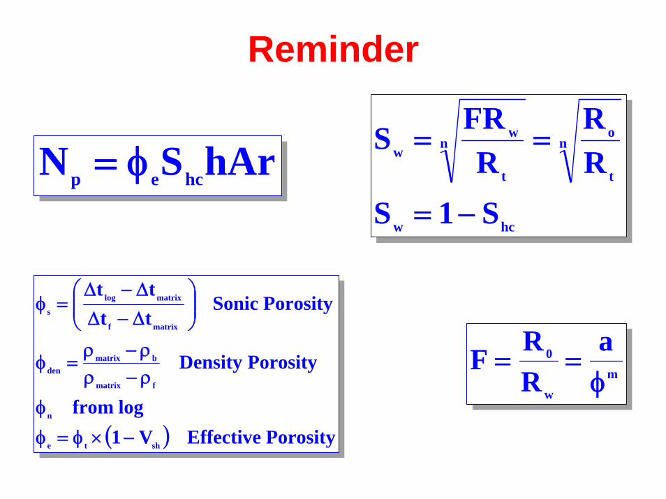
Reminder
hArSN hcep φ=hcw
n
t
on
t
ww
S1SRR
RFRS
−=
==
( ) PorosityEffectiveV1logfrom
PorosityDensity
PorositySonictttt
shte
n
fmatrix
bmatrixden
matrixf
matrixlog
s
−×φ=φφ
ρ−ρρ−ρ
=φ
⎟⎟⎠
⎞⎜⎜⎝
⎛Δ−ΔΔ−Δ
=φ
mw
0 aRRF
φ==
Reminder
• Determined Rw from the SpontaneousPotential
• Determined φt and φe from porosity and gamma ray logs
• The only parameter we lack now is thetrue resistivity of the formation

Resistivity
• The resistivity (specific resistance) of a substance is the resistance between opposite faces of a unit cube ofthat substance at a specific temperature
• Symbol R, measured in Ω·m (ohm·m2/m)
• With r = resistance in ohms; A = area in square meters; L = length in meters
• Resistivity is a basic measurement of a reservoir’s fluid saturation and is a function of porosity, type of fluid, amount of fluid and type of rock
• Usually between 0.2 and 1000 ohm·m
LArR ×
=
Resistivity
• Dependent on:– Presence of Formation water / Hydrocarbons– Salinity of Formation water– Temperature of Formation water– Volume of water-saturated pore space– Geometry of the pore space– Morphology and species of clay minerals

Tools
• Conventional Electrical logsFirst developed before 1950– Normal devices
• Short Normal (SN)• Long Normal (LN)
– Lateral devices• Laterologs (LL, e.g. LL3, LL7, LL8, LLD, LLS, SFL)
• Induction loggingFirst developed after 1950– Induction devices
• 6FF40 (combined tool: Induction, Normal and SP, 1960’s)• DIL-LL8 (improved induction-normal combination)• Induction SFL• DIL-SFL• Phasor Induction SFL• Other abbreviations: ILD, ILM, ILS, RD, RM, RS, RT

Conventional Electrical Logging
• Current of constantintensity between A and B
• Resultant potentialdifference measuredbetween M and N
• The larger the’spacing’, the deeperthe measurement
NormalDevice
LateralDevice
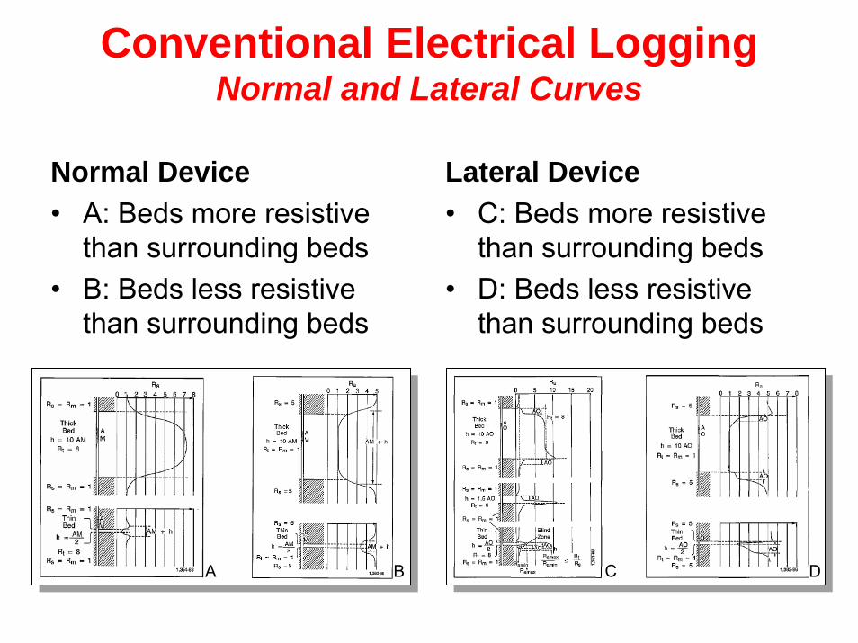
Conventional Electrical Logging Normal and Lateral Curves
Normal Device• A: Beds more resistive
than surrounding beds• B: Beds less resistive
than surrounding beds
Lateral Device• C: Beds more resistive
than surrounding beds• D: Beds less resistive
than surrounding beds
A B C D

Induction Logging
• High frequency, alternating current of constant intensity is sent through a transmitter coil (A)
• The alternating magnetic field (B) created, induces currents in the formationsurrounding the borehole (C)
• These currents flow in circular ground loops coaxial with the transitter coil and create, is turn, a magnetic field (D) that induces a current in the receiver coil (E)
AB
CD
E
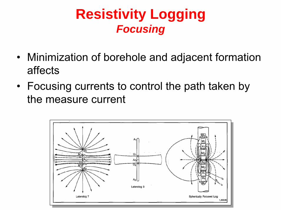
Resistivity LoggingFocusing
• Minimization of borehole and adjacent formationaffects
• Focusing currents to control the path taken by the measure current
Resistivity LoggingInfluence of well bore variables and log correction
• Resistivity measurements are influenced by:– Borehole mud– Adjacent beds– Invaded zone
• Readings must be corrected, always in thefollowing way:– Borehole effect– Adjacent bed effect– Invasion correction

Resistivity LoggingCorrections - Borehole Effect
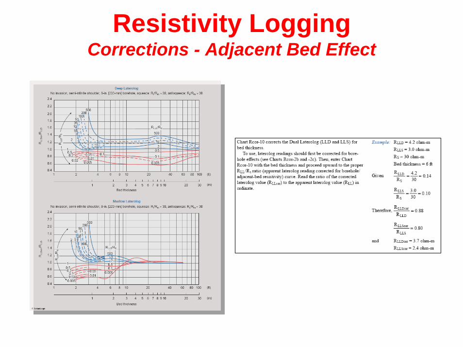
Resistivity LoggingCorrections - Adjacent Bed Effect

Resistivity LoggingInvasion Correction
’Tornado’ or ’Butterfly’ Chart
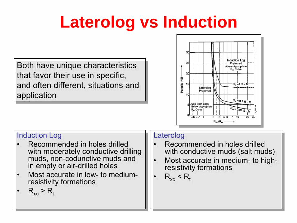
Laterolog vs Induction
Induction Log• Recommended in holes drilled
with moderately conductive drilling muds, non-codunctive muds and in empty or air-drilled holes
• Most accurate in low- to medium-resistivity formations
• Rxo > Rt
Induction Log• Recommended in holes drilled
with moderately conductive drilling muds, non-codunctive muds and in empty or air-drilled holes
• Most accurate in low- to medium-resistivity formations
• Rxo > Rt
Laterolog• Recommended in holes drilled
with conductive muds (salt muds)• Most accurate in medium- to high-
resistivity formations• Rxo < Rt
Laterolog• Recommended in holes drilled
with conductive muds (salt muds)• Most accurate in medium- to high-
resistivity formations• Rxo < Rt
Both have unique characteristicsthat favor their use in specific, and often different, situations and application
Both have unique characteristicsthat favor their use in specific, and often different, situations and application
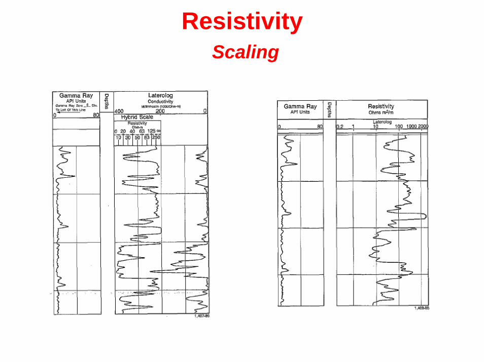
ResistivityScaling

Determination of Saturation
mw
0 aRRF
φ==n
t
ww R
FRS =
tw
w
t
ww
1a,2mn
tm
wnw
R1
SR
RRS
RaRS
=φ→
=φ→φ
====
Determination of Saturation
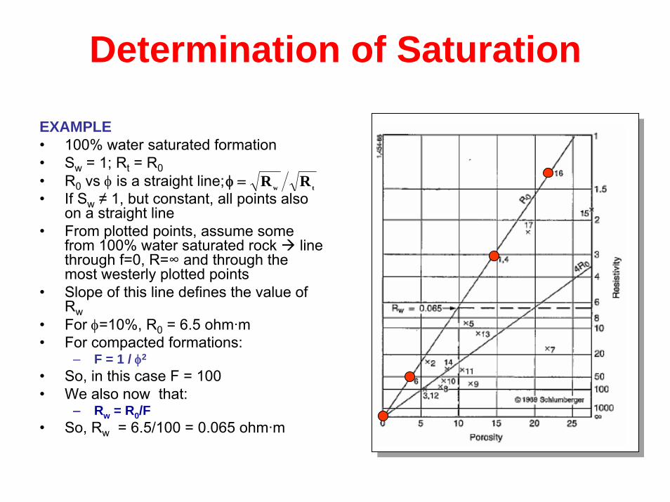
EXAMPLE• 100% water saturated formation• Sw = 1; Rt = R0• R0 vs φ is a straight line;• If Sw ≠ 1, but constant, all points also
on a straight line• From plotted points, assume some
from 100% water saturated rock line through f=0, R=∞ and through the most westerly plotted points
• Slope of this line defines the value ofRw
• For φ=10%, R0 = 6.5 ohm·m• For compacted formations:
– F = 1 / φ2
• So, in this case F = 100• We also now that:
– Rw = R0/F• So, Rw = 6.5/100 = 0.065 ohm·m
tw RR=φ

Determination of Saturation
• Only possible for formations with constant matrixand for constant Formation Water Resistivities