understanding electronics components - pole shift … : books : understanding electronic components...
TRANSCRIPT
mikroElektronika : books : Understanding electronic components
Understanding Electronic Components
IndexDevelopment systemsContact us
Previous page Table of contents Next Page
Understanding Electronics Componentson-line, FREE! author: Filipovic D. Miomir This book is meant for those people who want to create electronic devices with their own hands. All components are illustrated and the circuit-symbol is explained in detail. Both simple and complex examples are provided for the beginners. These include resistors, capacitors, transformers, transistors, integrated circuits, etc and each has its own symbol to represent it in an electrical or electronic diagram - called a circuit diagram. In order to understand how a certain device functions, it is necessary to know each symbol and the characteristics of the component. These are the things we will be covering in this book.
E-mail a friend about this item
Contents:
1. RESISTORS 1.1. Marking the resistors 1.2. Resistor power 1.3. Nonlinear resistors 1.4. Practical examples 1.5. Potentiometers 1.6. Practical examples 2. CAPACITORS 2.1. Block-capacitors 2.1.1. Marking the clock-capacitors 2.2. Electrolytic capacitors 2.3. Variable capacitors 2.4. Practical examples 3. COILS AND TRANSFORMERS 3.1. Coils 3.2. Transformers 3.2.1. Working principles and characteristics of transformers 3.3. Practical examples
6. THYRISTORS, TRIAC, DIAC 6.1. Practical examples 7. INTEGRATED CIRCUITS 7.1. Analog integrated circuits 7.2. Digital integrated circuits 7.3. Practical examples 8. MICROPHONES, SPEAKERS, HEADPHONES 8.1. Microphones 8.2. Speakers 8.3. Headphones 8.4. Practical examples 9. OPTO-ELECTRONIC COMPONENTS 9.1. Practical examples 10. OTHER COMPONENTS 10.1. Relays 10.2. Practical examples 11. COMPONENTS CHECK
http://www.mikroe.com/en/books/keu/00.htm (1 of 2)12/20/2006 4:51:08 PM
mikroElektronika : books : Understanding electronic components
4. TRANSISTORS 4.1. Working principles of transistors 4.2. Basic characteristics of transistors 4.3. The safest way to test transistors 4.4. TUN and TUP 4.5. Practical examples 5. DIODES 5.1. Marking the diodes 5.2. Characteristics of diodes 5.3. Practical examples
11.1. Diodes and transistors 11.2. Transformers and coils 11.3. Capacitors 11.4. Potentiometers 11.5. Speakers, headphones, microphones 12. CONDUCTIVITY PROBE 12.1. Semiconductors check 12.2. Other components check
To readers knowledge:
The contents published in the book "Understanding electronic components" is subject to copyright and it must not be reproduced in any form without an explicit written permission released from the editorial of mikroElektronika. The contact address for the authorization regarding contents of this book: [email protected] . The book was prepared with due care and attention, however the publisher doesn't accept any responsibility neither for the exactness of the information published therein, nor for any consequences of its application.
Send us a comment on the book "Undestanding electronic components" Subject: Comment:
Name:
E-mail:
State:
© C o p y r i g h t 2 0 0 3. m i k r o E l e k t r o n i k a. All Rights Reserved. For any comments contact webmaster.
http://www.mikroe.com/en/books/keu/00.htm (2 of 2)12/20/2006 4:51:08 PM
mikroElektronika | Solutions for the embedded systems
Home Development Tools Compilers Special Offer Easy Buy
Projects Download Books Distributors About us Contact Us
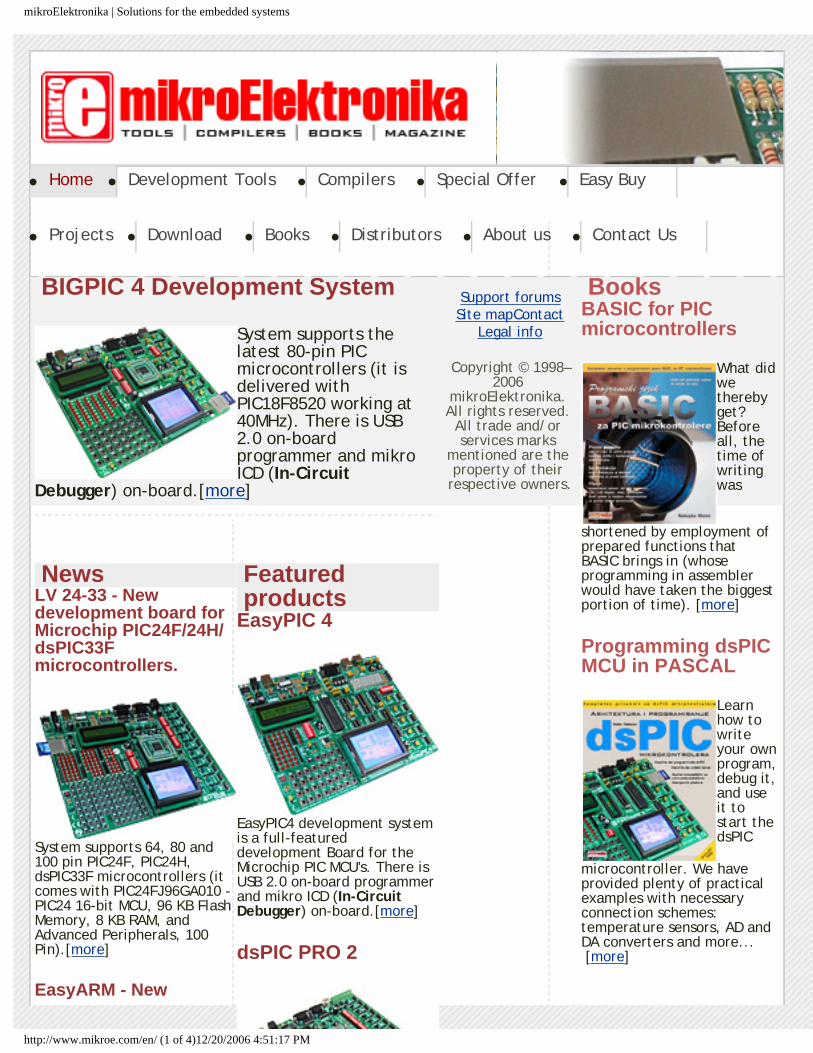
BIGPIC 4 Development System
System supports the latest 80-pin PIC microcontrollers (it is delivered with PIC18F8520 working at 40MHz). There is USB 2.0 on-board programmer and mikro ICD (In-Circuit
Debugger) on-board.[more]
NewsLV 24-33 - New development board for Microchip PIC24F/24H/dsPIC33F microcontrollers.
System supports 64, 80 and 100 pin PIC24F, PIC24H, dsPIC33F microcontrollers (it comes with PIC24FJ96GA010 - PIC24 16-bit MCU, 96 KB Flash Memory, 8 KB RAM, and Advanced Peripherals, 100 Pin).[more]
EasyARM - New
Featured products
EasyPIC 4
EasyPIC4 development system is a full-featured development Board for the Microchip PIC MCU's. There is USB 2.0 on-board programmer and mikro ICD (In-Circuit Debugger) on-board.[more]
dsPIC PRO 2
BooksBASIC for PIC microcontrollers
What did we thereby get? Before all, the time of writing was
shortened by employment of prepared functions that BASIC brings in (whose programming in assembler would have taken the biggest portion of time). [more]
Programming dsPIC MCU in PASCAL
Learn how to write your own program, debug it, and use it to start the dsPIC
microcontroller. We have provided plenty of practical examples with necessary connection schemes: temperature sensors, AD and DA converters and more... [more]
Support forumsSite mapContact
Legal info
Copyright © 1998–2006
mikroElektronika. All rights reserved.
All trade and/or services marks
mentioned are the property of their
respective owners.
http://www.mikroe.com/en/ (1 of 4)12/20/2006 4:51:17 PM
mikroElektronika | Solutions for the embedded systems
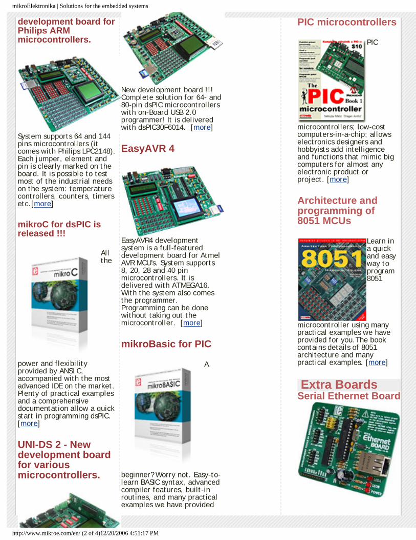
development board for Philips ARM microcontrollers.
System supports 64 and 144 pins microcontrollers (it comes with Philips LPC2148). Each jumper, element and pin is clearly marked on the board. It is possible to test most of the industrial needs on the system: temperature controllers, counters, timers etc.[more]
mikroC for dsPIC is released !!!
All the
power and flexibility provided by ANSI C, accompanied with the most advanced IDE on the market. Plenty of practical examples and a comprehensive documentation allow a quick start in programming dsPIC. [more]
UNI-DS 2 - New development board for various microcontrollers.
New development board !!! Complete solution for 64- and 80-pin dsPIC microcontrollers with on-Board USB 2.0 programmer! It is delivered with dsPIC30F6014. [more]
EasyAVR 4
EasyAVR4 development system is a full-featured development board for Atmel AVR MCU's. System supports 8, 20, 28 and 40 pin microcontrollers. It is delivered with ATMEGA16. With the system also comes the programmer. Programming can be done without taking out the microcontroller. [more]
mikroBasic for PIC
A
beginner? Worry not. Easy-to-learn BASIC syntax, advanced compiler features, built-in routines, and many practical examples we have provided
PIC microcontrollers
PIC
microcontrollers; low-cost computers-in-a-chip; allows electronics designers and hobbyists add intelligence and functions that mimic big computers for almost any electronic product or project. [more]
Architecture and programming of 8051 MCUs
Learn in a quick and easy way to program 8051
microcontroller using many practical examples we have provided for you.The book contains details of 8051 architecture and many practical examples. [more]
Extra BoardsSerial Ethernet Board
http://www.mikroe.com/en/ (2 of 4)12/20/2006 4:51:17 PM
mikroElektronika | Solutions for the embedded systems
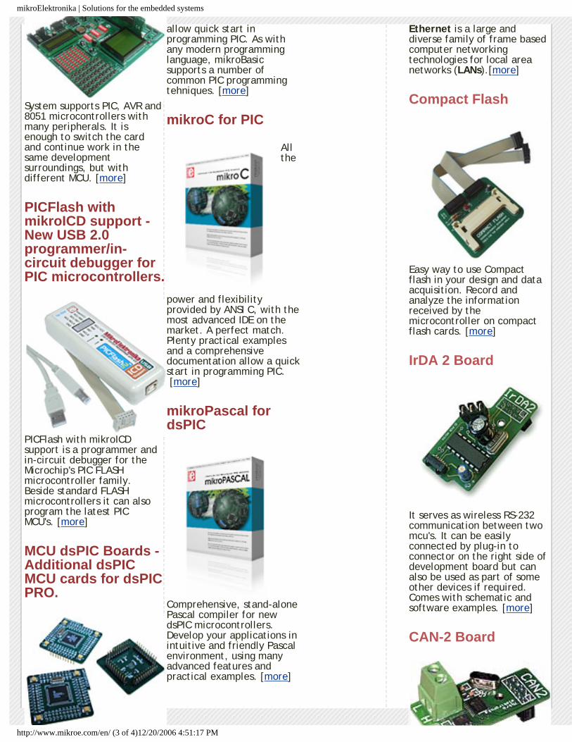
System supports PIC, AVR and 8051 microcontrollers with many peripherals. It is enough to switch the card and continue work in the same development surroundings, but with different MCU. [more]
PICFlash with mikroICD support - New USB 2.0 programmer/in-circuit debugger for PIC microcontrollers.
PICFlash with mikroICD support is a programmer and in-circuit debugger for the Microchip's PIC FLASH microcontroller family. Beside standard FLASH microcontrollers it can also program the latest PIC MCU's. [more]
MCU dsPIC Boards - Additional dsPIC MCU cards for dsPIC PRO.
allow quick start in programming PIC. As with any modern programming language, mikroBasic supports a number of common PIC programming tehniques. [more]
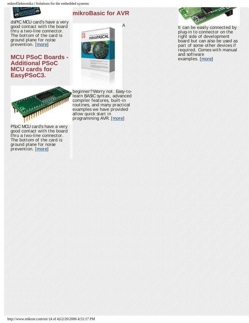
mikroC for PIC
All the
power and flexibility provided by ANSI C, with the most advanced IDE on the market. A perfect match. Plenty practical examples and a comprehensive documentation allow a quick start in programming PIC. [more]
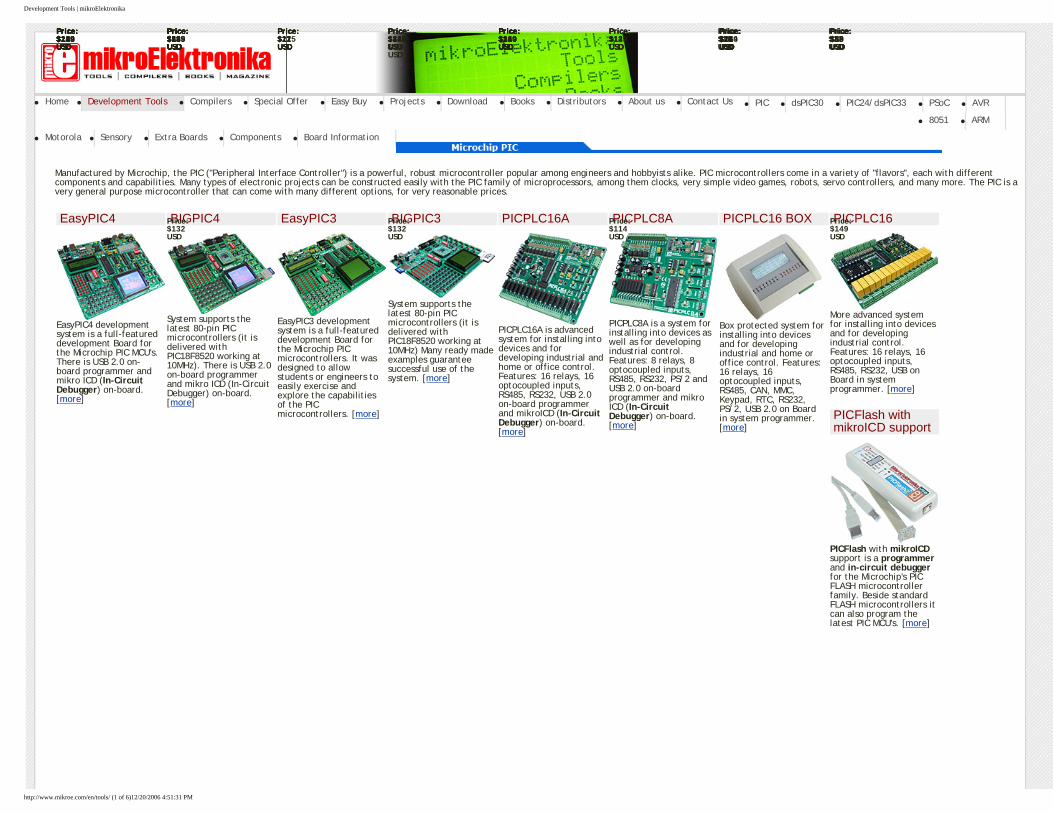
mikroPascal for dsPIC
Comprehensive, stand-alone Pascal compiler for new dsPIC microcontrollers. Develop your applications in intuitive and friendly Pascal environment, using many advanced features and practical examples. [more]
Ethernet is a large and diverse family of frame based computer networking technologies for local area networks (LANs).[more]
Compact Flash
Easy way to use Compact flash in your design and data acquisition. Record and analyze the information received by the microcontroller on compact flash cards. [more]
IrDA 2 Board
It serves as wireless RS-232 communication between two mcu's. It can be easily connected by plug-in to connector on the right side of development board but can also be used as part of some other devices if required. Comes with schematic and software examples. [more]
CAN-2 Board
http://www.mikroe.com/en/ (3 of 4)12/20/2006 4:51:17 PM
mikroElektronika | Solutions for the embedded systems
dsPIC MCU card's have a very good contact with the board thru a two-line connector. The bottom of the card is ground plane for noise prevention. [more]
MCU PSoC Boards - Additional PSoC MCU cards for EasyPSoC3.
PSoC MCU card's have a very good contact with the board thru a two-line connector. The bottom of the card is ground plane for noise prevention. [more]
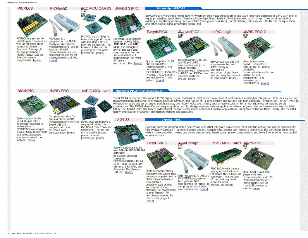
mikroBasic for AVR
A
beginner? Worry not. Easy-to-learn BASIC syntax, advanced compiler features, built-in routines, and many practical examples we have provided allow quick start in programming AVR. [more]
It can be easily connected by plug-in to connector on the right side of development board but can also be used as part of some other devices if required. Comes with manual and software examples. [more]
http://www.mikroe.com/en/ (4 of 4)12/20/2006 4:51:17 PM
Development Tools | mikroElektronika
Home Development Tools Compilers Special Offer Easy Buy Projects Download Books Distributors About us Contact Us PIC dsPIC30 PIC24/dsPIC33 PSoC AVR
8051 ARM
Motorola Sensory Extra Boards Components Board Information
Manufactured by Microchip, the PIC ("Peripheral Interface Controller") is a powerful, robust microcontroller popular among engineers and hobbyists alike. PIC microcontrollers come in a variety of "flavors", each with different components and capabilities. Many types of electronic projects can be constructed easily with the PIC family of microprocessors, among them clocks, very simple video games, robots, servo controllers, and many more. The PIC is a very general purpose microcontroller that can come with many different options, for very reasonable prices.
EasyPIC4
EasyPIC4 development system is a full-featured development Board for the Microchip PIC MCU's. There is USB 2.0 on-board programmer and mikro ICD (In-Circuit Debugger) on-board. [more]
BIGPIC4
System supports the latest 80-pin PIC microcontrollers (it is delivered with PIC18F8520 working at 10MHz). There is USB 2.0 on-board programmer and mikro ICD (In-Circuit Debugger) on-board. [more]
EasyPIC3
EasyPIC3 development system is a full-featured development Board for the Microchip PIC microcontrollers. It was designed to allow students or engineers to easily exercise and explore the capabilities of the PIC microcontrollers. [more]
BIGPIC3
System supports the latest 80-pin PIC microcontrollers (it is delivered with PIC18F8520 working at 10MHz) Many ready made examples guarantee successful use of the system. [more]
PICPLC16A
PICPLC16A is advanced system for installing into devices and for developing industrial and home or office control. Features: 16 relays, 16 optocoupled inputs, RS485, RS232, USB 2.0 on-board programmer and mikroICD (In-Circuit Debugger) on-board. [more]
PICPLC8A
PICPLC8A is a system for installing into devices as well as for developing industrial control. Features: 8 relays, 8 optocoupled inputs, RS485, RS232, PS/2 and USB 2.0 on-board programmer and mikro ICD (In-Circuit Debugger) on-board. [more]
PICPLC16 BOX
Box protected system for installing into devices and for developing industrial and home or office control. Features: 16 relays, 16 optocoupled inputs, RS485, CAN, MMC, Keypad, RTC, RS232, PS/2, USB 2.0 on Board in system programmer. [more]
PICPLC16
More advanced system for installing into devices and for developing industrial control. Features: 16 relays, 16 optocoupled inputs, RS485, RS232, USB on Board in system programmer. [more]
PICFlash with mikroICD support
PICFlash with mikroICD support is a programmer and in-circuit debugger for the Microchip's PIC FLASH microcontroller family. Beside standard FLASH microcontrollers it can also program the latest PIC MCU's. [more]
Price: $119 USD
Price: $132 USD
Price: $115 USD
Price: $132 USD
Price: $149 USD
Price: $114 USD
Price: $219 USD
Price: $149 USD
Price: $89 USD
Price: $114 USD
Price: $89 USD
Price: $149 USD
Price: $119 USD
Price: $75 USD
Price: $132 USD
Price: $239 USD
Price: $21 USD
Price: $139 USD
Price: $169 USD
Price: $18 USD
Price: $149 USD
Price: $135 USD
Price: $114 USD
Price: $149 USD
Price: $114 USD
Price: $59 USD
Price: $149 USD
Price: $149 USD
Price: $34/$36 USD
Price: $114 USD
Price: $129 USD
Price: $16 USD
Price: $18 USD
Price: $22 USD
Price: $24 USD
Price: $18 USD
Price: $17 USD
Price: $24 USD
Price: $16 USD
Price: $18 USD
Price: $28 USD
Price: $5 USD
Price: $8 USD
Price: $12 USD
Price: $8 USD
Price: $12 USD
Price: $12 USD
Price: $12 USD
Price: $8 USD
http://www.mikroe.com/en/tools/ (1 of 6)12/20/2006 4:51:31 PM
Development Tools | mikroElektronika
PICPLC8
PICPLC8 is a system for installing into devices as well as for developing industrial control. Features: 8 relays, 8 optocoupled inputs, RS485, RS232, USB on Board in system programmer. [more]
PICFlash2
PICFlash2 is a programmer for FLASH family of Microchip's microcontrollers. Beside standard FLASH microcontrollers it can also program the latest microcontrollers of PIC. [more]
PIC MCU CARDS
PIC MCU card's (80 pin) have a very good contact with the Board thru a two-line connector. The bottom of the card is ground plane for noise prevention. [more]
UNI-DS 3 [PIC]
Universal Development system for PIC, PSOC, AVR, 8051 and ARM MCU. It is enough to switch the card and continue work in the same development surroundings, but with different microcontroller. [more]
dsPIC30Fs are Microchip's newer family, which entered mass production in late 2004. They are designed as a PIC with digital signal processing capabilities. These are Microchip's first inherent 16-bit (data) microcontrollers. They build on the PICs existing strengths by offering hardware MAC (multiply-accumulate), barrel shifting, bit reversal, (16x16)-bit multiplication and other digital signal processing operations.
EasydsPIC3
System supports 18, 28, and 40-pin dsPIC microcontrollers (it is delivered with dsPIC30F4013). Examples in BASIC, PASCAL and C are included with the system. [more]
EasydsPIC2
System supports 18, 28, and 40-pin dsPIC microcontrollers (it is delivered with dsPIC30F4013). Examples in BASIC and PASCAL are included with the system. [more]
dsPICprog2
dsPICprog2 is a USB 2.0 programmer for new dsPIC family of Microchip's microcontrollers. Very fast and easy to connect on your Board. [more]
dsPIC PRO 2
New development board !!! Complete solution for 64- and 80-pin dsPIC microcontrollers with on-Board USB 2.0 programmer! It is delivered with dsPIC30F6014. [more]
BIGdsPIC
System supports the latest 80-pin dsPIC microcontrollers (it is delivered with PIC30F6014 working at 10MHz) Many ready made examples guarantee successful use of the system. [more]
dsPIC PRO
Complete solution for 64- and 80-pin dsPIC microcontrollers with on-Board USB 2.0 programmer! It is delivered with dsPIC30F6014. [more]
dsPIC MCU card
dsPIC MCU card's have a very good contact with the Board thru a two-line connector. The bottom of the card is ground plane for noise prevention. [more]
16-bit PIC24 microcontrollers and dsPIC33 Digital Signal Controllers (DSC) offer a new level of performance and higher integration. Features supporting this compatibility between these families include common: Instruction set & architecture (dsPIC DSCs add DSP capability), Peripherals, Pin-out. With 16 MIPS performance and an extensive peripheral set, the PIC24F MCUs are a highly cost-effective solution for all but the most demanding 16-bit applications. The PIC24F also offers an easy migration path for design engineers whose applications have outgrown the performance offered by 8-bit MCUs. The 40 MIPS dsPIC33F family is developed for high performance embedded control applications. Compared to the dsPIC30F family, the dsPIC33F family offers larger RAM and Flash memory options and adds DMA.
LV 24-33
System supports 64, 80 and 100 pin PIC24F/24H/dsPIC33F microcontrollers (it comes with PIC24FJ96GA010 - PIC24 16-bit MCU, 96 KB Flash Memory, 8 KB RAM, and Advanced Peripherals, 100 Pin). [more]
Cypress PSoC's are programmable systems-on-chips that integrate a microcontroller and the analog and digital components that typically surround it in an embedded system. A single PSoC device can integrate as many as 100 peripheral functions with a microcontroller, saving customers design time, Board space, power consumption, and from 5 cents to as much as $10 in system costs.
EasyPSoC3
PSoC microcontrollers represent the whole new concept compared to the older microcontrollers, they contain programmable analog and digital blocks, allowing the programmer to pick himself the peripherals needed for the current project. [more]
PSoCprog2
USB PSoCprog2 is USB 2.0 IN-SYSTEM programmer for Cypress PSoC microcontroller family. It can program all of PSoC microcontrollers. [more]
PSoC MCU Cards
PSoC MCU card's have a very good contact with the Board thru a two-line connector. The bottom of the card is ground plane for noise prevention. [more]
mikroPSoC
Small Credit Card size Board with PsoC microcontroller and USB PSoC programmer on it. Power supply can be from USB or external source. [more]
Price: $19/$22 USD
Price: $119 USD
Price: $239 USD
Price: $75 USD
Price: $89 USD
http://www.mikroe.com/en/tools/ (2 of 6)12/20/2006 4:51:31 PM
Development Tools | mikroElektronika
UNI-DS 3 [PSoC]
Universal Development system for PIC, PSOC, AVR, 8051 and ARM MCU. It is enough to switch the card and continue work in the same development surroundings, but with different microcontroller. [more]
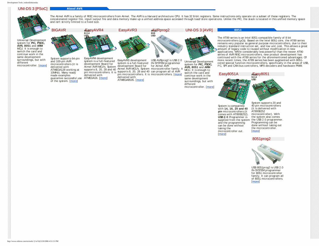
The Atmel AVR is a family of RISC microcontrollers from Atmel. The AVR is a Harvard architecture CPU. It has 32 8-bit registers. Some instructions only operate on a subset of these registers. The concatenated register file, input/output file and data memory make up a unified address space accessed through load/store operations. Unlike the PIC, the stack is located in this unified memory space and isn't strictly limited to a fixed size.
BIGAVR
System supports 64-pin and 100-pin AVR microcontrollers (it is delivered with ATMEGA128 working at 10MHz). Many ready made examples guarantee successful use of the system. [more]
EasyAVR4
EasyAVR4 development system is a full-featured development Board for Atmel AVR MCU's. System supports 8, 20, 28 and 40 pin microcontrollers. It is delivered with ATMEGA16. [more]
EasyAVR3
EasyAVR3 development system is a full-featured development Board for Atmel AVR MCU's. System supports 8, 20, 28 and 40 pin microcontrollers. It is delivered with ATMEGA8535. [more]
AVRprog2
USB AVRprog2 is USB 2.0 IN-SYSTEM programmer for Atmel AVR microcontroller family. It can program all of AVR microcontrollers. [more]
UNI-DS 3 [AVR]
Universal Development system for PIC, PSOC, AVR, 8051 and ARM MCU. It is enough to switch the card and continue work in the same development surroundings, but with different microcontroller. [more]
The AT89 series is an Intel 8051-compatible family of 8 bit microcontrollers (µCs). Based on the Intel 8051 core, the AT89 series remains very popular as general purpose microcontrollers, due to their industry standard instruction set, and low unit cost. This allows a great amount of legacy code to reused without modification in new applications. While considerably less powerful than the newer AT90 series of AVR RISC microcontrollers, new product development has continued with the AT89 series for the aforementioned advantages. Of more recent times, the AT89 series has been augmented with 8051-cored special function microcontrollers, specifically in the areas of USB, I²C, SPI and CAN bus controllers, MP3 decoders and hardware PWM.
Easy8051A
System is compatible with 14, 16, 20 and 40 pin microcontrollers (it comes with AT89S8252). USB 2.0 Programmer is supplied from the system and the programming can be done without taking the microcontroller out. [more]
Easy8051
System supports 20 and 40 pin microcontrollers (it is delivered with AT89S8252 microcontroller). With the system also comes the USB 2.0 programmer. Programming can be done without taking out the microcontroller. [more]
8051prog2
USB 8051prog2 is USB 2.0 IN-SYSTEM programmer for 8051 microcontroller family. It can program all of 8051 microcontrollers. [more]
Price: $114 USD
Price: $59 USD
Price: $114 USD
http://www.mikroe.com/en/tools/ (3 of 6)12/20/2006 4:51:31 PM
Development Tools | mikroElektronika
UNI-DS 3 [8051]
Universal Development system for PIC, PSOC, AVR, 8051 and ARM MCU. It is enough to switch the card and continue work in the same development surroundings, but with different microcontroller. [more]
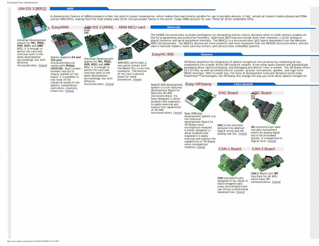
A characteristic feature of ARM processors is their low electric power consumption, which makes them particularly suitable for use in portable devices. In fact, almost all modern mobile phones and PDAs contain ARM CPU's, making them the most widely-used 32-bit microprocessor family in the world. Today ARM's account for over 75% of all 32-bit embedded CPUs..
EasyARM
System supports 64 and 144 pins microcontrollers (it comes with Philips LPC2148). Each jumper, element and pin is clearly marked on the board. It is possible to test most of the industrial needs on the system: temperature controllers, counters, timers etc. [more]
UNI-DS 3 [ARM]
Universal Development system for PIC, PSOC, AVR, 8051 and ARM MCU. It is enough to switch the card and continue work in the same development surroundings, but with different microcontroller. [more]
ARM MCU card
ARM MCU card's have a very good contact with the Board thru a two-line connector. The bottom of the card is ground plane for noise prevention. [more]
The HC908 microcontroller provides intelligence for demanding motion control decisions while its flash memory enables on-the-fly programming and production flexibility. Additional MCU features include dual timer channels, a 10-bit analog-to-digital converter and serial peripheral interface. The 68HC11 is a microcontroller (µC) family descended from the Motorola 6800 microprocessor. The 68HC11 devices are more powerful and more expensive than the 68HC05 microcontrollers, and are used in barcode readers, hotel card key writers, and various other embedded systems.
EasyHC-908
EasyHC-908 development system is a full-featured development Board for Motorola HC-908 microcontrollers. It's been designed to allow students and engineers to easily exercise and explore the capabilities of HC-908 microcontrollers. [more]
VR Stamp simplifies the integration of speech recognition into products by combining all key components into a small 40-pin DIP footprint module. A low-noise audio channel and standardized packaging allow rapid prototyping, less debugging and shorter time to market. The VR Stamp offers 24 I/O lines, as well as connections for a power, ground, microphone, speaker, and logic-level RS232 interface. With its small size, full suite of development tools and Sensory's world-class FluentChip™ Technologies, the VR Stamp will change the way you think about speech recognition.
Easy-VRStamp
Easy-VRStamp development system is a full-featured development Board for VR Stamp voice recongnition modules. It's been designed to allow students and engineers to easily exercise and explore the capabilities of VR Stamp voice recongnition modules. [more]
DAC Board
DAC is the interface between the abstract digital world and the analog real life. [more]
ADC Board
AD converters are used virtually everywhere where an analog signal has to be processed, stored, or transported in digital form. [more]
CAN-1 Board
CAN was specifically designed to be robust in electromagnetically noisy environments and can utilize a differential balanced line. [more]
CAN-2 Board
CAN 2 Board with SPI interface for all MCU which have SPI communication. [more]
Price: $149 USD
Price: $22 USD
http://www.mikroe.com/en/tools/ (4 of 6)12/20/2006 4:51:31 PM
Development Tools | mikroElektronika
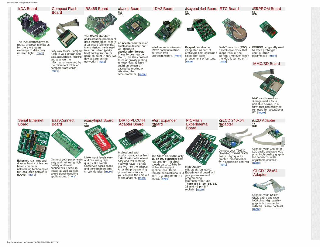
IrDA Board
The IrDA defines physical specs. protocol standards for the short range exchange of data over infrared light. [more]
Compact Flash Board
Easy way to use Compact flash in your design and data acquisition. Record and analyze the information received by the microcontroller on compact flash cards. [more]
RS485 Board
The RS485 standard addresses the problem of data transmission, where a balanced (differential) transmission line is used in a multi-drop (party line) configuration (or point-to-point if only two devices are on the network). [more]
Accel. Board
An Accelerometer is an electronic device that will measure acceleration forces. These forces may be static, like the constant force of gravity pulling at your feet, or they could be dynamic - caused by moving or vibrating the accelerometer. [more]
IrDA2 Board
Irda2 serve as wireless RS232 communication between two Microcontrollers. [more]
Keypad 4x4 Board
Keypad can also be integrated as part of prototype that contains a calculator-style arrangement of buttons. [more]
RTC Board
Real-Time clock (RTC) is a electronic clock that keeps track of the current time even when the MCU is turned off. [more]
EEPROM Board
EEPROM is typically used to store prototype configuration parameters. [more]
MMC/SD Board
MMC card is used as storage media for a portable device, in a form that can easily be removed for access by a PC. [more]
Serial Ethernet Board
Ethernet is a large and diverse family of frame-based computer networking technologies for local area networks (LANs). [more]
EasyConnect Board
Connect your peripherals easy and fast using high quality on-board connectors. Useful in power as well as high-speed signal-handling applications. [more]
EasyInput Board
Make input levels easy and fast using high quality DIP switch. Conserves board space and permits increased circuit density. [more]
DIP to PLCC44 Adapter Board
Professional and production adapter from mikroElektronika allows easy and fast working. You will have to press the PIC into the adapter. After the programming procedure is finished, you can pull the chip out of the adapter. [more]
Port Expander Board
The MCP23S17 is the only 16-bit I/O expander that features SPI(tm) clock speeds up to 10 MHz for higher throughput applications. 16-bit remote bi-directional I/O port (I/O pins default to input). [more]
PICFlash Experimental Board
High Quality mikroElektronika PIC Experimental board will give you easiness of programming microcontroller unit. There are 8, 10, 14, 18, 28 and 40 pin DIP sockets. [more]
GLCD 240x64 Adapter
Connect your T6963C (Toshiba) 240x64 GLCD easily. High quality graphic lcd connector with adjustable contrast. [more]
LCD Adapter
Connect your Character LCD easily and save MCU pins. High quality graphic lcd connector with adjustable contrast. [more]
GLCD 128x64 Adapter
Connect your 128x64 GLCD easily and save MCU pins. High quality graphic lcd connector with adjustable contrast. [more]
Price: $19 USD
Price: $9 USD
Price: $8 USD
Price: $5 USD
Price: $12 USD
Price: $8 USD
Price: $8 USD
http://www.mikroe.com/en/tools/ (5 of 6)12/20/2006 4:51:31 PM
Development Tools | mikroElektronika
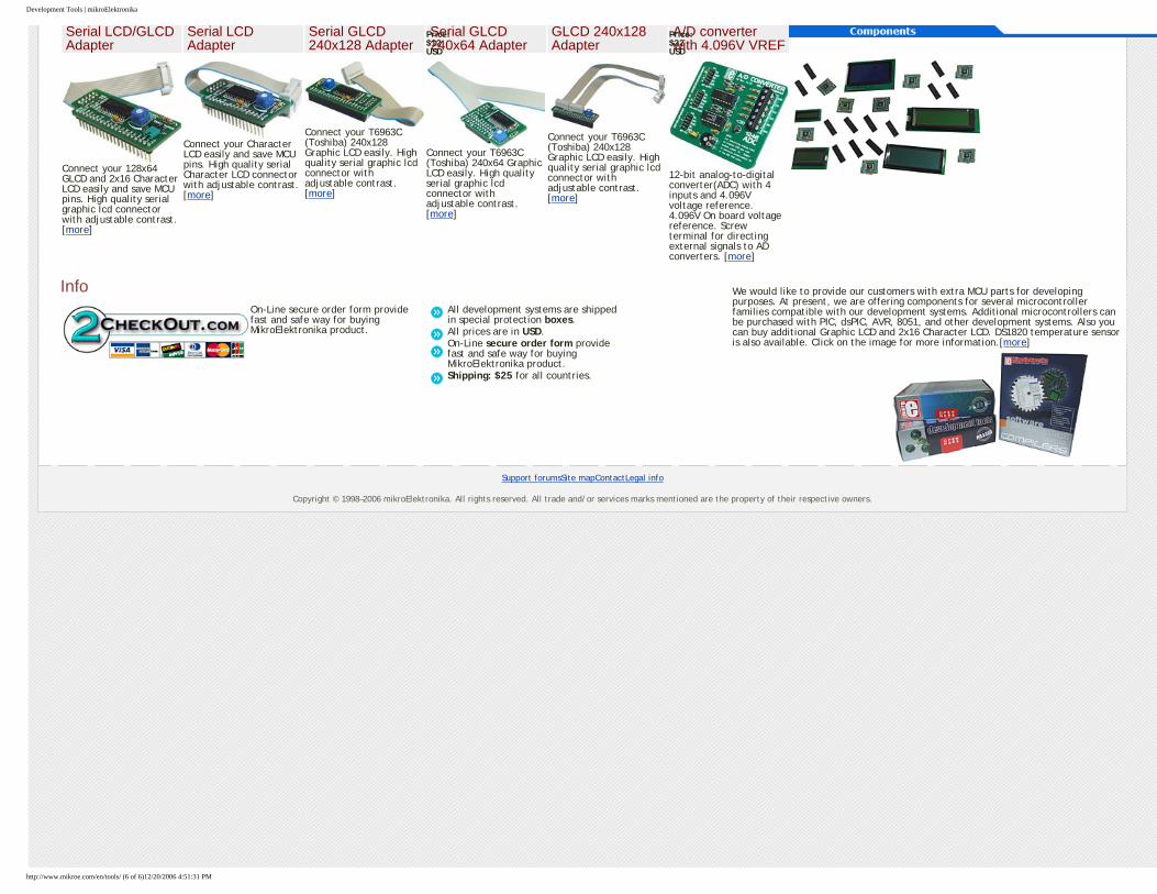
Serial LCD/GLCD Adapter
Connect your 128x64 GLCD and 2x16 Character LCD easily and save MCU pins. High quality serial graphic lcd connector with adjustable contrast. [more]
Serial LCD Adapter
Connect your Character LCD easily and save MCU pins. High quality serial Character LCD connector with adjustable contrast. [more]
Serial GLCD 240x128 Adapter
Connect your T6963C (Toshiba) 240x128 Graphic LCD easily. High quality serial graphic lcd connector with adjustable contrast. [more]
Serial GLCD 240x64 Adapter
Connect your T6963C (Toshiba) 240x64 Graphic LCD easily. High quality serial graphic lcd connector with adjustable contrast. [more]
GLCD 240x128 Adapter
Connect your T6963C (Toshiba) 240x128 Graphic LCD easily. High quality serial graphic lcd connector with adjustable contrast. [more]
A/D converter with 4.096V VREF
12-bit analog-to-digital converter(ADC) with 4 inputs and 4.096V voltage reference. 4.096V On board voltage reference. Screw terminal for directing external signals to AD converters. [more]
We would like to provide our customers with extra MCU parts for developing purposes. At present, we are offering components for several microcontroller families compatible with our development systems. Additional microcontrollers can be purchased with PIC, dsPIC, AVR, 8051, and other development systems. Also you can buy additional Graphic LCD and 2x16 Character LCD. DS1820 temperature sensor is also available. Click on the image for more information.[more]
InfoOn-Line secure order form provide fast and safe way for buying MikroElektronika product.
All development systems are shipped in special protection boxes.All prices are in USD.On-Line secure order form provide fast and safe way for buying MikroElektronika product.Shipping: $25 for all countries.
Support forumsSite mapContactLegal info
Copyright © 1998–2006 mikroElektronika. All rights reserved. All trade and/or services marks mentioned are the property of their respective owners.
Price: $12 USD
Price: $22 USD
http://www.mikroe.com/en/tools/ (6 of 6)12/20/2006 4:51:31 PM

Contact | mikroElektronika
Home Development Tools Compilers Special Offer Easy Buy
Projects Download Books Distributors About us Contact Us
Contact usIf you are experiencing trouble with any of our products or you just need additional information, please let us know — we are committed to meeting your every need.
The preferred method of contacting mikroElektronika is via e-mail. We recommend that you use the form below to ensure a prioritized response.
Contact Form
Fill out the form and send us your message. Fields marked with an asterisk (*) are required. Don’t forget to choose the most appropriate subject for your message.
Subject
Name *
E-mail *
Company
Country
Contact off-linemikroElektronika Admirala Geprata 1B 11000 Belgrade Europe Phone: + 381 11 30 66 377 + 381 11 30 66 378 Fax: + 381 11 30 66 379 E-mail: [email protected]
Interested in distribution?
Would you like to become our distributor? Here in mikroElektronika we are looking forward to new partnerships. If you would like to help us by becoming a distributor of our products, please use the following link:
E-mail us “About Product Distribution”
If you have any other question, comment, or a business proposal, give us a call or use the contact form.
Support forumsSite mapContactLegal info
Copyright © 1998–2006 mikroElektronika. All rights reserved. All
trade and/or services marks mentioned are the property of their respective owners.
http://www.mikroe.com/en/contact/ (1 of 2)12/20/2006 4:51:33 PM

Contact | mikroElektronika
Your message *
Send me a copy of e-mail
http://www.mikroe.com/en/contact/ (2 of 2)12/20/2006 4:51:33 PM
Resistors
Understanding Electronic Components
IndexDevelopment systemsContact us
Previous page Table of contents Next page
1. Resistors
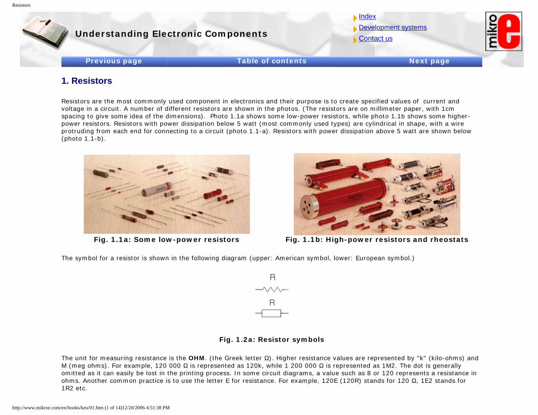
Resistors are the most commonly used component in electronics and their purpose is to create specified values of current and voltage in a circuit. A number of different resistors are shown in the photos. (The resistors are on millimeter paper, with 1cm spacing to give some idea of the dimensions). Photo 1.1a shows some low-power resistors, while photo 1.1b shows some higher-power resistors. Resistors with power dissipation below 5 watt (most commonly used types) are cylindrical in shape, with a wire protruding from each end for connecting to a circuit (photo 1.1-a). Resistors with power dissipation above 5 watt are shown below (photo 1.1-b).
Fig. 1.1a: Some low-power resistors Fig. 1.1b: High-power resistors and rheostats
The symbol for a resistor is shown in the following diagram (upper: American symbol, lower: European symbol.)
Fig. 1.2a: Resistor symbols
The unit for measuring resistance is the OHM. (the Greek letter Ω). Higher resistance values are represented by "k" (kilo-ohms) and M (meg ohms). For example, 120 000 Ω is represented as 120k, while 1 200 000 Ω is represented as 1M2. The dot is generally omitted as it can easily be lost in the printing process. In some circuit diagrams, a value such as 8 or 120 represents a resistance in ohms. Another common practice is to use the letter E for resistance. For example, 120E (120R) stands for 120 Ω, 1E2 stands for 1R2 etc.
http://www.mikroe.com/en/books/keu/01.htm (1 of 14)12/20/2006 4:51:38 PM
Resistors
1.1 Resistor Markings
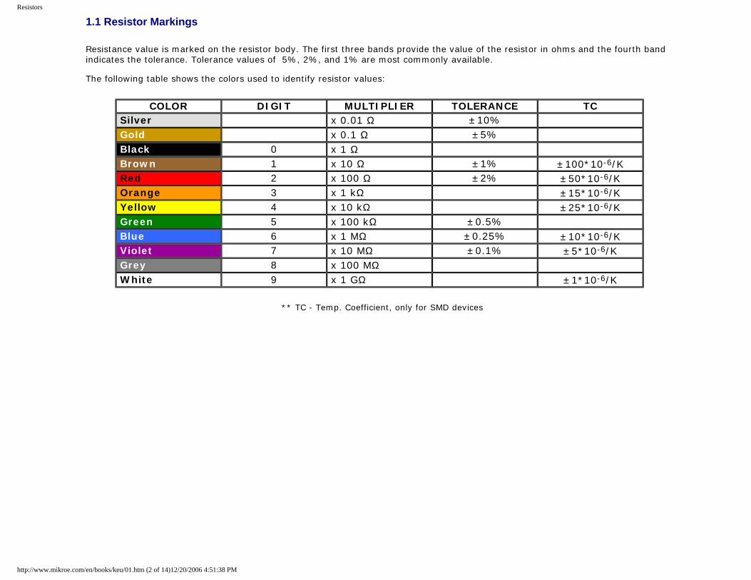
Resistance value is marked on the resistor body. The first three bands provide the value of the resistor in ohms and the fourth band indicates the tolerance. Tolerance values of 5%, 2%, and 1% are most commonly available. The following table shows the colors used to identify resistor values:
COLOR DIGIT MULTIPLIER TOLERANCE TC Silver x 0.01 Ω ±10% Gold x 0.1 Ω ±5% Black 0 x 1 Ω Brown 1 x 10 Ω ±1% ±100*10-6/K Red 2 x 100 Ω ±2% ±50*10-6/K Orange 3 x 1 kΩ ±15*10-6/K Yellow 4 x 10 kΩ ±25*10-6/K Green 5 x 100 kΩ ±0.5% Blue 6 x 1 MΩ ±0.25% ±10*10-6/K Violet 7 x 10 MΩ ±0.1% ±5*10-6/K Grey 8 x 100 MΩ White 9 x 1 GΩ ±1*10-6/K
** TC - Temp. Coefficient, only for SMD devices
http://www.mikroe.com/en/books/keu/01.htm (2 of 14)12/20/2006 4:51:38 PM
Resistors
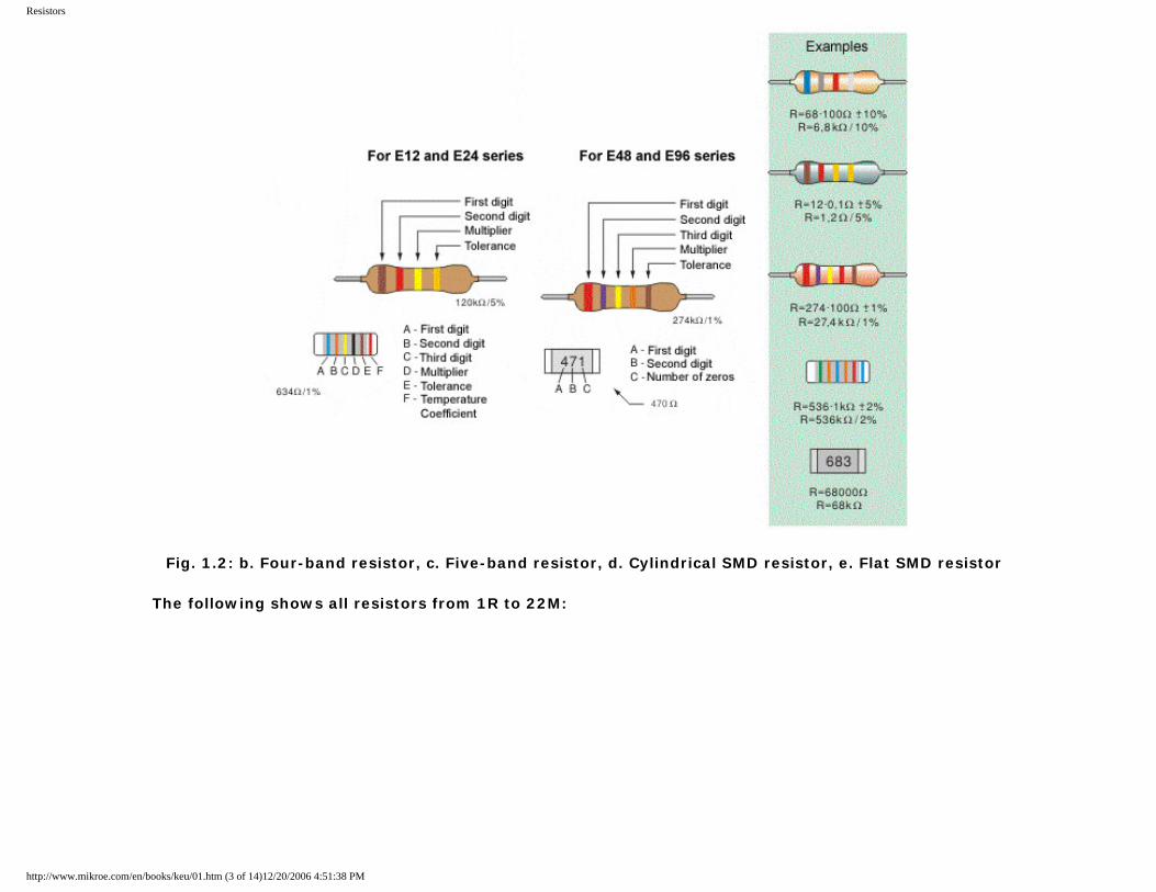
Fig. 1.2: b. Four-band resistor, c. Five-band resistor, d. Cylindrical SMD resistor, e. Flat SMD resistor
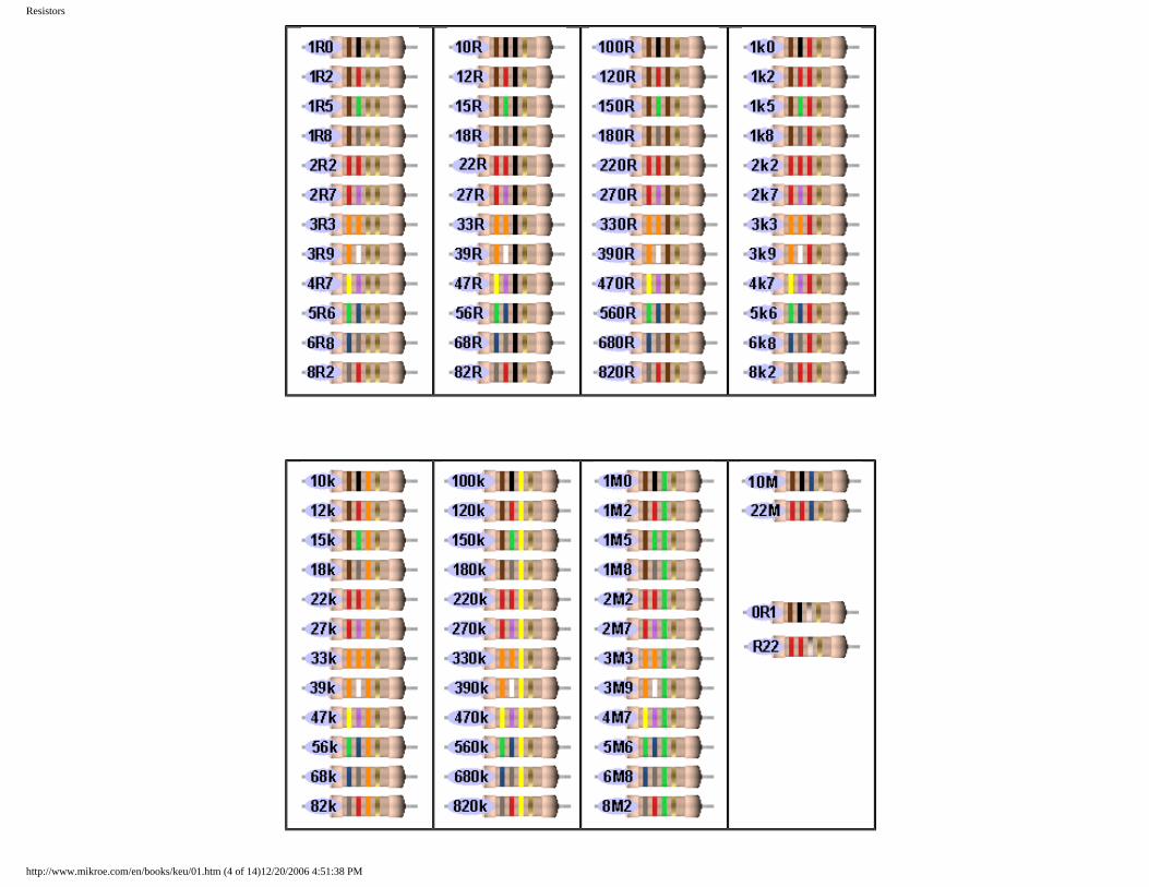
The following shows all resistors from 1R to 22M:
http://www.mikroe.com/en/books/keu/01.htm (3 of 14)12/20/2006 4:51:38 PM
Resistors
http://www.mikroe.com/en/books/keu/01.htm (4 of 14)12/20/2006 4:51:38 PM
Resistors
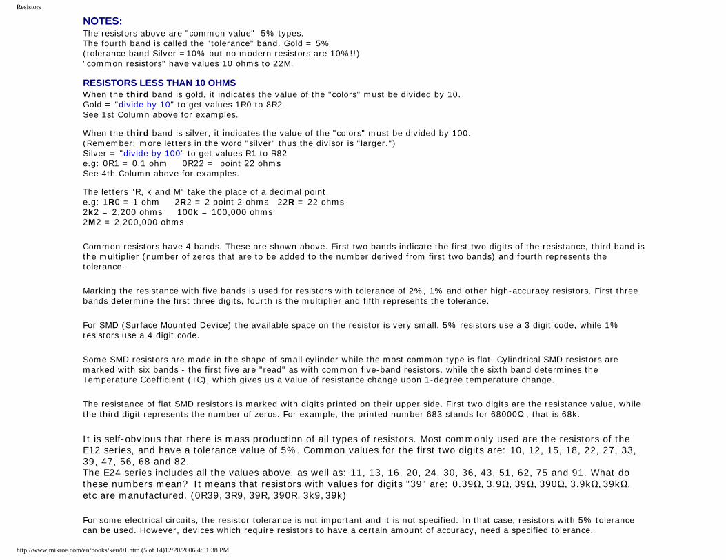
NOTES: The resistors above are "common value" 5% types. The fourth band is called the "tolerance" band. Gold = 5% (tolerance band Silver =10% but no modern resistors are 10%!!) "common resistors" have values 10 ohms to 22M. RESISTORS LESS THAN 10 OHMS When the third band is gold, it indicates the value of the "colors" must be divided by 10. Gold = "divide by 10" to get values 1R0 to 8R2 See 1st Column above for examples. When the third band is silver, it indicates the value of the "colors" must be divided by 100. (Remember: more letters in the word "silver" thus the divisor is "larger.") Silver = "divide by 100" to get values R1 to R82 e.g: 0R1 = 0.1 ohm 0R22 = point 22 ohms See 4th Column above for examples. The letters "R, k and M" take the place of a decimal point. e.g: 1R0 = 1 ohm 2R2 = 2 point 2 ohms 22R = 22 ohms 2k2 = 2,200 ohms 100k = 100,000 ohms 2M2 = 2,200,000 ohms
Common resistors have 4 bands. These are shown above. First two bands indicate the first two digits of the resistance, third band is the multiplier (number of zeros that are to be added to the number derived from first two bands) and fourth represents the tolerance.
Marking the resistance with five bands is used for resistors with tolerance of 2%, 1% and other high-accuracy resistors. First three bands determine the first three digits, fourth is the multiplier and fifth represents the tolerance.
For SMD (Surface Mounted Device) the available space on the resistor is very small. 5% resistors use a 3 digit code, while 1% resistors use a 4 digit code.
Some SMD resistors are made in the shape of small cylinder while the most common type is flat. Cylindrical SMD resistors are marked with six bands - the first five are "read" as with common five-band resistors, while the sixth band determines the Temperature Coefficient (TC), which gives us a value of resistance change upon 1-degree temperature change.
The resistance of flat SMD resistors is marked with digits printed on their upper side. First two digits are the resistance value, while the third digit represents the number of zeros. For example, the printed number 683 stands for 68000Ω , that is 68k.
It is self-obvious that there is mass production of all types of resistors. Most commonly used are the resistors of the E12 series, and have a tolerance value of 5%. Common values for the first two digits are: 10, 12, 15, 18, 22, 27, 33, 39, 47, 56, 68 and 82. The E24 series includes all the values above, as well as: 11, 13, 16, 20, 24, 30, 36, 43, 51, 62, 75 and 91. What do these numbers mean? It means that resistors with values for digits "39" are: 0.39Ω, 3.9Ω, 39Ω, 390Ω, 3.9kΩ, 39kΩ, etc are manufactured. (0R39, 3R9, 39R, 390R, 3k9, 39k)
For some electrical circuits, the resistor tolerance is not important and it is not specified. In that case, resistors with 5% tolerance can be used. However, devices which require resistors to have a certain amount of accuracy, need a specified tolerance.
http://www.mikroe.com/en/books/keu/01.htm (5 of 14)12/20/2006 4:51:38 PM
Resistors
1.2 Resistor Dissipation
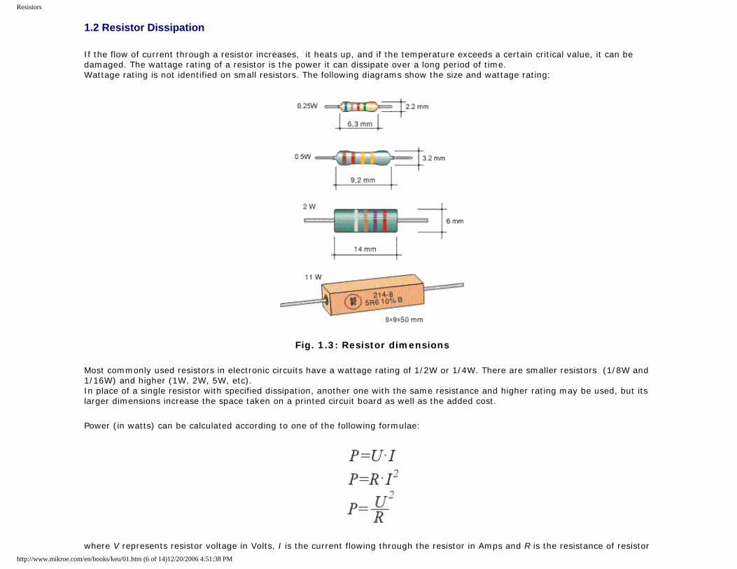
If the flow of current through a resistor increases, it heats up, and if the temperature exceeds a certain critical value, it can be damaged. The wattage rating of a resistor is the power it can dissipate over a long period of time. Wattage rating is not identified on small resistors. The following diagrams show the size and wattage rating:
Fig. 1.3: Resistor dimensions
Most commonly used resistors in electronic circuits have a wattage rating of 1/2W or 1/4W. There are smaller resistors (1/8W and 1/16W) and higher (1W, 2W, 5W, etc). In place of a single resistor with specified dissipation, another one with the same resistance and higher rating may be used, but its larger dimensions increase the space taken on a printed circuit board as well as the added cost.
Power (in watts) can be calculated according to one of the following formulae:
where V represents resistor voltage in Volts, I is the current flowing through the resistor in Amps and R is the resistance of resistor http://www.mikroe.com/en/books/keu/01.htm (6 of 14)12/20/2006 4:51:38 PM
Resistors
in Ohms. For example, if the voltage across an 820Ω resistor is 12V, the wattage dissipated by the resistors is:
A 1/4W resistor can be used.
In many cases, it is not easy to determine the current or voltage across a resistor. In this case the wattage dissipated by the resistor is determined for the "worst" case. We should assume the highest possible voltage across a resistor, i.e. the full voltage of the power supply (battery, etc). If we mark this voltage as VB, the lowest dissipation is:
For example, if VB=9V, the dissipation of a 220Ω resistor is:
A 0.5W or higher wattage resistor should be used
1.3 Nonlinear resistors
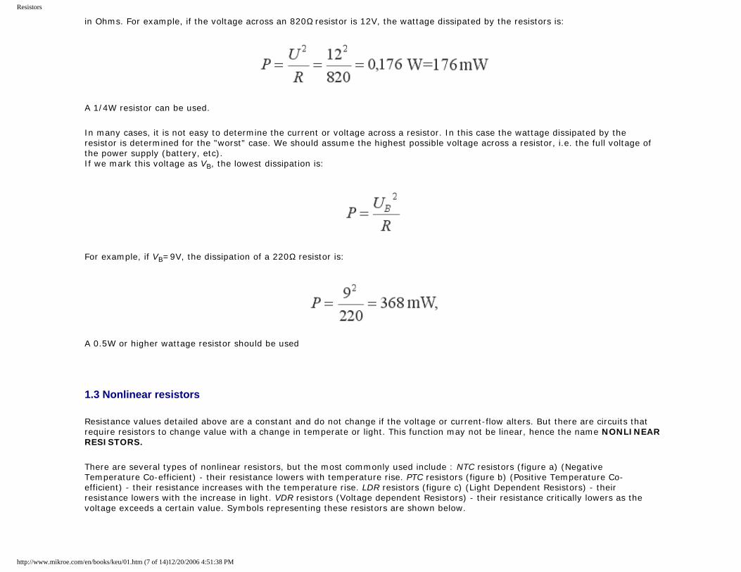
Resistance values detailed above are a constant and do not change if the voltage or current-flow alters. But there are circuits that require resistors to change value with a change in temperate or light. This function may not be linear, hence the name NONLINEAR RESISTORS.
There are several types of nonlinear resistors, but the most commonly used include : NTC resistors (figure a) (Negative Temperature Co-efficient) - their resistance lowers with temperature rise. PTC resistors (figure b) (Positive Temperature Co-efficient) - their resistance increases with the temperature rise. LDR resistors (figure c) (Light Dependent Resistors) - their resistance lowers with the increase in light. VDR resistors (Voltage dependent Resistors) - their resistance critically lowers as the voltage exceeds a certain value. Symbols representing these resistors are shown below.
http://www.mikroe.com/en/books/keu/01.htm (7 of 14)12/20/2006 4:51:38 PM
Resistors
Fig. 1.4: Nonlinear resistors - a. NTC, b. PTC, c. LDR
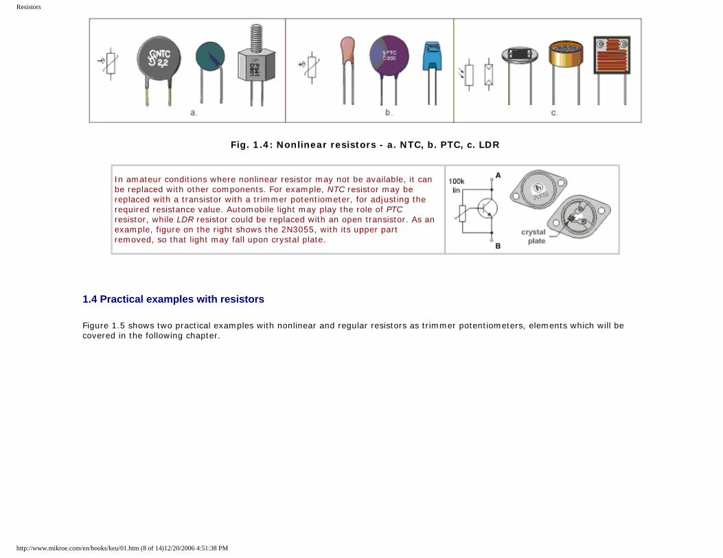
In amateur conditions where nonlinear resistor may not be available, it can be replaced with other components. For example, NTC resistor may be replaced with a transistor with a trimmer potentiometer, for adjusting the required resistance value. Automobile light may play the role of PTC resistor, while LDR resistor could be replaced with an open transistor. As an example, figure on the right shows the 2N3055, with its upper part removed, so that light may fall upon crystal plate.
1.4 Practical examples with resistors
Figure 1.5 shows two practical examples with nonlinear and regular resistors as trimmer potentiometers, elements which will be covered in the following chapter.
http://www.mikroe.com/en/books/keu/01.htm (8 of 14)12/20/2006 4:51:38 PM
Resistors
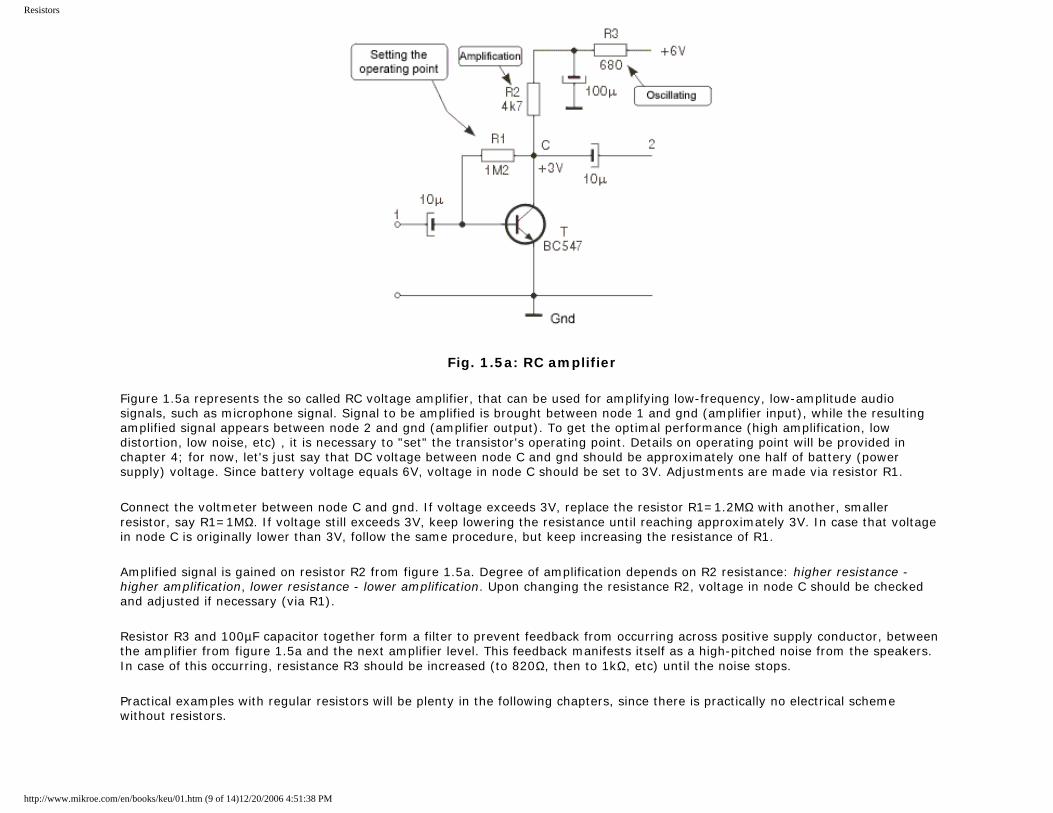
Fig. 1.5a: RC amplifier
Figure 1.5a represents the so called RC voltage amplifier, that can be used for amplifying low-frequency, low-amplitude audio signals, such as microphone signal. Signal to be amplified is brought between node 1 and gnd (amplifier input), while the resulting amplified signal appears between node 2 and gnd (amplifier output). To get the optimal performance (high amplification, low distortion, low noise, etc) , it is necessary to "set" the transistor's operating point. Details on operating point will be provided in chapter 4; for now, let's just say that DC voltage between node C and gnd should be approximately one half of battery (power supply) voltage. Since battery voltage equals 6V, voltage in node C should be set to 3V. Adjustments are made via resistor R1.
Connect the voltmeter between node C and gnd. If voltage exceeds 3V, replace the resistor R1=1.2MΩ with another, smaller resistor, say R1=1MΩ. If voltage still exceeds 3V, keep lowering the resistance until reaching approximately 3V. In case that voltage in node C is originally lower than 3V, follow the same procedure, but keep increasing the resistance of R1.
Amplified signal is gained on resistor R2 from figure 1.5a. Degree of amplification depends on R2 resistance: higher resistance - higher amplification, lower resistance - lower amplification. Upon changing the resistance R2, voltage in node C should be checked and adjusted if necessary (via R1).
Resistor R3 and 100µF capacitor together form a filter to prevent feedback from occurring across positive supply conductor, between the amplifier from figure 1.5a and the next amplifier level. This feedback manifests itself as a high-pitched noise from the speakers. In case of this occurring, resistance R3 should be increased (to 820Ω, then to 1kΩ, etc) until the noise stops.
Practical examples with regular resistors will be plenty in the following chapters, since there is practically no electrical scheme without resistors.
http://www.mikroe.com/en/books/keu/01.htm (9 of 14)12/20/2006 4:51:38 PM
Resistors
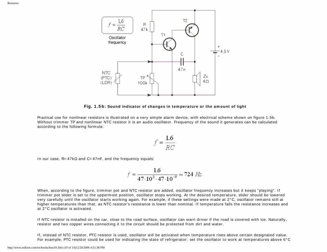
Fig. 1.5b: Sound indicator of changes in temperature or the amount of light
Practical use for nonlinear resistors is illustrated on a very simple alarm device, with electrical scheme shown on figure 1.5b. Without trimmer TP and nonlinear NTC resistor it is an audio oscillator. Frequency of the sound it generates can be calculated according to the following formula:
In our case, R=47kΩ and C=47nF, and the frequency equals:
When, according to the figure, trimmer pot and NTC resistor are added, oscillator frequency increases but it keeps "playing". If trimmer pot slider is set to the uppermost position, oscillator stops working. At the desired temperature, slider should be lowered very carefully until the oscillator starts working again. For example, if these settings were made at 2°C, oscillator remains still at higher temperatures than that, as NTC resistor's resistance is lower than nominal. If temperature falls the resistance increases and at 2°C oscillator is activated.
If NTC resistor is installed on the car, close to the road surface, oscillator can warn driver if the road is covered with ice. Naturally, resistor and two copper wires connecting it to the circuit should be protected from dirt and water.
If, instead of NTC resistor, PTC resistor is used, oscillator will be activated when temperature rises above certain designated value. For example, PTC resistor could be used for indicating the state of refrigerator: set the oscillator to work at temperatures above 6°C
http://www.mikroe.com/en/books/keu/01.htm (10 of 14)12/20/2006 4:51:38 PM
Resistors
via trimmer TP, and the loud sound will signal if anything's wrong with the fridge.
Instead of NTC, we could use LDR resistor - oscillator would be blocked as long as there is certain amount of light present. In this way, we could make a simple alarm system for rooms where light must be always on.
LDR can be coupled with resistor R. In that case, oscillator works when the light is present, otherwise it is blocked. This could be an interesting alarm clock for huntsmen and fishermen who would like to get up in the crack of dawn, but only if the weather is clear. In the desired moment in the early morning, pot slider should be set to the uppermost position. Then, it should be carefully lowered, until the oscillator is started - this the desired position of the slider. During the night, oscillator will be blocked, since there is no light and LDR resistance is very high. As amount of light increases in the morning, LDR resistance drops and the oscillator is activated when LDR is illuminated with the accurate amount of light matching the previous settings.
Trimmer pot from the figure 1.5b is used for fine adjustments. Aside from that, it can be used for modifying the circuit, if needed. Thus, TP from figure 1.5b can be used for setting the oscillator to activate under different conditions (higher or lower temperature or amount of light).
1.5 Potentiometers
Potentiometers (also called pots) are variable resistors, used as voltage or current regulators in electronic circuits. By means of construction, they can be divided into 2 groups: coated and coiled.
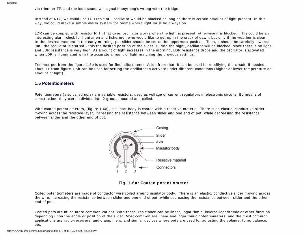
With coated potentiometers, (figure 1.6a), insulator body is coated with a resistive material. There is an elastic, conductive slider moving across the resistive layer, increasing the resistance between slider and one end of pot, while decreasing the resistance between slider and the other end of pot.
Fig. 1.6a: Coated potentiometer
Coiled potentiometers are made of conductor wire coiled around insulator body. There is an elastic, conductive slider moving across the wire, increasing the resistance between slider and one end of pot, while decreasing the resistance between slider and the other end of pot.
Coated pots are much more common variant. With these, resistance can be linear, logarithmic, inverse-logarithmic or other function depending upon the angle or position of the slider. Most common are linear and logarithmic potentiometers, and the most common applications are radio-receivers, audio amplifiers, and similar devices where pots are used for adjusting the volume, tone, balance, etc.
http://www.mikroe.com/en/books/keu/01.htm (11 of 14)12/20/2006 4:51:38 PM
Resistors
Coiled potentiometers are used in devices which require increased accuracy and constancy of attributes. They feature higher dissipation than coated pots, and are therefore a necessity in high current circuits.
Potentiometer resistance is commonly of E6 series, most frequently used multipliers including 1, 2.2 and 4.7. Standard tolerance values include 30%, 20%, 10% (and 5% for coiled pots).
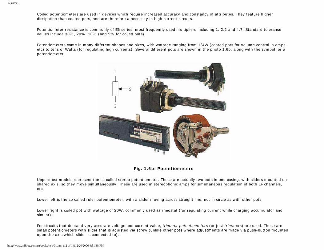
Potentiometers come in many different shapes and sizes, with wattage ranging from 1/4W (coated pots for volume control in amps, etc) to tens of Watts (for regulating high currents). Several different pots are shown in the photo 1.6b, along with the symbol for a potentiometer.
Fig. 1.6b: Potentiometers
Uppermost models represent the so called stereo potentiometer. These are actually two pots in one casing, with sliders mounted on shared axis, so they move simultaneously. These are used in stereophonic amps for simultaneous regulation of both LF channels, etc.
Lower left is the so called ruler potentiometer, with a slider moving across straight line, not in circle as with other pots.
Lower right is coiled pot with wattage of 20W, commonly used as rheostat (for regulating current while charging accumulator and similar).
For circuits that demand very accurate voltage and current value, trimmer potentiometers (or just trimmers) are used. These are small potentiometers with slider that is adjusted via screw (unlike other pots where adjustments are made via push-button mounted upon the axis which slider is connected to).
http://www.mikroe.com/en/books/keu/01.htm (12 of 14)12/20/2006 4:51:38 PM
Resistors
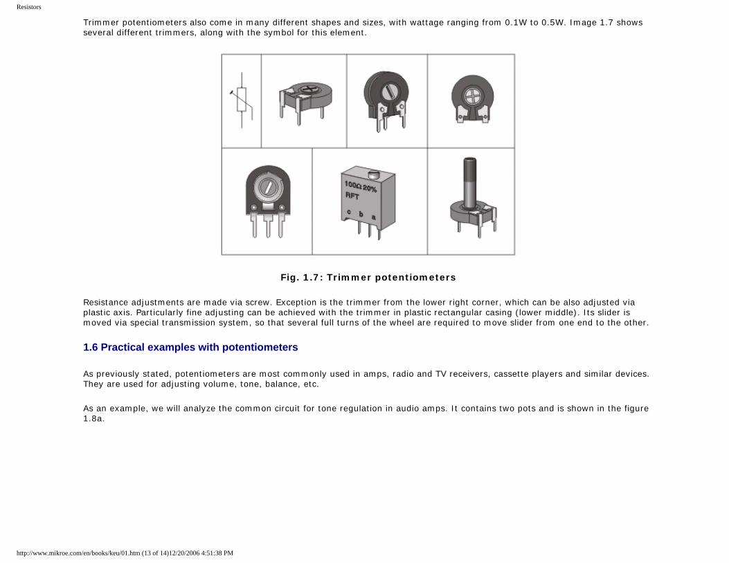
Trimmer potentiometers also come in many different shapes and sizes, with wattage ranging from 0.1W to 0.5W. Image 1.7 shows several different trimmers, along with the symbol for this element.
Fig. 1.7: Trimmer potentiometers
Resistance adjustments are made via screw. Exception is the trimmer from the lower right corner, which can be also adjusted via plastic axis. Particularly fine adjusting can be achieved with the trimmer in plastic rectangular casing (lower middle). Its slider is moved via special transmission system, so that several full turns of the wheel are required to move slider from one end to the other.
1.6 Practical examples with potentiometers
As previously stated, potentiometers are most commonly used in amps, radio and TV receivers, cassette players and similar devices. They are used for adjusting volume, tone, balance, etc.
As an example, we will analyze the common circuit for tone regulation in audio amps. It contains two pots and is shown in the figure 1.8a.
http://www.mikroe.com/en/books/keu/01.htm (13 of 14)12/20/2006 4:51:38 PM
Resistors
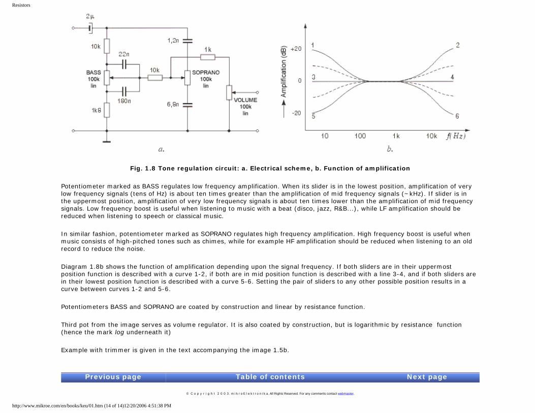
Fig. 1.8 Tone regulation circuit: a. Electrical scheme, b. Function of amplification
Potentiometer marked as BASS regulates low frequency amplification. When its slider is in the lowest position, amplification of very low frequency signals (tens of Hz) is about ten times greater than the amplification of mid frequency signals (~kHz). If slider is in the uppermost position, amplification of very low frequency signals is about ten times lower than the amplification of mid frequency signals. Low frequency boost is useful when listening to music with a beat (disco, jazz, R&B...), while LF amplification should be reduced when listening to speech or classical music.
In similar fashion, potentiometer marked as SOPRANO regulates high frequency amplification. High frequency boost is useful when music consists of high-pitched tones such as chimes, while for example HF amplification should be reduced when listening to an old record to reduce the noise.
Diagram 1.8b shows the function of amplification depending upon the signal frequency. If both sliders are in their uppermost position function is described with a curve 1-2, if both are in mid position function is described with a line 3-4, and if both sliders are in their lowest position function is described with a curve 5-6. Setting the pair of sliders to any other possible position results in a curve between curves 1-2 and 5-6.
Potentiometers BASS and SOPRANO are coated by construction and linear by resistance function.
Third pot from the image serves as volume regulator. It is also coated by construction, but is logarithmic by resistance function (hence the mark log underneath it)
Example with trimmer is given in the text accompanying the image 1.5b.
Previous page Table of contents Next page
© C o p y r i g h t 2 0 0 3. m i k r o E l e k t r o n i k a. All Rights Reserved. For any comments contact webmaster.
http://www.mikroe.com/en/books/keu/01.htm (14 of 14)12/20/2006 4:51:38 PM
Capacitors
Understanding Electronic Components
IndexDevelopment systemsContact us
Previous page Table of contents Next page
2. Capacitors
Capacitors are common components of electronic circuits, used almost as frequently as resistors. Basic difference between the two is the fact that capacitor resistance (called reactance) depends on voltage frequency, not only on capacitors' features. Common mark for reactance is Xc and it can be calculated using the following formula:
f representing the frequency in Hz and C representing the capacity in Farads.
For example, 5nF-capacitor's reactance at f=125kHz equals:
while, at f=1.25MHz, it equals:
Capacitor has infinitely high reactance for direct current, because f=0.
Capacitors are used in circuits for filtering signals of specified frequency. They are common components of electrical filters, oscillator circuits, etc.
Basic characteristic of capacitor is its capacity - higher the capacity is, higher is the amount of electricity capacitor can accumulate. Capacity is measured in Farads (F). As one Farad represents fairly high capacity value, microfarad (µF), nanofarad (nF) and picofarad (pF) are commonly used. As a reminder, relations between units are:
1F=106µF=109nF=1012pF,
http://www.mikroe.com/en/books/keu/02.htm (1 of 8)12/20/2006 4:51:41 PM
Capacitors
that is 1µF=1000nF and 1nF=1000pF. It is essential to remember this notation, as same values may be marked differently in different electrical schemes. For example, 1500pF may be used interchangeably with 1.5nF, 100nF may replace 0.1µF, etc. Bear in mind that simpler notation system is used, as with resistors. If the mark by the capacitor in the scheme reads 120 (or 120E) capacity equals 120pF, 1n2 stands for 1.2nF, n22 stands for 0.22nF, while .1µ (or .1u) stands for 0.1µF capacity and so forth.
Capacitors come in various shapes and sizes, depending on their capacity, working voltage, insulator type, temperature coefficient and other factors. All capacitors can divided in two groups: those with changeable capacity values and those with fixed capacity values. These will covered in the following chapters.
2.1 Block-capacitors
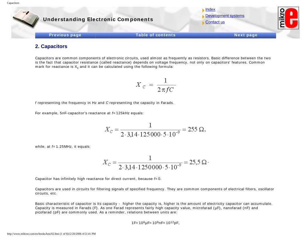
Capacitors with fixed capacity values (the so called block-capacitors) consist of two thin metal bands, separated by thin insulator foil. Most commonly used material for these bands is aluminum, while the common materials used for insulator foil include paper, ceramics, mica, etc after which the capacitors get named. A number of different block-capacitors are shown in the photo below. A symbol for a capacitor is in the upper right corner of the image.
Fig. 2.1: Block capacitors
Most of the capacitors, block-capacitors included, are nonpolarized components, meaning that both of their connectors are equivalent in respect of solder. Electrolytic capacitors represent the exception as their polarity is of importance, which will be covered in the following chapters.
2.1.1 Marking the block-capacitors
Commonly, capacitors are marked by a number representing the capacity value printed on the capacitor. Beside this value, number representing the maximal capacitor working voltage is mandatory, and sometimes tolerance, temperature coefficient and some other values are printed too. If, for example, capacitor mark in the scheme reads 5nF/40V, it means that capacitor with 5nF capacity value is used and that its maximal working voltage is 40v. Any other 5nF capacitor with higher maximal working voltage can be
http://www.mikroe.com/en/books/keu/02.htm (2 of 8)12/20/2006 4:51:41 PM
Capacitors
used instead, but they are as a rule larger and more expensive.
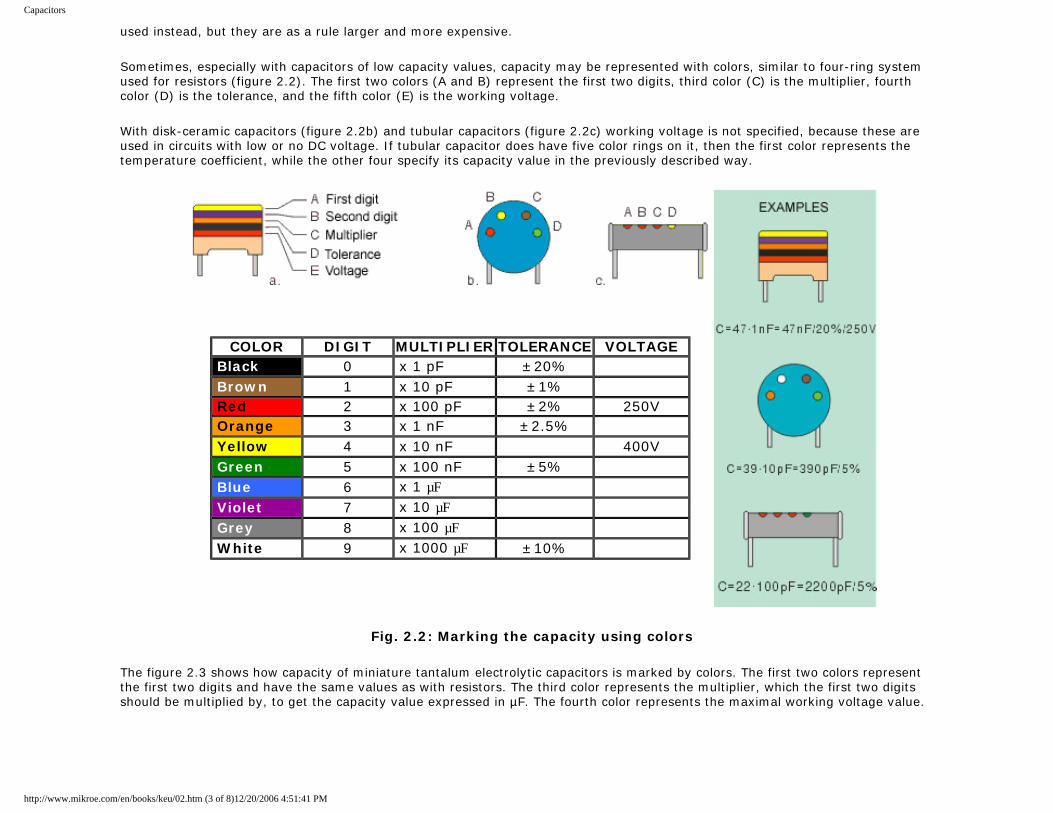
Sometimes, especially with capacitors of low capacity values, capacity may be represented with colors, similar to four-ring system used for resistors (figure 2.2). The first two colors (A and B) represent the first two digits, third color (C) is the multiplier, fourth color (D) is the tolerance, and the fifth color (E) is the working voltage.
With disk-ceramic capacitors (figure 2.2b) and tubular capacitors (figure 2.2c) working voltage is not specified, because these are used in circuits with low or no DC voltage. If tubular capacitor does have five color rings on it, then the first color represents the temperature coefficient, while the other four specify its capacity value in the previously described way.
COLOR DIGIT MULTIPLIER TOLERANCE VOLTAGE Black 0 x 1 pF ±20% Brown 1 x 10 pF ±1% Red 2 x 100 pF ±2% 250V Orange 3 x 1 nF ±2.5% Yellow 4 x 10 nF 400V Green 5 x 100 nF ±5% Blue 6 x 1 µF Violet 7 x 10 µF Grey 8 x 100 µF White 9 x 1000 µF ±10%
Fig. 2.2: Marking the capacity using colors
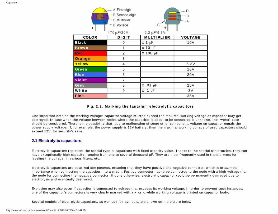
The figure 2.3 shows how capacity of miniature tantalum electrolytic capacitors is marked by colors. The first two colors represent the first two digits and have the same values as with resistors. The third color represents the multiplier, which the first two digits should be multiplied by, to get the capacity value expressed in µF. The fourth color represents the maximal working voltage value.
http://www.mikroe.com/en/books/keu/02.htm (3 of 8)12/20/2006 4:51:41 PM
Capacitors
COLOR DIGIT MULTIPLIER VOLTAGE Black 0 x 1 µF 10V Brown 1 x 10 µF Red 2 x 100 µF Orange 3 Yellow 4 6.3V Green 5 16V Blue 6 20V Violet 7 Grey 8 x .01 µF 25V White 9 x .1 µF 3V Pink 35V
Fig. 2.3: Marking the tantalum electrolytic capacitors
One important note on the working voltage: capacitor voltage mustn't exceed the maximal working voltage as capacitor may get destroyed. In case when the voltage between nodes where the capacitor is about to be connected is unknown, the "worst" case should be considered. There is the possibility that, due to malfunction of some other component, voltage on capacitor equals the power supply voltage. If, for example, the power supply is 12V battery, then the maximal working voltage of used capacitors should exceed 12V, for security's sake.
2.1 Electrolytic capacitors
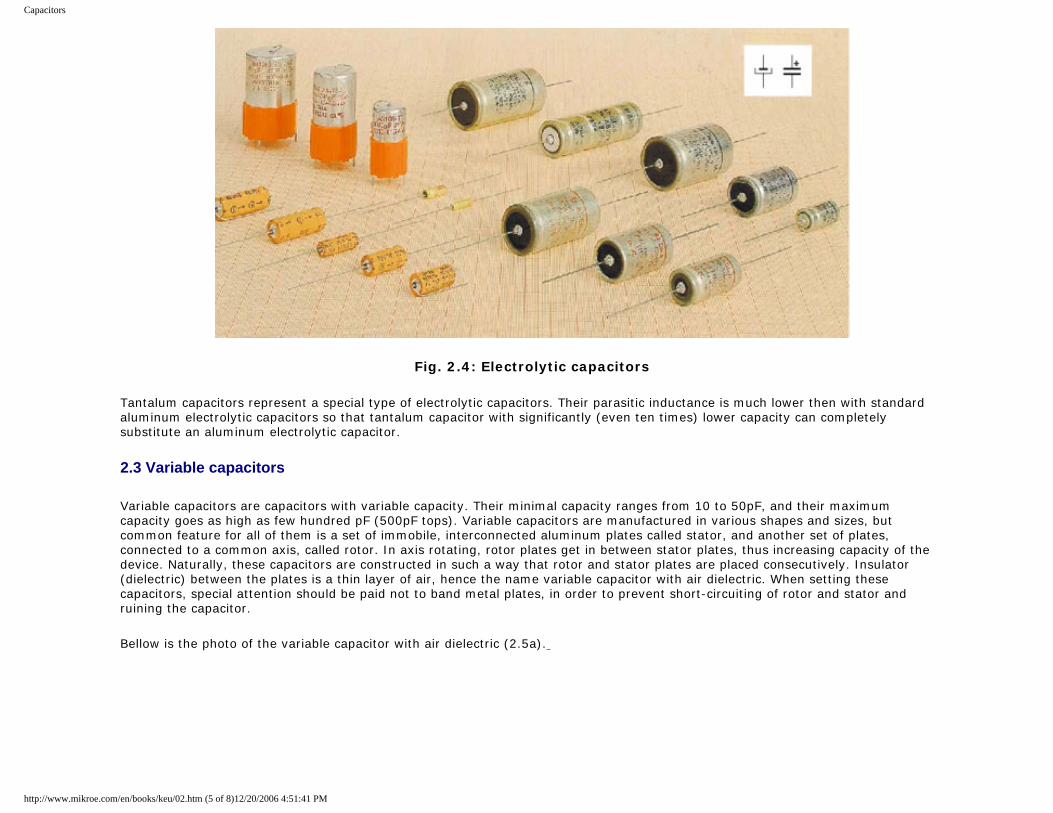
Electrolytic capacitors represent the special type of capacitors with fixed capacity value. Thanks to the special construction, they can have exceptionally high capacity, ranging from one to several thousand µF. They are most frequently used in transformers for leveling the voltage, in various filters, etc.
Electrolytic capacitors are polarized components, meaning that they have positive and negative connector, which is of outmost importance when connecting the capacitor into a circuit. Positive connector has to be connected to the node with a high voltage than the node for connecting the negative connector. If done otherwise, electrolytic capacitor could be permanently damaged due to electrolysis and eventually destroyed.
Explosion may also occur if capacitor is connected to voltage that exceeds its working voltage. In order to prevent such instances, one of the capacitor's connectors is very clearly marked with a + or -, while working voltage is printed on capacitor body.
Several models of electrolytic capacitors, as well as their symbols, are shown on the picture below.
http://www.mikroe.com/en/books/keu/02.htm (4 of 8)12/20/2006 4:51:41 PM
Capacitors
Fig. 2.4: Electrolytic capacitors
Tantalum capacitors represent a special type of electrolytic capacitors. Their parasitic inductance is much lower then with standard aluminum electrolytic capacitors so that tantalum capacitor with significantly (even ten times) lower capacity can completely substitute an aluminum electrolytic capacitor.
2.3 Variable capacitors
Variable capacitors are capacitors with variable capacity. Their minimal capacity ranges from 10 to 50pF, and their maximum capacity goes as high as few hundred pF (500pF tops). Variable capacitors are manufactured in various shapes and sizes, but common feature for all of them is a set of immobile, interconnected aluminum plates called stator, and another set of plates, connected to a common axis, called rotor. In axis rotating, rotor plates get in between stator plates, thus increasing capacity of the device. Naturally, these capacitors are constructed in such a way that rotor and stator plates are placed consecutively. Insulator (dielectric) between the plates is a thin layer of air, hence the name variable capacitor with air dielectric. When setting these capacitors, special attention should be paid not to band metal plates, in order to prevent short-circuiting of rotor and stator and ruining the capacitor.
Bellow is the photo of the variable capacitor with air dielectric (2.5a).
http://www.mikroe.com/en/books/keu/02.htm (5 of 8)12/20/2006 4:51:41 PM
Capacitors
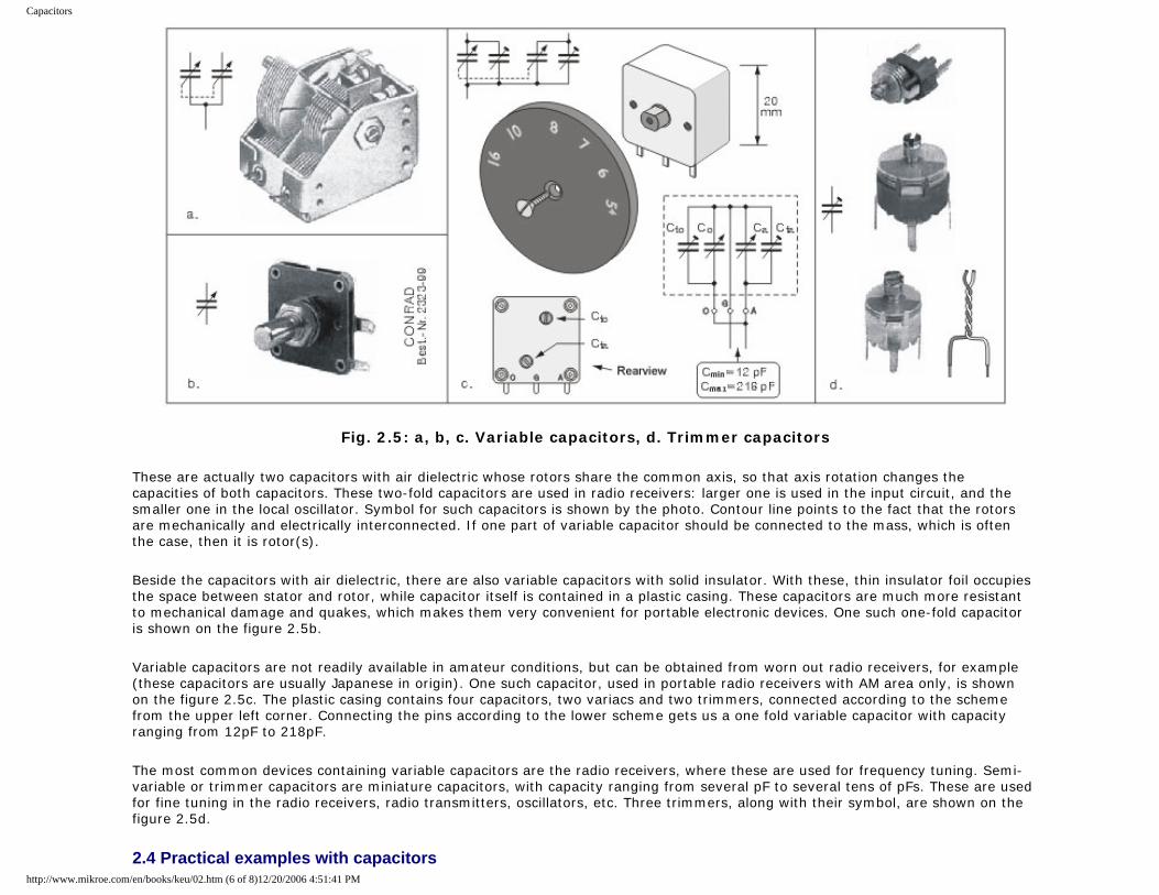
Fig. 2.5: a, b, c. Variable capacitors, d. Trimmer capacitors
These are actually two capacitors with air dielectric whose rotors share the common axis, so that axis rotation changes the capacities of both capacitors. These two-fold capacitors are used in radio receivers: larger one is used in the input circuit, and the smaller one in the local oscillator. Symbol for such capacitors is shown by the photo. Contour line points to the fact that the rotors are mechanically and electrically interconnected. If one part of variable capacitor should be connected to the mass, which is often the case, then it is rotor(s).
Beside the capacitors with air dielectric, there are also variable capacitors with solid insulator. With these, thin insulator foil occupies the space between stator and rotor, while capacitor itself is contained in a plastic casing. These capacitors are much more resistant to mechanical damage and quakes, which makes them very convenient for portable electronic devices. One such one-fold capacitor is shown on the figure 2.5b.
Variable capacitors are not readily available in amateur conditions, but can be obtained from worn out radio receivers, for example (these capacitors are usually Japanese in origin). One such capacitor, used in portable radio receivers with AM area only, is shown on the figure 2.5c. The plastic casing contains four capacitors, two variacs and two trimmers, connected according to the scheme from the upper left corner. Connecting the pins according to the lower scheme gets us a one fold variable capacitor with capacity ranging from 12pF to 218pF.
The most common devices containing variable capacitors are the radio receivers, where these are used for frequency tuning. Semi-variable or trimmer capacitors are miniature capacitors, with capacity ranging from several pF to several tens of pFs. These are used for fine tuning in the radio receivers, radio transmitters, oscillators, etc. Three trimmers, along with their symbol, are shown on the figure 2.5d.
2.4 Practical examples with capacitorshttp://www.mikroe.com/en/books/keu/02.htm (6 of 8)12/20/2006 4:51:41 PM
Capacitors
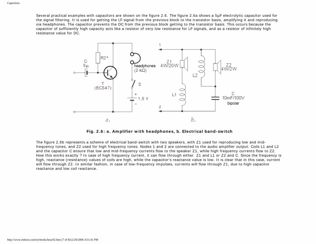
Several practical examples with capacitors are shown on the figure 2.6. The figure 2.6a shows a 5µF electrolytic capacitor used for the signal filtering. It is used for getting the LF signal from the previous block to the transistor basis, amplifying it and reproducing via headphones. The capacitor prevents the DC from the previous block getting to the transistor basis. This occurs because the capacitor of sufficiently high capacity acts like a resistor of very low resistance for LF signals, and as a resistor of infinitely high resistance value for DC.
Fig. 2.6: a. Amplifier with headphones, b. Electrical band-switch
The figure 2.6b represents a scheme of electrical band-switch with two speakers, with Z1 used for reproducing low and mid-frequency tones, and Z2 used for high frequency tones. Nodes 1 and 2 are connected to the audio amplifier output. Coils L1 and L2 and the capacitor C ensure that low and mid-frequency currents flow to the speaker Z1, while high frequency currents flow to Z2. How this works exactly ? In case of high frequency current, it can flow through either Z1 and L1 or Z2 and C. Since the frequency is high, reactance (resistance) values of coils are high, while the capacitor's reactance value is low. It is clear that in this case, current will flow through Z2. In similar fashion, in case of low-frequency impulses, currents will flow through Z1, due to high capacitor reactance and low coil reactance.
http://www.mikroe.com/en/books/keu/02.htm (7 of 8)12/20/2006 4:51:41 PM
Capacitors
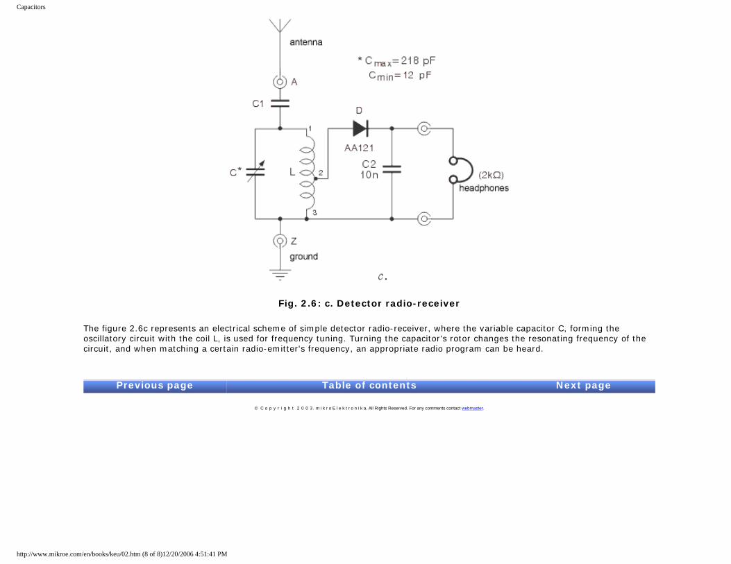
Fig. 2.6: c. Detector radio-receiver
The figure 2.6c represents an electrical scheme of simple detector radio-receiver, where the variable capacitor C, forming the oscillatory circuit with the coil L, is used for frequency tuning. Turning the capacitor's rotor changes the resonating frequency of the circuit, and when matching a certain radio-emitter's frequency, an appropriate radio program can be heard.
Previous page Table of contents Next page
© C o p y r i g h t 2 0 0 3. m i k r o E l e k t r o n i k a. All Rights Reserved. For any comments contact webmaster.
http://www.mikroe.com/en/books/keu/02.htm (8 of 8)12/20/2006 4:51:41 PM
Solenoids and transformers
Understanding Electronic Components
IndexDevelopment systemsContact us
Previous page Table of contents Next page
3. Coils and transformers
3.1 Coils
Coils are not that common components of electronic devices as resistors and capacitors are. They are encountered in various oscillators, radio-receivers, radio-emitters and similar devices containing oscillatory circuits. In amateur conditions, coil can be made by coiling one or more layers of isolated copper wire onto a cylindrical insulator body (PVC, cardboard, etc.) in a specified fashion. Factory made coils come in different shapes and sizes, but the common feature for all of them is an insulator body with coiled copper wire.
Basic characteristic of every coil is its inductance. Inductance is measured in Henry (H), but more common are milihenry (mH) and microhenry (µH) as one Henry is quite high inductance value. As a reminder:
1H = 1000mH = 106 µH.
Coil reactance is marked by XL, and can be calculated using the following formula:
where f represents the frequency of coil voltage in Hz and the L represents the coil inductance in H.
For example, if f equals 684 kHz, while L=0.6 mH, coil reactance will be:
The same coil would have three times higher reactive resistance at three times higher frequency and vice versa. As can be seen from the formula above, coil reactance is in direct proportion to voltage frequency, so that coils, as well as capacitors, are used in different circuits for filtering voltage of specified frequency. Note that coil reactance equals zero for DC, for f=0 in that case.
Several coils are shown on the figures 3.1, 3.2, 3.3, and 3.4.
The simplest form of coil is single-layer air core coil. It is made of cylindrical insulator body (PVC, cardboard, etc.) wrapped in isolated copper wire in specific pattern, as shown on the figure 3.1. On the figure 3.1a, curls have a certain amount of space left between them, while the common practice is to coil the wire with practically no space left between curls. To prevent coil unfolding, wire ends should be put through little holes as shown on the figure, but some sticky tape could also do the job.
http://www.mikroe.com/en/books/keu/03.htm (1 of 11)12/20/2006 4:51:45 PM
Solenoids and transformers
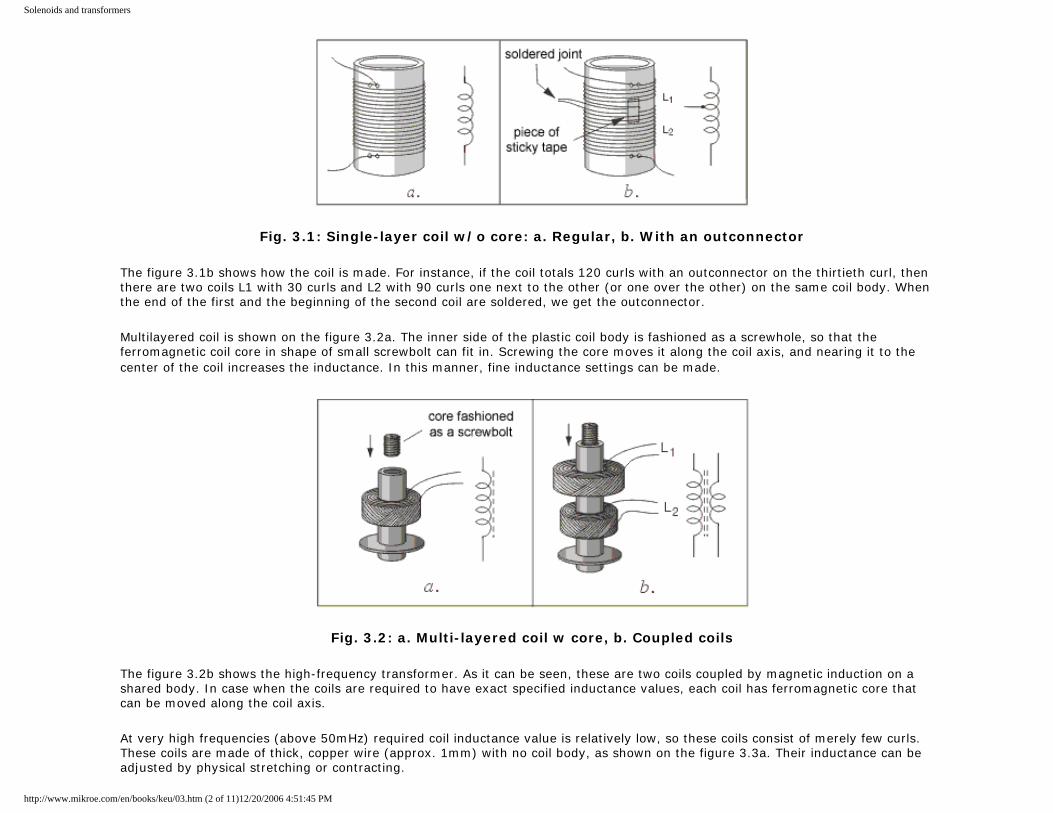
Fig. 3.1: Single-layer coil w/o core: a. Regular, b. With an outconnector
The figure 3.1b shows how the coil is made. For instance, if the coil totals 120 curls with an outconnector on the thirtieth curl, then there are two coils L1 with 30 curls and L2 with 90 curls one next to the other (or one over the other) on the same coil body. When the end of the first and the beginning of the second coil are soldered, we get the outconnector.
Multilayered coil is shown on the figure 3.2a. The inner side of the plastic coil body is fashioned as a screwhole, so that the ferromagnetic coil core in shape of small screwbolt can fit in. Screwing the core moves it along the coil axis, and nearing it to the center of the coil increases the inductance. In this manner, fine inductance settings can be made.
Fig. 3.2: a. Multi-layered coil w core, b. Coupled coils
The figure 3.2b shows the high-frequency transformer. As it can be seen, these are two coils coupled by magnetic induction on a shared body. In case when the coils are required to have exact specified inductance values, each coil has ferromagnetic core that can be moved along the coil axis.
At very high frequencies (above 50mHz) required coil inductance value is relatively low, so these coils consist of merely few curls. These coils are made of thick, copper wire (approx. 1mm) with no coil body, as shown on the figure 3.3a. Their inductance can be adjusted by physical stretching or contracting.
http://www.mikroe.com/en/books/keu/03.htm (2 of 11)12/20/2006 4:51:45 PM
Solenoids and transformers
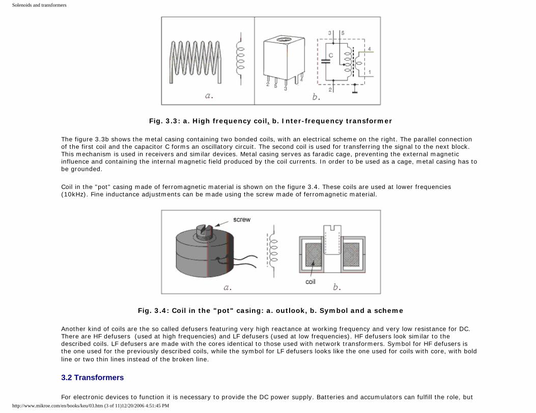
Fig. 3.3: a. High frequency coil, b. Inter-frequency transformer
The figure 3.3b shows the metal casing containing two bonded coils, with an electrical scheme on the right. The parallel connection of the first coil and the capacitor C forms an oscillatory circuit. The second coil is used for transferring the signal to the next block. This mechanism is used in receivers and similar devices. Metal casing serves as faradic cage, preventing the external magnetic influence and containing the internal magnetic field produced by the coil currents. In order to be used as a cage, metal casing has to be grounded.
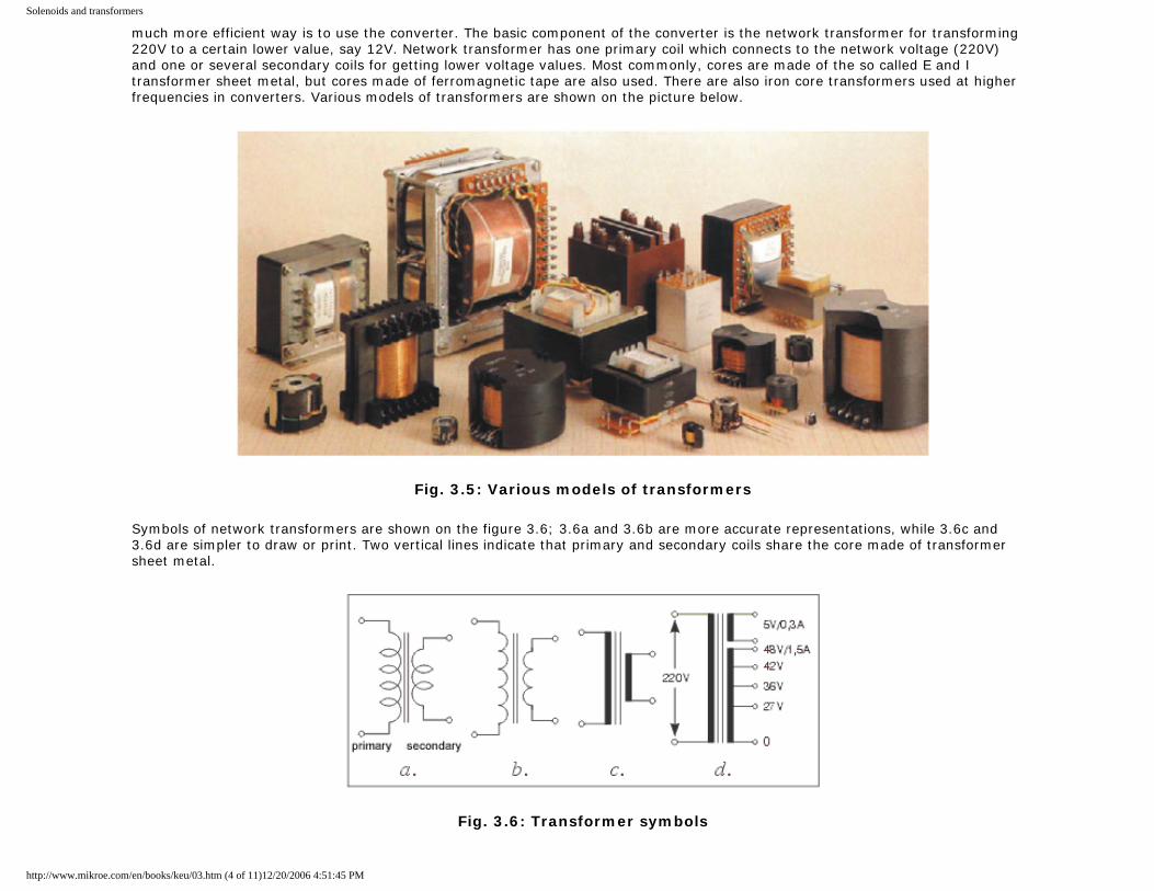
Coil in the "pot" casing made of ferromagnetic material is shown on the figure 3.4. These coils are used at lower frequencies (10kHz). Fine inductance adjustments can be made using the screw made of ferromagnetic material.
Fig. 3.4: Coil in the "pot" casing: a. outlook, b. Symbol and a scheme
Another kind of coils are the so called defusers featuring very high reactance at working frequency and very low resistance for DC. There are HF defusers (used at high frequencies) and LF defusers (used at low frequencies). HF defusers look similar to the described coils. LF defusers are made with the cores identical to those used with network transformers. Symbol for HF defusers is the one used for the previously described coils, while the symbol for LF defusers looks like the one used for coils with core, with bold line or two thin lines instead of the broken line.
3.2 Transformers
For electronic devices to function it is necessary to provide the DC power supply. Batteries and accumulators can fulfill the role, but http://www.mikroe.com/en/books/keu/03.htm (3 of 11)12/20/2006 4:51:45 PM
Solenoids and transformers
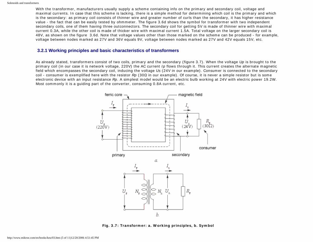
much more efficient way is to use the converter. The basic component of the converter is the network transformer for transforming 220V to a certain lower value, say 12V. Network transformer has one primary coil which connects to the network voltage (220V) and one or several secondary coils for getting lower voltage values. Most commonly, cores are made of the so called E and I transformer sheet metal, but cores made of ferromagnetic tape are also used. There are also iron core transformers used at higher frequencies in converters. Various models of transformers are shown on the picture below.
Fig. 3.5: Various models of transformers
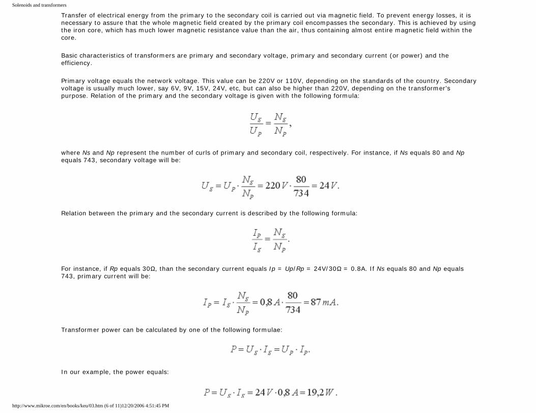
Symbols of network transformers are shown on the figure 3.6; 3.6a and 3.6b are more accurate representations, while 3.6c and 3.6d are simpler to draw or print. Two vertical lines indicate that primary and secondary coils share the core made of transformer sheet metal.
Fig. 3.6: Transformer symbols
http://www.mikroe.com/en/books/keu/03.htm (4 of 11)12/20/2006 4:51:45 PM
Solenoids and transformers
With the transformer, manufacturers usually supply a scheme containing info on the primary and secondary coil, voltage and maximal currents. In case that this scheme is lacking, there is a simple method for determining which coil is the primary and which is the secondary: as primary coil consists of thinner wire and greater number of curls than the secondary, it has higher resistance value - the fact that can be easily tested by ohmmeter. The figure 3.6d shows the symbol for transformer with two independent secondary coils, one of them having three outconnectors. The secondary coil for getting 5V is made of thinner wire with maximal current 0.3A, while the other coil is made of thicker wire with maximal current 1.5A. Total voltage on the larger secondary coil is 48V, as shown on the figure 3.6d. Note that voltage values other than those marked on the scheme can be produced - for example, voltage between nodes marked as 27V and 36V equals 9V, voltage between nodes marked as 27V and 42V equals 15V, etc.
3.2.1 Working principles and basic characteristics of transformers
As already stated, transformers consist of two coils, primary and the secondary (figure 3.7). When the voltage Up is brought to the primary coil (in our case it is network voltage, 220V) the AC current Ip flows through it. This current creates the alternate magnetic field which encompasses the secondary coil, inducing the voltage Us (24V in our example). Consumer is connected to the secondary coil - consumer is exemplified here with the resistor Rp (30Ω in our example). Of course, it is never a simple resistor but is some electronic device with an input resistance Rp. A simplest model would be an electric bulb working at 24V with electric power 19.2W. Most commonly it is a guiding part of the converter, consuming 0.8A current, etc.
Fig. 3.7: Transformer: a. Working principles, b. Symbol
http://www.mikroe.com/en/books/keu/03.htm (5 of 11)12/20/2006 4:51:45 PM
Solenoids and transformers
Transfer of electrical energy from the primary to the secondary coil is carried out via magnetic field. To prevent energy losses, it is necessary to assure that the whole magnetic field created by the primary coil encompasses the secondary. This is achieved by using the iron core, which has much lower magnetic resistance value than the air, thus containing almost entire magnetic field within the core.
Basic characteristics of transformers are primary and secondary voltage, primary and secondary current (or power) and the efficiency.
Primary voltage equals the network voltage. This value can be 220V or 110V, depending on the standards of the country. Secondary voltage is usually much lower, say 6V, 9V, 15V, 24V, etc, but can also be higher than 220V, depending on the transformer's purpose. Relation of the primary and the secondary voltage is given with the following formula:
where Ns and Np represent the number of curls of primary and secondary coil, respectively. For instance, if Ns equals 80 and Np equals 743, secondary voltage will be:
Relation between the primary and the secondary current is described by the following formula:
For instance, if Rp equals 30Ω, than the secondary current equals Ip = Up/Rp = 24V/30Ω = 0.8A. If Ns equals 80 and Np equals 743, primary current will be:
Transformer power can be calculated by one of the following formulae:
In our example, the power equals:
http://www.mikroe.com/en/books/keu/03.htm (6 of 11)12/20/2006 4:51:45 PM
Solenoids and transformers
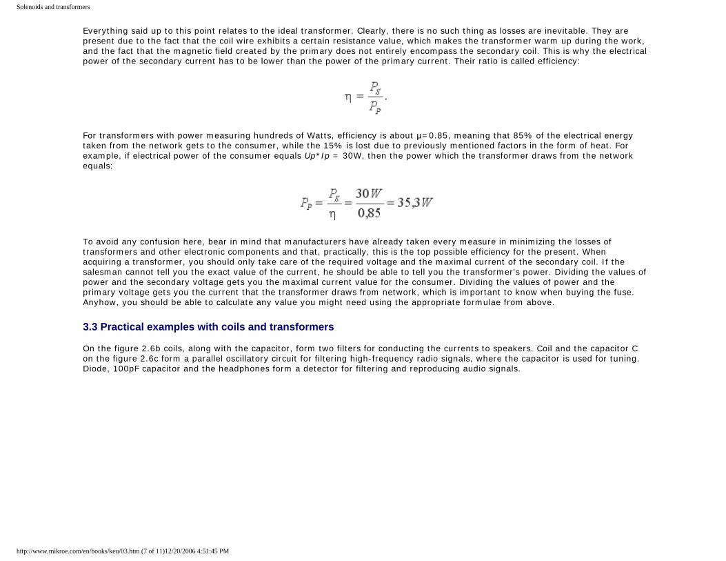
Everything said up to this point relates to the ideal transformer. Clearly, there is no such thing as losses are inevitable. They are present due to the fact that the coil wire exhibits a certain resistance value, which makes the transformer warm up during the work, and the fact that the magnetic field created by the primary does not entirely encompass the secondary coil. This is why the electrical power of the secondary current has to be lower than the power of the primary current. Their ratio is called efficiency:
For transformers with power measuring hundreds of Watts, efficiency is about µ=0.85, meaning that 85% of the electrical energy taken from the network gets to the consumer, while the 15% is lost due to previously mentioned factors in the form of heat. For example, if electrical power of the consumer equals Up*Ip = 30W, then the power which the transformer draws from the network equals:
To avoid any confusion here, bear in mind that manufacturers have already taken every measure in minimizing the losses of transformers and other electronic components and that, practically, this is the top possible efficiency for the present. When acquiring a transformer, you should only take care of the required voltage and the maximal current of the secondary coil. If the salesman cannot tell you the exact value of the current, he should be able to tell you the transformer's power. Dividing the values of power and the secondary voltage gets you the maximal current value for the consumer. Dividing the values of power and the primary voltage gets you the current that the transformer draws from network, which is important to know when buying the fuse. Anyhow, you should be able to calculate any value you might need using the appropriate formulae from above.
3.3 Practical examples with coils and transformers On the figure 2.6b coils, along with the capacitor, form two filters for conducting the currents to speakers. Coil and the capacitor C on the figure 2.6c form a parallel oscillatory circuit for filtering high-frequency radio signals, where the capacitor is used for tuning. Diode, 100pF capacitor and the headphones form a detector for filtering and reproducing audio signals.
http://www.mikroe.com/en/books/keu/03.htm (7 of 11)12/20/2006 4:51:45 PM
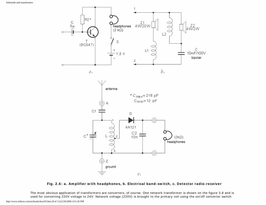
Solenoids and transformers
Fig. 2.6: a. Amplifier with headphones, b. Electrical band-switch, c. Detector radio-receiver
The most obvious application of transformers are converters, of course. One network transformer is shown on the figure 3.8 and is used for converting 220V voltage to 24V. Network voltage (220V) is brought to the primary coil using the on/off converter switch
http://www.mikroe.com/en/books/keu/03.htm (8 of 11)12/20/2006 4:51:45 PM
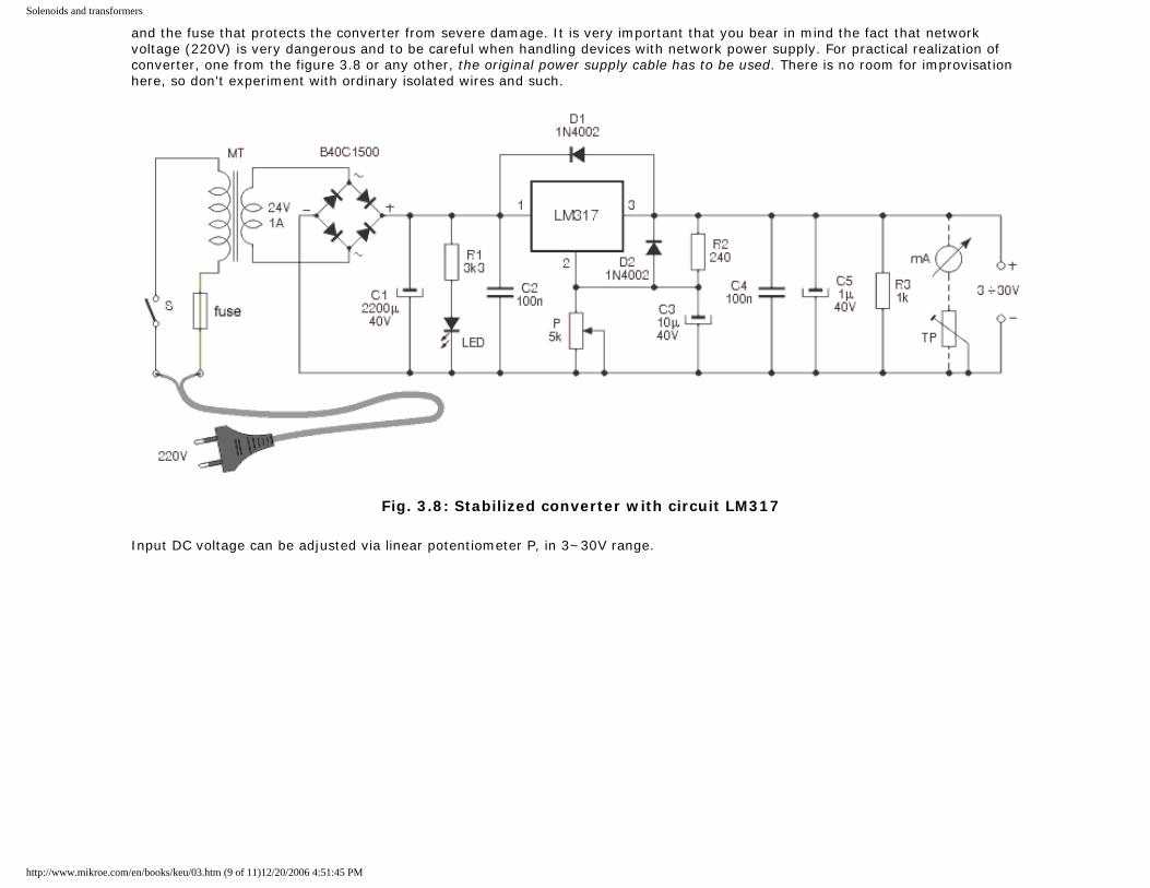
Solenoids and transformers
and the fuse that protects the converter from severe damage. It is very important that you bear in mind the fact that network voltage (220V) is very dangerous and to be careful when handling devices with network power supply. For practical realization of converter, one from the figure 3.8 or any other, the original power supply cable has to be used. There is no room for improvisation here, so don't experiment with ordinary isolated wires and such.
Fig. 3.8: Stabilized converter with circuit LM317
Input DC voltage can be adjusted via linear potentiometer P, in 3~30V range.
http://www.mikroe.com/en/books/keu/03.htm (9 of 11)12/20/2006 4:51:45 PM
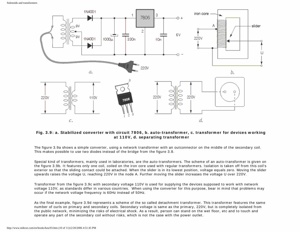
Solenoids and transformers
Fig. 3.9: a. Stabilized converter with circuit 7806, b. auto-transformer, c. transformer for devices working at 110V, d. separating transformer
The figure 3.9a shows a simple converter, using a network transformer with an outconnector on the middle of the secondary coil. This makes possible to use two diodes instead of the bridge from the figure 3.8.
Special kind of transformers, mainly used in laboratories, are the auto-transformers. The scheme of an auto-transformer is given on the figure 3.9b. It features only one coil, coiled on the iron core used with regular transformers. Isolation is taken off from this coil's exterior so that the sliding contact could be attached. When the slider is in its lowest position, voltage equals zero. Moving the slider upwards raises the voltage U, reaching 220V in the node A. Further moving the slider increases the voltage U over 220V.
Transformer from the figure 3.9c with secondary voltage 110V is used for supplying the devices supposed to work with network voltage 110V, as standards differ in various countries. When using the converter for this purpose, bear in mind that problems may occur if the network voltage frequency is 60Hz instead of 50Hz.
As the final example, figure 3.9d represents a scheme of the so called detachment transformer. This transformer features the same number of curls on primary and secondary coils. Secondary voltage is same as the primary, 220V, but is completely isolated from the public network, minimizing the risks of electrical shock. As a result, person can stand on the wet floor, etc and to touch and operate any part of the secondary coil without risks, which is not the case with the power outlet.
http://www.mikroe.com/en/books/keu/03.htm (10 of 11)12/20/2006 4:51:45 PM

Solenoids and transformers
Previous page Table of contents Next page
© C o p y r i g h t 2 0 0 3. m i k r o E l e k t r o n i k a. All Rights Reserved. For any comments contact webmaster.
http://www.mikroe.com/en/books/keu/03.htm (11 of 11)12/20/2006 4:51:45 PM
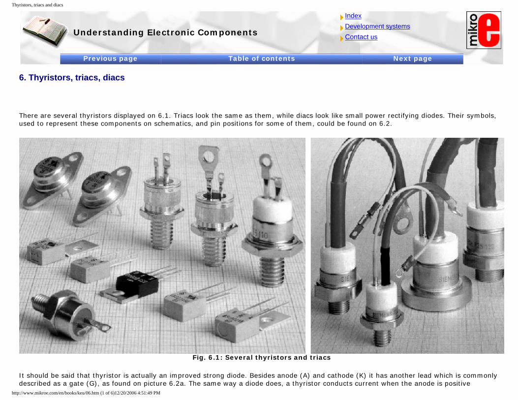
Thyristors, triacs and diacs
Understanding Electronic Components
IndexDevelopment systemsContact us
Previous page Table of contents Next page
6. Thyristors, triacs, diacs
There are several thyristors displayed on 6.1. Triacs look the same as them, while diacs look like small power rectifying diodes. Their symbols, used to represent these components on schematics, and pin positions for some of them, could be found on 6.2.
Fig. 6.1: Several thyristors and triacs
It should be said that thyristor is actually an improved strong diode. Besides anode (A) and cathode (K) it has another lead which is commonly described as a gate (G), as found on picture 6.2a. The same way a diode does, a thyristor conducts current when the anode is positive
http://www.mikroe.com/en/books/keu/06.htm (1 of 6)12/20/2006 4:51:49 PM

Thyristors, triacs and diacs
compared to the cathode, but only if the voltage on the gate is positive and high enough as well. When thyristor starts conducting (from anode to cathode) voltage on the gate is of no importance to us any longer, and thyristor can be switched off only by breaking the circuit on the anode side. For example, look at the picture 6.3. If the circuit was closed using switch S1, thyristor would not conduct electricity, and so bulb won't light. If, even for a very short time, switch S2 was closed, bulb would light. Only by opening S1 will shut the bulb again. thyristors are marked in some schematics as SCR, which is an acronym for Silicon Controlled Rectifier. Triac is very similar component to thyristor, with the difference that it can conduct electricity in both directions. It has three electrodes as well, called anode 1 (A1), anode 2 (A2), and gate (G). It is used for regulation of alternating current circuits. Devices such as hand drill speed controller or bulb light controller could be realized using a triac, which we will discuss at a later point. thyristors and triacs are marked alphanumerically, KT430, for example. In schematics it is common to find only their properties, like expected voltage and current, and not exact product mark. In those cases any thyristor or triac, satisfying given values, could be used. Low power thyristors and triacs are packed in same housings as transistors, but high power ones have completely different shell. These are shown on the upper side, and on the right of the picture 6.1. Pin placement of some more common thyristors and triacs is shown on picture 6.2 a and b. Diacs (6.2c), or two-way diodes as often referred to, are used together with thyristors and triacs. Their main property is that their resistance is very large until voltage on their ends exceeds some predefined value. That pass-through voltage is commonly 30V. So, while voltage is under 30V diac responds as any common large resistance resistor, and when voltage rises over 30V it acts as a low resistance resistor. Housing of a diac isn't different than packing of the common low power rectifying diode.
Fig. 6.2: Symbols and pin placements for: a - thyristor, b - triac, c - diac
http://www.mikroe.com/en/books/keu/06.htm (2 of 6)12/20/2006 4:51:49 PM
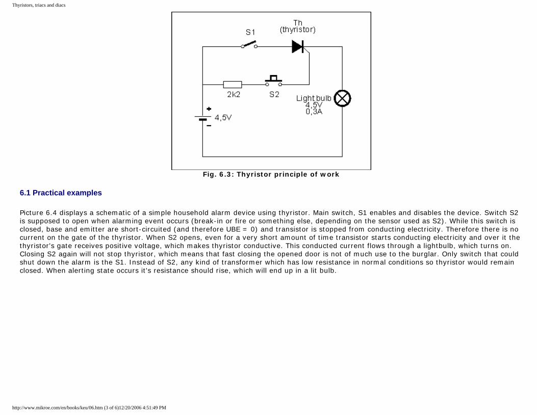
Thyristors, triacs and diacs
Fig. 6.3: Thyristor principle of work
6.1 Practical examples
Picture 6.4 displays a schematic of a simple household alarm device using thyristor. Main switch, S1 enables and disables the device. Switch S2 is supposed to open when alarming event occurs (break-in or fire or something else, depending on the sensor used as S2). While this switch is closed, base and emitter are short-circuited (and therefore UBE = 0) and transistor is stopped from conducting electricity. Therefore there is no current on the gate of the thyristor. When S2 opens, even for a very short amount of time transistor starts conducting electricity and over it the thyristor's gate receives positive voltage, which makes thyristor conductive. This conducted current flows through a lightbulb, which turns on. Closing S2 again will not stop thyristor, which means that fast closing the opened door is not of much use to the burglar. Only switch that could shut down the alarm is the S1. Instead of S2, any kind of transformer which has low resistance in normal conditions so thyristor would remain closed. When alerting state occurs it's resistance should rise, which will end up in a lit bulb.
http://www.mikroe.com/en/books/keu/06.htm (3 of 6)12/20/2006 4:51:49 PM
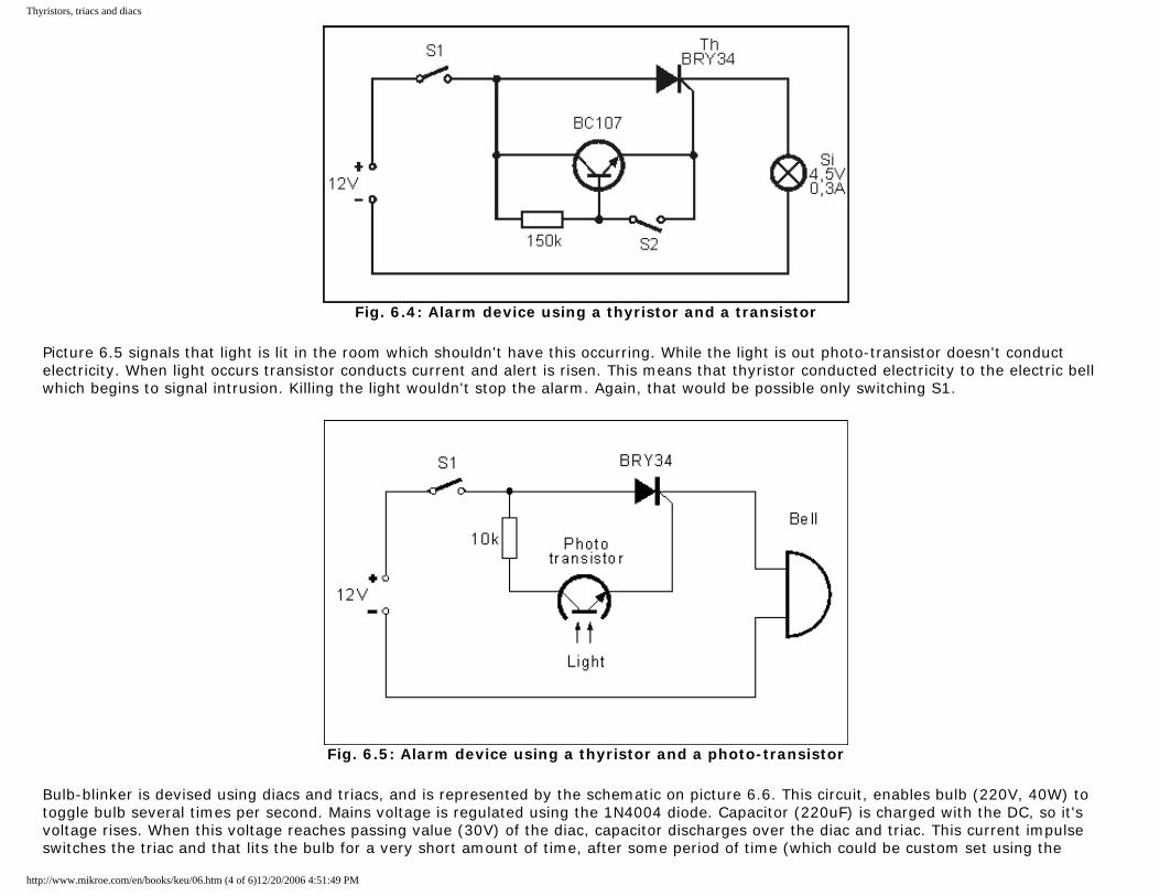
Thyristors, triacs and diacs
Fig. 6.4: Alarm device using a thyristor and a transistor
Picture 6.5 signals that light is lit in the room which shouldn't have this occurring. While the light is out photo-transistor doesn't conduct electricity. When light occurs transistor conducts current and alert is risen. This means that thyristor conducted electricity to the electric bell which begins to signal intrusion. Killing the light wouldn't stop the alarm. Again, that would be possible only switching S1.
Fig. 6.5: Alarm device using a thyristor and a photo-transistor
Bulb-blinker is devised using diacs and triacs, and is represented by the schematic on picture 6.6. This circuit, enables bulb (220V, 40W) to toggle bulb several times per second. Mains voltage is regulated using the 1N4004 diode. Capacitor (220uF) is charged with the DC, so it's voltage rises. When this voltage reaches passing value (30V) of the diac, capacitor discharges over the diac and triac. This current impulse switches the triac and that lits the bulb for a very short amount of time, after some period of time (which could be custom set using the
http://www.mikroe.com/en/books/keu/06.htm (4 of 6)12/20/2006 4:51:49 PM
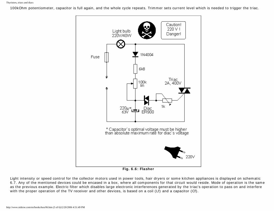
Thyristors, triacs and diacs
100kOhm potentiometer, capacitor is full again, and the whole cycle repeats. Trimmer sets current level which is needed to trigger the triac.
Fig. 6.6: Flasher
Light intensity or speed control for the collector motors used in power tools, hair dryers or some kitchen appliances is displayed on schematic 6.7. Any of the mentioned devices could be encased in a box, where all components for that circuit would reside. Mode of operation is the same as the previous example. Electric filter which disables large electronic interferences generated by the triac's operation to pass on and interfere with the proper operation of the TV receiver and other devices, is based on a coil (Lf) and a capacitor (Cf).
http://www.mikroe.com/en/books/keu/06.htm (5 of 6)12/20/2006 4:51:49 PM
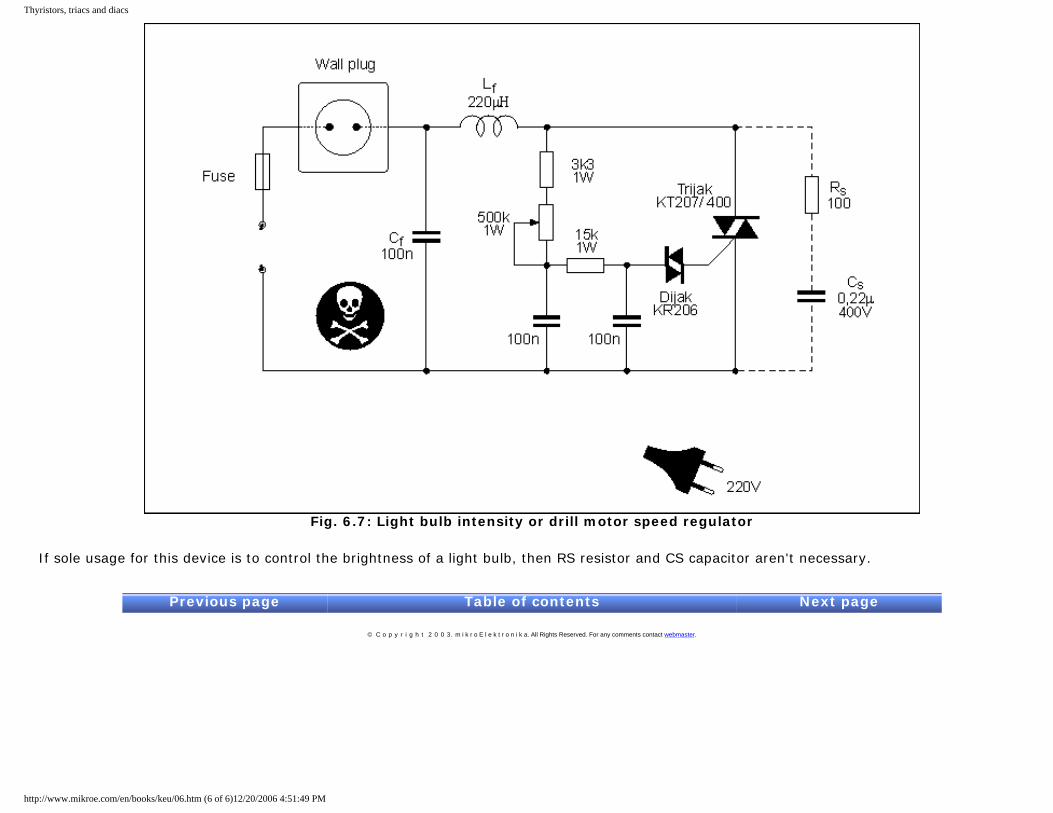
Thyristors, triacs and diacs
Fig. 6.7: Light bulb intensity or drill motor speed regulator
If sole usage for this device is to control the brightness of a light bulb, then RS resistor and CS capacitor aren't necessary.
Previous page Table of contents Next page
© C o p y r i g h t 2 0 0 3. m i k r o E l e k t r o n i k a. All Rights Reserved. For any comments contact webmaster.
http://www.mikroe.com/en/books/keu/06.htm (6 of 6)12/20/2006 4:51:49 PM
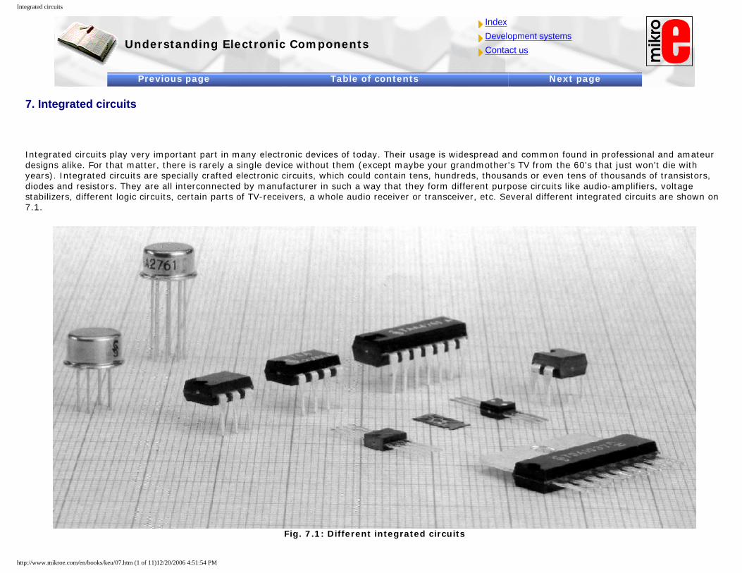
Integrated circuits
Understanding Electronic Components
IndexDevelopment systemsContact us
Previous page Table of contents Next page
7. Integrated circuits
Integrated circuits play very important part in many electronic devices of today. Their usage is widespread and common found in professional and amateur designs alike. For that matter, there is rarely a single device without them (except maybe your grandmother's TV from the 60's that just won't die with years). Integrated circuits are specially crafted electronic circuits, which could contain tens, hundreds, thousands or even tens of thousands of transistors, diodes and resistors. They are all interconnected by manufacturer in such a way that they form different purpose circuits like audio-amplifiers, voltage stabilizers, different logic circuits, certain parts of TV-receivers, a whole audio receiver or transceiver, etc. Several different integrated circuits are shown on 7.1.
Fig. 7.1: Different integrated circuits
http://www.mikroe.com/en/books/keu/07.htm (1 of 11)12/20/2006 4:51:54 PM
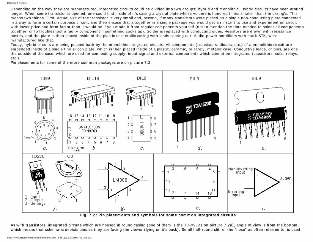
Integrated circuits
Depending on the way they are manufactured, integrated circuits could be divided into two groups: hybrid and monolithic. Hybrid circuits have been around longer. When some transistor is opened, one could find inside of it's casing a crystal plate whose volume is hundred times smaller than the casing's. This means two things. First, actual size of the transistor is very small and, second, if many transistors were placed on a single non-conducting plate connected in a way to form a certain purpose circuit, and then encase that altogether in a single package you would get an instant to use and experiment on circuit with lower price and form factor than it would be if you made it from regular components yourself (not to mention the time needed to solder all components together, or to troubleshoot a faulty component if something cooks up). Solder is replaced with conducting glues. Resistors are drawn with resistance pastes, and the plate is then placed inside of the plastic or metallic casing with leads coming out. Audio-power amplifiers with mark STK, were manufactured like that. Today, hybrid circuits are being pushed back by the monolithic integrated circuits. All components (transistors, diodes, etc.) of a monolithic circuit are embedded inside of a single tiny silicon plate, which is then placed inside of a plastic, ceramic, or rarely, metallic case. Conductive leads, or pins, are one the outside of the case, which are used for connecting supply, input signal and external components which cannot be integrated (capacitors, coils, relays, etc.). Pin placements for some of the more common packages are on picture 7.2:
Fig. 7.2: Pin placements and symbols for some common integrated circuits
As with transistors, integrated circuits which are housed in round casing (one of them is the TO-99, as on picture 7.2a), angle of view is from the bottom, which means that schematic depicts pins as they are facing the viewer (lying on it's back). Small half-round slit, or the "nose" as often referred to, is used
http://www.mikroe.com/en/books/keu/07.htm (2 of 11)12/20/2006 4:51:54 PM

Integrated circuits
as an orientation help. Today, most common found form of an integrated circuit is the chest shaped DIL (DIL16 and DIL8 are shown on pictures 7.2b and 7.2c). Circuit is viewed from the top (where are manufacturer's logo and other marks, like model). Pin counting is circling around the circuit. That means that counting starts from the "nose's" left side, and from the bottom of the right side back to the nose. High power integrated circuits which generate lots of heat are placed in larger cases with the ability for add a heatsink to dissipate the temperature. Examples for those circuits are high power audio-amplifiers with SIL9 case, shown on pictures 7.2d and 7.2e, and the popular DC voltage stabilizer LM713 in two option casings: TO220 and TO3. Symbols used to represent integrated circuits in schematics are on the pictures 7.2g, 7.2h and 7.2i. Symbol is 7.2g is commonly used to represent amplifiers. Different digital and impulse integrated circuits are represented with the 7.2h. Picture 7.2i shows us an important circuit it is an operational amplifier. Signs + and - are representing inverting and non-inverting input line. Signal which is to be amplified is brought between one of the input lines and ground (ground and supply aren't represented, but are mandatory for the circuit to operate). Integrated circuits could be divided in two groups: analog (linear) and digital. Output voltage of linear circuits is continuous, and follows changes in the input. Typical representative of linear circuits is an integrated audio amplifier. When a low frequency source is connected to it's input, microphone for example, voltage on speaker will vary in the same way as voltage from the microphone varies. If watched on an oscilloscope, voltage's signal on the speaker will be the same shape as the mic's signal, only voltage will be higher depending on the amplification of used integrated circuit. It is different situation with digital circuits. Their output voltage, as all other voltages in their circuitry, is not continuous. That voltage could be one of only two possible values: zero, which means that there is zero voltage or one, which is equal to the voltage of the supplying source.
7.1 Analog integrated circuits
While discussing analog circuits, we will look at the LM386 circuit as our example. It has all needed components in single package for a complete audio-amplifier. Picture 7.3a shows an example of an amplifier realized using this integrated circuit, which can be used as a complete low frequency amplifier for a walkman, interphone, cassette player or some other audio device. It could also be used as a test circuit for different experiment and troubleshoot situations. These techniques will be discussed more in forthcoming "Practical ELECTRONICS".
http://www.mikroe.com/en/books/keu/07.htm (3 of 11)12/20/2006 4:51:54 PM
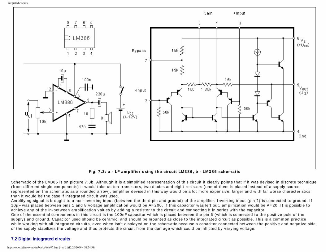
Integrated circuits
Fig. 7.3: a - LF amplifier using the circuit LM386, b - LM386 schematic
Schematic of the LM386 is on picture 7.3b. Although it is a simplified representation of this circuit it clearly points that if it was devised in discrete technique (from different single components) it would take us ten transistors, two diodes and eight resistors (one of them is placed instead of a supply source, represented on the schematic as a rounded arrow), amplifier devised in this way would be a lot more expensive, larger and with far worse characteristics than it would be the case if integrated circuit was used. Amplifying signal is brought to a non-inverting input (between the third pin and ground) of the amplifier. Inverting input (pin 2) is connected to ground. If 10µF was placed between pins 1 and 8 voltage amplification would be A=200. If this capacitor was left out, amplification would be A=20. It is possible to achieve any of the in-between amplification values by adding a resistor to the circuit and connecting it in series with the capacitor. One of the essential components in this circuit is the 100nF capacitor which is placed between the pin 6 (which is connected to the positive pole of the supply) and ground. Capacitor used should be ceramic, and should be mounted as close to the integrated circuit as possible. This is a common practice while working with all integrated circuits, even when isn't displayed on the schematic because a capacitor connected between the positive and negative side of the supply stabilizes the voltage and thus protects the circuit from the damage which could be inflicted by varying voltage.
7.2 Digital integrated circuits
http://www.mikroe.com/en/books/keu/07.htm (4 of 11)12/20/2006 4:51:54 PM
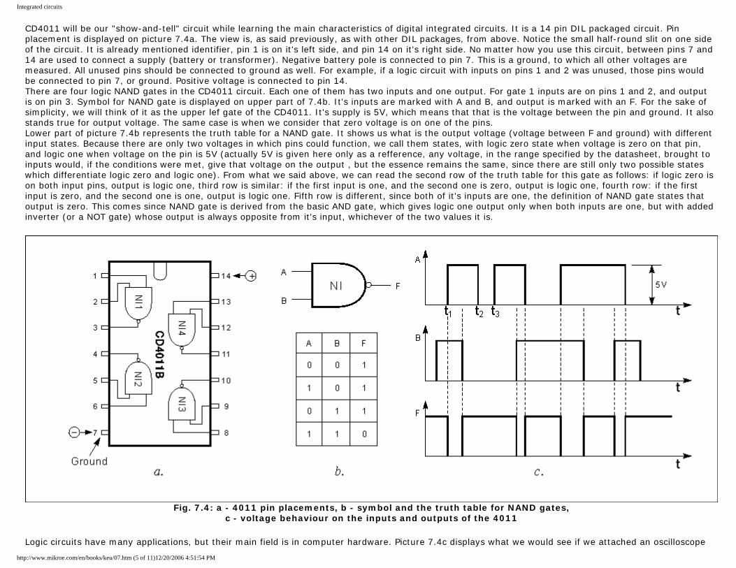
Integrated circuits
CD4011 will be our "show-and-tell" circuit while learning the main characteristics of digital integrated circuits. It is a 14 pin DIL packaged circuit. Pin placement is displayed on picture 7.4a. The view is, as said previously, as with other DIL packages, from above. Notice the small half-round slit on one side of the circuit. It is already mentioned identifier, pin 1 is on it's left side, and pin 14 on it's right side. No matter how you use this circuit, between pins 7 and 14 are used to connect a supply (battery or transformer). Negative battery pole is connected to pin 7. This is a ground, to which all other voltages are measured. All unused pins should be connected to ground as well. For example, if a logic circuit with inputs on pins 1 and 2 was unused, those pins would be connected to pin 7, or ground. Positive voltage is connected to pin 14. There are four logic NAND gates in the CD4011 circuit. Each one of them has two inputs and one output. For gate 1 inputs are on pins 1 and 2, and output is on pin 3. Symbol for NAND gate is displayed on upper part of 7.4b. It's inputs are marked with A and B, and output is marked with an F. For the sake of simplicity, we will think of it as the upper lef gate of the CD4011. It's supply is 5V, which means that that is the voltage between the pin and ground. It also stands true for output voltage. The same case is when we consider that zero voltage is on one of the pins. Lower part of picture 7.4b represents the truth table for a NAND gate. It shows us what is the output voltage (voltage between F and ground) with different input states. Because there are only two voltages in which pins could function, we call them states, with logic zero state when voltage is zero on that pin, and logic one when voltage on the pin is 5V (actually 5V is given here only as a refference, any voltage, in the range specified by the datasheet, brought to inputs would, if the conditions were met, give that voltage on the output , but the essence remains the same, since there are still only two possible states which differentiate logic zero and logic one). From what we said above, we can read the second row of the truth table for this gate as follows: if logic zero is on both input pins, output is logic one, third row is similar: if the first input is one, and the second one is zero, output is logic one, fourth row: if the first input is zero, and the second one is one, output is logic one. Fifth row is different, since both of it's inputs are one, the definition of NAND gate states that output is zero. This comes since NAND gate is derived from the basic AND gate, which gives logic one output only when both inputs are one, but with added inverter (or a NOT gate) whose output is always opposite from it's input, whichever of the two values it is.
Fig. 7.4: a - 4011 pin placements, b - symbol and the truth table for NAND gates,
c - voltage behaviour on the inputs and outputs of the 4011
Logic circuits have many applications, but their main field is in computer hardware. Picture 7.4c displays what we would see if we attached an oscilloscope
http://www.mikroe.com/en/books/keu/07.htm (5 of 11)12/20/2006 4:51:54 PM
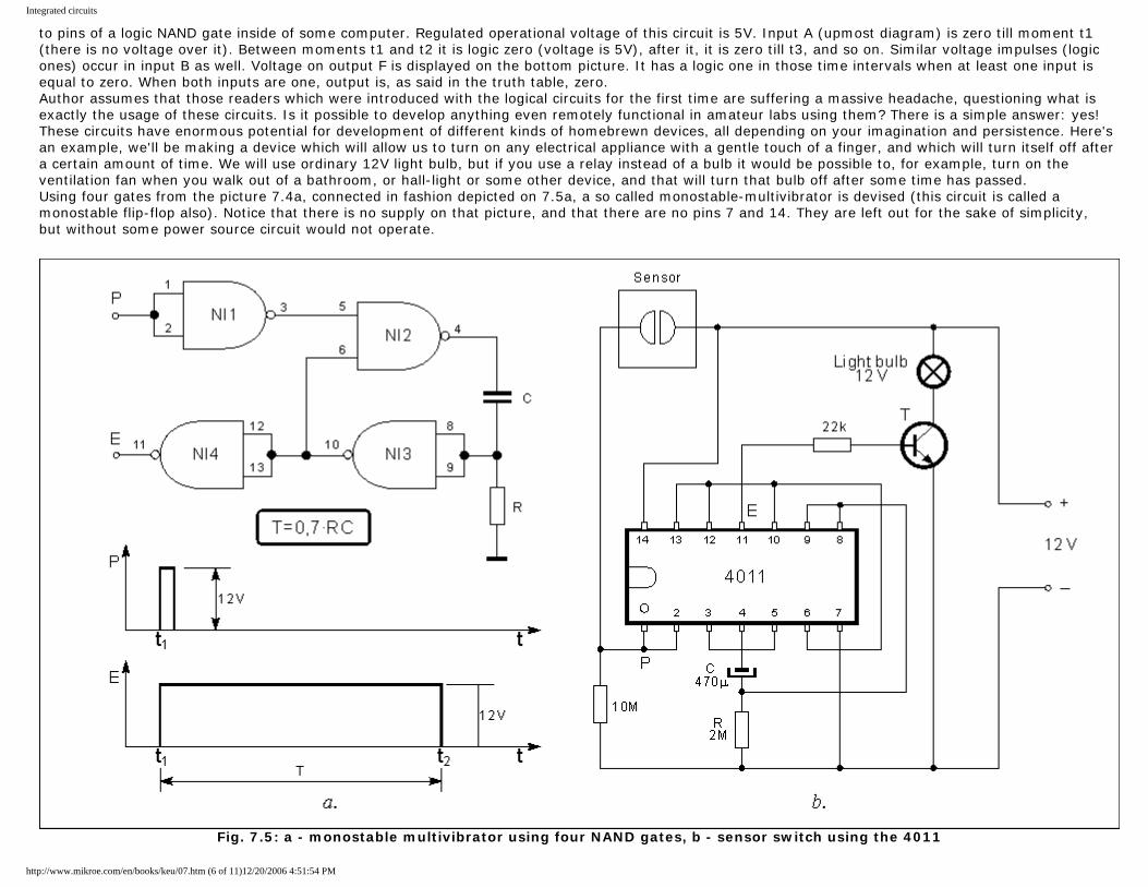
Integrated circuits
to pins of a logic NAND gate inside of some computer. Regulated operational voltage of this circuit is 5V. Input A (upmost diagram) is zero till moment t1 (there is no voltage over it). Between moments t1 and t2 it is logic zero (voltage is 5V), after it, it is zero till t3, and so on. Similar voltage impulses (logic ones) occur in input B as well. Voltage on output F is displayed on the bottom picture. It has a logic one in those time intervals when at least one input is equal to zero. When both inputs are one, output is, as said in the truth table, zero. Author assumes that those readers which were introduced with the logical circuits for the first time are suffering a massive headache, questioning what is exactly the usage of these circuits. Is it possible to develop anything even remotely functional in amateur labs using them? There is a simple answer: yes! These circuits have enormous potential for development of different kinds of homebrewn devices, all depending on your imagination and persistence. Here's an example, we'll be making a device which will allow us to turn on any electrical appliance with a gentle touch of a finger, and which will turn itself off after a certain amount of time. We will use ordinary 12V light bulb, but if you use a relay instead of a bulb it would be possible to, for example, turn on the ventilation fan when you walk out of a bathroom, or hall-light or some other device, and that will turn that bulb off after some time has passed. Using four gates from the picture 7.4a, connected in fashion depicted on 7.5a, a so called monostable-multivibrator is devised (this circuit is called a monostable flip-flop also). Notice that there is no supply on that picture, and that there are no pins 7 and 14. They are left out for the sake of simplicity, but without some power source circuit would not operate.
Fig. 7.5: a - monostable multivibrator using four NAND gates, b - sensor switch using the 4011
http://www.mikroe.com/en/books/keu/07.htm (6 of 11)12/20/2006 4:51:54 PM
Integrated circuits
Lets dig into the functionalities of this circuit. Both inputs of NAND1 are connected to each other, so when input P occurs, output is zero. This logic zero is passed on to NAND2, so no matter what is on the input 6, output 4 is logic one. This means that, between the ground and pin, voltage is equal to 12V. Current flows through capacitor C and resistor R, so capacitor begins to fill. Every empty capacitor behaves like a short circuit. Because of that, when 12V appears on the pin, it is also present on the resistor R. It is a voltage between it's upper end and ground, and that also means with the connected pins 8 and 9. Pin 10 shows logic zero because of this which is connected to pin 6. From now on, logic zero on pin 5 is no longer needed because only one input needs to be zero for output to be logic one. So input P is no longer needed as well. Gates NAND2 and NAND3 are self sufficiently maintaining logic zero on pin 4. How long will this last? It depends on the capacitance of the capacitor and on the resistance of the resistor. As capacitor is filled, voltage on resistor rises so the current and voltage drop. When this voltage drops to 1/2 of the supply voltage (6V in our case), NAND3 detects zero on it's inputs, and so logic one appears on pin 10. Since logic one is now on input 5 (no logic one present on P), and on input 6, output 4 is zero, capacitor dumps it's charge, and the circuit starts operating again. As we saw, for a certain period of time, which is equal to T=0.7*RC output of pin 10 was logic zero. During that time output E (pin 11) is logic one. For example, if R = 2M? and C=47µF, for time T = 2*10^6*47*10^-6 = 94 s from the moment impulse on input P subsided, voltage on output E is 12V. End result of our experiment is on picture 7.5a. Short positive impulse appearing on P in the moment t1 caused a rather longer lasting variable impulse on output E. Schematic on 7.5b displays this circuit which allows us to light a bulb using four NAND gates interconnected in the way shown on picture 7.5a. Sensor itself is devised using two copper (or some other conducting material) plates glued to some nonconducting material (plastics, wood, etc.) in close proximity between each other. So, when we touch with a tip of our finger and by that connecting two plates, we close the circuit, 12V appear on input P, which in return conducts that voltage to the output E, resistor R = 22kO conducts base current and bulb lights. When we remove our finger, output E will last for 94 seconds, after which it goes to logic zero and the light goes out. Transistor T is selected so that it's maximum allowed collector current is higher than the current of a light bulb. (Light bulb's current flow value is acquired by dividing it's power with it's voltage. For example, if it's power is P = 6W and voltage is U = 12V, current through the bulb is I = P/U = 6W/12V = 0.5A or higher.
7.3 Practical examples
Interesting and useful applications, which would demonstrate properly all possiblities and broad usage of these electronic components are too much of a scope than could be addressed by this book. So, we will demonstrate another three circuits, and some others will be covered in some future issues. Picture 7.6 shows electric schematic for a stereo audio-amp using TDA4935. It is a modern integrated circuit with two independent low frequency amplifiers with a pre-amp, supply stage and an output stage. Left and right low frequency signals are marked with UL and UD, which are brought to two inputs of the amplifier. Beside the amp, circuit also has a built-in heat and overload protection. Maximum output power for each of these amplifiers is 15W, so they can be used in stereo devices of 2x15W output power. There is a possibility for these amplifiers to be connected as a bridge, to facilitate a 30W mono amp. That schematic as well as explanations, it's characteristics and practical usage you'll find out in future issues of "Practical ELECTRONICS".
http://www.mikroe.com/en/books/keu/07.htm (7 of 11)12/20/2006 4:51:54 PM
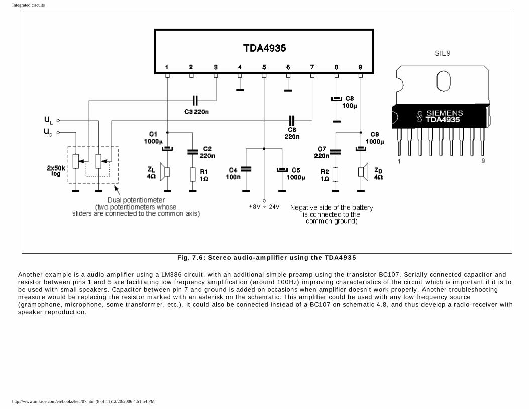
Integrated circuits
Fig. 7.6: Stereo audio-amplifier using the TDA4935
Another example is a audio amplifier using a LM386 circuit, with an additional simple preamp using the transistor BC107. Serially connected capacitor and resistor between pins 1 and 5 are facilitating low frequency amplification (around 100Hz) improving characteristics of the circuit which is important if it is to be used with small speakers. Capacitor between pin 7 and ground is added on occasions when amplifier doesn't work properly. Another troubleshooting measure would be replacing the resistor marked with an asterisk on the schematic. This amplifier could be used with any low frequency source (gramophone, microphone, some transformer, etc.), it could also be connected instead of a BC107 on schematic 4.8, and thus develop a radio-receiver with speaker reproduction.
http://www.mikroe.com/en/books/keu/07.htm (8 of 11)12/20/2006 4:51:54 PM
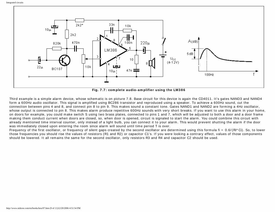
Integrated circuits
Fig. 7.7: complete audio-amplifier using the LM386
Third example is a simple alarm device, whose schematic is on picture 7.8. Base circuit for this device is again the CD4011. It's gates NAND3 and NAND4 form a 600Hz audio oscillator. This signal is amplified using BC286 transistor and reproduced using a speaker. To achieve a 600Hz sound, cut the connection between pins 4 and 8, and connect pin 8 to pin 9. This makes sound a constant tone. Gates NAND1 and NAND2 are forming a 4Hz oscillator, whose output is connected to pin 8. This makes alarm produce repetitive 600Hz sounds with very short breaks. If you want to use this alarm in your home, on doors for example, you could make switch S using two brass plates, connected to pins 1 and 7, which will be adjusted to both a door and a door frame making them conduct current when doors are closed, so, when door is opened, circuit is signaled to start the alarm. You could combine this circuit with already mentioned time interval counter, only instead of a light bulb, you can connect it to your alarm. This would prevent shutting the alarm if the door was immediately closed upon entering the room since alarm will sound until time period T is over. Frequency of the first oscillator, or frequency of silent gaps created by the second oscillator are determined using this formula fi = 0.6/(Ri*Ci). So, to lower those frequencies you should rise the values of resistors (R1 and R2) or capacitor C1's. If you were looking a contrary effect, values of those components should be lowered. It all remains the same for the second oscillator, only resistors R3 and R4 and capacitor C2 should be used.
http://www.mikroe.com/en/books/keu/07.htm (9 of 11)12/20/2006 4:51:54 PM
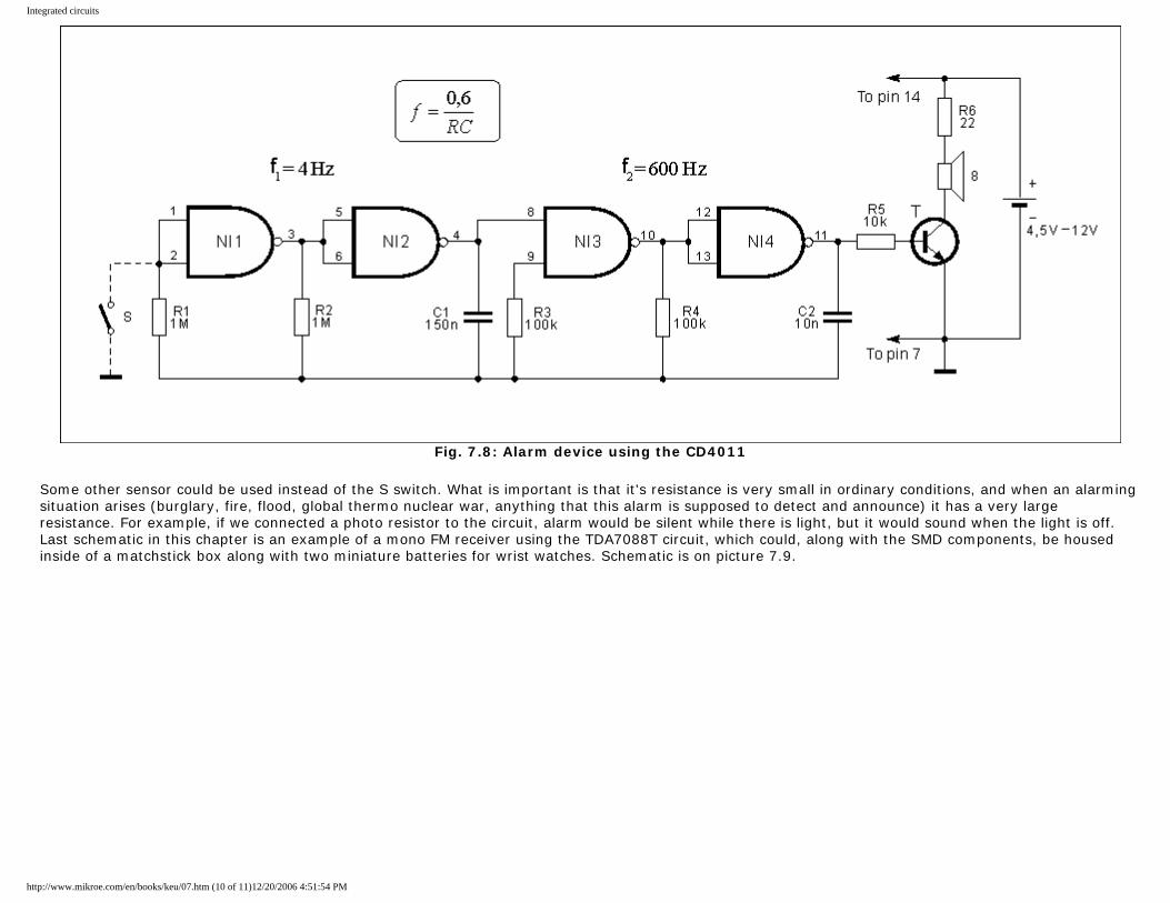
Integrated circuits
Fig. 7.8: Alarm device using the CD4011
Some other sensor could be used instead of the S switch. What is important is that it's resistance is very small in ordinary conditions, and when an alarming situation arises (burglary, fire, flood, global thermo nuclear war, anything that this alarm is supposed to detect and announce) it has a very large resistance. For example, if we connected a photo resistor to the circuit, alarm would be silent while there is light, but it would sound when the light is off. Last schematic in this chapter is an example of a mono FM receiver using the TDA7088T circuit, which could, along with the SMD components, be housed inside of a matchstick box along with two miniature batteries for wrist watches. Schematic is on picture 7.9.
http://www.mikroe.com/en/books/keu/07.htm (10 of 11)12/20/2006 4:51:54 PM
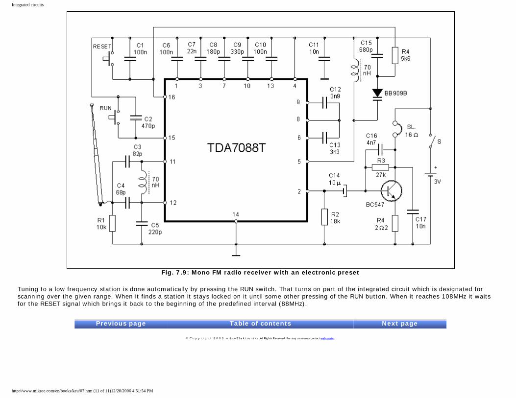
Integrated circuits
Fig. 7.9: Mono FM radio receiver with an electronic preset
Tuning to a low frequency station is done automatically by pressing the RUN switch. That turns on part of the integrated circuit which is designated for scanning over the given range. When it finds a station it stays locked on it until some other pressing of the RUN button. When it reaches 108MHz it waits for the RESET signal which brings it back to the beginning of the predefined interval (88MHz).
Previous page Table of contents Next page
© C o p y r i g h t 2 0 0 3. m i k r o E l e k t r o n i k a. All Rights Reserved. For any comments contact webmaster.
http://www.mikroe.com/en/books/keu/07.htm (11 of 11)12/20/2006 4:51:54 PM
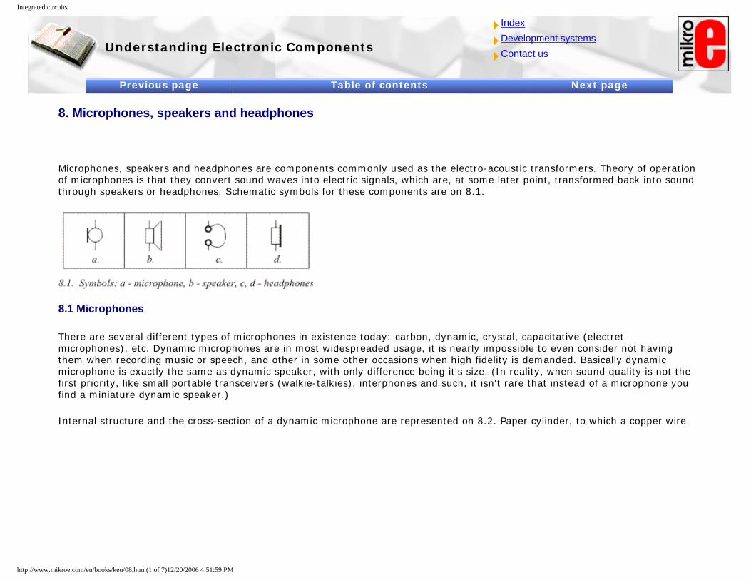
Integrated circuits
Understanding Electronic Components
IndexDevelopment systemsContact us
Previous page Table of contents Next page
8. Microphones, speakers and headphones
Microphones, speakers and headphones are components commonly used as the electro-acoustic transformers. Theory of operation of microphones is that they convert sound waves into electric signals, which are, at some later point, transformed back into sound through speakers or headphones. Schematic symbols for these components are on 8.1.
8.1 Microphones
There are several different types of microphones in existence today: carbon, dynamic, crystal, capacitative (electret microphones), etc. Dynamic microphones are in most widespreaded usage, it is nearly impossible to even consider not having them when recording music or speech, and other in some other occasions when high fidelity is demanded. Basically dynamic microphone is exactly the same as dynamic speaker, with only difference being it's size. (In reality, when sound quality is not the first priority, like small portable transceivers (walkie-talkies), interphones and such, it isn't rare that instead of a microphone you find a miniature dynamic speaker.)
Internal structure and the cross-section of a dynamic microphone are represented on 8.2. Paper cylinder, to which a copper wire
http://www.mikroe.com/en/books/keu/08.htm (1 of 7)12/20/2006 4:51:59 PM
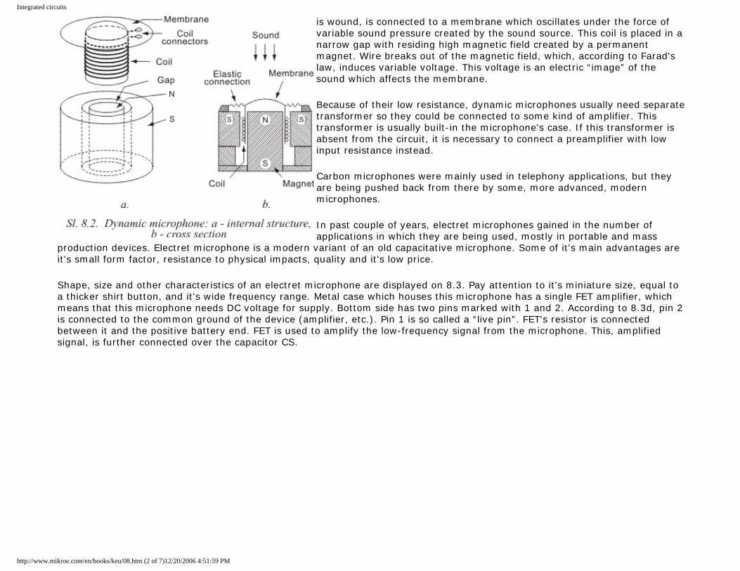
Integrated circuits
is wound, is connected to a membrane which oscillates under the force of variable sound pressure created by the sound source. This coil is placed in a narrow gap with residing high magnetic field created by a permanent magnet. Wire breaks out of the magnetic field, which, according to Farad's law, induces variable voltage. This voltage is an electric “image” of the sound which affects the membrane.
Because of their low resistance, dynamic microphones usually need separate transformer so they could be connected to some kind of amplifier. This transformer is usually built-in the microphone's case. If this transformer is absent from the circuit, it is necessary to connect a preamplifier with low input resistance instead.
Carbon microphones were mainly used in telephony applications, but they are being pushed back from there by some, more advanced, modern microphones.
In past couple of years, electret microphones gained in the number of applications in which they are being used, mostly in portable and mass
production devices. Electret microphone is a modern variant of an old capacitative microphone. Some of it's main advantages are it's small form factor, resistance to physical impacts, quality and it's low price.
Shape, size and other characteristics of an electret microphone are displayed on 8.3. Pay attention to it's miniature size, equal to a thicker shirt button, and it's wide frequency range. Metal case which houses this microphone has a single FET amplifier, which means that this microphone needs DC voltage for supply. Bottom side has two pins marked with 1 and 2. According to 8.3d, pin 2 is connected to the common ground of the device (amplifier, etc.). Pin 1 is so called a “live pin”. FET's resistor is connected between it and the positive battery end. FET is used to amplify the low-frequency signal from the microphone. This, amplified signal, is further connected over the capacitor CS.
http://www.mikroe.com/en/books/keu/08.htm (2 of 7)12/20/2006 4:51:59 PM
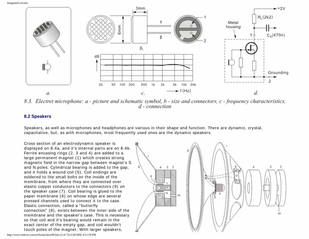
Integrated circuits
8.2 Speakers
Speakers, as well as microphones and headphones are various in their shape and function. There are dynamic, crystal, capacitative, but, as with microphones, most frequently used ones are the dynamic speakers.
Cross section of an electrodynamic speaker is displayed on 8.4a, and it's internal parts are on 8.4b. Ferrite encasing rings (2, 3 and 4) are added to a large permanent magnet (1) which creates strong magnetic field in the narrow gap between magnet's S and N poles. Cylindrical bearing is added to the gap, and it holds a wound coil (5). Coil endings are soldered to the small bolts on the inside of the membrane, from where they are connected over elastic copper conductors to the connectors (9) on the speaker case (7). Coil bearing is glued to the paper membrane (6) on whose edge are several pressed channels used to connect it to the case. Elastic connection, called a “butterfly connection” (8), exists between the inner side of the membrane and the speaker's case. This is necessary so that coil and it's bearing would remain in the exact center of the empty gap, and coil wouldn't touch poles of the magnet. With larger speakers,
http://www.mikroe.com/en/books/keu/08.htm (3 of 7)12/20/2006 4:51:59 PM
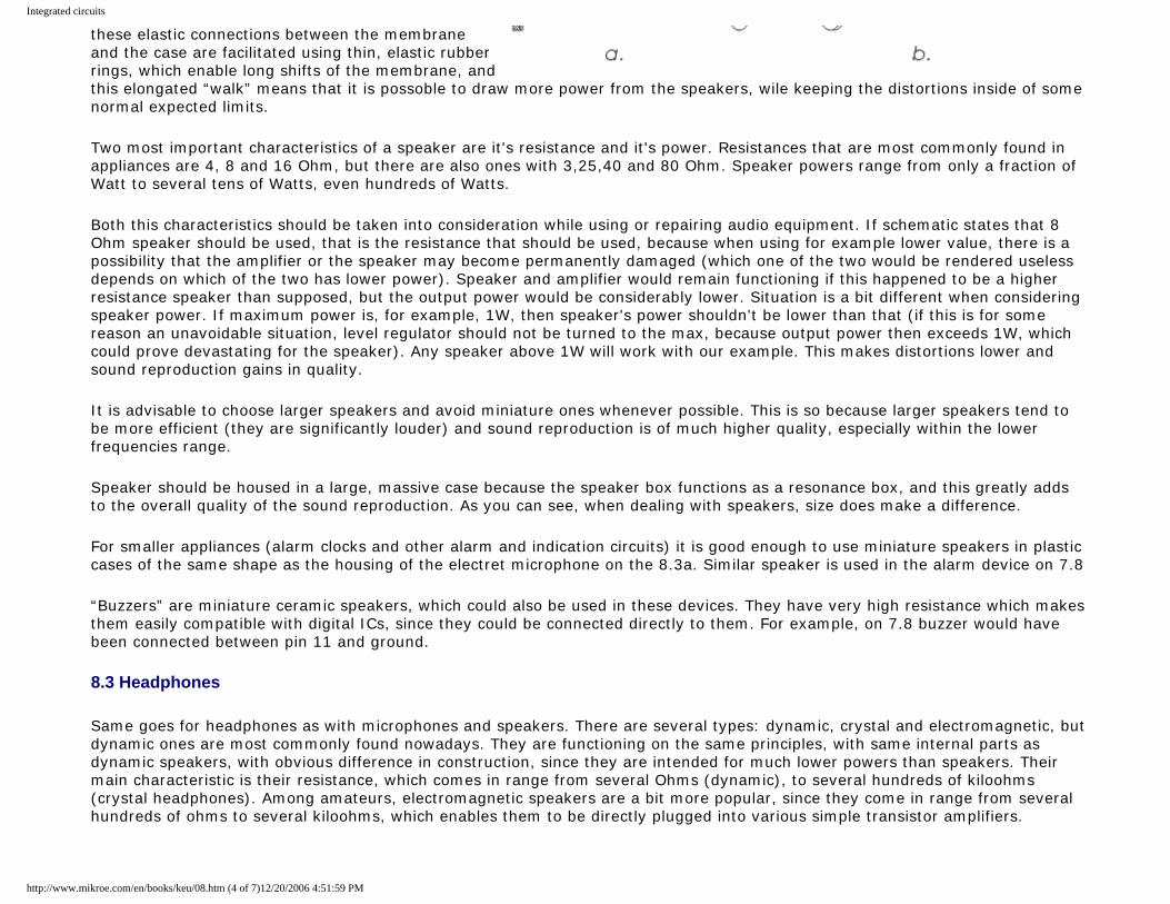
Integrated circuits
these elastic connections between the membrane and the case are facilitated using thin, elastic rubber rings, which enable long shifts of the membrane, and this elongated “walk” means that it is possoble to draw more power from the speakers, wile keeping the distortions inside of some normal expected limits.
Two most important characteristics of a speaker are it's resistance and it's power. Resistances that are most commonly found in appliances are 4, 8 and 16 Ohm, but there are also ones with 3,25,40 and 80 Ohm. Speaker powers range from only a fraction of Watt to several tens of Watts, even hundreds of Watts.
Both this characteristics should be taken into consideration while using or repairing audio equipment. If schematic states that 8 Ohm speaker should be used, that is the resistance that should be used, because when using for example lower value, there is a possibility that the amplifier or the speaker may become permanently damaged (which one of the two would be rendered useless depends on which of the two has lower power). Speaker and amplifier would remain functioning if this happened to be a higher resistance speaker than supposed, but the output power would be considerably lower. Situation is a bit different when considering speaker power. If maximum power is, for example, 1W, then speaker's power shouldn't be lower than that (if this is for some reason an unavoidable situation, level regulator should not be turned to the max, because output power then exceeds 1W, which could prove devastating for the speaker). Any speaker above 1W will work with our example. This makes distortions lower and sound reproduction gains in quality.
It is advisable to choose larger speakers and avoid miniature ones whenever possible. This is so because larger speakers tend to be more efficient (they are significantly louder) and sound reproduction is of much higher quality, especially within the lower frequencies range.
Speaker should be housed in a large, massive case because the speaker box functions as a resonance box, and this greatly adds to the overall quality of the sound reproduction. As you can see, when dealing with speakers, size does make a difference.
For smaller appliances (alarm clocks and other alarm and indication circuits) it is good enough to use miniature speakers in plastic cases of the same shape as the housing of the electret microphone on the 8.3a. Similar speaker is used in the alarm device on 7.8
“Buzzers” are miniature ceramic speakers, which could also be used in these devices. They have very high resistance which makes them easily compatible with digital ICs, since they could be connected directly to them. For example, on 7.8 buzzer would have been connected between pin 11 and ground.
8.3 Headphones
Same goes for headphones as with microphones and speakers. There are several types: dynamic, crystal and electromagnetic, but dynamic ones are most commonly found nowadays. They are functioning on the same principles, with same internal parts as dynamic speakers, with obvious difference in construction, since they are intended for much lower powers than speakers. Their main characteristic is their resistance, which comes in range from several Ohms (dynamic), to several hundreds of kiloohms (crystal headphones). Among amateurs, electromagnetic speakers are a bit more popular, since they come in range from several hundreds of ohms to several kiloohms, which enables them to be directly plugged into various simple transistor amplifiers.
http://www.mikroe.com/en/books/keu/08.htm (4 of 7)12/20/2006 4:51:59 PM
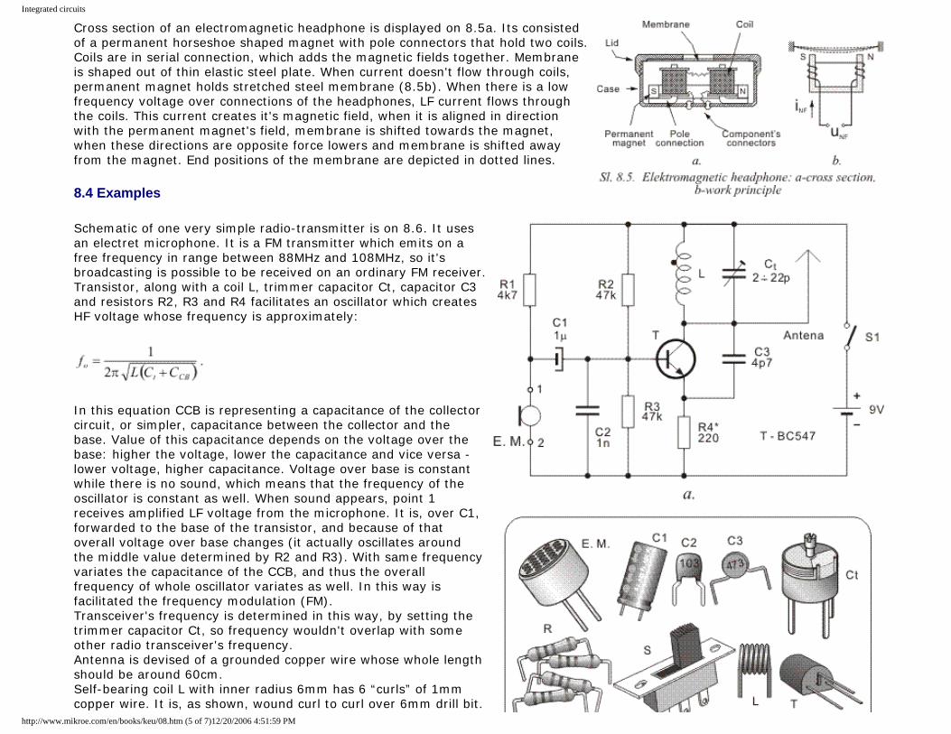
Integrated circuits
Cross section of an electromagnetic headphone is displayed on 8.5a. Its consisted of a permanent horseshoe shaped magnet with pole connectors that hold two coils. Coils are in serial connection, which adds the magnetic fields together. Membrane is shaped out of thin elastic steel plate. When current doesn't flow through coils, permanent magnet holds stretched steel membrane (8.5b). When there is a low frequency voltage over connections of the headphones, LF current flows through the coils. This current creates it's magnetic field, when it is aligned in direction with the permanent magnet's field, membrane is shifted towards the magnet, when these directions are opposite force lowers and membrane is shifted away from the magnet. End positions of the membrane are depicted in dotted lines.
8.4 Examples
Schematic of one very simple radio-transmitter is on 8.6. It uses an electret microphone. It is a FM transmitter which emits on a free frequency in range between 88MHz and 108MHz, so it's broadcasting is possible to be received on an ordinary FM receiver. Transistor, along with a coil L, trimmer capacitor Ct, capacitor C3 and resistors R2, R3 and R4 facilitates an oscillator which creates HF voltage whose frequency is approximately:
In this equation CCB is representing a capacitance of the collector circuit, or simpler, capacitance between the collector and the base. Value of this capacitance depends on the voltage over the base: higher the voltage, lower the capacitance and vice versa - lower voltage, higher capacitance. Voltage over base is constant while there is no sound, which means that the frequency of the oscillator is constant as well. When sound appears, point 1 receives amplified LF voltage from the microphone. It is, over C1, forwarded to the base of the transistor, and because of that overall voltage over base changes (it actually oscillates around the middle value determined by R2 and R3). With same frequency variates the capacitance of the CCB, and thus the overall frequency of whole oscillator variates as well. In this way is facilitated the frequency modulation (FM). Transceiver's frequency is determined in this way, by setting the trimmer capacitor Ct, so frequency wouldn't overlap with some other radio transceiver's frequency. Antenna is devised of a grounded copper wire whose whole length should be around 60cm. Self-bearing coil L with inner radius 6mm has 6 “curls” of 1mm copper wire. It is, as shown, wound curl to curl over 6mm drill bit.
http://www.mikroe.com/en/books/keu/08.htm (5 of 7)12/20/2006 4:51:59 PM
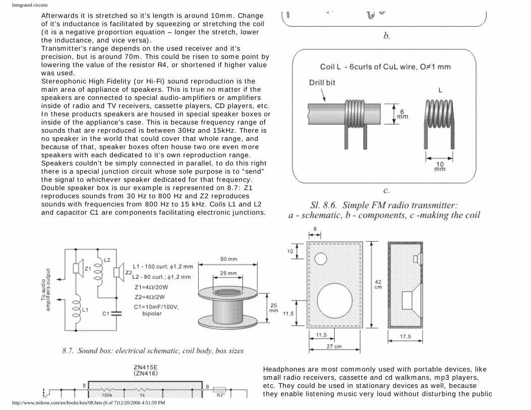
Integrated circuits
Afterwards it is stretched so it's length is around 10mm. Change of it's inductance is facilitated by squeezing or stretching the coil (it is a negative proportion equation – longer the stretch, lower the inductance, and vice versa). Transmitter's range depends on the used receiver and it's precision, but is around 70m. This could be risen to some point by lowering the value of the resistor R4, or shortened if higher value was used. Stereophonic High Fidelity (or Hi-Fi) sound reproduction is the main area of appliance of speakers. This is true no matter if the speakers are connected to special audio-amplifiers or amplifiers inside of radio and TV receivers, cassette players, CD players, etc. In these products speakers are housed in special speaker boxes or inside of the appliance's case. This is because frequency range of sounds that are reproduced is between 30Hz and 15kHz. There is no speaker in the world that could cover that whole range, and because of that, speaker boxes often house two ore even more speakers with each dedicated to it's own reproduction range. Speakers couldn't be simply connected in parallel, to do this right there is a special junction circuit whose sole purpose is to “send” the signal to whichever speaker dedicated for that frequency. Double speaker box is our example is represented on 8.7: Z1 reproduces sounds from 30 Hz to 800 Hz and Z2 reproduces sounds with frequencies from 800 Hz to 15 kHz. Coils L1 and L2 and capacitor C1 are components facilitating electronic junctions.
Headphones are most commonly used with portable devices, like small radio receivers, cassette and cd walkmans, mp3 players, etc. They could be used in stationary devices as well, because they enable listening music very loud without disturbing the public
http://www.mikroe.com/en/books/keu/08.htm (6 of 7)12/20/2006 4:51:59 PM
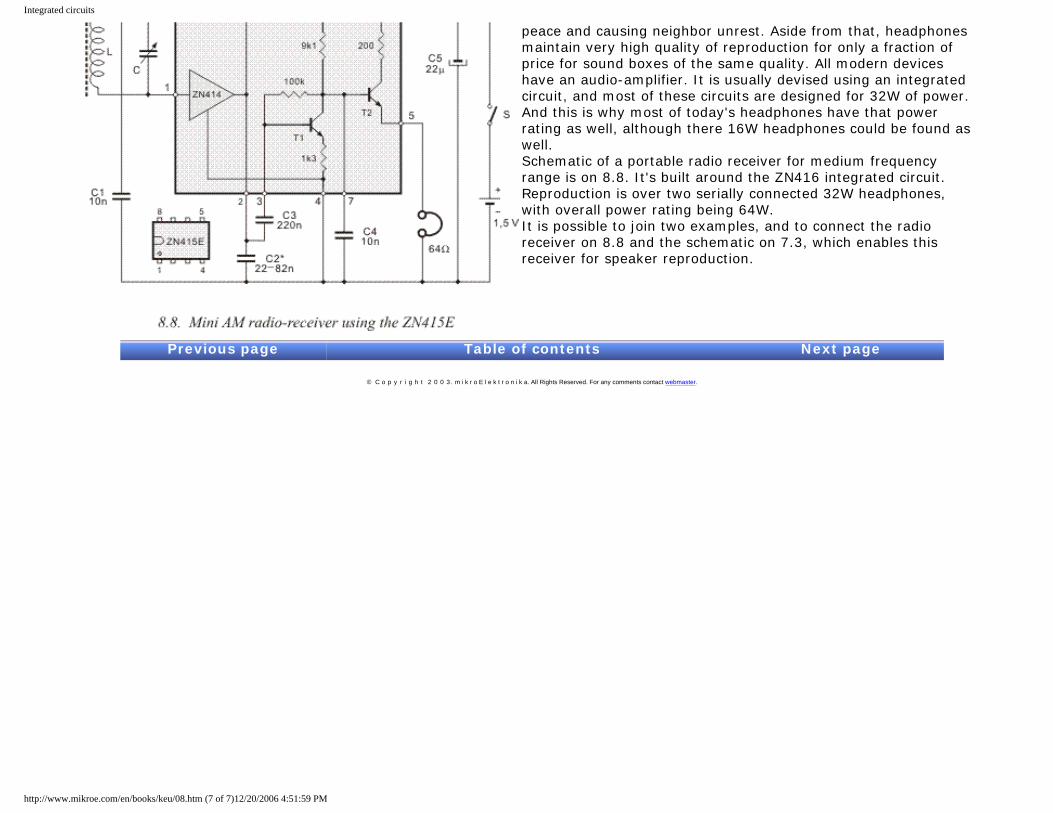
Integrated circuits
peace and causing neighbor unrest. Aside from that, headphones maintain very high quality of reproduction for only a fraction of price for sound boxes of the same quality. All modern devices have an audio-amplifier. It is usually devised using an integrated circuit, and most of these circuits are designed for 32W of power. And this is why most of today's headphones have that power rating as well, although there 16W headphones could be found as well. Schematic of a portable radio receiver for medium frequency range is on 8.8. It's built around the ZN416 integrated circuit. Reproduction is over two serially connected 32W headphones, with overall power rating being 64W. It is possible to join two examples, and to connect the radio receiver on 8.8 and the schematic on 7.3, which enables this receiver for speaker reproduction.
Previous page Table of contents Next page
© C o p y r i g h t 2 0 0 3. m i k r o E l e k t r o n i k a. All Rights Reserved. For any comments contact webmaster.
http://www.mikroe.com/en/books/keu/08.htm (7 of 7)12/20/2006 4:51:59 PM
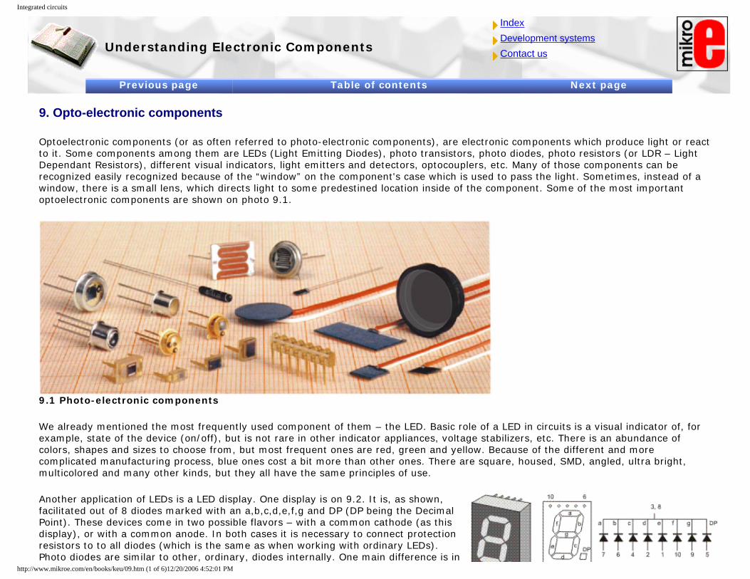
Integrated circuits
Understanding Electronic Components
IndexDevelopment systemsContact us
Previous page Table of contents Next page
9. Opto-electronic components
Optoelectronic components (or as often referred to photo-electronic components), are electronic components which produce light or react to it. Some components among them are LEDs (Light Emitting Diodes), photo transistors, photo diodes, photo resistors (or LDR – Light Dependant Resistors), different visual indicators, light emitters and detectors, optocouplers, etc. Many of those components can be recognized easily recognized because of the “window” on the component's case which is used to pass the light. Sometimes, instead of a window, there is a small lens, which directs light to some predestined location inside of the component. Some of the most important optoelectronic components are shown on photo 9.1.
9.1 Photo-electronic components
We already mentioned the most frequently used component of them – the LED. Basic role of a LED in circuits is a visual indicator of, for example, state of the device (on/off), but is not rare in other indicator appliances, voltage stabilizers, etc. There is an abundance of colors, shapes and sizes to choose from, but most frequent ones are red, green and yellow. Because of the different and more complicated manufacturing process, blue ones cost a bit more than other ones. There are square, housed, SMD, angled, ultra bright, multicolored and many other kinds, but they all have the same principles of use.
Another application of LEDs is a LED display. One display is on 9.2. It is, as shown, facilitated out of 8 diodes marked with an a,b,c,d,e,f,g and DP (DP being the Decimal Point). These devices come in two possible flavors – with a common cathode (as this display), or with a common anode. In both cases it is necessary to connect protection resistors to to all diodes (which is the same as when working with ordinary LEDs). Photo diodes are similar to other, ordinary, diodes internally. One main difference is in
http://www.mikroe.com/en/books/keu/09.htm (1 of 6)12/20/2006 4:52:01 PM
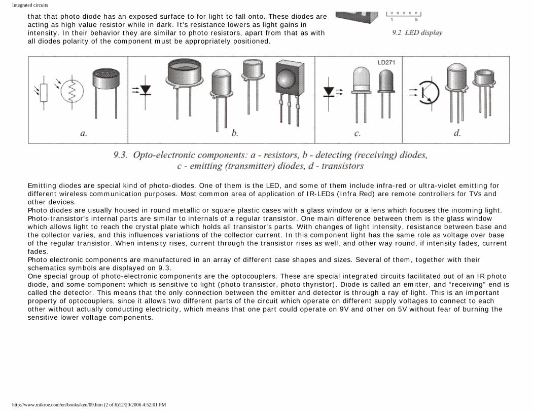
Integrated circuits
that that photo diode has an exposed surface to for light to fall onto. These diodes are acting as high value resistor while in dark. It's resistance lowers as light gains in intensity. In their behavior they are similar to photo resistors, apart from that as with all diodes polarity of the component must be appropriately positioned.
Emitting diodes are special kind of photo-diodes. One of them is the LED, and some of them include infra-red or ultra-violet emitting for different wireless communication purposes. Most common area of application of IR-LEDs (Infra Red) are remote controllers for TVs and other devices. Photo diodes are usually housed in round metallic or square plastic cases with a glass window or a lens which focuses the incoming light. Photo-transistor's internal parts are similar to internals of a regular transistor. One main difference between them is the glass window which allows light to reach the crystal plate which holds all transistor's parts. With changes of light intensity, resistance between base and the collector varies, and this influences variations of the collector current. In this component light has the same role as voltage over base of the regular transistor. When intensity rises, current through the transistor rises as well, and other way round, if intensity fades, current fades. Photo electronic components are manufactured in an array of different case shapes and sizes. Several of them, together with their schematics symbols are displayed on 9.3. One special group of photo-electronic components are the optocouplers. These are special integrated circuits facilitated out of an IR photo diode, and some component which is sensitive to light (photo transistor, photo thyristor). Diode is called an emitter, and “receiving” end is called the detector. This means that the only connection between the emitter and detector is through a ray of light. This is an important property of optocouplers, since it allows two different parts of the circuit which operate on different supply voltages to connect to each other without actually conducting electricity, which means that one part could operate on 9V and other on 5V without fear of burning the sensitive lower voltage components.
http://www.mikroe.com/en/books/keu/09.htm (2 of 6)12/20/2006 4:52:01 PM
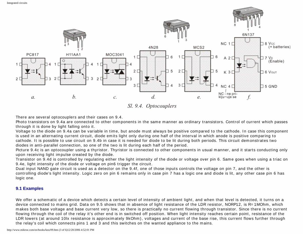
Integrated circuits
There are several optocouplers and their cases on 9.4. Photo transistors on 9.4a are connected to other components in the same manner as ordinary transistors. Control of current which passes through it is done by light falling onto it. Voltage to the diode on 9.4a can be variable in time, but anode must always be positive compared to the cathode. In case this component is used in an alternating current circuit, diode emits light only during one half of the interval in which anode is positive comparing to cathode. It is possible to use circuit on 9.4b in case it is needed for diode to be lit during both periods. This circuit demonstrates two diodes in anti-parallel connection, so one of the two is lit during each half of the period. Picture 9.4c is an optocoupler using a thyristor. Thyristor is connected to other components in usual manner, and it starts conducting only upon receiving light impulse created by the diode. Transistor on 9.4d is controlled by regulating either the light intensity of the diode or voltage over pin 6. Same goes when using a triac on 9.4e, light intensity of the diode or voltage on pin6 trigger the circuit. Dual input NAND gate circuit is used as a detector on the 9.4f, one of those inputs controls the voltage on pin 7, and the other is controlling diode's light intensity. Logic zero on pin 6 remains only in case pin 7 has a logic one and diode is lit, any other case pin 6 has logic one.
9.1 Examples
We offer a schematic of a device which detects a certain level of intensity of ambient light, and when that level is detected, it turns on a device connected to mains grid. Data on 9.5 shows that in absence of light resistance of the LDR resistor, NORP12, is R=1MOhm, which makes both base voltage and base current very low, so there is practically no current flowing through transistor. Since there is no current flowing through the coil of the relay it's other end is in switched off position. When light intensity reaches certain point, resistance of the LDR lowers (at around 10lx resistance is approximately 9kOhm), voltages and current of the base rise, this current flows further through the relay's coil which connects pins 1 and 3 and this switches on the wanted appliance to the mains.
http://www.mikroe.com/en/books/keu/09.htm (3 of 6)12/20/2006 4:52:01 PM
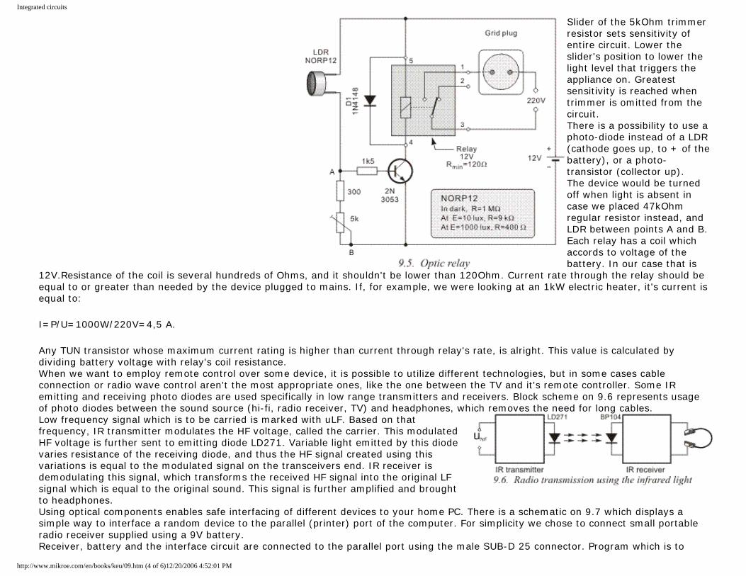
Integrated circuits
Slider of the 5kOhm trimmer resistor sets sensitivity of entire circuit. Lower the slider's position to lower the light level that triggers the appliance on. Greatest sensitivity is reached when trimmer is omitted from the circuit. There is a possibility to use a photo-diode instead of a LDR (cathode goes up, to + of the battery), or a photo-transistor (collector up). The device would be turned off when light is absent in case we placed 47kOhm regular resistor instead, and LDR between points A and B. Each relay has a coil which accords to voltage of the battery. In our case that is
12V.Resistance of the coil is several hundreds of Ohms, and it shouldn't be lower than 120Ohm. Current rate through the relay should be equal to or greater than needed by the device plugged to mains. If, for example, we were looking at an 1kW electric heater, it's current is equal to:
I=P/U=1000W/220V=4,5 A.
Any TUN transistor whose maximum current rating is higher than current through relay's rate, is alright. This value is calculated by dividing battery voltage with relay's coil resistance. When we want to employ remote control over some device, it is possible to utilize different technologies, but in some cases cable connection or radio wave control aren't the most appropriate ones, like the one between the TV and it's remote controller. Some IR emitting and receiving photo diodes are used specifically in low range transmitters and receivers. Block scheme on 9.6 represents usage of photo diodes between the sound source (hi-fi, radio receiver, TV) and headphones, which removes the need for long cables. Low frequency signal which is to be carried is marked with uLF. Based on that frequency, IR transmitter modulates the HF voltage, called the carrier. This modulated HF voltage is further sent to emitting diode LD271. Variable light emitted by this diode varies resistance of the receiving diode, and thus the HF signal created using this variations is equal to the modulated signal on the transceivers end. IR receiver is demodulating this signal, which transforms the received HF signal into the original LF signal which is equal to the original sound. This signal is further amplified and brought to headphones. Using optical components enables safe interfacing of different devices to your home PC. There is a schematic on 9.7 which displays a simple way to interface a random device to the parallel (printer) port of the computer. For simplicity we chose to connect small portable radio receiver supplied using a 9V battery. Receiver, battery and the interface circuit are connected to the parallel port using the male SUB-D 25 connector. Program which is to
http://www.mikroe.com/en/books/keu/09.htm (4 of 6)12/20/2006 4:52:01 PM
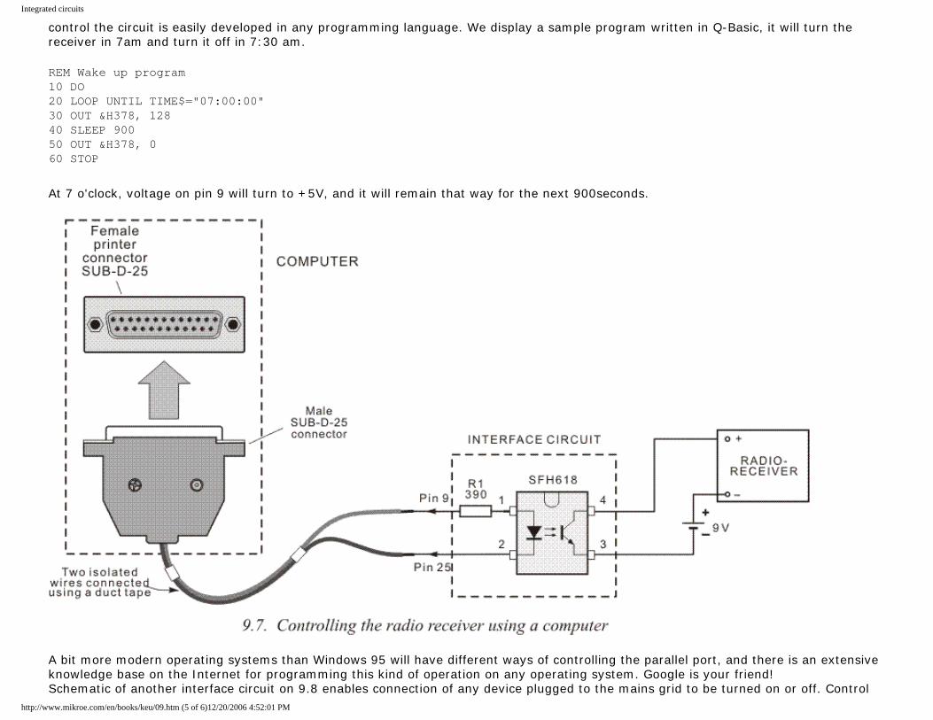
Integrated circuits
control the circuit is easily developed in any programming language. We display a sample program written in Q-Basic, it will turn the receiver in 7am and turn it off in 7:30 am.
REM Wake up program 10 DO 20 LOOP UNTIL TIME$="07:00:00" 30 OUT &H378, 128 40 SLEEP 900 50 OUT &H378, 0 60 STOP
At 7 o'clock, voltage on pin 9 will turn to +5V, and it will remain that way for the next 900seconds.
A bit more modern operating systems than Windows 95 will have different ways of controlling the parallel port, and there is an extensive knowledge base on the Internet for programming this kind of operation on any operating system. Google is your friend! Schematic of another interface circuit on 9.8 enables connection of any device plugged to the mains grid to be turned on or off. Control
http://www.mikroe.com/en/books/keu/09.htm (5 of 6)12/20/2006 4:52:01 PM
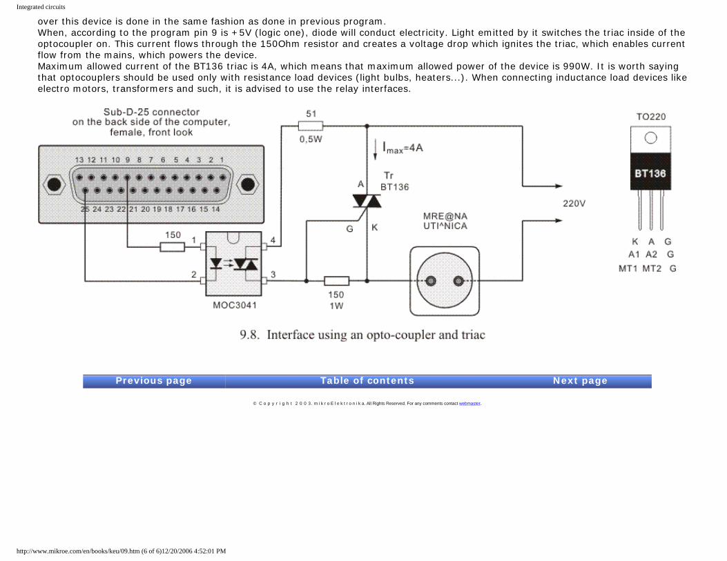
Integrated circuits
over this device is done in the same fashion as done in previous program. When, according to the program pin 9 is +5V (logic one), diode will conduct electricity. Light emitted by it switches the triac inside of the optocoupler on. This current flows through the 150Ohm resistor and creates a voltage drop which ignites the triac, which enables current flow from the mains, which powers the device. Maximum allowed current of the BT136 triac is 4A, which means that maximum allowed power of the device is 990W. It is worth saying that optocouplers should be used only with resistance load devices (light bulbs, heaters...). When connecting inductance load devices like electro motors, transformers and such, it is advised to use the relay interfaces.
Previous page Table of contents Next page
© C o p y r i g h t 2 0 0 3. m i k r o E l e k t r o n i k a. All Rights Reserved. For any comments contact webmaster.
http://www.mikroe.com/en/books/keu/09.htm (6 of 6)12/20/2006 4:52:01 PM
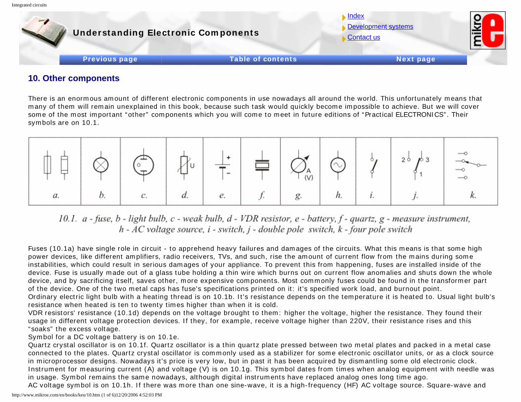
Integrated circuits
Understanding Electronic Components
IndexDevelopment systemsContact us
Previous page Table of contents Next page
10. Other components
There is an enormous amount of different electronic components in use nowadays all around the world. This unfortunately means that many of them will remain unexplained in this book, because such task would quickly become impossible to achieve. But we will cover some of the most important “other” components which you will come to meet in future editions of “Practical ELECTRONICS”. Their symbols are on 10.1.
Fuses (10.1a) have single role in circuit - to apprehend heavy failures and damages of the circuits. What this means is that some high power devices, like different amplifiers, radio receivers, TVs, and such, rise the amount of current flow from the mains during some instabilities, which could result in serious damages of your appliance. To prevent this from happening, fuses are installed inside of the device. Fuse is usually made out of a glass tube holding a thin wire which burns out on current flow anomalies and shuts down the whole device, and by sacrificing itself, saves other, more expensive components. Most commonly fuses could be found in the transformer part of the device. One of the two metal caps has fuse's specifications printed on it: it's specified work load, and burnout point. Ordinary electric light bulb with a heating thread is on 10.1b. It's resistance depends on the temperature it is heated to. Usual light bulb's resistance when heated is ten to twenty times higher than when it is cold. VDR resistors' resistance (10.1d) depends on the voltage brought to them: higher the voltage, higher the resistance. They found their usage in different voltage protection devices. If they, for example, receive voltage higher than 220V, their resistance rises and this “soaks” the excess voltage. Symbol for a DC voltage battery is on 10.1e. Quartz crystal oscillator is on 10.1f. Quartz oscillator is a thin quartz plate pressed between two metal plates and packed in a metal case connected to the plates. Quartz crystal oscillator is commonly used as a stabilizer for some electronic oscillator units, or as a clock source in microprocessor designs. Nowadays it's price is very low, but in past it has been acquired by dismantling some old electronic clock. Instrument for measuring current (A) and voltage (V) is on 10.1g. This symbol dates from times when analog equipment with needle was in usage. Symbol remains the same nowadays, although digital instruments have replaced analog ones long time ago. AC voltage symbol is on 10.1h. If there was more than one sine-wave, it is a high-frequency (HF) AC voltage source. Square-wave and
http://www.mikroe.com/en/books/keu/10.htm (1 of 6)12/20/2006 4:52:03 PM
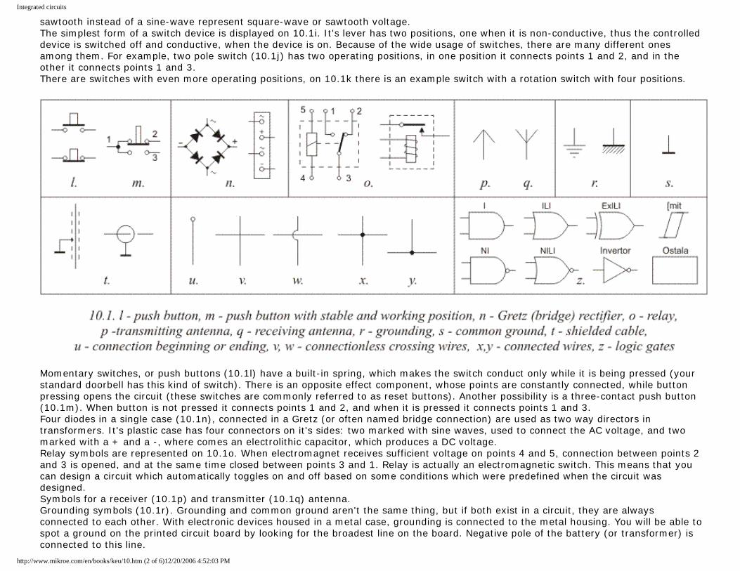
Integrated circuits
sawtooth instead of a sine-wave represent square-wave or sawtooth voltage. The simplest form of a switch device is displayed on 10.1i. It's lever has two positions, one when it is non-conductive, thus the controlled device is switched off and conductive, when the device is on. Because of the wide usage of switches, there are many different ones among them. For example, two pole switch (10.1j) has two operating positions, in one position it connects points 1 and 2, and in the other it connects points 1 and 3. There are switches with even more operating positions, on 10.1k there is an example switch with a rotation switch with four positions.
Momentary switches, or push buttons (10.1l) have a built-in spring, which makes the switch conduct only while it is being pressed (your standard doorbell has this kind of switch). There is an opposite effect component, whose points are constantly connected, while button pressing opens the circuit (these switches are commonly referred to as reset buttons). Another possibility is a three-contact push button (10.1m). When button is not pressed it connects points 1 and 2, and when it is pressed it connects points 1 and 3. Four diodes in a single case (10.1n), connected in a Gretz (or often named bridge connection) are used as two way directors in transformers. It's plastic case has four connectors on it's sides: two marked with sine waves, used to connect the AC voltage, and two marked with a + and a -, where comes an electrolithic capacitor, which produces a DC voltage. Relay symbols are represented on 10.1o. When electromagnet receives sufficient voltage on points 4 and 5, connection between points 2 and 3 is opened, and at the same time closed between points 3 and 1. Relay is actually an electromagnetic switch. This means that you can design a circuit which automatically toggles on and off based on some conditions which were predefined when the circuit was designed. Symbols for a receiver (10.1p) and transmitter (10.1q) antenna. Grounding symbols (10.1r). Grounding and common ground aren't the same thing, but if both exist in a circuit, they are always connected to each other. With electronic devices housed in a metal case, grounding is connected to the metal housing. You will be able to spot a ground on the printed circuit board by looking for the broadest line on the board. Negative pole of the battery (or transformer) is connected to this line.
http://www.mikroe.com/en/books/keu/10.htm (2 of 6)12/20/2006 4:52:03 PM
Integrated circuits
Shielded cables (10.1t) are usually used when a signal is weak or for some reason far from it's amplifier. Typical example is a microphone cable, which sends audio signal to the amplifier. If normal cable was used instead of a shielded one, it would act as a receiving antenna, and therefore receive large amount of unwanted signals, like different voltages from the mains grid, various interferences like cars, elevators, home appliances, mobile phones, etc. End result of this would have been an irritating noise produced by the speakers. Because of this, shielded cables have a conductive outer layer which looks like a net and is always connected to the ground. Because of this, the outer layer now forms a Farad's cage, which blocks outer electromagnetic interferences from reaching core wire, enabling it now to carry only the clear signal from the source to the amplifier. Schematic symbol for a beginning or ending of some conducting line. Symbols for pairs of crossing, but not connected, wires are on 10.1v and 10.1w. Connected crosses are on 10.1x and 10.1y. Schematic symbols representing logic gates and different digital integrated circuits are on 10.1z. It should be kept in mind that basic logic gates (AND, OR, XOR, Inverter, etc.) aren't manufactured as single standalone components. They are always integrated in groups in one IC (7.4a), but for the sake of clarity, they are represented as separate blocks on the schematics. These components demand a DC voltage, which might or might not be represented on the schematic, but is always considered as given. These voltages might be different depending on the internal structure and technology used between different family types. Detailed info on this can be found in component's datasheet provided by the manufacturer. As said, four NAND gates on 7.4a are separate blocks on the schematic, but different numbers on their inputs and outputs state that they come from the same case, and those numbers represent pin numbers of that case. Supply for all four gates is connected between pins 14 (positive) and 7 (negative)
10.1 Relays
Relay is an electro mechanic device which is commonly used to bridge the gap in the circuit, where an electronic circuit is connected to some device connected to the mains grid, whose 220V AC may prove deadly for other components intended for much lower DC voltages. Simply put, relay is an electro-mechanical switch which is opened and closed using a magnet. Schematic of a relay is on 10.2. Copper wire coil on ferrite core is used as a magnet. Above the magnet itself is a plastic lever with iron head and a spring. In the middle of that lever there is a metal fin with small platinum cylinders. Same cylinders are on pins 1 and 2. When current is conducted through pins 4 and 5 to the coil, lever is drawn to the magnet, which disconnects fin from pin 2, thus opening the circuit between 3 and two. Fin is connected to the cylinder on pin 1 and closes the circuit between pins 3 and 1. When there is no voltage on 4 and 5, magnet is off and the lever springs back to it's original position closing the circuit between pins 3 and 2 and opening one between 3 and 1.
http://www.mikroe.com/en/books/keu/10.htm (3 of 6)12/20/2006 4:52:03 PM
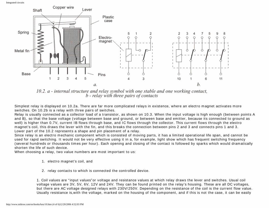
Integrated circuits
Simplest relay is displayed on 10.2a. There are far more complicated relays in existence, where an electro magnet activates more switches. On 10.2b is a relay with three pairs of switches. Relay is usually connected as a collector load of a transistor, as shown on 10.3. When the input voltage is high enough (between points A and B), so that the base voltage (voltage between base and ground, or between base and emitter, because its connected to ground as well) is higher than 0.7V, current IB flows through base, and IC flows through the collector. This current flows through the electro magnet's coil, this draws the lever with the fin, and this breaks the connection between pins 2 and 3 and connects pins 1 and 3. Lower part of the 10.2 represents a shape and pin placement of a relay. Since relay is an electro mechanic component which is consisted of moving parts, it has a limited operational life span, and cannot be used for rapid switching. It would not be very effective using it in a, for example, light show which has frequent switching frequency (several hundreds or thousands times per hour). Each opening and closing of the contact is followed by sparks which would dramatically shorten the life of such device. When choosing a relay, two value numbers are most important to us:
1. electro magnet's coil, and
2. relay contacts to which is connected the controlled device.
1. Coil values are “input values”or voltage and resistance values at which relay draws the lever and switches. Usual coil voltage values are 3V, 5V, 6V, 12V and 24V. They can be found printed on the relay's housing. These are all DC voltages, but there are AC voltage designed relays with 230V/250V. Depending on the resistance of the coil is the current flow value. Usually resistance is,with the voltage, marked on the housing of the component, and if this is not the case, it can be easily
http://www.mikroe.com/en/books/keu/10.htm (4 of 6)12/20/2006 4:52:03 PM
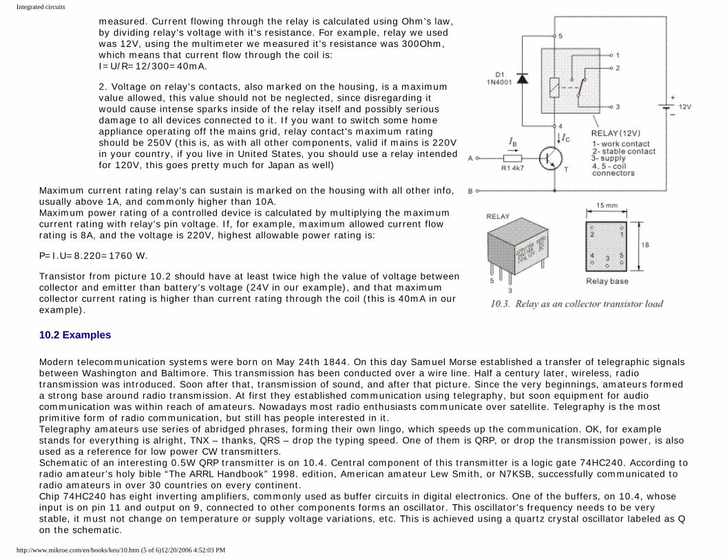
Integrated circuits
measured. Current flowing through the relay is calculated using Ohm's law, by dividing relay's voltage with it's resistance. For example, relay we used was 12V, using the multimeter we measured it's resistance was 300Ohm, which means that current flow through the coil is: I=U/R=12/300=40mA. 2. Voltage on relay's contacts, also marked on the housing, is a maximum value allowed, this value should not be neglected, since disregarding it would cause intense sparks inside of the relay itself and possibly serious damage to all devices connected to it. If you want to switch some home appliance operating off the mains grid, relay contact's maximum rating should be 250V (this is, as with all other components, valid if mains is 220V in your country, if you live in United States, you should use a relay intended for 120V, this goes pretty much for Japan as well)
Maximum current rating relay's can sustain is marked on the housing with all other info, usually above 1A, and commonly higher than 10A. Maximum power rating of a controlled device is calculated by multiplying the maximum current rating with relay's pin voltage. If, for example, maximum allowed current flow rating is 8A, and the voltage is 220V, highest allowable power rating is: P=I.U=8.220=1760 W. Transistor from picture 10.2 should have at least twice high the value of voltage between collector and emitter than battery's voltage (24V in our example), and that maximum collector current rating is higher than current rating through the coil (this is 40mA in our example).
10.2 Examples
Modern telecommunication systems were born on May 24th 1844. On this day Samuel Morse established a transfer of telegraphic signals between Washington and Baltimore. This transmission has been conducted over a wire line. Half a century later, wireless, radio transmission was introduced. Soon after that, transmission of sound, and after that picture. Since the very beginnings, amateurs formed a strong base around radio transmission. At first they established communication using telegraphy, but soon equipment for audio communication was within reach of amateurs. Nowadays most radio enthusiasts communicate over satellite. Telegraphy is the most primitive form of radio communication, but still has people interested in it. Telegraphy amateurs use series of abridged phrases, forming their own lingo, which speeds up the communication. OK, for example stands for everything is alright, TNX – thanks, QRS – drop the typing speed. One of them is QRP, or drop the transmission power, is also used as a reference for low power CW transmitters. Schematic of an interesting 0.5W QRP transmitter is on 10.4. Central component of this transmitter is a logic gate 74HC240. According to radio amateur's holy bible “The ARRL Handbook” 1998. edition, American amateur Lew Smith, or N7KSB, successfully communicated to radio amateurs in over 30 countries on every continent. Chip 74HC240 has eight inverting amplifiers, commonly used as buffer circuits in digital electronics. One of the buffers, on 10.4, whose input is on pin 11 and output on 9, connected to other components forms an oscillator. This oscillator's frequency needs to be very stable, it must not change on temperature or supply voltage variations, etc. This is achieved using a quartz crystal oscillator labeled as Q on the schematic.
http://www.mikroe.com/en/books/keu/10.htm (5 of 6)12/20/2006 4:52:03 PM
Integrated circuits
Signal from the oscillator is amplified using the amplifiers made of four buffers connected in parallel. Inputs of these buffers are on pins 2, 4, 6 and 8. Unused buffers on 3, 5, and 7 are connected to ground and outputs remain unconnected (acronym NC you can find on some schematic means Not Connected). Amplified HF signal from the amplifier is on pins 12, 14, 16 and 18 and is connected to coils L1 and L2 and capacitors C7 and C8, to the connector U. This filter represses higher harmonies of the HF signal created by the oscillator. Signal from the oscillator produces square voltage, rich in harmonics and these could interfere with other radio devices, so that part of the circuit is highly recommended. Coaxial cable with 50W impendance is plugged into the connector U. This cable leads HF signal to the emitting antenna. * Transmitter is supplied from 8V DC voltage. Higher voltage should not be used, since this could lead to overheating and damaging of the integrated circuit. * Since this circuit generates an excess heat, heatsink should be added to the design. It could be bought as an “off the shelf” product or made out of an around 1mm thick aluminum sheet, which is glued to the circuit using an epoxy resin or a special paste used to glue heatsinks to your CPU of the PC. * Coil data is given in the spreadsheet in the upper right corner of the picture. They are wound using a 1.6mm copper wire with laque insulation. As shown, you wind the coil using a 9.5mm drill bit. Make sure you wind it tight, curl to curl. Then, you remove the coil from the drill bit and stretch it, so that it's total length is as shown on the spreadsheet. * When pin 1 is connected to ground, oscillator operates, this is achieved by pressing the momentary switch. Resistor R1 and capacitor C3 form a low pass filter. This circuit removes “clicks” which appear when switch's contacts open or close. * Quartz crystal Q has the same resonant frequency as transmitter (30MHz, 20MHz or 15MHz). To establish transmission, transmitter must “fall into” the antenna range (28MHz, 21MHz or 14MHz) and this is achieved by tuning the trimmer capacitor Ct. On 10.5 is an example of a classic shielded cable application. Received LF signal is routed to the amplifier circuit using an ordinary microphone cable. Shielding, made of a conducting wire laced into a net is connected to ground, and the wire core is connected to the amplifier. In the same manner, using a double core shielded cable, a potentiometer, used to regulate the volume is connected to the circuit. Pictures 9.7 and 9.8 hold information applicable to this circuit as well.
Previous page Table of contents Next page
© C o p y r i g h t 2 0 0 3. m i k r o E l e k t r o n i k a. All Rights Reserved. For any comments contact webmaster.
http://www.mikroe.com/en/books/keu/10.htm (6 of 6)12/20/2006 4:52:03 PM
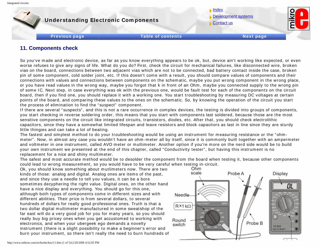
Integrated circuits
Understanding Electronic Components
IndexDevelopment systemsContact us
Previous page Table of contents Next page
11. Components check
So you've made and electronic device, as far as you know everything appears to be ok, but, device ain't working like expected, or even worse refuses to give any signs of life. What do you do? First, check the circuit for mechanical failures, like disconnected wire, broken vias on the board, connections between two adjacent vias which are not to be connected, bad battery contact inside the case, broken pin of some component, cold solder joint, etc. If this doesn't come with a result, you should compare values of components and their connections with values and connections between components on the schematic, maybe you put wrong component in the wrong place, or you have read values in the wrong way, maybe you forgot that k in front of an Ohm, maybe you connected supply to the wrong pin of some IC. Next step, in case everything was ok with the previous one, would be fault test for each of the components on the circuit board, then if you find one, you should replace it with a working one. You start troubleshooting by measuring DC voltages at certain points of the board, and comparing these values to the ones on the schematic. So, by knowing the operation of the circuit you start the process of elimination to find the “suspect” component. If there are several “suspects”, and this is not a rare occurrence in complex devices, the testing is divided into groups of components, you start checking in reverse soldering order, this means that you start with components last soldered, because those are the most sensitive components on the circuit like integrated circuits, transistors, diodes, etc. After that, you should check electrolithic capacitors, since they have a somewhat limited lifespan and leave resistors and block capacitors as last in line since they are sturdy little thingies and can take a lot of beating. The fastest and simplest method to do your troubleshooting would be using an instrument for measuring resistance or the “ohm-meter”. Now, in almost any case you wouldn't have an ohm-meter all by itself, since it is commonly built together with an ampermeter and voltmeter in one instrument, called AVO meter or multimeter. Another option if you're more on the nerd side would be to build your own instrument we presented at the end of this chapter, called “Conductivity tester”, but having this instrument is no replacement for a nice and shiny multimeter. The safest and most accurate method would be to desolder the component from the board when testing it, because other components could lead to wrong measurement, so you would have to be very careful when testing in-circuit. Ok, you should know something about mutlimeters now. There are two kinds of those: analog and digital. Analog ones are items of the past, and since they use a needle to tell you values, it can be a bore sometimes decyphering the right value. Digital ones, on the other hand have a nice display and everything. You should go for this one, although both types of components come in different sizes and with different abilities. Their price is from several dollars, to several hundreds of dollars for really good professional ones. Truth is that a two dollar digital multimeter manufactured in some sweatshop of the far east will do a very good job for you for many years, so you should really buy big pricey ones when you get accustomed to working with electronics, and when your ubergeek ego demands a novelty instrument (there is a slight possibility to make a beginner's error and burn your instrument, so there isn't really the need to burn hundreds of
http://www.mikroe.com/en/books/keu/11.htm (1 of 5)12/20/2006 4:52:05 PM
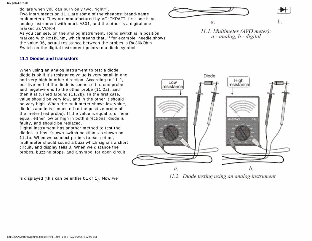
Integrated circuits
dollars when you can burn only two, right?). Two instruments on 11.1 are some of the cheapest brand-name multimeters. They are manufactured by VOLTKRAFT, first one is an analog instrument with mark A801, and the other is a digital one marked as VC404. As you can see, on the analog instrument, round switch is in position marked with Rx1kOhm, which means that, if for example, needle shows the value 36, actual resistance between the probes is R=36kOhm. Switch on the digital instrument points to a diode symbol.
11.1 Diodes and transistors
When using an analog instrument to test a diode, diode is ok if it's resistance value is very small in one, and very high in other direction. According to 11.2, positive end of the diode is connected to one probe and negative end to the other probe (11.2a), and then it is turned around (11.2b). In the first case, value should be very low, and in the other it should be very high. When the multimeter shows low value, diode's anode is connected to the positive probe of the meter (red probe). If the value is equal to or near equal, either low or high in both directions, diode is faulty, and should be replaced. Digital instrument has another method to test the diodes. It has it's own switch position, as shown on 11.1b. When we connect probes to each other, multimeter should sound a buzz which signals a short circuit, and display tells 0. When we distance the probes, buzzing stops, and a symbol for open circuit
is displayed (this can be either 0L or 1). Now we
http://www.mikroe.com/en/books/keu/11.htm (2 of 5)12/20/2006 4:52:05 PM
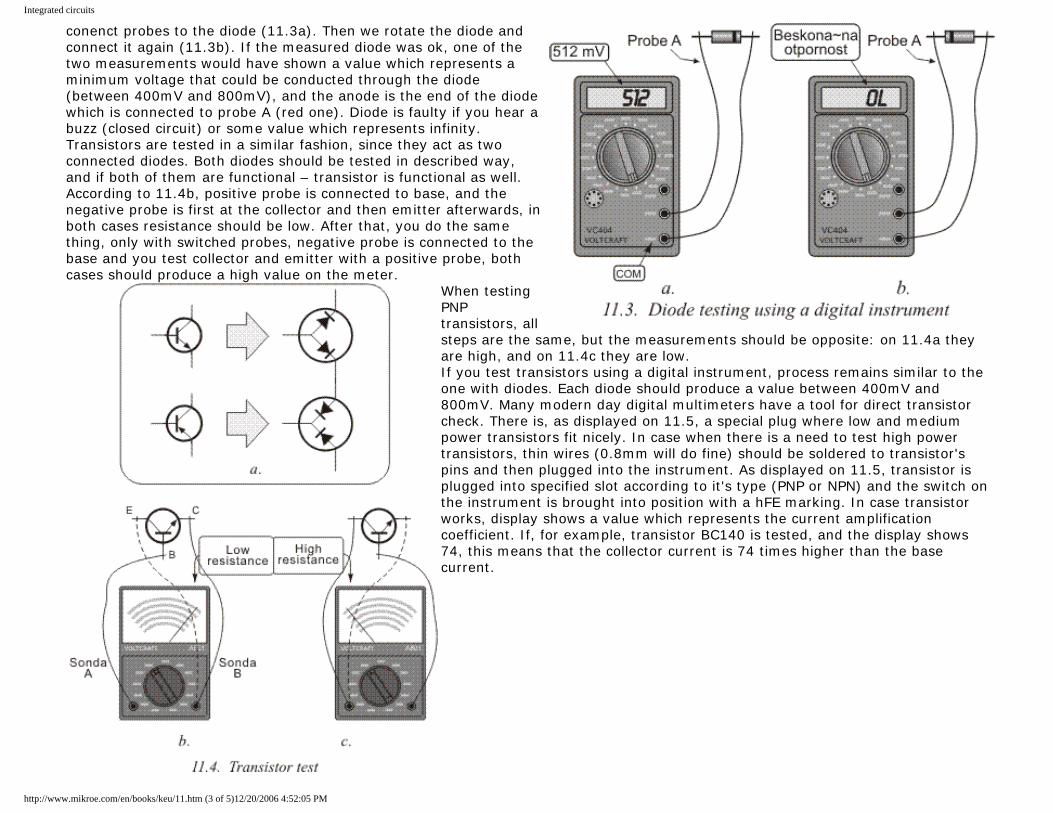
Integrated circuits
conenct probes to the diode (11.3a). Then we rotate the diode and connect it again (11.3b). If the measured diode was ok, one of the two measurements would have shown a value which represents a minimum voltage that could be conducted through the diode (between 400mV and 800mV), and the anode is the end of the diode which is connected to probe A (red one). Diode is faulty if you hear a buzz (closed circuit) or some value which represents infinity. Transistors are tested in a similar fashion, since they act as two connected diodes. Both diodes should be tested in described way, and if both of them are functional – transistor is functional as well. According to 11.4b, positive probe is connected to base, and the negative probe is first at the collector and then emitter afterwards, in both cases resistance should be low. After that, you do the same thing, only with switched probes, negative probe is connected to the base and you test collector and emitter with a positive probe, both cases should produce a high value on the meter.
When testing PNP transistors, all steps are the same, but the measurements should be opposite: on 11.4a they are high, and on 11.4c they are low. If you test transistors using a digital instrument, process remains similar to the one with diodes. Each diode should produce a value between 400mV and 800mV. Many modern day digital multimeters have a tool for direct transistor check. There is, as displayed on 11.5, a special plug where low and medium power transistors fit nicely. In case when there is a need to test high power transistors, thin wires (0.8mm will do fine) should be soldered to transistor's pins and then plugged into the instrument. As displayed on 11.5, transistor is plugged into specified slot according to it's type (PNP or NPN) and the switch on the instrument is brought into position with a hFE marking. In case transistor works, display shows a value which represents the current amplification coefficient. If, for example, transistor BC140 is tested, and the display shows 74, this means that the collector current is 74 times higher than the base current.
http://www.mikroe.com/en/books/keu/11.htm (3 of 5)12/20/2006 4:52:05 PM
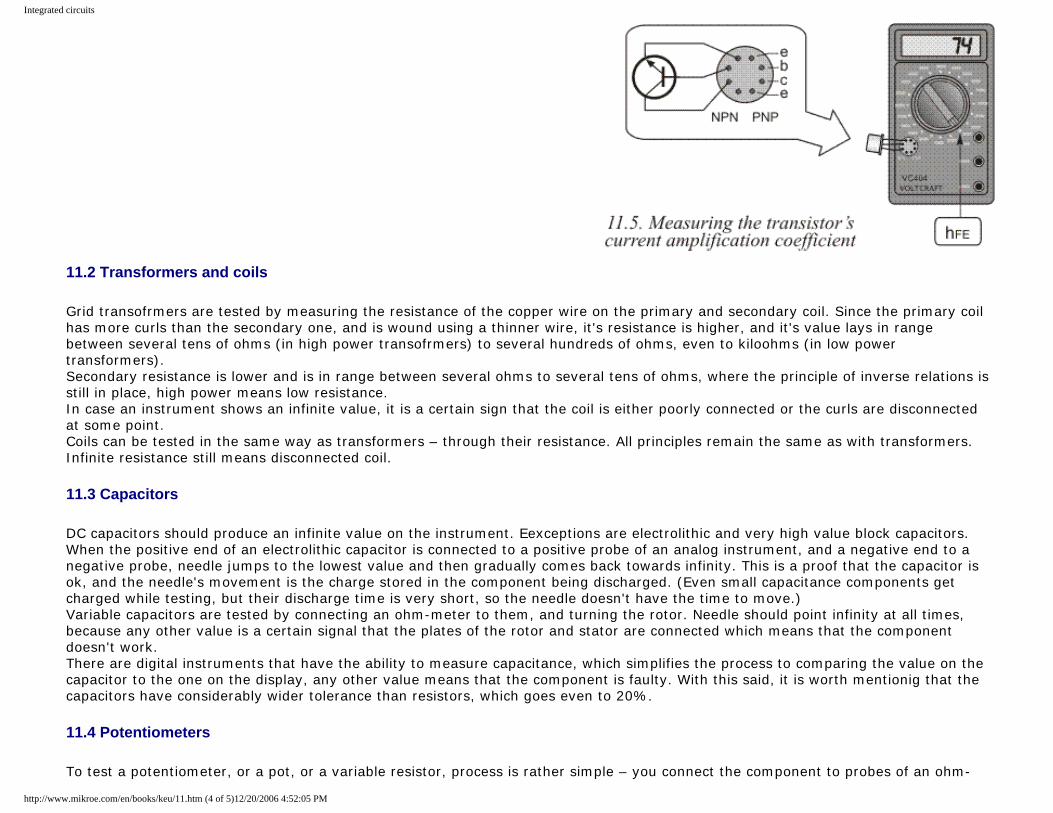
Integrated circuits
11.2 Transformers and coils
Grid transofrmers are tested by measuring the resistance of the copper wire on the primary and secondary coil. Since the primary coil has more curls than the secondary one, and is wound using a thinner wire, it's resistance is higher, and it's value lays in range between several tens of ohms (in high power transofrmers) to several hundreds of ohms, even to kiloohms (in low power transformers). Secondary resistance is lower and is in range between several ohms to several tens of ohms, where the principle of inverse relations is still in place, high power means low resistance. In case an instrument shows an infinite value, it is a certain sign that the coil is either poorly connected or the curls are disconnected at some point. Coils can be tested in the same way as transformers – through their resistance. All principles remain the same as with transformers. Infinite resistance still means disconnected coil.
11.3 Capacitors
DC capacitors should produce an infinite value on the instrument. Eexceptions are electrolithic and very high value block capacitors. When the positive end of an electrolithic capacitor is connected to a positive probe of an analog instrument, and a negative end to a negative probe, needle jumps to the lowest value and then gradually comes back towards infinity. This is a proof that the capacitor is ok, and the needle's movement is the charge stored in the component being discharged. (Even small capacitance components get charged while testing, but their discharge time is very short, so the needle doesn't have the time to move.) Variable capacitors are tested by connecting an ohm-meter to them, and turning the rotor. Needle should point infinity at all times, because any other value is a certain signal that the plates of the rotor and stator are connected which means that the component doesn't work. There are digital instruments that have the ability to measure capacitance, which simplifies the process to comparing the value on the capacitor to the one on the display, any other value means that the component is faulty. With this said, it is worth mentionig that the capacitors have considerably wider tolerance than resistors, which goes even to 20%.
11.4 Potentiometers
To test a potentiometer, or a pot, or a variable resistor, process is rather simple – you connect the component to probes of an ohm-
http://www.mikroe.com/en/books/keu/11.htm (4 of 5)12/20/2006 4:52:05 PM
Integrated circuits
meter and turn the shaft, and values should do what component's name says – vary. Of course, this behavior should be linear – jumps and twitches in values mean that the component is not working as supposed to. If that component was to be used in some audio amplifier, speakers would produce loud noise or no sound at all while pot is being turned. (“Noisy” pot can be repaired using a special spray, or oil or even a graphite pencil, but this is not a good solution since it is weak and short-lived, and should be practiced only if there is no replacement for that potentiometer)
11.1 Speakers, headphones and microphones
When testing speakers, their variable coil has either 4 or 8Ohms in most cases, and the meter should show those values. When using an analog instrument on the speakers, not much of attention is being paid to the value shown on the actual instrument, because by only connecting the probes there should be a short noise heard. If there is no noise, speaker is broken. Same goes for headphones and dynamic microphones. Electret microphones don't produce the noise. And another source of trouble could be the built-in FET amplifier.
Previous page Table of contents Next page
© C o p y r i g h t 2 0 0 3. m i k r o E l e k t r o n i k a. All Rights Reserved. For any comments contact webmaster.
http://www.mikroe.com/en/books/keu/11.htm (5 of 5)12/20/2006 4:52:05 PM
Transistors
Understanding Electronic Components
IndexDevelopment systemsContact us
Previous page Table of contents Next page
4. Transistors
Transistors are active components which are often found in many different electronic circuits. Their play their roles in circuits usually as amplifiers or switch components. As amplifying components they are used in different LF (low frequency) and HF (high frequency) amplifiers, oscillators, modulators, detectors, etc, or in any circuit which needs amplification of voltage, current or power stage. Transistors are used as switches mainly in digital circuits, although they are common in analog ones as well. This means that if the conditions are met, they could switch on or off a part of a circuit, or even in some cases the whole circuit. There is a large number of manufacturers around the world who produce semiconductors (transistors are members of this family of components), so there are literally thousands of different types of transistors. There are low, medium and high power transistors, for working with low and high frequencies, for working with very high current flows, etc. Several different transistors are shown on 4.1. Depending on their principle of work they could be divided into: FET-s and single connection transistors. Most commonly used transistors are bipolar which are divided into NPN and PNP transistors. Their base material is most commonly silicon (then their marking has a letter B) or germanium (in that case their marking has a letter A). There are transistors made of other materials, depending on that their first letter could be C, D or R.
http://www.mikroe.com/en/books/keu/04.htm (1 of 14)12/20/2006 4:52:10 PM
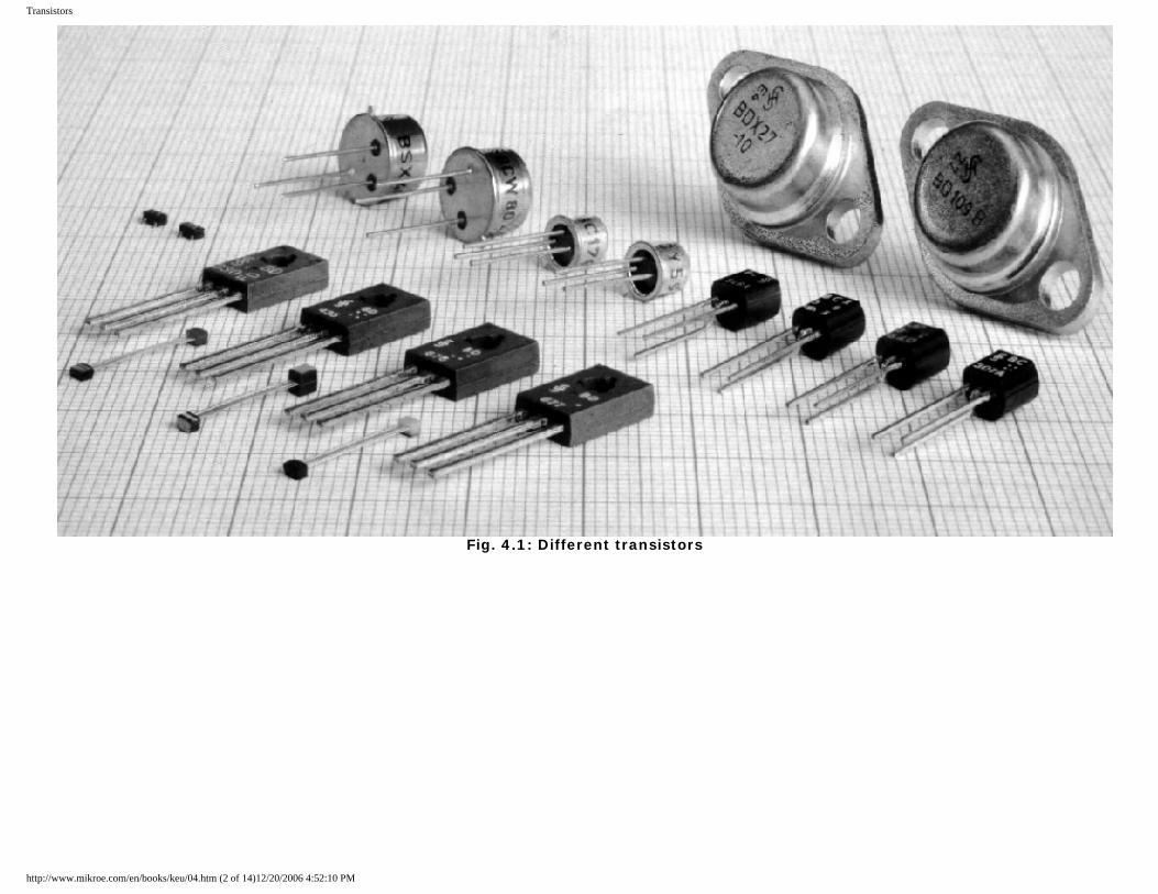
Transistors
Fig. 4.1: Different transistors
http://www.mikroe.com/en/books/keu/04.htm (2 of 14)12/20/2006 4:52:10 PM
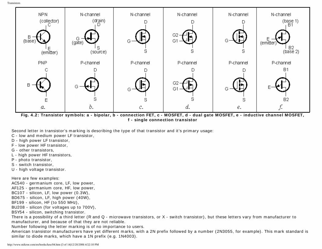
Transistors
Fig. 4.2: Transistor symbols: a - bipolar, b - connection FET, c - MOSFET, d - dual gate MOSFET, e - inductive channel MOSFET,
f - single connection transistor
Second letter in transistor’s marking is describing the type of that transistor and it’s primary usage: C - low and medium power LF transistor, D - high power LF transistor, F - low power HF transistor, G - other transistors, L - high power HF transistors, P - photo transistor, S - switch transistor, U - high voltage transistor. Here are few examples: AC540 - germanium core, LF, low power, AF125 - germanium core, HF, low power, BC107 - silicon, LF, low power (0.3W), BD675 - silicon, LF, high power (40W), BF199 - silicon, HF (to 550 MHz), BU208 - silicon (for voltages up to 700V), BSY54 - silicon, switching transistor. There is a possibility of a third letter (R and Q - microwave transistors, or X - switch transistor), but these letters vary from manufacturer to manufacturer, and because of that they are not reliable. Number following the letter marking is of no importance to users. American transistor manufacturers have yet different marks, with a 2N prefix followed by a number (2N3055, for example). This mark standard is similar to diode marks, which have a 1N prefix (e.g. 1N4003).
http://www.mikroe.com/en/books/keu/04.htm (3 of 14)12/20/2006 4:52:10 PM
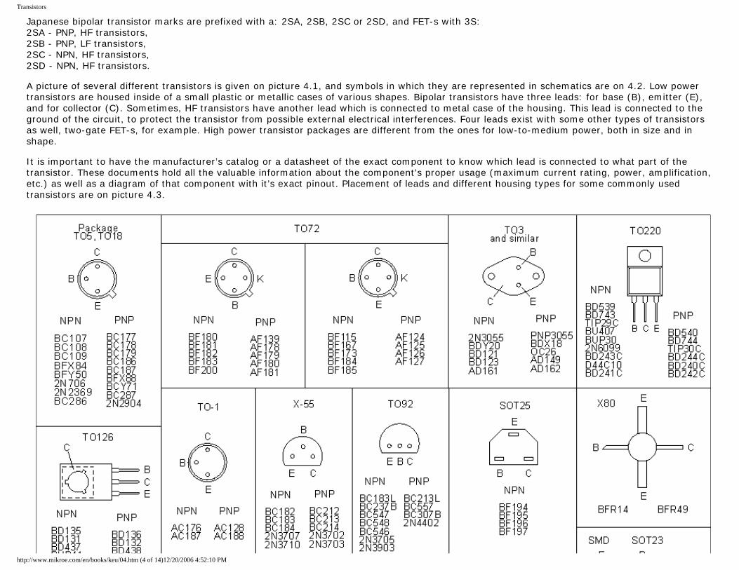
Transistors
Japanese bipolar transistor marks are prefixed with a: 2SA, 2SB, 2SC or 2SD, and FET-s with 3S: 2SA - PNP, HF transistors, 2SB - PNP, LF transistors, 2SC - NPN, HF transistors, 2SD - NPN, HF transistors. A picture of several different transistors is given on picture 4.1, and symbols in which they are represented in schematics are on 4.2. Low power transistors are housed inside of a small plastic or metallic cases of various shapes. Bipolar transistors have three leads: for base (B), emitter (E), and for collector (C). Sometimes, HF transistors have another lead which is connected to metal case of the housing. This lead is connected to the ground of the circuit, to protect the transistor from possible external electrical interferences. Four leads exist with some other types of transistors as well, two-gate FET-s, for example. High power transistor packages are different from the ones for low-to-medium power, both in size and in shape. It is important to have the manufacturer’s catalog or a datasheet of the exact component to know which lead is connected to what part of the transistor. These documents hold all the valuable information about the component's proper usage (maximum current rating, power, amplification, etc.) as well as a diagram of that component with it’s exact pinout. Placement of leads and different housing types for some commonly used transistors are on picture 4.3.
http://www.mikroe.com/en/books/keu/04.htm (4 of 14)12/20/2006 4:52:10 PM
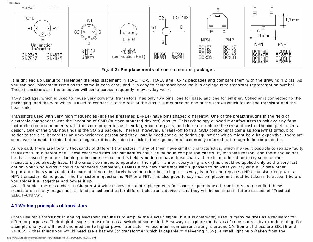
Transistors
Fig. 4.3: Pin placements of some common packages
It might end up useful to remember the lead placement in TO-1, TO-5, TO-18 and TO-72 packages and compare them with the drawing 4.2 (a). As you can see, placement remains the same in each case, and it is easy to remember because it is analogous to transistor representation symbol. These transistors are the ones you will come across frequently in everyday work. TO-3 package, which is used to house very powerful transistors, has only two pins, one for base, and one for emitter. Collector is connected to the packaging, and the wire which is used to connect it to the rest of the circuit is mounted on one of the screws which fasten the transistor and the heat-sink. Transistors used with very high frequencies (like the presented BFR14) have pins shaped differently. One of the breakthroughs in the field of electronic components was the invention of SMD (surface mounted devices) circuits. This technology allowed manufacturers to achieve tiny form factor electronic components with the same properties as their larger counterparts, and therefore reduce the size and cost of the complete user's design. One of the SMD housings is the SOT23 package. There is, however, a trade-off to this, SMD components come as somewhat difficult to solder to the circuitboard for an unexperienced person and they usually need special soldering equipment which might be a bit expensive (there are some workarounds to this, but as a beginner it is advisable to stick to the regular, or as commonly referred to through-hole components). As we said, there are literally thousands of different transistors, many of them have similar characteristics, which makes it possible to replace faulty transistor with different one. These characteristics and similarities could be found in comparison charts. If, for some reason, and there should not be that reason if you are planning to become serious in this field, you do not have those charts, there is no other than to try some of the transistors you already have. If the circuit continues to operate in the right manner, everything is ok (this should be applied only as the very last option, your whole circuit could be rendered completely useless if the new transistor isn't supposed to do what you try with it). Some other important things you should take care of, if you absolutely have no other but doing it this way, is to for one replace a NPN transistor only with a NPN transistor. Same goes if the transistor in question is PNP or a FET. It is also good to say that pin placement must be taken into account before you solder it all together and power it up. As a "first aid" there is a chart in Chapter 4.4 which shows a list of replacements for some frequently used transistors. You can find these transistors in many magazines, all kinds of schematics for different electronic devices, and they will be common in future isssues of "Practical ELECTRONICS".
4.1 Working principles of transistors
Often use for a transistor in analog electronic circuits is to amplify the electric signal, but it is commonly used in many devices as a regulator for different purposes. Their digital usage is most often as a switch of some kind. Best way to explore the basics of transistors is by experimenting. For a simple one, you will need one medium to higher power transistor, whose maximum current rating is around 1A. Some of these are BD135 and 2N3055. Other things you would need are a battery (or transformer which is capable of delivering 4.5V), a small light bulb (taken from the
http://www.mikroe.com/en/books/keu/04.htm (5 of 14)12/20/2006 4:52:10 PM
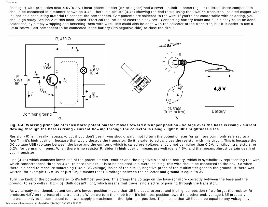
Transistors
flashlight) with properties near 4.5V/0.3A. Linear potentiometer (5K or higher) and a several hundred ohms regular resistor. These components should be connected in a manner shown on 4.4a. There is a picture (4.4b) showing the end result using the 2N3055 transistor. Isolated copper wire is used as a conducting material to connect the components. Components are soldered to the wire. If you're not comfortable with soldering, you should go study Section 2 of this book, called "Practical realization of electronic devices". Connecting battery leads and bulb's body could be done solderless, by simply wrapping and fastening them with wire. This could also be done with the collector of the transistor, but it is easier to use a 3mm screw. Last component to be connected is the battery (it's negative side) to close the circuit.
Fig. 4.4: Working principle of transistors: potentiometer moves toward it's upper position - voltage over the base is rising - current flowing through the base is rising - current flowing through the collector is rising - light bulb's brightness rises Resistor (R) isn't really necessary, but if you don't use it, you should watch not to turn the potentiometer (or as more commonly referred to a "pot") in it's high position, because that would destroy the transistor. So it is safer to actually use the resistor with this circuit. This is because the DC voltage UBE (voltage between the base and the emitter), which is called pre-voltage, should not be higher than 0.6V, for silicon transistors, or 0.2V, for germanium ones. When there is no resistor R, slider in high position means pre-voltage is 4.5V, and that means almost certain death of your transistor. Line (4.4a) which connects lower end of the potentiometer, emitter and the negative side of the battery, which is symbolically representing the wire which connects these three on 4.4b. In case this circuit is to be enclosed in a metal housing, this wire should be connected to the box. So when there is a need to measure something (like a DC voltage) inside of the circuit, negative probe of the multimeter goes to the ground. If there was written, for example UC = 3V or just 3V, it means that DC voltage between the collector and ground is equal to 3V. Turn the knob of the potentiometer to it's leftmost position. This brings the voltage on the base (or more correctly between the base and the ground) to zero volts (UBE = 0). Bulb doesn't light, which means that there is no electricity passing through the transistor. As we already mentioned, potentiometer's lowest position means that UBE is equal to zero, and it's highest position (if we forget the resistor R) produces 4.5V on the base of the transistor. When we turn the knob from it's leftmost position toward the other end, voltage UBE gradually increases, only to become equal to power supply's maximum in the rightmost position. This means that UBE could be equal to any voltage level
http://www.mikroe.com/en/books/keu/04.htm (6 of 14)12/20/2006 4:52:10 PM
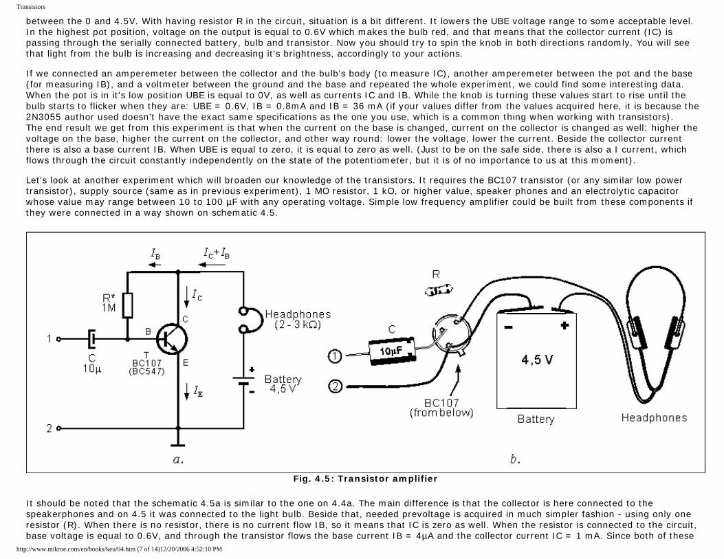
Transistors
between the 0 and 4.5V. With having resistor R in the circuit, situation is a bit different. It lowers the UBE voltage range to some acceptable level. In the highest pot position, voltage on the output is equal to 0.6V which makes the bulb red, and that means that the collector current (IC) is passing through the serially connected battery, bulb and transistor. Now you should try to spin the knob in both directions randomly. You will see that light from the bulb is increasing and decreasing it's brightness, accordingly to your actions. If we connected an amperemeter between the collector and the bulb's body (to measure IC), another amperemeter between the pot and the base (for measuring IB), and a voltmeter between the ground and the base and repeated the whole experiment, we could find some interesting data. When the pot is in it's low position UBE is equal to 0V, as well as currents IC and IB. While the knob is turning these values start to rise until the bulb starts to flicker when they are: UBE = 0.6V, IB = 0.8mA and IB = 36 mA (if your values differ from the values acquired here, it is because the 2N3055 author used doesn't have the exact same specifications as the one you use, which is a common thing when working with transistors). The end result we get from this experiment is that when the current on the base is changed, current on the collector is changed as well: higher the voltage on the base, higher the current on the collector, and other way round: lower the voltage, lower the current. Beside the collector current there is also a base current IB. When UBE is equal to zero, it is equal to zero as well. (Just to be on the safe side, there is also a I current, which flows through the circuit constantly independently on the state of the potentiometer, but it is of no importance to us at this moment). Let's look at another experiment which will broaden our knowledge of the transistors. It requires the BC107 transistor (or any similar low power transistor), supply source (same as in previous experiment), 1 MO resistor, 1 kO, or higher value, speaker phones and an electrolytic capacitor whose value may range between 10 to 100 µF with any operating voltage. Simple low frequency amplifier could be built from these components if they were connected in a way shown on schematic 4.5.
Fig. 4.5: Transistor amplifier
It should be noted that the schematic 4.5a is similar to the one on 4.4a. The main difference is that the collector is here connected to the speakerphones and on 4.5 it was connected to the light bulb. Beside that, needed prevoltage is acquired in much simpler fashion - using only one resistor (R). When there is no resistor, there is no current flow IB, so it means that IC is zero as well. When the resistor is connected to the circuit, base voltage is equal to 0.6V, and through the transistor flows the base current IB = 4µA and the collector current IC = 1 mA. Since both of these
http://www.mikroe.com/en/books/keu/04.htm (7 of 14)12/20/2006 4:52:10 PM
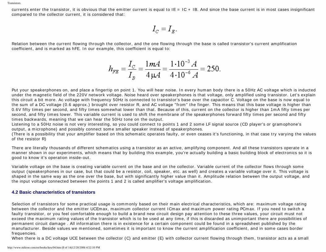
Transistors
currents enter the transistor, it is obvious that the emitter current is equal to IE = IC + IB. And since the base current is in most cases insignificant compared to the collector current, it is considered that:
Relation between the current flowing through the collector, and the one flowing through the base is called transistor's current amplification coefficient, and is marked as hFE. In our example, this coefficient is equal to:
Put your speakerphones on, and place a fingertip on point 1. You will hear noise. In every human body there is a 50Hz AC voltage which is inducted under the magnetic field of the 220V network voltage. Noise heard over speakerphones is that voltage, only amplified using transistor. Let's explain this circuit a bit more. Ac voltage with frequency 50Hz is connected to transistor's base over the capacitor C. Voltage on the base is now equal to the sum of a DC voltage (0.6 approx.) brought over resistor R, and AC voltage "from" the finger. This means that this base voltage is higher than 0.6V fifty times per second, and fifty times somewhat lower than that. Because of this, current on the collector is higher than 1mA fifty times per second, and fifty times lower. This variable current is used to shift the membrane of the speakerphones forward fifty times per second and fifty times backwards, meaning that we can hear the 50Hz tone on the output. Listening to a 50Hz noise is not very interesting, so you could connect to points 1 and 2 some LF signal source (CD player's or gramophone's output, a microphone) and possibly connect some smaller speaker instead of speakerphones. (There is a possibility that your amplifier based on this schematic operates faulty, or even ceases it's functioning, in that case try varying the values of the resistor R) There are literally thousands of different schematics using a transistor as an active, amplifying component. And all these transistors operate in a manner shown in our experiments, which means that by building this example, you're actually building a basic building block of electronics so it is good to know it's operation inside-out. Variable voltage on the base is creating variable current on the base and on the collector. Variable current of the collector flows through some output (speakerphones in our case, but that could be a resistor, coil, speaker, etc. as well) and creates a variable voltage over it. This voltage is shaped in the same way as the one over the base, but with significantly higher value than it. Amplitude relation between the output voltage, and the input voltage connected between the points 1 and 2 is called amplifier's voltage amplification.
4.2 Basic characteristics of transistors
Selection of transistors for some practical usage is commonly based on their main electrical characteristics, which are: maximum voltage rating between the collector and the emitter UCEmax, maximum collector current ICmax and maximum power rating PCmax. If you need to switch a faulty transistor, or you feel comfortable enough to build a brand new circuit design pay attention to these three values, your circuit must not exceed the maximum rating values of the transistor which is to be used at any time, if this is discarded as unimportant there are possibilities of permanent circuit damage . All information there is in existence for a certain component could be found in a spreadsheet published by the manufacturer. Beside values we mentioned, sometimes it is important to know the current amplification coefficient, and in some cases border frequencies. When there is a DC voltage UCE between the collector (C) and emitter (E) with collector current flowing through them, transistor acts as a small
http://www.mikroe.com/en/books/keu/04.htm (8 of 14)12/20/2006 4:52:10 PM
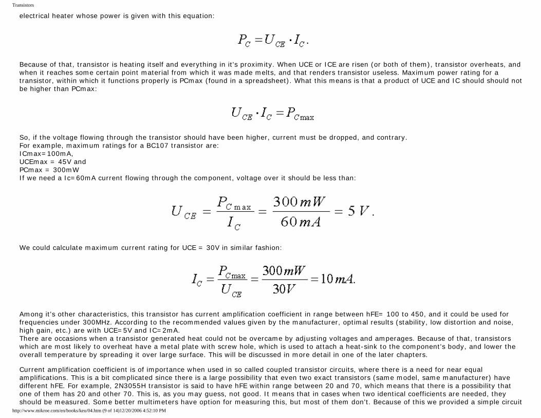
Transistors
electrical heater whose power is given with this equation:
Because of that, transistor is heating itself and everything in it's proximity. When UCE or ICE are risen (or both of them), transistor overheats, and when it reaches some certain point material from which it was made melts, and that renders transistor useless. Maximum power rating for a transistor, within which it functions properly is PCmax (found in a spreadsheet). What this means is that a product of UCE and IC should should not be higher than PCmax:
So, if the voltage flowing through the transistor should have been higher, current must be dropped, and contrary. For example, maximum ratings for a BC107 transistor are: ICmax=100mA, UCEmax = 45V and PCmax = 300mW If we need a Ic=60mA current flowing through the component, voltage over it should be less than:
We could calculate maximum current rating for UCE = 30V in similar fashion:
Among it's other characteristics, this transistor has current amplification coefficient in range between hFE= 100 to 450, and it could be used for frequencies under 300MHz. According to the recommended values given by the manufacturer, optimal results (stability, low distortion and noise, high gain, etc.) are with UCE=5V and IC=2mA. There are occasions when a transistor generated heat could not be overcame by adjusting voltages and amperages. Because of that, transistors which are most likely to overheat have a metal plate with screw hole, which is used to attach a heat-sink to the component's body, and lower the overall temperature by spreading it over large surface. This will be discussed in more detail in one of the later chapters. Current amplification coefficient is of importance when used in so called coupled transistor circuits, where there is a need for near equal amplifications. This is a bit complicated since there is a large possibility that even two exact transistors (same model, same manufacturer) have different hFE. For example, 2N3055H transistor is said to have hFE within range between 20 and 70, which means that there is a possibility that one of them has 20 and other 70. This is, as you may guess, not good. It means that in cases when two identical coefficients are needed, they should be measured. Some better multimeters have option for measuring this, but most of them don't. Because of this we provided a simple circuit
http://www.mikroe.com/en/books/keu/04.htm (9 of 14)12/20/2006 4:52:10 PM
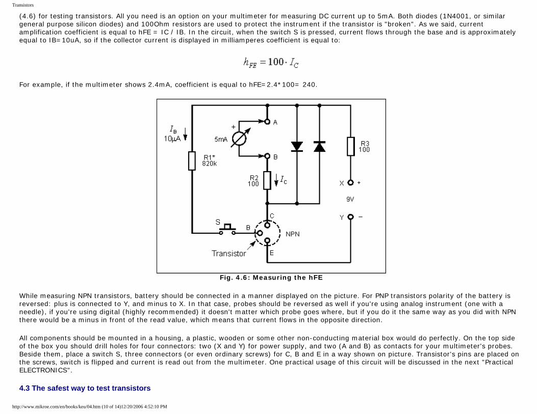
Transistors
(4.6) for testing transistors. All you need is an option on your multimeter for measuring DC current up to 5mA. Both diodes (1N4001, or similar general purpose silicon diodes) and 100Ohm resistors are used to protect the instrument if the transistor is "broken". As we said, current amplification coefficient is equal to hFE = IC / IB. In the circuit, when the switch S is pressed, current flows through the base and is approximately equal to IB=10uA, so if the collector current is displayed in milliamperes coefficient is equal to:
For example, if the multimeter shows 2.4mA, coefficient is equal to hFE=2.4*100= 240.
Fig. 4.6: Measuring the hFE
While measuring NPN transistors, battery should be connected in a manner displayed on the picture. For PNP transistors polarity of the battery is reversed: plus is connected to Y, and minus to X. In that case, probes should be reversed as well if you're using analog instrument (one with a needle), if you're using digital (highly recommended) it doesn't matter which probe goes where, but if you do it the same way as you did with NPN there would be a minus in front of the read value, which means that current flows in the opposite direction.
All components should be mounted in a housing, a plastic, wooden or some other non-conducting material box would do perfectly. On the top side of the box you should drill holes for four connectors: two (X and Y) for power supply, and two (A and B) as contacts for your multimeter's probes. Beside them, place a switch S, three connectors (or even ordinary screws) for C, B and E in a way shown on picture. Transistor's pins are placed on the screws, switch is flipped and current is read out from the multimeter. One practical usage of this circuit will be discussed in the next "Practical ELECTRONICS".
4.3 The safest way to test transistors
http://www.mikroe.com/en/books/keu/04.htm (10 of 14)12/20/2006 4:52:10 PM
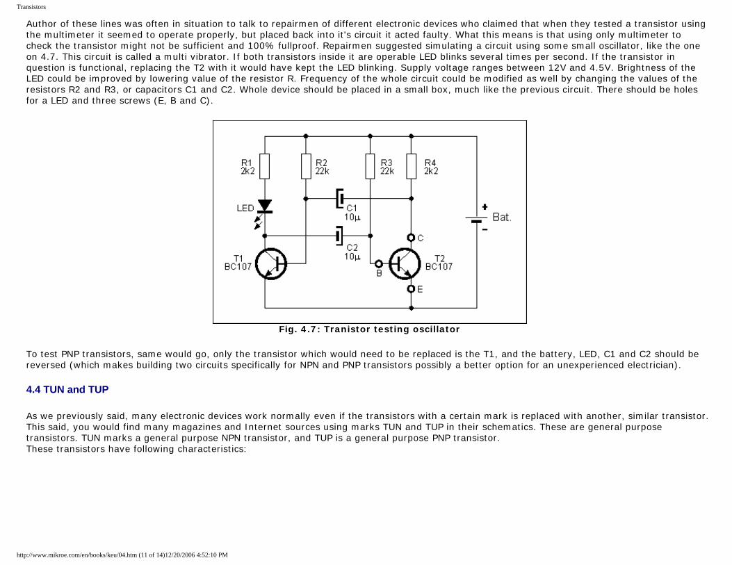
Transistors
Author of these lines was often in situation to talk to repairmen of different electronic devices who claimed that when they tested a transistor using the multimeter it seemed to operate properly, but placed back into it's circuit it acted faulty. What this means is that using only multimeter to check the transistor might not be sufficient and 100% fullproof. Repairmen suggested simulating a circuit using some small oscillator, like the one on 4.7. This circuit is called a multi vibrator. If both transistors inside it are operable LED blinks several times per second. If the transistor in question is functional, replacing the T2 with it would have kept the LED blinking. Supply voltage ranges between 12V and 4.5V. Brightness of the LED could be improved by lowering value of the resistor R. Frequency of the whole circuit could be modified as well by changing the values of the resistors R2 and R3, or capacitors C1 and C2. Whole device should be placed in a small box, much like the previous circuit. There should be holes for a LED and three screws (E, B and C).
Fig. 4.7: Tranistor testing oscillator
To test PNP transistors, same would go, only the transistor which would need to be replaced is the T1, and the battery, LED, C1 and C2 should be reversed (which makes building two circuits specifically for NPN and PNP transistors possibly a better option for an unexperienced electrician).
4.4 TUN and TUP
As we previously said, many electronic devices work normally even if the transistors with a certain mark is replaced with another, similar transistor. This said, you would find many magazines and Internet sources using marks TUN and TUP in their schematics. These are general purpose transistors. TUN marks a general purpose NPN transistor, and TUP is a general purpose PNP transistor. These transistors have following characteristics:
http://www.mikroe.com/en/books/keu/04.htm (11 of 14)12/20/2006 4:52:10 PM
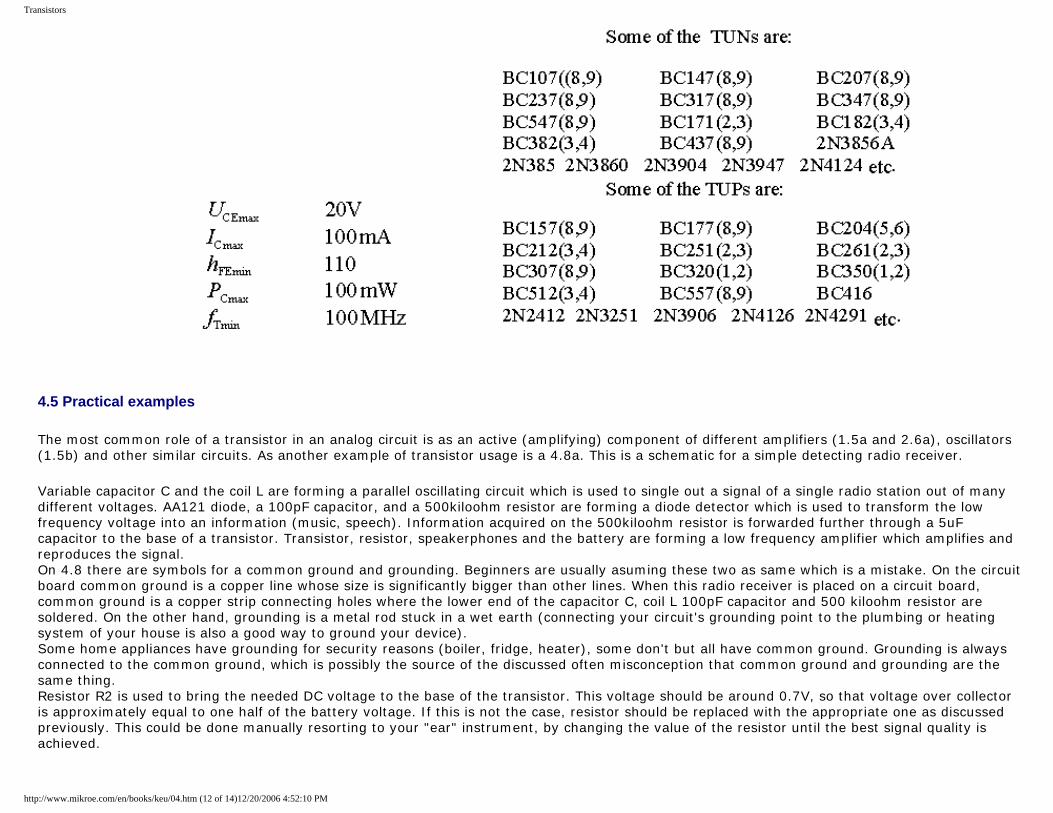
Transistors
4.5 Practical examples
The most common role of a transistor in an analog circuit is as an active (amplifying) component of different amplifiers (1.5a and 2.6a), oscillators (1.5b) and other similar circuits. As another example of transistor usage is a 4.8a. This is a schematic for a simple detecting radio receiver.
Variable capacitor C and the coil L are forming a parallel oscillating circuit which is used to single out a signal of a single radio station out of many different voltages. AA121 diode, a 100pF capacitor, and a 500kiloohm resistor are forming a diode detector which is used to transform the low frequency voltage into an information (music, speech). Information acquired on the 500kiloohm resistor is forwarded further through a 5uF capacitor to the base of a transistor. Transistor, resistor, speakerphones and the battery are forming a low frequency amplifier which amplifies and reproduces the signal. On 4.8 there are symbols for a common ground and grounding. Beginners are usually asuming these two as same which is a mistake. On the circuit board common ground is a copper line whose size is significantly bigger than other lines. When this radio receiver is placed on a circuit board, common ground is a copper strip connecting holes where the lower end of the capacitor C, coil L 100pF capacitor and 500 kiloohm resistor are soldered. On the other hand, grounding is a metal rod stuck in a wet earth (connecting your circuit's grounding point to the plumbing or heating system of your house is also a good way to ground your device). Some home appliances have grounding for security reasons (boiler, fridge, heater), some don't but all have common ground. Grounding is always connected to the common ground, which is possibly the source of the discussed often misconception that common ground and grounding are the same thing. Resistor R2 is used to bring the needed DC voltage to the base of the transistor. This voltage should be around 0.7V, so that voltage over collector is approximately equal to one half of the battery voltage. If this is not the case, resistor should be replaced with the appropriate one as discussed previously. This could be done manually resorting to your "ear" instrument, by changing the value of the resistor until the best signal quality is achieved.
http://www.mikroe.com/en/books/keu/04.htm (12 of 14)12/20/2006 4:52:10 PM
Transistors
Fig. 4.8: Detector receiver with a simple amplifier
Previous page Table of contents Next page
http://www.mikroe.com/en/books/keu/04.htm (13 of 14)12/20/2006 4:52:10 PM

Transistors
© C o p y r i g h t 2 0 0 3. m i k r o E l e k t r o n i k a. All Rights Reserved. For any comments contact webmaster.
http://www.mikroe.com/en/books/keu/04.htm (14 of 14)12/20/2006 4:52:10 PM
Diodes
Understanding Electronic Components
IndexDevelopment systemsContact us
Previous page Table of contents Next page
5. Diodes
As with transistors, diodes are fabricated out of semiconducting materials. So, the first letter in their mark could be an A (germanium diode) or B (silicon diode). They can be encased inside of a glass, metal or plastic housing. They have two leads: a cathode (K) and an anode (A). The most important property of all diodes is that their resistance is very small in one direction, 6O for example, and very large in the opposite, i.e. 600 kO. What this means is that when a diode is in an electrical circuit, voltage on the anode is higher than the voltage on the cathode, and it acts like a low value resistor (6O). If it is connected in the opposite direction it acts like a large value resistor (600 kO). In the first case, it is referred to that diode as conducting polarized, and as nonconducting polarized in the second case. Picture 5.1 depict several different diodes, and picture 5.2 shows their symbols.
http://www.mikroe.com/en/books/keu/05.htm (1 of 7)12/20/2006 4:52:15 PM
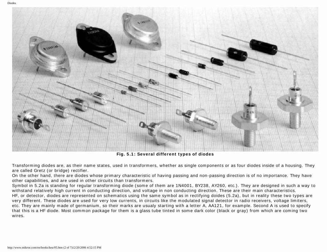
Diodes
Fig. 5.1: Several different types of diodes
Transforming diodes are, as their name states, used in transformers, whether as single components or as four diodes inside of a housing. They are called Gretz (or bridge) rectifier. On the other hand, there are diodes whose primary characteristic of having passing and non-passing direction is of no importance. They have other capabilities, and are used in other circuits than transformers. Symbol in 5.2a is standing for regular transforming diode (some of them are 1N4001, BY238, AY260, etc.). They are designed in such a way to withstand relatively high current in conducting direction, and voltage in non conducting direction. These are their main characteristics. HF, or detector, diodes are represented on schematics using the same symbol as in rectifying doides (5.2a), but in reality these two types are very different. These diodes are used for very low currents, in circuits like the modulated signal detector in radio receivers, voltage limiters, etc. They are mainly made of germanium, so their marks are usualy starting with a letter A, AA121, for example. Second A is used to specify that this is a HF diode. Most common package for them is a glass tube tinted in some dark color (black or gray) from which are coming two wires.
http://www.mikroe.com/en/books/keu/05.htm (2 of 7)12/20/2006 4:52:15 PM
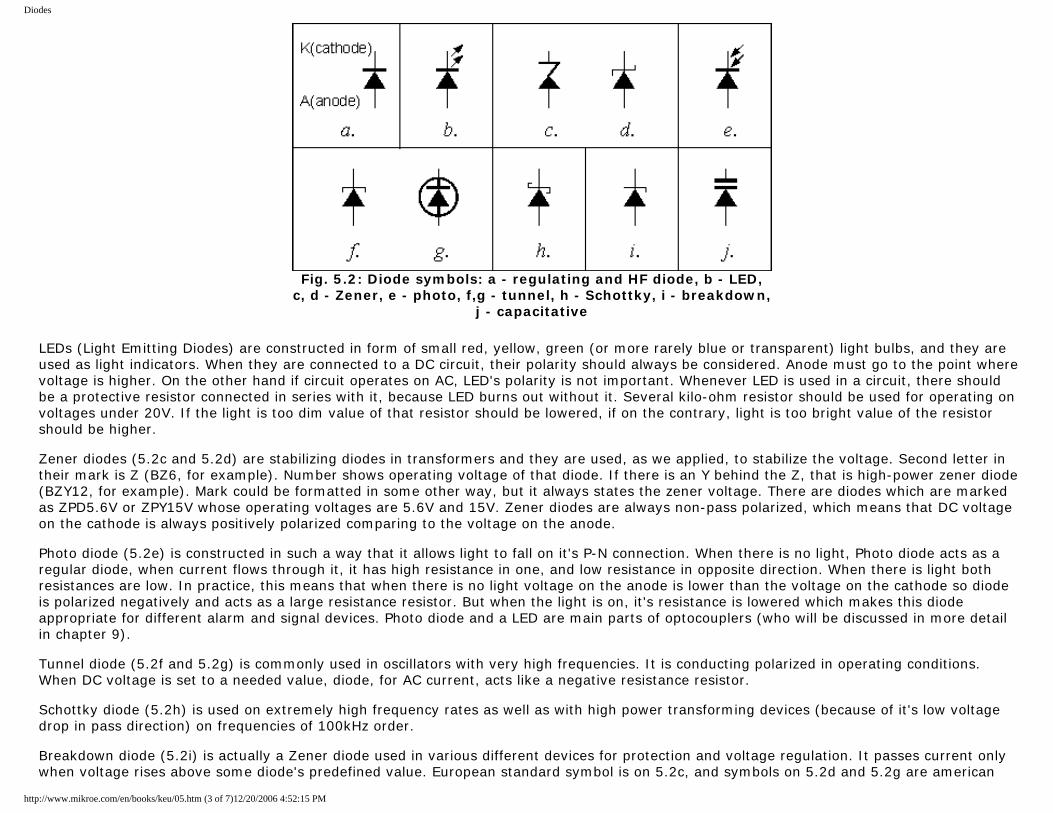
Diodes
Fig. 5.2: Diode symbols: a - regulating and HF diode, b - LED,
c, d - Zener, e - photo, f,g - tunnel, h - Schottky, i - breakdown, j - capacitative
LEDs (Light Emitting Diodes) are constructed in form of small red, yellow, green (or more rarely blue or transparent) light bulbs, and they are used as light indicators. When they are connected to a DC circuit, their polarity should always be considered. Anode must go to the point where voltage is higher. On the other hand if circuit operates on AC, LED's polarity is not important. Whenever LED is used in a circuit, there should be a protective resistor connected in series with it, because LED burns out without it. Several kilo-ohm resistor should be used for operating on voltages under 20V. If the light is too dim value of that resistor should be lowered, if on the contrary, light is too bright value of the resistor should be higher. Zener diodes (5.2c and 5.2d) are stabilizing diodes in transformers and they are used, as we applied, to stabilize the voltage. Second letter in their mark is Z (BZ6, for example). Number shows operating voltage of that diode. If there is an Y behind the Z, that is high-power zener diode (BZY12, for example). Mark could be formatted in some other way, but it always states the zener voltage. There are diodes which are marked as ZPD5.6V or ZPY15V whose operating voltages are 5.6V and 15V. Zener diodes are always non-pass polarized, which means that DC voltage on the cathode is always positively polarized comparing to the voltage on the anode. Photo diode (5.2e) is constructed in such a way that it allows light to fall on it's P-N connection. When there is no light, Photo diode acts as a regular diode, when current flows through it, it has high resistance in one, and low resistance in opposite direction. When there is light both resistances are low. In practice, this means that when there is no light voltage on the anode is lower than the voltage on the cathode so diode is polarized negatively and acts as a large resistance resistor. But when the light is on, it's resistance is lowered which makes this diode appropriate for different alarm and signal devices. Photo diode and a LED are main parts of optocouplers (who will be discussed in more detail in chapter 9). Tunnel diode (5.2f and 5.2g) is commonly used in oscillators with very high frequencies. It is conducting polarized in operating conditions. When DC voltage is set to a needed value, diode, for AC current, acts like a negative resistance resistor. Schottky diode (5.2h) is used on extremely high frequency rates as well as with high power transforming devices (because of it's low voltage drop in pass direction) on frequencies of 100kHz order. Breakdown diode (5.2i) is actually a Zener diode used in various different devices for protection and voltage regulation. It passes current only when voltage rises above some diode's predefined value. European standard symbol is on 5.2c, and symbols on 5.2d and 5.2g are american
http://www.mikroe.com/en/books/keu/05.htm (3 of 7)12/20/2006 4:52:15 PM
Diodes
standard symbolic representations of this diode. Varicap diode (5.2j) is used instead of a variable capacitor in high frequency devices. It's polarized using a DC voltage not to conduct current (cathode has higher voltage than anode). When this voltage's value is changed, capacitance between cathode and anode is changed. This diode is commonly used in radio receivers, transceivers, oscillators, eg. every place that has a demand for variable capacitor with relatively narrow range between it's minimum and maximum value. Low power diode's cathode is marked with a ring painted on the housing of the component, but it is worth noting that some manufacturers label anode this way, so it is best to test it with a multimeter (you'll commonly buy more than one diode, and they come in strips, so it is only needed to test one, others will be the same as that one). Powerful diodes are marked with a symbol engraved on the housing. If diode's internals reside in a metal package, cathode is (not always) connected to it, and anode is a lead that goes through a plastic cap in the housing.
5.1 Diode marks
European diodes are marked using two or three letters and a number. Possible variation of this is a letter behind the number. First letter is used to note the material used in manufacturing of the component (A - germanium, B - silicon), or, in case of letter Z, a Zener diode. The second and third letter specify the sort and usage of that diode. Some of the possibilities are: A - a very low power diode, like the AA111, AA113, AA121, etc. - they are used in the detector unit of a radio receiver; BA124, BA125 : varicap diodes used instead of variable resistors in different receiving devices, oscillators, etc., BAY80, BAY93, etc. - switching diodes used in devices which operate using logic circuits. BA157, BA158, etc. - these are switching diodes with short relapse time. B - two capacitive (varicap) diodes in the same housing, like BB104, BB105, etc. Y - regulation diodes, like BY240, BY243, BY244, etc. - these regulation diodes come in a plastic packaging , and operate on maximum current of 0.8A. If there is another Y behind this one, diodes specifics remain the same, except that they are intended for higher currents. For example, BYY44 is a diode whose absolute maximum current rating is 1A. When Y is the second letter in a Zener diode mark (ZY10, ZY30, etc.) that means that it is intended for higher power usage. G, G, PD - different tolerance marks for Zener diodes. Some of these are ZF12 (5% tolerance), ZG18 (10% tolerance), ZPD9.1 (5% tolerance). Third letter is used to specify the branch of certain two-letters model type with some specific property (designed for higher currents, for example). American markings are beginning with 1N followed by a number, 1N4001, for example (regulating diode), 1N4449 (switching diode), etc. Japanese style is similar to american, the main difference is in that instead of N there is S, 1S241 being one of them. Russian diode marks are consisted of two numbers (GD - germanium, KD - silicon) and a number. As with transistors, number does not have some deeper meaning, it is there only to help users find that specific model in a catalog and see it's specifications. Only difference to that, as already mentioned, are Zener diodes, whose number shows operating voltage of the certain Zener diode.
5.2 Diode characteristics
The most important characteristics when using power diodes used in transformers and similar devices are maximum current rating in conductive direction (IFmax), and maximum voltage they could withstand in non-conductive direction(URmax). One should bear in mind that characteristics read on schematics are effective values. Maximum values, which are important for selection of certain diode are calculated when their effective value is multiplied by 1.41. For example, if the schematic of certain transformer states that secondary voltage of some transformer connected to the wall plug is 12V, maximum voltage of this voltage is 17V, so the diode should have URmax>17V.
http://www.mikroe.com/en/books/keu/05.htm (4 of 7)12/20/2006 4:52:15 PM
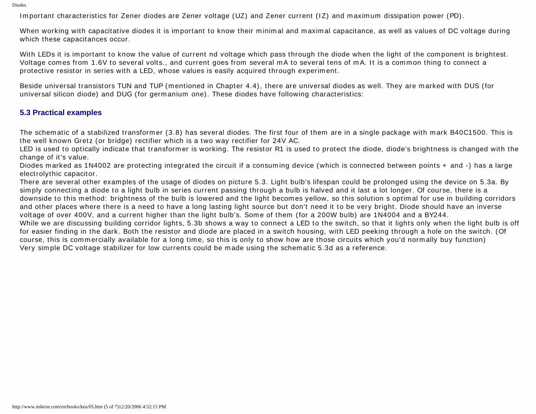
Diodes
Important characteristics for Zener diodes are Zener voltage (UZ) and Zener current (IZ) and maximum dissipation power (PD). When working with capacitative diodes it is important to know their minimal and maximal capacitance, as well as values of DC voltage during which these capacitances occur. With LEDs it is important to know the value of current nd voltage which pass through the diode when the light of the component is brightest. Voltage comes from 1.6V to several volts., and current goes from several mA to several tens of mA. It is a common thing to connect a protective resistor in series with a LED, whose values is easily acquired through experiment. Beside universal transistors TUN and TUP (mentioned in Chapter 4.4), there are universal diodes as well. They are marked with DUS (for universal silicon diode) and DUG (for germanium one). These diodes have following characteristics:
5.3 Practical examples
The schematic of a stabilized transformer (3.8) has several diodes. The first four of them are in a single package with mark B40C1500. This is the well known Gretz (or bridge) rectifier which is a two way rectifier for 24V AC. LED is used to optically indicate that transformer is working. The resistor R1 is used to protect the diode, diode's brightness is changed with the change of it's value. Diodes marked as 1N4002 are protecting integrated the circuit if a consuming device (which is connected between points + and -) has a large electrolythic capacitor. There are several other examples of the usage of diodes on picture 5.3. Light bulb's lifespan could be prolonged using the device on 5.3a. By simply connecting a diode to a light bulb in series current passing through a bulb is halved and it last a lot longer. Of course, there is a downside to this method: brightness of the bulb is lowered and the light becomes yellow, so this solution s optimal for use in building corridors and other places where there is a need to have a long lasting light source but don't need it to be very bright. Diode should have an inverse voltage of over 400V, and a current higher than the light bulb's. Some of them (for a 200W bulb) are 1N4004 and a BY244. While we are discussing building corridor lights, 5.3b shows a way to connect a LED to the switch, so that it lights only when the light bulb is off for easier finding in the dark. Both the resistor and diode are placed in a switch housing, with LED peeking through a hole on the switch. (Of course, this is commercially available for a long time, so this is only to show how are those circuits which you'd normally buy function) Very simple DC voltage stabilizer for low currents could be made using the schematic 5.3d as a reference.
http://www.mikroe.com/en/books/keu/05.htm (5 of 7)12/20/2006 4:52:15 PM
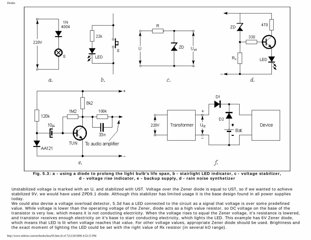
Diodes
Fig. 5.3: a - using a diode to prolong the light bulb's life span, b - stairlight LED indicator, c - voltage stabilizer,
d - voltage rise indicator, e - backup supply, d - rain noise synthetizer
Unstabilized voltage is marked with an U, and stabilized with UST. Voltage over the Zener diode is equal to UST, so if we wanted to achieve stabilized 9V, we would have used ZPD9.1 diode. Although this stabilizer has limited usage it is the base design found in all power supplies today. We could also devise a voltage overload detector, 5.3d has a LED connected to the circuit as a signal that voltage is over some predefined value. While voltage is lower than the operating voltage of the Zener, diode acts as a high value resistor, so DC voltage on the base of the transistor is very low, which means it is not conducting electricity. When the voltage rises to equal the Zener voltage, it's resistance is lowered, and transistor receives enough electricity on it's base to start conducting electricity, which lights the LED. This example has 6V Zener diode, which means that LED is lit when voltage reaches that value. For other voltage values, appropriate Zener diode should be used. Brightness and the exact moment of lighting the LED could be set with the right value of Rx resistor (in several kO range).
http://www.mikroe.com/en/books/keu/05.htm (6 of 7)12/20/2006 4:52:15 PM

Diodes
To modify this circuit in the way that it signals voltage drop below some predefined level, all one should do is swap places of the Zener diode and Rx resistor. For example, by using 12V Zener diode in this manner, we could make an car battery level indicator. So, when voltage drops below 12V, battery taken out from the car and recharged. A bit odd usage for a diode is shown on 5.3e. It is the noise synthesizer, which produces rain like sound. DC current flowing through the conducting polarized diode AA121 isn't absolutely constant, but changes over some middle value (which would be shown using ampermeter connected in series with the diode). This variable component which creates the noise is amplified using transistor (any NPN transistor) and passed over a filter (resistor-capacitor circuit vuth values 33nF and 100kOhms) is brought to an audio amplifier and reproduced on a speaker. One day, author of this book ran really late to work, which by the way cause enormous amount of joy among his students for loosing first three classes. This all happened because of the power failure in the electrical grid, which led to his electrical alarm clock reset (this is the other-side-of-the-fence equivalent to the "dog ate my homework"). In these situations, when some critical device looses it's main power supply, back-up power from the battery should come into picture and remain normal functionality of said device. Schematic 5.3f shows how two diodes, which are able to operate on voltages needed by the device, and a battery are added to the stabilized transformer (this can be any off the shelf transformer you already have for your home appliances). For this to function properly, UIZ voltage should be a bit higher than the voltage over the battery. That makes D2 diode nonconducting, so battery doesn't supply. When network voltage drops, UIZ is zero so D2 conducts electricity, and battery supplies needed electricity. D1 is there to prevent battery to power the transformer, which is needed to prolong the battery life, and protect transformer from damage. For devices up to 1A diode 1N4001 is sufficient, and 1N5400 if amperage is up to 3A.
Previous page Table of contents Next page
© C o p y r i g h t 2 0 0 3. m i k r o E l e k t r o n i k a. All Rights Reserved. For any comments contact webmaster.
http://www.mikroe.com/en/books/keu/05.htm (7 of 7)12/20/2006 4:52:15 PM
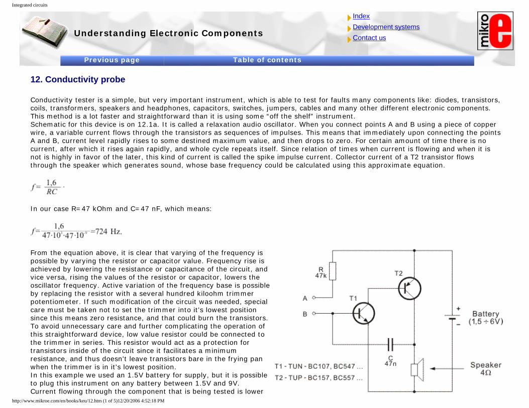
Integrated circuits
Understanding Electronic Components
IndexDevelopment systemsContact us
Previous page Table of contents
12. Conductivity probe
Conductivity tester is a simple, but very important instrument, which is able to test for faults many components like: diodes, transistors, coils, transformers, speakers and headphones, capacitors, switches, jumpers, cables and many other different electronic components. This method is a lot faster and straightforward than it is using some “off the shelf” instrument. Schematic for this device is on 12.1a. It is called a relaxation audio oscillator. When you connect points A and B using a piece of copper wire, a variable current flows through the transistors as sequences of impulses. This means that immediately upon connecting the points A and B, current level rapidly rises to some destined maximum value, and then drops to zero. For certain amount of time there is no current, after which it rises again rapidly, and whole cycle repeats itself. Since relation of times when current is flowing and when it is not is highly in favor of the later, this kind of current is called the spike impulse current. Collector current of a T2 transistor flows through the speaker which generates sound, whose base frequency could be calculated using this approximate equation.
In our case R=47 kOhm and C=47 nF, which means:
From the equation above, it is clear that varying of the frequency is possible by varying the resistor or capacitor value. Frequency rise is achieved by lowering the resistance or capacitance of the circuit, and vice versa, rising the values of the resistor or capacitor, lowers the oscillator frequency. Active variation of the frequency base is possible by replacing the resistor with a several hundred kiloohm trimmer potentiometer. If such modification of the circuit was needed, special care must be taken not to set the trimmer into it's lowest position since this means zero resistance, and that could burn the transistors. To avoid unnecessary care and further complicating the operation of this straightforward device, low value resistor could be connected to the trimmer in series. This resistor would act as a protection for transistors inside of the circuit since it facilitates a minimum resistance, and thus doesn't leave transistors bare in the frying pan when the trimmer is in it's lowest position. In this example we used an 1.5V battery for supply, but it is possible to plug this instrument on any battery between 1.5V and 9V. Current flowing through the component that is being tested is lower
http://www.mikroe.com/en/books/keu/12.htm (1 of 5)12/20/2006 4:52:18 PM
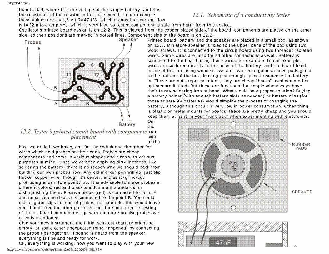
Integrated circuits
than I=U/R, where U is the voltage of the supply battery, and R is the resistance of the resistor in the base circuit. In our example, these values are U=1,5 V i R=47 kW, which means that current flow is I=32 micro amperes, which is very low, so tested component is safe from harm from this device. Oscillator's printed board design is on 12.2. This is viewed from the copper plated side of the board, components are placed on the other side, so their positions are marked in dotted lines. Component side of the board is on 12.2.
Printed board, battery and the speaker are placed in a small box, as shown on 12.3. Miniature speaker is fixed to the upper pane of the box using two wood screws. It is connected to the circuit board using two threaded isolated wires. Same wires are used for all other connections as well. Battery is connected to the board using these wires, for example. In our example, wires are soldered directly to the poles of the battery, and the board fixed inside of the box using wood screws and two rectangular wooden pads glued to the bottom of the box, leaving just enough space to squeeze the battery in. These are not proper solutions, they are cheap “hacks” used when other options are limited. But these are functional for people who always have their trusty soldering iron at hand. What would be a proper solution? Buying a battery holder (with enough battery slots as needed) or battery clips (for those square 9V batteries) would simplify the process of changing the battery, although this circuit is very low in power consumption. Other thing is plastic or metal mounts for boards, these are pretty cheap and you should keep them at hand in your “junk box” when experimenting with electronics.On the front side of the
box, we drilled two holes, one for the switch and the other for wires which hold probes on their ends. Probes are cheap components and come in various shapes and sizes with various purposes in mind. Since we've been applying dirty methods, like soldering the battery, there is no reason why we should back from building our own probes now. Any old marker-pen will do, just slip thicker copper wire through it's center, and sand/grind/cut protruding ends into a pointy tip. It is advisable to make probes in different colors, red and black are dominant standards for distinguishing them. Positive probe (red) is connected to point A, and negative one (black) is connected to the point B. You could use alligator clips instead of probes, for example, this would leave your hands free for other purposes, but for some precise testing of the on-board components, go with the more precise probes we already mentioned. Give your new instrument the initial self-test (battery might be empty, or some other unexpected thing happened) by connecting the probe tips together. If sound is heard from the speaker, everything is fine and ready for work. Ok, everything is working, now you want to play with your new
http://www.mikroe.com/en/books/keu/12.htm (2 of 5)12/20/2006 4:52:18 PM
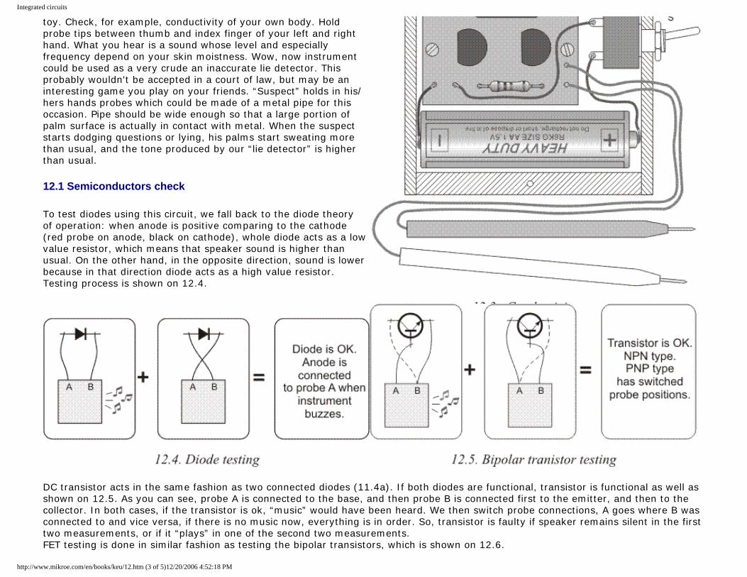
Integrated circuits
toy. Check, for example, conductivity of your own body. Hold probe tips between thumb and index finger of your left and right hand. What you hear is a sound whose level and especially frequency depend on your skin moistness. Wow, now instrument could be used as a very crude an inaccurate lie detector. This probably wouldn't be accepted in a court of law, but may be an interesting game you play on your friends. “Suspect” holds in his/hers hands probes which could be made of a metal pipe for this occasion. Pipe should be wide enough so that a large portion of palm surface is actually in contact with metal. When the suspect starts dodging questions or lying, his palms start sweating more than usual, and the tone produced by our “lie detector” is higher than usual.
12.1 Semiconductors check
To test diodes using this circuit, we fall back to the diode theory of operation: when anode is positive comparing to the cathode (red probe on anode, black on cathode), whole diode acts as a low value resistor, which means that speaker sound is higher than usual. On the other hand, in the opposite direction, sound is lower because in that direction diode acts as a high value resistor. Testing process is shown on 12.4.
DC transistor acts in the same fashion as two connected diodes (11.4a). If both diodes are functional, transistor is functional as well as shown on 12.5. As you can see, probe A is connected to the base, and then probe B is connected first to the emitter, and then to the collector. In both cases, if the transistor is ok, “music” would have been heard. We then switch probe connections, A goes where B was connected to and vice versa, if there is no music now, everything is in order. So, transistor is faulty if speaker remains silent in the first two measurements, or if it “plays” in one of the second two measurements. FET testing is done in similar fashion as testing the bipolar transistors, which is shown on 12.6.
http://www.mikroe.com/en/books/keu/12.htm (3 of 5)12/20/2006 4:52:18 PM
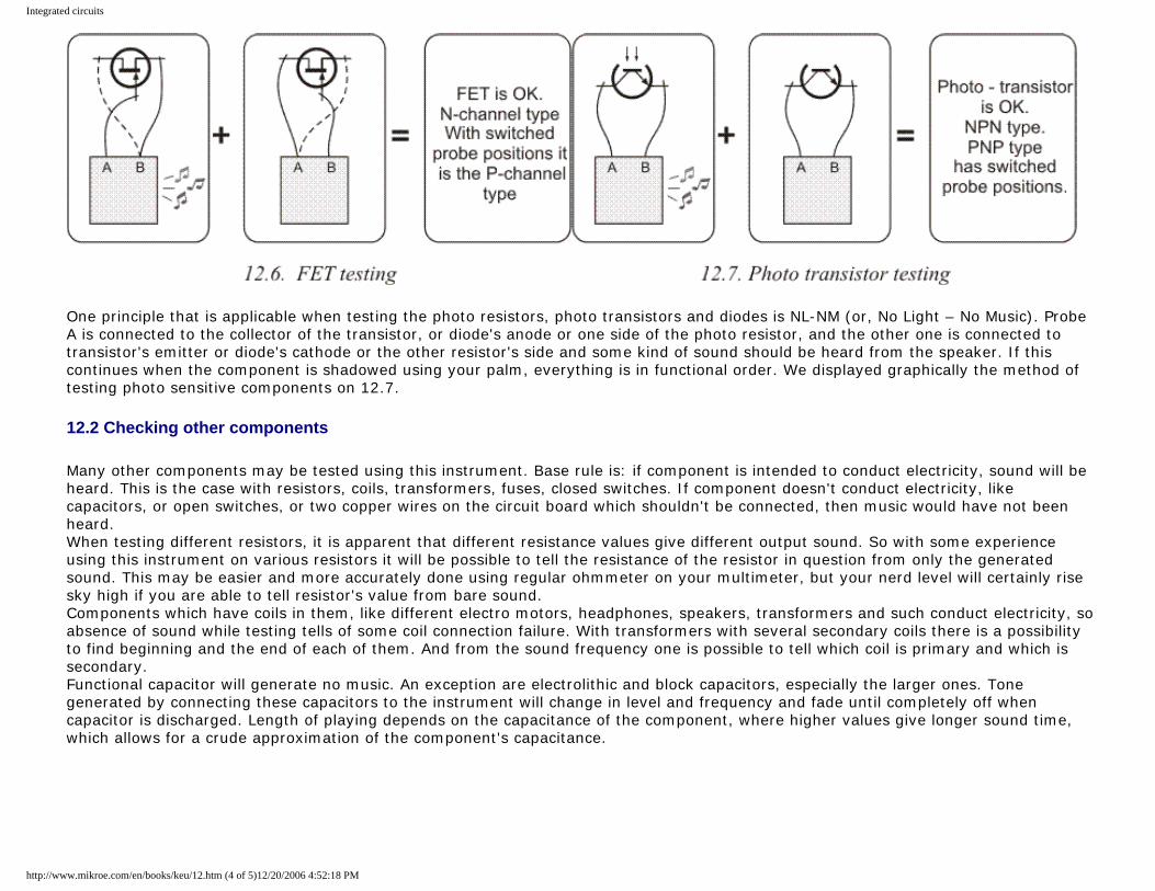
Integrated circuits
One principle that is applicable when testing the photo resistors, photo transistors and diodes is NL-NM (or, No Light – No Music). Probe A is connected to the collector of the transistor, or diode's anode or one side of the photo resistor, and the other one is connected to transistor's emitter or diode's cathode or the other resistor's side and some kind of sound should be heard from the speaker. If this continues when the component is shadowed using your palm, everything is in functional order. We displayed graphically the method of testing photo sensitive components on 12.7.
12.2 Checking other components
Many other components may be tested using this instrument. Base rule is: if component is intended to conduct electricity, sound will be heard. This is the case with resistors, coils, transformers, fuses, closed switches. If component doesn't conduct electricity, like capacitors, or open switches, or two copper wires on the circuit board which shouldn't be connected, then music would have not been heard. When testing different resistors, it is apparent that different resistance values give different output sound. So with some experience using this instrument on various resistors it will be possible to tell the resistance of the resistor in question from only the generated sound. This may be easier and more accurately done using regular ohmmeter on your multimeter, but your nerd level will certainly rise sky high if you are able to tell resistor's value from bare sound. Components which have coils in them, like different electro motors, headphones, speakers, transformers and such conduct electricity, so absence of sound while testing tells of some coil connection failure. With transformers with several secondary coils there is a possibility to find beginning and the end of each of them. And from the sound frequency one is possible to tell which coil is primary and which is secondary. Functional capacitor will generate no music. An exception are electrolithic and block capacitors, especially the larger ones. Tone generated by connecting these capacitors to the instrument will change in level and frequency and fade until completely off when capacitor is discharged. Length of playing depends on the capacitance of the component, where higher values give longer sound time, which allows for a crude approximation of the component's capacitance.
http://www.mikroe.com/en/books/keu/12.htm (4 of 5)12/20/2006 4:52:18 PM

Integrated circuits
Previous page Table of contents
© C o p y r i g h t 2 0 0 3. m i k r o E l e k t r o n i k a. All Rights Reserved. For any comments contact webmaster.
http://www.mikroe.com/en/books/keu/12.htm (5 of 5)12/20/2006 4:52:18 PM