undersea optical communications - university of...
TRANSCRIPT
1
Undersea Optical Communications
Dr. Greg Mooradian QinetiQ North America
Technology Solutions Group 7545 Metropolitan Drive
San Diego, CA 92108 619-725-3700 (voice)
30 August 2012
Presented at Quantum Communication Workshop:
Secure Information Transmission in the Maritime Environment

2
What Are You Going to Hear?
QinetiQ Proprietary
• The Navy’s view of connecting the C4ISR network
• Possible underwater Optical Laser Communications (OLC) architectures supporting a wide range of critical Naval missions
• An overview of the fundamental physics of the all-underwater and underwater/above-water propagation channel and the impact on communications performance
• The state of the art in OLC performance modeling and environmental characterization
• An example of the relationship of OLC architecture and laser and narrowband optical filter selection

3
Connecting the C4ISR Network: Both Above-Water and Undersea Nodes
MPA
Sonobuoys Gateway
Buoy
Fiber with Repeaters
Fishline Array
SURTASS
USV
Bottomed Surveillance
Sensors
UAV
Floating Surveillance
Sensors
UUV UUV
UGS
• • • • • • •
• • • • • • • • • • •
• • • •
ASDS
T-AGOS Comm Links Yellow = RF Blue = Laser Red = Hard Wired 00110 = Acoustics
GOAL: Communicate with underwater assets at operationally useful depths/ranges at operationally useful data rates
4
HDR airborne comm with UUV or gateway buoy
SLC SpotCast
(downlink only)
SLC BeamCast (two-way)
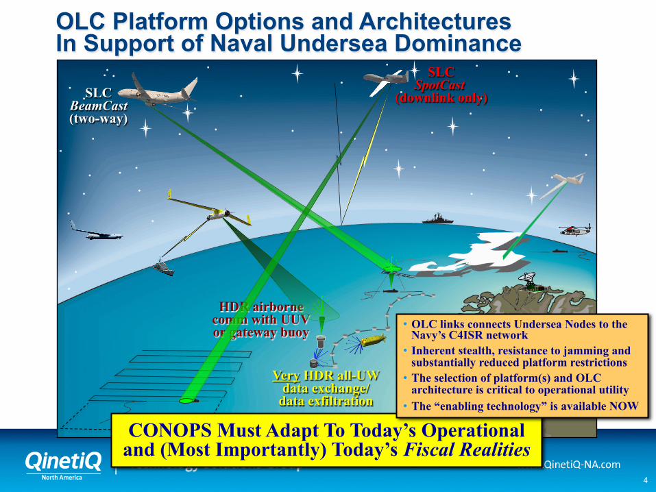
OLC Platform Options and Architectures In Support of Naval Undersea Dominance
Very HDR all-UW data exchange/
data exfiltration
CONOPS Must Adapt To Today’s Operational and (Most Importantly) Today’s Fiscal Realities
• OLC links connects Undersea Nodes to the Navy’s C4ISR network
• Inherent stealth, resistance to jamming and substantially reduced platform restrictions
• The selection of platform(s) and OLC architecture is critical to operational utility
• The “enabling technology” is available NOW

5
• Two OLC comm modes: (1) all-underwater (terminal-to-terminal), and (2) through the air-water interface (UW terminal comm with an above-water terminal)
• All-underwater OLC propagation phenomenology and OLC technology can be significantly different than the through-the air/water-interface link Solar background is generally not a dominating noise source Data rate capability and/or requirements can be substantially larger SWaP terminal requirements are generally much more demanding
• Communications through the air-water interface propagation channel is much more complicated and much more dependent on geometry and the environment Requirement for daytime operation drives many of the technology and
architecture options (e.g., narrowband optical filters and high peak-power lasers) Generally demands much more SWaP and complicated technology (e.g., SLC) To be efficient (especially daytime), requires collection of multiple scattered
signal (placing heavy demands on high peak power lasers and wide FOV filters) Real-time adapting of system parameters is required to optimize performance in
real-world conditions (e.g., anamorphic zoom, adaptive-data-rate-comm)
Architecture, Depth and Data Rate Requirements Define the OLC Geometry
Initial signal acquisition for 2-way comm links (or SpotCast OPAREA scan) is generally the
most complicated operation & defines CONOPS
6
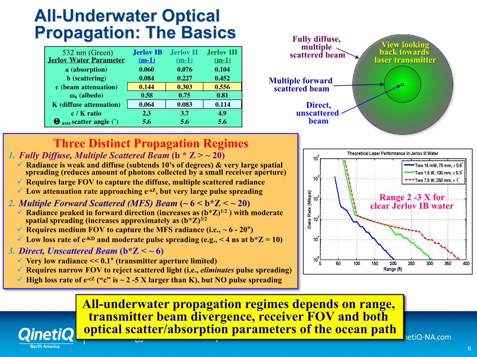
All-Underwater Optical Propagation: The Basics
All-underwater propagation regimes depends on range, transmitter beam divergence, receiver FOV and both
optical scatter/absorption parameters of the ocean path
Fully diffuse, multiple
scattered beam View looking back towards
laser transmitter
Direct, unscattered
beam
Multiple forward scattered beam
Three Distinct Propagation Regimes 1. Fully Diffuse, Multiple Scattered Beam (b * Z > ~ 20)
Radiance is weak and diffuse (subtends 10’s of degrees) & very large spatial spreading (reduces amount of photons collected by a small receiver aperture)
Requires large FOV to capture the diffuse, multiple scattered radiance Low attenuation rate approaching e-aZ, but very large pulse spreading
2. Multiple Forward Scattered (MFS) Beam (~ 6 < b*Z < ~ 20) Radiance peaked in forward direction (increases as (b*Z)1/2 ) with moderate
spatial spreading (increases approximately as (b*Z)3/2 Requires medium FOV to capture the MFS radiance (i.e., ~ 6 - 20°) Low loss rate of e-KD and moderate pulse spreading (e.g., < 4 ns at b*Z = 10)
3. Direct, Unscattered Beam (b*Z < ~ 6) Very low radiance << 0.1° (transmitter aperture limited) Requires narrow FOV to reject scattered light (i,e., eliminates pulse spreading) High loss rate of e-cZ (“c” is ~ 2 -5 X larger than K), but NO pulse spreading
Range 2 -3 X for clear Jerlov IB water
Jerlov Water Parameter Jerlov IB
(m-1)Jerlov II
(m-1)Jerlov III
(m-1)a (absorption) 0.060 0.076 0.104b (scattering) 0.084 0.227 0.452
c (beam attenuation) 0.144 0.303 0.556ω0 (albedo) 0.58 0.75 0.81
K (diffuse attenuation) 0.064 0.083 0.114c / K ratio 2.3 3.7 4.9
RMS scatter angle (˚) 5.6 5.6 5.6
532 nm (Green)

7
• Uplink & downlink are NOT reciprocal: daytime downlink SNR scales as e –KD while uplink SNR scales as: e –2KD / R4
• Basically, everything works great at night or clear
• Uplink comm performance is reduced approx linearly with the range (i.e., increasing scan angle and/or higher altitude)
• Downlink data rate is nominally limited by – Day (cloudy or clear) is SNR limited (i.e., laser energy-per-pulse/
background); Night (cloudy) is cloud pulse-stretching limited – With Tx zoom, data rate is nearly independent of altitude/range – Because of water absorption (vs. scattering), downwelling
radiance moves towards nadir vs. depth & limits to ± 19 °
• Anamorphic Tx zoom and Rx FOV correction vs. nadir angle can increase performance substantially for large angles
• Spatial spreading in clouds reduces received energy/pulse, increases required A/C Rx FOV and complicates scan strategy
• Water turbidity rapidly degrades SNR (i.e., depth & data rate) – “Green” littoral water is more turbid than open-ocean “blue” water
and generally gets clearer (i.e., “bluer”) with depth – Sea state is very much a second order effect and may help at
large nadir angles (clear) – Multiple scattering in sea water (K & D) defines sub Rx FOV
Propagation Channel Characteristics of a Through the Air-Water Interface OLC Channel
Downlink: BOTH signal & background
exponentially attenuated with depth (day)
Uplink: only signal attenuated
with depth (day)
Cloud pulse spreading:
100s of ns to 10s of µs
Water pulse spreading: 10s of ns
Cloud spatial spreading (~ 1.5 x T)
Water: clarity (K) generally gets better
with depth (D)
Cloud: τ optical thickness, T physical thickness at height H
Spot on cloud
Daytime solar background noise
Submarine at Depth (D)
8
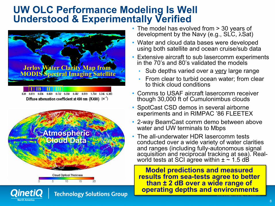
UW OLC Performance Modeling Is Well Understood & Experimentally Verified • The model has evolved from > 30 years of
development by the Navy (e.g., SLC, λSat) • Water and cloud data bases were developed
using both satellite and ocean cruise/sub data • Extensive aircraft to sub lasercomm experiments
in the 70’s and 80’s validated the models • Sub depths varied over a very large range • From clear to turbid ocean water; from clear
to thick cloud conditions • Comms to USAF aircraft lasercomm receiver
though 30,000 ft of Cumulonimbus clouds • SpotCast CSD demos in several airborne
experiments and in RIMPAC ’86 FLEETEX • 2-way BeamCast comm demo between above
water and UW terminals to Mbps • The all-underwater HDR lasercomm tests
conducted over a wide variety of water clarities and ranges (including fully-autonomous signal acquisition and reciprocal tracking at sea). Real-world tests at SCI agree within ± ~ 1.5 dB
Atmospheric Cloud Data
I IB II III
Jerlov Water Clarity Map from MODIS Spectral Imaging Satellite
Model predictions and measured results from sea-tests agree to better
than ± 2 dB over a wide range of operating depths and environments
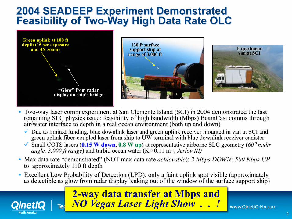
9
• Two-way laser comm experiment at San Clemente Island (SCI) in 2004 demonstrated the last remaining SLC physics issue: feasibility of high bandwidth (Mbps) BeamCast comms through air/water interface to depth in a real ocean environment (both up and down) Due to limited funding, blue downlink laser and green uplink receiver mounted in van at SCI and
green uplink fiber-coupled laser from ship to UW terminal with blue downlink receiver canister Small COTS lasers (0.15 W down, 0.8 W up) at representative airborne SLC geometry (60° nadir
angle, 3,000 ft range) and turbid ocean water (K~ 0.11 m-1, Jerlov III) • Max data rate “demonstrated” (NOT max data rate achievable): 2 Mbps DOWN; 500 Kbps UP
to approximately 110 ft depth • Excellent Low Probability of Detection (LPD): only a faint uplink spot visible (approximately
as detectible as glow from radar display leaking out of the window of the surface support ship)
130 ft surface support ship at range of 3,000 ft
Experiment van at SCI
Green uplink at 100 ft depth (15 sec exposure
and 4X zoom)
“Glow” from radar display on ship’s bridge
2004 SEADEEP Experiment Demonstrated Feasibility of Two-Way High Data Rate OLC
2-way data transfer at Mbps and NO Vegas Laser Light Show . . !
10
The Selection of a Laser and Narrowband Optical Filter
On a Notional OLC Architecture
11
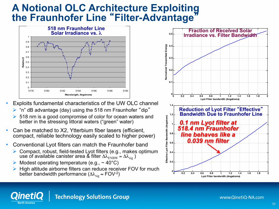
A Notional OLC Architecture Exploiting the Fraunhofer Line “Filter-Advantage”
Fraunghofer lines: Rel. Energy vs Wavelength
0
0.1
0.2
0.3
0.4
0.5
0.6
0.7
0.8
0.9
1
5178 5180 5182 5184 5186 5188 5190
Wavelength, Angstroms
Rela
tive
E
518 nm Fraunhofer Line Solar Irradiance vs. λ
0 0.2 0.4 0.6 0.8 1 1.2 1.4 1.6 1.8 20
0.1
0.2
0.3
0.4
0.5
Lyot Filter bandwidth (Angstroms)
Norm
aliz
ed T
rans
mitt
ed E
nerg
y
Fraction of Received Solar Irradiance vs. Filter Bandwidth
0 0.2 0.4 0.6 0.8 1 1.2 1.4 1.6 1.8 20
0.2
0.4
0.6
0.8
1
1.2
1.4
Lyot Filter bandwidth (Angstroms)
Effe
ctiv
e Ly
ot F
ilter
Ban
dwid
th (A
ngst
rom
)
Reduction of Lyot Filter “Effective” Bandwidth Due to Fraunhofer Line
0.1 nm Lyot filter at 518.4 nm Fraunhofer line behaves like a
0.039 nm filter
• Exploits fundamental characteristics of the UW OLC channel “n” dB advantage (day) using the 518 nm Fraunhofer “dip” 518 nm is a good compromise of color for ocean waters and
better in the stressing littoral waters (“green” water)
• Can be matched to X2, Ytterbium fiber lasers (efficient, compact, reliable technology easily scaled to higher power)
• Conventional Lyot filters can match the Fraunhofer band Compact, robust, field-tested Lyot filters (e.g., makes optimum
use of available canister area & filter ΔλENBW = Δλsig ) Modest operating temperature (e.g., ~ 40°C) High altitude airborne filters can reduce receiver FOV for much
better bandwidth performance (Δλsig ≈ FOV-2)
12
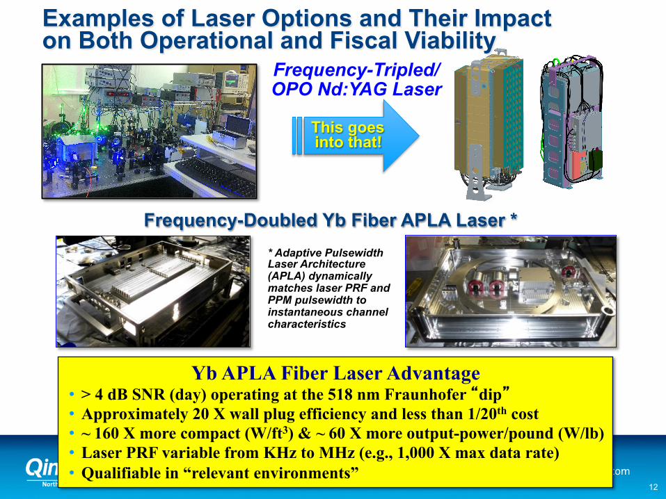
Yb APLA Fiber Laser Advantage • > 4 dB SNR (day) operating at the 518 nm Fraunhofer “dip” • Approximately 20 X wall plug efficiency and less than 1/20th cost • ~ 160 X more compact (W/ft3) & ~ 60 X more output-power/pound (W/lb)
• Laser PRF variable from KHz to MHz (e.g., 1,000 X max data rate) • Qualifiable in “relevant environments”
This goes into that!
Frequency-Tripled/OPO Nd:YAG Laser
Frequency-Doubled Yb Fiber APLA Laser * * Adaptive Pulsewidth Laser Architecture (APLA) dynamically matches laser PRF and PPM pulsewidth to instantaneous channel characteristics
Examples of Laser Options and Their Impact on Both Operational and Fiscal Viability

13
The OLC Bottom Line
Fiber Optic Cable
Optical (Clear Water)
Data Rate 1.0
Mbps 100
Kbps 10
Kbps 1.0
Kbps 100 bps
10 bps
10 Gbps
1.0 Gbps
100 Mbps
10 Mbps
1 m
10 m
100 m
1 Km
10 Km
100 Km
1,000 Km
Und
erw
ater
Ran
ge
Optical (Turbid Water)
Acoustics
RF
UW Comm Performance vs. Technology
• Legacy systems (RF or acoustics) do not meet the requirements to connect the undersea environment either due to physics, lack of stealth, insufficient bandwidth and/or the ability to be jammed or otherwise denied
• Most importantly, only OLC can transfer tactically-significant information through the air-water interface
• While Comms at Speed and Depth (CSD) has been a persistent objective for the Submarine Fleet since the 1970’s, CSD (e.g., SLC) has not become an operational capability for the Fleet (mostly due to both real and perceived cost)
• ISR is critical to the Navy’s mission The collection of offboard ISR is only of use to
the warfighter if it can be transferred with high fidelity and low latency(i.e., high bandwidth)
The “Unmanned-Imperative” (e.g., UAVs, UUVs), which is so critical to affordability, makes information transfer even more difficult
Minimizing platform operational limitations (e.g., speed, depth, tethers and cables) is key to operational utility
• Fundamental “physics” defines underwater comm range/data-rate performance

14
Questions?