umts introduction 1
TRANSCRIPT

© Alcatel University –10445ACAAWBZZA Ed.1 Page 1
UMTS/UTRAN Introduction
Training Manuel3FL10445ACAAWBZZA Ed.1
September 2005

© Alcatel University –10445ACAAWBZZA Ed.1 Page 2
Contents
1 Introduction1.1 Context1.2 Standardization1.3 UMTS Goals1.4 UMTS Technical Overview
2 Services Provided2.1 UMTS Services Principles2.1 UMTS Bearer Services2.3 Tele-Services2.4 UMTS Terminals
3 UTRAN System Description3.1 Logical Architecture3.2 Network Protocols3.3 Radio Channels3.4 Radio Protocols
4 WCDMA for UMTS4.1 Context4.2 Analogy4.3 Spread spectrum modulation4.4 Code Division Multiple Access (CDMA)4.5 Soft handover4.6 Rake receiver4.7 Power control4.8 Capacity, Coverage & Quality
5 UTRAN Scenario5.1 Radio Channels Mapping5.2 Service Request5.3 RAB Establishment5.4 Mobility Management in Connected Mode

© Alcatel University –10445ACAAWBZZA Ed.1 Page 3
Objectives
Instructional objectives Yes (or
Globally yes)
No (or globally
no) Comments
1 Describe mobile system standards evolution
2 Describe UMTS services , new capacity figures and service architecture
3 Draw the UTRAN architecture with the protocol stack (radio & network) of each Network Element and to define the channels used by these protocols
4 Define a Radio Resource in 3G.
5 Build the map of the channels (logical, transport, physical) from a white paper
Contract number :
Course title :
Client (Company, centre) :
Language : dates from : to :
Number of trainees : Location :
Surname, First name :
Did you meet the following objectives ?Tick the corresponding box
Please, return this sheet to the trainer at the end of the training

© Alcatel University –10445ACAAWBZZA Ed.1 Page 4
1. INTRODUCTION
© Alcatel University –10445ACAAWBZZA Ed.1 Page 5
UMTS/UTRAN Introduction 3FL10445ACAAWBZZA Ed.1 Page 5
Introduction Content> Objective: to be able to describe mobile system standards
evolution
> Program:
• Context• Standardization• UMTS Goals• UMTS Technical Overview

© Alcatel University –10445ACAAWBZZA Ed.1 Page 6
1. INTRODUCTION
1.1 Context
© Alcatel University –10445ACAAWBZZA Ed.1 Page 7
UMTS/UTRAN Introduction 3FL10445ACAAWBZZA Ed.1 Page 7
CONTEXTDefinition
Universal
Mobile
Telecommunication
System
“UMTS is one of the major new third generation mobile communications systems being developed within the framework which has been defined by the ITU and known as IMT-2000”
UMTS Forum
Will explain “3rd generation”-->1.1 HistoricalWill explain “IMT-2000 defined by ITU”-->1.2 Standardization
The UMTS Forum is an international and independent body, uniquely committed through the building of cross-industry consensus to the successful introduction and development of UMTS/IMT-2000 ’’third generation’’ mobile communications systemswww.umts-forum.org
© Alcatel University –10445ACAAWBZZA Ed.1 Page 8
UMTS/UTRAN Introduction 3FL10445ACAAWBZZA Ed.1 Page 8
CONTEXTPast mobile systems (1)
First Generation (1G)
In the early 80’s, analog systemse.g Radiocom 2000, C-Netz…
Service:speech
Limitations of 1G:•poor spectrum efficiency•expensive and heavy user equipment•mobility only in a small area •no security of communications

© Alcatel University –10445ACAAWBZZA Ed.1 Page 9
UMTS/UTRAN Introduction 3FL10445ACAAWBZZA Ed.1 Page 9
Second Generation (2G)In the early 90’s, digital systemsEurope : GSMUS : IS-95 (also called cdmaOne), IS-136 (TDMA system) Japan : PDC
Services: Speech and low data rate
Limitations of 2G:• Congestionmore than 300 million wireless subscribers worldwide -->need to increase system capacity
• Limited mobility around the world -->need for a global standardisation
• Limited offer of servicesmore than 200 million internet users--> Need for new multimedia services and applications (video telephony, e-commerce...)
CONTEXTPast mobile systems (2)
• Congestionmore than 300 million wireless subscribers worldwide -->booming market -->congestion of 2G (Japan case )-->need to increase system capacity
• Limited mobility around the worldgreat amount of 2G systems not compatible with each other-->need for a global standardisation
• Limited offer of servicesmore than 200 million internet users ⇒ communications are not limited to speech anymore ⇒ 2G are too limited to offer data services (low bit rate, circuit switching) ⇒ Need for new multimedia services and applications (video telephony, e-commerce...)
© Alcatel University –10445ACAAWBZZA Ed.1 Page 10
UMTS/UTRAN Introduction 3FL10445ACAAWBZZA Ed.1 Page 10
CONTEXTTechnical solutions
Two types of solutions were possible :
• enhancement of 2G system --> 2,5Glow cost but short terme.g.: HSCSD, GPRS, EDGE for GSM evolution
• design of a complete new standard --> 3Ghigh cost, long term, but great amount of new potential servicese.g: UMTS

© Alcatel University –10445ACAAWBZZA Ed.1 Page 11
UMTS/UTRAN Introduction 3FL10445ACAAWBZZA Ed.1 Page 11
CONTEXTGSM evolution (1)HSCSD (High Speed Circuit Switched Data)Principle: to enhance channel coding scheme and to bundle GSM time slots on a circuit-switched basis.
Performance: up to 115,2 kbps
Already implemented but not all operators/manufacturers have made this choice.
GPRS (General Packet Radio Service)
Principle: to enhance channel coding scheme and to bundle GSM time slots on a packet-switched basis (the allocation of time slots is performed dynamically at the initialisation and during the connection)
Performance: up to 171,2 kbps
1999/2000 : deployment phase2002 : service offers for most operators
Note: Alcatel will skip HSCSD!
© Alcatel University –10445ACAAWBZZA Ed.1 Page 12
UMTS/UTRAN Introduction 3FL10445ACAAWBZZA Ed.1 Page 12
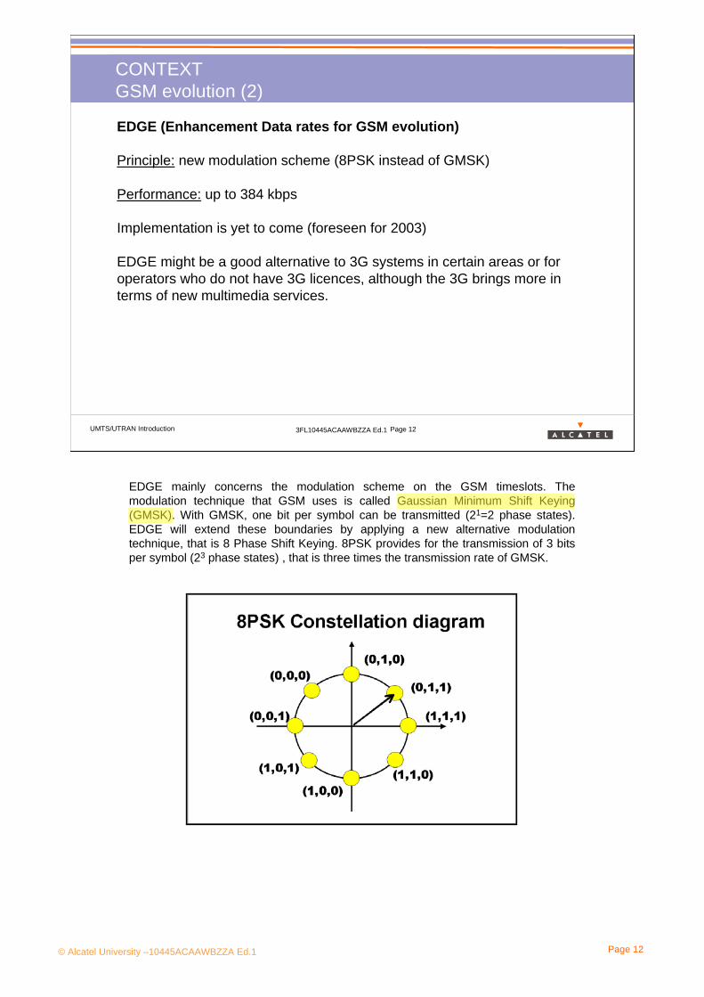
EDGE (Enhancement Data rates for GSM evolution)
Principle: new modulation scheme (8PSK instead of GMSK)
Performance: up to 384 kbps
Implementation is yet to come (foreseen for 2003)
EDGE might be a good alternative to 3G systems in certain areas or for operators who do not have 3G licences, although the 3G brings more in terms of new multimedia services.
CONTEXTGSM evolution (2)
EDGE mainly concerns the modulation scheme on the GSM timeslots. The modulation technique that GSM uses is called Gaussian Minimum Shift Keying (GMSK). With GMSK, one bit per symbol can be transmitted (21=2 phase states). EDGE will extend these boundaries by applying a new alternative modulation technique, that is 8 Phase Shift Keying. 8PSK provides for the transmission of 3 bits per symbol (23 phase states) , that is three times the transmission rate of GMSK.

© Alcatel University –10445ACAAWBZZA Ed.1 Page 13
UMTS/UTRAN Introduction 3FL10445ACAAWBZZA Ed.1 Page 13
CONTEXTLet’s take some examples!
> A 2 1/2 minutes MP3 music file (2.4 MBytes)
GSM 34 mnGPRS 7 mnEDGE 128 s UMTS 10 s
> Audio and Video streaming
Streaming with alltechnologies
except with GSM
> Downloading a map (50 KBytes)
GSM 42 sGPRS 8 sEDGE 3 sUMTS 0.2 s
> Downloading a Word document(500 KBytes)
GSM 7 mnGPRS 82 sEDGE 27 sUMTS 2 s
In these examples, the useful rate is supposed to be :9.6 Kbps for GSM50 Kbps for GPRS150 Kbps for EDGE2 Mbps for UMTS
same examples with different rates for GPRS :Downloading a Map: 13 s with GPRS CS-2 and 3 Time Slots (~30Kbps)Downloading a Word Document: 135 s with GPRS CS-2 and 3 Time Slots

© Alcatel University –10445ACAAWBZZA Ed.1 Page 14
1. INTRODUCTION
1.2 Standardization

© Alcatel University –10445ACAAWBZZA Ed.1 Page 15
UMTS/UTRAN Introduction 3FL10445ACAAWBZZA Ed.1 Page 15
STANDARDIZATION IMT-2000: definition
IMT-2000 is a framework for third generation mobile systems (3G) which is scheduled to start service worldwide around the year 2000 subject to market considerations.
IMT-2000 should use the frequencies around 2 GHz all over the world.
IMT-2000 is defined by a set of interdependent ITU Recommendations*.
IMT-2000 main requirements are :- wide range of high quality services- capability for multimedia applications - worldwide roaming capability - compatibility of services within IMT-2000 and with the fixed networks
*A recommendation is not a specification.
IMT-2000: International Mobile Telecommunications-2000ITU:International Telecommunication Union (www.itu.int)
Problem: 2GHz is already used by 2G systems in US : shall the frequency carriers of 2G be reframed? Isn’t EDGE the most suitable technology for 3G systems?

© Alcatel University –10445ACAAWBZZA Ed.1 Page 16
UMTS/UTRAN Introduction 3FL10445ACAAWBZZA Ed.1 Page 16
STANDARDIZATIONIMT-2000: main participants
Europe: ETSI
Japan: ARIB
USA: TIA, T1
South Korea: TTA
China: CWTS
ITU: International Telecommunication Union
ITU is an international organisation composed of members of governments all over the world.
ETSI, ARIB, TIA… are regional standardization bodies composed of companies such as manufacturers and operators.
IMT-2000 is a result of the collaboration between the ITU and several regional standardization bodies, which are located mainly in Europe, in Japan and in the US
In the first phase of 3rd generation standardization, each region carried out its own standardization process to meet the IMT-2000 requirements but also to take into account its own 2nd generation mobile systems.
As similar technologies were being standardized in several regions around the world, initiatives were made to create a single forum for WCDMA standardization for a common WCDMA specification, e.g 3GPP (Third Generation Project Partnership), 3GPP2
Each Consortium has proposed one or more Radio Interfaces for IMT-2000, which have been approved for ITU. UMTS contains the two interfaces standardized by 3GPP: IMT-DS and IMT-TC.

© Alcatel University –10445ACAAWBZZA Ed.1 Page 17
UMTS/UTRAN Introduction 3FL10445ACAAWBZZA Ed.1 Page 17
STANDARDIZATIONIMT-2000: Terrestrial Radio Interfaces
IMT-TC (Time Code)TD-CDMAUMTS TDD
IMT-DS (Direct Spread)W-CDMAUMTS FDD
IMT-MC (Multi Carrier)CDMA2000FDD MC
IMT-SC (Single Carrier)TDMA Single CarrierUWC-136EDGE/ERAN
IMT-FT (Frequency Time)TDMA Multi-CarrierDECT
Radio/Network Connection
Evolved IS-41 Core Network
Evolved GSM Core Network
Which radio technologies belong to UMTS?
UMTS contains the two interfaces standardized by 3GPP: IMT-DS also called UMTS FDD and IMT-TC also called UMTS TDD. UMTS core network is the evolved GSM network.
Different regions of the world will adopt different radio interface technologies according to the existing 2G system.
The connection of these different radio technologies to different core networks will require cooperation between the current standardization bodies. UMTS Release 99 does not contain these options.
ERAN: EDGE Radio Access Network
© Alcatel University –10445ACAAWBZZA Ed.1 Page 18
UMTS/UTRAN Introduction 3FL10445ACAAWBZZA Ed.1 Page 18
STANDARDIZATION2G Terrestrial Radio Interfaces
1999 Market Share:GSM 48 %CDMA 28 %TDMA 15 %PDC 9 %
Western Europe:
Japan:
Rest of the World :
US & Canada :
GSM(100%)
GSM(87%) CDMA
(13%)
PDC(64%) CDMA
(36%)
GSM(12%) CDMA
(49%) TDMA(39%)
GSM(41%) CDMA
(35%) TDMA(24%)
China :
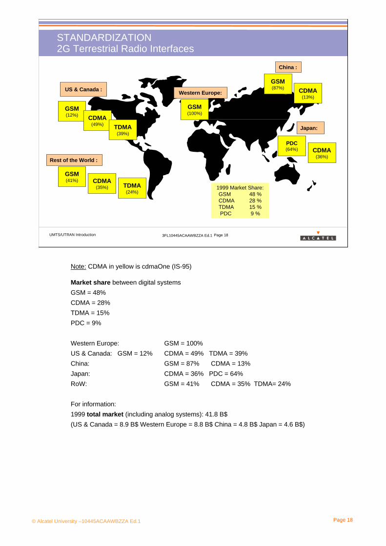
Note: CDMA in yellow is cdmaOne (IS-95)
Market share between digital systemsGSM = 48%CDMA = 28% TDMA = 15% PDC = 9%
Western Europe: GSM = 100%US & Canada: GSM = 12% CDMA = 49% TDMA = 39%China: GSM = 87% CDMA = 13%Japan: CDMA = 36% PDC = 64%RoW: GSM = 41% CDMA = 35% TDMA= 24%
For information: 1999 total market (including analog systems): 41.8 B$(US & Canada = 8.9 B$ Western Europe = 8.8 B$ China = 4.8 B$ Japan = 4.6 B$)

© Alcatel University –10445ACAAWBZZA Ed.1 Page 19
UMTS/UTRAN Introduction 3FL10445ACAAWBZZA Ed.1 Page 19
1999 Market Share:GSM 48 %CDMA 28 %TDMA 15 %PDC 9 %
UMTSCDMA2000EDGE
IMT2000
STANDARDIZATION3G Terrestrial Radio Interfaces
Western Europe:
Japan:
Rest of the World :
US & Canada :
GSM(100%)
GSM(87%) CDMA
(13%)
PDC(64%) CDMA
(36%)
GSM(12%) CDMA
(49%) TDMA(39%)
GSM(41%) CDMA
(35%) TDMA(24%)
CDMA2000
UMTS
UMTS
UMTS
UMTS
EDGE
EDGE
CDMA2000
CDMA2000
UMTS
UMTS
CDMA2000
EDGE
China :
What about Global Roaming?
ITU leads this process of harmonizing, which is necessary for a global terminal roaming and to offer operators some degree of flexibility in selecting their 3rd generation technology.
However because of different radio technologies global roaming will continue to require specific arrangements between operators, such as multi-mode and multi-band handsets and roaming gateways between the different core networks.
We can also imagine a compatibility of SIM cards instead of multi-mode handsets (ieusing a UMTS SIM card in a CDMA2000 terminal)
In fact, Global Roaming is not the issue :
The challenge is roaming and seamless services across boarders of heterogeneous private and public, fixed and mobile access networks rather than Global Roaming.
© Alcatel University –10445ACAAWBZZA Ed.1 Page 20
UMTS/UTRAN Introduction 3FL10445ACAAWBZZA Ed.1 Page 20
STANDARDIZATION3GPP: Joint Organization for UMTS Standardization
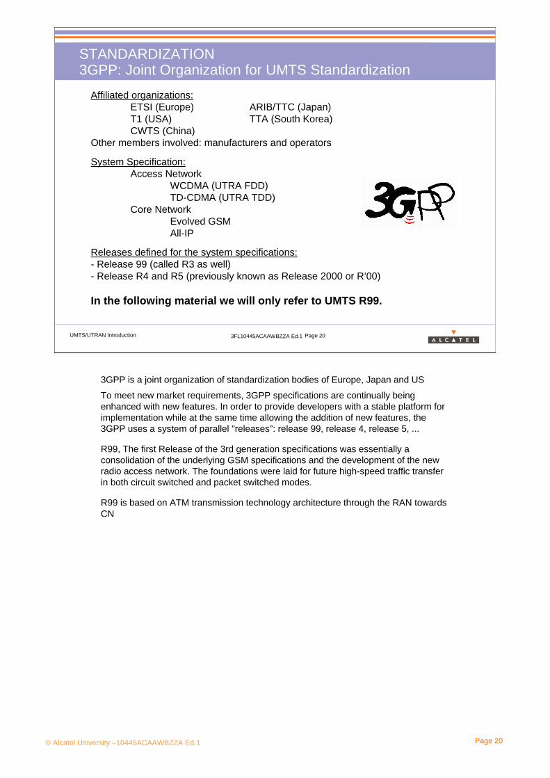
Affiliated organizations:ETSI (Europe) ARIB/TTC (Japan)T1 (USA) TTA (South Korea)CWTS (China)
Other members involved: manufacturers and operators
System Specification:Access Network
WCDMA (UTRA FDD)TD-CDMA (UTRA TDD)
Core Network Evolved GSM All-IP
Releases defined for the system specifications: - Release 99 (called R3 as well)- Release R4 and R5 (previously known as Release 2000 or R’00)
In the following material we will only refer to UMTS R99.
3GPP is a joint organization of standardization bodies of Europe, Japan and US
To meet new market requirements, 3GPP specifications are continually being enhanced with new features. In order to provide developers with a stable platform for implementation while at the same time allowing the addition of new features, the 3GPP uses a system of parallel "releases”: release 99, release 4, release 5, ...
R99, The first Release of the 3rd generation specifications was essentially a consolidation of the underlying GSM specifications and the development of the new radio access network. The foundations were laid for future high-speed traffic transfer in both circuit switched and packet switched modes.
R99 is based on ATM transmission technology architecture through the RAN towards CN

© Alcatel University –10445ACAAWBZZA Ed.1 Page 21
UMTS/UTRAN Introduction 3FL10445ACAAWBZZA Ed.1 Page 21
STANDARDIZATION 3GPP: TSG Organization
CN WG1Mobility Management,
Call Control,Session Management
CN WG2CAMEL
CN WG3Interworking with
External Networks
TSG CNCore Network
RAN WG1Radio layer 1specification
RAN WG2Radio Layer 2 &Radio Layer 3 RR
specification
RAN WG3Iub, Iur, Iu specification &
UTRAN O&M requirements
RAN WG4Radio performance &
Protocol aspects
TSG RANRadio Access Networks
SA WG1Services
SA WG2Architecture
SA WG3Security
SA WG4CODEC
SA WG5Telecom Management
TSG SAService and System
Aspects
T WG1Mobile Terminal
Conformance Testing
T WG2Mobile terminal
services & capabilities
T WG3Smart Card
Application aspects
TSG T Terminals
CN WG4MAP/GTP /BCH/SS
CN WG5OSA
Open Service Access
TSG GERAN GSM EDGE
Radio Access Network
GERAN WG1Radio Aspects
GERAN WG2Protocol Aspects
GERAN WG3Terminal Testing
Project Co-ordination Group(PCG)
3GPP is large organization, which was created in 1998.Detailed technical work is carried out in 5 Technical Specification Groups (TSG) divided into subgroups. Many people are involved: it is estimated that more than one thousand people contribute in one way or another. This is an unprecedented number of experts working on the same project.3GPP has delivered almost stable specifications, accepted by the majority of major industrial players, in only two years.

© Alcatel University –10445ACAAWBZZA Ed.1 Page 22
UMTS/UTRAN Introduction 3FL10445ACAAWBZZA Ed.1 Page 22
STANDARDIZATION 3GPP specifications
Series_Id Series_description21. Requirements22. Service Aspects23. Technical Realization24. Signaling Protocols (UE to network)25. UTRA aspects26. CODECs27. Data28. (reserved)29. Signaling Protocols (intra-fixed network)30. Program management31. User Identity Module32. O&M33. Security Aspects34. Test specification35. Security algorithms
http://www.3gpp.org/specs/specs.htm
For informationNB : the TS 21.101 lists the existing Technical Specifications for the release R 99.NB : the TS 21.102 lists the existing Technical Specifications for the release R 4.NB : the TS 21.103 lists the existing Technical Specifications for the release R 5.
© Alcatel University –10445ACAAWBZZA Ed.1 Page 23
UMTS/UTRAN Introduction 3FL10445ACAAWBZZA Ed.1 Page 23
STANDARDIZATIONUMTS Roadmap
EDGEEDGECommercialCommercialintroduction introduction
UMTS R5UMTS R5
UMTS R99UMTS R99Field TrialsField Trials
2001 20032002
GPRSGPRSimplementationimplementation
UMTS R99UMTS R99commercialcommercial
SystemSystem
2004
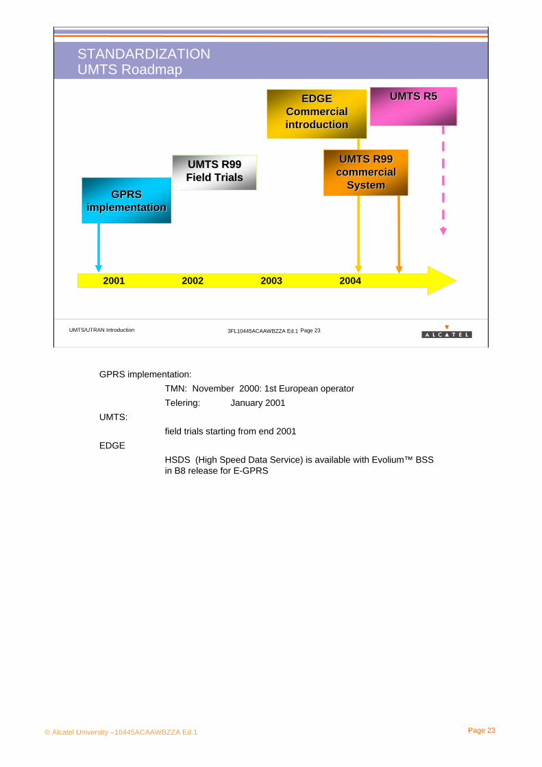
GPRS implementation:TMN: November 2000: 1st European operatorTelering: January 2001
UMTS:field trials starting from end 2001
EDGEHSDS (High Speed Data Service) is available with Evolium™ BSS in B8 release for E-GPRS

© Alcatel University –10445ACAAWBZZA Ed.1 Page 24
1. INTRODUCTION
1.3 UMTS Goals
© Alcatel University –10445ACAAWBZZA Ed.1 Page 25
UMTS/UTRAN Introduction 3FL10445ACAAWBZZA Ed.1 Page 25
UMTS GoalsWhy UMTS?
“UMTS will be a mobile communication system that offers significant user benefits including high-quality wireless multimedia services to a convergent network of fixed, cellular and satellite components.”
It will deliver information directly to users and provide them with access to new and innovative services and applications.
It will offer mobile personalized communications to the mass market regardless of location, network and terminal used.”
UMTS Forum 1997
High quality Voice (enhancement compared to GSM)Data (multimedia)
Convergence Fixed and mobile networksData and telecommunication networks (mobile phone and computer may merge)
ServicesNew, personalized, ubiquitous (but yet to be invented!)Depend on the location
•countryside and big cities •high bit rate services will be offered when standing close to the base station
Depend on the terminal•different classes of terminals according to the services the user will have
© Alcatel University –10445ACAAWBZZA Ed.1 Page 26
UMTS/UTRAN Introduction 3FL10445ACAAWBZZA Ed.1 Page 26
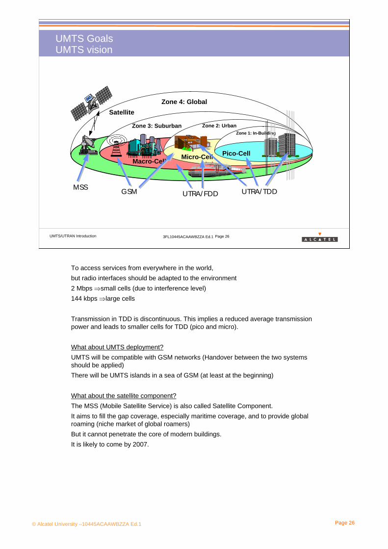
UMTS GoalsUMTS vision
Satellite
Macro-Cell Micro-Cell
Zone 2: UrbanZone 1: In-Building
Pico-Cell
Zone 4: Global
Zone 3: Suburban
UTRA/ TDDUTRA/ FDDMSS GSM
To access services from everywhere in the world,but radio interfaces should be adapted to the environment2 Mbps ⇒small cells (due to interference level)144 kbps ⇒large cells
Transmission in TDD is discontinuous. This implies a reduced average transmission power and leads to smaller cells for TDD (pico and micro).
What about UMTS deployment?UMTS will be compatible with GSM networks (Handover between the two systems should be applied)There will be UMTS islands in a sea of GSM (at least at the beginning)
What about the satellite component?The MSS (Mobile Satellite Service) is also called Satellite Component.It aims to fill the gap coverage, especially maritime coverage, and to provide global roaming (niche market of global roamers)But it cannot penetrate the core of modern buildings.It is likely to come by 2007.

© Alcatel University –10445ACAAWBZZA Ed.1 Page 27
1. INTRODUCTION
1.4 UMTS Technical Overview

© Alcatel University –10445ACAAWBZZA Ed.1 Page 28
UMTS/UTRAN Introduction 3FL10445ACAAWBZZA Ed.1 Page 28
UMTS Technical OverviewUMTS general architecture
Core network (CN)it provides support for the network features and telecommunication services. It is connected to external CS networks or PS networks.
Radio Access network (RAN)it comprises roughly the functions specific to the access technique.3 different RANs are foreseen:•UTRAN (UMTS Terrestrial RAN)•MSS (Mobile Satellite component)•BRAN (Broadband RAN)
User Equipment (UE)It is the mobile phone.
Iu
RAN
UEUu
CN Core NetworkRAN Radio Access NetworkUE User Equipment
CN
CS networks (PSTN, ISDN..)
PS networks(Internet…)
It is the same well-known architecture as the 2nd generation mobile system, but ⇒ Reconfiguration of the AN, or changes in the AN domain functionality shall have minimal impact on Core Network functions, and vice-versa.
⇒ A given Access Network (e.g., the UTRAN) may provide access to different type of Core Networks via the Iu reference point and vice versa (UTRAN, BRAN, Satellite)
That’s why we speak about Iu reference point, not about Iu interface (an interface differs from a reference point in that an interface is defined where specific information is exchanged and needs to be fully recognised)
In the following material we will not speak about MSS and BRAN, only about UTRAN.

© Alcatel University –10445ACAAWBZZA Ed.1 Page 29
UMTS/UTRAN Introduction 3FL10445ACAAWBZZA Ed.1 Page 29
UMTS Technical OverviewUMTS Cellular System
UMTS consists of a set of hierarchical cells, but the multiple access technique is completely different from GSM.
GSMUsers are separated in frequency
(FDMA) and in time (TDMA)
UMTSUsers are separated with codes
(CDMA)
© Alcatel University –10445ACAAWBZZA Ed.1 Page 30
UMTS/UTRAN Introduction 3FL10445ACAAWBZZA Ed.1 Page 30
UMTS Technical OverviewUMTS duplex modes
Downlink
UplinkFDD modeCode and Frequency
orthogonality
f1
f2
5 MHz channel
15TS
5 MHz channel
TDD modeCode and Time
orthogonality
Uplink & Downlink ......
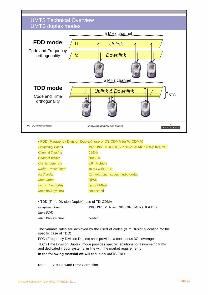
• FDD (Frequency Division Duplex): use of DS-CDMA (or W-CDMA)Frequency Bands 1920/1980 MHz (UL) / 2110/2170 MHz (DL): Region 1Channel Spacing 5 MHzChannel Raster 200 kHzCarrier chip rate 3.84 Mchip/sRadio Frame length 10 ms with 15 TSFEC codes Convolutional codes, Turbo-codesModulation QPSKBearer Capability up to 2 MbpsInter RNS synchro not needed
• TDD (Time Division Duplex): use of TD-CDMAFrequency Band 1900/1920 MHz and 2010/2025 MHz (UL&DL)Idem FDDInter RNS synchro needed
The variable rates are achieved by the used of codes (& multi-slot allocation for the specific case of TDD)FDD (Frequency Division Duplex) shall provides a continuous 3G coverage.TDD (Time Division Duplex) mode provides specific solutions for asymmetric trafficand dedicated indoor systems, in line with the market requirementsIn the following material we will focus on UMTS FDD
Note : FEC = Forward Error Correction

© Alcatel University –10445ACAAWBZZA Ed.1 Page 31
UMTS/UTRAN Introduction 3FL10445ACAAWBZZA Ed.1 Page 31
UMTS Technical OverviewUMTS Frequency allocations
TDD FDD MSS TDD1900 1980 2010 20251920
MSSFDD2110 2170 2200
FDD: Frequency Division DuplexTDD: Time Division DuplexMSS: Mobile Satellite System
Uplink Downlink
The FDD band is split into 6 licenses in Germany, into 4 in France.
MSS not allocated yet.
No band guards between operators and between TDD and FDD: it may cause problems!⇒Need for cooperation between operators

© Alcatel University –10445ACAAWBZZA Ed.1 Page 32
UMTS/UTRAN Introduction 3FL10445ACAAWBZZA Ed.1 Page 32
INTRODUCTIONQUIZ! (1)
Mark the following answers to the questions A to E by True or False.
A. What are the limits of 2G systems like GSM?
1/ No security of communications
2/ No dynamical allocation of radio resources
3/ Mobility only in a small area
4/ Heavy mobile phones
5/ Limited offer of data services
B. EDGE...
1/ is an evolution of GSM
2/ is sometimes considered as a 3G system
3/ is based on a new modulation scheme
4/ is supposed to reach a bit rate about 40 times greater than the GSM one

© Alcatel University –10445ACAAWBZZA Ed.1 Page 33
UMTS/UTRAN Introduction 3FL10445ACAAWBZZA Ed.1 Page 33
C. Which of these radio interfaces belongs to IMT-2000?
1/ CDMA One 2/ UMTS FDD 3/ UMTS TDD 4/ CDMA 2000 5/ EDGE
D. What is the organisation responsible for UMTS standardization?
1/ 3GPP 2/ 3GPP2 3/ ETSI 4/ ARIB 5/ CWTS
E. What is the bandwidth of a CDMA carrier in UMTS?
1/ 200 kHz 2/ 1 MHz 3/ 5 MHz
F. Are the following statements about UTMS duplex modes True or False?
1/ FDD is similar to the GSM duplex mode
2/ TDD use the same frequencies as FDD
3/ FDD is better suited for asymmetric traffic
4/ TDD will come later
INTRODUCTIONQUIZ! (2)

© Alcatel University –10445ACAAWBZZA Ed.1 Page 34
2. Service Provided

© Alcatel University –10445ACAAWBZZA Ed.1 Page 35
UMTS/UTRAN Introduction 3FL10445ACAAWBZZA Ed.1 Page 35
Services Provided Content> Objective: to be able to describe UMTS services , new capacity
figures and service architecture
> Program:
•• UMTS services principlesUMTS services principles•• UMTS Bearer servicesUMTS Bearer services•• TeleTele--servicesservices• UMTS Terminals

© Alcatel University –10445ACAAWBZZA Ed.1 Page 36
2. Service Provided
2.1 UMTS Services Principles

© Alcatel University –10445ACAAWBZZA Ed.1 Page 37
UMTS/UTRAN Introduction 3FL10445ACAAWBZZA Ed.1 Page 37
UMTS Service PrinciplesWhat is a service?
E.g speech, file transfer,emails...
E.g data transfer at 9,6 kbps, intransparent mode, with turbocode...
UTRAN CN CNGateway
TE
UMTS Bearer Service External BearerService
UMTS Bearer Service
Radio Access Bearer Service(RAB)
CN BearerService
BackboneBearer Service
Iu BearerService
Radio BearerService
Radio Physical Bearer Service
PhysicalBearer Service
Uu Iu
Teleservice
... ...
TE/MT Node
Basic telecommunication services are divided in two broad categories:
- bearer services: provide the capability of transmission of signals between access points. They are related to lower layers.
- tele-services: provide the complete capability, including terminal equipment functions, for communication between users. They are related to higher layers.
Examples:
- Bearer services: transmission at 9,6 kbps with a max BER of 10-3. This service can not be used alone, it needs protocols of upper layers to be controlled and relayed.
-Tele-services: file transfer (the bit rate transfer depends not only on the bearer service but also on the application)
See 3GPP23.107

© Alcatel University –10445ACAAWBZZA Ed.1 Page 38
UMTS/UTRAN Introduction 3FL10445ACAAWBZZA Ed.1 Page 38
UMTS Services PrinciplesTele-services and Bearer services
TeleservicesSpeech, emergency calls
SMSEmailInternet Access
Mobile e-commerceVideo PostcardsInformation and location based services
New applications
UMTS Bearer servicesLarge toolkit for all kinds of services
“Instinctive” service
Basic services
Enhanced services
New services to be provided by service providers (third party)
Whereas 2G mobile systems offer mainly speech services (the content is provided by the user), UMTS has to support a wide range of applications with different quality of services.
New Services: we can also imagine that the customer himself will be able to create its own new services (easy access ways to create services)
UMTS bearer services shall provide the necessary capabilities to support multimedia services and to enable the user of a single terminal to establish and maintain several connections simultaneously.
3GPP shall standardise service capabilities (bearer services) and not the services (teleservices) themselves.
© Alcatel University –10445ACAAWBZZA Ed.1 Page 40
UMTS/UTRAN Introduction 3FL10445ACAAWBZZA Ed.1 Page 40
UMTS Services PrinciplesVirtual Home Environment (VHE)
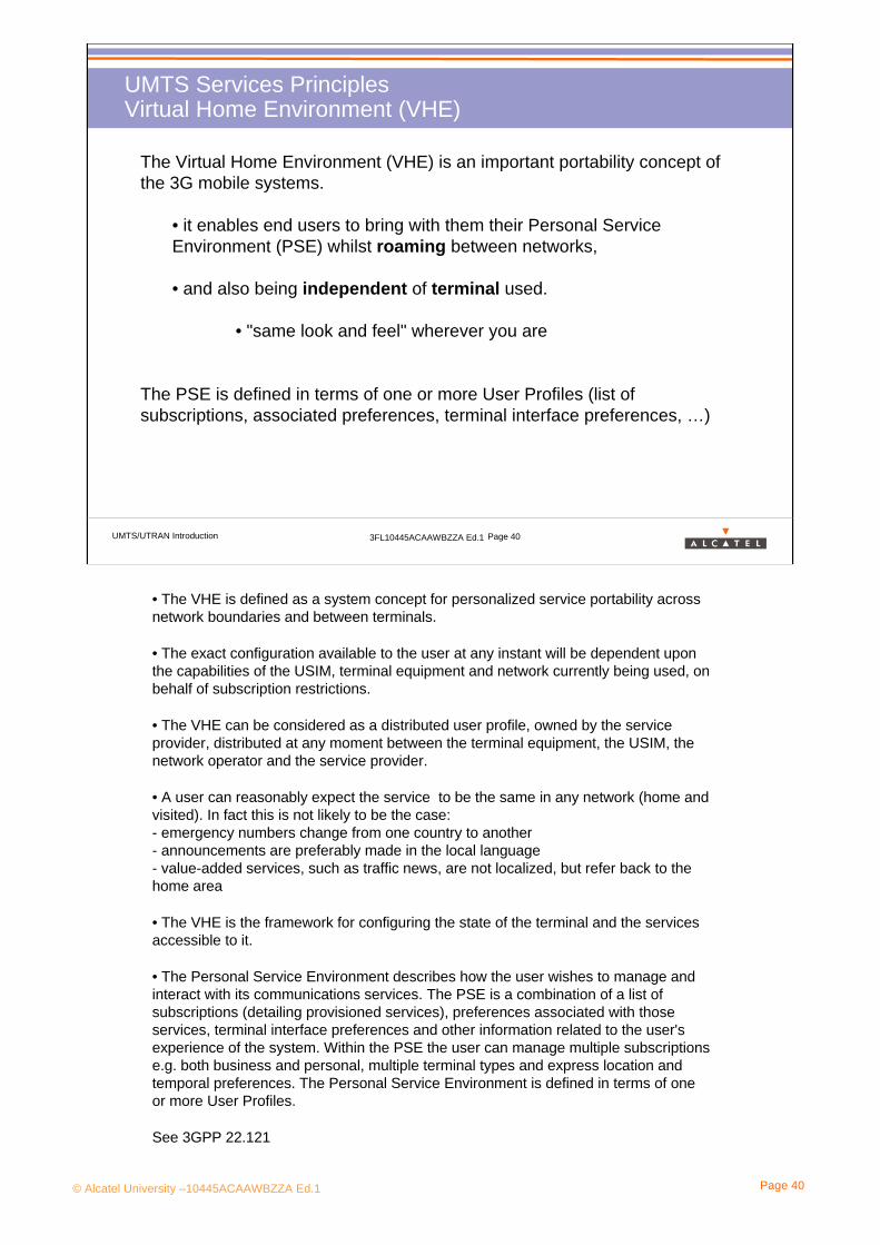
The Virtual Home Environment (VHE) is an important portability concept of the 3G mobile systems.
• it enables end users to bring with them their Personal Service Environment (PSE) whilst roaming between networks,
• and also being independent of terminal used.
• "same look and feel" wherever you are
The PSE is defined in terms of one or more User Profiles (list of subscriptions, associated preferences, terminal interface preferences, …)
• The VHE is defined as a system concept for personalized service portability across network boundaries and between terminals.
• The exact configuration available to the user at any instant will be dependent upon the capabilities of the USIM, terminal equipment and network currently being used, on behalf of subscription restrictions.
• The VHE can be considered as a distributed user profile, owned by the service provider, distributed at any moment between the terminal equipment, the USIM, the network operator and the service provider.
• A user can reasonably expect the service to be the same in any network (home and visited). In fact this is not likely to be the case:- emergency numbers change from one country to another- announcements are preferably made in the local language- value-added services, such as traffic news, are not localized, but refer back to the home area
• The VHE is the framework for configuring the state of the terminal and the services accessible to it.
• The Personal Service Environment describes how the user wishes to manage and interact with its communications services. The PSE is a combination of a list of subscriptions (detailing provisioned services), preferences associated with those services, terminal interface preferences and other information related to the user's experience of the system. Within the PSE the user can manage multiple subscriptions e.g. both business and personal, multiple terminal types and express location and temporal preferences. The Personal Service Environment is defined in terms of one or more User Profiles.
See 3GPP 22.121

© Alcatel University –10445ACAAWBZZA Ed.1 Page 41
UMTS/UTRAN Introduction 3FL10445ACAAWBZZA Ed.1 Page 41
UMTS Services PrinciplesService Architecture
VHE concept is based on the standard mechanisms of Service Capability Servers which allow Service Capability Features. The latter are carried through standard interfaces in order to support Tele-services adapted to the Service Capabilities of the network and user equipment.
Service Layer
Service Capability Features
SATCAMEL MExEService Capability Servers GSM/GPRS/UMTS
Standardizedinterfaces
Network Layer
Tele-services(terminal equipment functions,Operator transmission capabilities)
Bearer Services
Fixed
VHE defines Service Capability Servers and standardises the features.Services capabilities:•Service capabilities are based on functionality and mechanisms /toolkits such as provided by SAT, MExE, IN and CAMEL. These service capabilities can be made visible to the applications through an application interface.Service Capability Servers:•GSM/GPRS/UMTS bearer services: they offer mechanisms for applications to access basic bearer capabilities. •MExE (Mobile Execution Environment) servers: Value added services are offered through a client/server relationship between the MExE server in the network and the Mobile Execution Environment (e.g. Java Virtual Machine or WAP browser) in the terminal (TS 22.057)•SAT (SIM Application Toolkit) servers: mechanisms that offer additional capabilities to the communication protocol between smart card and mobile station (TS 22.004)• CAMEL (Customised Application for Mobile networks Enhanced Logic) servers: CAMEL extends the scope of IN services provisioned to the mobile environment (TS 23.078)Service Capability Features•Functionality offered by service capabilities that are accessible via the standardised application interface. Examples: Call Control, Location/Positioning, PLMN Information & Notifications
Bearer Services:The service characteristics as they apply at a given reference point where the user accesses the bearer service.
© Alcatel University –10445ACAAWBZZA Ed.1 Page 42
UMTS/UTRAN Introduction 3FL10445ACAAWBZZA Ed.1 Page 42
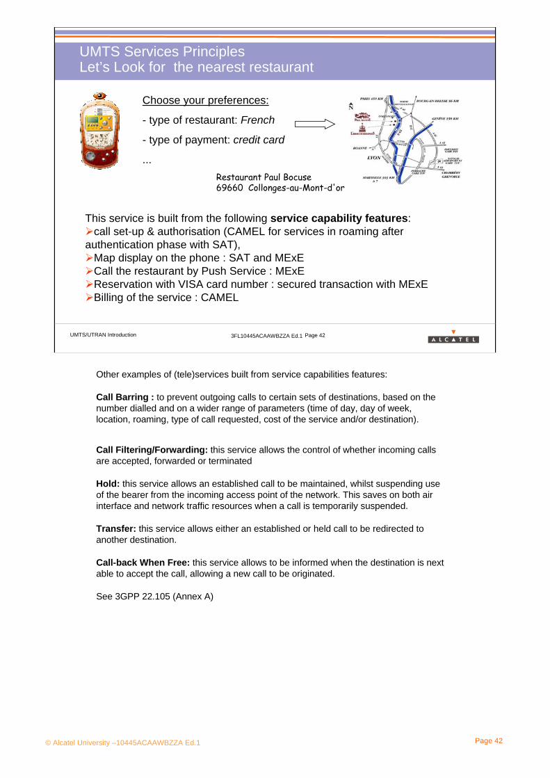
UMTS Services PrinciplesLet’s Look for the nearest restaurant
Choose your preferences:
- type of restaurant: French
- type of payment: credit card
...
This service is built from the following service capability features: call set-up & authorisation (CAMEL for services in roaming after
authentication phase with SAT),Map display on the phone : SAT and MExECall the restaurant by Push Service : MExEReservation with VISA card number : secured transaction with MExEBilling of the service : CAMEL
Restaurant Paul Bocuse69660 Collonges-au-Mont-d'or
Other examples of (tele)services built from service capabilities features:
Call Barring : to prevent outgoing calls to certain sets of destinations, based on the number dialled and on a wider range of parameters (time of day, day of week, location, roaming, type of call requested, cost of the service and/or destination).
Call Filtering/Forwarding: this service allows the control of whether incoming calls are accepted, forwarded or terminated
Hold: this service allows an established call to be maintained, whilst suspending use of the bearer from the incoming access point of the network. This saves on both air interface and network traffic resources when a call is temporarily suspended.
Transfer: this service allows either an established or held call to be redirected to another destination.
Call-back When Free: this service allows to be informed when the destination is next able to accept the call, allowing a new call to be originated.
See 3GPP 22.105 (Annex A)

© Alcatel University –10445ACAAWBZZA Ed.1 Page 43
2. Service Provided
2.2 UMTS Bearer Services

© Alcatel University –10445ACAAWBZZA Ed.1 Page 44
UMTS/UTRAN Introduction 3FL10445ACAAWBZZA Ed.1 Page 44
UMTS BEARER SERVICESBearer Services Characterization
Bearer services are characterized by a set of end-to-end characteristics with requirements on QoS, always considered point-to-point.Bearer services provide the capability for information transfer between access points and involve only low layer functions.
Each bearer service is characterized by its requirements:• transfer information: connection oriented or connectionless, traffic type (guaranteed/constant bit rate, non guaranteed/variable…), traffic characteristics (uni-directional, bi-directional, multicast…), priority• quality characteristics: maximum transfer delay, delay variation, bit error ratio, data rate.
This set of requirements are called QoS parameters. Example : several active radio bearer services can be handled simultaneously by the same terminal equipment.
See 3GPP TS 22.105
QoS: Quality of Service
PS and CS domains provide a specific set of bearer capabilities.
© Alcatel University –10445ACAAWBZZA Ed.1 Page 45
UMTS/UTRAN Introduction 3FL10445ACAAWBZZA Ed.1 Page 45
UMTS BEARER SERVICESBearer QoS Requirements
• negotiable: QoS offer on demand
• provide a wide range of QoS levels
• dynamic behaviour: It shall be possible to negotiate (re-negotiate) the characteristics of a bearer service at session or connection establishment (during an on going session or connection).
• support of asymmetric nature between uplink and downlink
• supply of bearer services without wasting resources on the radio and network interfaces.

© Alcatel University –10445ACAAWBZZA Ed.1 Page 46
UMTS/UTRAN Introduction 3FL10445ACAAWBZZA Ed.1 Page 46
UMTS BEARER SERVICESBearer Supported Bit Rates
The only limiting factor for satisfying application requirements shall be the cumulative bit rate per mobile termination at a given instant in each radio environment:
•At least 144 kbps in rural outdoor radio environment (with a maximum speed of 500 km/h)•At least 384 kbps in urban or suburban outdoor radio environments (with a maximum speed of 120 km/h)
•At least 2048 kbps in indoor or low range outdoor radio environment (with a maximum speed of 10 km/h)
Theses performances decrease:- when the speed of the user increases- when the load of the network increases
The bit rate target have been specified according to the Integrated Services Digital Network (ISDN):- the 144 Kbps data rate provides the ISDN 2B+D channel- the 384 Kbps provides the ISDN H0 Channel- the 1920 Kbps provides the ISDN H12 Channel(even though 2Mbps is generally used as the upper limit for IMT-2000 services, the exact service is specified to be 1.92 or 2.048 Mbps)
Several backward compatibility requirements influence the technology applied to 3G systems.
See 3GPP TS 22.105
© Alcatel University –10445ACAAWBZZA Ed.1 Page 47
2. Service Provided
2.3 Tele-services
© Alcatel University –10445ACAAWBZZA Ed.1 Page 48
UMTS/UTRAN Introduction 3FL10445ACAAWBZZA Ed.1 Page 48
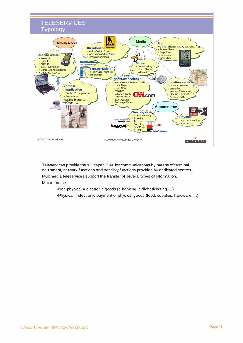
TELESERVICESTypology
Location services• Traffic Conditions• Itineraries• Nearest Restaurant,
Cinema, Chemist, Parking;, ATM ...
Fun• Games (Hangman, Poker, Quiz, …)• Screen Saver• Ring Tone• Horoscope• Biorhythm
MediaAlways-on
M-commerce
Mobile Office• Voice (!)• E-mail• Agenda• IntraNet/InterNet• Corporate Applications• Database Access
Transportation• Flight/train Schedule• reservation
Vertical application
• Traffic Management• Automation• Mobile branches • Health
Music• Downloading of
music files orvideo clips
News(general/specific)• International/National News• Local News• Sport News• Weather• Lottery Results• Finance News• Stock Quotes• Exchange Rates
Physical• on-line shopping• on-line food
Non physical• on-line Banking• Ticketing• Auction• Gambling• Best Price• e-Book
Directories• Yellow/White Pages• International Directories• Operator Services
Teleservices provide the full capabilities for communications by means of terminal equipment, network functions and possibly functions provided by dedicated centres.Multimedia teleservices support the transfer of several types of information.M-commerce :
•Non-physical = electronic goods (e-banking, e-flight ticketing, ...)•Physical = electronic payment of physical goods (food, supplies, hardware, ...)
© Alcatel University –10445ACAAWBZZA Ed.1 Page 49
UMTS/UTRAN Introduction 3FL10445ACAAWBZZA Ed.1 Page 49
TELESERVICESQoS classes
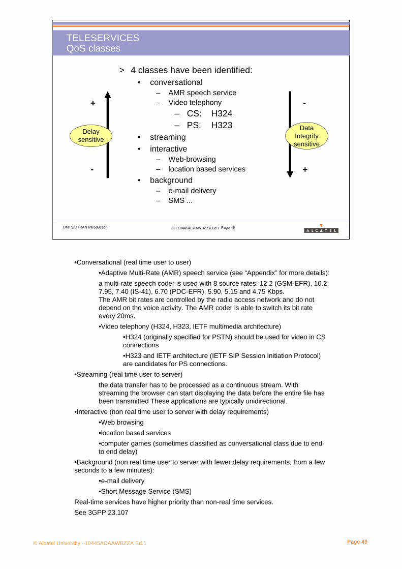
> 4 classes have been identified:• conversational
– AMR speech service – Video telephony
– CS: H324– PS: H323
• streaming• interactive
– Web-browsing– location based services
• background– e-mail delivery– SMS ...
Delay sensitive
+
-
Data Integritysensitive
-
+
•Conversational (real time user to user)•Adaptive Multi-Rate (AMR) speech service (see “Appendix” for more details):a multi-rate speech coder is used with 8 source rates: 12.2 (GSM-EFR), 10.2, 7.95, 7.40 (IS-41), 6.70 (PDC-EFR), 5.90, 5.15 and 4.75 Kbps.The AMR bit rates are controlled by the radio access network and do not depend on the voice activity. The AMR coder is able to switch its bit rate every 20ms.•Video telephony (H324, H323, IETF multimedia architecture)
•H324 (originally specified for PSTN) should be used for video in CS connections•H323 and IETF architecture (IETF SIP Session Initiation Protocol) are candidates for PS connections.
•Streaming (real time user to server)the data transfer has to be processed as a continuous stream. With streaming the browser can start displaying the data before the entire file has been transmitted These applications are typically unidirectional.
•Interactive (non real time user to server with delay requirements)•Web browsing•location based services•computer games (sometimes classified as conversational class due to end-to end delay)
•Background (non real time user to server with fewer delay requirements, from a few seconds to a few minutes):
•e-mail delivery •Short Message Service (SMS)
Real-time services have higher priority than non-real time services.See 3GPP 23.107

© Alcatel University –10445ACAAWBZZA Ed.1 Page 50
UMTS/UTRAN Introduction 3FL10445ACAAWBZZA Ed.1 Page 50
TELESERVICESPerformance
QoS of teleservices depends not only on UMTS network, but also on applications, terminals and external networks.From a user’s perspective it is more relevant to speak of delay rather than bit rate:
Errortolerant
Errorintolerant
Conversationaldelay <<1 sec
Interactivedelay<1 secStreaming
delay <10 secBackgrounddelay >10 sec
Conversationalvoice and video
Streaming audioand video Fax
E-mail arrivalnotification
E-commerce,WWW browsingTelnet,
interactive gamesFTP, still image,
paging
Voice messaging
Conversational speech
Audio transfer delay requirements depends on the level of interactivity of the end users. To preclude difficulties related to the dynamics of voice communications, ITU-T Recommendation G.114 recommends the following general limits for one-way transmission time (assuming echo control already taken care of):
0 to 150 ms preferred range
150 to 400 ms acceptable range (but with quality decreasing)
above 400 ms unacceptable range
Interactive games
Requirements for interactive games are obviously very dependent on the specific game, but it is clear that demanding applications will require very short delays, and a value of 250 ms is proposed, consistent with demanding interactive applications.
Web-browsing
In this category we will refer to retrieving and viewing the HTML component of a Web page, other components like images, audio/video clips are related to separate QoSClasses. From the user point of view, the main performance factor is how fast a page appears after it has been requested. A value of 2-4 seconds per page is proposed, however improvement on these figures to a target figure of 0.5 seconds would be desirable.
Delay values represent one -way delay (i.e. from originating entity to terminating entity).
See 3GPP TS 22.105 Annex B

© Alcatel University –10445ACAAWBZZA Ed.1 Page 51
UMTS/UTRAN Introduction 3FL10445ACAAWBZZA Ed.1 Page 51
TELESERVICESDefining Charging Principles
• How will billing be performed: by time? by volume? by number ofconnections?
• If billing is performed by volume, what will be an easy way to explain to the customer what a “1 Mbyte of data” is?
• What will happen in case of handover between GSM and UMTS?
• What about roaming? Prepaid services?
• QoS depends directly on the load of the network. A trade-off must be found between users. Customers who pay more might have higher priority or better QoS (depending of the operator’s strategies). Billing for a given service might depend on the QoS.
From 3GPP TS 22.115

© Alcatel University –10445ACAAWBZZA Ed.1 Page 52
UMTS/UTRAN Introduction 3FL10445ACAAWBZZA Ed.1 Page 52
TELESERVICESLocation based services
Teleservices will depend on the strategy and on the imagination of operators and content providers.
The key point is likely to be a fast access to information and an appropriate filtering of the user location data.
the UMTS killer application is likely be a location based service
Example of location based services : look for an hotel, consult yellow pages, get local traffic situation or weather report,...
Limitation: location information could be a risk for privacy.
At the moment UMTS specifies that it will provide location information to an accuracy of 50m. Different positioning methods are specified in R’99 such as:
•the cell coverage-based positioning method•Observed Time Difference Of Arrival-Idle Period Down-Link (OTDOA-IPDL)•network-assisted GPS methods
3GPP TS 22.071, TS 24.030
© Alcatel University –10445ACAAWBZZA Ed.1 Page 53
UMTS/UTRAN Introduction 3FL10445ACAAWBZZA Ed.1 Page 53
2.12.1 UMTS service principlesUMTS service principles
2.22.2 UMTS Bearer servicesUMTS Bearer services
2.32.3 TeleTele--servicesservices
2.42.4 UMTS Terminals UMTS Terminals
SERVICE PROVIDED

© Alcatel University –10445ACAAWBZZA Ed.1 Page 54
2. Service Provided
2.4 UMTS Terminals

© Alcatel University –10445ACAAWBZZA Ed.1 Page 39
UMTS/UTRAN Introduction 3FL10445ACAAWBZZA Ed.1 Page 39
UMTS Services Principles Third party: service provider
Tele-services will not be standardised so as to differentiate betweenoperators and providers of applications.UMTS offer new opportunity for content and service providers
Today’s 1:1 customer-operator relationship
Tomorrow’s situation?
OperatorContracted Content providers
Contracted Service providers
Contracted Service providers
Operator
Existing systems have largely standardised the complete sets of tele-services, applications and supplementary services which they provide. As a consequence, substantial re-engineering is often required to enable new services to be provided. In addition, the market for services is largely determined by operators and standardization. This makes it more difficult for operators to differentiate their services.
This is the reason why tele-services should not be standardized : to motivate competition between new actors of the telecommunication market, i.e content providers.
Today, it is hardly possible to predict the nature and the usage of most applications, as UMTS ought to be generic by nature to allow good support of existing applications and to ease the evolution of new applications.

© Alcatel University –10445ACAAWBZZA Ed.1 Page 55
UMTS/UTRAN Introduction 3FL10445ACAAWBZZA Ed.1 Page 55
UMTS TERMINALSUser Equipment (UE)
User Equipment (UE)
Cuinterface
Mobile Equipment
(ME)
UICCUSIM
USIM 2
1
GSMaccess
SIM
GSM/GPRS terminal
Functionally speaking, the User Equipment (UE) is composed of the Mobile Equipment (ME) and the UMTS Subscriber Identity Module (USIM).The Role of USIM is very similar to that of the SIM in GSM:- it is used to store subscriber identity, subscription data, authentication and ciphering keys, authentication algorithms - its security is improved compared to GSM with a mutual authentication between the card and the network.The interface between ME and USIM is the Cu interface, the importance of which is crucial for compatibility: even if full multi-mode Terminals will not be developed (in a first period at least), USIM-roaming will allow the subscriber to use different IMT2000 terminals with the same card.The UICC (UMTS integrated Circuit Card) is similar to SIM card in GSM with the same size (either ISO or plug-in).It may contain one or several USIM for different applications and also the SIM module in order to be used in a GSM terminal .Another possibility is to include additional mechanisms in the USIM part in order to provide the GSM access and be usable in a multi-mode UMTS/GSM terminal.
TS 21.111: USIM and IC card requirements
© Alcatel University –10445ACAAWBZZA Ed.1 Page 56
UMTS/UTRAN Introduction 3FL10445ACAAWBZZA Ed.1 Page 56
UMTS TERMINALSRange of Terminals
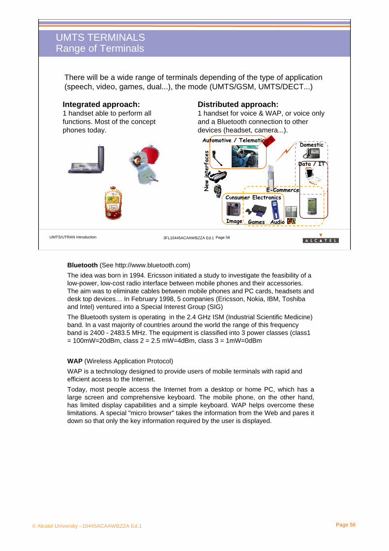
There will be a wide range of terminals depending of the type of application (speech, video, games, dual...), the mode (UMTS/GSM, UMTS/DECT...)
Consumer Electronics
Games AudioImage
Automotive / Telematics
New
int
erfa
ces
Data / IT
E-Commerce
DomesticGPS
Integrated approach:1 handset able to perform all functions. Most of the concept phones today.
Distributed approach:1 handset for voice & WAP, or voice only and a Bluetooth connection to other devices (headset, camera...).
Bluetooth (See http://www.bluetooth.com) The idea was born in 1994. Ericsson initiated a study to investigate the feasibility of a low-power, low-cost radio interface between mobile phones and their accessories. The aim was to eliminate cables between mobile phones and PC cards, headsets and desk top devices… In February 1998, 5 companies (Ericsson, Nokia, IBM, Toshiba and Intel) ventured into a Special Interest Group (SIG)The Bluetooth system is operating in the 2.4 GHz ISM (Industrial Scientific Medicine) band. In a vast majority of countries around the world the range of this frequency band is 2400 - 2483.5 MHz. The equipment is classified into 3 power classes (class1 = 100mW=20dBm, class 2 = 2.5 mW=4dBm, class 3 = 1mW=0dBm
WAP (Wireless Application Protocol) WAP is a technology designed to provide users of mobile terminals with rapid and efficient access to the Internet.Today, most people access the Internet from a desktop or home PC, which has a large screen and comprehensive keyboard. The mobile phone, on the other hand, has limited display capabilities and a simple keyboard. WAP helps overcome these limitations. A special "micro browser" takes the information from the Web and pares it down so that only the key information required by the user is displayed.

© Alcatel University –10445ACAAWBZZA Ed.1 Page 57
UMTS/UTRAN Introduction 3FL10445ACAAWBZZA Ed.1 Page 57
SERVICES PROVIDEDQUIZ!
A. True or False? The tele-services...
1/ are used for example to make a call, to access yellow pages, on-line banking...
2/ are mapped on bearer services
3/ will be standardized by 3GPP
B. True of False? The VHE...
1/ is a portability concept of 3G mobile systems
2/ will enable to keep the same environment when roaming between mobile and fixed networks
3/ will be adapted to the terminal capabilities
4/ will use proprietary interfaces

© Alcatel University –10445ACAAWBZZA Ed.1 Page 58
UMTS/UTRAN Introduction 3FL10445ACAAWBZZA Ed.1 Page 58
C. True or False? A bearer service can support for one user:
1/ 2 Mbps at a speed of 120 km/h
2/ 2 Mbps in a high loaded cell
3/ 2 Mbps at 3 km away from the base station
4/ Asymmetric traffic
5/ Variable traffic
D. True or False? Location based services...
1/ are services only available in some areas (city centers...)
2/ are services related to the location of the user
3/ can locate the mobile phone with an accuracy of about 50 m
SERVICES PROVIDEDQUIZ!

© Alcatel University –10445ACAAWBZZA Ed.1 Page 59
UMTS/UTRAN Introduction 3FL10445ACAAWBZZA Ed.1 Page 59
E. True or False? A UICC (UMTS integrated Circuit Card)...
1/ has the same size as a GSM SIM card
2/ can not be used in a GSM terminal
3/ can be used in an UMTS terminal and provide access to GSM network
4/ is linked with the UMTS terminal via a proprietary interface
5/ may provide access to UMTS networks of different operators
F. UMTS services have been announced to come later than initially scheduled because of non availability of UMTS terminals in volume: can you find some reasons which makes it quite complex to design UMTS terminals?
SERVICES PROVIDEDQUIZ!

© Alcatel University –10445ACAAWBZZA Ed.1 Page 60
3. UMTS System Description

© Alcatel University –10445ACAAWBZZA Ed.1 Page 61
UMTS/UTRAN Introduction 3FL10445ACAAWBZZA Ed.1 Page 61
3. UMTS System Description Section presentation> Objective: to be able to draw the UTRAN architecture with the
protocol stack (radio and Iu) of each Network element and to define the channels generated by these protocols.
> Program: • 3.1 Logical Architecture• 3.2 Network Protocols• 3.3 UTRAN Channels• 3.4 UTRAN Radio Protocols

© Alcatel University –10445ACAAWBZZA Ed.1 Page 62
3. UMTS System Description
3.1 Logical Architecture
© Alcatel University –10445ACAAWBZZA Ed.1 Page 63
UMTS/UTRAN Introduction 3FL10445ACAAWBZZA Ed.1 Page 63
Logical ArchitectureUTRAN Situation & Core Network in 3GPP R4
Core Network
PSCN
Access Network
Iu-PS
External Networks
HLR
PSTN
IN network
UTRAN
RNCRNC
Node B
PDN
CS Links PS Links
GbBackbone AlcateAlcate
lliGGSNiGGSN
SGSNGSMBSS
BSC
BTS PCU
CSCNMSC Server
MGWGMSC
Iu-CS
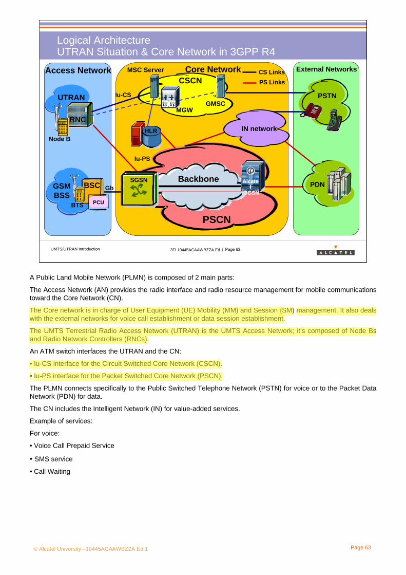
A Public Land Mobile Network (PLMN) is composed of 2 main parts:
The Access Network (AN) provides the radio interface and radio resource management for mobile communications toward the Core Network (CN).
The Core network is in charge of User Equipment (UE) Mobility (MM) and Session (SM) management. It also deals with the external networks for voice call establishment or data session establishment.
The UMTS Terrestrial Radio Access Network (UTRAN) is the UMTS Access Network; it’s composed of Node Bs and Radio Network Controllers (RNCs).
An ATM switch interfaces the UTRAN and the CN:
• Iu-CS interface for the Circuit Switched Core Network (CSCN).
• Iu-PS interface for the Packet Switched Core Network (PSCN).
The PLMN connects specifically to the Public Switched Telephone Network (PSTN) for voice or to the Packet Data Network (PDN) for data.
The CN includes the Intelligent Network (IN) for value-added services.
Example of services:
For voice:
• Voice Call Prepaid Service
• SMS service
• Call Waiting

© Alcatel University –10445ACAAWBZZA Ed.1 Page 64
UMTS/UTRAN Introduction 3FL10445ACAAWBZZA Ed.1 Page 64
Logical Architecture UTRAN Logical Architecture
Core Network
UTRAN
UE
Iub Iub
Iu-CS Iu-PS
Iur
Uu Interface
RNS
CNCS CNPS
RNC RNC
Node B Node B
CN2 separated domains: Circuit Switched (CS) and Packet Switched (PS) which reuse the infrastructure of GSM and GPRS respectively.
UTRAN- new radio interface: CDMA- new transmission technology: ATM
CN independent of ANThe specificity of the access network due to mobile system should be transparent to the core network, which may potentially use any access technique. Radio specificity of the access network is hidden to the core network.UE radio mobility is fully controlled by UTRAN.
Some correspondences with GSM:CN NSS Uu UmUTRAN BSS Iub A-bisRNC BSC Iur no equivalentNode-B BTS Iu-CS AUE MS Iu-PS Gb
© Alcatel University –10445ACAAWBZZA Ed.1 Page 65
UMTS/UTRAN Introduction 3FL10445ACAAWBZZA Ed.1 Page 65
Logical Architecture Interfaces
Open Interfaces:
• The function of the Network Elements have been clearly specified by the 3GPP.•Their internal implementations issues are open for the manufacturer• All the interfaces have been defined in such a detailed level that the equipment at the endpoints can be from different manufacturers.
•“Open Interfaces” aim at motivating competition between manufacturers.
Physical implementation of Iu interfaces•Each Iu Interface may be implemented on any physical connection using any transport technology, mainly on E1 (cable), STM1 (Optic fiber) and micro-waves.•ATM will be provided in the 3GPP R4 release and IP is foreseen for the 3GPP R6
A manufacturer can produce only the Node-B (and not the RNC). This is not possible in GSM (A-bis is a proprietary interface)
The Iur physical connection can go through the CN using common physical links with Iu-CS and Iu-PS. However there is a direct logical connection between the 2 RNCs: the Iur information is not handled by the CN.

© Alcatel University –10445ACAAWBZZA Ed.1 Page 66
UMTS/UTRAN Introduction 3FL10445ACAAWBZZA Ed.1 Page 66
Logical ArchitectureNetwork Element Function
RNC: Radio Network ControllerIt is the intelligent part of the UTRAN:
-Radio resource management (code allocation, Power Control, congestion control, admission control)- Call management for the users- Connection to CS and PS Core Network- Radio mobility management
Iub IubIur
RNSNode B Node B
RNC RNC
An RNS (Radio Network Subsystem) contains one RNC (Radio Network Controller) and at least one Node-B.
The RNC takes a more important place in UTRAN than the BSC in the GSM BSS. Indeed RNC can perform soft HO, while in GSM there is no connection between BSCs and only hard HO can be applied.
© Alcatel University –10445ACAAWBZZA Ed.1 Page 67
UMTS/UTRAN Introduction 3FL10445ACAAWBZZA Ed.1 Page 67
Logical ArchitectureNetwork Element Function
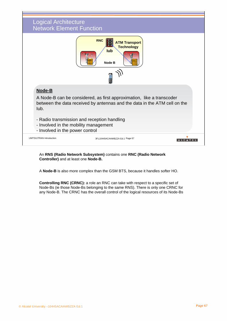
Node-BA Node-B can be considered, as first approximation, like a transcoder between the data received by antennas and the data in the ATM cell on the Iub.
- Radio transmission and reception handling- Involved in the mobility management- Involved in the power control
Iub
RNC
Node B
ATM Transport Technology
An RNS (Radio Network Subsystem) contains one RNC (Radio Network Controller) and at least one Node-B.
A Node-B is also more complex than the GSM BTS, because it handles softer HO.
Controlling RNC (CRNC): a role an RNC can take with respect to a specific set of Node-Bs (ie those Node-Bs belonging to the same RNS). There is only one CRNC for any Node-B. The CRNC has the overall control of the logical resources of its Node-Bs

© Alcatel University –10445ACAAWBZZA Ed.1 Page 68
3. UMTS System Description
3.2 Network Protocols

© Alcatel University –10445ACAAWBZZA Ed.1 Page 69
UMTS/UTRAN Introduction 3FL10445ACAAWBZZA Ed.1 Page 69
Network ProtocolsProtocols in UTRAN
Uu Interface
Core Network
RNC RNC
Node B
Iub
Iu
Iur
Iu Protocols
> The Iu protocols• Used to exchange data
(traffic and signaling) between RNCs, Node Bs and the Core Network.
Radio Protocols
> The Radio protocols• Used to process the
data sent on the air and for the signaling between UTRAN and the UEs
> NAS Signaling• Signaling between a
UE and the Core Network.
• Typically, the Authentification and the Location NAS Signaling
Iu Protocols : RANAP: Radio Access Network Application Protocol,RNSAP: Radio Network Sub-system Application Protocol,NBAP: Node B Application Protocol,ALCAP is a generic name for the signalling protocols of the Transport Network Control Plane used to establish/release Data Bearers.It makes establishment/release of Data Bearers on request of the Application Protocol.
Radio Protocols :RRC: Radio Resource ControlRLC: Radio Link ControlMAC: Medium Access Control
NAS refers to higher layers (3 to 7). Entities of this part will exchange tele-services
and bearer services.

© Alcatel University –10445ACAAWBZZA Ed.1 Page 70
UMTS/UTRAN Introduction 3FL10445ACAAWBZZA Ed.1 Page 70
Network ProtocolsProtocol Stack on the Interfaces
Iub
Iub
Iur
Iu- PS
Iu- CS
Node B
RNC
RNC
RNSAP
RANAP
RANAP
Iu UPVoice
Iur FP
Iu UPData
Control plane User plane
Iub
Node B
Node B
CS-CN
PS-CN
RadioSig Voice
NBAPIub FP
RadioSig Voice Data
AAL5 AAL2ATM
AAL5 AAL2ATM
AAL5 AAL2ATM
AAL5 AAL5ATM
Data
AAL5 has been designed to adapt non real time, connectionless oriented data at variablebit rate (eg, web browsing) to ATM.AAL2 has been designed to adapt real time, connection oriented data at variable bit rate(eg, voice in AMR) to ATM.
© Alcatel University –10445ACAAWBZZA Ed.1 Page 71
UMTS/UTRAN Introduction 3FL10445ACAAWBZZA Ed.1 Page 71
Network ProtocolsGeneral model
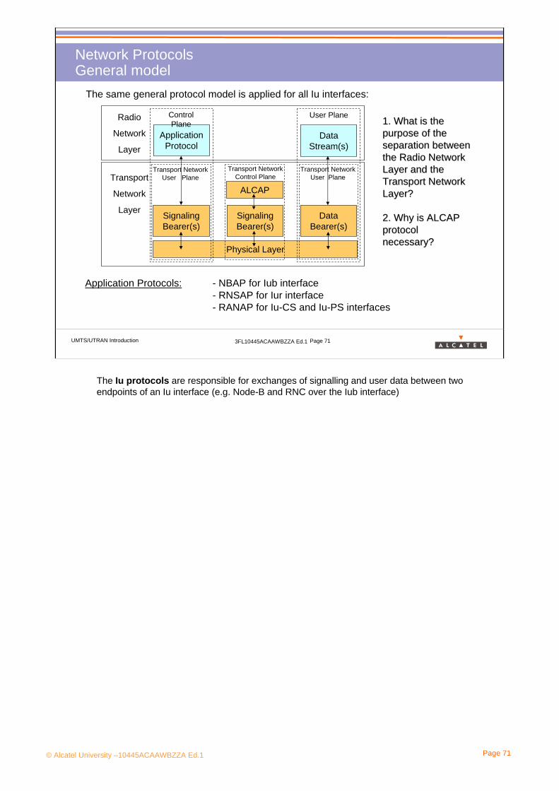
The same general protocol model is applied for all Iu interfaces:
Application Protocols:
Radio
Network
Layer
Transport
Network
Layer
Physical Layer
SignalingBearer(s)
SignalingBearer(s)
DataBearer(s)
ALCAP
ApplicationProtocol
DataStream(s)
Transport Network Control Plane
Transport Network User Plane
Transport Network User Plane
Control Plane
User Plane
- NBAP for Iub interface- RNSAP for Iur interface- RANAP for Iu-CS and Iu-PS interfaces
1. What is the 1. What is the purpose of the purpose of the separation between separation between the Radio Network the Radio Network Layer and the Layer and the Transport Network Transport Network Layer?Layer?
2. Why is ALCAP 2. Why is ALCAP protocol protocol necessary?necessary?
The Iu protocols are responsible for exchanges of signalling and user data between two endpoints of an Iu interface (e.g. Node-B and RNC over the Iub interface)

© Alcatel University –10445ACAAWBZZA Ed.1 Page 72
UMTS/UTRAN Introduction 3FL10445ACAAWBZZA Ed.1 Page 72
Network ProtocolsIub protocols
ATM
Radio
Network
Layer
Transport
Network
Layer
Physical Layer
AAL5 AAL2
ALCAP
NBAPFrame
Protocols(IubFP)
Control Plane User Plane
AAL5
RRC Connection Establishment*
Radio Link Establishment RABs*
NAS signalling*
Transport Network Control Plane
Transport Network User Plane
Transport Network User Plane
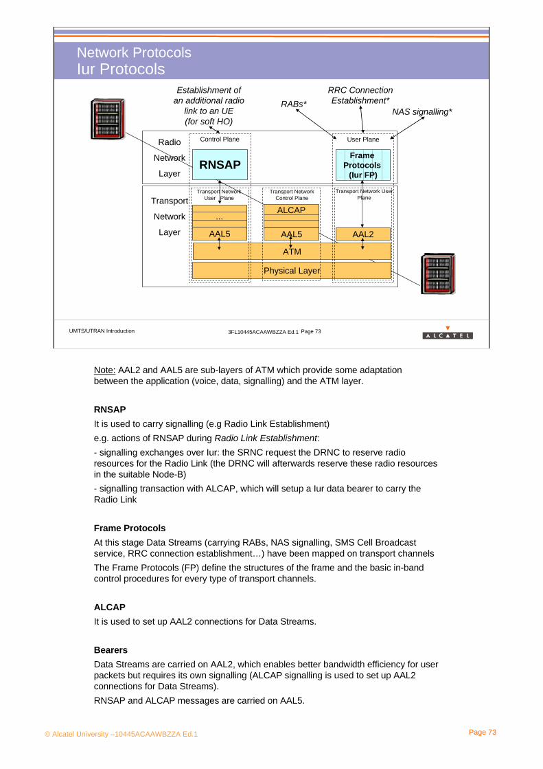
Note: AAL2 and AAL5 are sub-layers of ATM which provide some adaptation between the application (voice, data, signalling) and the ATM layer.
NBAPis used to carry signalling (e.g Radio Link Establishment) Examples of actions of NBAP during Radio Link Establishment:- signalling exchanges over Iub, which permits the RNC to reserve radio resources of Node-B for the Radio Link- signalling transaction with ALCAP, which will setup a Iub data bearer (on AAL2) to carry the Radio Link
Frame ProtocolsAt this stage Data Streams (carrying RABs, NAS signalling, SMS Cell Broadcast service, RRC connection establishment…) have been mapped on transport channels The Frame Protocols (FP) define the structures of the frame and the basic in-band control procedures for every type of transport channels.
ALCAPis used to set up AAL2 connections for Data Streams.
BearersData Streams are carried on AAL2, which enables better bandwidth efficiency for user packets but requires its own signalling (ALCAP signalling is used to set up AAL2 connections for Data Streams).NBAP and ALCAP messages are carried on AAL5.
© Alcatel University –10445ACAAWBZZA Ed.1 Page 73
UMTS/UTRAN Introduction 3FL10445ACAAWBZZA Ed.1 Page 73
Network ProtocolsIur Protocols
ATM
Radio
Network
Layer
Transport
Network
Layer
Physical Layer
...
AAL5 AAL2
ALCAP
RNSAPFrame
Protocols (Iur FP)
Control Plane User Plane
AAL5
RRC Connection Establishment*
Establishment of an additional radio
link to an UE (for soft HO)
RABs*NAS signalling*
Transport Network Control Plane
Transport Network User Plane
Transport Network User Plane
Note: AAL2 and AAL5 are sub-layers of ATM which provide some adaptation between the application (voice, data, signalling) and the ATM layer.
RNSAPIt is used to carry signalling (e.g Radio Link Establishment) e.g. actions of RNSAP during Radio Link Establishment:- signalling exchanges over Iur: the SRNC request the DRNC to reserve radio resources for the Radio Link (the DRNC will afterwards reserve these radio resources in the suitable Node-B)- signalling transaction with ALCAP, which will setup a Iur data bearer to carry the Radio Link
Frame ProtocolsAt this stage Data Streams (carrying RABs, NAS signalling, SMS Cell Broadcast service, RRC connection establishment…) have been mapped on transport channels The Frame Protocols (FP) define the structures of the frame and the basic in-band control procedures for every type of transport channels.
ALCAPIt is used to set up AAL2 connections for Data Streams.
BearersData Streams are carried on AAL2, which enables better bandwidth efficiency for user packets but requires its own signalling (ALCAP signalling is used to set up AAL2 connections for Data Streams).RNSAP and ALCAP messages are carried on AAL5.
© Alcatel University –10445ACAAWBZZA Ed.1 Page 74
UMTS/UTRAN Introduction 3FL10445ACAAWBZZA Ed.1 Page 74
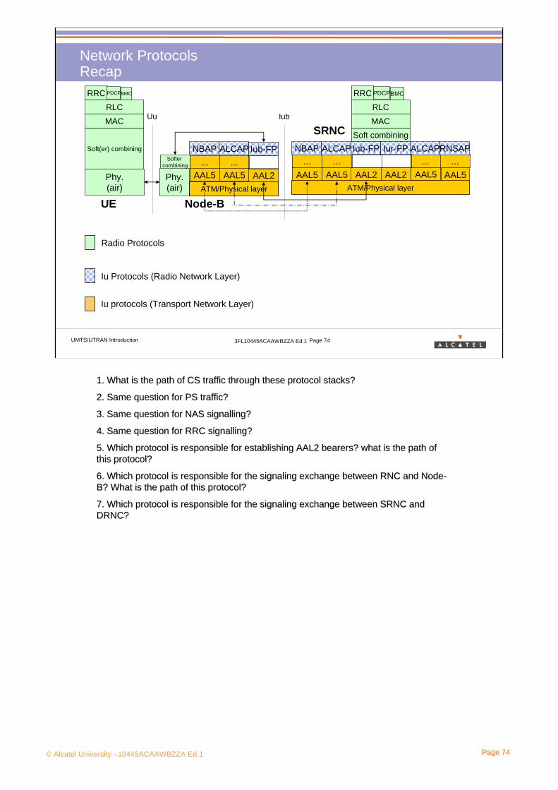
AAL5 AAL2 AAL2 AAL5 AAL5AAL5AAL5 AAL5 AAL2Phy.(air)
Phy.(air) ATM/Physical layer ATM/Physical layer
... ...NBAP ALCAP
... ...NBAP ALCAP
Soft combining
... ...ALCAPRNSAPIub-FP Iur-FP
MAC
RLC
RRC PDCPBMC
Soft(er) combining
MAC
RLC
RRC PDCPBMC
UE Node-B
SRNC
Softer combining
Iub
Iub-FP
Uu
Radio Protocols
Iu Protocols (Radio Network Layer)
Iu protocols (Transport Network Layer)
Network ProtocolsRecap
1. What is the path of CS traffic through these protocol stacks?1. What is the path of CS traffic through these protocol stacks?
2. Same question for PS traffic?2. Same question for PS traffic?
3. Same question for NAS signalling?3. Same question for NAS signalling?
4. Same question for RRC signalling?4. Same question for RRC signalling?
5. Which protocol is responsible for establishing AAL2 bearers? 5. Which protocol is responsible for establishing AAL2 bearers? what is the path of what is the path of this protocol?this protocol?
6. Which protocol is responsible for the signaling exchange betw6. Which protocol is responsible for the signaling exchange between RNC and Nodeeen RNC and Node--B? What is the path of this protocol?B? What is the path of this protocol?
7. Which protocol is responsible for the signaling exchange betw7. Which protocol is responsible for the signaling exchange between SRNC and een SRNC and DRNC?DRNC?
© Alcatel University –10445ACAAWBZZA Ed.1 Page 75
UMTS/UTRAN Introduction 3FL10445ACAAWBZZA Ed.1 Page 75
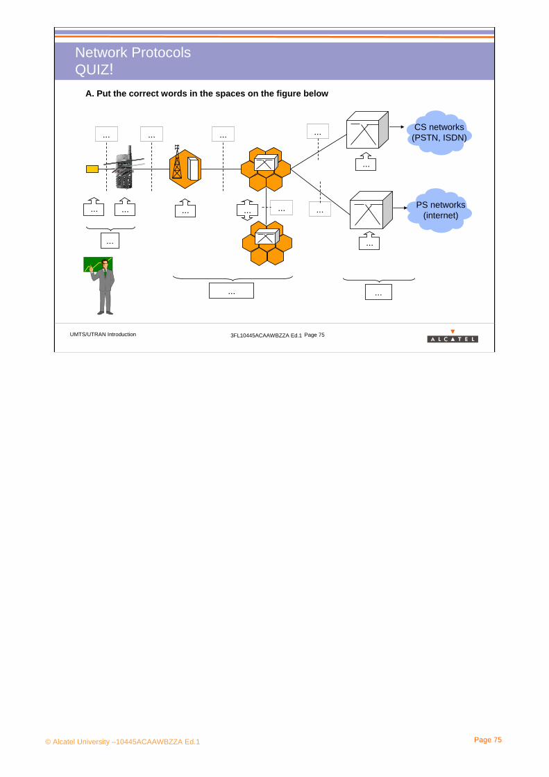
Network ProtocolsQUIZ!
A. Put the correct words in the spaces on the figure below
... ... ...
...
...
... ... ... ...
......
...
... ...
CS networks (PSTN, ISDN)
PS networks (internet)...

© Alcatel University –10445ACAAWBZZA Ed.1 Page 76
3. UMTS System Description
3.3 Radio Channels
© Alcatel University –10445ACAAWBZZA Ed.1 Page 77
UMTS/UTRAN Introduction 3FL10445ACAAWBZZA Ed.1 Page 77
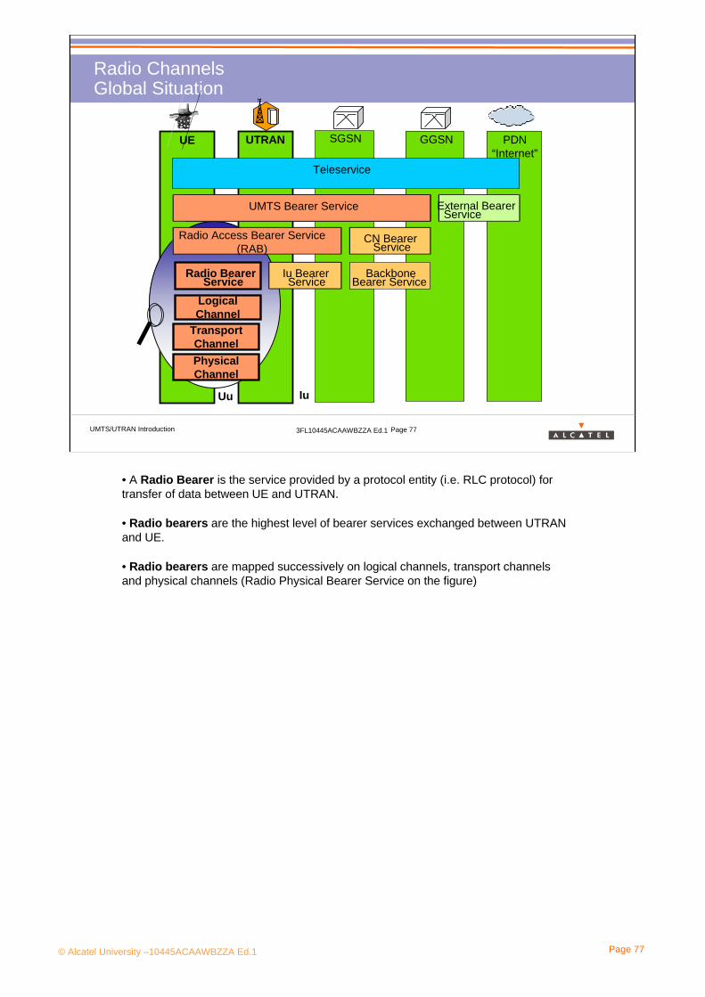
Radio Channels Global Situation
UTRAN SGSN GGSN PDN“Internet”
UMTS Bearer Service External BearerService
UMTS Bearer Service
Radio Access Bearer Service(RAB)
CN BearerService
BackboneBearer Service
Iu BearerService
Radio BearerService
Uu Iu
Teleservice
UE
Logical Channel
Transport ChannelPhysicalChannel
• A Radio Bearer is the service provided by a protocol entity (i.e. RLC protocol) for transfer of data between UE and UTRAN.
• Radio bearers are the highest level of bearer services exchanged between UTRAN and UE.
• Radio bearers are mapped successively on logical channels, transport channelsand physical channels (Radio Physical Bearer Service on the figure)
© Alcatel University –10445ACAAWBZZA Ed.1 Page 78
UMTS/UTRAN Introduction 3FL10445ACAAWBZZA Ed.1 Page 78
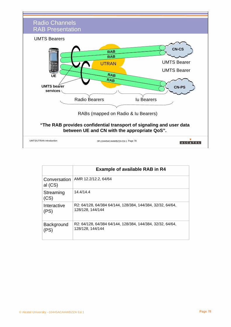
Radio ChannelsRAB Presentation
“The RAB provides confidential transport of signaling and user data between UE and CN with the appropriate QoS”.
UTRAN
UEUMTS Bearer
UMTS Bearers
RABs (mapped on Radio & Iu Bearers)
CN-CS
CN-PS
Radio Bearers Iu Bearers
RABRAB
RABRAB
UMTS Bearer
UMTS bearer services
AMR 12.2/12.2, 64/64Conversational (CS)
R2: 64/128, 64/384 64/144, 128/384, 144/384, 32/32, 64/64, 128/128, 144/144
Background (PS)
14.4/14.4Streaming (CS)
Example of available RAB in R4
R2: 64/128, 64/384 64/144, 128/384, 144/384, 32/32, 64/64, 128/128, 144/144
Interactive (PS)

© Alcatel University –10445ACAAWBZZA Ed.1 Page 79
UMTS/UTRAN Introduction 3FL10445ACAAWBZZA Ed.1 Page 79
Radio ChannelsRadio Channels, Protocols & Network Elements
RRC
RLC
MAC
BMCPDCP
Physical Layer Physical Layer
NAS Signaling
RRC Sig.
Voice Web Browsing
SMS Cell Broadcast
Radio Bearers
Control Logical Ch.
Traffic Logical Ch.
…Transport Channels
Uu Interface
RNC Node B UE
Physical Channels
MAC
…
Transport Channels
The radio protocols are responsible for exchanges of signalling and user data between the UE and the UTRAN over the Uu interface:-User plane protocolsThese are the protocols implementing the actual Radio Access Bearer (RAB) service,
-i.e. carrying user data through the access stratum (EXAMPLES 1,2 and 4).
-Control plane protocolsThese are the protocols for controlling the radio access bearers and the connection
-between the UE and the network from different aspects including requesting the service
(EXAMPLE 5), controlling different transmission resources, handover & streamlining etc...
Also a mechanism for transparent transfer of Non Access Stratum (NAS) messages is included).
Some principles:
•The Radio Protocols are independent of the applied transport layer technology (ATM in R99): that may be changed in the future while the Radio Protocols remain intact.•The main part of radio protocols are located in the RNC (and in the UE). The Node-B is mainly a relay between UE and RNC.

© Alcatel University –10445ACAAWBZZA Ed.1 Page 80
UMTS/UTRAN Introduction 3FL10445ACAAWBZZA Ed.1 Page 80
Radio ChannelsRadio Bearers
Signalling Radio Bearers (SRB)
SRBs can carry:- layer 3 signalling (e.g. RRC connection establishment)- NAS signalling (e.g location update)
There can be up to 4 SRBs per RRC connection (one UE has one RRC connection when connected to the UTRAN).
User Plane Radio Bearers
RABs are mapped on user plane RBs.
One RAB can be divided on RAB sub-flows and each sub-flow is mapped on one user plane RB.
e.g the AMR codec encodes/decodes speech into/from three sub-flows; each sub-flow can have its own channel coding.
Please note that RAB (Radio Access Bearer) are only provided in the user plane.
What is a RRC connection?When the UE needs to exchange any information with the network, it must first establish a signalling link with the UTRAN: it is made through a procedure with the RRC protocol and it is called “RRC connection establishment”. During this procedure the UE will send an initial access request on CCCH to establish a signalling link which will be carried on a DCCH.A given UE can have either zero or one RRC connection.

© Alcatel University –10445ACAAWBZZA Ed.1 Page 81
UMTS/UTRAN Introduction 3FL10445ACAAWBZZA Ed.1 Page 81
Radio ChannelsLogical Channels (1)
Control Channels (CCH)
Broadcast Control Channel (BCCH)
Traffic Channels (TCH)
Paging Control Channel (PCCH)
Dedicated Control Channel (DCCH)
Common Control Channel (CCCH)
Dedicated Traffic Channel (DTCH)
Common Traffic Channel (CTCH)
UTRAN UELogical Channels
The logical channels are divided into:
•Control channels for the transfer of control plane information
•Traffic channels for the transfer of user plane information

© Alcatel University –10445ACAAWBZZA Ed.1 Page 82
UMTS/UTRAN Introduction 3FL10445ACAAWBZZA Ed.1 Page 82
Radio ChannelsLogical Channels (2)
UL ( )/
DL ( )What type of information?
BCCH System control informatione.g cell identity, uplink interference level
PCCH Paging informatione.g CN originated call when the network does not know thelocation cell of the UE
CCCH Control informatione.g initial access (RRC connection request), cell update
DCCH Control information (but the UE must have a RRC connection)e.g radio bearer setup, measurement reports, HO
DTCH Traffic information dedicated to one UEe.g speech, fax, web browsing
CTCH Traffic information to all or a group of UEse.g SMS-Cell Broadcast

© Alcatel University –10445ACAAWBZZA Ed.1 Page 83
UMTS/UTRAN Introduction 3FL10445ACAAWBZZA Ed.1 Page 83
Radio ChannelsWhy Transport Channels?
A transport channel offers a flexible pattern to arrange information on any service-specific rate, delay or coding before mapping it on a physical channel:• it provides flexibility in traffic variation• it enables multiplexing of transport channels on the same physical channel
Transport channels provide an efficient and fast flexibility in radio resource management.
Time
Traffic
Time IntervalTransport Channel
© Alcatel University –10445ACAAWBZZA Ed.1 Page 84
UMTS/UTRAN Introduction 3FL10445ACAAWBZZA Ed.1 Page 84
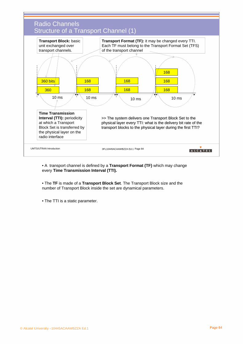
Radio ChannelsStructure of a Transport Channel (1)
168
168
168
168
168
360
360 bits
10 ms
Time Transmission Interval (TTI): periodicity at which a Transport Block Set is transferred by the physical layer on the radio interface
10 ms
Transport Block: basic unit exchanged over transport channels.
Transport Format (TF): it may be changed every TTI. Each TF must belong to the Transport Format Set (TFS) of the transport channel
168
168
>> The system delivers one Transport Block Set to the >> The system delivers one Transport Block Set to the physical layer every TTIphysical layer every TTI: what is the delivery bit rate of the : what is the delivery bit rate of the transport blocks to the physical layer during the first TTI?transport blocks to the physical layer during the first TTI?
10 ms 10 ms
• A transport channel is defined by a Transport Format (TF) which may change every Time Transmission Interval (TTI).
• The TF is made of a Transport Block Set. The Transport Block size and the number of Transport Block inside the set are dynamical parameters.
• The TTI is a static parameter.

© Alcatel University –10445ACAAWBZZA Ed.1 Page 85
UMTS/UTRAN Introduction 3FL10445ACAAWBZZA Ed.1 Page 85
Radio ChannelsStructure of a Transport Channel (2)
Transport Format (TF)• Semi-static part (can be changed, but long process)
Transmission Time Interval (TTI),Coding scheme...
• Dynamic part (may be changed easily) Size of transport block, Number of transport blocks per TTI
Transport Format Set (TFS)It is the set of allowed Transport Formats for a transport channel, which is assigned by RRC protocol entity to MAC protocol entity.MAC chooses TF among TFS.MAC may choose another TF every TTI without interchanging with RRC protocol (fast radio resource control).
What is TTI (Transmission Time Interval)?
- it is equal to the periodicity at which a Transport Block Set is transferred by the physical layer on the radio interface
- it is always a multiple of the minimum interleaving period (e.g. 10ms, the length of one Radio Frame)
- MAC delivers one Transport Block Set to the physical layer every TTI.
© Alcatel University –10445ACAAWBZZA Ed.1 Page 86
UMTS/UTRAN Introduction 3FL10445ACAAWBZZA Ed.1 Page 86
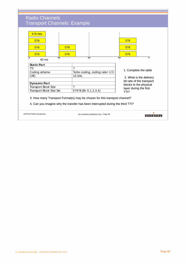
Radio ChannelsTransport Channels: Example
576
576
576
576
576
576
576 bits
576
576
40 ms
3. How many Transport Format(s) may be chosen for this transport3. How many Transport Format(s) may be chosen for this transport channel?channel?
4. Can you imagine why the transfer has been interrupted during 4. Can you imagine why the transfer has been interrupted during the third TTI? the third TTI?
Static PartTTI ?Coding scheme Turbo coding, coding rate= 1/ 3CRC 16 bits
Dynamic PartTransport Block Size ?Transport Block Size Set 576*B (B= 0,1,2,3,4)
1. Complete the table1. Complete the table
2.2. What is the delivery What is the delivery bit rate of the transport bit rate of the transport blocks to the physical blocks to the physical layer during the first layer during the first TTI?TTI?

© Alcatel University –10445ACAAWBZZA Ed.1 Page 87
UMTS/UTRAN Introduction 3FL10445ACAAWBZZA Ed.1 Page 87
Radio ChannelsTransport Channels
Common Channels
Broadcast Channel (BCH)
Dedicated Channels
Paging Channel (PCH)
Random Access Channel (RACH)
Forward Access Channel (FACH)
Dedicated Channel (DCH)
Common Packet Channel (CPCH)
Downlink Shared Channel (DSCH)
UTRAN Transport Channels UE
The transport channels are divided into:
•Common channels: they are divided between all or a group of UEs in a cell. They require in-band identification of the UEs when addressing particular UEs.
•Dedicated channels: it is reserved for a single UE only. In-band identification is not necessary, a given UE is identified by the physical channel (code and frequency in FDD mode)
© Alcatel University –10445ACAAWBZZA Ed.1 Page 88
UMTS/UTRAN Introduction 3FL10445ACAAWBZZA Ed.1 Page 88
Radio ChannelsCommon Transport Channels (1)
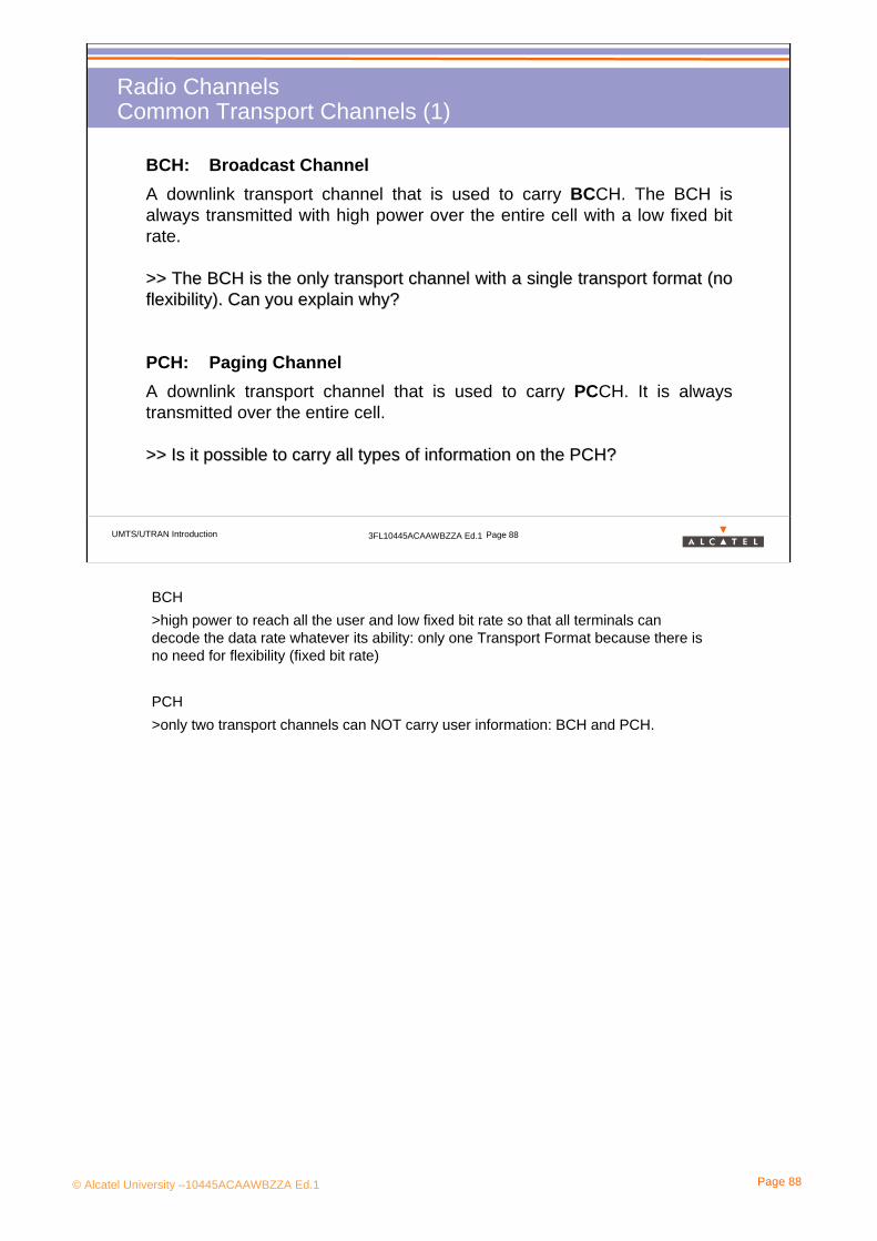
BCH: Broadcast ChannelA downlink transport channel that is used to carry BCCH. The BCH is always transmitted with high power over the entire cell with a low fixed bit rate.
>> The BCH is the only transport channel with a single transport>> The BCH is the only transport channel with a single transport format (no format (no flexibility). Can you explain why?flexibility). Can you explain why?
PCH: Paging ChannelA downlink transport channel that is used to carry PCCH. It is always transmitted over the entire cell.
>> Is it possible to carry all types of information on the PCH?>> Is it possible to carry all types of information on the PCH?
BCH >high power to reach all the user and low fixed bit rate so that all terminals can decode the data rate whatever its ability: only one Transport Format because there is no need for flexibility (fixed bit rate)
PCH>only two transport channels can NOT carry user information: BCH and PCH.

© Alcatel University –10445ACAAWBZZA Ed.1 Page 89
UMTS/UTRAN Introduction 3FL10445ACAAWBZZA Ed.1 Page 89
Radio ChannelsCommon Transport Channels (2)
FACH: Forward Access ChannelA downlink transport channel that is used to carry control information. It may also carry short users packets. The FACH is transmitted over the entire cell or over only a part of the cell using beam-forming antennas. The FACH uses open loop power control (slow power control).
>> In which case is it interesting to use beam>> In which case is it interesting to use beam--forming antennas? would it also be forming antennas? would it also be relevant to implement this feature for PCH?relevant to implement this feature for PCH?
RACH: Random Access ChannelAn uplink transport channel that is used to carry control information from the mobile especially at the initial access. It may also carry short user packets. The RACH is always received from the entire cell and is characterized by a limited size data field, a collision risk and by the use of open loop power control (slow power control).
>> Why is it interesting to carry short user packets on RACH in >> Why is it interesting to carry short user packets on RACH in spite of limited data spite of limited data field and collision risk (instead of using a dedicated channel)?field and collision risk (instead of using a dedicated channel)?
Note: Beam-forming is also called “Inherent addressing of users”: it is the possibility of transmission to a certain part of the cell.
RACH and FACH are mainly used to carry signalling (e.g at the initial access), but they can also carry small amounts of data.
When a UE sends information on the RACH, it will receive information on FACH.

© Alcatel University –10445ACAAWBZZA Ed.1 Page 90
UMTS/UTRAN Introduction 3FL10445ACAAWBZZA Ed.1 Page 90
Radio ChannelsCommon Transport Channels (3)
DSCH: Downlink Shared ChannelA downlink transport channel shared by several UEs to carry dedicated control or user information. When a UE is using the DSCH, it always has an associated DCH, which provides power control.
CPCH: Common Packet ChannelAn uplink transport channel that is used to carry long user data packets and control packets. It is a contention based random access channel. It is always associated with a dedicated channel on the downlink, which provides power control.
⇒ Transfer of signalling and traffic on a shared basis
DSCH and CCPH seem to be symmetrical, but:
- DSCH is on the DL, so that different user data are synchronised with each other (the information on whether the UE should receive the DSCH or not is conveyed on the associated DCH)
- CPCH is on the UL, so that different user data can NOT be synchronised (the mobile phones are not synchronised). It may cause big problem of collisions!

© Alcatel University –10445ACAAWBZZA Ed.1 Page 91
UMTS/UTRAN Introduction 3FL10445ACAAWBZZA Ed.1 Page 91
Radio ChannelsDedicated Transport Channels
DCH: Dedicated ChannelA downlink or uplink transport channel that is used to carry user or control information. It is characterized by features such as fast rate change (on a frame-by-frame basis), fast power control, use of beam-forming and support of soft HO.
DCH > It is different from GSM where TCH carries user data (e.g speech frames) and ACCH carries higher layer signalling (e.g HO commands)User data and signalling are therefore treated in the same way from the physical layer (although set of parameters may be different between data and signalling)
> wide range of Transport Format Set permits to be very flexible concerning the bit rate, the interleaving...
> Fast Power Control and soft HO are only applied on this transport channel.
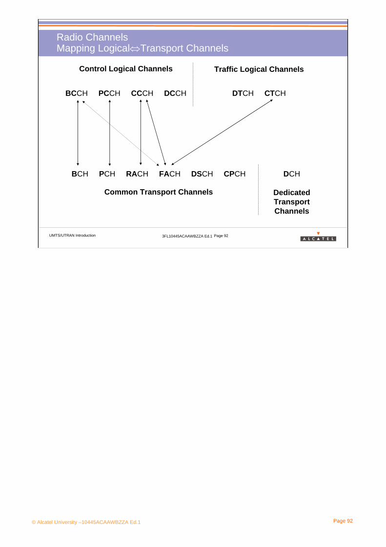
© Alcatel University –10445ACAAWBZZA Ed.1 Page 92
UMTS/UTRAN Introduction 3FL10445ACAAWBZZA Ed.1 Page 92
Radio ChannelsMapping Logical⇔Transport Channels
Control Logical Channels
BCCH PCCH CCCH DCCH
Traffic Logical Channels
DTCH CTCH
BCH PCH RACH FACH DSCH CPCH DCH
Common Transport Channels Dedicated Transport Channels
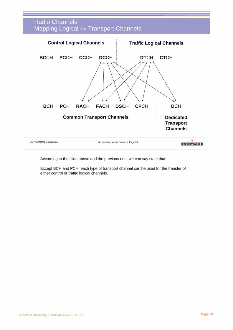
© Alcatel University –10445ACAAWBZZA Ed.1 Page 93
UMTS/UTRAN Introduction 3FL10445ACAAWBZZA Ed.1 Page 93
Radio ChannelsMapping Logical ⇔ Transport Channels
Control Logical Channels
BCCH PCCH CCCH DCCH
Traffic Logical Channels
DTCH CTCH
BCH PCH RACH FACH DSCH CPCH DCH
Common Transport Channels Dedicated Transport Channels
According to the slide above and the previous one, we can say state that :
Except BCH and PCH, each type of transport channel can be used for the transfer of either control or traffic logical channels.
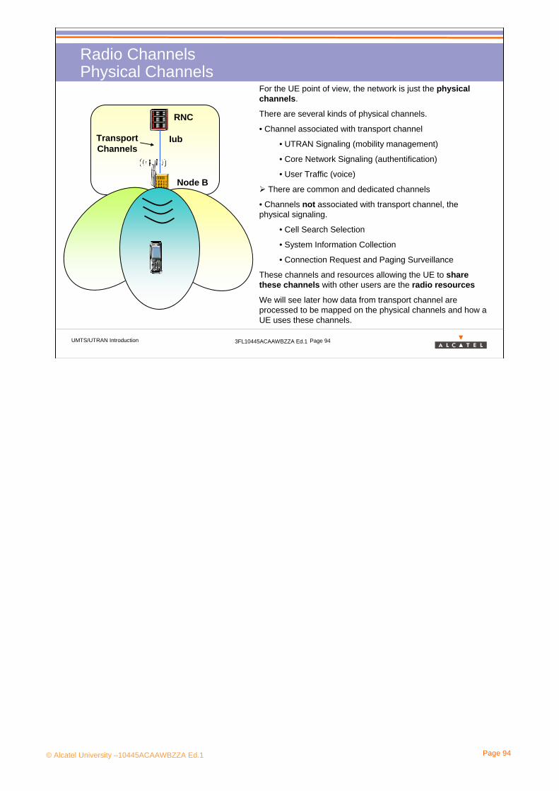
© Alcatel University –10445ACAAWBZZA Ed.1 Page 94
UMTS/UTRAN Introduction 3FL10445ACAAWBZZA Ed.1 Page 94
Radio ChannelsPhysical Channels
RNC
Node B
IubTransport Channels
For the UE point of view, the network is just the physical channels.
There are several kinds of physical channels.
• Channel associated with transport channel
• UTRAN Signaling (mobility management)
• Core Network Signaling (authentification)
• User Traffic (voice)
There are common and dedicated channels
• Channels not associated with transport channel, the physical signaling.
• Cell Search Selection
• System Information Collection
• Connection Request and Paging Surveillance
These channels and resources allowing the UE to share these channels with other users are the radio resources
We will see later how data from transport channel are processed to be mapped on the physical channels and how a UE uses these channels.

© Alcatel University –10445ACAAWBZZA Ed.1 Page 95
UMTS/UTRAN Introduction 3FL10445ACAAWBZZA Ed.1 Page 95
Radio Channels MappingPhysical Channel List
Not associated with transport channels
• CPICH: Common Pilot Channel
• PICH: Page Indicator Channel
• P-SCH & S-SCH: Primary & Secondary Synchronization Channel
• AICH: Acquisition Indicator Channel
Common Physical Channels, associated with transport channels
• P-CCPCH & S-CCPCH: Primary & Secondary Common Control Channel
• PRACH: Physical Random Access Channel
• PDSCH: Physical Downlink Shared Channel
• PCPCH: Physical Common Packet Channel
Dedicated Physical Channels, associated with transport channels
• DPDCH: Dedicated Physical Data Channel
• DPCCH: Dedicated Physical Control Channel

© Alcatel University –10445ACAAWBZZA Ed.1 Page 96
UMTS/UTRAN Introduction 3FL10445ACAAWBZZA Ed.1 Page 96
Radio ChannelsPhysical Channels: Structure
15 Time Slots
Radio Frame = 10 ms
N bits (according to the bit rate)
….
1 Time slot = 0.666 ms
A physical channel is defined by:
•A carrier• Some codes (see 4.3 and 4.4 part)• A start and stop instant
Physical channels are sent continuously on the air interface between start and stop instants.
•After channel coding each transport block is split into radio frames of 10 ms.The bit rate may be changed for each frame.
• Each radio frame is also split into 15 time slots. But all time slots belong to the same user (this slot structure has nothing to do with the TDMA structure in GSM).All time slots of a same TDMA frame have the same bit rate.Fast power control may be performed for each time slot (1500 Hz).
• The number of chips for one bit M is equivalent to the spreading factor. It can easilybe computed with knowledge of N:
In fact the spreading factor must be equal to 4, 8, 16…256.Consequently it may be necessary to add some padding bits to match the adequate valueof spreading factor (rate matching).
© Alcatel University –10445ACAAWBZZA Ed.1 Page 97
3. UMTS System Description
3.4 UTRAN Radio Protocols

© Alcatel University –10445ACAAWBZZA Ed.1 Page 98
UMTS/UTRAN Introduction 3FL10445ACAAWBZZA Ed.1 Page 98
Radio ProtocolsRadio protocol stack
Layer 3
Control plane User plane
Layer 2/MAC
Layer 1Transport Channels
Bearers (called RAB in user plane)Access Stratum
SAP
Non Access Stratum
cont
rol
cont
rol co
ntro
l
PHY
MAC
RRC
Logical Channels
Layer 2/RLC
Radio Bearers
RLC RLCRLCRLC
RLCRLCRLCRLC
PDCPPDCP
BMCcont
rol
control
Layer 2/PDCPLayer 2/BMC
Physical Channels
• The radio protocols are responsible for exchanges of signalling and user data between the UE and the UTRAN over the Uu interface
• The radio protocols are layered into:
- the RRC protocol located in RNC* and UE
- the RLC protocol located in RNC* and UE
- the MAC protocol located in RNC* and UE
- the physical layer (on the air interface) located in Node-B and UE
Two additional service-dependent protocols exists in the user plane in the layer 2: PDCP and BMC.
• Each layer provides services to upper layers at Service Access Points (SAP) on a peer-to-peer communication basis. The SAP are marked with circles. A service is defined by a set of service primitives.
Radio Interface Protocol Architecture is described in 3GPP 25.301.
(*except a part of protocol used for BCH which is terminated in Node-B)
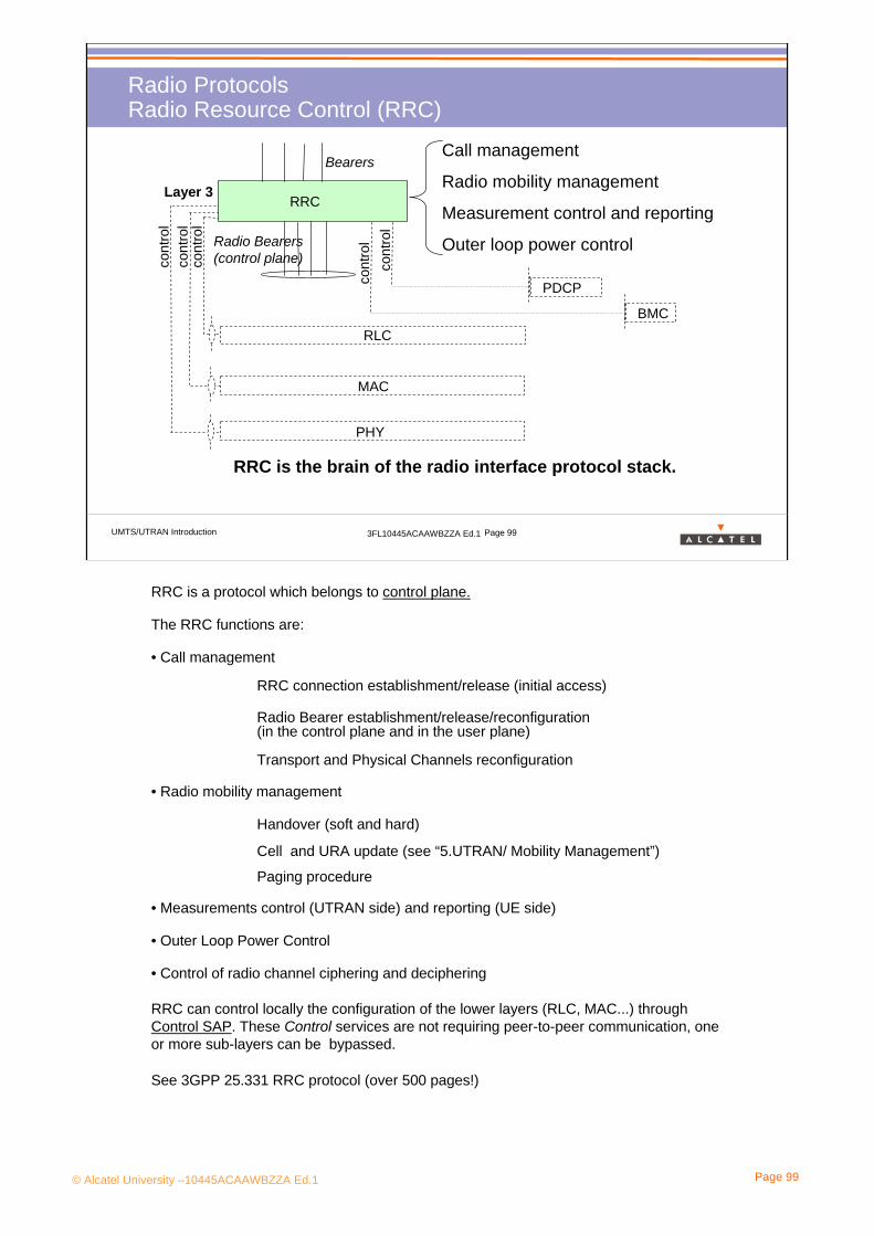
© Alcatel University –10445ACAAWBZZA Ed.1 Page 99
UMTS/UTRAN Introduction 3FL10445ACAAWBZZA Ed.1 Page 99
Radio ProtocolsRadio Resource Control (RRC)
cont
rol
cont
rol
cont
rol
PHY
MAC
RRC
RLC
BearersCall management
Radio mobility management
Measurement control and reporting
Outer loop power controlRadio Bearers(control plane)
RRC is the brain of the radio interface protocol stack.
Layer 3
cont
rol
cont
rol
PDCP
BMC
RRC is a protocol which belongs to control plane.
The RRC functions are:
• Call management
RRC connection establishment/release (initial access)
Radio Bearer establishment/release/reconfiguration (in the control plane and in the user plane)
Transport and Physical Channels reconfiguration
• Radio mobility management
Handover (soft and hard)
Cell and URA update (see “5.UTRAN/ Mobility Management”)
Paging procedure
• Measurements control (UTRAN side) and reporting (UE side)
• Outer Loop Power Control
• Control of radio channel ciphering and deciphering
RRC can control locally the configuration of the lower layers (RLC, MAC...) through Control SAP. These Control services are not requiring peer-to-peer communication, one or more sub-layers can be bypassed.
See 3GPP 25.331 RRC protocol (over 500 pages!)

© Alcatel University –10445ACAAWBZZA Ed.1 Page 100
UMTS/UTRAN Introduction 3FL10445ACAAWBZZA Ed.1 Page 100
Radio ProtocolsPDCP and BMC protocols
PDCP (Packet Data Convergence Protocol)
- in the user plane, only for services from the PS domain
- it contains compression methods
In R99 only a header compression method is mentioned (RFC2507).
Why is header compression valuable?
e.g a combined RTP/UDP/IP headers is at least 60 bytes for IPv6, when IP voice service header can be about 20 bytes or less.
BMC (Broadcast/Multicast Services)
- in the user plane
- to adapt broadcast and multicast services from NAS on the radio interface
In R99 the only service using this protocol is SMS Cell Broadcast Service (directly taken from GSM).
See 3 GPP 25.323 (PDCP protocol) and 25.324 (BMC protocol)

© Alcatel University –10445ACAAWBZZA Ed.1 Page 101
UMTS/UTRAN Introduction 3FL10445ACAAWBZZA Ed.1 Page 101
Radio ProtocolsRadio Link Control (RLC)
TrafficLogical
Channels
Radio Bearers(user plane)
Radio Bearers(control plane)
RLC RLCRLCRLC
RLCRLCRLCRLC
ControlLogical
Channels
Segmentation
Buffering
Data transfer with 3 configuration modes:
- Transparent (TM)
- Unacknowledged (UM)
- Acknowledged (AM)
Ciphering
RLC provides segmentation and (in AM mode) reliable data transfer.
Layer 2/upper part
There is no difference between RLC instances in Control and User planes. There is a single RLC connection per Radio Bearer.
RLC main functions:
• RLC Connection Establishment/Release in 3 configuration modes:- transparent data transfer (TM): without adding any protocol information - unacknowledged data transfer (UM): without guaranteeing delivery to the peer entity (but can detect transmission errors)- acknowledged data transfer (AM): with guaranteeing delivery to the peer entity. The AM mode provides reliable link (error detection and recovery, in-sequence delivery, duplicate detection, flow Control, ARQ mechanisms)
ARQ=Automatic Repeat Request (it manages retransmissions)• Transmission/Reception buffer• Segmentation and reassembly (to adjust the radio bearer size to the actual set of transport formats)• Mapping between Radio Bearers and Logical Channels (one to one)
•Ciphering for non-transparent RLC data (if not performed in MAC), using the UEA1, Kasumi algorithm specified in R’99
Encryption is performed in accordance with TS 33.102 (radio interface), 25.413, 25.331(RRC signaling messages) and supports the settings of integrity with CN (CS-domain/PS-domain)
3GPP 25.322 RLC protocol

© Alcatel University –10445ACAAWBZZA Ed.1 Page 102
UMTS/UTRAN Introduction 3FL10445ACAAWBZZA Ed.1 Page 102
Radio ProtocolsMedium Access Control (MAC)
Transport Channels
(common and dedicated)
Basic data transfer
Multiplexing of logical channels
Priority handling/Scheduling (TFC selection)
Reporting of measurements
Ciphering
MAC can switch a common channel into a dedicated channel if higher bit rate is required (on request of L3-level).
MAC can change dynamically Transport Format (bit rate…) of each transport channel on a frame basis (each 10 ms) without interchanging with L3-level.
MAC provides flexible data transfer.
TrafficLogical
Channels
ControlLogical
Channels
MACLayer 2/
lower part
MAC belongs to control plane and to user plane.
MAC main functions:
• Data transfer: MAC provides unacknowledged data transfer without segmentation
• Multiplexing of logical channels (possible only if they require the same QoS)
• Mapping between Logical Channels and Transport Channels
• Selection of appropriate Transport Format for each Transport Channel depending on instantaneous source rate.
• Priority handling/Scheduling according to priorities given by upper layers:- between data flows of one UE - between different UEs
Priority handling/Scheduling is done through Transport Format Combination (TFC) selection•Reporting of monitoring to RRC
•Ciphering for RLC transparent data (if not performed in RLC)
3GPP 25.321 MAC protocol

© Alcatel University –10445ACAAWBZZA Ed.1 Page 103
UMTS/UTRAN Introduction 3FL10445ACAAWBZZA Ed.1 Page 103
Radio ProtocolsThe Physical Layer
DedicatedPhysical Channels
Multiplexing of transport ch.
Spreading/modulation
RF processing
Power control
Measurements
Physical layer
DedicatedTransport Channels
The physical layer provides multiplexing and radio frequency processing with a CDMA method.
Air Interface
CommonTransport Channels
CommonPhysical Channels
Layer 1
The physical layer belongs to control plane and to user plane.
Physical layer main functions:
•Multiplexing/de-multiplexing of transport channels on CCTrCH (Coded Composite Transport Channel) even if the transport channels require different QoS.
•Mapping of CCTrCH on physical channels
•Spreading/de-spreading and modulation/demodulation of physical channels
•RF processing (3 GPP 25.10x)
•Frequency and time (chip, bit, slot, frame) synchronization
•Measurements and indication to higher layers (e.g. FER, SIR, interference power, transmit power, etc.)
•Open loop and Inner loop power control
•Macro-diversity distribution/combining and soft handover execution
3GPP 25.2xx

© Alcatel University –10445ACAAWBZZA Ed.1 Page 104
UMTS/UTRAN Introduction 3FL10445ACAAWBZZA Ed.1 Page 104
CCCHPCCH BCCH CTCH DTCHDCCH DTCH
Radio ProtocolsExercise: MAC protocol (1)
BCCH
FACH RACH DSCH
Iur or local
DCH DCH
MAC-d
MAC-c/sh
CPCHFACHPCH
MAC Control
DSCH
Look at this figure and answer the questions on the following paLook at this figure and answer the questions on the following pages.ges.
MAC-b
BCH
© Alcatel University –10445ACAAWBZZA Ed.1 Page 105
UMTS/UTRAN Introduction 3FL10445ACAAWBZZA Ed.1 Page 105
Radio ProtocolsExercise: MAC protocol (2)
1. On which logical/transport channels will be mapped:- system information broadcasting- paging- telephony speech- internet browsing at a high bit rate- internet browsing at a low bit rateCan you imagine a situation where the UE will use 2 DTCHs (or more) at the same time?
2. Guess the meaning of “MAC-b” “MAC-c/sh” and “MAC-d”.
3. Why is there one MAC-d entity on the UE side and several MAC-d entities on the UTRAN side?
4. What is the link between MAC-c/sh and MAC-d for?
5. What are the 4 main functions of MAC protocol?
6. MAC can multiplex logical channels only if they require the same QoS: true or false?

© Alcatel University –10445ACAAWBZZA Ed.1 Page 106
UMTS/UTRAN Introduction 3FL10445ACAAWBZZA Ed.1 Page 106
Radio ProtocolsExercise: MAC protocol (3)
7. RNTI (Radio Network Temporary Identity) is an UE identity assigned by UTRAN, when the UE is connected to the UTRAN . The parameter RNTI is included in the header of each transport blocks in MAC-c/sh, but not in MAC-d : can you explain the reason?
8. The system can also multiplex transport channels: where does that take place?
9. What is the name of the channel on which several time-coordinated transport channels can be multiplexed?
10. Which entity is responsible for TFC selection? TFCS allocation?
11. Is it possible to multiplex 2 FACHs (or more)? 2 DCHs (or more)? a FACH and a DCH?
12. Will the physical channel configuration be changed (e.g modification of spreading factor) when MAC selects a new TFC inside TFCS?
13. MAC makes measurement reports to RRC: why is it necessary?

© Alcatel University –10445ACAAWBZZA Ed.1 Page 107
4. WCDMA in UMTS

© Alcatel University –10445ACAAWBZZA Ed.1 Page 108
UMTS/UTRAN Introduction 3FL10445ACAAWBZZA Ed.1 Page 108
4. WCDMA for UMTSSection presentation> Objective: to be able to define a Radio Resource in 3G.
> Program: • 4.1 Context• 4.2 Analogy • 4.3 Spread Spectrum Modulation• 4.4 Code Division Multiple Access• 4.5 Soft HandOver • 4.6 Rake Receiver• 4.7 Power Control• 4.8 Capacity, Coverage & Quality

© Alcatel University –10445ACAAWBZZA Ed.1 Page 109
4. WCDMA in UMTS
4.1 Context
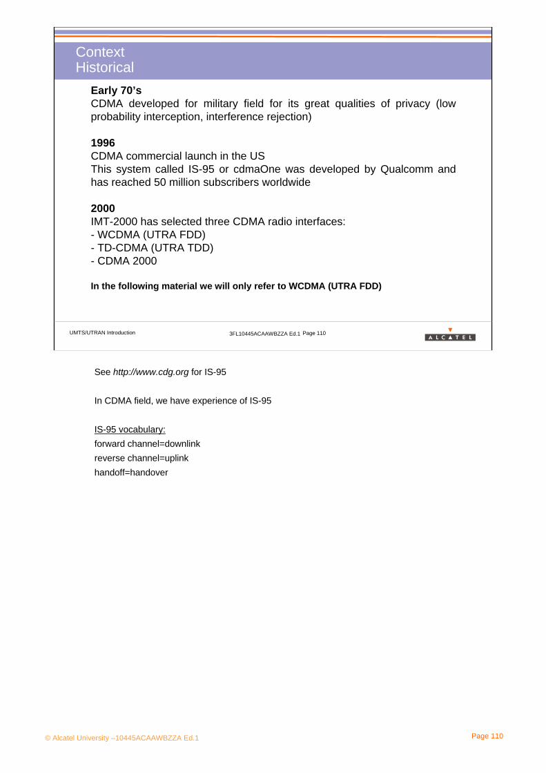
© Alcatel University –10445ACAAWBZZA Ed.1 Page 110
UMTS/UTRAN Introduction 3FL10445ACAAWBZZA Ed.1 Page 110
ContextHistorical
Early 70’sCDMA developed for military field for its great qualities of privacy (low probability interception, interference rejection)
1996CDMA commercial launch in the USThis system called IS-95 or cdmaOne was developed by Qualcomm and has reached 50 million subscribers worldwide
2000IMT-2000 has selected three CDMA radio interfaces:- WCDMA (UTRA FDD)- TD-CDMA (UTRA TDD)- CDMA 2000
In the following material we will only refer to WCDMA (UTRA FDD)
See http://www.cdg.org for IS-95
In CDMA field, we have experience of IS-95
IS-95 vocabulary:forward channel=downlinkreverse channel=uplink handoff=handover

© Alcatel University –10445ACAAWBZZA Ed.1 Page 111
UMTS/UTRAN Introduction 3FL10445ACAAWBZZA Ed.1 Page 111
ContextAdvantages & Disadvantages
CDMA is very attractive:
• Better spectrum efficiency than 2G systems
• Suitable for all type of services (circuit, packet) and for multi-services
• Enhanced privacy
• Evolutionary (linked with progress in signal processing field)
BUT:
• Complex system: not easy to configure and to manage
• Unstable in case of congestion
Spectrum efficiency : transmission capacity per spectrum unit (bandwidth), i.e kbit/MHz. This must not be confused with the traffic capacity.The spectrum efficiency in UMTS is higher than in GSM (25x200kHz carriers in GSM offering 335 kbps** while a 5 MHz UMTS carrier offers 400 kbps).If we factor in densification (frequency reuse pattern), the UMTS traffic capacity isdramatically increased. According to CDMA Development Group:“Capacity increases by a factor of between 8 to 10 compared to an AMPSanalog system and between 4 to 5 times compared to a GSM system”
© Alcatel University –10445ACAAWBZZA Ed.1 Page 112
4. WCDMA in UMTS
4.2 Analogy

© Alcatel University –10445ACAAWBZZA Ed.1 Page 113
UMTS/UTRAN Introduction 3FL10445ACAAWBZZA Ed.1 Page 113
• Cell
Restaurant room
AnalogyWCDMA and Restaurant
WCDMA Restaurant Room
• UE
People at table
• Code
Language
Enjoy your meal !
Code 1
Code 2
Guten appetite !
Bon appetit !
Bomapetite !
Ues, like people, send and receive on the same time and the same frequency. They are separeted by:
For a table, the conversations of the neighbours are noise, for a UE it is the same principle: neighbour conversations are interference
The equivalence are:
Restaurant room -> Cell
Table -> UE
Language -> Code
Here the important point is all the UEs send and receive on the same time and on the same frequency. The WCDMA is really different because with the GSM, the UEs are separated by the time (TS of TDMA) and the frequency. Here the UEs are separated with codes applied on the signals.
Another important point is for someone the conversation on a neighbour table is considered like noise. It is the same principle with the WCDMA, for a user the other UEs generates some noises.
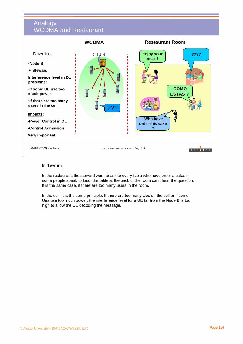
© Alcatel University –10445ACAAWBZZA Ed.1 Page 114
UMTS/UTRAN Introduction 3FL10445ACAAWBZZA Ed.1 Page 114
AnalogyWCDMA and Restaurant
WCDMA Restaurant Room
•Node B
Steward
Downlink Enjoy your meal !
Who have order this cake
?
COMO ESTAS ?
????
???
Interference level in DL probleme:
•If some UE use too much power
•If there are too many users in the cell
Impacts:
•Power Control in DL
•Control Admission
Very important !
In downlink,
In the restaurant, the steward want to ask to every table who have order a cake. If some people speak to loud, the table at the back of the room can’t hear the question. It is the same case, if there are too many users in the room.
In the cell, it is the same principle. If there are too many Ues on the cell or if some Ues use too much power, the interference level for a UE far from the Node B is too high to allow the UE decoding the message.

© Alcatel University –10445ACAAWBZZA Ed.1 Page 115
UMTS/UTRAN Introduction 3FL10445ACAAWBZZA Ed.1 Page 115
AnalogyWCDMA & Restaurant
WCDMA Restaurant Room
It is for me !
Who have order this cake
?
QUIERO LA TARTA !
Es ist meineUplink
C’est à la pomme ?
????
At the Node B level:
• If a UE, close to the NB, speak too loud
•If there are too many users
Probleme of interfence level problem.
The NB can’t decode any users.Impacts:
• Power Control in UL
•Admission Control
Very important
In Uplink, In the restaurant, a steward can understand all the conversation if he knows all the languages.But if on a table, close to him, some one speak to loud the steward can’t understand people on the other tables. It is the same problem if there are too many people it is too noisy to ableable to understand a conversation far from him.With the WCDMA, there is the same problem. That means if the cell is too load, the interference level at the Node B is too high to be able to decode the weakest signal.

© Alcatel University –10445ACAAWBZZA Ed.1 Page 116
4. WCDMA in UMTS
4.3 Spread Spectrum Modulation

© Alcatel University –10445ACAAWBZZA Ed.1 Page 117
UMTS/UTRAN Introduction 3FL10445ACAAWBZZA Ed.1 Page 117
Spread Spectrum ModulationA Code as a Shell against Noise
The letter ‘A’ represents the signal to transmit over the radio interface.
At the transmitter the height (ie the power) of ‘A’ is spread, while a color (i.e a code) is added to ‘A’ to identify the message .
At the receiver ‘A’ can be retrieved with knowledge of the code, even if the power of the received signal is below the power of noise due to the radio channel.
ReceiverTransmitter
Spreading
Noise
DespreadingRadio Channel
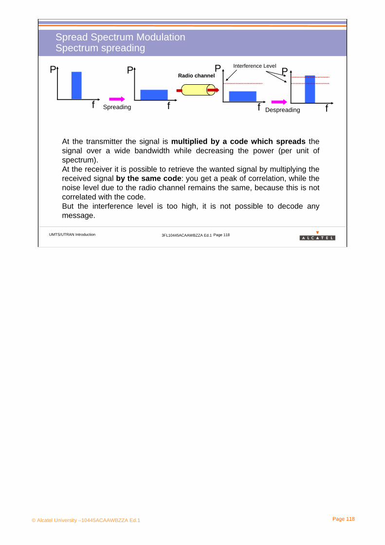
© Alcatel University –10445ACAAWBZZA Ed.1 Page 118
UMTS/UTRAN Introduction 3FL10445ACAAWBZZA Ed.1 Page 118
Spread Spectrum ModulationSpectrum spreading
At the transmitter the signal is multiplied by a code which spreads the signal over a wide bandwidth while decreasing the power (per unit of spectrum).At the receiver it is possible to retrieve the wanted signal by multiplying the received signal by the same code: you get a peak of correlation, while the noise level due to the radio channel remains the same, because this is not correlated with the code.But the interference level is too high, it is not possible to decode any message.
f
P
f
P
Spreading
Radio channel
f f
P P
Despreading
Interference Level

© Alcatel University –10445ACAAWBZZA Ed.1 Page 119
UMTS/UTRAN Introduction 3FL10445ACAAWBZZA Ed.1 Page 119
Spread Spectrum ModulationTransmission Chain
Air Interface
The narrowband data signal is multiplied bit per bit by a code sequence: it is known as “chipping”.
The chip rate of this code sequence is much higher than the bit rate of the data signal: it produces a wideband signal, also called spread signal.
At the receiver the same code sequence in phase should be used to retrieve the original data signal.
Modulator Demodulator
Code Sequence
Data Data
Code sequence
NB-Signal WB-Signal NB-SignalWB-Signal
Code synchronization between the transmitter and the receiver is crucial for de-spreading the wideband signal successfully.
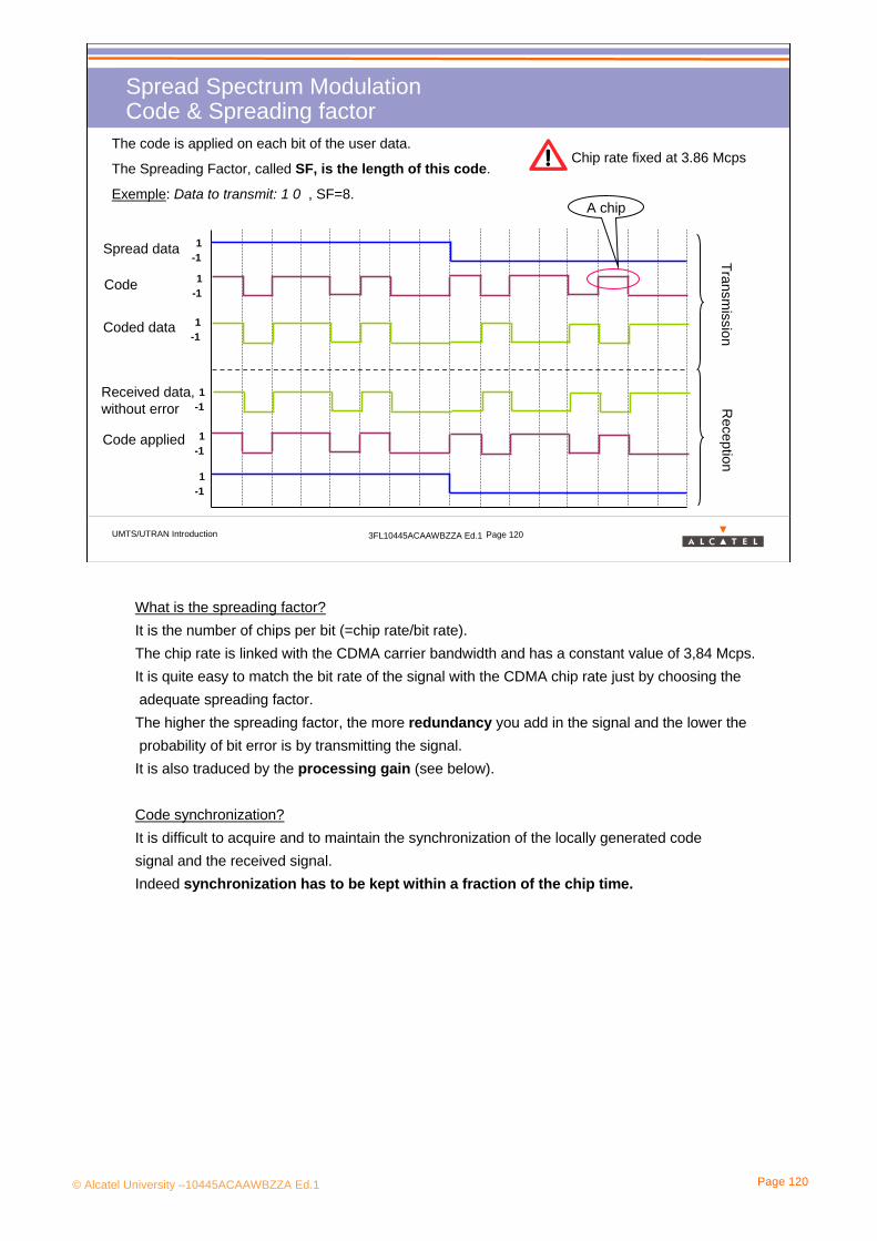
© Alcatel University –10445ACAAWBZZA Ed.1 Page 120
UMTS/UTRAN Introduction 3FL10445ACAAWBZZA Ed.1 Page 120
Spread Spectrum ModulationCode & Spreading factor
The code is applied on each bit of the user data.
The Spreading Factor, called SF, is the length of this code.
Exemple: Data to transmit: 1 0 , SF=8.
1-1
1-1
Spread data
Code
Coded data
Transmission
Reception
Received data, without error
1-1
A chip
Chip rate fixed at 3.86 Mcps
Code applied
1-1
1-1
1-1
What is the spreading factor?It is the number of chips per bit (=chip rate/bit rate).The chip rate is linked with the CDMA carrier bandwidth and has a constant value of 3,84 Mcps. It is quite easy to match the bit rate of the signal with the CDMA chip rate just by choosing theadequate spreading factor.The higher the spreading factor, the more redundancy you add in the signal and the lower theprobability of bit error is by transmitting the signal.It is also traduced by the processing gain (see below).
Code synchronization?It is difficult to acquire and to maintain the synchronization of the locally generated code signal and the received signal. Indeed synchronization has to be kept within a fraction of the chip time.
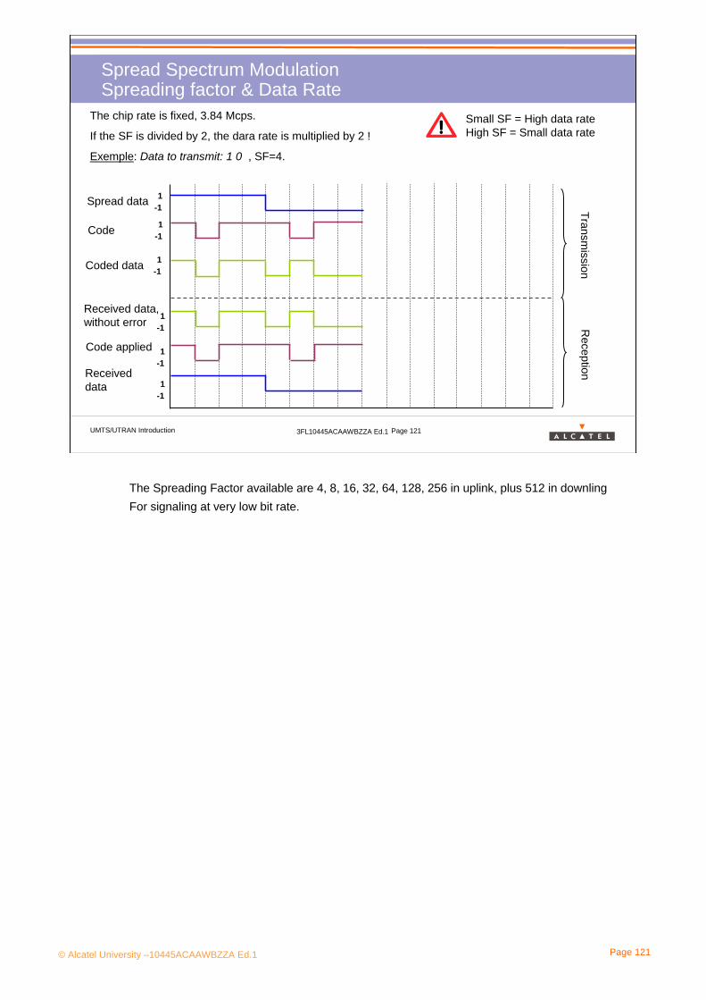
© Alcatel University –10445ACAAWBZZA Ed.1 Page 121
UMTS/UTRAN Introduction 3FL10445ACAAWBZZA Ed.1 Page 121
Spread Spectrum ModulationSpreading factor & Data Rate
The chip rate is fixed, 3.84 Mcps.
If the SF is divided by 2, the dara rate is multiplied by 2 !
Exemple: Data to transmit: 1 0 , SF=4.
Spread data
Code
Coded data
Transmission
Reception
Received data, without error
Code applied
Received data
Small SF = High data rate High SF = Small data rate
1-1
1-1
1-1
1-1
1-1
1-1
The Spreading Factor available are 4, 8, 16, 32, 64, 128, 256 in uplink, plus 512 in downling For signaling at very low bit rate.

© Alcatel University –10445ACAAWBZZA Ed.1 Page 122
UMTS/UTRAN Introduction 3FL10445ACAAWBZZA Ed.1 Page 122
Spread Spectrum ModulationSpreading factor & Error at reception (1/2)
When an error occurs at the reception, the determination of the bit value is less trivial.
Exemple: Data to transmit: 1 0 , SF=8.
1-1
1-1
Signal sent on the air Signal received with error
Code
SF=8
Zoom on the decoded
signal
Decoded data
1
-1
0
The determination of the bit value is based on the aera of the received signal.
Here is 3 area unity over 4
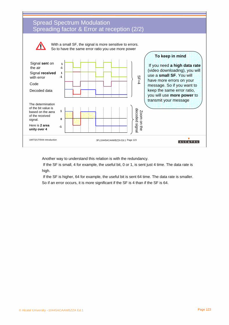
© Alcatel University –10445ACAAWBZZA Ed.1 Page 123
UMTS/UTRAN Introduction 3FL10445ACAAWBZZA Ed.1 Page 123
Spread Spectrum ModulationSpreading factor & Error at reception (2/2)
1-1
1-1
Signal sent on the air Signal received with error
Code
SF=4
Zoom on the
decoded signalDecoded data
1
-1
0
The determination of the bit value is based on the aera of the received signal.
Here is 2 area unity over 4
With a small SF, the signal is more sensitive to errors. So to have the same error ratio you use more power
If you need a high data rate(video downloading), you will use a small SF. You will have more errors on your message. So if you want to keep the same error ratio, you will use more power to transmit your message
To keep in mind
Another way to understand this relation is with the redundancy.If the SF is small, 4 for example, the useful bit, 0 or 1, is sent just 4 time. The data rate is high.If the SF is higher, 64 for example, the useful bit is sent 64 time. The data rate is smaller.So if an error occurs, it is more significant if the SF is 4 than if the SF is 64.
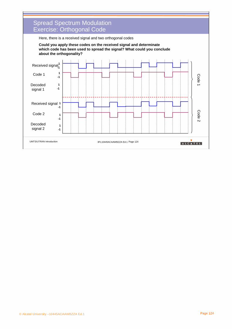
© Alcatel University –10445ACAAWBZZA Ed.1 Page 124
UMTS/UTRAN Introduction 3FL10445ACAAWBZZA Ed.1 Page 124
Spread Spectrum ModulationExercise: Orthogonal Code
Here, there is a received signal and two orthogonal codes
Could you apply these codes on the received signal and determinate which code has been used to spread the signal? What could you conclude about the orthogonality?
Received signal
Code 1
Decoded signal 1
Code 1
Code 2
Code 2
1-1
1-1
1-1
1-1
1-1
1-1
Received signal
Decoded signal 2

© Alcatel University –10445ACAAWBZZA Ed.1 Page 125
UMTS/UTRAN Introduction 3FL10445ACAAWBZZA Ed.1 Page 125
Spread Spectrum ModulationWCDMA, Power Density & Processing Gain (1/2)
f
P
RSSI or Io
ISCP or No
SIR
PG
Eb
RSCP or Ec
At Node B reception level
•RSSI: Received Signal Strength Indicator
Total received wideband power over 5 Mhz including thermal noise•ISCP (No): Interference Signal Code Power
Interference on the received signal
•RSCP (Ec): Received Signal Code Power
Unbiaised measurement on the received signal on one channelization code• Eb : energy per useful bit
• PG : Processing Gain = Eb-Ec
Power Gain after despreading. PG= 20 log (Wss/Ws)
WssWs
RSSI: This is the total received wideband (UTRA carrier RSSI) power over 5Mhzincluding thermal noise. It is estimating the uplink interference at the Node B, and by difference with the thermal noise, the rise due to traffic and external interference.
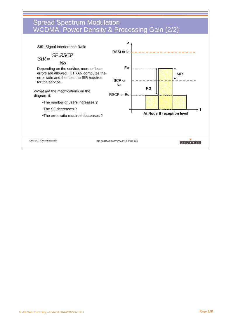
© Alcatel University –10445ACAAWBZZA Ed.1 Page 126
UMTS/UTRAN Introduction 3FL10445ACAAWBZZA Ed.1 Page 126
Spread Spectrum ModulationWCDMA, Power Density & Processing Gain (2/2)
f
P
RSSI or Io
ISCP or No
SIR
PG
Eb
RSCP or Ec
At Node B reception level
SIR: Signal Interference Ratio
NoRSCPSFSIR .
=
•What are the modifications on the diagram if:
•The number of users increases ?
•The SF decreases ?
•The error ratio required decreases ?
Depending on the service, more or less errors are allowed. UTRAN computes theerror ratio and then set the SIR requiredfor the service.

© Alcatel University –10445ACAAWBZZA Ed.1 Page 127
4. WCDMA in UMTS
4.4 Code Division Multiple Access

© Alcatel University –10445ACAAWBZZA Ed.1 Page 128
UMTS/UTRAN Introduction 3FL10445ACAAWBZZA Ed.1 Page 128
Code Division Multiple AccessOne-cell reuse
The area is divided into cells, but the entire bandwidth is reused in each cell (frequency reuse of one)
> Inter-cell interference
> Cell orthogonality is achieved by codes
The entire bandwidth is used by each user at the same time
> Intra-cell interference
> User orthogonality is achieved by codes
The rainbows cells mean that the whole bandwidth (5 MHz) is reused in each cell.
In GSM there is also intra-cell interference when there are 2 (or more) TRXs in the same cell. But it is a small problem (as each TRX runs on a different frequency) In CDMA intra-cell interference is an important problem.

© Alcatel University –10445ACAAWBZZA Ed.1 Page 129
UMTS/UTRAN Introduction 3FL10445ACAAWBZZA Ed.1 Page 129
Code Division Multiple AccessMultiple access (1)
All the users transmit on the same 5 MHz carrier at the same time and interfere with each over.
At the receiver the users can be separated by means of (quasi-)orthogonal codes.
Transmitter 2
Spreading 1
Spreading1
Spreading 2 Receiver
Radio ChannelTransmitter 1
The receiver aims at receiving Transmitter 1 only.
Quasi-orthogonal: it is not necessary to have primary colors at the receiver to separate the user. Red and orange for example can also be distinguished.Orthogonality between the codes is impossible to maintain after transfer over the radio interface (multi-path on DL, UEs not synchronized on UL )
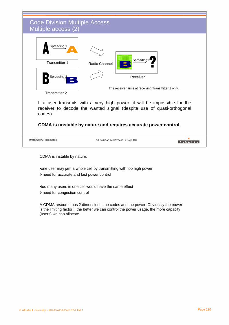
© Alcatel University –10445ACAAWBZZA Ed.1 Page 130
UMTS/UTRAN Introduction 3FL10445ACAAWBZZA Ed.1 Page 130
Code Division Multiple AccessMultiple access (2)
If a user transmits with a very high power, it will be impossible for the receiver to decode the wanted signal (despite use of quasi-orthogonal codes)
CDMA is unstable by nature and requires accurate power control.
Transmitter 2
Receiver
Radio ChannelTransmitter 1
The receiver aims at receiving Transmitter 1 only.
Spreading 1
Spreading1
Spreading 2
CDMA is instable by nature:
•one user may jam a whole cell by transmitting with too high powerneed for accurate and fast power control
•too many users in one cell would have the same effectneed for congestion control
A CDMA resource has 2 dimensions: the codes and the power. Obviously the power is the limiting factor ; the better we can control the power usage, the more capacity (users) we can allocate.

© Alcatel University –10445ACAAWBZZA Ed.1 Page 131
UMTS/UTRAN Introduction 3FL10445ACAAWBZZA Ed.1 Page 131
Code Division Multiple AccessSpreading: Channelization and Scrambling
2chc
3chc
1chc
scramblingc
The channelization code (or spreading code) is signal-specific: the code length is chosen according to the bit rate of the signal.
The scrambling code is equipment-specific.
air interface
Modulator
Spreading consists of two steps:• The channelization code (also called spreading code) transforms every data symbol into a number of chips, thus increasing the bandwidth of the signal. The narrowband signal is spread into a wideband signal with a chip rate of 3.84 Mchips/s. The system must choose the adequate spreading factor to match the bit rate of the narrowband signal.The spreading factor is directly linked with the length of the channelization code.
• The scrambling code does not affect the signal bandwidth: it is only a chip-by-chip operation.The scrambling code is cell-specific on the downlink and terminal-specific on the uplink.
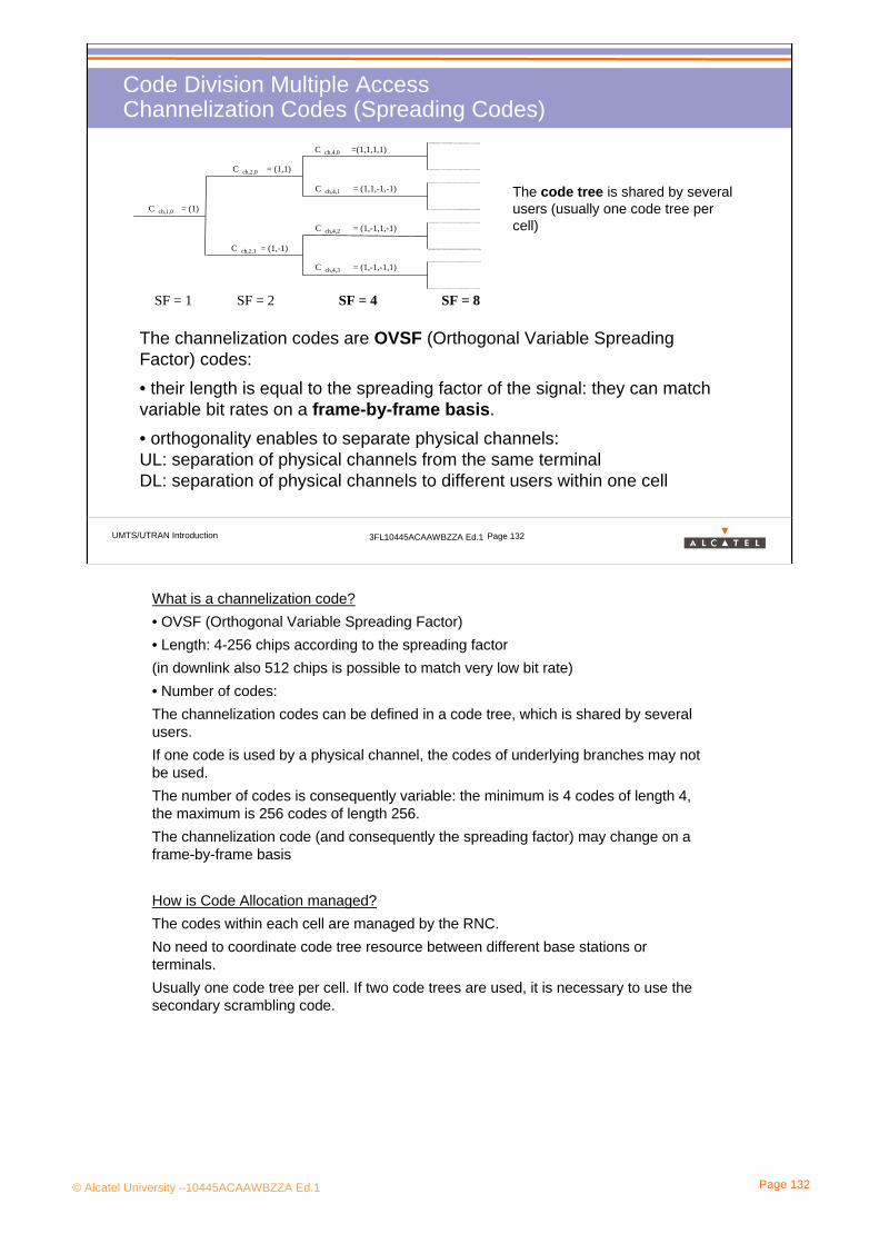
© Alcatel University –10445ACAAWBZZA Ed.1 Page 132
UMTS/UTRAN Introduction 3FL10445ACAAWBZZA Ed.1 Page 132
Code Division Multiple AccessChannelization Codes (Spreading Codes)
The channelization codes are OVSF (Orthogonal Variable Spreading Factor) codes: • their length is equal to the spreading factor of the signal: they can match variable bit rates on a frame-by-frame basis.• orthogonality enables to separate physical channels:UL: separation of physical channels from the same terminalDL: separation of physical channels to different users within one cell
SF = 1
C ch,1,0 = (1)
C ch,2,0 = (1,1)
C ch,2,1 = (1,-1)
C ch,4,0 =(1,1,1,1)
C ch,4,1 = (1,1,-1,-1)
C ch,4,2 = (1,-1,1,-1)
C ch,4,3 = (1,-1,-1,1)
SF = 4SF = 2 SF = 8
The code tree is shared by several users (usually one code tree per cell)
What is a channelization code?• OVSF (Orthogonal Variable Spreading Factor)• Length: 4-256 chips according to the spreading factor(in downlink also 512 chips is possible to match very low bit rate) • Number of codes:The channelization codes can be defined in a code tree, which is shared by several users.If one code is used by a physical channel, the codes of underlying branches may not be used.The number of codes is consequently variable: the minimum is 4 codes of length 4, the maximum is 256 codes of length 256. The channelization code (and consequently the spreading factor) may change on a frame-by-frame basis
How is Code Allocation managed?The codes within each cell are managed by the RNC.No need to coordinate code tree resource between different base stations or terminals.Usually one code tree per cell. If two code trees are used, it is necessary to use the secondary scrambling code.

© Alcatel University –10445ACAAWBZZA Ed.1 Page 133
UMTS/UTRAN Introduction 3FL10445ACAAWBZZA Ed.1 Page 133
Code Division Multiple AccessScrambling codes
The scrambling codes provide separation between equipment:• UL: separation of terminalsNo need for code planning (millions of codes!)There are 214 long and 214 short scrambling codes in uplink
• DL: separation of cellsNeed for code planning between cells (but trivial task)There are only long scrambling codes in downlink(512 to limit the code identification during cell search procedure)
The long scrambling codes are truncated to the 10 ms frame length.
Only one DL scrambling code should be used within a cell.Another scrambling code may be introduced in one cell if necessary (example : shortage of channelization code), but orthogonality between users will be degraded.
In fact, there are two types of scrambling codes:• Long codes:
•Gold codes constructed from a position wise modulo 2 sum of 38400 chip segments of two binary sequences (generated by means of 2 generators polynomials of degree 25)•used with Rake Receiver : the PRACH is constructed from the longscrambling sequences. There are 8192 PRACH preamble scrambling codes in total, divided into 512 groups of 16 each.
• Short codes: •Length : 256 chips•used with advanced multi-user detector•likely to be used later
Refer to Technical Specification 3GPP TS 25.213

© Alcatel University –10445ACAAWBZZA Ed.1 Page 134
4. WCDMA in UMTS
4.5 Soft Handover

© Alcatel University –10445ACAAWBZZA Ed.1 Page 135
UMTS/UTRAN Introduction 3FL10445ACAAWBZZA Ed.1 Page 135
Soft HandoverIntroduction
Principle: As the UEs are separated by codes, they send and receive data all on the same time and on the same frequency and one frequency is used in a set of adjacent cells, the soft handover is possible.
A UE is in case of Soft Handover when it is linked to several cells on the same time.
So , in donwlink, the UE receives several time the same data and combine them toincrease the quality. In Uplink, several cells and Node can receive the same message and combines them to increase the quality.
Soft Handover doesn’t exist in GSM, it is not possible because there are different frequencies in a set of adjacent cells.
Interest: Like the quality of the signal is increased after the reception, it is possible to use less power. That allows to save the interference level. If this interference level is too high, it is not possible to decode the data and the call is cut.

© Alcatel University –10445ACAAWBZZA Ed.1 Page 136
UMTS/UTRAN Introduction 3FL10445ACAAWBZZA Ed.1 Page 136
Soft HandoverScenarios: Softer Handover
Iu
Core Network
Iubs Iubs
Iur
Iu
Serving RNC
Serving RNC (SRNC1): on UL it collects information from the Drift RNC and from its ownNode-B and performs selection of the signal on a best frame quality basis. On DL it duplicates Iu-information to Drift RNC and to its own Node-B and recombination of the signal is performed by the UE. There may be only one Serving RNC per UE.
Drift RNC (DRNC2): it performs the routing of information from/to the Serving RNC.There may be up to 4 Drift RNC(s) per UE.

© Alcatel University –10445ACAAWBZZA Ed.1 Page 137
UMTS/UTRAN Introduction 3FL10445ACAAWBZZA Ed.1 Page 137
Soft HandoverScenarios: Soft Handover
Iu
Core Network
Iubs Iubs
Iur
Iu
Serving RNC
Serving RNC (SRNC1): on UL it collects information from the Drift RNC and from itsown Node-B and performs selection of the signal on a best frame quality basis.On DL it duplicates Iu-information to Drift RNC and to its own Node-B and recombinationof the signal is performed by the UE. There may be only one Serving RNC per UE.
Drift RNC (DRNC2): it performs the routing of information from/to the Serving RNC.There may be up to 4 Drift RNC(s) per UE.

© Alcatel University –10445ACAAWBZZA Ed.1 Page 138
UMTS/UTRAN Introduction 3FL10445ACAAWBZZA Ed.1 Page 138
Soft HandoverScenarios: Soft Handover inter RNC
Iu
Core Network
Iubs Iubs
Iur
Iu
Serving RNC Drift RNCIur
Serving RNC (SRNC1): on UL it collects information from the Drift RNC and from itsown Node-B and performs selection of the signal on a best frame quality basis. On DL it duplicates Iu-information to Drift RNC and to its own Node-B and recombination of the signal is performed by the UE. There may be only one Serving RNC per UE.
Drift RNC (DRNC2): it performs the routing of information from/to the Serving RNC.There may be up to 4 Drift RNC(s) per UE.
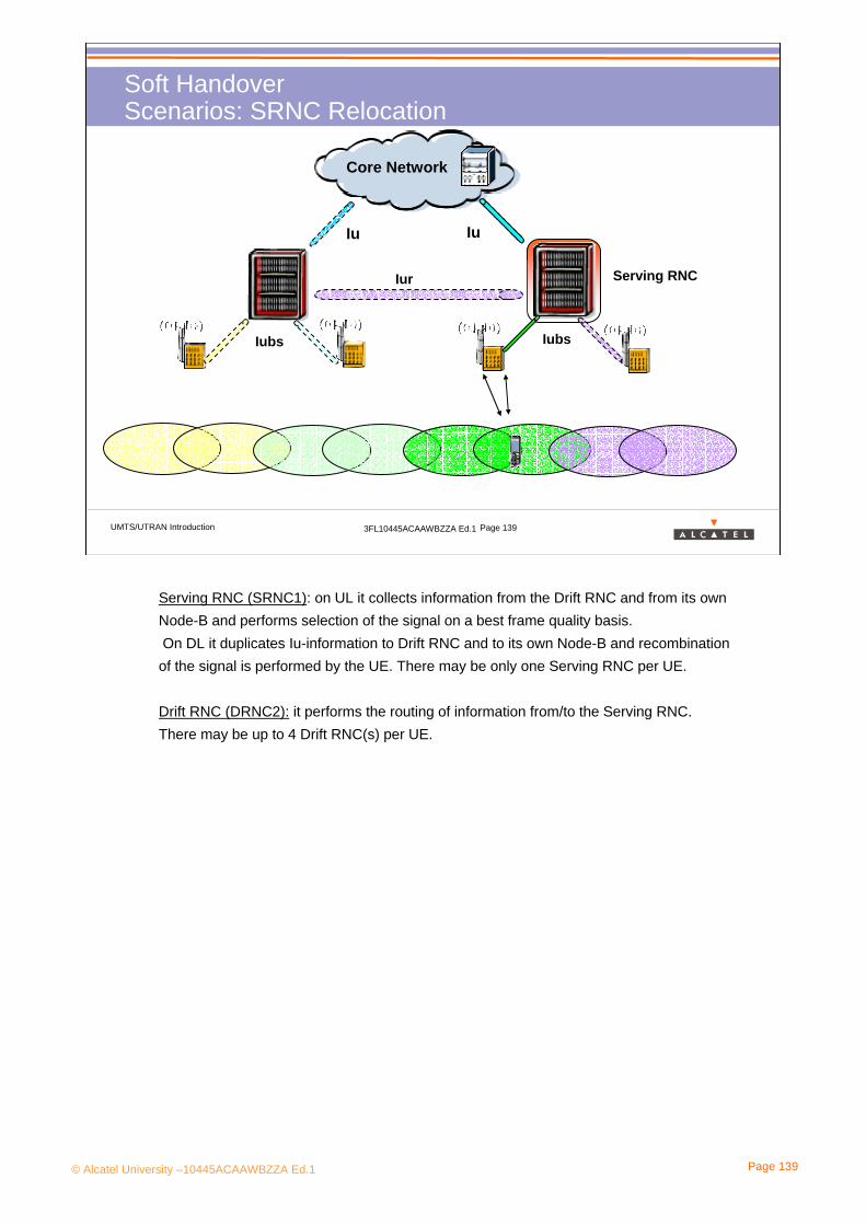
© Alcatel University –10445ACAAWBZZA Ed.1 Page 139
UMTS/UTRAN Introduction 3FL10445ACAAWBZZA Ed.1 Page 139
IurIur
Soft HandoverScenarios: SRNC Relocation
Iu
Core Network
Iubs Iubs
Iu
Serving RNC Drift RNC
Iu
Serving RNC
Serving RNC (SRNC1): on UL it collects information from the Drift RNC and from its own Node-B and performs selection of the signal on a best frame quality basis.On DL it duplicates Iu-information to Drift RNC and to its own Node-B and recombination of the signal is performed by the UE. There may be only one Serving RNC per UE.
Drift RNC (DRNC2): it performs the routing of information from/to the Serving RNC.There may be up to 4 Drift RNC(s) per UE.
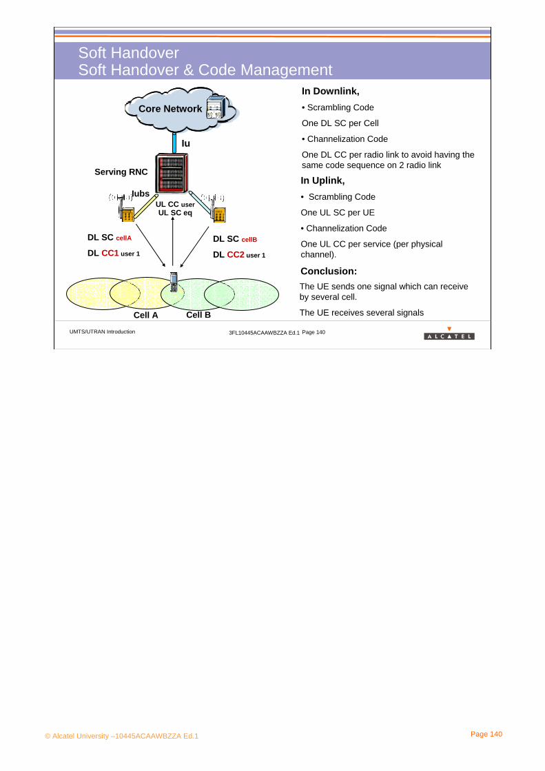
© Alcatel University –10445ACAAWBZZA Ed.1 Page 140
UMTS/UTRAN Introduction 3FL10445ACAAWBZZA Ed.1 Page 140
Soft HandoverSoft Handover & Code Management
Iu
Core Network
Iubs
Serving RNC
In Downlink, • Scrambling Code
One DL SC per Cell
• Channelization Code
One DL CC per radio link to avoid having the same code sequence on 2 radio link
In Uplink, • Scrambling Code
One UL SC per UE
• Channelization Code
One UL CC per service (per physical channel).
Cell A Cell B
DL SC cellA
DL CC1 user 1
DL SC cellB
DL CC2 user 1
UL SC eqUL CC user
The UE sends one signal which can receive by several cell.
The UE receives several signals
Conclusion:
© Alcatel University –10445ACAAWBZZA Ed.1 Page 141
UMTS/UTRAN Introduction 3FL10445ACAAWBZZA Ed.1 Page 141
Soft HandoverCost & Benefit
Why do we need soft HO?Imagine that a UE penetrates from one cell deeply into an adjacent cell:
it may cause near-far effecthard HO is not a good solution, due to the hysteresis mechanism
Better spatial repartition of the power, so lower interference level
Additional resources due to soft HO:- Additional rake receiver in Node-B- Additional Rake Fingers in UE- Additional transmission links between Node-Bs and RNCs
Soft HO provides Diversity (also called Macro-Diversity), but requires more network resource.
© Alcatel University –10445ACAAWBZZA Ed.1 Page 142
UMTS/UTRAN Introduction 3FL10445ACAAWBZZA Ed.1 Page 142
> Soft Handover execution:• Soft Handover is executed by means of the following procedures
– Radio Link Addition (FDD soft-add);– Radio Link Removal (FDD soft-drop);– Combined Radio Link Addition and Removal.
• The cell to be added to the active set needs to have informationforwarded by the RNC:
– Connection parameters (coding scheme, layer 2 information, …)– UE ID and uplink scrambling code,– Timing information from UE
• The UE needs to get the following information– Channelization & scrambling codes to be used– Relative timing information (Timing offset based on CPICH
synchro)
Soft HandoverCost & Benefit

© Alcatel University –10445ACAAWBZZA Ed.1 Page 143
4. WCDMA in UMTS
4.6 Rake Receiver
© Alcatel University –10445ACAAWBZZA Ed.1 Page 144
UMTS/UTRAN Introduction 3FL10445ACAAWBZZA Ed.1 Page 144
Rake ReceiverRake Receiver principle (1)
In a CDMA system there is a single carrier which contains all user signals.
Decoding of all these signals by one receiver is only a question of signal processing capacity.
A Rake receiver is capable to decode several signals simultaneously in the so called “fingers” and to combine them in order to improve the quality of the signal or to get several services at the same time.
A Rake receiver is implemented in mobile phones and in base stations.
A Rake receiver can provide:- multi-service (via handling of multiple physical channels that are carrying the services)- soft handover - path diversity
“A single carrier”: in fact each operator may use several carriers of 5MHz each (2 in Germany, 3 in France) The rake receiver can only be used with signals on the same carrier.

© Alcatel University –10445ACAAWBZZA Ed.1 Page 145
UMTS/UTRAN Introduction 3FL10445ACAAWBZZA Ed.1 Page 145
Rake ReceiverRake receiver principle (2)
The components of the multi-code signal are demodulated in parallel each in one “finger” of the Rake Receiver.
The outputs of the fingers:• can provide independent data signals• can be combined to provide a better data signal(s)
Delay 1Code Sequence 1
Code Sequence 2 or 3
Code Sequence 2Delay 2
Delay 3
Data 2
1stFinger
2ndFinger
3rdFinger
Data 1
Multi-code signal
Delay Adjustment
Rake fingers are allocated to the peaks at which significant energy arrives. Update rate: tens of ms
Each finger tracks the fast-changing phase and amplitude values due to fast fading and removes them
Rake Receiver resides in both UE and Node-B.
The numbers of fingers for a Rake Receiver is implementation dependant.

© Alcatel University –10445ACAAWBZZA Ed.1 Page 146
UMTS/UTRAN Introduction 3FL10445ACAAWBZZA Ed.1 Page 146
Rake ReceiverRake Receiver and Multi-Service
As a first approach, we can say:
One service, one code! (*)
Multimedia receiverTransmitter
Spreading 1 Despreading 1
Radio ChannelSpreading 2
Despreading 2
>> Which codes make it possible to >> Which codes make it possible to separate the two signals at the receiver?separate the two signals at the receiver?
* we will see later that it is also possible to multiplex several services on the same code! Indeed on a dedicated physical channel (which is identified by its spreading code) a user can multiplex several services as long as the total bit rate of the services does not exceed the bit rate of the physical channel.See subchapter 5.UTRAN/ Physical Layer (Transport Channel Multiplexing)

© Alcatel University –10445ACAAWBZZA Ed.1 Page 147
UMTS/UTRAN Introduction 3FL10445ACAAWBZZA Ed.1 Page 147
Rake ReceiverRake Receiver and soft handover
Soft handover is possible, because the two mobile stations use the same frequency band. The mobile phone need only one transmission chain to decode both simultaneously.
Base Station 2
Spreading 1
Despreading 1&2
Spreading 2 Mobile phone
Radio ChannelBase station 1
>> Which codes make it possible to >> Which codes make it possible to separate the two signals at the separate the two signals at the receiver?receiver?

© Alcatel University –10445ACAAWBZZA Ed.1 Page 148
UMTS/UTRAN Introduction 3FL10445ACAAWBZZA Ed.1 Page 148
Rake ReceiverRake Receiver and path diversity (1)
Natural obstacles (buildings, hills…) cause reflections, diffractions and scattering and consequently multipath propagation.
The delay dispersion depends on the environment and is typically:
• 1 µs (300 m) in urban areas • 20 µs (6000 m) in hilly areas
The delay dispersion should be compared with the chip duration 0,26 µs (78 m) of the CDMA system.
If the delay dispersion is greater than the chip duration, the multipathcomponents of the signal can be separated by a Rake Receiver.
In this case, CDMA can take advantage of multipath propagation.
What is multipath propagation?The signal travels from transmitter to receiver over different paths, due to reflections, diffractions or scattering. Consequently the same signal arrives at the receiver with a little delay.
The chip rate can be considered as the resolution of the CDMA system. It is linked with the 5 MHz carrier.
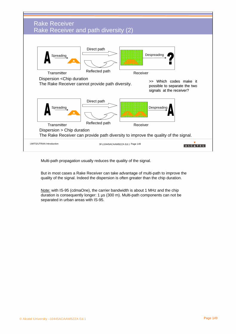
© Alcatel University –10445ACAAWBZZA Ed.1 Page 149
UMTS/UTRAN Introduction 3FL10445ACAAWBZZA Ed.1 Page 149
Rake ReceiverRake Receiver and path diversity (2)
Dispersion > Chip durationThe Rake Receiver can provide path diversity to improve the quality of the signal.
ReceiverTransmitter
Spreading Despreading
Direct path
Reflected path
ReceiverTransmitter
Spreading Despreading
Direct path
Reflected path
Dispersion <Chip durationThe Rake Receiver cannot provide path diversity. >> Which codes make it >> Which codes make it
possible to separate the two possible to separate the two signals at the receiver?signals at the receiver?
Multi-path propagation usually reduces the quality of the signal.
But in most cases a Rake Receiver can take advantage of multi-path to improve the quality of the signal. Indeed the dispersion is often greater than the chip duration.
Note: with IS-95 (cdmaOne), the carrier bandwidth is about 1 MHz and the chip duration is consequently longer: 1 µs (300 m). Multi-path components can not be separated in urban areas with IS-95.

© Alcatel University –10445ACAAWBZZA Ed.1 Page 150
4. WCDMA in UMTS
4.7 Power Control

© Alcatel University –10445ACAAWBZZA Ed.1 Page 151
UMTS/UTRAN Introduction 3FL10445ACAAWBZZA Ed.1 Page 151
Power ControlWhy ?
Iub
Serving RNC
Main Problem : If the interference level is to high, it is not possible to decode the signal.
f
P
ISCP or NoSIR
PG
Eb
RSCP or Ec
At Node B reception level
In UTRA/FDD, the power control is a key functionality : the users usingsimultaneously the same frequency band interfere each other.The transmit power must be dynamically adapted in order to
Enable to reach the quality of serviceCompensate fading occurrencesAvoid interfering other users (and thus decreasing the system capacity)
Two main power control algorithms can be distinguished:Open-loop power control (UL only)Closed loop power control (UL/DL)

© Alcatel University –10445ACAAWBZZA Ed.1 Page 152
UMTS/UTRAN Introduction 3FL10445ACAAWBZZA Ed.1 Page 152
Power ControlDifferent kinds of Power Control
Physical channels:
• Not associated with transport channels
(Physical signaling)
• Associated with transport channels
• Dedicated channels
• Common channels
Channel power fixed and set by the operator
Open Loop Power Control
Closed Loop power control

© Alcatel University –10445ACAAWBZZA Ed.1 Page 153
UMTS/UTRAN Introduction 3FL10445ACAAWBZZA Ed.1 Page 153
Power ControlOpen Loop
If UE receives a STRONG DL signal,then UE will speak low.
1
2
1
2
If UE receives a weak DL signal,then UE will speak LOUD.
Fading is not correlated on UL and DL due to separation of UL and DL band.Open loop Power Control is not enough fast and accurate for the dedicated traffic.
Open Loop Power Control
Basic mechanism:PC is intended to reduce the interference level in the system by maintaining the quality if theUE-UTRAN radio link as close as possible to the minimum quality required for thetype of service requested.
How is Power Control performed ?- Open loop power control (also called slow power control):it consists for the mobile station of making a rough estimate of path loss by means of aDL beacon signal and adding the interference level of the Node-B and a constant value.It’s far too inaccurate and only used to provide a coarse initial power setting of the mobilestation at the beginning of a connection
- Closed-loop power control:See next slide

© Alcatel University –10445ACAAWBZZA Ed.1 Page 154
UMTS/UTRAN Introduction 3FL10445ACAAWBZZA Ed.1 Page 154
Power ControlClosed Loop PC : Principles
IubRNC
Outer Closed Loop Inner Closed Loop
• SIR Estimation
• Comparaison between SIRestand SIRtarget
• Generation of a TCP command: increase or descreaseOn each Time slot !
1500 Hz...
”Power down”
”Power up”
”Power down”
”Power ...”
***
***
***
***
***
SIR target
Error measurements
The Node-B controls the power of the UE (and vice versa) by performing a SIR estimation (inner loop) and by generating TPC command for each time slot of the radio frame.
The RNC controls parameters of the SIR estimation (outer loop) and set the initial SIR target, defined by the operator and modify it according to the error measurement reports.
Closed Loop Power Control
Inner Loop (Fast Loop Power Control)In UL, the serving cells should estimate signal-to-interference ratio SIRest
of the received uplink DPCH. The serving cells should then generate TPC commandsand transmit the commands once per slot according to the following rule: if SIRest > SIRtarget
then the TPC command to transmit is "0" , while if SIRest < SIRtarget then the TPC command to transmit is "1".Upon reception of one or more TPC commands in a slot, the UE shall derive a singleTPC command, TPC_cmd, for each slot, combining multiple TPC commands if morethan one is received in a slot. TPC_cmd values = +1(power up), -1 (power down), 0The step size ∆TPC is under the control of the UTRAN (value = 1 dB or 2 dB)UE shall adjust the transmit power of the uplink DPCCH with a step of ∆DPCCH (in dB)which is given by ∆DPCCH = ∆TPC × TPC_cmd.The command rate of 1500Hz is faster than any significant change of path loss.
Outer Loop The RNC checks the quality of the signal using for example a CRC-based approach(Cyclic Redundancy Check) and uses this result to adjust SIR target for the inner loop.The big issue is to meet constantly the required quality: no worse and also no better,because it would be a waste of capacity. The required quality may change with the multi-path profile (related to the environment)and with the UE speed.The outer loop management is handled by the CRNC because a soft HO may be performed.Frequency of the outer loop: 10-100 Hz typically
Note: in GSM only slow power control is employed (about 2 Hz)

© Alcatel University –10445ACAAWBZZA Ed.1 Page 155
UMTS/UTRAN Introduction 3FL10445ACAAWBZZA Ed.1 Page 155
Power ControlClosed Loop PC : Power Density
f
P
ISCP or No
SIR estEb
RSCP or Ec
At Node B reception level
Assuming a user using a service.
It is initial SIR target is 3dB.
The error ratio required is 0.01 .
Several error ratio reports are between 0.002 and 0.007
How do the SIR target evoluate ?
What is the impact on the user or on the system if the estimated SIR is too high ? Too small ?
Iub
RNC
SIR target
Error measurements...
”Power up”
”Power ...”
SIR Target

© Alcatel University –10445ACAAWBZZA Ed.1 Page 156
UMTS/UTRAN Introduction 3FL10445ACAAWBZZA Ed.1 Page 156
Power ControlUL Closed Loop PC, in case of Soft Handover
Iub
What is the behaviour of the UE in UL in case of soft handover ?
• The UE takes in to account all the command according to the 3GPP
P(t)=P(t-1) + F(TPC1(t) + TPC2(t))
The function F(TPC(t)) is implemented by the UE manufacturer.
F(TPC(t))=min(TCP1(t), …, TPCi(t))
With i= number of involved Node B
Power up !!! TPC=1
Power down !!! TPC=-1
???
1 2

© Alcatel University –10445ACAAWBZZA Ed.1 Page 157
UMTS/UTRAN Introduction 3FL10445ACAAWBZZA Ed.1 Page 157
Power ControlDL Closed Loop PC, in case of Soft Handover
Iub
What is the behaviour of the Node B involedin the call in DL in case of soft handover ?
• The UE sends the same command for all the Node B involved.
Node Bs must transmit data with the same power for a user
• Due to reception errors their power can shift themselves
A mechanism, the DL Power Balancing, allows to readjust the transmission power of the Node B.
The SRNC selects the best radio link, and readjust, step by step, the transmission power.
P(t) = P(t-1) + Ptpc(t) + Pbal(t)
Power up !!! TPC=1
Power up
Power up

© Alcatel University –10445ACAAWBZZA Ed.1 Page 158
4. WCDMA in UMTS
4.8 Coverage, Capacity & Quality

© Alcatel University –10445ACAAWBZZA Ed.1 Page 159
UMTS/UTRAN Introduction 3FL10445ACAAWBZZA Ed.1 Page 159
Coverage, Capacity & QualityLinks between the Coverage, the Capacity and the Quality
Example: Increase the quality in UL
How to do ?
• Decrease the error ratio at the Node B level
• So increase the SIR at the Node B level
• So the UEs use more power
Impacts !
• Increasement of the UL Interference level
• So decrease of the cell size
• And decrease of the high data rate with need more power in transmission (capacity).
RNC
Node B
Iub
f
P
SIR
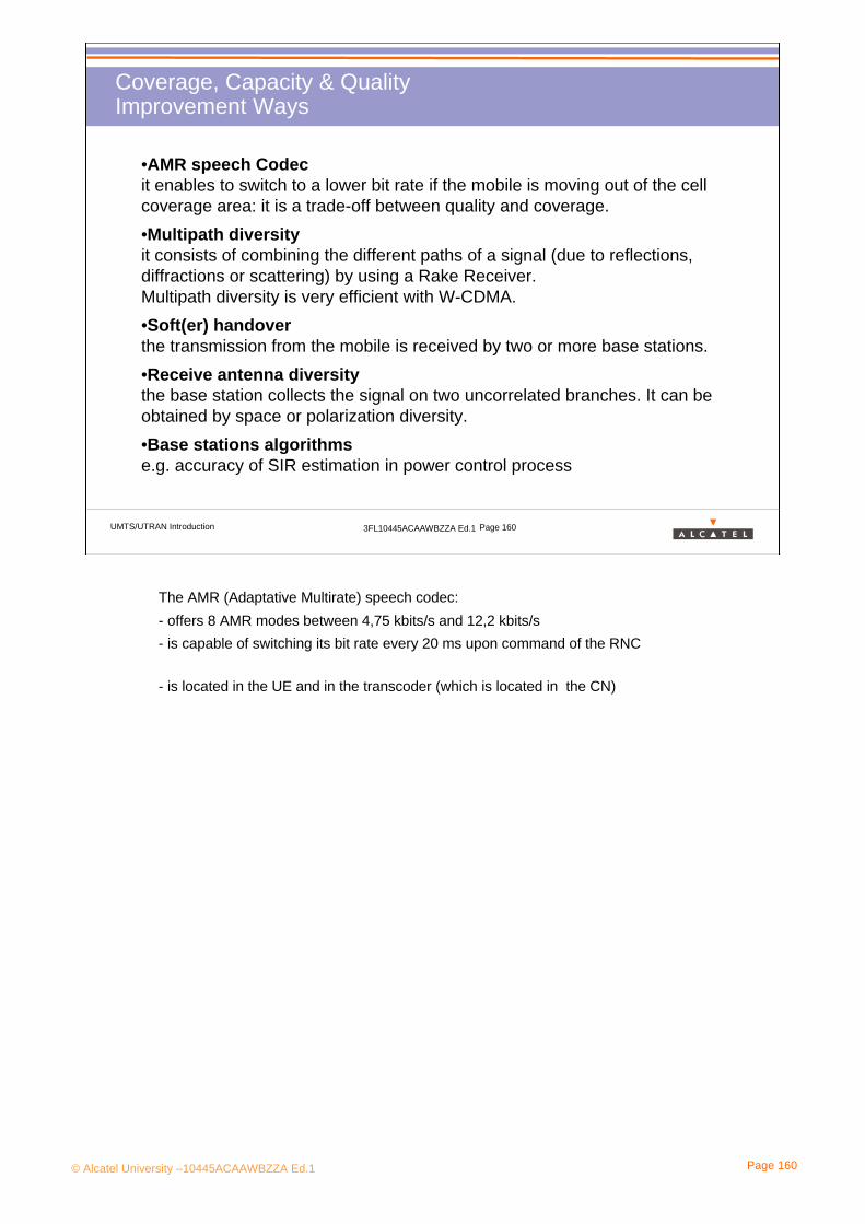
© Alcatel University –10445ACAAWBZZA Ed.1 Page 160
UMTS/UTRAN Introduction 3FL10445ACAAWBZZA Ed.1 Page 160
Coverage, Capacity & QualityImprovement Ways
•AMR speech Codecit enables to switch to a lower bit rate if the mobile is moving out of the cell coverage area: it is a trade-off between quality and coverage.•Multipath diversityit consists of combining the different paths of a signal (due to reflections, diffractions or scattering) by using a Rake Receiver.Multipath diversity is very efficient with W-CDMA.•Soft(er) handoverthe transmission from the mobile is received by two or more base stations.•Receive antenna diversitythe base station collects the signal on two uncorrelated branches. It can be obtained by space or polarization diversity.•Base stations algorithmse.g. accuracy of SIR estimation in power control process
The AMR (Adaptative Multirate) speech codec:- offers 8 AMR modes between 4,75 kbits/s and 12,2 kbits/s- is capable of switching its bit rate every 20 ms upon command of the RNC
- is located in the UE and in the transcoder (which is located in the CN)

© Alcatel University –10445ACAAWBZZA Ed.1 Page 161
UMTS/UTRAN Introduction 3FL10445ACAAWBZZA Ed.1 Page 161
Coverage, Capacity & QualityTypical Values
Quality: The quality is measured with the Block Error Ratio (BLER). Here some example according different services.
Coverage:
• Dense Urban Cell: about 300 meters
• SubUrban Cell: about 1 km
•Rural Cell: 3 km
Capacity:
The main limitation is the interference level due to the WCDMA technology.
But the system is also limited by capacity processing of the Node B and the RNC, by the codes, and by the transmission capacity.
0.10.01 0.01
DCCH
0.01
PS384
0.01
PS128
0.01
PS64
0.01 0.001
CS64
0.001
AMR
Target BLER

© Alcatel University –10445ACAAWBZZA Ed.1 Page 162
5. UTRAN Scenario

© Alcatel University –10445ACAAWBZZA Ed.1 Page 163
UMTS/UTRAN Introduction 3FL10445ACAAWBZZA Ed.1 Page 163
UTRAN ScenarioContent
> Objective: to be able to build the map of the radio channels (logical, transport and physical) from a white paper.
> Program:
• 5.1 Radio Channels Mapping • 5.2 Service Request• 5.3 RAB Establishment• 5.4 Mobility Management in connected mode

© Alcatel University –10445ACAAWBZZA Ed.1 Page 164
UMTS/UTRAN Introduction 3FL10445ACAAWBZZA Ed.1 Page 164
UTRAN ScenarioIntroduction 1/3
Iub
Serving RNC
CNCollection of System Informatin
System Information
RRC Connection
RRC ConnectionIMSI Attachment
IMSI Attachment
Paging
Paging
The UE is switched on !
What happen ?

© Alcatel University –10445ACAAWBZZA Ed.1 Page 165
UMTS/UTRAN Introduction 3FL10445ACAAWBZZA Ed.1 Page 165
UTRAN ScenarioIntroduction 2/3
Iub
Serving RNC
CN
The UE requests a service.
How and in which conditions are the resources required setup ?
Admission Control
? RAB Establishment
RAB
Traffic Managment

© Alcatel University –10445ACAAWBZZA Ed.1 Page 166
UMTS/UTRAN Introduction 3FL10445ACAAWBZZA Ed.1 Page 166
UTRAN ScenarioIntroduction 3/3
Iub
Serving RNC
CN
The UE uses a service and moves !
How UTRAN can provide the service despite the mobility ?
A new radio is added
Hard Handover on anthere FDD carrierInter RAT Handover
BSCBTS

© Alcatel University –10445ACAAWBZZA Ed.1 Page 167
5. UTRAN Scenario
5.1 Radio Channels Mapping

© Alcatel University –10445ACAAWBZZA Ed.1 Page 168
UMTS/UTRAN Introduction 3FL10445ACAAWBZZA Ed.1 Page 168
Radio Channels MappingDownlink
Logical Ch
Transport Ch
Physical Ch
AICHNot associated with transport channels PICH CPICH P-SCH S-SCH
PDSCH S-CCPCH P-CCPCHDPDCH
+ DPCCH
DTCH, DCCH CCCH, CTCH
DCH BCHPCHFACHDSCH
Not implemented yet in EvoliumTM
Solution
PCCH BCCH
DPDCH and DPCCH multiplexed by time
Common Physical ChDedicated Physical Ch
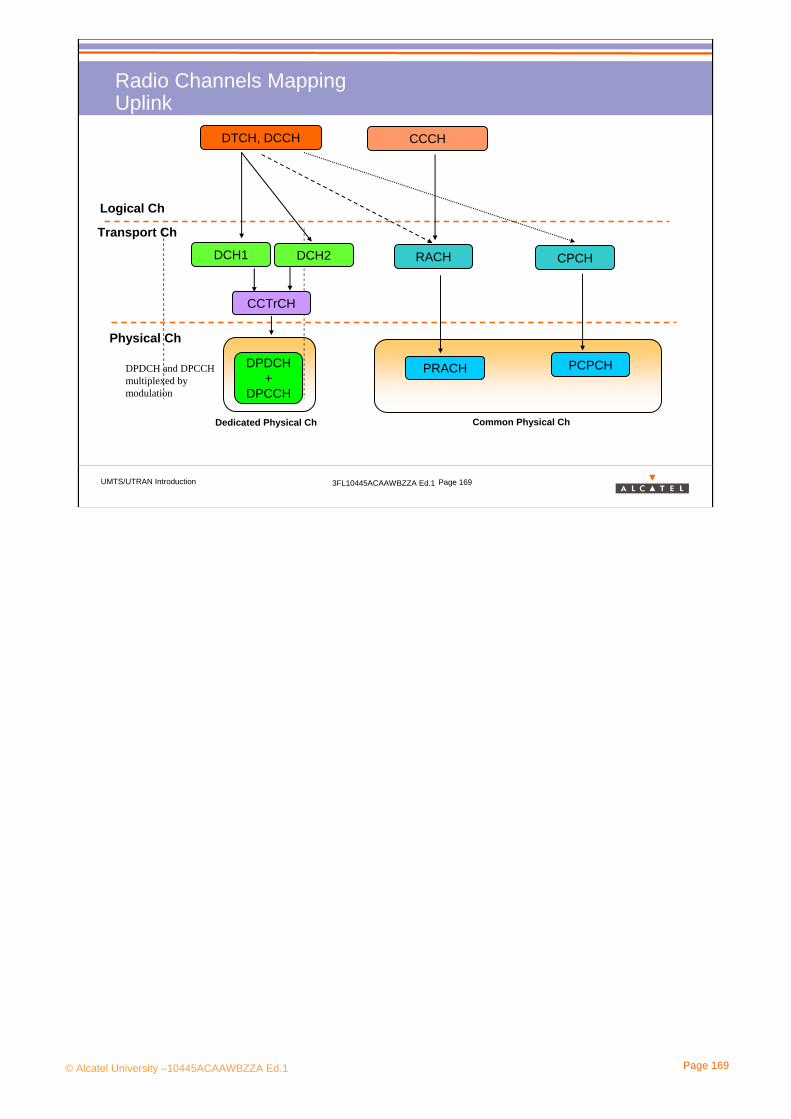
© Alcatel University –10445ACAAWBZZA Ed.1 Page 169
UMTS/UTRAN Introduction 3FL10445ACAAWBZZA Ed.1 Page 169
Radio Channels MappingUplink
Logical Ch
Transport Ch
Physical Ch
PRACH PCPCHDPDCH +
DPCCH
DTCH, DCCH CCCH
DCH1 RACHDCH2
CCTrCH
CPCH
DPDCH and DPCCH multiplexed by modulation
Dedicated Physical Ch Common Physical Ch

© Alcatel University –10445ACAAWBZZA Ed.1 Page 170
5. UTRAN Scenario
5.2 Service Request
© Alcatel University –10445ACAAWBZZA Ed.1 Page 171
UMTS/UTRAN Introduction 3FL10445ACAAWBZZA Ed.1 Page 171
Service RequestContent
> Program:
• 5.2.1 System Information Collection• 5.2.2 RRC Connection• 5.2.3 IMSI Attachment & Location Update• 5.2.4 Paging

© Alcatel University –10445ACAAWBZZA Ed.1 Page 172
5. UTRAN Scenario
5.2 Service Request5.2.1 System Information Collection

© Alcatel University –10445ACAAWBZZA Ed.1 Page 173
UMTS/UTRAN Introduction 3FL10445ACAAWBZZA Ed.1 Page 173
System Information CollectionPrinciples
Iub
Serving RNC
CN• The UE synchronize itself at the slot on the P-SCH
• UE synchronize itself at the frame level on the S-SCH and retrieve a group of 8 Scrambling codes.
•The UE test the 8 SC on the CPICH to find the SC of the cell
•The UE decode the BCH channel to read the system information
•The UE select the best cell
???
Just after the switch on, the UE can decode only the P-SCH and S-SCH if it is on acovered area

© Alcatel University –10445ACAAWBZZA Ed.1 Page 174
UMTS/UTRAN Introduction 3FL10445ACAAWBZZA Ed.1 Page 174
System Information CollectionP-SCH & S-SCH
P-CCPCH Radio Frame 10 ms
Slot #0 Slot #1 Slot #14
acpP-SCH
S-SCH acs1
…acp acp
acs2 acs14
The SCH is time-multiplexed with the P-CCPCH (which carries the BCH) and consists of 2 sub-channels.
• The Primary SCH (P-SCH) made of always the slot on all the FDD Cells. The UE uses it to acquire the slot synchronization to a cell.
•The Secondary SCH (S-SCH) contains a sequence of 15 codes which identifies the Code Group of the Downlink Scrambling Code (DL SC) of the cell. The UE uses it to acquire the frame synchronization to a cell and to identify the Code Group of the DL SC.
256 chips
Cell Search Procedure (also called synchronization procedure)3GPP TS 25.214 provides an informative description how it is typically done
Step 1: slot synchronizationIn all the cell of any PLMN, the P-SCH is made of a unique & same primary codesequence of 256 chips repeated at each Time Slot Occurrence.This is typically done with a single matched filter (or any similar device) to the primarysynchronisation code which is common to all cells. The slot timing of the cell can beobtained by detecting peaks in the matched filter output.
Step 2: frame synchronization and code-group identificationA S-SCH is made of 15 repetitions of a secondary code sequence of 256 chips(one per Time Slot) transmitted in perfect synchronization with the P-SCHcode sequences. The UTRAN used 64 distinct secondary synchronization code sequences (reused in distant cells of the UTRAN).This is done by correlating the received signal with all possible secondary synchronisationcode sequences, and identifying the maximum correlation value. Since the cyclic shifts of thesequences are unique the code group as well as the frame synchronisation is determined.
Each secondary code sequence corresponds to a unique group of 8 possible Primary Scrambling codes
Step 3: (downlink) scrambling code identificationThe UE determines the (primary) scrambling code used by the found cell throughsymbol-by-symbol correlation over the CPICH (pilot) with all codes within the Code Groupidentified in the step 2 (8 possibilities). Afterwards the P-CCPCH can be detected and the system- and cell specific BCHinformation can be read.
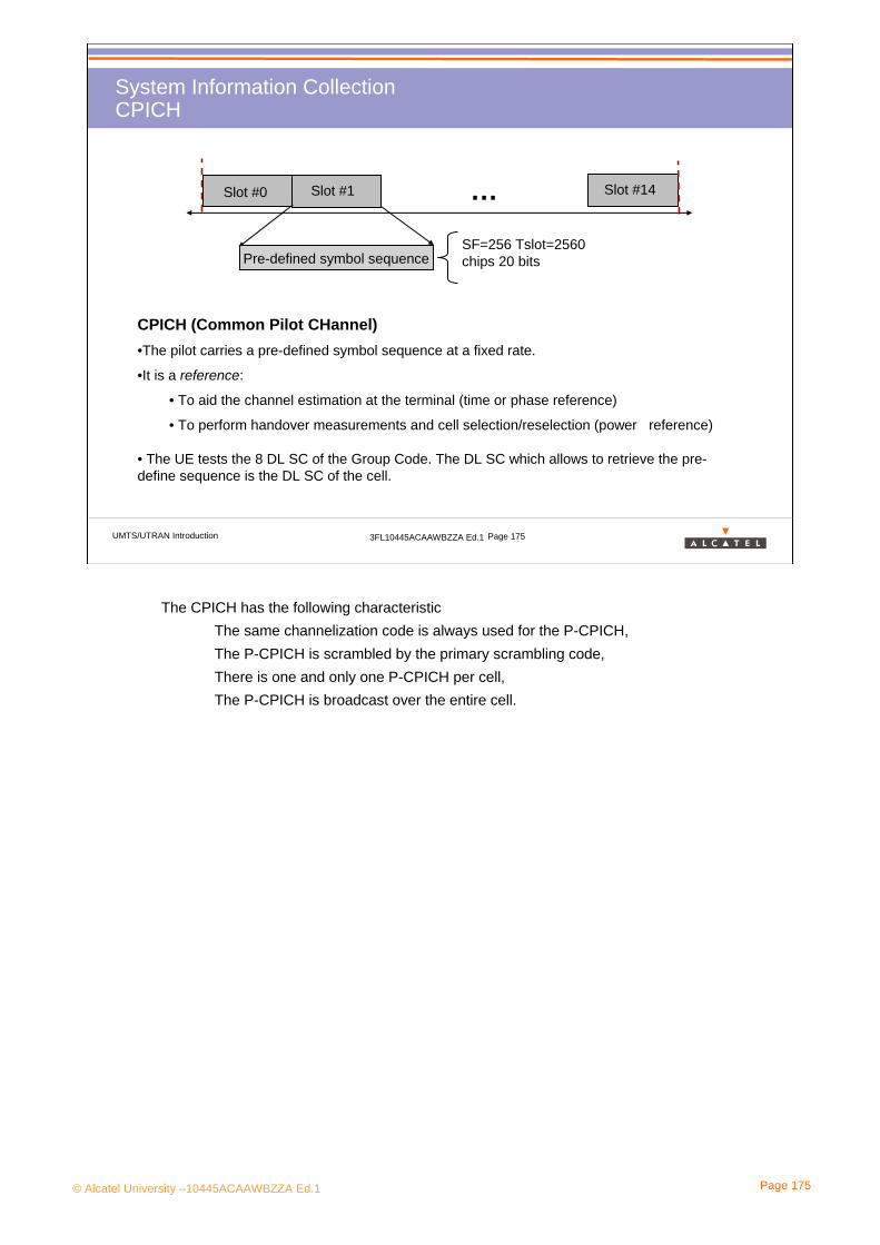
© Alcatel University –10445ACAAWBZZA Ed.1 Page 175
UMTS/UTRAN Introduction 3FL10445ACAAWBZZA Ed.1 Page 175
System Information CollectionCPICH
…Slot #0 Slot #1 Slot #14
Pre-defined symbol sequence
CPICH (Common Pilot CHannel)•The pilot carries a pre-defined symbol sequence at a fixed rate.
•It is a reference:
• To aid the channel estimation at the terminal (time or phase reference)
• To perform handover measurements and cell selection/reselection (power reference)
• The UE tests the 8 DL SC of the Group Code. The DL SC which allows to retrieve the pre-define sequence is the DL SC of the cell.
SF=256 Tslot=2560 chips 20 bits
The CPICH has the following characteristicThe same channelization code is always used for the P-CPICH,The P-CPICH is scrambled by the primary scrambling code,There is one and only one P-CPICH per cell,The P-CPICH is broadcast over the entire cell.
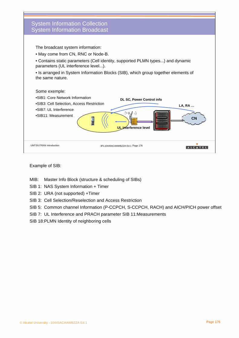
© Alcatel University –10445ACAAWBZZA Ed.1 Page 176
UMTS/UTRAN Introduction 3FL10445ACAAWBZZA Ed.1 Page 176
System Information CollectionSystem Information Broadcast
The broadcast system information:• May come from CN, RNC or Node-B. • Contains static parameters (Cell identity, supported PLMN types...) and dynamic parameters (UL interference level...).• Is arranged in System Information Blocks (SIB), which group together elements of the same nature.
Some exemple:•SIB1: Core Network Information •SIB3: Cell Selection, Access Restriction•SIB7: UL Interference•SIB11: Measurement
CN
LA, RA …
DL SC, Power Control info
UL interference level
Example of SIB:
MIB: Master Info Block (structure & scheduling of SIBs)SIB 1: NAS System Information + TimerSIB 2: URA (not supported) +Timer SIB 3: Cell Selection/Reselection and Access RestrictionSIB 5: Common channel Information (P-CCPCH, S-CCPCH, RACH) and AICH/PICH power offsetSIB 7: UL Interference and PRACH parameter SIB 11:MeasurementsSIB 18:PLMN Identity of neighboring cells

© Alcatel University –10445ACAAWBZZA Ed.1 Page 177
UMTS/UTRAN Introduction 3FL10445ACAAWBZZA Ed.1 Page 177
System Information CollectionSystem Information Broadcast
The broadcast system information can be carried on BCH which is transmitted permanently over the entire cell.
Transport Ch.
Logical Ch.
Physical Ch.
BCCH
BCH
P-CCPCH
The broadcast system information is made of 128 periodic radio frame. So its period is 1280 ms. There are a Master SIB or MIB and several SIB (System Information Block) organised by domain.
Frame #0 Frame #1 Frame #2
Frame #i-1 Frame #i Frame #i+1
Frame #125 Frame #126 Frame #127
MIB SIB3 SIB11
SIB5 SIB7 MIB
SIB5SIB11 SIB7
…
……
…
Thanks to this channel, the UE is able to retrieve information allowing the request of a RRC connection like the Channelization code used on the uplink common channel

© Alcatel University –10445ACAAWBZZA Ed.1 Page 178
UMTS/UTRAN Introduction 3FL10445ACAAWBZZA Ed.1 Page 178
System Information CollectionProcedure
System Information Update Request
Master/Segment Info Block(s), BCCH modification time
Master/Segment Info Block(s)System Information (BCCH:BCH)
UE Node-B RNC
RRC RRC
NBAP
CN
Master/Segment Info Block(s)System Information (BCCH:BCH)
RRC RRC
Master/Segment Info Block(s)System Information (BCCH:BCH)
RRC RRC
System Information Update Response
NBAP NBAP
>> Why does RRC protocol >> Why does RRC protocol terminate at Nodeterminate at Node--B for BCH B for BCH
(not at RNC)?(not at RNC)?
NBAP
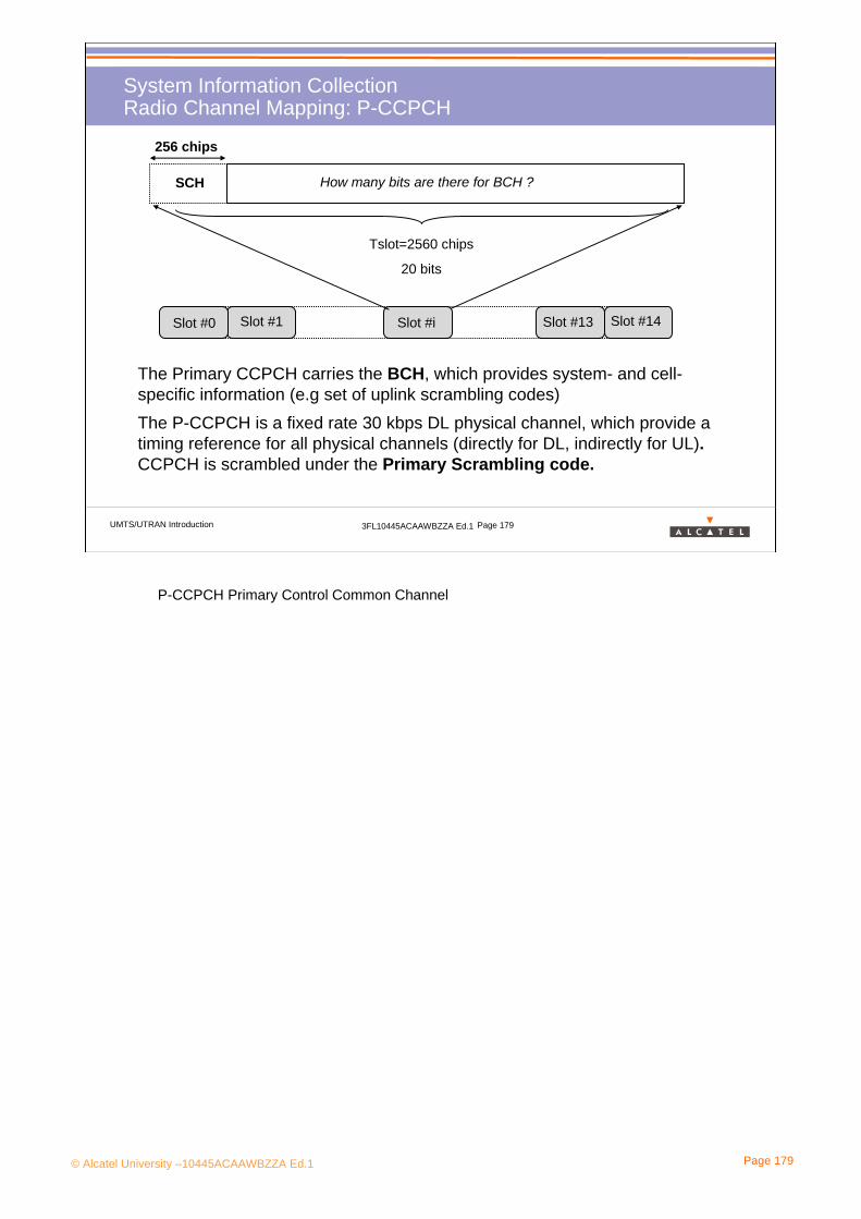
© Alcatel University –10445ACAAWBZZA Ed.1 Page 179
UMTS/UTRAN Introduction 3FL10445ACAAWBZZA Ed.1 Page 179
System Information CollectionRadio Channel Mapping: P-CCPCH
The Primary CCPCH carries the BCH, which provides system- and cell-specific information (e.g set of uplink scrambling codes)The P-CCPCH is a fixed rate 30 kbps DL physical channel, which provide a timing reference for all physical channels (directly for DL, indirectly for UL).CCPCH is scrambled under the Primary Scrambling code.
Slot #0 Slot #1 Slot #13 Slot #14Slot #i
SCH
Tslot=2560 chips
20 bits
256 chips
How many bits are there for BCH ?
P-CCPCH Primary Control Common Channel

© Alcatel University –10445ACAAWBZZA Ed.1 Page 180
UMTS/UTRAN Introduction 3FL10445ACAAWBZZA Ed.1 Page 180
Cell SelectionPrinciples
Iub
RNC
CN
???
Now, the UE can read the BCH of one cell.
But this cell is not necessary the best because the SCH has been chosen randomly.
The UE compares the cells to be camped on the best one.
There are 2 criterion:
• QRxLev, from the CPICH RSCP, to estimate the reception level.
• Qqual, from the CPICH Ec/No, to estimate the quality of reception. It takes in account the interference level.
When a UE is not connected, like here, and is moving, it has to reselect regularly the best cell for itself. To protect some cells, it is possible to facilitate or not the selection of one cell.

© Alcatel University –10445ACAAWBZZA Ed.1 Page 181
5. UTRAN Scenario
5.2 Service Request5.2.2 RRC Connection

© Alcatel University –10445ACAAWBZZA Ed.1 Page 182
UMTS/UTRAN Introduction 3FL10445ACAAWBZZA Ed.1 Page 182
RRC ConnectionWhy ?
The UE is switched on and has selected a cell.
The UE is in idle mode.
•UTRAN doesn’t know anything about this UE.
•The UE hasn’t UTRAN identifier neither Scrambling and Channelization code.
The UE can’t exchange any data with UTRAN.
To be known by UTRAN and to use dedicated radio resources, the UE has to be RRC connected.
After, the UE can attach its IMSI or update its location to the Core Network and can request a service
Iub
RNC
CN
RRC Connected
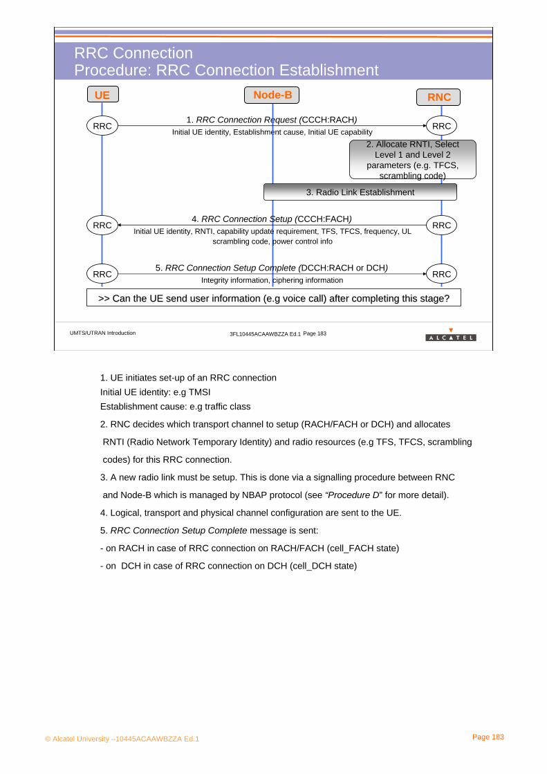
© Alcatel University –10445ACAAWBZZA Ed.1 Page 183
UMTS/UTRAN Introduction 3FL10445ACAAWBZZA Ed.1 Page 183
RRC ConnectionProcedure: RRC Connection Establishment
Initial UE identity, Establishment cause, Initial UE capability1. RRC Connection Request (CCCH:RACH)
UE
RRC RRC
3. Radio Link Establishment
Initial UE identity, RNTI, capability update requirement, TFS, TFCS, frequency, UL scrambling code, power control info
4. RRC Connection Setup (CCCH:FACH)RRC RRC
Integrity information, ciphering information5. RRC Connection Setup Complete (DCCH:RACH or DCH)
RRC RRC
2. Allocate RNTI, Select Level 1 and Level 2
parameters (e.g. TFCS, scrambling code)
>> Can the UE send user information (e.g voice call) after compl>> Can the UE send user information (e.g voice call) after completing this stage?eting this stage?
Node-B RNC
1. UE initiates set-up of an RRC connectionInitial UE identity: e.g TMSI Establishment cause: e.g traffic class
2. RNC decides which transport channel to setup (RACH/FACH or DCH) and allocates
RNTI (Radio Network Temporary Identity) and radio resources (e.g TFS, TFCS, scrambling
codes) for this RRC connection.
3. A new radio link must be setup. This is done via a signalling procedure between RNC
and Node-B which is managed by NBAP protocol (see “Procedure D” for more detail).
4. Logical, transport and physical channel configuration are sent to the UE.
5. RRC Connection Setup Complete message is sent:
- on RACH in case of RRC connection on RACH/FACH (cell_FACH state)
- on DCH in case of RRC connection on DCH (cell_DCH state)

© Alcatel University –10445ACAAWBZZA Ed.1 Page 184
UMTS/UTRAN Introduction 3FL10445ACAAWBZZA Ed.1 Page 184
RRC ConnectionProcedure: RRC Connection Release
RRC RRC4. RRC Connection Release (DCCH:DCH )
Cause
RANAP RANAP
1. Iu Release Command
Cause
RANAP RANAP
2. Iu Release Complete
-
3. ALCAP Iu Bearer Release
RRC RRC5. RRC Connection Release Complete (DCCH:DCH )
-
6. Radio Link Deletion
7. Radio Link Deletion
8. Radio Link Deletion
UE Node-B(DRNC)
SRNCDRNC CNNode-B(SRNC)
In this example, the UE is in macro-diversity on two Node-Bs from two different RNCs.
Therefore the UE could only be in cell_DCH state (soft HO is only possible on DCH)
1. The CN initiates the release of RRC connection
2. -
3. SRNC initiates release of Iu Bearer using ALCAP protocol
4. -
5. -
6. SRNC initiates release of radio link (for Node-B of SRNC) using NBAP protocol
7. SRNC requires release of radio link (for Node-B of DRNC) to DRNC using RNSAP protocol
8. DRNC initiates release of radio link (for Node-B of DRNC) using NBAP protocol

© Alcatel University –10445ACAAWBZZA Ed.1 Page 185
UMTS/UTRAN Introduction 3FL10445ACAAWBZZA Ed.1 Page 185
RRC ConnectionHow to contact UTRAN: the PRACH Channel 1/2
Iub
RNCFor the initial access, the UE has to use a common uplink channel called the PRACH
Every UE use this channel to request a connection. If 2 UEs request on the time there is collision, and UTRAN receives nothing.
To manage this problem, the UE sends a first message called preamble until it receives a response on a downlink channel called AICH.
After the response on the AICH, the UE sends its message (the request) on the PRACH.
Hello !
Preamble on the PRACH
Yes ! Response on the AICH
HELLO!I need a connection
Message part
PRACH= Physical Random Access ChannelAICH= Acquisition Indicator channel
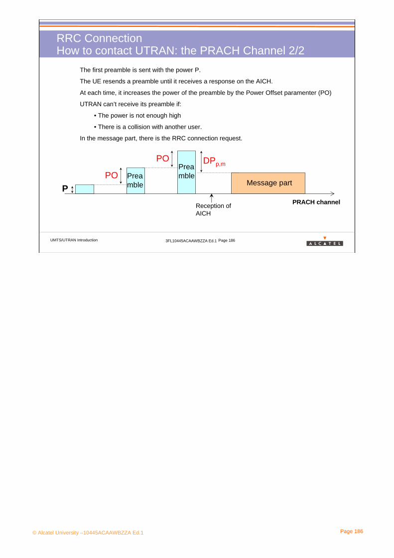
© Alcatel University –10445ACAAWBZZA Ed.1 Page 186
UMTS/UTRAN Introduction 3FL10445ACAAWBZZA Ed.1 Page 186
RRC ConnectionHow to contact UTRAN: the PRACH Channel 2/2
Preamble
Preamble
Message part
DPp,mPO
Reception of AICH
POP
PRACH channel
The first preamble is sent with the power P.
The UE resends a preamble until it receives a response on the AICH.
At each time, it increases the power of the preamble by the Power Offset paramenter (PO)
UTRAN can’t receive its preamble if:
• The power is not enough high
• There is a collision with another user.
In the message part, there is the RRC connection request.

© Alcatel University –10445ACAAWBZZA Ed.1 Page 187
UMTS/UTRAN Introduction 3FL10445ACAAWBZZA Ed.1 Page 187
RRC ConnectionUE Status 1/3
UE
detached
UE
in idle mode
UE
in connected
mode
RRC Connection Release
RRC Connection Establishment
out of coverage
“just after switch on” process
Including Cell search procedure
Just after the switch on, the UE has to attach its IMSI. Thanks to his procedure the Core Network knows, the UE is on the network and where it is located at the Location or routing area level.
Several sub-status in the connected
mode
To attach its IMSI and update its location the UE has to be in connected mode, so it has to request a RRC Connection
•Just after switch on” process contains:•Cell selection (including cell search procedure) •PLMN selection•Attachment procedure (see “Appendix” for more details)
• The UE must enter the connected mode to transmit signalling or traffic data to the network
•What is the relationship with the states of the mobile phone in GSM?
The two GSM states, idle mode and connected mode, are similar to idle mode and cell_DCH state in UMTS.
•What is the relationship with the states of the mobile phone in GPRS?
There is no correspondence between GPRS states (idle, standby and ready) and UMTS states.
Indeed there is no notion of connection on GPRS.

© Alcatel University –10445ACAAWBZZA Ed.1 Page 188
UMTS/UTRAN Introduction 3FL10445ACAAWBZZA Ed.1 Page 188
RRC ConnectionUE Status 2/3
Cell DCH
Cell FACH
URA PCH
Cell PCH
UE
in idle
mode
UE in connected mode
Cell_DCH state
Signalling and traffic data dedicated to the UE (mapped on DCCH and DTCH respectively) are carried on DCH transport channel
Cell_FACH state
Signalling and traffic data dedicated to the UE (mapped on DCCH and DTCH respectively) are carried on RACH (uplink) and FACH(downlink) transport channels
Cell_DCH ⇒Cell_FACHNo traffic UL/DL at expiry of timer 1
Cell_FACH ⇒Cell_DCHTraffic volume UL/DL too large
•The initial state of the UE is determined by the DCCH established during RRC connection establishment:- if the DCCH is mapped on a DCH, the UE is in cell_DCH state- if the DCCH is mapped on RACH/FACH, the UE is in cell_FACH state
• The UE can move from one state to another during the time of the RRC connection.• Transitions between states are:
- based on traffic volume measurements and network load
- always triggered by UTRAN signalling
Note: in cell_DCH state, the DSCH transport channel can also be used.

© Alcatel University –10445ACAAWBZZA Ed.1 Page 189
UMTS/UTRAN Introduction 3FL10445ACAAWBZZA Ed.1 Page 189
RRC ConnectionUE Status 3/3
Cell DCH
Cell FACH
URA PCH
Cell PCH
UE
in idle
mode
UE in connected mode
Cell_PCH state
No transmission of signalling and traffic data dedicated to the UE (no DCCH and no DTCH)
But the RRC connection is still active (UTRAN keeps RNTI for UE) and UE location at a cell level.
- a DCCH (and possibly a DTCH) can be reestablished very quickly (this procedure is initiated by sending a paging signal PCH)
URA_PCH state
Very similar to cell_PCH state
UTRAN keeps the location of the UE at the URA level (set of UMTS cells)
Cell_PCH ⇒ Cell_FACH ⇒URA_PCHToo many cell reselections
Cell_FACH ⇒Cell_PCHNo traffic UL/DL at expiry of timer 2
Cell/URA_PCH ⇒ Cell_FACHIncoming DL or UL traffic
•URA: UTRAN Registration Area (a small set of cells)
•Cell_PCH and URA_PCH states are needed for non real time services to optimise usage
of codes and battery consumption. It would not be efficient to allocate permanently a DCH
which would be used a very low percentage of time (Web application for example)
• What is the difference between idle mode, Cell_PCH and URA_PCH states?
In idle mode the location of the UE is not known by the UTRAN, but only by the CN at a
Location Area (LA) or Routing Area (RA) level (LA and RA and sets of cells larger than URA.
The paging message PCH must hence be sent in a LA or in a RA when the UE is in idle mode,
whereas it only needs to be sent in a cell in Cell_PCH state or in an URA when the UE is in
URA_PCH state (hence the paging procedure is much faster).

© Alcatel University –10445ACAAWBZZA Ed.1 Page 190
5. UTRAN Scenario
5.2 Service Request5.2.3 IMSI Attachment & Location
Update
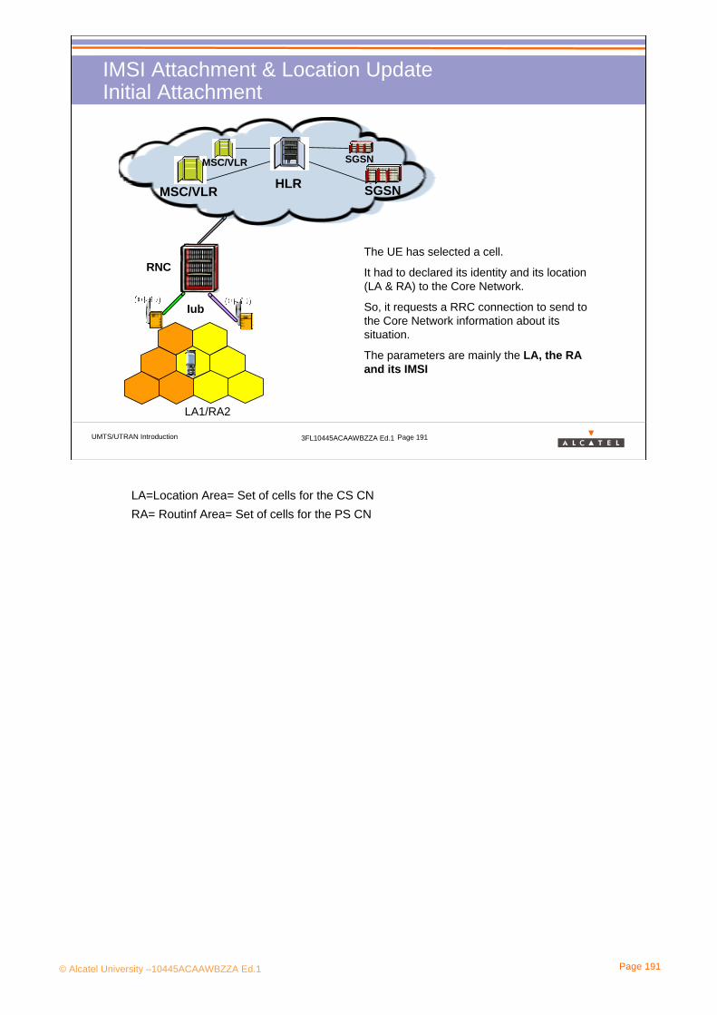
© Alcatel University –10445ACAAWBZZA Ed.1 Page 191
UMTS/UTRAN Introduction 3FL10445ACAAWBZZA Ed.1 Page 191
IMSI Attachment & Location UpdateInitial Attachment
HLR SGSNMSC/VLR
MSC/VLR SGSN
Iub
RNCThe UE has selected a cell.
It had to declared its identity and its location (LA & RA) to the Core Network.
So, it requests a RRC connection to send to the Core Network information about its situation.
The parameters are mainly the LA, the RA and its IMSI
LA1/RA2
LA=Location Area= Set of cells for the CS CNRA= Routinf Area= Set of cells for the PS CN

© Alcatel University –10445ACAAWBZZA Ed.1 Page 192
UMTS/UTRAN Introduction 3FL10445ACAAWBZZA Ed.1 Page 192
IMSI Attachment & Location UpdatePrinciples
When camping on a cell, the terminal must register its LA and/or its RA.
When the terminal moves across the network, it must update its LA (RA) which is stored in VLR (SGSN) in the Core Network.
LA (RA) Update is performed periodically or when entering a new LA (RA).
HLRSGSNMSC/VLR
Location Area (LA)
Routing Area (RA)
MSC/VLR SGSN
•LA and RA are managed on an independent way, but a RA must always be included in one LA(and not be divided into several different LAs).
• LA update is performed by the NAS layer MM (Mobility Management) located in UE and in MSC. • RA update is performed by NAS layer GMM (GPRS Mobility Management) located in UE and in SGSN.
• In the Core Network, the location information is stored on databases:- HLR (Home Location Register)It stores the master copy of user’s service profile, which consists of information on allowed services,forbidden roaming areas,… and which is created when a new user subscribes to the system.The HLR also stores the serving system (MSC/VLR and/or SGSN) where the terminal is located.
- VLR (Visitor Location Register)It serves the terminal in its current location for CS services and holds a copy of the visitinguser’s service profile.It stores the Location Area (LA) where the terminal is located.
- SGSN (Serving GPRS Support Node)It serves the terminal in its current location for PS services and holds a copy of the visitinguser’s service profile.It stores Routing Area (RA) where the terminal is located.
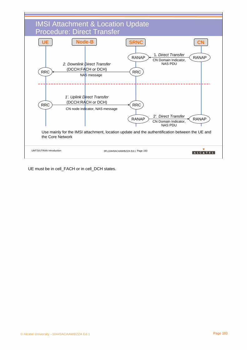
© Alcatel University –10445ACAAWBZZA Ed.1 Page 193
UMTS/UTRAN Introduction 3FL10445ACAAWBZZA Ed.1 Page 193
IMSI Attachment & Location UpdateProcedure: Direct Transfer
RANAP RANAP1. Direct Transfer
CN Domain Indicator, NAS PDU
RRC RRC
2. Downlink Direct Transfer (DCCH:FACH or DCH)
NAS message
RANAP RANAP2’. Direct TransferCN Domain Indicator,
NAS PDU
RRC RRC
1’. Uplink Direct Transfer (DCCH:RACH or DCH)CN node indicator, NAS message
UE Node-B SRNC CN
Use mainly for the IMSI attachment, location update and the authentification between the UE and the Core Network
UE must be in cell_FACH or in cell_DCH states.

© Alcatel University –10445ACAAWBZZA Ed.1 Page 194
5. UTRAN Scenario
5.2 Service Request5.2.4 Paging
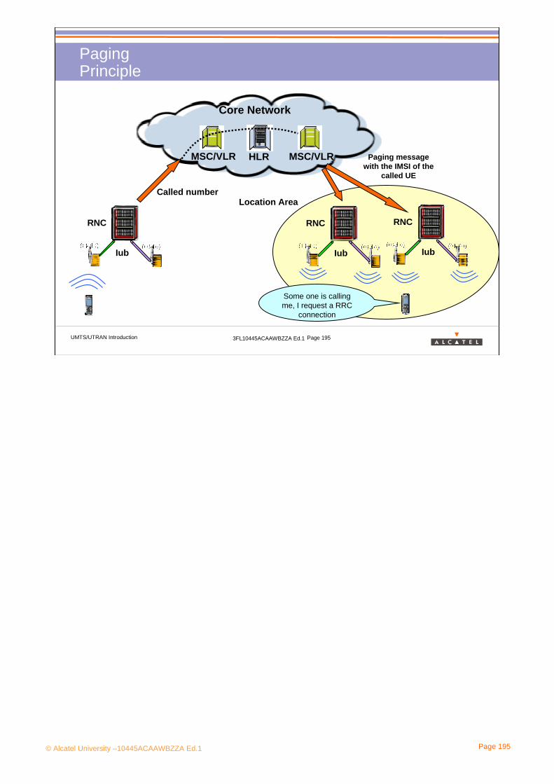
© Alcatel University –10445ACAAWBZZA Ed.1 Page 195
UMTS/UTRAN Introduction 3FL10445ACAAWBZZA Ed.1 Page 195
Paging Principle
Iub
RNC
Iub
RNC
Iub
RNC
Core Network
Called number
HLRMSC/VLR MSC/VLR Paging message with the IMSI of the
called UE
Location Area
Some one is calling me, I request a RRC
connection
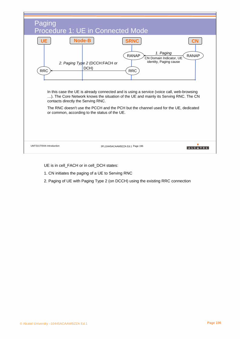
© Alcatel University –10445ACAAWBZZA Ed.1 Page 196
UMTS/UTRAN Introduction 3FL10445ACAAWBZZA Ed.1 Page 196
Paging Procedure 1: UE in Connected Mode
RANAP RANAP1. Paging
CN Domain Indicator, UE identity, Paging cause
RRC RRC
UE Node-B SRNC CN
2. Paging Type 2 (DCCH:FACH or DCH)
In this case the UE is already connected and is using a service (voice call, web-browsing …). The Core Network knows the situation of the UE and mainly its Serving RNC. The CN contacts directly the Serving RNC.
The RNC doesn’t use the PCCH and the PCH but the channel used for the UE, dedicated or common, according to the status of the UE.
UE is in cell_FACH or in cell_DCH states:
1. CN initiates the paging of a UE to Serving RNC
2. Paging of UE with Paging Type 2 (on DCCH) using the existing RRC connection

© Alcatel University –10445ACAAWBZZA Ed.1 Page 197
UMTS/UTRAN Introduction 3FL10445ACAAWBZZA Ed.1 Page 197
Paging Procedure 2: UE in Idle Mode
RRC RRC2. Paging Type 1 (PCCH:PCH)
RRC RRC2. Paging Type1 (PCCH:PCH)
RANAP RANAP1. Paging
CN Domain Indicator, UE identity, Paging cause
RANAP RANAP1. Paging
Idem
UE1 UE2 Node-B1 Node-B2 RNC1 RNC2 CN
When the is in idle mode, UTRAN doesn’t know where it is located and the Core Network knows its location at the LA or RA level. UTRAN uses the PCCH and the PCH radio channels.
UE is in idle mode:
1. CN initiates the paging of a UE over a LA (RA in PS domain) spanning, for example, two RNCs.
2. Paging of UE with Paging Type 1
LA: Location Area, RA: Routing Area (see subchapter “5.8 Mobility Management”)
A similar procedure applies to UE in cell_PCH or in URA_PCH states.

© Alcatel University –10445ACAAWBZZA Ed.1 Page 198
UMTS/UTRAN Introduction 3FL10445ACAAWBZZA Ed.1 Page 198
Paging Radio Channels: PICH & PCH
Iub
RNC
PICHS-CCPCH
PCH
PCCHThe UE doesn’t watch the S-CCPCH.
It watches the PICH (Page Indicator Channel) at regular and defined interval and look for its PI, for Paging Indicator.
The PI is baseb on the IMSI. Several UEs can have the same PI.
When the UE find its PI on the PICH, it watches the S-CCPCH to check if it is for it and what is the cause.
Then it requests on RRC connection to have a RAB.
Logical Ch
Transport Ch
Physical Ch
MAC
Physical layer
In RNC
In Node B
PICHS-CCPCH
.
PI
PI
PI
..Paging message

© Alcatel University –10445ACAAWBZZA Ed.1 Page 199
5. UTRAN Working
5.3 RAB Establishment
© Alcatel University –10445ACAAWBZZA Ed.1 Page 200
UMTS/UTRAN Introduction 3FL10445ACAAWBZZA Ed.1 Page 200
Procedure between the switching on and the request of a serviceContent
> Program:
• 5.3.1 Admission Control• 5.3.2 RAB Establishment

© Alcatel University –10445ACAAWBZZA Ed.1 Page 201
5. UTRAN Working
5.3 RAB Establishment5.3.1 Admission Control
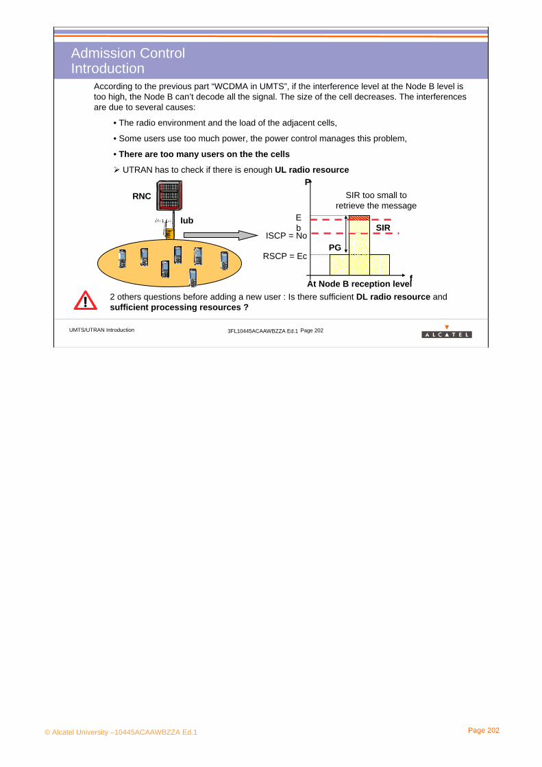
© Alcatel University –10445ACAAWBZZA Ed.1 Page 202
UMTS/UTRAN Introduction 3FL10445ACAAWBZZA Ed.1 Page 202
Admission ControlIntroduction
According to the previous part “WCDMA in UMTS”, if the interference level at the Node B level is too high, the Node B can’t decode all the signal. The size of the cell decreases. The interferences are due to several causes:
• The radio environment and the load of the adjacent cells,
• Some users use too much power, the power control manages this problem,
• There are too many users on the the cells
UTRAN has to check if there is enough UL radio resource
Iub
RNC
f
P
ISCP = NoSIR
PG
Eb
RSCP = Ec
At Node B reception level
SIR too small to retrieve the message
2 others questions before adding a new user : Is there sufficient DL radio resource andsufficient processing resources ?

© Alcatel University –10445ACAAWBZZA Ed.1 Page 203
UMTS/UTRAN Introduction 3FL10445ACAAWBZZA Ed.1 Page 203
Admission ControlPrinciples
Is there sufficient UL Radio Resource -> Rx RAC
If UL interference level + estimated new user contribution < threshold
Then Rx RAC ok
Is there sufficient DL Radio Resource -> Tx RAC
If Total DL Tx Power + estimated new user contribution < threshold
Then Tx RAC ok
Is there sufficient processing resource -> Processing RAC
3 main points are checked:
• the channelization codes
• The BB board capacities limited 1702.3 kbps
•The DSP (in BBs) load
•The number of user and radio links limited respectively to 64 users and 90 RLs
RAC = Radio Access Control

© Alcatel University –10445ACAAWBZZA Ed.1 Page 204
5. UTRAN Working
5.3 RAB Establishment5.3.2 Radio Bearers Establishment

© Alcatel University –10445ACAAWBZZA Ed.1 Page 205
UMTS/UTRAN Introduction 3FL10445ACAAWBZZA Ed.1 Page 205
Radio Bearers EstablishmentIntroduction
Signaling
Core NetworkIub
Node B
RNC
UTRAN
RAB
Radio Bearer Iu Bearer
Logical Channel
RLC
Transport Channel
MAC
Physical Channel
Phy.
RLC Mode: Tr., UM or AM and retranmission parameter for AM
TTI, TFS, TFCS, CRC, FEC, Coding Rate, Rate Matching
Frequency, Power, Channelization & Scrambling codes
RRC
Configured by
We have seen how a UE, after the switch on, can collect system information, update its location, request a RRC Connection and a service, can be paged and how UTRAN allows it to use services. Now how are established the RAB ?
RAC = Radio Access Control
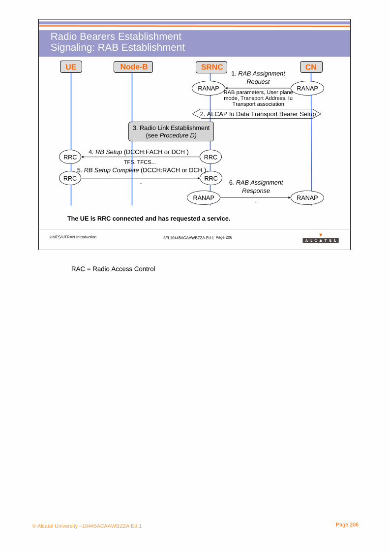
© Alcatel University –10445ACAAWBZZA Ed.1 Page 206
UMTS/UTRAN Introduction 3FL10445ACAAWBZZA Ed.1 Page 206
Radio Bearers EstablishmentSignaling: RAB Establishment
RANAP RANAP
1. RAB Assignment Request
RAB parameters, User plane mode, Transport Address, Iu
Transport association
2. ALCAP Iu Data Transport Bearer Setup
3. Radio Link Establishment(see Procedure D)
RRC RRC4. RB Setup (DCCH:FACH or DCH )
TFS, TFCS...
RRC RRC5. RB Setup Complete (DCCH:RACH or DCH )
-
RANAP RANAP
6. RAB Assignment Response
-
UE Node-B SRNC CN
The UE is RRC connected and has requested a service.
RAC = Radio Access Control

© Alcatel University –10445ACAAWBZZA Ed.1 Page 207
UMTS/UTRAN Introduction 3FL10445ACAAWBZZA Ed.1 Page 207
Radio Bearers Establishment Signaling: RL Setup
Cell id, TFS, TFCS, frequency, UL scrambling code, power control info
Radio Link Setup RequestNBAP NBAP
Signalling link termination, transport layer addressing info
Radio Link Setup ResponseNBAP NBAP
Downlink synchronisationIub-FP Iub-FP
Uplink synchronisationIub-FP Iub-FP
Start RX
Start TX
>> Are NBAP, ALCAP and RRC messages carried on the same transpor>> Are NBAP, ALCAP and RRC messages carried on the same transport bearers ont bearers on IubIub??
Node-B SRNC
ALCAP Iub Data Transport Bearer Setup
RAC = Radio Access Control•This procedure is used in many RRC procedures, e.g RRC connection
establishment (Procedure C1), Radio Bearer Set-up (Procedure F1), soft HO (Procedure G)…
• In this procedure:
a radio link is set up by the RNC on the Node-B side using the NBAP protocol
(a similar task is performed on the UE side using RRC protocol, see e.g. procedure C1)
a terrestrial link (AAL2 bearer) is setup on Iub interface using ALCAP protocol
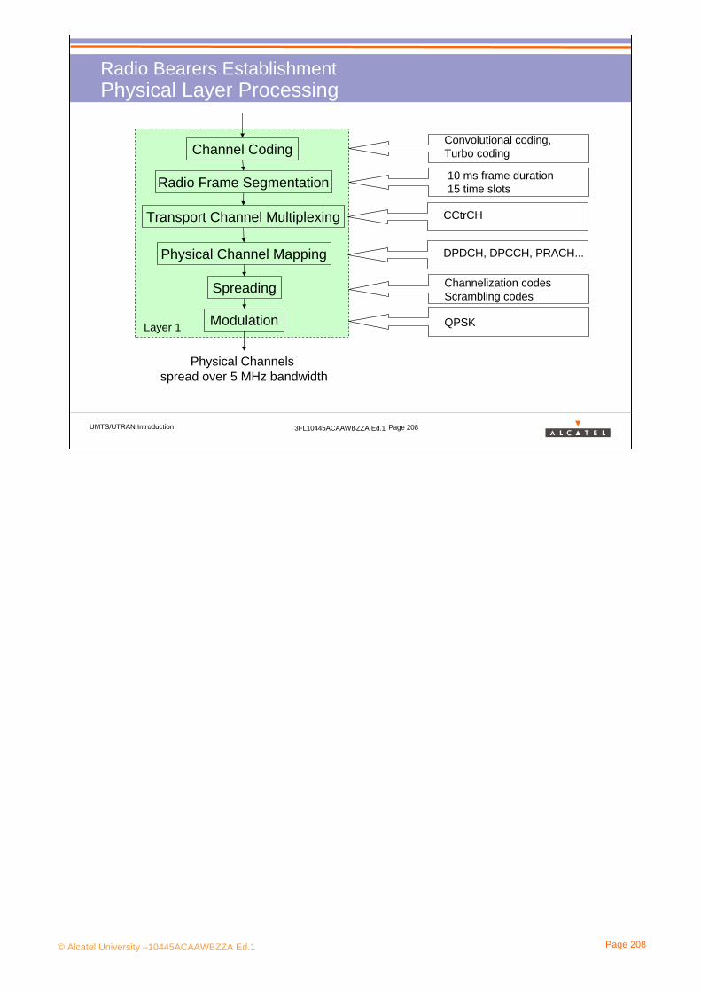
© Alcatel University –10445ACAAWBZZA Ed.1 Page 208
UMTS/UTRAN Introduction 3FL10445ACAAWBZZA Ed.1 Page 208
Radio Bearers EstablishmentPhysical Layer Processing
Convolutional coding, Turbo coding
10 ms frame duration15 time slots
CCtrCH
DPDCH, DPCCH, PRACH...
Channelization codesScrambling codes
QPSK
Channel Coding
Radio Frame Segmentation
Transport Channel Multiplexing
Physical Channel Mapping
Spreading
Modulation
Physical Channels spread over 5 MHz bandwidth
Layer 1
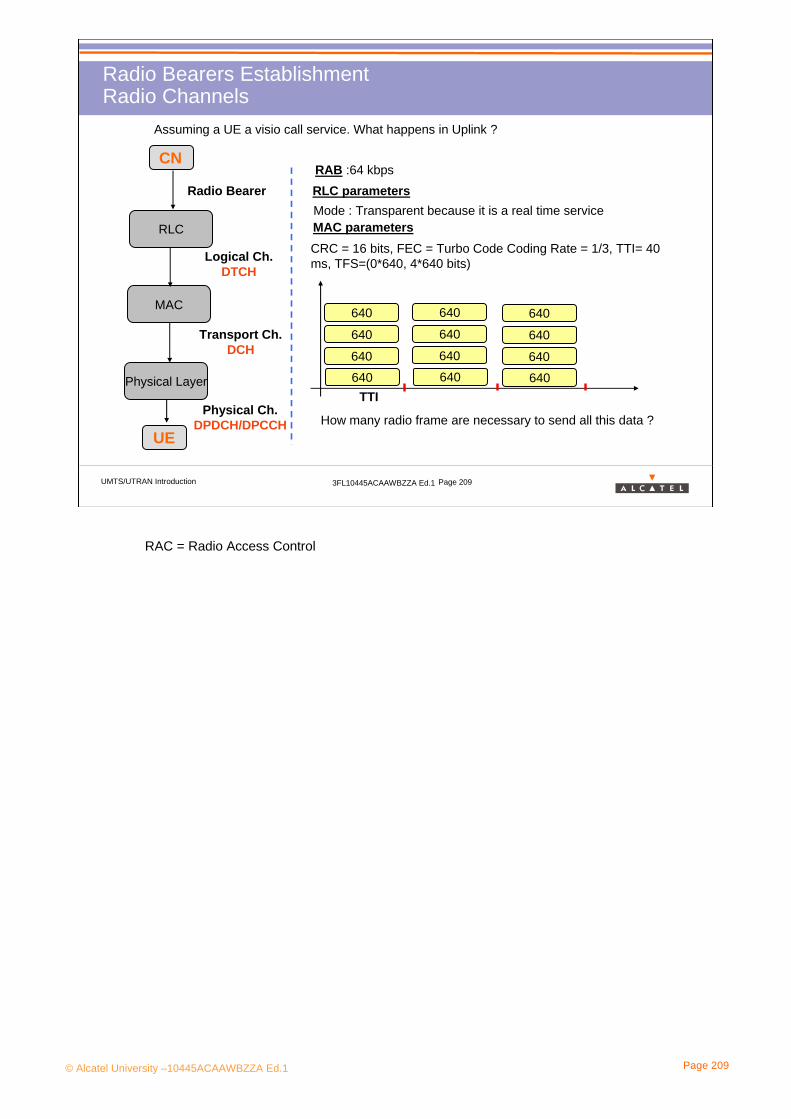
© Alcatel University –10445ACAAWBZZA Ed.1 Page 209
UMTS/UTRAN Introduction 3FL10445ACAAWBZZA Ed.1 Page 209
Radio Bearers Establishment Radio Channels
Assuming a UE a visio call service. What happens in Uplink ?
RLC
MAC
Physical Layer
Radio Bearer
Logical Ch. DTCH
Transport Ch. DCH
Physical Ch. DPDCH/DPCCH
UE
CN
RLC parametersRAB :64 kbps
MAC parametersMode : Transparent because it is a real time service
CRC = 16 bits, FEC = Turbo Code Coding Rate = 1/3, TTI= 40 ms, TFS=(0*640, 4*640 bits)
640
640
640
640
640
640
640
640
640
640
640
640
TTI
How many radio frame are necessary to send all this data ?
RAC = Radio Access Control

© Alcatel University –10445ACAAWBZZA Ed.1 Page 210
UMTS/UTRAN Introduction 3FL10445ACAAWBZZA Ed.1 Page 210
Radio Bearers Establishment Radio Channels: Data Processing
Assuming a UE a visio call service. What happens in Uplink ?
#1 #4…#1 #4…
Transport Blocks
CRC attachment
Tr Bl concatenation
Turbo coding (1/3)
Tail Bit Attachment
1 st interleaving
Radio Frame Segmentation
Rate matching
640 bits 16
(640+16)*4=2624 bits
2624*3=7872 bits
2624*3=7872 bits12
7884 bits
#1 #4…1971 1971
#1 #4…1971 +Nrm 1971 +Nrm
Can you deduce the SF ?
And the value of Nrm ?
RAC = Radio Access Control

© Alcatel University –10445ACAAWBZZA Ed.1 Page 211
UMTS/UTRAN Introduction 3FL10445ACAAWBZZA Ed.1 Page 211
Radio BearersEstablishment Radio Channels: Transport Channel Multiplexing
Assuming a UE a visio call service and on the same time sends on a e-mail.
How can it be possible to send 2 different services on the same physical channel ?
Several transport channels can be time-coordinated to be multiplexed on a CCTrCHbefore mapping on one physical channel
MAC
TFC Selection
L1
TrCH Multiplexing
Phy. Ch. Mapping
CCTrCH
Physical Channel
DCH1 DCH2
Example:
TFS (DCH1)={(0*640); (4*640)}
TFS(DCH2)={(1*0); (1*39); (1*42); (1*55); (1*65)}
TFCS={(0*640); (1*0)}; {(0*640); (1*39)}; {(0*640); (1*42)}; {(0*640); (1*55)}; {(0*640); (1*65)}; {(1*640); (1*39)}; {(1*640); (1*42)}
MAC selects TFC inside TFCS.
There is one TFCS per CCTrCH
Transport Format
Transport Format Combination
TFS= Transport Format SetTFCS=Transport Format Combination SetTF=Transport Format

© Alcatel University –10445ACAAWBZZA Ed.1 Page 212
UMTS/UTRAN Introduction 3FL10445ACAAWBZZA Ed.1 Page 212
Radio Bearers Establishment Radio Channels: DPDCH & DPCCH
Uplink
Downlink
Slot #0 Slot #1 Slot #13 Slot #14Slot #i
Slot #0 Slot #1 Slot #13 Slot #14Slot #i
Data : user data, RRC Signaling & NAS Signaling DPDCH
DPCCH Pilot TFCI FBI TPC
Multiplexed by the modulation
Data1 TPC Data2 TFCI Pilot
DPDCH DPCCH DPDCH DPCCH DPCCH
Time-multiplexed

© Alcatel University –10445ACAAWBZZA Ed.1 Page 213
5. UTRAN Scenario
5.4 Mobility Management in connected mode

© Alcatel University –10445ACAAWBZZA Ed.1 Page 214
UMTS/UTRAN Introduction 3FL10445ACAAWBZZA Ed.1 Page 214
Mobility Management in connected modeContent
> Program:
5.3.1 Soft Handover5.3.2 Compressed Mode 5.3.3 Hard Handover5.3.4 Inter RAT Handover

© Alcatel University –10445ACAAWBZZA Ed.1 Page 215
5. UTRAN Scenario
Soft Handover

© Alcatel University –10445ACAAWBZZA Ed.1 Page 216
UMTS/UTRAN Introduction 3FL10445ACAAWBZZA Ed.1 Page 216
Soft HandoverActive & Monitoring Set
Iub
RNC
Cell in the Active Set
Cell in the Monitoring Set
The RNC manages the Active Set and builds the Monitoring Set.
The Monitorin Set is built from the information of topology and design in the RNC.
The Active Set is managed from the event send by the UE to the RNC.
The maximum number of cells in the monitoring set is 32.The maximum number of cells in the active set is set from the Office Data, between 3 and 6.
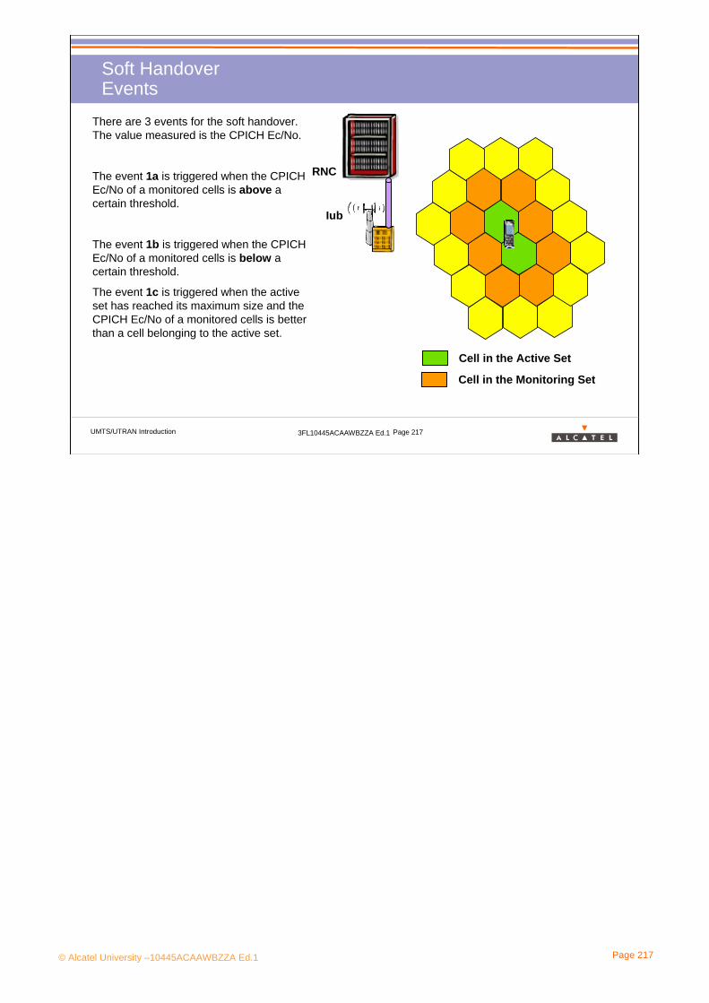
© Alcatel University –10445ACAAWBZZA Ed.1 Page 217
UMTS/UTRAN Introduction 3FL10445ACAAWBZZA Ed.1 Page 217
Soft HandoverEvents
Iub
RNC
Cell in the Active Set
Cell in the Monitoring Set
There are 3 events for the soft handover. The value measured is the CPICH Ec/No.
The event 1a is triggered when the CPICH Ec/No of a monitored cells is above a certain threshold.
The event 1b is triggered when the CPICHEc/No of a monitored cells is below a certain threshold.
The event 1c is triggered when the active set has reached its maximum size and the CPICH Ec/No of a monitored cells is better than a cell belonging to the active set.

© Alcatel University –10445ACAAWBZZA Ed.1 Page 218
UMTS/UTRAN Introduction 3FL10445ACAAWBZZA Ed.1 Page 218
Compressed Mode
Iub
RNC
Cell in the Active Set
Cell in the Monitoring Set, same FDD frequency
Cell in the Monitoring Set, other FDD frequency
Cell in the Monitoring Set, GSM cell
The most of the UE are not dual receiver. And they need to perform measurement an other frequencies.
So UTRAN has to free it some time to perform these measurements on other FDD frequencies or on GSM frequencies.
The main method is to divide the SF of certain frame by 2, so it divides the length of the frame by 2.
Time interval to measure other frequencies

© Alcatel University –10445ACAAWBZZA Ed.1 Page 219
UMTS/UTRAN Introduction 3FL10445ACAAWBZZA Ed.1 Page 219
Hard Handover on other FDD FrequenciesEvents
Iub
RNC
Cell in the Active Set
Cell in the Monitoring Set, same FDD frequency
Cell in the Monitoring Set, other FDD frequency
Cell in the Monitoring Set, GSM cell
There are 4 events to watch the UMTS cell with other FDD frequencies
The event 2d_cm is triggered when the quality of on the current frequency is below a certain quality. The compressed mode is launched.
The event 2b is triggered when the quality of the current frequency is below a certain threshold and the quality on an other frequency is above a certain threshold
The event 2f is triggered when the quality on the current frequency is above a certain threshold. The compressed mode is desactivited.

© Alcatel University –10445ACAAWBZZA Ed.1 Page 220
UMTS/UTRAN Introduction 3FL10445ACAAWBZZA Ed.1 Page 220
Hard Handover on other GSM FrequenciesEvents
Iub
RNC
Cell in the Active Set
Cell in the Monitoring Set, same FDD frequency
Cell in the Monitoring Set, other FDD frequency
Cell in the Monitoring Set, GSM cell
2 causes can trigger an hard HO toward the GSM system:
• Some bad radio conditions
• due to the service requested
The event 2d_cm is triggered when the quality of on the current frequency is below a certain quality. The compressed mode is launched.
The event 3a is triggered when the quality on the current FDD frequency is below a certain threshold and the quality on the GSM is above another threshold.
The event 3c is triggered when the service requested can be managed by the GSM, the voice typically.

© Alcatel University –10445ACAAWBZZA Ed.1 Page 221
UMTS/UTRAN Introduction 3FL10445ACAAWBZZA Ed.1 Page 221
Exercise 1/3
Objectives: Rebuilt the channels mapping, Logical, Transport and Physical, from a scenario to guide you with the 2 next pages
Scenario:
• The UE switches on in a covered area.
•The UE collects information about the system
•The UE request a RRC connection to declare its location and releases the RRC connection
•The UE receives a paging message to receive an e-mail.
•UTRAN establishes a RAB and is in the DCH_Cell State
•Like the traffic is not large, the UE pass to the FACH_Cell State.
Be careful, following this scenario, some channels are missing. Which are the missing channels ?

© Alcatel University –10445ACAAWBZZA Ed.1 Page 222
UMTS/UTRAN Introduction 3FL10445ACAAWBZZA Ed.1 Page 222
Exercise 2/3Downlink
Logical Ch
Transport Ch
Physical Ch

© Alcatel University –10445ACAAWBZZA Ed.1 Page 223
UMTS/UTRAN Introduction 3FL10445ACAAWBZZA Ed.1 Page 223
Exercise 3/3Uplink
Logical Ch
Transport Ch
Physical Ch

© Alcatel University –10445ACAAWBZZA Ed.1 Page 224
Appendix

© Alcatel University –10445ACAAWBZZA Ed.1 Page 225
UMTS/UTRAN Introduction 3FL10445ACAAWBZZA Ed.1 Page 225
Appendix
• “Just after switch on” process
• AMR codec
•NBAP elementary procedures
•RANAP elementary procedures

© Alcatel University –10445ACAAWBZZA Ed.1 Page 226
UMTS/UTRAN Introduction 3FL10445ACAAWBZZA Ed.1 Page 226
PLMN selection
Cell selection
Attachment2
1 After switch on, the UE:
- scans the entire frequency bandwidths of UTRAN FDD and GSM (cell search procedure for UTRAN FDD )
- monitors the broadcast channels (BCCH for UTRAN FDD) to get the PLMN identifiers.
Hence the UE can establish a list of PLMNs which are available in its location.
List of availablePLMNs
UE switche
d on
1
In the list of available PLMNs, the UE selects:
- the HPLMN (Home PLMN) if it is available
- otherwise another PLMN (national or international) according to priority rules possibly stored in the USIM
Selected PLMN2
“Just after switch on” processPLMN Selection
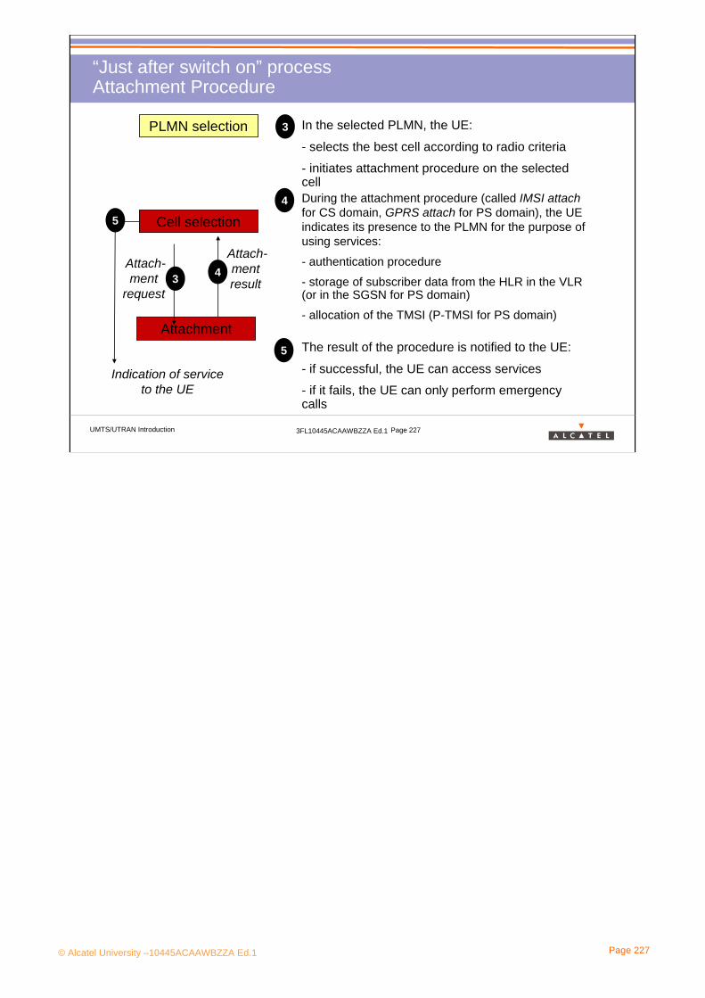
© Alcatel University –10445ACAAWBZZA Ed.1 Page 227
UMTS/UTRAN Introduction 3FL10445ACAAWBZZA Ed.1 Page 227
“Just after switch on” processAttachment Procedure
PLMN selection
Cell selection
Attachment
3
4
In the selected PLMN, the UE:
- selects the best cell according to radio criteria
- initiates attachment procedure on the selected cell
Attach-ment
request 3
During the attachment procedure (called IMSI attachfor CS domain, GPRS attach for PS domain), the UE indicates its presence to the PLMN for the purpose of using services:
- authentication procedure
- storage of subscriber data from the HLR in the VLR (or in the SGSN for PS domain)
- allocation of the TMSI (P-TMSI for PS domain)
Attach-mentresult
4
5
Indication of service to the UE
The result of the procedure is notified to the UE:
- if successful, the UE can access services
- if it fails, the UE can only perform emergency calls
5

© Alcatel University –10445ACAAWBZZA Ed.1 Page 228
UMTS/UTRAN Introduction 3FL10445ACAAWBZZA Ed.1 Page 228
AppendixAMR codecs
The AMR (Adaptative Multirate) speech codec:- offers 8 AMR modes between 4,75 kbits/s and 12,2 kbits/s- is capable of switching its bit rate every 20 ms upon command of the RNC- is located in the UE and in the transcoder (which is located in the CN)
AMR mode Source coding bit-rate ClassA
ClassB
ClassC
AMR_12.20 12.20 kbit/s (GSM EFR) 81 103 60AMR_10.20 10.20 kbit/s 65 99 40AMR_7.95 7.95 kbit/s 75 84 0AMR_7.40 7.40 kbit/s (IS-641) 61 87 0AMR_6.70 6.70 kbit/s (PDC-EFR) 58 76 0AMR_5.90 5.90 kbit/s 55 63 0AMR_5.15 5.15 kbit/s 49 54 0AMR_4.75 4.75 kbit/s 42 53 0
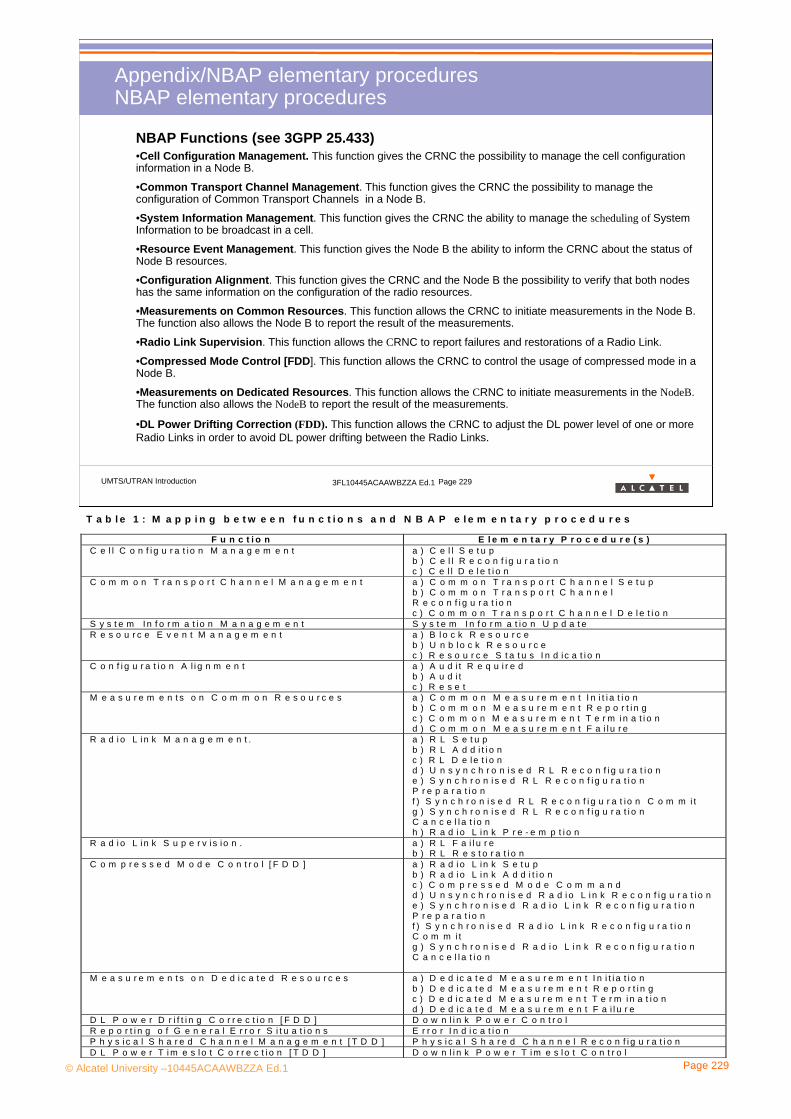
© Alcatel University –10445ACAAWBZZA Ed.1 Page 229
UMTS/UTRAN Introduction 3FL10445ACAAWBZZA Ed.1 Page 229
Appendix/NBAP elementary procedures NBAP elementary procedures
•Cell Configuration Management. This function gives the CRNC the possibility to manage the cell configuration information in a Node B.
•Common Transport Channel Management. This function gives the CRNC the possibility to manage the configuration of Common Transport Channels in a Node B.
•System Information Management. This function gives the CRNC the ability to manage the scheduling of System Information to be broadcast in a cell.
•Resource Event Management. This function gives the Node B the ability to inform the CRNC about the status of Node B resources.
•Configuration Alignment. This function gives the CRNC and the Node B the possibility to verify that both nodes has the same information on the configuration of the radio resources.
•Measurements on Common Resources. This function allows the CRNC to initiate measurements in the Node B. The function also allows the Node B to report the result of the measurements.
•Radio Link Supervision. This function allows the CRNC to report failures and restorations of a Radio Link.
•Compressed Mode Control [FDD]. This function allows the CRNC to control the usage of compressed mode in a Node B.
•Measurements on Dedicated Resources. This function allows the CRNC to initiate measurements in the NodeB. The function also allows the NodeB to report the result of the measurements.
•DL Power Drifting Correction (FDD). This function allows the CRNC to adjust the DL power level of one or more Radio Links in order to avoid DL power drifting between the Radio Links.
NBAP Functions (see 3GPP 25.433)
T a b l e 1 : M a p p i n g b e t w e e n f u n c t i o n s a n d N B A P e l e m e n t a r y p r o c e d u r e s
F u n c t i o n E l e m e n t a r y P r o c e d u r e ( s )C e l l C o n f i g u r a t io n M a n a g e m e n t a ) C e l l S e t u p
b ) C e l l R e c o n f i g u r a t io nc ) C e l l D e l e t i o n
C o m m o n T r a n s p o r t C h a n n e l M a n a g e m e n t a ) C o m m o n T r a n s p o r t C h a n n e l S e t u pb ) C o m m o n T r a n s p o r t C h a n n e lR e c o n f i g u r a t i o nc ) C o m m o n T r a n s p o r t C h a n n e l D e l e t i o n
S y s t e m I n f o r m a t io n M a n a g e m e n t S y s t e m I n f o r m a t io n U p d a t eR e s o u r c e E v e n t M a n a g e m e n t a ) B l o c k R e s o u r c e
b ) U n b l o c k R e s o u r c ec ) R e s o u r c e S t a t u s I n d ic a t i o n
C o n f i g u r a t io n A l i g n m e n t a ) A u d i t R e q u i r e db ) A u d i tc ) R e s e t
M e a s u r e m e n t s o n C o m m o n R e s o u r c e s a ) C o m m o n M e a s u r e m e n t I n i t i a t i o nb ) C o m m o n M e a s u r e m e n t R e p o r t i n gc ) C o m m o n M e a s u r e m e n t T e r m i n a t i o nd ) C o m m o n M e a s u r e m e n t F a i l u r e
R a d i o L i n k M a n a g e m e n t . a ) R L S e t u pb ) R L A d d i t i o nc ) R L D e le t i o nd ) U n s y n c h r o n i s e d R L R e c o n f i g u r a t i o ne ) S y n c h r o n i s e d R L R e c o n f i g u r a t i o nP r e p a r a t i o nf ) S y n c h r o n i s e d R L R e c o n f i g u r a t io n C o m m i tg ) S y n c h r o n i s e d R L R e c o n f i g u r a t i o nC a n c e l l a t i o nh ) R a d i o L in k P r e - e m p t i o n
R a d i o L i n k S u p e r v i s io n . a ) R L F a i l u r eb ) R L R e s t o r a t i o n
C o m p r e s s e d M o d e C o n t r o l [ F D D ] a ) R a d i o L in k S e t u pb ) R a d i o L in k A d d i t i o nc ) C o m p r e s s e d M o d e C o m m a n dd ) U n s y n c h r o n i s e d R a d i o L i n k R e c o n f ig u r a t i o ne ) S y n c h r o n i s e d R a d i o L i n k R e c o n f i g u r a t i o nP r e p a r a t i o nf ) S y n c h r o n i s e d R a d i o L i n k R e c o n f ig u r a t i o nC o m m i tg ) S y n c h r o n i s e d R a d i o L i n k R e c o n f i g u r a t i o nC a n c e l l a t i o n
M e a s u r e m e n t s o n D e d i c a t e d R e s o u r c e s a ) D e d ic a t e d M e a s u r e m e n t I n i t i a t i o nb ) D e d ic a t e d M e a s u r e m e n t R e p o r t i n gc ) D e d ic a t e d M e a s u r e m e n t T e r m i n a t i o nd ) D e d ic a t e d M e a s u r e m e n t F a i l u r e
D L P o w e r D r i f t i n g C o r r e c t i o n [ F D D ] D o w n l i n k P o w e r C o n t r o lR e p o r t i n g o f G e n e r a l E r r o r S i t u a t i o n s E r r o r I n d i c a t i o nP h y s i c a l S h a r e d C h a n n e l M a n a g e m e n t [ T D D ] P h y s i c a l S h a r e d C h a n n e l R e c o n f i g u r a t i o nD L P o w e r T i m e s l o t C o r r e c t i o n [ T D D ] D o w n l i n k P o w e r T i m e s l o t C o n t r o l
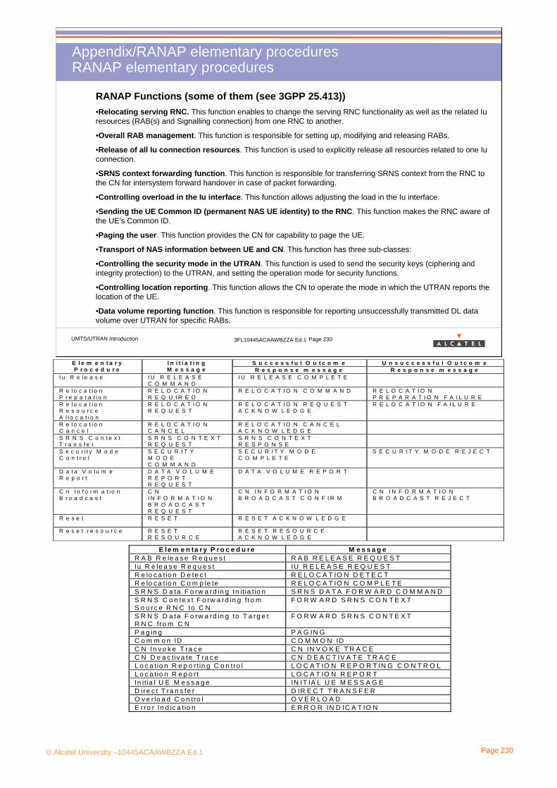
© Alcatel University –10445ACAAWBZZA Ed.1 Page 230
UMTS/UTRAN Introduction 3FL10445ACAAWBZZA Ed.1 Page 230
Appendix/RANAP elementary procedures RANAP elementary procedures
•Relocating serving RNC. This function enables to change the serving RNC functionality as well as the related Iuresources (RAB(s) and Signalling connection) from one RNC to another.
•Overall RAB management. This function is responsible for setting up, modifying and releasing RABs.
•Release of all Iu connection resources. This function is used to explicitly release all resources related to one Iuconnection.
•SRNS context forwarding function. This function is responsible for transferring SRNS context from the RNC to the CN for intersystem forward handover in case of packet forwarding.
•Controlling overload in the Iu interface. This function allows adjusting the load in the Iu interface.
•Sending the UE Common ID (permanent NAS UE identity) to the RNC. This function makes the RNC aware of the UE's Common ID.
•Paging the user. This function provides the CN for capability to page the UE.
•Transport of NAS information between UE and CN. This function has three sub-classes:
•Controlling the security mode in the UTRAN. This function is used to send the security keys (ciphering andintegrity protection) to the UTRAN, and setting the operation mode for security functions.
•Controlling location reporting. This function allows the CN to operate the mode in which the UTRAN reports the location of the UE.
•Data volume reporting function. This function is responsible for reporting unsuccessfully transmitted DL data volume over UTRAN for specific RABs.
RANAP Functions (some of them (see 3GPP 25.413))
S u c c e s s f u l O u t c o m e U n s u c c e s s f u l O u t c o m eE l e m e n t a r yP r o c e d u r e
I n i t i a t i n gM e s s a g e R e s p o n s e m e s s a g e R e s p o n s e m e s s a g e
I u R e l e a s e I U R E L E A S EC O M M A N D
I U R E L E A S E C O M P L E T E
R e l o c a t i o nP r e p a r a t i o n
R E L O C A T I O NR E Q U I R E D
R E L O C A T I O N C O M M A N D R E L O C A T I O NP R E P A R A T I O N F A I L U R E
R e l o c a t i o nR e s o u r c eA l l o c a t i o n
R E L O C A T I O NR E Q U E S T
R E L O C A T I O N R E Q U E S TA C K N O W L E D G E
R E L O C A T I O N F A I L U R E
R e l o c a t i o nC a n c e l
R E L O C A T I O NC A N C E L
R E L O C A T I O N C A N C E LA C K N O W L E D G E
S R N S C o n t e x tT r a n s f e r
S R N S C O N T E X TR E Q U E S T
S R N S C O N T E X TR E S P O N S E
S e c u r i t y M o d eC o n t r o l
S E C U R I T YM O D EC O M M A N D
S E C U R I T Y M O D EC O M P L E T E
S E C U R I T Y M O D E R E J E C T
D a t a V o lu m eR e p o r t
D A T A V O L U M ER E P O R TR E Q U E S T
D A T A V O L U M E R E P O R T
C n I n f o r m a t i o nB r o a d c a s t
C NI N F O R M A T I O NB R O A D C A S TR E Q U E S T
C N I N F O R M A T I O NB R O A D C A S T C O N F I R M
C N I N F O R M A T I O NB R O A D C A S T R E J E C T
R e s e t R E S E T R E S E T A C K N O W L E D G E
R e s e t r e s o u r c e R E S E TR E S O U R C E
R E S E T R E S O U R C EA C K N O W L E D G E
E le m e n ta r y P ro c e d u re M e s s a g eR A B R e le a s e R e q u e s t R A B R E L E A S E R E Q U E S TIu R e le a s e R e q u e s t IU R E L E A S E R E Q U E S TR e lo c a t io n D e te c t R E L O C A T IO N D E T E C TR e lo c a t io n C o m p le te R E L O C A T IO N C O M P L E T ES R N S D a ta F o rw a rd in g In it ia tio n S R N S D A T A F O R W A R D C O M M A N DS R N S C o n te x t F o rw a rd in g fro mS o u rc e R N C to C N
F O R W A R D S R N S C O N T E X T
S R N S D a ta F o rw a rd in g to T a rg e tR N C fro m C N
F O R W A R D S R N S C O N T E X T
P a g in g P A G IN GC o m m o n ID C O M M O N IDC N In v o k e T ra c e C N IN V O K E T R A C EC N D e a c t iv a te T ra c e C N D E A C T IV A T E T R A C EL o c a tio n R e p o r tin g C o n tro l L O C A T IO N R E P O R T IN G C O N T R O LL o c a tio n R e p o r t L O C A T IO N R E P O R TIn it ia l U E M e s s a g e IN IT IA L U E M E S S A G ED ire c t T ra n s fe r D IR E C T T R A N S F E RO v e r lo a d C o n tro l O V E R L O A DE rro r In d ic a tio n E R R O R IN D IC A T IO N

© Alcatel University –10445ACAAWBZZA Ed.1 Page 231
UMTS/UTRAN Introduction 3FL10445ACAAWBZZA Ed.1 Page 231
Appendix/RSNAP elementary procedures RSNAP elementary procedures
•Radio Link Management. This function allows the SRNC to manage radio links using dedicated resources in a DRNS;
•Physical Channel Reconfiguration. This function allows the DRNC to reallocate the physical channel resources for a Radio Link;
•Radio Link Supervision. This function allows the DRNC to report failures and restorations of a Radio Link;
•Compressed Mode Control [FDD]. This function allows the SRNC to control the usage of compressed mode within a DRNS;
•Measurements on Dedicated Resources. This function allows the SRNC to initiate measurements on dedicated resources in the DRNS. The function also allows the DRNC to report the result of the measurements;
•DL Power Drifting Correction [FDD]. This function allows the SRNC to adjust the DL power level of one or more Radio Links in order to avoid DL power drifting between the Radio Links;
•CCCH Signalling Transfer. This function allows the SRNC and DRNC to pass information between the UE and the SRNC on a CCCH controlled by the DRNS;
•Paging. This function allows the SRNC to page a UE in a URA or a cell in the DRNS;
•Common Transport Channel Resources Management. This function allows the SRNC to utilise Common Transport Channel Resources within the DRNS (excluding DSCH resources for FDD);
•Relocation Execution. This function allows the SRNC to finalise a Relocation previously prepared via other interfaces.
RSNAP Functions (some of them (see 3GPP 25.423))
Fun ct ion Ele m e n t a ry Proce du re ( s) Radio Link Managem ent a) Radio Link Setup
b) Radio Link Addit ion c) Radio Link Delet ion d) Unsynchronised Radio Link Reconfigurat ion e) Synchronised Radio Link Reconfigurat ion Preparat ion f) Synchronised Radio Link Reconfigurat ion Com m it g) Synchronised Radio Link Reconfigurat ion Cancellat ion
Physical Channel Reconfigurat ion Physical Channel Reconfigurat ion Radio Link Supervision a) Radio Link Failure
b) Radio Link Restorat ion Com pressed Mode Control [ FDD] a) Radio Link Setup
b) Radio Link Addit ion c) Com pressed Mode Com m and d) Unsynchronised Radio Link Reconfigurat ion e) Synchronised Radio Link Reconfigurat ion Preparat ion f) Synchronised Radio Link Reconfigurat ion Com m it g) Synchronised Radio Link Reconfigurat ion Cancellat ion
Measurem ents on Dedicated Resources a) Measurem ent I nit iat ion b) Measurem ent Report ing c) Measurem ent Term inat ion d) Measurem ent Failure
DL Pow er Drif t ing Correct ion [ FDD] Dow nlink Pow er Control CCCH Signalling Transfer a) Uplink Signalling Transfer
b) Dow nlink Signalling Transfer Paging Paging Com m on Transport Channel Resources Managem ent
a) Com m on Transport Channel Resources I n it iat ion b) Com m on Transport Channel Resources Release
Relocat ion Execut ion Relocat ion Com m it Report ing of General Error Situat ions Error I ndicat ion

© Alcatel University –10445ACAAWBZZA Ed.1 Page 232
UMTS/UTRAN Introduction 3FL10445ACAAWBZZA Ed.1 Page 232
Related Documentation
Abbreviations and Acronyms

© Alcatel University –10445ACAAWBZZA Ed.1 Page 233
UMTS/UTRAN Introduction 3FL10445ACAAWBZZA Ed.1 Page 233
Related documentation
English- WCDMA for UMTS, Harri Holma and Antti Toskala, Wiley 2000, ISBN 0 471 72051 8
- UMTS Mobile communications for the future, Wiley 2001, ISBN 0 471 49829 7
- Alcatel Telecommunications Review, 1st Quarter 2001 (“Find your way with 3G”)
- 3GPP specifications: ftp://ftp.3gpp.org/Specs/ftp://ftp.3gpp.org/Specs/
Francais- UMTS les réseaux mobiles de troisième génération, Editions Eyrolles 2001 (translation of “WCDMA for UMTS” )
- UMTS les origines, l'architecture, la norme, Pierre Lescuyer, Editions Dunod 2001, ISBN 2 10 005195 4
- Revue des Télécommunications d’Alcatel , 1er trimestre 2001 (entièrement consacrée à la 3G)

© Alcatel University –10445ACAAWBZZA Ed.1 Page 234
UMTS/UTRAN Introduction 3FL10445ACAAWBZZA Ed.1 Page 234
Abbreviations and Acronyms (1)
AAL ATM Adaptation LayerACELP Algebraic Code Excited Linear PredictionADN Abbreviated Dialling NumberALCAP Access Link Control Application PartAMR Adaptive Multi RateATM Asynchronous Transfer ModeBCCH Broadcast Control ChannelBCH Broadcast ChannelBHCA Busy Hour Call AttemptsBER Bit Error RateBLER Block Error RateBMC Broadcast / Multicast ControlBM-IWF Broadcast Multicast InterWorking
FunctionBSC Base Station Controller BSS Base Station (sub)System BTS Base Transceiver Station CAMEL Customized Application for Mobile
Enhanced LogicCC Call Control
CCCH Common Control ChannelCCTrCH Coded Composite Transport ChannelCDMA Code Division Multiple AccessCDR Call Detail Record CN Core NetworkCPCH Common Packet ChannelCRNC Controlling RNCCS Circuit SwitchedCTCH Common Traffic ChannelDCA Dynamic channel AllocationDCCH Dedicated Control ChannelDCH Dedicated ChannelDHO Diversity HandOverDHT Diversity HandOver TrunkDRAC Dynamic Resource Allocation ControlDRNC Drift RNCDS Direct SequenceDSCH Downlink Shared ChannelDTCH Dedicated Traffic Channel

© Alcatel University –10445ACAAWBZZA Ed.1 Page 235
UMTS/UTRAN Introduction 3FL10445ACAAWBZZA Ed.1 Page 235
Abbreviations and Acronyms (2)
EDGE Enhanced Data rates for GSM EvolutionERAN EDGE Radio Access Network (all-IP)FACH Forward Access ChannelFBI FeedBack InformationFDD Frequency Division DuplexFDD-DS FDD-Direct Sequence (FDD1)FDD-MC FDD-Multiple Carrier (FDD2)FER Frame Error RateFP Frame ProtocolFTP File Transfer Protocol GERAN GSM/EDGE Radio Access NetworkGGSN Gateway GPRS Support NodeGPRS General Packet Radio ServiceGSM Global System for Mobile CommunicationsGSN GPRS Support Node (ie SGSN or GGSN)GTP GPRS Tunneling ProtocolGTP-U GPRS Tunneling Protocol-User PlaneHO HandOverHPLMN Home PLM
IETF Internet Engineering Task Force IMEI International Mobile Equipment IdentityIMSI International Mobile Subscriber IdentityIP Internet ProtocolIR Incremental RedundancyISDN Integrated Services Digital NetworkL1,L2,L3 Layer 1, Layer 2, Layer 3LA Location AreaLCS Location ServicesLLC Logical Link ControlLQC Link Quality ControlM3UA SS7 MTP3 User Adaptation layerMAC Medium Access ControlMBS Multi-standard Base StationMC Multiple CarrierMExE Mobile Execution EnvironmentMM Mobility Management MSC Mobile-services Switching CenterMSP Multiple Subscriber Profile
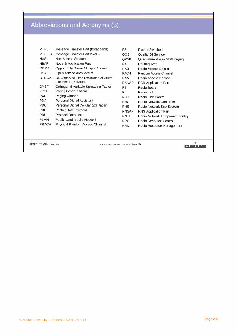
© Alcatel University –10445ACAAWBZZA Ed.1 Page 236
UMTS/UTRAN Introduction 3FL10445ACAAWBZZA Ed.1 Page 236
Abbreviations and Acronyms (3)
MTP3 Message Transfer Part (broadband)MTP-3B Message Transfer Part level 3NAS Non Access StratumNBAP Node-B Application PartODMA Opportunity Driven Multiple AccessOSA Open service ArchitectureOTDOA-IPDL Observed Time Difference of Arrival
Idle Period DownlinkOVSF Orthogonal Variable Spreading FactorPCCH Paging Control ChannelPCH Paging ChannelPDA Personal Digital AssistantPDC Personal Digital Cellular (2G Japan)PDP Packet Data ProtocolPDU Protocol Data UnitPLMN Public Land Mobile NetworkPRACH Physical Random Access Channel
PS Packet SwitchedQOS Quality Of Service QPSK Quadrature Phase Shift KeyingRA Routing AreaRAB Radio Access BearerRACH Random Access ChannelRAN Radio Access NetworkRANAP RAN Application PartRB Radio BearerRL Radio LinkRLC Radio Link ControlRNC Radio Network ControllerRNS Radio Network Sub-System RNSAP RNS Application PartRNTI Radio Network Temporary IdentityRRC Radio Resource ControlRRM Radio Resource Management
© Alcatel University –10445ACAAWBZZA Ed.1 Page 237
UMTS/UTRAN Introduction 3FL10445ACAAWBZZA Ed.1 Page 237
Abbreviations and Acronyms (4)
SAP Service Access PointSAT SIM Application ToolkitSDU Service Data UnitSF Spreading FactorSGSN Serving GPRS Support Node SHO Soft HandOverSIR Signal to Interference RatioSMS Short Message ServiceSPU Signaling Processing UnitSRNC Serving RNCSSCOP Service Specific Connection Oriented
ProtocolSSCP Signaling Connection Control PartSTM Synchronous Transfer ModeTC TranscoderTCP Transport Control ProtocolTD-CDMA Time Division & CDMATDD Time Division DuplexTDMA Time Division Multiple Access
TF Transport Format TFC Transport Format Combination TFCI Transport Format Combination IndicatorTFCS Transport Format Combination SetTFS Transport Format SetTMSI Temporary Mobile Station IdentityTPC Transmission Power ControlUDP User Datagram ProtocolUICC UMTS Integrated Circuit CardUMTS Universal Mobile Telecommunication
SystemUSIM UMTS Subscriber Identity Card USSD Unstructured Supplementary Service
DataURA UTRAN Registration AreaURAN UMTS Radio Access Network (ETSI)
Universal Radio Access Network (3GPP)USB Universal Serial BusUTRAN UMTS Terrestrial Radio Access Network
© Alcatel University –10445ACAAWBZZA Ed.1 Page 238
UMTS/UTRAN Introduction 3FL10445ACAAWBZZA Ed.1 Page 238
Abbreviations and Acronyms (5)
VC Virtual ChannelVHE Virtual Home EnvironmentVoIP Voice over IPVP Virtual PathWAP Wireless Application ProtocolW-CDMA Wideband Code Division Multiple
AccessWIM WAP Identity Module

© Alcatel University –10445ACAAWBZZA Ed.1 Page 239
UMTS/UTRAN Introduction 3FL10445ACAAWBZZA Ed.1 Page 239
Abbreviations and Acronyms (Standard Organizations)
3GPP 3rd Generation Partnership Project (WCDMA)3GPP2 3rd Generation Partnership Project 2 (cdma2000)3GIP 3rd Generation partnership for Internet Protocol ANSI American National Standard Institute (USA)ARIB Association of Radio Industries and Business (Japan)CWTS China Wireless Telecommunication Standard groupETSI European Telecommunication Standard InstituteIETF Internet Engineering Task ForceIMT International Mobile TelecommunicationITU International Telecommunication UnionT1 Committee T1 telecommunication of the ANSI (USA)TIA Telecommunication Industry Association (USA)TTA Telecommunication Technology Association (Korea)TTC Telecommunication Technology Committee (Japan)UWCC Universal Wireless Communications CommitteeW3C World Wide Web Consortium