um1549 user manual - stmicroelectronics · and widgets, and memory management. the stm32...
TRANSCRIPT

August 2012 Doc ID 023269 Rev 1 1/47
UM1549User manual
STM32 Demonstration Builder
IntroductionThe STM32 family of 32-bit Flash microcontrollers based on the ARM Cortex™ M processor is designed to offer new degrees of freedom to MCU users. It offers a 32-bit product range that combines high performance, real-time capabilities, digital signal processing, and low-power, low-voltage operation, while maintaining full integration and ease of development.
The unparalleled and large range of STM32 devices, based on an industry-standard core and accompanied by a vast choice of tools and software, makes this family of products the ideal choice, both for small projects and for entire platform decisions.
The STM32 Demonstration Builder platform is a completely new way to deliver a demonstration that can also be fully or partially reused in real applications. It relies on a full set of software components, coming in flexible licensing schemes allowing easy reuse and redistribution. All these components are organized within a module architecture that allows them to be reused separately in standalone applications.
The versatility of the STM32 Demonstration Builder platform allows the dynamic addition of modules, granting access to common resources, including storage, graphical components and widgets, and memory management.
The STM32 Demonstration Builder platform is built around the STM32 graphical library and the FreeRTOS real-time operating system, and uses almost the entire STM32 capability to offer a large scope of usage.
This Demonstration supports STM32F2xx and STM32F4xx devices and runs on STM3220G-EVAL and STM3240G-EVAL evaluation boards from STMicroelectronics.
This document describes the usage of the demonstration and the different included modules. For more details about the demonstration builder architecture, please refer to the UM1550.
Table 1. Applicable tools
Type Part numbers
Evaluation tools STM3220G-EVAL,STM3240G-EVAL
www.st.com
Contents UM1549
2/47 Doc ID 023269 Rev 1
Contents
1 STM32 Demonstration Builder applications and features . . . . . . . . . . . 7
2 Development platform overview . . . . . . . . . . . . . . . . . . . . . . . . . . . . . . . 8
2.1 Hardware resources . . . . . . . . . . . . . . . . . . . . . . . . . . . . . . . . . . . . . . . . . . 8
2.2 Software resources . . . . . . . . . . . . . . . . . . . . . . . . . . . . . . . . . . . . . . . . . . 9
2.3 Firmware architecture . . . . . . . . . . . . . . . . . . . . . . . . . . . . . . . . . . . . . . . 10
3 Description of the demonstration startup process . . . . . . . . . . . . . . . 12
3.1 Startup window . . . . . . . . . . . . . . . . . . . . . . . . . . . . . . . . . . . . . . . . . . . . . 12
3.2 Main menu windows . . . . . . . . . . . . . . . . . . . . . . . . . . . . . . . . . . . . . . . . . 13
3.2.1 Connectivity group window . . . . . . . . . . . . . . . . . . . . . . . . . . . . . . . . . . 13
3.2.2 Multimedia group window . . . . . . . . . . . . . . . . . . . . . . . . . . . . . . . . . . . 14
3.2.3 Utilities group window . . . . . . . . . . . . . . . . . . . . . . . . . . . . . . . . . . . . . . 14
4 Description of Utilities group applications . . . . . . . . . . . . . . . . . . . . . . 16
4.1 System module . . . . . . . . . . . . . . . . . . . . . . . . . . . . . . . . . . . . . . . . . . . . . 16
4.2 Calendar module . . . . . . . . . . . . . . . . . . . . . . . . . . . . . . . . . . . . . . . . . . . 18
4.3 File manager module . . . . . . . . . . . . . . . . . . . . . . . . . . . . . . . . . . . . . . . . 19
4.4 Log module . . . . . . . . . . . . . . . . . . . . . . . . . . . . . . . . . . . . . . . . . . . . . . . 22
4.5 Credits module . . . . . . . . . . . . . . . . . . . . . . . . . . . . . . . . . . . . . . . . . . . . . 22
5 Description of Multimedia group applications . . . . . . . . . . . . . . . . . . . 23
5.1 Audio player module . . . . . . . . . . . . . . . . . . . . . . . . . . . . . . . . . . . . . . . . . 23
5.1.1 Audio player module features . . . . . . . . . . . . . . . . . . . . . . . . . . . . . . . . 26
5.1.2 Supported audio formats . . . . . . . . . . . . . . . . . . . . . . . . . . . . . . . . . . . . 26
5.2 Audio recorder module . . . . . . . . . . . . . . . . . . . . . . . . . . . . . . . . . . . . . . . 26
5.3 Image browser module . . . . . . . . . . . . . . . . . . . . . . . . . . . . . . . . . . . . . . . 27
5.4 Camera module . . . . . . . . . . . . . . . . . . . . . . . . . . . . . . . . . . . . . . . . . . . . 31
6 Description of Connectivity group applications . . . . . . . . . . . . . . . . . 34
6.1 Ethernet module . . . . . . . . . . . . . . . . . . . . . . . . . . . . . . . . . . . . . . . . . . . . 34
6.1.1 Using the webserver application . . . . . . . . . . . . . . . . . . . . . . . . . . . . . . 36
6.1.2 Webserver functions . . . . . . . . . . . . . . . . . . . . . . . . . . . . . . . . . . . . . . . 37
UM1549 Contents
Doc ID 023269 Rev 1 3/47
6.1.3 Distant Control functions . . . . . . . . . . . . . . . . . . . . . . . . . . . . . . . . . . . . 38
6.2 USB device module . . . . . . . . . . . . . . . . . . . . . . . . . . . . . . . . . . . . . . . . . 40
6.3 Serial module . . . . . . . . . . . . . . . . . . . . . . . . . . . . . . . . . . . . . . . . . . . . . . 42
7 Hardware configuration . . . . . . . . . . . . . . . . . . . . . . . . . . . . . . . . . . . . . 44
7.1 Required accessories . . . . . . . . . . . . . . . . . . . . . . . . . . . . . . . . . . . . . . . . 44
7.2 Jumper configuration . . . . . . . . . . . . . . . . . . . . . . . . . . . . . . . . . . . . . . . . 45
8 Revision history . . . . . . . . . . . . . . . . . . . . . . . . . . . . . . . . . . . . . . . . . . . 46
List of tables UM1549
4/47 Doc ID 023269 Rev 1
List of tables
Table 1. Applicable tools. . . . . . . . . . . . . . . . . . . . . . . . . . . . . . . . . . . . . . . . . . . . . . . . . . . . . . . . . . . 1Table 2. Image formats. . . . . . . . . . . . . . . . . . . . . . . . . . . . . . . . . . . . . . . . . . . . . . . . . . . . . . . . . . . 30Table 3. Configuring the jumpers . . . . . . . . . . . . . . . . . . . . . . . . . . . . . . . . . . . . . . . . . . . . . . . . . . . 45Table 4. Document revision history . . . . . . . . . . . . . . . . . . . . . . . . . . . . . . . . . . . . . . . . . . . . . . . . . 46
UM1549 List of figures
Doc ID 023269 Rev 1 5/47
List of figures
Figure 1. Development platform overview . . . . . . . . . . . . . . . . . . . . . . . . . . . . . . . . . . . . . . . . . . . . . . 8Figure 2. Hardware description . . . . . . . . . . . . . . . . . . . . . . . . . . . . . . . . . . . . . . . . . . . . . . . . . . . . . . 9Figure 3. STM32 software and hardware resources . . . . . . . . . . . . . . . . . . . . . . . . . . . . . . . . . . . . . 10Figure 4. Firmware architecture . . . . . . . . . . . . . . . . . . . . . . . . . . . . . . . . . . . . . . . . . . . . . . . . . . . . . 11Figure 5. Startup window . . . . . . . . . . . . . . . . . . . . . . . . . . . . . . . . . . . . . . . . . . . . . . . . . . . . . . . . . . 12Figure 6. Initialization of kernel resources . . . . . . . . . . . . . . . . . . . . . . . . . . . . . . . . . . . . . . . . . . . . . 12Figure 7. Module applications . . . . . . . . . . . . . . . . . . . . . . . . . . . . . . . . . . . . . . . . . . . . . . . . . . . . . . 13Figure 8. Connectivity group . . . . . . . . . . . . . . . . . . . . . . . . . . . . . . . . . . . . . . . . . . . . . . . . . . . . . . . 13Figure 9. Multimedia group . . . . . . . . . . . . . . . . . . . . . . . . . . . . . . . . . . . . . . . . . . . . . . . . . . . . . . . . 14Figure 10. Utilities group . . . . . . . . . . . . . . . . . . . . . . . . . . . . . . . . . . . . . . . . . . . . . . . . . . . . . . . . . . . 14Figure 11. System module functionalities . . . . . . . . . . . . . . . . . . . . . . . . . . . . . . . . . . . . . . . . . . . . . . 16Figure 12. System Info window . . . . . . . . . . . . . . . . . . . . . . . . . . . . . . . . . . . . . . . . . . . . . . . . . . . . . . 16Figure 13. Upgrade window . . . . . . . . . . . . . . . . . . . . . . . . . . . . . . . . . . . . . . . . . . . . . . . . . . . . . . . . . 17Figure 14. Bootloader startup window . . . . . . . . . . . . . . . . . . . . . . . . . . . . . . . . . . . . . . . . . . . . . . . . . 17Figure 15. Bootloader process window . . . . . . . . . . . . . . . . . . . . . . . . . . . . . . . . . . . . . . . . . . . . . . . . 17Figure 16. Calendar module functionalities . . . . . . . . . . . . . . . . . . . . . . . . . . . . . . . . . . . . . . . . . . . . . 18Figure 17. Digital clock window . . . . . . . . . . . . . . . . . . . . . . . . . . . . . . . . . . . . . . . . . . . . . . . . . . . . . . 18Figure 18. Calendar window . . . . . . . . . . . . . . . . . . . . . . . . . . . . . . . . . . . . . . . . . . . . . . . . . . . . . . . . 19Figure 19. Settings for time, date and alarm . . . . . . . . . . . . . . . . . . . . . . . . . . . . . . . . . . . . . . . . . . . . 19Figure 20. Storage units. . . . . . . . . . . . . . . . . . . . . . . . . . . . . . . . . . . . . . . . . . . . . . . . . . . . . . . . . . . . 20Figure 21. Drive browser window. . . . . . . . . . . . . . . . . . . . . . . . . . . . . . . . . . . . . . . . . . . . . . . . . . . . . 20Figure 22. File Manager error window . . . . . . . . . . . . . . . . . . . . . . . . . . . . . . . . . . . . . . . . . . . . . . . . . 21Figure 23. Content of selected drive . . . . . . . . . . . . . . . . . . . . . . . . . . . . . . . . . . . . . . . . . . . . . . . . . . 21Figure 24. Contextual menu. . . . . . . . . . . . . . . . . . . . . . . . . . . . . . . . . . . . . . . . . . . . . . . . . . . . . . . . . 21Figure 25. Events log window . . . . . . . . . . . . . . . . . . . . . . . . . . . . . . . . . . . . . . . . . . . . . . . . . . . . . . . 22Figure 26. Info and credits window . . . . . . . . . . . . . . . . . . . . . . . . . . . . . . . . . . . . . . . . . . . . . . . . . . . 22Figure 27. Audio player tasks . . . . . . . . . . . . . . . . . . . . . . . . . . . . . . . . . . . . . . . . . . . . . . . . . . . . . . . 23Figure 28. Audio process flow . . . . . . . . . . . . . . . . . . . . . . . . . . . . . . . . . . . . . . . . . . . . . . . . . . . . . . . 23Figure 29. Audio player functionalities . . . . . . . . . . . . . . . . . . . . . . . . . . . . . . . . . . . . . . . . . . . . . . . . . 24Figure 30. Audio player graphical interface . . . . . . . . . . . . . . . . . . . . . . . . . . . . . . . . . . . . . . . . . . . . . 24Figure 31. Audio player settings . . . . . . . . . . . . . . . . . . . . . . . . . . . . . . . . . . . . . . . . . . . . . . . . . . . . . 24Figure 32. Switching to background mode. . . . . . . . . . . . . . . . . . . . . . . . . . . . . . . . . . . . . . . . . . . . . . 25Figure 33. Audio equalizer window . . . . . . . . . . . . . . . . . . . . . . . . . . . . . . . . . . . . . . . . . . . . . . . . . . . 25Figure 34. Audio recorder tasks. . . . . . . . . . . . . . . . . . . . . . . . . . . . . . . . . . . . . . . . . . . . . . . . . . . . . . 26Figure 35. Audio recorder user interface window . . . . . . . . . . . . . . . . . . . . . . . . . . . . . . . . . . . . . . . . 27Figure 36. Audio recorder user interface recording progress . . . . . . . . . . . . . . . . . . . . . . . . . . . . . . . 27Figure 37. Image browser tasks. . . . . . . . . . . . . . . . . . . . . . . . . . . . . . . . . . . . . . . . . . . . . . . . . . . . . . 28Figure 38. Image browser functionalities . . . . . . . . . . . . . . . . . . . . . . . . . . . . . . . . . . . . . . . . . . . . . . . 28Figure 39. Image browser graphical user interface . . . . . . . . . . . . . . . . . . . . . . . . . . . . . . . . . . . . . . . 29Figure 40. Image effects . . . . . . . . . . . . . . . . . . . . . . . . . . . . . . . . . . . . . . . . . . . . . . . . . . . . . . . . . . . 29Figure 41. Browser settings . . . . . . . . . . . . . . . . . . . . . . . . . . . . . . . . . . . . . . . . . . . . . . . . . . . . . . . . . 30Figure 42. File browser window . . . . . . . . . . . . . . . . . . . . . . . . . . . . . . . . . . . . . . . . . . . . . . . . . . . . . . 30Figure 43. Camera module . . . . . . . . . . . . . . . . . . . . . . . . . . . . . . . . . . . . . . . . . . . . . . . . . . . . . . . . . 31Figure 44. Camera module functionalities . . . . . . . . . . . . . . . . . . . . . . . . . . . . . . . . . . . . . . . . . . . . . . 32Figure 45. Camera capture window . . . . . . . . . . . . . . . . . . . . . . . . . . . . . . . . . . . . . . . . . . . . . . . . . . . 32Figure 46. Camera settings window. . . . . . . . . . . . . . . . . . . . . . . . . . . . . . . . . . . . . . . . . . . . . . . . . . . 32Figure 47. Camera viewer window. . . . . . . . . . . . . . . . . . . . . . . . . . . . . . . . . . . . . . . . . . . . . . . . . . . . 33Figure 48. Ethernet module . . . . . . . . . . . . . . . . . . . . . . . . . . . . . . . . . . . . . . . . . . . . . . . . . . . . . . . . . 34
List of figures UM1549
6/47 Doc ID 023269 Rev 1
Figure 49. Ethernet module functionalities. . . . . . . . . . . . . . . . . . . . . . . . . . . . . . . . . . . . . . . . . . . . . . 35Figure 50. DHCP server reply window. . . . . . . . . . . . . . . . . . . . . . . . . . . . . . . . . . . . . . . . . . . . . . . . . 35Figure 51. Ethernet initialization failure . . . . . . . . . . . . . . . . . . . . . . . . . . . . . . . . . . . . . . . . . . . . . . . . 35Figure 52. Settings menu window . . . . . . . . . . . . . . . . . . . . . . . . . . . . . . . . . . . . . . . . . . . . . . . . . . . . 36Figure 53. Connecting the board . . . . . . . . . . . . . . . . . . . . . . . . . . . . . . . . . . . . . . . . . . . . . . . . . . . . . 36Figure 54. Viewing an image in the web browser . . . . . . . . . . . . . . . . . . . . . . . . . . . . . . . . . . . . . . . . 37Figure 55. Static system information . . . . . . . . . . . . . . . . . . . . . . . . . . . . . . . . . . . . . . . . . . . . . . . . . . 37Figure 56. Dynamic system information. . . . . . . . . . . . . . . . . . . . . . . . . . . . . . . . . . . . . . . . . . . . . . . . 38Figure 57. IP-CAM feature . . . . . . . . . . . . . . . . . . . . . . . . . . . . . . . . . . . . . . . . . . . . . . . . . . . . . . . . . . 38Figure 58. Distant Control: home page . . . . . . . . . . . . . . . . . . . . . . . . . . . . . . . . . . . . . . . . . . . . . . . . 39Figure 59. Distant Control: Running tasks . . . . . . . . . . . . . . . . . . . . . . . . . . . . . . . . . . . . . . . . . . . . . . 39Figure 60. USB device module . . . . . . . . . . . . . . . . . . . . . . . . . . . . . . . . . . . . . . . . . . . . . . . . . . . . . . 40Figure 61. USB device functionalities . . . . . . . . . . . . . . . . . . . . . . . . . . . . . . . . . . . . . . . . . . . . . . . . . 40Figure 62. Mass storage application status page . . . . . . . . . . . . . . . . . . . . . . . . . . . . . . . . . . . . . . . . 41Figure 63. USB HID device . . . . . . . . . . . . . . . . . . . . . . . . . . . . . . . . . . . . . . . . . . . . . . . . . . . . . . . . . 41Figure 64. USB settings window . . . . . . . . . . . . . . . . . . . . . . . . . . . . . . . . . . . . . . . . . . . . . . . . . . . . . 41Figure 65. Serial module . . . . . . . . . . . . . . . . . . . . . . . . . . . . . . . . . . . . . . . . . . . . . . . . . . . . . . . . . . . 42Figure 66. Serial module functionalities . . . . . . . . . . . . . . . . . . . . . . . . . . . . . . . . . . . . . . . . . . . . . . . . 42Figure 67. Serial terminal . . . . . . . . . . . . . . . . . . . . . . . . . . . . . . . . . . . . . . . . . . . . . . . . . . . . . . . . . . . 42Figure 68. Serial settings window . . . . . . . . . . . . . . . . . . . . . . . . . . . . . . . . . . . . . . . . . . . . . . . . . . . . 43Figure 69. Hardware configuration. . . . . . . . . . . . . . . . . . . . . . . . . . . . . . . . . . . . . . . . . . . . . . . . . . . . 44

UM1549 STM32 Demonstration Builder applications and features
Doc ID 023269 Rev 1 7/47
1 STM32 Demonstration Builder applications and features
The STM32 Demonstration Builder platform comes with the following applications and features.
● An audio player with playlist and equalizer feature supporting the WAV audio format.
● An image browser capable of supporting and resizing BMP and JPEG formats and that can be used as background wallpaper.
● An audio recorder that allows voice recording in several formats and allows them to be stored in the SD card or the USB Flash disk with the possibility of playing back the recorded sample.
● A web server that allows communicating remotely with the board. The distant host can retrieve video streams from the board (IP Cam) and obtain system information.
● A clock and calendar to obtain the time, date and a set of alarms.
● USB device applications with a mass storage application based on the embedded SD card, HID application with touch pad.
● Serial: a graphical interface that allows text to be sent through the RS-232.
● System: features to obtain system information, set the general development platform settings and upgrade the firmware through the boot loader.
● A camera that can capture photos and save them in the predefined storage unit in BMP or JPEG format.
The STM32 Demonstration Builder platform also embeds a log console that allows you to track kernel and module messages as well as a file browser that allows you to explore the different storage units and directly launch the image browser and the audio player from selected files, depending on the file extension.
Note: Throughout this document, STM32xxG-EVAL is used to refer to the STM322xG-EVAL board when the STM32F2xx device is used, and to the STM324xG-EVAL board when the STM32F4xx device is used.
Development platform overview UM1549
8/47 Doc ID 023269 Rev 1
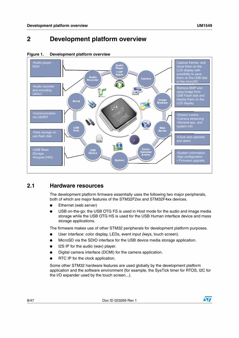
2 Development platform overview
Figure 1. Development platform overview
2.1 Hardware resourcesThe development platform firmware essentially uses the following two major peripherals, both of which are major features of the STM32F2xx and STM32F4xx devices.
● Ethernet (web server)
● USB on-the-go: the USB OTG FS is used in Host mode for the audio and image media storage while the USB OTG HS is used for the USB Human interface device and mass storage applications.
The firmware makes use of other STM32 peripherals for development platform purposes.
● User interface: color display, LEDs, event input (keys, touch screen).
● MicroSD via the SDIO interface for the USB device media storage application.
● I2S IP for the audio (wav) player.
● Digital camera interface (DCMI) for the camera application.
● RTC IP for the clock application.
Some other STM32 hardware features are used globally by the development platform application and the software environment (for example, the SysTick timer for RTOS, I2C for the I/O expander used by the touch screen...).
Retrieve BMP and Jpeg Image from USB Flash disk and display them on the LCD display
Capture frames and show them on the LCD display with possibility to save them on the USB disk or the microSD
•Distant control.•Camera streaming•General app and system info
•Clock and calendar and alarm
•System information.•App configuration• Firmware upgrade
•USB Mass Storage.•Keypad (HID)
•Data storage on usb flash disk
•Communication via USART
•Audio recorder and encoding (WAV)
•Audio player : WAV
Retrieve BMJpeg ImageUSB Flash ddisplay themLCD display
Capture framshow them oLCD displaypossibility tothem on theor the microS
•Distant cont•Camera stre•General appsystem infoff
•Clock and cand alarm
•System infoff•App configu• Firmware u
ass
(HID)
orage onh disk
nicationRT
ecorderoding
layer :
Retrieve BMP and Jpeg Image from USB Flash disk and display them on the LCD display
Capture frames and show them on the LCD display with possibility to save them on the USB disk or the microSD
•Distant control.•Camera streaming•General app and system info
•Clock and calendar and alarm
•System information.•App configuration• Firmware upgrade
•USB Mass Storage.•Keypad (HID)
•Data storage on usb flash disk
•Communication via USART
•Audio recorder and encoding (WAV)
•Audio player : WAV

UM1549 Development platform overview
Doc ID 023269 Rev 1 9/47
The camera application also uses the external SRAM embedded on the STM32xxG-EVAL board to store the camera frames via the DMA before they are output to the display through the GUI.
Figure 2. Hardware description
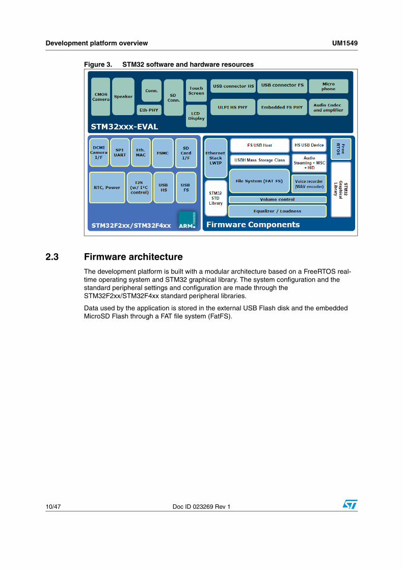
2.2 Software resourcesFigure 3 shows the different software and hardware resources used in the STM32 Demonstration Builder platform.
MS30290V1
Web server
Camera image flow on LCD(FSMC)
LCD with touchscreen
Calendar using the hardware RTC
calandar
HS USB mass storage
and HID devices
HS USB mass storage host
Development platform overview UM1549
10/47 Doc ID 023269 Rev 1
Figure 3. STM32 software and hardware resources
2.3 Firmware architectureThe development platform is built with a modular architecture based on a FreeRTOS real-time operating system and STM32 graphical library. The system configuration and the standard peripheral settings and configuration are made through the STM32F2xx/STM32F4xx standard peripheral libraries.
Data used by the application is stored in the external USB Flash disk and the embedded MicroSD Flash through a FAT file system (FatFS).

UM1549 Development platform overview
Doc ID 023269 Rev 1 11/47
Figure 4. Firmware architecture
The development platform application is built using the following software components.
● STM32F2xx Standard Peripherals Library
● STM32F4xx DSP and Standard Peripherals Library
● STM32 USB USB On-The-Go Host and Device Library
● STM32 graphical library and extension
● STM32 Audio Engine - Equalizer Library
● STM32 Audio Engine - Loudness Control Library
● STM32 Audio Engine - Mixer Library
● FreeRTOS
● LibJpeg library
● FatFS file system
● LwIP TCP/IP stack
Description of the demonstration startup process UM1549
12/47 Doc ID 023269 Rev 1
3 Description of the demonstration startup process
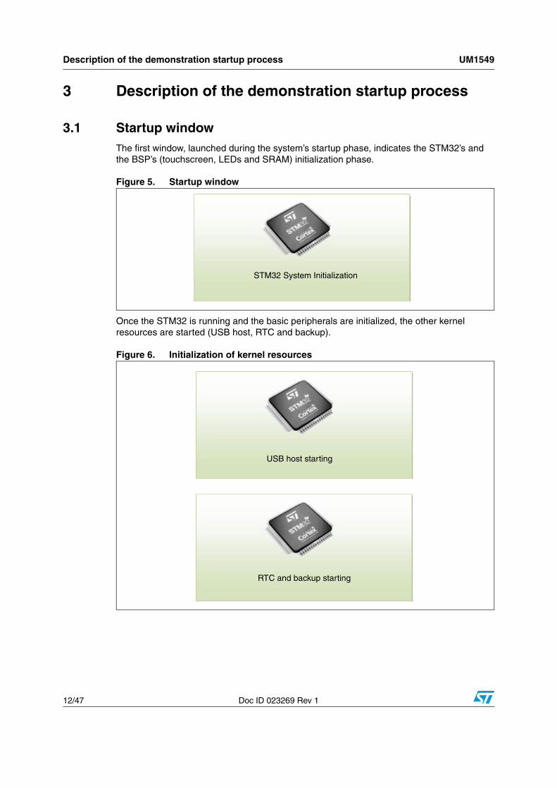
3.1 Startup windowThe first window, launched during the system’s startup phase, indicates the STM32’s and the BSP’s (touchscreen, LEDs and SRAM) initialization phase.
Figure 5. Startup window
Once the STM32 is running and the basic peripherals are initialized, the other kernel resources are started (USB host, RTC and backup).
Figure 6. Initialization of kernel resources
STM32 System Initialization
USB host starting
RTC and backup starting

UM1549 Description of the demonstration startup process
Doc ID 023269 Rev 1 13/47
3.2 Main menu windowsThe various module applications are classified into three categories: connectivity, multimedia and utilities.
Figure 7. Module applications
● Modules Zone: launches the module startup handler.
● System Time and Date: the update of the time and date are done by the kernel background task and can be re-adjusted in the Calendar Modules > Settings menu.
● Group Zone: contains the groups of modules. A group is a set of modules that have the same functions.
Note: The icons used in this demonstration are taken from http://commons.wikimedia.org/wiki/Crystal_Clear
3.2.1 Connectivity group window
The connectivity group contains the following modules.
Figure 8. Connectivity group
● Ethernet module: allows remote communication with the board over TCP/IP. The distant host can get video streams from the board (IP Cam) as well as system information.
● USB Device: set of USB applications based on the mass storage class using the embedded SD card and HID class using the embedded touchscreen.
● Serial: a graphical interface that allows sending ASCII characters through the RS-232.
MS30292V1
Group zone
Modules zone
System time and date
Current background process date
Description of the demonstration startup process UM1549
14/47 Doc ID 023269 Rev 1
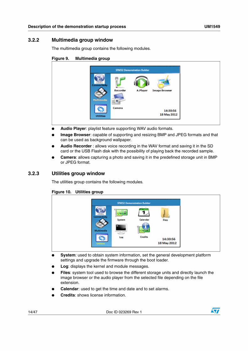
3.2.2 Multimedia group window
The multimedia group contains the following modules.
Figure 9. Multimedia group
● Audio Player: playlist feature supporting WAV audio formats.
● Image Browser: capable of supporting and resizing BMP and JPEG formats and that can be used as background wallpaper.
● Audio Recorder : allows voice recording in the WAV format and saving it in the SD card or the USB Flash disk with the possibility of playing back the recorded sample.
● Camera: allows capturing a photo and saving it in the predefined storage unit in BMP or JPEG format.
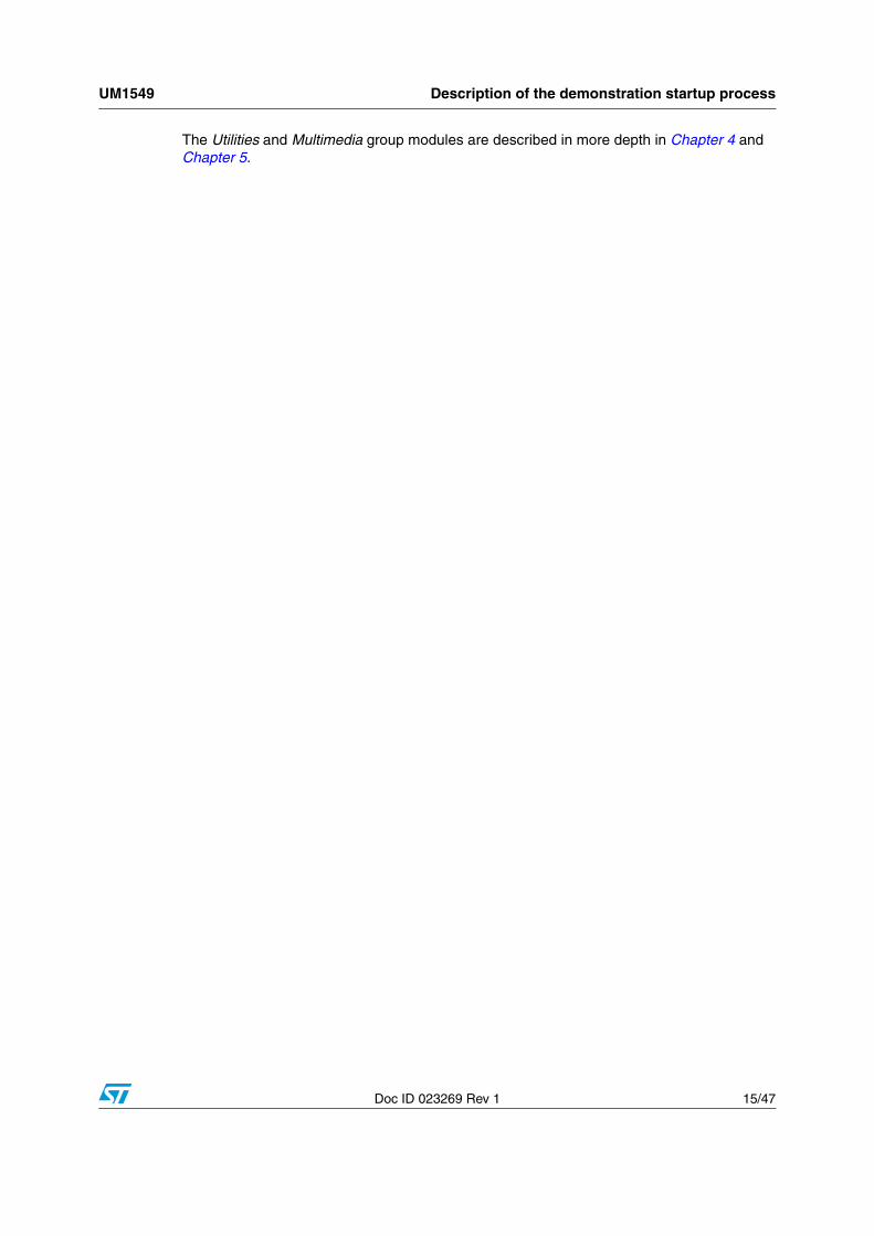
3.2.3 Utilities group window
The utilities group contains the following modules.
Figure 10. Utilities group
● System: used to obtain system information, set the general development platform settings and upgrade the firmware through the boot loader.
● Log: displays the kernel and module messages.
● Files: system tool used to browse the different storage units and directly launch the image browser or the audio player from the selected file depending on the file extension.
● Calendar: used to get the time and date and to set alarms.
● Credits: shows license information.
UM1549 Description of the demonstration startup process
Doc ID 023269 Rev 1 15/47
The Utilities and Multimedia group modules are described in more depth in Chapter 4 and Chapter 5.
Description of Utilities group applications UM1549
16/47 Doc ID 023269 Rev 1
4 Description of Utilities group applications
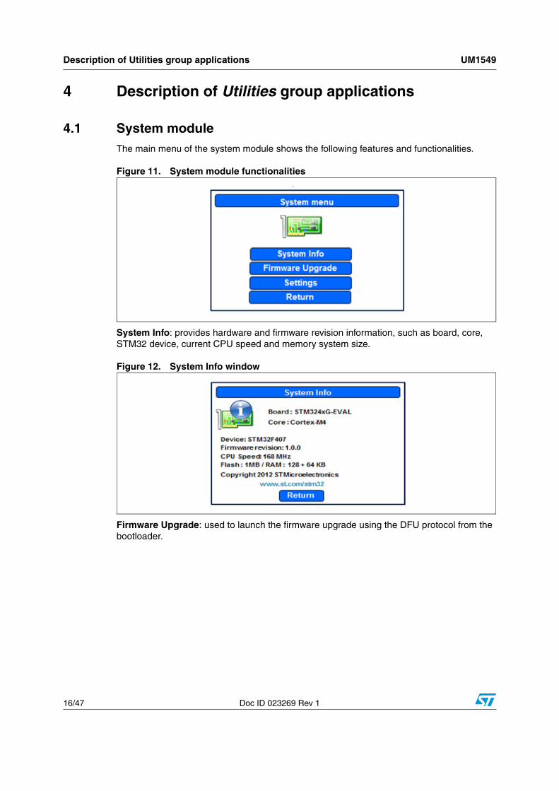
4.1 System moduleThe main menu of the system module shows the following features and functionalities.
Figure 11. System module functionalities
System Info: provides hardware and firmware revision information, such as board, core, STM32 device, current CPU speed and memory system size.
Figure 12. System Info window
Firmware Upgrade: used to launch the firmware upgrade using the DFU protocol from the bootloader.

UM1549 Description of Utilities group applications
Doc ID 023269 Rev 1 17/47
Figure 13. Upgrade window
When the Upgrade button is activated, the Demonstration Builder application jumps to the internal boot ROM memory (system memory) of the STM32 device. For more information about the boot loader, refer to AN260 "STM32™ microcontroller system memory boot mode".
Since the Demonstration Builder application runs in un-privileged mode, the jump process should be performed within an interrupt handler (supervisor mode). The jump is performed in the systick handler after cleaning up the resources shared with the boot loader code, in this case the USB OTG core.
Figure 14. Bootloader startup window
Once the boot loader is running, the Demonstration Builder application stops running and the upgrade module freezes. The board should be reset after the upgrade process. Note that during the firmware download, the upgrade page shows the following message.
Figure 15. Bootloader process window
Freeing USB FS resources
Bootloader running...
Description of Utilities group applications UM1549
18/47 Doc ID 023269 Rev 1
Settings: general system settings allow you to:
● Enable/disable the distant control feature for the modules supporting it.
● Enable/disable the background feature for the modules supporting it.
● Enable/disable the low-power mode.
● Enable/disable the LCD power saving.
Note: Enabling the distant control feature will automatically enable the background feature. the background module feature can not be disabled when one of the background process is currently running.
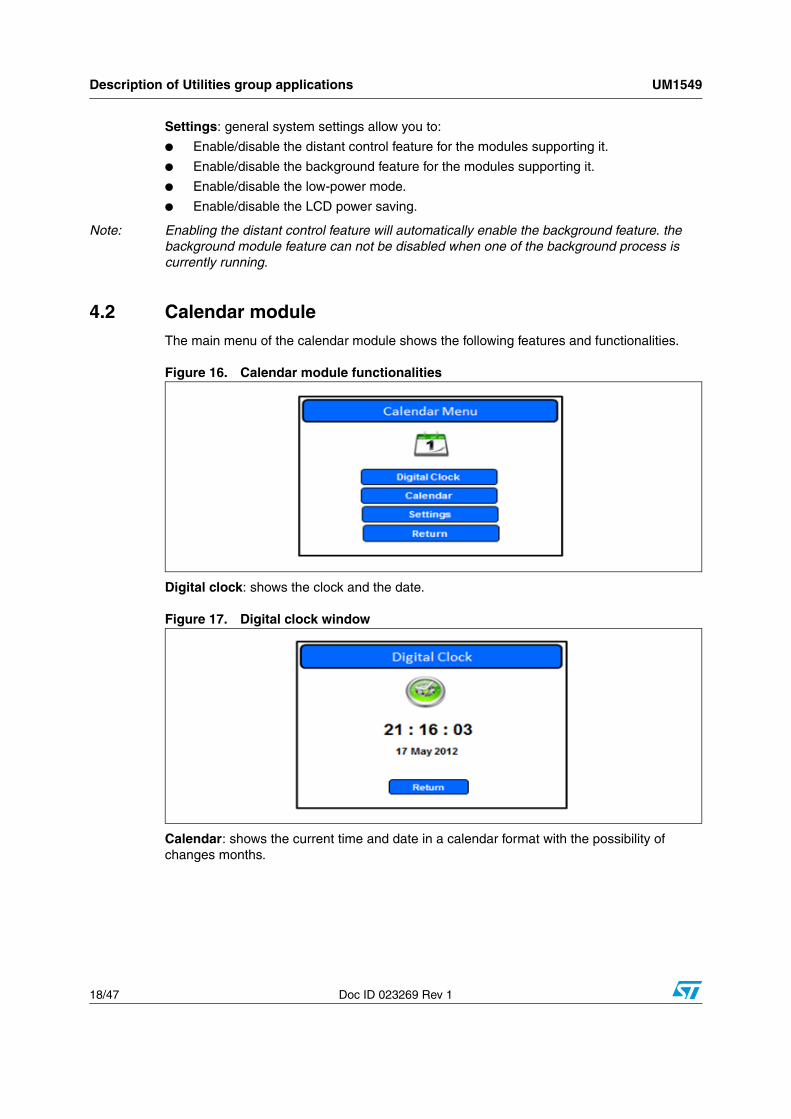
4.2 Calendar moduleThe main menu of the calendar module shows the following features and functionalities.
Figure 16. Calendar module functionalities
Digital clock: shows the clock and the date.
Figure 17. Digital clock window
Calendar: shows the current time and date in a calendar format with the possibility of changes months.
UM1549 Description of Utilities group applications
Doc ID 023269 Rev 1 19/47
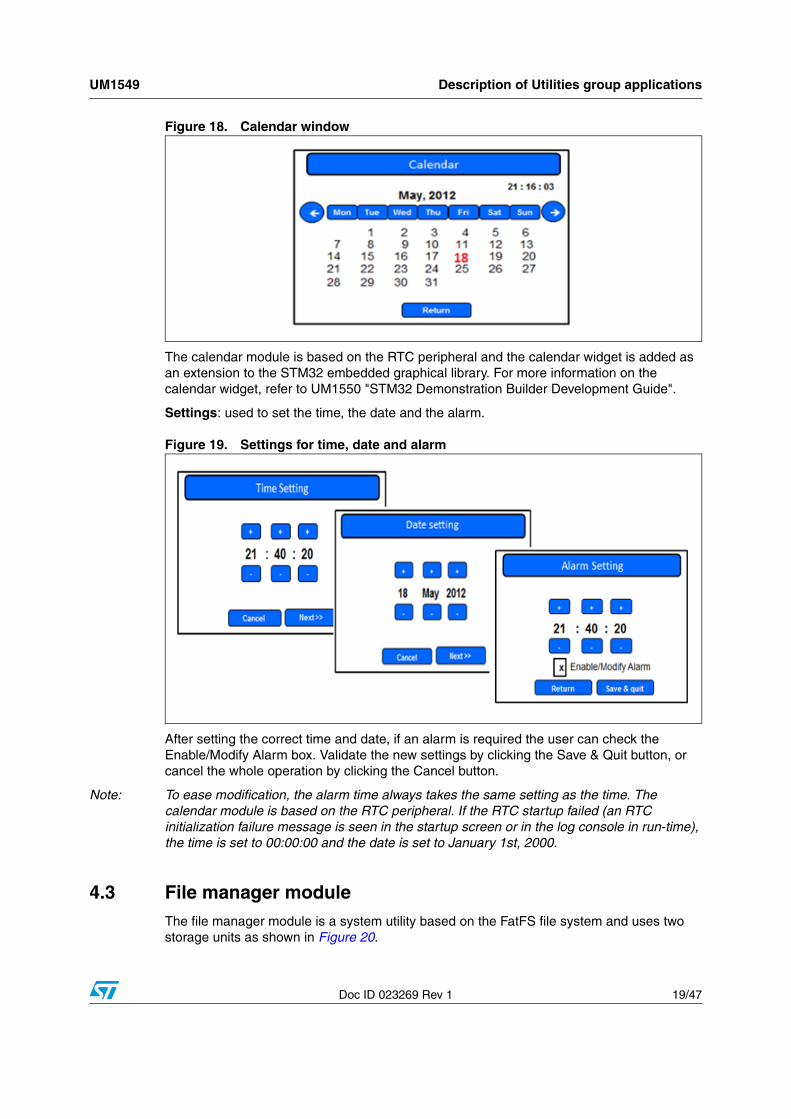
Figure 18. Calendar window
The calendar module is based on the RTC peripheral and the calendar widget is added as an extension to the STM32 embedded graphical library. For more information on the calendar widget, refer to UM1550 "STM32 Demonstration Builder Development Guide".
Settings: used to set the time, the date and the alarm.
Figure 19. Settings for time, date and alarm
After setting the correct time and date, if an alarm is required the user can check the Enable/Modify Alarm box. Validate the new settings by clicking the Save & Quit button, or cancel the whole operation by clicking the Cancel button.
Note: To ease modification, the alarm time always takes the same setting as the time. The calendar module is based on the RTC peripheral. If the RTC startup failed (an RTC initialization failure message is seen in the startup screen or in the log console in run-time), the time is set to 00:00:00 and the date is set to January 1st, 2000.
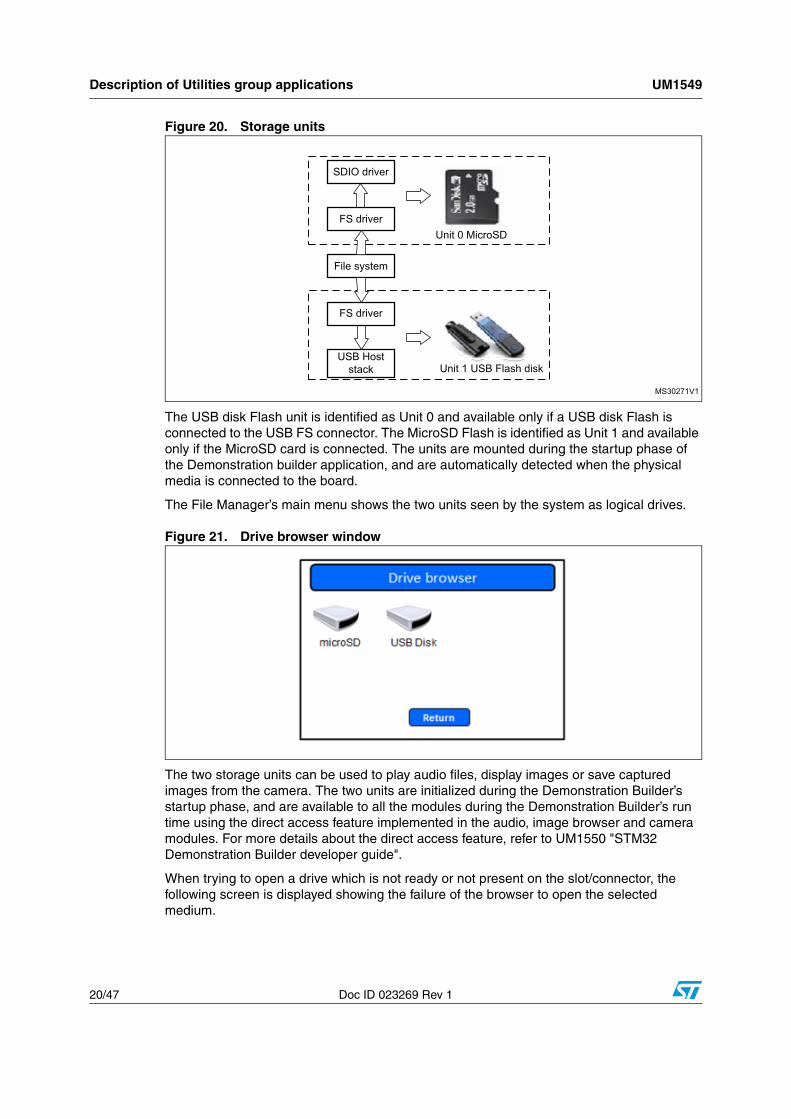
4.3 File manager moduleThe file manager module is a system utility based on the FatFS file system and uses two storage units as shown in Figure 20.
Description of Utilities group applications UM1549
20/47 Doc ID 023269 Rev 1
Figure 20. Storage units
The USB disk Flash unit is identified as Unit 0 and available only if a USB disk Flash is connected to the USB FS connector. The MicroSD Flash is identified as Unit 1 and available only if the MicroSD card is connected. The units are mounted during the startup phase of the Demonstration builder application, and are automatically detected when the physical media is connected to the board.
The File Manager’s main menu shows the two units seen by the system as logical drives.
Figure 21. Drive browser window
The two storage units can be used to play audio files, display images or save captured images from the camera. The two units are initialized during the Demonstration Builder’s startup phase, and are available to all the modules during the Demonstration Builder’s run time using the direct access feature implemented in the audio, image browser and camera modules. For more details about the direct access feature, refer to UM1550 "STM32 Demonstration Builder developer guide".
When trying to open a drive which is not ready or not present on the slot/connector, the following screen is displayed showing the failure of the browser to open the selected medium.
MS30271V1
SDIO driver
FS driver
FS driver
USB Host stack
File system
Unit 0 MicroSD
Unit 1 USB Flash disk
UM1549 Description of Utilities group applications
Doc ID 023269 Rev 1 21/47
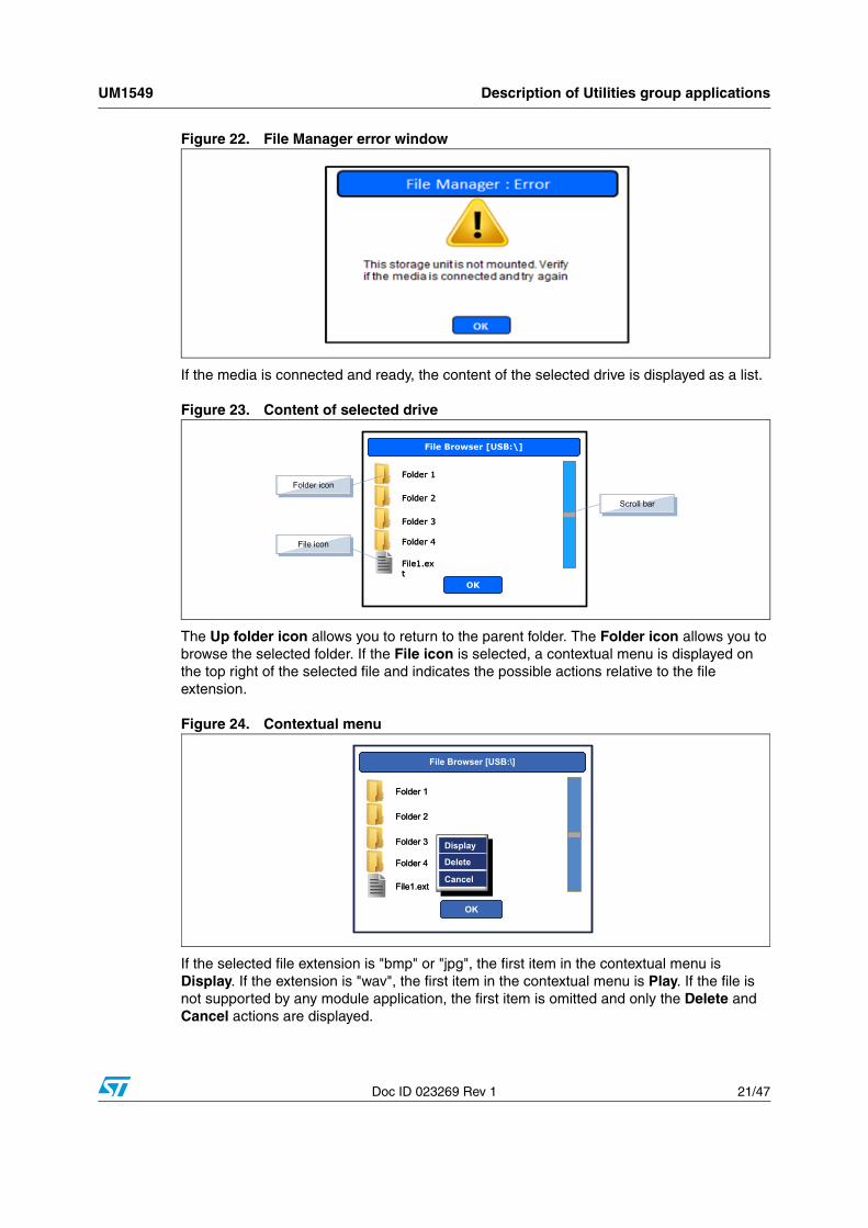
Figure 22. File Manager error window
If the media is connected and ready, the content of the selected drive is displayed as a list.
Figure 23. Content of selected drive
The Up folder icon allows you to return to the parent folder. The Folder icon allows you to browse the selected folder. If the File icon is selected, a contextual menu is displayed on the top right of the selected file and indicates the possible actions relative to the file extension.
Figure 24. Contextual menu
If the selected file extension is "bmp" or "jpg", the first item in the contextual menu is Display. If the extension is "wav", the first item in the contextual menu is Play. If the file is not supported by any module application, the first item is omitted and only the Delete and Cancel actions are displayed.
File Browser [USB:\]
OK
Folder 1
Folder 3
Folder 2
Folder 4
File1.ext
File Browser [USB:\]File Browser [USB:\]
OK
Folder 1
Folder 3
Folder 2
Folder 4
File1.ext
Folder icon
File icon
Scroll bar
File Browser [USB:\]
OK
Folder 1
Folder 3
Folder 2
Folder 4
File1.ext
Display
Delete
Cancel
File Browser [USB:\]File Browser [USB:\]
OK
Folder 1
Folder 3
Folder 2
Folder 4
File1.ext
Display
Delete
Cancel
Display
Delete
Cancel
Description of Utilities group applications UM1549
22/47 Doc ID 023269 Rev 1
The scroll bar appears automatically when the number of available items on a folder exceeds the maximum possible displayed lines and disappears when it is not the case.
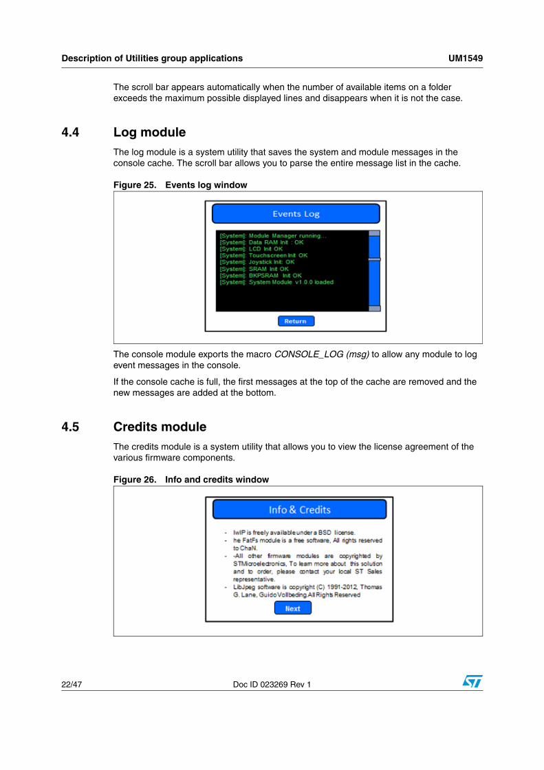
4.4 Log moduleThe log module is a system utility that saves the system and module messages in the console cache. The scroll bar allows you to parse the entire message list in the cache.
Figure 25. Events log window
The console module exports the macro CONSOLE_LOG (msg) to allow any module to log event messages in the console.
If the console cache is full, the first messages at the top of the cache are removed and the new messages are added at the bottom.
4.5 Credits moduleThe credits module is a system utility that allows you to view the license agreement of the various firmware components.
Figure 26. Info and credits window
UM1549 Description of Multimedia group applications
Doc ID 023269 Rev 1 23/47
5 Description of Multimedia group applications
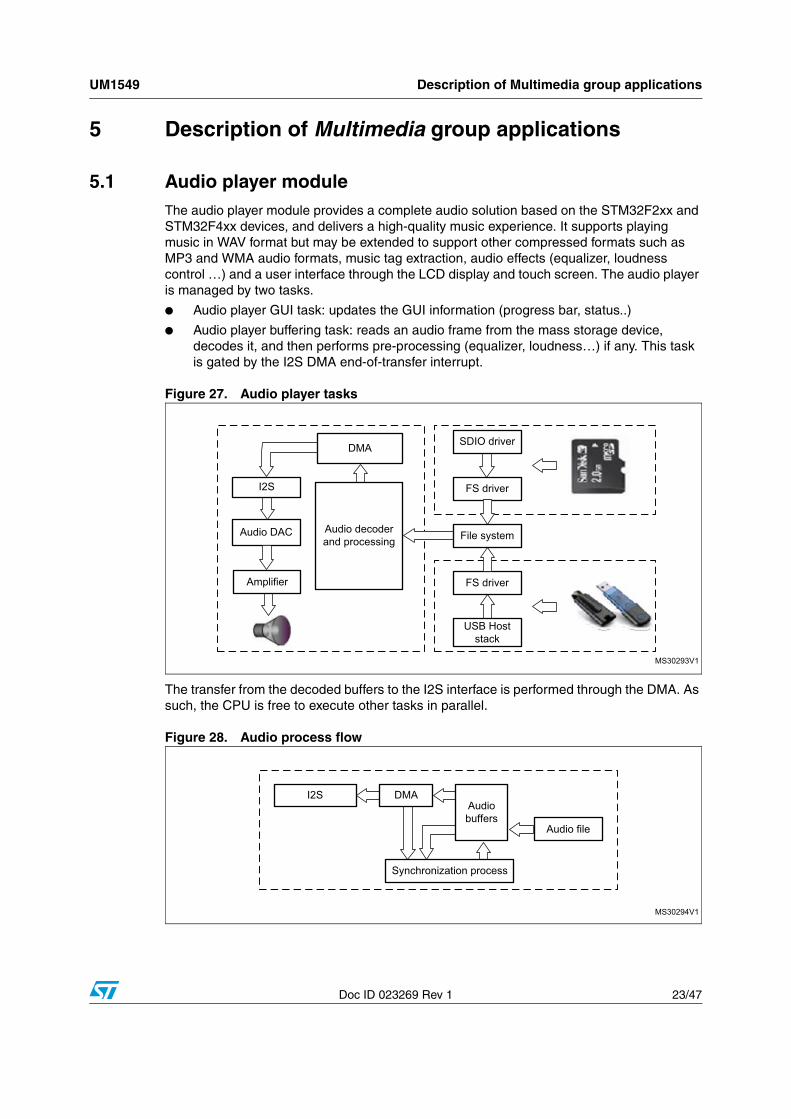
5.1 Audio player moduleThe audio player module provides a complete audio solution based on the STM32F2xx and STM32F4xx devices, and delivers a high-quality music experience. It supports playing music in WAV format but may be extended to support other compressed formats such as MP3 and WMA audio formats, music tag extraction, audio effects (equalizer, loudness control …) and a user interface through the LCD display and touch screen. The audio player is managed by two tasks.
● Audio player GUI task: updates the GUI information (progress bar, status..)
● Audio player buffering task: reads an audio frame from the mass storage device, decodes it, and then performs pre-processing (equalizer, loudness…) if any. This task is gated by the I2S DMA end-of-transfer interrupt.
Figure 27. Audio player tasks
The transfer from the decoded buffers to the I2S interface is performed through the DMA. As such, the CPU is free to execute other tasks in parallel.
Figure 28. Audio process flow
MS30293V1
SDIO driver
FS driver
FS driver
USB Host stack
Audio decoder and processing
Audio DAC
I2S
DMA
Amplifier
File system
MS30294V1
Audio file
Audio buffers
Synchronization process
I2S DMA
Description of Multimedia group applications UM1549
24/47 Doc ID 023269 Rev 1
While the DMA is outputting a buffer, the application manages the read/decode process of other buffers. Multi-buffering is used for this module.
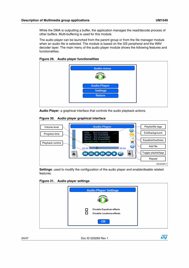
The audio player can be launched from the parent group or from the file manager module when an audio file is selected. The module is based on the I2S peripheral and the WAV decoder layer. The main menu of the audio player module shows the following features and functionalities.
Figure 29. Audio player functionalities
Audio Player: a graphical interface that controls the audio playback actions.
Figure 30. Audio player graphical interface
Settings: used to modify the configuration of the audio player and enable/disable related features.
Figure 31. Audio player settings
MS30295V1
Playlist/file tags
Exit/background
Equalize/loudness
Add file
Toggle playlist/tags
Repeat
Volume level
Progress time
Playback control

UM1549 Description of Multimedia group applications
Doc ID 023269 Rev 1 25/47
The audio player supports a background feature. The graphical interface can be deactivated while the audio process runs in background mode, thus allowing another module to run simultaneously.
To switch to background mode, the user must click on the exit button (see Figure 30). A contextual menu appears.
Figure 32. Switching to background mode
● Close: turns off the audio player.
● Background: disables the graphical interface and keeps the audio background process running.
● Cancel: abandons the user action.
To restore the graphical interface, the user has to relaunch the audio player from the multimedia group or select an audio file in the file browser and click on play in the contextual menu as described in Section 4.3: File manager module.
The user can adjust the loudness and the equalizer settings by activating the audio equalizer frame.
Figure 33. Audio equalizer window
Four frequency bands are handled by the equalizer: 1 kHz, 3 kHz and 18 kHz, and may be adjusted between -5 db and 5 db.
Description of Multimedia group applications UM1549
26/47 Doc ID 023269 Rev 1
5.1.1 Audio player module features
The audio player embeds the following features.
● Full user interface for equalizer and loudness: GUI, touch screen.
● File browser: SD card and USB key.
● Playlist management.
● Playback features: Play, Pause, Stop, Fast Forward/Rewind, Next, Previous, Repeat Single/All, Volume, Mute, Progress Bar…
● File information display (title, artist, album…)
● Graphic equalizer
● Background playing (multi-task)
5.1.2 Supported audio formats
The audio player supports all wav PCM audio files with the following configurations.
● Sample rate: 8 to 96 kHz.
● Channel number: stereo/mono
● Audio data format: 16 bits
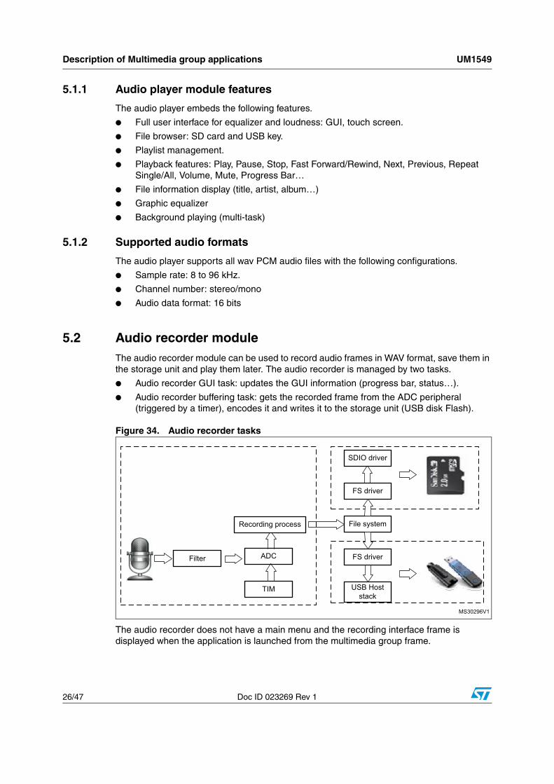
5.2 Audio recorder moduleThe audio recorder module can be used to record audio frames in WAV format, save them in the storage unit and play them later. The audio recorder is managed by two tasks.
● Audio recorder GUI task: updates the GUI information (progress bar, status…).
● Audio recorder buffering task: gets the recorded frame from the ADC peripheral (triggered by a timer), encodes it and writes it to the storage unit (USB disk Flash).
Figure 34. Audio recorder tasks
The audio recorder does not have a main menu and the recording interface frame is displayed when the application is launched from the multimedia group frame.
MS30296V1
SDIO driver
FS driver
FS driver
USB Host stack
File system
Filter
TIM
ADC
Recording process

UM1549 Description of Multimedia group applications
Doc ID 023269 Rev 1 27/47
Figure 35. Audio recorder user interface window
When the recording process is started, the audio recorder’s action buttons change so as to allow the user to control the progress.
Figure 36. Audio recorder user interface recording progress
5.3 Image browser moduleThe image browser module supports BMP and JPEG formats. It also has scaling and image effects features.
The BMP and JPEG images are stored in the storage units. The source folder for the browser and the display time, if enabled, can be selected and configured in the browser setting frame. Once the image format has been identified, the parser calls the adequate decoder, scales the image to fit to the display zone, applies the image effect selected in the image effects frame, and then displays the processed image on the image browser frame.
Regarding the JPEG decoder, the LibJpeg library is used and configured to support images with a smaller size than the 1024 x 768 resolution for RAM resources, but can be changed by increasing the size of the heap memory.
Elapsed time
Stop recording and save file
Pause current recording
Stop recording and remove recorded data from the
storage unit
Description of Multimedia group applications UM1549
28/47 Doc ID 023269 Rev 1
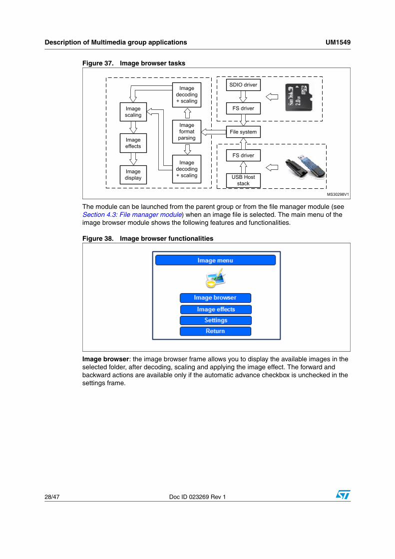
Figure 37. Image browser tasks
The module can be launched from the parent group or from the file manager module (see Section 4.3: File manager module) when an image file is selected. The main menu of the image browser module shows the following features and functionalities.
Figure 38. Image browser functionalities
Image browser: the image browser frame allows you to display the available images in the selected folder, after decoding, scaling and applying the image effect. The forward and backward actions are available only if the automatic advance checkbox is unchecked in the settings frame.
MS30298V1
SDIO driver
FS driver
FS driver
USB Host stack
File systemImage format parsing
Image decoding + scaling
Image effects
Image display
Image scaling
Image decoding + scaling
UM1549 Description of Multimedia group applications
Doc ID 023269 Rev 1 29/47
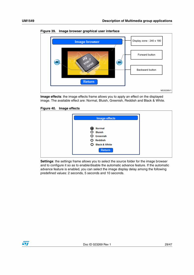
Figure 39. Image browser graphical user interface
Image effects: the image effects frame allows you to apply an effect on the displayed image. The available effect are: Normal, Bluish, Greenish, Reddish and Black & White.
Figure 40. Image effects
Settings: the settings frame allows you to select the source folder for the image browser and to configure it so as to enable/disable the automatic advance feature. If the automatic advance feature is enabled, you can select the image display delay among the following predefined values: 2 seconds, 5 seconds and 10 seconds.
MS30299V1
Display zone : 240 x 180
Forward button
Backward button

Description of Multimedia group applications UM1549
30/47 Doc ID 023269 Rev 1
Figure 41. Browser settings
The Folder Browser action uses the file manager module to explore the storage units and select the source folder through the FILMGR_DirectEx method using the direct access feature.
For more information about the direct access feature, refer to UM1550 "STM32 Demonstration Builder Developer Guide". A contextual menu is displayed when each folder icon is clicked that enables the user to either select, browse or cancel.
Figure 42. File browser window
Select: sets the selected folder as the source path for the images.
Browse: shows the content of the selected folder.
The Image browser supports the following image formats.
Table 2. Image formats
Resolution Compression Bpp
BMP 160 x 120 to 1024 x 768 No 16/24
JPEG 160 x 120 to 1024 x 768 Yes 16/24
MS31100V1
Enable/disable automatic advance
Display delay
Folder browser

UM1549 Description of Multimedia group applications
Doc ID 023269 Rev 1 31/47
5.4 Camera moduleThe camera module retrieves the raw data and displays it on the LCD with the possibility of saving the captured frame in a BMP or JPEG format in the storage units. The destination folder and the capture image format can be selected and configured in the camera setting frame.
The camera module uses the DCMI interface (16 bits) to capture the data frame from the camera and put it in the external SRAM in QVGA mode (320 x 240), after applying the image effect defined in the settings frame. Once the data is in the external SRAM, it is resized to QQVGA 160x120 format and displayed in the camera capture display zone. If the capture is activated, the DCMI is temporary suspended and the last available image on the external SRAM is converted into a 24-bit Bpp format and then encoded and saved to a BMP or JPEG format in the destination folder following the parameters set in the camera settings frame.
Figure 43. Camera module
For the JPEG encoder, the LibJpeg library is called and the following parameters are used.
● Resolution : 320 x 240
● BPP: 24
● Color space: RGB
● Quality : 100%
For the BMP format, a bmp header with the following parameters is added to the top of the raw data (24 bits) and then saved to the selected storage unit.
● Resolution : 320 x 240
● BPP: 24
● Format: RGB
● Compression : No
The main menu of the camera module shows the following features and functionalities.
MS31101V1
SDIO driver
FS driver
FS driver
USB Host stack
File system
JPEG encoder
BMP encoder
Imag
e Fo
rmat
sel
ecto
r
Image scaling
Image display
Image effects
SRAM
Camera capture process
Description of Multimedia group applications UM1549
32/47 Doc ID 023269 Rev 1
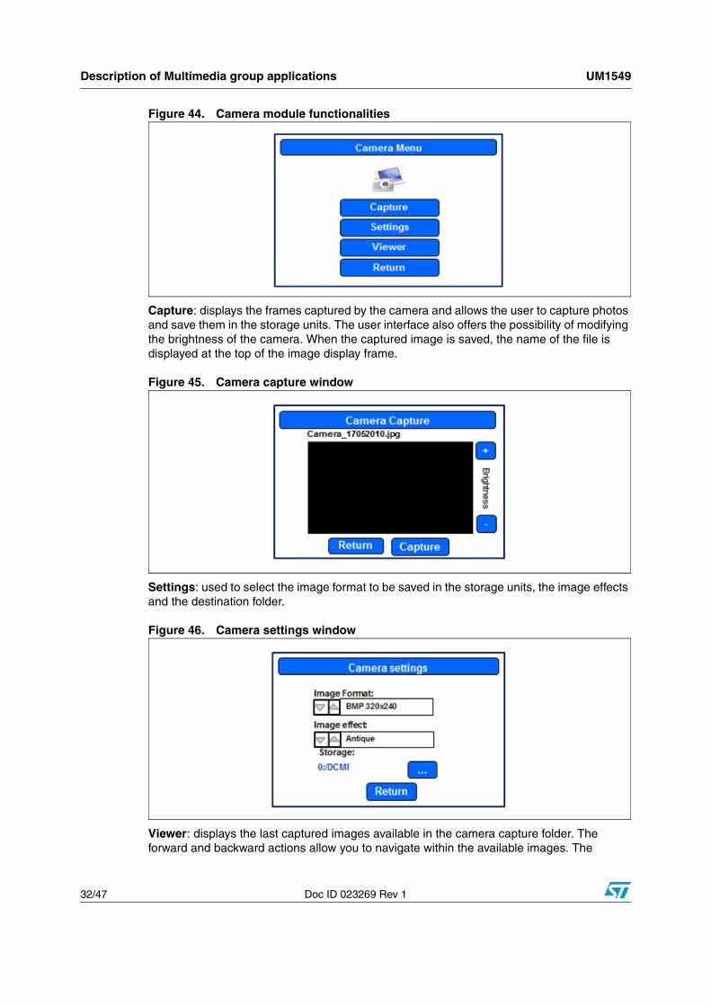
Figure 44. Camera module functionalities
Capture: displays the frames captured by the camera and allows the user to capture photos and save them in the storage units. The user interface also offers the possibility of modifying the brightness of the camera. When the captured image is saved, the name of the file is displayed at the top of the image display frame.
Figure 45. Camera capture window
Settings: used to select the image format to be saved in the storage units, the image effects and the destination folder.
Figure 46. Camera settings window
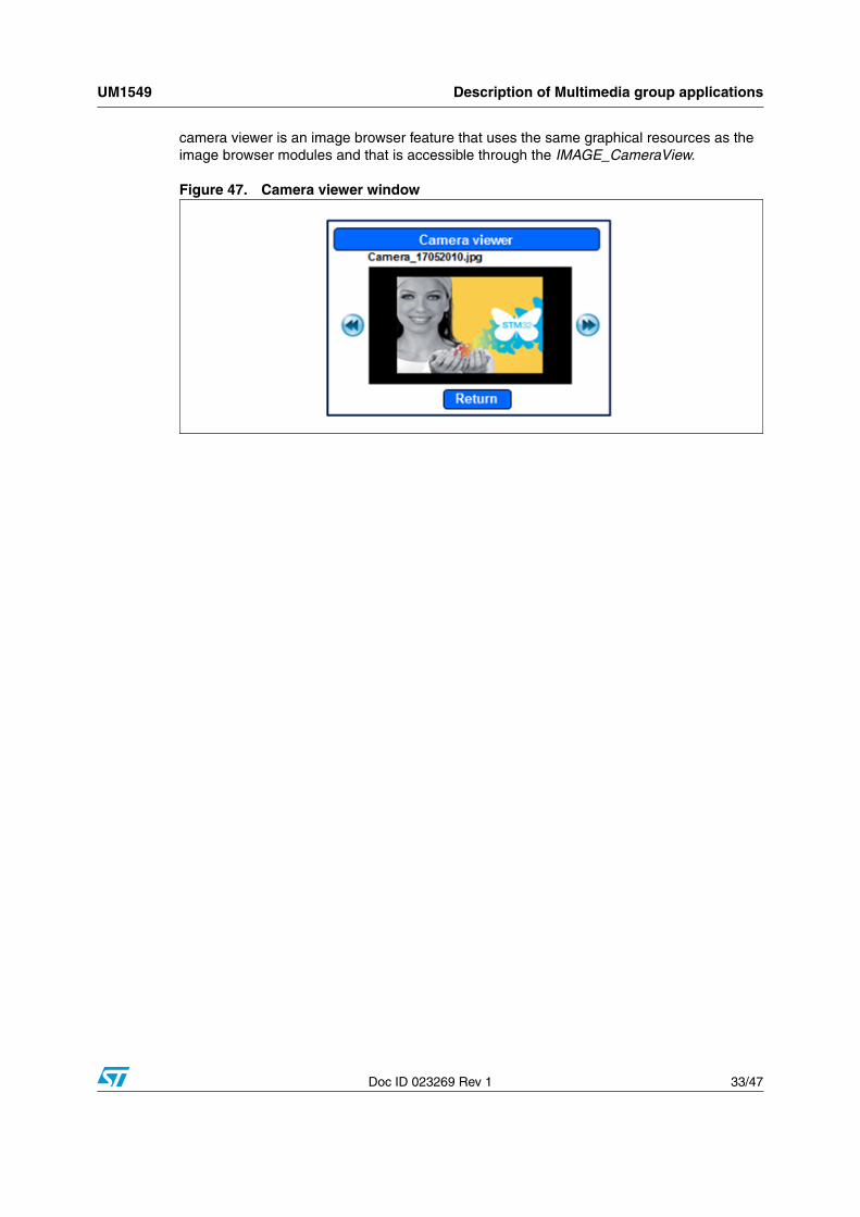
Viewer: displays the last captured images available in the camera capture folder. The forward and backward actions allow you to navigate within the available images. The
UM1549 Description of Multimedia group applications
Doc ID 023269 Rev 1 33/47
camera viewer is an image browser feature that uses the same graphical resources as the image browser modules and that is accessible through the IMAGE_CameraView.
Figure 47. Camera viewer window
Description of Connectivity group applications UM1549
34/47 Doc ID 023269 Rev 1
6 Description of Connectivity group applications
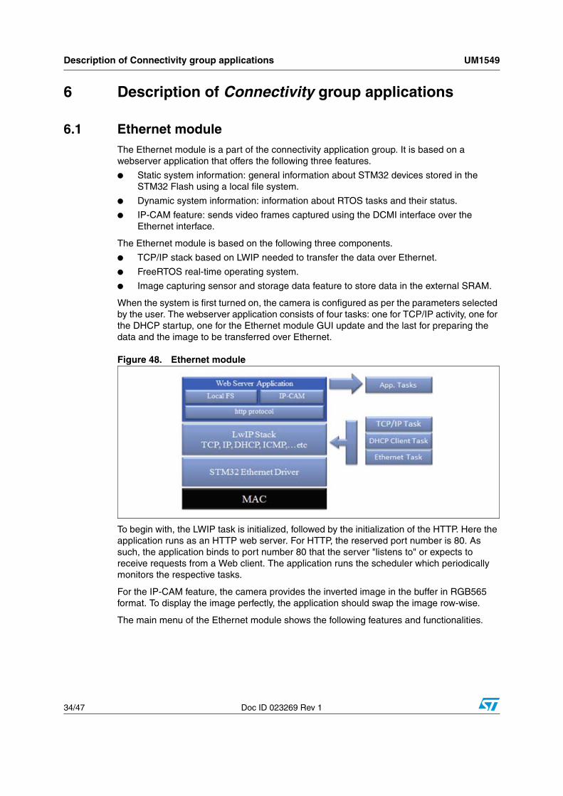
6.1 Ethernet moduleThe Ethernet module is a part of the connectivity application group. It is based on a webserver application that offers the following three features.
● Static system information: general information about STM32 devices stored in the STM32 Flash using a local file system.
● Dynamic system information: information about RTOS tasks and their status.
● IP-CAM feature: sends video frames captured using the DCMI interface over the Ethernet interface.
The Ethernet module is based on the following three components.
● TCP/IP stack based on LWIP needed to transfer the data over Ethernet.
● FreeRTOS real-time operating system.
● Image capturing sensor and storage data feature to store data in the external SRAM.
When the system is first turned on, the camera is configured as per the parameters selected by the user. The webserver application consists of four tasks: one for TCP/IP activity, one for the DHCP startup, one for the Ethernet module GUI update and the last for preparing the data and the image to be transferred over Ethernet.
Figure 48. Ethernet module
To begin with, the LWIP task is initialized, followed by the initialization of the HTTP. Here the application runs as an HTTP web server. For HTTP, the reserved port number is 80. As such, the application binds to port number 80 that the server "listens to" or expects to receive requests from a Web client. The application runs the scheduler which periodically monitors the respective tasks.
For the IP-CAM feature, the camera provides the inverted image in the buffer in RGB565 format. To display the image perfectly, the application should swap the image row-wise.
The main menu of the Ethernet module shows the following features and functionalities.
UM1549 Description of Connectivity group applications
Doc ID 023269 Rev 1 35/47
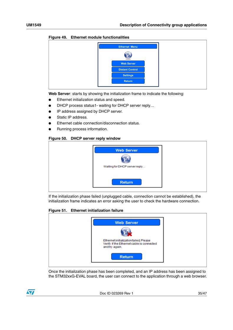
Figure 49. Ethernet module functionalities
Web Server: starts by showing the initialization frame to indicate the following:
● Ethernet initialization status and speed.
● DHCP process status1- waiting for DHCP server reply…
● IP address assigned by DHCP server.
● Static IP address.
● Ethernet cable connection/disconnection status.
● Running process information.
Figure 50. DHCP server reply window
If the initialization phase failed (unplugged cable, connection cannot be established), the initialization frame indicates an error asking the user to check the hardware connection.
Figure 51. Ethernet initialization failure
Once the initialization phase has been completed, and an IP address has been assigned to the STM32xxG-EVAL board, the user can connect to the application through a web browser.
Ethernet MenuEthernet Menu
Return
Distant Control
Settings
Web Server

Description of Connectivity group applications UM1549
36/47 Doc ID 023269 Rev 1
Settings: enables/disables the DHCP protocol and the IP-CAM image format.
Figure 52. Settings menu window
Distant Control: when clicked, the Ethernet main menu is closed and the Ethernet web server/remote control starts working as a background task.
6.1.1 Using the webserver application
Before launching the webserver application:
● ensure the camera is perfectly fitted on the board.
● ensure that all the jumpers are correctly connected.
● connect the board to the LAN (local area network) using an Ethernet cable or connect the board directly to the PC using an Ethernet switch/hub to test the functionality of the board as shown in Figure 53.
Figure 53. Connecting the board
Once the IP address is assigned (through DHCP or assigned statically), the user can view the image captured by the camera through a computer on the network using a standard web browser.
To obtain the system information data or the image in a web browser, you must type the IP address of the board in the address bar of the browser as shown in Figure 54.
MS31102V1
Board connected to the LAN Board connected directly to the PC using a hub
UM1549 Description of Connectivity group applications
Doc ID 023269 Rev 1 37/47
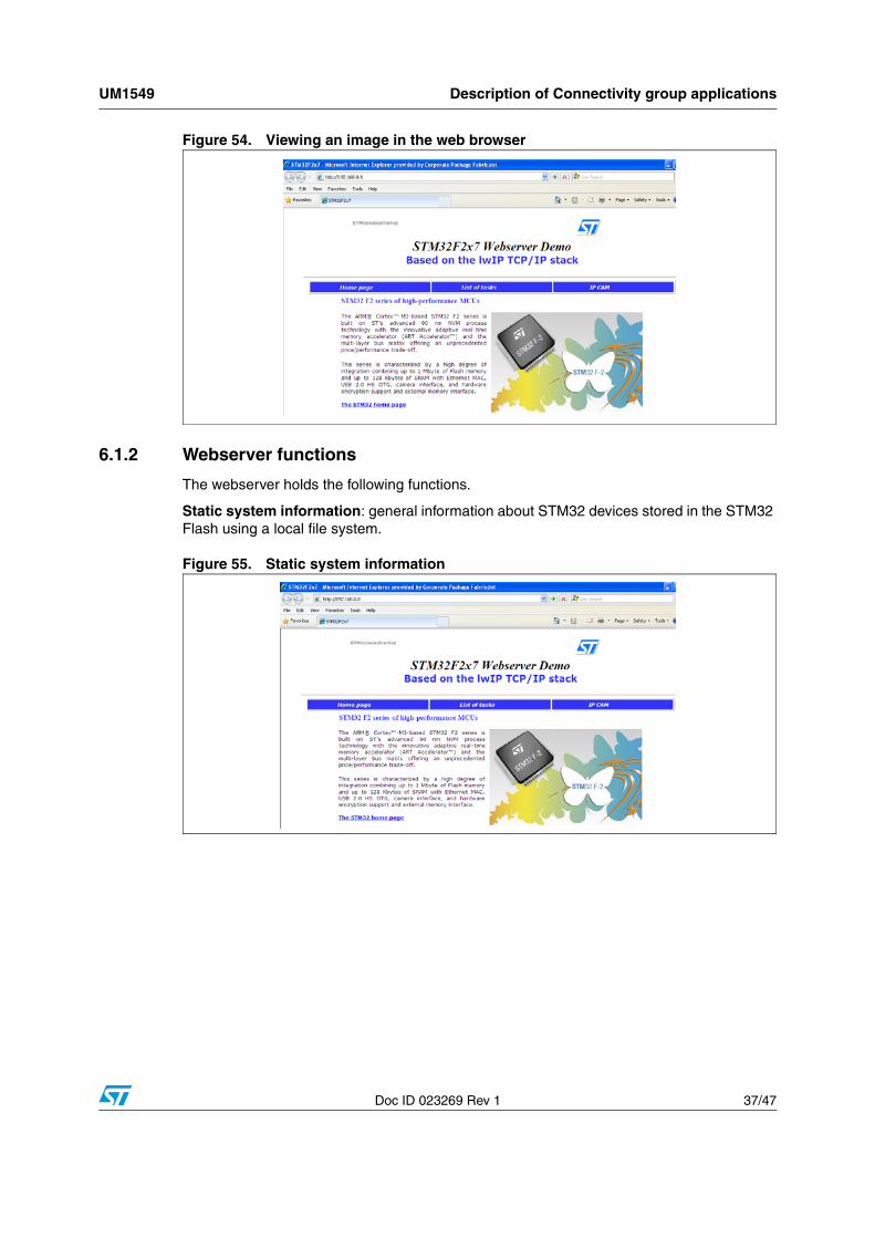
Figure 54. Viewing an image in the web browser
6.1.2 Webserver functions
The webserver holds the following functions.
Static system information: general information about STM32 devices stored in the STM32 Flash using a local file system.
Figure 55. Static system information

Description of Connectivity group applications UM1549
38/47 Doc ID 023269 Rev 1
Dynamic system information: information about RTOS tasks and their status.
Figure 56. Dynamic system information
IP-CAM feature: sends captured video frames using the DCMI interface over the Ethernet interface.
Figure 57. IP-CAM feature
6.1.3 Distant Control functions
The Distant Control holds the following functions.
Change system configuration: Allows you to modify the System module configuration. To enable/disable a specific feature, first check/uncheck its corresponding checkbox as shown in the figure below. Then click the "Send" button to submit the new configuration.
UM1549 Description of Connectivity group applications
Doc ID 023269 Rev 1 39/47
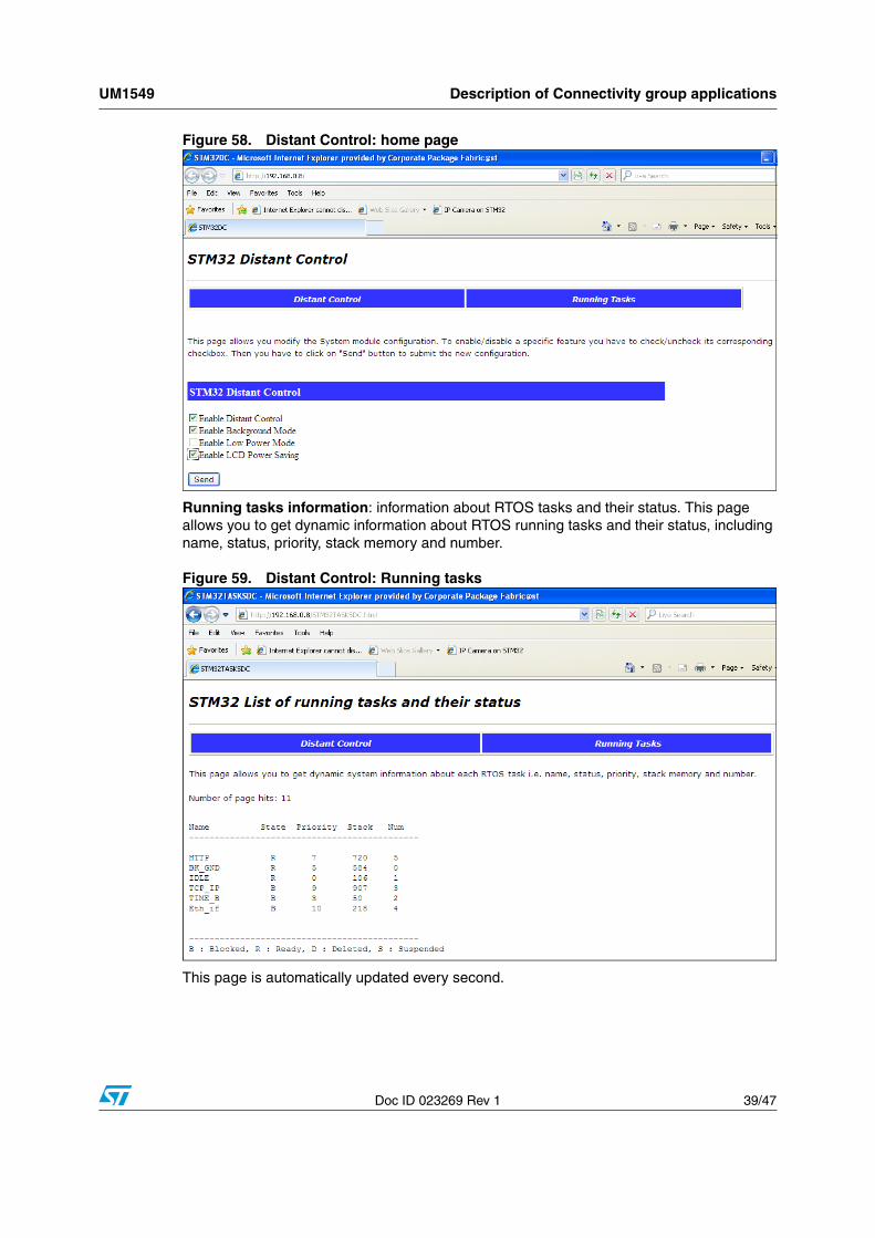
Figure 58. Distant Control: home page
Running tasks information: information about RTOS tasks and their status. This page allows you to get dynamic information about RTOS running tasks and their status, including name, status, priority, stack memory and number.
Figure 59. Distant Control: Running tasks
This page is automatically updated every second.
Description of Connectivity group applications UM1549
40/47 Doc ID 023269 Rev 1
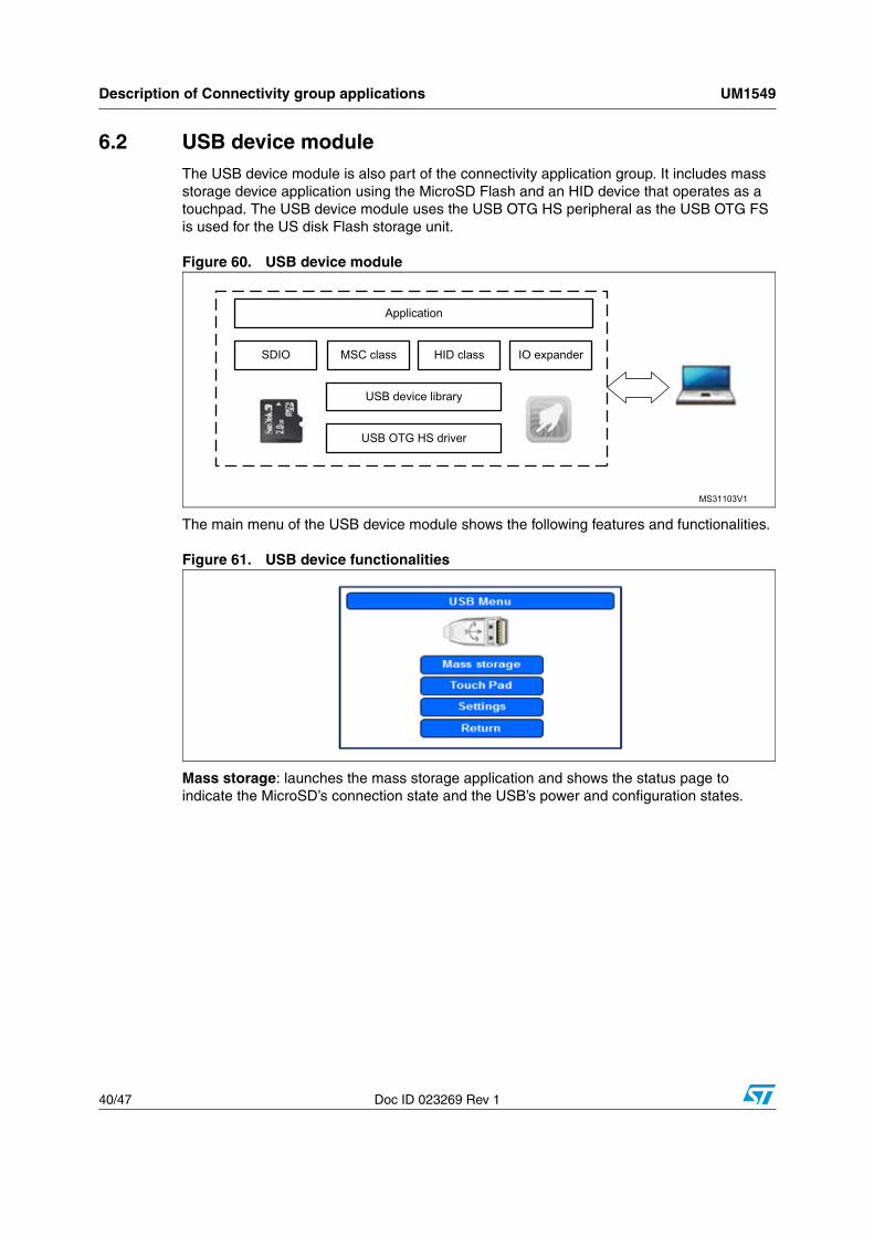
6.2 USB device moduleThe USB device module is also part of the connectivity application group. It includes mass storage device application using the MicroSD Flash and an HID device that operates as a touchpad. The USB device module uses the USB OTG HS peripheral as the USB OTG FS is used for the US disk Flash storage unit.
Figure 60. USB device module
The main menu of the USB device module shows the following features and functionalities.
Figure 61. USB device functionalities
Mass storage: launches the mass storage application and shows the status page to indicate the MicroSD’s connection state and the USB’s power and configuration states.
MS31103V1
Application
USB device library
SDIO MSC class HID class IO expander
USB OTG HS driver
UM1549 Description of Connectivity group applications
Doc ID 023269 Rev 1 41/47
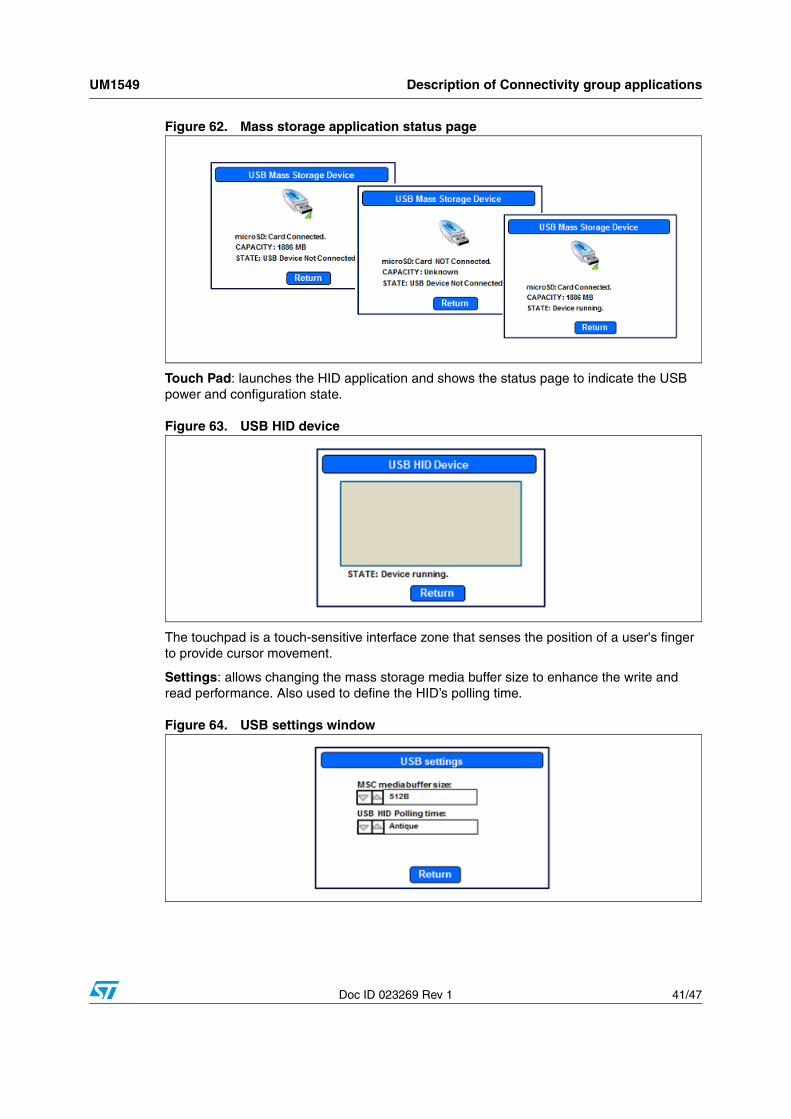
Figure 62. Mass storage application status page
Touch Pad: launches the HID application and shows the status page to indicate the USB power and configuration state.
Figure 63. USB HID device
The touchpad is a touch-sensitive interface zone that senses the position of a user's finger to provide cursor movement.
Settings: allows changing the mass storage media buffer size to enhance the write and read performance. Also used to define the HID’s polling time.
Figure 64. USB settings window
Description of Connectivity group applications UM1549
42/47 Doc ID 023269 Rev 1
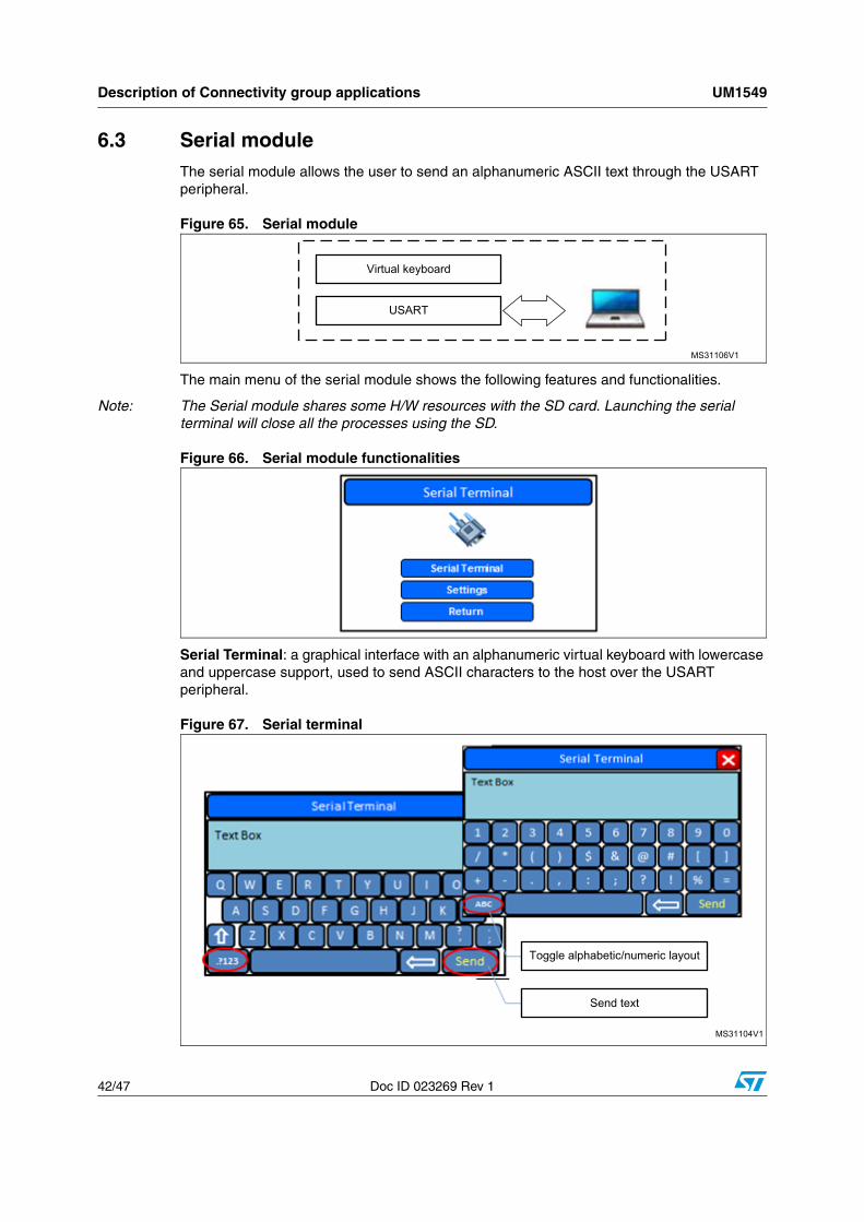
6.3 Serial moduleThe serial module allows the user to send an alphanumeric ASCII text through the USART peripheral.
Figure 65. Serial module
The main menu of the serial module shows the following features and functionalities.
Note: The Serial module shares some H/W resources with the SD card. Launching the serial terminal will close all the processes using the SD.
Figure 66. Serial module functionalities
Serial Terminal: a graphical interface with an alphanumeric virtual keyboard with lowercase and uppercase support, used to send ASCII characters to the host over the USART peripheral.
Figure 67. Serial terminal
MS31106V1
Virtual keyboard
USART
MS31104V1
Toggle alphabetic/numeric layout
Send text

UM1549 Description of Connectivity group applications
Doc ID 023269 Rev 1 43/47
Settings: used to change the configuration of the serial communication.
Figure 68. Serial settings window

Hardware configuration UM1549
44/47 Doc ID 023269 Rev 1
7 Hardware configuration
Figure 69. Hardware configuration
7.1 Required accessoriesIn addition to the STM32xxG-EVAL board, the Demonstration Builder requires the following accessories (provided with the EVAL board package):
● USB Flash disk.
● MicroSD card.
● Headphones with male jack connector.
● Micro-AB to standard receptacle A connector.
● Micro-AB to standard plug A connector.
MS31105V1
MicroSD connector
Ethernet connector
USB FS connector
USART connector
ST Link/USB connector
USB HS connector
JLink connector
Camera
QVGA display 320 x 240 +
resistive touchscreen

UM1549 Hardware configuration
Doc ID 023269 Rev 1 45/47
7.2 Jumper configuration
Table 3. Configuring the jumpers
Jumper Usage Configuration Note
JP5 Ethernet 2 <->3 25 MHz clock provided by MCO
JP6 Ethernet 2 <->3 MII interface mode enabled
JP8 Ethernet Open MII interface mode enabled
JP16 microSD 1 <->2
JP19 RTC 2 <->3 RTC powered by embedded battery
JP31 USB OTG HS Fitted USB OTG HS Selected
SW1 Boot mode 1 <->2 Boot from User Flash
SW1 Boot Mode 1 <->2 Boot from User Flash
Revision history UM1549
46/47 Doc ID 023269 Rev 1
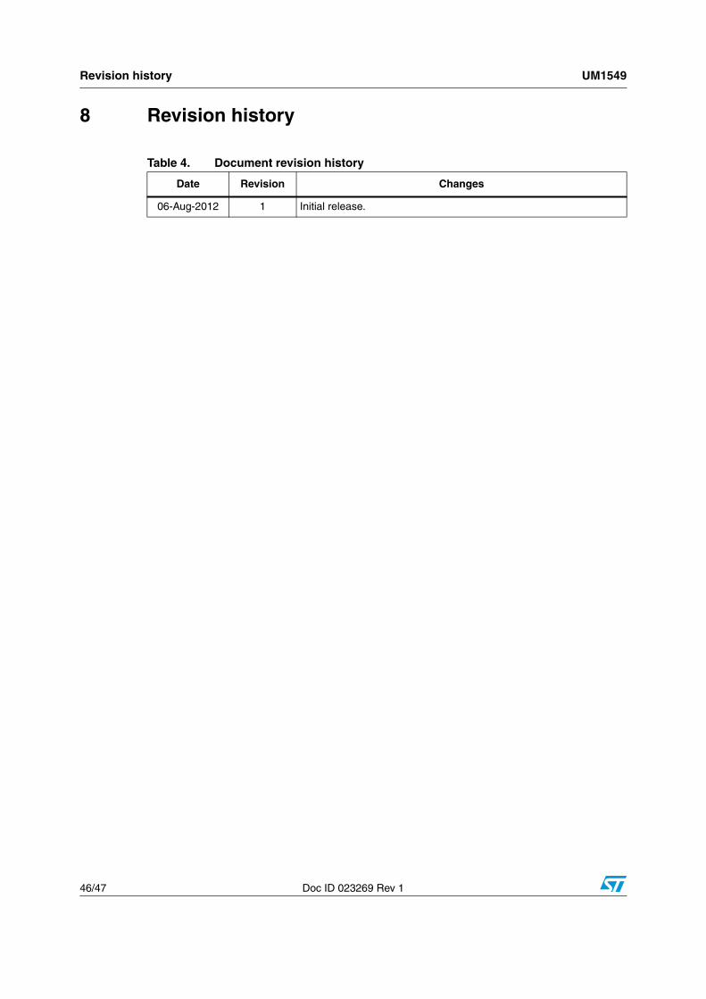
8 Revision history
Table 4. Document revision history
Date Revision Changes
06-Aug-2012 1 Initial release.
Doc ID 023269 Rev 1 47/47
Please Read Carefully:
Information in this document is provided solely in connection with ST products. STMicroelectronics NV and its subsidiaries (“ST”) reserve theright to make changes, corrections, modifications or improvements, to this document, and the products and services described herein at anytime, without notice.
All ST products are sold pursuant to ST’s terms and conditions of sale.
Purchasers are solely responsible for the choice, selection and use of the ST products and services described herein, and ST assumes noliability whatsoever relating to the choice, selection or use of the ST products and services described herein.
No license, express or implied, by estoppel or otherwise, to any intellectual property rights is granted under this document. If any part of thisdocument refers to any third party products or services it shall not be deemed a license grant by ST for the use of such third party productsor services, or any intellectual property contained therein or considered as a warranty covering the use in any manner whatsoever of suchthird party products or services or any intellectual property contained therein.
UNLESS OTHERWISE SET FORTH IN ST’S TERMS AND CONDITIONS OF SALE ST DISCLAIMS ANY EXPRESS OR IMPLIEDWARRANTY WITH RESPECT TO THE USE AND/OR SALE OF ST PRODUCTS INCLUDING WITHOUT LIMITATION IMPLIEDWARRANTIES OF MERCHANTABILITY, FITNESS FOR A PARTICULAR PURPOSE (AND THEIR EQUIVALENTS UNDER THE LAWSOF ANY JURISDICTION), OR INFRINGEMENT OF ANY PATENT, COPYRIGHT OR OTHER INTELLECTUAL PROPERTY RIGHT.
UNLESS EXPRESSLY APPROVED IN WRITING BY TWO AUTHORIZED ST REPRESENTATIVES, ST PRODUCTS ARE NOTRECOMMENDED, AUTHORIZED OR WARRANTED FOR USE IN MILITARY, AIR CRAFT, SPACE, LIFE SAVING, OR LIFE SUSTAININGAPPLICATIONS, NOR IN PRODUCTS OR SYSTEMS WHERE FAILURE OR MALFUNCTION MAY RESULT IN PERSONAL INJURY,DEATH, OR SEVERE PROPERTY OR ENVIRONMENTAL DAMAGE. ST PRODUCTS WHICH ARE NOT SPECIFIED AS "AUTOMOTIVEGRADE" MAY ONLY BE USED IN AUTOMOTIVE APPLICATIONS AT USER’S OWN RISK.
Resale of ST products with provisions different from the statements and/or technical features set forth in this document shall immediately voidany warranty granted by ST for the ST product or service described herein and shall not create or extend in any manner whatsoever, anyliability of ST.
ST and the ST logo are trademarks or registered trademarks of ST in various countries.
Information in this document supersedes and replaces all information previously supplied.
The ST logo is a registered trademark of STMicroelectronics. All other names are the property of their respective owners.
© 2012 STMicroelectronics - All rights reserved
STMicroelectronics group of companies
Australia - Belgium - Brazil - Canada - China - Czech Republic - Finland - France - Germany - Hong Kong - India - Israel - Italy - Japan - Malaysia - Malta - Morocco - Philippines - Singapore - Spain - Sweden - Switzerland - United Kingdom - United States of America
www.st.com