ultrasonic water meter qalcosonic flow … · ultrasonic water meter qalcosonic flow 4 technical...
TRANSCRIPT
AKCINĖ BENDROVĖ “AXIS INDUSTRIES”
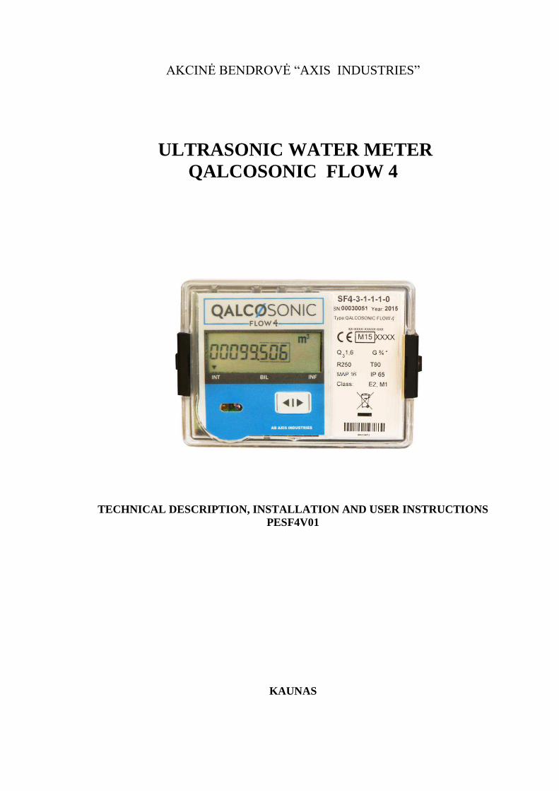
ULTRASONIC WATER METER
QALCOSONIC FLOW 4
TECHNICAL DESCRIPTION, INSTALLATION AND USER INSTRUCTIONS PESF4V01
KAUNAS
PESF4V01 2015 09 08 2
Content SAFETY INFORMATION............................................................................................................ 1. APPLICATION FIELD................................................................................................................. 2. TECHNICAL DATA..................................................................................................................... 3. OPERATION PRINCIPLE............................................................................................................ 4. MARKING AND SEALING......................................................................................................... 5. INSTALLATION........................................................................................................................... 6. OPERATION................................................................................................................................. 7.VERIFICATION............................................................................................................................. 8. TRANSPORTATION AND STORAGE......................................... ............................................. 9. WARRANTY................................................................................................................................. Annex A.Wiring diagram.................................................................................................................... Annex B. Sizes and dimensions.......................................................................................................... Annex C. Sealing diagrams and mounting recommendations...........................................................
Page 3 3
3 5 8 8 9 12 19 19 20 21 23 29
EC DECLARATION OF CONFORMITY
AB „Axis Industries“ herewith declares, that this product complies with the relevant requirements of the following directives:
- 2004/22/EC Measuring instruments Directive - 2004/108/EC EMC Directive - 2006/95/EC Low voltage Directive
Kaunas, 2016-01-12
EC-type examination certificate: LT-1621-MI001-019
For EU Customers only - WEEE Marking. Marking of electrical and electronic equipment in accordance with Article 11 (2) of Directive 2002/96/EC
This symbol on the product indicates that it will not be treated as household waste. It must be handed over to the applicable take-back scheme for the recycling of electrical and electronic equipment. For more detailed information about the recycling of this product, please contact your local municipal office.
PESF4V01 2015 09 08 3
SAFETY INFORMATION Before beginning installation works you must to read this document and follow its instructions.
The meter is powered from the battery (3.6 V), risk factors during the meter installation and service fluid flowing within flow sensor with inner pressure up to 2,5 MPa and temperature up to 90 0C.
Only qualified technical personnel may install and maintain water meters. Personnel must be familiar with appropriate technical documentation and general safety instructions. It is necessary to follow general safety requirements during installation and maintenance process.
Safety guarantees at installation and service of meter is: - Reliable insulation of electrical circuits, - Hermetic fitting of primary flow and temperature sensors into the pipeline, - Reliable fastening of water meter at installation. Warning! Mounting of the sub-assemblies of water meter is permissible only after
ensuring of absence of fluid and pressure in the pipeline.
Caution: If this equipment is used in a manner not specified by the manufacturer, the protection provided by the equipment may be impaired.
The meter can be used: - when ambient temperature is from +5 oC to +65 oC, - relative humidity up to 98 %.
1. APPLICATION FIELD
Ultrasonic water meter QALCOSONIC FLOW 4 is desighed for measurement of cold and hot water consumption in households and blocks of flats well as industry.
The meter corresponds to essential requirements of the Technical Regulation requirements Annexes I and MI 001. The meter complies with the requirements of European Standards EN 14154, EN ISO 4064 and requirements of OIML R49-1.
PESF4V01 2015 09 08 4
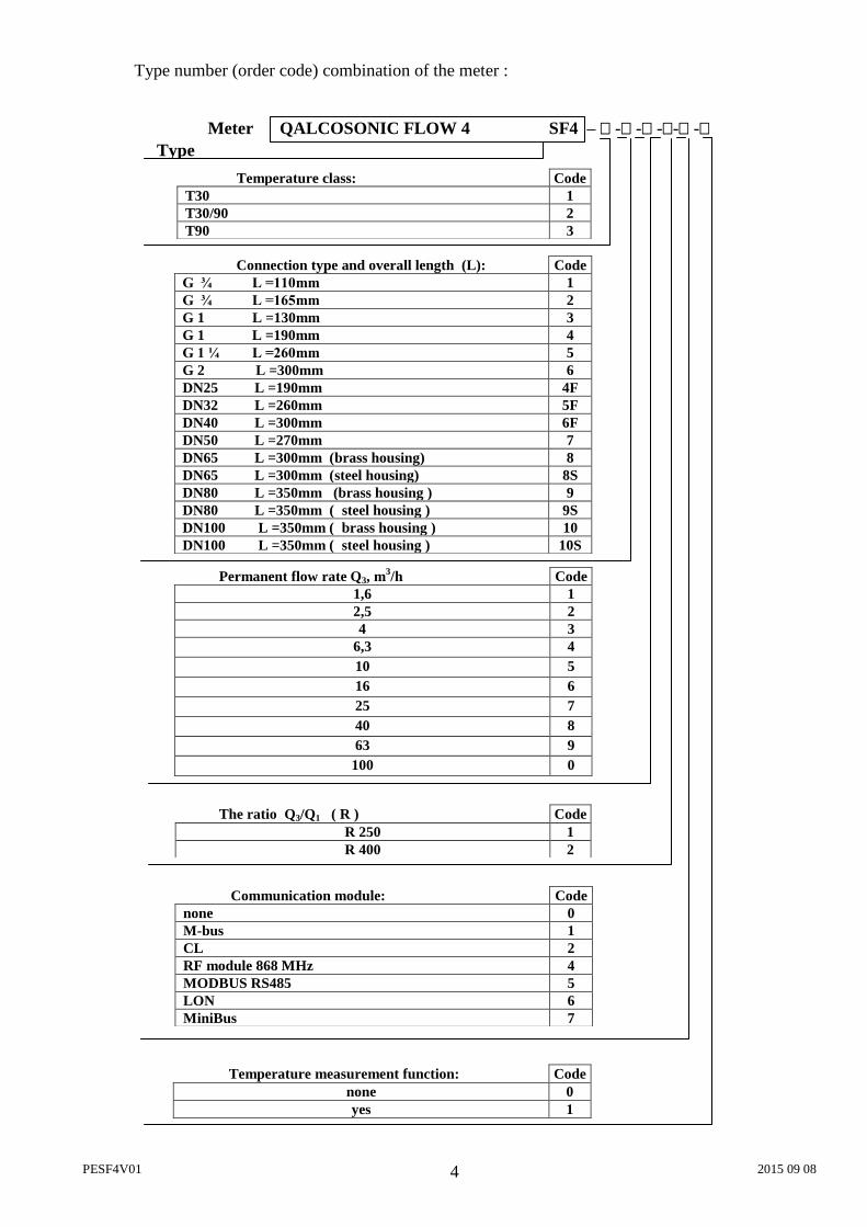
Type number (order code) combination of the meter :
Temperature class: Code T30 1 T30/90 2 T90 3
Connection type and overall length (L): Code G ¾ L =110mm 1 G ¾ L =165mm 2 G 1 L =130mm 3 G 1 L =190mm 4 G 1 ¼ L =260mm 5 G 2 L =300mm 6 DN25 L =190mm 4F DN32 L =260mm 5F DN40 L =300mm 6F DN50 L =270mm 7 DN65 L =300mm (brass housing) 8 DN65 L =300mm (steel housing) 8S DN80 L =350mm (brass housing ) 9 DN80 L =350mm ( steel housing ) 9S DN100 L =350mm ( brass housing ) 10 DN100 L =350mm ( steel housing ) 10S
Communication module: Code none 0 M-bus 1 CL 2 RF module 868 MHz 4 MODBUS RS485 5 LON 6 MiniBus 7
Type
Meter QALCOSONIC FLOW 4 SF4 – - - -- -
The ratio Q3/Q1 ( R ) Code
R 250 1 R 400 2
Permanent flow rate Q3, m3/h Code
1,6 1 2,5 2 4 3
6,3 4 10 5 16 6 25 7 40 8 63 9
100 0
Temperature measurement function: Code
none 0 yes 1
PESF4V01 2015 09 08 5
2. TECHNICAL DATA
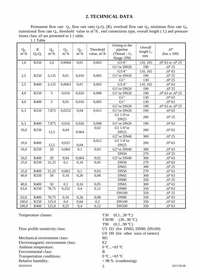
Permanent flow rate Q3, flow rate ratio Q3/Q1 (R), overload flow rate Q4, minimum flow rate Q1, transitional flow rate Q2, threshold value in m3/h , end connections type, overall length ( L) and pressure losses class ΔP are presented in 1.1 table.
1.1 Table
Q3, m3/h
R Q3/Q1
Q4, m3/h
Q1, m3/h
Q2, m3/h
Threshold value, m3/h
Joining to the pipeline
(Thread – G, flange–DN)
Overall length L,
mm
ΔP (bar x 100)
1,6 R250 2,0 0,0064 0,01 0,003 G3/4“ 110, 165 ΔP 63 or ΔP 25 G1“or DN20 190 ΔP 25 G3/4“ 110, 165 ΔP 63
2,5 R250 3,125 0,01 0,016 0,005 G1“or DN20 190 ΔP 25 G1“ 130 ΔP 25
2,5 R400 3,125 0,0063 0,01 0,003 G3/4“ 110, 165 ΔP 63 G1“or DN20 190 ΔP 25
4,0 R250 5 0,016 0,026 0,008 G1“or DN20 190 ΔP 63 or ΔP 25 G1“ 130 ΔP 63
4,0 R400 5 0,01 0,016 0,005 G1“ 130 ΔP 63 G1“or DN20 190 ΔP 63 or ΔP 25
6,3 R250 7,875 0,0252 0,04 0,012 G1“or DN20 190 ΔP 63
G1 1/4“or DN25
260 ΔP 25
6,3 R400 7,875 0,016 0,026 0,008 G1“or DN20 190 ΔP 63
10,0 R250 12,5
0,04 0,064
0,02 G1 1/4“or DN25
260 ΔP 63
G2“or DN40 300 ΔP 25
10,0 R400 12,5
0,025 0,04
0,012 G1 1/4“or DN25
260 ΔP 63
16,0 R250 20 0,064 0,1 0,03 G2“or DN40 300 ΔP 63 DN50 270 ΔP 25
16,0 R400 20 0,04 0,064 0,02 G2“or DN40 300 ΔP 63 25,0 R250 31,25 0,1 0,16 0,05 DN50 270 ΔP 63
DN65 300 ΔP 25 25,0 R400 31,25 0,063 0,1 0,03 DN50 270 ΔP 63 40,0 R250 50 0,16 0,26 0,08 DN65 300 ΔP 63
DN80 350 ΔP 25 40,0 R400 50 0,1 0,16 0,05 DN65 300 ΔP 63 63,0 R250 78,75 0,252 0,4 0,12 DN80 350 ΔP 63
DN100 350 ΔP 25 63,0 R400 78,75 0,16 0,26 0,08 DN80 350 ΔP 63 100,0 R250 125,0 0,4 0,64 0,2 DN100 350 ΔP 63 100,0 R400 125,0 0,25 0,4 0,12 DN100 350 ΔP 63 Temperature classes: T30 (0,1...30 ºC)
T30/90 (30...90 ºC) T90 (0,1...90 ºC)
Flow profile sensitivity class: U5 D3 (for DN65, DN80, DN100) U0 D0 (for other sizes of meters) Mechanical environment class: M1 Electromagnetic environment class: E2 Ambient temperature: 0 ºC...+65 ºC Environmental class: B Transportation conditions: 0 ºC...+65 ºC Relative humidity: < 98 % (condensing)
PESF4V01 2015 09 08 6
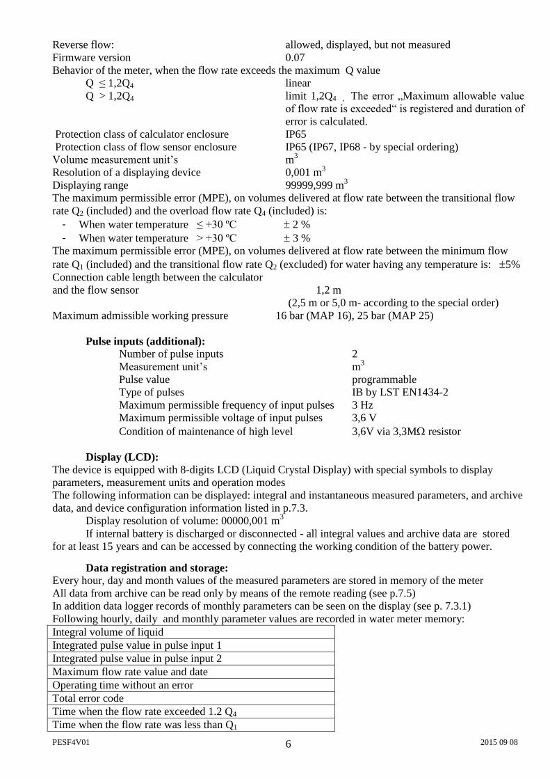
Reverse flow: allowed, displayed, but not measured Firmware version 0.07 Behavior of the meter, when the flow rate exceeds the maximum Q value Q ≤ 1,2Q4 linear
Q > 1,2Q4 limit 1,2Q4 , The error „Maximum allowable value of flow rate is exceeded“ is registered and duration of error is calculated.
Protection class of calculator enclosure IP65 Protection class of flow sensor enclosure IP65 (IP67, IP68 - by special ordering) Volume measurement unit’s m3
Resolution of a displaying device 0,001 m3
Displaying range 99999,999 m3
The maximum permissible error (MPE), on volumes delivered at flow rate between the transitional flow rate Q2 (included) and the overload flow rate Q4 (included) is:
- When water temperature ≤ +30 ºC 2 % - When water temperature > +30 ºC 3 %
The maximum permissible error (MPE), on volumes delivered at flow rate between the minimum flow rate Q1 (included) and the transitional flow rate Q2 (excluded) for water having any temperature is: 5% Connection cable length between the calculator and the flow sensor 1,2 m
(2,5 m or 5,0 m- according to the special order) Maximum admissible working pressure 16 bar (MAP 16), 25 bar (MAP 25)
Pulse inputs (additional): Number of pulse inputs 2 Measurement unit’s m3
Pulse value programmable Type of pulses IB by LST EN1434-2 Maximum permissible frequency of input pulses 3 Hz Maximum permissible voltage of input pulses 3,6 V
Condition of maintenance of high level 3,6V via 3,3Mresistor
Display (LCD): The device is equipped with 8-digits LCD (Liquid Crystal Display) with special symbols to display parameters, measurement units and operation modes The following information can be displayed: integral and instantaneous measured parameters, and archive data, and device configuration information listed in p.7.3.
Display resolution of volume: 00000,001 m3
If internal battery is discharged or disconnected - all integral values and archive data are stored for at least 15 years and can be accessed by connecting the working condition of the battery power.
Data registration and storage: Every hour, day and month values of the measured parameters are stored in memory of the meter All data from archive can be read only by means of the remote reading (see p.7.5) In addition data logger records of monthly parameters can be seen on the display (see p. 7.3.1) Following hourly, daily and monthly parameter values are recorded in water meter memory: Integral volume of liquid Integrated pulse value in pulse input 1 Integrated pulse value in pulse input 2 Maximum flow rate value and date Operating time without an error Total error code Time when the flow rate exceeded 1.2 Q4
Time when the flow rate was less than Q1
PESF4V01 2015 09 08 7
Data logger capacity: up to 1480 h – for hourly records. up to 1130 days - for daily records, up to 36 last months - for monthly records,
Archive data storage time not less than 36 months Storage time of measured integrated parameters even if device is disconnected from power supply not less than 15 years. External communication modules and interfaces: Optical interface Integrated into the front panel of calculator. It is designed for data reading via M-bus protocol and
parameterization of the meter. The optical interface starts work (is activated) only after pressing control button and automatically
shuts down after 5 minutes, after the last pressing any button or after completing data transmission via interface.
Optional plug in communication modules: M-Bus module CL-module (Current loop) LON module MODBUS RS485 RF-module 868 MHz MiniBus module It is designed for data reading via M-bus protocol and parameterization of the meter.
If meter is powered from internal battery - the total working time of serial communication interface is limited up to 200 minutes per month ( for protection of the battery against premature discharge). Unused limit of communications are summarized. The interface is blocked after the expiration of a limit and only after change of the hour, the new time limit of communications will be given (for 16 seconds for each next hour).
Pulse outputs: 2 (OB-normal mode, OD-test mode) Type: open collector, permissible current up to 20mA, voltage up to 50V. Pulse duration: 125 ms – in the normal operating mode, 1.2 ms – in the test mode
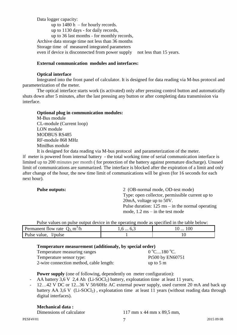
Pulse values on pulse output device in the operating mode as specified in the table below: Permanent flow rate Q3, m
3/h 1,6 ... 6,3 10 ... 100 Pulse value, l/pulse 1 10
Temperature measurement (additionaly, by special order) Temperature measuring ranges 0 oC....180 oC. Temperature sensor type: Pt500 by EN60751 2-wire connection method, cable length: up to 5 m
Power supply (one of following, dependently on meter configuration):
- AA battery 3,6 V 2,4 Ah (Li-SOCl2) battery, exploatation time at least 11 years, - 12…42 V DC or 12...36 V 50/60Hz AC external power supply, used current 20 mA and back up
battery AA 3,6 V (Li-SOCl2) , exploatation time at least 11 years (without reading data through digital interfaces).
Mechanical data : Dimensions of calculator 117 mm x 44 mm x 89,5 mm,
PESF4V01 2015 09 08 8
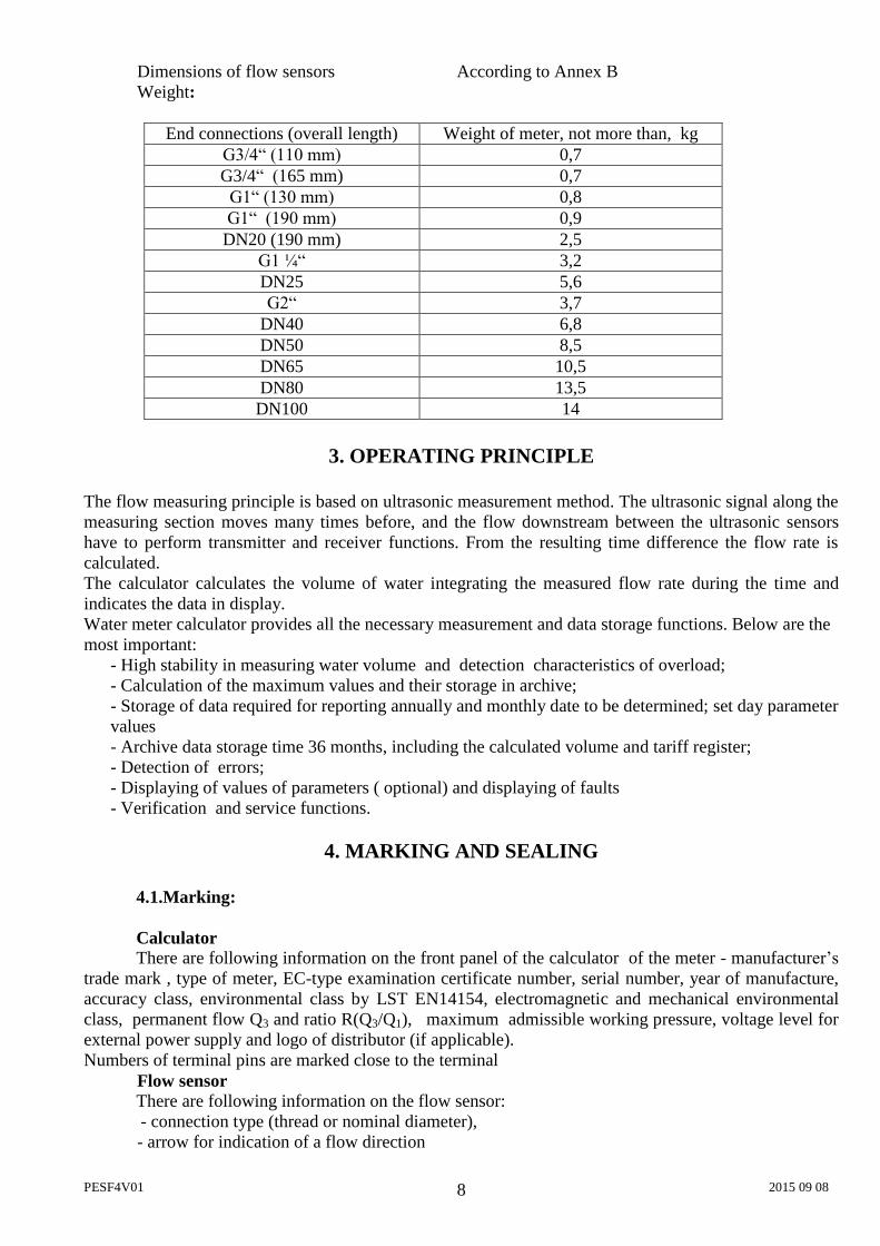
Dimensions of flow sensors According to Annex B Weight:
End connections (overall length) Weight of meter, not more than, kg G3/4“ (110 mm) 0,7 G3/4“ (165 mm) 0,7
G1“ (130 mm) 0,8 G1“ (190 mm) 0,9
DN20 (190 mm) 2,5 G1 ¼“ 3,2 DN25 5,6 G2“ 3,7
DN40 6,8 DN50 8,5 DN65 10,5 DN80 13,5 DN100 14
3. OPERATING PRINCIPLE
The flow measuring principle is based on ultrasonic measurement method. The ultrasonic signal along the measuring section moves many times before, and the flow downstream between the ultrasonic sensors have to perform transmitter and receiver functions. From the resulting time difference the flow rate is calculated. The calculator calculates the volume of water integrating the measured flow rate during the time and indicates the data in display. Water meter calculator provides all the necessary measurement and data storage functions. Below are the most important:
- High stability in measuring water volume and detection characteristics of overload; - Calculation of the maximum values and their storage in archive; - Storage of data required for reporting annually and monthly date to be determined; set day parameter values - Archive data storage time 36 months, including the calculated volume and tariff register; - Detection of errors; - Displaying of values of parameters ( optional) and displaying of faults - Verification and service functions.
4. MARKING AND SEALING
4.1.Marking: Calculator There are following information on the front panel of the calculator of the meter - manufacturer’s trade mark , type of meter, EC-type examination certificate number, serial number, year of manufacture, accuracy class, environmental class by LST EN14154, electromagnetic and mechanical environmental class, permanent flow Q3 and ratio R(Q3/Q1), maximum admissible working pressure, voltage level for external power supply and logo of distributor (if applicable). Numbers of terminal pins are marked close to the terminal Flow sensor There are following information on the flow sensor: - connection type (thread or nominal diameter), - arrow for indication of a flow direction
PESF4V01 2015 09 08 9
4.2.Security seals The following water meter calculator sealing is provided: - Manufacturer’s adhesive seal-sticker on the access to the adjustment activation jumper (see
Annex C, Fig.C1, pos.1). - Manufacturer’s adhesive seal-sticker on the fixer of the cover protecting electronic module (see Annex C, Fig.C1, pos.2). The following flow sensor sealing is provided: - Manufacturer’s adhesive seal-sticker on the bolts of protective cover of flow sensor (see Annex C, Fig.C2a;b;c). - Manufacturer’s hanged seals on ultrasonic transducers (see Annex C, Fig.C2d). Mounting seal: - After installation the case and cover of the calculator are sealed with 2 hanged seals (see Annex C, Fig.C1, pos.3) The meter must be sealed to ensure that after the installation, it is not possibility of dismantle, remove or altering the meter without evident damage on the meter or the seal.
5. INSTALLATION
5.1. Basic requirements
Before installing the device: - check if all parts listed in the documentation are available, - check if there are no visible mechanical defects, - check if there are valid labels of manufacturer and certification authority.
Only qualified personnel may install the equipment, following the requirements listed in this document, in technical documentation of other system components and in water meter installation project It is forbidden to wire signal cables nearby (less than 5 cm) with power cables or cables of other devices.
It is forbidden to change length of a cable. 5.2. Electrical wiring 5.2.1. Connection of external power supply
If the meter is with external power supply it is required to pull unused seal holes in the protective mound, put throught the cable and strengthen, as shown in Annex B in Figure B1. Connect as shown in the diagram.
5.2.2. Installation of additional communication modules In the bottom, right-hand corner of the calculator, communication module can be installed and
must by connected. Connector of the communication module is set in a calculator connector. The module is fastening with two screws. Connection of the communication module (except the module RF):
By means of tweezers remove a protective knoll from not used sealant hole of calculator Run the wire through the hole and fix as shown in chapter Annex B in Figure B1. Connect a wire
to the module under the scheme specified on the module. After that it is needed to connect the power supply into an empty battery slot and battery holder. It is prohibited to mont the signal lines near (less than 5 cm) power cables or other devices cables.
PESF4V01 2015 09 08 10
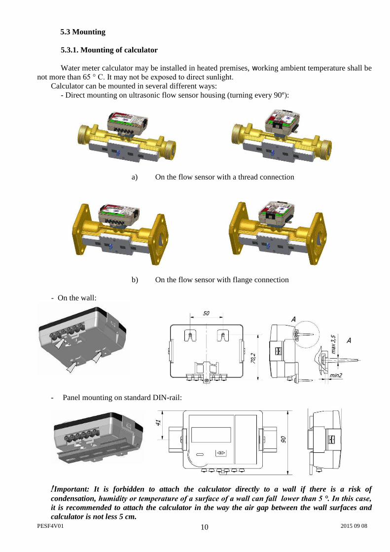
5.3 Mounting 5.3.1. Mounting of calculator
Water meter calculator may be installed in heated premises, working ambient temperature shall be not more than 65 ° C. It may not be exposed to direct sunlight.
Calculator can be mounted in several different ways: - Direct mounting on ultrasonic flow sensor housing (turning every 90º):
a) On the flow sensor with a thread connection
b) On the flow sensor with flange connection - On the wall:
- Panel mounting on standard DIN-rail:
Important: It is forbidden to attach the calculator directly to a wall if there is a risk of condensation, humidity or temperature of a surface of a wall can fall lower than 5 °. In this case, it is recommended to attach the calculator in the way the air gap between the wall surfaces and calculator is not less 5 cm.
PESF4V01 2015 09 08 11
5.3.2. Mounting of flow sensors
Sizes and mounting dimensions of flow sensors are provided in Annex B. Requirements for flow sensor installation in pipeline:
- For water meters with flow sensors DN65…DN100 necessary straight pipelines lengths are: upstream straight pipeline length must be not less 5DN and downstream straight pipeline length must be not less 3DN ( flow profile sensitivity class U5 D3) - For water meters of other sizes no requirements for straight pipeline length in upstream and downstream directions ( flow profile sensitivity class U0 D0)
Avoid the flow sensor installation near after the pumps which can cause cavitations. Flow sensor can be mounted both vertically and horizontally in pipelines or on an incline.
If flow direction in the pipeline is from top to down, the pipeline must be under pressure. The direction of the sensor installation (is indicated with the arrow on flow sensor) must match with the flow direction in pipeline.
The flange gaskets must match with the pipe diameter. During the installation gasket must be exactly centered with the center of the pipe cross-section to avoid sticking out gaskets inside the pipe. 5.4. Setting up the jumpers (J)
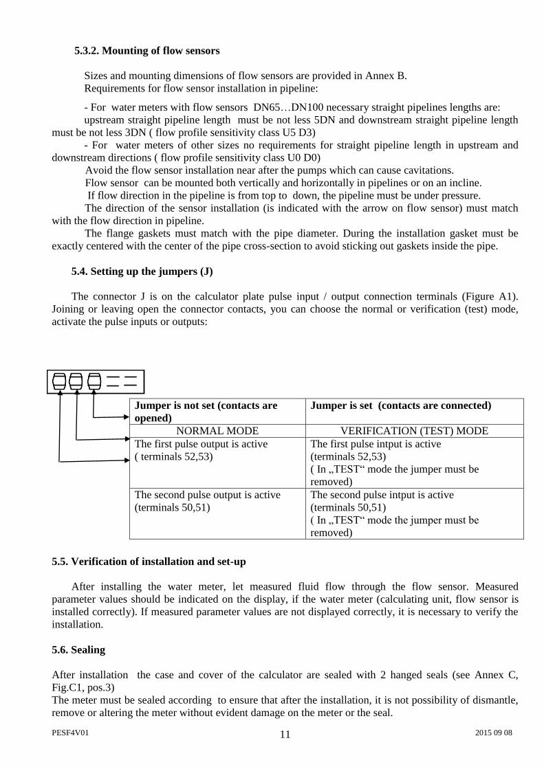
The connector J is on the calculator plate pulse input / output connection terminals (Figure A1). Joining or leaving open the connector contacts, you can choose the normal or verification (test) mode, activate the pulse inputs or outputs: 5.5. Verification of installation and set-up After installing the water meter, let measured fluid flow through the flow sensor. Measured parameter values should be indicated on the display, if the water meter (calculating unit, flow sensor is installed correctly). If measured parameter values are not displayed correctly, it is necessary to verify the installation. 5.6. Sealing
After installation the case and cover of the calculator are sealed with 2 hanged seals (see Annex C, Fig.C1, pos.3) The meter must be sealed according to ensure that after the installation, it is not possibility of dismantle, remove or altering the meter without evident damage on the meter or the seal.
Jumper is not set (contacts are opened)
Jumper is set (contacts are connected)
NORMAL MODE VERIFICATION (TEST) MODE The first pulse output is active ( terminals 52,53)
The first pulse intput is active (terminals 52,53) ( In „TEST“ mode the jumper must be removed)
The second pulse output is active (terminals 50,51)
The second pulse intput is active (terminals 50,51) ( In „TEST“ mode the jumper must be removed)
PESF4V01 2015 09 08 12
6. OPERATION
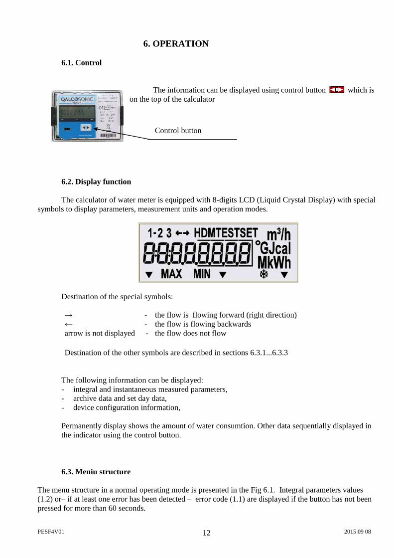
6.1. Control
The information can be displayed using control button which is on the top of the calculator
6.2. Display function The calculator of water meter is equipped with 8-digits LCD (Liquid Crystal Display) with special
symbols to display parameters, measurement units and operation modes.
Destination of the special symbols: → - the flow is flowing forward (right direction) ← - the flow is flowing backwards arrow is not displayed - the flow does not flow Destination of the other symbols are described in sections 6.3.1...6.3.3
The following information can be displayed: - integral and instantaneous measured parameters, - archive data and set day data, - device configuration information,
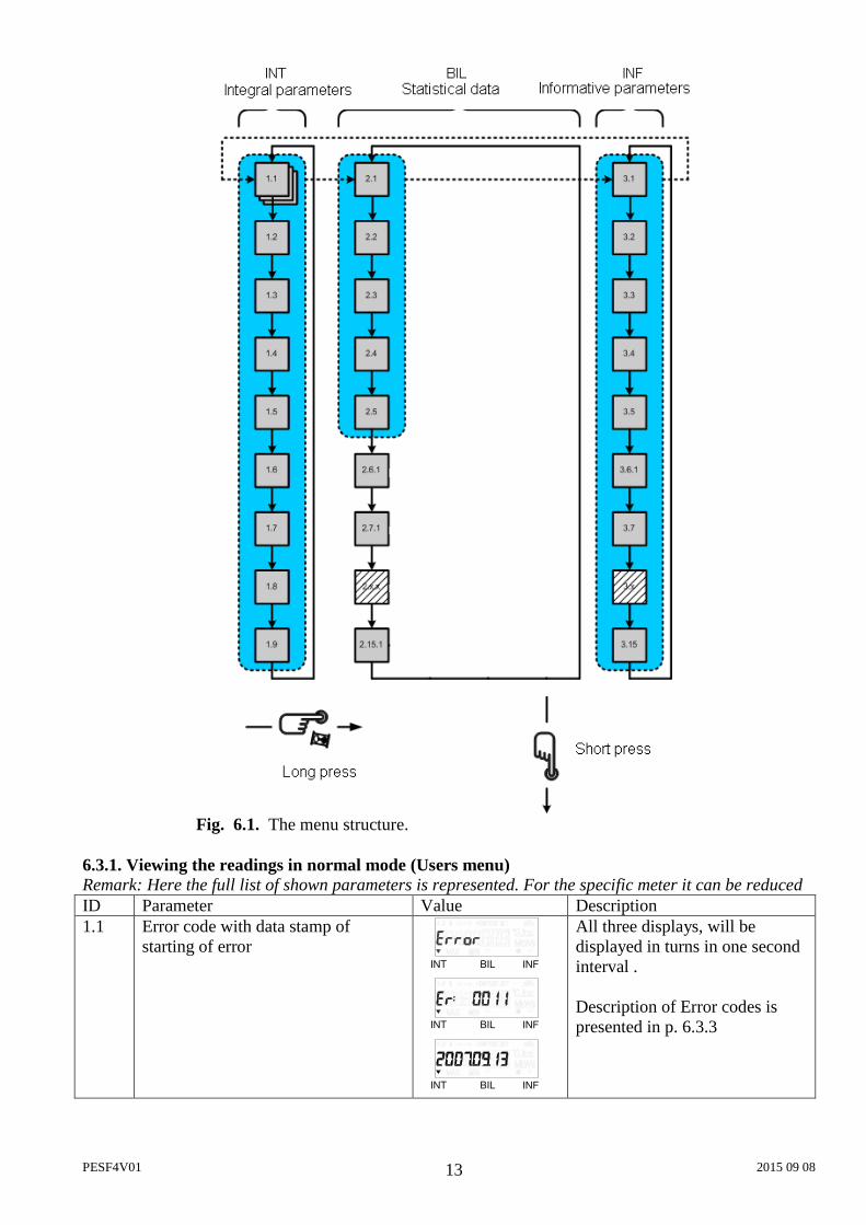
Permanently display shows the amount of water consumtion. Other data sequentially displayed in the indicator using the control button. 6.3. Meniu structure
The menu structure in a normal operating mode is presented in the Fig 6.1. Integral parameters values (1.2) or– if at least one error has been detected – error code (1.1) are displayed if the button has not been pressed for more than 60 seconds.
Control button
PESF4V01 2015 09 08 13
Fig. 6.1. The menu structure. 6.3.1. Viewing the readings in normal mode (Users menu) Remark: Here the full list of shown parameters is represented. For the specific meter it can be reduced ID Parameter Value Description 1.1 Error code with data stamp of
starting of error INT INFBIL
INT INFBIL
INT INFBIL
All three displays, will be displayed in turns in one second interval . Description of Error codes is presented in p. 6.3.3
PESF4V01 2015 09 08 14
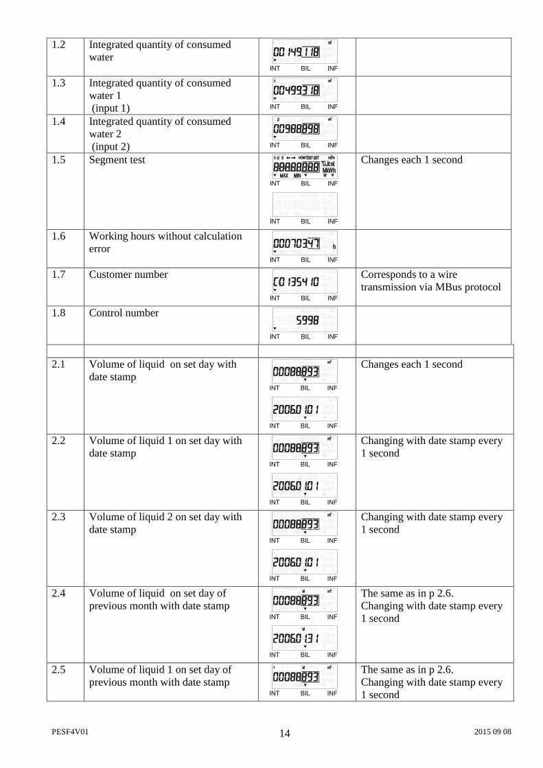
1.2 Integrated quantity of consumed water
INT INFBIL
1.3 Integrated quantity of consumed water 1 (input 1) INT INFBIL
1.4 Integrated quantity of consumed water 2 (input 2) INT INFBIL
1.5 Segment test
INT INFBIL
INT INFBIL
Changes each 1 second
1.6 Working hours without calculation error
INT INFBIL
1.7 Customer number
INT INFBIL
Corresponds to a wire transmission via MBus protocol
1.8 Control number
INT INFBIL
2.1 Volume of liquid on set day with
date stamp INT INFBIL
INT INFBIL
Changes each 1 second
2.2 Volume of liquid 1 on set day with date stamp
INT INFBIL
INT INFBIL
Changing with date stamp every 1 second
2.3 Volume of liquid 2 on set day with date stamp
INT INFBIL
INT INFBIL
Changing with date stamp every 1 second
2.4
Volume of liquid on set day of previous month with date stamp
INT INFBIL
INT INFBIL
The same as in p 2.6. Changing with date stamp every 1 second
2.5
Volume of liquid 1 on set day of previous month with date stamp
INT INFBIL
The same as in p 2.6. Changing with date stamp every 1 second
PESF4V01 2015 09 08 15
INT INFBIL 2.6
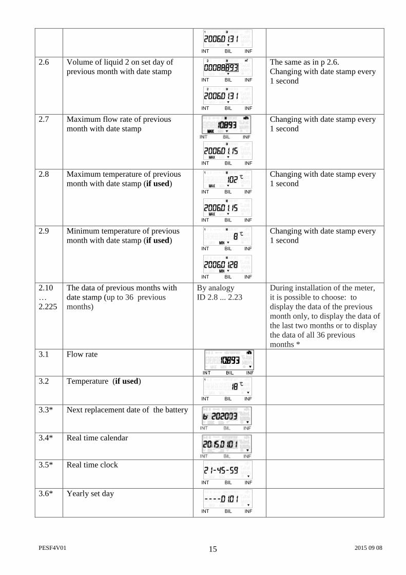
Volume of liquid 2 on set day of previous month with date stamp
INT INFBIL
INT INFBIL
The same as in p 2.6. Changing with date stamp every 1 second
2.7
Maximum flow rate of previous month with date stamp
INT INFBIL
Changing with date stamp every 1 second
2.8
Maximum temperature of previous month with date stamp (if used) INT INFBIL
INT INFBIL
Changing with date stamp every 1 second
2.9
Minimum temperature of previous month with date stamp (if used) INT INFBIL
INT INFBIL
Changing with date stamp every 1 second
2.10… 2.225
The data of previous months with date stamp (up to 36 previous months)
By analogy ID 2.8 ... 2.23
During installation of the meter, it is possible to choose: to display the data of the previous month only, to display the data of the last two months or to display the data of all 36 previous months *
3.1 Flow rate
3.2 Temperature (if used)
INT INFBIL
3.3* Next replacement date of the battery
3.4* Real time calendar
3.5* Real time clock
INT INFBIL
3.6* Yearly set day
INT INFBIL
PESF4V01 2015 09 08 16
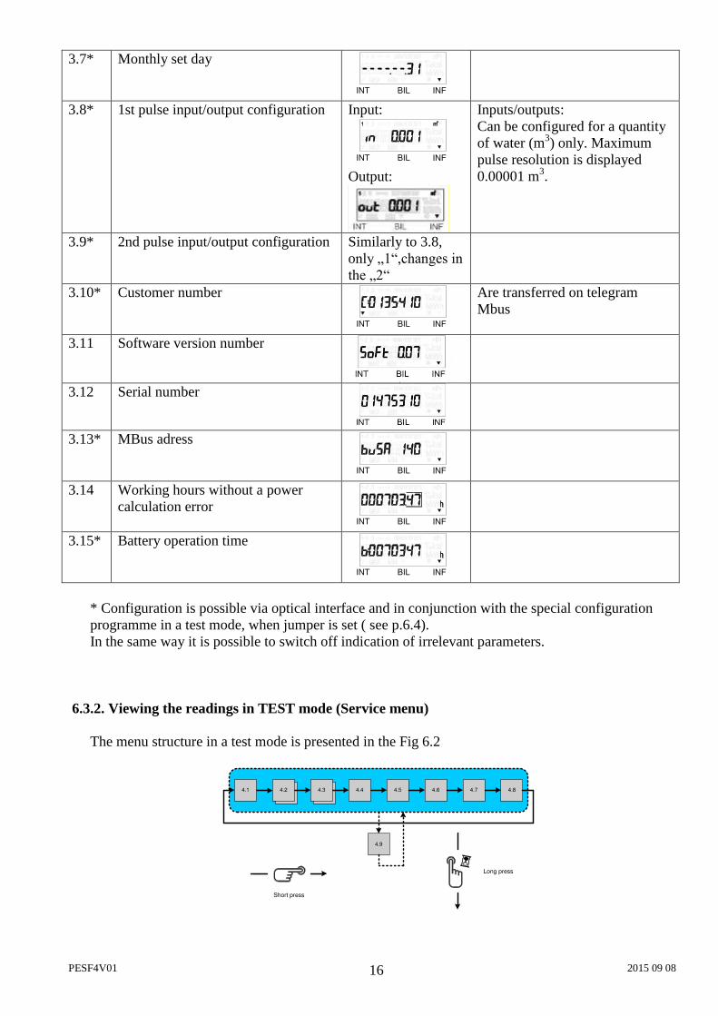
3.7* Monthly set day
INT INFBIL
3.8* 1st pulse input/output configuration Input:
INT INFBIL Output:
Inputs/outputs: Can be configured for a quantity of water (m3) only. Maximum pulse resolution is displayed 0.00001 m3.
3.9* 2nd pulse input/output configuration Similarly to 3.8, only „1“,changes in the „2“
3.10* Customer number
INT INFBIL
Are transferred on telegram Mbus
3.11 Software version number
3.12 Serial number
3.13* MBus adress
INT INFBIL
3.14 Working hours without a power calculation error
INT INFBIL
3.15* Battery operation time
INT INFBIL
* Configuration is possible via optical interface and in conjunction with the special configuration programme in a test mode, when jumper is set ( see p.6.4). In the same way it is possible to switch off indication of irrelevant parameters.
6.3.2. Viewing the readings in TEST mode (Service menu) The menu structure in a test mode is presented in the Fig 6.2
4.54.4 4.6 4.7 4.84.1 4.34.2
4.9
Short press
Long press
PESF4V01 2015 09 08 17
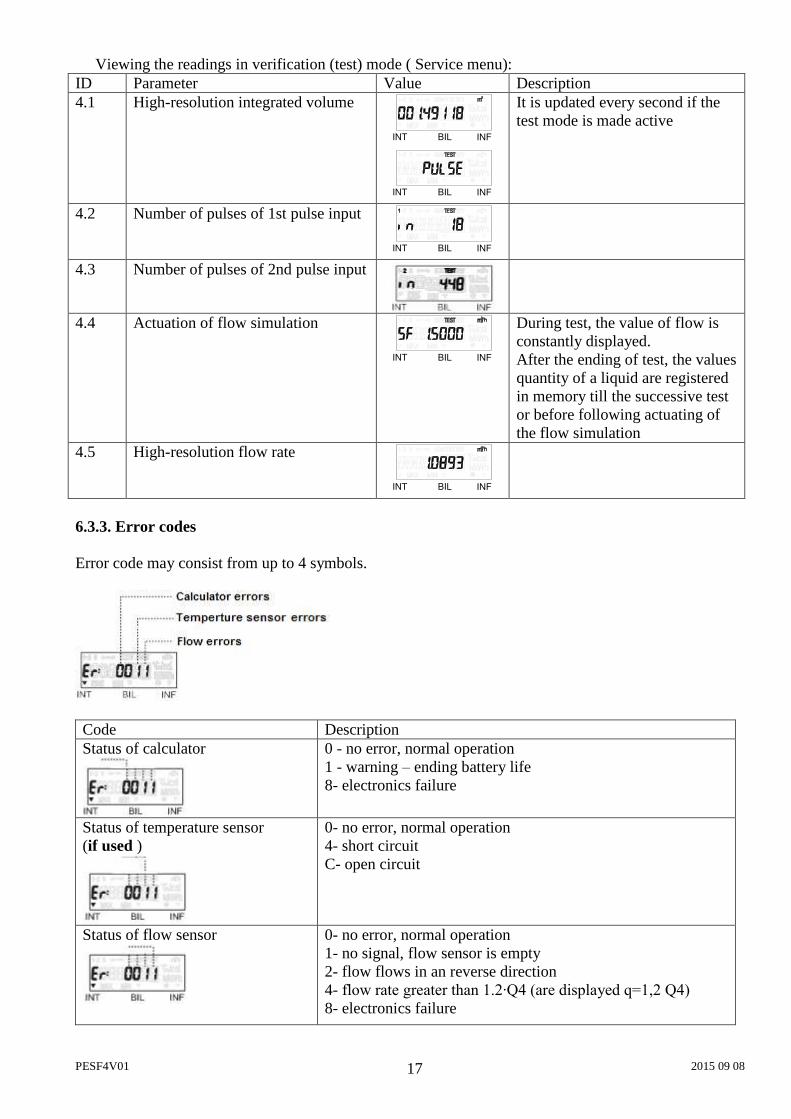
Viewing the readings in verification (test) mode ( Service menu): ID Parameter Value Description 4.1 High-resolution integrated volume
INT INFBIL
INT INFBIL
It is updated every second if the test mode is made active
4.2 Number of pulses of 1st pulse input
INT INFBIL
4.3 Number of pulses of 2nd pulse input
4.4 Actuation of flow simulation
INT INFBIL
During test, the value of flow is constantly displayed. After the ending of test, the values quantity of a liquid are registered in memory till the successive test or before following actuating of the flow simulation
4.5 High-resolution flow rate
INT INFBIL
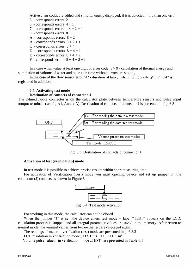
6.3.3. Error codes Error code may consist from up to 4 symbols.
Code Description Status of calculator
0 - no error, normal operation 1 - warning – ending battery life 8- electronics failure
Status of temperature sensor (if used )
0- no error, normal operation 4- short circuit C- open circuit
Status of flow sensor
0- no error, normal operation 1- no signal, flow sensor is empty 2- flow flows in an reverse direction 4- flow rate greater than 1.2∙Q4 (are displayed q=1,2 Q4) 8- electronics failure
PESF4V01 2015 09 08 18
Active error codes are added and simultaneously displayed, if it is detected more than one error 3 - corresponds errors 2 + 1 5 - corresponds errors 4 + 1 7 - corresponds errors 4 + 2 + 1 9 - corresponds errors 8 + 1 A - corresponds errors 8 + 2 B - corresponds errors 8 + 2 + 1 C - corresponds errors 8 + 4 D - corresponds errors 8 + 4 + 1 E - corresponds errors 8 + 4 + 2 F - corresponds errors 8 + 4 + 2 +1 In a case when value at least one digit of error code is ≥ 8 - calculation of thermal energy and
summation of volume of water and operation time without errors are stoping In the case of the flow sensor error "4" - duration of time, "when the flow rate q> 1.2 ∙ Q4" is
registered in addition.
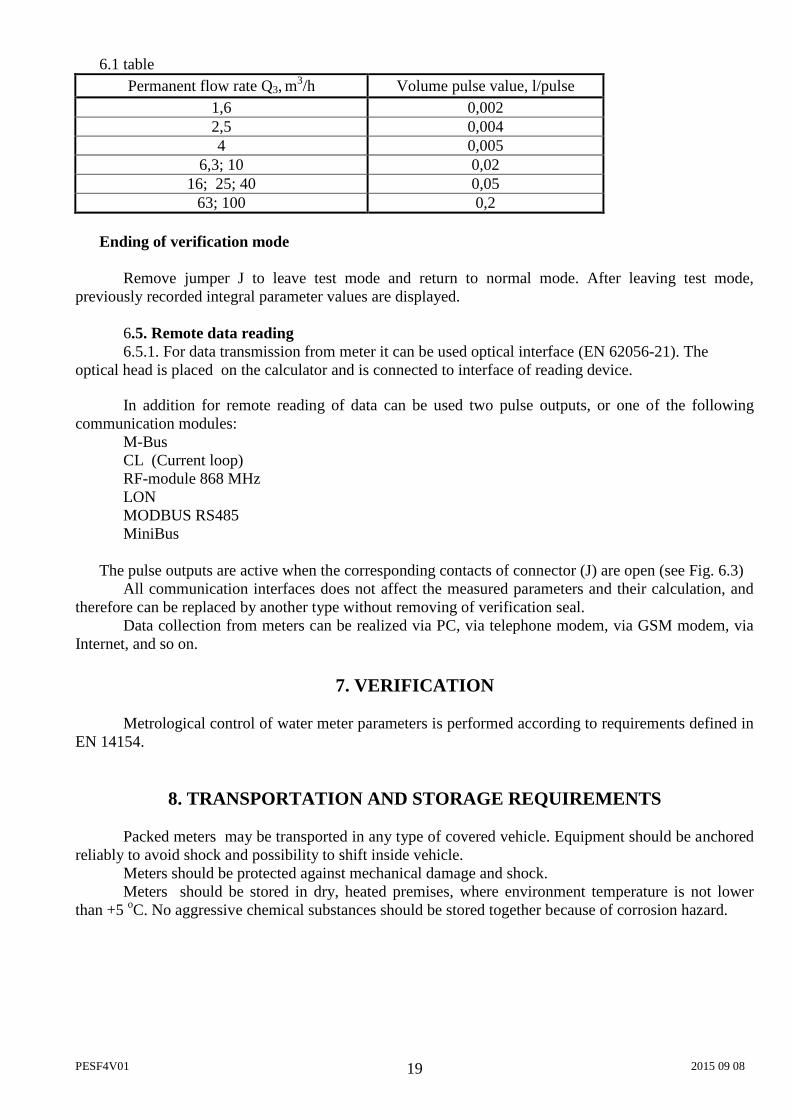
6.4. Activating test mode Destination of contacts of connector J
The 2-line,10-pole connector is on the calculator plate between temperature sensors and pulse input /output terminals (see fig.A1, Annex A). Destination of contacts of connector J is presented in fig. 6.3.
Fig. 6.3. Destination of contacts of connector J Activation of test (verification) mode In test mode it is possible to achieve precise results within short measuring time. For activation of Verification (Test) mode you must opening device and set up jumper on the
connector (J) contacts as shown in Figure 6.4.
Fig. 6.4. Test mode activation For working in this mode, the calculator can not be closed. When the jumper “J” is set, the device enters test mode – label “TEST” appears on the LCD,
calculation process is stopped and all integral parameter values are saved in the memory. After return to normal mode, the original values from before the test are displayed again.
The readings of meter in verification (test) mode are presented in p. 6.3.2 LCD resolution in verification mode „TEST“ is 00,000001 m3
Volume pulse values in verification mode „TEST“ are presented in Table 6.1
PESF4V01 2015 09 08 19
6.1 table Permanent flow rate Q3, m
3/h Volume pulse value, l/pulse 1,6 0,002 2,5 0,004 4 0,005
6,3; 10 0,02 16; 25; 40 0,05
63; 100 0,2 Ending of verification mode
Remove jumper J to leave test mode and return to normal mode. After leaving test mode, previously recorded integral parameter values are displayed.
6.5. Remote data reading
6.5.1. For data transmission from meter it can be used optical interface (EN 62056-21). The optical head is placed on the calculator and is connected to interface of reading device.
In addition for remote reading of data can be used two pulse outputs, or one of the following
communication modules: M-Bus CL (Current loop) RF-module 868 MHz LON MODBUS RS485 MiniBus
The pulse outputs are active when the corresponding contacts of connector (J) are open (see Fig. 6.3) All communication interfaces does not affect the measured parameters and their calculation, and
therefore can be replaced by another type without removing of verification seal. Data collection from meters can be realized via PC, via telephone modem, via GSM modem, via
Internet, and so on.
7. VERIFICATION
Metrological control of water meter parameters is performed according to requirements defined in EN 14154.
8. TRANSPORTATION AND STORAGE REQUIREMENTS
Packed meters may be transported in any type of covered vehicle. Equipment should be anchored reliably to avoid shock and possibility to shift inside vehicle. Meters should be protected against mechanical damage and shock. Meters should be stored in dry, heated premises, where environment temperature is not lower than +5 oC. No aggressive chemical substances should be stored together because of corrosion hazard.

PESF4V01 2015 09 08 20
9. WARRANTY
Manufacturer gives the warranty that meter parameters will meet the technical requirements, listed in the paragraph 2 of this document, if transportation, storage and operation conditions will be followed. Warranty period - 12 months from bringing into operation, but not more than 18 months from manufacturing date. Manufacturer’s address:
AB “Axis Industries ”, Kulautuvos g. 45a, Kaunas LT-47190, Lithuania tel. +370 37 360234; fax. +370 37 360358.
Annex A
PESF4V01 2015 09 08 21
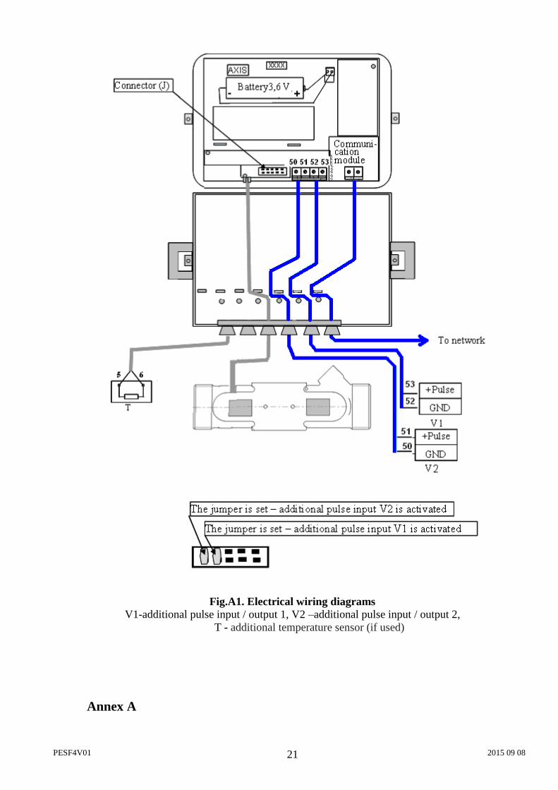
Fig.A1. Electrical wiring diagrams V1-additional pulse input / output 1, V2 –additional pulse input / output 2,
T - additional temperature sensor (if used) Annex A

PESF4V01 2015 09 08 22
A2 fig. External power supply electrical wiring diagram
A1 table. Numbering of terminals
Terminal no: Description 50 2nd additionl pulse input/output GND 51 2nd additionl pulse input/output (In/Out2)
(Volume output for TEST mode) 52 1st additionl pulse input/output GND 53 1st additionl pulse input/output (In/Out1) 5 Terminal for temperature sensor (If temperature sensor is used) 6 Terminal for temperature sensor (If temperature sensor is used)
Terminal no: Description 20 CL+ (CL module) 21 CL- (CL module)
24, 25 M-bus (Mbus module) 51 MiniBus module + line terminal 52 MiniBus module – line terminal
60, 61 MODBUS and LON module 12-24 V DC power supply 90 MODBUS module + terminal 91 MODBUS module - terminal 96 LON module A terminal 97 LON module B terminal
Terminal no: Description 54 External power supply (24 V AC/DC) terminal 55 External power supply (24 V AC/DC) terminal
ANNEX B
PESF4V01 2015 09 08 23
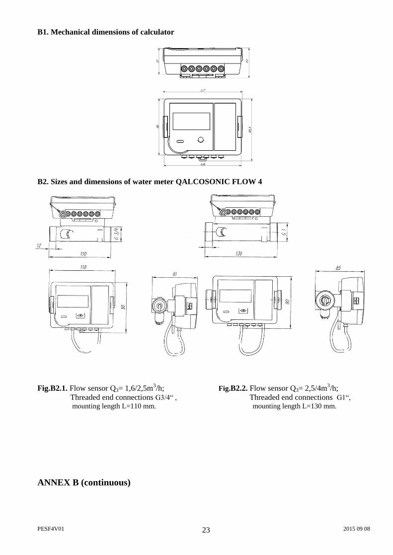
B1. Mechanical dimensions of calculator
B2. Sizes and dimensions of water meter QALCOSONIC FLOW 4
Fig.B2.1. Flow sensor Q3= 1,6/2,5m3/h; Fig.B2.2. Flow sensor Q3= 2,5/4m3/h; Threaded end connections G3/4“ , Threaded end connections G1“,
mounting length L=110 mm. mounting length L=130 mm.
ANNEX B (continuous)
PESF4V01 2015 09 08 24
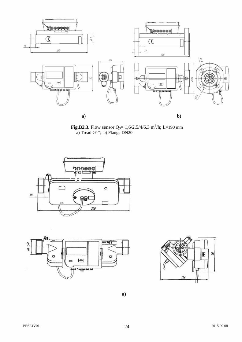
a) b)
Fig.B2.3. Flow sensor Q3= 1,6/2,5/4/6,3 m3/h; L=190 mm a) Tread G1“; b) Flange DN20
a)
PESF4V01 2015 09 08 25
ANNEX B (continuous)
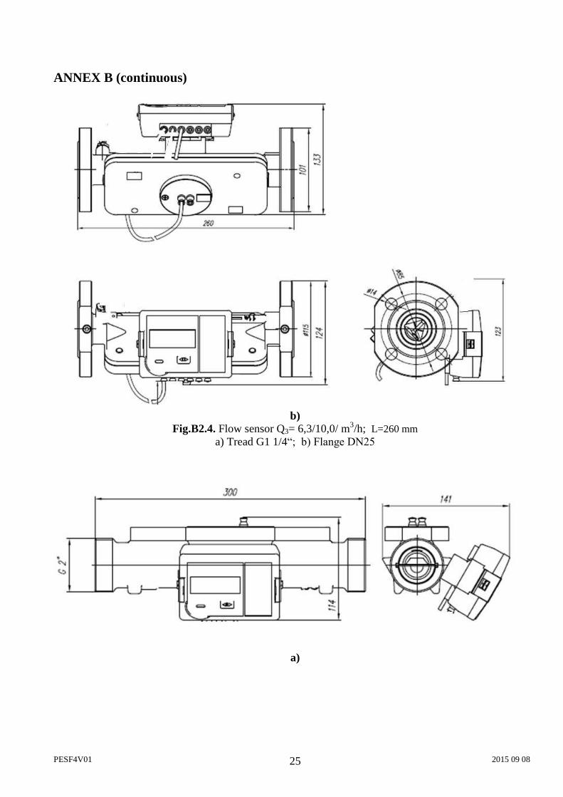
b)
Fig.B2.4. Flow sensor Q3= 6,3/10,0/ m3/h; L=260 mm a) Tread G1 1/4“; b) Flange DN25
a)
PESF4V01 2015 09 08 26
ANNEX B (continuous)
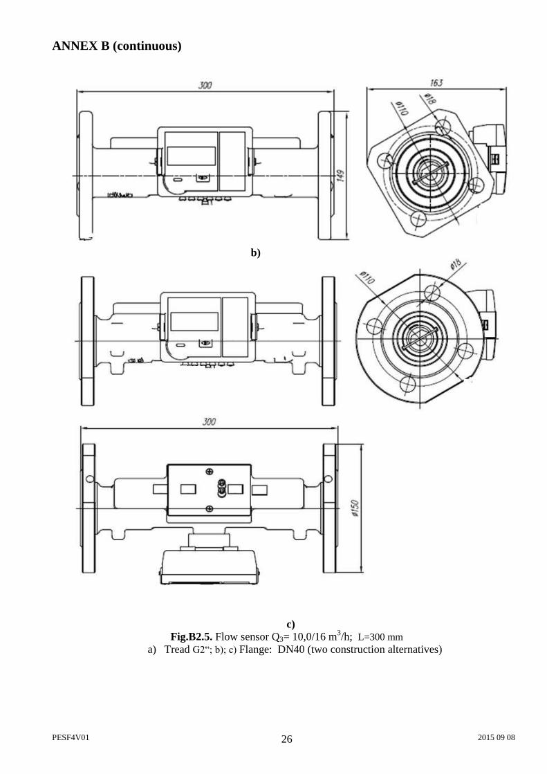
b)
c) Fig.B2.5. Flow sensor Q3= 10,0/16 m3/h; L=300 mm
a) Tread G2“; b); c) Flange: DN40 (two construction alternatives)
PESF4V01 2015 09 08 27
ANNEX B (continuous)
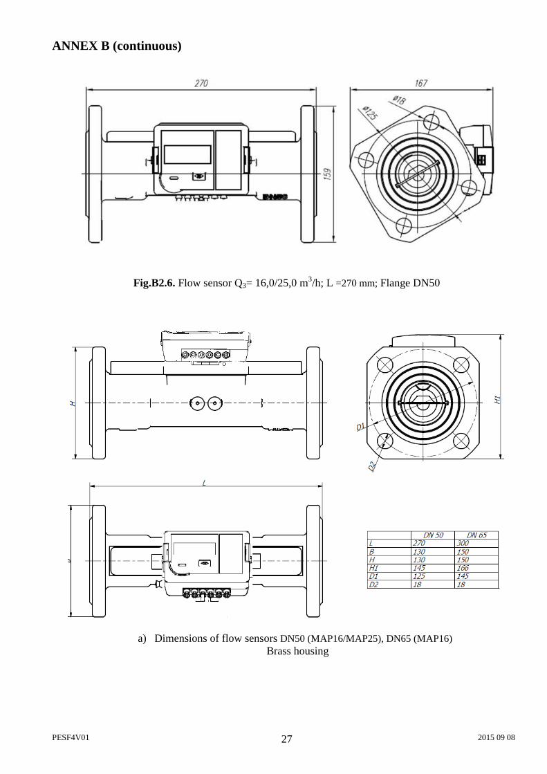
Fig.B2.6. Flow sensor Q3= 16,0/25,0 m3/h; L =270 mm; Flange DN50
a) Dimensions of flow sensors DN50 (MAP16/MAP25), DN65 (MAP16)
Brass housing
PESF4V01 2015 09 08 28
ANNEX B (continuous)
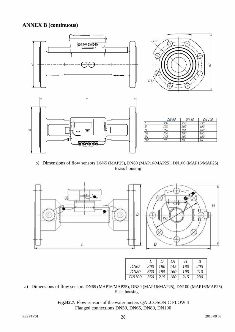
b) Dimensions of flow sensors DN65 (MAP25), DN80 (MAP16/MAP25), DN100 (MAP16/MAP25) Brass housing
a) Dimensions of flow sensors DN65 (MAP16/MAP25), DN80 (MAP16/MAP25), DN100 (MAP16/MAP25)
Steel housing
Fig.B2.7. Flow sensors of the water meters QALCOSONIC FLOW 4 Flanged connections DN50, DN65, DN80, DN100
L D D1 H B DN65 300 180 145 180 205 DN80 350 195 160 195 210
DN100
350 215 180 215 230
PESF4V01 2015 09 08 29
ANNEX C
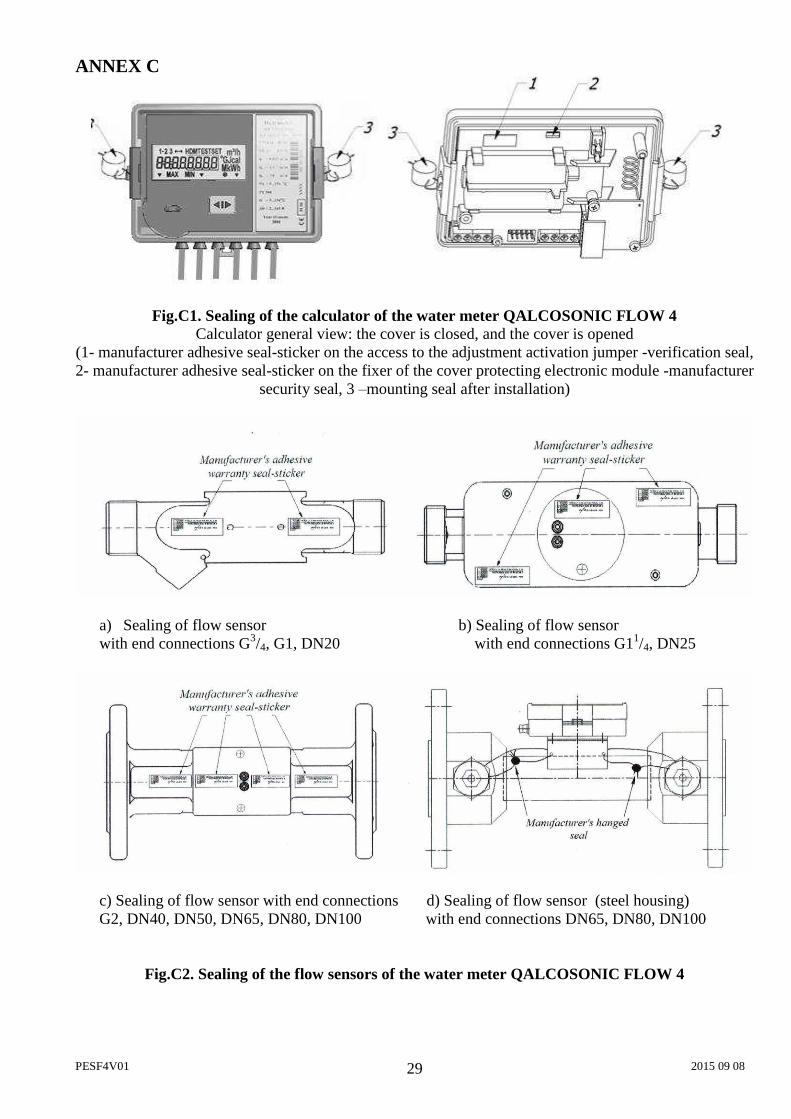
Fig.C1. Sealing of the calculator of the water meter QALCOSONIC FLOW 4 Calculator general view: the cover is closed, and the cover is opened
(1- manufacturer adhesive seal-sticker on the access to the adjustment activation jumper -verification seal, 2- manufacturer adhesive seal-sticker on the fixer of the cover protecting electronic module -manufacturer
security seal, 3 –mounting seal after installation)
a) Sealing of flow sensor b) Sealing of flow sensor with end connections G3/4, G1, DN20 with end connections G11/4, DN25
c) Sealing of flow sensor with end connections d) Sealing of flow sensor (steel housing) G2, DN40, DN50, DN65, DN80, DN100 with end connections DN65, DN80, DN100
Fig.C2. Sealing of the flow sensors of the water meter QALCOSONIC FLOW 4