ultrasonic water flow measurement (rev. a)
TRANSCRIPT

MC
U SN74LVC2T45
DUM
TS
5A63
157
TS
5A63
157
THS4521
RTX
RRX
GPIO
GND
GPIO
3.3 V
TR1
TR2
GPIO
LCD
ADC
Transceiver or SoC
PrepaymentNFC or RFID
Power
TI DesignsUltrasonic Water Flow Measurement
Design Overview Design FeaturesThis Ultrasonic Water Flow Measurement system is • Ultra-Low Power − Approximate 20-Year Lifetimeideal for providing highly accurate measurement With Batteryacross wide-flow ranges as low as 1.4 GPM. The • Analog-to-Digital Converter (ADC)-Based Approachdesign is based on a single MCU with discrete analog Meets ISO 4064-1 EEC Applicable Normscomponents. The design uses a unique propriety
• Robust to Signal Amplitude Variations – Insensitivealgorithm that improves robustness and performanceto Received Signal Amplitudein flow measurement across a wide range of operating
• Allows Low-Power Implementation With Optimizedconditions. This design is fully compatible with TI RFSignal Processingplug-in evaluation modules for wireless advanced
metering infrastructure (AMI) networks. • Supports Sub-1GHz and 2.4-GHz RF WirelessCommunication ModulesDesign Resources
• Support for Low-Power Segment Liquid-CrystalDisplay (LCD) ControllerTool Folder
TIDM-ULTRASONIC-WATER-FLOW- ContainingMEASUREMENT Design Files Featured ApplicationsMSP430FR6972 Product Folder • Water MeterSN74LVC2T45 Product FolderTHS4521 Product FolderTS5A63157 Product Folder
ASK Our E2E ExpertsWEBENCH® Calculator Tools
1TIDUA10A–June 2015–Revised July 2015 Ultrasonic Water Flow MeasurementSubmit Documentation Feedback
Copyright © 2015, Texas Instruments Incorporated

System Description www.ti.com
An IMPORTANT NOTICE at the end of this TI reference design addresses authorized use, intellectual property matters and otherimportant disclaimers and information.
1 System DescriptionThe reference EVM design for the Ultrasonic Flow Meter comprises a 12-bit ADC and LCD controller on aTI MSP430FR6972™ MCU, discrete analog front-end (AFE) components, and a transducer.
The EVM consists of the MSP430FR6792 MCU with integrated LCD support, an RF module socket,discrete AFE circuitry, headers to connect the transducer, a AAA battery holder, and a 14-pin Joint TestAction Group (JTAG) header.
This system is a low-power design using the latest TI MCU MSP430FR6972 with FRAM to store theprogramming code. The system block diagram shows all the elements that the EVM has and the potentialadd-on modules, like the RF sub-system, near-field communication (NFC) module, or the radio-frequencyidentification (RFID) module that can be connected to the EVM.
The discrete AFE circuitry comprises a dual-bit, dual-supply bus transceiver; a single-pole, double-throw(SPDT) analog switch; and a very-low power, fully differential operational amplifier (op-amp). The slowmeter solution is based on a differential time of flight estimation with involving two transducers forupstream and downstream paths. The signal waveforms are transmitted between two adjacenttransducers (Transducer A and Transducer B). Transducer A transmits an upstream path signal thatTransducer B receives. The flight time for the signal can be calculated using the known velocity of soundand length between the transducers. Transducer B transmits a downstream path signal to Transducer Aand calculates the time of flight. The upstream and downstream waveforms are then processed on themain MCU to obtain the volume. The benefits of this solution are: naturally obtaining the envelope ofsignal through ADC-based processing, provision of bubble detection features, and a robust response tosignal amplitude variations.
2 Ultrasonic Water Flow Measurement TIDUA10A–June 2015–Revised July 2015Submit Documentation Feedback
Copyright © 2015, Texas Instruments Incorporated
MC
U SN74LVC2T45
DUM
TS
5A63
157
TS
5A63
157
THS4521
RTX
RRX
GPIO
GND
GPIO
3.3 V
TR1
TR2
GPIO
LCD
ADC
Transceiver or SoC
PrepaymentNFC or RFID
Power
www.ti.com Block Diagram
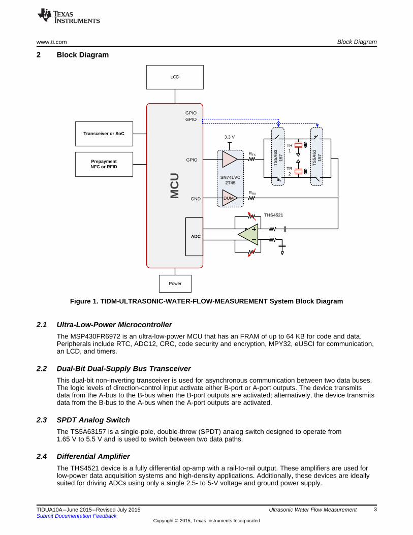
2 Block Diagram
Figure 1. TIDM-ULTRASONIC-WATER-FLOW-MEASUREMENT System Block Diagram
2.1 Ultra-Low-Power MicrocontrollerThe MSP430FR6972 is an ultra-low-power MCU that has an FRAM of up to 64 KB for code and data.Peripherals include RTC, ADC12, CRC, code security and encryption, MPY32, eUSCI for communication,an LCD, and timers.
2.2 Dual-Bit Dual-Supply Bus TransceiverThis dual-bit non-inverting transceiver is used for asynchronous communication between two data buses.The logic levels of direction-control input activate either B-port or A-port outputs. The device transmitsdata from the A-bus to the B-bus when the B-port outputs are activated; alternatively, the device transmitsdata from the B-bus to the A-bus when the A-port outputs are activated.
2.3 SPDT Analog SwitchThe TS5A63157 is a single-pole, double-throw (SPDT) analog switch designed to operate from1.65 V to 5.5 V and is used to switch between two data paths.
2.4 Differential AmplifierThe THS4521 device is a fully differential op-amp with a rail-to-rail output. These amplifiers are used forlow-power data acquisition systems and high-density applications. Additionally, these devices are ideallysuited for driving ADCs using only a single 2.5- to 5-V voltage and ground power supply.
3TIDUA10A–June 2015–Revised July 2015 Ultrasonic Water Flow MeasurementSubmit Documentation Feedback
Copyright © 2015, Texas Instruments Incorporated

1.2
1.3
3
1.1
2
1.4
4
5
6
7
System Design Theory www.ti.com
3 System Design Theory
Figure 2. EVM Board
The main board comprises an MSP430FR6972 MCU with an LCD display. The board powers eitherthrough an external DC-DC supply, JTAG, battery, or USB to provide 3.3 V. The board can divide intomultiple parts for the use of developing flow meters with RF capabilities. Refer to Table 1 for a descriptionof the board layout.
Table 1. Description of Main Board Layout
PART DESCRIPTIONPower supply options to power main board
1.1 Jumper setting to power board through AAA batteries1.2 USB connection to PC to power board1.3 Jumper setting to power board through JTAG1.4 External 3.3-V DC-DC supply
A socket for RF modules of sub-1 GHz or 2.4 GHz or RFID, connecting to the MCU with SPI,2 universal asynchronous receiver and transmitter (UART), and I/O3 Push-button switch to implement key control4 Reset button − this board does not have an on or off switch; to restart, push the reset button5 JTAG interface to connect to board6 Headers to connect external transducers7 Analog front-end layout section
4 Ultrasonic Water Flow Measurement TIDUA10A–June 2015–Revised July 2015Submit Documentation Feedback
Copyright © 2015, Texas Instruments Incorporated

Symmetric trace length
www.ti.com System Design Theory
The core component of the layout is the AFE and the user must carefully route this section of the board.TI recommends ensuring that the trace lengths of signals in the analog section of the board aresymmetrical and short. Figure 3 highlights a section of the layout with an example of symmetrical tracelengths.
Figure 3. Design Layout – Analog
5TIDUA10A–June 2015–Revised July 2015 Ultrasonic Water Flow MeasurementSubmit Documentation Feedback
Copyright © 2015, Texas Instruments Incorporated

Test Setup www.ti.com
4 Test SetupThe following procedure details the testing of the board (note that the test firmware is pre-programmed onthe main board). For more details on downloading the firmware onto the MSP430 device, refer to Section2 of following TI Wiki: Generating and Loading MSP430 Binary Files.1. Analyze the impedance of each Audiowell transducer by connecting the test fixture to a precision
impedance analyzer. The resonant frequency of Audiowell transducers used in the test setup is 1 MHz.2. Place jumpers on the main board on:
• JP1 – provides power to AFE circuitry• JP3 – external crystal• JP4, JP5, JP6, JP7, JP8, and JP9 – JTAG debugger
3. Connect the Audiowell transducers to jumpers J1 and J2 as Figure 4 shows. This test setup uses abrass pipe developed by Audiowell.
Figure 4. Transducers Connected to Main Board
For more information on Audiowell, visit the product page: http://www.audiowell.com/en/product-detail.aspx?id=80.
4. Power the board by connecting an external 3.3-V DC supply to the DVCC header and DGND header,as Figure 5 shows. The LED3 (power) on the board turns ON to indicate that the board was poweredsuccessfully.
6 Ultrasonic Water Flow Measurement TIDUA10A–June 2015–Revised July 2015Submit Documentation Feedback
Copyright © 2015, Texas Instruments Incorporated
C10 pad
GND
3.3-V DC
LED3
www.ti.com Test Setup
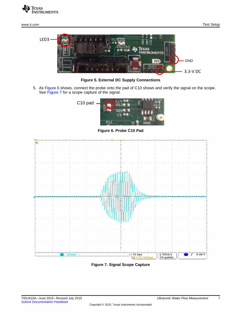
Figure 5. External DC Supply Connections
5. As Figure 6 shows, connect the probe onto the pad of C10 shows and verify the signal on the scope.See Figure 7 for a scope capture of the signal.
Figure 6. Probe C10 Pad
Figure 7. Signal Scope Capture
7TIDUA10A–June 2015–Revised July 2015 Ultrasonic Water Flow MeasurementSubmit Documentation Feedback
Copyright © 2015, Texas Instruments Incorporated
Water reservoir
PumpDesired flow
rate
Test flow meter
PVC
Couplings
Reference flow meter
Test Setup www.ti.com
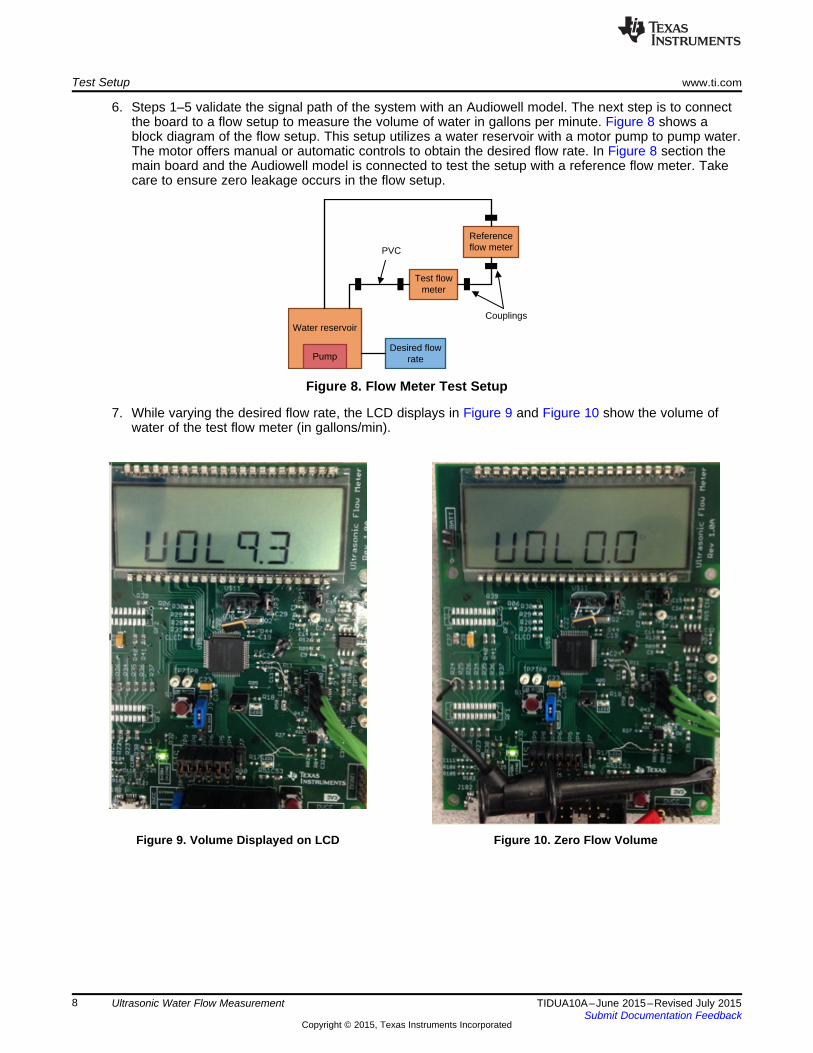
6. Steps 1–5 validate the signal path of the system with an Audiowell model. The next step is to connectthe board to a flow setup to measure the volume of water in gallons per minute. Figure 8 shows ablock diagram of the flow setup. This setup utilizes a water reservoir with a motor pump to pump water.The motor offers manual or automatic controls to obtain the desired flow rate. In Figure 8 section themain board and the Audiowell model is connected to test the setup with a reference flow meter. Takecare to ensure zero leakage occurs in the flow setup.
Figure 8. Flow Meter Test Setup
7. While varying the desired flow rate, the LCD displays in Figure 9 and Figure 10 show the volume ofwater of the test flow meter (in gallons/min).
Figure 9. Volume Displayed on LCD Figure 10. Zero Flow Volume
8 Ultrasonic Water Flow Measurement TIDUA10A–June 2015–Revised July 2015Submit Documentation Feedback
Copyright © 2015, Texas Instruments Incorporated

1 1.5 2 2.5 3 3.5 4 4.5 51
1.5
2
2.5
3
3.5
4
4.5
5
D001D001
MorningAfternoonEvening
www.ti.com Test Data
5 Test DataFigure 11 shows the volume of water computed by the main board with an Audiowell model connectedacross varying desired flow rates. The test results were captured by varying the flow of water multiplestimes throughout the day to validate the system across time and temperature. The accuracy error of thesystem was approximately 1% based on the captured test data.
The zero flow drift at room temperature across time is very low for this system and the standard deviationfor a single shot measurement is < 25 ps. The current consumption of the system is approximately 20 uA.
Figure 11. Test Results
9TIDUA10A–June 2015–Revised July 2015 Ultrasonic Water Flow MeasurementSubmit Documentation Feedback
Copyright © 2015, Texas Instruments Incorporated

SN74LVC2T45DCUR
TS5A63157 TS5A63157
THS4521ID
VIN+
VIN-
+V
S-V
S
PD
VOUT-
VOCM
VOUT+
0R
0R
0R
200
40.2K
40.2K
100
100
6.49K
6.49K
10K
0.1uF
2.2uF 2.2uF
2.2uF
0.1uF
2.2uF
0.1uF
0.1uF
0.1uF
0.1uF
0.1uF
560pF
560pF
DNP
0.22uF
0R
0R
DNP
DNP
DN
P
GND
+3V3
GND
GND
GND
GND
0R
GND GND
GNDGND
GND
GND GND
GND GND
2.2uF
GND GND
GNDGND
GND GND
GND
GND
GND
+3V3
GND GNDGND
200
DNP
GNDGND
0R
0R
0R
DNP
DNP
GND
GND
VCCB8
B17
B26
A12
GND4
A23
DIR5
VCCA1
U$3V+
5
COM4
IN6
NC3
NO1
GND2
U$1U$2
V+5
COM4
IN6
NC3
NO1
GND2
U$4
8
1 4
63
5
7
2
R02
R04
R03
R07
R08
R16
R09
R13
R10
R15
R14
C3
C1 C2
C5
C26
C21
C4
C6
C7
C8
C16
C9
C14
C10
C12
FB1
1 2
1
J1
2J2
TP1 TP2
R01
R31
C11
C13
R11
R27
C15
R50
TP3 TP4
R05
1 2
JP1
TP5 TP6
R19
R42
R43
C31
C32
TX1TX
DVCC
RX2TX2
TXBUF
US_DS_SEL_1
XDUCER1
XDUCER2
RX_OUT
US_DS_SEL_2
AIN14
P3.7_R5
3V3A3V3A
3V3A
3V3A
DVCC_AFE
DVCC_AFE
DVCC_AFE
RX RX1
AIN15
TRANSDUCER2CONNECTOR
TRANSDUCER1CONNECTOR
3V3A
3V3A
3V3A
3V3A
3V3A
Design Files www.ti.com
6 Design Files
6.1 SchematicsTo download the schematics for each board, see the design files at TIDM-ULTRASONIC-WATER-FLOW-MEASUREMENT.
Figure 12. Schematics Page 1
6.2 Bill of MaterialsTo download the bill of materials (BOM) for each board, see the design files atTIDM-ULTRASONIC-WATER-FLOW-MEASUREMENT.
6.3 Layout PrintsTo download the layout prints for each board, see the design files at TIDM-ULTRASONIC-WATER-FLOW-MEASUREMENT.
6.4 Eagle ProjectTo download the Eagle project files for each board, see the design files atTIDM-ULTRASONIC-WATER-FLOW-MEASUREMENT.
6.5 Gerber FilesTo download the Gerber project files for each board, see the design files atTIDM-ULTRASONIC-WATER-FLOW-MEASUREMENT.
10 Ultrasonic Water Flow Measurement TIDUA10A–June 2015–Revised July 2015Submit Documentation Feedback
Copyright © 2015, Texas Instruments Incorporated

www.ti.com Design Files
6.6 Assembly DrawingsTo download the assembly drawings for each board, see the design files atTIDM-ULTRASONIC-WATER-FLOW-MEASUREMENT.
6.7 Software FilesTo download the software files, see the design files at TIDM-ULTRASONIC-WATER-FLOW-MEASUREMENT.
7 References
1. Texas Instruments, TI E2E™ Community, Online Engineer Community, http://e2e.ti.com/
8 About the AuthorNAVEEN KALA is a system applications engineer at Texas Instruments, where he is responsible forproviding technical support and training on Smart Grid solutions and driving solutions for SmartGrid/Metering, and working on defining future requirements in roadmap. He received the M.Eng. degree inelectrical and computer engineering from the University of Iowa.
11TIDUA10A–June 2015–Revised July 2015 Ultrasonic Water Flow MeasurementSubmit Documentation Feedback
Copyright © 2015, Texas Instruments Incorporated

Revision A www.ti.com
Revision A
Changes from Original (June 2015) to A Revision ......................................................................................................... Page
• Changed title from Ultrasonic Water Meter Design Using Time-to-Digital Conversion to Ultrasonic Water FlowMeasurement............................................................................................................................... 1
NOTE: Page numbers for previous revisions may differ from page numbers in the current version.
12 Revision History TIDUA10A–June 2015–Revised July 2015Submit Documentation Feedback
Copyright © 2015, Texas Instruments Incorporated

IMPORTANT NOTICE FOR TI REFERENCE DESIGNS
Texas Instruments Incorporated ("TI") reference designs are solely intended to assist designers (“Buyers”) who are developing systems thatincorporate TI semiconductor products (also referred to herein as “components”). Buyer understands and agrees that Buyer remainsresponsible for using its independent analysis, evaluation and judgment in designing Buyer’s systems and products.TI reference designs have been created using standard laboratory conditions and engineering practices. TI has not conducted anytesting other than that specifically described in the published documentation for a particular reference design. TI may makecorrections, enhancements, improvements and other changes to its reference designs.Buyers are authorized to use TI reference designs with the TI component(s) identified in each particular reference design and to modify thereference design in the development of their end products. HOWEVER, NO OTHER LICENSE, EXPRESS OR IMPLIED, BY ESTOPPELOR OTHERWISE TO ANY OTHER TI INTELLECTUAL PROPERTY RIGHT, AND NO LICENSE TO ANY THIRD PARTY TECHNOLOGYOR INTELLECTUAL PROPERTY RIGHT, IS GRANTED HEREIN, including but not limited to any patent right, copyright, mask work right,or other intellectual property right relating to any combination, machine, or process in which TI components or services are used.Information published by TI regarding third-party products or services does not constitute a license to use such products or services, or awarranty or endorsement thereof. Use of such information may require a license from a third party under the patents or other intellectualproperty of the third party, or a license from TI under the patents or other intellectual property of TI.TI REFERENCE DESIGNS ARE PROVIDED "AS IS". TI MAKES NO WARRANTIES OR REPRESENTATIONS WITH REGARD TO THEREFERENCE DESIGNS OR USE OF THE REFERENCE DESIGNS, EXPRESS, IMPLIED OR STATUTORY, INCLUDING ACCURACY ORCOMPLETENESS. TI DISCLAIMS ANY WARRANTY OF TITLE AND ANY IMPLIED WARRANTIES OF MERCHANTABILITY, FITNESSFOR A PARTICULAR PURPOSE, QUIET ENJOYMENT, QUIET POSSESSION, AND NON-INFRINGEMENT OF ANY THIRD PARTYINTELLECTUAL PROPERTY RIGHTS WITH REGARD TO TI REFERENCE DESIGNS OR USE THEREOF. TI SHALL NOT BE LIABLEFOR AND SHALL NOT DEFEND OR INDEMNIFY BUYERS AGAINST ANY THIRD PARTY INFRINGEMENT CLAIM THAT RELATES TOOR IS BASED ON A COMBINATION OF COMPONENTS PROVIDED IN A TI REFERENCE DESIGN. IN NO EVENT SHALL TI BELIABLE FOR ANY ACTUAL, SPECIAL, INCIDENTAL, CONSEQUENTIAL OR INDIRECT DAMAGES, HOWEVER CAUSED, ON ANYTHEORY OF LIABILITY AND WHETHER OR NOT TI HAS BEEN ADVISED OF THE POSSIBILITY OF SUCH DAMAGES, ARISING INANY WAY OUT OF TI REFERENCE DESIGNS OR BUYER’S USE OF TI REFERENCE DESIGNS.TI reserves the right to make corrections, enhancements, improvements and other changes to its semiconductor products and services perJESD46, latest issue, and to discontinue any product or service per JESD48, latest issue. Buyers should obtain the latest relevantinformation before placing orders and should verify that such information is current and complete. All semiconductor products are soldsubject to TI’s terms and conditions of sale supplied at the time of order acknowledgment.TI warrants performance of its components to the specifications applicable at the time of sale, in accordance with the warranty in TI’s termsand conditions of sale of semiconductor products. Testing and other quality control techniques for TI components are used to the extent TIdeems necessary to support this warranty. Except where mandated by applicable law, testing of all parameters of each component is notnecessarily performed.TI assumes no liability for applications assistance or the design of Buyers’ products. Buyers are responsible for their products andapplications using TI components. To minimize the risks associated with Buyers’ products and applications, Buyers should provideadequate design and operating safeguards.Reproduction of significant portions of TI information in TI data books, data sheets or reference designs is permissible only if reproduction iswithout alteration and is accompanied by all associated warranties, conditions, limitations, and notices. TI is not responsible or liable forsuch altered documentation. Information of third parties may be subject to additional restrictions.Buyer acknowledges and agrees that it is solely responsible for compliance with all legal, regulatory and safety-related requirementsconcerning its products, and any use of TI components in its applications, notwithstanding any applications-related information or supportthat may be provided by TI. Buyer represents and agrees that it has all the necessary expertise to create and implement safeguards thatanticipate dangerous failures, monitor failures and their consequences, lessen the likelihood of dangerous failures and take appropriateremedial actions. Buyer will fully indemnify TI and its representatives against any damages arising out of the use of any TI components inBuyer’s safety-critical applications.In some cases, TI components may be promoted specifically to facilitate safety-related applications. With such components, TI’s goal is tohelp enable customers to design and create their own end-product solutions that meet applicable functional safety standards andrequirements. Nonetheless, such components are subject to these terms.No TI components are authorized for use in FDA Class III (or similar life-critical medical equipment) unless authorized officers of the partieshave executed an agreement specifically governing such use.Only those TI components that TI has specifically designated as military grade or “enhanced plastic” are designed and intended for use inmilitary/aerospace applications or environments. Buyer acknowledges and agrees that any military or aerospace use of TI components thathave not been so designated is solely at Buyer's risk, and Buyer is solely responsible for compliance with all legal and regulatoryrequirements in connection with such use.TI has specifically designated certain components as meeting ISO/TS16949 requirements, mainly for automotive use. In any case of use ofnon-designated products, TI will not be responsible for any failure to meet ISO/TS16949.IMPORTANT NOTICE
Mailing Address: Texas Instruments, Post Office Box 655303, Dallas, Texas 75265Copyright © 2015, Texas Instruments Incorporated