ge measurement & control panaflow z3 ultrasonic flow meter ... · measurement & control...
TRANSCRIPT
GE Measurement & Control
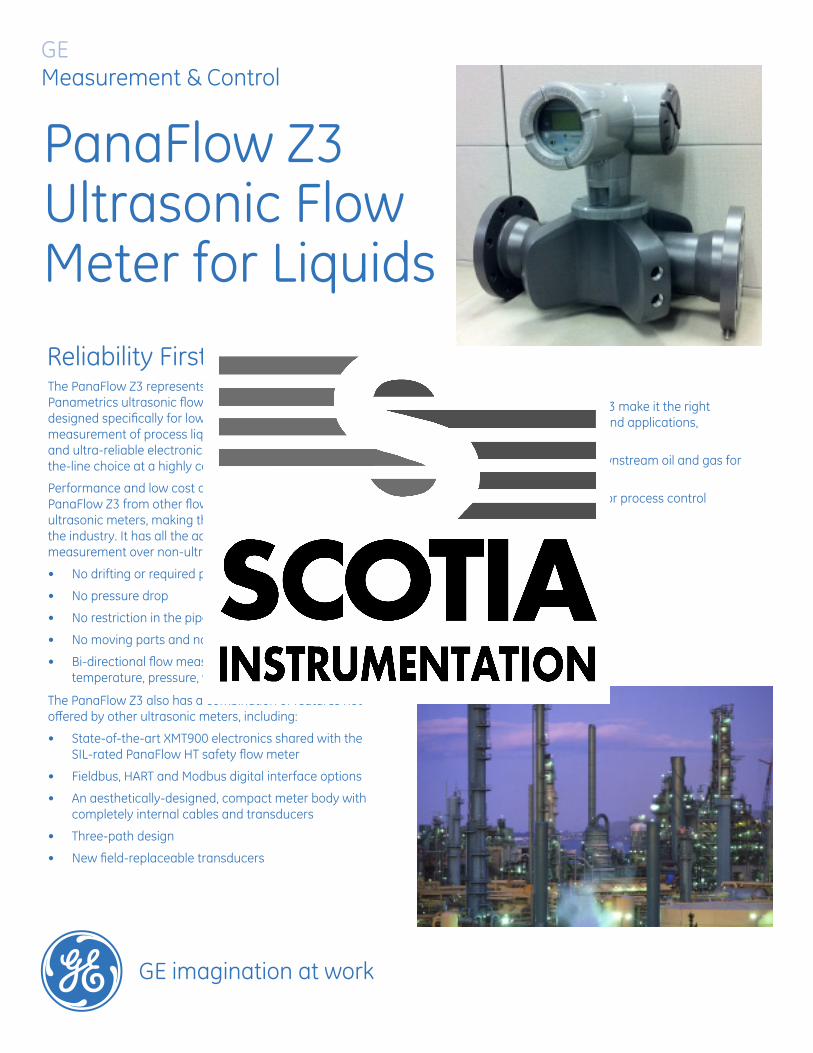
PanaFlow Z3 Ultrasonic Flow Meter for LiquidsReliability First
GE imagination at work
The PanaFlow Z3 represents the latest generation of Panametrics ultrasonic flow meters. It is a three-path meter designed specifically for low-risk, accurate and repeatable measurement of process liquids. With a sleek industrial design and ultra-reliable electronics, it provides operators a top-of-the-line choice at a highly competitive price.
Performance and low cost of ownership separate the PanaFlow Z3 from other flow technologies and from other ultrasonic meters, making the meter a reliability first in the industry. It has all the advantages of ultrasonic flow measurement over non-ultrasonic meters, including:
• No drifting or required periodic calibration
• No pressure drop
• No restriction in the pipe
• No moving parts and no filters or strainers
• Bi-directional flow measurement independent of temperature, pressure, viscosity and conductivity
The PanaFlow Z3 also has a combination of features not offered by other ultrasonic meters, including:
• State-of-the-art XMT900 electronics shared with the SIL-rated PanaFlow HT safety flow meter
• Fieldbus, HART and Modbus digital interface options
• An aesthetically-designed, compact meter body with completely internal cables and transducers
• Three-path design
• New field-replaceable transducers
Where PanaFlow Z3 ExcelsThe capabilities of the PanaFlow Z3 make it the right meter for a number of industries and applications, including:
• Upstream, midstream and downstream oil and gas for allocation measurement
• Chemical and petrochemical for process control
• Water and wastewater
• Power
• HVAC
• Batching and blending
• Plant utilities
• Irrigation
• Cooling water
Overall Operation & PerformanceLiquid TypesLiquids: accoustically conductive fluids, including most liquids, and many liquids with small amounts of entrained solids or gas bubbles
Flow Measurement± 0.5% of reading, patented Correlation Transit TimeTM model
Accuracy• ±0.5% of reading, for velocity above 1.7 ft/sec (0.5 m/s)• ±1 mm/s of reading, for velocity below 1.7 ft/sec (0.5 m/s)Final installation assumes a fully developed flow profile (typically 10 diameters upstream and 5 diameters downstream of straight pipe run) and single-phase fluids. Applications with piping arrangements that induce swirl (e.g. two out-of-plane elbows) may require additional straight run or flow conditioning.
CalibrationAll meters are water calibrated and delivered with a traceable calibration certificate.
Repeatability±0.2% of reading
Range (Bi-directional)0.1 to 40 ft/s (0.03 to 12.19 m/s)
Process Temperature-4°F to 284°F (-20°C to 140°C)
Electronics Environmental ProtectionIP67
Hazardous Area ClassificationsFM/CSA (pending), ATEX and IEC; Zone1 Ex d; Class1, Div1 Gr. BCD
Input/Output• Two 4-20 mA isolated outputs• Two additional programmable outputs (either frequency, pulse, alarm or control outputs)
Power Supply• 100 to 240 VAC• 12 to 28 VDC
Digital Interfaces• HART® over 4-20 mA output• Foundation Fieldbus• Modbus
Electronics MountingLocal and remote mounting
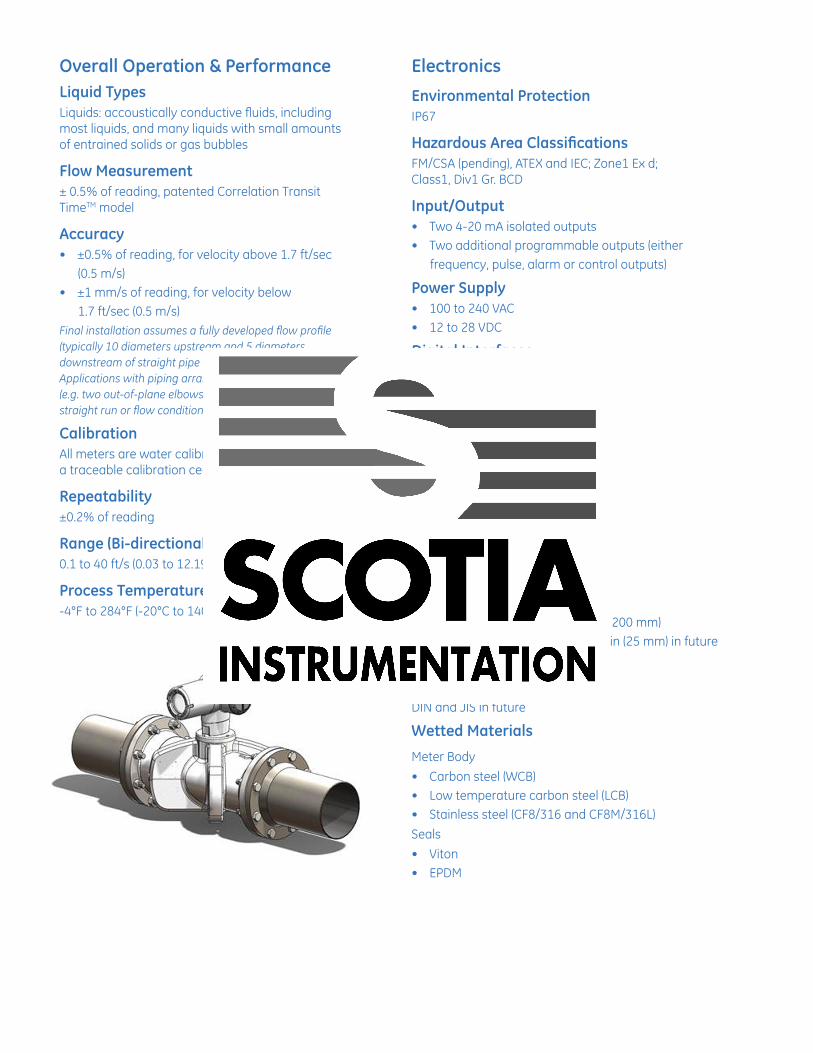
Meter BodyTransducersIn-process field accessible
Path ConfigurationThree-path configuration
Pipe Sizes• 3, 4, 6 and 8 in (80, 100, 150 and 200 mm)• Up to 24 in (600 mm), down to 1 in (25 mm) in future
Flange Ratings150#, 300# and 600#
DIN and JIS in future
Wetted Materials
Meter Body• Carbon steel (WCB)• Low temperature carbon steel (LCB)• Stainless steel (CF8/316 and CF8M/316L)Seals• Viton• EPDM
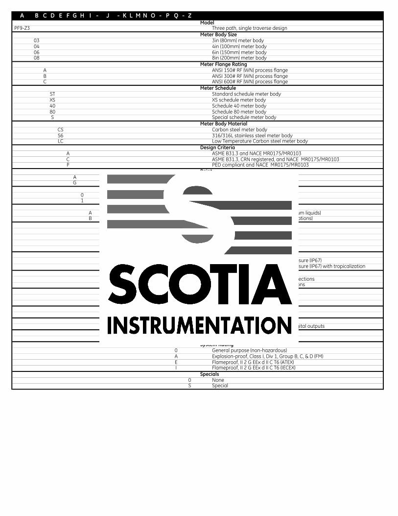
A B C D E F G H I - J - K L M N O - P Q - ZX Model
PF9-Z3 Three path, single traverse designX Meter Body Size
03 3in (80mm) meter body04 4in (100mm) meter body06 6in (150mm) meter body08 8in (200mm) meter body
X Meter Flange RatingA ANSI 150# RF (WN) process flangeB ANSI 300# RF (WN) process flangeC ANSI 600# RF (WN) process flange
X Meter ScheduleST Standard schedule meter bodyXS XS schedule meter body40 Schedule 40 meter body80 Schedule 80 meter bodyS Special schedule meter body
X Meter Body MaterialCS Carbon steel meter bodyS6 316/316L stainless steel meter bodyLC Low Temperature Carbon steel meter body
X Design CriteriaA ASME B31.3 and NACE MR0175/MR0103C ASME B31.3, CRN registered, and NACE MR0175/MR0103P PED compliant and NACE MR0175/MR0103
X PaintA No paint (Stainless Steel Version)G Standard paint
X NDE0 No NDE documentation1 NDE documentation
Transducer Mounting MaterialA Viton (Recommended for most petroleum liquids)B EDPM (Recommended for water applications)
X Electronics MountingL Local mounting of XMT900 electronics
R25 Remote: 25 feet of cableR50 Remote: 50 feet of cableR100 Remote: 100 feet of cable
X XMT900 Enclosure1 Epoxy coated XMT900 aluminum enclosure (IP67)2 Epoxy coated XMT900 aluminum enclosure (IP67) with tropicalization
X Connections1 3/4" NPT power and input/output connections2 M20 power and input/output connections
X Power1 100-240 VAC input power2 12-28 VDC input power
X Display Option1 Local display
X CommunicationD One analog/HART , one analog, two digital outputs
X Transducers/Buffers5 Normal temperature Z3 transducers
X System Rating0 General purpose (non-hazardous) A Explosion-proof, Class I, Div 1, Group B, C, & D (FM)E Flameproof, II 2 G EEx d II C T6 (ATEX)I Flameproof, II 2 G EEx d II C T6 (IECEX)
X Specials0 NoneS Special

© 2012 General Electric Company. All Rights Reserved. Specifications are subject to change without notice. GE is a registered trademark of General Electric Company. Other company or product names mentioned in this document may be trademarks or registered trademarks of their respective companies, which are not affiliated with GE.
BR-204A
For more information, contact:Thomas MichalowskiGlobal Product ManagerUltrasonic Liquid FlowGE Measurement & ControlT: +1 978-437-1823M +1 [email protected]
www.ge-mcs.com