ultimateloadtestsonbearingbehavioroflarge-diameter
TRANSCRIPT

Research ArticleUltimate Load Tests on Bearing Behavior of Large-DiameterBored Piles in Weathered Rock Foundation
Xiaoyu Bai 12 Xueying Liu1 Mingyi Zhang12 Yonghong Wang12 and Nan Yan 12
1Department of Civil Engineering Qingdao University of Technological Qingdao Shandong 266033 China2Cooperative Innovation Center of Engineering Construction and Safety in Shandong Blue Economic Zone QingdaoShandong 266033 China
Correspondence should be addressed to Nan Yan yannan0527163com
Received 19 May 2020 Revised 25 August 2020 Accepted 29 August 2020 Published 8 September 2020
Academic Editor Liborio Cavaleri
Copyright copy 2020 Xiaoyu Bai et al +is is an open access article distributed under the Creative Commons Attribution Licensewhich permits unrestricted use distribution and reproduction in any medium provided the original work is properly cited
Based on the vertical compressive static load test and pile mechanics test of three large diameter bored piles (one of the testpiles was treated with postgrouting) in granite gneisses foundation the bearing capacity deformation characteristics andinfluencing factors of the single pile under the limit state are analyzed and compared with the recommended values of surveyreport and the recommended values of current codes By comparing the measured and theoretical values of pile axial forcethe bearing capacity of cast-in-place pile under normal and limit conditions is analyzed +e experimental results show thatthe Q-s curve of large-diameter rock-socketed mud wall retaining bored pile with a length-diameter ratio of 25ndash33 and rock-socketed depth of 5ndash8 d shows a rapid growth After grouting treatment the ultimate compressive bearing capacity of singlepile is improved the maximum settlement is reduced by 66 the rebound rate is reduced by 111 and the settlement effectof controlling pile top is not significant +e bearing capacity and deformation characteristics of the three test piles are lessaffected by length-diameter ratio and rock-socketed depth For postgrouting piles the ratio of frictional resistance of rock-socketed segment and the ratio of pile lateral resistance are less affected by length-diameter ratio and rock-socketed depthwhile for postgrouting piles the ratio of pile lateral resistance is more affected by rock-socketed depth +e pile endresistance ratio of the three test piles is significantly affected by the rock-socketed depth whether or not the pile sidepostgrouting treatment is carried out
1 Introduction
In recent years large diameter mud wall protection boredpile (Dge 800mm) has been widely used in pile foundationengineering such as expressway railway long-span bridgeand high-rise building by virtue of its advantages of highbearing capacity small deformation convenient construc-tion etc shown in engineering practice [1ndash3] However dueto the high cost of damage test of rock-socketed cast-in-placepile and the difficulty of complete destructive test themeasured data of systematic and complete static load test arenot much which also restricts the comprehensive study ofbearing capacity of rock-socketed cast-in-place pile withlarge diameter [4ndash6] At present many scholars have carriedout a series of related researches on bearing characteristicsand load transfer mechanism of cast-in-place pile and
obtained beneficial results Li et al [7] carried out two full-scale load tests on super-long bored cast-in-place pilesobserved their field performance and proposed a simplifiedmethod for nonlinear analysis of load-displacement of singlepile Based on the theoretical and experimental researchmethods the bearing characteristics of pile and soil underpile top load are investigated Omer et al [8] carried out loadtests on large diameter piles onMercia mudstone foundationand analyzed and evaluated the current design methods ofpiles under such conditions Sudheesh et al [9] explored theload transfer mechanism and influencing factors of post-grouting pile in silty clay by means of test and numericalsimulation Xing et al [10] conducted on-site installation ofoptical fiber sensors on the rock-socketed pile of Hezhangbridge with a large diameter +rough the collection pro-cessing and analysis of test data during the construction of
HindawiAdvances in Civil EngineeringVolume 2020 Article ID 8821428 13 pageshttpsdoiorg10115520208821428
super-large rock-socketed piles the bearing characteristicsand load transfer mechanism of super-large rock-socketedpiles are discussed Balakrishnan et al [11] proposed a re-liable method for predicting the load deformation and loaddistribution curve of bored pile based on the weatheringprofile and engineering characteristics of the bored pile in aresidual regolith (Kenney hill formation) in Kuala Lumpuras well as the load deformation behavior of fully instru-mental test site performance data and load transfer designcharacteristics Zhou et al [12] studied the mechanicalperformance of pregrouting cast-in-place pile under theaction of pressure and tension through field test and three-dimensional finite element simulation Xu et al [13] ex-plored the construction process of large diameter (80m)deep hole piles based on the existence of groundwater inbedrock fractures and the location of huge concrete Zhanet al [14] confirmed the method based on allowable bearingcapacity and lateral resistance of rock socket drill shaft withtwo test pile structures and tests Strain gauge and tensionrod extensometer are installed in both test piles and thestatic compression load test results of the two test piles aregiven Seol et al [15] studied the load transfer method underthe axial load of rock-socketed drill shaft +e analysismethod of shear load transfer function and load transfercharacteristics of rock-socketed wellbore is emphasized Baiet al [16] conducted vertical compressive static load test andpile mechanics test for single pile with large diameter mudretaining wall in weathered rock foundation conductedlateral postgrouting test for 3 test piles and compared theirbearing characteristics deformation characteristics andinfluencing factors with those of nongrouting pile Chenet al [17] conducted a full-scale static load test on threebored piles based on the Qingdao area and compared themeasured lateral resistance along the rock wall with theprediction results using empirical methods in the literatureIt can be seen that the existing relevant research is mainlyfocused on the super-long drilling or punching in special soilor soft soil foundation and there are still deficiencies in theresearch on the ultimate bearing characteristics and failurecharacteristics of large diameter bored cast-in-place pilestreated by postgrouting
To this end this paper combined Rizhao proposedbuilding foundation treatment project the three large di-ameter bored cast-in-situ concrete piles slurry-supported(including 1 test pile by pile grouting construction tech-nology) for the single pile vertical compressive static loadtest and pile body mechanics compared and analyzed theirultimate bearing character failure behavior and influencingfactors and compared them with the current specificationsand survey report recommended value finishing large di-ameter side limit of bored cast-in-situ pile side frictionresistance pile size effect coefficient and enhancing thepostgrouting pile side friction coefficient in order to providea reference basis for similar projects
2 Project Summary
+e test site is a project in the south of Rizhao city +edestruction test of 3 mud retaining wall bored cast-in-place
piles TP1simTP3 was carried out in which TP2 was treatedwith postgrouting on the side of the pile and the groutingpipe was located at 160m of the pile +e pile ends ofTP1simTP3 are all embedded with fully weathered andstrongly weathered granite gneiss +e standard penetrationhammer number of each rock is 131 and 293 respectivelythe bearing capacity characteristic value is 250 kPa and260 kPa respectively and the compression modulus is65MPa and 200MPa respectively+e concrete strength ofthe pile is C30 the slurry is prepared with 425 ordinaryPortland cement the water-cement ratio is 055sim 070 thecement consumption of the grouting behind the single pileside of TP2 is 15 t and the flow is controlled at 40sim 50 Lmin +e grouting pressure of weathered rock is 50MPaand that of other soil layers is 20MPa +e quality standardof grouting is controlled by a dual-control method in whichthe grouting quantity is mainly controlled and the pumpingpressure is supplemented +e quality inspection and ac-ceptance of post-pile grouting shall be carried out in ac-cordance with technical code for construction pilefoundation (JGJ 94-2008) [18] +e relevant parameters ofthe test pile are shown in Table 1 +e structure of overlyingsoil layer on the rock foundation is relatively simple mainlyconsisting of quaternary mixed fill soil silty clay and sandysoil +e average stable groundwater level is about 15m+ephysical and mechanical properties of each soil layer areshown in Table 2
3 Test Scheme
31 TestMethods +e vertical compressive static load test ofa single pile used an anchor pile reaction beam loadingdevice and its reaction force system should have a safetyfactor not less than 12 times During the test the loadingand unloading method was carried out with the loadmaintained at a slow speed and four displacement sensorswere installed symmetrically on the pile top to test the piletop settlement and residual settlement under various loads+ree test piles are loaded in 10 levels and the first load is 2levels When unloading the unloading value of each level istwice the loading value of each level +e integrity test oflow-strain pile body and the vertical compressive static loadtest of single pile are in strict compliance with the relevantprovisions in the technical specification for testing ofbuilding foundation piles (JGJ 106-2014) [19] +e experi-mental process is shown in Figure 1
32 Sensor Layout Vibrating chord reinforcement stressmeter is widely used in the field of engineering stress andstrain measurement to fully understand the stress state ofthe component under test It has the advantages of highsensitivity and precision good linearity and stability andstrong anti-interference ability and it is waterproof anddurable During the internal force test of the single pile staticload test the sensor adopts a vibrating chord reinforcementstress meter its model is JTM-V1000 the range is 0sim 20 kNand its compressive stress and tensile stress measurementranges are 100MPa and 200MPa respectively +rough the
2 Advances in Civil Engineering
form of butt welding and coaxial connection with the mainrib of the steel cage heat insulation measures are takenduring welding to prevent damage to the sensor +e testleads are led out of the ground along the whole of the pilebody and they are protected with a soft bandage after beingled out+ere is no joint in the middle Avoid using the cableof the steel gauge to lift the steel stress gauge during use +esensors of the test piles TP1simTP3 are all located at 2m 5m8m 11m 14m 17m and 19m at the pile body Four steelbar stress gauges are installed on each section and the angleof the stress gauge is 90deg +e sensor distribution is shown inFigure 2
4 Calculation Method
41 Calculation Method of Pile Stress Measured ValueSteel bar meter calibration before embedding in theprocess of static loading step by step used the DP-YT-DSY-406A frequency of reading meter at the top of the piledisplacement test time record of reinforcing steel bar meterreadings namely initial readings before test and after thetest load in the process of reading the assumption in theprocess of test of reinforcement and concrete strain
coordination according to the calculation of reinforcingsteel bar meter frequency change characteristics of pileaxial force distribution are obtained According to thefrequency value measured each time calculate the stressvalue of the measuring point according to the followingequation [20]
σsi k F20 minus F
2i1113872 1113873 (1)
where σsi is the i-th strain of the reinforcement meter (kPa)k is the constant coefficient of the reinforcement meter F0is the zero frequency of the reinforcement meter (Hz) andFi is the measured frequency of the reinforcement meter(Hz)
+e strain of reinforcement is expressed as
εi σsiEs
(2)
where εi is the i-th strain variable of the reinforcement meterand Es is the elastic modulus of reinforcement (MPa)
+e concrete stress of pile body can be expressed as
σci Ec middot εi (3)
where σci is the normal stress of i section concrete (kPa) εi isthe concrete strain of i section and Ec is the elastic modulusof concrete (MPa)
Assuming the strain coordination between steel bar andconcrete in the test process the axial force Fi in the i-th testat a section of the pile can be expressed as
Fi Asiσsi + Aciσci (4)
where Asi is the area of steel reinforcement on i section (cm2)and Aci is the concrete area on the i section (cm2)
Table 1 Parameters of test piles
Test pilenumber
Pile diameter(m)
Pile length(m)
Depth of rock-socketed at pile end(m)
Estimated ultimate bearing capacity of single pile(kN)
TP1 100 2555 549 15000TP2 0800 2550 552 9700TP3 0800 2650 642 9700
Table 2 Parameters of soils
Soil layer number and name ρ (gcm3) W () Gs e ρd (gcm3) IL φ (deg) cq (kPa) α01minus02 (MPaminus1) Es01minus02 (MPa)
②minus1 Medium-coarse sand 186 173 265 0667 159 mdash 255 530 009 205⑤ Medium-coarse sand 197 186 265 0596 166 mdash 245 570 011 153⑥ Silty clay 187 243 271 0807 150 0470 172 270 031 580⑥minus2 Medium-coarse sand 200 193 265 0587 167 mdash 239 600 009 199⑦ Residual mucous soil 188 270 273 0832 149 0400 156 300 030 651Note c and φ were determined using the quick shear test
Figure 1 Static load test
Steel string typereinforcement stress meterPile top
3m 3m 3m 3m 3m 3m 3m 3m 2m
Pile end
Figure 2 Schematic diagram of sensor distribution
Advances in Civil Engineering 3
+e average lateral friction resistance between the twosections can be obtained by the axial force difference be-tween the two adjacent sections that is
qi Fi minus Fiminus1( 1113857
hiUp
(5)
where qi is the average lateral friction resistance of the i-thlayer of soil (kPa) Fi and Fiminus1 are the axial forces of the pileon and below the i-th layer of soil respectively (kN) hi is thethickness of the i-th layer of soil (cm) and Up is the sectioncircumference of the pile (cm)
After testing the survival rate of the rebar meter in thisexperiment is 92 During the test the axial force Pz of eachpile under each grade of load was obtained according toequations (1)sim(4) based on the frequency variation of theembedded reinforcement meter in the six test piles and theaverage lateral friction resistance qs was obtained fromequation (5) +e total lateral resistance Qs and pile endresistance Qp were obtained from the following equationsrespectively
Qs UP 1113944i
qihi (6)
Qp Q minus Qs (7)
where Qs is the total pile side resistance (kPa) Qp is pile endresistance and Q is pile top load (kPa)
42 4eoretical Calculation Method of Pile Axial ForceAccording to the load transfer theory [21] the equation forcalculating the pile axial force under the two kinds of dis-placement of pile top can be established as follows
(1) Under the action of load plastic failure occurs at thetop of the pile side with a depth of l0 in the failurezone (Δs(z)ge s0) +e lower part is in the elasticstate its depth range is l0~ l1 and it is in the elasticregion ((Δs(z)le s0) +e axial force P(z) in the pilebody is
P(z) Pl0
sinh η l0 minus z( 11138571113858 1113859
sinh η l1 minus l0( 11138571113858 1113859 (8)
(2) When the pile top is subjected to load and thesurrounding rocks are in an elastic state (s(z)le s0)the axial force P(z) in the pile body is
P(z) Pd
sinh η l1 minus z( 11138571113858 1113859
sinh ηl1( 1113857 (9)
+e above equations show that the axial force distri-bution of rock-socketed piles can be obtained as long as thecomprehensive influence coefficient η is determined by thematerial properties and geometric conditions of rock-socketed piles the surrounding rock properties and con-struction conditions etc are determined and the Q-s curveis obtained through field rock-socketed pile tests to obtain
the force required for unit displacement of rock-socketedpiles in the linear deformation section
5 Test Results and Analysis
51 Compressive Static Load Test Results of Single PileQ-s curves of the three test piles are shown in Figure 3 +emaximum load maximum settlement end resistance ratioand resilience of test pile are listed in Table 3
As can be seen from Figure 3Q-s curve of large-diameterrock-socketed mud wall protection bored cast-in-place pilewith length-diameter ratio (LD) of 25sim 33 and rock-socketed depth of 5Dsim 8D is of rapid growth type+ree testpiles were determined as class I piles after integrity testing oflow-strain pile bodies According to the determinationmethod of vertical ultimate bearing capacity of single pile inthe code [18] when TP1 TP2 and TP3 are respectivelyloaded to 10500 kN 9000 kN and 9700 kN the anchor pileappears obviously uplifted and the maximum settlementexceeds 40mm and the vertical ultimate bearing capacity ofsingle pile can be judged to be 9378 kN 8597 kN and9000 kN respectively At the initial stage of loading thesettlement of TP1 increased greatly and is rapidly comparedwith other test piles +is is mainly because the soil layer inthe non-rock-socketed section of test pile TP1 has less lateralconstraint and the relative displacement of pile and soil islarger and the Q-s curve at the initial stage is nearly linearWhen the load exceeds 6000 kN the Q-s curve grows slowlyAt this point the lateral friction resistance of soil layer pilesgradually develops the relative displacement of pile soil
TP1TP2TP3
50
40
30
20
10
0
s (m
m)
0 2 4 6 8 10 12Q (MN)
Figure 3 Q-s curves of test pile
4 Advances in Civil Engineering
decreases and the settlement of pile top mainly depends onthe settlement of pile end
In the same geotechnical layer the Q-s curves of TP2(treated by post-pile grouting) are consistent with those ofTP1 and TP3 (the length-diameter ratio and rock-socketeddepth are both small) +e reason is that at 16m of pile TP2under the influence of the grouting construction qualitybehind the pile (the grouting pressure and water cement ofthe pile are relatively high) the ultimate friction resistance ofthe pile side in rock-socketed section is weakened and theload is mainly borne by the lateral friction resistance pro-vided by the overlying soil layer of weathered rock and theload sharing ratio between pile end and pile side is about 1 4TP1 with a diameter of 10m shows the characteristics offriction end bearing pile +e ultimate friction resistance onthe pile side of the rock and soil layer below the fourth layerof silty clay is limited by the construction quality of the cast-in-place pile+e load sharing ratio between the pile end andthe pile side is about 11 to 1 2 When TP1 was loaded atgrade 1 and TP3 was loaded at grade 2 the load and set-tlement showed a near-linear change indicating that the piletop load was mainly borne by the pile end and the bearingcapacity of the pile side and the pile end was quite differentAfter applying the 1st grade load TP2 shows a broken linechange with the increase of the load and the slope graduallyincreases When the load reaches 9000 kN the settlement ofthe pile top exceeds the allowable value of the specification(40mm)
As can be seen from Table 3 the length-diameter ratiorock-socketed depth construction technology and pilequality of large-diameter bored piles have great influence onthe deformation characteristics of piles Under the samerock-soil layer condition when the LD is 25ndash33 and therock-socketed depth is within the range of 5 dndash8 d com-pared with TP1 and TP3 without the postgrouting treat-ment the ultimate compressive bearing capacity of singlepile does not increase the maximum settlement is reducedby 66 and the rebound rate is also significantly reducedabout 111 +e ability to control the settlement of pile topis not significantly improved Under the test conditionscompared with TP1 when the LD and rock-socketed depthof TP3 without lateral grouting were increased by 297 and169 respectively the bearing capacity was reduced by40 the maximum settlement increased by 35 and therebound rate was increased by 80 In conclusion thesettlement amount of TP1mainly comes from the settlementof pile end Compared with TP3 the strength of mud skin onthe pile side is greater +e lateral friction resistance of thepile in the soil layer above the rock-socketed section plays an
earlier role so the bearing capacity decreases and theresilience of the pile body decreases +e settlement of TP3pile top is mainly due to the compression of pile end+e pileend bears the load of pile top early and the resistance of pileend is large +e relative displacement of pile soil at the pileend increases and the lateral friction resistance of pile issmall To sum up it shows that the bearing capacity of thepiles without lateral backgrouting is greatly affected by thelength-diameter ratio while the deformation characteristicsare greatly affected by the rock-socketed depth
52 Variation Rule of Pile Axial Force As can be seen fromFigure 4 the axial forces of three large-diameter rock-socketed cast-in-place piles are consistent with the distri-bution law of the pile bodies and gradually decline from topto bottom +e attenuation curves are of the inner concaveand outer convex types +e variation rule is related to thelength-diameter ratio of piles the soil layer propertiesaround piles and pile ends the depth of rock-socketed theway of piling the quality and the construction technologyetc +rough the adjacent soil pile axial force statistics foundthat the average relative attenuation of similar length todiameter ratio and rock-socketed depth and pile quality isstable the pile grouting treatment is compared with pilewithout grouting treatment of piles pile axial force of av-erage relative attenuation rate increase is larger and thecoarse sand (loose) layer can be increased by 667 +elayer of medium coarse sand (slightly dense to mediumdense) can increase 333 +e silty clay layer (plasticizedIL 047) decreased by 162 a relatively small decrease+emedium coarse sand (medium dense) layer decreased by588 which was relatively small +e residual viscous soillayer (hard plastic IL 04) was reduced by 208 a rela-tively large decrease Postgrouting has a strongerstrengthening effect on the soil layer above the socketedrock When the pile quality is poor (the axial force of TP1and TP3 piles in Figure 3 decreases slowly along the depth itcan be inferred that there is a thick mud skin on the pile sideand the strength is low) the relative attenuation rate of theaxial force of pile is reduced by 205sim 34 in the shallowsoil layer about 6Dsim 8D from the pile top In the dense soillayer in the middle and lower part from the pile top for10Dsim 20D the decrease was 185sim 60 with an averagedecrease of 393 In fully weathered strata the decrease was511 and in strongly weathered strata 707
Taking TP3 as an example the theoretical calculatedvalue and the measured value of its axial force are comparedand analyzed [22 23] According to Q-s curve the
Table 3 Deformation and capacity of test piles
Test pilenumber LD
Rock-socketeddepth (m)
Maximumload (kN)
Standard valueof ultimate
bearing capacity(kN)
Pile endresistance(times102 kN)
Endresistanceration
Maximumsettlement(mm)
Residualsedimentation
rate ()
Resilientrate ()
TP1 2555 549 10500 9378 69 2 4498 726 274TP2 3188 552 9000 8597 29 12 4368 805 195TP3 3313 642 9700 9000 36 23 4656 704 296
Advances in Civil Engineering 5
displacement of pile top corresponding to 8000 kN and9000 kN is 12mm and 24mm respectively +roughanalysis and calculation the pile rock displacement limitvalue s0 17mm η 011 +erefore the load of 8000 kNand 9000 kN corresponds to the load under elastic state andplastic failure respectively According to the above calcu-lation equation the axial force under elastic and plasticfailure can be obtained along the rock-socketed depthtransfer curve as shown in Figures 5 and 6 respectively
In Figure 5 the pile top load is 80MN and the pile topdisplacement is 37mm which is less than the elastic limitdisplacement value and is in the elastic shear state +etheoretical curve is a smooth hyperbola which is consistentwith the measured line In Figure 6 the pile top load is90MN and the theoretical value under the pile top dis-placement is 42mm compared with the measured valueSince the pile top displacement is larger than the elastic limitdisplacement value it is calculated in sections the depth ofthe failure zone is 408m and the failure load is 52MNwhich is basically at the same depth as the linear foldingpoint (4m) of the measured load transfer curve
53 Variation Rule of Average Lateral Friction Resistance onPile Side As can be seen from Figure 7 the vertical variationof pile lateral friction at the junction of soft and hard soillayers is manifested by sudden change of pile lateral friction+e lateral change rule is that with the increase of pile topload the lateral friction of pile first increases linearly thengradually shows a nonlinear increase and then graduallydecreases and tends to be stable after reaching the limit oflateral friction For the bored piles with mud wall protection(the rock-socketed depth is 5Dsim 8D) the lateral frictionresistance of the grouting and nongrouting piles in the fullyweathered and highly weathered rocks is played in the uppersmall lower large mode
By comparing test piles TP1simTP3 it can be found thatthe pile lateral friction resistance can be increased by 3125
in the plain filled soil layer compared with the test pileswithout the lateral grouting treatment Medium coarse sand(loose) layer can be increased by 07 and medium coarsesand (slightly dense to medium dense) layer can be increasedby 191 Silty clay layers (malleable IL 047) increased by190Medium coarse sand (medium dense) layer decreasedby 17 residual viscous soil (hard plastic IL 04) in-creased by 100 the lateral friction resistance of rock-socketed pile plays a small role which indicates that post-grouting plays a relatively large role in strengthening thelateral friction resistance of the pile above the fully weath-ered and strongly weathered gneiss beds When the length-diameter ratio is consistent with the rock-socketed depth ofthe test pile without lateral grouting treatment the pile withgood construction quality (class I pile without thicker mud
Plain fillMedium-
coarse sand
Silty clay
Eluvialclay
Fully weatheredgranite gneiss
Strongly weatheredgranite gneiss
Medium-coarse sand
Medium-coarse sand zc
zc
zc
10500kN9000kN7500kN
6000kN4500kN3000kN
0 20 40 60 80 100 120Pz ( 102 kN)
2421181512
9630
L (m
)
(a)
9000kN8000kN7000kN6000kN
5000kN4000kN3000kN2000kN
0 20 40 60 80 100Pz (102 kN)
2421181512
9630
L (m
)
(b)
9000kN8000kN7000kN6000kN
5000kN4000kN3000kN2000kN
0 20 40 60 80 100Pz (102 kN)
2421181512
9630
L (m
)
(c)
Figure 4 +e distribution curve of axial force along pile (a) TP1 (b) TP2 (c) TP3
Measured valueCalculated value
30 35 40 45 50 55 60Pz (102 kN)
24
21
18
15
Rock
-soc
kete
d de
pth
(m)
Figure 5 Distribution of pile axial force when wall rock is elastic
6 Advances in Civil Engineering
skin) can increase the lateral friction resistance of the pile inthe plain filled soil layer by 176 +e medium coarse sand(loose) layer can be increased by 241+e layer of mediumcoarse sand (slightly densesimmedium dense) can be in-creased by 14 +e silty clay layer (malleable IL 047)increased by 47 Medium coarse sand (medium dense)layer can be increased by 170 Residual viscous soil (hardplastic IL 04) increased by 190 +e fully weatheredrock section can first increase by 510 and then decrease by48+e highly weathered rock segment can be increased by141 When the length-diameter ratio is consistent with therock-socketed depth the good grouting effect (the groutingpressure and water-cement ratio reach the grouting standardand are not too large) can increase the lateral friction
resistance of piles in the plain soil layer by 591 +emedium coarse sand (loose) layer can be increased by 488+e layer of medium coarse sand (slightly densesimmediumdense) can be increased by 429 +e silty clay layer(plasticized IL 047) increased by 425 at first and thendecreased by 298 a relatively small decrease Mediumcoarse sand (medium dense) layer can be increased by 261+e residual viscous soil layer (hard plastic IL 04) in-creased by 209 and then decreased by 276 with arelatively small decrease +e fully weathered rock layer canbe increased by 714 and decreased by 286 Stronglyweathered rock formations can be raised by 714 to 786It can be seen that the strengthening effect of postgroutingon pile lateral friction is weak in rock-socketed section +is
Measured valueCalculated value
30 35 40 45 50 55 60 65 70Pz (102 kN)
24
21
18
15
Rock
-soc
kete
d de
pth
(m)
Figure 6 Distribution of pile axial force when partial wall rock is plastic
10500kN9000kN7500kN
6000kN4500kN3000kN
Plain fillMedium-
coarse sand
Silty clay
Eluvialclay
Fully weatheredgranite gneiss
Strongly weatheredgranite gneiss
Medium-coarse sand
Medium-coarse sand zc
zc
zc
0 20 40 60 80 100qs (kPa)
24
21
18
15
12
9
6
3
0
L (m
)
(a)
9000kN8000kN7000kN6000kN
5000kN4000kN3000kN2000kN
0 30 60 90 120 150 180 210qs (kPa)
24
21
18
15
12
9
6
3
0
L (m
)
(b)
9000kN8000kN7000kN6000kN
5000kN4000kN3000kN2000kN
0 40 80 120 160 200qs (kPa)
24
21
18
15
12
9
6
3
0
L (m
)
(c)
Figure 7 +e distribution of pile side friction along pile (a) TP1 (b) TP2 (c) TP3
Advances in Civil Engineering 7
is because the grouting pressure and water-cement ratio ofrock-socketed section are too large under test conditionsresulting in segregation of cement slurry to a certain extentthus weakening the shear strength of the interface andlimiting the lateral friction resistance of the pile in rock-socketed section +erefore under the condition that thelength-diameter ratio and rock-socketed depth are the samecompared with TP2 the lateral friction resistance of pile inrock-socketed segment plays a greater role
54 Deformation Characteristics of Rock-Socketed PileAccording to the settlement data obtained in the failure testthe variation rules of the settlement with the lateral frictionresistance and pile end resistance were drawn as shown inFigure 8
As can be seen from Figure 8 TP1 shows the behavior ofpile bearing at the frictional end With the increase of set-tlement at the pile top the pile end resistance increaseslinearly and the load on the pile top is mainly borne by thepile end+e ultimate frictional resistance of pile side is firstlydeveloped in the middle and upper soil layers of pile bodyand the ultimate frictional resistance of pile side of residualviscous soil medium coarse sand layer and rock-socketedsection is relatively small within the range of 12Dsim 20D frompile top +erefore when the settlement of pile top exceeds25mm the total pile lateral friction gradually increases butthe increase range is small and the settlement of pile topmainly comes from the settlement of pile end TP2 shows thebehavior of end-bearing friction pile Compared with the testpile without lateral grouting treatment the lateral frictionresistance of pile is more fully developed TP2 and TP3 havethe same change rules and the curve changes slowly +evertical distance between pile lateral friction resistance andpile end resistance change curves is small and uniform andthe load sharing capacity of pile lateral friction resistance islimited Pile end resistance plays an early role with a lowbearing capacity and a large settlement
+e load-bearing ratio between the pile side and theequivalent pile end of each test pile and the ratio between theultimate frictional resistance of the pile side in rock-socketedsection to the total ultimate lateral frictional resistance thelength-diameter ratio and the rock-socketed depth areshown in Figures 9 and 10
As can be seen from Figures 9 and 10 under this testcondition the increase of (qgsqs) of the test pile withoutpostgrouting treatment on the side of the pile reaches 2180with the increase of length-diameter ratio indicating that therock-socketed section of the test pile TP3 has a certainstrength of soil skin on the side of the pile and its rock-socketed section has a greater normal constraint so the pilequality is better and it is greatly affected by the length-diameter ratio and rock-socketed depth It can be foundfrom the comparison of various test piles that comparedwith TP2 treated with lateral postgrouting and TP1 treatedwith nonlateral postgrouting the pile end resistance sharingratio (QpQ) has little change which indicates that thegrouting treatment does not significantly improve the pilequality Compared with TP1 the length-diameter ratio
increased by 297 and the rock-socketed depth increasedby 169 but the (QpQ) decreased by 370 Comparedwith TP1 the length-diameter ratio and rock-socketed depthof test pile TP3 without lateral grouting increased by 297and 169 respectively but the (QpQ) decreased by 370It shows that (QpQ) is always significantly affected by rock-socketed depth whether or not it is treated by post-pile
TP3TP2
Qs
Qp
Qs
Qp
Qs
Qp
TP1
0
15
30
45
60
75
90
Fric
tiona
l res
istan
ce (1
02 kN
)
30 400 20 5010Settlement of pile top (mm)
Figure 8 +e curves of friction resistance and pipe top settlement
34
QsQ
QpQ
qgsqs
0 20 40 60 80()
32
30
28
26
24
LD
Figure 9 +e curves of load sharing ratio and aspect ratio
8 Advances in Civil Engineering
QsQ
QpQ
qgsqs
0 20 40 60 80()
68
65
62
59
56
53
50
Rock
-soc
kete
d de
pth
(m)
Figure 10 +e curves of load sharing ratio and rocking depth
Measured valuesRecommended value of survey report
Slity
clay
Med
ium
-co
arse
sand
Med
ium
-co
arse
sand
Med
ium
-co
arse
sand
Resid
ual
clay
Hig
hly
wea
ther
edgr
anite
Fully
wea
ther
edgr
anite
0
40
80
120
160
200
Ulti
mat
e sid
e fric
tion
resis
tanc
e (kP
a)
(a)
Measured valuesRecommended value of survey report
Slity
clay
Med
ium
-co
arse
sand
Med
ium
-co
arse
sand
Med
ium
-co
arse
sand
Resid
ual
clay
Hig
hly
wea
ther
edgr
anite
Fully
wea
ther
edgr
anite
0
40
80
120
160
200
Ulti
mat
e sid
e fric
tion
resis
tanc
e (kP
a)
(b)
Figure 11 Continued
Advances in Civil Engineering 9
grouting Under this test condition for the test pile withoutgrouting treatment the pile side friction resistance sharingratio (QsQ) increased by 708 with the increase of length-diameter ratio and rock-socketed depth (QsQ) was greatlyaffected by rock-socketed depth (QsQ) was not affected bylength-diameter ratio and rock-socketed depth in the testpile after grouting
55 Comparative Analysis +e measured value of ultimatefriction resistance on the pile side was compared with therecommended value of the survey report and the en-hancement coefficient of lateral friction resistance on thepostgrouting pile and the size effect coefficient on thelarge-diameter pile side were compared with the rec-ommended value of technical specification for buildingpile foundation (JGJ94-2008) [18] as shown inFigures 11ndash13
Figure 11 shows that in the guarantee slurry-sup-ported drilled filling pile under the premise of the qualityof pile (duration of thickness of mud mud mud con-sistency) the combination of Figure 6 and the charac-teristics of the frictional end bearing pile can be judgedTP1 part shows thick mud by the pile side the test pileside friction resistance limits some of its soil comparedwith the standard value which is larger Medium coarsesand (loose) can be increased by 179 sim 464 mediumcoarse sand (slightly dense simmedium dense) by 718 sim911 silty clay (plasticized IL 047) by 469 sim 538medium coarse sand (medium dense) by 742 sim 120and residual viscous soil (hard plastic IL 04) by702 sim 218 TP3rsquos ultimate frictional resistance infully weathered rock formations increased by only 154
compared to the recommended values in the surveyreport +e reason is that in combination with Figure 6the ultimate friction resistance on the pile side of TP1 islimited and the strength of rock-socketed section islower than the general soil layer It can be seen fromFigure 7 that the pile end resistance plays a big role andthe pile side friction resistance in the strongly weatheredrock stratum has begun to play its role However thefully weathered rock stratum does not increase signifi-cantly when playing its role in the upper layer but haslimited potential and is greatly affected by the con-struction quality Regarding TP2 under the influence ofgrouting quality the pile side friction resistance in rock-socketed section is weakened due to the high groutingpressure As can be seen from Figure 12 for the cast-in-place pile (D 10 m) the size effect coefficient of pileside in sand can be increased by 179 sim 120 with alarge increase It can be increased by 701 sim 539 inviscous soil For the cast-in-place pile with a pile di-ameter of 08 m the size effect coefficient of pile side canbe increased by 698 sim 742 in sandy soil and 720 onaverage which is mainly and significantly increased by218 sim 360 in viscous soil +e measured value ismuch higher than the standard value As can be seenfrom Figure 12 by comparing the measured pile sidefriction resistance value with the standard value of initiallimit pile side friction resistance determined by thespecification [18] it is found that the enhanced coeffi-cient of pile side friction resistance after grouting can beincreased by 843 in the medium coarse sand layer and28 in the viscous soil and the measured value isslightly higher than the recommended value of thespecification
Measured valuesRecommended value of survey report
Slity
clay
Med
ium
-co
arse
sand
Med
ium
-co
arse
sand
Med
ium
-co
arse
sand
Resid
ual
clay
Hig
hly
wea
ther
edgr
anite
Fully
wea
ther
edgr
anite
0
40
80
120
160
200
Ulti
mat
e sid
e fric
tion
resis
tanc
e (kP
a)
(c)
Figure 11 Pile shaft skin ultimate friction and code value in different soil layers (a) TP1 (b) TP2 (c) TP3
10 Advances in Civil Engineering
6 Conclusions
(1) Under the test conditions the axial force attenuationcurve of the pile body of the large diameter mudretaining wall bored cast-in-situ pile was of a steepdrop +e ultimate bearing capacity of the cast-in-place piles treated with postpile grouting is notsignificantly improved compared with the cast-in-place piles without postpile grouting
(2) +e ultimate bearing capacity of single pile wasincreased by 140 the maximum settlement wasdecreased by 62 the rebound rate was not im-proved significantly and the effect of controlling thesettlement of pile top was enhanced Under the testconditions the bearing capacity and deformationcharacteristics of the three test piles are greatly af-fected by length-diameter ratio and rock-socketeddepth
Side
dim
ensio
n ef
fect
coef
ficie
nt o
f lar
ge d
iam
eter
pile
Measured valuesSpecification values
Slity
clay
Med
ium
-co
arse
sand
Med
ium
-co
arse
sand
Med
ium
-co
arse
sand
Resid
ual
clay
00
04
08
12
16
20
(a)
Side
dim
ensio
n ef
fect
coef
ficie
nt o
f lar
ge d
iam
eter
pile
Measured valuesSpecification values
Slity
clay
Med
ium
-co
arse
sand
Med
ium
-co
arse
sand
Resid
ual
clay
Med
ium
-co
arse
sand
00
04
08
12
16
20
(b)
Figure 12 Size effect coefficient of pile side and code value in different soil layers (a) TP1 (b) TP3
Measured valuesSpecification values
Slity
clay
Med
ium
-co
arse
sand
Med
ium
-co
arse
sand
Resid
ual
clay
Med
ium
-co
arse
sand
Hig
hly
wea
ther
edgr
anite
Fully
wea
ther
edgr
anite
00
05
10
15
20
25
30
β s
Figure 13 Side friction resistance enhancement factor of the postgrouting pile and code value in different soil layers
Advances in Civil Engineering 11
(3) After the grouting treatment the lateral friction-resistance ratio of rock-socketed section (qgsqs)
was reduced under the influence of length-diam-eter ratio and rock-socketed depth +e pile endresistance ratio (QpQ) is significantly affected bythe rock-socketed depth After postgroutingtreatment the lateral friction-resistance ratio(QsQ) is almost negligible under the influence oflength-diameter ratio and rock-socketed depthwhile (QsQ) is more significantly under the in-fluence of rock-socketed depth for test pileswithout postgrouting treatment
(4) +e measured value of pile side ultimate frictionresistance in some soil layers is higher than therecommended value in the survey report +e in-crease was 718 in medium coarse sand (slightlydense to medium dense) 469 in silty clay (plas-ticized IL 047) and 742 in medium coarse sand(medium dense)
(5) For the cast-in-place pile with a pile diameter of 10mthe pile side size effect coefficient was larger in sandysoil and only increased by 701 in viscous soil Forthe cast-in-place pile with a pile diameter of 08m thepile side size effect coefficient is also larger in sandysoil which can be increased by 218 in viscous soil+e lateral friction coefficient can be increased by843 in the sand and 28 in the viscous soil
Data Availability
+e experimental data used to support the findings of thisstudy will be made available upon request
Conflicts of Interest
+e authors declare that there are no conflicts of interestregarding the publication of this paper
Acknowledgments
+e authors would like to acknowledge the support by theNational Natural Science Foundation of China (grant nos51708316 51778312 and 51809146) the China PostdoctoralScience Foundation Funding (grant no 2018M632641) theShandong Key Research and Development Program (grant nos2017GSF16107 and 2018GSF117008) the Shandong ProvincialPostdoctoral Innovation Program of China (grant no201903043) Project of Shandong Province Higher EducationalScience and Technology Program (grant no J16LG02) andQingdao Postdoctoral Applied Research Program (grant no2018101)
References
[1] M H Nguyen and B H Fellenius ldquoBidirectional cell tests onnon-grouted and grouted large-diameter bored pilesrdquo Journalof Geo-Engineering Sciences vol 2 no 3-4 pp 105ndash117 2015
[2] Q Zhang Z Zhang F Yu and J Liu ldquoField performance oflong bored piles within piled raftsrdquo Proceedings of the
Institution of Civil Engineers-Geotechnical Engineeringvol 163 no 6 pp 293ndash305 2010
[3] R Radhakrishnan and C F Leung ldquoLoad transfer behavior ofrock-socketed pilesrdquo Journal of Geotechnical Engineeringvol 115 no 6 pp 755ndash768 1989
[4] N-W Liu Z-M Zhang Q-Q Zhang and K Fang ldquoDe-structive field tests on mobilization of end resistance of cast-in-situ bored pilesrdquo Journal of Central South Universityvol 20 no 4 pp 1071ndash1078 2013
[5] C Haberfield and B Collingwood ldquoRock-socketed pile designand construction a better wayrdquo Proceedings of the Institutionof Civil Engineers Geotechnical Engineering vol 159 no 3pp 207ndash217 2006
[6] L Zhang ldquoPrediction of end-bearing capacity of rock-sock-eted shafts considering rock quality designation (RQD)rdquoCanadian Geotechnical Journal vol 47 no 10 pp 1071ndash10842010
[7] S-C Li Q Zhang Q-Q Zhang and L-P Li ldquoField andtheoretical study of the response of super-long bored pilesubjected to compressive loadrdquo Marine Georesources ampGeotechnology vol 34 no 1 pp 71ndash78 2016
[8] J R Omer J R Omer R B Robinson R Delpak andJ K C Shih ldquoLarge-scale pile tests in Mercia mudstone dataanalysis and evaluation of current design methodsrdquo Geo-technical and Geological Engineering vol 21 no 3 pp 167ndash200 2003
[9] S +iyyakkandi M Mcvay D Bloomquist and P LaildquoExperimental study numerical modeling of and axial pre-diction approach to base grouted drilled shafts in cohesionlesssoilsrdquo Acta Geotechnica vol 9 no 3 pp 439ndash454 2014
[10] H Xing J Han and C Li ldquoPerformance monitoring ofsuperlarge-diameter rock-socketed piles by optic fiber sen-sorsrdquo Materials Testing vol 59 no 6 pp 585ndash590 2017
[11] E G Balakrishnan A S Balasubramaniam and N Phien-Wej ldquoLoad deformation analysis of bored piles in residualweathered formationrdquo Journal of Geotechnical and Geo-environmental Engineering vol 125 no 2 pp 122ndash131 1999
[12] J-J Zhou X-N Gong K-H Wang R-H Zhang andJ-J Yan ldquoTesting and modeling the behavior of pre-boredgrouting planted piles under compression and tensionrdquo ActaGeotechnica vol 12 no 5 pp 1061ndash1075 2017
[13] W Xu B Liu Y-Q Zhou and Y-H Han ldquoConstruction of80m diameter rock-socketed piles in a large-scale deep ex-cavationrdquo Geotechnical and Geological Engineering vol 35no 5 pp 2455ndash2466 2017
[14] C Zhan and J-H Yin ldquoField static load tests on drilled shaftfounded on or socketed into rockrdquo Canadian GeotechnicalJournal vol 37 no 6 pp 1283ndash1294 2000
[15] H Seol S Jeong and S Cho ldquoAnalytical method for load-transfer characteristics of rock-socketed drilled shaftsrdquoJournal of Geotechnical and Geoenvironmental Engineeringvol 135 no 6 pp 778ndash789 2009
[16] X Y Bai Y Y Mou M Y Zhang et al ldquoExperimental studyon bearing capacity of grouting after weathering large-di-ameter cast-in-place pilesrdquo Journal of Civil and Environ-mental Engineering (Chinese and English) vol 41 no 2pp 1ndash11 2019
[17] X-Y Chen M-Y Zhang and X-Y Bai ldquoAxial resistance ofbored piles socketed into soft rockrdquo KSCE Journal of CivilEngineering vol 23 no 1 pp 46ndash55 2019
[18] China Academy of Building Research JGJ 94-2018 TechnicalCode for Building Pile foundations China Architecture ampBuilding Press Beijing China 2018
12 Advances in Civil Engineering
[19] China Academy of Building Research JGJ 106-2014 TechnicalCode for Testing of Building Foundation piles China Archi-tecture amp Building Press Beijing China 2014
[20] Z Wang and W Richwien ldquoDisplacement of a pile underaxial loadrdquo Geotechnique vol 49 no 4 pp 537ndash541 1999
[21] M Zhao Y Lei and X Liu ldquoAnalysis of load transfer of rock-socketed piles based on characteristics of pile-rock structuralplanerdquo Chinese Journal of Rock Mechanics amp Engineeringvol 28 no 1 pp 103ndash110 2009
[22] J Li Y Tan and F Liang ldquoAmodified analysis method for thenonlinear load transfer behaviour of axially loaded pilesrdquoKSCE Journal of Civil Engineering vol 16 no 3 pp 325ndash3332012
[23] F Liang X Liang C Wang J Wang and Y Li ldquoInfluence ofrigidity and load condition on the contact stress and settle-ment deformation of a spread foundationrdquo Journal of Testingand Evaluation vol 47 no 2 Article ID 20180290 2019
Advances in Civil Engineering 13
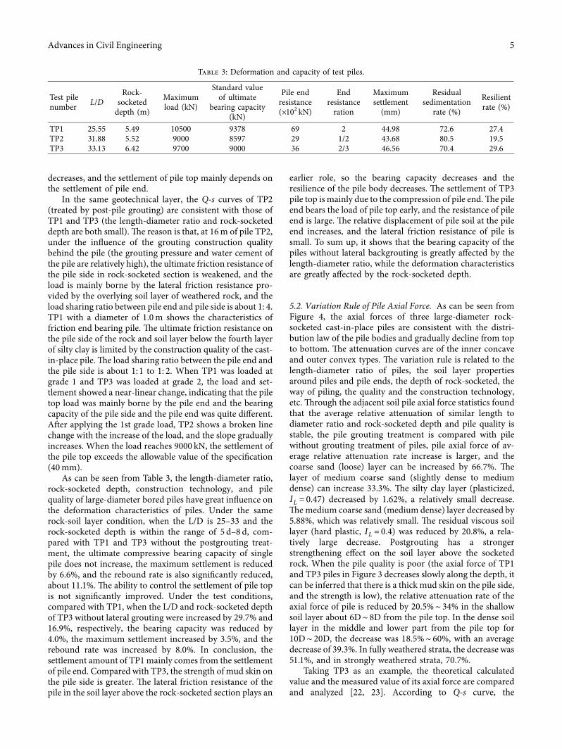
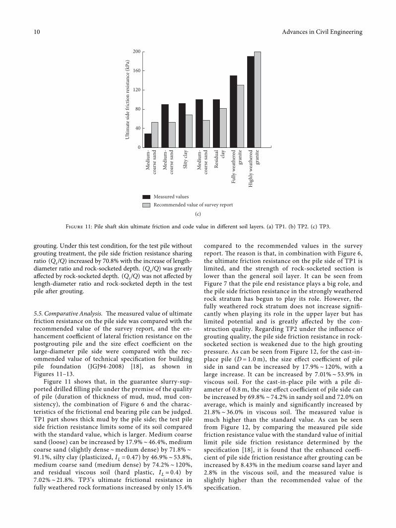