uhe castanhão
DESCRIPTION
Descrição de uma das principais barragens brasileirasTRANSCRIPT

THE MULTIPURPOSE CASTANHÃODEVELOPMENT ON THE JAGUARIBE RIVER
This paper was written by Ana Teresa Mattos Marques de Sousa Ponte, Keila Margareth Cândido Rolim, Maria Zita Timbó Araújo,Vanda Tereza Costa Malveira with the collaboration of Marcus Henrique Rodrigues Rangel and Getúlio Peixoto Maia.The figures were prepared by Alex Matos.

Main Brazilian Dams III
7 4
THE MULTIPURPOSE CASTANHÃODEVELOPMENT ON THE JAGUARIBE RIVER
1. INTRODUCTION
The Castanhão dam and reservoir are located on theJaguaribe river, in the area by the name of Boqueirão doCunha (see Photo 1), in the State of Ceará, in theNortheast Region of Brazil, at 5º27'S e 38º28'W(see Figure 1).
The National Department for Droughts - DNOCS wasresponsible for the project development, that started in1995 (the tender documents for the civil works were issuedin 1991) and was completed in 2003 by AndradeGutierrez Construction Company.
The main purposes of Castanhão Dam are: regulationof the Jaguaribe river, water supply to the riverineinhabitants and an increase in water supply for themetropolitan area of Fortaleza, control of floods on thelow Jaguaribe valley, diversion to the Chapada do Apodi(the Jaguaribe river and Chapada do Apodi 43,000 ha
Figure 1 - Location of Castanhão Project
Photo 1 - Aerial View of Boqueirão do Cunha
irrigation system), future hydroelectric development, fishfarms, tourist development and water storage for the SãoFrancisco River Integration Project.

Main Brazilian Dams III
7 5
2. THE DEVELOPMENT
The development of Castanhão includes the followingstructures: the main dam, spillway, intake, nine auxiliarydikes and a plug fuse spillway, as can be seen inFigure 2 and Photo 2. In the future a powerplant is plannedto be built using waters from the São Francisco RiverIntegration Project, at present underway.
The first topographical and geological studies in theBoqueirão do Cunha date from 1910 when the NationalDepartment For Drought Prevention agency, DNOCS(at that time named IOCS, the Inspectorate for DroughtPrevention Works). In the 1930's and 1950's workcontinued on the feasibility studies. In 1982 the NationalDepartment of Works and Sanitation, DNOS hired aconsortium, Noronha - Hidroterra to study the "IntegratedDevelopment of the Water Resources and Land of theSemi - Arid Northeast Region by Diversion of the HydraulicResources of the São Francisco River", in which theproject of Castanhão was included.
In 1987 DNOS hired the Consortium Hidroservice -Noronha to elaborate the preliminary and detailed designof the dam. With the extinction of DNOS in March 1990all work stopped and the contract was subrogated to theMinistry of Agriculture and Agrarian Reform, through theNational Secretariat for Irrigation - SENIR and ceded toDNOCS. The preliminary design was already finishedbefore this transfer and the principal features were
Photo 2 - General View of Castanhão Dam
Figure 2 - Original Design - General Layout
maintained in the detailed design.The decision to build the dam was consolidated by a
public contract based mainly on the preliminary design.In December 1991 the contract was signed betweenDNOCS and Andrade Gutierrez Construction Companyfor the dam construction. But construction work onlystarted in 1995 due to budget restrictions andenvironmental requirements.
The final design was forwarded to DNOCS in 1993and construction works started in 1995, based on theDNOS preliminary design and the detailed design ofDNOCS.

Main Brazilian Dams III
7 6
During construction, the main earth dam section wasmodified (see Figure 3). First there were changes due tothe geotechnical conditions of the foundation discoveredwith the excavations and secondly when thehomogeneous section earthfill dam was changed to aroller compacted concrete (RCC) one.
The dam was finished in October 2003 and thereservoir reached its normal operating elevation(El. 100.00) in March 2004.
3. GEOLOGY, GEOTECHNICS ANDFOUNDATIONS
The Castanhão complex is inserted in a geologicalcristalline environment, with gneiss rocks predominatingalong the dam axis and with granitic vein intrusions. Thegneiss rock occurs as migmatite gneiss with colorsbetween medium and dark grey, fine to medium grainedand very fractured, biotite gneiss with tones between darkand greenish grey, schistose gneiss made of altered clayassociated with minerals from feldspar (withmontmorillonite filling) and granitic gneiss of light, mediumand dark grey tones. Rock fractures are present in variousforms, in many cases horizontal (due to stress relief),vertical and sub-vertical (due to tension), with variousfillings, from quartz veins, oxidized clay, altered rock and
Figure 3 - Final Design - General Layout
clay, sometimes sealed, and inclined fractures (causedby shear). The distribution of these types is as follows:
Left bank: Migmatite gneiss is predominant. Biotiteand schistose gneiss are present in a small section,near the junction of the earthfill dam and the RCCstructure.
Right bank: The schistose gneiss is predominant onthis bank. Migmatite gneiss appears in a small part ofthe upstream side, near the intake. Biotite gneiss occursin a section of 300 m long on the river bank.
Middle section: The lithological contacts of thefoundation of the central dam occur in a gradual way,with granitic gneiss predominant, then migmatite gneissin an extension up to 50 m. In the intake section thelithological contacts are difficult to determine becausethey occur in a gradual way, and where only schistosegneiss has defined limits.
The granitic gneiss occurs in the galleries of the intakeand in a part of the foundation of the intake conduits, themigmatite gneiss is found at the end section of theconduits and foundation of the powerhouse/valve houseand the biotite gneiss is found at the intake tower andapproach channel and in small sections along theconduits.
Spillway: schistose gneiss predominates with anintense jointing. Several families of fractures intercross
Main Brazilian Dams III
7 7
in many places, in such a way that they are all interlaced.This aspect, associated with the high degree of alterationand sometimes in a lesser degree of coherence of thebiotite-gneiss, defines a compartmentalization of the rockmass in blocks of various sizes. The rock near thesurface, which is brittle, breaks when in tension, asobserved in the side walls of the discharge channel andthe right side wall of the approach channel.
Dam: the foundations of the dam were designed witha cut-off in the sections of homogeneous earthfill. Withthe change to a RCC dam in the central section, thefoundation was adapted to this type of dam, which hasthe structure based on a rock foundation. As fractureswere found and mapped during the geotechnical studies,a program for treatment of the foundation along all thedam was carried out with subsurface grouting. Thefoundation treatment procedures were standard cleaning,treatment and checking of its efficiency.
In this phase of the construction, two depressionsalong the rock surface of the river bed were found thathad not been detected during the design stage. Thelargest, between stations 24C+0.00 and 26C+0.00, showsa depression parallel to the riverbed on the bedrock, witha peculiar size and characteristics, classified as PaleoChannel, and required a study to optimize the foundationcutoff. This features has a maximum length of about80 m and depth of 30 m. A smaller depression betweenstations 114C+0.00 and 116C+0 was denominated PaleoChannel Junior.
The procedures adopted in both cases consisted ofgeological/geotechnical mapping to optimize surfacecleaning, treatment and verification of treatment efficiency.The negative slopes and those that had horizontalfractures were corrected with conventional concrete.Where there were water infiltrations, cement grout wasinjected and monitored through PVC pipes until stabilizingwhen they were sealed. In all of the foundation sectionsof the concrete structures, the surface was firstgeologically mapped and classified geomechanicallysimilar to the foundation rock mass, that followed pre-defined criteria for dams, as can be seen in table 1, withclasses defined according to degrees of coherence andfracturing of the rock.
4. HYDROLOGY AND HYDRAULICS
The hydrographic basin of the Jaguaribe river atCastanhão dam covers an area of 44,850 km2. The average
rainfall is 745 mm, the mean monthly discharge recordedis 73 m3/s and the maximum discharge at the dam23,200 m3/s.
The normal maximum reservoir level is El. 100.00,which is equivalent to a volume of 4,461 million cubicmeters. The active storage is 4,211 million cubic metersand corresponds to a 29 m height limit between the intakeconduit (El. 71.00) and the maximum normal reservoirlevel (El. 100.00). The dead volume is 250 million cubicmeters. The maximum design flood level is at El. 106.00and the corresponding volume is 6,761 million cubicmeters, when the reservoir operates as a flood control.
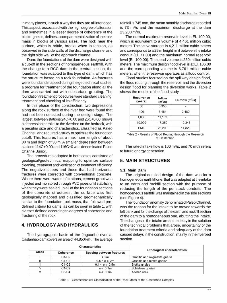
Flood studies focused on the spillway design flood,the flood routing through the reservoir and the diversiondesign flood for planning the diversion works. Table 2shows the results of the flood study.
Table 1 - Geomechanical Classification of the Rock Mass of the Castanhão Complex
Table 2 - Results of Flood Routing through the Reservoirof Castanhão.
The rated intake flow is 100 m3/s, and 70 m3/s refersto future energy generation.
5. MAIN STRUCTURES
5.1. Main DamThe original detailed design of the dam was for a
homogeneous earthfill one, that was adapted at the intaketo an earth and rockfill section with the purpose ofreducing the length of the penstock conduits. Thehomogeneous earthfill was maintained in the side sections(see Figure 4).
The foundation anomaly denominated Paleo Channel,was the reason for the intake to be moved towards theleft bank and for the change of the earth and rockfill sectionof the dam to a homogeneous one, abutting the intake.The changes in the intake area, the delay in the solutionof the technical problems that arose, uncertainty of thefoundation treatment criteria and adequacy of the damcaused delays in the construction, mainly in the riverbedsection.

Main Brazilian Dams III
7 8
The solution consisted in a roller compacted concrete(RCC) structure in the central section with the purposeto accelerate the construction (see Figure 5). With thismodification the main dam consisted of a central RCCsection and right and left banks of homogeneous earthfillembankments.
The earthfill dam has a volume of 4,245 x 103 m3
of compacted soil, its crest is 10 m in width, the upstreamslope is 2.5H:1.0V and the downstream slope 2H:1V,the rockfill for drains, filters, transitions, rip-rap anddownstream slope protection, has a total volume of687 x 103 m3.
The RCC dam is 640 m long and was moved upstreamfrom the original dam axis because of the Paleo Channel.The crest of the RCC dam is 7.0 m wide.
In the RCC dam there is a 2.50 m wide x 3.50 m highdrainage gallery between stations 5+10 and 36.
Along the RCC dam foundation, a drainage curtaindownstream from the grout curtain was drilled at 4.0 mcenters, down to 30 m into the foundation rock.
In every contraction joint of the RCC dam, drains werelocated downstream from the water-stop seals to conveyeventual infiltrations from the crest down to the inspectionand drainage galleries.
On August 28th 2003 the last lift of RCC was pouredreaching El. 110.90 and the final 10 cm of the dam crestwere finished with conventional vibrated concrete reachingEl. 111.00.
The construction volume of the RCC dam was948.6 x 103 m3 of roller compacted concrete (RCC 1 andRCC 2) and 240.7 x 10³ m3 of conventional concrete.
5.2. DikesThere are nine saddle dikes, with a typical section
shown in Figure 6, located on the right bank. They arelow structures with the purpose of closing the reservoirin some low areas.
The crest of the dikes is at El. 111.00, with severaldifferent widths, 14.00 m at the interface with the BR-116highway (dike 8), 10.00 m at road accesses to the jobsiteand 6.00 m where there is only a dike with no roadaccess.
On the left bank, at the end of the dam, a fuse plugspillway dike was built on a natural saddle at El. 110.00,
Figure 4 - Homogeneous Earthfill Dam - Cross Section
Figure 5 - Roller Compacted Concrete Dam - Cross Section
as an additional safety feature that will be activated incase of floods that cannot be controlled by the damcontrol structures.
This dike was built with an inclined impervious core,resting on a sand shell, and if the reservoir overflows thedike crest (El. 110.00), it will be eroded away, increasingthe outflow capacity of the reservoir.
5.3. SpillwayThe spillway is located on the right side of the dam
and was designed for a 10,000 year flood, with amaximum discharge capacity of 17,350 m³/s, with thereservoir at El. 106.00.
This overflow structure has a Creager profile (see

Main Brazilian Dams III
7 9
Figure 6 - Typical Cross Section of the Saddle Dikes
Figure 7 and Photo 3) with a ski jump at the end,12 sluiceways and 12 tainter gates. The spillway lengthis 153.0 m long and the sill is at El. 95.00.
The design mixtures of the conventional and cooledconcrete have strengths of: 30, 20 and 15 MPa.
Lean concrete for filling out depressions at the baseof the structure, have strengths of 8 and 10 MPa.
The steel reinforcement was of CA-50 type and thetotal amount used for the Castanhão works was 3,800 t.
Rock excavations for the spillway totaled1.875 x 103 m³, which was used for concrete and rockfill
Figure 7 - Spillway - Cross Section
at the jobsite. The total amount of concrete used in thespillway was 116. 2 x 10³ m³.
5.4. Intake, Gallery and Valve HouseThe intake, gallery and valve house are structures
that control the flow through the dam and were built inaccordance with the final design, with the exception ofthe axis that was displaced due to the Paleo Channeland a lengthening of the gallery because of the changeof the dam section from rockfill to homogeneous earthfill.
The design of the hydraulic circuit which comprises

Main Brazilian Dams III
8 0
Photo 3 - Castanhão Spillway
the intake tower, penstocks, valve house (see Photo 4)has a maximum flow capacity of 100 m³/s and a minimumof 10 m³/s.
The intake structure, located on the right bank,consists of a vertical tower of reinforced concrete, with aheight of 64.50 m. It includes two parallel conduits thatare embedded under the dam, have a rated flow capacityof 100 m³/s and a sill at El. 57.00.
The original axis of the intake structure was shiftedfrom stake 122 to 124+ 8,00, because of the change ofthe dam type from rockfill to RCC, and the intake gallerywas embedded in the rollcrete body of the dam.
The gallery is composed by two structural concretecells which shelter two 3.70 m diameter steel penstocks.These conduits are 175,00 m long and are supported byconcrete anchor blocks.
The valve house is located downstream from the rightbank dam and will be embodied in the future powerhouse,it shelters four 1.50 m diameter dispersion valves. Thehouse structure consists partly of overhead longitudinaland transverse frames and of an embedded structure,where the valves are fixed. The concrete volume of thisstructure is 70.008 m³ and the reinforcing CA-50 steelamounts to 3.074 t.
6. CONSTRUCTION
The decision to build the dam was consolidated whenthe government issued the tender documents, through
Photo 4 - Water Intake
DNOCS, for the construction of Castanhão dam. Bidswere opened in December 1989, and Construtora AndradeGutierrez S.A. won the contract.
At the end of 1995 the construction started with workbeing done to install the jobsite, build the access road,land clearing and foundation excavation of the dikes, damand spillway.
Supervision, technical assistance and inspection ofthe dam construction was the responsibility of theconsortium AGUASOLOS/HIDROTERRA.
In mid 1996 with the discovery of the Paleo Channel(see Photo 5), complementary geotechnical studies were

Main Brazilian Dams III
8 1
required, with core and percussion drilling, Dutch cone(Federal University of Ceará) and seismic refraction(Institute of Technological Research of São Paulo - IPT).
In parallel with the geotechnical studies, and with thedelays in the construction schedule due to the occurrenceof the paleo channel depression and the need to finishthe dam construction, the Secretariat of HydraulicResources of the State of Ceará - SRH hired theMontgomery - Watson - Engesoft Consortium to designthe central section of the dam in RCC.
In September 1999 work started on excavations,dewatering of the foundations and building the cofferdamsto be able to treat the foundations of the RCC dam.
Photo 6 shows work being carried out in the centralsection and at the interface between the earthfill damand the RCC dam abutment.
In January of 2003 the most important constructionworks being carried out were stopped because of a lackof financial resources.
The work was retaken after June 2003 when theMinistry of National Integration and the Government ofthe State of Ceará granted the funds needed for theconclusion of the works, which were accepted assubstantially finished on October 31 of 2003.
Photo 5 - Excavation of the Paleo Channel in the Riverbed
Photo 6 - Construction of the Interface between Earthfill Damand RCC Dam
7. ENVIRONMENTAL, SOCIAL ANDECONOMICAL ASPECTS
The impact of the development in an area of68,000 ha affected 1,981 rural proprietors, 696 urbanbuildings in the city of Jaguaribara and the district ofPoço Comprido that were both totally submerged by thereservoir, and part of the city of Jaguaretama (up toEl. 106.00). The registered owners were paid acompensation and in the process of resettlement theurban center of the town of Jaguaribara and the district ofPoço Comprido were reconstructed. The urbanresettlement covered a total of 1,044 families.
In the rural area the resettlement included implantingprojects, as irrigation (Curupati, Alagamar andMandacaru), fish farming (Curupati Peixe) andsettlements in a rainsed area. The resettled inhabitantsin these areas numbered in all, 833 families, and wereselected in accordance with criteria of capacity anddecision making in diversified projects that wereeconomically and environmentally sustainable.
Environmental protection rules prescribed in theEnvironmental Impact Report for Castanhão were: urbanresettlements (Jaguaribara); supervision of seismicity;establishment of fishing and fish farm projects;resettlement of rural populations; zoning areas fordeforestation around the reservoir; removal/relocation ofexisting infrastructure; establishment of seweragetreatment systems in the cities of Jaguaribe andJaguaretama; fauna management; studies to preserveflora and fauna from extinction; monitoring water, fromthe limnological - sanitary pont of view, monitoring of watertable; monitoring reservoir levels and sedimentation;establishment of two climatologic stations near thereservoir; environmental station project; monitoring of thereservoir protection area; recovery of the jobsite area,waste disposal and borrow areas; reactivation programof the economy, sanitation and public health andprotection of the city of Jaguaretama.
8. STRUCTURAL BEHAVIOR OF THEDAM
The instruments installed in Castanhão dam werebased on the design of an earthfill dam with instrumentsinstalled only in the central riverbed section. With thechange of the middle section to an RCC one, someadaptations were made on the original concept.
To observe the maximum temperature rise in the RCCdam, both in the middle of the mass and near the outersurface, a section with four lines of thermometers weredistributed along the height of the dam. The electric cableswere passed through conduits that ran up the downstreamslope to access gallery nº 2 where there is a readoutterminal. Temperatures were taken during theconstruction phase of the RCC dam.

Main Brazilian Dams III
8 2
To check uplift pressures at the concrete - rockinterface of the foundation, sixteen open pipe piezometerswere installed in six sections along the drainage gallery.In one transverse section at gallery nº 2 there are fourpiezometers.
A total of sixteen triorthogonal joint meters wereinstalled between blocks along the drainage gallery, andthree in the spillway blocks that have larger differencesin the foundation levels, with the purpose of measuringdisplacements along the three axes, and fixed to thestructures with anchor bars on both sides of the joints.
A geodesic survey system with twelve targets locatedon the central part of the crest at 50 m centers is intendedto monitor the vertical settlements that may occur alongthe concrete dam. For reference, two benchmarks wereinstalled on both banks, totaling 14 benchmarks.
Staff gages were installed at the DNOCS boatanchorage for obtaining data on the reservoir level.The daily difference in measurements furnish the volumeand daily inflow to the reservoir.
9. TECHNICAL FEATURES
GeneralLocation Jaguaribe RiverConstruction start 1995Construction finish 2003Owner DNOCSDesign Consortium Hidroservice/A.NoronhaContractor/Manufacturers/Erector Construtora
Andrade Gutierrez S.A./ALSTOM
Basic dataBasin área 44.850 km²Annual precipitation 745 mmAnnual evaporation (potential) 1.990 mm
ReservoirArea (at El. 100) 325 km²Storage volume (at El.106) 6.761.000.000 m3
Storage volume (at El.100) 4.461.000.000 m3
Active Storage (from El. 71 to 100 ) 4.211.000.000 m3
Dead volume (from El. 51 to 71) 250.000.000 m3
Flood detention storage (from El.100,00 to 106,00)2.300.000.000 m3
Maximum length 48 kmMaximum width 23 kmAverage width 8,75 kmMaximum normal W.L. (flood detention) 106,00Maximum normal W.L. (flow regulation) 100,00Maximum flood W.L. 108,80Minimum normal W.L. (flow regulation) 71,00
Flows
Mean Flow 73 m3/sMaximum recorded 23.200 m³/sMinimum recorded (monthly average) 0,2 m3/sMaximum InflowsMaximum Probable Flood (MPF) 23.200 m3/s10,000 Year Flood 17.350 m³/sDiversion Inflow (100 year recurrence) 6.484 m3/sCorresponding outflow 2.480 m3/s10,000 Year Flood routing at El.106Maximum inflow 17.350 m3/sMaximum outflow 14.820 m3/sMaximum flood elevation 108,80
Main DamType Homogeneous earth/RCCCrest length 3,410 m Earth/640 m RCCMaximum height over foundations 72 m (RCC)Crest elevation 111Width at crest 10,00 m earth/7,00m RCC
Auxiliary Dams - DikesType Homogeneous earthQuantity 9Maximum height 18 mLength 3.980 mCrest elevation 111,00
SpillwayType SurfaceLocation Right bankWidth 153 mCapacityMaximum discharge (10,000 year flood) 14.820 m3/sNappe height 11 mSill elevation 95,00GatesType Tainter GatesQuantity 12Size: Width 10 mSize:Height 11.5 mManufacturer ALSTOMRaising and lowering speed 0.5 m/min
IntakeLocation Right bankType TowerMaximum height 64.50 mFirm design flow 22.00 m3/sSill elevation 57.00 mRated Capacity 100 m3/s

Main Brazilian Dams III
8 3
PenstocksLocation Under the dam as conduits
embedded in 6.5 m square concrete cellsLength (3.70m diameter) 175 mLength of section (2.50 m diameter) 3.00 mMaterial ASTM A 516 grade 60 steel
Valve HouseType concrete structureLocation right bankEnergy Dissipation 4 dispersion valvesValve diameter 1,50 m
Hydroelectric Powerplant (future installation)Location right bankTurbine type KaplanTotal power capacity 22,5 MwNumber of units 2Design head 38,50 mMaximum head 50,00 mMinimum head 25,00 mNominal flow 70,00 m3/s
Construction Material QuantitiesCommon excavation 2,771,608 m3
Rock Excavation 1,874,960 m3
Main DamSoil 4,244,955 m3
Rockfill 687,160 m3
Cofferdams 105,600 m3
Concrete RCC 426,870 m3
Concrete (Conventional) 948,596 m³Reinforcement Steel 5,467 t
10. BIBLIOGRAPHY
[1] ARAÚJO, M.Z.T.; PONTE, A.T.M.M.S.;MALVEIRA, V.T.C.; AZEVEDO, R.V. Barragens doNordeste do Brasil (Dams of the Northeast of Brazil)3 ed. Fortaleza: DNOCS, 2003. 01 CD ROM.
[2] DNOCS. Estudos de impacto ambiental do projetoda barragem Castanhão (Environmental Impact ofCastanhão Development). Fortaleza: DNOCS, 1990.
[3] DNOCS. Relatório técnico final as built.(TechnicalReport "As Built") Fortaleza: DNOCS, 2004.263 p.
[4] LIMA, F.P.F. Castanhão: Do Sonho à Realidade(Castanhão: A Dream Come True) Fortaleza: ExpressãoGráfica .2007.273 p.
