ug-actuator - rtd-universal · the base is designed to fit any drive designed for a ug governor....
TRANSCRIPT

Product Manual 37512(Revision H)
Original Instructions
UG-Actuator
Installation and Operation Manual

DEFINITIONS
This is the safety alert symbol. It is used to alert you to potential personal injury hazards. Obey all safety messages that follow this symbol to avoid possible injury or death.
DANGER—Indicates a hazardous situation which, if not avoided, will result in death or serious injury.
WARNING—Indicates a hazardous situation which, if not avoided, could result in death or serious injury.
CAUTION—Indicates a hazardous situation which, if not avoided, could result in minor or moderate injury.
NOTICE—Indicates a hazard that could result in property damage only (including damage to the control).
IMPORTANT—Designates an operating tip or maintenance suggestion.
The engine, turbine, or other type of prime mover should be equipped with an overspeed shutdown device to protect against runaway or damage to the prime mover with possible personal injury, loss of life, or property damage.
The overspeed shutdown device must be totally independent of the prime mover control system. An overtemperature or overpressure shutdown device may also be needed for safety, as appropriate.
Read this entire manual and all other publications pertaining to the work to be performed before installing, operating, or servicing this equipment. Practice all plant and safety instructions and precautions. Failure to follow instructions can cause personal injury and/or property damage.
This publication may have been revised or updated since this copy was produced. To verify that you have the latest revision, be sure to check the Woodward website:
www.woodward.com/pubs/current.pdf The revision level is shown at the bottom of the front cover after the publication number. The latest version of most publications is available at:
www.woodward.com/publications If your publication is not there, please contact your customer service representative to get the latest copy.
Any unauthorized modifications to or use of this equipment outside its specified mechanical, electrical, or other operating limits may cause personal injury and/or property damage, including damage to the equipment. Any such unauthorized modifications: (i) constitute "misuse" and/or "negligence" within the meaning of the product warranty thereby excluding warranty coverage for any resulting damage, and (ii) invalidate product certifications or listings.
To prevent damage to a control system that uses an alternator or battery-charging device, make sure the charging device is turned off before disconnecting the battery from the system.
To prevent damage to electronic components caused by improper handling, read and observe the precautions in Woodward manual 82715, Guide for Handling and Protection of Electronic Controls, Printed Circuit Boards, and Modules.
Revisions—Text changes are indicated by a black line alongside the text. Woodward Governor Company reserves the right to update any portion of this publication at any time. Information provided by Woodward Governor Company is believed to be correct and reliable. However, no responsibility is assumed by Woodward Governor Company unless otherwise expressly undertaken.
© Woodward 1992 All Rights Reserved

Manual 37512 UG-Actuator
Woodward i
Contents
REGULATORY COMPLIANCE ........................................................................ III
CHAPTER 1. GENERAL INFORMATION ........................................................... 1 Introduction ............................................................................................................. 1 Description .............................................................................................................. 1 Available Terminal Shafts and Drive Shafts ........................................................... 2 UG Governor Similarities ........................................................................................ 3 Hydraulic Pump ...................................................................................................... 3 References ............................................................................................................. 3
CHAPTER 2. INSTALLATION.......................................................................... 8 Introduction ............................................................................................................. 8 Receiving ................................................................................................................ 8 Storage ................................................................................................................... 8 Drive Shaft Rotation ............................................................................................... 8 Attitude .................................................................................................................... 9 Mounting Dimension ............................................................................................... 9 Drive Connection .................................................................................................... 9 Remote Actuator Oil Connection .......................................................................... 10 Control Linkage .................................................................................................... 10 Oil Supply ............................................................................................................. 12 Electrical Connection ............................................................................................ 14 Heat Exchanger Selection .................................................................................... 15
CHAPTER 3. INITIAL OPERATION ................................................................ 17
CHAPTER 4. PRINCIPLES OF OPERATION ................................................... 18 Introduction ........................................................................................................... 18 Increase in Load or Speed Setting ....................................................................... 18 Decrease in Load or Speed Setting ..................................................................... 19 Loss of Control Voltage ........................................................................................ 19
CHAPTER 5. SERVICE OPTIONS ................................................................. 20 Product Service Options ....................................................................................... 20 Woodward Factory Servicing Options .................................................................. 21 Returning Equipment for Repair ........................................................................... 21 Replacement Parts ............................................................................................... 22 Engineering Services ............................................................................................ 22 How to Contact Woodward ................................................................................... 23 Technical Assistance ............................................................................................ 23
UG-ACTUATOR CONTROL SPECIFICATIONS ............................................... 25

UG-Actuator Manual 37512
ii Woodward
Illustrations and Tables Figure 1-1. The UG-Actuator .................................................................................. 1 Figure 1-2. Outline Drawing of UG-Actuator .......................................................... 4 Figure 1-3. Remote Mounted Actuator ................................................................... 5 Figure 1-4. Drive Shaft and Terminal Shaft Configurations ................................... 6 Figure 1-5. Schematic of UG-Actuator ................................................................... 7 Figure 2-1. Alignment of Reference Notch and Arrow ............................................ 9 Figure 2-2. Terminal Shaft Travel ......................................................................... 11 Figure 2-3. Linear Linkage .................................................................................... 11 Figure 2-4. Nonlinear Linkage .............................................................................. 11 Figure 2-5. Oil Chart ............................................................................................. 13 Figure 2-6. Viscosity Comparisons ....................................................................... 14 Figure 2-7a. Wiring for a UG-Actuator .................................................................. 15 Figure 2-7b. Wiring for a UG-Actuator with LVDT ................................................ 16 Figure 2-8. UG-Actuator Heat Exchanger ............................................................ 16

Manual 37512 UG-Actuator
Woodward iii
Regulatory Compliance The UG Actuator is suitable for use in Class I, Division 2, Groups A, B, C, and D per CSA for Canada or non-hazardous locations only. Wiring must be in accordance with North American Class I, Division 2 wiring methods as applicable, and in accordance with the authority having jurisdiction. These listings are limited only to those units bearing the CSA agency identification.
EXPLOSION HAZARD—Do not remove covers or connect/disconnect electrical connectors unless power has been switched off or the area is known to be non-hazardous. Substitution of components may impair suitability for Class I, Division 2.
RISQUE D’EXPLOSION—Ne pas enlever les couvercles, ni raccorder / débrancher les prises électriques, sans vous en assurez auparavant que le système a bien été mis hors tension; ou que vous vous situez bien dans une zone non explosive. La substitution de composants peut rendre ce matériel inacceptable pour les emplacements de Classe I, Division 2.

UG-Actuator Manual 37512
iv Woodward

Manual 37512 UG-Actuator
Woodward 1
Chapter 1. General Information
Introduction This manual describes the installation and operation of the UG-Actuator.
Figure 1-1. The UG-Actuator
Description The UG-Actuator is a proportional electro-hydraulic actuator which can be used with electronic controls which provide a 20 to 160 mA position signal. The actuator is designed for use with Woodward 2301, 400, 43027, 500-series, and 700-series controls. The actuator converts a given electrical signal to an output shaft position through the action of a torque motor and follower-type pilot valve. The rotary output actuator has 42 degrees of terminal (output) shaft travel. Recommended travel from the no-load to the full-load position is 2/3 of full actuator travel. The UG-Actuator is used on diesel, gas, and gasoline engines (also steam and industrial gas turbines) to replace UG-8 type governors, providing the advantages of electronic control and load sharing systems with the convenience of the existing UG-8 type drive and linkage.

UG-Actuator Manual 37512
2 Woodward
The standard UG-Actuator provides a maximum work capacity of 19.4 J (14.3 ft-lb) in the increase direction, and 23.3 J (17.2 ft-lb) in the decrease direction. A special actuator is available which provides 27.1 J (20.0 ft-lb) of work in both directions. Another special actuator is the remote actuator which does not have a drive shaft. Pressurized oil (758–2758 kPa/110–400 psi) must be supplied to the actuator. The remote actuator has 27.1 J (20.0 ft-lb) when supplied with 2758 kPa/400 psi. Work capacity is based on the full 42 degree travel of the terminal (output) shaft. Rated work capacity is 2/3 of maximum work capacity. The actuator can be built with a low speed pump for speed ranges of 375 to 1100 rpm, or with a high speed pump for 600 to 1500 rpm. The UG-Actuator is available with an LVDT for position feedback. The LVDT is not available with the MPU option. With the LVDT, the actuator has a 10-pin connector on the cover. The actuator may be equipped with a special gear and magnetic pickup, using the governor drive to sense engine speed. This permits an added convenience when converting from a UG hydraulic-mechanical governor to an electronic control system. Low cranking speeds may require override of the electronic failsafe. The MPU option is not available with the 27.1 J (20.0 ft-lb) work capacity UG-Actuator.
The MPU will sense the speed of the governor drive, which is not necessarily the same rpm as the engine. The frequency sensed by the MPU must match the frequency range of the electronic control.
The UG-Actuator output is directly proportional to a 20 to 160 mA signal from an electronic control system. This manual provides outline drawings to show the base and drive configurations. The outline drawings include information on electrical wiring, installation dimensions, drive requirements, oil requirements, and output shaft dimensions. The drawings are provided for reference only. Do not use the drawings for construction.
Available Terminal Shafts and Drive Shafts The following terminal shafts and drive shafts are available: Standard— 0.500–36 serrated terminal shaft (0.625–36 serrated for the 20 ft-lb model) 0.625–36 serrated drive shaft Available (for special applications at additional cost)— Terminal Shafts— 0.562 / 0.625 D-shaped terminal shaft 0.500–36 serrated terminal shaft with one missing serration 0.500–36 serrated terminal shaft on RH or LH side only

Manual 37512 UG-Actuator
Woodward 3
Keyed Drive Shafts— 0.750–6 splined drive shaft 1.125–48 serrated drive shaft [with PG-style base adapter] French standard BNA 227 NF-E22-151 0.16-31 drive shaft RHD6 drive shaft 0.625 keyed drive shaft with 0.625-18 thread Extended 0.625 keyed drive shaft
UG Governor Similarities The UG-Actuator uses the same cast-iron case as the UG governor. The standard UG output shaft, power lever, power piston, and piston link are used in the actuator. The base is designed to fit any drive designed for a UG governor.
Hydraulic Pump The UG-Actuator is equipped with a Gerotor pump (3161 governor type). High speed and low speed pumps are available, depending on the drive speed from the engine. The pump uses oil from the self-contained UG-Actuator sump to provide 1172 kPa (170 psi) internal operating pressure. The direction of rotation is selected by pump housing alignment. The pump operates in one direction only. The drive uses a maximum of 375 W (0.5 hp). In some cases the actuator may require an oil cooler to operate at the high end of the drive speed range.
References The following publications provide additional information about installation, operation, and storage of Woodward products. All are available on the Woodward website (www.woodward.com). Publication 25071 Oils for Hydraulic Controls 25075 Commercial Preservation Packaging for Storage of Mechanical-
Hydraulic Controls 50516 Governor Linkage for Butterfly Control Valve 37511 UG-Actuator Product Specification This manual does not attempt to provide information about the electronic control which determines the position of the UG-Actuator output. This information must be obtained from the appropriate manual for the electronic control. Contact your nearest Woodward Distributor or Authorized Independent Service Facility about repairs.

UG-Actuator Manual 37512
4 Woodward
Figure 1-2. Outline Drawing of UG-Actuator

Manual 37512 UG-Actuator
Woodward 5
Figure 1-3. Remote Mounted Actuator

UG-Actuator Manual 37512
6 Woodward
Figure 1-4. Drive Shaft and Terminal Shaft Configurations

Manual 37512 UG-Actuator
Woodward 7
Figure 1-5. Schematic of UG-Actuator
UG-Actuator Manual 37512
8 Woodward
Chapter 2. Installation
Introduction This chapter describes receiving, storage, and installation requirements for the UG-Actuator. Use care while handling and installing the UG-Actuator. Be particularly careful to avoid striking the drive shaft, terminal shaft, or the electrical connector. Abuse can damage seals, internal parts, and factory adjustments. Do not set the actuator on its drive shaft.
Receiving After factory testing and calibration, the UG-Actuator is drained of oil. This leaves a light film of oil on internal parts to prevent rust. External parts are painted or coated with a spray lubricant/rust inhibitor. No internal cleaning or flushing is necessary before installation and operation. The little oil left in the actuator is clean, multi-viscosity engine oil which will not contaminate the oil selected to operate the actuator. Fill the actuator with 1.4 liters (1.5 quarts) of oil selected to match the expected operating conditions. (If the actuator is a direct replacement for a UG governor, you may use the same grade and weight of oil that was being used in the governor.) Use only new, clean oil in the actuator. Do not allow dirt or contamination to enter the actuator while filling with operating oil. Do not use oil drained from the UG governor.
Storage The UG-Actuator may be stored for short periods of time (less than a year) as received from the factory. For long-term storage (more than a year), storage in an environment with large temperature changes, humid or corrosive atmosphere, etc., or if the actuator is installed on the engine for storage, fill the actuator with oil and follow preservation packaging instructions in Woodward manual 25075, Commercial Preservation Packaging for Storage of Mechanical-Hydraulic Controls.
Drive Shaft Rotation The actuator drive-shaft rotation is one direction only. Rotation, as viewed from the top of the actuator, must be the same as that of the engine drive when looking down on the mounting pad. If the actuator oil pump is rotated in the wrong direction, oil pressure will not be generated in the actuator.
Be sure engine mounting-pad drive and actuator-drive rotation are the same. Incorrect drive rotation will cause the actuator to become inoperative, and may cause actuator damage.

Manual 37512 UG-Actuator
Woodward 9
Figure 2-1. Alignment of Reference Notch and Arrow Use the following procedure to change the direction of rotation: 1. Remove the four pump-housing screws. 2. Index the pump plate 180 degrees to align the arrow corresponding to the
direction of rotation selected with the reference notch in the base. 3. Replace the four screws, and torque the screws to 16.4–17.5 N·m (145–155
lb-in). 4. Make sure that the actuator drive shaft rotates freely.
Attitude The UG-Actuator can be installed in a vertical or near vertical position without affecting its calibration. Do not install more than 45 degrees from vertical. See the outline drawing for installation instructions and dimensions.
Mounting Dimension When using the o-ring supplied with the actuator to seal between the actuator and actuator mounting pad on the engine, the mounting hole should have dimensions of 82.7–83.2 mm (3.255–3.275 inches) in order to provide the correct amount of squeeze on the o-ring. The mounting hole must be concentric with the drive in order to avoid side-loading the actuator drive shaft.
Drive Connection Make sure the actuator drive shaft turns freely before installing the actuator. The drive gear or coupling must slip freely into the governor drive of the engine. Do not apply external force. The drive must be free of binding, side load, or excess end-play. Improper alignment or fit between the parts can result in excessive wear or actuator-drive seizure.

UG-Actuator Manual 37512
10 Woodward
Mount the actuator squarely on the mounting pad. Torque the mounting bolts evenly. There can be no movement or rocking of the actuator on the engine-mounting pad.
Remote Actuator Oil Connection If the UG-Actuator is remotely installed, oil supply is through the side of the base mounting plate (Figure 1-3). Connect the external pressure supply to one of the two .250–18 NPTF ports in the base mounting plate. The oil supply line should be fitted with a 20–25 µm filter. The oil supply pressure must be at least 758 kPa (110 psi). A pressure of 2758 kPa (400 psi) will be required for 27 J (20 ft-lb) of output. The remote unit will require 1.9 L/min (0.5 US gal/min) at steady state and 9.5 L/min (2.5 US gal/min) transient response supply flow. Connect the return line to the .250–18 NPTF port in the top cover. Do not use the .125–27 connection in the base during operation. The actuator should be kept filled with oil for corrosion protection of internal parts.
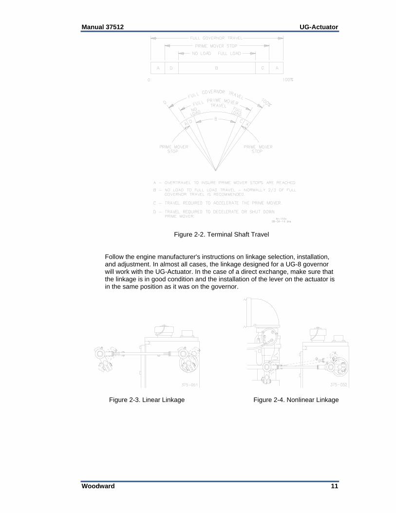
Control Linkage The terminal shaft rotates 42 degrees. Use 2/3 of the total rotation between no load and full load. The additional “overtravel” should be split and used at both ends to provide maximum fuel when required and to assure shutdown at minimum-fuel actuator position (see Figure 2-2).
To prevent possible serious injury or loss of life, or damage to the engine, be sure to allow sufficient overtravel at each end of the terminal shaft so the actuator can shut down the engine, and also give maximum fuel when required. Misadjusted linkage could prevent the actuator from shutting down the engine.
Many control problems are related to the linkage between the actuator and the engine. Use only first-quality rod ends for the linkage, rod ends that will last under the nearly constant motion associated with precise speed control. The linkage must be stiff, not subject to engine-caused vibration. The linkage must be as light as possible and still maintain the attributes of stiffness. Linkage which is too heavy can damage the actuator as well as make it difficult to achieve steady control. Installed linkages must operate smoothly, be free of binding, and free of lost motion due to worn parts. If there is a collapsible member in the linkage, be sure it does not yield each time the actuator moves the linkage rapidly. Use a linear linkage for most diesel applications. Most gasoline and gas fueled engines will require a non-linear linkage. See Figures 2-3 and 2-4 for information on the arrangements of linear and nonlinear connections. Linear linkage moves the fuel setting shaft in direct proportion to the movement of the actuator output. Nonlinear fuel arrangement lets the actuator open the fuel setting more at maximum settings than it does at minimum settings. Woodward application note 50516, Governor Linkage for Butterfly Throttle Valves, provides more information about non-linear linkage. Design the linkage so the power output of the engine is proportional to the position of the actuator output shaft.
Manual 37512 UG-Actuator
Woodward 11
Figure 2-2. Terminal Shaft Travel Follow the engine manufacturer's instructions on linkage selection, installation, and adjustment. In almost all cases, the linkage designed for a UG-8 governor will work with the UG-Actuator. In the case of a direct exchange, make sure that the linkage is in good condition and the installation of the lever on the actuator is in the same position as it was on the governor.
Figure 2-3. Linear Linkage
Figure 2-4. Nonlinear Linkage

UG-Actuator Manual 37512
12 Woodward
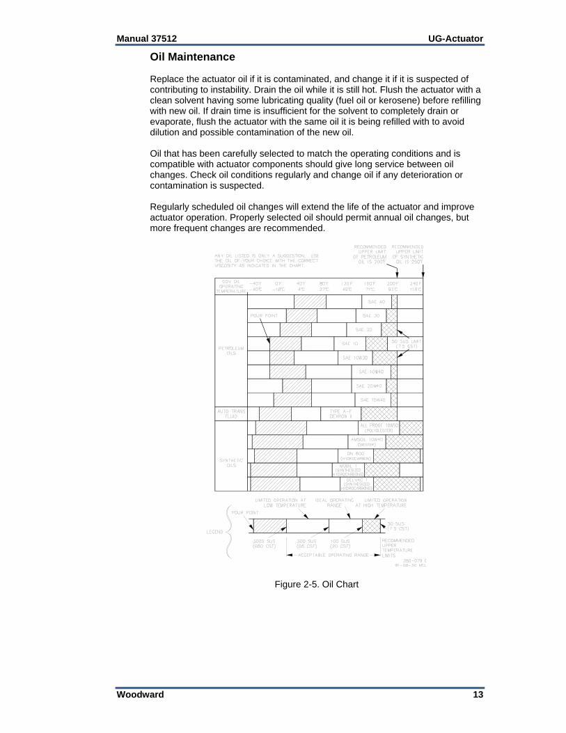
Oil Supply Use the information given in Figures 2-5 and 2-6 as a guide in the selection of a suitable oil. Oil grade selection is based on the operating temperature range of the actuator. Also use this information to aid in recognizing and correcting common problems associated with oil used in the actuator. Many operation and maintenance problems associated with UG-Actuators are directly related to the selection and condition of the oil in the actuator. Use care in the selection and make sure that the oil in the actuator is not contaminated. The oil in the UG-Actuator is both a lubricating and hydraulic oil. It must have a viscosity index that allows it to perform over the operating temperature range and it must have the proper blending of additives that cause it to remain stable and predictable over this range. The UG-Actuator is designed to give stable operation with most oils, if the fluid viscosity at the operating temperature is within a 50 to 3000 SUS (Saybolt Universal Seconds) range (see Figure 2-6). Poor actuator response or instability is an indication that the oil is too thick or too thin. Actuator oil must be compatible with seal material, that is, nitrile, polyacrylic, and fluorocarbon. Many automotive and gas engine oils, industrial lubricating oils, and other oils of mineral or synthetic origin meet these requirements. Fill the actuator with about 1.4 liters (1.5 quarts) of oil, to the mark on the oil sight glass. After the engine is started and the actuator is at operating temperature, add oil if necessary. Oil must be visible in the glass under all operating conditions. Excessive component wear or seizure in the actuator indicates the possibility of: 1. Insufficient lubrication caused by: an oil that flows slowly when it is cold, especially during start-up; no oil in the actuator. 2. Contaminated oil caused by: dirty oil containers; an actuator exposed to heating and cooling cycles, which created
condensation of water in the oil. 3. Oil not suitable for the operating conditions caused by: changes in ambient temperature; an improper oil level which creates foamy, aerated oil. Operating an actuator continuously beyond the high limit temperature of the oil will result in oil oxidation. This is identified by varnish or sludge deposits on the actuator parts. To reduce oil oxidation, lower the actuator operating temperature with a heat exchanger or other means, or change to an oil more oxidation-resistant at the operating temperature.
To prevent possible serious injury or loss of life, or damage to the engine, resulting from engine overspeed or a runaway engine, be sure to use only oil that falls within the 50 to 3000 SUS range. Using oils outside this range could cause the actuator to be unable to prevent a runaway engine.
Manual 37512 UG-Actuator
Woodward 13
Oil Maintenance Replace the actuator oil if it is contaminated, and change it if it is suspected of contributing to instability. Drain the oil while it is still hot. Flush the actuator with a clean solvent having some lubricating quality (fuel oil or kerosene) before refilling with new oil. If drain time is insufficient for the solvent to completely drain or evaporate, flush the actuator with the same oil it is being refilled with to avoid dilution and possible contamination of the new oil. Oil that has been carefully selected to match the operating conditions and is compatible with actuator components should give long service between oil changes. Check oil conditions regularly and change oil if any deterioration or contamination is suspected. Regularly scheduled oil changes will extend the life of the actuator and improve actuator operation. Properly selected oil should permit annual oil changes, but more frequent changes are recommended.
Figure 2-5. Oil Chart

UG-Actuator Manual 37512
14 Woodward
Figure 2-6. Viscosity Comparisons
EXPLOSION HAZARD—Do not remove covers or connect/disconnect electrical connectors unless power has been switched off or the area is known to be non-hazardous. Substitution of components may impair suitability for Class I, Division 2.
RISQUE D’EXPLOSION—Ne pas enlever les couvercles, ni raccorder / débrancher les prises électriques, sans vous en assurez auparavant que le système a bien été mis hors tension; ou que vous vous situez bien dans une zone non explosive. La substitution de composants peut rendre ce matériel inacceptable pour les emplacements de Classe I, Division 2.
Due to the hazardous location listings associated with this product, proper wire type and wiring practices are critical to operation.
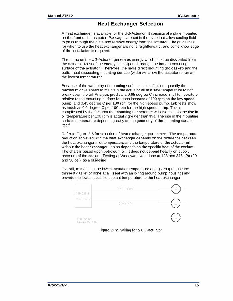
Do not connect any cable grounds to “instrument ground”, “control ground”, or any non-earth ground system. Make all required electrical connections based on the wiring diagrams (Figures 2-7a and 2-7b).
Electrical Connection The electrical connector on the UG-Actuator is a 3-pin (MS-3102E-14S-7P) plug connector. The LVDT version has a 10-pin connector (MS-3102E-18-1P or MS-3102R-18-1P).
Manual 37512 UG-Actuator
Woodward 15
Heat Exchanger Selection A heat exchanger is available for the UG-Actuator. It consists of a plate mounted on the front of the actuator. Passages are cut in the plate that allow cooling fluid to pass through the plate and remove energy from the actuator. The guidelines for when to use the heat exchanger are not straightforward, and some knowledge of the installation is required. The pump on the UG-Actuator generates energy which must be dissipated from the actuator. Most of the energy is dissipated through the bottom mounting surface of the actuator . Therefore, the more direct mounting (no gasket) and the better heat-dissipating mounting surface (wide) will allow the actuator to run at the lowest temperatures. Because of the variability of mounting surfaces, it is difficult to quantify the maximum drive speed to maintain the actuator oil at a safe temperature to not break down the oil. Analysis predicts a 0.65 degree C increase in oil temperature relative to the mounting surface for each increase of 100 rpm on the low speed pump, and 0.45 degree C per 100 rpm for the high speed pump. Lab tests show as much as 0.6 degree C per 100 rpm for the high speed pump. This is complicated by the fact that the mounting temperature will also rise, so the rise in oil temperature per 100 rpm is actually greater than this. The rise in the mounting surface temperature depends greatly on the geometry of the mounting surface itself. Refer to Figure 2-8 for selection of heat exchanger parameters. The temperature reduction achieved with the heat exchanger depends on the difference between the heat exchanger inlet temperature and the temperature of the actuator oil without the heat exchanger. It also depends on the specific heat of the coolant. The chart is based upon petroleum oil. It does not depend heavily on supply pressure of the coolant. Testing at Woodward was done at 138 and 345 kPa (20 and 50 psi), as a guideline. Overall, to maintain the lowest actuator temperature at a given rpm, use the thinnest gasket or none at all (seal with an o-ring around pump housing) and provide the lowest possible coolant temperature to the heat exchanger.
Figure 2-7a. Wiring for a UG-Actuator

UG-Actuator Manual 37512
16 Woodward
Figure 2-7b. Wiring for a UG-Actuator with LVDT
Figure 2-8. UG-Actuator Heat Exchanger

Manual 37512 UG-Actuator
Woodward 17
Chapter 3. Initial Operation
Before initial operation of the engine equipped with a UG-Actuator, read all of Chapter 2, Installation Procedures. Make sure that all installation steps have been correctly accomplished and all linkages are secured and properly attached. Carefully review the direction of rotation for the actuator oil pump. Follow this procedure when putting a new or repaired UG-Actuator into service. 1. Check that the actuator is full of the proper type and grade of clean oil. 2. Properly adjust the linkage.
To prevent possible serious injury or loss of life, or damage to the engine, be sure to allow sufficient overtravel at each end of the terminal shaft so the actuator can shut down the engine, and also give maximum fuel when required. Misadjusted linkage could prevent the actuator from shutting down the engine.
3. Select a LOW SPEED setting on the Woodward electronic control to give
low engine speed at initial start up.
Be prepared to make an emergency shutdown when starting the engine, turbine, or other type of prime mover, to protect against runaway or overspeed with possible personal injury, loss of life, or property damage.
4. Follow the engine manufacturer's instructions, and start the engine. 5. Adjust the selected speed setting on the Woodward electronic control as
necessary to bring the engine to rated speed. 6. Obtain system stability as outlined in the electronic control instruction
manual. (If less than the recommended actuator output stroke is used, it may cause for less than optimum engine stability or response.)
All operating adjustments of the UG-Actuator are made during factory calibration. Additional adjustment should not be needed.

UG-Actuator Manual 37512
18 Woodward
Chapter 4. Principles of Operation
Introduction This chapter describes the operation of the UG-Actuator. The schematic drawing in Figure 1-5 illustrates the working relationship of the various parts. Connecting oil passages between components are simplified for ease in visualizing the system. The UG-Actuator contains its own sump. The UG-Actuator consists of the following basic components: 1. Oil Pump Gerotor pump. Pump is driven by the actuator drive shaft. 2. Relief Valve Set to maintain internal operating pressure at 1172 kPa (170 psi). 3. Oil Filter Filters oil to the pilot valve to prevent contamination of the orifice and
nozzle. Bypass oil flows through the filter, providing a filter-cleaning function. 4. Torque Motor, Torque Motor Beam, Feedback Spring, and Loading Spring Used to establish a mechanical position of the pilot valve flapper in
response to the dc current being sent to the actuator. 5. Pilot Valve Plunger A follower-type valve, which duplicates the movement of the torque-motor
beam, but at a much higher force level, controls flow of oil to and from the servo. The pressure regulator is used to minimize calibration shifts due to speed-induced pump pressure changes.
6. Power Piston, Terminal Lever, and Terminal Shaft The terminal lever converts the linear motion of the differential-type servo
piston to rotary motion of the terminal shaft, which in turn moves the fuel linkage. The terminal-shaft position is fed back to the torque-motor beam to provide the proportional control.
Increase in Load or Speed Setting An increase in load, or speed setting, causes an increase in control current from the electronic control to the torque motor. This, in turn, causes an increase in the torque-motor force, tending to lower the centering adjustment end of the torque motor beam. The flow of oil through the nozzle is decreased, which increases pressure on the top side of the differential power land. Pressure above the differential power land then moves the pilot-valve plunger down, or allows the plunger to follow the torque-motor beam as if they were one piece. Pressure oil is now directed to the underside of the servo piston, causing it to move upward, which rotates the terminal lever and terminal shaft in the increase-fuel direction.

Manual 37512 UG-Actuator
Woodward 19
As the terminal shaft rotates, the range adjustment and feedback linkage increases the feedback spring force, and cause the torque-motor beam to move away from the nozzle. As flow through the nozzle is less restricted, pressure decreases on the top side of the differential power land to start moving the pilot-valve plunger up. The terminal shaft and pilot-valve plunger movement continues until the increase in feedback-spring force equals the increase in force seen in the torque motor. When the pilot-valve control land is centered, all movement stops at the new position required to run the engine at the increased load or speed setting.
Decrease in Load or Speed Setting A decrease in load or speed setting causes a decrease in control current from the electronic control to the torque motor. This, in turn, causes a decrease in torque motor force, and raises the centering adjustment of the torque motor beam. The pilot valve follows the beam and uncovers the control port. Oil trapped under the servo piston escapes to drain, causing the servo piston to move downward and the terminal shaft to rotate in the decrease-fuel direction. As the terminal shaft rotates, the range adjustment and feedback linkage decrease the feedback-spring force. The terminal shaft rotates until the decrease in spring force equals the decrease in force in the torque motor, and the pilot-valve plunger is centered. This stops the servo piston and the actuator shaft in the new position needed to run the engine at the decreased load or speed setting.
Loss of Control Voltage Upon loss of control voltage, the actuator terminal shaft goes to minimum fuel, thus offering a safety feature. With loss of control voltage, there is no current sent to the torque motor and no magnetic force generated. The torque motor and attached beam and the force of the loading spring causes the center adjustment to raise. The pilot valve follows, keeping the control port uncovered. Trapped oil escapes to drain, and the servo piston moves down until it reaches minimum fuel position.

UG-Actuator Manual 37512
20 Woodward
Chapter 5. Service Options
Product Service Options If you are experiencing problems with the installation, or unsatisfactory performance of a Woodward product, the following options are available: Consult the troubleshooting guide in the manual. Contact the manufacturer or packager of your system. Contact the Woodward Full Service Distributor serving your area. Contact Woodward technical assistance (see “How to Contact Woodward”
later in this chapter) and discuss your problem. In many cases, your problem can be resolved over the phone. If not, you can select which course of action to pursue based on the available services listed in this chapter.
OEM and Packager Support: Many Woodward controls and control devices are installed into the equipment system and programmed by an Original Equipment Manufacturer (OEM) or Equipment Packager at their factory. In some cases, the programming is password-protected by the OEM or packager, and they are the best source for product service and support. Warranty service for Woodward products shipped with an equipment system should also be handled through the OEM or Packager. Please review your equipment system documentation for details. Woodward Business Partner Support: Woodward works with and supports a global network of independent business partners whose mission is to serve the users of Woodward controls, as described here:
A Full Service Distributor has the primary responsibility for sales, service, system integration solutions, technical desk support, and aftermarket marketing of standard Woodward products within a specific geographic area and market segment.
An Authorized Independent Service Facility (AISF) provides authorized service that includes repairs, repair parts, and warranty service on Woodward's behalf. Service (not new unit sales) is an AISF's primary mission.
A Recognized Engine Retrofitter (RER) is an independent company that does retrofits and upgrades on reciprocating gas engines and dual-fuel conversions, and can provide the full line of Woodward systems and components for the retrofits and overhauls, emission compliance upgrades, long term service contracts, emergency repairs, etc.
A Recognized Turbine Retrofitter (RTR) is an independent company that does both steam and gas turbine control retrofits and upgrades globally, and can provide the full line of Woodward systems and components for the retrofits and overhauls, long term service contracts, emergency repairs, etc.
A current list of Woodward Business Partners is available at www.woodward.com/support/directory.cfm.

Manual 37512 UG-Actuator
Woodward 21
Woodward Factory Servicing Options The following factory options for servicing Woodward products are available through your local Full-Service Distributor or the OEM or Packager of the equipment system, based on the standard Woodward Product and Service Warranty (5-01-1205) that is in effect at the time the product is originally shipped from Woodward or a service is performed: Replacement/Exchange (24-hour service) Flat Rate Repair Flat Rate Remanufacture Replacement/Exchange: Replacement/Exchange is a premium program designed for the user who is in need of immediate service. It allows you to request and receive a like-new replacement unit in minimum time (usually within 24 hours of the request), providing a suitable unit is available at the time of the request, thereby minimizing costly downtime. This is a flat-rate program and includes the full standard Woodward product warranty (Woodward Product and Service Warranty 5-01-1205). This option allows you to call your Full-Service Distributor in the event of an unexpected outage, or in advance of a scheduled outage, to request a replacement control unit. If the unit is available at the time of the call, it can usually be shipped out within 24 hours. You replace your field control unit with the like-new replacement and return the field unit to the Full-Service Distributor. Charges for the Replacement/Exchange service are based on a flat rate plus shipping expenses. You are invoiced the flat rate replacement/exchange charge plus a core charge at the time the replacement unit is shipped. If the core (field unit) is returned within 60 days, a credit for the core charge will be issued. Flat Rate Repair: Flat Rate Repair is available for the majority of standard products in the field. This program offers you repair service for your products with the advantage of knowing in advance what the cost will be. All repair work carries the standard Woodward service warranty (Woodward Product and Service Warranty 5-01-1205) on replaced parts and labor. Flat Rate Remanufacture: Flat Rate Remanufacture is very similar to the Flat Rate Repair option with the exception that the unit will be returned to you in “like-new” condition and carry with it the full standard Woodward product warranty (Woodward Product and Service Warranty 5-01-1205). This option is applicable to mechanical products only.
Returning Equipment for Repair If a control (or any part of an electronic control) is to be returned for repair, please contact your Full-Service Distributor in advance to obtain Return Authorization and shipping instructions. When shipping the item(s), attach a tag with the following information: return authorization number; name and location where the control is installed; name and phone number of contact person; complete Woodward part number(s) and serial number(s); description of the problem; instructions describing the desired type of repair.

UG-Actuator Manual 37512
22 Woodward
Packing a Control Use the following materials when returning a complete control: protective caps on any connectors; antistatic protective bags on all electronic modules; packing materials that will not damage the surface of the unit; at least 100 mm (4 inches) of tightly packed, industry-approved packing
material; a packing carton with double walls; a strong tape around the outside of the carton for increased strength.
To prevent damage to electronic components caused by improper handling, read and observe the precautions in Woodward manual 82715, Guide for Handling and Protection of Electronic Controls, Printed Circuit Boards, and Modules.
Replacement Parts When ordering replacement parts for controls, include the following information: the part number(s) (XXXX-XXXX) that is on the enclosure nameplate; the unit serial number, which is also on the nameplate.
Engineering Services Woodward offers various Engineering Services for our products. For these services, you can contact us by telephone, by email, or through the Woodward website. Technical Support Product Training Field Service Technical Support is available from your equipment system supplier, your local Full-Service Distributor, or from many of Woodward’s worldwide locations, depending upon the product and application. This service can assist you with technical questions or problem solving during the normal business hours of the Woodward location you contact. Emergency assistance is also available during non-business hours by phoning Woodward and stating the urgency of your problem. Product Training is available as standard classes at many of our worldwide locations. We also offer customized classes, which can be tailored to your needs and can be held at one of our locations or at your site. This training, conducted by experienced personnel, will assure that you will be able to maintain system reliability and availability. Field Service engineering on-site support is available, depending on the product and location, from many of our worldwide locations or from one of our Full-Service Distributors. The field engineers are experienced both on Woodward products as well as on much of the non-Woodward equipment with which our products interface. For information on these services, please contact us via telephone, email us, or use our website: www.woodward.com/support.
Manual 37512 UG-Actuator
Woodward 23
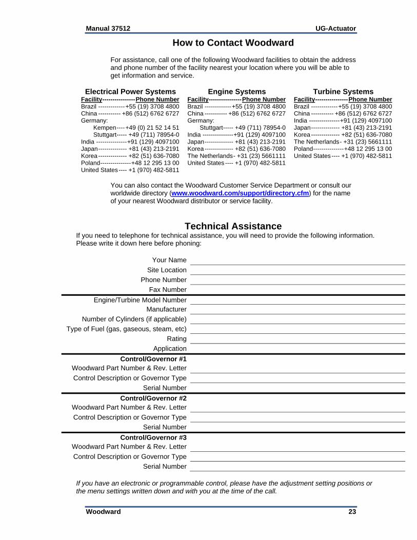
How to Contact Woodward For assistance, call one of the following Woodward facilities to obtain the address and phone number of the facility nearest your location where you will be able to get information and service.
Electrical Power Systems Facility ---------------- Phone Number Brazil ------------- +55 (19) 3708 4800 China ----------- +86 (512) 6762 6727 Germany: Kempen ---- +49 (0) 21 52 14 51 Stuttgart ----- +49 (711) 78954-0 India --------------- +91 (129) 4097100 Japan -------------- +81 (43) 213-2191 Korea -------------- +82 (51) 636-7080 Poland --------------- +48 12 295 13 00 United States ---- +1 (970) 482-5811
Engine Systems Facility ---------------- Phone Number Brazil ------------- +55 (19) 3708 4800 China ----------- +86 (512) 6762 6727 Germany: Stuttgart ----- +49 (711) 78954-0 India --------------- +91 (129) 4097100 Japan -------------- +81 (43) 213-2191 Korea -------------- +82 (51) 636-7080 The Netherlands - +31 (23) 5661111 United States ---- +1 (970) 482-5811
Turbine Systems Facility ---------------- Phone Number Brazil ------------- +55 (19) 3708 4800 China ----------- +86 (512) 6762 6727 India --------------- +91 (129) 4097100 Japan -------------- +81 (43) 213-2191 Korea -------------- +82 (51) 636-7080 The Netherlands - +31 (23) 5661111 Poland --------------- +48 12 295 13 00 United States ---- +1 (970) 482-5811
You can also contact the Woodward Customer Service Department or consult our worldwide directory (www.woodward.com/support/directory.cfm) for the name of your nearest Woodward distributor or service facility.
Technical Assistance If you need to telephone for technical assistance, you will need to provide the following information. Please write it down here before phoning:
Your Name
Site Location
Phone Number
Fax Number
Engine/Turbine Model Number Manufacturer
Number of Cylinders (if applicable)
Type of Fuel (gas, gaseous, steam, etc)
Rating
Application
Control/Governor #1 Woodward Part Number & Rev. Letter
Control Description or Governor Type
Serial Number
Control/Governor #2 Woodward Part Number & Rev. Letter
Control Description or Governor Type
Serial Number
Control/Governor #3 Woodward Part Number & Rev. Letter
Control Description or Governor Type
Serial Number
If you have an electronic or programmable control, please have the adjustment setting positions or the menu settings written down and with you at the time of the call.

UG-Actuator Manual 37512
24 Woodward
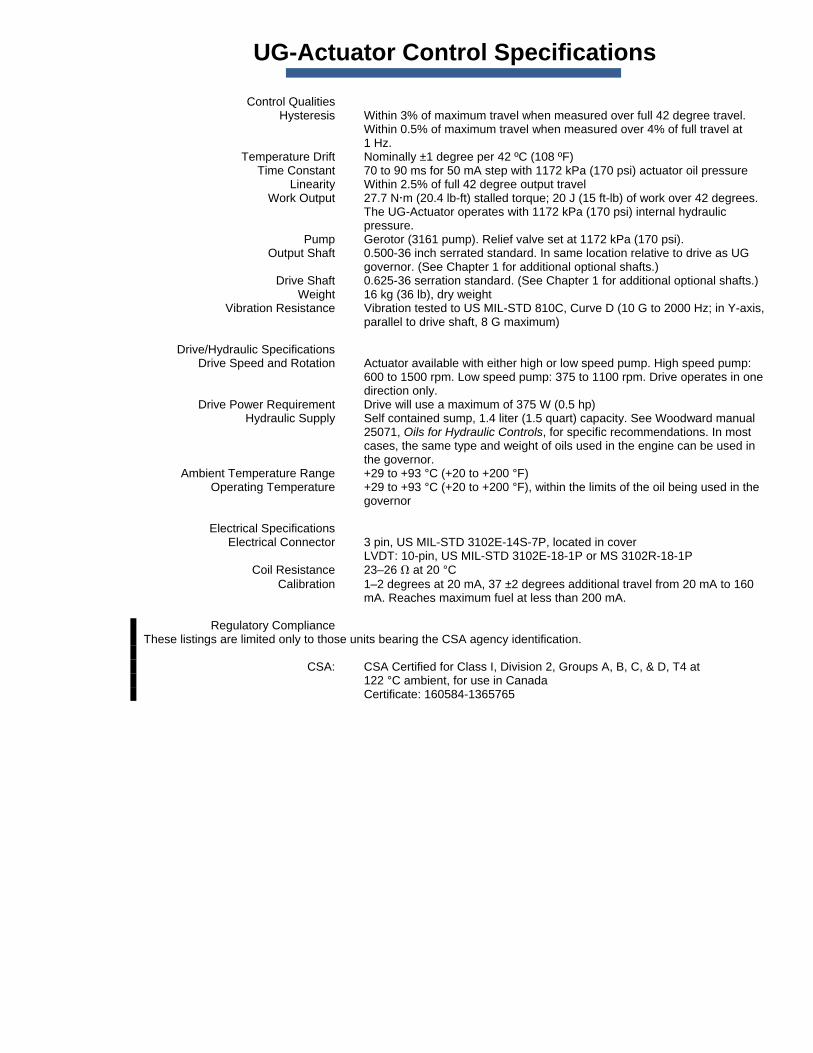
UG-Actuator Control Specifications Control Qualities Hysteresis Within 3% of maximum travel when measured over full 42 degree travel.
Within 0.5% of maximum travel when measured over 4% of full travel at 1 Hz.
Temperature Drift Nominally ±1 degree per 42 ºC (108 ºF) Time Constant 70 to 90 ms for 50 mA step with 1172 kPa (170 psi) actuator oil pressure Linearity Within 2.5% of full 42 degree output travel Work Output 27.7 Nm (20.4 lb-ft) stalled torque; 20 J (15 ft-lb) of work over 42 degrees.
The UG-Actuator operates with 1172 kPa (170 psi) internal hydraulic pressure.
Pump Gerotor (3161 pump). Relief valve set at 1172 kPa (170 psi). Output Shaft 0.500-36 inch serrated standard. In same location relative to drive as UG
governor. (See Chapter 1 for additional optional shafts.) Drive Shaft 0.625-36 serration standard. (See Chapter 1 for additional optional shafts.) Weight 16 kg (36 lb), dry weight Vibration Resistance Vibration tested to US MIL-STD 810C, Curve D (10 G to 2000 Hz; in Y-axis,
parallel to drive shaft, 8 G maximum) Drive/Hydraulic Specifications Drive Speed and Rotation Actuator available with either high or low speed pump. High speed pump:
600 to 1500 rpm. Low speed pump: 375 to 1100 rpm. Drive operates in one direction only.
Drive Power Requirement Drive will use a maximum of 375 W (0.5 hp) Hydraulic Supply Self contained sump, 1.4 liter (1.5 quart) capacity. See Woodward manual
25071, Oils for Hydraulic Controls, for specific recommendations. In most cases, the same type and weight of oils used in the engine can be used in the governor.
Ambient Temperature Range +29 to +93 °C (+20 to +200 °F) Operating Temperature +29 to +93 °C (+20 to +200 °F), within the limits of the oil being used in the
governor Electrical Specifications Electrical Connector 3 pin, US MIL-STD 3102E-14S-7P, located in cover LVDT: 10-pin, US MIL-STD 3102E-18-1P or MS 3102R-18-1P Coil Resistance 23–26 at 20 °C Calibration 1–2 degrees at 20 mA, 37 ±2 degrees additional travel from 20 mA to 160
mA. Reaches maximum fuel at less than 200 mA. Regulatory Compliance These listings are limited only to those units bearing the CSA agency identification. CSA: CSA Certified for Class I, Division 2, Groups A, B, C, & D, T4 at
122 °C ambient, for use in Canada Certificate: 160584-1365765

We appreciate your comments about the content of our publications.
Send comments to: [email protected]
Please reference publication 37512H.
PO Box 1519, Fort Collins CO 80522-1519, USA 1000 East Drake Road, Fort Collins CO 80525, USA Phone +1 (970) 482-5811 Fax +1 (970) 498-3058
Email and Website—www.woodward.com
Woodward has company-owned plants, subsidiaries, and branches, as well as authorized distributors and other authorized service and sales facilities throughout the world.
Complete address / phone / fax / email information for all locations is available on our website.
2011/1/Colorado