ufgs 25 10 10 utility monitoring and control system (umcs) · 2.2.2.5 ip router 2.3 computer...
TRANSCRIPT

**************************************************************************USACE / NAVFAC / AFCESA / NASA UFGS-25 10 10 (November 2008) -----------------------------Preparing Activity: USACE Superseding UFGS-25 10 10 (April 2006)
UNIFIED FACILITIES GUIDE SPECIFICATIONS
References are in agreement with UMRL dated January 2009**************************************************************************
SECTION TABLE OF CONTENTS
DIVISION 25 - INTEGRATED AUTOMATION
SECTION 25 10 10
UTILITY MONITORING AND CONTROL SYSTEM (UMCS)
11/08
PART 1 GENERAL
1.1 REFERENCES 1.2 DEFINITIONS 1.2.1 Application Specific Controller 1.2.2 Binary 1.2.3 Binding 1.2.4 Building Control Network 1.2.5 Building Point of Connection (BPOC) 1.2.6 Channel 1.2.7 Configuration Parameter 1.2.8 Control Logic Diagram 1.2.9 Domain 1.2.10 Explicit Messaging 1.2.11 External Interface File (XIF) 1.2.12 Functional Profile 1.2.13 Gateway 1.2.14 General Purpose Programmable Controller (GPPC) 1.2.15 LonMark Object 1.2.16 LNS Plug-in 1.2.17 LonMark 1.2.18 LonMark International 1.2.19 LonMark Interoperability Association 1.2.20 LonWorks 1.2.21 LonWorks Network Services (LNS) 1.2.22 Monitoring and Control (M&C) Software 1.2.23 Network Variable 1.2.24 Network Configuration Tool 1.2.25 Node 1.2.26 Node Address 1.2.27 Node ID 1.2.28 Program ID 1.2.29 Repeater 1.2.30 Router 1.2.31 Segment 1.2.32 Service Pin
SECTION 25 10 10 Page 1
1.2.33 Standard Configuration Parameter Type (SCPT) 1.2.34 Standard Network Variable Type (SNVT) 1.2.35 Subnet 1.2.36 TP/FT-10 1.2.37 UMCS Network 1.2.38 User-defined Configuration Parameter Type (UCPT) 1.2.39 User-defined Network Variable Type (UNVT) 1.3 SYSTEM DESCRIPTION 1.3.1 System Requirements 1.3.2 Symbols, Definition and Abbreviations 1.3.3 System Units and Accuracy 1.3.4 Work Coordination 1.3.5 Work Control 1.3.6 Working Hours 1.3.7 Equipment Repairs 1.3.8 Replacement, Modernization, Renovation 1.3.9 Access To UMCS Equipment 1.3.10 Records, Logs, and Progress Reports 1.4 SUBMITTALS 1.5 QUALITY ASSURANCE 1.5.1 UMCS IP Network 1.5.2 Service Call Reception 1.5.3 System Modifications 1.5.4 UMCS Contractor Design Drawings 1.5.5 As-Built Drawings 1.6 PROJECT/SITE CONDITIONS 1.7 PROJECT SEQUENCING 1.8 WARRANTY 1.9 MAINTENANCE AND SERVICE 1.9.1 Preventive Maintenance Requirements 1.9.1.1 Preventive Maintenance Work Plan 1.9.1.2 Semiannual Maintenance 1.9.1.3 Maintenance Procedures 1.9.2 Operation and Maintenance (O&M) Instructions
PART 2 PRODUCTS
2.1 EQUIPMENT REQUIREMENTS 2.1.1 Product Sourcing 2.1.2 Nameplates 2.1.3 Product Data Sheets 2.2 NETWORK HARDWARE 2.2.1 Building Point of Connection (BPOC) Hardware 2.2.1.1 CEA-709.1B TP/FT-10 to IP Router 2.2.1.2 CEA-709.1B Gateway 2.2.2 IP Network Hardware 2.2.2.1 Wire and Cables 2.2.2.2 Fiber Optic Patch Panel. 2.2.2.3 Fiber Optic Media Converter 2.2.2.4 Ethernet Switch 2.2.2.5 IP Router 2.3 COMPUTER HARDWARE 2.3.1 Server Hardware 2.3.2 Workstation Hardware (Desktop and Laptop) 2.3.3 Printers 2.3.3.1 Alarm Printer 2.3.3.2 Laser Printer 2.3.3.3 Color Printer 2.4 COMPUTER SOFTWARE
SECTION 25 10 10 Page 2
2.4.1 Operating System (OS) 2.4.2 Office Automation Software 2.4.3 Virus Protection Software 2.4.4 CEA-852-A Configuration Server 2.4.5 CEA-709.1B Network Configuration Tool 2.4.6 Monitoring and Control (M&C) Software 2.4.6.1 Passwords 2.4.6.2 Protocol Drivers 2.4.6.3 System Graphic Displays 2.4.6.4 Scheduling 2.4.6.5 Alarms 2.4.6.6 Trending 2.4.6.7 Electrical Power Demand Limiting 2.4.6.8 Demand Limiting with Real-Time Pricing 2.4.6.9 Programming Language 2.4.6.10 Report Generation 2.5 UNINTERRUPTIBLE POWER SUPPLY (UPS) 2.6 RACKS AND ENCLOSURES 2.6.1 Enclosures 2.6.2 Equipment Racks 2.7 FACTORY TEST
PART 3 EXECUTION
3.1 EXISTING CONDITIONS SURVEY 3.2 DRAWINGS AND CALCULATIONS 3.3 INSTALLATION REQUIREMENTS 3.3.1 General 3.3.2 Isolation and Penetrations of Buildings 3.4 INSTALLATION OF EQUIPMENT 3.4.1 Wire and Cable Installation 3.4.2 Grounding 3.4.3 Power-Line Surge Protection 3.4.4 Computer Hardware and Software 3.4.4.1 Hardware Installation 3.4.4.2 Software Installation 3.4.5 Network Hardware 3.4.6 IP Addresses 3.4.7 IP Network Installation 3.5 INTEGRATION OF BUILDING LEVEL CONTROLS 3.5.1 CEA-709.1B Systems 3.5.2 Legacy CEA-709.1B Systems 3.5.3 Legacy non-CEA-709.1B Systems via Gateway 3.5.4 Legacy non-CEA-709.1B Systems at M&C Server via Protocol Driver 3.6 START-UP AND START-UP TESTING 3.7 PERFORMANCE VERIFICATION TEST (PVT) 3.7.1 PVT Phase I Procedures 3.7.2 PVT Phase I 3.7.3 PVT Phase II 3.8 TRAINING 3.8.1 Training Documentation 3.8.2 Basic Operator Training 3.8.3 Advanced Operator Training 3.8.4 Operator Refresher Training
-- End of Section Table of Contents --
SECTION 25 10 10 Page 3
**************************************************************************USACE / NAVFAC / AFCESA / NASA UFGS-25 10 10 (November 2008) -----------------------------Preparing Activity: USACE Superseding UFGS-25 10 10 (April 2006)
UNIFIED FACILITIES GUIDE SPECIFICATIONS
References are in agreement with UMRL dated January 2009**************************************************************************
SECTION 25 10 10
UTILITY MONITORING AND CONTROL SYSTEM (UMCS)11/08
**************************************************************************NOTE: This guide specification covers the requirements for a Utility Monitoring and Control System (UMCS) based on open system technologies including the CEA-709.1B communication protocol and LonWorks Network Services (LNS).
Edit this guide specification for project specific requirements by adding, deleting, or revising text. For bracketed items, choose applicable items(s) or insert appropriate information.
Remove information and requirements not required in respective project, whether or not brackets are present.
Comments and suggestions on this guide specification are welcome and should be directed to the technical proponent of the specification. A listing of technical proponents, including their organization designation and telephone number, is on the Internet.
Recommended changes to a UFGS should be submitted as a Criteria Change Request (CCR).
Additional information and guidance on use of this guide specification is contained in ECB 2004-11, which may be found on the Internet on the TechInfo web site at: http://www.hnd.usace.army.mil/techinfo/ECbull.htm
**************************************************************************
PART 1 GENERAL
1.1 REFERENCES
**************************************************************************NOTE: This paragraph is used to list the publications cited in the text of the guide specification. The publications are referred to in
SECTION 25 10 10 Page 4

the text by basic designation only and listed in this paragraph by organization, designation, date, and title.
Use the Reference Wizard's Check Reference feature when you add a RID outside of the Section's Reference Article to automatically place the reference in the Reference Article. Also use the Reference Wizard's Check Reference feature to update the issue dates.
References not used in the text will automatically be deleted from this section of the project specification when you choose to reconcile references in the publish print process.
**************************************************************************
The publications listed below form a part of this specification to the extent referenced. The publications are referred to within the text by the basic designation only.
AMERICAN NATIONAL STANDARDS INSTITUTE (ANSI)
ANSI INCITS 154 (1988; R 2004) Office Machines and Supplies - Alphanumeric Machines-Keyboard Arrangement
AMERICAN SOCIETY OF HEATING, REFRIGERATING AND AIR-CONDITIONING ENGINEERS (ASHRAE)
ASHRAE FUN IP (2005) Fundamentals Handbook, I-P Edition
ASHRAE FUN SI (2005) Fundamentals Handbook, SI Edition
CONSUMER ELECTRONICS ASSOCIATION (CEA)
CEA-709.1B (2002) Control Network Protocol Specification
CEA-709.3 (1999) Free-Topology Twisted-Pair Channel Specification
CEA-852-A (2004) Tunneling Component Network Protocols Over Internet Protocol Channels
INSTITUTE OF ELECTRICAL AND ELECTRONICS ENGINEERS (IEEE)
IEEE C62.41.1 (2002) IEEE Guide on the Surges Environment in Low-Voltage (1000 V and Less) AC Power Circuits
IEEE C62.41.2 (2002) IEEE Recommended Practice on Characterization of Surges in Low-Voltage (1000 V and Less) AC Power Circuits
IEEE Std 100 (2000) The Authoritative Dictionary of IEEE Standards Terms
IEEE Std 802.1D (2004; Amendment 2004) Media Access
SECTION 25 10 10 Page 5
Control Bridges
IEEE Std 802.2 (1998; R 2003) Standards for Local Area Networks: Logical Link Control
IEEE Std 802.3 WARNING: Text in tags exceeds the maximum length of 300 characters
INTERNATIONAL ORGANIZATION FOR STANDARDIZATION (ISO)
ISO OSI Model Open Systems Interconnection Reference Model
LONMARK INTERNATIONAL (LonMark)
LonMark SNVT List (2002) LonMark SNVT Master List; Version 11 Revision 2
LonMark XIF Guide (2001) LonMark External Interface File Reference Guide; Revision 4.0B
NATIONAL ELECTRICAL MANUFACTURERS ASSOCIATION (NEMA)
NEMA 250 (2003) Enclosures for Electrical Equipment (1000 Volts Maximum)
NATIONAL FIRE PROTECTION ASSOCIATION (NFPA)
NFPA 262 (2006) Test for Flame Travel and Smoke of Wires and Cables for Use in Air-Handling Spaces
NFPA 70 (2007; AMD 1 2008) National Electrical Code - 2008 Edition
TELECOMMUNICATIONS INDUSTRY ASSOCIATION (TIA)
TIA J-STD-607-A (2002) Commercial Building Grounding (Earthing) and Bonding Requirements for Telecommunications
TIA/EIA-568-B.1 (2001 Addendums 2001, 2003, 2003, 2003, 2004, 2007) Commercial Building Telecommunications Cabling Standard - Part 1: General Requirements
TIA/EIA-606-A (2002) Administration Standard for the Telecommunications Infrastructure
THE INTERNET ENGINEERING TASK FORCE (IETF)
RFC 1112 (1989) Host Extensions for IP Multicasting (IGMP)
RFC 1371 (1992) Choosing a "Common IGP" for the IP Internet
RFC 1812 (1995) Requirements for IP Version 4 Routers
SECTION 25 10 10 Page 6

RFC 1918 (1996) Address Allocation for Private Internets
RFC 2131 (1997) Dynamic Host Configuration Protocol
RFC 2784 (2000) Generic Routing Encapsulation (GRE)
RFC 768 (1980) User Datagram Protocol (UDP)
RFC 791 (1981) Internet Protocol (IP)
RFC 792 (1981) Internet Control Message Protocol (ICMP)
RFC 793 (1981) Transmission Control Protocol (TCP)
RFC 821 (2001) Simple Mail Transfer Protocol (SMTP)
RFC 826 (1982) Ethernet Address Resolution Protocol (ARP)
U.S. DEPARTMENT OF DEFENSE (DOD)
MIL-STD-2202 (Rev A) Energy Monitoring and Control Systems, Factory Tests
U.S. FEDERAL COMMUNICATIONS COMMISSION (FCC)
FCC EMC (2002) FCC Electromagnetic Compliance Requirements
U.S. NATIONAL ARCHIVES AND RECORDS ADMINISTRATION (NARA)
47 CFR 15 Radio Frequency Devices
UNDERWRITERS LABORATORIES (UL)
UL 1778 (2005; Rev thru Jul 2006) Uninterruptible Power Systems
UL 60950 (2000; Rev thru Oct 2007) Safety of Information Processing and Business Equipment
UL 916 (2007) Energy Management Equipment
1.2 DEFINITIONS
The following list of definitions may contain terms not found elsewhere in this Section but are included here for completeness.
1.2.1 Application Specific Controller
A device that is furnished with a pre-established built in application that is configurable but not re-programmable. An ASC has a fixed factory-installed application program (i.e Program ID) with configurable settings.
SECTION 25 10 10 Page 7
1.2.2 Binary
A two-state system where an "ON" condition is represented by a high signal level and an "OFF" condition is represented by a low signal level. 'Digital' is sometimes used interchangeably with 'binary'.
1.2.3 Binding
The act of establishing communications between CEA-709.1B devices by associating the output of a device to the input of another.
1.2.4 Building Control Network
The CEA-709.1B control network installed under Section 23 09 23 DIRECT DIGITAL CONTROL FOR HVAC AND OTHER LOCAL BUILDING SYSTEMS consisting of a backbone and one or more local control busses.
1.2.5 Building Point of Connection (BPOC)
The BPOC is the point of connection between the UMCS network backbone (an IP network) and the building control network backbone. The hardware at this location, that provides the connection is referred to as the BPOC Hardware. In general, the term "BPOC Location" means the place where this connection occurs, and "BPOC Hardware" means the device that provides the connection. Sometimes the term "BPOC" is used to mean either and its actual meaning (i.e. location or hardware) is determined by the context in which it is used.
1.2.6 Channel
A portion of the control network consisting of one or more segments connected by repeaters. Channels are separated by routers. The device quantity limitation is dependent on the topology/media and device type. For example, a TP/FT-10 network with locally powered devices is limited to 128 devices per channel.
1.2.7 Configuration Parameter
Controller setting usually written to EEPROM. Also see 'Standard Configuration Parameter Type (SCPT).
1.2.8 Control Logic Diagram
A graphical representation of control logic for multiple processes that make up a system.
1.2.9 Domain
A grouping of up to 32,385 nodes that can communicate directly with each other. (Devices in different domains cannot communicate directly with each other.) Part of the Node Addressing scheme.
1.2.10 Explicit Messaging
A method of communication between devices where each message contains a message code that identifies the type of message and the devices use these codes to determine the action to take when the message is received. These messages are non-standard and often vendor (application) dependent.
SECTION 25 10 10 Page 8

1.2.11 External Interface File (XIF)
A file which documents a device's external interface, specifically the number and types of LonMark objects; the number, types, directions, and connection attributes of network variables; and the number of message tags.
1.2.12 Functional Profile
The description of one or more LonMark Objects used to classify and certify devices.
1.2.13 Gateway
A device that translates from one protocol to another. Gateways are also called Communications Bridges or Protocol Translators.
1.2.14 General Purpose Programmable Controller (GPPC)
Unlike an ASC, a GPPC is not furnished with a fixed application program. A GPPC can be (re-)programmed, usually using vendor-supplied software.
1.2.15 LonMark Object
A collection of network variables, configuration parameters, and associated behavior defined by LonMark International and described by a Functional Profile. Defines how information is exchanged between devices on a network (inputs from and outputs to the network).
1.2.16 LNS Plug-in
Software which runs in an LNS compatible software tool. Device configuration plug-ins provide a 'user friendly' interface to configuration parameters.
1.2.17 LonMark
See LonMark International. Also, a certification issued by LonMark International to CEA-709.1B devices.
1.2.18 LonMark International
Standards committee consisting of numerous independent product developers and systems integrators dedicated to determining and maintaining the interoperability guidelines for the LonWorks industry. Maintains guidelines for the interoperability of CEA-709.1B devices and issues the LonMark Certification for CEA-709.1B devices
1.2.19 LonMark Interoperability Association
See 'LonMark International'.
1.2.20 LonWorks
The overall communications technology, developed by Echelon Corporation, for control systems. The term is often used to refer to the technology in general, and may include reference to any/all of the: protocol, network management, and interoperability guidelines where the technology is based on the CEA-709.1B protocol and employs interoperable devices along with the capability to openly manage these devices (via multiple vendors) using a
SECTION 25 10 10 Page 9

network configuration (or service) tool.
1.2.21 LonWorks Network Services (LNS)
A network management and database standard for CEA-709.1B devices.
1.2.22 Monitoring and Control (M&C) Software
The UMCS 'front end' software which performs supervisory functions such as alarm handling, scheduling and data logging and provides a user interface for monitoring the system and configuring these functions.
1.2.23 Network Variable
See 'Standard Network Variable Type (SNVT)'.
1.2.24 Network Configuration Tool
The software used to configure the control network and set device configuration properties. This software creates and modifies the control network database (LNS Database).
1.2.25 Node
A device that communicates using the CEA-709.1B protocol and is connected to an CEA-709.1B network.
1.2.26 Node Address
The logical address of a node on the network. Variations in node addressing are possible, but the 'Domain, Subnet, Node' format is the established standard for this specification.
1.2.27 Node ID
A unique 48-bit identifier assigned (at the factory) to each CEA-709.1B device. Sometimes called the Neuron ID.
1.2.28 Program ID
An identifier (number) stored in the device (usually EEPROM) that identifies the node manufacturer, functionality of device (application & sequence), transceiver used, and the intended device usage.
1.2.29 Repeater
A device that connects two control network segments and retransmits all information received on one side onto the other.
1.2.30 Router
A device that connects two channels and controls traffic between the channels by retransmitting signals received from one subnet onto the other based on the signal destination. Routers are used to subdivide a control network and to control bandwidth usage.
1.2.31 Segment
A single section of a control network that contains no repeaters or
SECTION 25 10 10 Page 10
routers. The device quantity limitation is dependent on the topology/media and device type. For example, a TP/FT-10 network with locally powered devices is limited to 64 devices per segment.
1.2.32 Service Pin
A hardware push-button on a device which causes the device to broadcast a message (over the control network) containing its Node ID and Program ID. This broadcast can also be initiated via software.
1.2.33 Standard Configuration Parameter Type (SCPT)
Pronounced 'skip-it'. A standard format type (maintained by LonMark International) for Configuration Parameters.
1.2.34 Standard Network Variable Type (SNVT)
Pronounced 'snivet'. A standard format type (maintained by LonMark International) used to define data information transmitted and received by the individual nodes. The term SNVT is used in two ways. Technically it is the acronym for Standard Network Variable Type, and is sometimes used in this manner. However, it is often used to indicate the network variable itself (i.e. it can mean "a network variable of a standard network variable type"). In general, the intended meaning should be clear from the context.
1.2.35 Subnet
Consists of a logical (not physical) grouping of up to 127 nodes, where the logical grouping is defined by node addressing. Part of the Node Addressing scheme.
1.2.36 TP/FT-10
A Free Topology Twisted Pair network defined by CEA-709.3. This is the most common media type for an ANSI-709.1 control network.
1.2.37 UMCS Network
An IP network connecting multiple building level control networks using the CEA-852-A standard.
1.2.38 User-defined Configuration Parameter Type (UCPT)
Pronounced 'u-keep-it'. A Configuration Parameter format type that is defined by the device manufacturer.
1.2.39 User-defined Network Variable Type (UNVT)
A network variable format defined by the device manufacturer. Note that UNVTs create non-standard communications (other vendor's devices may not correctly interpret it) and may close the system and therefore are not permitted by this specification.
1.3 SYSTEM DESCRIPTION
**************************************************************************NOTE: Designer is to add location and site specific requirements.
**************************************************************************
SECTION 25 10 10 Page 11

1.3.1 System Requirements
Provide a UMCS in accordance with UL 916 and with the following characteristics:
a. The UMCS shall include an IP network as shown and specified and shall interface to building level control networks using CEA-709.1B TP/FT-10 to IP Routers or IP Routers as specified.
b. The system shall perform supervisory monitoring and control functions including but not limited to Scheduling, Alarm Handling, Trending, Report Generation and Electrical Peak Demand Limiting as specified.
c. The system shall include a user interface which provide a Graphical User Interface which shall allow for graphical navigation between systems, graphical representations of systems, access to real-time data for systems, ability to override points in a system, access to all supervisory monitoring and control functions.
d. All software used by the UMCS shall be licensed to and delivered to the installation as specified.
e. All necessary documentation, configuration information, configuration tools, programs, drivers, and other software shall be licensed to and otherwise remain with the Government such that the Government or their agents are able to perform repair, replacement, upgrades, and expansions of the system without subsequent or future dependence on the Contractor.
f. Provide sufficient documentation and data, including rights to documentation and data, such that the Government or their agents can execute work to perform repair, replacement, upgrades, and expansions of the system without subsequent or future dependence on the Contractor.
g. All communication between the UMCS and building networks shall be via the CEA-709.1B protocol over the IP network in accordance with CEA-852-A.
h. Perform inspection, testing, cleaning, and part or component replacement as specified and as required to maintain the warranty. Work includes providing necessary preventive and unscheduled maintenance and repairs to keep the UMCS operating as specified, and accepted by the Government, and other services as specified. Work shall comply with manufacturer's recommendations and industry standards. Provide technical support via telephone during Contractor's regular working hours.
i. The Utility Monitoring and Control System (UMCS) shall perform supervisory control and monitoring of a base-wide CEA-709.1B (LonWorks) network using LonWorks Network Services (LNS) as specified and shown. The UMCS shall interface to local CEA-709.1B building controls installed as specified in Section 23 09 23 DIRECT DIGITAL CONTROL FOR HVAC AND OTHER LOCAL BUILDING SYSTEMS, as well as existing legacy systems. The UMCS shall maintain the LNS database(s) for the entire network.
j. The Contractor's Chief Quality Control (QC) Representative shall
SECTION 25 10 10 Page 12

complete the QC Checklist in APPENDIX A and submit a Pre-Construction QC Checklist, Post-Construction QC Checklist and a Closeout QC Checklist as specified. The QC Representative shall verify each item in the Checklist and initial in the provided area to indicate that the requirement has been met. The QC Representative shall sign and date the Checklist prior to submission to the Government.
1.3.2 Symbols, Definition and Abbreviations
Symbols, definitions, and engineering unit abbreviations used in information displays, submittals and reports shall be as shown in the contract drawings. Symbols, definitions and abbreviations not in the contract drawings shall conform at a minimum to IEEE Std 100 and the ASHRAE FUN SIASHRAE FUN IP, as applicable.
1.3.3 System Units and Accuracy
System displays, print-outs and calculations shall be performed in [metric (SI)][English (inch-pound)] units. Calculations shall have accuracy equal to or exceeding sensor accuracy as specified in Section 23 09 23 DIRECT DIGITAL CONTROL FOR HVAC AND OTHER LOCAL BUILDING SYSTEMS. Displays and printouts shall have precision and resolution equal to or exceeding sensor accuracy as specified in Section 23 09 23 DIRECT DIGITAL CONTROL FOR HVAC AND OTHER LOCAL BUILDING SYSTEMS.
1.3.4 Work Coordination
Schedule and arrange work to cause the least interference with the normal Government business and mission. In those cases where some interference may be essentially unavoidable, coordinate with the Government to minimize the impact of the interference, inconvenience, equipment downtime, interrupted service and personnel discomfort.
1.3.5 Work Control
When the Contractor completes work on a system or piece of equipment, that system or piece of equipment shall be free of missing components or defects which would prevent it from functioning as originally intended and designed. Replacements shall conform to the same specifications as the original equipment. During and at completion of work, debris shall not be allowed to spread unnecessarily into adjacent areas nor accumulate in the work area itself.
1.3.6 Working Hours
Working hours are from [7:30 A.M.][_____] to [4:00 P.M.][_____] local time Mondays through Fridays except Federal holidays.
1.3.7 Equipment Repairs
**************************************************************************NOTE: Select repair times
**************************************************************************
Equipment repairs shall be initiated and completed within the following time periods. Time periods shall be measured as actual elapsed time from first notification, including working and non-working hours:
a) for non-redundant computer server hardware, initiate within
SECTION 25 10 10 Page 13
[4][_____] hours and complete within [8][_____] hours.
b) for non-redundant computer workstation hardware, initiate within [4][_____] hours and complete within [8][_____] hours.
c) for redundant computer server hardware, initiate within [36][_____] hours and complete within [5][_____] days.
d) for redundant computer workstation hardware, initiate within [2][_____] days and complete within [5][_____] days.
e) for active (powered) network hardware, initiate within [4][_____] hours and complete within [6][_____] hours.
f) for cabling and other passive network hardware, initiate within [16][_____] hours and complete within [5][_____] days.
Repair is the restoration of a piece of equipment, a system, or a facility to such condition that it may be effectively used for its designated purposes. Repair may be overhaul, reprocessing, or replacement of nonfunctional parts or materials or replacement of the entire unit or system.
1.3.8 Replacement, Modernization, Renovation
The Government may replace, renovate, or install new equipment at Government expense and by means not associated with this contract. Replaced, improved, updated, modernized, or renovated systems and equipment interfaced to the system may be added to the Contractor's maintenance and service effort as a modification.
1.3.9 Access To UMCS Equipment
Access by the Contractor shall be in accordance with the following:
a. The Contractor is responsible for coordinating access to facilities and arranging that they be opened and closed during and after the accomplishment of the work effort. For Contractor access to a controlled facility contact the Government for assistance.
b. The Government may provide keys for access to UMCS equipment where the Government determines such key issuance is appropriate. Establish and implement methods of ensuring that keys issued to the Contractor by the Government are not lost or misplaced, are not used by unauthorized persons, and are not duplicated.
1.3.10 Records, Logs, and Progress Reports
Keep records and logs of each task, and shall organize cumulative chronological records for each major component, and for the complete system. A continuous log shall be maintained for the UMCS. Complete logs shall be kept and shall be available for inspection on site, demonstrating that planned and systematic adjustments and repairs have been accomplished for the UMCS.
1.4 SUBMITTALS
**************************************************************************NOTE: Review submittal description (SD) definitions
SECTION 25 10 10 Page 14

in Section 01 33 00 SUBMITTAL PROCEDURES and edit the following list to reflect only the submittals required for the project. Submittals should be kept to the minimum required for adequate quality control.
A “G” following a submittal item indicates that the submittal requires Government approval. Some submittals are already marked with a “G”. Only delete an existing “G” if the submittal item is not complex and can be reviewed through the Contractor’s Quality Control system. Only add a “G” if the submittal is sufficiently important or complex in context of the project.
For submittals requiring Government approval on Army projects, a code of up to three characters within the submittal tags may be used following the "G" designation to indicate the approving authority. Codes for Army projects using the Resident Management System (RMS) are: "AE" for Architect-Engineer; "DO" for District Office (Engineering Division or other organization in the District Office); "AO" for Area Office; "RO" for Resident Office; and "PO" for Project Office. Codes following the "G" typically are not used for Navy, Air Force, and NASA projects.
Choose the first bracketed item for Navy, Air Force and NASA projects, or choose the second bracketed item for Army projects.
The acquisition of all technical data, data bases and computer software items that are identified herein will be accomplished strictly in accordance with the Federal Acquisition Regulation (FAR) and the Department of Defense Acquisition Regulation Supplement (DOD FARS). Those regulations as well as the Services implementations thereof should also be consulted to ensure that a delivery of critical items of technical data is not inadvertently lost. Specifically, the Rights in Technical Data and Computer Software Clause, DOD FARS 52.227-7013, and the Data Requirements Clause, DOD FAR 52.227-7031, as well as any requisite software licensing agreements will be made a part of the CONTRACT CLAUSES or SPECIAL CONTRACT REQUIREMENTS. In addition, the appropriate DD Form 1423 Contract Data Requirements List, will be filled out for each distinct deliverable data item and made a part of the contract. Where necessary, a DD Form 1664, Data Item Description, will be used to explain and more fully identify the data items listed on the DD Form 1423. It is to be noted that all of these clauses and forms are required to ensure the delivery of the data in question and that such data is obtained with the requisite rights to use by the Government.
Include with the request for proposals a completed DD Form 1423, Contract Data Requirements List. This
SECTION 25 10 10 Page 15
form is essential to obtain delivery of all documentation. Each deliverable will be clearly specified, both description and quantity being required.
The submittals included in this guide specification are critical for new projects and require Government review. Any added submittals normally should be for information only and reviewed through the Contractor Quality Control system.
**************************************************************************
Government approval is required for submittals with a "G" designation; submittals not having a "G" designation are for [Contractor Quality Control approval.][information only. When used, a designation following the "G" designation identifies the office that will review the submittal for the Government.]
a. Technical data packages consisting of computer software and technical data (meaning technical data which relates to computer software) which are specifically identified in this project and which may be defined/required in other specifications shall be delivered strictly in accordance with the CONTRACT CLAUSES and in accordance with the Contract Data Requirements List, DD Form 1423. Data delivered shall be identified by reference to the particular specification paragraph against which it is furnished. All submittals not specified as technical data packages are considered 'shop drawings' under the Federal Acquisition Regulation Supplement (FARS) and shall contain no proprietary information and shall be delivered with unrestricted rights.
b. Submit the following in accordance with Section 01 33 00 SUBMITTAL PROCEDURES, the CONTRACT CLAUSES and DD Form 1423 and according to the sequencing specified in paragraph PROJECT SEQUENCING:
SD-02 Shop Drawings
UMCS Contractor Design Drawings[; G][; G, [_____]]
UMCS Contractor Design Drawings in hard copy and on CDROM in [AutoCAD][Microstation] format.
Draft As-Built Drawings[; G][; G, [_____]]
Draft As-Built Drawings in hard copy and on CDROM in [AutoCAD] [Microstation] format.
Final As-Built Drawings[; G][; G, [_____]]
Final As-Built Drawings in hard copy and on CDROM in [AutoCAD] [Microstation] format.
SD-03 Product Data
Product Data Sheets[; G][; G, [_____]]
Copies of all manufacturer catalog cuts and specification sheets for all products (equipment) specified in PART 2 and supplied under this contract.
SECTION 25 10 10 Page 16
Computer Software[; G][; G, [_____]]
The most recent versions of all computer software provided under this specification delivered as a Technical Data Package. The user manuals for all software delivered for this project shall be submitted with the software.
SD-05 Design Data
Network Bandwidth Usage Calculations[; G][; G, [_____]]
[Four][_____] copies of the Network Bandwidth Usage Calculations.
SD-06 Test Reports
Existing Conditions Report[; G][; G, [_____]]
[Four][_____] copies of the Existing Conditions Report.
Factory Test Procedures[; G][; G, [_____]]
[Four][_____] copies of the Factory Test Procedures. The Factory Test Procedures may be submitted as a Technical Data Package.
Factory Test Report[; G][; G, [_____]]
[Four][_____] copies of the Factory Test Report. The Factory Test Report may be submitted as a Technical Data Package.
Start-Up and Start-Up Testing Report[; G][; G, [_____]]
[Four][_____] copies of the Start-Up and Start-Up Testing Report. The Start-Up and Testing report may be submitted as a Technical Data Package.
PVT Phase I Procedures[; G][; G, [_____]]
[Four][_____] copies of the PVT Phase I Procedures. The PVT Procedures may be submitted as a Technical Data Package.
PVT Phase I Report[; G][; G, [_____]]
[Four][_____] copies of the PVT Phase I Report. The PVT Phase I Report may be submitted as a Technical Data Package.
PVT Phase II Report[; G][; G, [_____]]
[Four][_____] copies of the PVT Phase II Report. The PVT Phase II Report may be submitted as a Technical Data Package.
Pre-Construction QC Checklist[; G][; G, [_____]]
[Four][_____] copies of the Pre-Construction QC Checklist.
Post-Construction QC Checklist[; G][; G, [_____]]
[Four][_____] copies of the Post-Construction QC Checklist.
SECTION 25 10 10 Page 17
SD-10 Operation and Maintenance Data
Preventive Maintenance Work Plan[; G][; G, [_____]]
[Four][_____] copies of the Preventive Maintenance Work Plan. The Preventive Maintenance Work Plan may be submitted as a Technical Data Package.
Basic Operator Training Documentation[; G][; G, [_____]]
Training manuals for Basic Operator Training delivered for each trainee on the Course Attendance List with [two][_____] additional copies delivered for archival at the project site. [Two][_____] copies of the Course Attendance List shall be delivered with the archival copies. The Basic Operator Training Documentation may be submitted as a Technical Data Package.
Advanced Operator Training Documentation[; G][; G, [_____]]
One set of training manuals delivered for each trainee on the Course Attendance List with [two][_____] additional copies delivered for archival at the project site. [Two][_____] copies of the Course Attendance List shall be delivered with the archival copies. The Advanced Operator Training Documentation may be submitted as a Technical Data Package.
Operator Refresher Training Documentation[; G][; G, [_____]],
One set of training manuals delivered for each trainee on the Course Attendance List with [two][_____] additional copies delivered for archival at the project site. [Two][_____] copies of the Course Attendance List shall be delivered with the archival copies. The Operator Refresher Training Documentation may be submitted as a Technical Data Package.
Operation and Maintenance (O&M) Instructions[; G][; G, [_____]]
[Four][_____] bound O&M Instructions[ and [_____] copies of the Instructions in PDF format on CD-ROM]. Bound Instructions shall be indexed and tabbed.[ Instructions in PDF form shall be a single PDF file, or multiple PDF files with a PDF file table of contents containing links to the other files.] O&M Instructions may be submitted as a Technical Data Package.
SD-11 Closeout Submittals
Closeout QC Checklist[; G][; G, [_____]]
[Four][_____] copies of the Closeout QC Checklist.
1.5 QUALITY ASSURANCE
1.5.1 UMCS IP Network
**************************************************************************NOTE: The designer must decide if the UMCS network is Government furnished or is to be installed by the Contractor. If it is to be installed by the Contractor, keep the text below. If it is
SECTION 25 10 10 Page 18
Government furnished replace the text with a brief description of the furnished network. If it is partially Government furnished, keep the text below and add a description of the Government furnished portions. Basic information to include is: media type, wiring location and access, network bandwidth, Project Site POC for coordination of shared network.
Note that similar editing is required in PART 3 IP Network Installation.
**************************************************************************
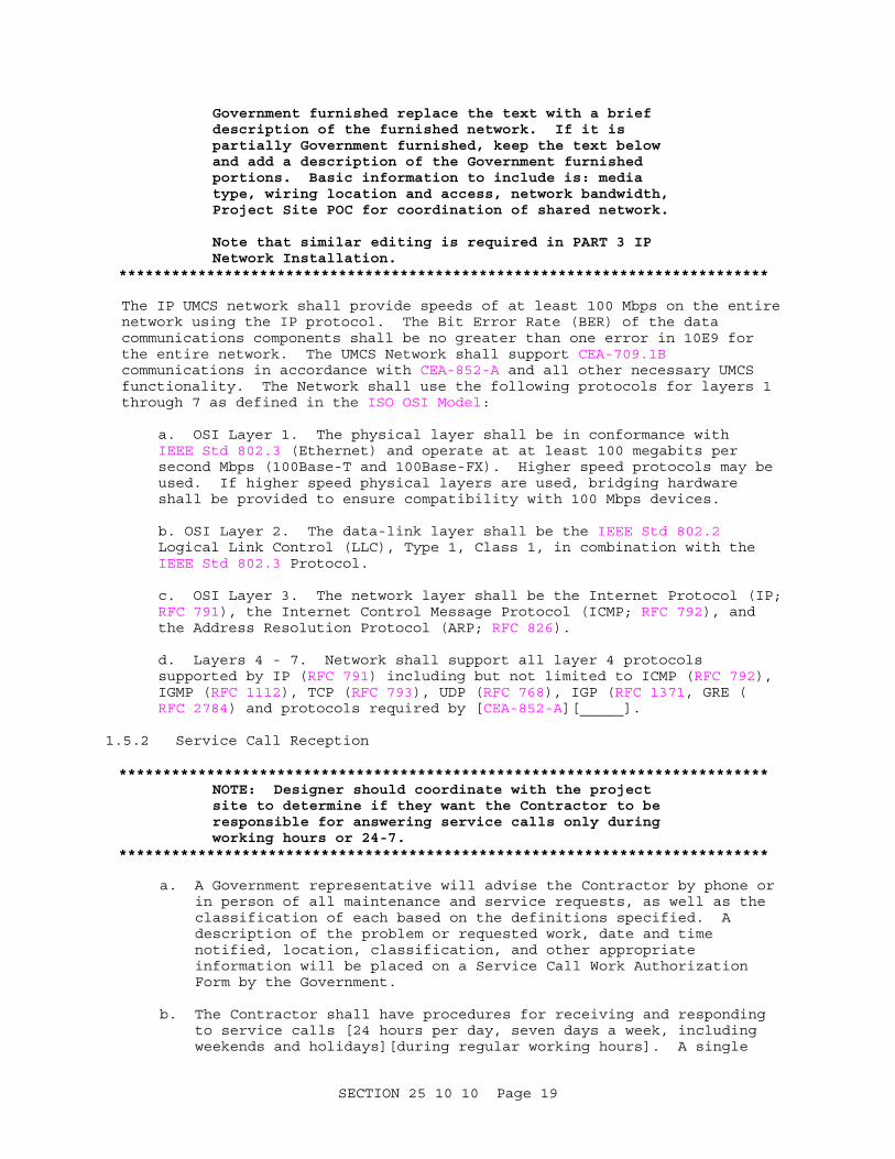
The IP UMCS network shall provide speeds of at least 100 Mbps on the entire network using the IP protocol. The Bit Error Rate (BER) of the data communications components shall be no greater than one error in 10E9 for the entire network. The UMCS Network shall support CEA-709.1B communications in accordance with CEA-852-A and all other necessary UMCS functionality. The Network shall use the following protocols for layers 1 through 7 as defined in the ISO OSI Model:
a. OSI Layer 1. The physical layer shall be in conformance with IEEE Std 802.3 (Ethernet) and operate at at least 100 megabits per second Mbps (100Base-T and 100Base-FX). Higher speed protocols may be used. If higher speed physical layers are used, bridging hardware shall be provided to ensure compatibility with 100 Mbps devices.
b. OSI Layer 2. The data-link layer shall be the IEEE Std 802.2 Logical Link Control (LLC), Type 1, Class 1, in combination with the IEEE Std 802.3 Protocol.
c. OSI Layer 3. The network layer shall be the Internet Protocol (IP; RFC 791), the Internet Control Message Protocol (ICMP; RFC 792), and the Address Resolution Protocol (ARP; RFC 826).
d. Layers 4 - 7. Network shall support all layer 4 protocols supported by IP (RFC 791) including but not limited to ICMP (RFC 792), IGMP (RFC 1112), TCP (RFC 793), UDP (RFC 768), IGP (RFC 1371, GRE (RFC 2784) and protocols required by [CEA-852-A][_____].
1.5.2 Service Call Reception
**************************************************************************NOTE: Designer should coordinate with the project site to determine if they want the Contractor to be responsible for answering service calls only during working hours or 24-7.
**************************************************************************
a. A Government representative will advise the Contractor by phone or in person of all maintenance and service requests, as well as the classification of each based on the definitions specified. A description of the problem or requested work, date and time notified, location, classification, and other appropriate information will be placed on a Service Call Work Authorization Form by the Government.
b. The Contractor shall have procedures for receiving and responding to service calls [24 hours per day, seven days a week, including weekends and holidays][during regular working hours]. A single
SECTION 25 10 10 Page 19

telephone number shall be provided for receipt of service calls during regular working hours. Service calls shall be considered received by the Contractor at the time and date the telephone call is placed by the authorized Government representative.
c. Separately record each service call request, as received on the Service Call Work Authorization form and shall complete the Service Call Work Authorization form for each service call. The completed form shall include the serial number identifying the component involved, its location, date and time the call was received, nature of trouble, names of the service personnel assigned to the task, instructions describing what has to be done, the amount and nature of the materials to be used, the time and date work started, and the time and date of completion.
d. Respond to each service call request within [two][_____] working hours. The status of any item of work must be provided within [four][_____] hours of the inquiry during regular working hours, and within [16][_____] hours after regular working hours or as needed to meet the Equipment Repair requirements as specified.
1.5.3 System Modifications
Make recommendations for system modification in writing to the Government. No system modifications shall be made without prior approval of the Government. Any modifications made to the system shall be incorporated into the Operations and Maintenance Instructions, and other documentation affected. Make available to the Government software updates for all software furnished under this specification during the life of this contract. There shall be at least one scheduled update near the end of the contract period, at which time the Contractor shall make available the latest released version of all software provided under this specification, and shall install and validate it upon approval by the Government.
1.5.4 UMCS Contractor Design Drawings
**************************************************************************NOTE: Designer must decide whether to require a specific drawing size (approx. 11x17 or 22x34) or to leave it up to the Contractor.
**************************************************************************
Revise and update the Contract Drawings to include details of the system design. Drawings shall be on [ISO A1 841 by 594 mm 34 by 22 inches][or][A3 420 by 297 mm 17 by 11 inches] sheets. Details to be shown on the Design Drawing include:
a. Details on logical structure of the network. This includes logical location of all network hardware.
b. Manufacturer and model number for each piece of computer and network hardware.
c. Physical location for each piece of network or computer hardware.
1.5.5 As-Built Drawings
**************************************************************************NOTE: The Points Schedule is a submittal from
SECTION 25 10 10 Page 20
Section 23 09 23 contracts and is a contract drawing for this Section. The Contractor updates the Points Schedule and submits it as an as-built.
**************************************************************************
Prepare draft as-built drawings consisting of Points Schedule drawings for the entire UMCS and an updated Design Drawing including details of the actual installed system as it is at the conclusion of Start-Up and Start-Up Testing. In addition to the details shown in the design drawings, the as-built drawing shall include:
a. IP address(es) as applicable for each piece of network hardware.
b. IP address for each computer server, workstation and networked printer.
c. Network identifier (name) for each printer, computer server and computer workstation.
d. CEA-709.1B address (domain, subnet, node address) for each CEA-709.1B TP/FT-10 to IP Router.
Prepare Draft As-Built Drawings upon the completion of Start-Up and Start-Up Testing and Final As-Built Drawings upon completion of PVT Phase II.
1.6 PROJECT/SITE CONDITIONS
Provide components which meet the following requirements:
a. Portions of the data communications equipment system installed in unconditioned spaces shall operate properly in an environment with ambient temperatures between -7 and +66 degreesC +20 and 150 degrees F and ambient relative humidity between 20% and 95% noncondensing.
b. Components shall accept 100 to 125 volts AC (Vac), 60 Hz, single phase, three wire with a three-pronged, dedicated circuit outlet or be provided with a transformer to meet the component's power requirements.
c. The equipment shall meet the requirements of NFPA 70, UL 60950, NFPA 262, FCC EMC, and 47 CFR 15.
1.7 PROJECT SEQUENCING
TABLE I: PROJECT SEQUENCING specifies the sequencing of submittals as specified in paragraph SUBMITTALS (denoted by an 'S' in the 'TYPE' column) and activities as specified in PART 3: EXECUTION (denoted by an 'E' in the 'TYPE' column).
a. Sequencing for submittals: The sequencing specified for submittals is the deadline by which the submittal must be initially submitted to the Government. Following submission there will be a Government review period as specified in Section 01 33 00 SUBMITTAL PROCEDURES. If the submittal is not accepted by the Government, revise the submittal and resubmit it to the Government within [14][_____] days of notification that the submittal has been rejected. Upon re-submittal there will be an additional Government review period. If the submittal is not accepted, the process repeats until the submittal is accepted by the Government.
SECTION 25 10 10 Page 21

b. Sequencing for Activities: The sequencing specified for activities indicates the earliest the activity may begin.
c. Abbreviations: In TABLE I the abbreviation AAO is used for 'after approval of' and 'ACO' is used for 'after completion of'.
TABLE I. PROJECT SEQUENCING
SEQUENCING (START OF ACTIVITY orITEM # TYPE DESCRIPTION DEADLINE FOR SUBMITTAL)------ ---- ------------------------------ --------------------------
1 S Factory Test Procedures 2 Perform Factory Test AAO #1 3 S Factory Test Report [_____] days ACO #2 4 S Existing Conditions Report [_____] days AAO #3 5 S Design Drawings [_____] days AAO #3 6 S Product Data Sheets [_____] days AAO #3 7 S Network Bandwidth Calculations [_____] days AAO #3 8 S Pre-construction QC Checklist [_____] days AAO #3 9 E Install UMCS AAO #4 thru #8 10 E Start-Up and Start-Up Testing ACO #9 11 S Post-Construction QC Checklist [_____] days ACO #10 12 S Computer Software [_____] days ACO #10 13 S Start-Up and Start-Up [_____] days ACO #10 Testing Report 14 S Draft As-Built Drawings [_____] days ACO #10 15 S PVT Phase I Procedures [_____] days before sched. start of #16 and AAO #13 16 E PVT Phase I AAO #15 and #14 17 S PVT Phase I Report [_____] days ACO #16 18 S Preventive Maintenance AAO #13 Work Plan 19 S O&M Instructions AAO #13 20 S Basic Operator Training AAO #13 and [_____] days Documentation before scheduled start of #21 21 E Basic Operator Training AAO #18, #19 and #20 (PVT Phase II) 22 S PVT Phase II Report [_____] days ACO #21 23 S Final As-Built Drawings [_____] days AAO #22 24 S Advanced Operator Training [_____] days before sched. Documentation start of #25 and AAO #20 25 E Advanced Operator Training ACO #21, [_____] days AAO #24, and no later than [60] days ACO #21 26 S Operator Refresher Training [_____] days before #27 and Documentation AAO #20 and #24 27 E Operator Refresher Training between [_____] and [_____] days ACO #21 and AAO #26 28 S Closeout QC Checklist ACO #25
1.8 WARRANTY
Provide a [1 year][_____] unconditional warranty on service call work. The
SECTION 25 10 10 Page 22

warranty shall include labor and material necessary to restore the equipment involved in the initial service call to a fully operable condition. In the event that Contractor service call work causes damage to additional equipment, the Contractor will be liable for labor and material to restore the system to full operation. Contractor response to service call warranty work shall be the same as required by the initial service call.
1.9 MAINTENANCE AND SERVICE
**************************************************************************NOTE: The maintenance and service to be provided by the Contractor for the duration of the IDIQ or maintenance contract is specified in this paragraph. The Maintenance and Service may need to be a separate bid item funded by O&M funds. If the UMCS networking equipment and supporting infrastructure is Government furnished equipment (see IP Network Installation paragraph in PART 3), it may be desirable to limit maintenance and service to Contractor supplied items.
Requirements should be coordinated with "WARRANTY MANAGEMENT" in Section 01 78 00 CLOSEOUT SUBMITTALS
**************************************************************************
1.9.1 Preventive Maintenance Requirements
Perform maintenance procedures as described below, or more often if required by the equipment manufacturer.
1.9.1.1 Preventive Maintenance Work Plan
**************************************************************************NOTE: Designer will delete if not required by the user.
**************************************************************************
Prepare a Preventive Maintenance Work Plan to schedule all required preventive maintenance. Government approval of the Work Plan shall be obtained as specified in paragraph PROJECT SEQUENCING. Strictly adhere to the approved work plan to facilitate Government verification of work. [If the Contractor finds it necessary to reschedule maintenance, a written request shall be made to the Government detailing the reasons for the proposed change at least five days prior to the originally scheduled date. Scheduled dates shall be changed only with the prior written approval of the Government.]
1.9.1.2 Semiannual Maintenance
Perform the following Semiannual Maintenance as specified:
a. Perform data backups on all Server Hardware.
b. Run system diagnostics and correct diagnosed problems.
c. Perform fan checks and filter changes for UMCS hardware.
d. Perform all necessary adjustments on printers.
SECTION 25 10 10 Page 23
e. Resolve all outstanding problems.
f. Install new ribbons, ink cartridges and toner cartridges into printers, and ensure that there is at least one spare ribbon or cartridge located at each printer.
1.9.1.3 Maintenance Procedures
**************************************************************************NOTE: Select whether notice must be given for maintenance that will result in downtime (off-line) or for any maintenance that MAY result in downtime. A selection of 'will' is recommended unless the project site requests otherwise.
Select appropriate down-times and notice times.**************************************************************************
a. Maintenance Coordination: Any scheduled maintenance event that [will][may] result in component downtime shall be coordinated with the Government as follows. Time periods shall be measured as actual elapsed time from beginning of equipment off-line period, including working and non-working hours.
(1) For non-redundant computer server hardware, provide [14][_____] days notice, components shall be off-line for no more than [8][_____] hours.
(2) For non-redundant computer workstation hardware, provide [7][_____] days notice, components shall be off-line for no more than [8][_____] hours.
(3) for redundant computer server hardware, provide [7][_____] days notice, components shall be off-line for no more than [36][_____] hours.
(4) For redundant computer workstation hardware, provide [4][_____] days notice, components shall be off-line for no more than [48][_____] hours.
(5) For active (powered) network hardware, provide [14][_____] days notice, components shall be off-line for no more than [6][_____] hours.
(6) For cabling and other passive network hardware, provide [21][_____] days notice, components shall be off-line for no more than [12][_____] hours.
b. Software/Firmware: Software/firmware maintenance shall include operating systems, application programs, and files required for the proper operation of the UMCS regardless of storage medium. User (project site) developed software is not covered by this contract, except that the UMCS software/firmware shall be maintained to allow user creation, modification, deletion, and proper execution of such user-developed software as specified. Perform diagnostics and corrective reprogramming as required to maintain total UMCS operations as specified. Back up software before performing any computer hardware and software maintenance. Do not modify any parameters without
SECTION 25 10 10 Page 24

approval from the Government. Any approved changes and additions shall be properly documented, and the appropriate manuals shall be updated.
**************************************************************************NOTE: Network maintenance should only be required for Contractor furnished networks. If using a Government furnished network delete the requirement.
**************************************************************************
[c. Network: Network maintenance shall include testing transmission media and equipment to verify signal levels, system data rates, errors and overall system performance.]
1.9.2 Operation and Maintenance (O&M) Instructions
The UMCS Operation and Maintenance Instructions shall include:
a. Procedures for the UMCS system start-up, operation and shut-down.
b. Final As-Built drawings.
c. Routine maintenance checklist. The routine maintenance checklist shall be arranged in a columnar format. The first column shall list all installed devices, the second column shall state the maintenance activity or state no maintenance required, the third column shall state the frequency of the maintenance activity, and the fourth column for additional comments or reference.
d. Qualified service organization list.
e. Start-Up and Start-Up Testing Report.
f. Performance Verification Test (PVT) Procedures and Reports.
PART 2 PRODUCTS
2.1 EQUIPMENT REQUIREMENTS
2.1.1 Product Sourcing
Contractor supplied units of the same type of equipment shall be products of a single manufacturer. Each major component of equipment shall have the manufacturer's name and the model and serial number in a conspicuous place. Materials and equipment shall be new standard unmodified products of a manufacturer regularly engaged in the manufacturing of such products. Computing devices, as defined in 47 CFR 15, supplied as part of the UMCS shall be certified to comply with the requirements of Class B computing devices.
2.1.2 Nameplates
Laminated plastic nameplates shall be provided for all network hardware, each server and workstation. Each nameplate shall identify the function, network address and identifier of the device. Laminated plastic shall be 3 mm 0.125 inch thick, white with black center core. Nameplates shall be a minimum of 25 by 75 mm 1 by 3 inch with minimum 6 mm 0.25 inch high engraved block lettering. Nameplates shall be attached to the device in conspicuous location.
SECTION 25 10 10 Page 25
2.1.3 Product Data Sheets
For each product specified in this contract, manufacturer catalog cuts and sheets which indicate conformance to product requirements shall be submitted as specified.
2.2 NETWORK HARDWARE
2.2.1 Building Point of Connection (BPOC) Hardware
**************************************************************************NOTE: FYI: BPOCs are the interface between Sections 25 10 10 and 23 09 23.
**************************************************************************
2.2.1.1 CEA-709.1B TP/FT-10 to IP Router
CEA-709.1B TP/FT-10 to IP Routers shall perform layer 3 routing of CEA-709.1B packets over an IP network in accordance with CEA-852-A. The router shall provide the appropriate connection to the IP network and connections to the CEA-709.3 TP/FT-10 network. CEA-709.1B TP/FT-10 to IP Routers shall support the Dynamic Host Configuration Protocol (DHCP; RFC 2131 for IP configuration the use of an CEA-852-A Configuration Server (for CEA-852-A configuration), but shall not rely on these services for configuration. CEA-709.1B TP/FT-10 to IP Routers shall be capable of manual configuration.
2.2.1.2 CEA-709.1B Gateway
**************************************************************************NOTE: FYI: Gateways will be used only for integration of legacy systems. Gateways should not be used to allow a new, non-CEA-709.1B system to be installed.
**************************************************************************
Gateways shall have the appropriate connection on the building-side (non-CEA-709.1B side) to interface to the building DDC system, and shall meet the following requirements:
a. It shall be capable of being installed, configured and programmed for the designated application and through the use of instructions in the manual supplied by the Contractor.
b. All software required for gateway configuration shall be provided.
c. It shall provide bi-directional protocol translation between the building level control protocol and CEA-709.1B.
d. It shall allow bi-directional mapping between Standard Network Variable Types (SNVTs) according to the LonMark SNVT List on the CEA-709.1B side and points on the building control network.
**************************************************************************NOTE: FYI: The following item allows both translation from Legacy to IP and translation from Legacy to TP/FT-10 followed by TP/FT-10 to IP conversion.
**************************************************************************
SECTION 25 10 10 Page 26
d. It shall communicate on the CEA-709.1B over an IP network in accordance with CEA-852-A. Contractor may provide a CEA-709.1B TP/FT-10 to IP Router co-located with the protocol translator to meet this requirement.
e. It shall allow binding of its standard network variables (SNVTs).
f. For the CEA-709.1B network, it shall be capable of transmitting data using the "min, max, and delta" (throttling and heartbeat) methodology.
g. It shall provide the ability to label SNVTs that are mapped to or from third party devices.
**************************************************************************NOTE: Indicate if additional capability may be required. Note that since the Legacy system should not change this requirement shouldn't be needed, and when used will normally be intended to cover the case of 'forgotten' points (when the mapping requirements from the legacy system have not been fully/properly identified).
**************************************************************************
h. It shall provide capacity for mapping all required points as shown[ plus an additional [50%][_____]] from the legacy side as SNVTs on the CEA-709.1B side and vice-versa.
i. It shall be capable of supporting polled and synchronous modifiers for network variables.
j. It shall supply a LonMark external interface file (XIF) as defined in the LonMark XIF Guide for use with LNS tools and utilities.
k. It shall have a "service pin" which, when pressed, will cause the Gateway to broadcast its 48-bit NodeID and ProgramID over the network.
l. It shall provide a configurable self-documenting string.
m. It shall retain its configuration after a power loss of an indefinite time, and shall automatically return to its pre-power loss state once power is restored.
2.2.2 IP Network Hardware
2.2.2.1 Wire and Cables
**************************************************************************NOTE: Indicate type of fiber and type of connectors to be used, or if it's left to the Contractor to decide. If using any of the project sites IT infrastructure, coordinate with the DOIM (IT group) to determine which type of fiber to specify. Use of Multimode fiber for interior work is recommended. Use of SC type connectors is recommended.
**************************************************************************
a. Interior LAN Copper Cable: Interior Copper LAN cable shall meet or
SECTION 25 10 10 Page 27

exceed all requirements of Category 5 cable as specified in TIA/EIA-568-B.1. Terminations, patch panels, and other hardware shall meet or exceed Category 5 specifications and shall be as specified in SECTION 27 10 00 BUILDING TELECOMMUNICATIONS CABLING SYSTEM. Cabling products shall be tested and certified for use at data speeds up to at least 100 Mbps. Other types of media commonly used within IEEE Std 802.3 LANs (e.g., 10Base-T and 10Base-2) shall be used only in cases to interconnect with existing media. Short lengths of media and transceivers may be used in these applications. Provide separately orderable media, taps and connectors.
b. Interior Fiber Optic Cable: Interior Fiber Optic Cable shall be [Multimode][Singlemode][Multimode or Singlemode] fiber, [62.5/125][10/125][62.5/125 micron for multimode or 10/125 micron for singlemode] with [SC][ST][SC or ST] connectors as specified in TIA/EIA-568-B.1. Terminations, patch panels, and other hardware shall be compatible with the specified fiber and shall be as specified in SECTION 27 10 00 BUILDING TELECOMMUNICATIONS CABLING SYSTEM. The data communications equipment shall use the [850-nm range of multimode][1310-nm range of singlemode][850-nm range of multimode or 1310-nm range of singlemode] fiber-optic cable. Fiber-optic cable shall be suitable for use with the 100Base-FX standard as defined in IEEE Std 802.3.
c. Exterior Fiber Optic Cable: Exterior Fiber Optic Cable shall be [Multimode][Singlemode][Multimode or Singlemode] Fiber, [62.5/125][10/125][62.5/125 micron for multimode or 10/125 micron for singlemode] micron with [SC][ST][SC or ST] connectors as specified in TIA/EIA-568-B.1. Terminations, patch panels, and other hardware shall be compatible with the specified fiber and shall be as specified in Section 40 95 33.23 20 FIBER OPTIC (FO) OUTSIDE PLANT (OSP) MEDIA. The data communications equipment shall use the [850-nm range of multimode][1310-nm range of singlemode][850-nm range of multimode or 1310-nm range of singlemode] fiber-optic cable. Fiber-optic cable shall be suitable for use with the 100Base-FX standard as defined in IEEE Std 802.3.
2.2.2.2 Fiber Optic Patch Panel.
Fiber Optic Patch Panels shall be wall or rack mountable and designed to provide termination facilities for up to 24 fibers. Unit shall also have capability to be equipped with spliced trays, six packs (for adapters), and blank panels for easy termination of the fiber bundles and tube cables. Fiber-optic terminating equipment shall provide for mounting of ST or SC connectors on an optical patch panel. Provide fiber-cable management and cable-routing hardware to assure conformance to minimum fiber and cable bend radii. Connectors on the patch panel shall be ST or SC feed through. Provide access to both sides of the panel. The patch panel for the connectors shall be mounted to facilitate rearrangement and identification. Each apparatus shall have cabling and connection instructions associated with it.
2.2.2.3 Fiber Optic Media Converter
Fiber Optic media converter shall provide media conversion between layer 1 copper and fiber media to support data rates equal to the greater of the physical layer or 100 Mbps as specified in IEEE Std 802.3.
SECTION 25 10 10 Page 28

2.2.2.4 Ethernet Switch
Switches shall be IEEE Std 802.3 bridges which shall function as the center of a distributed-star architecture and shall be "learning" bridges with spanning tree algorithms in accordance with IEEE Std 802.1D. The switch shall support the connected media types and shall have a minimum of 150% the required ports and no fewer than 4 ports. One port shall be switch selectable as an uplink port.
2.2.2.5 IP Router
Provide IP router network equipment. The routers shall be fully configurable for protocol types, security, and routing selection of sub-networks. The router shall meet all requirements of RFC 1812.
2.3 COMPUTER HARDWARE
2.3.1 Server Hardware
**************************************************************************NOTE: Coordinate with the Project Sites DOIM (IT group) and include the sites 'standard' server redundancy requirements.
**************************************************************************
Computer Server Hardware (server) shall be a standard unmodified digital computer of modular design currently being manufactured. The modular components of the server shall be products of a single manufacturer which advertises service in all 48 contiguous states. Server hardware shall meet the following minimum requirements.
a. Processor speed: Minimum 250% of the stated requirements of the software to be installed on the server.
b. Random Access Memory (RAM): Minimum 250% of the stated requirements of the software to be installed on the server.
c. Communications ports: One serial port, one enhanced parallel port and one USB port in addition to any ports required for the keyboard and mouse.
d. Hard Drives and Controller: Controller and Drives shall provide at least [120GB] [_____] usable disk space with an average seek time of 7 milliseconds or less using hardware RAID (Redundant Array of Inexpensive Disks) at levels 1 or 5 (RAID-1 or RAID-5).
e. CD/DVD-RW Drive: Combo CD-RW with 32x read, 24x write and 16x rewrite and DVD-RW with 12x read; 4x re-write; 2x write.
f. Floppy Disk Drive and controller: High density (1.44MB) disk drive 90 mm 3.5 inch diameter size.
g. Video output card: Support at least 16 bit color at a minimum resolution of 1280 by 1024 at a minimum refresh rate of 70 Hz.
h. Network Interface Card (NIC): Integrated [100Base-T Ethernet NIC with an RJ45 connector.][100Base-FX Ethernet NIC with an [SC][ST] connector.]
SECTION 25 10 10 Page 29

i. Monitor: Sized as shown but no less than 432 mm 17 inches with a minimum resolution of 1024 by 768 pixels, non-interlaced, a maximum dot pitch of 0.28 millimeters, and a minimum refresh rate of 70Hz.
j. Keyboard: 101 key keyboard having a minimum 64 character standard ASCII character set based on ANSI INCITS 154.
k. Mouse: 2-button mouse with a minimum resolution of 400 dots per inch.
l. Hot-swappable redundant power supplies.
2.3.2 Workstation Hardware (Desktop and Laptop)
Computer Workstation Hardware (workstation) shall be a standard unmodified digital desktop computer of modular design or a laptop as shown. The modular components of the desktop, or the laptop, shall be products of a single manufacturer which advertises service in all 48 contiguous states. Workstations shall meet the following minimum requirements.
a. Processor speed: 150% the stated requirements of the software to be installed on the workstation.
b. Random Access Memory (RAM): 150% the stated requirements of the software to be installed on the workstation.
c. Communications ports:
(1) Desktop: One serial port, one enhanced parallel port and two USB ports in addition to any ports required for the keyboard and mouse.
(2) Laptop: One serial port, one enhanced parallel port, one USB port, one PCMCIA card slot, and one additional USB or PS/2 port for a mouse.
d. Hard Drive and controller:
(1) Desktop: [60GB] [___] formatted disk space with an average seek time of 7 milliseconds or less.
(2) Laptop: [40GB] [___] formatted disk space with an average seek time of 10 milliseconds or less.
e. CD-RW Drive: 24x read; 12x re-write; 24x write. For laptops the CD-RW drive [shall be a fixed drive][shall be a fixed or modular-bay drive][shall be a fixed, modular-bay or external drive].
f. Floppy Disk Drive and controller: High density (1.44MB) disk drive 90mm (3.5inch) diameter size. For laptop workstations the floppy disk drive shall be a [fixed drive][fixed or modular-bay drive][fixed, modular-bay or external drive].
g. Video output card:
(1) Desktop: Support at least 32 bit color at a minimum resolution of 1280 by 1024 at a minimum refresh rate of 70 Hz.
(2) Laptop: Support at least 16 bit color at a minimum resolution
SECTION 25 10 10 Page 30

of 1024 by 768 at a minimum refresh rate of 60 Hz.
h. Network Interface Card (NIC):
(1) Desktop: Integrated [100Base-TX Ethernet NIC with an RJ45 connector.][100Base-FX Ethernet NIC with an [SC][ST] connector]
(2) Laptop: Integrated or PCMCIA 100Base-TX Ethernet NIC with an RJ45 connector.
i. Monitor:
(1) Desktop: Monitor sized as shown but no less than 482 mm 19 inches with a maximum supported resolution of no less of 1280 by 1024 pixels, non-interlaced, and a maximum dot pitch of 0.28 millimeters.
(2) Laptop: LCD Screen sized as shown but no less than 305 mm 12 inches with a maximum supported resolution of no less than 1024 by 768 pixels
j. Keyboard:
(1) Desktop: 101 key keyboard having a minimum 64 character standard ASCII character set based on ANSI INCITS 154.
(2) Laptop: Standard laptop keyboard.
k. Mouse:
(1) Desktop: 2-button mouse with a minimum resolution of 400 dots per inch.
(2) Laptop: Integrated touch-pad.
2.3.3 Printers
Printers shall be local or network printers as shown. Local printers shall have a parallel or USB interface. Network printers shall have a 100Base-T interface with an RJ45 connection and shall have a firmware print spooler compatible with the Operating System print spooler.
2.3.3.1 Alarm Printer
The dot matrix alarm printers shall have a minimum 96 character standard ASCII character set based on ANSI INCITS 154 and with graphics capability. The printers shall have adjustable sprockets for paper width up to 279 mm 11 inches, print at least 80 columns per line and have a minimum speed of 200 characters per second. Character spacing shall be selectable at 10, 12 or 17 characters per inch. The printers shall use sprocket-fed fanfold paper. The units shall have programmable control of top-of-form.[ Printers shall include floor stands with paper racks.]
2.3.3.2 Laser Printer
Laser printers shall meet the following minimum requirements:
a. Resolution: 600 by 600 dots per inch.
SECTION 25 10 10 Page 31
b. Printing Time: 10 pages per minute.
c. Data Buffer Size: 10 Megabytes.
d. Media Size: 216 by 279 mm 8.5 by 11 inches as shown.
e. Paper Cassette: 250 sheet capacity.
2.3.3.3 Color Printer
The color printer shall use ink jet technology, shall be a full-color printer, and shall meet the following minimum requirements:
a. Resolution: 600 by 600 dots per inch.
b. Printing Time: 2 pages per minute.
c. Data Buffer Size: 16 Megabytes.
d. Colors: Printer shall have a separate replaceable black ink cartridge or print head.
e. Media Type: Paper and transparency film.
f. Media Size: 216 by 279 mm 8.5 by 11 inches and as shown.
g. Paper Cassette: 250 sheet capacity.
2.4 COMPUTER SOFTWARE
2.4.1 Operating System (OS)
The operating system (OS) shall fully support all installed software and peripherals and shall be able to obtain screen capture of the monitor display being viewed.
2.4.2 Office Automation Software
Office Automation Software shall consist of the [e-mail, ]spreadsheet and word processing portions of the project site's standard office automation software.
2.4.3 Virus Protection Software
Virus Protection Software shall consist of the project site's standard virus protection software complete with a virus definition update subscription.
2.4.4 CEA-852-A Configuration Server
The CEA-852-A configuration server shall meet the requirements of CEA-852-A.
2.4.5 CEA-709.1B Network Configuration Tool
The network configuration tool shall meet the following minimum requirements:
a. It shall solely use LonWorks Network Services (LNS) for all network configuration and management of CEA-709.1B devices.
SECTION 25 10 10 Page 32

b. It shall be capable of executing LNS plug-ins.
c. It shall be capable of performing network database reconstruction of an CEA-709.1B control network, such that if connected to an existing CEA-709.1B network it has the ability to query the network and create an LNS database for that network and an associated network drawing.
d. It shall allow configuration of the network while off-line such that an operator may set up changes to the network while disconnected from the network, and then execute all of them once connected.
e. It shall have a graphics-based user interface, and be able to display and print a graphical representation of the control network.
f. It shall be capable of generating and printing the following reports:
(1) Table containing domain/subnet/node address and node identifier for the entire network or any subset thereof, selected by the user.
(2) Table containing Standard Network Variable (SNVT) input and output details for any CEA-709.1B device on the network.
(3) Table containing Standard and User-Defined Configuration Properties (SCPTs and UCPTs) for any CEA-709.1B device on the network.
g. It shall be capable of merging two existing standard LNS databases into a single standard LNS database.
2.4.6 Monitoring and Control (M&C) Software
**************************************************************************NOTE: Designer should choose the minimum number of points and clients the M&C software is required to accommodate based on the project site's master plan. The initial number of points to be accommodated should be chosen such that it is sufficient to cover all current and known future projects. The total system expansion requirement should be based on potential/anticipated future projects.
{Points means "points that the M&C software can read/write on the network'. In general, points will be SNVTs, but they may include configuration properties and/or variables (points) from a legacy system (via a protocol driver)}.
Web based clients are not specifically addressed here. The Contractor may provide web-based or non-web-based clients as needed to meet the M&C software functional requirements. If web based clients are specifically required or are not allowed, edit the M&C Software requirements accordingly See the UFC for more information.
**************************************************************************
SECTION 25 10 10 Page 33
**************************************************************************NOTE: FYI: The following paragraphs/pages (the M&C software requirements) specify functionality that is required for the M&C Software but that may not be achievable due to lack of data/support at the building level. In order to meet future needs these requirements should be kept. It is expected that they are usually part of the 'standard' capabilities of this type of software.
**************************************************************************
The monitoring and control (M&C) software shall be an LNS-compatible client-server software package. The software shall accommodate [_____] points and shall be expandable via licensing upgrade to accommodate up to [50,000][_____] points without requiring additional software installation. The server software shall support clients as specified and shown and shall be expandable via licensing upgrade to support no less than [50][_____] total clients and no less than [20][_____] clients simultaneously without requiring additional server software installation.
2.4.6.1 Passwords
**************************************************************************NOTE: Designer must choose if password management for M&C software is performeda) by the OSorb) by the M&C software itselforc) if the decision is left to the Contractor.
**************************************************************************
The M&C software shall provide user-based access to M&C functionality. The M&C Software shall [obtain user information from the OS][or][manage M&C user information] and shall recognize at least [100][_____] separate users and have at least 4 levels of user permissions. User permission levels (from most restrictive to most permissive) shall include:
a. Permission Level 1: View System Graphic Displays.
b. Permission Level 2: Permission Level 1 plus acknowledge alarms and set up (configure) trends and reports.
c. Permission Level 3: Permission Level 2 plus override SNVTs and set up (configure) alarms, schedules and demand limiting.
d. Permission Level 4: Permission Level 3 plus create and modify System Graphic Displays and create custom programs.
Passwords shall not be displayed. The system shall maintain a disk file logging all activity of the system. If the file format is not plain ASCII text, provide a means to export or convert the file to plain ASCII text. This file shall maintain, as a minimum, a record of all operators logged onto the system, alarm acknowledgments, commands issued and all database modifications. Passwords shall not be logged. The activity log shall be maintained at the server hardware. The system shall automatically provide a mechanism for archiving the log files for long term record storage.
SECTION 25 10 10 Page 34
2.4.6.2 Protocol Drivers
**************************************************************************NOTE: FYI: one of the integration methods for legacy systems is to use a protocol driver (a 'software gateway') in the M&C software to integrate the legacy system.
**************************************************************************
The M&C Software may include drivers to other (non-CEA-709.1B) protocols. The protocol driver shall allow all M&C Software functions to write values to and read values from points on the legacy system. The M&C software shall support reading points from the legacy system and writing these values to SNVTs on the CEA-709.1B network, and reading SNVTs from the CEA-709.1B network and writing these values to points on the legacy network. Use of the driver to integrate additional legacy systems shall not require programming but may require configuration.
2.4.6.3 System Graphic Displays
The monitoring and control (M&C) software shall include graphical displays through which an operator can perform real-time access and manipulation of the M&C functions as specified and shown. The graphical displays shall consist of building-level system (air handler units, VAV boxes, chillers, boilers etc) graphic displays, alarm displays, scheduling displays, trending displays, and demand limiting displays. Data associated with an active display shall be updated at least once every 5 seconds.
a. Navigation Scheme: System graphic displays of building-level systems and points shall be hierarchical displays using a building-to-equipment point-and-click navigation scheme. Each display shall show the building name and number. Each display shall show system wide data such as outside air temperature and humidity in the case of an HVAC system application.
(1) Each Building or Building Sub-Area display shall show the building foot print and basic floor plan, and shall clearly show and distinguish between the individual zones and the equipment serving each zone and space. The building display shall also show all space sensor and status readings, as applicable, for the individual zones such as space temperature, humidity, occupancy status, etc. The building display shall show the locations of individual pieces of monitored and controlled equipment.
(2) Each equipment display shall show a [one-line diagram control schematic][3-dimensional] representation of the individual pieces of equipment using the symbols and M&C point data types as specified. Different colors and textures shall be used to indicate various components and real time data. Color and texture meanings shall be consistent across all displays.
(3) Each display shall clearly distinguish between the following point data types and information:
(a) Real-time data.
(b) User-entered data.
(c) Overridden or operator-disabled points.
SECTION 25 10 10 Page 35
(d) Devices in alarm (unacknowledged).
(e) Out-of-range, bad, or missing data.
b. Navigation Commands: The system graphic displays shall support English language operator commands via point-and-click mouse or keyboard entry for defining and selecting points, parameters, graphics, report generation, and all other functions associated with operation. The operator commands shall be usable from any operator workstation with individual operator passwords as specified.
(1) Command Input: Operator's commands shall be full words and acronyms selected to allow operators to use the system without extensive training or any data processing backgrounds. The system shall prompt the operator in full words and acronyms for all required information, identifying acceptable command formats. The operator's response shall be a point-and-click selection, word, phrase, or acronym including parameters where required.
(2) Command Input Errors: The system shall supervise operator inputs to ensure they are correct for proper execution. Operator input assistance shall be provided whenever a command cannot be executed because of operator input errors. The system shall explain to the operator why the command cannot be executed. Conditions for which operator error assist messages shall be generated include:
(a) The command used is incorrect or incomplete.
(b) The operator is restricted from using that command.
(c) The command addresses an out-of-range or bad data point.
(d) The command addresses a point that does not exist.
(e) The command would violate constraints.
(3) Special Functions: The system shall provide the following point-and-click mouse functions, in addition to all other commands specified:
(a) HELP: shall produce an indexed or menu-driven display of all commands available to the operator. The HELP command, followed by a specific command shall produce a context sensitive listing with a short explanation of the purpose, use, and system reaction to that command.
(b) DISPLAY DIAGRAM: shall display diagrams of specific utility systems or other systems as specified.
(c) DIAGRAM DEVELOPMENT: shall allow the user to develop diagrams of specific utility systems or other systems as specified.
(d) PRINT REPORT: Shall allow the operator to initiate printing of reports.`
(4) Operator's Commands: The operator's commands shall provide
SECTION 25 10 10 Page 36
the means for entry of control and monitoring commands, and for retrieval of information. Processing of operator commands shall commence within 1 second of entry, with some form of acknowledgment provided at that time. The operator's commands shall perform tasks, including:
(a) Request a display of any SNVT or calculated point or any group of related SNVTs and calculated points
(b) Startup and shutdown selected systems or devices.
(c) Override any SNVT point to an operator selected value.
(d) Release the override of a SNVT.
(e) Modify time and event scheduling.
(f) Initiate reports.
(g) Generate and format reports.
(5) System Graphic Display Hierarchy: The system graphic display shall have a hierarchical structure with at least five levels:
(a) Unit: The unit that a point is associated with, such as an AHU.
(b) Building Sub-Area: A part of a building.
(c) Building: The building that a point is located in or near.
(d) Building Group: A group of buildings.
(e) Facility: Installation included in the UMCS.
c. Display Editor: The display editor shall enable the user to create, modify, and delete displays and graphic symbols. The primary use shall be for adding and modifying one-line diagrams, status displays, system summaries, and system directories, as new controllers, points, data, and other necessary changes are made. The basic functions shall include:
(1) Create and save displays and graphic symbols.
(2) Group and ungroup graphic symbols. The grouped symbol shall be manipulated as a single symbol.
(3) Modify a portion of a graphic symbol.
(4) Save graphic symbols as a library object.
(5) Rotate and mirror a graphic symbol.
(6) Delete a graphic symbol.
(7) Place a graphic symbol on a display.
(8) Cancel the display of a graphic symbol.
SECTION 25 10 10 Page 37

(9) Assign conditions which automatically initiate the display.
(10) Overlay alphanumerics and graphics.
(11) Save new, modified, or existing graphics as new graphics.
(12) Integrate real-time data with the display.
(13) Define the background color.
(14) Define the foreground color.
(15) Locate the symbols.
(16) Position and edit alphanumeric descriptors.
(17) Establish connecting lines.
(18) Establish sources of latest data and location of readouts.
(19) Display analog values as specified.
(20) Cursor control (up, down, right, left).
(21) Create and display alphanumeric displays.
(22) Assign graphics a depth such that when there are coincident graphics the one with the lower depth is displayed.
(23) Modify graphic properties based on SNVT values, calculated values or values obtained from a legacy system.
(24) Creating conditional displays such that different graphic symbols or text are displayed based on SNVT values, calculated values or values obtained from a legacy system.
(25) Symbols Library: The library of callable display symbols shall include: Pump, Motor, Two- and Three-way Valves, Flow Sensing Element, Point and Averaging Temperature Sensors, Pressure Sensor, Humidity Sensor, Single and Double Deck Air Handling Unit, Fan, Chiller, Boiler, Air Compressor, Chilled Water Piping, Steam Piping, Hot Water Piping, Ductwork, Unit Heater, Pressure Reducing Valve, Damper, Electric Meter, Limit Switch, Flow Switch, High- and Low- Point and Averaging Temperature Switches, High- and Low- Pressure Switches, Coil, Solenoid Valve, Filter, Condensing Unit, Cooling Tower, Variable Frequency Drive (VFD), Heat Exchanger, Current Sensing Relays. Symbols shall at a minimum conform to ASHRAE FUN SIASHRAE FUN IP where applicable.
2.4.6.4 Scheduling
**************************************************************************NOTE: FYI: The M&C software will be the primary method of scheduling. Building systems have 'backup' scheduling capability in the event of a loss of communication with the M&C Software Server.
**************************************************************************
The M&C software shall be capable of changing the value of any SNVT in the
SECTION 25 10 10 Page 38
LNS Database and any point available from a connected legacy system via the protocol driver to any legal value according to a schedule. A minimum of [200][_____] user-definable schedules shall be supported and the specified scheduling functions shall be operator accessible and adjustable via graphics display. The graphics display shall include the following fields and functions:
a. Current date and time. The OS and M&C software shall automatically make Daylight Savings Time adjustments. Daylight savings time adjustment shall be capable of being disabled by the operator.
b. Building name and number.
c. System identifier and name.
d. System group. Systems shall be capable of being grouped by the user to perform according to a common schedule.
e. Weekly schedules. Each system shall have a weekly schedule based on a seven day per week schedule with independent schedules for each day of the week including no less than 6 value changes per day.
f. Holiday and special event schedules. System scheduling shall support holiday and special event calendar schedules independent of the daily schedule. Special event schedules shall include one-time events and recurring events. Scheduling of one-time events shall include the beginning and ending dates and times of the event. Holiday and special event schedules shall have precedence over device weekly schedules.
2.4.6.5 Alarms
The M&C software shall be capable of generating alarms and handling network variable inputs of type SNVT_Alarm from the control network. M&C Software shall be capable of handling and managing no less than [10,000][_____] alarm points.
a. Alarm Data. Alarm data to be displayed and stored, as applicable and as specified, shall include:
(1) Identification of alarm including building, system (or sub-system), and device name.
(2) Date and time to the nearest second of occurrence.
(3) Alarm type:
(a) Unreliable: Indicates that the source device has failed due to the sensing device or alarm parameter being out-of-range or bad data.
(b) High Alarm.
(c) Low Alarm.
(4) Alarm set point and deadband(if analog).
(5) Engineering units.
(6) Current value or status of the alarm point.
SECTION 25 10 10 Page 39

(7) Alarm priority: There shall be two alarm priority levels; critical and informational. Critical alarms shall remain in alarm until acknowledged by an operator and the alarm condition no longer exists; informational alarms shall remain in alarm until the alarm condition no longer exists or until the alarm is acknowledged.
(8) Alarm Message: A unique message with a field of 60 characters shall be provided for each alarm. Assignment of messages to an alarm shall be an operator editable function.
(9) Alarm Secondary Message: Secondary messages shall be assignable by the operator for printing to provide further information, such as telephone lists or maintenance functions, and shall be editable by the operator. The system shall provide for 100 secondary messages, each with 25 lines of 60 characters each.
(10) Acknowledgement status of the alarm and, where acknowledged, the time and date of acknowledgement.
(11) User who acknowledged the alarm.
b. Alarm Notification and Routing: The M&C software shall be capable of performing alarm notification and routing functions. Upon receipt or generation of an alarm the M&C software shall immediately perform alarm notification and routing according to an assigned routing for that alarm. The M&C software shall support at least [500][_____] alarm routes; an alarm route shall be a unique combination of any of the following activities:
(1) Generate a pop-up up display on designated workstation monitors. The pop-up display shall include identification of the alarm, date and time of the alarm, alarm message, and current value/status of the alarm point. Alarms shall be capable of being acknowledged from the pop-up display by operators with sufficient permissions. Pop-up displays shall be displayed until acknowledged.
(2) Dial a numeric paging system and leaving a numeric message. The paging system number and numeric message shall be user configurable for each alarm route.
(3) Send an e-mail message via simple mail transfer protocol (SMTP; RFC 821). The e-mail shall contain a scripted message and all alarm data. The e-mail recipient and scripted message shall be user configurable for each alarm route.
(4) Print alarms to designated alarm printers. The printed message shall be the same as the pop-up message.
c. Alarm Display and Acknowledgement. The M&C software shall include an alarm display. A minimum of the most recent [100][_____] system alarms shall be available for display at each workstation as shown, along with all associated alarm data. Alarms shall be capable of being acknowledged from this display. Multiple alarms shall be capable of being acknowledged using a single command. Operator acknowledgment of one alarm shall not automatically be considered as acknowledgment of any other alarm nor shall it inhibit reporting of subsequent alarms.
SECTION 25 10 10 Page 40

d. Alarm Storage and Reports: The M&C software shall store each alarm and its associated alarm data to hard disk. The stored data shall be user-sortable and formatted for printing.
2.4.6.6 Trending
**************************************************************************NOTE: Designer should determine required number of points M&C software is capable of trending based on the project site's master plan.
**************************************************************************
The M&C software shall be capable of performing real-time trending on a minimum of [5,000][_____] points simultaneously with a minimum trending capacity of 100 points per second. The M&C software shall be capable of displaying and printing a graphical representation of each trend, and of multiple trended points on the same graph. The software shall be capable of saving trend logs to a file. If the file format is not plain ASCII text in a Comma-Separated-Value (CSV) format, provide a means to export or convert the file to plain ASCII text in a CSV format. Each trend shall be user-configurable for:
a. Point to trend.
b. Sampling interval with a minimum sampling interval no greater than 1 second, and a maximum sampling interval no less than 1 hour.
c. Start and Stop Time of Trend: Start and stop times shall be determined by one or more of the following methods:
(1) Start Time and Stop Time
(2) Start Time and Duration
(3) Start Time and number of samples
2.4.6.7 Electrical Power Demand Limiting
**************************************************************************NOTE: The System Scheduler (referenced below) is specified in Section 23 09 23 DIRECT DIGITAL CONTROL FOR HVAC AND OTHER LOCAL BUILDING SYSTEMS.
The critical alarm for actual demand exceeding the Electrical Demand Target (EDT) should be routed such that it is received as soon as possible.
Designer must decide if actual demand exceeding EDT causes the EDT to be reset to a higher value.
The billing structure should be obtained from the utility supplying electrical service in order to coordinate equipment demand limit priorities with the project site's Energy Manager. If real time pricing is a part of the billing structure it will also require coordination with the demand limiting program.
**************************************************************************
SECTION 25 10 10 Page 41
The UMCS shall be able to monitor and limit the electrical demand using a demand limiting program, subject to the availability of appropriate data and control hardware. The demand limiting program shall operate continuously and shall execute at the M&C Software Server. It shall obtain electrical demand from the installation electric utility meters a minimum of once per minute and predict the electrical peak demand [30][_____] minutes into the future. This predicted peak demand value shall be recalculated at a minimum of [one (1)][_____] minute intervals. The Electrical Demand Target (EDT) and predicted demand shall be used by the demand limiting program to determine demand limit priority. The EDT shall be user configurable. When the actual demand exceeds the EDT[, the EDT shall be automatically reset to a higher value for the duration of the billing cycle and] a critical alarm shall be broadcast.
a. Demand limit priority level: The Demand limit priority level is a calculated value which is used by the M&C server to determine the group or groups of equipment to be shut off or set points adjusted (Chillers). Six (6) levels of demand priority (zero (0) through five (5)) shall be defined. When no loads are to be shut down the system shall be at demand limit level zero (0). When the predicted demand first exceeds the EDT, the demand limiting program shall designate the demand limit priority to have a value of 1. Successive levels of demand limit priority shall be based upon the amount (kW) that the predicted demand exceeds the EDT and duration of this excess. The minimum amount of time between changes to the demand limit priority level shall be operator-adjustable with a default value of [15][_____] minutes.
b. Demand Limit Schedule and Monitoring Screen: The demand limit software shall use a spreadsheet type table which shall include the following information:
(1) Current demand, predicted demand
(2) Base-wide EDT
(3) Time of day
(4) For each system
(a) Equipment Description
(b) Equipment demand limit priority
(c) SNVT name used to override equipment occupancy mode (via the System Scheduler specified in Section 23 09 23: DIRECT
DIGITALCONTROL FOR HVAC AND OTHER LOCAL BUILDING SYSTEMS) or to adjustchiller setpoint.
(d) Maximum off time
(e) Maximum shut-down or setpoint reset intervals per day
(f) Equipment status indicating current occupancy mode for non-chiller equipment and setpoint for chillers
This screen and associated table used for implementing the electrical
SECTION 25 10 10 Page 42
power demand limiting algorithm shall have a user interface which allows the user to edit, add, and delete any item in the table.
c. Equipment shut down and chiller reset. Each mechanical system (air handler, chiller, fan coil unit, etc) shall have associated with it a demand limit priority from 0 to 5. A system with a priority of 5 shall never be shut down by the demand limiting program. Equipment whose demand limit priority is less than or equal to the base-wide demand limit priority level shall be shut down for a maximum time period of time as shown. Chillers shall have their setpoint reset or shall be shut down as shown. This shall be accomplished by setting the value of the Occupancy Override SNVT (to the System Scheduler)to OC_UNOCCUPIED or by adjusting the Chiller Setpoint via the Chiller Setpoint Override SNVT for the mechanical system as shown on the Demand Limit Schedule in a staged manner such that no less than [15][_____] seconds elapses between changing any two SNVTs in a single building..
d. Equipment re-start: When predicted demand transitions from greater than the EDT to less than the EDT by the EDT Deadband value, the demand limit priority level shall be decremented and the appropriate equipment (equipment with a demand limit priority level greater than the base-wide demand limit priority) shall have their Occupancy Override SNVT (to the System Scheduler) set to OC_NUL. Chillers that have had setpoint reset shall have their setpoint override released or changed to a value appropriate for the new demand limit priority level. These SNVT changes shall be performed in a staged manner such that no less than [15][_____] seconds elapses between changing any two SNVTS in a single building.
e. Manual initiation of demand limiting: The demand limiting program shall be configured to allow an operator to manually override the demand limit priority regardless of predicted demand. This override shall remain until manually released.
f. Program Inputs
(1) Calculated Equipment Demand Limit Priority Level (M&C Software Internal Value).
(2) Time-of-day
(3) Equipment maximum off time
(4) EDT (Electrical Demand Target)
(5) EDT Deadband
(6) Beginning and ending dates of winter and summer billingperiods
(7) Length of sliding window interval
(8) Total demand
(9) Operating setpoint and occupancy status (current values)
(10) Beginning and ending dates for each billing cycle
g. Program Output.
SECTION 25 10 10 Page 43

(1) Occupancy Override SNVT (to System Scheduler) for each system
(2) Setpoint Override SNVT for each chiller with setpoint reset
(3) Predicted Demand
2.4.6.8 Demand Limiting with Real-Time Pricing
Demand Limiting with Real-Time Pricing shall perform Electrical Power Demand Limiting as specified except that demand limit priority shall be determined by real-time pricing data.
2.4.6.9 Programming Language
The M&C Software shall incorporate a programming (scripting) language for creating custom applications. Actions that shall be available through the programming language shall include the following functions:
a. Override SNVTs
b. Monitor SNVTs
c. Clock / Timer Functions
d. Math Functions: Addition, subtraction, multiplication, division, exponentiation, trigonometric and logarithmic functions.
e. Loops ("for" and "while")
f. Conditional Branches ("if-then-else")
g. Variable Define / Assignment / Use
h. Provide data to a graphic display
i. Get data from a graphic display
j. Initiate alarm conditions
k. Initiate Reports
l. Logic Functions: ("and", "or" and "not")
m. Bitwise logic functions.
n. User defined subroutines and functions.
2.4.6.10 Report Generation
**************************************************************************NOTE: The list of standard reports should be edited by the designer to remove any reports or sub-items of individual reports not required by the project.
**************************************************************************
Software shall be provided with commands to generate and format reports for displaying on current Workstation, printing, and storing on disk. Reports shall be stored by type, date, and time. The destination of each report
SECTION 25 10 10 Page 44
shall be selectable by the operator. Dynamic operation of the system shall not be interrupted to generate a report. The report generation mode, either automatic or requested, shall be operator assignable. The report shall contain the time and date when the samples were taken, and the time and date when the report was generated. The software shall be capable of saving reports to a file. If the file format is not in a format compatible with the provided Office Automation Software, provide a means to export or convert the file to a compatible format. Software shall be provided to format and store all data, trends, profiles, reports and logs specified herein in a comma-delimited text format to any media supported by the operating system. The software shall allow for automatic or manual generation of reports. For automatic reports the operator shall be able to specify the time the initial report is to be generated, the time interval between reports, end of period, and the output format for the report. The operator shall be able to modify, or inhibit a periodic report. Manual report generation shall allow for the operator to request at any time the output of any report. The software shall have a report generation utility capable of generating the following standard reports:
a. Electrical Power Usage Report: An electrical power Usage summary, operator selectable for substations, meters, or transducers, individual meters and transducers, any group of meters and transducers, and all meters for an operator selected time period. The report shall include the voltage, current, power factor, electrical demand, electrical power consumption, reactive power (Kvar) for each substation, facility, system or equipment as selected by the operator. The report shall be automatically printed at the end of each summary period and shall include:
(1) Total period consumption.
(2) Demand interval peak for the period, with time of occurrence.
(3) Energy consumption (kWh) over each demand interval.
(4) Time-of-use peak, semi-peak, off-peak, or baseline total kWh consumption.
(5) Reactive power during each demand interval.
(6) Power factor during each demand interval.
(7) Outside air (OA) temperature and relative humidity (RH) taken at the maximum and minimum of OA temperature of the report period with the time and dates of occurrence. At the installation's peak demand interval, the OA temperature and RH shall also be recorded.
(8) Calculated heating and cooling degree days based on a 18.3 degrees C 65 degreesF balance point. Heating and cooling degree day balance point may be operator adjustable.
b. Electrical Peak Demand Prediction Report: A report based on the demand limiting program. The report shall include:
(1) Electrical Demand Target (EDT).
(2) Actual peak and predicted peak for each demand interval for that day.
SECTION 25 10 10 Page 45
(3) Predicted demand for the next demand interval.
c. Energy usage Report: An energy usage summary, operator selectable, for a unit, building, area, installation, and the entire UMCS. The report shall be divided by utility, and shall be capable of reporting on at least four separate utilities. The report shall include the following information:
(1) Beginning and ending dates and times.
(2) Total energy usage for each utility for the current and previous day.
(3) Total energy usage for each utility for the current and previous month.
(4) Maximum 15-minute interval average rate of consumption for each utility for the current and previous day and current and previous month.
(5) Outside air (OA) temperature and OA relative humidity (RH) or dew point for current and previous month and current and previous day:
(a) Average temperature and RH or dewpoint.
(b) Temperature and RH or dewpoint at maximum and minimum OA temperature with time and date of occurrence.
(b) Temperature and RH or dewpoint at maximum and minimum RH or dewpoint with time and date of occurrence.
(c) Temperature and RH or dew point at the installation's peakdemand interval with the time and date of occurrence
(6) Calculated degree days.
d. Alarm Report: Outstanding alarms by building or unit, including time of occurrence.
e. Override Report: Points overridden, including time overridden, and identification of operator overriding the point.
f. Run Time Reports: A report totalizing the accumulated run time of individual pieces of equipment. The operator shall be able define equipment groupings and shall be able to generate reports based on these groupings.
g. Cooling Tower Profiles: A cooling tower profile for each cooling tower as shown, including:
(1) Total daily and monthly on-time (each fan).
(2) Number of on and off transitions (each fan).
(3) Maximum and minimum daily condenser water temperature and the time of occurrence for the current and previous months.
h. Chiller usage Report: A report of the operation of each chiller as
SECTION 25 10 10 Page 46
shown on a daily and monthly basis, including:
(1) Daily run-time in each one of at least 10 discrete loading levels.
(2) Total on-time for each level for the current month.
(3) Monthly average energy use in kWh or Mbtu for total on-time at each level.
2.5 UNINTERRUPTIBLE POWER SUPPLY (UPS)
The uninterruptible power supply (UPS) shall be a self contained device suitable for installation and operation at the location of Server and Workstation hardware and shall be sized to provide a minimum of 20 minutes of operation of the connected hardware. Equipment connected to the UPS shall not be affected in any manner by a power outage of a duration less than the rated capacity of the UPS. UPS shall be complete with all necessary power supplies, transformers, batteries, and accessories and shall include visual indication of normal power operation, UPS operation, abnormal operation and visual and audible indication of AC input loss and low battery power. The UPS shall be UL 1778 approved. UPS powering Server Hardware shall support notification to the server via serial interface of impending battery failure.
2.6 RACKS AND ENCLOSURES
2.6.1 Enclosures
Enclosures shall meet the following minimum requirements:
a. Outdoors: Enclosures located outdoors shall meet NEMA 250 [Type 3][Type 4] requirements.
b. Mechanical and Electrical Rooms: Enclosures located in mechanical or electrical rooms shall meet NEMA 250 [Type 2][Type 4] requirements.
c. Other Locations: Enclosures in other locations including but not limited to occupied spaces, above ceilings, and plenum returns shall meet NEMA 250 Type 1 requirements.
Enclosures supplied as an integral (pre-packaged) part of another product are acceptable.
2.6.2 Equipment Racks
Equipment racks shall be either aluminum or steel with bolted or welded construction. Steel equipment racks shall be painted with a flame-retardant paint. Guard rails shall be included with each equipment rack and have a copper grounding bar installed and grounded to the earth. These equipment racks shall be compatible with the electronic equipment provided.
2.7 FACTORY TEST
**************************************************************************NOTE: The bracketed text in the below paragraph references the 'old' MIL standards for factory tests. The Corps of Engineers is developing a new
SECTION 25 10 10 Page 47
factory test procedure, which should replace the MIL standards once available.
**************************************************************************
Perform factory testing of the UMCS as specified. The Contractor is responsible for providing personnel, equipment, instrumentation, and supplies necessary to perform required testing. Written notification of planned testing shall be given to the Government at least 21 days prior to testing, and in no case shall notice be given until after the Contractor has received written Government approval of the specific Factory Test Procedures. The Factory Test Procedures shall define the tests required to ensure that the system meets technical, operational, and performance specifications. The Procedures shall define location of tests, milestones for the tests, and identify simulation programs, equipment, personnel, facilities, and supplies required. The test procedures shall provide for testing all capabilities and functions specified and shown. The Procedures shall be developed from the design documentation[, using the requirements of MIL-STD-2202 as a technical and format requirement][_____]. The Procedures shall cover actual equipment to be used for the specified project and shall consist of detailed instructions for test setup, execution, and evaluation of test results. Upon completion of the Factory Test, prepare a Factory Test Report documenting the results of the Factory Test and submit it as specified.
PART 3 EXECUTION
3.1 EXISTING CONDITIONS SURVEY
Perform a field survey, including but not limited to testing and inspection of equipment to be part of the UMCS, and submit an Existing Conditions Report documenting the current status and its impact on the Contractor's ability to meet this specification. Verify the availability of the building network backbone at the BPOC location, and verify that the building network used CEA-709.1B.
3.2 DRAWINGS AND CALCULATIONS
Perform UMCS Network Bandwidth Usage Calculations for a normally loaded and a heavily loaded UMCS. Calculations shall be performed for network traffic at the M&C Server. A heavily loaded network is characterized as one performing the following activities simultaneously:
a. Trending a number of points equal to the specified minimum M&C software trending capacity at 15 minute intervals.
b. Trending (for loop tuning) 20 points at 2 second intervals.
c. Viewing 500 points via workstations with a 5 second update interval.
d. Transmitting load shed commands (via SNVTs) to 2,000 devices in a 1 minute interval.[
e. Viewing of 10 system display graphic screens of 50 points each via browsers.]
A normally loaded network is characterized as one performing the following activities simultaneously:
a. Trending 500 points equal at 15 minute intervals.
SECTION 25 10 10 Page 48
b. Viewing 100 points via workstations with a 5 second update interval.
c. Transmitting load shed commands (via SNVTs) to 200 devices in a 1 minute interval.
[ e. Viewing of 2 system display graphic screens of 50 points each via browsers.]
3.3 INSTALLATION REQUIREMENTS
3.3.1 General
**************************************************************************NOTE: Indicate the location of telecommunications closets on the contract drawings.
**************************************************************************
Install system components as shown and specified and in accordance with the manufacturer's instructions and shall provide necessary interconnections, services, and adjustments required for a complete and operable system. Communication equipment and cable grounding shall be installed as necessary to preclude ground loops, noise, and surges from adversely affecting system operation. Fiber Optic cables and wiring in exposed areas, including low voltage wiring but not including network cable in telecommunication closets, shall be installed in metallic raceways or EMT conduit as specified in Section 26 20 00 INTERIOR DISTRIBUTION SYSTEM.
3.3.2 Isolation and Penetrations of Buildings
The UMCS shall be completely installed and ready for operation, as specified and shown. Dielectric isolation shall be provided where dissimilar metals are used for connection and support. Penetrations through and mounting holes in the building exteriors shall be made watertight. Holes in concrete, brick, steel and wood walls shall be drilled or core drilled with proper equipment; conduits installed through openings shall be sealed with materials which are compatible with existing materials. Openings shall be sealed with materials which meet the requirements of NFPA 70 and SECTION 07 84 00 FIRESTOPPING.
3.4 INSTALLATION OF EQUIPMENT
3.4.1 Wire and Cable Installation
System components and appurtenances shall be installed in accordance with NFPA 70, manufacturer's instructions and as shown. Necessary interconnections, services, and adjustments required for a complete and operable signal distribution system shall be provided. Components shall be labeled in accordance with TIA/EIA-606-A. Penetrations in fire-rated construction shall be firestopped in accordance with Section 07 84 00 FIRESTOPPING. Conduits, outlets and raceways shall be installed in accordance with Section 26 20 00 INTERIOR DISTRIBUTION SYSTEM. Wiring shall be installed in accordance with TIA/EIA-568-B.1 and as specified in Section 26 20 00 INTERIOR DISTRIBUTION SYSTEM. Wiring, and terminal blocks and outlets shall be marked in accordance with TIA/EIA-606-A. Non fiber-optic cables shall not be installed in the same cable tray, utility pole compartment, or floor trench compartment with ac power cables. Cables not installed in conduit or raceways shall be properly secured and neat in appearance.
SECTION 25 10 10 Page 49
3.4.2 Grounding
Signal distribution system ground shall be installed in accordance with TIA J-STD-607-A and Section 26 20 00 INTERIOR DISTRIBUTION SYSTEM. Equipment racks shall be connected to the electrical safety ground.
3.4.3 Power-Line Surge Protection
Equipment connected to ac circuits shall be protected against or withstand power-line surges. Equipment protection shall meet the requirements of IEEE C62.41.1, IEEE C62.41.2. Fuses shall not be used for surge protection.
3.4.4 Computer Hardware and Software
3.4.4.1 Hardware Installation
Computer Hardware shall be installed as shown. Computer Servers shall be powered through a UPS, and shall be installed and configured such that the server will automatically undergo a clean shutdown upon low battery signal from the UPS.
3.4.4.2 Software Installation
Install software as follows:
a. Operating system: Install the OS on each Server and Workstation and configure user names and passwords.
b. Office Automation Software: Install the office automation software on each server and workstation.
c. Virus Protection software: Install the virus protection software on each server and workstation and shall configure weekly virus scans.
d. CEA-852-A Configuration Server: Install and configure one CEA-852-A Configuration Server. The CEA-852-A Configuration Server may be installed on Server Hardware, Workstation Hardware, or an CEA-709.1B TP/FT-10 to IP Router.
e. CEA-709.1B Network Configuration Tool: Install the network configuration tool software as shown. The server version of the software shall be installed on server hardware, and client versions shall be installed on workstation or server hardware.
f. Monitoring and Control Software: Install the monitoring and control software as shown. The server version of the software shall be installed on server hardware, and client versions shall be installed on workstation or server hardware.
3.4.5 Network Hardware
**************************************************************************NOTE: If UPS power is available it should be used instead of specifying individual/small UPSs. In these cases, this paragraph should be edited to indicate that the Contractor shall use the provided UPS.
**************************************************************************
SECTION 25 10 10 Page 50
Install all network hardware in an enclosure or a telecommunication closet as defined by the project site. IP Network Hardware shall be powered through a UPS.
3.4.6 IP Addresses
For equipment requiring IP addresses, [coordinate with the DOIM to obtain IP addresses] [choose IP addresses from the list of private IP addresses specified in RFC 1918].
3.4.7 IP Network Installation
**************************************************************************NOTE: Part of the UMCS is an IP network which is used to connect the BPOCs, computer servers, computer workstations, and printers. There are three approaches to getting this IP network; the designer must coordinate with the installation DOIM (or equivalent) and select one of the following three options:
a) Share existing basewide IT LAN operated by the DOIM (IT Group). For purposes of discussion with the DOIM, assume that the UMCS will require network bandwidth not to exceed 10 Mbps. DOIM should provide IP addresses to show on contract drawing.
b) Use spare existing IT infrastructure (primarily spare inter-building fiber optic cable, UPS power, and physical space in telecommunications closets) to install a physically independent IP network.
c) Install all new networking. Even in cases where options a) or b) are available, this option is permitted to allow Contractor to install new networking (needed for when the supplied network does not meet the Contractors needs).
A single project may require a mixture of options, since use of the IT LAN or existing cables may be an option at some buildings and not others. In any case, network must provide end-to-end transmission speeds of at least 100 Mbps using the IP protocol.
**************************************************************************
**************************************************************************NOTE: The following bracketed text is for Option a) as described above; remove if no part of the UMCS will be shared.
**************************************************************************
[Government will provide an IP network functioning at at least 100 Mbps as shown in support of the UMCS IP Network. Do not use the Government Furnished network without additional approval from the Government if the installed UMCS network bandwidth requirements calculated as specified in the Heavily Loaded UMCS Network Bandwidth Calculations exceed [10 Mbps][_____].]
SECTION 25 10 10 Page 51

**************************************************************************NOTE: The following bracketed text is for Option b) as described above; remove if no part of the UMCS will use spare infrastructure.
**************************************************************************
[Government will provide equipment as shown in support of an IP Network functioning at at least 100 Mbps.]
**************************************************************************NOTE: Select the bracketed text in the next paragraph as follows:
select 'shall' if option b) or c) is used for any part of the installation.
select 'may' if option a) is used for the entire installation.
If part of the UMCS network is shared in accodance with option a) and part isn't in accordance with option b) or c), coordinate with the DOIM (IT group) to ensure that Contractor installed network is compatible with existing IT LAN. (including assignment of IP addresses.)
**************************************************************************
The Contractor [shall] [may] install the IP Network in accordance with the following:
a. Determine requirements for and install interior copper LAN cable in accordance with Section 27 10 00 BUILDING TELECOMMUNICATIONS CABLING SYSTEM as needed to meet contract requirements.
b. Determine requirements for and install interior fiber optic cable in accordance with Section 27 10 00 BUILDING TELECOMMUNICATIONS CABLING SYSTEM as needed to meet contract requirements.
c. Determine requirements for and install exterior fiber optic cable in accordance with Section 40 95 33.23 20 FIBER OPTIC (FO) OUTSIDE PLANT (OSP) MEDIA as needed to meet contract requirements. All exterior cable shall be buried. When installing fiber, provide at least 6 pairs of fiber.
d. Determine requirements for and install Network Hardware as shown and as needed to meet contract requirements.
3.5 INTEGRATION OF BUILDING LEVEL CONTROLS
**************************************************************************NOTE: Make sure contract drawing package includes:
1. Points Schedule; make sure Points Schedule includes: - the SNVTs (points) to be displayed by the M&C Software - SNVTs that can be overridden by the M&C Software - SNVT alarm points
SECTION 25 10 10 Page 52

- SNVT trend points. - Alarm routing (also make sure to include the Alarm Routing Schedule)
2. Alarm Routing Schedule drawings. -Identify and assign priorities, pager telephone numbers, e-mail addresses, and alarms to be be printed.
3. Demand Limit schedule drawing. - Make sure it includes system name, load shed priority and SNVT needed for shut-down or setpoint reset.
4. Riser Diagram Drawing -Show the details and location of servers, workstations, printers and other equipment.
5. Control System Schematics for each building-level control system (The as-built drawings from Section 23 09 23}
**************************************************************************
3.5.1 CEA-709.1B Systems
**************************************************************************NOTE: If network is shared with DOIM in accordance with option a) above, coordinate use of IP router or Ethernet switch with DOIM, otherwise, leave choice of router vs. switch up to Contractor.
**************************************************************************
Perform the following tasks (as specified in Section 23 09 23) to integrate the building system into the UMCS:
a. If the building control network contains an IP backbone, install and configure an [IP router or Ethernet switch][_____] to connect the building IP network backbone to the UMCS IP Network. Re-configure CEA-709.1B TP/FT-10 to IP Routers in the building to use the UMCS CEA-852-A Configuration Server. Otherwise, install and configure an CEA-709.1B TP/FT-10 to IP Router to connect the building level TP/FT-10 network backbone to the UMCS IP Network.
b. Update the UMCS LNS Database and update UMCS Network representation (drawings) in the Network Configuration Tool. The LNS database shall be updated by merging the building database with the UMCS database. In cases where the building database is not available use the Network Configuration Tool software to discover the building network and create an LNS Database for the building and then merge the building database and the UMCS database.
d. Establish network variable bindings as shown and as necessary to support M&C Software functionality:
(1) SNVTs used for display on currently active displays shall be updated (via polling) as necessary to meet display requirements.
(2) SNVTs used for currently active trends shall be updated (via polling) as necessary to meet trend interval requirements.
SECTION 25 10 10 Page 53
(3) Alarm SNVTs shall be bound from the device originating the alarm to the M&C Software. Alarms shall be bound shall use the acknowledged service.
(4) SNVTs used for scheduling shall be bound to the appropriate System Scheduler with a maximum send time (minimum time between subsequent transmissions of the SNVT) of 45 minutes, shall be of type SNVT_occupancy, and support the following values: OC_OCCUPIED, OC_UNOCCUPIED and OC_STANDBY.
(5) SNVTs used for overrides shall be polled to the device receiving the override. SNVTs for overriding schedules (via the System Scheduler) shall be of type SNVT_occupancy and shall support the following values: OC_OCCUPIED, OC_UNOCCUPIED, OC_STANDBY and OC_NUL. SNVTs used to override schedules or setpoints for Demand Limiting functions shall use the acknowledged service.
e. Configure M&C Software functionality:
(1) Create graphical pages for System Graphic Displays, including overrides, as shown on the Points Schedule and as specified. SNVTs for monitoring shall be updated while the monitoring graphic for that SNVT is active.
(2) Configure alarm handling as shown on the Points Schedule and Alarm Routing Schedules and as specified.
(3) Configure the scheduling function of the M&C software to schedule systems (SNVTs) as shown on the Points Schedule and as specified. Label schedules and scheduled points with full English-language descriptors. For scheduling and schedule overrides (including Demand Limiting), SNVT values of OC_OCCUPIED correspond to the system operating in occupied mode, OC_UNOCCUPIED corresponds to unoccupied mode and OC_STANDBY corresponds to Warm-Up-Cool-Down mode. For overrides, OC_NUL corresponds to a no override (and is used to release an override).
(4) Create trends for required points as shown on the Points Schedule and as specified. Trend points at [15][_____] minute intervals.
(5) Configure Demand Limiting as shown on the Demand Limit Schedule and Points Schedule and as specified.
3.5.2 Legacy CEA-709.1B Systems
**************************************************************************NOTE: Provide a Points Schedule drawing for the legacy system. Otherwise, integrating a legacy CEA-709.1B system is the same as integrating a new CEA-709.1B system. If an LNS database exists, the Contractor will use it and if it doesn't exist the Contractor will 'learn' the network to create one.
**************************************************************************
Perform all tasks (not as specified in Section 23 09 23) required to integrate a CEA-709.1B System installed as specified in Section 23 09 23
SECTION 25 10 10 Page 54

DIRECT DIGITAL CONTROL FOR HVAC AND OTHER LOCAL BUILDING SYSTEMS.
3.5.3 Legacy non-CEA-709.1B Systems via Gateway
**************************************************************************NOTE: Provide a Points Schedule drawing for the legacy system.
**************************************************************************
When integrating a non-CEA-709.1B Legacy system using a CEA-709.1B Gateway perform the following tasks:
a. Install and configure the CEA-709.1B Gateway, including adding the gateway to the LNS database and network drawing. The gateway shall be configured such that the required data (points) as shown from the Legacy system can be read as SNVTs on the CEA-709.1B side of the gateway and that required commands as shown on the legacy side of the gateway can be written as SNVTs on the CEA-709.1B side of the gateway.
b. When the Gateway performs protocol translation to CEA-709.1B, an CEA-709.1B TP/FT-10 to IP Router shall be installed on configured to connect the gateway to the UMCS IP Network.
c. Establish network variable bindings for all alarms as shown.
d. Configure M&C functionality as specified in paragraph Integration of CEA-709.1B (as specified in Section 23 09 23) Systems.
3.5.4 Legacy non-CEA-709.1B Systems at M&C Server via Protocol Driver
**************************************************************************NOTE: Provide a Points Schedule drawing for the legacy system.
**************************************************************************
When integrating non-CEA-709.1B legacy systems at the M&C Server the Contractor shall:
a. Extend the legacy system network to the M&C Server
b. Configure the M&C software protocol driver to provide read and write access to required legacy system data as shown.
c. Configure M&C functionality as specified in paragraph Integration of CEA-709.1B (as specified in Section 23 09 23) Systems
3.6 START-UP AND START-UP TESTING
Test all equipment and perform all other tests necessary to ensure the system is installed and functioning as specified. Prepare a Start-Up and Start-Up Testing Report documenting all tests performed and their results and certifying that the system meets the requirements specified in the contract documents.
3.7 PERFORMANCE VERIFICATION TEST (PVT)
**************************************************************************NOTE: A set of Field Test Procedures are being developed by an A/E under contract with Huntsville
SECTION 25 10 10 Page 55
Center. Once complete, these Test Procedures will be included or referenced here.
Brief interim guidance is provided here.**************************************************************************
3.7.1 PVT Phase I Procedures
PVT Procedures shall include:
a. Network bandwidth usage and available bandwidth (throughput)measurements. Network bandwidth usage shall reference the normal usage network Bandwidth Calculations.
b. Test System Reaction during PVT: Under system normal heavy load {as defined in paragraph Bandwidth Usage Calculation), no more than 10 seconds shall lapse from the time an alarm is generated at a node until the M&C software provides notification and the alarm is displayed. The total system response time from initiation of a control action command from the workstation, to display of the resulting status change on the workstation shall not exceed 20 seconds under system normal heavy load conditions assuming a zero response time for operation of the node's control device.
c. Verification of IP Connectivity.
d. Verification of configuration of M&C Software functionality.
3.7.2 PVT Phase I
Demonstrate compliance of the control system with the contract documents, using test plans and procedures previously approved by the Government, including all physical and functional requirements of the project. Upon completion of PVT Phase I and as specified prepare and submit the PVT Phase I Report documenting all tests performed during the PVT and their results. The PVT report shall include all tests in the PVT Procedures and any other testing performed during the PVT. Failures and repairs shall be documented with test results.
3.7.3 PVT Phase II
PVT Phase II shall consist of Basic Operator Training. Failures or deficiencies of the UMCS during Basic Operator Training shall be considered PVT failures. Upon completion of PVT Phase II and as specified prepare and submit the PVT Phase II Report documenting any failures which occurred and repairs performed during PVT Phase II.
3.8 TRAINING
**************************************************************************NOTE: Training duration and content should be modified to fit the requirements of the specific job. For example, if this specification is to be used to add to an existing UMCS or to replace a portion of an existing UMCS the training requirements should be relaxed.
**************************************************************************
Conduct training courses for designated personnel in the maintenance,
SECTION 25 10 10 Page 56
service, and operation of the system as specified, including specified hardware and software. The training shall be oriented to the specific system provided under this contract. The Contractor is responsible for providing audiovisual equipment and other training material and supplies. When training is conducted at Government facilities, the Government reserves the right to videotape the training sessions for later use. A training day is defined as 8 hours of classroom instruction, excluding lunchtime, Monday through Friday, during the daytime shift in effect at the training facility. For guidance in planning the required instruction, assume that attendees will be tradesmen such as electricians or boiler operators. Approval of the Contractor's training schedule shall be obtained from the Government at least [30][_____] days prior to the first day of training.
3.8.1 Training Documentation
Prepare training documentation for each course. Basic Operator Training Documentation, Advanced Operator Training Documentation, and Operator Refresher Training Documentation shall each consist of:
a. Course attendance list: A list of course attendees shall be developed in coordination with and signed by the [Controls][HVAC][Electrical] shop supervisor.
b. Training Manuals: Training manuals shall include an agenda, defined objectives for each lesson, and a detailed description of the subject matter for each lesson. Where the Contractor presents portions of the course material by audiovisuals, copies of those audiovisuals shall be delivered to the Government as a part of the printed training manuals.
3.8.2 Basic Operator Training
The Basic Operator Training course shall be taught at the project site on the installed system for a period of no less than [5][_____] training days during Phase 2 of the PVT. A maximum of [ten][_____] personnel will attend this course. This training shall be targeted towards training personnel in the day-to-day operation and basic maintenance of the system. Upon completion of this course, each student, using appropriate documentation, should be able to start the system, operate the system, recover the system after a failure, perform routine maintenance and describe the specific hardware architecture and operation of the system. This course shall at a minimum include:
a. General system architecture.
b. Functional operation of the system, including workstations and system navigation.
c. System start-up procedures.
d. Failure recovery procedures.
e. Schedule configuration.
f. Trend configuration.
g. Perform point overrides and override release.
h. Reports generation.
SECTION 25 10 10 Page 57

h. Alarm reporting and acknowledgements.
j. Diagnostics.
k. Historical files.
l. Maintenance procedures:
(1) Physical layout of each piece of hardware.
(2) Troubleshooting and diagnostic procedures.
(3) Preventive maintenance procedures and schedules.
3.8.3 Advanced Operator Training
**************************************************************************NOTE: Coordinate with the project site to select the location of the Advanced Operator Training (or leave it up to the Contractor). Select the duration of the training and the number of attendees.
**************************************************************************
The advanced operator course shall be taught [at the project site][off-site or at the project site] for a period of not less then [five][_____] days. A maximum of [ten][_____] personnel will attend this course. The course shall consist of "hands-on" training under the constant monitoring of the instructor. The instructor shall be responsible for determining the appropriate password to be issued to the student commensurate with each student's acquired skills at the beginning of each of these individual training sessions. Advanced Operator Training shall include training on the M&C Software and the CEA-709.1B Network Configuration Tool. Upon completion of this course, the students should be fully proficient in the operation and management of all system operations. Report the skill level of each student at the end of this course. This course shall at minimum include:
a. A review of all topics in Basic Operator Training
b. CEA-709.1B 1 Network Management
c. M&C Software Graphic Generation
d. M&C Software Application Programming (M&C Software Programming Language)
e. System Administrator including Operating System maintenance, passwords, networking, firewalls and anti-virus software
3.8.4 Operator Refresher Training
**************************************************************************NOTE: Operator Refresher Training should be timed to take place near the end of the 1-year warranty period. If the UMCS is contracted out via an IDIQ process, it may be desirable to repeat the operator refresher training periodically.
**************************************************************************
SECTION 25 10 10 Page 58

The refresher course shall be taught at the project site for a period of [two][_____] training days when approved by the Government and as specified in paragraph PROJECT SEQUENCING. A maximum of [ten][_____] personnel will attend the course. The course shall be structured to address specific topics that the students need to discuss and to answer questions concerning the operation of the system. Upon completion of the course, the students should be fully proficient in system operation and have no unanswered questions regarding operation of the installed UMCS. Any system failures discovered during the Operator Refresher Training shall be corrected at no cost to the Government.
SECTION 25 10 10 Page 59

APPENDIX A
QC CHECKLIST
This checklist is not all-inclusive of the requirements of this specification and should not be interpreted as such.
This checklist is for (check one:) Pre-Construction QC Checklist Submittal (Items 1-3) |____| Post-Construction QC Checklist Submittal (Items 1-6) |____|
Close-out QC Checklist Submittal (Items 1-14) |____|
Initial each item in the space provided (|____|) verifying that requirement has been met.
Items verified for Pre-Construction, Post-Construction and Closeout QC Checklists Submittal: 1 Network bandwidth calculations have been performed and |____| indicate that the UMCS will meet network bandwidth requirements.
2 Contractor Design Drawing Riser Diagram includes location |____| and types of Building Point Of Connection (BPOC) Hardware.
3 M&C Software is LonWorks Network Services (LNS) based and |____| uses LNS for interfacing to CEA-709.1B networks.
Items verified for Post-Construction and Closeout QC Checklist Submittal:
4 Connections between the UMCS IP network and CEA-709.1B |____| building networks are through CEA-709.1B TP/FT-10 to IP Routers, IP Routers or Ethernet Switches
5 Computer workstations and servers are installed as shown |____| on the UMCS Riser Diagram. 6 Training schedule and course attendee lists have been |____| developed and coordinated with shops and submitted.
Items verified for Closeout QC Checklists Submittal: 7 LNS Database is up-to-date and accurately represents the |____| final installed system 8 All software has been licensed to the Government |____|
9 M&C software monitoring displays have been created for all |____| building systems, including all override and display points indicated on Points Schedule drawings.
10 Final As-built Drawings accurately represent the final |____| installed system.
SECTION 25 10 10 Page 60
QC CHECKLIST
11 Default trends have been set up (per Points Schedule drawings) |____|
12 M&C Software schedules have been set up (per Occupancy |____| Schedule drawing).
13 O&M Instructions have been completed and submitted. |____| 14 Basic Operator and Advanced Operator Training courses have |____| been completed
________________________________________________________ (QC Representative Signature) (Date)
-- End of Section --
SECTION 25 10 10 Page 61