ufc 1-201-02 assessment of existing facilities for use in ... · assessment of existing facilities...
TRANSCRIPT

UFC 1-201-02 1 June 2014
UNIFIED FACILITIES CRITERIA (UFC)
ASSESSMENT OF EXISTING FACILITIES FOR USE IN MILITARY
OPERATIONS
APPROVED FOR PUBLIC RELEASE; DISTRIBUTION UNLIMITED

UFC 1-201-02 1 June 2014
UNIFIED FACILITIES CRITERIA (UFC)
ASSESSMENT OF EXISTING FACILITIES FOR USE IN MILITARY OPERATIONS
Any copyrighted material included in this UFC is identified at its point of use. Use of the copyrighted material apart from this UFC must have the permission of the copyright holder. U.S. ARMY CORPS OF ENGINEERS NAVAL FACILITIES ENGINEERING COMMAND (Preparing Activity) AIR FORCE CIVIL ENGINEER CENTER Record of Changes (changes are indicated by \1\ ... /1/) Change No. Date Location

UFC 1-201-02 1 June 2014
FOREWORD The Unified Facilities Criteria (UFC) system is prescribed by MIL-STD 3007 and provides planning, design, construction, sustainment, restoration, and modernization criteria, and applies to the Military Departments, the Defense Agencies, and the DoD Field Activities in accordance with USD (AT&L) Memorandum dated 29 May 2002. UFC will be used for all DoD projects and work for other customers where appropriate. All construction outside of the United States is also governed by Status of Forces Agreements (SOFA), Host Nation Funded Construction Agreements (HNFA), and in some instances, Bilateral Infrastructure Agreements (BIA.) Therefore, the acquisition team must ensure compliance with the most stringent of the UFC, the SOFA, the HNFA, and the BIA, as applicable. UFC are living documents and will be periodically reviewed, updated, and made available to users as part of the Services’ responsibility for providing technical criteria for military construction. Headquarters, U.S. Army Corps of Engineers (HQUSACE), Naval Facilities Engineering Command (NAVFAC), and Air Force Civil Engineer Center (AFCEC) are responsible for administration of the UFC system. Defense agencies should contact the preparing service for document interpretation and improvements. Technical content of UFC is the responsibility of the cognizant DoD working group. Recommended changes with supporting rationale should be sent to the respective service proponent office by the following electronic form: Criteria Change Request. The form is also accessible from the Internet sites listed below. UFC are effective upon issuance and are distributed only in electronic media from the following source:
• Whole Building Design Guide web site http://dod.wbdg.org/. Refer to UFC 1-200-01, General Building Requirements, for implementation of new issuances on projects. AUTHORIZED BY:
JAMES C. DALTON, P.E. JOSEPH E. GOTT, P.E. Chief, Engineering and Construction Chief Engineer U.S. Army Corps of Engineers Naval Facilities Engineering Command
JOE SCIABICA, SES MICHAEL McANDREW Director Director, Facilities Investment and Management Air Force Civil Engineer Center Office of the Deputy Under Secretary of Defense
(Installations and Environment)

UFC 1-201-02 1 June 2014
UNIFIED FACILITIES CRITERIA (UFC) NEW DOCUMENT SUMMARY SHEET
Document: UFC 1-201-02, Assessment of Existing Facilities for Use in Military Operations Superseding: None. Description: This UFC provides assessment guidelines for evaluating existing facilities for the potential use in military operations. Options are also included for mitigation of common building deficiencies. Reasons for Document: This UFC was developed to accomplish the following:
• Provide contingency personnel with procedures to assess an existing facility to determine if the building achieves the minimum Life Safety and Habitability requirements to allow for occupancy in support of military operations.
• Provides options for mitigating the risks inherent with common building deficiencies
Impact: The following will result from the publication of this UFC:
• There is currently no UFC for evaluating existing facilities for use in military operations. This UFC establishes assessment protocols for evaluating existing facilities to ensure protection of life safety and health of personnel occupying these facilities.
Non-Unification Issues: None.

UFC 1-201-02 1 June 2014
i
TABLE OF CONTENTS CHAPTER 1 INTRODUCTION ....................................................................................... 1
1-1 PURPOSE. ................................................................................................ 1
1-2 APPLICABILITY. ....................................................................................... 1
1-3 SCOPE OF DOCUMENT. .......................................................................... 1
1-4 ADDITIONAL DESIGN CRITERIA. ........................................................... 1
1-5 CRITERIA FOR NEW FACILITIES AND ALTERATIONS. ....................... 1
1-6 AUTHORITY HAVING JURISDICTION. .................................................... 1
1-7 REACHBACK SUPPORT. ........................................................................ 2
1-8 ENVIRONMENTAL ISSUES. .................................................................... 2
1-9 ANTITERRORISM/FORCE PROTECTION. .............................................. 2
1-10 EXPLOSIVES SAFETY. ............................................................................ 2
1-11 SPECIAL-USE FACILITY. ......................................................................... 2
CHAPTER 2 ASSESSMENT PROCESS ........................................................................ 3
2-1 EVALUATION LEVELS. ............................................................................ 3
2-2 PAST BUILDING USAGE. ........................................................................ 4
CHAPTER 3 PRELIMINARY EVALUATIONS ................................................................ 5
3-1 PURPOSE. ................................................................................................ 5
3-2 GENERAL PERSONAL SAFETY. ............................................................ 5
3-3 EQUIPMENT FOR PRELIMINARY EVALUATIONS OF ALL SYSTEMS. 6
3-4 PRELIMINARY EVALUATION PROCESS. .............................................. 6
CHAPTER 4 DETAILED EVALUATIONS ...................................................................... 7
4-1 PURPOSE. ................................................................................................ 7
4-2 FIELD EQUIPMENT. ................................................................................. 8
4-2.1 Equipment for Detailed Evaluation of Structural Systems. ..................... 8
4-2.2 Equipment for Detailed Evaluation of Fire Protection Systems. ............. 8
4-2.3 Equipment for Detailed Evaluation of Plumbing and Mechanical Systems. ................................................................................................ 8
4-2.4 Equipment for Detailed Evaluation of Electrical Systems....................... 9
4-3 STRUCTURAL SYSTEMS. ....................................................................... 9
4-3.1 Field Surveys and On-Site Testing. ....................................................... 9
4-3.2 Acceptance Criteria. ............................................................................ 10

UFC 1-201-02 1 June 2014
ii
4-3.3 Mitigation Measures. ............................................................................ 11
4-4 FIRE PROTECTION ................................................................................ 12
4-4.1 Fire Protection Detailed Evaluations. ................................................... 12
4-4.2 Mitigation Measures. ............................................................................ 16
4-5 PLUMBING AND MECHANICAL SYSTEMS. ......................................... 20
4-5.1 Features Evaluated. ............................................................................. 20
4-5.2 Mitigation Measures. ............................................................................ 22
4-6 ELECTRICAL SYSTEMS. ....................................................................... 23
4-6.1 Electrical Detailed Evaluations. ............................................................ 24
4-6.2 Mitigation Measures. ............................................................................ 27
4-7 TELECOMMUNICATION SYSTEMS. ..................................................... 29
4-7.1 Telecommunications Detailed Evaluations. ......................................... 30
4-7.2 Mitigation Measures. ............................................................................ 30
CHAPTER 5 ENGINEERING EVALUATIONS ............................................................. 31
APPENDIX A REFERENCES ..................................................................................... 33
APPENDIX B OTHER RESOURCES ......................................................................... 35
APPENDIX C TECHNICAL FIRE PROTECTION DEFINITIONS AND GLOSSARY .. 37
C-1 GENERAL DEFINITIONS. ................................................................... 37
C-2 EGRESS DEFINITIONS. ..................................................................... 40
C-3 OCCUPANCY DEFINITIONS. ............................................................. 42
C-4 GLOSSARY: ABBREVIATIONS AND ACRONYMS ........................... 43
APPENDIX D PRELIMINARY EVALUATION CHECKLIST ........................................ 47
APPENDIX E DETAILED EVALUATION CHECKLIST ............................................... 53
TABLES
TABLE 2-1 EVALUATION LEVEL COMPARISON ........................................................ 3
TABLE 4-1 SEPARATION REQUIREMENTS .............................................................. 13

UFC 1-201-02 1 June 2014
1
CHAPTER 1 INTRODUCTION
1-1 PURPOSE.
This UFC provides procedures for assessing life safety and habitability aspects of existing facilities for potential occupancy by the Department of Defense (DoD) personnel in support of military operations.
1-2 APPLICABILITY.
This UFC applies to all DoD components involved in the expedient assessment of existing buildings in support of military operations primarily outside of the United States and its territories and possessions. Joint Publication JP 3-0, Joint Operations, provides typical examples of military operations where use of this UFC is appropriate. Requirements for preliminary evaluations do not apply when forces occupying the facility are engaged in actual combat operations.
1-3 SCOPE OF DOCUMENT.
The technical requirements in this UFC establish procedures for expedient assessment of existing facilities to ensure the minimum standards for safety and health of personnel consistent with the requirements of military operations in the following topics:
• Fire protection (includes Life Safety)
• Structural integrity
• Electrical systems
• Plumbing and Mechanical systems
• Telecommunications networks
• Other Hazards 1-4 ADDITIONAL DESIGN CRITERIA.
The Appendices provide references to related documents.
1-5 CRITERIA FOR NEW FACILITIES AND ALTERATIONS.
Refer to UFC 1-201-01, Non-Permanent DoD Facilities in Support of Military Operations, for life safety and habitability-related design requirements for new construction of non-permanent facilities for use by the Department of Defense (DoD) in support of military operations. Also follow the requirements in UFC 1-201-01 for additions and alterations to existing facilities.
1-6 AUTHORITY HAVING JURISDICTION.
The terms "Building Official" and "Authority Having Jurisdiction" (AHJ) as used in the codes and standards referenced in this UFC mean the Service office of responsibility,

UFC 1-201-02 1 June 2014
2
i.e., U.S. Army, HQ USACE/CECW-CE; U.S. Navy, NAVFACENGCOM HQ Code CHE; U.S. Marine Corps, HQMC Code LFF-1; and U.S. Air Force, HQ AFCEC/CL. The Service’s Chief Engineer can delegate to their Technical Representative the enforcement of the codes and standards.
1-7 REACHBACK SUPPORT.
When deficiencies found require technical expertise for assessment or corrective measures, resources are available through Reachback capabilities within each branch of Service. See Appendix B for Service Reachback Contacts.
1-8 ENVIRONMENTAL ISSUES.
This UFC minimally addresses visual identification of potential environmental and health hazards. See the Initial Interior Walk-Thru portion of the Preliminary Evaluation as itemized in the checklist in Appendix D for the limited Environmental items being assessed in these Evaluations.
If such hazards or contaminants are observed or suspected during inspections, vacate the building and notify the Officer-in-Charge.
1-9 ANTITERRORISM/FORCE PROTECTION.
Force protection requirements are not covered by this document; however, when assessing any existing facility for use in military operations they should be integrated into facility planning when the operational environment requires it. DoD minimum antiterrorism standards for expeditionary and temporary structures are covered in Appendix D of UFC 4-010-01, DoD Minimum Antiterrorism Standards for Buildings, and geographic Combatant Command supplemental Operational Orders. The Joint Forward Operations Base (JFOB) Protection Handbook, GTA 90-01-011, provides force protection planning and protective construction concepts for military operations facilities.
1-10 EXPLOSIVES SAFETY.
Explosives safety requirements are not covered by this document. When assessing any existing facility for use in military operations, exposure to the potential accidental explosive effects of U.S., host nation or multi-national Ammunition and Explosives (AE) in the surrounding area must be taken into consideration. Assessment of all facilities potentially falling within any explosive safety arcs should be performed in close coordination with knowledgeable explosives safety professionals. Explosive safety arcs around, but not limited to, AE storage, handling, maintenance, manufacturing, and disposal must be taken into consideration.
1-11 SPECIAL-USE FACILITY.
When the facility being assessed is proposed for special usage (e.g., hazardous material/hazardous waste storage, medical facility) additional criteria must be considered, and evaluation must be performed by specialists in that field.

UFC 1-201-02 1 June 2014
3
CHAPTER 2 ASSESSMENT PROCESS
2-1 EVALUATION LEVELS.
The three levels of evaluation for facility occupancy are “Preliminary Evaluation”, “Detailed Evaluation” and “Engineering Evaluation”, further defined and described in the following sub-sections and chapters of this UFC. The items assessed are limited to requirements that affect life safety and health of occupants. Successful completion of an evaluation and mitigation of any deficiencies provides a level of safety to building occupants as described for the given evaluation level, for the duration defined for the given evaluation level. If the use of the building changes or the building systems are impacted by an adverse event (high winds, earthquakes or other battle damage), previous evaluations are no longer valid. In this situation, re-evaluate the building to re-establish the desired level of safety.
The Preliminary and Detailed Evaluations assess different items, and both evaluations are necessary to insure building safety and habitability. If time and skilled evaluators are available for the initial assessment, the Preliminary and Detailed Evaluations should be performed concurrently. Appendices D and E of this UFC contain checklists of specific items to be assessed during the evaluations. See Table 2-1 for a comparison of the evaluation level required and the inspector qualifications, based on the desired duration of building occupancy.
Copies of completed evaluation paperwork are to be maintained within the facility itself. In addition, copies of the Detailed and Engineering Evaluations are to be forwarded in accordance with operational requirements of the command’s Engineer Support Plan.
Table 2-1 Evaluation Level Comparison
Preliminary Detailed Engineering
UFC chapter Chapter 3 & Appendix D Chapter 4 & Appendix E Chapter 5
Purpose Minimal level of safety for expedient, limited-use occupancy
Moderate level of safety for broader-use occupancy
Full compliance with all safety requirements for DoD Semi-Permanent facilities
Evaluators Non-technical Technical knowledge Professional engineers
Focus Extreme hazards posing imminent danger, less electrical and mechanical systems
Near-term risks to safety and health, including electrical and mechanical systems
Long-term risks from all building systems and functions
Valid period 90 days 5 years 10 years (extendable to 25 years)

UFC 1-201-02 1 June 2014
4
2-2 PAST BUILDING USAGE.
Prior usage of the building being evaluated is important in identifying potential hazards that could exist. For instance, a building with a prior use as an industrial facility could likely have chemical contamination or other hazards that may classify the building as unsafe for occupancy.
Attempt to obtain documentation that would indicate past building usage or detailed design and construction documents (as-built drawings). Interviewing local residents as to prior building usage is also a valuable source of data.

UFC 1-201-02 1 June 2014
5
CHAPTER 3 PRELIMINARY EVALUATIONS
3-1 PURPOSE.
The Preliminary Evaluation is a limited assessment to identify extreme hazards that pose an imminent risk to life safety or health, and to provide limited safety for immediate but limited-use occupancy. It is a tool for an Officer-in-Charge to identify buildings or portions of buildings that are safe to occupy for short periods of time. The evaluation is intended to be completed expeditiously with limited resources. Most buildings can be evaluated in 1-2 hours by field personnel, typically non-commissioned officers (NCO’s).
The evaluation focuses on identification of structural damage, identification of hazardous materials, and verification of emergency egress pathways. The procedure includes mitigations for common deficiencies. It does not assess electrical or mechanical systems due their technical complexity. These systems are considered unsafe to operate pending completion of a Detailed Evaluation.
Due to the minimal scope of the Preliminary Evaluation and the limited experience of the evaluators, significant risks may exist even with a successful evaluation. Some of the risk, noted below, will increase with the duration of occupancy. For this reason, the preliminary evaluation is valid for a period of only 90 days which can be extend to 180 days with a second preliminary evaluation, to confirm that the condition of the building has not changed or that appropriate mitigations are in place. Performing successive Preliminary Evaluations to extend the occupancy beyond 180 days without performing a Detailed Evaluation is risky due to the potential for unknown or undiscovered hazards. The Detailed Evaluation is intended to better assess risks associated with longer term occupancy periods.
• Structural collapse from moderate or extreme environmental events, existing condition defects or overload.
• Fire or poisoning from combustible or hazardous materials
• Entrapment during fire due to lack of egress pathways.
• Electrical shock, severe burns or electrocution from improperly installed, damaged material, equipment or inadequate grounding system
3-2 GENERAL PERSONAL SAFETY.
Primary concern should be the evaluator’s own personal safety. The following are basic parameters to ensure safety when conducting occupancy assessments:
1. Always wear standard issue personal protective equipment (PPE).
2. Work in teams of at least 2 people or have means of communication to response personnel
3. Be alert for falling objects or tripping hazards

UFC 1-201-02 1 June 2014
6
3-3 EQUIPMENT FOR PRELIMINARY EVALUATIONS OF ALL SYSTEMS.
The following equipment is needed to assess all buildings and systems:
• Tape Measure
• Flashlight
• Camera
• Screwdriver 3-4 PRELIMINARY EVALUATION PROCESS.
A Preliminary Evaluation is performed utilizing the checklist in Appendix D of this document. The checklist is arranged in the order in which the evaluation should take place. In order to ensure personal safety, the inspector initially assesses the building and site for basic hazards from the exterior by traversing the perimeter of the facility prior to entering the building for interior assessments. The building can be entered only if the exterior visual assessment deems the building as safe. The Evaluation then proceeds with an initial interior walk-thru to expeditiously assess issues that may prevent occupancy. After completion of the exterior assessment and initial interior walk-thru, the building systems are evaluated by discipline to identify hazards that threaten life safety or health. If de-energized prior to assessment, building mechanical and electrical systems should not be turned on during preliminary evaluations to assess for short-term occupancy.

UFC 1-201-02 1 June 2014
7
CHAPTER 4 DETAILED EVALUATIONS
4-1 PURPOSE.
The Detailed Evaluation identifies hazards that pose near-term risks to life safety and health, and provides minimal safety and habitability for longer occupancy periods than the Preliminary Evaluation. It also reduces risks to occupants by providing a broader assessment of buildings including electrical mechanical systems compared to the Preliminary Evaluation. The procedure includes mitigations for common deficiencies and focuses on:
• Identification of damaged, deteriorated or overloaded structures or elements
• Fire Protection o Occupancy based egress o Occupancy or building separation (via distance or physical separation) o Automatic fire sprinklers o Fire detection and notification
• Electrical system configuration, material and equipment installation and grounding
• Water distribution and sanitary systems The Detailed Evaluation does not address all safety and habitability requirements that are specified in UFC 1-201-01 which are addressed in an Engineering Assessment. Occupancy limits or restrictions are intended to improve safety for higher risk occupancies (billeting, assembly and cooking operations).
Due to its limited scope, the detailed evaluation is valid for a period of five (5) years. Risks from building occupancy or failure to adequately mitigate deficiencies include:
• Structural collapse from extreme environmental events or from continuing deterioration of structural elements
• Fire
• Entrapment during fire due to lack of egress pathways
• Electrical shock, severe burns or electrocution from improperly installed, damaged material, equipment or inadequate grounding system
• Contamination or illness from water supply or sanitary systems The Detailed Evaluation may take a full day, and could require longer for larger buildings. This evaluation must be performed by a trade-specific team with knowledge of building construction and building systems, such as technically-qualified Senior NCO’s or Junior Officers.

UFC 1-201-02 1 June 2014
8
4-2 FIELD EQUIPMENT.
The following equipment is needed to conduct a Detailed Evaluation.
4-2.1 Equipment for Detailed Evaluation of Structural Systems.
The following equipment is typically used to assess building structural systems:
• Ruler: Used to measure deflection, displacement, leaning, section loss, crack size, or separation.
• String: Used to measure member deflection or displacement.
• Plumb Bob: Used to measure leaning or out-of-plumb members.
• Level: Used to measure floor slope, settlement, and member deflection or displacement.
• Hammer: Used to locate delaminated or unsound portions of concrete or fully grouted masonry members.
• Knife: Used to probe wood members to identify decay or insect damage.
• Binoculars: Used to visually identify damage or deficiencies in portions of the structure that are inaccessible or at a distance.
4-2.2 Equipment for Detailed Evaluation of Fire Protection Systems.
The following equipment is typically used to assess building fire protection systems, active and passive:
• Step Ladder: Access Ceilings
• Camera
• Tape Measure
• Hand tools
• Flash light 4-2.3 Equipment for Detailed Evaluation of Plumbing and Mechanical Systems.
The following equipment is typically used to assess building plumbing and mechanical systems:
• Portable Water Temperature Sensor (in piping)
• Portable Water Test Kit (for collecting and testing water samples)
• Portable Air Temperature Sensor

UFC 1-201-02 1 June 2014
9
4-2.4 Equipment for Detailed Evaluation of Electrical Systems.
The following equipment is typically used to assess building electrical systems:
• Voltage/Amp Meter
• Receptacle Tester
• Wrench
• Screwdriver 4-3 STRUCTURAL SYSTEMS.
This section includes assessment and risk mitigation of common deficiencies found with regard to structural systems in existing facilities. The structural deficiencies and conditions listed in this section are numerous, but not intended to be all inclusive. Judgment must be exercised by assessors for deficiencies observed that are not listed. All structural system evaluations outlined in this section are performed by visual inspections, field surveys, and on-site measurement and testing.
4-3.1 Field Surveys and On-Site Testing.
Perform visual inspection, measurement, and testing of building and structural components to assess the structural framing system, primary gravity and lateral force resisting systems, materials, and potential structural deficiencies identified in the section entitled, “Acceptance Criteria”. Begin with a survey of the exterior of the building on all sides looking to identify overall deficiencies listed in the section entitled, “Overall Structural Damage”. If no deficiencies are found, perform a survey of the interior of the structure looking to identify deficiencies to individual framing components as indicated in the section entitled, “Damage to Structural Framing Components”.
As necessary, perform on-site measurement and testing of structural components and materials including, but not limited to, the following:
• General Displacements: Measure the following typical displacements as follows: o Leaning or out-of-plumb structural members using a plumb bob and
tape measure/ruler; floor slope or settlement using a level and tape measure/ruler; crack widths using a tape measure or crack width ruler; and member deflections or displacements using a string with a line level and tape measure/ruler.
o Structural Steel: Measure section loss due to corrosion using calipers or ruler.
o Masonry or Concrete: Tap on concrete or fully grouted masonry with hammer to locate delaminated or unsound portions of members. Measure section loss in any exposed corroding reinforcing steel.

UFC 1-201-02 1 June 2014
10
Identify and measure the widths and extents of all significant cracks (typically 1/8 inches (3 mm) or wider).
o Wood: Probe wood members with a screwdriver or knife to identify decay or insect damage. Measure section loss with a ruler.
Visual inspection, tests, and measurements must be executed as thoroughly and carefully as required to detect the presence and extent of any of the conditions outlined in the following the section entitled, “Acceptance Criteria”.
4-3.2 Acceptance Criteria.
Perform inspection of building to identify the existence of any of the conditions listed below. If any of the following conditions are identified, see the section entitled “Mitigation Measures”.
4-3.2.1 Overall Structural Damage.
Perform inspection of the exterior of the building to determine the existence of any of the following conditions:
• Collapse or partial collapse.
• Building or individual story leaning more than 4 inches (100 mm) total or more than H/200 (where H= height of building or story height in inches).
• Base of building pulled apart with cracks or separations exceeding ¼ inch (6 mm), or differentially settled, with fractured foundations, broken anchor bolts, or displaced soils. Building shifted off foundation.
• Building in zone of suspected major soil slope movement, sinkholes, or severe erosion.
• Building in danger of being impacted by sliding or falling landslide debris from upslope.
• Significant exterior wall cracks or out of plane wall offsets at cracks.
• Significant blast or fire damage.
• Any loose or damaged finishes, parapets, canopies, built up ice or snow on roofs, or other items that could fall on occupants, especially at entrances.
4-3.2.2 Damage to Structural Framing Components.
Perform inspection of the interior of the building to determine the existence of any of the following conditions:
• Leaning: Columns, piers, or bearing walls (including foundation walls) substantially out of plumb as measured by a horizontal offset exceeding 4 inches (100 mm) total or more than H/200 where H is the height of the vertical member being measured (column, building story, etc.) in inches.

UFC 1-201-02 1 June 2014
11
• Buckling: Columns, piers, diagonal bracing, or bearing walls (including foundation walls) that are buckled or bowed.
• Damage to horizontal framing members: Roof or floor framing exhibiting cracks, spalls, splits, or other damage, sloping or sagging in excess of L/180 at any point along the span where L = span length in inches, or separation from walls or other supports.
• Damage to vertical framing members: Any cracking with vertical or horizontal displacements in columns, walls, piers, pilasters, diagonal bracings, or corbels.
• Connections: Visible damage of floor-to-wall, roof-to-wall, beam-to-beam, beam-to-column, column-to-floor, or diagonal bracing connections; steel framing, missing bolts or rivets, cracks or breaks in welds, bolts, or connection plates and angles; wood framing, split members at joints or gaps between ends of connected members; concrete and masonry framing, significant cracks at joints between members and/or exposed reinforcing steel at connections.
• Bracing: Broken, bent or damaged bracing members or elements and their connections in horizontal and vertical planes.
• Connection to foundation: Damaged connections between superstructure and foundation that would allow uplift of structure or movement off foundation during wind or seismic event.
• Fire: Evidence of fire resulting in significant reduction in member depth or width in wood framing, twisting or warping of steel framing, or spalling of concrete or masonry and damage to reinforcing steel.
• Deterioration of structural elements from exposure to weather or contact with earth: Rotting or insect infestation in wood framing; corroded structural steel members; corroded reinforcing steel and concrete spalling and cracking in concrete structures; freeze-thaw splitting and cracking damage in structural masonry or concrete. Effective loss of member width/depth or weakening of any structural element due to deterioration.
• Falling hazards: Any loose or damaged structural framing, non-structural finishes, ductwork, equipment, or architectural elements that could fall on building occupants.
4-3.3 Mitigation Measures.
Should any of the conditions from the section entitled, “Acceptance Criteria” be observed, the building is unsafe to occupy until mitigation measures outlined below for specific conditions have been implemented, or Reachback has been engaged and specified mitigation has been completed.
For single story structures, cordon off damaged portions of structures with areas of localized damage or collapse totaling less than 25% of the overall building footprint.

UFC 1-201-02 1 June 2014
12
Damaged or partially collapsed multi-story buildings or structures with damage to more than 10% of the overall building footprint are unsafe to occupy; consult Reachback.
Remove any non-structural debris and loose finishes that are considered a falling hazard. Engage professional engineering personnel to determine appropriate repair measures or to evaluate the potential for removal of damaged or loose structural elements that could pose a falling hazard. To prevent overloading of the structure, locate storage and/or heavy equipment on ground supported floor slabs.
4-4 FIRE PROTECTION
This section includes survey methods and lists of common deficiencies found with regard to fire protection in existing facilities. The information herein is limited to fire protection requirements that affect life safety of occupants, without consideration for mission continuity. Survey the building by conducting a walk-through of each room. Complete the checklist for Detailed Evaluations that is included in Appendix E.
This document provides guidance related to fire separation of buildings for preventing fire spread between buildings. For requirements for space separation between buildings related to anti-terrorism/force protection, refer to UFC 4-010-01. It is not the intent of this document to supersede UFC 4-010-01.
For definitions of terms used in this section, see Appendix C.
Reachback assistance is required for any modification or additions to any fire protection systems.
4-4.1 Fire Protection Detailed Evaluations.
These requirements are not for use in engineering evaluations.
4-4.1.1 Building Separation.
Perform the following assessments:
• Determine the building separation from any nearby buildings as defined in Appendix C-1.
• If the building is less than 30 ft. (9.1 m.) from adjacent buildings, the following criteria must be met:

UFC 1-201-02 1 June 2014
13
Table 4-1 Separation Requirements
Separation Distance “X”
Exterior Wall Construction of Building to be Occupied Factory Industrial,
Business or Storage Occupancies
Billeting, Institutional or Assembly Occupancies
X < 10 ft. (X < 3.1 m.)
Contiguous Exterior wall with No Openings
Contiguous Exterior wall with: 1) Noncombustible Exterior
Facing, 2) No Openings or Protected
Openings 10 ≤ X < 30 ft. (3.1 m. ≤ X <
9.1 m.)
Contiguous Exterior wall with No Openings, or Protected Openings
Contiguous Exterior Wall with No Openings, or Protected
Openings
X ≥ 30 ft. (X ≥ 9.1 m.)
No restrictions No restrictions
4-4.1.2 Building Height.
Perform the following assessments on the building:
• Determine the number of stories of the building as defined in Appendix C-1.
• Determine the construction type of the building, combustible or non-combustible, as defined in Appendix C-1.
• Determine the existence of vertical openings as defined in Appendix C-1. Building requirements or restrictions based on Building Height are as follows:
• Buildings of non-combustible construction, or of any construction with a functional automatic sprinkler system throughout, and with no vertical openings connecting more than 2 stories, can be safely occupied up to 3 floors above grade.
• Buildings of combustible construction, without an automatic sprinkler system, or with unprotected vertical openings between more than 2 floors, can be safely occupied up to 2 floors above grade.
• Building basement levels can be safely occupied by occupancies other than billeting, institutional or assembly.
• Sub-basement levels as defined in Appendix C-1 cannot be safely occupied.
4-4.1.3 Occupancy.
Determine the following:

UFC 1-201-02 1 June 2014
14
• Confirm the planned occupancy (ies) as defined in Appendix C-3. Building requirements based on Occupancy type are as follows:
• Dining, medical (non-inpatient), administrative, and/or recreational facilities may be collocated in a single structure.
• Where mixed occupancies as defined in Appendix C-3 exist, the most restrictive life safety requirements (including allowable travel distances, building separation requirements, fire protection requirements, and fire alarm requirements herein) for the occupancies involved are applied.
4-4.1.4 Means of Egress.
Perform the following assessments and calculations regarding Means of Egress:
• Survey all building areas to be occupied and determine the following: a. Number of exits (as defined in Appendix C-2) per floor,
b. Width of exit doors as defined in the Exit Capacity definition in Appendix C-2,
c. Internal width of exit stairs as defined in the Exit Capacity discussion in Appendix C-2,
d. Longest travel distance per floor as defined in Appendix C-2,
e. Length of any dead end corridors as defined in Appendix C-2,
f. Existence of any large areas (over 2000 sq. ft. (186 sq. m.)) with only one door or path leading to an exit.
g. Measure the area(s) to be used as assembly spaces.
h. Confirm if any assembly occupancies are provided with only one door or exit path leading to an exit from the assembly space.
• Confirm one of the following: o Each exit remains unlocked in the direction of egress when the area is
occupied, OR: o Any locked doors in an exit path are under the control of the occupants
of the room/space, and are provided with panic hardware as defined in Appendix C-2.
• Confirm that exits are not blocked or obstructed by materials, so that access to exits is available.
• Confirm that enclosed exit stairs are not used to store materials.

UFC 1-201-02 1 June 2014
15
• Calculate occupant loads based on the parameters given in Appendix C-3. Measure overall areas of spaces to be occupied.
• Calculate the exit capacity as defined in Appendix C-2 based on the number of exits for a space.
• Compare the calculated exit capacity to the calculated occupant load. It is unsafe to occupy the space if the occupant load is higher than the exit capacity.
• Compare the measured travel distance to the travel distance limits for the occupancy involved from the definitions section in Appendix C-2.
4-4.1.5 Automatic Sprinkler Systems and Fire Suppression Systems.
Automatic sprinkler system is required for billeting occupancy and a fire suppression system is required for kitchen grills/hoods.
Perform the following assessments on the automatic sprinkler systems (if provided):
• Identify any existing sprinkler, standpipe, hose stations, or other fire suppression system in the building.
• A qualified person should confirm that existing water supplies (fire pump, water storage tanks, or public water system) are in service. Fire pumps should be operated by decreasing the sprinkler system pressure or flowing water in the system to determine if the fire pump starts automatically on pressure drop.
• Qualified persons include persons trained specifically within the trades of building engineering or maintenance, or active fire protection systems maintenance or installation. Contact Reachback for assistance before conducting any testing of these systems.
4-4.1.6 Fire Alarm Systems.
Fire alarm systems are required for the following:
a. A building with billeting occupancy (smoke detection is strongly recommended to be included)
b. A building with assembly occupancy.
c. A building with institutional occupancy.
d. A building with business occupancy over 5,000 sq. ft. (465 sq. m.) in a basement, second or third floors.
Perform the following assessments on the fire alarm systems (if provided):
• If building has existing fire alarm notification systems, a person, specifically trained in building engineering or maintenance, or trained in

UFC 1-201-02 1 June 2014
16
fire alarm system installation or maintenance, should determine if the notification systems are functional by operating the system. Confirm that notification appliances produce audible levels of sound in all areas of the building, or record what portions of the building have fire alarm notification appliances. If speakers are provided, confirm that the language used in the announcement is understood by the planned occupants.
• If a fire detection system is present, determine the extent of the system’s coverage.
Fire alarm systems provided for the purpose of compliance with this document may be battery operated multiple station type smoke alarm systems, interconnected either by wires or wireless type.
4-4.1.7 Hazardous Areas.
Perform the following assessments:
• Identify hazardous areas and equipment as defined in Appendix C-1.
• Existence of hazardous areas or equipment without fixed separation by walls or space separation is not safe, see the section entitled, “Hazardous Areas” for mitigation.
4-4.1.8 Interior Finish.
Perform the following assessments of the building’s interior finishes:
• Determine the interior finish in occupied areas through observations.
• Gypsum wallboard (or sheetrock), unpainted or painted metal, 3/8 inch (9.5 mm) painted or unpainted plywood, concrete block or other stone materials provide acceptable interior finish. Combustible fabrics or textiles, and rigid or sprayed-on plastic foam insulations are not acceptable as interior finishes for occupied areas.
4-4.1.9 Vertical Openings.
Perform the following assessments:
• Identify any vertical openings as defined in Appendix C-1 that exist within occupied floors.
• Vertical openings connecting more than 2 stories is not safe. 4-4.2 Mitigation Measures.
4-4.2.1 Building Separation.
For single story structures, if the fire separation criteria are not met, a mitigating measure to provide protected openings can be provided with HESCO or other similar barriers, free-standing pre-cast concrete type barriers, or sandbag revetments between

UFC 1-201-02 1 June 2014
17
buildings. If these barriers are at least as tall as the eave of the taller of the two buildings to be separated, separation between the building under consideration can be considered adequate. For taller buildings, it is also acceptable to cover existing glazed openings in exterior walls from the interior side with plywood, metal or gypsum board, or to locate sandbags along the interior side of the wall opening. Open doorways can be protected by providing solid core wood or metal doors with no glazed openings and an automatic closer. Open louvers can be provided with an extended metal cover. If this issue cannot be addressed through these field mitigation measures, obtain Reachback assistance to identify additional options.
4-4.2.2 Building Height.
Limiting occupancy to lower levels and to a single basement promotes more timely and safe relocation of persons. If it is possible to reliably limit occupancy of higher floors through administrative procedures, then it would not be necessary to physically block access to higher floors.
If building height issues cannot be resolved with field modifications given herein, if it is desired to occupy levels higher or lower than those stated herein, or if repairs to vertical openings are planned, use Reachback for technical assistance.
4-4.2.3 Occupancy.
It may be possible to mitigate existing occupancy deficiencies by providing passive or active fire protection systems.
Reachback for technical assistance is necessary for technical solutions to mixed occupancy issues that cannot be addressed by the mitigation measures presented herein.
4-4.2.4 Means of Egress.
If there are not a sufficient number of exits, the exits do not provide sufficient exit capacity, or actual travel distances exceed the travel distance limits provided herein, an exit (or exits as needed) can be added by providing an exterior exit in an exterior wall if practical. If on an upper level floor, an exit door to a fire escape can be built if practical, with Reachback assistance. Fire escapes must be constructed of noncombustible materials and supported by surrounding grade if practical (rather than hung from the building). If security or other constraints do not permit installation of a fixed external fire escape ladder, provide a portable fire escape ladder in each room near an above grade window. Newly provided second exits or escape ladders should be separated by as much distance as practical from the other existing exit within a space. Contact Reachback assistance before beginning any new construction work or modifying existing construction.
Exit paths from spaces must be provided only through spaces of less hazardous occupancies that are under control of the persons egressing, and not subject to locking. For example, an exit path from one office through another office that is not subject to

UFC 1-201-02 1 June 2014
18
locking is acceptable. An egress path from an office through a storage room subject to locking, or through a boiler room is not acceptable. A second option for exiting should be provided in this situation, or the office area should not be occupied. It is not safe for Assembly occupancies to be located in areas with only one exit path, and should be relocated if it is not possible to provide a second exit path from the space.
One option for compliance is to only occupy the portion of a space within the allowable travel distance for the occupancy. If functioning sprinkler systems are provided for the occupied areas, contact Reachback if additional travel distance and dead end allowances are needed.
4-4.2.5 Automatic Sprinkler Systems.
For a billeting occupancy, the lack of automatic sprinkler systems in a building is a deficiency. For buildings with planned occupancy for billeting limit the total area of billeting occupancy to less than 7,000 sq. ft. (650 sq. m.) per level, and provide one of the following four options to mitigate this deficiency(a or b or c or d):
a. A fire watch covering all areas of the building.
b. Direct exits from each living unit, or from each open area to the exterior.
c. Solid, contiguous, full height stud or Concrete masonry unit type (CMU) wall partitions subdividing each living unit, and functioning battery operated smoke alarms within each living unit. Smoke alarms must be either wired multiple station, or wireless multiple station type.
d. Limit the number of beds to less than 10 within an occupied building.
For open bays planned for billeting occupancy greater than 7000, sq. ft. (650 sq. m.), contact Reachback support for assistance. Occupancy load, egress and ceiling height must be evaluated in order to determine appropriate mitigating fire protection system, active and/or passive requirements.
For occupancies other than billeting, building automatic sprinkler systems can be mitigating factors for certain other deficiencies. The lack of an automatic sprinkler systems throughout the occupancy or building is not a deficiency for occupancies other than Billeting.
4-4.2.6 Fire Alarm Systems.
Fire alarm systems (notification) are required in certain occupancies as noted in the section entitled, “Fire Alarm Systems” located in Fire Protection Detailed Evaluation paragraphs.

UFC 1-201-02 1 June 2014
19
The existence of a complete, functional sprinkler system in all areas of a building, with water flow alarms is sufficient mitigation for a fire detection and alarm system or fire alarm notification system.
A 24 hour fire watch is a mitigating factor for the lack of a fire notification system. A person on duty having a portable horn or sounding device to notify all occupants in case of a fire event is a mitigating factor for an automatic alarm system. If the building is not occupied 24 hours a day, the fire watch is only necessary while the building is occupied.
New equipment installation or repairs beyond simple corrections need to be conducted under the guidance of Reachback assistance. If fire alarm systems are not provided and are needed, or if it is desired to provide a fire alarm system as a mitigating factor or any other reason, contact Reachback support for assistance.
4-4.2.7 Hazardous Areas.
Hazardous areas or hazardous equipment without fixed separation by walls is a deficiency. For hazardous equipment, as defined in Appendix C-1, this issue can be resolved by the existence of, or by providing a fixed suppression system (wet or dry chemical system typically), or providing a separating wall around the equipment area. Space separation of at least 25 ft. (7.6 m) from occupied buildings is also mitigation for unprotected hazardous equipment.
Existing or planned hazardous areas need segregation and/or fire protection (as discussed herein) if these areas are to remain in service within a building. Relocation of hazardous areas outside the building in a separated area is the preferred option, if possible. It is acceptable to remove hazardous equipment from service by administrative controls if it can be confirmed that the system will remain unused.
The preferred method of mitigating hazardous material or waste storage is removal of the storage to a location outside and separated from occupied buildings by at least 50 ft. (15.2 m). Any detailed evaluations of ventilation or containment systems, or improvements for these systems needs to be through Reachback assistance.
Installation of new construction enclosure walls, automatic sprinkler system, fire suppression systems, repairs or modifications of existing hazardous equipment to reduce its hazard, needs to be conducted with Reachback for technical assistance. It needs to be confirmed that a new hazard (inadequate ventilation, etc.) is not created by enclosing a hazardous operation.
4-4.2.8 Interior Finish.
In order to provide a thermal/fire barrier, exposed combustible insulation (polystyrene, polyurethane, paper or similar types of insulation), or combustible finishes (cork, plastic or fiberglass panels, cloth or similar finishes) can be covered with ½ inch (12.7 mm) layer of gypsum wallboard, 3/8 inch (9.5 mm) plywood, 22 gage corrugated steel, or removed, if possible. Exposed foam-in-place insulation is considered a highly

UFC 1-201-02 1 June 2014
20
combustible material; unless specific documentation is provided to the contrary. Combustible decorations must be removed from occupied areas.
4-4.2.9 Vertical Openings.
Vertical openings connecting more than 2 stories is not safe. The measures given in the section entitled, “Building Height” to only occupy two floors above grade level provides sufficient mitigation of a vertical opening issue. If it is desired to occupy levels more than two stories above grade, and a vertical opening exists within the planned space that is more than 2 stories, use Reachback assistance to see if the facility, considered in its entirety, can be occupied as planned.
One field measure that can be taken to resolve a vertical opening issue in buildings higher than two stories is enclosing the open shaft (for example, enclosing one level of a 3-story opening to create a 2-story vertical opening) with gypsum wall board. It should be confirmed that enclosing a shaft used for supplying air will allow the shaft to provide mechanical ventilation, and that this modification may not cause structural issues. Any construction modifications should be completed under the guidance of Reachback assistance.
4-5 PLUMBING AND MECHANICAL SYSTEMS.
This section includes assessment and risk mitigation of common deficiencies found with regard to plumbing and mechanical systems in existing facilities. A checklist for use during assessments for Detailed Evaluations is included in Appendix E.
All plumbing and mechanical system evaluations outlined in this section are performed by visual inspection and tests. Refer to TM 3-34.70/MCRP 3-17.7E, Plumbing, Pipe Fitting, and Sewerage, for assistance in these Plumbing and Mechanical inspections.
4-5.1 Features Evaluated.
The following features are to be evaluated by visual inspection and tests.
4-5.1.1 Domestic Water System.
Perform the following assessments on the domestic water system:
• Take samples and test domestic water to verify water is safe to use and safe to drink.
• Visually inspect facility water storage tank (when located on roof or inside the facility) and all exposed domestic water piping and examine condition of ceilings, walls, and floors for signs of domestic water piping leaks.
• Determine if cross connections exist in piping systems.
• Determine and record location of domestic water service and main shutoff valve.

UFC 1-201-02 1 June 2014
21
4-5.1.2 Domestic Water Heating Equipment.
Perform the following assessments on the domestic water heating equipment:
• Examine domestic water heating systems to determine if the systems have the following safety features. o Anti-siphon device, such as a cold water drip tube or a vacuum relief
valve installed in the cold water supply line o Electrical disconnect or fuel supply shut off valve o Self-closing pressure relief and temperature valve o Pressure relief valve discharge pipe
• Determine if water is being heated and equipment is functioning properly, and if the hot water equipment consists of pressurized or non-pressurized tanks.
4-5.1.3 Sanitary Drainage and Vent System.
Perform the following assessments on the sanitary drainage and vent system:
• Visually inspect all exposed sanitary drainage and vent piping and examine condition of ceilings, walls, and floors for signs of sanitary system piping leaks.
• Examine fixture piping to ensure traps are present.
• Examine vents through roof to ensure they are free from blockages. 4-5.1.4 Roof and Overflow Drainage Systems.
Perform the following assessments on the roof and overflow drainage systems:
• Visually inspect all exposed roof drainage and overflow drainage piping and examine condition of ceilings, walls, and floors for signs of roof drainage and overflow drainage system piping leaks.
• Visually inspect all roof drains to ensure they are free from blockages. 4-5.1.5 HVAC Distribution System.
Perform the following assessments on the HVAC system:
• Before visual inspection and tests are conducted on the HVAC system, obtain local climatic conditions and validate required indoor environmental conditions for various occupancies and functions proposed for the facility.
• Inspect all HVAC equipment and perform functional testing to determine if safe and operational.
• Measure and record HVAC system air and water temperatures where possible.

UFC 1-201-02 1 June 2014
22
• Inspect system filters and replace as necessary. 4-5.1.6 HVAC Piping Systems.
Perform the following assessments on the HVAC piping system:
• Visually inspect all exposed piping and ceiling areas to determine if pipes are leaking.
• For piping associated with HVAC systems, measure and record water system temperatures where possible.
4-5.2 Mitigation Measures.
4-5.2.1 Domestic Water System.
If water tests show that domestic water is not safe, shut off or disable water supply and post signs that state “Do Not Use Water”. If water tests show that water is safe but not potable, post signs that state “Do Not Drink Water”.
If pipes are found to be leaking, trace leaks back to their source and determine feasibility of repairs. If leaks are repairable, then shut off water, repair leaks, and re-fill domestic water system. If it is not feasible to repair the leaks, determine if severity of leaks necessitates a new piping system or if leaks can be tolerated without negative impact on the mission.
Determine if domestic water system has any direct connections to the building drainage system that would indicate a cross connection. If cross connections exist, record locations and piping arrangement and submit for Reachback support.
4-5.2.2 Domestic Water Heating Equipment.
Determine power or fuel source for domestic water heating equipment and ensure all connections to domestic water heating equipment are securely made.
Determine if necessary safety devices are installed on the domestic water heating equipment. Install any devices that are missing or not operating properly. The following safety devices are required:
• Vacuum relief valve on cold water piping located above water heater or tank for down-feed hot water systems or bottom-fed domestic water heaters.
• Means for disconnecting an electric water heater from its power source or a shutoff valve for piped fuel sources
• Temperature relief valve, pressure relief valve, or combination temperature and pressure relief valve.
Determine temperature of hot water storage and delivery systems. If the systems are not set at the temperatures listed below, change equipment settings to obtain the

UFC 1-201-02 1 June 2014
23
desired storage and distribution temperatures. Install a thermostatic mixing valve with the following set points to regulate water heater outlet temperatures if not already installed and operational.
• Hot water storage systems - 140°F (60°C)
• Hot water delivery systems - maximum temperature 120°F (49°C) 4-5.2.3 Sanitary Drainage System.
If pipes are found to be leaking, trace leaks back to their source and determine feasibility of repairs. If leaks are repairable, repair leaks on sanitary system. If it is not feasible to repair the leaks, determine which fixtures are upstream of leaks and decommission fixtures or post signs that state “Do Not Use Fixtures”.
Run water through fixture drains to ensure that all fixture traps have a trap seal.
Remove any blockages from vents through roof.
4-5.2.4 Roof and Overflow Drainage System.
If pipes are found to be leaking, trace leaks back to their source and determine feasibility of repairs. If leaks are repairable, repair leaks on roof drainage and overflow drainage system. If it is not feasible to repair the leaks, determine which roof drains or overflow drains are upstream of the leaks and determine if severity of leaks necessitates another means of roof drainage such as scuppers or if leaks can be tolerated without negative impact on the mission.
Remove any blockages from roof drains and overflow drains.
4-5.2.5 HVAC System.
If system operation is found to be faulty or potentially hazardous, system must be disabled by disconnecting power to the system.
4-5.2.6 HVAC Piping System.
If pipe leaks are found, the system should be traced and shut off if possible using existing shutoff valves.
4-6 ELECTRICAL SYSTEMS.
This section includes assessment and risk mitigation of common deficiencies found with regard to electrical systems in existing facilities. A checklist for use during assessments for Detailed Evaluations is included in Appendix E.
Electrical systems are inherently dangerous and all survey work requires a trained electrician. All equipment found to be de-energized must remain de-energized until a Detailed Evaluation can be performed. Proper personal protective equipment (PPE) must be used when testing or inspecting energized equipment.

UFC 1-201-02 1 June 2014
24
Evaluate facilities against NFPA 70, National Electrical Code (NEC), requirements for 60 hertz (Hz) systems and BS 7671, Requirements for Electrical Installations, requirements for 50 Hz systems.
4-6.1 Electrical Detailed Evaluations.
The Detailed Evaluation checklist included in Appendix E contains a sample Panel Schedule. This schedule format can be used to gather much of the electrical system data as outlined in this section and the accompanying checklist.
4-6.1.1 Short Circuit Ratings.
Using proper Personal Protective Equipment (PPE), collect the following information and provide to Reachback resources:
• Obtain volts, amps, number of phases and AIC rating for each panel.
• Obtain electrical equipment nameplate data such as horsepower, voltage, phase, and ampere for each feeder, panel, motor, transformer and major equipment item.
• Obtain feeder types, sizes, lengths, and quantity of feeders in each run, and the type of raceway in which each feeder is installed.
Reachback to perform the following after obtaining data above:
• Conduct infinite bus theory to estimate utility fault current if utility’s data is unavailable.
• Perform short circuit calculations utilizing industry-recognized software in compliance with the IEEE Standard 399, Recommended Practice for Industrial and Commercial Power Systems Analysis, recommended practices.
• Compare the results of calculations with actual equipment ratings.
• Create an up to date one-line diagram showing existing electrical system, refer to sample one-line diagram in Appendix E.
• Determine if electrical equipment has an AIC rating higher than the available fault current. The equipment must include, but is not limited to switchgear, switchboards, panelboards, busways, and safety switches.
4-6.1.2 Distribution System Grounding and Bonding.
Perform the following assessments and calculations:
• Inspect and test the facility’s grounding system per NFPA 70 (60 Hz) or BS 7671 (50 Hz) and NFPA 780, Standard for the Installation of Lightning Protection Systems, for buildings with lightning protection, in addition to the following:

UFC 1-201-02 1 June 2014
25
o Ensure there are no loose connections. Utilize infrared camera if available to look for hot spots when the system is energized.
o Ensure the system neutral is bonded to equipment grounding system at the service entrance including the connection to the grounding electrode for 60 Hz systems. Many 50 Hz systems, such as TN-S only require bonding at the source, i.e. transformer. This complies with BS 7671.
o Ensure ground rods are installed; if possible verify that the measured ground resistivity is 25 ohms or less at the service entrance for 60 Hz systems or at the source for 50 Hz systems.
o Check for electrical continuity between any metallic cold water pipes and the main grounding bus bar.
o Ensure separately derived systems (such as transformers, generators, battery/inverter systems, photovoltaic systems) are properly grounded.
o Record all grounding conductor sizes. o Ensure grounding systems within the facility are bonded together at
ground level or below. o Ensure all access control fencing surrounding electrical equipment
(generators, transformers, and switching stations) is properly grounded and bonded.
o Ensure facility has surge protection installed on all entering or exiting metallic electrical conductors, intrusion detection, communication antenna, and instrumentation lines. Surge protection is a requirement for all facilities with lightning protection systems installed.
o Test grounding system by using the 3 point fall-of-potential method. 4-6.1.3 Branch Circuit and Feeder Ratings.
Perform the following assessments and calculations:
• Determine the conductor sizes by either the conductors’ manufacturer marking or actual field measurements.
• Record conductor size and size of the over current protection device.
• Check for signs of damage, burning, or corrosion.
• Note if the conductors are copper or aluminum.
• Note the insulation type.
• Determine that the combination of the circuits’ conductors and circuit breakers/fuses are in compliance with the NFPA 70 (60 Hz) or BS 7671 (50 Hz) requirements for the loads being served.

UFC 1-201-02 1 June 2014
26
4-6.1.4 Lightning Protection System.
Inspect the facility’s lightning protection system per NFPA 780 in addition to the following:
• Check for loose connections.
• Check for missing conductors or components.
• Inspect system components for any signs of corrosion.
• Ensure all down conductors, roof conductors, and ground terminals are intact.
• Ensure conductors and system components are securely fastened to mounting surfaces.
• Ensure lightning protection system is bonded to the distribution grounding system.
Where a lightning protection system is not found, have a risk assessment performed per NFPA 780 via Reachback resources.
4-6.1.5 Raceways.
Perform the following assessments of the electrical raceways:
• Confirm the raceways are of the following approved types: Galvanized Rigid Steel (GRS) Conduit, Intermediate Metal Conduit (IMC), Electrical Metallic Tubing (EMT), Flexible Metallic Conduit (FMC), Polyvinyl Chloride (PVC), Liquid tight Flexible Metal Conduit and Surface Metal Raceways.
• Inspect for mechanical damage or missing raceway section or component.
• Inspect the raceway system for signs of corrosion
• Assess as to whether the raceway system is installed as defined per Uses Permitted by NFPA 70 (60 Hz) or BS 7671 (50 Hz).
4-6.1.6 Emergency and Exit Lighting.
Perform the following assessments of the emergency and exit lighting:
• Test batteries in all the egress and exit lighting fixtures. Battery must keep the fixture on for 90 minutes.
• Note the location of all exit signs. A minimum of one exit sign must be visible at every point along the path of egress. Verify exit lights at all exterior doors.
• Exit light placements are in compliance with the requirements of NFPA 101, Life Safety Code, and International Building Code (IBC).

UFC 1-201-02 1 June 2014
27
4-6.1.7 Transformers.
Perform the following assessments:
• Note the location of all transformers, transformer sizes, type, voltage, and nameplate information.
• Determine if the transformer is installed in accordance with NFPA 70 (60 Hz) or BS 7671 (50 Hz).
4-6.1.8 Receptacles.
Perform the following assessments of the grounded and GFCI protected receptacles:
• Note the location of all receptacles.
• Identify those receptacles that require GFCI protection and ensure protection functions are provided as required.
• Receptacles must be protected per NFPA 70 (60 Hz) or BS 7671 (50 Hz). 4-6.1.9 Foreign Voltages and Frequencies.
Obtain nameplate electrical data of the equipment and components and assure compatibility of the of the facility’s electrical system voltage and frequency with the referenced electrical equipment and components which include but are not limited to HVAC equipment, transformers, fluorescent and HID lamps, motors, and circuit breakers. Refer to UFC 3-510-01, Foreign Voltages and Frequencies Guide, Appendix C, Derating Factors.
4-6.1.10 Circuit Lockout Requirements.
Review operational procedures for the military unit to occupy the facility to determine if they contain appropriate coverage of circuit lockout procedures.
4-6.2 Mitigation Measures.
4-6.2.1 Short Circuit Rating.
If electrical equipment’s short circuit rating is not higher than the available fault current, do not energize electrical system (or de-energize if energized) and obtain guidance from Reachback resources.
4-6.2.2 Distribution System Grounding & Bonding.
Perform the following mitigation actions based on deficiencies found:
• Tighten all loose connections.
• Bond grounded (neutral) system to grounding system where required.
• Replace all grounding conductors that do not meet the NFPA 70 (60 Hz) or BS 7671 (50 Hz) requirements.

UFC 1-201-02 1 June 2014
28
• Install ground rods.
• Repair or replace grounding and bonding system’s conductors and components to meet the NFPA 70 (60 Hz) or BS 7671 (50 Hz) requirements and UFC 3-550-01, Exterior Electrical Power Distribution.
4-6.2.3 Branch Circuit and Feeder Rating.
Perform the following mitigation actions based on deficiencies found:
• Replace conductors and breakers/fuses as necessary to comply with the NFPA 70 (60 Hz) or BS 7671 (50 Hz) requirements for branch and feeder circuit sizing.
4-6.2.4 Lightning Protection System.
Perform the following mitigation actions based on deficiencies found:
• Tighten all loose connections.
• Provide missing conductors and components matching existing conditions.
• Replace all parts showing any sign of corrosion.
• Provide conductors for any missing down conductors and roof conductors.
• Securely fasten loose conductors and system components to mounting surfaces.
• Bond the lightning protection system to the distribution grounding system.
• Where a lightning protection system is not found and is needed, based on Reachback guidance, install a lightning protection system or abandon the building.
4-6.2.5 Raceway.
Perform the following mitigation actions based on deficiencies found:
• Replace any raceways that are not within the approved types noted above.
• Replace all damaged or missing raceway sections and components.
• Replace all corroded raceway system components.
• Exposed wiring must have sufficient mechanical protection.
• Correct raceway deficiencies to comply with NFPA 70 (60 Hz) or BS 7671 (50 Hz) requirements.
4-6.2.6 Emergency and Exit Lighting.
Perform the following mitigation actions based on deficiencies found:
• Replace defective egress and exit lighting fixture batteries.
UFC 1-201-02 1 June 2014
29
• Provide additional exit signs such that an exit sign is always visible along the path of egress.
• Provide additional egress lighting fixtures to meet NFPA 101.
• Provide additional exit lights where necessary to comply with the requirements of NFPA 101 and IBC.
4-6.2.7 Transformers.
Perform the following mitigation actions based on deficiencies found:
• If transformers, located inside the facility, are not installed in compliance with NFPA 70 (60 Hz) or BS 7671 (50 Hz), contact Reachback for appropriate mitigation.
• Be aware of health hazards when replacing aged electrical equipment. Dry type equipment may contain asbestos. Liquid cooled components may contain oils with PCB's. Take all correct safety protections including specialized PPE when handling this equipment. Assume all equipment manufactured before 1970 to contain potentially hazardous or carcinogenic materials. Ensure proper disposal of replaced equipment is followed.
4-6.2.8 Grounded and GFCI Receptacle Test.
Perform the following mitigation actions based on deficiencies found:
• Where no grounding conductor is found, the receptacle must be GFCI protected.
• Where receptacles are located within 6 feet (2.0 m) of a water source, the receptacle must be GFCI protected. For facilities constructed in accordance with BS 7671 or similar codes, verify that GFCI protection for the entire circuit is located at the distribution board.
• GFCI protected receptacles that fail to trip must be replaced with similar. 4-6.2.9 Circuit Lockout Requirement.
If the circuit lock-out procedures are insufficient, or do not exist, then develop and utilize procedures in accordance with UFC 3-520-01, Interior Electrical Systems.
4-7 TELECOMMUNICATION SYSTEMS.
This section includes assessment and risk mitigation of common deficiencies found with regard to telecommunications systems in existing facilities. A checklist for use during assessments for Detailed Evaluations is included in Appendix E.

UFC 1-201-02 1 June 2014
30
4-7.1 Telecommunications Detailed Evaluations.
4-7.1.1 Distribution System Grounding and Bonding.
Perform assessments and calculations per the section entitled, “Distribution System Grounding and Bonding”.
4-7.2 Mitigation Measures.
4-7.2.1 Distribution System Grounding & Bonding.
Perform mitigation actions based on deficiencies found per the section entitled “Distribution System Grounding and Bonding”.

UFC 1-201-02 1 June 2014
31
CHAPTER 5 ENGINEERING EVALUATIONS
The Engineering Evaluation is a verification of compliance with minimum life safety and habitability requirements at the Semi-Permanent Construction Level specified in UFC 1-201-01. Facilities deemed to conform are safe to occupy for a period of up to 10 years. With maintenance and upkeep of critical building systems, this period can extend to 25 years. This evaluation requires extensive time and detailed information on the building, and must be performed by Professional Engineers with building design experience.

UFC 1-201-02 1 June 2014
32
This Page Intentionally Left Blank

UFC 1-201-02 1 June 2014
33
APPENDIX A REFERENCES
DEPARTMENT OF THE ARMY
TM 3-34.70/MCRP 3-17.7E, Plumbing, Pipe Fitting, and Sewerage, http://armypubs.army.mil/doctrine/Active_TM.html
DEPARTMENT OF DEFENSE
GTA 90-01-011, Joint Forward Operations Base (JFOB) Protection Handbook, https://rdl.train.army.mil/catalog/catalog/search.html
Joint Publication 3-0, Joint Operations, http://www.fas.org/irp/doddir/dod/jp3_0.pdf
DEPARTMENT OF DEFENSE, UNIFIED FACILITIES CRITERIA
http://dod.wbdg.org/
UFC 1-201-01, Non-Permanent DoD Facilities in Support of Military Operations
UFC 3-510-01, Foreign Voltages and Frequencies Guide
UFC 3-520-01, Interior Electrical Systems
UFC 3-550-01, Exterior Electrical Power Distribution
UFC 4-010-01, DoD Minimum Antiterrorism Standards for Buildings
INSTITUTE OF ELECTRICAL AND ELECTRONICS ENGINEERS
http://www.ieee.org IEEE Std 399, IEEE Recommended Practice for Industrial and Commercial Power
Systems Analysis
INSTITUTION OF ENGINEERING AND TECHOLOGY
http://electrical.theiet.org/
BS 7671, Requirements of Electrical Installations
INTERNATIONAL CODE COUNCIL http://www.iccsafe.org/Pages/default.aspx International Building Code (IBC)

UFC 1-201-02 1 June 2014
34
NATIONAL FIRE PROTECTION ASSOCIATION http://www.nfpa.org NFPA 70, National Electrical Code (NEC)
NFPA 101, Life Safety Code
NFPA 780, Standard for the Installation of Lightning Protection Systems

UFC 1-201-02 1 June 2014
35
APPENDIX B OTHER RESOURCES
The following documents can be utilized as informational resources.
DEPARTMENT OF THE AIR FORCE
http://www.e-publishing.af.mil/
AFH 10-222, Volume 3, Civil Engineer Guide to Expeditionary Force Protection
AFH 10-222, Volume 5, Guide to Contingency Electrical Power System Installation
AFH 10-222, Volume 6, Guide to Bare Base Facility Erection
AFH 10-222, Volume 22, Camp Planning for Displaced Persons
AFPAM 10-219 Volume 6, Planning and Design of Expeditionary Airbases
AFPAM 91-216, U.S. Air Force Safety Deployment and Contingency Pamphlet
ETL 09-3, Chemical Dust Control for Contingency Roads, Base Camps, Helipads, and Airfields
ETL 10-6, External Foam Insulation of Temporary Structures
ETL 10-7, Connection Methods for Standby Generators – 600 Volts or Less
DEPARTMENT OF THE ARMY
http://www.wbdg.org/ccb/browse_org.php?o=31
Army Handbook, Environmental Baseline Survey and Occupational and Environmental Health Site Assessment Handbook: Contingency Operations (Overseas)
SERVICE REACHBACK CONTACTS:
Army:
USACE Reachback Operations Center (UROC); Email: [email protected] or [email protected]; NIPR website: https://uroc.usace.army.mil; SIPR website: http://uroc.usace.army.smil.mil
UFC 1-201-02 1 June 2014
36
Navy/Marine Corps:
NAVFAC PAC (PACOM AOR) Cary Watanabe, Deputy CEBLM [email protected] 808-472-1177 NAVFAC LANT (All other AORs) [email protected] 757-322-8302 Air Force:
AFCEC Reachback Center Email: [email protected] Phone: DSN 312.523.6995, Comm 850.283.6995

UFC 1-201-02 1 June 2014
37
APPENDIX C TECHNICAL FIRE PROTECTION DEFINITIONS AND GLOSSARY
C-1 GENERAL DEFINITIONS.
Above-grade Floor: A level in a building with all exits that are above grade, such that it’s necessary to use interior stairs to exit.
Basement: A level in a building with all exits that are below grade, such that it is necessary to use interior stairs to exit. Exception: An otherwise below grade area with a “walk-out” exit, and otherwise complying with other egress requirements can be considered to be located “at grade.”
Building Area: The area of the building, per floor, determined based on plans or measurements, inside the exterior walls. For buildings with areas per floor that are not equal, the effective area is the largest floor area.
Building Separation: The horizontal separation distance between the building under consideration and neighboring buildings on all sides. For multiple buildings on the same compound, assume an imaginary line halfway between buildings. The distance from building under consideration to adjacent existing buildings, or from the building under consideration to the imaginary line, whichever is shorter, is the fire separation distance.
Combustible Construction: A building with a wooden frame or floor structure is combustible. The frame of a building consists of columns, beams and/or joists. Combustible framing may not always be apparent without observing un-covered framing. Uncovered framing can often be seen in mechanical/electrical rooms or penthouses. Buildings of mixed construction types (combustible frame and noncombustible frames) are treated as combustible. If it is not possible to determine the construction type, assume it is combustible.
Combustible Storage: Combustible storage consists of paper, plastic, wooden, or cardboard materials. Metal objects, glass, and inorganic minerals (sand, salt) are non-combustible. Mixtures of combustible and non-combustible materials are combustible.
Fire Alarm Systems: These consist of speakers, horns or bells, and/or strobes or flashing lights that are operated by the fire alarm control panel in the event that an alarm condition exists.
Fire Detection Systems: Typically these systems consist of smoke or heat detectors in corridors, in elevator lobbies, or throughout all spaces. Manual pull stations are typically located near exit stairs and exterior exits. These fire detectors are connected by wires to the fire alarm system that is operated by one or more fire alarm control panel(s).
Fire Protection System, Active: Consists of any system such as automatic fire sprinkler system, manual hose station system, fixed automatic extinguishing systems (i.e., Carbon Dioxide, chemical extinguishing systems, or clean agent suppression system), fire alarm system, or fire detection system.
UFC 1-201-02 1 June 2014
38
Fire Protection System, Passive: Consists of any system such as fire wall, fire door, firestopping, spray-applied fireproofing, etc.
Fire Suppression System: Automatic wet or dry chemical extinguishing system, clean agent fire extinguishing system, or carbon dioxide extinguishing system.
Flammable Gases: Gases such as propane or natural gas.
Flammable Liquids: Liquids such as gasoline, fuel oil, jet fuel, or paint thinner. Water based latex paint is non-flammable.
Fuel-fired Equipment: Building support equipment such as furnaces, boilers, or hot water heaters.
Hazardous Areas / Hazardous Equipment: For purposes of these evaluations, hazardous areas include, but are not limited to, the following:
a. An area with flammable liquid storage or use, or flammable gas storage.
b. A battery storage area with batteries sized over 10 cubic feet (0.283 cubic m.) in total volume.
c. An area with fuel-fired equipment (boiler, incinerator, gas water heater or similar equipement).
d. A kitchen grill or fryer within a building.
e. Oil-filled transformers.
f. Areas with over 1,000 sq. ft. (92.9 sq. m.) of stored combustible materials.
g. An area with combustible storage areas with combustible materials stacked over 12 ft. (3.7 m) high above the floor.
h. An area used for hazardous waste material storage (flammable, corrosive or noxious chemicals).
HESCO Barrier: Metal chain link assemblies assembled into rectangular enclosures, filled with gravel or sand.
Kitchen Grill: Heated appliance surface used for cooking.
Kitchen Hood: Liquid tight duct assembly typically located above a kitchen grill for carrying grease-laden vapors and cooking fumes away from the cooking surface.

UFC 1-201-02 1 June 2014
39
Living Unit: In a billeting occupancy, the occupied area consisting of at least a sleeping room. This may also include a kitchen area, bathroom or living room assessable only to the bedroom.
Mezzanine: An intermediate floor located between the floor and ceiling of any building story.
Non-combustible Construction: Buildings constructed of metal joists, beams, and columns, or concrete beams, columns and/or floor slabs.
Officer in Charge: The officer identified by the safety program, risk management process, charged with identifying, assessing, and controlling risks arising from operational factors and making decisions that balance risk cost with mission benefits. The JFC reduces the chance of mishap by conducting risk assessments, assigning a safety officer and staff, implementing a safety program. To assist in risk management, commanders and their staffs may develop or institute a risk management process tailored to their particular mission or operational area. (Refer to JP 3-0, Joint Operations Chapter III, paragraph 2.k) Protected Opening: A wall opening within a fire-resistive wall such as a window, door or louver that has been provided with a protective cover that maintains the fire-resistivity of the wall assembly.
Shaft: An enclosed floor opening between two or more stories. Typically these are enclosed with construction typical of walls.
Smoke Alarms, Single or Multiple Station: A device that incorporates the smoke detector and the alarm sounding device in one unit operated from either a battery or building power. They can function independently (Single Station), or can be interconnected (Multiple Station) such that when one goes into alarm, all smoke alarm sounding devices activate.
Standpipe System: Standpipes are typically located within or near exit stairways, and have hose connection valves for large (usually 2½ inch (65 mm) diameter) use by fire responders. Small hose stations (usually 1½ inch (40 mm) diameter) are typically for occupant use, and have smaller diameter hose.
Story: The portion of the building between a floor and the next floor above, or between the floor and the roof. A mezzanine is not a story; it is part of the story below. A mechanical penthouse does not count as a story unless there are occupied spaces such as offices in the penthouse.
Sub-basement: A level in a building more than one level below grade. Exception: See exception in basement definition for certain walk-out basements. A space located one level beneath a walk-out basement meeting the exception given under “Basement” in this section is not a sub-basement.

UFC 1-201-02 1 June 2014
40
Vertical Openings: Openings in the floor of a building such as atriums, open stairs, air shafts or pipe chases that are not enclosed by wall assemblies. Multiple vertical openings that are not separated horizontally by a wall are considered one vertical opening (e.g., a vertical opening connecting Levels 1 and 2, and a separate vertical opening connecting Levels 2 and 3, without a contiguous wall between them, are considered one vertical opening connecting Levels 1 through 3).
C-2 EGRESS DEFINITIONS.
Corridor: A pathway through a building enclosed by full height (floor to ceiling) walls that leads to an exit.
Dead end corridor: A section of corridor that does not lead to an exit stair or an exterior exit door. For example, for a building with 2 interior exit stairs and a corridor connecting these 2 stairs, any extension length of the corridor “outboard” of the 2 exit stairs is a dead end corridor length. The maximum dead end corridor limit for all occupancies of this document is 25 feet (7.6 m). If functioning sprinkler systems are provided for the occupied areas, contact Reachback if longer dead end allowance is needed.
Egress: The path of travel for persons from occupied areas through rooms or exits to reach areas outside of a building.
Exit: A door in the exterior wall of the building accessing the outdoors, a stairway interior to the building that is enclosed by walls and leads to the outdoors, or a stairway located on the exterior of the building, leading to the outdoors.
Exit Capacity: The calculated number of persons a given exit component (stair or exit door) can accommodate for determining the maximum allowable occupant load. Door width is the width of the opening through the door. Stair width is the width of a flight of stairs. If the stairs vary in width, measure the stairs at the narrowest point.
Exit Capacity Clear Width Occupants per
in (mm) Door Stair 24 (610) 100 65 28 (710) 120 75 30 (762) 130 80 32 (812) 135 85 34 (863) 145 90 36 (915) 155 100 40 (1,015) 170 110 44 (1,117) 185 120
UFC 1-201-02 1 June 2014
41
If the egress path consists of a door and a stair, the occupant load is limited by the smaller of the two exit capacities. For example, if the door is 34 inches (863 mm) wide (exit capacity of 145) and the stair is 44 inches (1117 mm) wide (exit capacity of 120), the stair is the limiting factor for determining the Exit Capacity.
Where there are two or more exits from a room or floor, the maximum allowable occupant load is determine by adding the exit capacities for each exit from that room or floor. For example, if there are two doors from the ground floor leading directly to the exterior, one door is 28 inches (710 mm) (exit capacity of 120) and the other 32 inches (812 mm) (exit capacity of 135); the total maximum occupant load for the ground floor is 255.
Means of Escape: A way out of the building other than by the use of enclosed exit stairs, exterior stairs, or exterior doors. For purposes of this document, two methods are allowed, subject to detailed evaluations:
a. Means of escape consisting of an operable window sized at no less than 6 sq. ft. (0.56 sq. m.) and with the bottom of the window located no more than 4 ft. (1.2 m.) above the floor. The window needs to open into an area having access to a yard or street area for rescue. If below grade, the window needs to open into a window well sized to allow personnel access, and if the window is more than 1 story above grade, the window needs to open above a platform or ladder allowing access to grade.
b. Fire escape ladders: An exterior ladder, usually metal, mounted on the side of a multi-story building that is accessed through a window or a door, and provides access to grade level.
Panic Hardware: A door latching assembly that typically includes a bar across part of the width, or across the entire width of the door; pushing on the bar in the direction of egress automatically opens the lock (if provided) and retracts the latch, opening the door.
Travel Distance Limit (Maximum Allowable): The distance a person needs to travel from the point that is most remote on a given floor to the nearest exit. Travel distance is measured along normal walking paths, taking a direct route. Allowable travel distance limits for occupants are established for occupancies as follows:
• Billeting: 175 ft. (53.3 m.)
• Assembly: 200 ft. (61.0 m.)
• Institutional: 150 ft. (45.7 m.)
• Business: 200 ft. (61.0 m.)
• Factory/Industrial: 200 ft. (61.0 m.)
• Storage: 200 ft. (61.0 m.)

UFC 1-201-02 1 June 2014
42
The travel distance limits presented herein are based on unsprinklered buildings. If functioning sprinkler systems are provided for the occupied areas, contact Reachback if additional travel distance is needed.
C-3 OCCUPANCY DEFINITIONS.
Occupancy: For purposes of this document, occupancy consists of one or more of the following building uses:
a. Billeting (sleeping areas with more than 10 beds)
b. Institutional (hospital, confinement) areas over 1,000 sq. ft. (92.9 sq. m.)
c. Assembly (gathering places, cafeterias, etc.) exceeding 500 sq. ft. (46.5 sq. m.)
d. Business (offices) exceeding 1,000 sq. ft. (92.9 sq. m.)
e. Factory-Industrial (shops, mechanical spaces) areas over 1,000 sq. ft. (92.9 sq. m.)
f. Storage (including hangars and parking garages) areas over 1,000 sq. ft. (92.9 sq. m.)
Spaces of a lesser size than noted above are considered a part of the overall occupancy. If no occupancy as defined above exists, use the area of the largest use that exists.
Mixed Occupancies: Where more than one occupancy exists, base the requirements for life safety described herein on the most restrictive occupancy present. In the list of occupancies above, Billeting is the most restrictive, and Storage is the least restrictive, and the occupancies between are in descending order of restrictiveness with regard to life safety.
Occupied Spaces: spaces that are normally used by personnel other than building maintenance persons. Occupied spaces do not include unmanned storage rooms, lookout towers or guard positions, mechanical/electrical equipment rooms, or computer server rooms.
Occupant Load: The total number of people on a given floor. This number is calculated based on the number of chairs, desks, beds, or other suitable number. To calculate occupant loads for the given occupancies use the following:
a. Billeting: Use the maximum number of beds to be used.
b. Institutional: Use the maximum number of beds or maximum number of persons in detention.
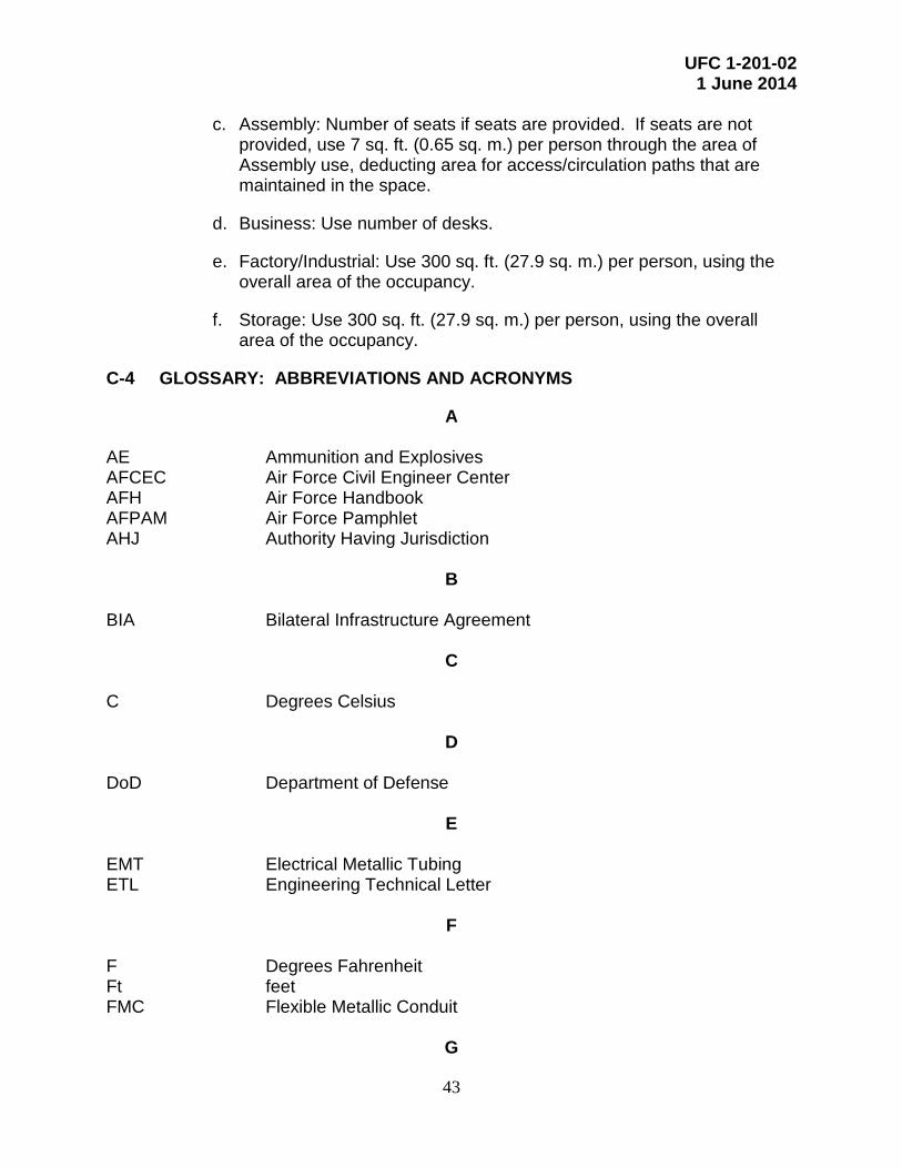
UFC 1-201-02 1 June 2014
43
c. Assembly: Number of seats if seats are provided. If seats are not provided, use 7 sq. ft. (0.65 sq. m.) per person through the area of Assembly use, deducting area for access/circulation paths that are maintained in the space.
d. Business: Use number of desks.
e. Factory/Industrial: Use 300 sq. ft. (27.9 sq. m.) per person, using the overall area of the occupancy.
f. Storage: Use 300 sq. ft. (27.9 sq. m.) per person, using the overall area of the occupancy.
C-4 GLOSSARY: ABBREVIATIONS AND ACRONYMS
A AE Ammunition and Explosives AFCEC Air Force Civil Engineer Center AFH Air Force Handbook AFPAM Air Force Pamphlet AHJ Authority Having Jurisdiction
B BIA Bilateral Infrastructure Agreement
C C Degrees Celsius
D DoD Department of Defense
E EMT Electrical Metallic Tubing ETL Engineering Technical Letter
F F Degrees Fahrenheit Ft feet FMC Flexible Metallic Conduit
G

UFC 1-201-02 1 June 2014
44
GFCI Ground Fault Circuit Interrupt GRS Galvanized Rigid Steel
H H Height HID High Intensity Discharge HN Host Nation HNFA Host Nation Funded Construction Agreements HQMC Headquarters, Marine Corps HQUSACE Headquarters, United States Army Corps of Engineers HVAC Heating, ventilation, and air conditioning
I
IBC International Building Code IEEE Institute of Electrical and Electronics Engineers IMT Intermediate Metal Conduit In inch(es)
J JFC Joint Forces Commander JFOB Joint Forward Operations Base JP Joint Publication
L L length
M
m meter MIL-STD Military Standard mm millimeter
N NAVFAC Naval Facilities Engineering Command NAVFACENGCOM Naval Facilities Engineering Command NCO Non-commissioned Officer NEC National Electrical Code NFPA National Fire Protection Association

UFC 1-201-02 1 June 2014
45
P PCB polychlorinated biphenyl PPE Personal Protective Equipment PVC Polyvinyl chloride
S SOFA Status of Forces Agreement Sq. ft. square feet Sq. m. square meter
T TM Technical Manual
U UFC Unified Facilities Criteria U.S. United States USACE United States Army Corps of Engineers
V
VA Volt-ampere Vol Volume
W W width

UFC 1-201-02 1 June 2014
46
This Page Intentionally Left Blank

UFC 1-201-02 1 June 2014
47
APPENDIX D PRELIMINARY EVALUATION CHECKLIST
This Preliminary Evaluation checklist can be printed and used to assess existing facilities being considered for occupancy up to 90 days.

Preliminary Evaluation Checklist for Building Occupancy BUILDING DESCRIPTION: LOCATION: BLDG NO.: INSPECTOR: DATE/TIME:
48
General Personal Safety: Basic parameters to ensure safety when conducting occupancy assessments:
• Always wear standard issue personal protective equipment (PPE).
• Work in teams of at least 2 or have means of communication to response personnel
• Be alert for falling objects or tripping hazards Equipment: See Chapter 3 of the UFC for a list of equipment typically used for these evaluations.
Evaluation Process: Complete the checklist in the order it is arranged. Initially assess the building from the exterior. Then perform an initial interior walk-thru to expeditiously assess issues that may prevent occupancy. Finally, assess interior discipline-specific issues.
PRELIMINARY EVALUATION SUMMARY Complete summaries below and outline results of the evaluation regarding the following:
• Any conditions discovered that restrict/prevent occupancy • Any required or recommended mitigations to allow safe occupancy • Any conditions requiring “Reachback” assistance
Entries must be signed by each inspector and the Officer in Charge If resources are available, Preliminary and Detailed Evaluations should be performed together.
Discipline/System Inspection Summary Structural Systems
Inspector Signature: Fire Protection
Inspector Signature: Electrical/ Telecom
Inspector Signature: Mechanical/ Plumbing
Inspector Signature:
INSPECTION RECOMMENDATION PRELIMINARY EVALUATION Building can be occupied as-is for 90 days (no deficiencies found) Building can be occupied for 90 days following mitigations summarized above Prior to initial occupancy “Reachback” is required as outlined above Building occupancy can be extended for an additional 90-day period
Officer-in-Charge Signature:__________________________

Preliminary Evaluation Checklist for Building Occupancy BUILDING DESCRIPTION: LOCATION: BLDG NO.: INSPECTOR: DATE/TIME:
49
PRELIMINARY EVALUATION Note: The Preliminary Evaluation is a limited assessment to identify extreme hazards that pose an imminent risk to life safety or health, and to provide limited safety for immediate but limited-use occupancy. Due to the minimal scope of the preliminary evaluation, significant risks may exist even with a successful evaluation. Valid for 90 days. For extended occupancy, Primary and Detailed Evaluations can be performed concurrently
BUILDING CHARACTERISTICS Proposed Building Usage Number of Stories Building Height Footprint Area (square feet) Past Building Usage Type of Construction Year Constructed GPS Coordinates
HISTORY OF BUILDING/FACILITY DATA Note: the following valuable information can be obtained from Host Nation or local residents
Building documentation (as-builts) available? When was building last occupied? Who lived/worked in building? Are prior occupants still in area? What activities were performed in the building?
BUILDING SKETCH

Preliminary Evaluation Checklist for Building Occupancy BUILDING DESCRIPTION: LOCATION: BLDG NO.: INSPECTOR: DATE/TIME:
50
INSPECTOR:
CONDITION ASSESSED CONDITION
FOUND? SUGGESTED ACTION Exterior Assessment Collapse or partial collapse of building Do not enter Building noticeably leaning Do not enter Building shifted off foundation Do not enter Numerous cracks more than 1/8 in. wide in exterior walls
Do not enter
Building has significant blast or fire damage Do not enter Items that could fall on personnel - Loose pieces of building walls - Broken or loose parapets - Built up snow or ice on roof - Damaged low roof over entrance
Remove loose items or block access to areas under loose items.
Downed power lines De-energize power systems Damaged or displaced gas lines Shut off gas, or vacate area Signs of previous industrial operations or hazardous material/waste release. Signs of hazardous material/waste releases include: - Open or damaged containers - Observed spills or releases - Detection of odors or physical reactions (e.g., dizziness, nausea, eye/skin irritation) - Broken or ruptured piping
Do not enter, report in accordance with reporting requirements
Partial control of site by DoD Do not occupy unless control allows safe occupancy Initial Walk-Thru
Partial control of building by DoD Do not occupy unless security controls allow safe occupancy
Existence of unexploded ordnance, explosives, or chemicals
Evacuate and report in accordance with reporting requirements
Rodent, insect or animal infestations Do not occupy Waste, sewage or standing water in bldg. Do not occupy Signs of excessive mold Do not occupy Exposed/disturbed insulation Do not occupy unless determined not to be
hazardous Isolated collapse of building structure Evacuate collapsed area Open flames Evacuate Evidence of gas leaks Evacuate Inspect roof for loose equipment and falling hazards Mitigate hazard Structural Interior Issues Walls or columns visibly leaning, bent, cracked, or broken
Do not occupy
Floor or roof structural members sagging, cracked, broken, or separated from their supports
Do not occupy or if problem areas are localized, block access to damaged areas.
Structural members significantly deteriorated – rust, rot, or infested by termites
Do not occupy or if problem areas are localized, block access to damaged areas.
Structural members badly burned or twisted/sagging from fire
Do not occupy or if problem areas are localized, block access to damaged areas.

Preliminary Evaluation Checklist for Building Occupancy BUILDING DESCRIPTION: LOCATION: BLDG NO.: INSPECTOR: DATE/TIME:
51
CONDITION ASSESSED CONDITION
FOUND? SUGGESTED ACTION Items that could fall on personnel - Loose pieces of walls, ceilings, or finishes - Loose ductwork or overhead equipment - Other miscellaneous non-structural items
Remove loose items or block access to areas under loose items.
Fire Protection Issues Building occupied at levels more than 2 stories above grade Building occupied in a sub-basement (more than one story below grade). (Occupancy includes use of the space for other than mechanical/electrical rooms, lookout/security rooms, or storage rooms)
Locate occupied spaces of building only 2 stories above grade. Do not occupy sub-basements. Conduct detailed evaluation to determine if allowable to occupy higher stories.
Areas inside buildings occupied by fueled airplanes or vehicles
Mitigation measures (complete one of the following prior to and during occupancy):
1) Remove airplanes, vehicles from building, 2) Remove fuel from this equipment, store
fuel outside building Hazardous Areas or equipment that is not enclosed by walls on all sides (cut-off rooms). - An area with flammable liquid use or storage, fuel
storage, or flammable gas storage - Battery storage with batteries sized over 10 cu. ft.
(0.283 m3) in volume (total size) - An area with fuel-fired equipment (boilers, air
handlers, hot water heaters) - An area with Oil-filled transformers - Areas with over 1,000 sq. ft. (92.9 sq. m) of stored
combustible materials (paper, plastic, or wooden materials)
- An area with combustible storage stacked over 12 ft. (3.66 m) high above the floor
-An area with hazardous waste storage (flammable, corrosive or noxious chemicals)
Prior to occupancy:
1) Remove flammable liquids use and storage from premise,
2) Remove hazardous equipment from service,
3) For storage areas, remove storage, or provide a minimum 50 ft. (15.2 m) of space separation between occupied space and storage and a 24 hour fire watch,
4) Remove hazardous waste from building prior to occupancy.

Preliminary Evaluation Checklist for Building Occupancy BUILDING DESCRIPTION: LOCATION: BLDG NO.: INSPECTOR: DATE/TIME:
52
CONDITION ASSESSED CONDITION
FOUND? SUGGESTED ACTION Deficient Egress Issues exist, including: - Number of exits from any building story is less
than two (exits are doors to the exterior, an exterior stairway, or an interior stairway enclosed by walls)
- Dead-bolt type locks on egress doors from occupied spaces - Paths to exits from occupied spaces through
storage areas with no other exit path available - Paths to exits from occupied areas through
hazardous areas with no other exit path available
- Paths to exits are blocked by storage. - Exit stairs are used for storage.
Prior to occupancy:
1) Do not occupy a story with less than 2 exits.
2) Remove dead bolt type locks from egress doors.
3) Remove storage or hazardous process from building.
4) Remove hazardous process from service. 5) Provide additional exit option avoiding
storage area or hazardous area. 6) Remove storage from exit paths.
Exposed plastic foam insulation or corkboard on walls or ceilings in occupied spaces
Remove insulation or corkboard prior to occupancy
Mechanical and Plumbing Issues Sanitary piping and venting is not properly configured and traps are not sealed
Occupy, but do not use systems and apply warning signs
Roof drainage and overflow drainage piping show evidence of leakage
Occupy, but perform any readily achievable drainage system repairs prior to occupancy
Roof drains show evidence of blockages Occupy , but remove any roof drain blockages prior to occupancy
Fuel-fired heating system is in operation Occupy, but de-energize heating system until Detailed Evaluation is completed
Hazardous or chemical storage areas do not have appropriate containment, ventilation and safety features
Occupy, but do not store chemicals in these areas
*Electrical and Telecommunications Systems
Is existing electrical system de-energized Do not energize electrical system until Detailed Evaluation is completed
Is existing electrical power system energized and was facility recently occupied
Do not de-energize and do not use electrical power system until proven safe through completion of a Detailed Evaluation
Survey the building and look for any exposed conductors.
Occupy, close off any rooms with exposed wiring and provide a warning sign. Where exposed wiring is found in areas that cannot be closed off, de-energize the systems per info below.
*Note: De-energized existing electrical systems cannot be energized until a Detailed Evaluation is conducted. Energized existing electrical systems cannot be used until a Detailed Evaluation is conducted.
Additional Notes on Preliminary Evaluation Issues and Mitigation Actions:

UFC 1-201-02 Draft – 1 January 2014
53
APPENDIX E DETAILED EVALUATION CHECKLIST
This checklist can be printed and used to assess existing facilities being considered for extended occupancy up to 5 years. The checklist covers Detailed Evaluations and correlates to the technical content within Chapter 4 of this UFC.

Detailed Evaluation Checklist for Building Occupancy BUILDING DESCRIPTION: LOCATION: BLDG NO.: INSPECTOR: DATE/TIME:
54
DETAILED EVALUATION SUMMARY Complete the summaries below and outline the results of the building evaluation regarding the following conditions:
• Any conditions discovered that restrict/prevent occupancy
• Any required or recommended mitigations to allow safe occupancy
• Any conditions requiring “Reachback” assistance Entries must be signed by each inspector and the Officer-in-Charge. Discipline/System Inspection Summary Structural Systems
Inspector Signature: Fire Protection
Inspector Signature: Electrical/ Telecom
Inspector Signature: Mechanical/ Plumbing
Inspector Signature: INSPECTION RECOMMENDATION DETAILED EVALUATION Building can be occupied as-is for 5 years (no deficiencies found) Building can be occupied for 5 years following mitigations summarized above Prior to extended occupancy “Reachback” is required as outlined above
Officer-in-Charge Signature:__________________________

Detailed Evaluation Checklist for Building Occupancy BUILDING DESCRIPTION: LOCATION: BLDG NO.: INSPECTOR: DATE/TIME:
55
DETAILED EVALUATION Note: The Detailed Evaluation identifies hazards that pose near-term risks to life safety and health, and provides minimal safety and habitability for longer-term occupancy (5 years) than the preliminary evaluation. The Detailed Evaluation does not address all safety and habitability requirements that are specified in UFC 1-201-01 and addressed in an Engineering Assessment. For items answered as “Yes”, see section number reference in UFC for mitigation options.
BUILDING CHARACTERISTICS Proposed Building Usage Number of Stories Building Height Footprint Area (square feet) Past Building Usage Type of Construction Year Constructed GPS Coordinates
BUILDING SKETCH

Detailed Evaluation Checklist for Building Occupancy BUILDING DESCRIPTION: LOCATION: BLDG NO.: INSPECTOR: DATE/TIME:
56
STRUCTURAL SYSTEMS INSPECTOR:
CONDITION ASSESSED CONDITION
FOUND? MITIGATION SECTION # SUGGESTED MITIGATION
Overall Structural Damage Collapse or partial collapse 4-3.3 Building or story leaning more than 4 in. (100 mm) or H/200 (H=bldg or story height in inches)
4-3.3
Foundation damage or building shifted off foundation
4-3.3
Building in zone of suspected slope instability, sinkholes, or erosion
4-3.3
Building below region of potential landslide 4-3.3 Significant exterior wall cracks or offsets 4-3.3 Significant blast or fire damage 4-3.3 Items that could fall on personnel - Loose pieces of parapets and facades - Built up snow or ice on roof - Damaged or poorly attached entrance canopies
4-3.3
Damage to Structural Framing Components
Leaning: Columns, piers, or bearing walls more than 4 in. (100 mm ) or H/200 (H=bldg or story height in inches)
4-3.3
Buckling: Columns, piers, diagonal bracing, or bearing walls
4-3.3
Damage to horizontal framing members: Cracking with vertical or horizontal displacement in any horizontal framing member.
4-3.3
Roof or floor framing sloping or sagging in excess of L/180, or separation from walls or other supports
4-3.3
Damage to vertical framing members: Cracking with vertical or horizontal Displacement in any vertical framing member.
4-3.3
Connections: Visible damage to connections
4-3.3
Bracing: Broken, bent, or damaged bracing members
4-3.3
Connection to foundation: Damaged connections between structural members and foundations.
4-3.3
Fire: Section loss, twisting, warping, or spalling in structural members from fire
4-3.3

Detailed Evaluation Checklist for Building Occupancy BUILDING DESCRIPTION: LOCATION: BLDG NO.: INSPECTOR: DATE/TIME:
57
STRUCTURAL SYSTEMS INSPECTOR:
CONDITION ASSESSED CONDITION
FOUND? MITIGATION SECTION # SUGGESTED MITIGATION
Deterioration: Rotting or insect infested wood, corroded steel, spalled concrete, freeze-thaw damaged masonry or concrete.
4-3.3
Falling Hazards: Any loose or damaged structural framing, finishes, equipment, or other items that could fall on occupants
4-3.3
Additional Notes on Structural Systems and Mitigation Actions:

Detailed Evaluation Checklist for Building Occupancy BUILDING DESCRIPTION: LOCATION: BLDG NO.: INSPECTOR: DATE/TIME:
58
DETAILED EVALUATION (continued)
FIRE PROTECTION ISSUES
INSPECTOR:
CONDITION ASSESSED CONDITION
FOUND? MITIGATION SECTION # SUGGESTED MITIGATION
Conditions Requiring Field Mitigation or Reachback
Building separation not adequate. 4-4.2.1 Seal up openings in exterior walls.
Planned occupancy of floors more than 3 stories above grade.
4-4.2.2
Occupy building only to a maximum of 3 stories above grade. Contact Reachback for assistance.
Planned occupancy of floors more than 2 stories above grade in building with any of the following: a. Combustible construction. b. No automatic sprinkler system c. Vertical openings connecting
more than 2 stories.
4-4.2.2 Occupy building only to a maximum of 2 stories above grade. Contact Reachback for assistance.
Planned occupancy of basement levels by billeting, institutional or assembly occupancies.
4-4.1.2 Occupy basement levels by occupancies
other than billeting, institutional or assembly.
Planned occupancy of sub-basement levels.
4-4.1.2 Do not occupy sub-basement levels.
Travel distance to exits exceeds allowable maximum distance.
4-4.2.4
Do not occupy remote space, occupy space by an occupancy with longer allowable travel distance, provide an additional exit option, or provide means of escape.
Dead end corridors longer than 25 ft. (7.6 m).
4-4.2.4
Provide additional exit path, means of escape, or do not occupy area with dead end corridor.
Less than 2 exits on each occupied level.
4-4.2.4 Provide additional remote exit or remote means of escape. Do not occupy floor with less than 2 exits.
Suite over 2,000 sq. ft. (186 sq m) with single exit path.
4-4.2.4 Provide additional remote exit path, remote means of escape, or do not occupy this area.
Assembly occupancy with less than 2 exit paths available from space.
4-4.2.4 Provide additional remote exit path or relocate assembly occupancy
Exit capacity is insufficient for any occupied area.
4-4.2.4 Provide additional exits, means of escape, or only allow what the exit capacity allows.
Exits blocked, obstructed, or enclosed stairs contain storage.
4-4.2.4 Remove obstructions or storage
Exit doors are locked, or not under control of occupants.
4-4.2.4 Remove locks or do not occupy area not controlling egress.
Exit paths routed from occupied areas through hazardous areas or areas of storage.
4-4.2.4 Provide exiting so it is not routed through
hazardous areas or storage.

Detailed Evaluation Checklist for Building Occupancy BUILDING DESCRIPTION: LOCATION: BLDG NO.: INSPECTOR: DATE/TIME:
59
FIRE PROTECTION ISSUES
INSPECTOR:
CONDITION ASSESSED CONDITION
FOUND? MITIGATION SECTION # SUGGESTED MITIGATION
Billeting occupancy without an automatic sprinkler system.
4-4.2.5
Area < 7,000 sq. ft. (650 sq. m.): Provide fire watch, direct exits to the exterior, subdividing walls separating this billeting area from other areas of the building including other billeting areas, and smoke alarms in billeting units; or limit occupancy to less than 10 beds. Area > 7,000 sq. ft. (650 sq. m.): Contact Reachback
Billeting occupancy with no installed fire evacuation alarm system.
4-4.2.6 Provide fire watch.
Kitchen grill/fryer with no hood. 4-4.2.5 Remove kitchen grill from service, or provide fixed wall around kitchen area.
Kitchen hood with no fixed fire suppression system
4-4.2.5 Provide fixed wall around kitchen area.
Assembly occupancy with partial, or no fire alarm system in building.
4-4.2.6 Provide manual notification and a fire watch when occupied.
Institutional occupancy with partial, or no fire alarm system in building.
4-4.2.6 Provide manual notification and a fire watch.
Business occupancy over 5,000 sq. ft. (465 sq m) in basement, second or third floors with partial, or no fire alarm system in building.
4-4.2.6 Provide manual notification and a fire watch
when occupied.
Hazardous areas or hazardous equipment are not segregated from other occupancies by fixed walls.
4-4.2.7
Remove hazardous equipment from service, relocate equipment or materials, or provide fire suppression system (kitchen hood system) or automatic sprinkler system.
Hazardous or chemical storage areas are not provided with containment or ventilation.
4-4.2.7 Remove hazardous material storage.
Interior finishes consists of exposed combustible (plastic, foam) insulations, cork board, fabric assemblies, or combustible decorations.
4-4.2.8
Remove combustible finishes or cover with noncombustible fire barrier. Remove combustible decorations.
Vertical openings connecting more than 2 stories.
4-4.2.9, 4.4.2.2
Provide gypsum wallboard around one level to limit floor opening to 2 stories. See building height restrictions also.
Additional Notes on Fire Protection Issues and Mitigation Actions:

Detailed Evaluation Checklist for Building Occupancy BUILDING DESCRIPTION: LOCATION: BLDG NO.: INSPECTOR: DATE/TIME:
60
Partial Definition List: Building Separation: The horizontal separation distance between the building under consideration and neighboring buildings on all sides. For multiple buildings on the same compound, assume an imaginary line halfway between buildings. The distance from building under consideration to adjacent existing buildings, or from the building under consideration to the imaginary line, whichever is shorter, is the fire separation distance.
Dead end corridor: A section of corridor that does not lead to an exit stair or an exterior exit door. For example, for a building with 2 interior exit stairs and a corridor connecting these 2 stairs, any extension length of the corridor “outboard” of the 2 exit stairs is a dead end corridor length. The maximum dead end corridor limit for all occupancies of this document is 25 feet (7.6 m).
Egress: The path of travel for persons from occupied areas through rooms or exits to reach areas outside of a building.
Exit: A door in the exterior wall of the building accessing the outdoors, a stairway interior to the building that is enclosed by walls and leads to the outdoors, or a stairway located on the exterior of the building, leading to the outdoors.
Exit Capacity: The calculated number of persons a given exit component (stair or exit door) can accommodate for determining the maximum allowable occupant load. Door width is the width of the opening through the door. Stair width is the width of a flight of stairs. If the stairs vary in width, measure at its narrowest point. Stairs are assumed to have inconsistent rise and run; however the run should not be less than 6 inches (127 mm).
If the egress path consists of a door and a stair, the occupant load is limited by the smaller of the two exit capacities. For example, if the door is 34 inches wide (exit capacity of 145) and the stair is 44 inches wide (exit capacity of 120), the stair is the limiting factor for determining the Exit Capacity.
Where there are two or more exits from a room or floor, the maximum allowable occupant load is determine by adding the exit capacities for each exit from that room or floor.
An Occupant Load greater than the Exit Capacity is unsafe.
Occupied Spaces: Spaces that are normally used by personnel other than building maintenance persons. Occupied spaces do not include unmanned storage rooms, lookout towers, guard positions, mechanical/electrical equipment rooms, or computer server rooms.
Occupancy: For purposes of this document, occupancy consists of one or more of the following building uses: a) Billeting (sleeping areas with more than 10 beds) b) Institutional (hospital, confinement) areas over 1,000 sq. ft. (92.9 sq. m.) c) Assembly (gathering places, cafeterias, etc.) exceeding 500 sq. ft. (46.5 sq. m.) d) Business (offices) exceeding 1,000 sq. ft. (92.9 sq. m.) e) Factory-Industrial (shops, mechanical spaces) areas over 1,000 sq. ft. (92.9 sq. m.) f) Storage (including hangars and parking garages) areas over 1,000 sq. ft. (92.9 sq. m.)
Exit Capacity Clear Width Occupants per
in (mm) Door Stair 24 (610) 100 65 28 (710) 120 75 30 (762) 130 80 32 (812) 135 85 34 (863) 145 90 36 (915) 155 100 40 (1,015) 170 110 44 (1,117) 185 120
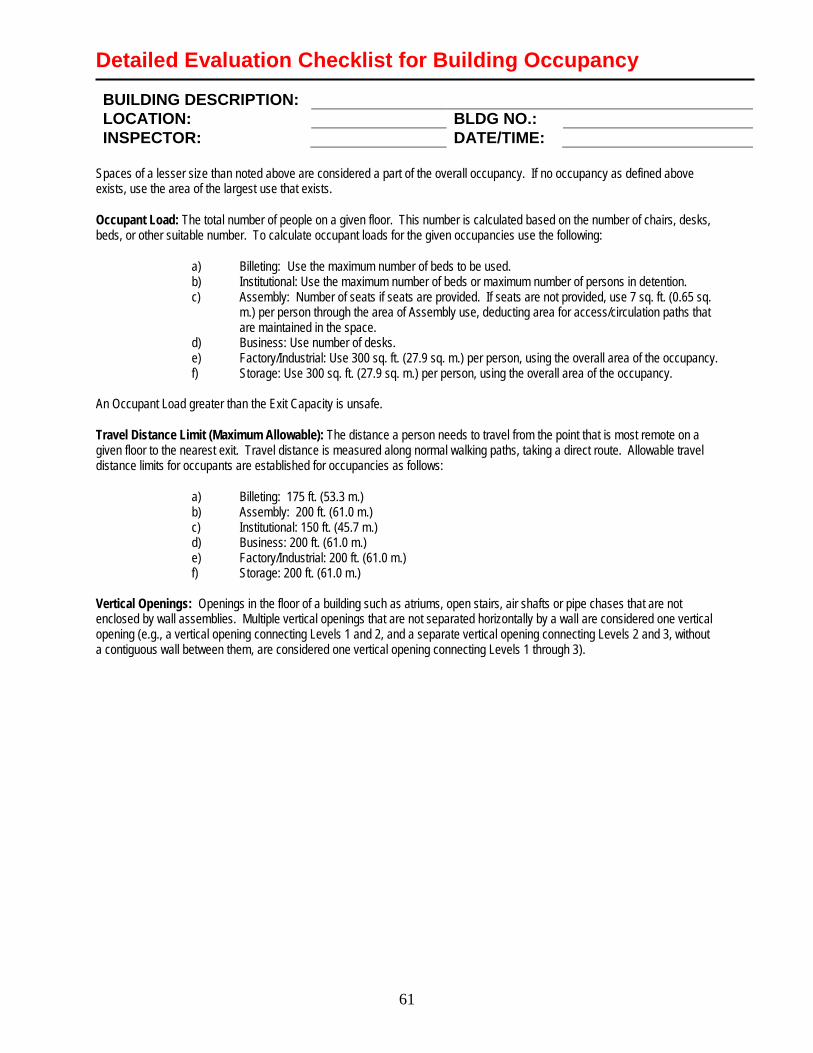
Detailed Evaluation Checklist for Building Occupancy BUILDING DESCRIPTION: LOCATION: BLDG NO.: INSPECTOR: DATE/TIME:
61
Spaces of a lesser size than noted above are considered a part of the overall occupancy. If no occupancy as defined above exists, use the area of the largest use that exists.
Occupant Load: The total number of people on a given floor. This number is calculated based on the number of chairs, desks, beds, or other suitable number. To calculate occupant loads for the given occupancies use the following:
a) Billeting: Use the maximum number of beds to be used. b) Institutional: Use the maximum number of beds or maximum number of persons in detention. c) Assembly: Number of seats if seats are provided. If seats are not provided, use 7 sq. ft. (0.65 sq.
m.) per person through the area of Assembly use, deducting area for access/circulation paths that are maintained in the space.
d) Business: Use number of desks. e) Factory/Industrial: Use 300 sq. ft. (27.9 sq. m.) per person, using the overall area of the occupancy. f) Storage: Use 300 sq. ft. (27.9 sq. m.) per person, using the overall area of the occupancy.
An Occupant Load greater than the Exit Capacity is unsafe.
Travel Distance Limit (Maximum Allowable): The distance a person needs to travel from the point that is most remote on a given floor to the nearest exit. Travel distance is measured along normal walking paths, taking a direct route. Allowable travel distance limits for occupants are established for occupancies as follows:
a) Billeting: 175 ft. (53.3 m.) b) Assembly: 200 ft. (61.0 m.) c) Institutional: 150 ft. (45.7 m.) d) Business: 200 ft. (61.0 m.) e) Factory/Industrial: 200 ft. (61.0 m.) f) Storage: 200 ft. (61.0 m.)
Vertical Openings: Openings in the floor of a building such as atriums, open stairs, air shafts or pipe chases that are not enclosed by wall assemblies. Multiple vertical openings that are not separated horizontally by a wall are considered one vertical opening (e.g., a vertical opening connecting Levels 1 and 2, and a separate vertical opening connecting Levels 2 and 3, without a contiguous wall between them, are considered one vertical opening connecting Levels 1 through 3).

Detailed Evaluation Checklist for Building Occupancy BUILDING DESCRIPTION: LOCATION: BLDG NO.: INSPECTOR: DATE/TIME:
62
DETAILED EVALUATION (continued)
PLUMBING AND MECHANICAL SYSTEM ISSUES INSPECTOR:
CONDITION ASSESSED CONDITION
FOUND? MITIGATION SECTION # SUGGESTED MITIGATION
Visual Inspection and Tests Domestic water unsafe based on testing? 4-5.2.1 Any evidence of plumbing systems leaking?
4-5.2.1
Any domestic water system cross connections?
4-5.2.1
HVAC system does not function properly, is unsafe or not operational?
4-5.2.5
Exposed or above-ceiling HVAC pipes leaking?
4-5.2.6
Visual Inspection and Field Surveys Hot water systems are not configured properly or do not have appropriate safety equipment?
4-5.2.2
Hot water equipment does not function properly or has inappropriate temperature settings?
4-5.2.2
Sanitary piping and venting is not configured properly and/or not all traps are sealed?
4-5.2.3
Vents through roof show signs of blockage?
4-5.2.3
Roof and overflow drainage systems are obstructed by debris or not configured properly?
4-5.2.4
Fuel system components are inappropriate or unsafe to operate?
4-5.2.2
Additional Notes on Plumbing and Mechanical System Issues and Mitigation Actions:

Detailed Evaluation Checklist for Building Occupancy BUILDING DESCRIPTION: LOCATION: BLDG NO.: INSPECTOR: DATE/TIME:
63
DETAILED EVALUATION (continued)
ELECTRICAL SYSTEM ISSUES
INSPECTOR:
CONDITION ASSESSED CONDITION
FOUND? MITIGATION SECTION # SUGGESTED MITIGATION
Field Measurements and Calculations
Equipment short circuit ratings are less than minimum requirements?
4-6.2.1
Distribution System Grounding does not meet NFPA 70 (60 Hz) or BS 7671 (50 Hz) and UFC 3-550-01?
4-6.2.2
Branch circuit conductors, conduit and breakers’ sizes do not comply with NFPA 70(60 Hz) or BS 7671 (50 Hz)?
4-6.2.3
Feeder circuit conductors, conduit and/or breakers’ sizes do not comply with NFPA 70 (60 Hz) or BS 7671 (50 Hz)?
4-6.2.3
Visual Inspection and Field Surveys
Lightning Protection System is not installed per NFPA 780.
4-6.2.4
Raceway applications do not comply with NFPA 70? (60 Hz) or BS 7671 (50 Hz)
4-6.2.5
Branch and Feeder conductors; installations do not comply with NFPA 70? (60 Hz) or BS 7671 (50 Hz)
4-6.2.3
Emergency and Exit Lighting equipment and placements do not comply with NFPA 101 and IBC?
4-6.2.6
Transformers’ application and installation do not comply with NFPA 70(60 Hz) or BS 7671 (50 Hz)?
4-6.2.7
Grounding type and GFCI receptacles do not comply with NFPA 70(60 Hz) or BS 7671 (50 Hz)?
4-6.2.8
Procedural Reviews Military unit does not have appropriate circuit lock-out procedures?
4-6.2.9
Additional Notes on Electrical System Issues and Mitigation Actions:

Detailed Evaluation Checklist for Building Occupancy BUILDING DESCRIPTION: LOCATION: BLDG NO.: INSPECTOR: DATE/TIME:
64
DETAILED EVALUATION (continued)
TELECOMMUNICATIONS ISSUES
INSPECTOR:
CONDITION ASSESSED CONDITION
FOUND? MITIGATION SECTION # SUGGESTED MITIGATION
Distribution System Grounding does not meet NFPA 70 (60 Hz) or BS 7671 (50 Hz) and UFC 3-550-01?
4-6.2.2
Additional Notes on Telecommunications System Issues and Mitigation Actions: ADDITIONAL NOTES AND ACTION ITEMS
NOTES ACTIONS
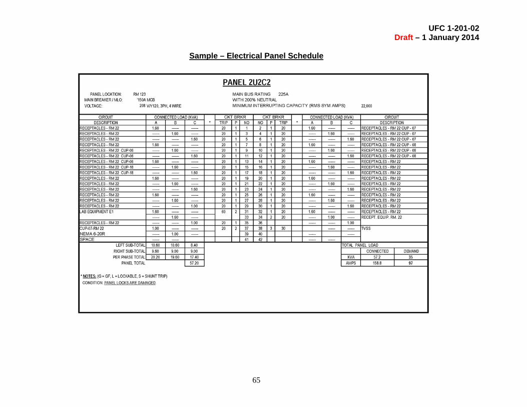
UFC 1-201-02 Draft – 1 January 2014
65
Sample – Electrical Panel Schedule

UFC 1-201-02 Draft – 1 January 2014
66
Blank – Electrical Panel Schedule

UFC 1-201-02 Draft – 1 January 2014
67
Sample – Electrical One-Line Diagram