udc series vol 11 - ttetec.eu
TRANSCRIPT


2
Features Revolutionary Diamond coating offers excellent cutting performance
A Strong and Powerful Diamond Coating - UDC!!
Direct Milling of Cemented Carbide - No Grinding!
The normal expectation when milling Cemented Carbide would be a powdered swarf….
By using a deep cut into the Cemented Carbide, UDCB creates a “fan shaped” chip, just like cutting steel!
UDCB R0.5 Ball End Mill
Spindle Speed
Feed Rate
Coolant
30,000 min-1
300 mm/min
0.1 mm
Air Blow
“Fan-shaped” c
hip
created
Tool
Axial Depth
(a) Inside view of a curled chip (surface side)
(b) Outside view (tool / rake side)
1
2
UDCB 2010-0070 R0.5×0.7
VM-40 (90HRA)
Chip size
UDCB chip evacuation
UNION TOOL's Diamond film that coated using the hot filament
CVD method is developed to improve hardness and durability,
with outstanding adhesion to the cutting tool. Using fine particle
composition control, the UDC coating has dramatically improved
hardness and durability.
Sandblasting tests the film adhesion and wear resistance
UNION TOOL
Competitor
The film is sandblasted and
its resistance to peeling
measured by time
UDC
Tool L
ife (
DIA
CO
AT
equals
100%
)
Coating Patented in Japan
Special high-performance Diamond film.
A new Diamond coating developed to improve hardness and durability, with outstanding adhesion to the cutting tool.
DIA COAT
ap

3
Revolutionary Diamond coating offers excellent cutting performance“Cutting” Cemented Carbide is achieved using the latest Diamond coating - UDC新開発ダイヤモンドコート
EDM and UDCB Direct Milling Comparison
UDCB R3 Ball End MillDeep tapered circular pocket milling on Cemented Carbide
Case Study : Simulation of deep pocket milling with UDCB R3
After milling
80,000
70,000
60,000
50,000
40,000
30,000
20,000
10,000
0
Machining Cost
Machining Cost
hCycle Time
Cycle Time
6
5
4
3
2
1
0EDM Direct Milling
One tool-Milling VM-40-removed1.4cc of material!
UDCB Advantages
・80% cycle time reduction・60% machining cost reduction・No substrate damage - Reduces polishing time - unlike EDM・Excellent accuracy of the finished part
EDM
Qty/h
Total
Making
Copper
Electrode
Tool
Material
Machine
Operator
Machine
OperatorEDM
3
1
2
2
3
3
Unit Price Total
3,000
2,000
5,000
8,000
5,000
8,000
9,000
2,000
10,000
16,000
15,000
24,000
76,000
2
3
(h)Cycle Time
Direct Milling
Qty/h
Total
MillingCarbide
Tool UDCB
Machine
Operator
1
1
1
Unit Price Total
17,500
5,000
8,000
17,500
5,000
8,000
30,500
1
1
(h)Cycle Time
Tool
Spindle Speed
Feed Rate
Axial Depth
Radial Depth
Coolant
Cycle Time
Material Removal Volume
UDCB 2060-0420 R3x4.2
20,000 min-1
200 mm/min
0.2 mm
0.4 mm
Air Blow
52 min
1,400 mm3 1.4 cc 26.9 mm3/min
VM-40 (90HRA)
Work Sample Size
UDCB
Deep Milling Video
ap
ae

4
Spindle Speed
Feed Rate
Axial Depth
Coolant
ToolUDCB 2010-0070 R0.5×0.7
UDCBF 2010-0070 R0.5×0.7
30,000 min-1
300 mm/min
0.1 mm
Air Blow Nozzle
Sharp cutting edge
with special
treatment
Chip pocket designed
on tool tip
How to Choose
UDC
Initial Cost Saving Better Surface Finish / Longer Tool Life
Ball UDCB / UDCLB
Radius UDCLRS
Ball UDCBF / UDCLBF
Radius UDCLRSF
VM-40 (90HRA)
Special treatment on cutting edge reduces cutting resistance!
Cemented Carbide Cutting Resistance Comparison using UDCBF R0.5x0.7 Ball End Mill
①New UDC
Diamond Coating
②Sharp cutting
edge
③Chip pocketdesigned on
tool tip
"F (Fine)" Series offers①Seamless surface finish
②Minimized edge chipping
③More material removal volume
F
"F (Fine)" Series Advantages
X Direction Y Direction Z Direction
ap

5
Cemented Carbide 20 15° Taper milled with UDCBF R0.5x0.7 Ball End Mill1
2
3
UDCB UDCBF
UDCB UDCBF
Spindle Speed
Feed Rate
Axial Depth
Radial Depth
Coolant
Cycle Time
30,000 min-1
300 mm/min
0.05 mm
0.02 mm
Air Blow Nozzle
55 min 5 sec
30,000 min-1
300 mm/min
0.05 mm
0.25 mm
Air Blow Nozzle
Tool
UDCB 2010-0070 R0.5×0.7UDCB 2010-0070 R0.5×0.7UDCLB 2010-0250 R0.5×2.5×0.7UDCLBF 2010-0250 R0.5×2.5×0.7UDCLB 2010-0400 R0.5×4×0.7UDCLBF 2010-0400 R0.5×4×0.7
Spindle Speed
Feed Rate
Axial Depth
Radial Depth
Coolant
ToolUDCB 2010-0070 R0.5×0.7
UDCBF 2010-0070 R0.5×0.7
Spindle Speed
Feed Rate
Axial Depth
Radial Depth
Coolant
30,000 min-1
300 mm/min
0.02 mm
0.05 mm
Air Blow Nozzle
ToolUDCB 2010-0070 R0.5×0.7
UDCBF 2010-0070 R0.5×0.7
Mate
rial R
em
oval V
olu
me
mm
3
All Flute
2.5mm
Effective Length
4.0mm
Effective Length
VF-10 (93HRA)
Cemented Carbide Comparison of Edge Chipping using UDCBF R0.5x0.7 Ball End Mill
Cemented Carbide Material Removal Volume Comparison on Roughing using UDCBF & UDCLBF
VM-40 (90HRA)
VM-40 (90HRA)
Edge chipping on work material
Surface
Side
Surface
Side
Milling ExamplesSeamless surface finish
Minimized edge chipping
More material removal volume
15µm
-15µm Form accuracy Form accuracy
Gap
Milling direction
Milling direction
15µm
-15µm
UDCB: Coating damage on cutting edge
causes milling gap.
UDCBF: Uniform surface with excellent
dimensional accuracy.
ap
ae
ap
ae
ap
ae

6
Tool
Spindle Speed
Feed Rate
Axial Depth
Radial Depth
Coolant
Cycle Time
Material Removal Volume
0.05 mm
0.25 mm
43 min
86.3 mm3
0.028 mm
0.02 mm
2 h 17 min
12.0 mm3
UDCBF SeriesIndexable Insert Mold
Milling Video
4 VM-40 (90HRA)
30,000 min-1
300 mm/min
Air Blow Nozzle
Roughing Finishing
One End Mill for both roughing and finishing processes. Total 2 tools are used.
Tool after roughing Tool after finishing
Work sample after finishing
Surface Side
Surface Roughness
Size 20 × 20 × 10 mm
Ra: 0.054 µmRz: 0.408 µm
Ra: 0.051 µmRz: 0.399 µm
Ra: 0.068 µmRz: 0.520 µm
Cemented Carbide Indexable Insert Mold milled with UDCBF R0.5x0.7 Ball End Mill
Excellent surfa
ce quality!
Minimized edge chipping
UDCBF 2010-0070 R0.5×0.7
200.00 µ m
ap
ae

7
Total 16 15:04:32
Bevel Gear on Cemented Carbide of VU-70(83HRA) milled with UDCLB / UDCLBF R1・R1.5・R2
Binderless Cemented Carbide (90HRA~) Lens Array milled with UDCB R0.5 & R1 Ball End Mills
Milling Process
Size 25 × 25 mm
Milling Process
5 axis machining provides high quality curved surface.
Actual cycle time : 8 h 49 min
Coolant : Air blow
44 × 12.75 mmSize
The number of tool used for processing was 16 pieces, and the processing completed in 15 hours.
Coolant
: Air blow
Process
Z-Level High Efficiency Roughing
Z-Level Re-machining
Curve Control Along Surface
Z-Level Finishing
Z-Level Finishing
Tool
UDCB 2020-0140 R1 × 1.4
UDCB 2010-0070 R0.5 × 0.7
UDCB 2010-0070 R0.5 × 0.7
UDCB 2010-0070 R0.5 × 0.7
UDCB 2010-0070 R0.5 × 0.7
30,000
30,000
30,000
30,000
30,000
Spindle Speedmin-1
Feed Ratemm/min
300
300
300
300
300
0.1
0.05
0.3
0.2
0.02
5
6
VU-70 (83HRA)
mm mmLens Array
Milling Video
Available with
3axis machine !
Axial Depth Radial Depthap ae
UDCLB / UDCLBF
Direct milling for Cemented Carbide
Milling Video of Bevel Gear
SpindleSpeed
FeedRate
AxialDepth
RadialDepth
Finishing
Allowance
UDCLB 2040-0800 R2 × 8 8,250 300 0.5 0.2 0.03 3 2:12:31
UDCLB 2040-1000 R2 × 10 8,250 300 0.5 0.2 0.03 2 0:29:24
UDCLB 2030-0600 R1.5 × 6 11,000 280 0.38 0.15 0.03 1 0:22:33
UDCLB 2030-1000 R1.5 × 10 11,000 280 0.3 0.15 0.03 1 0:23:27
UDCLB 2030-1000 R1.5 × 10 11,000 280 (0.005) - 0.015 1 1:08:35
UDCLB 2030-1000 R1.5 × 10 11,000 280 (0.002) - 0.005 1 1:36:52
UDCLB 2020-0600 R1 × 6 16,500 420 0.12 0.05 0.015 1 0:52:28
UDCLB 2020-0800 R1 × 8 16,500 420 0.12 0.05 0.015 1 0:49:56
UDCLB 2020-0800 R1 × 8 16,500 420 0.09 - 0.005 1 1:09:32
UDCLBF 2020-0800 R1 × 8 20,000 200 - 0.12 0 1 0:41:20
UDCLBF 2020-0800 R1 × 8 20,000 200 (0.001) - 0 2 3:39:54
UDCLBF 2020-0800 R1 × 8 20,000 200 0.09 - 0 0:34:00
UDCLBF 2020-0800 R1 × 8 20,000 200 - 0.08 0 1:04:00
Process Tool Cycle TimeQuantity
Roughing
Roughing
Semi-finishing
Corner finishing
Finishing1
ap ae

8
8
Cemented Carbide Micro Needles milled with UDCLB R0.5x5 Long Neck Ball End Mill
Cemented Carbide Hexalobular milled with UDCLB R0.5x5 & R0.5x2 Long Neck Ball End Mills
Size: 9, 6 mm depth
Tool
Spindle Speed
Feed Rate
Axial Depth
Radial Depth
Coolant
Cycle Time
Material Removal Volume
UDCLB 2010-0500 R0.5×5 mm
R0.5 ball End Mill reaches deep into the
pocket (6 mm) with a great depth of cut.
Total 156 min
Total 274.4 mm3
Milling Conditions Process 1 Process 2 Process 3
Tool
Spindle Speed
Coolant
Cycle Time
Feed Rate
Axial Depth
Material Removal Volume
Radial Depth
RoughingMax 3.5 mm depth
RoughingMax 6 mm depth
UDCLB 2010-0500UDCLB 2010-0200
Air Blow
30,000 min-1
300 mm/min
0.05 mm
0.3 mm
58 min
152.8 mm3 120 mm3 1.6 mm3
0.25 mm
64 min
0.005 mm
0.03 mm
34 min
Finishing
※After finishing process
Max 2.5 mm depth Max 5.0 mm depth
30,000 min-1
300 mm/min
0.1 mm
Air Blow
0.05 mm
52 min
80.1 mm3
0.05 mm Bottom 0.02 mm
39 min
76.5 mm3
Overall size : 6 6 5 mm depth
Pin size : Tip diameter: 0.2 mm Pin length: 5 mm
Root diameter: 0.34 mm
7
8
One tool for and . Total 2 tools are used.
VF-20 (92.5HRA)
VF-20 (92.5HRA)
Super durabledeep milling!
Hexalobular Milling Video
Diameter 0.2 mm !Carbide micro pin.
ap
ae
ap
ae

9
Cemented Carbide UDCLRS 2xCR0.05x2 Long Neck Radius End Mill
10 Alumina / Zirconia Hexalobular milled with UDCB R0.5x0.7 Ball End Mill
After Finishing
Milling Conditions Roughing
20,000 min-1
750 mm/min
0.9 mm
0.01 mm
Air Blow
10 x 8 x 1.8 mm
16 m
Oil Mist
0.01 mm
144 mm3
20,000 min-1
100 mm/min
0.01 mm Bottom Surface0.9 mm Side
0.01 mm×5 Times
Finishing
Spindle Speed
Tool
Coolant
Milling Size
Milling Distance
Feed Rate
Axial Depth
Material Removal Volume
Radial Depth
Overhang
15 mm
Tool
Spindle Speed
Feed Rate
Axial Depth
Radial Depth
Coolant
Cycle Time
Material Removal Volume
UDCB 2010-0070 R0.5 × 0.7
Alumina / Zirconia
30,000 min-1
300 mm/min
0.05 mm
0.05 mm
Air Blow Nozzle
98 min
88.4 mm3 0.9 mm3/min
Work Material
One End Mill for both roughing and finishing processes. Total 2 tools are used.Ra: 0.069 m
Rz: 0.535 m
Cut-off length : 0.25 mm
Ra: 0.010 m
Rz: 0.078 m
Cut-off length : 0.08 mm
Hexalobular Size : 9 2.2 mm depth
Alumina Zirconia
Bottom Surface Appearance
Work sample after finishing
9 VM-40 (90HRA)
*Designed for the materials stated in the application chart of each series.
0.01 mm Bottom Surface0.05 mm Side
Mirror surface finishwith zero pits!
Side Milling Video
Versatile coating ! *
UDCLRS 2020-005-020
ap
ae
ap
ae

10
UDCBFSize ~
Ball type End Mills for milling Cemented Carbide and Hard Brittle (Non-Metallic) Materials. Upgraded version of UDCB.
New Diamond coating and tool geometry increase material removal volume.
Chip pocket designed on tool tip improves the surface finishing quality.
Special cutting edge treatment helps to avoid the edge chipping & level gap.
Recommended to use on semi-roughing & finishing process.
Fe
atu
res
The shank taper angle shown is not an exact value and to avoid
contact with the workpiece, we recommend the user controls the
precise value of this angle. Shank taper angle should not make
contact with the work piece.
Total 16 models Unit(mm)
Model
Number
Radius of
Ball Nose
R
Length
of Cut
Shank Taper
Angle
Bta
Overall
Length
L
Shank
Diameter
Ød
Price
¥
UDCBF 2002-0014 R0.1 0.14 16° 50 4 47,000
UDCBF 2003-0021 R0.15 0.21 16° 50 4 47,000
UDCBF 2004-0028 R0.2 0.28 16° 50 4 42,800
UDCBF 2005-0035 R0.25 0.35 16° 50 4 42,800
UDCBF 2006-0042 R0.3 0.42 16° 50 4 38,400
UDCBF 2007-0049 R0.35 0.49 16° 50 4 38,400
UDCBF 2008-0056 R0.4 0.56 16° 50 4 38,400
UDCBF 2009-0063 R0.45 0.63 16° 50 4 38,400
UDCBF 2010-0070 R0.5 0.7 16° 50 4 38,400
UDCBF 2012-0084 R0.6 0.84 16° 50 4 38,400
UDCBF 2015-0105 R0.75 1.05 16° 50 4 38,400
UDCBF 2020-0140 R1 1.4 16° 50 4 38,400
UDCBF 2030-0210 R1.5 2.1 16° 60 6 42,300
UDCBF 2040-0280 R2 2.8 16° 60 6 42,300
UDCBF 2050-0350 R2.5 3.5 16° 60 6 42,300
UDCBF 2060-0420 R3 4.2 ! 60 6 42,300
Material Applications(☆ Highly Recommended ◎ Recommended ○ Suggested)Work Material
CARBONSTEELS
S45CS55C
ALLOYSTEELS
SK SCMSUS
PREHARDENEDSTEELSNAKHPM
HARDENED STEELS CAST IRON ALUMINUMALLOYS
GRAPHITE COPPER PLASTICS GLASSFILLED
PLASTICS
TITANIUMALLOYS
HEATRESISTANT
ALLOYS
CEMENTEDCARBIDE
HARD BRITTLE(NON-METALLIC)
MATERIALS~ 55HRC ~ 60HRC ~ 70HRC
○ ☆ ◎*
* Hard Brittle (Non-Metallic) Materials: Ceramics (Alumina, Zirconia, etc.), Glasses and etc.
2 Flutes High-grade Ball End Mills for Cemented Carbide and Hard Brittle Materials
Diameter and Ball R accuracy measurements are printed on
the label to support High Precision milling.
SAMPLESAMPLE
Label Sample
Patented in Japan

11
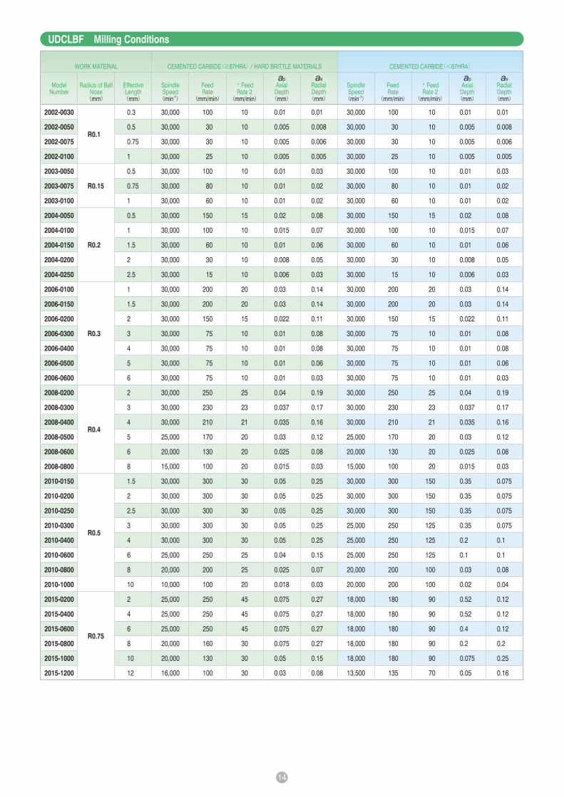
UDCBF Milling Conditions
Note:
・This application requires a high cutting force. A machine with poor rigidity and high vibration is not recommended.
・Allow sufficient machine and spindle warm-up time for stability and to remove any expansion of the main spindle before running the program.
・Tool setting length should achieve the least possible overhang.
・Avoid contact with the coated area of the shank. This will prevent tip vibration and tool jamming in the collet / holder.
・Run-out and vibration should be checked dynamically at the tool point while mounted in the machine and both should achieve the lowest level possible.
・Use an inclined or helical approach (Recommended inclination angle: <5 degree).
・Decrease both spindle speed and feed rate proportionally.
・Air blow is highly recommended for longer tool life. Both oil mist and oil coolant are alternatives.
・Recommend water soluble coolant for Hard Brittle (Non-Metallic) Materials.
・When milling some work pieces, heavier chips may be created. To evacuate these chips it is important to accurately position the coolant nozzle on the milling part.
・Remove chips to prevent heat generation and ignition during milling process.
・Protective gear, such as safety glasses and face guards are required when milling.
・Chips / dust generated while milling can have adverse affects on the machine parts if they are not properly evacuated. Take steps to assure proper evacuation.
These milling parameters are based on VF-20, VM-40, VC-70, VU-70 (CIS standard) for Cemented Carbide, and Alumina for Hard Brittle Materials. These are for reference only.
Tool life may differ depending on the type of Cemented Carbide / Hard Brittle Materials.
For best result, fine parameter adjustments may be required, depending on the materials of Cemented Carbide / Hard Brittle Materials; milling shape and strategy; machine rigidity
and spindle capability.
* Feed Rate2: Feed Rate of Approach and *Connection links.
*Changing from one engagement point to the next.
ap:Axial Depth(mm)ae:Radial Depth(mm)
WORK MATERIAL CEMENTED CARBIDE(≧87HRA) HARD BRITTLE MATERIALS CEMENTED CARBIDE(<87HRA)
Model
Number
Radius of
Ball Nose
(mm)
Length
of Cut
(mm)
Spindle
Speed(min-1)
Feed
Rate(mm/min)
* Feed
Rate 2(mm/min)
ap
Axial
Depth(mm)
ae
Radial
Depth(mm)
Spindle
Speed(min-1)
Feed
Rate(mm/min)
* Feed
Rate 2(mm/min)
ap
Axial
Depth(mm)
ae
Radial
Depth(mm)
2002-0014 R0.1 0.14 30,000 100 10 0.01 0.01 30,000 100 10 0.01 0.01
2003-0021 R0.15 0.21 30,000 125 13 0.015 0.03 30,000 125 13 0.015 0.03
2004-0028 R0.2 0.28 30,000 150 15 0.02 0.08 30,000 150 15 0.02 0.08
2005-0035 R0.25 0.35 30,000 175 18 0.025 0.11 30,000 175 18 0.025 0.11
2006-0042 R0.3 0.42 30,000 200 20 0.03 0.14 30,000 200 20 0.03 0.14
2007-0049 R0.35 0.49 30,000 225 23 0.035 0.17 30,000 225 23 0.035 0.17
2008-0056 R0.4 0.56 30,000 250 25 0.04 0.19 30,000 250 25 0.04 0.19
2009-0063 R0.45 0.63 30,000 275 28 0.045 0.22 30,000 275 28 0.045 0.22
2010-0070 R0.5 0.7 30,000 300 30 0.05 0.25 30,000 300 150 0.35 0.075
2012-0084 R0.6 0.84 27,500 275 36 0.06 0.26 25,000 250 125 0.42 0.09
2015-0105 R0.75 1.05 25,000 250 45 0.075 0.27 19,000 190 95 0.525 0.12
2020-0140 R1 1.4 20,000 200 60 0.1 0.3 12,500 125 60 0.7 0.15
2030-0210 R1.5 2.1 20,000 200 100 0.15 0.3 9,000 280 140 0.38 0.15
2040-0280 R2 2.8 18,000 180 90 0.175 0.32 7,200 280 140 0.5 0.2
2050-0350 R2.5 3.5 16,000 160 80 0.225 0.31 6,000 330 170 0.6 0.25
2060-0420 R3 4.2 15,000 150 75 0.3 0.3 5,500 280 140 0.65 0.28

12
UDCLBFSize ~
Long Neck Ball type End Mills for milling Cemented Carbide and Hard Brittle (Non-Metallic) Materials. Upgraded version of UDCLB.
New Diamond coating and tool geometry increase material removal volume.
Chip pocket designed on tool tip improves the surface finishing quality.
Special cutting edge treatment helps to avoid the edge chipping & level gap.
Recommended to use on semi-roughing & finishing process.
Fe
atu
res
The shank taper angle shown is not an exact value and to avoid
contact with the workpiece, we recommend the user controls the
precise value of this angle. Shank taper angle should not make
contact with the work piece.
Total 61 models Unit(mm)
ModelNumber
Radius ofBall Nose
R
EffectiveLength
1
Lengthof Cut
NeckDiameter
Ød1
Shank TaperAngle
Bta
OverallLength
L
ShankDiameter
Ød
Price
¥
Effective Length byInclined Angles
30‘ 1° 1° 30‘ 2° 3°
UDCLBF 2002-0030
R0.1
0.3
0.14 0.18 16°
50 4 47,500 0.30 0.31 0.32 0.32 0.34
UDCLBF 2002-0050 0.5 50 4 47,500 0.51 0.52 0.54 0.55 0.59
UDCLBF 2002-0075 0.75 50 4 47,500 0.77 0.79 0.81 0.84 0.89
UDCLBF 2002-0100 1 50 4 47,500 1.02 1.05 1.09 1.12 1.20
* UDCLBF 2003-0050
R0.15
0.5
0.21 0.28 16°
50 4 47,500 0.51 0.52 0.53 0.55 0.58
* UDCLBF 2003-0075 0.75 50 4 47,500 0.76 0.78 0.81 0.83 0.88
* UDCLBF 2003-0100 1 50 4 47,500 1.02 1.05 1.08 1.11 1.19
UDCLBF 2004-0050
R0.2
0.5
0.28 0.36 16°
50 4 43,300 0.54 0.55 0.56 0.58 0.61
UDCLBF 2004-0100 1 50 4 43,300 1.06 1.08 1.12 1.15 1.22
UDCLBF 2004-0150 1.5 50 4 43,300 1.57 1.62 1.67 1.72 1.83
UDCLBF 2004-0200 2 50 4 43,300 2.09 2.15 2.22 2.29 2.44
* UDCLBF 2004-0250 2.5 50 4 43,300 2.60 2.68 2.77 2.86 3.06
UDCLBF 2006-0100
R0.3
1
0.42 0.56 16°
50 4 38,900 1.05 1.08 1.11 1.13 1.20
UDCLBF 2006-0150 1.5 50 4 38,900 1.57 1.61 1.66 1.70 1.81
UDCLBF 2006-0200 2 50 4 38,900 2.08 2.14 2.21 2.27 2.42
UDCLBF 2006-0300 3 50 4 38,900 3.12 3.21 3.31 3.41 3.65
UDCLBF 2006-0400 4 50 4 38,900 4.15 4.27 4.41 4.55 4.87
UDCLBF 2006-0500 5 50 4 38,900 5.18 5.34 5.51 5.69 6.09
UDCLBF 2006-0600 6 50 4 38,900 6.21 6.40 6.61 6.83 7.32
Material Applications(☆ Highly Recommended ◎ Recommended ○ Suggested)Work Material
CARBONSTEELS
S45CS55C
ALLOYSTEELS
SK SCMSUS
PREHARDENEDSTEELSNAKHPM
HARDENED STEELS CAST IRON ALUMINUMALLOYS
GRAPHITE COPPER PLASTICS GLASSFILLED
PLASTICS
TITANIUMALLOYS
HEATRESISTANT
ALLOYS
CEMENTEDCARBIDE
HARD BRITTLE(NON-METALLIC)
MATERIALS~ 55HRC ~ 60HRC ~ 70HRC
○ ☆ ◎ *
* Hard Brittle (Non-Metallic) Materials: Ceramics (Alumina, Zirconia, etc.), Glasses and etc.
Diameter and Ball R accuracy measurements are printed on
the label to support High Precision milling.
2Flutes High-grade Long Neck Ball End Mills for Cemented Carbide and Hard Brittle Materials
SAMPLESAMPLE
Label Sample
Patented in JapanAdditional 4 Models
* Additional model

13
2 Flutes High-grade Long Neck Ball End Mills for Cemented Carbide and Hard Brittle Materials
ModelNumber
Radius ofBall Nose
R
EffectiveLength
1
Lengthof Cut
NeckDiameter
Ød1
Shank TaperAngle
Bta
OverallLength
L
ShankDiameter
Ød
Price
¥
Effective Length byInclined Angles
30‘ 1° 1° 30‘ 2° 3°
UDCLBF 2008-0200
R0.4
2
0.56 0.76 16°
50 4 38,900 2.08 2.14 2.20 2.26 2.40
UDCLBF 2008-0300 3 50 4 38,900 3.11 3.20 3.30 3.40 3.62
UDCLBF 2008-0400 4 50 4 38,900 4.14 4.27 4.40 4.54 4.85
UDCLBF 2008-0500 5 50 4 38,900 5.18 5.33 5.50 5.67 6.07
UDCLBF 2008-0600 6 50 4 38,900 6.21 6.40 6.60 6.81 7.29
UDCLBF 2008-0800 8 50 4 38,900 8.27 8.53 8.80 9.09 9.74
UDCLBF 2010-0150
R0.5
1.5
0.7 0.96 16°
50 4 38,900 1.56 1.60 1.64 1.68 1.77
UDCLBF 2010-0200 2 50 4 38,900 2.08 2.13 2.19 2.25 2.38
UDCLBF 2010-0250 2.5 50 4 38,900 2.59 2.66 2.74 2.81 2.99
UDCLBF 2010-0300 3 50 4 38,900 3.11 3.20 3.29 3.38 3.60
UDCLBF 2010-0400 4 50 4 38,900 4.14 4.26 4.39 4.52 4.83
UDCLBF 2010-0600 6 50 4 38,900 6.20 6.39 6.59 6.80 7.27
UDCLBF 2010-0800 8 50 4 38,900 8.27 8.52 8.79 9.08 9.72
UDCLBF 2010-1000 10 50 4 38,900 10.33 10.65 10.99 11.35 12.17
UDCLBF 2015-0200
R0.75
2
1.05 1.4 16°
50 4 38,900 2.11 2.15 2.20 2.25 2.37
UDCLBF 2015-0400 4 50 4 38,900 4.17 4.28 4.40 4.53 4.81
UDCLBF 2015-0600 6 50 4 38,900 6.23 6.41 6.60 6.81 7.26
UDCLBF 2015-0800 8 50 4 38,900 8.29 8.54 8.80 9.08 9.71
UDCLBF 2015-1000 10 50 4 38,900 10.36 10.67 11.00 11.36 12.16
UDCLBF 2015-1200 12 50 4 38,900 12.42 12.80 13.20 13.64 14.60
UDCLBF 2020-0300
R1
3
1.4 1.9 16°
50 4 38,900 3.20 3.27 3.35 3.43 3.62
UDCLBF 2020-0400 4 50 4 38,900 4.23 4.34 4.45 4.57 4.84
UDCLBF 2020-0600 6 50 4 38,900 6.30 6.47 6.65 6.85 7.29
UDCLBF 2020-0800 8 50 4 38,900 8.36 8.60 8.85 9.13 9.74
UDCLBF 2020-1000 10 50 4 38,900 10.42 10.73 11.06 11.41 12.19
UDCLBF 2020-1200 12 50 4 38,900 12.48 12.86 13.26 13.68 14.63
UDCLBF 2020-1400 14 50 4 38,900 14.55 14.99 15.46 15.96 17.08
UDCLBF 2020-1600 16 50 4 38,900 16.61 17.12 17.66 18.24 19.53
UDCLBF 2020-1800 18 60 4 38,900 18.67 19.25 19.86 20.52
No Interference
UDCLBF 2020-2000 20 60 4 38,900 20.74 21.38 22.06 22.79
No Interference
UDCLBF 2030-0600
R1.5
6
2.1 2.9 16°
60 6 42,800 6.28 6.44 6.60 6.78 7.18
UDCLBF 2030-0800 8 60 6 42,800 8.34 8.57 8.80 9.06 9.63
UDCLBF 2030-1000 10 60 6 42,800 10.41 10.70 11.01 11.34 12.08
UDCLBF 2030-1200 12 60 6 42,800 12.47 12.83 13.21 13.61 14.52
UDCLBF 2030-1400 14 60 6 42,800 14.53 14.96 15.41 15.89 16.97
UDCLBF 2040-0800
R2
8
2.8 3.9 16°
60 6 42,800 8.33 8.53 8.76 8.99 9.52
UDCLBF 2040-1000 10 60 6 42,800 10.39 10.66 10.96 11.27 11.97
UDCLBF 2040-1500 15 60 6 42,800 15.55 15.99 16.46 16.96 18.09
UDCLBF 2050-1000R2.5
103.5 4.8 16°
60 6 42,800 10.55 10.82 11.10 11.40 12.07
UDCLBF 2050-1500 15 60 6 42,800 15.71 16.14 16.60 17.09
No Interference
UDCLBF 2060-1000R3
104.2 5.7 !
60 6 42,800
No Interference
No Interference
No Interference
No Interference
No Interference
UDCLBF 2060-1500 15 60 6 42,800
No Interference
No Interference
No Interference
No Interference
No Interference
14
UDCLBF Milling Conditions
WORK MATERIAL CEMENTED CARBIDE(≧87HRA) HARD BRITTLE MATERIALS CEMENTED CARBIDE(<87HRA)
ModelNumber
Radius of Ball Nose(mm)
Effective Length(mm)
Spindle Speed(min-1)
Feed Rate
(mm/min)
* Feed Rate 2
(mm/min)
ap
Axial Depth(mm)
ae
Radial Depth(mm)
Spindle Speed(min-1)
Feed Rate
(mm/min)
* Feed Rate 2
(mm/min)
ap
Axial Depth(mm)
ae
Radial Depth(mm)
2002-0030
R0.1
0.3 30,000 100 10 0.01 0.01 30,000 100 10 0.01 0.01
2002-0050 0.5 30,000 30 10 0.005 0.008 30,000 30 10 0.005 0.008
2002-0075 0.75 30,000 30 10 0.005 0.006 30,000 30 10 0.005 0.006
2002-0100 1 30,000 25 10 0.005 0.005 30,000 25 10 0.005 0.005
2003-0050
R0.15
0.5 30,000 100 10 0.01 0.03 30,000 100 10 0.01 0.03
2003-0075 0.75 30,000 80 10 0.01 0.02 30,000 80 10 0.01 0.02
2003-0100 1 30,000 60 10 0.01 0.02 30,000 60 10 0.01 0.02
2004-0050
R0.2
0.5 30,000 150 15 0.02 0.08 30,000 150 15 0.02 0.08
2004-0100 1 30,000 100 10 0.015 0.07 30,000 100 10 0.015 0.07
2004-0150 1.5 30,000 60 10 0.01 0.06 30,000 60 10 0.01 0.06
2004-0200 2 30,000 30 10 0.008 0.05 30,000 30 10 0.008 0.05
2004-0250 2.5 30,000 15 10 0.006 0.03 30,000 15 10 0.006 0.03
2006-0100
R0.3
1 30,000 200 20 0.03 0.14 30,000 200 20 0.03 0.14
2006-0150 1.5 30,000 200 20 0.03 0.14 30,000 200 20 0.03 0.14
2006-0200 2 30,000 150 15 0.022 0.11 30,000 150 15 0.022 0.11
2006-0300 3 30,000 75 10 0.01 0.08 30,000 75 10 0.01 0.08
2006-0400 4 30,000 75 10 0.01 0.08 30,000 75 10 0.01 0.08
2006-0500 5 30,000 75 10 0.01 0.06 30,000 75 10 0.01 0.06
2006-0600 6 30,000 75 10 0.01 0.03 30,000 75 10 0.01 0.03
2008-0200
R0.4
2 30,000 250 25 0.04 0.19 30,000 250 25 0.04 0.19
2008-0300 3 30,000 230 23 0.037 0.17 30,000 230 23 0.037 0.17
2008-0400 4 30,000 210 21 0.035 0.16 30,000 210 21 0.035 0.16
2008-0500 5 25,000 170 20 0.03 0.12 25,000 170 20 0.03 0.12
2008-0600 6 20,000 130 20 0.025 0.08 20,000 130 20 0.025 0.08
2008-0800 8 15,000 100 20 0.015 0.03 15,000 100 20 0.015 0.03
2010-0150
R0.5
1.5 30,000 300 30 0.05 0.25 30,000 300 150 0.35 0.075
2010-0200 2 30,000 300 30 0.05 0.25 30,000 300 150 0.35 0.075
2010-0250 2.5 30,000 300 30 0.05 0.25 30,000 300 150 0.35 0.075
2010-0300 3 30,000 300 30 0.05 0.25 25,000 250 125 0.35 0.075
2010-0400 4 30,000 300 30 0.05 0.25 25,000 250 125 0.2 0.1
2010-0600 6 25,000 250 25 0.04 0.15 25,000 250 125 0.1 0.1
2010-0800 8 20,000 200 25 0.025 0.07 20,000 200 100 0.03 0.08
2010-1000 10 10,000 100 20 0.018 0.03 20,000 200 100 0.02 0.04
2015-0200
R0.75
2 25,000 250 45 0.075 0.27 18,000 180 90 0.52 0.12
2015-0400 4 25,000 250 45 0.075 0.27 18,000 180 90 0.52 0.12
2015-0600 6 25,000 250 45 0.075 0.27 18,000 180 90 0.4 0.12
2015-0800 8 20,000 160 30 0.075 0.27 18,000 180 90 0.2 0.2
2015-1000 10 20,000 130 30 0.05 0.15 18,000 180 90 0.075 0.25
2015-1200 12 16,000 100 30 0.03 0.08 13,500 135 70 0.05 0.16
15
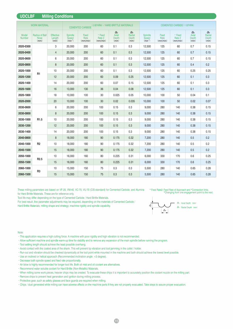
UDCLBF Milling Conditions
Note:
・This application requires a high cutting force. A machine with poor rigidity and high vibration is not recommended.
・Allow sufficient machine and spindle warm-up time for stability and to remove any expansion of the main spindle before running the program.
・Tool setting length should achieve the least possible overhang.
・Avoid contact with the coated area of the shank. This will prevent tip vibration and tool jamming in the collet / holder.
・Run-out and vibration should be checked dynamically at the tool point while mounted in the machine and both should achieve the lowest level possible.
・Use an inclined or helical approach (Recommended inclination angle: <5 degree).
・Decrease both spindle speed and feed rate proportionally.
・Air blow is highly recommended for longer tool life. Both oil mist and oil coolant are alternatives.
・Recommend water soluble coolant for Hard Brittle (Non-Metallic) Materials.
・When milling some work pieces, heavier chips may be created. To evacuate these chips it is important to accurately position the coolant nozzle on the milling part.
・Remove chips to prevent heat generation and ignition during milling process.
・Protective gear, such as safety glasses and face guards are required when milling.
・Chips / dust generated while milling can have adverse affects on the machine parts if they are not properly evacuated. Take steps to assure proper evacuation.
These milling parameters are based on VF-20, VM-40, VC-70, VU-70 (CIS standard) for Cemented Carbide, and Alumina
for Hard Brittle Materials. These are for reference only.
Tool life may differ depending on the type of Cemented Carbide / Hard Brittle Materials.
For best result, fine parameter adjustments may be required, depending on the materials of Cemented Carbide /
Hard Brittle Materials; milling shape and strategy; machine rigidity and spindle capability.
WORK MATERIALCEMENTED CARBIDE
(≧87HRA) HARD BRITTLE MATERIALS CEMENTED CARBIDE(<87HRA)
ModelNumber
Radius of Ball Nose(mm)
Effective Length(mm)
Spindle Speed(min-1)
Feed Rate
(mm/min)
* Feed Rate 2
(mm/min)
ap
Axial Depth(mm)
ae
Radial Depth(mm)
Spindle Speed(min-1)
Feed Rate
(mm/min)
* Feed Rate 2
(mm/min)
ap
Axial Depth(mm)
ae
Radial Depth(mm)
2020-0300
R1
3 20,000 200 60 0.1 0.3 12,500 125 60 0.7 0.15
2020-0400 4 20,000 200 60 0.1 0.3 12,500 125 60 0.7 0.15
2020-0600 6 20,000 200 60 0.1 0.3 12,500 125 60 0.7 0.15
2020-0800 8 20,000 200 60 0.1 0.3 12,500 125 60 0.4 0.2
2020-1000 10 20,000 200 60 0.1 0.3 12,500 125 60 0.25 0.25
2020-1200 12 20,000 200 60 0.09 0.25 12,500 125 60 0.1 0.3
2020-1400 14 20,000 200 60 0.07 0.15 12,500 125 60 0.1 0.3
2020-1600 16 13,000 130 36 0.04 0.08 12,500 125 60 0.1 0.3
2020-1800 18 10,000 100 30 0.025 0.05 10,000 100 50 0.04 0.1
2020-2000 20 10,000 100 30 0.02 0.035 10,000 100 50 0.02 0.07
2030-0600
R1.5
6 20,000 200 100 0.15 0.3 9,000 280 140 0.38 0.15
2030-0800 8 20,000 200 100 0.15 0.3 9,000 280 140 0.38 0.15
2030-1000 10 20,000 200 100 0.15 0.3 9,000 280 140 0.38 0.15
2030-1200 12 20,000 200 100 0.15 0.3 9,000 280 140 0.38 0.15
2030-1400 14 20,000 200 100 0.15 0.3 9,000 280 140 0.38 0.15
2040-0800
R2
8 18,000 180 90 0.175 0.32 7,200 280 140 0.5 0.2
2040-1000 10 18,000 180 90 0.175 0.32 7,200 280 140 0.5 0.2
2040-1500 15 18,000 180 90 0.175 0.32 7,200 280 140 0.5 0.2
2050-1000R2.5
10 16,000 160 80 0.225 0.31 6,000 330 170 0.6 0.25
2050-1500 15 16,000 160 80 0.225 0.31 6,000 330 170 0.6 0.25
2060-1000R3
10 15,000 150 75 0.3 0.3 5,500 280 140 0.65 0.28
2060-1500 15 15,000 150 75 0.3 0.3 5,500 280 140 0.65 0.28
.sknil noitcennoC* dna hcaorppA fo etaR deeF :2etaR dee* F *Changing from one engagement point to the next.
ap:Axial Depth(mm)
ae:Radial Depth(mm)

16
UDCLRSFSize ~
Total 52 models Unit(mm)
ModelNumber
OutsideDiameter
ØD
ConerRadius
CR
EffectiveLength
1
Lengthof Cut
NeckDiameter
Ød1
Shank TaperAngle
Bta
OverallLength
L
ShankDiameter
Ød
Price
¥
Effective Length byInclined Angles
30‘ 1° 1° 30‘ 2° 3°
UDCLRSF 2003-0030060.3
R0.03 0.60.15 0.28 16°
50 4 54,600 0.61 0.63 0.65 0.67 0.72
UDCLRSF 2003-005006 R0.05 0.6 50 4 54,600 0.61 0.63 0.65 0.67 0.72
UDCLRSF 2005-003005
0.5
R0.03
0.5
0.25 0.46 16°
50 4 52,000 0.55 0.56 0.58 0.60 0.64
UDCLRSF 2005-003010 1 50 4 52,000 1.06 1.10 1.13 1.17 1.25
* UDCLRSF 2005-003015 1.5 50 4 52,000 1.58 1.63 1.68 1.74 1.87
UDCLRSF 2005-005005
R0.05
0.5 50 4 52,000 0.55 0.56 0.58 0.60 0.64
UDCLRSF 2005-005010 1 50 4 52,000 1.06 1.09 1.13 1.17 1.25
* UDCLRSF 2005-005015 1.5 50 4 52,000 1.58 1.63 1.68 1.74 1.86
UDCLRSF 2008-003008
0.8
R0.03
0.8
0.4 0.76 16°
50 4 46,700 0.86 0.88 0.91 0.94 1.01
UDCLRSF 2008-003016 1.6 50 4 46,700 1.68 1.73 1.79 1.85 1.99
* UDCLRSF 2008-003024 2.4 50 4 46,700 2.51 2.59 2.67 2.76 2.97
UDCLRSF 2008-005008
R0.05
0.8 50 4 46,700 0.85 0.88 0.91 0.94 1.01
UDCLRSF 2008-005016 1.6 50 4 46,700 1.68 1.73 1.79 1.85 1.98
* UDCLRSF 2008-005024 2.4 50 4 46,700 2.50 2.58 2.67 2.76 2.96
UDCLRSF 2008-010008
R0.1
0.8 50 4 46,700 0.85 0.88 0.90 0.93 0.99
UDCLRSF 2008-010016 1.6 50 4 46,700 1.68 1.73 1.78 1.84 1.97
* UDCLRSF 2008-010024 2.4 50 4 46,700 2.50 2.58 2.66 2.75 2.95
Material Applications(☆ Highly Recommended ◎ Recommended ○ Suggested)Work Material
CARBONSTEELS
S45CS55C
ALLOYSTEELS
SK SCMSUS
PREHARDENEDSTEELSNAKHPM
HARDENED STEELS CAST IRON ALUMINUMALLOYS
GRAPHITE COPPER PLASTICS GLASSFILLED
PLASTICS
TITANIUMALLOYS
HEATRESISTANT
ALLOYS
CEMENTEDCARBIDE
HARD BRITTLE(NON-METALLIC)
MATERIALS~ 55HRC ~ 60HRC ~ 70HRC
○ ☆ ◎ *
* Hard Brittle (Non-Metallic) Materials: Ceramics (Alumina, Zirconia, etc.), Glasses and etc.
2Flutes High-grade Long Neck Radius End Mills for Cemented Carbide and Hard Brittle Materials
Long Neck Radius End Mills for milling Cemented Carbide & Hard Brittle (Non-Metallic) Materials.
Upgraded version of UDCLRS.
Achieve remarkable cutting depth and longer tool life.
Special cutting edge treatment helps to avoid the edge chipping & level gap on the work piece.
Recommended to use on semi-roughing & finishing process.
Fe
atu
res
The shank taper angle shown is not an exact value and to avoid
contact with the workpiece, we recommend the user controls the
precise value of this angle. Shank taper angle should not make
contact with the work piece.
Diameter and Corner R accuracy measurements are printed on
the label to support High Precision milling.
SAMPLESAMPLE
Label Sample
Patented in JapanAdditional 22 Models
* Additional model

17
2Flutes High-grade Long Neck Radius End Mills for Cemented Carbide and Hard Brittle Materials
ModelNumber
OutsideDiameter
ØD
ConerRadius
CR
EffectiveLength
1
Lengthof Cut
NeckDiameter
Ød1
Shank TaperAngle
Bta
OverallLength
L
ShankDiameter
Ød
Price
¥
Effective Length byInclined Angles
30‘ 1° 1° 30‘ 2° 3°
UDCLRSF 2010-003010
1
R0.03
1
0.5 0.96 16°
50 4 46,700 1.06 1.10 1.13 1.17 1.25
UDCLRSF 2010-003020 2 50 4 46,700 2.09 2.16 2.23 2.31 2.48
* UDCLRSF 2010-003040 4 50 4 46,700 4.16 4.29 4.43 4.59 4.93
* UDCLRSF 2010-003060 6 50 4 46,700 6.22 6.42 6.63 6.86 7.37
UDCLRSF 2010-005010
R0.05
1 50 4 46,700 1.06 1.09 1.13 1.17 1.25
UDCLRSF 2010-005020 2 50 4 46,700 2.09 2.16 2.23 2.31 2.47
* UDCLRSF 2010-005040 4 50 4 46,700 4.15 4.29 4.43 4.58 4.92
* UDCLRSF 2010-005060 6 50 4 46,700 6.22 6.42 6.63 6.86 7.37
UDCLRSF 2010-010010
R0.1
1 50 4 46,700 1.06 1.09 1.12 1.16 1.24
UDCLRSF 2010-010020 2 50 4 46,700 2.09 2.16 2.22 2.30 2.46
* UDCLRSF 2010-010040 4 50 4 46,700 4.15 4.28 4.43 4.58 4.91
* UDCLRSF 2010-010060 6 50 4 46,700 6.22 6.41 6.63 6.85 7.36
UDCLRSF 2015-003015
1.5
R0.03 1.5
0.75 1.44 16°
50 4 46,700 1.61 1.66 1.72 1.78 1.91
UDCLRSF 2015-003030 3 50 4 46,700 3.16 3.26 3.37 3.49 3.74
UDCLRSF 2015-005015R0.05
1.5 50 4 46,700 1.61 1.66 1.72 1.78 1.90
UDCLRSF 2015-005030 3 50 4 46,700 3.16 3.26 3.37 3.48 3.74
UDCLRSF 2015-010015
R0.1
1.5 50 4 46,700 1.61 1.66 1.71 1.77 1.89
UDCLRSF 2015-010030 3 50 4 46,700 3.16 3.26 3.36 3.48 3.73
* UDCLRSF 2015-010040 4 50 4 46,700 4.19 4.32 4.46 4.62 4.95
* UDCLRSF 2015-010060 6 50 4 46,700 6.25 6.45 6.66 6.89 7.40
UDCLRSF 2020-003020
2
R0.03
2
1 1.9 16°
50 4 46,700 2.20 2.27 2.35 2.43 2.61
UDCLRSF 2020-003040 4 50 4 46,700 4.26 4.40 4.55 4.70 5.05
* UDCLRSF 2020-003060 6 50 4 46,700 6.33 6.53 6.75 6.98 7.50
* UDCLRSF 2020-003080 8 50 4 46,700 8.39 8.66 8.95 9.26 9.95
* UDCLRSF 2020-003100 10 50 4 46,700 10.45 10.79 11.15 11.54 12.40
UDCLRSF 2020-005020
R0.05
2 50 4 46,700 2.20 2.27 2.34 2.42 2.60
UDCLRSF 2020-005040 4 50 4 46,700 4.26 4.40 4.55 4.70 5.05
* UDCLRSF 2020-005060 6 50 4 46,700 6.33 6.53 6.75 6.98 7.50
* UDCLRSF 2020-005080 8 50 4 46,700 8.39 8.66 8.95 9.26 9.94
* UDCLRSF 2020-005100 10 50 4 46,700 10.45 10.79 11.15 11.53 12.39
UDCLRSF 2020-010020
R0.1
2 50 4 46,700 2.20 2.27 2.34 2.42 2.59
UDCLRSF 2020-010040 4 50 4 46,700 4.26 4.40 4.54 4.69 5.04
* UDCLRSF 2020-010060 6 50 4 46,700 6.32 6.53 6.74 6.97 7.49
* UDCLRSF 2020-010080 8 50 4 46,700 8.39 8.66 8.94 9.25 9.93
* UDCLRSF 2020-010100 10 50 4 46,700 10.45 10.79 11.14 11.53 12.38
* Additional model

18
WORK MATERIAL
CEMENTED CARBIDE(≧87HRA) HARD BRITTLE MATERIALS
Model Number
Spindle Speed (min-1)
Z-Level Milling Flat Milling Side Milling Slotting
Feed Rate (mm/min)
* Feed Rate 2 (mm/min)
ap
Axial Depth (mm)
ae
Radial Depth (mm)
Feed Rate (mm/min)
ap
Axial Depth (mm)
ae
Radial Depth (mm)
Feed Rate (mm/min)
ap
Axial Depth (mm)
ae
Radial Depth (mm)
Feed Rate (mm/min)
ap
Axial Depth (mm)
2003-003006 30,000 220 50 0.015 0.200 220 0.015 0.200 110 0.075 0.006 110 0.015
2003-005006 30,000 220 50 0.020 0.200 220 0.020 0.200 110 0.075 0.006 110 0.020
2005-003005 30,000 190 90 0.020 0.400 190 0.020 0.400 180 0.250 0.010 190 0.020
2005-003010 30,000 190 90 0.020 0.400 190 0.020 0.400 180 0.125 0.010 190 0.020
2005-003015 30,000 140 65 0.015 0.300 140 0.015 0.300 130 0.125 0.007 140 0.015
2005-005005 30,000 190 125 0.020 0.400 190 0.020 0.400 180 0.250 0.010 190 0.020
2005-005010 30,000 190 125 0.020 0.400 190 0.020 0.400 180 0.125 0.010 190 0.020
2005-005015 30,000 140 65 0.015 0.300 140 0.015 0.300 130 0.125 0.007 140 0.015
2008-003008 30,000 190 90 0.020 0.600 190 0.020 0.600 300 0.400 0.016 190 0.020
2008-003016 30,000 190 90 0.020 0.600 190 0.020 0.600 300 0.200 0.010 190 0.020
2008-003024 30,000 175 80 0.018 0.500 175 0.018 0.500 275 0.200 0.007 175 0.018
2008-005008 30,000 190 150 0.025 0.600 190 0.025 0.600 300 0.400 0.016 190 0.025
2008-005016 30,000 190 150 0.025 0.600 190 0.025 0.600 300 0.200 0.010 190 0.025
2008-005024 30,000 175 80 0.023 0.500 175 0.023 0.500 275 0.200 0.007 175 0.023
2008-010008 30,000 190 150 0.030 0.600 190 0.030 0.600 300 0.400 0.016 190 0.030
2008-010016 30,000 190 150 0.030 0.600 190 0.030 0.600 300 0.200 0.010 190 0.030
2008-010024 30,000 175 80 0.028 0.500 175 0.028 0.500 275 0.200 0.007 175 0.028
2010-003010 30,000 190 90 0.020 0.800 190 0.020 0.800 375 0.500 0.020 190 0.020
2010-003020 30,000 190 90 0.020 0.800 190 0.020 0.800 375 0.250 0.010 190 0.020
2010-003040 30,000 190 90 0.016 0.600 190 0.016 0.600 375 0.250 0.005 190 0.016
2010-003060 25,000 155 75 0.010 0.500 155 0.010 0.500 300 0.250 0.005 155 0.010
2010-005010 30,000 190 185 0.025 0.800 190 0.025 0.800 375 0.500 0.020 190 0.025
2010-005020 30,000 190 185 0.025 0.800 190 0.025 0.800 375 0.250 0.010 190 0.025
2010-005040 30,000 190 185 0.020 0.600 190 0.020 0.600 375 0.250 0.005 190 0.020
2010-005060 25,000 155 150 0.012 0.500 155 0.012 0.500 300 0.250 0.005 155 0.012
2010-010010 30,000 190 185 0.030 0.800 190 0.030 0.800 375 0.500 0.020 190 0.030
2010-010020 30,000 190 185 0.030 0.800 190 0.030 0.800 375 0.250 0.010 190 0.030
2010-010040 30,000 190 185 0.025 0.600 190 0.025 0.600 375 0.250 0.005 190 0.025
2010-010060 25,000 155 150 0.015 0.500 155 0.015 0.500 300 0.250 0.005 155 0.015
2015-003015 25,000 190 90 0.030 1.300 190 0.030 1.300 375 0.750 0.020 190 0.030
2015-003030 25,000 190 90 0.030 1.300 190 0.030 1.300 375 0.375 0.010 190 0.030
2015-005015 25,000 190 125 0.040 1.300 190 0.040 1.300 375 0.750 0.020 190 0.040
2015-005030 25,000 190 125 0.040 1.300 190 0.040 1.300 375 0.375 0.010 190 0.040
2015-010015 25,000 190 150 0.045 1.300 190 0.045 1.300 375 0.750 0.020 190 0.045
2015-010030 25,000 190 150 0.045 1.300 190 0.045 1.300 375 0.375 0.010 190 0.045
2015-010040 25,000 190 150 0.043 1.200 190 0.043 1.200 350 0.375 0.008 190 0.043
2015-010060 25,000 190 150 0.040 1.000 190 0.040 1.000 350 0.375 0.005 190 0.040
UDCLRSF Milling Conditions Refer to page 22 for UDCLRSF note.

19
WORK MATERIAL
CEMENTED CARBIDE(<87HRA)
Model Number
Spindle Speed (min-1)
Z-Level Milling Flat Milling Side Milling Slotting
Feed Rate (mm/min)
* Feed Rate 2 (mm/min)
ap
Axial Depth (mm)
ae
Radial Depth (mm)
Feed Rate (mm/min)
ap
Axial Depth (mm)
ae
Radial Depth (mm)
Feed Rate (mm/min)
ap
Axial Depth (mm)
ae
Radial Depth (mm)
Feed Rate (mm/min)
ap
Axial Depth (mm)
2003-003006 21,000 300 50 0.015 0.200 300 0.015 0.200 200 0.075 0.003 300 0.015
2003-005006 21,000 300 50 0.020 0.200 300 0.020 0.200 200 0.075 0.003 300 0.020
2005-003005 16,000 500 160 0.020 0.400 500 0.020 0.400 800 0.250 0.005 500 0.020
2005-003010 16,000 500 160 0.020 0.400 500 0.020 0.400 400 0.125 0.005 500 0.020
2005-003015 16,000 375 120 0.014 0.300 375 0.014 0.300 300 0.125 0.005 375 0.014
2005-005005 16,000 500 160 0.025 0.400 500 0.025 0.400 800 0.250 0.005 500 0.025
2005-005010 16,000 500 160 0.025 0.400 500 0.025 0.400 400 0.125 0.005 500 0.025
2005-005015 16,000 375 120 0.017 0.300 375 0.017 0.300 300 0.125 0.005 375 0.017
2008-003008 13,000 390 130 0.020 0.600 390 0.020 0.600 1200 0.400 0.008 390 0.020
2008-003016 13,000 390 130 0.020 0.600 390 0.020 0.600 600 0.200 0.008 390 0.020
2008-003024 13,000 350 120 0.014 0.500 350 0.014 0.500 540 0.200 0.006 350 0.014
2008-005008 13,000 390 130 0.025 0.600 390 0.025 0.600 1200 0.400 0.008 390 0.025
2008-005016 13,000 390 130 0.025 0.600 390 0.025 0.600 600 0.200 0.008 390 0.025
2008-005024 13,000 350 120 0.017 0.500 350 0.017 0.500 540 0.200 0.006 350 0.017
2008-010008 13,000 390 130 0.030 0.600 390 0.030 0.600 1200 0.400 0.008 390 0.030
2008-010016 13,000 390 130 0.030 0.600 390 0.030 0.600 600 0.200 0.008 390 0.030
2008-010024 13,000 350 120 0.020 0.500 350 0.020 0.500 540 0.200 0.006 350 0.020
2010-003010 12,000 360 120 0.020 0.800 360 0.020 0.800 1440 0.500 0.010 360 0.020
2010-003020 12,000 360 120 0.020 0.800 360 0.020 0.800 720 0.250 0.010 360 0.020
2010-003040 10,000 300 100 0.012 0.700 300 0.012 0.700 600 0.250 0.008 300 0.012
2010-003060 10,000 300 100 0.008 0.700 300 0.008 0.700 600 0.250 0.006 300 0.008
2010-005010 12,000 360 120 0.025 0.800 360 0.025 0.800 1440 0.500 0.010 360 0.025
2010-005020 12,000 360 120 0.025 0.800 360 0.025 0.800 720 0.250 0.010 360 0.025
2010-005040 10,000 300 100 0.015 0.700 300 0.015 0.700 600 0.250 0.008 300 0.015
2010-005060 10,000 300 100 0.010 0.700 300 0.010 0.700 600 0.250 0.006 300 0.010
2010-010010 12,000 360 120 0.030 0.800 360 0.030 0.800 1440 0.500 0.010 360 0.030
2010-010020 12,000 360 120 0.030 0.800 360 0.030 0.800 720 0.250 0.010 360 0.030
2010-010040 10,000 300 100 0.020 0.700 300 0.020 0.700 600 0.250 0.008 300 0.020
2010-010060 10,000 300 100 0.012 0.700 300 0.012 0.700 600 0.250 0.006 300 0.012
2015-003015 11,000 330 110 0.030 1.300 330 0.030 1.300 1440 0.750 0.010 330 0.030
2015-003030 11,000 330 110 0.030 1.300 330 0.030 1.300 720 0.375 0.010 330 0.030
2015-005015 11,000 330 110 0.040 1.300 330 0.040 1.300 1440 0.750 0.010 330 0.040
2015-005030 11,000 330 110 0.040 1.300 330 0.040 1.300 720 0.375 0.010 330 0.040
2015-010015 11,000 330 110 0.045 1.300 330 0.045 1.300 1440 0.750 0.010 330 0.045
2015-010030 11,000 330 110 0.045 1.300 330 0.045 1.300 720 0.375 0.010 330 0.045
2015-010040 11,000 330 110 0.045 1.100 330 0.045 1.100 720 0.375 0.010 330 0.045
2015-010060 11,000 330 110 0.030 1.100 330 0.030 1.100 720 0.375 0.009 330 0.030
UDCLRSF Milling Conditions Refer to page 22 for UDCLRSF note.

20
WORK MATERIAL
CEMENTED CARBIDE(≧87HRA) HARD BRITTLE MATERIALS
Model Number
Spindle Speed (min-1)
Z-Level Milling Flat Milling Side Milling Slotting
Feed Rate (mm/min)
* Feed Rate 2 (mm/min)
ap
Axial Depth (mm)
ae
Radial Depth (mm)
Feed Rate (mm/min)
ap
Axial Depth (mm)
ae
Radial Depth (mm)
Feed Rate (mm/min)
ap
Axial Depth (mm)
ae
Radial Depth (mm)
Feed Rate (mm/min)
ap
Axial Depth (mm)
2020-003020 20,000 190 90 0.040 1.800 190 0.040 1.800 375 1.000 0.020 190 0.040
2020-003040 20,000 190 90 0.040 1.800 190 0.040 1.800 375 0.500 0.010 190 0.040
2020-003060 20,000 190 90 0.037 1.700 190 0.037 1.700 325 0.500 0.007 190 0.037
2020-003080 20,000 190 90 0.030 1.500 190 0.030 1.500 325 0.500 0.005 190 0.030
2020-003100 20,000 190 90 0.025 1.300 190 0.025 1.300 300 0.500 0.005 190 0.025
2020-005020 20,000 190 90 0.050 1.800 190 0.050 1.800 375 1.000 0.020 190 0.050
2020-005040 20,000 190 90 0.050 1.800 190 0.050 1.800 375 0.500 0.010 190 0.050
2020-005060 20,000 190 90 0.045 1.700 190 0.045 1.700 325 0.500 0.007 190 0.045
2020-005080 20,000 190 90 0.040 1.500 190 0.040 1.500 325 0.500 0.005 190 0.040
2020-005100 20,000 190 90 0.028 1.300 190 0.028 1.300 300 0.500 0.005 190 0.028
2020-010020 20,000 190 125 0.060 1.800 190 0.060 1.800 375 1.000 0.020 190 0.060
2020-010040 20,000 190 125 0.060 1.800 190 0.060 1.800 375 0.500 0.010 190 0.060
2020-010060 20,000 190 125 0.055 1.700 190 0.055 1.700 325 0.500 0.007 190 0.055
2020-010080 20,000 190 125 0.045 1.500 190 0.045 1.500 325 0.500 0.005 190 0.045
2020-010100 20,000 190 125 0.033 1.300 190 0.033 1.300 300 0.500 0.005 190 0.033
UDCLRSF Milling Conditions Refer to page 22 for UDCLRSF note.

21
WORK MATERIAL CEMENTED CARBIDE(<87HRA)
Model Number
Spindle Speed (min-1)
Z-Level Milling Flat Milling Side Milling Slotting
Feed Rate (mm/min)
* Feed Rate 2 (mm/min)
ap
Axial Depth (mm)
ae
Radial Depth (mm)
Feed Rate (mm/min)
ap
Axial Depth (mm)
ae
Radial Depth (mm)
Feed Rate (mm/min)
ap
Axial Depth (mm)
ae
Radial Depth (mm)
Feed Rate (mm/min)
ap
Axial Depth (mm)
2020-003020 10,000 300 100 0.040 1.800 300 0.040 1.800 1440 1.000 0.010 300 0.040
2020-003040 10,000 300 100 0.040 1.800 300 0.040 1.800 1440 1.000 0.010 300 0.040
2020-003060 10,000 300 100 0.036 1.600 300 0.036 1.600 1440 0.500 0.010 300 0.036
2020-003080 10,000 300 100 0.023 1.600 300 0.023 1.600 1440 0.500 0.009 300 0.023
2020-003100 10,000 300 100 0.018 1.600 300 0.018 1.600 1440 0.500 0.009 300 0.018
2020-005020 10,000 300 100 0.050 1.800 300 0.050 1.800 1440 1.000 0.010 300 0.050
2020-005040 10,000 300 100 0.050 1.800 300 0.050 1.800 1440 1.000 0.010 300 0.050
2020-005060 10,000 300 100 0.045 1.600 300 0.045 1.600 1440 0.500 0.010 300 0.045
2020-005080 10,000 300 100 0.028 1.600 300 0.028 1.600 1440 0.500 0.009 300 0.028
2020-005100 10,000 300 100 0.020 1.600 300 0.020 1.600 1440 0.500 0.009 300 0.020
2020-010020 10,000 300 100 0.060 1.800 300 0.060 1.800 1440 1.000 0.010 300 0.060
2020-010040 10,000 300 100 0.060 1.800 300 0.060 1.800 1440 1.000 0.010 300 0.060
2020-010060 10,000 300 100 0.054 1.600 300 0.054 1.600 1440 0.500 0.010 300 0.054
2020-010080 10,000 300 100 0.034 1.600 300 0.034 1.600 1440 0.500 0.009 300 0.034
2020-010100 10,000 300 100 0.023 1.600 300 0.023 1.600 1440 0.500 0.009 300 0.023
Z-Level / Side / Flat Milling
ap:Axial Depth(mm)ap:Radial Depth(mm)
Slotting
ap:Axial Depth(mm)D : Tool Outside Diameter
These milling parameters are based on VF-20, VM-40, VU-70 (CIS standard) and are for reference only.
Tool life may differ depending on the type of Cemented Carbide / Hard Brittle Materials.
For best result, fine parameter adjustments may be required, depending on the materials of Cemented Carbide / Hard Brittle Materials; milling shape and strategy; machine rigidity
and spindle capability.
.sknil noitcennoC* dna hcaorppA fo etaR deeF :2etaR dee *F
*Changing from one engagement point to the next.
UDCLRSF Milling Conditions Refer to page 22 for UDCLRSF note.

Note:
・This application requires a high cutting force. A machine with poor rigidity and high vibration is not recommended.
・Allow sufficient machine and spindle warm-up time for stability and to remove any expansion of the main spindle before running the program.
・Tool setting length should achieve the least possible overhang.
・Avoid contact with the coated area of the shank. This will prevent tip vibration and tool jamming in the collet / holder.
・Run-out and vibration should be checked dynamically at the tool point while mounted in the machine and both should achieve the lowest level possible.
・Does not require to be slowed down in the approach sequence when slotting and side milling.
・Use an inclined or helical approach when Z-level milling (Recommended inclination angle: <1 degree).
・For flat and side milling, set the axial depth (ap) and radial depth (ae) to allow for the uncut material of the corner radius.
・Decrease both spindle speed and feed rate proportionally.
・Air blow is highly recommended for longer tool life. Both oil mist and oil coolant are alternatives.
・Recommend water soluble coolant for Hard Brittle (Non-Metallic) Materials.
・When milling some work pieces, heavier chips may be created. To evacuate these chips it is important to accurately position the coolant nozzle on the milling part.
・Remove chips to prevent heat generation and ignition during milling process.
・Protective gear, such as safety glasses and face guards are required when milling.
・Chips / dust generated while milling can have adverse affects on the machine parts if they are not properly evacuated. Take steps to assure proper evacuation.
UDCLRSF Note

23
Tool UDCLRS 2020-010-020 UDCLRSF 2020-010020
Spindle Speed 20,000 min-1
Feed Rate 375 mm/min 190 mm/min
ap
Axial Depth0.02 mm 0.06 mm
Coolant Nozzle Air Blow
Cycle Time(Per slot) 9 min 4 sec 5 min 36 sec
ToolUDCLRS 2020-003-020UDCLRSF 2020-003020
Spindle Speed 20,000 min-1
Feed Rate 100 mm/min
ap
Axial Depth0.01 mm
ae
Radial Depth0.01 mm
Coolant Oil Mist
Cycle Time 137 min
UDCLRS UDCLRSF
After 4 slots After 5 slots
After 4 slots After 5 slots
Size ::
20 × 20 × 10 mmSlot Size Width 2 × Depth 1.99 mm
UDCLRSF Ø2×CR0.1 VM-40(90HRA)
Cemented Carbide Curve Slotting Milling Example
UDCLRSF Ø2 × CR0.03 × 2 VM-40(90HRA)
Cemented Carbide Bottom Surface Milling Example
Higher efficiency and longer tool life!
Minimizing Edge Chipping
Wor
k M
ater
ial
Rak
e Fa
ceR
elie
f
352
440
UDCLRS UDCLRSF0
2
4
6
8
10
12
14
0
100
200
300
400
500
min
Cyc
le T
ime
Per
Slo
t
mm
3M
ater
ial R
emov
al
Volu
me
Material Removal Volume
Cycle Time Per Slot
Corner Radius Damage More tool life left
0.055
0.027
0.013 0.010
0.000
0.020
0.040
0.060
mm
Max
imum
Edg
e C
hipp
ing
Wid
th
UDCLRS UDCLRSF
EntryEntry Exit Exit
Milling
Dire
ction
Entry Side
10 m
m
Exit SideMilling Direction
Edge Chipping Comparison on Work Material
Edge Chipping Width
Entry Side
Exit Side
UDCLRS UDCLRSF
Edge of work
100 m
Milling Surface
Milling Surface
100 m

24
UDCBSize ~
Ball type End Mills for milling Cemented Carbide and Hard Brittle (Non-Metallic) Materials.
Developed to give improved hardness and durability, new Diamond coating also has outstanding adhesion to the cutting tool.
Achieve remarkable cutting depth with optimum tool geometry.
Leaves a burr and pit free surface finish on semi-roughing & finishing process.
Fe
atu
res
The shank taper angle shown is not an exact value and to avoid
contact with the workpiece, we recommend the user controls the
precise value of this angle. Shank taper angle should not make
contact with the work piece.
Total 14 models Unit(mm)
Model
Number
Radius of
Ball Nose
R
Length
of Cut
Shank Taper
Angle
Bta
Overall
Length
L
Shank
Diameter
Ød
Price
¥
UDCB 2002-0014 R0.1 0.14 16° 50 4 39,160
UDCB 2003-0021 R0.15 0.21 16° 50 4 39,160
UDCB 2004-0028 R0.2 0.28 16° 50 4 35,660
UDCB 2005-0035 R0.25 0.35 16° 50 4 35,660
UDCB 2006-0042 R0.3 0.42 16° 50 4 32,000
UDCB 2007-0049 R0.35 0.49 16° 50 4 32,000
UDCB 2008-0056 R0.4 0.56 16° 50 4 32,000
UDCB 2009-0063 R0.45 0.63 16° 50 4 32,000
UDCB 2010-0070 R0.5 0.7 16° 50 4 32,000
UDCB 2020-0140 R1 1.4 16° 50 4 32,000
UDCB 2030-0210 R1.5 2.1 16° 60 6 35,160
UDCB 2040-0280 R2 2.8 16° 60 6 35,160
UDCB 2050-0350 R2.5 3.5 16° 60 6 35,160
UDCB 2060-0420 R3 4.2 ! 60 6 35,160
Material Applications(☆ Highly Recommended ◎ Recommended ○ Suggested)Work Material
CARBONSTEELS
S45CS55C
ALLOYSTEELS
SK SCMSUS
PREHARDENEDSTEELSNAKHPM
HARDENED STEELS CAST IRON ALUMINUMALLOYS
GRAPHITE COPPER PLASTICS GLASSFILLED
PLASTICS
TITANIUMALLOYS
HEATRESISTANT
ALLOYS
CEMENTEDCARBIDE
HARD BRITTLE(NON-METALLIC)
MATERIALS~ 55HRC ~ 60HRC ~ 70HRC
○*1
☆ ◎*2
* 1 DCB / DCLB series are highly recommended for Glass Filled Plastic milling.
* 2 Hard Brittle (Non-Metallic) Materials: Ceramics (Alumina, Zirconia, etc.), Glasses and etc.
2 Flutes Ball End Mills for Cemented Carbide and Hard Brittle Materials
Diameter and Ball R accuracy measurements are printed on
the label to support High Precision milling.
SAMPLESAMPLE
Label Sample

25
UDCB Milling Conditions
Note:
・This application requires a high cutting force. A machine with poor rigidity and high vibration is not recommended.
・Allow sufficient machine and spindle warm-up time for stability and to remove any expansion of the main spindle before running the program.
・Tool setting length should achieve the least possible overhang.
・Avoid contact with the coated area of the shank. This will prevent tip vibration and tool jamming in the collet / holder.
・Run-out and vibration should be checked dynamically at the tool point while mounted in the machine and both should achieve the lowest level possible.
・Use an inclined or helical approach (Recommended inclination angle: <5 degree).
・Decrease both spindle speed and feed rate proportionally.
・Air blow is highly recommended for longer tool life. Both oil mist and oil coolant are alternatives.
・Recommend water soluble coolant for Hard Brittle (Non-Metallic) Materials.
・When milling some work pieces, heavier chips may be created. To evacuate these chips it is important to accurately position the coolant nozzle on the milling part.
・Remove chips to prevent heat generation and ignition during milling process.
・Protective gear, such as safety glasses and face guards are required when milling.
・Chips / dust generated while milling can have adverse affects on the machine parts if they are not properly evacuated. Take steps to assure proper evacuation.
WORK MATERIAL CEMENTED CARBIDE(≧87HRA) CEMENTED CARBIDE(<87HRA) HARD BRITTLE MATERIALS
Model
Number
Radius of
Ball Nose
(mm)
Length
of Cut
(mm)
Spindle
Speed(min-1)
Feed
Rate(mm/min)
* Feed
Rate 2(mm/min)
ap
Axial
Depth(mm)
ae
Radial
Depth(mm)
Spindle
Speed(min-1)
Feed
Rate(mm/min)
* Feed
Rate 2(mm/min)
ap
Axial
Depth(mm)
ae
Radial
Depth(mm)
Spindle
Speed(min-1)
Feed
Rate(mm/min)
* Feed
Rate 2(mm/min)
ap
Axial
Depth(mm)
ae
Radial
Depth(mm)
2002-0014 R0.1 0.14 30,000 100 10 0.01 0.01 30,000 100 10 0.01 0.01 30,000 100 10 0.01 0.01
2003-0021 R0.15 0.21 30,000 125 13 0.015 0.03 30,000 125 13 0.015 0.03 30,000 125 13 0.015 0.03
2004-0028 R0.2 0.28 30,000 150 15 0.02 0.08 30,000 150 15 0.02 0.08 30,000 150 15 0.02 0.08
2005-0035 R0.25 0.35 30,000 175 18 0.025 0.11 30,000 175 18 0.025 0.11 30,000 175 18 0.025 0.11
2006-0042 R0.3 0.42 30,000 200 20 0.03 0.14 30,000 200 20 0.03 0.14 30,000 200 20 0.03 0.14
2007-0049 R0.35 0.49 30,000 225 23 0.035 0.17 30,000 225 23 0.035 0.17 30,000 225 23 0.035 0.17
2008-0056 R0.4 0.56 30,000 250 25 0.04 0.19 30,000 250 25 0.04 0.19 30,000 250 25 0.04 0.19
2009-0063 R0.45 0.63 30,000 275 28 0.045 0.22 30,000 275 28 0.045 0.22 30,000 275 28 0.045 0.22
2010-0070 R0.5 0.7 30,000 300 30 0.05 0.25 20,000 400 200 0.35 0.075 30,000 300 30 0.05 0.25
2020-0140 R1 1.4 30,000 300 100 0.1 0.3 16,500 420 210 0.25 0.10 24,000 240 100 0.1 0.3
2030-0210 R1.5 2.1 27,500 275 140 0.125 0.33 11,000 280 140 0.38 0.15 24,000 240 120 0.125 0.33
2040-0280 R2 2.8 24,000 240 120 0.15 0.35 8,250 300 150 0.5 0.20 24,000 240 120 0.15 0.35
2050-0350 R2.5 3.5 22,000 220 110 0.175 0.37 6,600 330 160 0.6 0.25 22,000 220 110 0.175 0.37
2060-0420 R3 4.2 20,000 200 100 0.2 0.4 5,500 280 140 0.65 0.28 20,000 200 100 0.2 0.4
These milling parameters are based on VF-20, VM-40, VC-70, VU-70 (CIS standard) for Cemented Carbide, and Alumina for Hard Brittle Materials. These are for reference only.
Tool life may differ depending on the type of Cemented Carbide / Hard Brittle Materials. For best result, fine parameter adjustments may be required, depending on the materials of Cemented
Carbide / Hard Brittle Materials; milling shape and strategy; machine rigidity and spindle capability.
*Feed Rate2: Feed Rate of Approach and *Connection links.
*Changing from one engagement point to the next.
ap:Axial Depth(mm)ae:Radial Depth(mm)
Hexagonal Pyramid Milling Video【VF-20(92.5HRA)】
Pyramid Milling Video【VM-40(90HRA)】
Hexalobular Milling Video【VF-20(92.5HRA)】

26
UDCLBSize ~
Long Neck Ball type End Mills for milling Cemented Carbide and Hard Brittle (Non-Metallic) Materials.
Developed to give improved hardness and durability, new Diamond coating also has outstanding adhesion to the cutting tool.
Achieve remarkable cutting depth with optimum tool geometry.
Leaves a burr and pit free surface finish on semi-roughing & finishing process.
Fe
atu
res
The shank taper angle shown is not an exact value and to avoid
contact with the workpiece, we recommend the user controls the
precise value of this angle. Shank taper angle should not make
contact with the work piece.
Total 37 models Unit(mm)
ModelNumber
Radius ofBall Nose
R
EffectiveLength
1
Lengthof Cut
NeckDiameter
Ød1
Shank TaperAngle
Bta
OverallLength
L
ShankDiameter
Ød
Price
¥
Effective Length byInclined Angles
30‘ 1° 1° 30‘ 2° 3°
UDCLB 2002-0030
R0.1
0.3
0.14 0.18 16°
50 4 39,580 0.30 0.31 0.32 0.32 0.34
UDCLB 2002-0050 0.5 50 4 39,580 0.51 0.52 0.54 0.55 0.59
UDCLB 2002-0075 0.75 50 4 39,580 0.77 0.79 0.81 0.84 0.89
UDCLB 2002-0100 1 50 4 39,580 1.02 1.05 1.09 1.12 1.20
UDCLB 2004-0050
R0.2
0.5
0.28 0.36 16°
50 4 36,080 0.54 0.55 0.56 0.58 0.61
UDCLB 2004-0100 1 50 4 36,080 1.06 1.08 1.12 1.15 1.22
UDCLB 2004-0150 1.5 50 4 36,080 1.57 1.62 1.67 1.72 1.83
UDCLB 2004-0200 2 50 4 36,080 2.09 2.15 2.22 2.29 2.44
UDCLB 2006-0100
R0.3
1
0.42 0.56 16°
50 4 32,410 1.05 1.08 1.11 1.13 1.20
UDCLB 2006-0150 1.5 50 4 32,410 1.57 1.61 1.66 1.70 1.81
UDCLB 2006-0200 2 50 4 32,410 2.08 2.14 2.21 2.27 2.42
UDCLB 2006-0300 3 50 4 32,410 3.12 3.21 3.31 3.41 3.65
UDCLB 2008-0200
R0.4
2
0.56 0.76 16°
50 4 32,410 2.08 2.14 2.20 2.26 2.40
UDCLB 2008-0300 3 50 4 32,410 3.11 3.20 3.30 3.40 3.62
UDCLB 2008-0400 4 50 4 32,410 4.14 4.27 4.40 4.54 4.85
Material Applications(☆ Highly Recommended ◎ Recommended ○ Suggested)Work Material
CARBONSTEELS
S45CS55C
ALLOYSTEELS
SK SCMSUS
PREHARDENEDSTEELSNAKHPM
HARDENED STEELS CAST IRON ALUMINUMALLOYS
GRAPHITE COPPER PLASTICS GLASSFILLED
PLASTICS
TITANIUMALLOYS
HEATRESISTANT
ALLOYS
CEMENTEDCARBIDE
HARD BRITTLE(NON-METALLIC)
MATERIALS~ 55HRC ~ 60HRC ~ 70HRC
○*1
☆ ◎*2
* 1 DCB / DCLB series are highly recommended for Glass Filled Plastic milling.* 2 Hard Brittle (Non-Metallic) Materials: Ceramics (Alumina, Zirconia, etc.), Glasses and etc.
2 Flutes Long Neck Ball End Mills for Cemented Carbide and Hard Brittle Materials
Diameter and Ball R accuracy measurements are printed on
the label to support High Precision milling.
SAMPLESAMPLE
Label Sample

27
ModelNumber
Radius ofBall Nose
R
EffectiveLength
1
Lengthof Cut
NeckDiameter
Ø d1
Shank TaperAngle
Bta
OverallLength
L
ShankDiameter
Ød
Price
¥
Effective Length byInclined Angles
30‘ 1° 1° 30‘ 2° 3°
UDCLB 2010-0200
R0.5
2
0.7 0.96 16°
50 4 32,410 2.08 2.13 2.19 2.25 2.38
UDCLB 2010-0250 2.5 50 4 32,410 2.59 2.66 2.74 2.81 2.99
UDCLB 2010-0300 3 50 4 32,410 3.11 3.20 3.29 3.38 3.60
UDCLB 2010-0400 4 50 4 32,410 4.14 4.26 4.39 4.52 4.83
UDCLB 2010-0500 5 50 4 32,410 5.17 5.32 5.49 5.66 6.05
UDCLB 2020-0300
R1
3
1.4 1.9 16°
50 4 32,410 3.20 3.27 3.35 3.43 3.62
UDCLB 2020-0400 4 50 4 32,410 4.23 4.34 4.45 4.57 4.84
UDCLB 2020-0600 6 50 4 32,410 6.30 6.47 6.65 6.85 7.29
UDCLB 2020-0800 8 50 4 32,410 8.36 8.60 8.85 9.13 9.74
UDCLB 2020-1000 10 50 4 32,410 10.42 10.73 11.06 11.41 12.19
UDCLB 2030-0600
R1.5
6
2.1 2.9 16°
60 6 35,580 6.28 6.44 6.60 6.78 7.18
UDCLB 2030-0800 8 60 6 35,580 8.34 8.57 8.80 9.06 9.63
UDCLB 2030-1000 10 60 6 35,580 10.41 10.70 11.01 11.34 12.08
UDCLB 2030-1200 12 60 6 35,580 12.47 12.83 13.21 13.61 14.52
UDCLB 2030-1400 14 60 6 35,580 14.53 14.96 15.41 15.89 16.97
UDCLB 2040-0800
R2
8
2.8 3.9 16°
60 6 35,580 8.33 8.53 8.76 8.99 9.52
UDCLB 2040-1000 10 60 6 35,580 10.39 10.66 10.96 11.27 11.97
UDCLB 2040-1500 15 60 6 35,580 15.55 15.99 16.46 16.96 18.09
UDCLB 2050-1000R2.5
10
3.5 4.8 16°
60 6 35,580 10.55 10.82 11.10 11.40 12.07
UDCLB 2050-1500 15 60 6 35,580 15.71 16.14 16.60 17.09 No Interference
UDCLB 2060-1000R3
10
4.2 5.7 !
60 6 35,580 No Interference No Interference No Interference No Interference No Interference
UDCLB 2060-1500 15 60 6 35,580 No Interference No Interference No Interference No Interference No Interference
2 Flutes Long Neck Ball End Mills for Cemented Carbide and Hard Brittle Materials

28
UDCLB Milling Conditions
WORK MATERIAL CEMENTED CARBIDE(≧87HRA) CEMENTED CARBIDE(<87HRA) HARD BRITTLE MATERIALS
ModelNumber
Radius ofBall Nose
(mm)
EffectiveLength
(mm)
Spindle Speed(min-1)
Feed Rate
(mm/min)
* Feed Rate 2
(mm/min)
ap
Axial Depth(mm)
ae
Radial Depth(mm)
Spindle Speed(min-1)
Feed Rate
(mm/min)
* Feed Rate 2
(mm/min)
ap
Axial Depth(mm)
ae
Radial Depth(mm)
Spindle Speed(min-1)
Feed Rate
(mm/min)
* Feed Rate 2
(mm/min)
ap
Axial Depth(mm)
ae
Radial Depth(mm)
2002-0030
R0.1
0.3 30,000 100 10 0.01 0.01 30,000 100 10 0.01 0.01 30,000 100 10 0.01 0.01
2002-0050 0.5 30,000 30 10 0.005 0.008 30,000 30 10 0.005 0.008 30,000 30 10 0.005 0.008
2002-0075 0.75 30,000 30 10 0.005 0.006 30,000 30 10 0.005 0.006 30,000 30 10 0.005 0.006
2002-0100 1 30,000 25 10 0.005 0.005 30,000 25 10 0.005 0.005 30,000 25 10 0.005 0.005
2004-0050
R0.2
0.5 30,000 150 15 0.02 0.08 30,000 150 15 0.02 0.08 30,000 150 15 0.02 0.08
2004-0100 1 30,000 100 10 0.015 0.07 30,000 100 10 0.015 0.07 30,000 100 10 0.015 0.07
2004-0150 1.5 30,000 60 10 0.01 0.06 30,000 60 10 0.01 0.06 30,000 60 10 0.01 0.06
2004-0200 2 30,000 30 10 0.008 0.05 30,000 30 10 0.008 0.05 30,000 30 10 0.008 0.05
2006-0100
R0.3
1 30,000 200 20 0.03 0.14 30,000 200 20 0.03 0.14 30,000 200 20 0.03 0.14
2006-0150 1.5 30,000 200 20 0.03 0.14 30,000 200 20 0.03 0.14 30,000 200 20 0.03 0.14
2006-0200 2 30,000 150 15 0.022 0.11 30,000 150 15 0.022 0.11 30,000 150 15 0.022 0.11
2006-0300 3 30,000 75 10 0.01 0.08 30,000 75 10 0.01 0.08 30,000 75 10 0.01 0.08
2008-0200
R0.4
2 30,000 250 25 0.04 0.19 30,000 250 25 0.04 0.19 30,000 250 25 0.04 0.19
2008-0300 3 30,000 230 23 0.037 0.17 30,000 230 23 0.037 0.17 30,000 230 23 0.037 0.17
2008-0400 4 30,000 210 21 0.035 0.16 30,000 210 21 0.035 0.16 30,000 210 21 0.035 0.16
2010-0200
R0.5
2 30,000 300 30 0.05 0.25 20,000 400 200 0.35 0.075 30,000 300 30 0.05 0.25
2010-0250 2.5 30,000 300 30 0.05 0.25 20,000 400 200 0.35 0.075 30,000 300 30 0.05 0.25
2010-0300 3 30,000 300 30 0.05 0.25 20,000 400 200 0.35 0.075 30,000 300 30 0.05 0.25
2010-0400 4 30,000 300 30 0.05 0.25 20,000 400 200 0.3 0.07 30,000 300 30 0.05 0.25
2010-0500 5 30,000 300 30 0.05 0.25 20,000 400 200 0.3 0.07 30,000 300 30 0.05 0.25
2020-0300
R1
3 30,000 300 100 0.1 0.3 16,500 420 210 0.25 0.1 24,000 240 100 0.1 0.3
2020-0400 4 30,000 300 100 0.1 0.3 16,500 420 210 0.25 0.1 24,000 240 100 0.1 0.3
2020-0600 6 30,000 300 100 0.1 0.3 16,500 420 210 0.25 0.1 24,000 240 100 0.1 0.3
2020-0800 8 30,000 300 100 0.1 0.3 16,500 420 210 0.25 0.1 24,000 240 100 0.1 0.3
2020-1000 10 30,000 300 100 0.1 0.3 16,500 420 210 0.25 0.1 24,000 240 100 0.1 0.3
2030-0600
R1.5
6 27,500 275 140 0.125 0.33 11,000 280 140 0.38 0.15 24,000 240 120 0.125 0.33
2030-0800 8 27,500 275 140 0.125 0.33 11,000 280 140 0.38 0.15 24,000 240 120 0.125 0.33
2030-1000 10 27,500 275 140 0.125 0.33 11,000 280 140 0.3 0.15 24,000 240 120 0.125 0.33
2030-1200 12 27,500 220 110 0.125 0.33 11,000 280 140 0.3 0.15 24,000 200 100 0.125 0.33
2030-1400 14 27,500 220 110 0.125 0.33 11,000 280 140 0.3 0.15 24,000 200 100 0.125 0.33
2040-0800
R2
8 24,000 240 120 0.15 0.35 8,250 300 150 0.5 0.2 24,000 240 120 0.15 0.35
2040-1000 10 24,000 240 120 0.15 0.35 8,250 300 150 0.5 0.2 24,000 240 120 0.15 0.35
2040-1500 15 24,000 240 120 0.15 0.35 8,250 300 150 0.5 0.2 24,000 240 120 0.15 0.35
2050-1000R2.5
10 22,000 220 110 0.175 0.37 6,600 330 160 0.6 0.25 22,000 220 110 0.175 0.37
2050-1500 15 22,000 220 110 0.175 0.37 6,600 330 160 0.6 0.25 22,000 220 110 0.175 0.37
2060-1000R3
10 20,000 200 100 0.2 0.4 5,500 280 140 0.65 0.28 20,000 200 100 0.2 0.4
2060-1500 15 20,000 200 100 0.2 0.4 5,500 280 140 0.65 0.28 20,000 200 100 0.2 0.4
These milling parameters are based on VF-20, VM-40, VC-70, VU-70 (CIS standard) for Cemented Carbide, and Alumina for Hard Brittle Materials. These are for reference only.
Tool life may differ depending on the type of Cemented Carbide / Hard Brittle Materials. For best result, fine parameter adjustments may be required, depending on the materials of
Cemented Carbide / Hard Brittle Materials; milling shape and strategy; machine rigidity and spindle capability.
*Feed Rate2: Feed Rate of Approach and *Connection links.
*Changing from one engagement point to the next.
ap:Axial Depth(mm)ae:Radial Depth(mm)

29
Note:
・This application requires a high cutting force. A machine with poor rigidity and high vibration is not recommended.
・Allow sufficient machine and spindle warm-up time for stability and to remove any expansion of the main spindle before running the program.
・Tool setting length should achieve the least possible overhang.
・Avoid contact with the coated area of the shank. This will prevent tip vibration and tool jamming in the collet / holder.
・Run-out and vibration should be checked dynamically at the tool point while mounted in the machine and both should achieve the lowest level possible.
・Use an inclined or helical approach (Recommended inclination angle: <5 degree).
・Decrease both spindle speed and feed rate proportionally.
・Air blow is highly recommended for longer tool life. Both oil mist and oil coolant are alternatives.
・Recommend water soluble coolant for Hard Brittle (Non-Metallic) Materials.
・When milling some work pieces, heavier chips may be created. To evacuate these chips it is important to accurately position the coolant nozzle on the milling part.
・Remove chips to prevent heat generation and ignition during milling process.
・Protective gear, such as safety glasses and face guards are required when milling.
・Chips / dust generated while milling can have adverse affects on the machine parts if they are not properly evacuated. Take steps to assure proper evacuation.
UDCLB Note

30
UDCLRSSize ~
Total 30 models Unit(mm)
ModelNumber
OutsideDiameter
ØD
ConerRadius
CR
EffectiveLength
1
Lengthof Cut
NeckDiameter
Ød1
Shank TaperAngle
Bta
OverallLength
L
ShankDiameter
Ød
Price
¥
Effective Length byInclined Angles
30‘ 1° 1° 30‘ 2° 3°
UDCLRS 2003-003-0060.3
R0.03 0.60.15 0.28 16°
50 4 45,500 0.61 0.63 0.65 0.67 0.72
UDCLRS 2003-005-006 R0.05 0.6 50 4 45,500 0.61 0.63 0.65 0.67 0.72
UDCLRS 2005-003-005
0.5
R0.030.5
0.25 0.46 16°
50 4 43,300 0.55 0.56 0.58 0.60 0.64
UDCLRS 2005-003-010 1 50 4 43,300 1.06 1.10 1.13 1.17 1.25
UDCLRS 2005-005-005R0.05
0.5 50 4 43,300 0.55 0.56 0.58 0.60 0.64
UDCLRS 2005-005-010 1 50 4 43,300 1.06 1.09 1.13 1.17 1.25
UDCLRS 2008-003-008
0.8
R0.030.8
0.4 0.76 16°
50 4 38,900 0.86 0.88 0.91 0.94 1.01
UDCLRS 2008-003-016 1.6 50 4 38,900 1.68 1.73 1.79 1.85 1.99
UDCLRS 2008-005-008R0.05
0.8 50 4 38,900 0.85 0.88 0.91 0.94 1.01
UDCLRS 2008-005-016 1.6 50 4 38,900 1.68 1.73 1.79 1.85 1.98
UDCLRS 2008-010-008R0.1
0.8 50 4 38,900 0.85 0.88 0.90 0.93 0.99
UDCLRS 2008-010-016 1.6 50 4 38,900 1.68 1.73 1.78 1.84 1.97
UDCLRS 2010-003-010
1
R0.031
0.5 0.96 16°
50 4 38,900 1.06 1.10 1.13 1.17 1.25
UDCLRS 2010-003-020 2 50 4 38,900 2.09 2.16 2.23 2.31 2.48
UDCLRS 2010-005-010R0.05
1 50 4 38,900 1.06 1.09 1.13 1.17 1.25
UDCLRS 2010-005-020 2 50 4 38,900 2.09 2.16 2.23 2.31 2.47
UDCLRS 2010-010-010R0.1
1 50 4 38,900 1.06 1.09 1.12 1.16 1.24
UDCLRS 2010-010-020 2 50 4 38,900 2.09 2.16 2.22 2.30 2.46
Material Applications(☆ Highly Recommended ◎ Recommended ○ Suggested)Work Material
CARBONSTEELS
S45CS55C
ALLOYSTEELS
SK SCMSUS
PREHARDENEDSTEELSNAKHPM
HARDENED STEELS CAST IRON ALUMINUMALLOYS
GRAPHITE COPPER PLASTICS GLASSFILLED
PLASTICS
TITANIUMALLOYS
HEATRESISTANT
ALLOYS
CEMENTEDCARBIDE
HARD BRITTLE(NON-METALLIC)
MATERIALS~ 55HRC ~ 60HRC ~ 70HRC
○*1
☆ ◎*2
* 1 UDCLRSF is highly recommended for Glass Filled Plastic milling.
* 2
Hard Brittle (Non-Metallic) Materials: Ceramics (Alumina, Zirconia, etc.), Glasses and etc.
2 Flutes Long Neck Radius End Mills for Cemented Carbide and Hard Brittle Materials
The shank taper angle shown is not an exact value and to avoid
contact with the workpiece, we recommend the user controls the
precise value of this angle. Shank taper angle should not make
contact with the work piece.
Diameter and Corner R accuracy measurements are printed on
the label to support High Precision milling.
SAMPLESAMPLE
Label Sample
Long Neck Radius type End Mills for milling Cemented Carbide and Hard Brittle (Non-Metallic) Materials.
Developed to give improved hardness and durability, new Diamond coating also has outstanding adhesion to
the cutting tool.
Achieve remarkable cutting depth with optimum tool geometry.
Leaves a burr and pit free surface finish on semi-roughing & finishing process.
Fe
atu
res

31
2 Flutes Long Neck Radius End Mills for Cemented Carbide and Hard Brittle Materials
ModelNumber
OutsideDiameter
ØD
ConerRadius
CR
EffectiveLength
1
Lengthof Cut
NeckDiameter
Ød1
Shank TaperAngle
Bta
OverallLength
L
ShankDiameter
Ød
Price
¥
Effective Length byInclined Angles
30‘ 1° 1° 30‘ 2° 3°
UDCLRS 2015-003-015
1.5
R0.031.5
0.75 1.44 16°
50 4 38,900 1.61 1.66 1.72 1.78 1.91
UDCLRS 2015-003-030 3 50 4 38,900 3.16 3.26 3.37 3.49 3.74
UDCLRS 2015-005-015R0.05
1.5 50 4 38,900 1.61 1.66 1.72 1.78 1.90
UDCLRS 2015-005-030 3 50 4 38,900 3.16 3.26 3.37 3.48 3.74
UDCLRS 2015-010-015R0.1
1.5 50 4 38,900 1.61 1.66 1.71 1.77 1.89
UDCLRS 2015-010-030 3 50 4 38,900 3.16 3.26 3.36 3.48 3.73
UDCLRS 2020-003-020
2
R0.032
1 1.9 16°
50 4 38,900 2.20 2.27 2.35 2.43 2.61
UDCLRS 2020-003-040 4 50 4 38,900 4.26 4.40 4.55 4.70 5.05
UDCLRS 2020-005-020R0.05
2 50 4 38,900 2.20 2.27 2.34 2.42 2.60
UDCLRS 2020-005-040 4 50 4 38,900 4.26 4.40 4.55 4.70 5.05
UDCLRS 2020-010-020R0.1
2 50 4 38,900 2.20 2.27 2.34 2.42 2.59
UDCLRS 2020-010-040 4 50 4 38,900 4.26 4.40 4.54 4.69 5.04

32
WORK MATERIAL CEMENTED CARBIDE(≧87HRA) HARD BRITTLE MATERIALS
ModelNumber
Spindle Speed
(min-1)
Z-Level Milling Flat Milling Side Milling Slotting
Feed Rate(mm/min)
* Feed Rate 2(mm/min)
ap
Axial Depth(mm)
ae
Radial Depth(mm)
Feed Rate(mm/min)
ap
Axial Depth(mm)
ae
Radial Depth(mm)
Feed Rate(mm/min)
ap
Axial Depth(mm)
ae
Radial Depth(mm)
Feed Rate(mm/min)
ap
Axial Depth(mm)
2003-003-006 30,000 220 50 0.010 0.200 220 0.010 0.200 110 0.050 0.001 110 0.010
2003-005-006 30,000 220 50 0.010 0,200 220 0.010 0.200 110 0.050 0.001 110 0.010
2005-003-005 30,000 185 90 0.010 0.400 185 0.010 0.400 375 0.250 0.005 375 0.010
2005-003-010 30,000 185 90 0.010 0.400 185 0.010 0.400 180 0.125 0.005 375 0.010
2005-005-005 30,000 375 125 0.010 0.400 375 0.010 0.400 375 0.250 0.005 375 0.010
2005-005-010 30,000 375 125 0.010 0.400 375 0.010 0.400 180 0.125 0.005 375 0.010
2008-003-008 30,000 185 90 0.010 0.600 185 0.010 0.600 600 0.400 0.008 375 0.010
2008-003-016 30,000 185 90 0.010 0.600 185 0.010 0.600 300 0.200 0.008 375 0.010
2008-005-008 30,000 375 150 0.010 0.600 375 0.010 0.600 600 0.400 0.008 375 0.010
2008-005-016 30,000 375 150 0.010 0.600 375 0.010 0.600 300 0.200 0.008 375 0.010
2008-010-008 30,000 375 150 0.010 0.600 375 0.010 0.600 600 0.400 0.008 375 0.010
2008-010-016 30,000 375 150 0.010 0.600 375 0.010 0.600 300 0.200 0.008 375 0.010
2010-003-010 30,000 185 90 0.010 0.800 185 0.010 0.800 750 0.500 0.010 375 0.010
2010-003-020 30,000 185 90 0.010 0.800 185 0.010 0.800 375 0.250 0.010 375 0.010
2010-005-010 30,000 375 185 0.010 0.800 375 0.010 0.800 750 0.500 0.010 375 0.010
2010-005-020 30,000 375 185 0.010 0.800 375 0.010 0.800 375 0.250 0.010 375 0.010
2010-010-010 30,000 375 185 0.010 0.800 375 0.010 0.800 750 0.500 0.010 375 0.010
2010-010-020 30,000 375 185 0.010 0.800 375 0.010 0.800 375 0.250 0.010 375 0.010
2015-003-015 25,000 185 90 0.010 1.300 185 0.010 1.300 750 0.750 0.010 375 0.015
2015-003-030 25,000 185 90 0.010 1.300 185 0.010 1.300 375 0.375 0.010 375 0.015
2015-005-015 25,000 375 125 0.015 1.300 375 0.015 1.300 750 0.750 0.010 375 0.015
2015-005-030 25,000 375 125 0.015 1.300 375 0.015 1.300 375 0.375 0.010 375 0.015
2015-010-015 25,000 375 150 0.015 1.300 375 0.015 1.300 750 0.750 0.010 375 0.015
2015-010-030 25,000 375 150 0.015 1.300 375 0.015 1.300 375 0.375 0.010 375 0.015
2020-003-020 20,000 185 90 0.010 1.800 185 0.010 1.800 750 1.000 0.010 375 0.020
2020-003-040 20,000 185 90 0.010 1.800 185 0.010 1.800 375 0.500 0.010 375 0.020
2020-005-020 20,000 375 90 0.020 1.800 375 0.020 1.800 750 1.000 0.010 375 0.020
2020-005-040 20,000 375 90 0.020 1.800 375 0.020 1.800 375 0.500 0.010 375 0.020
2020-010-020 20,000 375 125 0.020 1.800 375 0.020 1.800 750 1.000 0.010 375 0.020
2020-010-040 20,000 375 125 0.020 1.800 375 0.020 1.800 375 0.500 0.010 375 0.020
UDCLRS Milling Conditions Refer to page 34 for UDCLRS note.

33
WORK MATERIAL CEMENTED CARBIDE (<87HRA)
ModelNumber
Spindle Speed
(min-1)
Z-Level Milling Flat Milling Side Milling Slotting
Feed Rate(mm/min)
* Feed Rate 2(mm/min)
ap
Axial Depth(mm)
ae
Radial Depth(mm)
Feed Rate(mm/min)
ap
Axial Depth(mm)
ae
Radial Depth(mm)
Feed Rate(mm/min)
ap
Axial Depth(mm)
ae
Radial Depth(mm)
Feed Rate(mm/min)
ap
Axial Depth(mm)
2003-003-006 21,000 220 50 0.010 0.200 220 0.010 0.200 200 0.075 0.003 200 0.010
2003-005-006 21,000 220 50 0.010 0.200 220 0.010 0.200 200 0.075 0.003 200 0.010
2005-003-005 20,000 275 135 0.020 0.400 275 0.020 0.400 800 0.250 0.005 550 0.020
2005-003-010 20,000 275 135 0.020 0.400 275 0.020 0.400 400 0.125 0.005 550 0.020
2005-005-005 20,000 550 180 0.020 0.400 550 0.020 0.400 800 0.250 0.005 550 0.020
2005-005-010 20,000 550 180 0.020 0.400 550 0.020 0.400 400 0.125 0.005 550 0.020
2008-003-008 19,000 290 145 0.020 0.600 290 0.020 0.600 1,200 0.400 0.008 580 0.025
2008-003-016 19,000 290 145 0.020 0.600 290 0.020 0.600 600 0.200 0.008 580 0.025
2008-005-008 19,000 580 190 0.025 0.600 580 0.025 0.600 1,200 0.400 0.008 580 0.025
2008-005-016 19,000 580 190 0.025 0.600 580 0.025 0.600 600 0.200 0.008 580 0.025
2008-010-008 19,000 580 190 0.025 0.600 580 0.025 0.600 1,200 0.400 0.008 580 0.025
2008-010-016 19,000 580 190 0.025 0.600 580 0.025 0.600 600 0.200 0.008 580 0.025
2010-003-010 18,250 300 150 0.020 0.800 300 0.020 0.800 1,440 0.500 0.010 600 0.025
2010-003-020 18,250 300 150 0.020 0.800 300 0.020 0.800 720 0.250 0.010 600 0.025
2010-005-010 18,250 600 200 0.025 0.800 600 0.025 0.800 1,440 0.500 0.010 600 0.025
2010-005-020 18,250 600 200 0.025 0.800 600 0.025 0.800 720 0.250 0.010 600 0.025
2010-010-010 18,250 600 200 0.025 0.800 600 0.025 0.800 1,440 0.500 0.010 600 0.025
2010-010-020 18,250 600 200 0.025 0.800 600 0.025 0.800 720 0.250 0.010 600 0.025
2015-003-015 16,500 325 160 0.020 1.300 325 0.020 1.300 1,440 0.750 0.010 650 0.035
2015-003-030 16,500 325 160 0.020 1.300 325 0.020 1.300 720 0.375 0.010 650 0.035
2015-005-015 16,500 650 210 0.035 1.300 650 0.035 1.300 1,440 0.750 0.010 650 0.035
2015-005-030 16,500 650 210 0.035 1.300 650 0.035 1.300 720 0.375 0.010 650 0.035
2015-010-015 16,500 650 210 0.035 1.300 650 0.035 1.300 1,440 0.750 0.010 650 0.035
2015-010-030 16,500 650 210 0.035 1.300 650 0.035 1.300 720 0.375 0.010 650 0.035
2020-003-020 15,000 360 180 0.020 1.800 360 0.020 1.800 1,440 1.000 0.010 720 0.050
2020-003-040 15,000 360 180 0.020 1.800 360 0.020 1.800 1,440 1.000 0.010 720 0.050
2020-005-020 15,000 720 240 0.050 1.800 720 0.050 1.800 1,440 1.000 0.010 720 0.050
2020-005-040 15,000 720 240 0.050 1.800 720 0.050 1.800 1,440 1.000 0.010 720 0.050
2020-010-020 15,000 720 240 0.050 1.800 720 0.050 1.800 1,440 1.000 0.010 720 0.050
2020-010-040 15,000 720 240 0.050 1.800 720 0.050 1.800 1,440 1.000 0.010 720 0.050
These milling parameters are based on VF-20, VM-40, VU-70 (CIS standard) and are for reference only.
Tool life may differ depending on the type of Cemented Carbide / Hard Brittle Materials.
For best result, fine parameter adjustments may be required, depending on the materials of Cemented Carbide / Hard Brittle Materials; milling shape and strategy; machine rigidity
and spindle capability.
.sknil noitcennoC* dna hcaorppA fo etaR deeF :2etaR dee*F
*Changing from one engagement point to the next.
UDCLRS Milling Conditions Refer to page 34 for UDCLRS note.
Z-Level / Side / Flat Milling
ap:Axial Depth(mm)ap:Radial Depth(mm)
Slotting
ap:Axial Depth(mm)D : Tool Outside Diameter

34
Note:
・This application requires a high cutting force. A machine with poor rigidity and high vibration is not recommended.
・Allow sufficient machine and spindle warm-up time for stability and to remove any expansion of the main spindle before running the program.
・Tool setting length should achieve the least possible overhang.
・Avoid contact with the coated area of the shank. This will prevent tip vibration and tool jamming in the collet / holder.
・Run-out and vibration should be checked dynamically at the tool point while mounted in the machine and both should achieve the lowest level possible.
・Does not require to be slowed down in the approach sequence when slotting and side milling.
・Use an inclined or helical approach when Z-level milling (Recommended inclination angle: <1 degree).
・For flat and side milling, set the axial depth (ap) and radial depth (ae) to allow for the uncut material of the corner radius.
・Decrease both spindle speed and feed rate proportionally.
・Air blow is highly recommended for longer tool life. Both oil mist and oil coolant are alternatives.
・Recommend water soluble coolant for Hard Brittle (Non-Metallic) Materials.
・When milling some work pieces, heavier chips may be created. To evacuate these chips it is important to accurately position the coolant nozzle on the milling part.
・Remove chips to prevent heat generation and ignition during milling process.
・Protective gear, such as safety glasses and face guards are required when milling.
・Chips / dust generated while milling can have adverse affects on the machine parts if they are not properly evacuated. Take steps to assure proper evacuation.
UDCLRS Note

35
Cemented Carbide UDCMX Ø6.8 (Hole Before Threading) + UDCT M8 (Threading)
Cemented Carbide UDCMX Ø2.5 (Hole Before Threading) + UDCT M3 (Thread Milling)
After drilling
After threading
After drilling & threading Screw inserted
Tool after drilling
Size: 20 x 20 x 10 mm
Tool
Spindle Speed
Feed Rate
Peck Amount
Coolant
Hole Specification
Cycle Time
Drilling Threading
Blind Hole 8 mm depth x 16 holes Blind Hole 6 mm depth x 16 holes
per hole per hole
Air Blow (Nozzle)
Tool
Spindle Speed
Feed Rate
Coolant
Hole Specification
Cycle Time
Single-shot drilling Threading
Blind Hole 20 mm depth x 25 holes Blind Hole 17.5 mm depth x 1 hole
per hole per hole
Air Blow (Nozzle)
Introducing revolutionary new tools for "Direct Drilling & Thread Milling" on Cemented Carbide !!
Cracks are minimized.
Time and cost savings comparing to EDM process.
Highly precise thread geometry generated by single path threading.
New standard for Cemented Carbide Processing
Drilling
1 min 56 sec / holeSize:50 × 50 × 25 mm

36
UDCMXSize ~
UDC offers excellent drilling performance on Cemented Carbide and Hard Brittle (Non-Metallic) Materials.
By combining the new coating with optimum tool geometry, the tool improves hole quality and longer tool life.
Makes mechanical drilling cost competitive!
Fe
atu
res
Total 35 models Unit(mm)
Model
Number
Diameter
ØD
Flute Length Overall Length
L
Shank Diameter
Ød
Price
¥
Cemented Carbide
Spindle Speed(min-1)
Feed Rate(mm/min)
Peck Amount(mm)
* UDCMX 2030-030 0.3 3 38 3 18,000 28,750 5 0.05
UDCMX 2040-040 0.4 4 38 3 18,000 20,000 5 0.05
UDCMX 2050-050 0.5 5 38 3 18,000 15,000 5 0.05
UDCMX 2060-060 0.6 6 38 3 18,000 11,500 5 0.05
UDCMX 2070-070 0.7 7 38 3 18,000 9,000 5 0.05
UDCMX 2080-080 0.8 8 38 3 18,000 7,300 7.5 0.05
UDCMX 2090-090 0.9 9 38 3 18,000 6,000 7.5 0.05
UDCMX 2100-100 1 10 38 3 18,000 5,000 7.5 0.05
UDCMX 2110-100 1.1 10 38 3 18,000 4,500 7.2 0.06
UDCMX 2120-100 1.2 10 38 3 18,000 4,100 6.8 0.07
UDCMX 2130-100 1.3 10 38 3 18,000 3,750 6.5 0.08
UDCMX 2140-100 1.4 10 38 3 18,000 3,450 6.2 0.09
UDCMX 2150-100 1.5 10 38 3 18,000 3,200 6 0.1
UDCMX 2160-100 1.6 10 38 3 18,000 3,000 6 0.1
* UDCMX 2170-100 1.7 10 38 3 18,000 2,850 5.8 0.1
* UDCMX 2180-100 1.8 10 38 3 18,000 2,700 5.5 0.1
* UDCMX 2190-100 1.9 10 38 3 18,000 2,550 5.3 0.1
UDCMX 2200-100 2 10 38 3 18,000 2,400 5 0.15
UDCMX 2210-100 2.1 10 38 3 18,000 2,300 5 0.15
* UDCMX 2220-100 2.2 10 38 3 18,000 2,225 5 0.15
* UDCMX 2230-100 2.3 10 38 3 18,000 2,150 5 0.15
* UDCMX 2240-100 2.4 10 38 3 18,000 2,075 5 0.15
Material Applications(☆ Highly Recommended ◎ Recommended ○ Suggested)Work Material
CARBONSTEELS
S45CS55C
ALLOYSTEELS
SK SCMSUS
PREHARDENEDSTEELSNAKHPM
HARDENED STEELS CAST IRON ALUMINUMALLOYS
GRAPHITE COPPER PLASTICS GLASSFILLED
PLASTICS
TITANIUMALLOYS
HEATRESISTANT
ALLOYS
CEMENTEDCARBIDE
HARD BRITTLE(NON-METALLIC)
MATERIALS~ 55HRC ~ 60HRC ~ 70HRC
○ ☆ ◎ *
*
Hard Brittle (Non-Metallic) Materials: Ceramics (Alumina, Zirconia, etc.), Glasses and etc.
2 Flutes Drills for Cemented Carbide and Hard Brittle Materials
Additional 7 Models
Point Angle:130°
Diameter Tolerance:0/-0.02(D ≤ 3.5) 0/-0.025(D ≥ 4)
* Under-cut type
Enlarged tip drawing
* Additional model
SAMPLESAMPLE
Label Sample
Measured diameter is printed on the label.

37
2 Flutes Drills for Cemented Carbide and Hard Brittle Materials
These milling parameters are based on VM-40 (CIS standard) and are for reference only.
Tool life may differ depending on the type of Cemented Carbide material.
For best results, fine parameter adjustments may be required, depending on the Carbide material; milling shape and strategy; machine rigidity and spindle capability.
Note:
・Allow sufficient machine and spindle warm-up time for stability and to remove any expansion of the main spindle before running the program.
・Tool setting length should achieve the least possible overhang.
・Avoid contact with the coated area of the shank. This will prevent tip vibration and tool jamming in the collet /holder.
・Run-out and vibration should be checked dynamically at the tool point while mounted in the machine and both should achieve the lowest level possible.
・Recommend shallower drilling than flute length to promote good chip evacuation.
・Recommend using peck drilling cycle, but single-shot drilling may extend the tool life in some cases.
・Recommend air blow.
・Recommend water soluble coolant for Hard Brittle (Non-Metallic) Materials.
・Remove chips to prevent heat generation and ignition during milling process.
・Protective gear, such as safety glasses and face guards are required when milling.
・Chips/dust generated while milling can have adverse affects on the machine parts if they are not properly evacuated. Take steps to assure proper evacuation.
・Peck drilling is required depending on the hole quality & hole-edge chipping.
・We recommend to avoid operating the machine unattended when using large size tools with high MRR (Material Removal Rate) per hole.
Rapid tool wear, sudden tool damage or breakage might occur depending on the processing environment.
・When milling some work pieces, heavier chips may be created. To evacuate these chips it is important to accurately position the coolant nozzle on the milling part.
Model
Number
Diameter
ØD
Flute Length Overall Length
L
Shank Diameter
Ød
Price
¥
Cemented Carbide
Spindle Speed(min-1)
Feed Rate(mm/min)
Peck Amount(mm)
UDCMX 2250-100 2.5 10 38 3 18,000 2,000 5 0.2
UDCMX 2300-100 3 10 38 3 18,000 1,100 3.7 0.25
UDCMX 2330-120 3.3 12 50 4 20,000 1,000 3.4 0.3
UDCMX 2350-120 3.5 12 50 4 20,000 910 3.3 0.35
UDCMX 2400-160 4 16 60 6 35,500 4,000 6.9 Single-Shot
UDCMX 2420-160 4.2 16 60 6 35,500 4,000 7.3 Single-Shot
UDCMX 2450-200 4.5 20 60 6 35,500 4,000 7.8 Single-Shot
UDCMX 2500-200 5 20 60 6 35,500 4,000 8.7 Single-Shot
UDCMX 2550-250 5.5 25 80 6 38,000 4,000 9.6 Single-Shot
UDCMX 2600-250 6 25 80 6 38,000 4,000 10.5 Single-Shot
UDCMX 2650-250 6.5 25 80 8 48,000 4,000 11.5 Single-Shot
UDCMX 2680-250 6.8 25 80 8 52,000 4,000 12 Single-Shot
UDCMX 2700-250 7 25 80 8 52,000 4,000 12.4 Single-Shot

38
UDCTSize ~
Thread Mills for Cemented Carbide and Hard Brittle (Non-Metallic) Materials.
Direct milling offers higher efficiency and precision comparing to EDM and grinding process.
Developed to give improved hardness and durability, the new Diamond coating also has outstanding adhesion to the tool.
UDC series End Mills and Drills are recommended to drill holes before threading.
Fe
atu
res
The shank taper angle shown is not an exact value and to avoid contact with
the workpiece, we recommend the user controls the precise value of this
angle. Shank taper angle should not make contact with the work piece.
Total 10 models Unit(mm)
Model
Number
Thread
Diameter
M
Pitch
P
Tool
Diameter
ØD
Number of
Flutes
Effective
Length
1
Shank Taper
Angle
Bta
Overall
Length
L
Shank
Diameter
Ød
Price
¥
UDCT M2-0.4-4 M2 0.4 1.5 2 4 16° 50 4 38,900
UDCT M2.5-0.45-5 M2.5 0.45 1.9 2 5 16° 50 4 38,900
UDCT M3-0.5-6 M3 0.5 2.4 2 6 16° 50 4 38,900
UDCT M4-0.7-8 M4 0.7 3.1 2 8 16° 50 4 38,900
UDCT M5-0.8-10M5 0.8 3.9 2
1016°
60 6 42,800
UDCT M5-0.8-15 15 60 6 42,800
UDCT M6-1-12M6 1 4.6 2
1216°
60 6 42,800
UDCT M6-1-18 18 60 6 42,800
UDCT M8-1.25-16M8 1.25 5.9 2
1616°
60 6 42,800
UDCT M8-1.25-24 24 60 6 42,800
Material Applications(☆ Highly Recommended ◎ Recommended ○ Suggested)Work Material
CARBONSTEELS
S45CS55C
ALLOYSTEELS
SK SCMSUS
PREHARDENEDSTEELSNAKHPM
HARDENED STEELS CAST IRON ALUMINUMALLOYS
GRAPHITE COPPER PLASTICS GLASSFILLED
PLASTICS
TITANIUMALLOYS
HEATRESISTANT
ALLOYS
CEMENTEDCARBIDE
HARD BRITTLE(NON-METALLIC)
MATERIALS~ 55HRC ~ 60HRC ~ 70HRC
○ ☆ ◎ *
*
Hard Brittle (Non-Metallic) Materials: Ceramics (Alumina, Zirconia, etc.), Glasses and etc.
2 Flutes Thread Mills for Cemented Carbide and Hard Brittle Materials
ℓ 1
L
φD
φd
Bta
Measured diameter is printed on the label.
SAMPLESAMPLE
Label Sample

39
Note:
・This application requires a high cutting force. A machine with poor rigidity and high vibration is not recommended.
・Use a machine equipped with helical interpolating functions.
・Allow sufficient machine and spindle warm-up time for stability and to remove any expansion of the main spindle before running the program.
・Tool setting length should achieve the least possible overhang.
・Avoid contact with the coated area of the shank. This will prevent tip vibration and tool jamming in the collet / holder.
・Run-out and vibration should be checked dynamically at the tool point while mounted in the machine and both should achieve the lowest level possible.
・Decrease both spindle speed and feed rate proportionally.
・The feed rate is measured at the center of the tool.
・The radial cutting depth is recommended to cut all at once. Do not cut several times.
・Adjust turning radius amount to meet required internal thread precision.
・Air blow is highly recommended for longer tool life. Both oil mist and oil coolant are alternatives.
・Recommend water soluble coolant for Hard Brittle (Non-Metallic) Materials.
・When milling some work pieces, heavier chips may be created. To evacuate these chips it is important to accurately position the coolant nozzle on the milling part.
・Remove chips to prevent heat generation and ignition during milling process.
・Protective gear, such as safety glasses and face guards are required when milling.
・Chips / dust generated while milling can have adverse affects on the machine parts if they are not properly evacuated. Take steps to assure proper evacuation.
These milling parameters are based on VM-40 (CIS standard) and are for reference only.
Tool life may differ depending on the type of Cemented Carbide material.
For best results, fine parameter adjustments may be required, depending on the Carbide material; milling shape and strategy;
machine rigidity and spindle capability.
WORK MATERIAL CEMENTED CARBIDE
Model
Number
Thread
Diameter
M
Pitch
P
Tool
Diameter
ØD
Effective
Length
1
Recommended Diameter of
Hole Before Threading(mm)
Spindle Speed
(min-1)
Feed Rate
(mm/min)
M2-0.4-4 M2 0.4 1.5 4 Ø1.6 20,000 3
M2.5-0.45-5 M2.5 0.45 1.9 5 Ø2.1 20,000 3
M3-0.5-6 M3 0.5 2.4 6 Ø2.5 20,000 3
M4-0.7-8 M4 0.7 3.1 8 Ø3.3 10,050 30
M5-0.8-10M5 0.8 3.9
10Ø4.2 8,000 30
M5-0.8-15 15
M6-1-12M6 1 4.6
12Ø5 6,800 30
M6-1-18 18
M8-1.25-16M8 1.25 5.9
16Ø6.8 3,500 20
M8-1.25-24 24
UDCT Milling Conditions

0120-60-2620http://www.uniontool.co.jpPrice & Specifications are subject to change without notice.
1710UDC11_85KA
Correct application and operation is strongly advised to avoid clogging, abrasion, etc, that could cause serious accidents or injuries. Ignition or sparks generated during milling could lead to fire or extreme damage to the work piece. End Mills are made with very sharp cutting edges and must be handled with extra care.
Advisory for Safe Use of UNIMAX Tungsten Carbide End Mills
Advisory for regrinding UNIMAX Tungsten Carbide End Mills
* Never regrind the tool without wearing safety glasses and a face guard.
* Never touch the cutting edge with your bare hands, as this could cause serious injury. Special caution is required when opening the package.
* Dropping the tool could cause breakage or debris, leading to serious injury.
* During milling, unexpected impact or shock on the tool could cause breakage or debris. Ensure to use protective items such as safety glasses and a face guard.
* For best results, parameter adjustment may be required, depending on the materials; milling shape and strategy; machine rigidity and spindle capability.
* Use a machine that has high rigidity and generates a low level of vibration.
* Do not use cutting oils.
U.S. UNION TOOL, INC. (U.S. HEADQUARTERS)1260 N. Fee Ana Street, Anaheim, CA 92807-1817 U.S.A.Tel: 1-714-521-6242 Fax: 1-714-521-8642NORTHERN CALIFORNIA REGIONAL SERVICE CENTER (Customer Service, Santa Clara, California)2962 Scott Boulevard, Santa Clara, CA 95054 U.S.A.Tel: 1-408-982-0205 Fax. 1-408-982-0320UPPER MIDWEST REGIONAL SERVICE CENTER (Customer Service, Minneapolis, Minnesota)155 Bridgepoint Drive, Unit 3 South St. Paul, MN 55075 U.S.A.Tel: 1-651-552-0440 Fax. 1-651-552-0435
TAIWAN UNION TOOL CORP.No. 180, Zhong-Zun Street, 20 Lin, Hai-Hu Tsuen,Lu-Zhu Shiang, Taoyuan Hsien, 338 TAIWANTel: 886-3-354-3111 Fax: 886-3-354-3110
UNION TOOL EUROPE S.A.Avenue des Champs-Montants 14aCH-2074 Marin / Neuchatel SWITZERLANDTel: 41-32-756-6633 Fax: 41-32-756-6634
UNION TOOL (SHANGHAI) Co., LTD.Tel: 86-21-5762-8588 Fax: 86-21-5762-8436UNION TOOL (WAIGAOQIAO SHANGHAI) Co., LTD.No.6, Lane 385, Gaoji Road, Sijing High New Technology Development Zone, Songjiang District, Shanghai,201601 CHINATel: 86-21-5762-8577 Fax: 86-21-5762-8436
UNION TOOL HONG KONG LTD.Rm 503, 5/F, Win Century Centre, 2A Mong Kok Rd, Mong Kok,Kowloon, HONG KONG Tel: 852-2370-3012 Fax: 852-2370-2111
DONGGUAN UNION TOOL LTD.YingHua TaiYing Industry Park,Hongmei Town, Dongguan City, Guangdong,523160 CHINATel: 86-769-8884-8900 Tel: 86-769-8884-8901 Fax: 86-769-8884-8296
UNION TOOL SINGAPORE PTE LTD.No.31 Harrison Road,#05-01,SINGAPORE 369649Tel: 65-6846-9309 Fax: 65-6846-0197