udc 629 . 11 . 012 . 75 advanced technologies of materials ... · creasingly important to...
TRANSCRIPT

NIPPON STEEL TECHNICAL REPORT No. 103 MAY 2013
- 32 -
1. IntroductionWith the aim of enhancing simultaneously the crashworthiness
and fuel efficiency of automobiles, sophisticated new car body con-structions and materials have been extensively studied. Sheet Steel, in particular, is the principal material used for car bodies. Mild steel began to be replaced largely by high-strength steel in the mid-1990s; more recently, ultrahigh-strength steel, with tensile strength exceed-ing 1 GPa, has begun to be utilized. The purpose of using such high-strength steels is to improve the performance and reduce the weight of car bodies. However, car body performance is not determined solely by the strength (specifically tensile strength) of the steel ma-terial used; it is also influenced by various factors throughout the manufacturing process of the entire car body, such as the way the sheet steel shipped to the automaker is processed and assembled into car bodies and the mode of deformation of each individual car body part in a crash. Advanced performance design of car bodies that takes such influences into account is implemented with the aid of numerical simulation technologies. Recently, it has become in-creasingly important to accurately express the behaviors of materi-als by means of numerical simulations.
To make the most effective use of the performance of a given
material, it is essential to clarify the relevant material factors and evaluate the impact-absorbing properties of the member or structure for which the material is used. This paper describes numerical simu-lation techniques for reflecting the influences of specific automotive manufacturing processes on the evaluation of crashworthiness and for predicting fractures of spot welds and materials (base metals) that can occur in a crash. In addition, the paper introduces an experi-mental technique using an impact testing machine to accurately measure the impact-absorbing properties of individual members/structures under actual crash test conditions.
2. Impact-absorbing Properties of Steel Sheet Mem-bers/StructuresTo improve the impact-absorbing properties of a car body to
which sheet steel is applied, it is necessary to consider both material properties and structure factors of the car body. The deformation properties of steel materials at high strain rates are described in de-tail elsewhere.1) In this chapter, the emphasis is placed on improving the impact-absorbing properties of the members and structure of car bodies; here, we describe technology for deformation mode control and member performance evaluation that takes into account the ma-terial properties that change according to automobile manufacturing
Technical Report UDC 629 . 11 . 012 . 75
* Chief Researcher, Dr., Sheet Products Lab., Steel Research Laboratories 20-1 Shintomi, Futtsu, Chiba 293-8511
Advanced Technologies of Materials and Structure Optimization for Design of Car Body with Enhanced Crash Safety
Akihiro UENISHI* Shigeru YONEMURASatoshi HIROSE Hiroshi YOSHIDAShunji HIWATASHI Naruhiko NOMURAYasunori ITO Kazuyuki KAWANO
AbstractThe application of high strength steels to car body structure has been accelerated
for improved crashworthiness and light weight body. In order to use effectively di-versified materials, the importance of numerical simulation and experimental tech-niques for crash properties of parts and structures has been increased. Here, an overview of a comprehensive approach for materials and structure optimization is presented, by introducing developed technologies for energy absorbing property evaluation and failure behaviour prediction.
NIPPON STEEL TECHNICAL REPORT No. 103 MAY 2013
- 33 -
process.2.1 Axial crush deformation mode control and impact-absorb-
ing propertiesThe steel sheet members of a car body absorb collision energy as
they are deformed by buckling. When a collision occurs in the lon-gitudinal direction of the member, i.e., a front-end (or rear-end) col-lision, it is generally referred to as an axial crush. Conversely, in a lateral collision, the member absorbs the impact with its longitudinal direction nearly perpendicular to the direction of collision. In this case, the deformation is referred to as a bending crush. It is known that the mode of deformation in either type of crush is determined by, e.g., the geometric factors of the member. The impact-absorbing properties of individual members differ significantly according to the mode of their deformation. Below, we describe the results of our study on improving the impact-absorbing properties of members by controlling the deformation mode in an axial crush.
There are several modes of buckling of polygonal section mem-bers under an axial compressive load: ① the noncompact mode in which buckling occurs nonperiodically, and the compact mode in which buckling occurs periodically. The compact mode is subdivid-ed into the ② Type I mode of nonexpansion type and ③ Type II mode of expansion type (Fig. 1).2, 3) In terms of impact-absorbing properties, ③ exhibits the best performance and ① the worst.
Any cross section of a rectangular section member, which are commonly used for automobiles, indicates that, in Type I mode, the two opposite sides always deform in the same direction (inward or outward); furthermore, as the member continues buckling, the sides that first bent inward will subsequently deform outward before de-forming inward again. Thus, the deformation continues without much strain (Fig. 2 (a)).4) In Type II mode, however, it is necessary that all four sides of the member deform inward or outward at one time. In this case, the entire cross section exhibits repeated shrinking (inward deformation) and expanding (outward deformation) as the member continues buckling (Fig. 2 (b)). Thus, in Type II mode, a large deformation occurs in the vicinity of the ridges as a result of the repetition of expansion and shrinkage of the cross section. Therefore, the impact-absorbing properties of members in Type II mode are superior. However, this mode is rarely manifested in prac-tice; even when this does occur, the mode tends to shift soon there-after, resulting in the Type I mode in which the member deforms
easily.The axial crush deformation mode was observed closely by
means of FEM analysis and validated experimentally. The results indicate that, in Type II mode, all the ridges of the member col-lapsed in the same direction—counterclockwise (Fig. 2 (b)). The implication is that, when the ridges collapse in such a rotationally symmetric manner, it should be possible to stabilize the progress of buckling in Type II mode. To that end, we developed two methods: one involves optimization of the arrangement of features such as embossments and beads in the concaves near the ridges; the other involves optimizing the arrangement of flanges within the same cross section.4)
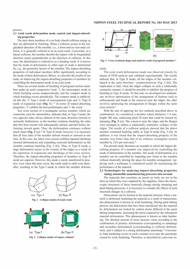
With the aim of applying the two methods described above in combination, we considered a member (sheet thickness 1.4 mm, length 300 mm, embossing pitch 50 mm) that could be formed by stamping (Fig. 3 (a)). The concaves near the edges and the flanges were arranged to induce a rotationally symmetric collapse of the ridges. The results of a collision analysis showed that the above member continued buckling stably in Type II mode (Fig. 3 (b)). In addition, it was found that the impact-absorbing property of the member was better than that of an ordinary rectangular section member by 22% per unit mass.4)
The present study illustrates an example in which the impact-ab-sorbing property of a member was improved by controlling the mode of deformation of the member. The mode of deformation of a member can be controlled by imparting new forms to the member without drastically altering the space for member arrangement. Ap-plying such a technique is considered useful for maximizing the performance of the material.2.2 Technologies for analyzing impact-absorbing properties
taking automobile manufacturing processes into accountThe materials that constitute an actual car body are not in the
form in which they were supplied by the suppliers. Since the micro-scopic structures of these materials change during stamping and paint baking processes, it is necessary to consider the effects of such structural changes in a collision.
Dislocations can be formed in the material structure when a ma-terial is deformed, hardening the material as a result of interactions; this phenomenon is known as work hardening. During paint baking process, the dislocations that have been introduced into the material by deformation are locked by carbon atoms diffused at the paint baking temperature, increasing the stress required for the subsequent material deformation. This phenomenon is known as bake harden-ing. The absolute amount of stress increase varies according to the combination of primary deformation (corresponding to stamping) and secondary deformation (corresponding to collision deforma-tion), and is subject to a strong deformation anisotropy.5) Converse-ly, bake hardening occurs in such a manner as to ease the anisotropy caused by work hardening. Therefore, as described in a previous re-
Fig. 1 Collapse modes of axial crush
Fig. 2 Collapse modes of square column4)
Fig. 3 Cross sectional shape and analysis result of proposed member 4)

NIPPON STEEL TECHNICAL REPORT No. 103 MAY 2013
- 34 -
port,1) it becomes possible to accurately analyze the impact-absorb-ing properties of car bodies using material properties with adding the hardening due to paint baking process to as-received isotropic properties as the material properties during a collision deformation after work hardening + bake hardening. An axial crush test was car-ried out using members subjected to a heat treatment equivalent to paint baking process to validate the above assumption. The test re-sults are described below.
The material used was a 1.2-mm-thickness sheet of dual-phase steel of 980 MPa class (yield strength: 785 MPa, tensile strength: 1,007 MPa, total elongation: 15%, bake hardening: 61 MPa). Hat-shaped members (each measuring 50 mm × 70 mm) and 300-mm-long members (each with a back sheet spot welded at intervals of 30 mm) were prepared and subjected to a drop weight test (drop weight mass: 260 kg, drop height: 3 m).6) To study the influence of the auto-motive paint baking process discussed above, specimens with and without a baking treatment (170°C for 20 min) corresponding to the heat cycle in the paint baking process were tested.
Forming and collisions were coupled for the purposes of FEM analysis. First, a forming analysis of the hat-shaped member was conducted to understand the conditions of deformation of its parts. Using the analysis results as the initial conditions for crash analysis, it was possible to determine the influence of stamping. In addition, to take into consideration the influence of the bake hardening process, the plastic anisotropy of the member was assumed to be the same as that of the blank material; additionally, the work hardening curve for the blank material added uniformly with the amount of bake hardening, measured in accordance with JIS G 3135, was used as the work hardening curve of the member. A Cowper–Symonds strain rate dependence obtained from a tensile test in the range 0.001 to 1,500 s−1 was used as the strain rate dependence of the test mate-rial.
Fig. 4 illustrates the absorbed energies obtained by experiments and calculations at an axial crush distance of 70 mm.6) From the ex-perimental results, it can be seen that the absorbed energy of the material after the baking treatment is about 10% higher than that of the as-stamped material. This is thought to be because the material used in the present study exhibits good bake hardenability. Further-more, the FEM analysis reproduced the experimental results well for both the as-stamped material and the material subjected to bak-ing treatment. Thus, we confirmed that the proposed analytical tech-nique is effective in predicting changes in the energy-absorbing properties of a member resulting from increased material strength imparted by the stamping and paint baking processes.
With the proposed technique, it is possible to accurately predict
the energy-absorbing properties of materials using only the existing material models; there is no need for any additional modules. There-fore, it is expected that the technique will be applied very effectively in the development of car bodies.
3. Prediction of Fracture Behavior During a CrashThe application of high-strength steel to car bodies has helped
reduce their weight. In future, more and more materials of higher strength will be employed to further reduce car body weight. In many cases, use of higher strength material results in a decrease of material ductility. Furthermore, when the material under consider-ation is sheet steel, reducing the material weight results in a decrease in sheet thickness. Therefore, under present conditions, concerns about possible fractures during crash events have become greater than ever before. To address these concerns effectively, it is essential to predict the occurrence of fractures during crash. Here, we de-scribe technologies for predicting fractures of base metals (materi-als) and spot welds that are commonly used for joints in automo-biles.3.1 Prediction of fractures of spot welds
Tensile shear strength (TSS) and cross tensile strength (CTS) are the most commonly used indexes of joint strength of spot welds.7) The former represents the strength of spot welds in the shear direc-tion and the latter in the peel-off direction. It is generally assumed that, in the case of crash, spot welds will fracture when the forces acting upon the weld elements exceed the joint strength. However, it is virtually impossible to conduct a joint strength test of a huge set of car body materials that differ in thickness and strength and to re-flect the test results in an analytical model. Furthermore, it should be noted that, in TSS/CTS tests, the test specimens are not completely free from rotation and deflection;8) hence, the results obtained can hardly be considered indicative of the fracture strength of material under pure shear or peel-off (tensile) conditions.
To address this, we conducted experiments incorporating various materials, spot welding conditions, and test specimen widths, and measured the amounts of rotation/deflection of the test specimens during the experiment. By so doing, we evaluated the forces acting upon each spot weld in the shear and peel-off directions during frac-ture and the force resulting from those forces. We found that, even when the material and spot welding conditions were invariant, the fracture strength (evaluated from the resultant force) changed as the test specimen width was varied.
As shown schematically in Fig. 5, the observed fracture strength is the average stress (σave) at the test specimen end multiplied by the
Fig. 4 Comparisons of absorbed energy during crush with and without heat treatment 6)
Fig. 5 Relationship between stress concentration coefficient (σmax/σave) and d/W 8)

NIPPON STEEL TECHNICAL REPORT No. 103 MAY 2013
- 35 -
cross-sectional area.8) Furthermore, there is a larger stress (σmax) in the vicinity of the spot-weld (nugget) where the fracture actually oc-curs. We consider that the value of σmax is invariant for the same ma-terial spot-welded at similar conditions. Additionally, it should be noted that fracture strength changes with test specimen width be-cause the value of σave changes as the test specimen width is varied. Therefore, we studied the relationship between stress ratio (σmax/σave) and the ratio of nugget diameter d to test specimen width W (d/W)—a geometric parameter of the test specimen. The results are shown in Fig. 5,8) which also illustrates TSS/CTS joint strength test data. The figure demonstrates that the relationship could be expressed by a single curve, regardless of test type and nugget diameter.8)
Using the relationship shown in Fig. 5, we developed new soft-ware (NSafe®-SPOT) coupled with crash analysis codes to predict fracturing of spot welds. With this software, it is relatively easy to accurately predict fractures by inputting the material type and width (test specimen width, W, in Fig. 5; the width of the region covered by the spot weld under consideration in a real structure). Fig. 6 compares the measured and predicted (by the software) TSS for var-ious steels, from mild steel to ultrahigh-strength steel (hot stamped steel). We found that the software accurately predicts TSS of steels over a wide strength range.
We validated the accuracy of prediction of spot weld fractures using the results of an axial crush test of simple members with hat-shaped cross sections.9) The material used was a 980 MPa steel sheet (thickness : 1.4 mm). The central part of the flange was spot welded at intervals of 40 mm so that the weld diameter became 4√t. The test results are shown in Fig. 7. The member began buckling from the top side, against which the drop weight hit. Simultaneously, the
spot welds began to fracture sequentially from the top down. This condition was reproduced well by FEM analysis. Conversely, during spot welding for a weld diameter of 6√t, none of the spot welds fractured during the experiment or analysis, indicating that the ener-gy absorbed during an axial crush was about 10% higher than that absorbed when the weld diameter was 4√t. We attribute this to a de-crease in the constraints of deformation as the spot welds fractured under the 4√t welding conditions. It was also found that the pro-posed fracture prediction technology could predict both the phe-nomenon of fracture of spot welds and the resulting changes in de-formation mode and absorbed energy.3.2 Fracture of material (base metal)
The sheet thickness reduction ratio and forming limit diagram (FLD) are most commonly used to determine the allowance for frac-ture of sheet steel subjected to a large deformation. In particular, a FLD expressed in strain space (strain FLD) is often used to assess fractures during stamping. However, the FLD is known to change according to the deformation history. Therefore, when a change of deformation path occurs, as in multistage stamping or subsequent crash deformation, it becomes necessary to prepare many FLDs to cover all possible deformation paths.
Fig. 8 illustrates the change in forming limits we observed when the deformation path was altered.10) The material used was a 590 MPa precipitation-hardened steel (thickness: 1.2 mm). The figure shows the forming limits measured for three scenarios: ① no pre-strain was applied; ② 10% tension was applied as the primary strain in the rolling direction by a large tensile test specimen and then the direction of tension was aligned to the direction of maximum princi-pal stress (α = 0°); and ③ 10% tension was applied as the primary strain in the rolling direction by a large tensile test specimen and then the orthogonal direction of tension was aligned to the direction of maximum principal stress (α = 90°). In the strain FLD, the form-ing limits change markedly according to the deformation path, as il-lustrated in the figure. Thus, we ascertained the following: (a) when the main axis of strain remains unchanged and the secondary defor-mation is an equibiaxial deformation, the forming limit increases; and (b) when the main axis of strain turns 90°, the forming limits for uniaxial tension and plane strain tension decline considerably, as de-scribed in the previous report. In particular, when the deformation path changes widely it is impossible to secure a high degree of pre-diction accuracy using solely the forming limits without prestrain expressed in strain space.
Fig. 6 Comparison of experimental and analysis results of TSS
Fig. 7 Comparison of deformed shapes of axially crushed parts 9) Fig. 8 Experimental FLDs for proportional and combined loadings 10)
NIPPON STEEL TECHNICAL REPORT No. 103 MAY 2013
- 36 -
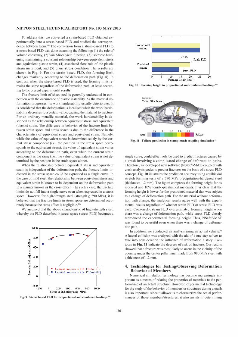
To address this, we converted a strain-based FLD obtained ex-perimentally into a stress-based FLD and studied the correspon-dence between them.10) The conversion from a strain-based FLD to a stress-based FLD was done assuming the following: (1) the rule of volume constancy, (2) von Mises yield function, (3) isotropic hard-ening maintaining a constant relationship between equivalent stress and equivalent plastic strain, (4) associated flow rule of the plastic strain increment, and (5) plane stress condition. The results are shown in Fig. 9. For the strain-based FLD, the forming limit changes markedly according to the deformation path (Fig. 8). In contrast, when the stress-based FLD is used, the forming limit re-mains the same regardless of the deformation path, at least accord-ing to the present experimental results.
The fracture limit of sheet steel is generally understood in con-nection with the occurrence of plastic instability. As the material de-formation progresses, its work hardenability usually deteriorates. It is considered that the deformation is localized when the work harde-nability decreases to a certain value, causing the material to fracture. For an ordinary metallic material, the work hardenability is de-scribed as the relationship between equivalent stress and equivalent (plastic) strain. The difference in behavior of the fracture limit be-tween strain space and stress space is due to the difference in the characteristics of equivalent stress and equivalent strain. Namely, while the value of equivalent stress is determined solely by the cur-rent stress component (i.e., the position in the stress space corre-sponds to the equivalent stress), the value of equivalent strain varies according to the deformation path, even when the current strain component is the same (i.e., the value of equivalent strain is not de-termined by the position in the strain space alone).
When the relationship between equivalent stress and equivalent strain is independent of the deformation path, the fracture limits in-dicated in the stress space could be expressed as a single curve. In the case of mild steel, the relationship between equivalent stress and equivalent strain is known to be dependent on the deformation path in a manner known as the cross effect.11) In such a case, the fracture limits do not fall into a single curve even when expressed in a stress space. However, for high-strength steel (strength ≥ 590 MPa), it is believed that the fracture limits in stress space are determined accu-rately because the cross effect is negligible.11)
We assumed that the above characteristic of high-strength steel, whereby the FLD described in stress space (stress FLD) becomes a
single curve, could effectively be used to predict fractures caused by a crash involving a complicated change of deformation paths. Therefore, we developed new software (NSafe®-MAT) coupled with crash analysis codes to predict fractures on the basis of a stress FLD concept. Fig. 10 illustrates the prediction accuracy using equibiaxial stretch forming tests of a 590 MPa precipitation-hardened steel (thickness: 1.2 mm). The figure compares the forming height for as received and 10% tensile-prestrained materials. It is clear that the forming height is lower for the prestrained material that was subject to a change of deformation path. For the material without deforma-tion path change, the analytical results agree well with the experi-mental results regardless of whether strain FLD or stress FLD was used. Conversely, strain FLD overestimated forming height when there was a change of deformation path, while stress FLD closely reproduced the experimental forming height. Thus, NSafe®-MAT was found to be useful even when there was a change of deforma-tion path.
In addition, we conducted an analysis using an actual vehicle.6) A lateral collision was analyzed with the aid of a one-step solver to take into consideration the influence of deformation history. Con-tours in Fig. 11 indicate the degrees of risk of fracture. Our results showed that a fracture was most likely to occur in the vicinity of the opening under the center pillar inner made from 980 MPa steel with a thickness of 1.2 mm.
4. Technologies for Testing/Observing Deformation Behavior of MembersNumerical simulation technology has become increasingly im-
portant as a means of relating the properties of materials to the per-formance of an actual structure. However, experimental technology for the study of the behavior of members or structures during a crash is also important, since it allows us to characterize the actual perfor-mances of those members/structures; it also assists in determining Fig. 9 Stress based FLD for proportional and combined loadings 10)
Fig. 11 Failure prediction in stamp-crash coupling simulation 6)
Fig. 10 Forming height in proportional and combined loadings 10)

NIPPON STEEL TECHNICAL REPORT No. 103 MAY 2013
- 37 -
the influences of factors that have not yet been fully reflected in nu-merical simulations and helps validate the results of various studies conducted using numerical simulations. Here, we introduce technol-ogy for high-accuracy measurement of dynamic force and a recently installed impact testing facility capable of covering the impact ve-locity range appropriate for all current new car assessment pro-grams.
The difficulty involved in measuring such dynamic forces as ob-served in crashes lies in their tendency to propagate through the rel-evant medium in the form of elastic waves. With conventional measurement techniques, it is usually difficult to observe the true force since the elastic waves that propagate through various parts of the testing machine undergo multiple reflections and overlap to pro-duce a violent vibration. To prevent such phenomena, improvements have been made to the force measuring unit.12) The improved force measuring unit is illustrated schematically in Fig. 12; it consists of two plates and one solid cylinder. Plate No. 1 also serves as the fixed part of the testing structure and the force applied is transmitted to the cylinder via this plate. Then, the elastic strain at the center of the cylinder is measured by, e.g., a strain gauge. It is important to note that there is a large difference in cross-sectional area between the cylinder and each of the two plates and that the cylinder has a small height to cross-sectional area ratio. This configuration allows shortening of the time required to make the elastic deformation of the cylinder uniform and restrain the occurrence of an oscillatory waveform.
Fig. 12 (a) shows the results obtained by applying the above de-vice in an axial crush test of a hat-shaped member (590 MPa precip-itation-hardened steel sheet, 1.4 mm in thickness, and 60 mm × 60 mm in cross section). While the force waveform displays several peaks, a comparison of the force waveform with the deformation profile measured at the same time (Fig. 12 (b)) indicates that, as the
member began buckling from the top end, the back sheet side and the hat side began to experience an out-of-plane deformation (indi-cated by an arrow in the diagram) simultaneously. Thus, we found that it is possible to measure the dynamic force with a high degree of accuracy.
The overview of the impact testing machine is shown in Table 1. This machine can be used for crash tests of both individual members and large structures. Employing a hydraulic, horizontal impact sys-tem, the machine permits evaluation of diverse crash modes. The maximum impact velocity is 100 km/h, meaning that the machine covers the entire velocity range required for crash testing in current automotive assessment. In addition, various types of high-precision measuring devices are available, allowing for detailed observation of the behavior of members and structures during crash. Thus, with the above impact testing machine, it is possible to evaluate the im-pact-absorbing properties and study the mechanisms of deformation of members and structures of automobiles.
5. ConclusionWe conducted fundamental research into technologies that fully
incorporate material performance in the consideration of impact-ab-sorbing properties of car bodies. We introduced several types of techniques to achieve the following goals: control the modes of de-formation and study the influences of car manufacturing processes; predict fractures of spot welds and base metals in order to prevent them; allow sophisticated testing and evaluation; and develop an impact testing machine. In future, we intend to continue developing our technologies with the aim of offering advanced new materials and optimum application technologies to meet increasingly sophisti-cated customer needs.
References1) Hirose, S., Uenishi, A., Yonemura, S., Hiwatashi, S.: Nippon Steel Tech-
nical Report. (103), 25-31 (2013)2) Reid, S.R.: Int. J. Mech. Sci. 28, 295 (1986)3) Abramowicz, W., Jones, N.: Int. J. Impact Engineering. 2, 179 (1984)4) Hirose, S., Uenishi, A.: Collection of Lecture Papers for the 62nd Joint
Lecture Meeting of the Japan Society for Technology of Plasticity. 563 (2011)
5) Yonemura, S., Hiwatashi, S., Uenishi, A., Usuda, M.: Tetsu-to-Hagané. 92 (8), 516 (2006)
6) Yonemura, S., Hiwatashi, S., Hirose, S., Uenishi, A., Suzuki, N., Yoshi-da, H.: Collection of Preprints of Academic Lectures of the Society of Automotive Engineers of Japan. No. 15-09, 20095404, 2009
7) Oikawa, H., Murakami, G., Sakiyama, T., Takahashi, Y., Ishikawa, T.: Nippon Steel Technical Report. (95), 39 (2007)
8) Yoshida, H., Uenishi, A., Kuriyama, Y., Nomura, N.: Collection of Pre-prints of Academic Lectures of the Society of Automotive Engineers of Japan. No. 8-04, 20045205, 2004
9) Yoshida, H., Uenishi, A., Nomura, N.: Collection of Preprints of Aca-demic Lectures of the Society of Automotive Engineers of Japan. No. 49-05, 20055062, 2005
10) Yonemura, S., Yoshida, H., Uenishi, A., Hiwatashi, S.: Collection of Pre-prints of Academic Lectures of the Society of Automotive Engineers of Japan. No. 21-07, 20075066, 2007
11) Yonemura, S., Uenishi, A., Hiwatashi, S., Suzuki, N., Usuda, M.: Tetsu-to-Hagané. 93 (4), 317 (2007)
12) Patent No. 4741272/Patent No. 4741273
Fig. 12 Example of dynamic force measurement in axial crush
Table 1 Overview of impact testing machine
Method Hydraulic type, horizontal impactImpact velocity range 2-100km/h
Measurement equipment High-speed camera, Force, etc.

NIPPON STEEL TECHNICAL REPORT No. 103 MAY 2013
- 38 -
Akihiro UENISHIChief Researcher, Dr.Sheet Products Lab.Steel Research Laboratories20-1 Shintomi, Futtsu, Chiba 293-8511
Shigeru YONEMURASenior Researcher, Dr.Eng.Kimitsu R&D Lab.
Satoshi HIROSESenior Researcher, Ph.D.Forming Technologies R&D CenterSteel Research Laboratories
Hiroshi YOSHIDASenior Researcher, Ph.D.Forming Technologies R&D CenterSteel Research Laboratories
Shunji HIWATASHIChief Researcher, Ph.D.General ManagerNagoya R&D Lab.
Naruhiko NOMURASenior ResearcherForming Technologies R&D CenterSteel Research Laboratories
Yasunori ITODepartment ManagerQuality Management Div.Nagoya Works
Kazuyuki KAWANOAssistant General ManagerQuality Management Div.Nagoya Works