technical report udc 629 . 11 . 012 . 8 development of ... · in 2001, pneumatically actuated...
TRANSCRIPT
NIPPON STEEL & SUMITOMO METAL TECHNICAL REPORT No. 105 DECEMBER 2013
- 48 -
1. IntroductionActive suspension systems are provided to improve the ride
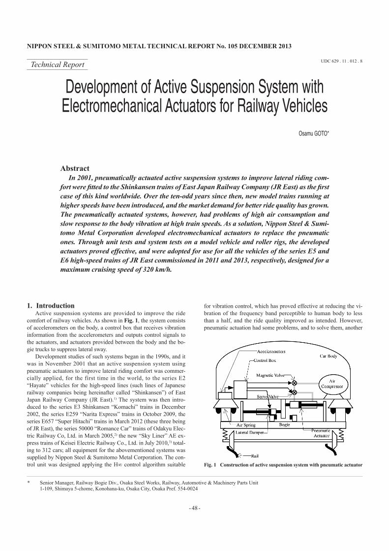
comfort of railway vehicles. As shown in Fig. 1, the system consists of accelerometers on the body, a control box that receives vibration information from the accelerometers and outputs control signals to the actuators, and actuators provided between the body and the bo-gie trucks to suppress lateral sway.
Development studies of such systems began in the 1990s, and it was in November 2001 that an active suspension system using pneumatic actuators to improve lateral riding comfort was commer-cially applied, for the first time in the world, to the series E2 “Hayate” vehicles for the high-speed lines (such lines of Japanese railway companies being hereinafter called “Shinkansen”) of East Japan Railway Company (JR East).1) The system was then intro-duced to the series E3 Shinkansen “Komachi” trains in December 2002, the series E259 “Narita Express” trains in October 2009, the series E657 “Super Hitachi” trains in March 2012 (these three being of JR East), the series 50000 “Romance Car” trains of Odakyu Elec-tric Railway Co, Ltd. in March 2005,2) the new “Sky Liner” AE ex-press trains of Keisei Electric Railway Co., Ltd. in July 2010,3) total-ing to 312 cars; all equipment for the abovementioned systems was supplied by Nippon Steel & Sumitomo Metal Corporation. The con-trol unit was designed applying the H∞ control algorithm suitable
for vibration control, which has proved effective at reducing the vi-bration of the frequency band perceptible to human body to less than a half, and the ride quality improved as intended. However, pneumatic actuation had some problems, and to solve them, another
Technical Report UDC 629 . 11 . 012 . 8
* Senior Manager, Railway Bogie Div., Osaka Steel Works, Railway, Automotive & Machinery Parts Unit 1-109, Shimaya 5-chome, Konohana-ku, Osaka City, Osaka Pref. 554-0024
Development of Active Suspension System with Electromechanical Actuators for Railway Vehicles
Osamu GOTO*
AbstractIn 2001, pneumatically actuated active suspension systems to improve lateral riding com-
fort were fitted to the Shinkansen trains of East Japan Railway Company (JR East) as the first case of this kind worldwide. Over the ten-odd years since then, new model trains running at higher speeds have been introduced, and the market demand for better ride quality has grown. The pneumatically actuated systems, however, had problems of high air consumption and slow response to the body vibration at high train speeds. As a solution, Nippon Steel & Sumi-tomo Metal Corporation developed electromechanical actuators to replace the pneumatic ones. Through unit tests and system tests on a model vehicle and roller rigs, the developed actuators proved effective, and were adopted for use for all the vehicles of the series E5 and E6 high-speed trains of JR East commissioned in 2011 and 2013, respectively, designed for a maximum cruising speed of 320 km/h.
Fig. 1 Construction of active suspension system with pneumatic actuator

NIPPON STEEL & SUMITOMO METAL TECHNICAL REPORT No. 105 DECEMBER 2013
- 49 -
system based on electromechanical actuation has been newly devel-oped and put into commercial use. This paper reports the details of the newly developed electromechanical active suspension system.
2. Problems with Pneumatic Vibration Suppression System
2.1 Compressed air consumptionA major problem with the pneumatic system was the large con-
sumption of compressed air by the actuators. Railway vehicles use compressed air for brakes, height control with air springs, doors, toilet flushing, etc., but the total consumption is limited by the heat capacity of the reciprocating air compressors. On the other hand, higher vibration damping capacity means greater consumption of compressed air, and for this reason, it was considered difficult to provide all the cars of a train with pneumatic active suspension sys-tems.
In view of this, Nippon Steel & Sumitomo Metal began develop-ment of pneumatic actuators of a low-air-consumption type having less air consumption than that of conventional ones by 30 to 50% (see Fig. 2), and after tests on a roller rig, fitted them to real vehicles for trial use in December 2003 to obtain satisfactory results. Then, in June 2008, jointly with Deutsche Bundesbahn (German federal railway company), the developed actuators were installed on the German three-car test train ICE-S together with centering actuators (see Fig. 3), and subjected to a series of tests at 300 km/h. The result was that the root mean square (RMS) of the vehicle body’s lateral acceleration was reduced to virtually half. Later, however, through tests on the MUE-Train of JR East in April 2009, it became clear that the effects of the new type actuators were decreased at curves
where large actuation strokes were required.4)
Nevertheless, Kintetsu Corporation combined Nippon Steel & Sumitomo Metal’s pneumatic oscillation control system with scroll-type air compressors in order to allow for large air consumption and installed them on all the cars of the Premium Express Trains “Shima-kaze,” which entered into commercial operation in March 2013.2.2 Frequency response
A second problem with the pneumatic actuators was frequency response. With the latest increase in train speed, the frequency of vehicle vibration has increased, and consequently, higher response is required for the actuators to suppress it. Because of the compress-ibility of air, however, the response of pneumatic actuators is limit-ed. In addition, when tilting control is provided to reduce steady lat-eral acceleration at curves to allow high-speed running, a longer stroke is required for the horizontal actuators provided between the bogies and the body, which means a larger cylinder capacity.
This inevitably leads to poorer response of the pneumatic actua-tors; for example, when the stroke is doubled, the response decreas-es to a half. A measure to avoid the deterioration of response is to decrease the sectional area of the cylinder, although this decreases the maximum thrust. As a countermeasure, a new type of pneumatic system was developed: the cylinder inner diameter was reduced from 100 to 80 mm, the response increased 1.6 times, although the maximum thrust decreased by 36%. This system is being used on the above-mentioned type AE express trains “Sky Liner” of Keisei, running at a maximum cruising speed of 160 km/h, the fastest oper-ation in Japan except on Shinkansen lines. The higher response of this system has proved effective at decreasing air consumption.2.3 Motivation for developing electric actuation
To solve the above problem of pneumatic actuators, JR East de-cided in January 2004 to use new direct-acting electromagnetic ac-tuators for the series E954 and E955 high-speed test trains aiming at developing a next-generation Shinkansen operation.5,6) To this end, Nippon Steel & Sumitomo Metal started development of a new high-response electric actuator, which would not consume com-pressed air, to be in time for the next-generation operation.7)
3. Investigation into Electric Actuators3.1 Required specifications for electric actuators
The specifications of the present pneumatic actuators are as fol-lows.
(1) Maximum continuous thrust: 6 kN(2) Frequency band of vibration to control: 3 Hz or lower(3) Unit mass: approx. 20 kg
As stated in Sub-section 2.2 above, lateral acceleration of vehi-cle bodies increases with increasing train speed owing to aerody-namic turbulence.8) When, for example, series E2 and E3 Shinkan-sen trains of JR East run coupled together, this becomes pronounced especially with the section behind the coupling. Therefore, at higher speeds, higher thrust than that of pneumatic actuators is required in wider frequency bands. Assuming the same outer dimension, elec-tric actuators are generally better in response but poorer in continu-ous thrust when compared with pneumatic ones. In other words, an electric actuator having the same continuous thrust as that of a pneu-matic one will be too heavy to suitably fit into a bogie truck. In view of this, the required specifications of the electric actuator were de-fined as follows.
(1) Maximum thrust: 8 kN or more(2) Continuous thrust: 3 kN or more(3) Frequency band of vibration to control: 5 Hz or higher
Fig. 2 Pneumatic actuator with reduced air consumption
Fig. 3 Fitting pneumatic actuators on bogie for ICE-S

NIPPON STEEL & SUMITOMO METAL TECHNICAL REPORT No. 105 DECEMBER 2013
- 50 -
(4) Unit mass: 36 kg or less (comparable with a yaw damper)(5) Size: to be fitted into bogie frames without major modifica-
tions.3.2 Comparison between electric actuators
In search of electric actuators as specified in Sub-section 3.1, in-formation was collected from actuator manufacturers and research institutes in and outside Japan. Table 1 summarizes the collected in-formation.
The characteristics of different types of electric actuators are de-scribed below.
The electromechanical actuator (EMA) converts the rotation of a built-in electric motor into linear movement using a drive mecha-nism, which may be a ball screw or a roller screw. Since the latter uses line contact for force transfer, it is superior in terms of durabili-ty to the former, which uses point contact. For this reason, the actua-tors for the body tilting systems presently used in Germany, the U.K., and Spain are of the roller screw type. While the most serious concern about this type of actuator is the sticking of the drive mech-anism, there have been no such reports.
The electro-hydraulic actuator (EHA) comprises an electric mo-tor and a hydraulic pump as integral parts, and for this reason, the vehicle is not required to have a hydraulic system separately. This type of actuator is considered promising for the next-generation body tilting systems for European railways, and the Railway Tech-nical Research Institute of Japan is also developing a variety of ap-plications for the EHA.9)
The voice coil motor (VCM) is a linear actuator like the one used for driving the coil of a loud speaker. Thrust is generated by the Lorentz force arising from an electric current applied to a mov-able coil in the magnetic field of a permanent magnet, but it is im-possible to obtain large strokes.
The linear synchronous motor (LSM) is a direct-acting synchro-nous motor; thrust is generated by the attraction between a perma-nent magnet and a shifting magnetic field formed by electromagnets arranged in the direction of the thrust. Although this motor has high cost, its control is simple, its efficiency is high, and it is versatile with respect to stroke. Like VCM, however, its downsizing and power increase depend on intensification of the flux density of the permanent magnet, and products that met the required specifications were not available in the market at the time of the research in 2004.3.3 Opting for EMA
In the first place in the comparative study of the above mecha-nisms, since the EHA included a hydraulic system, it was feared that it would require considerable amount of maintenance labor, and un-suitable in consideration of the present field practice of vehicle maintenance.
In the second place, the VCM was examined in more details in view of the fact that it does not use any mechanical parts, which are prone to troubles, to convert electric energy into kinetic energy. But,
according to a study report, even if the required maximum thrust was decreased to 4.5 kN, the unit mass would exceed 200 kg, and another said that if the unit mass was decreased to 53 kg, the maxi-mum thrust would be only 1.5 kN, and the stroke of actuation as small as ±10 mm.
Thus, Nippon Steel & Sumitomo Metal decided against using the VCM and instead chose to pursue the comparatively light and powerful EMA, while aiming at differentiating the development fruit from those of competitors.
4. Performance TestOf the performance items of the EMA, its basic capability to
damp vibration was evaluated in the first place.4.1 Trial production of electromechanical actuators
Units of the EMA were manufactured for test purposes; Fig. 4 shows an example. The specifications for the trial products were de-fined as follows to satisfy the initial requirements.
(1) Maximum thrust: 8.5 kN(2) Continuous thrust: 4 kN(3) Frequency band of vibration to control: 10 Hz or higher(4) Unit mass: approx. 29 kg
What was of special importance in defining the trial production specifications was the lead of the roller screw, as it had significant effects on the back-drive force. Because the lowest operating pres-sure of pneumatic actuators is 50 kPa or lower, by multiplying it by the cylinder sectional area, its back-drive force is estimated at 345 N or less. Based on this, the back-drive force of the EMA was set at 560 N or less so that the stroke could be adjusted by manual force, and to make it possible, the lead was set at 20 mm. With a shorter lead, the motor rotation will be higher, the energy conversion effi-ciency higher, and the motor size smaller. On the other hand, how-ever, the back-drive force will increase, and it was feared that the ride quality would be poor when the control is switched off. Later, EMA units having a lead of 10 mm were tested; however, the back-drive force was excessively large and interfered with its own thrust exertion.4.2 Method of performance test
To evaluate if the EMA had satisfactory performance, trial prod-ucts were tested using a real-size model vehicle shown in Fig. 5: it consisted of a simulated body, two real bogie frames set at 13.8 m from each other, and a hydraulic actuator fixed to each of the bogie frames to apply lateral accelerations independently from each other to simulate the vibration of running vehicles.
The concept of the control command for the hydraulic actuators to simulate the vibration of real vehicles is as shown in Fig. 6, where u is the lateral acceleration measured on a real vehicle body, B.P.F. is a band-pass filter that defines the frequency band of the ac-celeration to reproduce, G(s) is the function of force transfer from the vibration commands given to the hydraulic actuators to the later-
Fig. 4 Trial product of EMA
Table 1 Comparison of actuators
Type Response Weight GearHeat
generationOil
Pneumatic Light NoneEMA High Required Low RequiredEHA High High RequiredVCM High Heavy HighLSM High Heavy High

NIPPON STEEL & SUMITOMO METAL TECHNICAL REPORT No. 105 DECEMBER 2013
- 51 -
al acceleration of the simulated body of the model vehicle, and y is the vibration command given to the actuators.
For example, assuming the value of the vibration command for the front bogie as y and shifting the phase of the vibration applied to the rear bogie by 180˚, the equation of motion for the body yawing Lφ is given by Equation (1). Note here that force transfer character-istics of the actuators are negligible because the response of the hy-draulic actuators is sufficiently high compared with the same of a vehicle.
mi2 Lϕ t = − 2c Lϕ t − u t − Δt L− 4k Lϕ t − u t − Δt L (1)
Through the Laplace transformation and rearrangement of Equa-tion (1), the function G(s) of the force transfer from the value of the yawing acceleration command y to the actual yawing acceleration is given by Equation (2):
G s = s
2 L ϕy = s2 2cL2s + 4kL2
mi2 s2 + 2cL2 s + 4kL2 e− Δts
(2)
By fitting the transfer function G(s) to the measurement results of acceleration tests at different frequencies so as to minimize the deviations as shown in Fig. 7, the parameters used in the function were defined as given in Table 2.
Then, the value of the yawing acceleration command y was ob-tained by applying the measured yawing acceleration u to the in-verse function G−1(s) given as Equation (3). An example of such cal-culation results is shown in Fig. 8, and the agreement between the test results on the model vehicle and the calculation in Figs. 9 and 10. The simulation results agreed well with the measured results in the frequency band of the vibration, which indicates that it is possi-ble to assess the performance of the actuators before actually using them on real vehicles.
G−1 s = mi
2 s2 + 2cL2 s + 4kL2s2 2cL2s + 4kL2 eΔts
(3)
4.3 Results of performance testTo compare the EMA and the pneumatic actuator in terms of
ride quality improvement effects, an EMA was installed at the body-end side of the king pin of each bogie of the model vehicle, and a pneumatic actuator on the other side; an EMA unit fitted to one of the bogie frames of the model vehicle is shown in Fig. 11.
Figure 12 compares the lateral acceleration waves of the model
Fig. 7 Result of parameter identification for yawing estimation
Fig. 8 Control command for simulating real lateral acceleration
Table 2 Parameter values
Parameter Value SignVehicle weight 30 t m
Inertia radius of yawing 4.53 m iDistance between bogies 13.8 m 2L
Air spring 160 kN/m kLateral damper 18 kNs/m c
Delay time 18 ms Δt
Fig. 9 Measured and simulated power sector density
Fig. 5 Model vehicle for test
Fig. 6 Control command to hydraulic actuators

NIPPON STEEL & SUMITOMO METAL TECHNICAL REPORT No. 105 DECEMBER 2013
- 52 -
vehicle body in the cases of no vibration control (passive suspen-sion) and control using pneumatic and electromechanical actuators. The lateral acceleration of the vehicle body was evaluated in terms of the RMS and the ride quality level LT specified in ISO 2631-1 (1997). Table 3 shows the evaluation results: the pneumatic actuator reduced the RMS to a half without vibration control, and decreased (improved) the ride quality level LT by roughly 6 dB. In comparison,
the EMA decreased the RMS to one-third, and the value of LT by roughly 10 dB, evidently showing performance superior to that of the pneumatic. However, as is clear from the vibration wave form, the vibration under the EMA control tended rather to increase in the high-frequency band above that of vehicle vibration because of its high response. This can be remedied by adequately modifying the weight function for the vibration acceleration or the control com-mand at the design stage of the controller based on the H∞ control theory.
5. Endurance TestAfter confirming the EMA’s sufficiently good ride quality im-
provement performance as described above, the actuators underwent various endurance tests to verify their suitability for actual use.5.1 Heat generation of actuators
Electric actuation inevitably incurs energy loss in the form of heat when electric energy is converted into kinetic energy. In con-sideration of this, the developed EMA units were subjected to con-tinuous actuation test at positions where they would not be cooled by air during running. The measured temperature rise of the EMA is given in Fig. 13; the readings are those at the surface of the motor casing—the position where the temperature is highest. After an op-eration for 2 h, the temperature rose by as little as 14˚C, which dem-onstrates that the heat generation of the EMA would not pose any problem for use on real vehicles.
In addition to the above, to examine the performance of an LSM introduced by a competitor into the market, LSM units were manu-factured for test purposes according to the specifications of the com-petitor given below, installed in the model vehicle, and subjected to a series of tests. Eventually, the temperature rose to greater than 100°C within a few minutes of testing, which indicated that the LSM was unsuitable for the application because of the heat genera-tion, in addition to its heavy weight (see Fig. 14).
(1) Maximum thrust: 3.6 kN(2) Continuous thrust: 1.3 kN(3) Frequency band of vibration to control: 10 Hz or higher(4) Unit mass: 68 kg(5) Outer diameter: 178 mm
5.2 Lateral loading testIn the same manner as the endurance test of pneumatic actuators,
the EMA units underwent continuous actuation test under the condi-tions given below; here pinching loads were applied to the rubber cushions at both the mounting ends. However, soon after the start of the test, the bearings began to show abnormal wear, and also the roller screw was damaged as shown in Fig. 15.
(1) Reaction force of the rubber cushion: 140 Nm(2) Amplitude: ±5 mm(3) Frequency: 5 Hz(4) Bogie inspection interval: 1,068 h (calculated assuming a run-
ning distance of 600,000 km)It became clear from the above that the EMA was very vulnera-
ble to lateral loads. As a countermeasure, special spherical bearings
Table 3 Evaluations of RMS
Control type RMS LT
Passive 0.172 m/s2 88.5 dBPneumatic 0.083 m/s2 81.9 dB
EMA 0.051 m/s2 77.6 dB
Fig. 10 Measured and simulated lateral acceleration waves
Fig. 11 Fitting EMA onto model vehicle
Fig. 12 Lateral acceleration by different control methods

NIPPON STEEL & SUMITOMO METAL TECHNICAL REPORT No. 105 DECEMBER 2013
- 53 -
rotating about only two axes were newly designed (see Fig. 16) and used to allow for the displacement of bogies with respect to the body; the displacement was taken care of by rubber cushions. Here,
the move about the third axle was restricted by the linear contact be-tween a cylindrical surface and a flat plane. The reason for restrict-ing the turn of the thrust shaft by using the spherical bearing is that restricting it inside the EMA will increase the reaction force, and the reason why it is restricted at all is to prevent the EMA from falling down. To cut the vibration from the bogies and electrically insulate the body from the bogies, a structurally simple rubber cushion ring was used only on the bogie side where heating of the motor would not cause any problems.
Without the spherical bearings, the lateral loading test was con-tinued to the end of the truck inspection interval (corresponding to 600,000 km running) leaving the damaged roller screw unattended and without lubricant inside the unit. Nevertheless, sticking did not occur, and as seen with Fig. 17, the EMA was little affected by the problems and continued working effectively in the frequency band of vibration. This test was continued to complete a period of general vehicle inspection (corresponding to 1,200,000 km running), but still no sticking occurred.5.3 Tests with iron fines
Next, 0.8 g of iron fines roughly length 0.5 mm × width 0.1 mm in size were intentionally mixed into the lubricant of the EMA units, and for comparison with normal ones, the units underwent unit ac-tuation test on a test rig and vibration control test on the model vehi-cle. In either test, no sticking occurred to the units in question, but the lateral ride quality level deteriorated by about 2 dB. Sticking did not occur presumably because the iron fines were crushed as they passed through the gaps of the roller screw.
Since lubricant containing iron fines or other foreign matter de-teriorates the service life of lubricated parts, magnetic plugs were provided for the EMA units at commercial manufacture for mainte-nance purposes.5.4 Test of simulated sticking
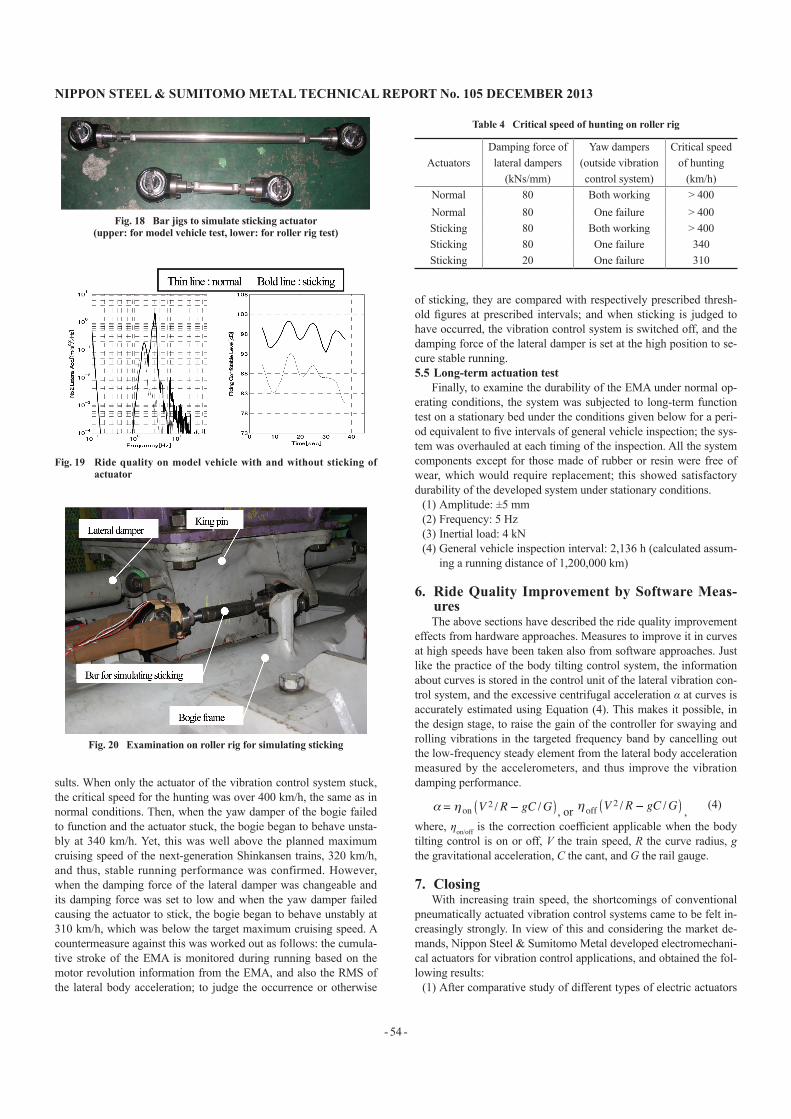
Although the EMA proved considerably free from sticking through the above tests, it was necessary to confirm how the vehicle would behave if sticking occurred. For this purpose, bar jigs to sim-ulate sticking actuators were prepared (see Fig. 18).
First, the restricting jig was fitted to the No. 2 bogie of the model vehicle, and vibration simulating track misalignment was applied; the result is shown in Fig. 19. Since the vibration of the bogie was transferred to the body directly, the vibration of frequencies higher than 2 Hz increased significantly, and the ride quality level deterio-rated by about 10 dB.
After the above, the restricting jig was fitted to a bogie on a roll-er rig (see Fig. 20) in order to examine the critical speed for the bo-gie hunting due to self-excited vibration; Table 4 shows the test re-
Fig. 13 Heat generation from EMA motor
Fig. 14 Fitting LSM onto model behicle
Fig. 15 Failure of roller screw
Fig. 16 Spherical bearing restricting pitching rotation
Fig. 17 Frequency characteristics of control force
NIPPON STEEL & SUMITOMO METAL TECHNICAL REPORT No. 105 DECEMBER 2013
- 54 -
sults. When only the actuator of the vibration control system stuck, the critical speed for the hunting was over 400 km/h, the same as in normal conditions. Then, when the yaw damper of the bogie failed to function and the actuator stuck, the bogie began to behave unsta-bly at 340 km/h. Yet, this was well above the planned maximum cruising speed of the next-generation Shinkansen trains, 320 km/h, and thus, stable running performance was confirmed. However, when the damping force of the lateral damper was changeable and its damping force was set to low and when the yaw damper failed causing the actuator to stick, the bogie began to behave unstably at 310 km/h, which was below the target maximum cruising speed. A countermeasure against this was worked out as follows: the cumula-tive stroke of the EMA is monitored during running based on the motor revolution information from the EMA, and also the RMS of the lateral body acceleration; to judge the occurrence or otherwise
of sticking, they are compared with respectively prescribed thresh-old figures at prescribed intervals; and when sticking is judged to have occurred, the vibration control system is switched off, and the damping force of the lateral damper is set at the high position to se-cure stable running.5.5 Long-term actuation test
Finally, to examine the durability of the EMA under normal op-erating conditions, the system was subjected to long-term function test on a stationary bed under the conditions given below for a peri-od equivalent to five intervals of general vehicle inspection; the sys-tem was overhauled at each timing of the inspection. All the system components except for those made of rubber or resin were free of wear, which would require replacement; this showed satisfactory durability of the developed system under stationary conditions.
(1) Amplitude: ±5 mm(2) Frequency: 5 Hz(3) Inertial load: 4 kN(4) General vehicle inspection interval: 2,136 h (calculated assum-
ing a running distance of 1,200,000 km)
6. Ride Quality Improvement by Software Meas-uresThe above sections have described the ride quality improvement
effects from hardware approaches. Measures to improve it in curves at high speeds have been taken also from software approaches. Just like the practice of the body tilting control system, the information about curves is stored in the control unit of the lateral vibration con-trol system, and the excessive centrifugal acceleration α at curves is accurately estimated using Equation (4). This makes it possible, in the design stage, to raise the gain of the controller for swaying and rolling vibrations in the targeted frequency band by cancelling out the low-frequency steady element from the lateral body acceleration measured by the accelerometers, and thus improve the vibration damping performance.
α = η on V 2 /R − gC /G , or η off V2 /R − gC /G , (4)
where, ηon/off is the correction coefficient applicable when the body tilting control is on or off, V the train speed, R the curve radius, g the gravitational acceleration, C the cant, and G the rail gauge.
7. ClosingWith increasing train speed, the shortcomings of conventional
pneumatically actuated vibration control systems came to be felt in-creasingly strongly. In view of this and considering the market de-mands, Nippon Steel & Sumitomo Metal developed electromechani-cal actuators for vibration control applications, and obtained the fol-lowing results:
(1) After comparative study of different types of electric actuators
Table 4 Critical speed of hunting on roller rig
ActuatorsDamping force of lateral dampers
(kNs/mm)
Yaw dampers(outside vibration control system)
Critical speed of hunting
(km/h)Normal 80 Both working > 400Normal 80 One failure > 400Sticking 80 Both working > 400Sticking 80 One failure 340Sticking 20 One failure 310
Fig. 18 Bar jigs to simulate sticking actuator(upper: for model vehicle test, lower: for roller rig test)
Fig. 19 Ride quality on model vehicle with and without sticking of actuator
Fig. 20 Examination on roller rig for simulating sticking

NIPPON STEEL & SUMITOMO METAL TECHNICAL REPORT No. 105 DECEMBER 2013
- 55 -
available in the market, and in consideration of differentiating the development fruit from competitors’ products, the company selected electromechanical actuation, and developed a new model of actuator for the application.
(2) The developed electromechanical actuator (EMA) proved highly durable through various tests.
(3) After evaluation by JR East, the vibration control system using
the EMA was adopted for all the vehicles of the series E5 and E6 Shinkansen trains (see Figs. 21 and 22).10)
Nippon Steel & Sumitomo Metal will continue watching the technical trend of the railway industry and will pursue further possi-bilities of both pneumatic and electromechanical actuation.
References1) Tahara, M. et al.: Practical Use of an Active Suspension System for Rail-
way Vehicles. International Symposium on Speed-up and Service Tech-nology for Railway and Maglev Systems. 2003, p. 225-228
2) Kijima, H.: The Advent of Odakyu’s Type 50000 Romance Cars. Japa-nese Railway Engineering. (156), 22-25 (2006)
3) Sawada, et al.: Development of Truck Bogies for AE Express Trains of Keisei Electric Railway Co., Ltd. and Active Suspension. Rolling Stock and Technology. (157), 10-13 (2009)
4) Uekura, et al.: Development of Active Suspension Control System by Actuator of Decreased Air Consumption. Proc. 17th Jointed Railway Technology Symposium. Japan Society of Mechanical Engineers, S5-1-1, 305-308 (2010)
5) Makino, et al.: Development of Active Suspension System Using Elec-tric Linear Motors for Railway Cars. Proc. 13th Jointed Railway Tech-nology Symposium. Japan Society of Mechanical Engineers, No. 06-52, 519-522 (2006)
6) Iwanami, et al.: Development of Active Suspension for Railway Vehicles Using Electromagnetic Actuator. Proc. 13th Jointed Railway Technology Symposium. Japan Society of Mechanical Engineers, No. 06-52, 523-524 (2006)
7) Goto, O. et al.: The Development of an Active Suspension System with EMA for Railway Vehicles. International Symposium on Speed-up and Service Technology for Railway and Maglev Systems. 2009
8) Fujimoto, et al.: Lateral Vibration of Shinkansen Vehicles and Counter-measures. Quarterly Report of RTRI. 9 (1), 19-24 (1995)
9) Kamoshita, et al.: Electro-hydraulic Actuators for New Type Railway Vehicle with Tilting Control. RRR. 62 (5), 24-27 (2005)
10) Tajima: Driving Bogies for Series E5 Shinkansen Vehicles. Rolling Stock and Technology. (157), 7-9 (2009)
Fig. 21 EMA for E5 series Shinkansen train
Fig. 22 Fitting EMA on bogie for E6 series Shinkansen train
Osamu GOTOSenior ManagerRailway Bogie Div., Osaka Steel WorksRailway, Automotive & Machinery Parts Unit1-109, Shimaya 5-chome, Konohana-ku, Osaka City, Osaka Pref. 554-0024