ucs storage integration, technologies, and...
TRANSCRIPT

UCS Storage Integration, Technologies, and
TopologiesCraig Ashapa, Technical Marketing Engineer
BRKCOM-2007
Agenda Cisco VIC Technologies
UCS Storage Modes of Operation and Recommendations
FC/FCoE Uplink Connectivity
Direct Connectivity of Storage
IP-Based Storage
Storage Acceleration
UCS Mini
New Miscellaneous
UCS 3000 Series
Storage Profiles
UCS M-Series
Monitoring, Troubleshooting, Advanced CLI
Cisco VIC Technologies
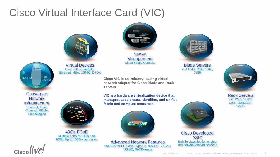
Cisco Virtual Interface Card (VIC)
Cisco Developed ASIC
Built-in classification engine and network offload services
Blade ServersVIC 1240, 1280, 1340,
1380
40Gb FCoEMultiple ports of 10Gb and
40Gb. Up to 160Gb per serverAdvanced Network Features
VM-FEX for ESX and Hyper-V, NVGRE, VXLAN, USNIC, RoCE-ready
Server Management
Cisco Single-ConnectVirtual DevicesOver 256 per adapter
Ethernet, HBA, USNIC, DPDK
Converged Network
InfrastructureEthernet, Fibre
Channel, RDMA Technologies
Virtual
Physical
Ethernet Fibre
Channel
Rack ServersVIC 1225, 1225T, 1285, 1385,1227,
1227T
Cisco VIC is an industry leading virtual
network adapter for Cisco Blade and Rack
servers.
VIC is a hardware virtualization device that
manages, accelerates, identifies, and unifies
fabric and compute resources.
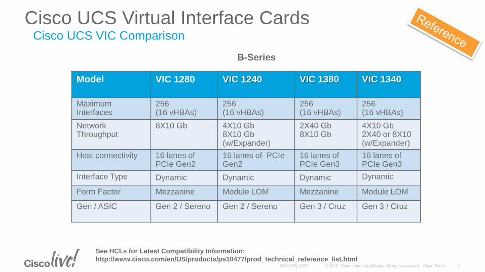
Cisco UCS Virtual Interface Cards
Model VIC 1280 VIC 1240 VIC 1380 VIC 1340
Maximum Interfaces
256(16 vHBAs)
256(16 vHBAs)
256(16 vHBAs)
256(16 vHBAs)
Network Throughput
8X10 Gb 4X10 Gb8X10 Gb (w/Expander)
2X40 Gb8X10 Gb
4X10 Gb2X40 or 8X10(w/Expander)
Host connectivity 16 lanes of PCIe Gen2
16 lanes of PCIe Gen2
16 lanes of PCIe Gen3
16 lanes of PCIe Gen3
Interface Type Dynamic Dynamic Dynamic Dynamic
Form Factor Mezzanine Module LOM Mezzanine Module LOM
Gen / ASIC Gen 2 / Sereno Gen 2 / Sereno Gen 3 / Cruz Gen 3 / Cruz
See HCLs for Latest Compatibility Information:
http://www.cisco.com/en/US/products/ps10477/prod_technical_reference_list.html
B-Series
Cisco UCS VIC Comparison
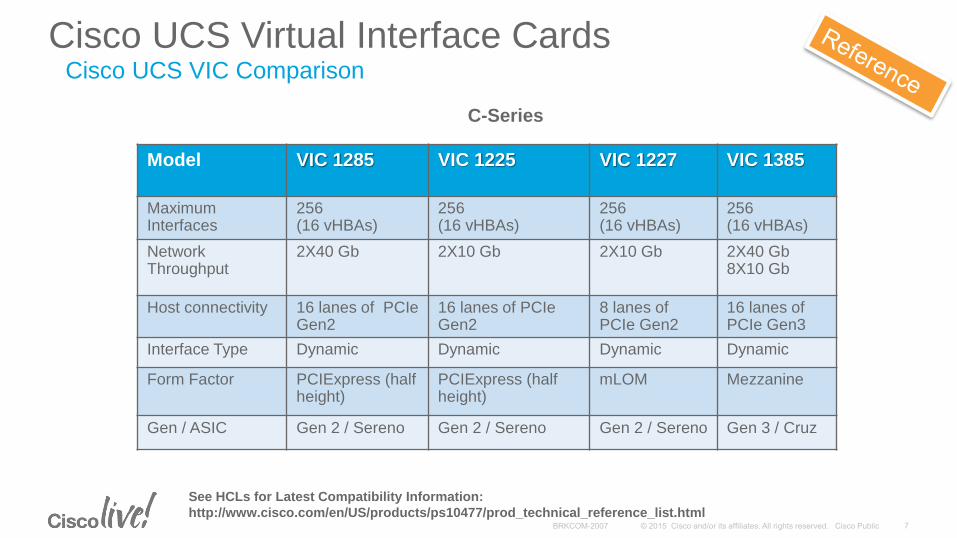
Cisco UCS Virtual Interface Cards
Model VIC 1285 VIC 1225 VIC 1227 VIC 1385
Maximum Interfaces
256(16 vHBAs)
256(16 vHBAs)
256(16 vHBAs)
256(16 vHBAs)
Network Throughput
2X40 Gb 2X10 Gb 2X10 Gb 2X40 Gb8X10 Gb
Host connectivity 16 lanes of PCIe Gen2
16 lanes of PCIe Gen2
8 lanes of PCIe Gen2
16 lanes of PCIe Gen3
Interface Type Dynamic Dynamic Dynamic Dynamic
Form Factor PCIExpress (half height)
PCIExpress (half height)
mLOM Mezzanine
Gen / ASIC Gen 2 / Sereno Gen 2 / Sereno Gen 2 / Sereno Gen 3 / Cruz
See HCLs for Latest Compatibility Information:
http://www.cisco.com/en/US/products/ps10477/prod_technical_reference_list.html
C-Series
Cisco UCS VIC Comparison
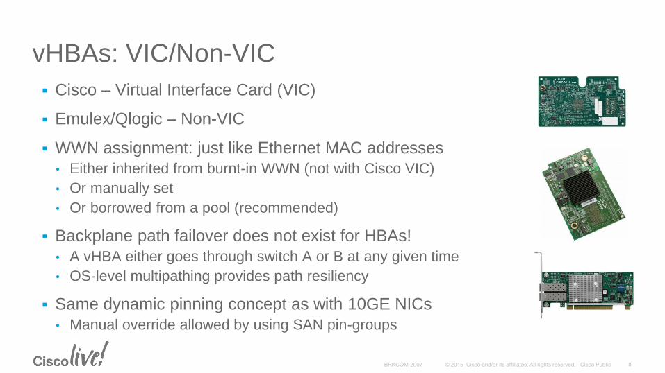
vHBAs: VIC/Non-VIC
Cisco – Virtual Interface Card (VIC)
Emulex/Qlogic – Non-VIC
WWN assignment: just like Ethernet MAC addresses
• Either inherited from burnt-in WWN (not with Cisco VIC)
• Or manually set
• Or borrowed from a pool (recommended)
Backplane path failover does not exist for HBAs!
• A vHBA either goes through switch A or B at any given time
• OS-level multipathing provides path resiliency
Same dynamic pinning concept as with 10GE NICs
• Manual override allowed by using SAN pin-groups
Fabric InterconnectsModes of Operation
N-Port Virtualization (NPV) Mode
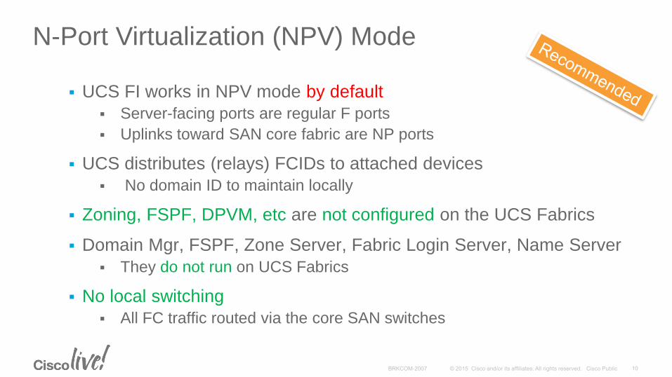
UCS FI works in NPV mode by default
Server-facing ports are regular F ports
Uplinks toward SAN core fabric are NP ports
UCS distributes (relays) FCIDs to attached devices
No domain ID to maintain locally
Zoning, FSPF, DPVM, etc are not configured on the UCS Fabrics
Domain Mgr, FSPF, Zone Server, Fabric Login Server, Name Server
They do not run on UCS Fabrics
No local switching
All FC traffic routed via the core SAN switches
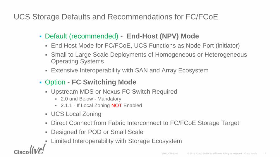
Default (recommended) - End-Host (NPV) Mode
End Host Mode for FC/FCoE, UCS Functions as Node Port (initiator)
Small to Large Scale Deployments of Homogeneous or Heterogeneous Operating Systems
Extensive Interoperability with SAN and Array Ecosystem
Option - FC Switching Mode
Upstream MDS or Nexus FC Switch Required 2.0 and Below - Mandatory
2.1.1 - If Local Zoning NOT Enabled
UCS Local Zoning
Direct Connect from Fabric Interconnect to FC/FCoE Storage Target
Designed for POD or Small Scale
Limited Interoperability with Storage Ecosystem
UCS Storage Defaults and Recommendations for FC/FCoE
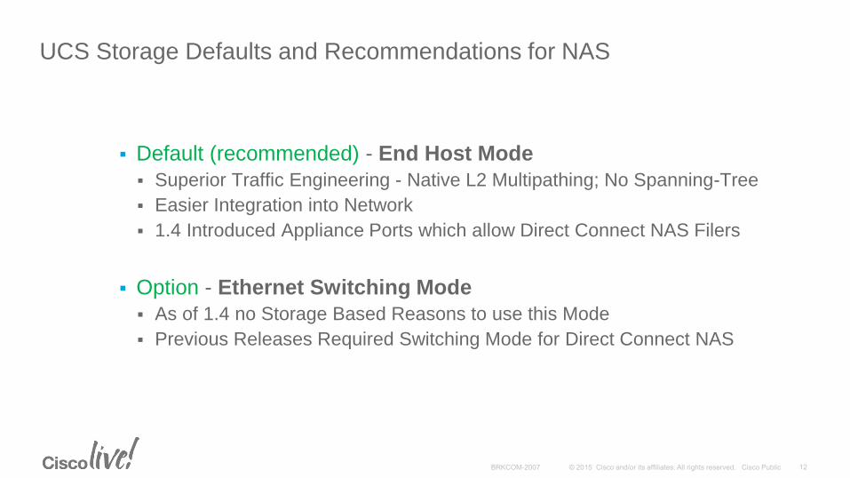
Default (recommended) - End Host Mode
Superior Traffic Engineering - Native L2 Multipathing; No Spanning-Tree
Easier Integration into Network
1.4 Introduced Appliance Ports which allow Direct Connect NAS Filers
Option - Ethernet Switching Mode
As of 1.4 no Storage Based Reasons to use this Mode
Previous Releases Required Switching Mode for Direct Connect NAS
UCS Storage Defaults and Recommendations for NAS
FC/FCoE Uplink ConnectivitySAN Uplinks, FCoE Multi-Hop,
Brocade, Hyper-V
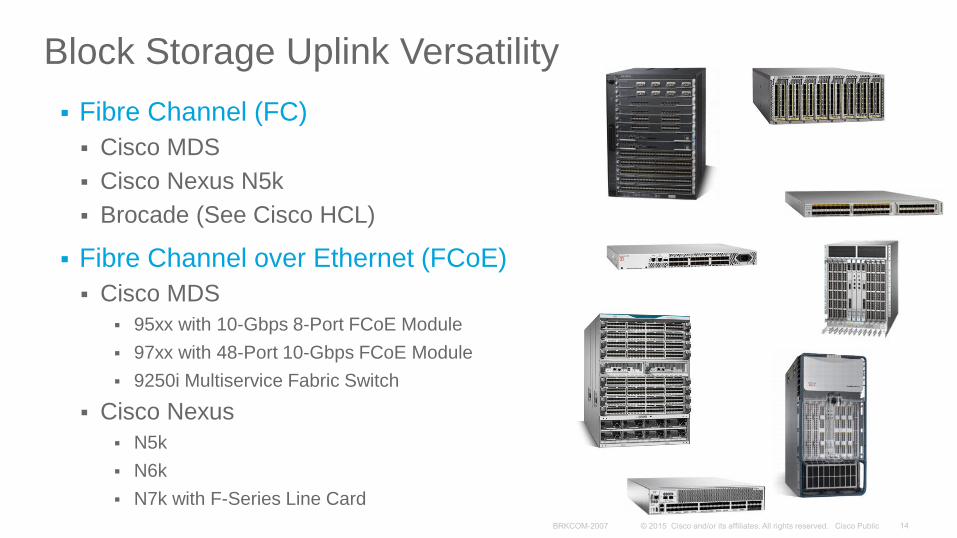
Block Storage Uplink Versatility
Fibre Channel (FC)
Cisco MDS
Cisco Nexus N5k
Brocade (See Cisco HCL)
Fibre Channel over Ethernet (FCoE)
Cisco MDS
95xx with 10-Gbps 8-Port FCoE Module
97xx with 48-Port 10-Gbps FCoE Module
9250i Multiservice Fabric Switch
Cisco Nexus
N5k
N6k
N7k with F-Series Line Card
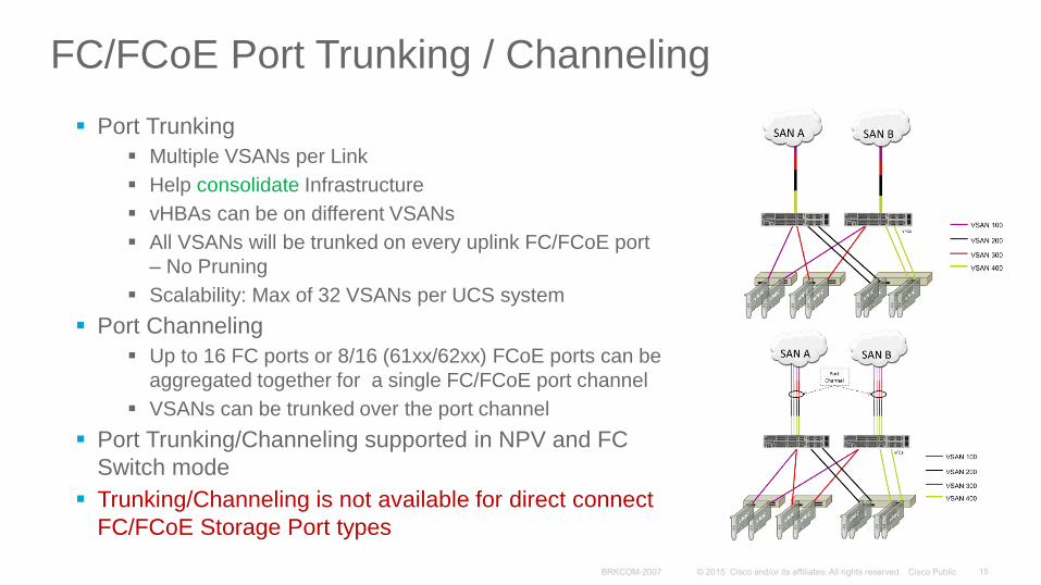
FC/FCoE Port Trunking / Channeling
Port Trunking
Multiple VSANs per Link
Help consolidate Infrastructure
vHBAs can be on different VSANs
All VSANs will be trunked on every uplink FC/FCoE port
– No Pruning
Scalability: Max of 32 VSANs per UCS system
Port Channeling
Up to 16 FC ports or 8/16 (61xx/62xx) FCoE ports can be
aggregated together for a single FC/FCoE port channel
VSANs can be trunked over the port channel
Port Trunking/Channeling supported in NPV and FC
Switch mode
Trunking/Channeling is not available for direct connect
FC/FCoE Storage Port types
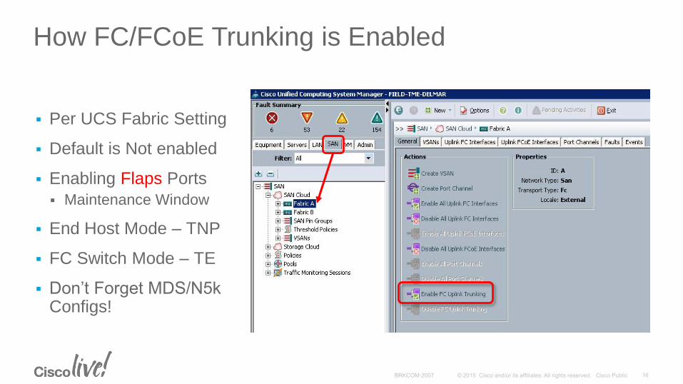
How FC/FCoE Trunking is Enabled
Per UCS Fabric Setting
Default is Not enabled
Enabling Flaps Ports
Maintenance Window
End Host Mode – TNP
FC Switch Mode – TE
Don’t Forget MDS/N5k Configs!
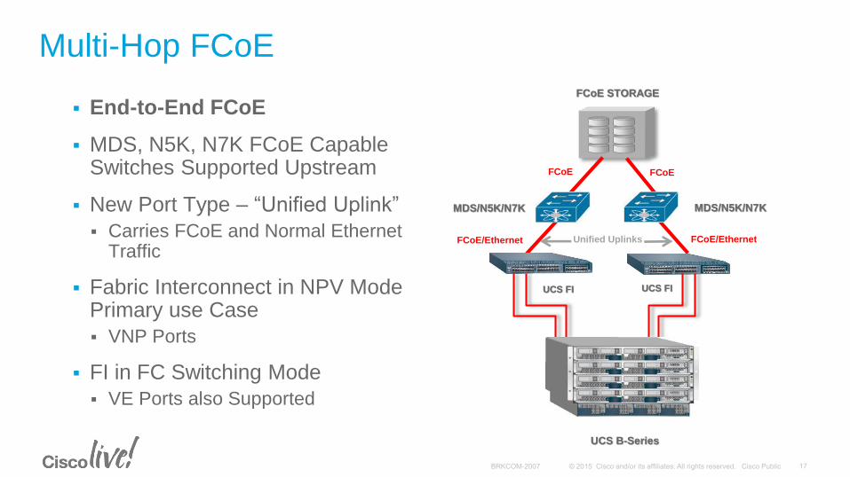
Multi-Hop FCoE
End-to-End FCoE
MDS, N5K, N7K FCoE Capable Switches Supported Upstream
New Port Type – “Unified Uplink”
Carries FCoE and Normal Ethernet Traffic
Fabric Interconnect in NPV Mode Primary use Case
VNP Ports
FI in FC Switching Mode
VE Ports also Supported
MDS/N5K/N7K
Unified Uplinks
UCS B-Series
UCS FI UCS FI
FCoE STORAGE
MDS/N5K/N7K
NPV/EHM
FCoE FCoE
FCoE/Ethernet FCoE/Ethernet
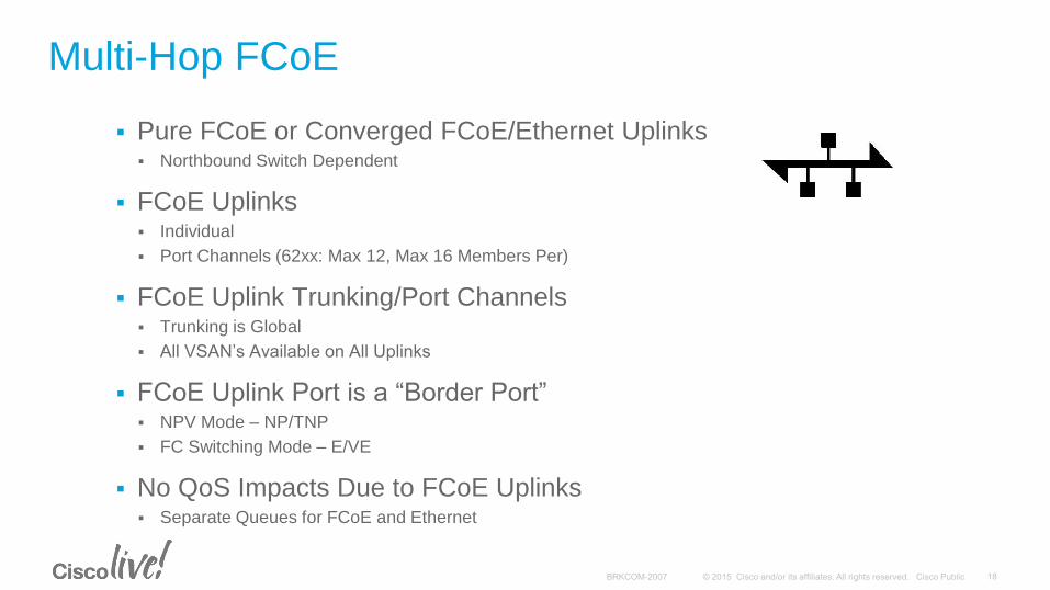
Multi-Hop FCoE
Pure FCoE or Converged FCoE/Ethernet Uplinks Northbound Switch Dependent
FCoE Uplinks Individual
Port Channels (62xx: Max 12, Max 16 Members Per)
FCoE Uplink Trunking/Port Channels Trunking is Global
All VSAN’s Available on All Uplinks
FCoE Uplink Port is a “Border Port” NPV Mode – NP/TNP
FC Switching Mode – E/VE
No QoS Impacts Due to FCoE Uplinks Separate Queues for FCoE and Ethernet
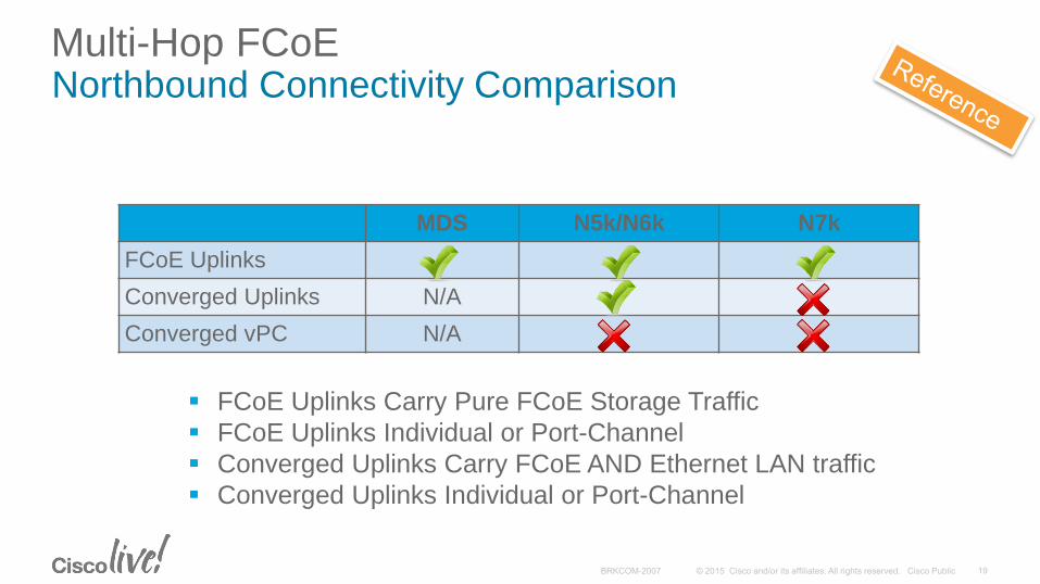
Multi-Hop FCoENorthbound Connectivity Comparison
MDS N5k/N6k N7k
FCoE Uplinks
Converged Uplinks N/A
Converged vPC N/A
FCoE Uplinks Carry Pure FCoE Storage Traffic
FCoE Uplinks Individual or Port-Channel
Converged Uplinks Carry FCoE AND Ethernet LAN traffic
Converged Uplinks Individual or Port-Channel
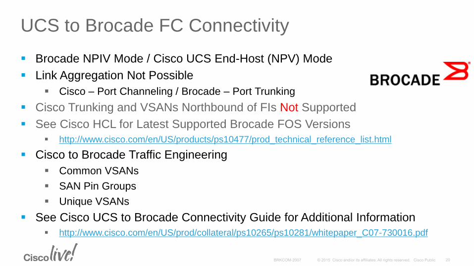
UCS to Brocade FC Connectivity
Brocade NPIV Mode / Cisco UCS End-Host (NPV) Mode
Link Aggregation Not Possible
Cisco – Port Channeling / Brocade – Port Trunking
Cisco Trunking and VSANs Northbound of FIs Not Supported
See Cisco HCL for Latest Supported Brocade FOS Versions
http://www.cisco.com/en/US/products/ps10477/prod_technical_reference_list.html
Cisco to Brocade Traffic Engineering
Common VSANs
SAN Pin Groups
Unique VSANs
See Cisco UCS to Brocade Connectivity Guide for Additional Information
http://www.cisco.com/en/US/prod/collateral/ps10265/ps10281/whitepaper_C07-730016.pdf
UCS to Brocade FC Connectivity
21 43
UCS
Fabric Interconnect - B
FC Uplink Ports
End Host Mode (NPV)
5
21 43
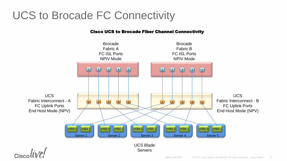
Brocade
Fabric B
FC ISL Ports
NPIV Mode
5
Cisco UCS to Brocade Fiber Channel Connectivity
21 43
UCS
Fabric Interconnect - A
FC Uplink Ports
End Host Mode (NPV)
5
21 43
Brocade
Fabric A
FC ISL Ports
NPIV Mode
5
UCS Blade
Servers
vHBA 0 vHBA 1
Server 1
vHBA 0 vHBA 1
Server 2
vHBA 0 vHBA 1
Server 3
vHBA 0 vHBA 1
Server 4
vHBA 0 vHBA 1
Server 5
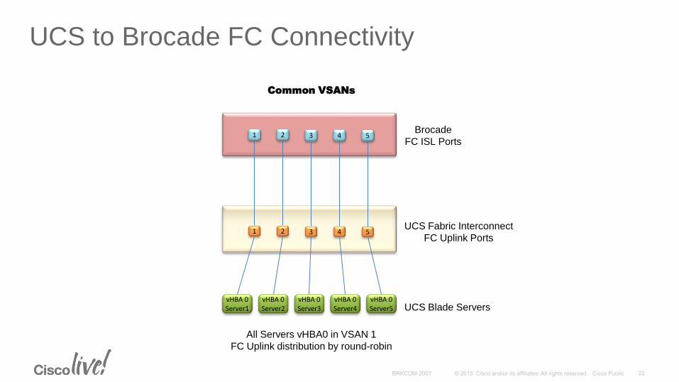
UCS to Brocade FC Connectivity
21 43UCS Fabric Interconnect
FC Uplink Ports5
21 43Brocade
FC ISL Ports5
UCS Blade ServersvHBA 0Server1
vHBA 0Server2
vHBA 0Server3
vHBA 0Server4
vHBA 0Server5
Common VSANs
All Servers vHBA0 in VSAN 1
FC Uplink distribution by round-robin
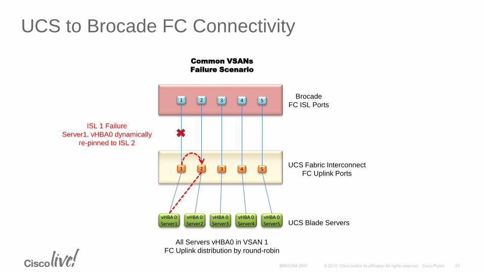
UCS to Brocade FC Connectivity
21 43UCS Fabric Interconnect
FC Uplink Ports5
21 43Brocade
FC ISL Ports5
UCS Blade ServersvHBA 0Server1
vHBA 0Server2
vHBA 0Server3
vHBA 0Server4
vHBA 0Server5
Common VSANs
Failure Scenario
All Servers vHBA0 in VSAN 1
FC Uplink distribution by round-robin
ISL 1 Failure
Server1, vHBA0 dynamically
re-pinned to ISL 2
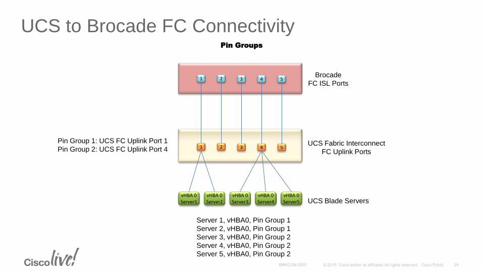
UCS to Brocade FC ConnectivityPin Groups
21 43UCS Fabric Interconnect
FC Uplink Ports5
21 43Brocade
FC ISL Ports5
UCS Blade ServersvHBA 0Server1
vHBA 0Server2
vHBA 0Server3
vHBA 0Server4
vHBA 0Server5
Server 1, vHBA0, Pin Group 1
Server 2, vHBA0, Pin Group 1
Server 3, vHBA0, Pin Group 2
Server 4, vHBA0, Pin Group 2
Server 5, vHBA0, Pin Group 2
Pin Group 1: UCS FC Uplink Port 1
Pin Group 2: UCS FC Uplink Port 4
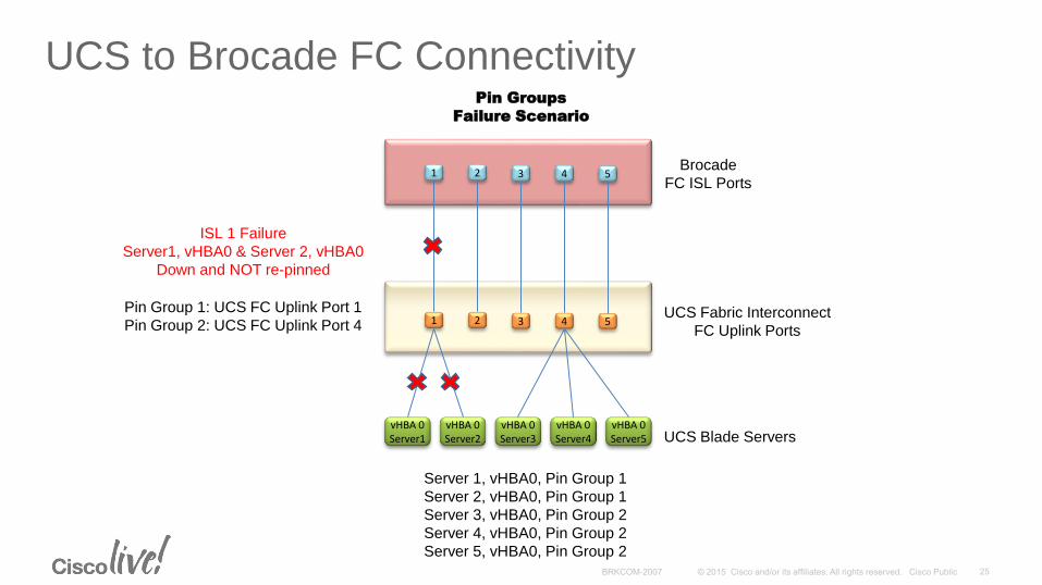
UCS to Brocade FC Connectivity
21 43UCS Fabric Interconnect
FC Uplink Ports5
21 43Brocade
FC ISL Ports5
UCS Blade ServersvHBA 0Server1
vHBA 0Server2
vHBA 0Server3
vHBA 0Server4
vHBA 0Server5
Pin Groups
Failure Scenario
Server 1, vHBA0, Pin Group 1
Server 2, vHBA0, Pin Group 1
Server 3, vHBA0, Pin Group 2
Server 4, vHBA0, Pin Group 2
Server 5, vHBA0, Pin Group 2
Pin Group 1: UCS FC Uplink Port 1
Pin Group 2: UCS FC Uplink Port 4
ISL 1 Failure
Server1, vHBA0 & Server 2, vHBA0
Down and NOT re-pinned
UCS to Brocade FC Connectivity
21 43UCS Fabric Interconnect
FC Uplink Ports5
21 43Brocade
FC ISL Ports5
UCS Blade ServersvHBA 0Server1
vHBA 0Server2
vHBA 0Server3
vHBA 0Server4
vHBA 0Server5
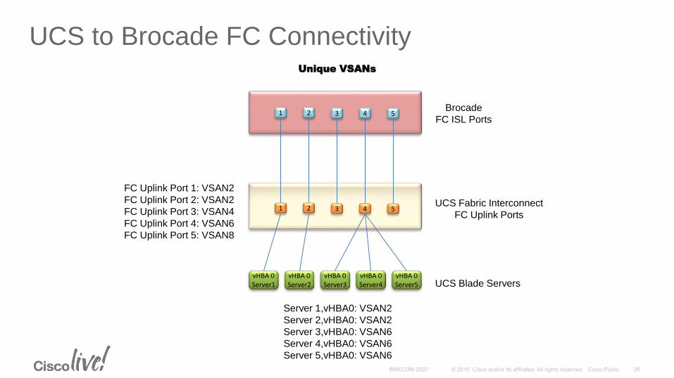
Unique VSANs
Server 1,vHBA0: VSAN2
Server 2,vHBA0: VSAN2
Server 3,vHBA0: VSAN6
Server 4,vHBA0: VSAN6
Server 5,vHBA0: VSAN6
FC Uplink Port 1: VSAN2
FC Uplink Port 2: VSAN2
FC Uplink Port 3: VSAN4
FC Uplink Port 4: VSAN6
FC Uplink Port 5: VSAN8
UCS to Brocade FC Connectivity
21 43UCS Fabric Interconnect
FC Uplink Ports5
21 43Brocade
FC ISL Ports5
UCS Blade ServersvHBA 0Server1
vHBA 0Server2
vHBA 0Server3
vHBA 0Server4
vHBA 0Server5
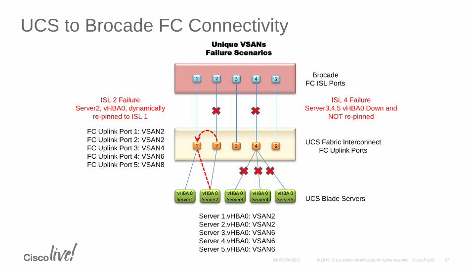
Unique VSANs
Failure Scenarios
FC Uplink Port 1: VSAN2
FC Uplink Port 2: VSAN2
FC Uplink Port 3: VSAN4
FC Uplink Port 4: VSAN6
FC Uplink Port 5: VSAN8
Server 1,vHBA0: VSAN2
Server 2,vHBA0: VSAN2
Server 3,vHBA0: VSAN6
Server 4,vHBA0: VSAN6
Server 5,vHBA0: VSAN6
ISL 2 Failure
Server2, vHBA0, dynamically
re-pinned to ISL 1
ISL 4 Failure
Server3,4,5 vHBA0 Down and
NOT re-pinned
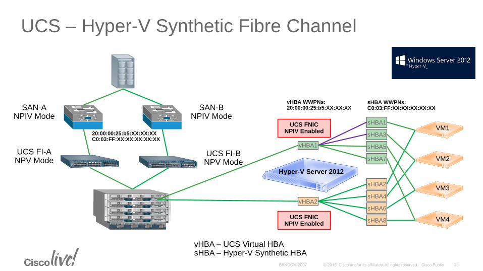
UCS – Hyper-V Synthetic Fibre Channel
SAN-ANPIV Mode
UCS FI-ANPV Mode
vHBA – UCS Virtual HBAsHBA – Hyper-V Synthetic HBA
sHBA1
vHBA1
vHBA2
sHBA3
sHBA5
sHBA7
sHBA2
sHBA4
sHBA6
sHBA8
Hyper-V Server 2012
VM1
VM2
VM3
VM4
UCS FNIC NPIV Enabled
SAN-BNPIV Mode
UCS FI-BNPV Mode
sHBA WWPNs: C0:03:FF:XX:XX:XX:XX:XX
vHBA WWPNs: 20:00:00:25:b5:XX:XX:XX
20:00:00:25:b5:XX:XX:XXC0:03:FF:XX:XX:XX:XX:XX
UCS FNIC NPIV Enabled
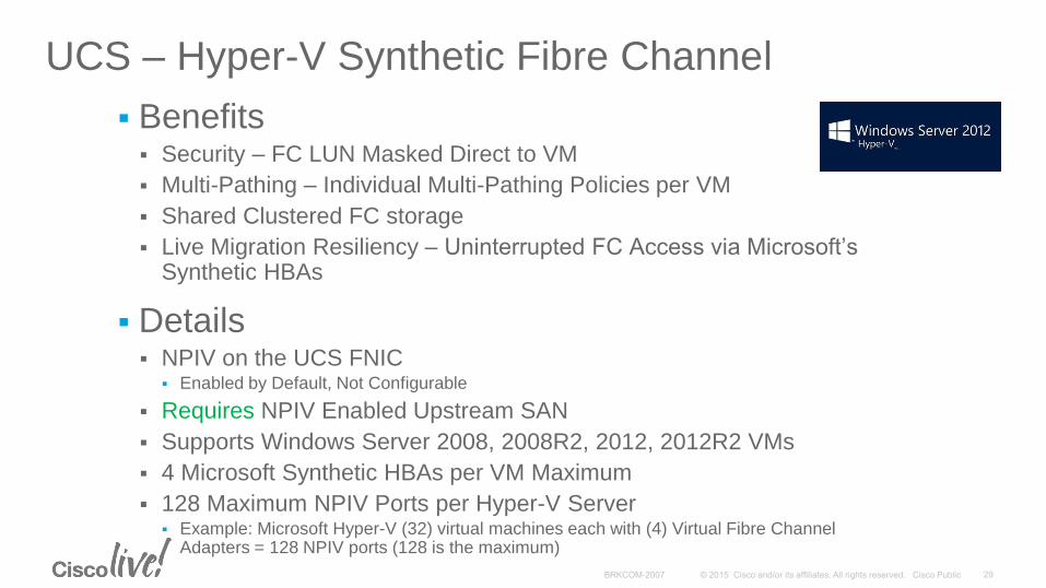
UCS – Hyper-V Synthetic Fibre Channel
Benefits Security – FC LUN Masked Direct to VM
Multi-Pathing – Individual Multi-Pathing Policies per VM
Shared Clustered FC storage
Live Migration Resiliency – Uninterrupted FC Access via Microsoft’s Synthetic HBAs
Details NPIV on the UCS FNIC
Enabled by Default, Not Configurable
Requires NPIV Enabled Upstream SAN
Supports Windows Server 2008, 2008R2, 2012, 2012R2 VMs
4 Microsoft Synthetic HBAs per VM Maximum
128 Maximum NPIV Ports per Hyper-V Server Example: Microsoft Hyper-V (32) virtual machines each with (4) Virtual Fibre Channel
Adapters = 128 NPIV ports (128 is the maximum)
UCS – Hyper-V Synthetic Fibre Channel
Caveats Not supported with UCS Local Zoning
No Persistent Binding
No Boot from SAN from VM via Microsoft Synthetic FC Adapters
Uplink Connectivity Caveats Enhanced Zoning
Not Currently Supported (In FC Switching Mode)
Will Result in Merge Failure
Enhanced Device-Alias / Inter-VSAN-Routing (IVR)
Not Supported (In FC Switching Mode)
FC to FCoE Bridging
Supported (Example: FI to N5k – FC, N5k to Northbound – FCoE)
Default VSAN 1
Global VSAN – Exists on UCS Fabric A and Fabric B
Best Practice not to use as General VSAN
Changing Default VSAN 1 associated FCoE VLAN ID Will Cause Global VSAN Disruption
External SAN Management Software N5K MIBs are all Exposed but READ ONLY
6xxx can be added to DCNM (Upstream Zoning) but the Manageability is Limited
Direct Connectivity of StoragePort Types, Local Zoning
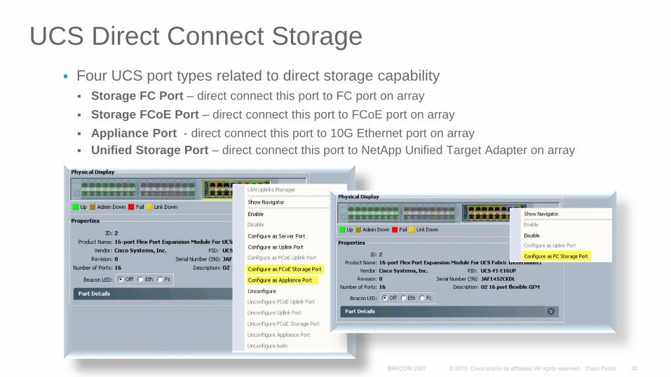
Four UCS port types related to direct storage capability
Storage FC Port – direct connect this port to FC port on array
Storage FCoE Port – direct connect this port to FCoE port on array
Appliance Port - direct connect this port to 10G Ethernet port on array
Unified Storage Port – direct connect this port to NetApp Unified Target Adapter on array
UCS Direct Connect Storage
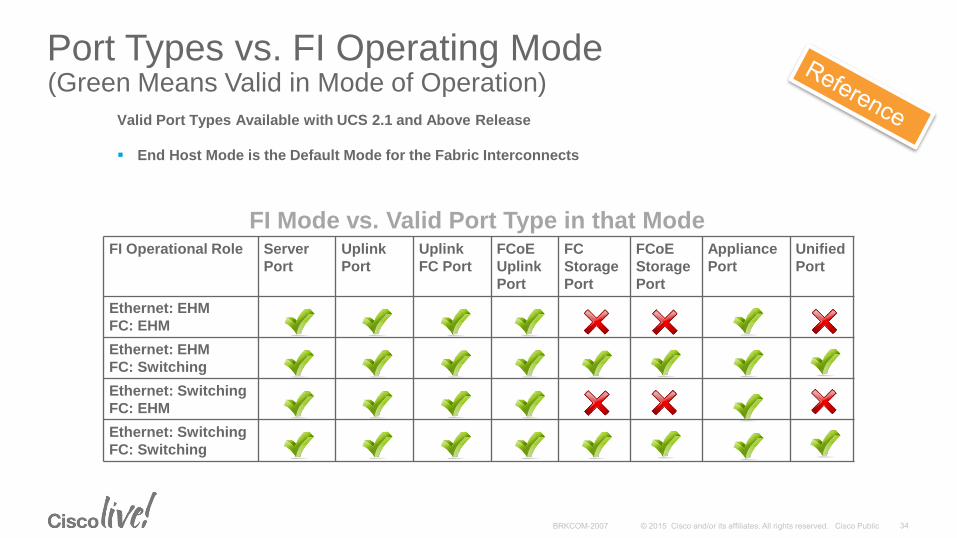
Port Types vs. FI Operating Mode (Green Means Valid in Mode of Operation)
FI Operational Role Server
Port
Uplink
Port
Uplink
FC Port
FCoE
Uplink
Port
FC
Storage
Port
FCoE
Storage
Port
Appliance
Port
Unified
Port
Ethernet: EHM
FC: EHM
Ethernet: EHM
FC: Switching
Ethernet: Switching
FC: EHM
Ethernet: Switching
FC: Switching
FI Mode vs. Valid Port Type in that Mode
Valid Port Types Available with UCS 2.1 and Above Release
End Host Mode is the Default Mode for the Fabric Interconnects
Local Zoning OR Upstream Zoning
UCS Configured in FC Switch Mode
Ethernet and FC Switching modes are Independent
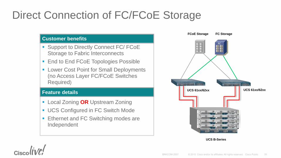
Support to Directly Connect FC/ FCoE Storage to Fabric Interconnects
End to End FCoE Topologies Possible
Lower Cost Point for Small Deployments (no Access Layer FC/FCoE Switches Required)
Customer benefits
Feature details
FCoE Storage FC Storage
Direct Connection of FC/FCoE Storage
UCS B-Series
UCS 61xx/62xx UCS 61xx/62xx
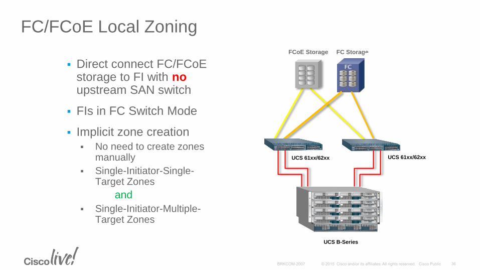
FC/FCoE Local Zoning
Direct connect FC/FCoE storage to FI with noupstream SAN switch
FIs in FC Switch Mode
Implicit zone creation No need to create zones
manually
Single-Initiator-Single-Target Zones
and
Single-Initiator-Multiple-Target Zones
FCoE Storage FC Storage
UCS B-Series
UCS 61xx/62xx UCS 61xx/62xx
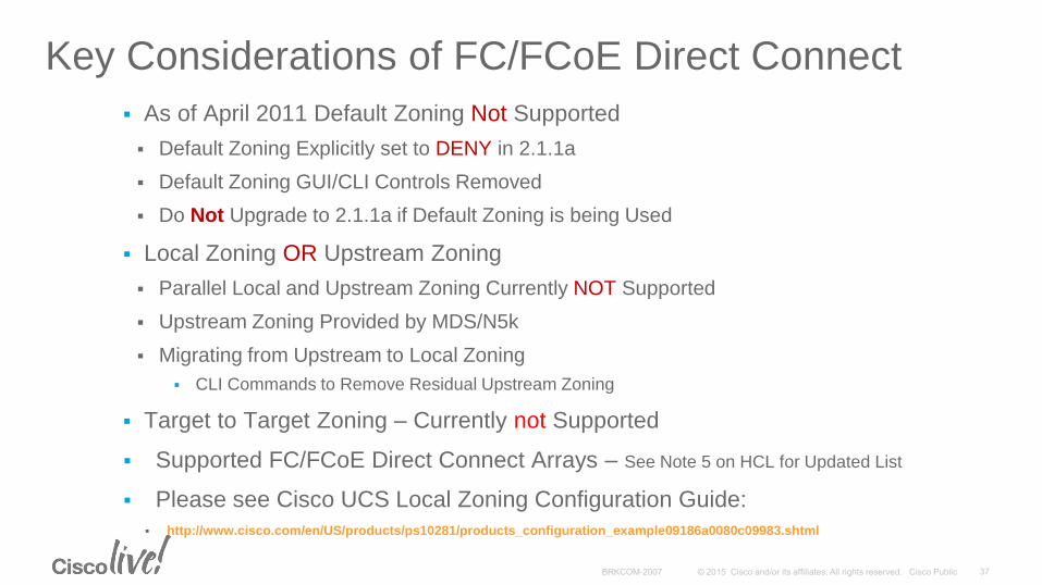
Key Considerations of FC/FCoE Direct Connect
As of April 2011 Default Zoning Not Supported
Default Zoning Explicitly set to DENY in 2.1.1a
Default Zoning GUI/CLI Controls Removed
Do Not Upgrade to 2.1.1a if Default Zoning is being Used
Local Zoning OR Upstream Zoning
Parallel Local and Upstream Zoning Currently NOT Supported
Upstream Zoning Provided by MDS/N5k
Migrating from Upstream to Local Zoning
CLI Commands to Remove Residual Upstream Zoning
Target to Target Zoning – Currently not Supported
Supported FC/FCoE Direct Connect Arrays – See Note 5 on HCL for Updated List
Please see Cisco UCS Local Zoning Configuration Guide:
http://www.cisco.com/en/US/products/ps10281/products_configuration_example09186a0080c09983.shtml
IP-based StorageAppliance Ports, iSCSI
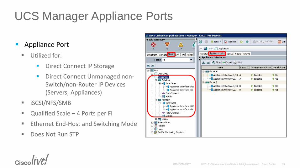
UCS Manager Appliance Ports
Appliance Port
Utilized for:
Direct Connect IP Storage
Direct Connect Unmanaged non-Switch/non-Router IP Devices (Servers, Appliances)
iSCSI/NFS/SMB
Qualified Scale – 4 Ports per FI
Ethernet End-Host and Switching Mode
Does Not Run STP
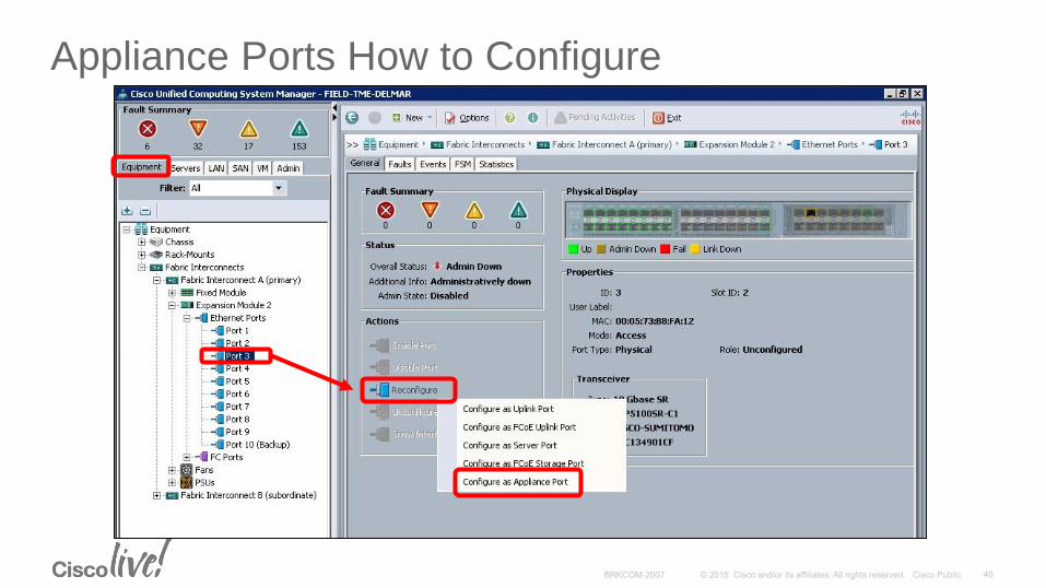
Appliance Ports How to Configure
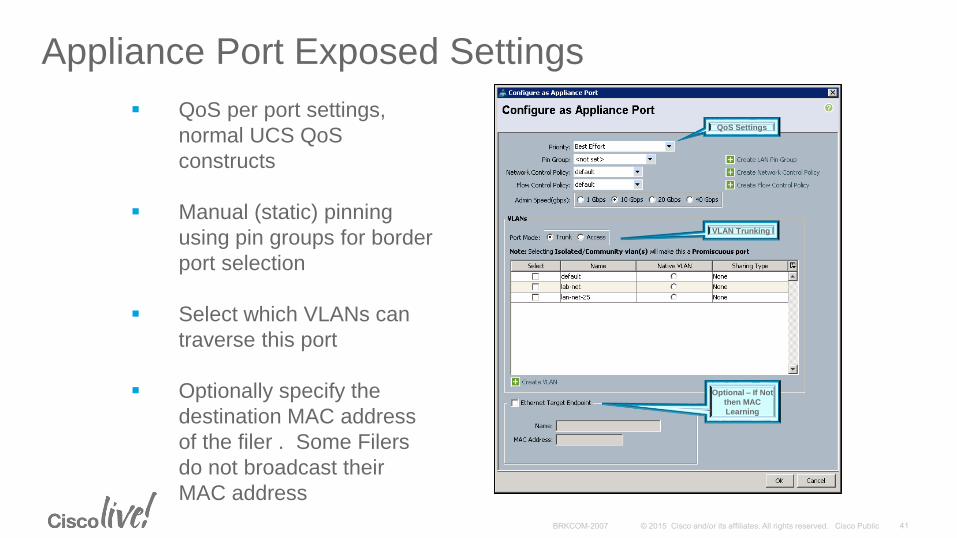
Appliance Port Exposed Settings
QoS per port settings,
normal UCS QoS
constructs
Manual (static) pinning
using pin groups for border
port selection
Select which VLANs can
traverse this port
Optionally specify the
destination MAC address
of the filer . Some Filers
do not broadcast their
MAC address
QoS Settings
VLAN Trunking
Optional – If Not
then MAC
Learning
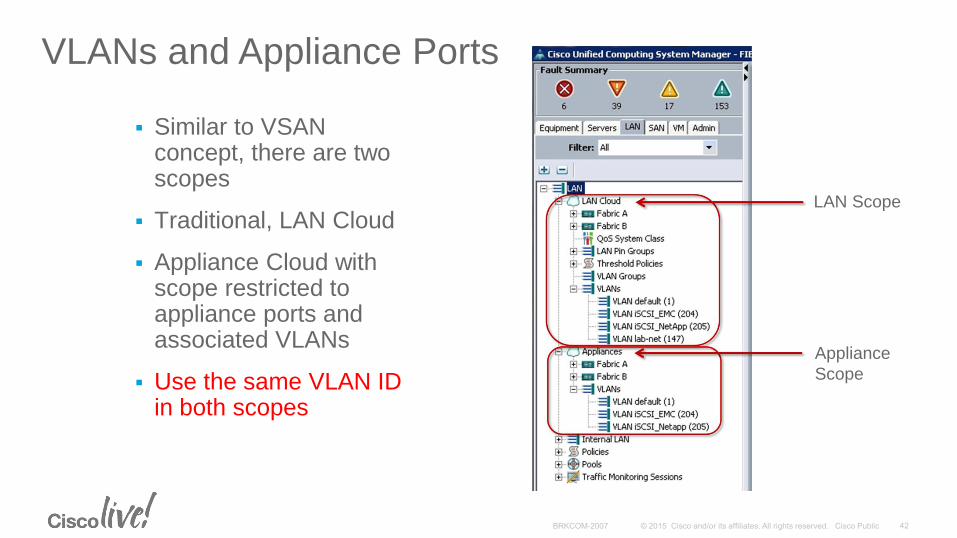
VLANs and Appliance Ports
Similar to VSAN concept, there are two scopes
Traditional, LAN Cloud
Appliance Cloud with scope restricted to appliance ports and associated VLANs
Use the same VLAN ID in both scopes
LAN Scope
Appliance
Scope
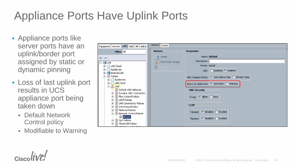
Appliance Ports Have Uplink Ports
Appliance ports like server ports have an uplink/border port assigned by static or dynamic pinning
Loss of last uplink port results in UCS appliance port being taken down
Default Network Control policy
Modifiable to Warning
iSCSI Feature Overview
Primary purpose is to support booting via iSCSI
UCS manager represents an iSCSI device in the model and GUI
Object called an “iSCSI vNIC” is created as a child object to the parent vNIC
CHAP / Mutual-CHAP Security
Initiator Authentication (CHAP), Target Authentication (M-CHAP)
Password (CHAP Secret) 12-16 Characters, $ = ? Invalid
iSCSI Failover and Redundancy
MPIO / Host Multi-Pathing Drivers Similar to FC – No Network Link Aggregation
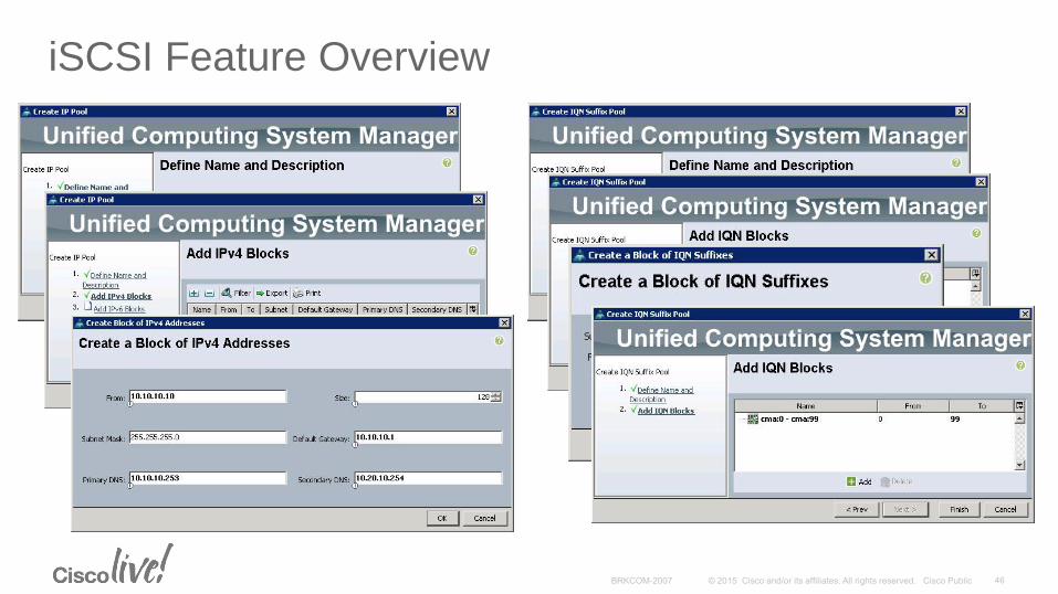
iSCSI Feature Overview
Pools (IP/IQN) and Policies to support iSCSI vNIC attributes
IP Assignment
DHCP
Static
Pools
IQN Assignment
Manual
Pools
Per vNIC
Per Service Profile (Single IQN) – Recommended per RFC3720
iSCSI Feature Overview
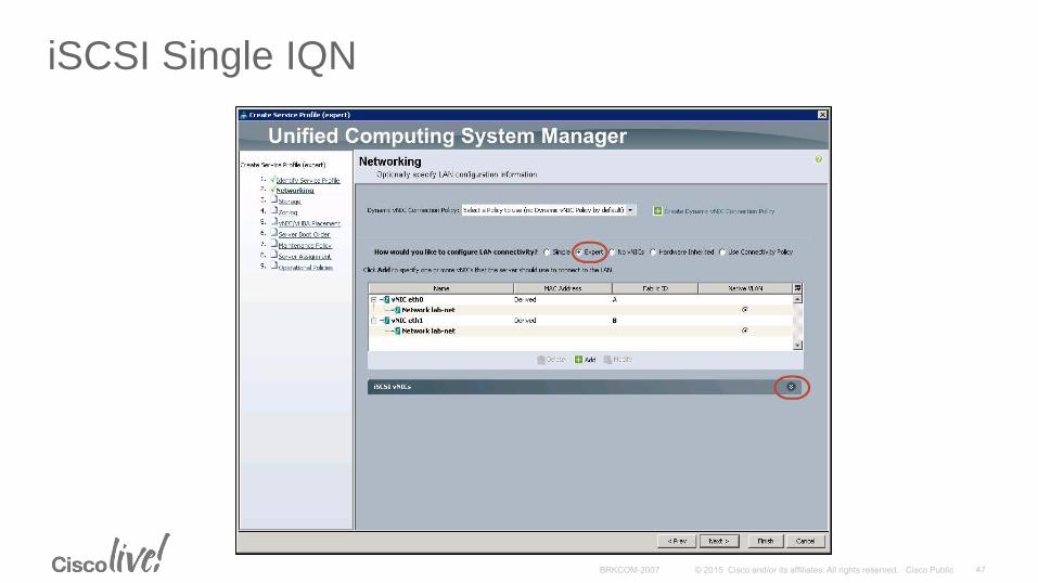
iSCSI Single IQN
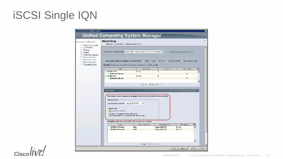
iSCSI Single IQN
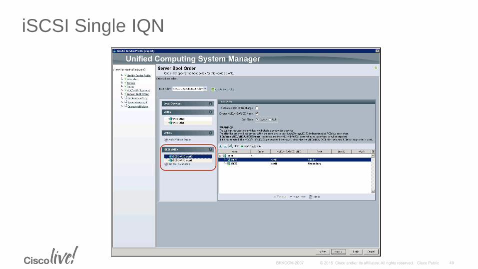
iSCSI Single IQN
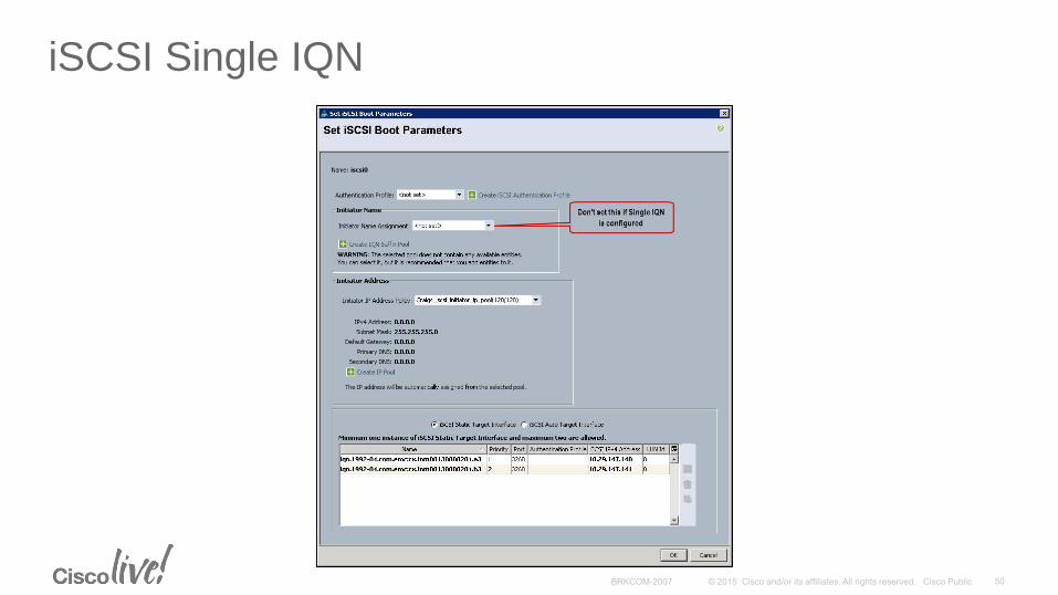
iSCSI Single IQN
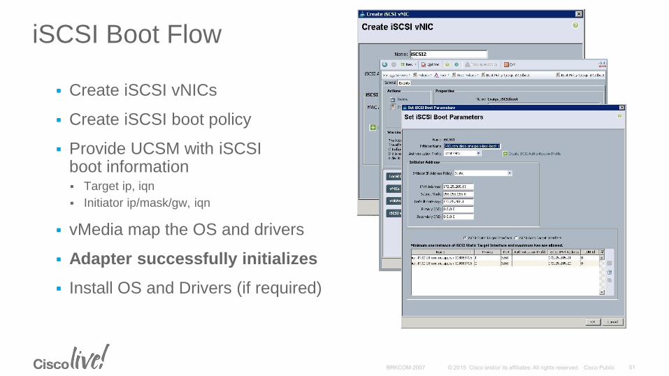
iSCSI Boot Flow
Create iSCSI vNICs
Create iSCSI boot policy
Provide UCSM with iSCSI boot information Target ip, iqn
Initiator ip/mask/gw, iqn
vMedia map the OS and drivers
Adapter successfully initializes
Install OS and Drivers (if required)
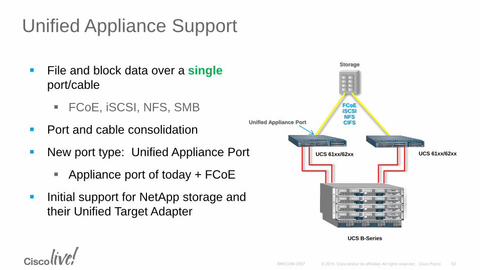
Unified Appliance Support
File and block data over a single
port/cable
FCoE, iSCSI, NFS, SMB
Port and cable consolidation
New port type: Unified Appliance Port
Appliance port of today + FCoE
Initial support for NetApp storage and
their Unified Target Adapter
Storage
FCoEiSCSINFSCIFSUnified Appliance Port
UCS B-Series
UCS 61xx/62xx UCS 61xx/62xx
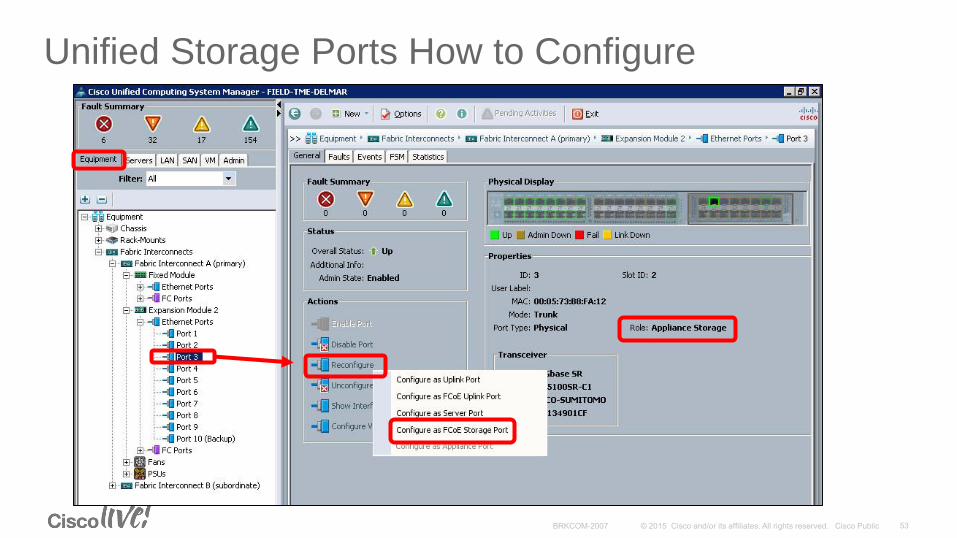
Unified Storage Ports How to Configure
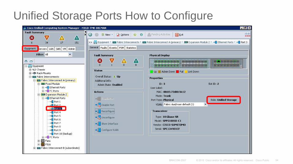
Unified Storage Ports How to Configure
Storage AccelerationPCIe Flash Storage
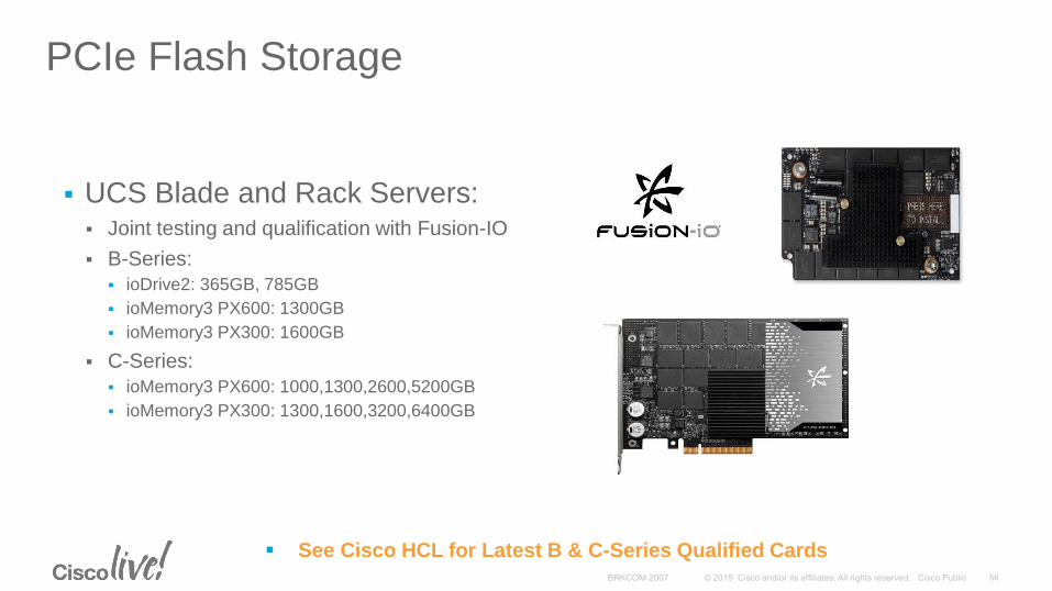
PCIe Flash Storage
UCS Blade and Rack Servers: Joint testing and qualification with Fusion-IO
B-Series:
ioDrive2: 365GB, 785GB
ioMemory3 PX600: 1300GB
ioMemory3 PX300: 1600GB
C-Series:
ioMemory3 PX600: 1000,1300,2600,5200GB
ioMemory3 PX300: 1300,1600,3200,6400GB
See Cisco HCL for Latest B & C-Series Qualified Cards
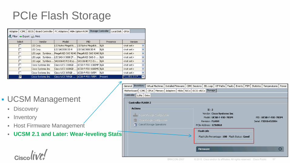
PCIe Flash Storage
UCSM Management Discovery
Inventory
Host Firmware Management
UCSM 2.1 and Later: Wear-leveling Stats
UCS Mini
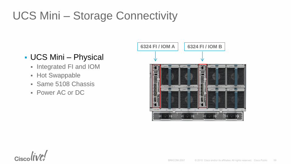
UCS Mini – Storage Connectivity
UCS Mini – Physical Integrated FI and IOM
Hot Swappable
Same 5108 Chassis
Power AC or DC
6324 FI / IOM A 6324 FI / IOM B
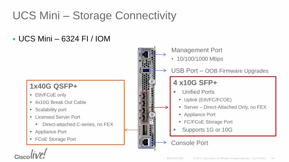
UCS Mini – Storage Connectivity
UCS Mini – 6324 FI / IOM
4 x10G SFP+
Unified Ports
Uplink (Eth/FC/FCOE)
Server – Direct-Attached Only, no FEX
Appliance Port
FC/FCoE Storage Port
Supports 1G or 10G
1x40G QSFP+ Eth/FCoE only
4x10G Break Out Cable
Scalability port
Licensed Server Port
Direct-attached C-series, no FEX
Appliance Port
FCoE Storage Port
Management Port
• 10/100/1000 Mbps
USB Port – OOB Firmware Upgrades
Console Port
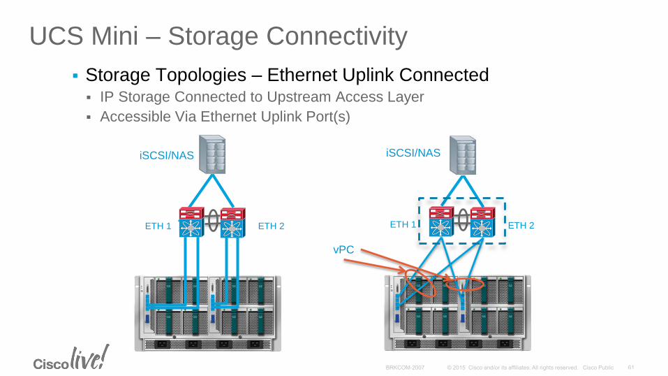
UCS Mini – Storage Connectivity
Storage Topologies – Ethernet Uplink Connected IP Storage Connected to Upstream Access Layer
Accessible Via Ethernet Uplink Port(s)
ETH 1 ETH 2
iSCSI/NAS
ETH 1 ETH 2
iSCSI/NAS
vPC
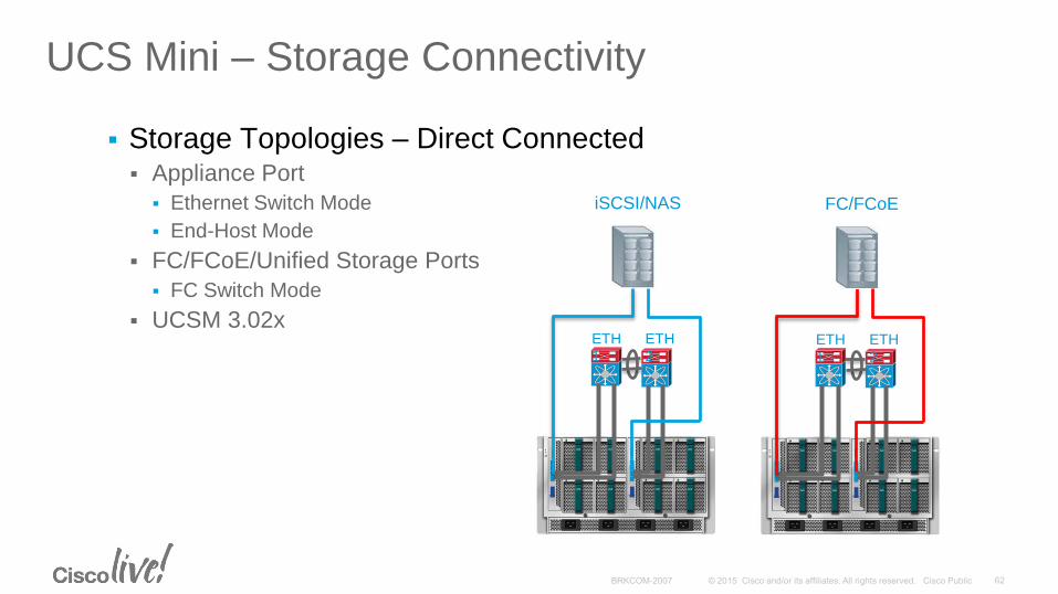
UCS Mini – Storage Connectivity
Storage Topologies – Direct Connected Appliance Port
Ethernet Switch Mode
End-Host Mode
FC/FCoE/Unified Storage Ports
FC Switch Mode
UCSM 3.02xETH
1
ETH
2
iSCSI/NAS
ETH
1
ETH
2
FC/FCoE
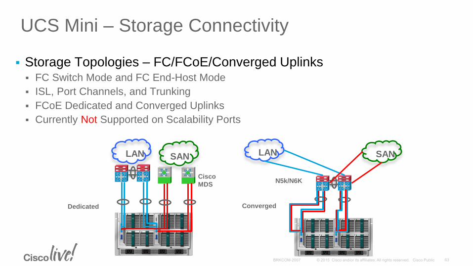
UCS Mini – Storage Connectivity
Storage Topologies – FC/FCoE/Converged Uplinks FC Switch Mode and FC End-Host Mode
ISL, Port Channels, and Trunking
FCoE Dedicated and Converged Uplinks
Currently Not Supported on Scalability Ports
LAN SAN
Cisco
MDS
LAN SAN
N5k/N6K
ConvergedDedicated
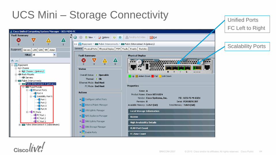
UCS Mini – Storage ConnectivityUnified Ports
FC Left to Right
Scalability Ports
New Miscellaneous
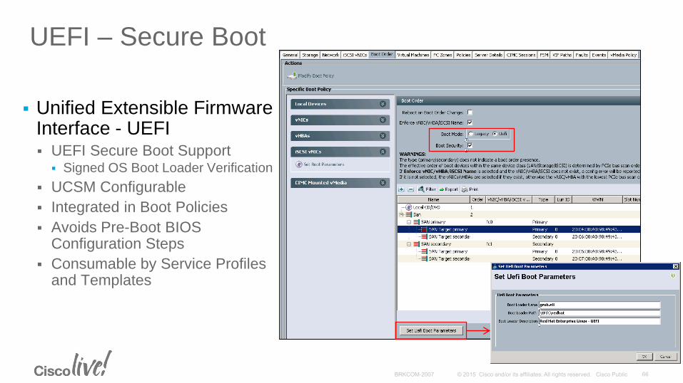
UEFI – Secure Boot
Unified Extensible Firmware Interface - UEFI UEFI Secure Boot Support
Signed OS Boot Loader Verification
UCSM Configurable
Integrated in Boot Policies
Avoids Pre-Boot BIOS Configuration Steps
Consumable by Service Profiles and Templates
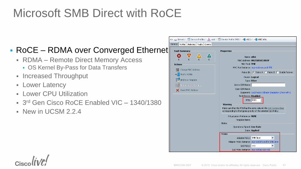
Microsoft SMB Direct with RoCE
RoCE – RDMA over Converged Ethernet RDMA – Remote Direct Memory Access
OS Kernel By-Pass for Data Transfers
Increased Throughput
Lower Latency
Lower CPU Utilization
3rd Gen Cisco RoCE Enabled VIC – 1340/1380
New in UCSM 2.2.4
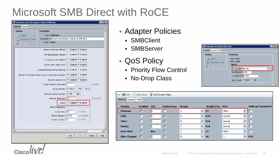
Microsoft SMB Direct with RoCE
Adapter Policies SMBClient
SMBServer
QoS Policy Priority Flow Control
No-Drop Class
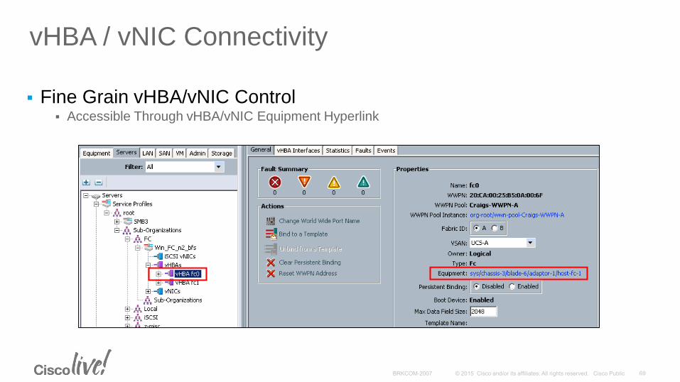
vHBA / vNIC Connectivity
Fine Grain vHBA/vNIC Control Accessible Through vHBA/vNIC Equipment Hyperlink
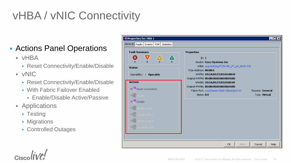
vHBA / vNIC Connectivity
Actions Panel Operations vHBA
Reset Connectivity/Enable/Disable
vNIC
Reset Connectivity/Enable/Disable
With Fabric Failover Enabled
Enable/Disable Active/Passive
Applications
Testing
Migrations
Controlled Outages
UCS C3000 High Density Server
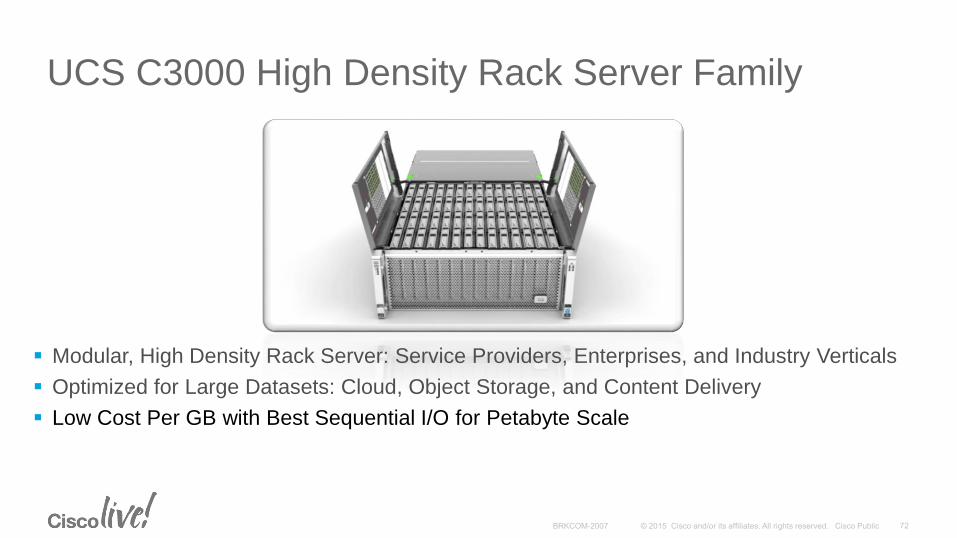
UCS C3000 High Density Rack Server Family
Modular, High Density Rack Server: Service Providers, Enterprises, and Industry Verticals
Optimized for Large Datasets: Cloud, Object Storage, and Content Delivery
Low Cost Per GB with Best Sequential I/O for Petabyte Scale
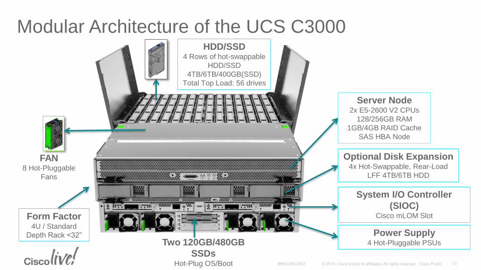
Modular Architecture of the UCS C3000HDD/SSD
4 Rows of hot-swappable
HDD/SSD
4TB/6TB/400GB(SSD)
Total Top Load: 56 drives
FAN8 Hot-Pluggable
Fans
Server Node2x E5-2600 V2 CPUs
128/256GB RAM
1GB/4GB RAID Cache
SAS HBA Node
Optional Disk Expansion4x Hot-Swappable, Rear-Load
LFF 4TB/6TB HDD
Two 120GB/480GB
SSDsHot-Plug OS/Boot
System I/O Controller
(SIOC)Cisco mLOM Slot
Power Supply4 Hot-Pluggable PSUs
Form Factor4U / Standard
Depth Rack <32”
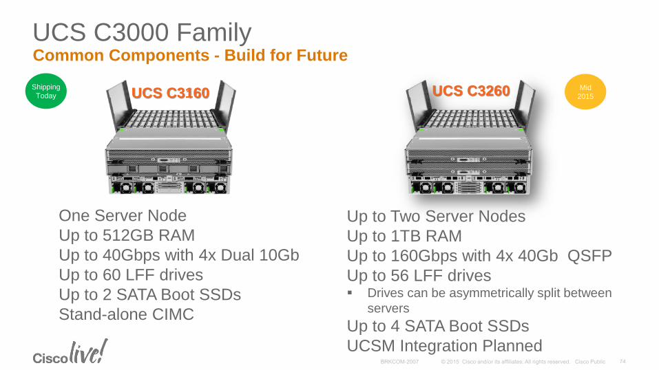
UCS C3000 FamilyCommon Components - Build for Future
UCS C3160 UCS C3260
One Server Node
Up to 512GB RAM
Up to 40Gbps with 4x Dual 10Gb
Up to 60 LFF drives
Up to 2 SATA Boot SSDs
Stand-alone CIMC
Up to Two Server Nodes
Up to 1TB RAM
Up to 160Gbps with 4x 40Gb QSFP
Up to 56 LFF drives Drives can be asymmetrically split between
servers
Up to 4 SATA Boot SSDs
UCSM Integration Planned
Shipping
TodayMid
2015
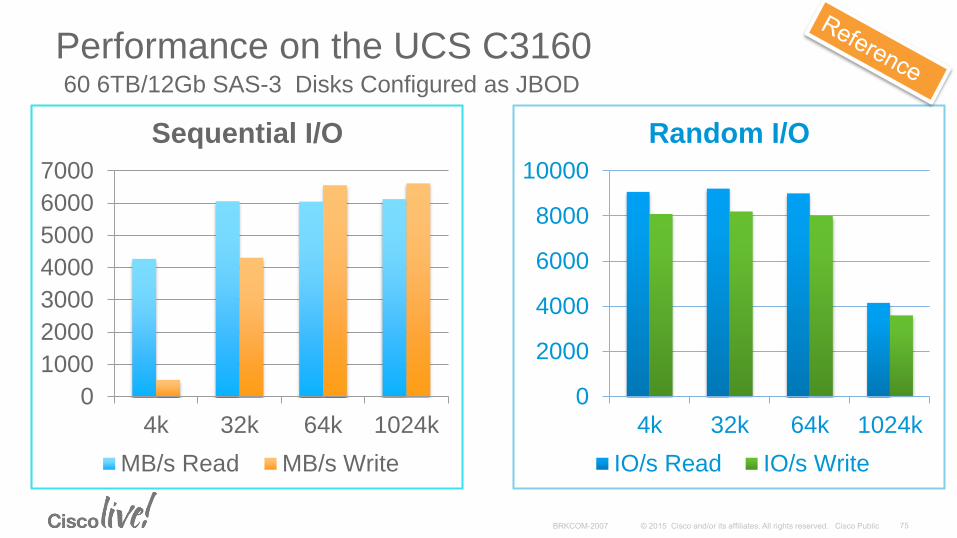
Performance on the UCS C3160
0
1000
2000
3000
4000
5000
6000
7000
4k 32k 64k 1024k
Sequential I/O
MB/s Read MB/s Write
0
2000
4000
6000
8000
10000
4k 32k 64k 1024k
Random I/O
IO/s Read IO/s Write
60 6TB/12Gb SAS-3 Disks Configured as JBOD
Storage Profiles
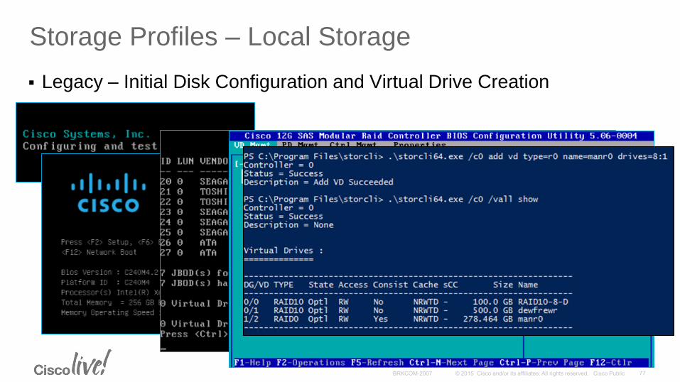
Storage Profiles – Local Storage
Legacy – Initial Disk Configuration and Virtual Drive Creation
Storage Profiles – Local Storage
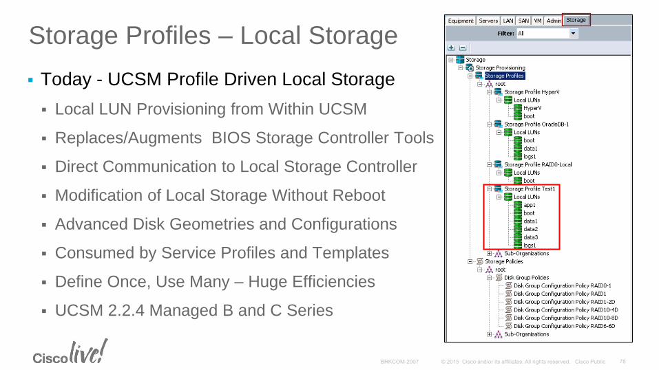
Today - UCSM Profile Driven Local Storage
Local LUN Provisioning from Within UCSM
Replaces/Augments BIOS Storage Controller Tools
Direct Communication to Local Storage Controller
Modification of Local Storage Without Reboot
Advanced Disk Geometries and Configurations
Consumed by Service Profiles and Templates
Define Once, Use Many – Huge Efficiencies
UCSM 2.2.4 Managed B and C Series
Storage Profiles – Local Storage
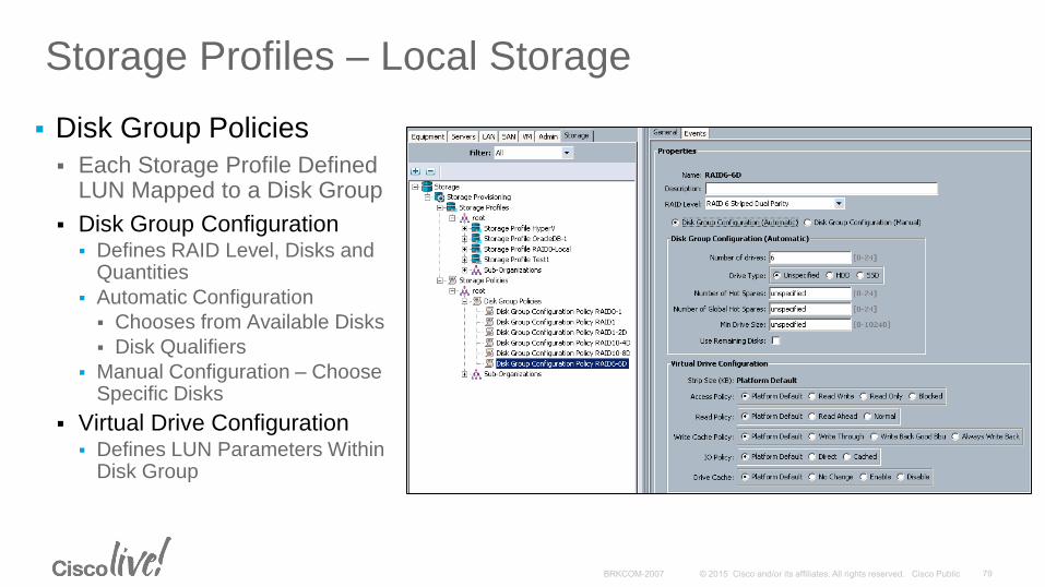
Disk Group Policies
Each Storage Profile Defined LUN Mapped to a Disk Group
Disk Group Configuration Defines RAID Level, Disks and
Quantities
Automatic Configuration
Chooses from Available Disks
Disk Qualifiers
Manual Configuration – Choose Specific Disks
Virtual Drive Configuration Defines LUN Parameters Within
Disk Group
Storage Profiles – Local Storage
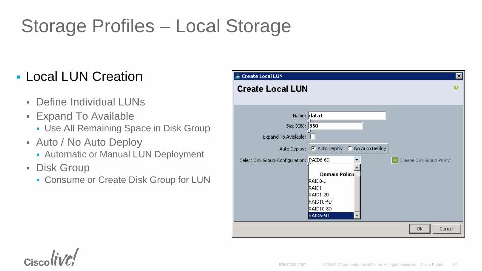
Local LUN Creation
Define Individual LUNs
Expand To Available Use All Remaining Space in Disk Group
Auto / No Auto Deploy Automatic or Manual LUN Deployment
Disk Group Consume or Create Disk Group for LUN
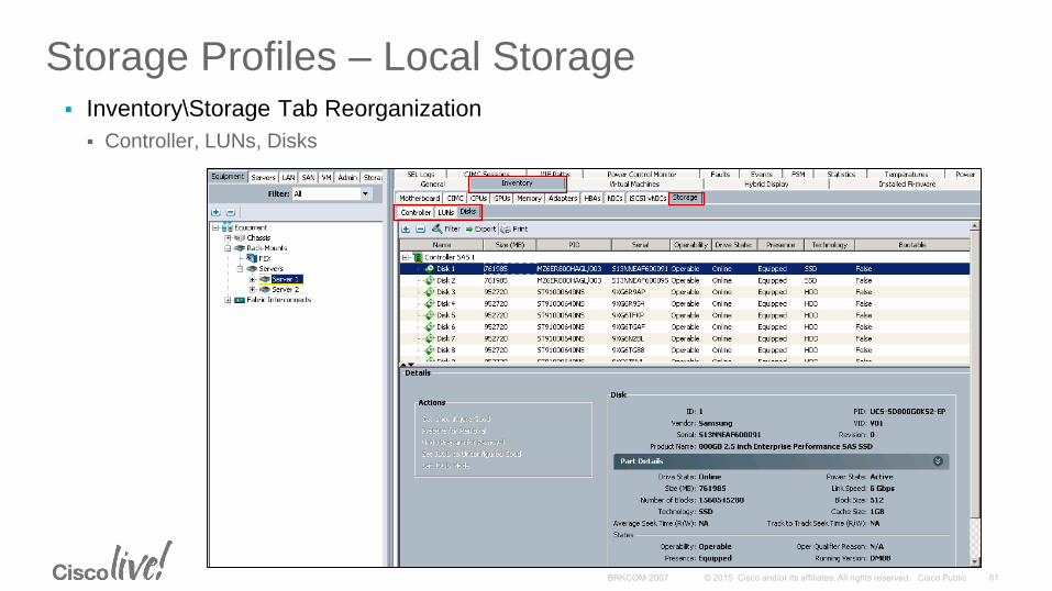
Storage Profiles – Local Storage Inventory\Storage Tab Reorganization
Controller, LUNs, Disks
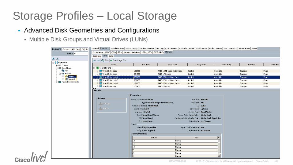
Storage Profiles – Local Storage Advanced Disk Geometries and Configurations
Multiple Disk Groups and Virtual Drives (LUNs)
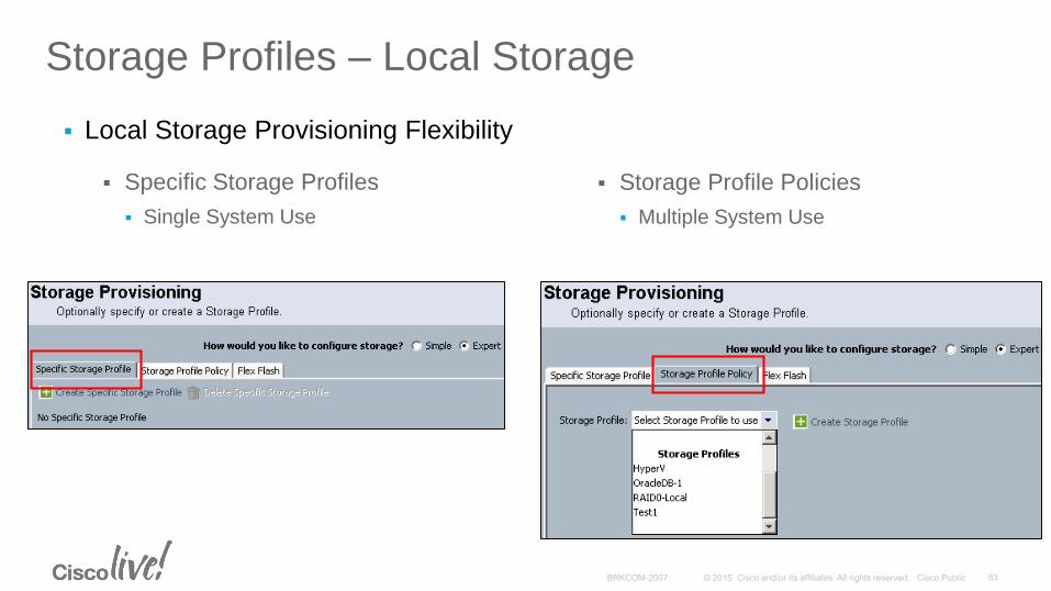
Storage Profiles – Local Storage
Local Storage Provisioning Flexibility
Specific Storage Profiles
Single System Use
Storage Profile Policies
Multiple System Use
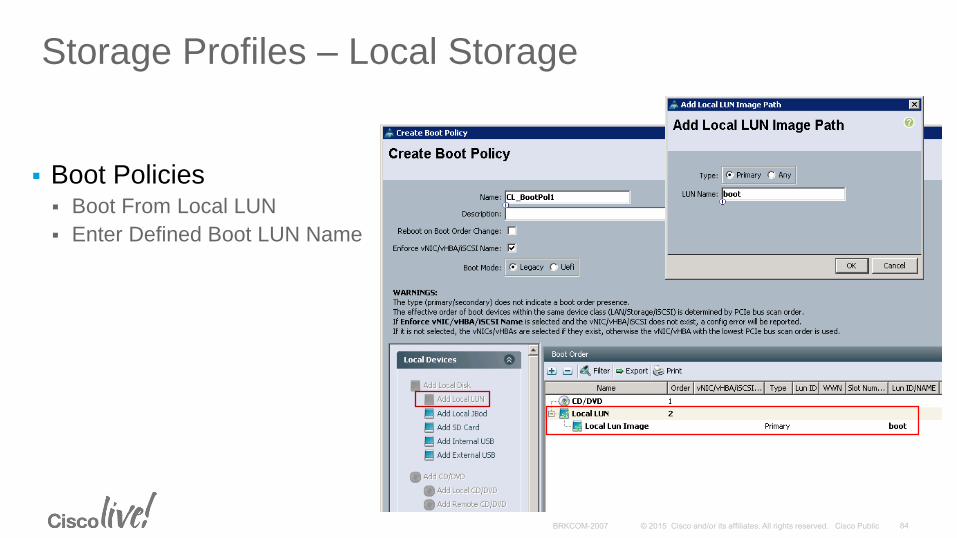
Storage Profiles – Local Storage
Boot Policies Boot From Local LUN
Enter Defined Boot LUN Name

M-Series
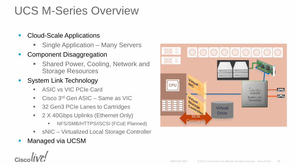
UCS M-Series Overview
Cloud-Scale Applications
Single Application – Many Servers
Component Disaggregation
Shared Power, Cooling, Network and Storage Resources
System Link Technology
ASIC vs VIC PCIe Card
Cisco 3rd Gen ASIC – Same as VIC
32 Gen3 PCIe Lanes to Cartridges
2 X 40Gbps Uplinks (Ethernet Only)
NFS/SMB/HTTPS/iSCSI (FCoE Planned)
sNIC – Virtualized Local Storage Controller
Managed via UCSM
Virtual
DriveSCSI
Commands
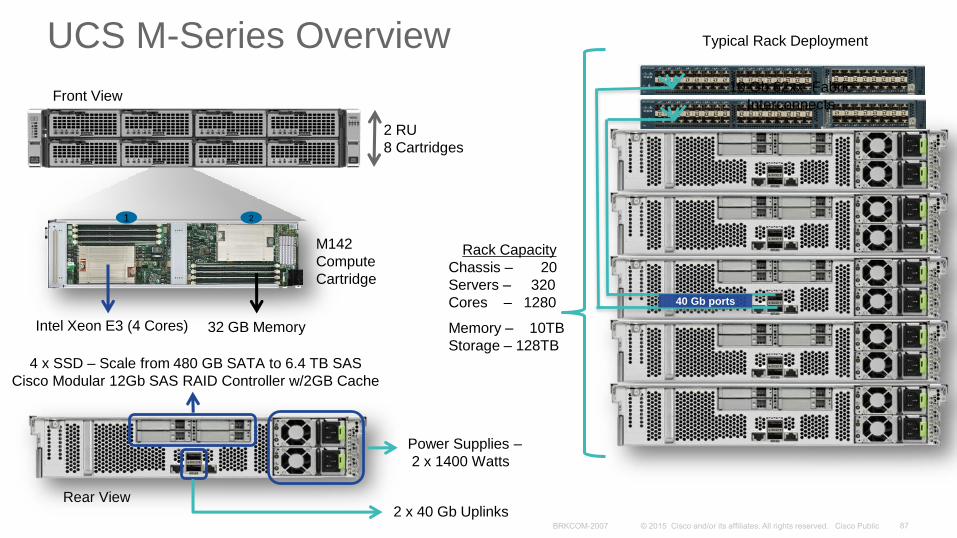
Typical Rack Deployment
Front View
M142
Compute
Cartridge
2 RU
8 Cartridges
Intel Xeon E3 (4 Cores) 32 GB Memory
1 2
Rear View
4 x SSD – Scale from 480 GB SATA to 6.4 TB SAS
Cisco Modular 12Gb SAS RAID Controller w/2GB Cache
Power Supplies –
2 x 1400 Watts
2 x 40 Gb Uplinks
Rack Capacity
Chassis – 20
Servers – 320
Cores – 1280
Memory – 10TB
Storage – 128TB
40 Gb ports
10 Gb 62xx Fabric
Interconnects
UCS M-Series Overview
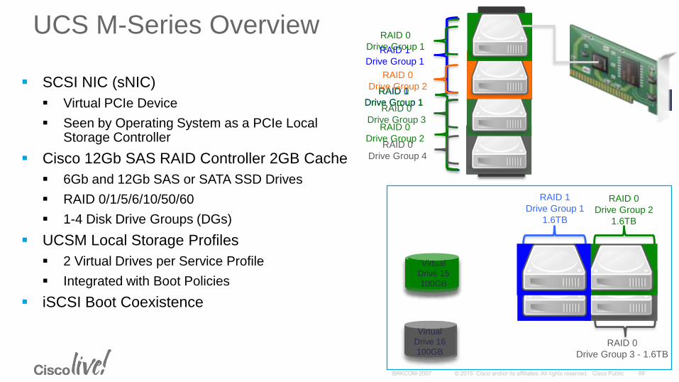
UCS M-Series Overview
SCSI NIC (sNIC)
Virtual PCIe Device
Seen by Operating System as a PCIe Local Storage Controller
Cisco 12Gb SAS RAID Controller 2GB Cache
6Gb and 12Gb SAS or SATA SSD Drives
RAID 0/1/5/6/10/50/60
1-4 Disk Drive Groups (DGs)
UCSM Local Storage Profiles
2 Virtual Drives per Service Profile
Integrated with Boot Policies
iSCSI Boot Coexistence
RAID 1
Drive Group 1
RAID 0
Drive Group 1
RAID 1
Drive Group 1
RAID 0
Drive Group 2
RAID 0
Drive Group 1
RAID 0
Drive Group 2
RAID 0
Drive Group 3
RAID 0
Drive Group 4
RAID 1
Drive Group 1
1.6TB
RAID 0
Drive Group 2
1.6TB
RAID 0
Drive Group 3 - 1.6TB
Virtual
Drive 18
100GB
Virtual
Drive 22
100B
Virtual
Drive 18
100GB
Virtual
Drive 19
100GB
Virtual
Drive 17
100GB
Virtual
Drive 0
200GB
Virtual
Drive 20
100GB
Virtual
Drive 23
100GB
Virtual
Drive 1
200GB
Virtual
Drive 16
100GB
Virtual
Drive 2
200GB
Virtual
Drive 3
200GB
Virtual
Drive 4
200GB
Virtual
Drive 5
200GB
Virtual
Drive 6
200GB
Virtual
Drive 7
200GB
Virtual
Drive 8
100GB
Virtual
Drive 9
100B
Virtual
Drive 10
100GB
Virtual
Drive 11
100GB
Virtual
Drive 12
100GB
Virtual
Drive 13
100GB
Virtual
Drive 14
100GB
Virtual
Drive 15
100GB
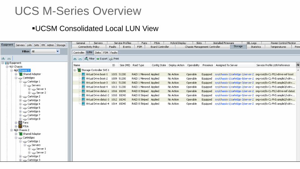
UCS M-Series Overview
UCSM Consolidated Local LUN View
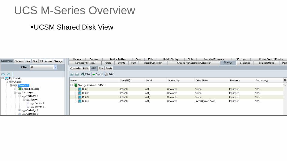
UCS M-Series Overview
UCSM Shared Disk View
Monitoring, Troubleshooting and Advanced CLI
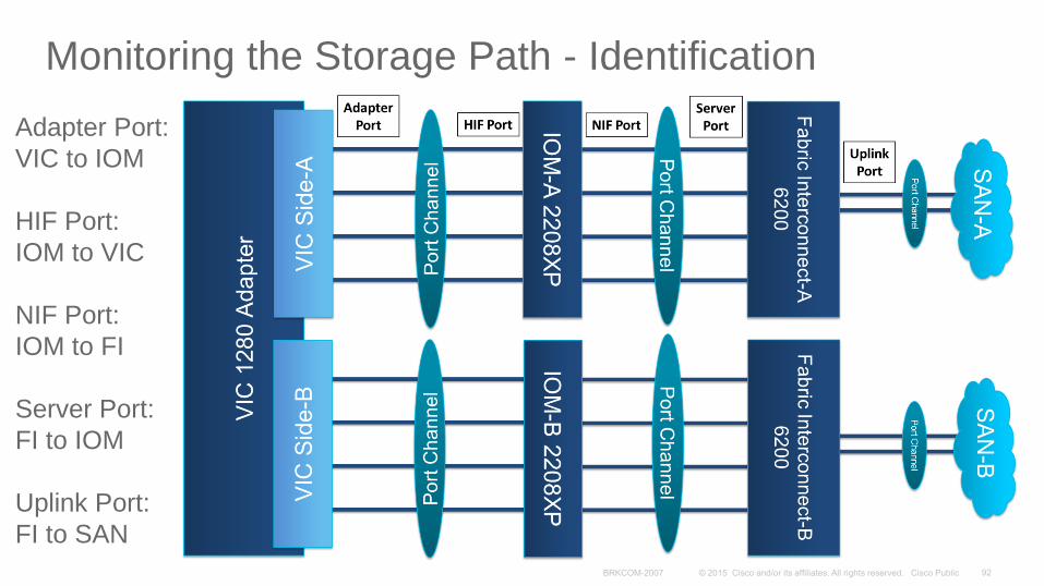
Monitoring the Storage Path - Identification
Adapter Port:
VIC to IOM
HIF Port:
IOM to VIC
NIF Port:
IOM to FI
Server Port:
FI to IOM
Uplink Port:
FI to SAN
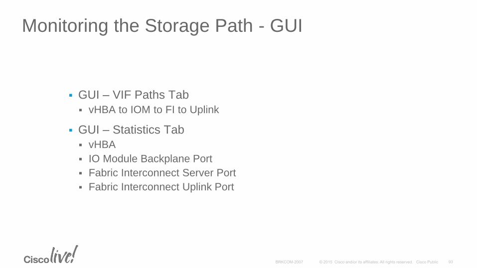
Monitoring the Storage Path - GUI
GUI – VIF Paths Tab
vHBA to IOM to FI to Uplink
GUI – Statistics Tab
vHBA
IO Module Backplane Port
Fabric Interconnect Server Port
Fabric Interconnect Uplink Port
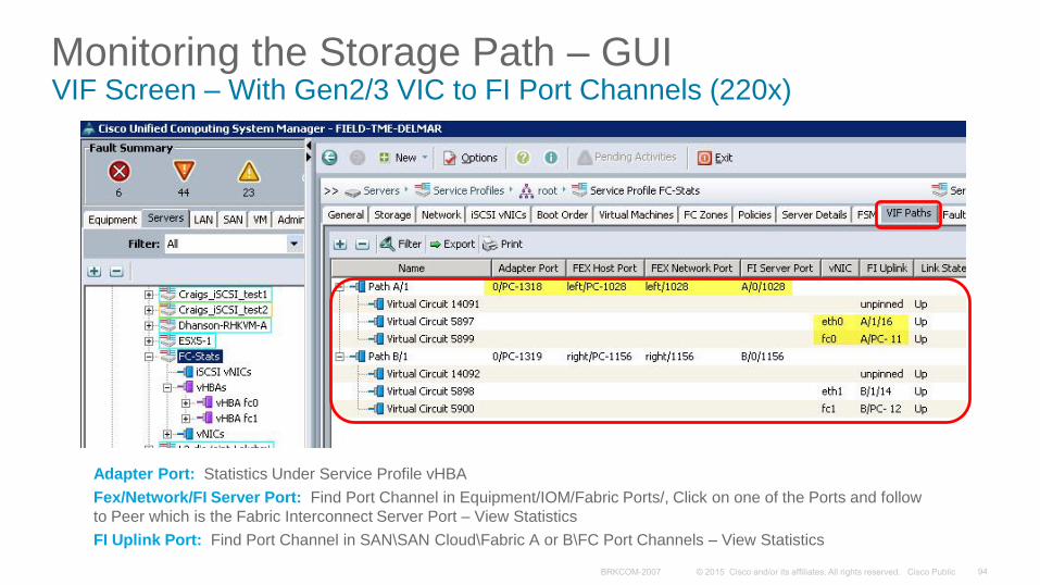
Monitoring the Storage Path – GUIVIF Screen – With Gen2/3 VIC to FI Port Channels (220x)
Adapter Port: Statistics Under Service Profile vHBA
Fex/Network/FI Server Port: Find Port Channel in Equipment/IOM/Fabric Ports/, Click on one of the Ports and follow
to Peer which is the Fabric Interconnect Server Port – View Statistics
FI Uplink Port: Find Port Channel in SAN\SAN Cloud\Fabric A or B\FC Port Channels – View Statistics
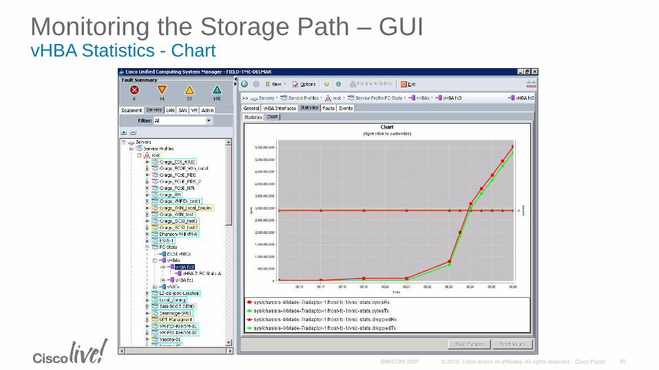
Monitoring the Storage Path – GUIvHBA Statistics - Chart
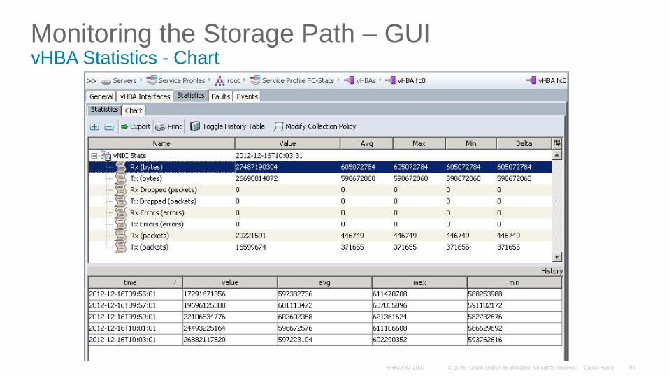
Monitoring the Storage Path – GUIvHBA Statistics - Chart
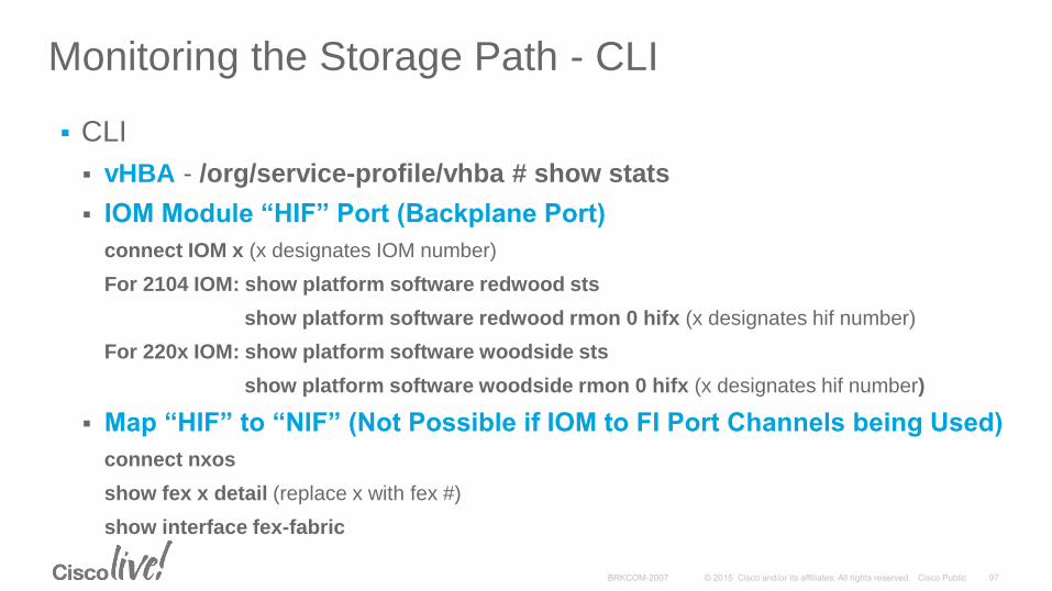
Monitoring the Storage Path - CLI
CLI
vHBA - /org/service-profile/vhba # show stats
IOM Module “HIF” Port (Backplane Port)
connect IOM x (x designates IOM number)
For 2104 IOM: show platform software redwood sts
show platform software redwood rmon 0 hifx (x designates hif number)
For 220x IOM: show platform software woodside sts
show platform software woodside rmon 0 hifx (x designates hif number)
Map “HIF” to “NIF” (Not Possible if IOM to FI Port Channels being Used)
connect nxos
show fex x detail (replace x with fex #)
show interface fex-fabric
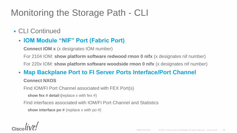
Monitoring the Storage Path - CLI
CLI Continued
IOM Module “NIF” Port (Fabric Port)
Connect IOM x (x designates IOM number)
For 2104 IOM: show platform software redwood rmon 0 nifx (x designates nif number)
For 220x IOM: show platform software woodside rmon 0 nifx (x designates nif number)
Map Backplane Port to FI Server Ports Interface/Port Channel
Connect NXOS
Find IOM/FI Port Channel associated with FEX Port(s)
show fex # detail (replace x with fex #)
Find interfaces associated with IOM/FI Port Channel and Statistics
show interface po # (replace x with po #)
Monitoring the Storage Path - CLI
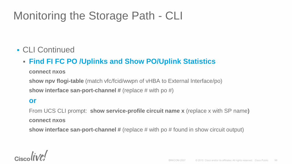
CLI Continued
Find FI FC PO /Uplinks and Show PO/Uplink Statistics
connect nxos
show npv flogi-table (match vfc/fcid/wwpn of vHBA to External Interface/po)
show interface san-port-channel # (replace # with po #)
or
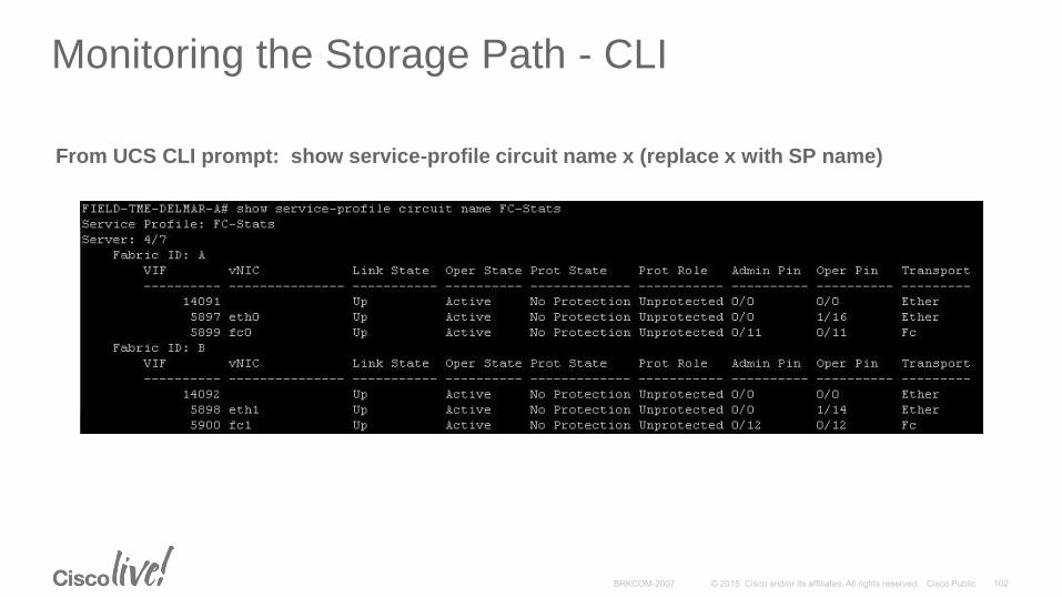
From UCS CLI prompt: show service-profile circuit name x (replace x with SP name)
connect nxos
show interface san-port-channel # (replace # with po # found in show circuit output)
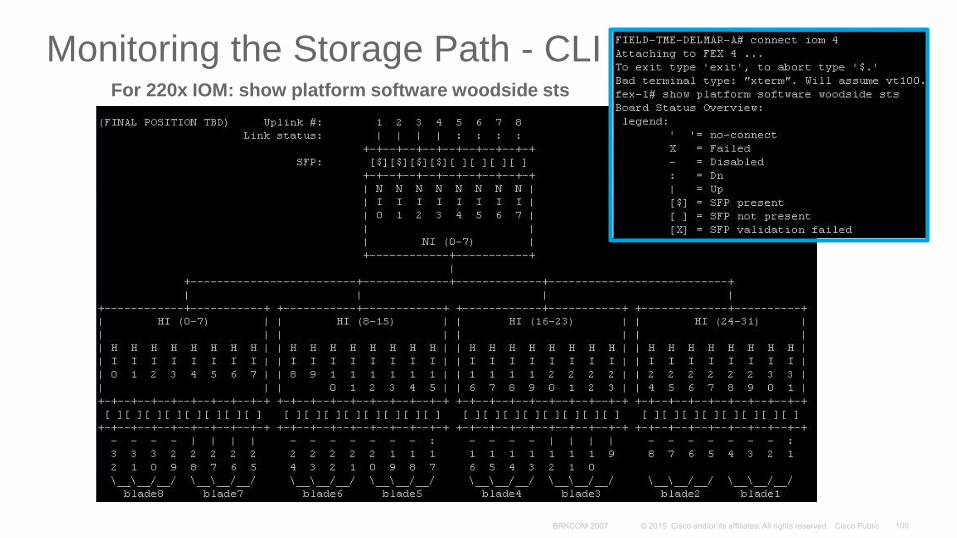
Monitoring the Storage Path - CLIFor 220x IOM: show platform software woodside sts
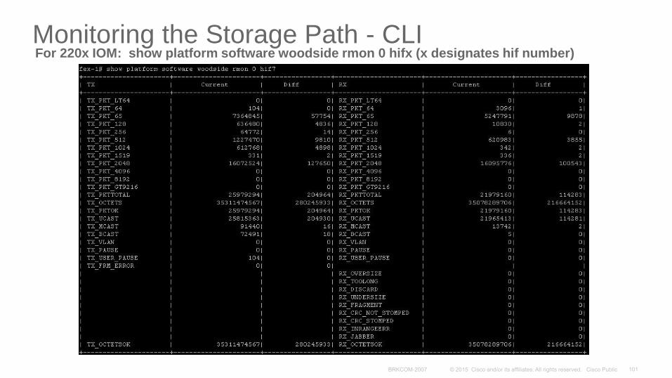
Monitoring the Storage Path - CLIFor 220x IOM: show platform software woodside rmon 0 hifx (x designates hif number)
Monitoring the Storage Path - CLI
From UCS CLI prompt: show service-profile circuit name x (replace x with SP name)
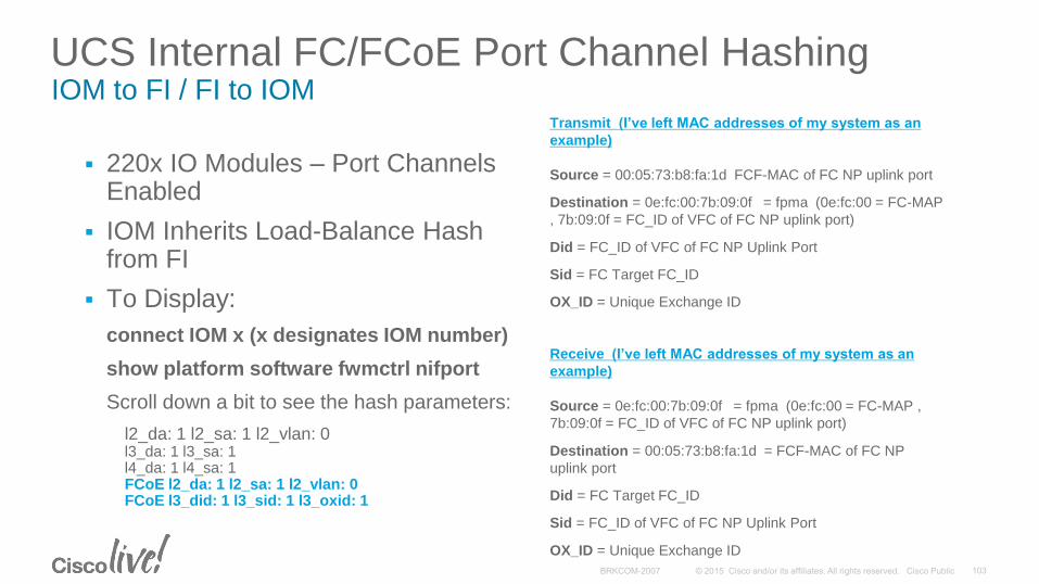
UCS Internal FC/FCoE Port Channel HashingIOM to FI / FI to IOM
220x IO Modules – Port Channels Enabled
IOM Inherits Load-Balance Hash from FI
To Display:
connect IOM x (x designates IOM number)
show platform software fwmctrl nifport
Scroll down a bit to see the hash parameters:
l2_da: 1 l2_sa: 1 l2_vlan: 0l3_da: 1 l3_sa: 1l4_da: 1 l4_sa: 1FCoE l2_da: 1 l2_sa: 1 l2_vlan: 0FCoE l3_did: 1 l3_sid: 1 l3_oxid: 1
Transmit (I’ve left MAC addresses of my system as an
example)
Source = 00:05:73:b8:fa:1d FCF-MAC of FC NP uplink port
Destination = 0e:fc:00:7b:09:0f = fpma (0e:fc:00 = FC-MAP
, 7b:09:0f = FC_ID of VFC of FC NP uplink port)
Did = FC_ID of VFC of FC NP Uplink Port
Sid = FC Target FC_ID
OX_ID = Unique Exchange ID
Receive (I’ve left MAC addresses of my system as an
example)
Source = 0e:fc:00:7b:09:0f = fpma (0e:fc:00 = FC-MAP ,
7b:09:0f = FC_ID of VFC of FC NP uplink port)
Destination = 00:05:73:b8:fa:1d = FCF-MAC of FC NP
uplink port
Did = FC Target FC_ID
Sid = FC_ID of VFC of FC NP Uplink Port
OX_ID = Unique Exchange ID
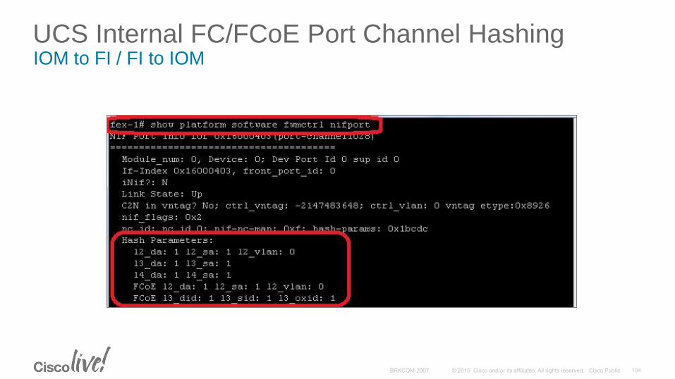
UCS Internal FC/FCoE Port Channel HashingIOM to FI / FI to IOM
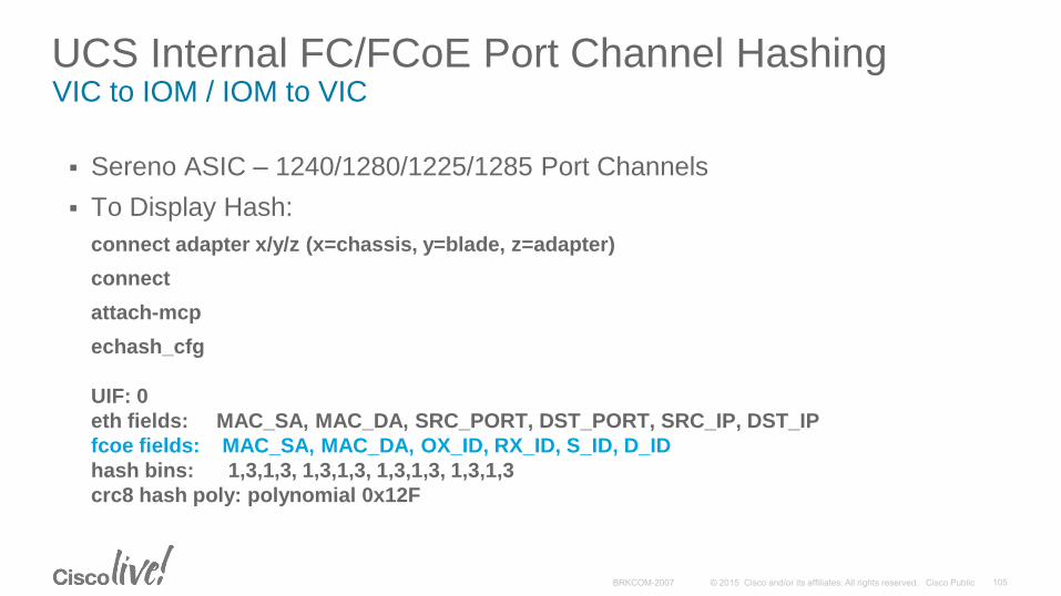
UCS Internal FC/FCoE Port Channel HashingVIC to IOM / IOM to VIC
Sereno ASIC – 1240/1280/1225/1285 Port Channels
To Display Hash:
connect adapter x/y/z (x=chassis, y=blade, z=adapter)
connect
attach-mcp
echash_cfg
UIF: 0
eth fields: MAC_SA, MAC_DA, SRC_PORT, DST_PORT, SRC_IP, DST_IP
fcoe fields: MAC_SA, MAC_DA, OX_ID, RX_ID, S_ID, D_ID
hash bins: 1,3,1,3, 1,3,1,3, 1,3,1,3, 1,3,1,3
crc8 hash poly: polynomial 0x12F
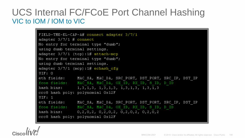
UCS Internal FC/FCoE Port Channel HashingVIC to IOM / IOM to VIC
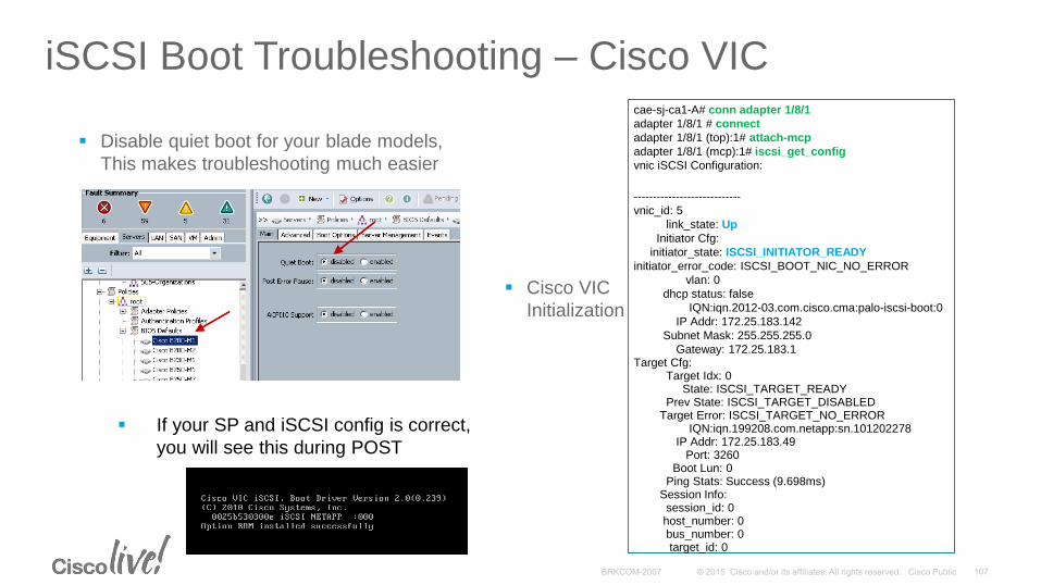
iSCSI Boot Troubleshooting – Cisco VIC
Disable quiet boot for your blade models,
This makes troubleshooting much easier
If your SP and iSCSI config is correct,
you will see this during POST
cae-sj-ca1-A# conn adapter 1/8/1
adapter 1/8/1 # connect
adapter 1/8/1 (top):1# attach-mcp
adapter 1/8/1 (mcp):1# iscsi_get_config
vnic iSCSI Configuration:
----------------------------
vnic_id: 5
link_state: Up
Initiator Cfg:
initiator_state: ISCSI_INITIATOR_READY
initiator_error_code: ISCSI_BOOT_NIC_NO_ERROR
vlan: 0
dhcp status: false
IQN:iqn.2012-03.com.cisco.cma:palo-iscsi-boot:0
IP Addr: 172.25.183.142
Subnet Mask: 255.255.255.0
Gateway: 172.25.183.1Target Cfg:
Target Idx: 0State: ISCSI_TARGET_READY
Prev State: ISCSI_TARGET_DISABLEDTarget Error: ISCSI_TARGET_NO_ERROR
IQN:iqn.199208.com.netapp:sn.101202278IP Addr: 172.25.183.49
Port: 3260Boot Lun: 0
Ping Stats: Success (9.698ms)Session Info: session_id: 0host_number: 0bus_number: 0target_id: 0
Cisco VIC
Initialization
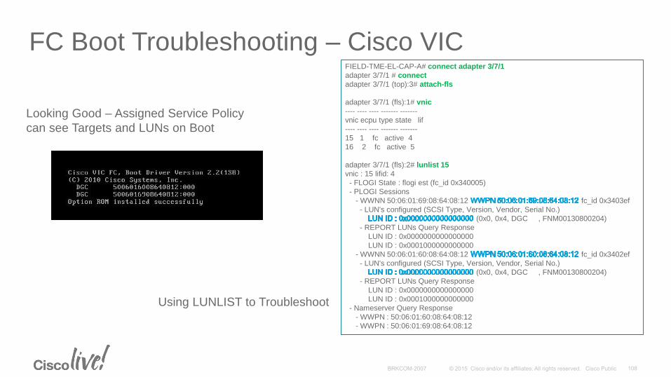
FC Boot Troubleshooting – Cisco VIC
Looking Good – Assigned Service Policy
can see Targets and LUNs on Boot
Using LUNLIST to Troubleshoot
FIELD-TME-EL-CAP-A# connect adapter 3/7/1
adapter 3/7/1 # connect
adapter 3/7/1 (top):3# attach-fls
adapter 3/7/1 (fls):1# vnic
---- ---- ---- ------- -------
vnic ecpu type state lif
---- ---- ---- ------- -------
15 1 fc active 4
16 2 fc active 5
adapter 3/7/1 (fls):2# lunlist 15
vnic : 15 lifid: 4
- FLOGI State : flogi est (fc_id 0x340005)
- PLOGI Sessions
- WWNN 50:06:01:69:08:64:08:12 fc_id 0x3403ef
- LUN's configured (SCSI Type, Version, Vendor, Serial No.)
(0x0, 0x4, DGC , FNM00130800204)
- REPORT LUNs Query Response
LUN ID : 0x0000000000000000
LUN ID : 0x0001000000000000
- WWNN 50:06:01:60:08:64:08:12 fc_id 0x3402ef
- LUN's configured (SCSI Type, Version, Vendor, Serial No.)
(0x0, 0x4, DGC , FNM00130800204)
- REPORT LUNs Query Response
LUN ID : 0x0000000000000000
LUN ID : 0x0001000000000000
- Nameserver Query Response
- WWPN : 50:06:01:60:08:64:08:12
- WWPN : 50:06:01:69:08:64:08:12
UCS FNIC Driver Enhancements
Enhanced FNIC Driver Parameters (Tunables) Queue Depth (Boot/Load/Run Time)
I/O Throttle Count (Boot )
Please see Cisco UCS fNIC Tunables Guide:http://www.cisco.com/c/dam/en/us/solutions/collateral/data-center-virtualization/unified-computing/guide-c07-730811.pdf
Enhanced FNIC Driver Statistics Cumulative and Point in Time
I/O and Control Path
Per fNIC (per vHBA)
debugfs (Linux), IOCTL / fnic-tracetool (VMWare)
Please see Cisco UCS fNIC Statistics Guide:http://www.cisco.com/c/dam/en/us/solutions/collateral/data-center-virtualization/unified-computing/guide_c07-730810.pdf
UCSM 2.1.2(a) and Above
fNIC Driver 1.5.0.45 and Above
Linux / VMWare (See HCL for Supported Distributions
Storage Vendor Support
Different Levels of Storage Vendor Qualifications
Cisco tests the majority of the leading array vendors in a collaborative fashion with both vendor and Cisco labs.
Self-cert program is in place for remainder of the market.
Cross Postings on HCLs – Aim is to match Cisco HCL + Storage HCL
Storage Arrays – Too many to list! Continuous qualifications and re-qualifications.
Switch Interoperability – Cisco, Brocade - Cisco Testing (All)
Tape Libraries – Oracle, Quantum, IBM with Various Backup Apps
Please Consult Appropriate HCL for Details http://www.cisco.com/en/US/products/ps10477/prod_technical_reference_list.html
Participate in the “My Favorite Speaker” Contest
• Promote your favorite speaker through Twitter and you could win $200 of Cisco Press products (@CiscoPress)
• Send a tweet and include
• Your favorite speaker’s Twitter handle <CraigAshapa@CraigAshapa>
• Two hashtags: #CLUS #MyFavoriteSpeaker
• You can submit an entry for more than one of your “favorite” speakers
• Don’t forget to follow @CiscoLive and @CiscoPress
• View the official rules at http://bit.ly/CLUSwin
Promote Your Favorite Speaker and You Could be a Winner
Complete Your Online Session Evaluation
Don’t forget: Cisco Live sessions will be available for viewing on-demand after the event at CiscoLive.com/Online
• Give us your feedback to be entered into a Daily Survey Drawing. A daily winner will receive a $750 Amazon gift card.
• Complete your session surveys though the Cisco Live mobile app or your computer on Cisco Live Connect.
Continue Your Education
• Demos in the Cisco Campus
• Walk-in Self-Paced Labs
• Table Topics
• Meet the Engineer 1:1 meetings
Thank you