ubi-2590 hc smbus (part no. ubbl13) - ultralife · pdf fileubi-2590 hc smbus (part no. ubbl13)...
TRANSCRIPT
UBI-2590 HC SMBus (Part No. UBBL13) Battery Specification
Newark, New York | 315-332-7100 | Fax: 315-331-7800 ©2012 Ultralife Corporation • www.ultralifecorp.com • All specific information is subject to change without notice
The information contained herein is for reference only and does not constitute a warrant of performance • 18 DEC 12 UBM-05220 Rev: D
UBI-2590 HC SMBus (Part No. UBBL13) Battery Specification
UBI-2590 HC SMBus (Part No. UBBL13) Battery Specification Newark, New York | 315-332-7100 | Fax: 315-331-7800
©2012 Ultralife Corporation • www.ultralifecorp.com • All specific information is subject to change without notice The information contained herein is for reference only and does not constitute a warrant of performance • 18 DEC 12 UBM-05220 Rev: D
Copyright Copyright © 2012, Ultralife Corporation. All Rights Reserved.
Trademark Information Ultralife, the Ultralife logo design, SmartCircuit Technology and the SmartCircuit logo design are trademarks or registered trademarks of Ultralife Corporation.
Disclaimer of Liability Information and descriptions contained in this manual are the property of Ultralife Corporation. Distribution and/or reproduction in part or in whole are expressly forbidden without written consent.
Ultralife Corp believes that information in this publication is accurate as of its publication date. Ultralife Corp. reserves the right to change the contents without prior notice and is not responsible for any inadvertent errors.
Ultralife Corporation 2000 Technology Parkway Newark, New York 14513 Phone: (315) 332-7100 Fax: (315) 331-7800 Email: [email protected] http://www.ultralifecorporation.com/
UBI-2590 HC SMBus (Part No. UBBL13) Battery Specification
Newark, New York | 315-332-7100 | Fax: 315-331-7800 ©2012 Ultralife Corporation • www.ultralifecorp.com • All specific information is subject to change without notice
The information contained herein is for reference only and does not constitute a warrant of performance • 18 DEC 12 UBM-05220 Rev: D
CONTENTS 1. Document Scope .......................................................................................................................................... 4 2. Important Nomenclature ............................................................................................................................... 4 3. Battery Description ....................................................................................................................................... 4 4. Battery Compatibility .................................................................................................................................... 4 5. Battery Capacity (C) ..................................................................................................................................... 4 6. Voltage ......................................................................................................................................................... 4 7. Discharge Current ........................................................................................................................................ 4 8. Charge Instructions ...................................................................................................................................... 5 9. Temperature Storage ................................................................................................................................... 6 10. Operational Temperature ............................................................................................................................. 6 11. Capacity Testing ........................................................................................................................................... 7 12. Cycle Life Testing ....................................................................................................................................... 10 13. Shelf Life .................................................................................................................................................... 10 14. Dimensions ................................................................................................................................................. 10 15. Weight ........................................................................................................................................................ 11 16. Case Material ............................................................................................................................................. 11 17. Case Color ................................................................................................................................................. 11 18. Label requirements ..................................................................................................................................... 11 19. Connector ................................................................................................................................................... 11 20. Battery Protection Circuit ........................................................................................................................... 11 21. State of Charge Indication (SOCI) ............................................................................................................. 11 22. Chargers and Charge Control Chipsets ..................................................................................................... 12 23. Quality and Workmanship .......................................................................................................................... 12 24. Shipping and Transportation Requirements .............................................................................................. 12 25. Safety Requirements .................................................................................................................................. 12

UBI-2590 HC SMBus (Part No. UBBL13) Battery Specification
Newark, New York | 315-332-7100 | Fax: 315-331-7800 ©2012 Ultralife Corporation • www.ultralifecorp.com • All specific information is subject to change without notice
The information contained herein is for reference only and does not constitute a warrant of performance • 18 DEC 12 UBM-05220 Rev: D
1. Document Scope
1.1. This document pertains to the performance, operation of, and the physical characteristics of the UBI-2590 High Capacity (HC) SMBus battery pack.
1.2. All information contained in this specification is targeted for single battery applications, where each section is used either in parallel or series. For applications using multiple batteries in parallel and/or series combinations, please contact Ultralife customer assistance for technical review and approval. Use of the battery in any multiple parallel and/or series combination without Ultralife technical approval will void any and all warranties of said product. Ultralife does not suggest that this product be used in multiple parallel or series configurations without additional safety and circuit protection devices, and failure to add said devices will result in assumed liability.
2. Important Nomenclature
2.1. Ambient Conditions: 25°C ±3°C 2.2. C Rate: The rate at which 100% capacity is obtained under ambient conditions in 1 hour of
constant current discharge
3. Battery Description 3.1. The UBI-2590, HC SMBus battery pack was originally designed as a rechargeable power
source for several military communication devices. The pack consists of two 14.4V batteries. The device in which the battery is used determines whether the battery is used in series (30V) mode or parallel (15V).
3.2. Typical Uses: AN/PRC-104, AN/PRC-119 (SINCGARS), KY-57 Radios. 3.3. The UBI-2590 SMBus battery employs ULBI’s Smart Circuit™ technology by providing SMBus
v1.1 smart battery tools via the SBD v1.0 dataset. 4. Battery Compatibility
4.1. Rechargeable Batteries: BB-2590, BB-390A/U, BB-590/U, BB-690/U, BT-2590, MAI-2590, MRC-2590, UBI-2590 (UBBL02), UBI-2590 (UBBL10).
4.2. Primary Batteries: BA-5390A/U, BA-5590/U, BA-5390/U, BA-3590/U 5. Battery Capacity (C)
5.1. 8.7 Ah in 30 volt mode (Pack A and Pack B Connected in Series) 5.2. 17.4 Ah in 15 volt mode (Pack A and Pack B Connected in Parallel)
6. Voltage
6.1. Max Voltage: 16.8 per section, 33.6 when connected in series 6.2. Nominal Voltage: 14.4 per section 6.3. Min Voltage: 12.0 per section
7. Discharge Current
7.1. Recommended Continuous Discharge Current: 9A in 15V mode or 4.5A in 30V mode. 7.2. Maximum Continuous Discharge Current: 18A in 15V mode or 9A in 30V mode. 7.3. Pulse Discharge
7.3.1. Max Pulse Currents: 36A for 5 seconds in 15V mode, 18A for 5 seconds in 30V mode 7.3.2. Pulse current and duty cycle will cause performance to vary greatly, especially at
temperature extremes. 7.4. NOTE: The continuous use of the battery at or near max discharge capability, especially at
elevated temperatures, will cause reset-able internal thermal protection devices to activate. 7.5. Battery ratings based upon C/5 (1.74A) discharge current under ambient conditions.

UBI-2590 HC SMBus (Part No. UBBL13) Battery Specification
Newark, New York | 315-332-7100 | Fax: 315-331-7800 ©2012 Ultralife Corporation • www.ultralifecorp.com • All specific information is subject to change without notice
The information contained herein is for reference only and does not constitute a warrant of performance • 18 DEC 12 UBM-05220 Rev: D
8. Charge Instructions 8.1. Charge each section at charge rate of 1.6A (maximum 3.0A) to maximum voltage of 16.8 volts
until current declines to 300mA in a temperature range of 0̊ C to 45˚C. See Figure 1 and 2.
Charging Individual Section of UBBL13 @ 23°C 16.8V Constant Voltage Charge with 1.6A Curent Limit
0
3
6
9
12
15
18
0 1 2 3 4 5 6Time (Hours)
Volta
ge (V
)
0
2
4
6
8
10
Capacity (A
h)
VoltageCurrentCapacity
Figure 1
Charging Individual Section of UBBL13 @ 23°C 16.8V Constant Voltage Charge with 3.0A Curent Limit
0
3
6
9
12
15
18
0 1 2 3Time (Hours)
Volta
ge (V
)
0
2
4
6
8
10
Capacity (A
h)
VoltageCurrentCapacity
Figure 2

UBI-2590 HC SMBus (Part No. UBBL13) Battery Specification
Newark, New York | 315-332-7100 | Fax: 315-331-7800 ©2012 Ultralife Corporation • www.ultralifecorp.com • All specific information is subject to change without notice
The information contained herein is for reference only and does not constitute a warrant of performance • 18 DEC 12 UBM-05220 Rev: D
8.2. Each section should be charged fully before use of the battery, especially when used in series mode, to keep each section of the pack in balance and prevent over discharge of one section.
8.3. NOTE: Charge times will vary based on charge current used, lower currents result in longer times
8.4. Battery sections are recommended to be charged only individually or in parallel, however if charged in parallel then charge time will increase. See Figure 3.
Parallel Mode Charge @ 23°C16.8V Constant Voltage Charge with 3.0A Current Limit
0
3
6
9
12
15
18
0 1 2 3 4 5 6Time (Hours)
Vol
tage
(V)
0
2
4
6
8
10
12
14
16
18
20
Capacity (A
h)
VoltageCurrentCapacity
Figure 3 9. Temperature Storage
9.1. Storage between -32°C and 60°C 9.2. Store battery between 0°C and 45°C for optimum performance. 9.3. Storage between 45°C and 60°C is possible, with product performance losses. 9.4. A temporary thermal disabling device will operate if internal pack temperature reaches 70±5°C.
It resets at 55±5°C.) 9.5. Storage above 91°C or an extended storage at 68°C will cause a permanent disabling device to
activate. 9.6. Do not store below 25% state of charge.
10. Operational Temperature
10.1. Operational between -32°C and 60°C 10.2. Operate battery between 10°C and 45°C for specified performance characteristics. 10.3. Operation outside of the specified window will result in lower product performance dependent
on application usage. 10.4. A temporary thermal disabling device will operate if internal pack temperature reaches 70±5°C.
It resets at 55±5°C.) 10.5. Operation above 91°C or an extended storage at 68°C will cause a permanent disabling device
to activate.

UBI-2590 HC SMBus (Part No. UBBL13) Battery Specification
Newark, New York | 315-332-7100 | Fax: 315-331-7800 ©2012 Ultralife Corporation • www.ultralifecorp.com • All specific information is subject to change without notice
The information contained herein is for reference only and does not constitute a warrant of performance • 18 DEC 12 UBM-05220 Rev: D
11. Capacity Testing 11.1. Rated capacity is specified as the C/5 discharge rate under ambient discharge conditions,
when previously completing charge at ambient conditions within 1 hour of discharge per the specified charge regime.
11.2. Parallel Mode Ambient Constant Current Discharges Voltage –v- Time. See Figure 4.
Parallel Mode (16.6V) at 23°C Constant Current Discharge (Rated Capacity = 17.4Ah)
Voltage vs Time
12
13
14
15
16
17
0 5 10 15 20 25 30 35 40Time (Hours)
Volta
ge (V
)
400mA1A2A3A4A
Figure 4

UBI-2590 HC SMBus (Part No. UBBL13) Battery Specification
Newark, New York | 315-332-7100 | Fax: 315-331-7800 ©2012 Ultralife Corporation • www.ultralifecorp.com • All specific information is subject to change without notice
The information contained herein is for reference only and does not constitute a warrant of performance • 18 DEC 12 UBM-05220 Rev: D
11.3. Parallel Mode Ambient Constant Current Discharges Voltage –v- Rated Capacity. See Figure 5.
Parallel Mode (16.6V) at 23°C Constant Current Discharge (Rated Capacity = 17.4Ah)
Voltage vs %Rated Capacity
12
13
14
15
16
17
0 10 20 30 40 50 60 70 80 90 100% Rated Capacity (Ahr)
Volta
ge (V
)
400mA1A2A3A4A
Figure 5
UBI-2590 HC SMBus (Part No. UBBL13) Battery Specification
Newark, New York | 315-332-7100 | Fax: 315-331-7800 ©2012 Ultralife Corporation • www.ultralifecorp.com • All specific information is subject to change without notice
The information contained herein is for reference only and does not constitute a warrant of performance • 18 DEC 12 UBM-05220 Rev: D
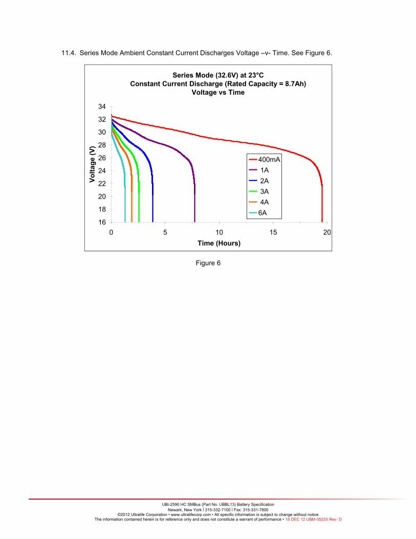
11.4. Series Mode Ambient Constant Current Discharges Voltage –v- Time. See Figure 6.
Series Mode (32.6V) at 23°C Constant Current Discharge (Rated Capacity = 8.7Ah)
Voltage vs Time
16
18
20
22
24
26
28
30
32
34
0 5 10 15 20Time (Hours)
Volta
ge (V
)
400mA 1A 2A 3A 4A6A
Figure 6

UBI-2590 HC SMBus (Part No. UBBL13) Battery Specification
Newark, New York | 315-332-7100 | Fax: 315-331-7800 ©2012 Ultralife Corporation • www.ultralifecorp.com • All specific information is subject to change without notice
The information contained herein is for reference only and does not constitute a warrant of performance • 18 DEC 12 UBM-05220 Rev: D
11.5. Series Mode Ambient Constant Current Discharges Voltage –v- Rated Capacity. See Figure 7.
Series Mode (32.6V) at 23°C Constant Current Discharge (Rated Capacity = 8.7Ah)
Voltage vs %Rated Capacity
16
18
20
22
24
26
28
30
32
34
0 10 20 30 40 50 60 70 80 90 100%Rated Capacity (Ahr)
Volta
ge (V
)
400mA 1A 2A 3A 4A6A
Figure 7
12. Cycle Life Testing 12.1. The pack will obtain 300 cycles at greater than 80% rated capacity at recommended charge
and C/5 discharge rates under ambient conditions. 13. Shelf Life
13.1. Self-discharge due to cells is typically less than 2% per month. 13.2. The battery pack should retain greater than 95% of the initial capacity when stored for 1 year
under ambient conditions when tested per the capacity test in section 11. 13.3. The battery pack should retain greater than 90% of the initial capacity when stored for 1 year at
temperatures above ambient and below 45°C when tested per the capacity test in section 11 13.4. The battery should retain greater than 85% of the initial of the initial capacity when stored for 6
months at temperatures above 45°C and below 60°C when tested per the capacity test in section 11.
13.5. The PCB with State of Charge Indication LCD, when in sleep mode (no current flow for more than 2 seconds), will consume current at an average of 0.35mA or a capacity of 8.4mAh per day. This is in addition to the cell self discharge. This occurs for each pack section independently.
13.6. The PCB with State of Charge Indication LCD, when in awake mode (current flow), will consume current at an average of 0.8 mA or a capacity of 19.2 mAh per day. This is in addition to the cell self discharge. This occurs for each pack section independently.
14. Dimensions
14.1. Maximum dimensions: 63.0mm x 112.5mm x 127.0mm (2.48” x 4.43” x 5.0”)
UBI-2590 HC SMBus (Part No. UBBL13) Battery Specification
Newark, New York | 315-332-7100 | Fax: 315-331-7800 ©2012 Ultralife Corporation • www.ultralifecorp.com • All specific information is subject to change without notice
The information contained herein is for reference only and does not constitute a warrant of performance • 18 DEC 12 UBM-05220 Rev: D
15. Weight 15.1. 1340 g maximum
16. Case Material
16.1. GE Noryl 190X 17. Case Color
17.1. Lusterless Black 18. Label requirements
18.1. The label will include manufacturer, location, and country of origin. 18.2. Safety Information and Warnings:
18.2.1. CHARGE INSTRUCTIONS: Charge each section at maximum 16.8V constant voltage with current of 1.6A (max 3.0A). Recommended battery temperature during charging should be between 32°F (0°C) and 113°F (45°C). Lower temperature charging is permitted but run times will be lower.
18.2.2. WARNING/ STORAGE: Store at 50% capacity. Do not store above 140°F (60°C), Crush, Mutilate, Reverse Polarity, Disassemble, or Dispose of in Fire.
18.3. The label shall be legible and free from visible defects such as wrinkles and cracks. 18.4. The battery pack will be serialized to maintain trace ability. 18.5. The connector contacts will be clearly labeled for polarity.
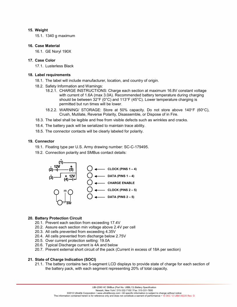
19. Connector 19.1. Floating type per U.S. Army drawing number: SC-C-179495. 19.2. Connection polarity and SMBus contact details:
20. Battery Protection Circuit
20.1. Prevent each section from exceeding 17.4V 20.2. Assure each section min voltage above 2.4V per cell 20.3. All cells prevented from exceeding 4.35V 20.4. All cells prevented from discharge below 2.75V 20.5. Over current protection setting: 19.0A 20.6. Typical Discharge current is 4A and below 20.7. Prevent external short circuit of the pack (Current in excess of 18A per section)
21. State of Charge Indication (SOCI) 21.1. The battery contains two 5-segment LCD displays to provide state of charge for each section of
the battery pack, with each segment representing 20% of total capacity.
(6)
SW
CLOCK (PINS 1 – 4)
DATA (PINS 1 – 4)
CHARGE ENABLE
CLOCK (PINS 2 – 5)
DATA (PINS 2 – 5)
UBI-2590 HC SMBus (Part No. UBBL13) Battery Specification
Newark, New York | 315-332-7100 | Fax: 315-331-7800 ©2012 Ultralife Corporation • www.ultralifecorp.com • All specific information is subject to change without notice
The information contained herein is for reference only and does not constitute a warrant of performance • 18 DEC 12 UBM-05220 Rev: D
21.2. When the capacity is below 5%, the last remaining bar on the display will begin to flash as a warning of low capacity.
21.3. The state of charge chipset requires a complete discharge followed by a complete charge to remain accurate.
22. Chargers and Charge Control Chipsets
22.1. Only use approved chargers or chipsets that operate within specified charge profile requirements. Available optional chargers are: CH0002, CH0003, CH0004, MRC-85A, MRC-86A, MRC-88, MRC-135A, MRC-143A and UKT0011.
22.2. Lower charge currents are acceptable, but result in increased charge time requirements.
23. Quality and Workmanship 23.1. The battery case and connector will be free of visible scratches, cracks, and or damage.
24. Shipping and Transportation Requirements 24.1. The battery pack will be shipped at 50% capacity, to allow storage in sleep mode (no current
flow for more than 2 seconds) for up to 1 year without recharging. 24.2. UN T1 – T8 testing completed and passed. 24.3. Class 9 International and within US unless shipped by motorcar or rail within the US.
25. Safety Requirements 25.1. Only specified connectors and cables should be used to connect with battery pack, such as
Ultralife part numbers: CA0002, CA0003, CA0006, CA0007, CA0008 and UCA0039. 25.2. Do not store above 60°C (140°F), Crush, Mutilate, Reverse Polarity, Disassemble, or Dispose
of in Fire.