uavsar · polar year (ipy) to a permanently available ka-band uavsar configuration. •improve ipy...
TRANSCRIPT
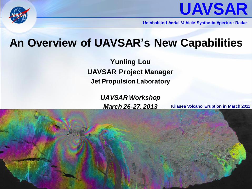
An Overview of UAVSAR’s New Capabilities
Yunling Lou
UAVSAR Project Manager
Jet Propulsion Laboratory
UAVSAR Workshop
March 26-27, 2013
UAVSAR Uninhabited Aerial Vehicle Synthetic Aperture Radar
Kilauea Volcano Eruption in March 2011

Agenda
UAVSAR Overview
New Instrument Capabilities
New Platform Capabilities
UAVSAR Technology Roadmap
2
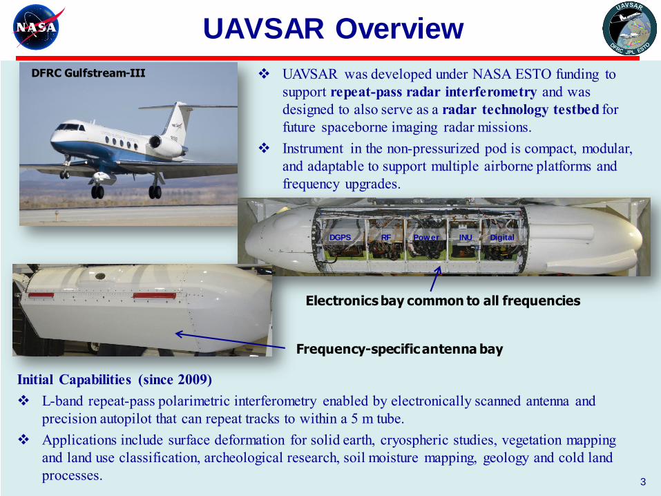
UAVSAR Overview
3
Initial Capabilities (since 2009)
L-band repeat-pass polarimetric interferometry enabled by electronically scanned antenna and
precision autopilot that can repeat tracks to within a 5 m tube.
Applications include surface deformation for solid earth, cryospheric studies, vegetation mapping
and land use classification, archeological research, soil moisture mapping, geology and cold land
processes.
DFRC Gulfstream-III
Frequency-specific antenna bay
DGPS RF Power INU Digital
Electronics bay common to all frequencies
UAVSAR was developed under NASA ESTO funding to
support repeat-pass radar interferometry and was
designed to also serve as a radar technology testbed for
future spaceborne imaging radar missions.
Instrument in the non-pressurized pod is compact, modular,
and adaptable to support multiple airborne platforms and
frequency upgrades.
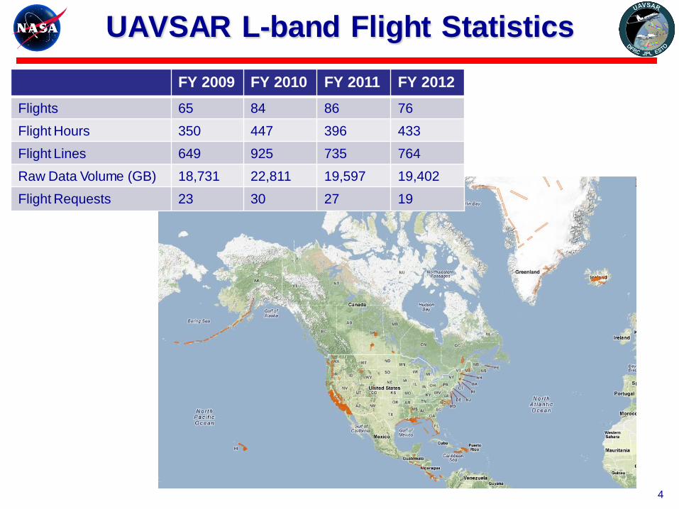
UAVSAR L-band Flight Statistics
FY 2009 FY 2010 FY 2011 FY 2012
Flights 65 84 86 76
Flight Hours 350 447 396 433
Flight Lines 649 925 735 764
Raw Data Volume (GB) 18,731 22,811 19,597 19,402
Flight Requests 23 30 27 19
4

Data Acquisition by Discipline
5
Engineering
Hydrology
(SMAP)
Oceanography
Solid Earth (earthquakes)
Solid Earth
(other deformations)
Solid Earth
(volcanoes)
Terrestrial
Ecology
Most campaigns are multi-year efforts:
– San Andreas fault monitoring
– Sacramento Delta levee study
– Hawaii & Aleutian volcano monitoring
– Gulf of Mexico oil spill impact study
– Iceland temperate glacier study
Other major campaigns included:
– SMAP 2010 and 2012 algorithm
validation experiments in Canada
– Terrestrial ecology studies in temperate
forests (New England) and tropical
forests (Costa Rica)
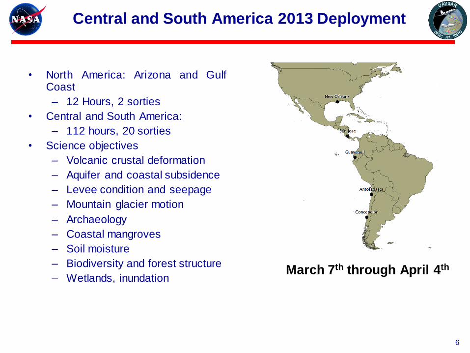
Central and South America 2013 Deployment
• North America: Arizona and Gulf Coast
– 12 Hours, 2 sorties
• Central and South America:
– 112 hours, 20 sorties
• Science objectives
– Volcanic crustal deformation
– Aquifer and coastal subsidence
– Levee condition and seepage
– Mountain glacier motion
– Archaeology
– Coastal mangroves
– Soil moisture
– Biodiversity and forest structure
– Wetlands, inundation
March 7th through April 4th
6
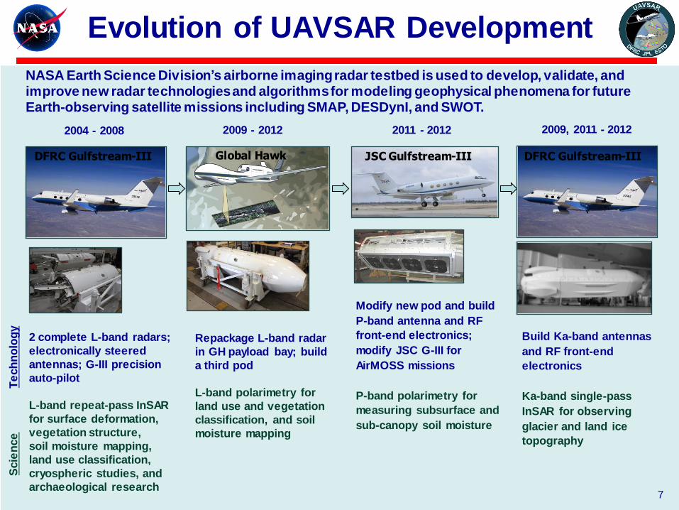
Evolution of UAVSAR Development
DFRC Gulfstream-III
Build Ka-band antennas
and RF front-end
electronics
Ka-band single-pass
InSAR for observing
glacier and land ice
topography
Modify new pod and build
P-band antenna and RF
front-end electronics;
modify JSC G-III for
AirMOSS missions
P-band polarimetry for
measuring subsurface and
sub-canopy soil moisture
Global Hawk
Repackage L-band radar
in GH payload bay; build
a third pod
L-band polarimetry for
land use and vegetation
classification, and soil
moisture mapping
NASA Earth Science Division’s airborne imaging radar testbed is used to develop, validate, and improve new radar technologies and algorithms for modeling geophysical phenomena for future Earth-observing satellite missions including SMAP, DESDynI, and SWOT.
2 complete L-band radars;
electronically steered
antennas; G-III precision
auto-pilot
L-band repeat-pass InSAR
for surface deformation,
vegetation structure,
soil moisture mapping,
land use classification,
cryospheric studies, and
archaeological research
2004 - 2008 2009 - 2012 2011 - 2012 2009, 2011 - 2012
JSC Gulfstream-III
Scie
nce
T
ech
no
log
y
DFRC Gulfstream-III
7
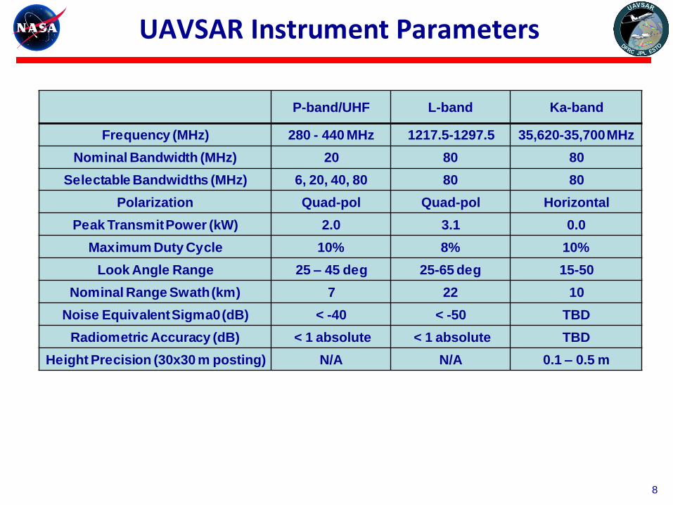
UAVSAR Instrument Parameters
8
P-band/UHF L-band Ka-band
Frequency (MHz) 280 - 440 MHz 1217.5-1297.5 35,620-35,700 MHz
Nominal Bandwidth (MHz) 20 80 80
Selectable Bandwidths (MHz) 6, 20, 40, 80 80 80
Polarization Quad-pol Quad-pol Horizontal
Peak Transmit Power (kW) 2.0 3.1 0.0
Maximum Duty Cycle 10% 8% 10%
Look Angle Range 25 – 45 deg 25-65 deg 15-50
Nominal Range Swath (km) 7 22 10
Noise Equivalent Sigma0 (dB) < -40 < -50 TBD
Radiometric Accuracy (dB) < 1 absolute < 1 absolute TBD
Height Precision (30x30 m posting) N/A N/A 0.1 – 0.5 m
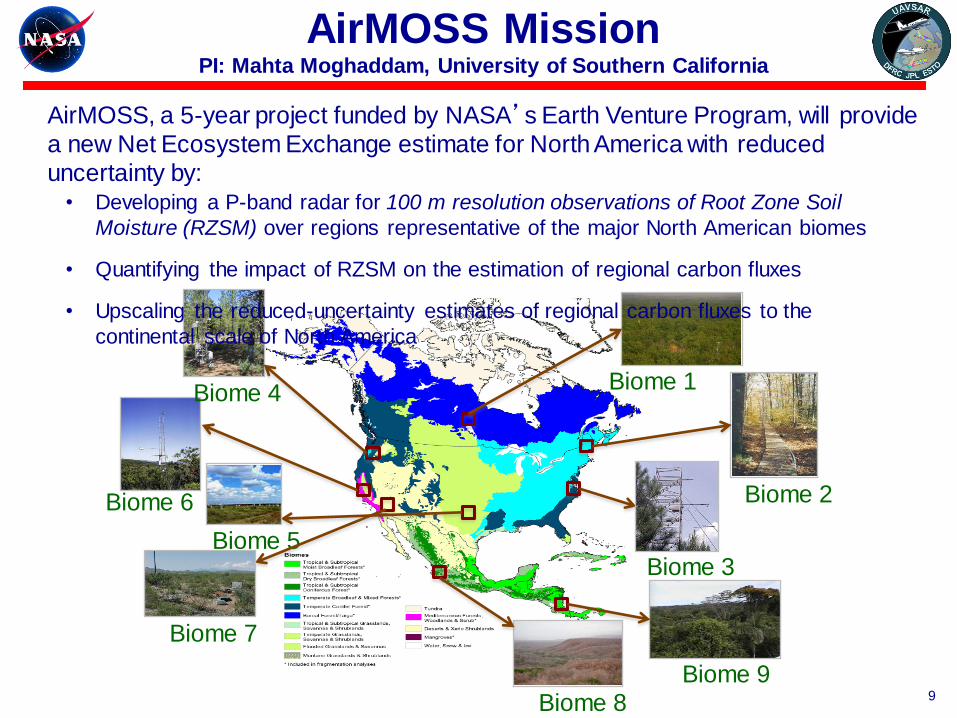
Biome 6
Biome 1
Biome 3
Biome 2
Biome 9
Biome 4
Biome 7
Biome 8
Biome 5
AirMOSS Mission PI: Mahta Moghaddam, University of Southern California
9
AirMOSS, a 5-year project funded by NASA’s Earth Venture Program, will provide
a new Net Ecosystem Exchange estimate for North America with reduced
uncertainty by: • Developing a P-band radar for 100 m resolution observations of Root Zone Soil
Moisture (RZSM) over regions representative of the major North American biomes
• Quantifying the impact of RZSM on the estimation of regional carbon fluxes
• Upscaling the reduced-uncertainty estimates of regional carbon fluxes to the
continental scale of North America
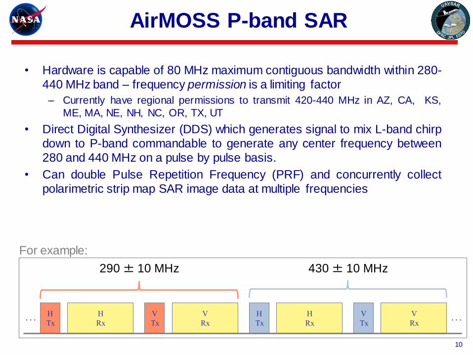
AirMOSS P-band SAR
10
• Hardware is capable of 80 MHz maximum contiguous bandwidth within 280-
440 MHz band – frequency permission is a limiting factor
– Currently have regional permissions to transmit 420-440 MHz in AZ, CA, KS,
ME, MA, NE, NH, NC, OR, TX, UT
• Direct Digital Synthesizer (DDS) which generates signal to mix L-band chirp
down to P-band commandable to generate any center frequency between
280 and 440 MHz on a pulse by pulse basis.
• Can double Pulse Repetition Frequency (PRF) and concurrently collect
polarimetric strip map SAR image data at multiple frequencies
H
Tx
H
Rx
V
Tx
V
Rx
H
Tx
H
Rx
V
Tx
V
Rx
290 ± 10 MHz 430 ± 10 MHz
… …
For example:
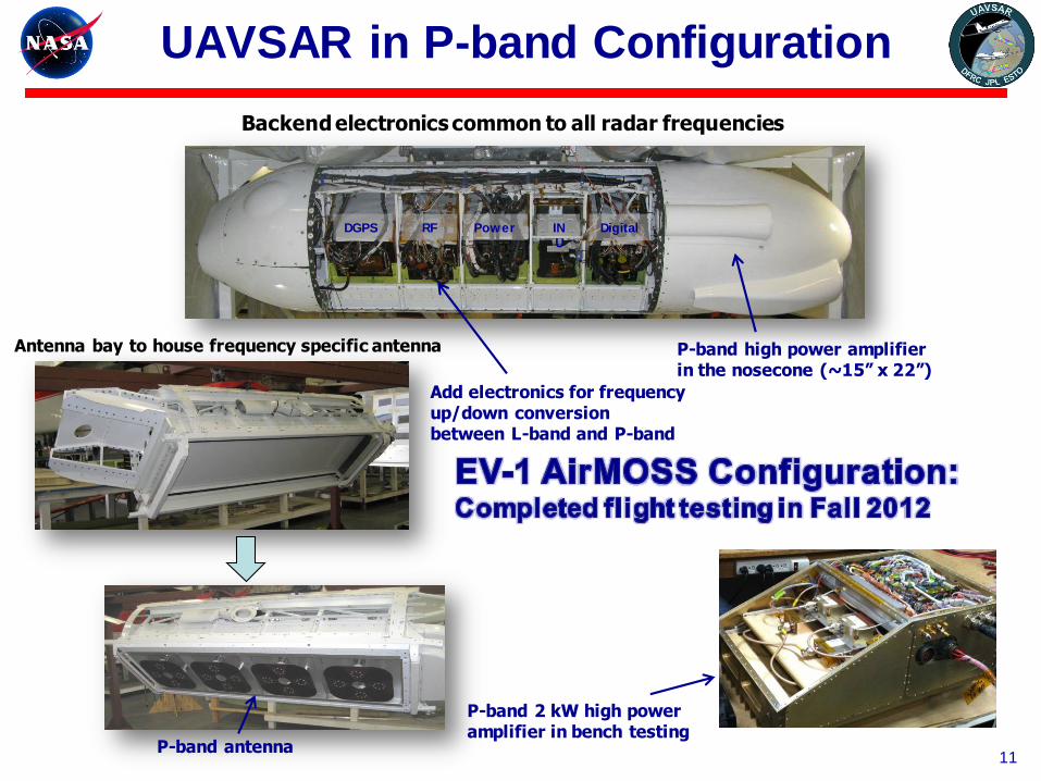
UAVSAR in P-band Configuration
P-band antenna
Backend electronics common to all radar frequencies
DGPS RF Power IN
U
Digital
Antenna bay to house frequency specific antenna P-band high power amplifier in the nosecone (~15” x 22”)
Add electronics for frequency up/down conversion between L-band and P-band
P-band 2 kW high power amplifier in bench testing
11

Deployment of 4.8 m Corner Reflectors
12
AirMOSS team posing with the corner reflector after completion of the fifth reflector
under 100ºF weather.

First P-band Imagery
13
4.8 m corner reflector array
2.4 m corner
reflector array

The Airborne Glacier and Land Ice Surface Topography
Interferometer (GLISTIN-A)
PI: Delwyn Moller, Remote Sensing Solutions, Inc.
• Provide an ice surface topography, swath mapping sensor capable of operationally
supporting NASA cryospheric science campaigns including potential IceBridge participation
and ICESat-II augmentation - especially in coastal regions.
• Transition the Ka-band interferometer capability developed under the NASA International
Polar Year (IPY) to a permanently available Ka-band UAVSAR configuration.
• Improve IPY configuration to provide enhanced performance and swath-mapping capability.
• Enable compact “plug and play” reconfiguration between L-band UAVSAR and Ka-band.
Ka-band antennas on the NASA GIII for single-pass interferometry
Example height map over Greenland’s coast collected 5/1/2009. Color wrap is 800 m and swath is 7.5km. GLISTIN-A will improve swath coverage to >10km.
14
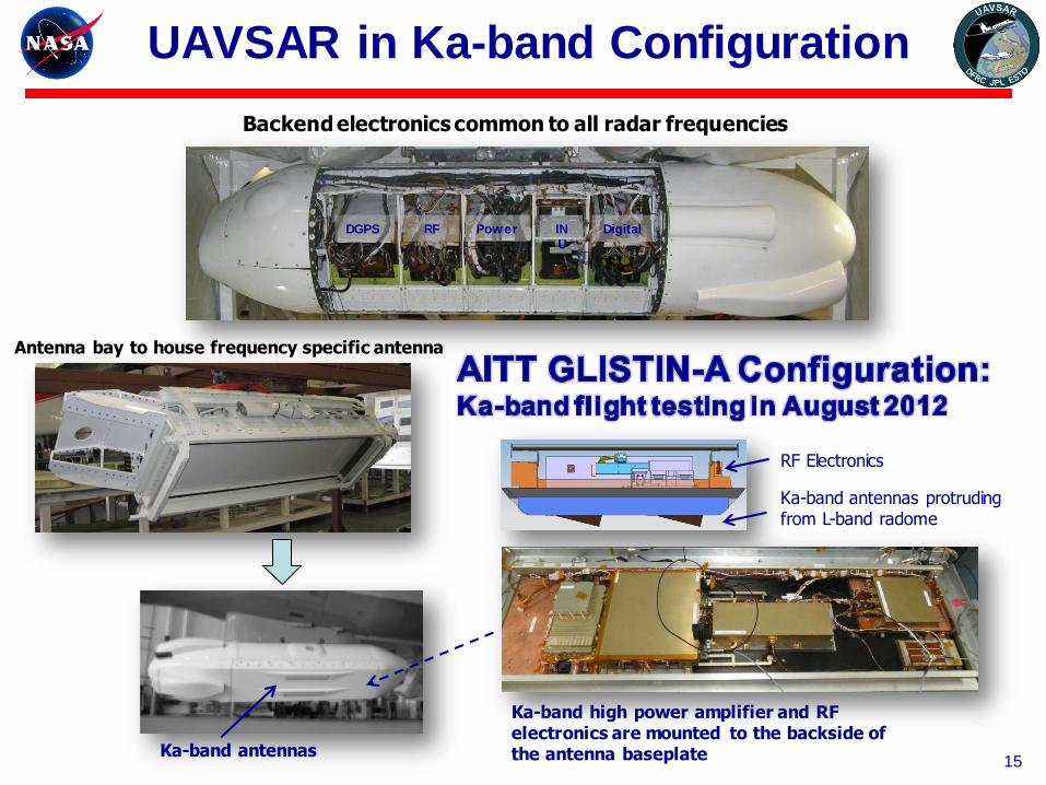
UAVSAR in Ka-band Configuration
Ka-band antennas
Backend electronics common to all radar frequencies
DGPS RF Power IN
U
Digital
Antenna bay to house frequency specific antenna
Ka-band high power amplifier and RF electronics are mounted to the backside of the antenna baseplate
Ka-band antennas protruding from L-band radome
RF Electronics
15
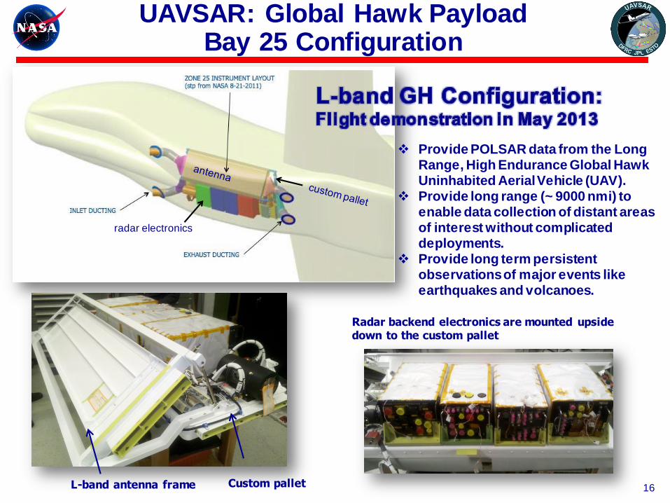
UAVSAR: Global Hawk Payload Bay 25 Configuration
L-band antenna frame
Radar backend electronics are mounted upside down to the custom pallet
Custom pallet
radar electronics
Provide POLSAR data from the Long Range, High Endurance Global Hawk Uninhabited Aerial Vehicle (UAV).
Provide long range (~ 9000 nmi) to enable data collection of distant areas of interest without complicated deployments.
Provide long term persistent observations of major events like earthquakes and volcanoes.
16

Summary of Instrument Upgrade Status
17
UAVSAR Program now has 3 pod-based radars, capable of operating
in repeat-pass P-band polarimetry, L-band polarimetry, and Ka-band
single pol. topographic interferometry.
With 2 G-IIIs capable of precision autopilot, we could potentially have
near simultaneous multi-frequency radar observations or formation
flying with 2 L-band radars.
P-band POLSAR flight testing onboard the JSC G-III was completed in
September 2012.
New capability will enable root zone soil moisture measurements
and other subsurface and sub-canopy measurements.
Ka-band HH pol single-pass interferometry began flight testing in
August 2012 onboard the DFRC G-III and will begin flight testing in
late 2013 onboard the Global Hawk
New capability will enable ice sheet and river topographic mapping.
L-band POLSAR will begin flight testing in April 2013 onboard the
NASA Global Hawk UAV.
New capability will enable long range and long duration
observations.
DFRC Gulfstream-III
JSC Gulfstream-III
Global Hawk

Operational Scenario
18
DFRC Gulfstream-III JSC Gulfstream-III Global Hawk
L-band I
Ka-band
P-band*
Ka-band
L-band II
Ka-band
or or or
Two G-IIIs, One Global Hawk (flight testing only), 3 complete radars, 3 pods
Total # of ~ 500 ~ 350 ~ 30 for 2013 flight hours ?? for 2014
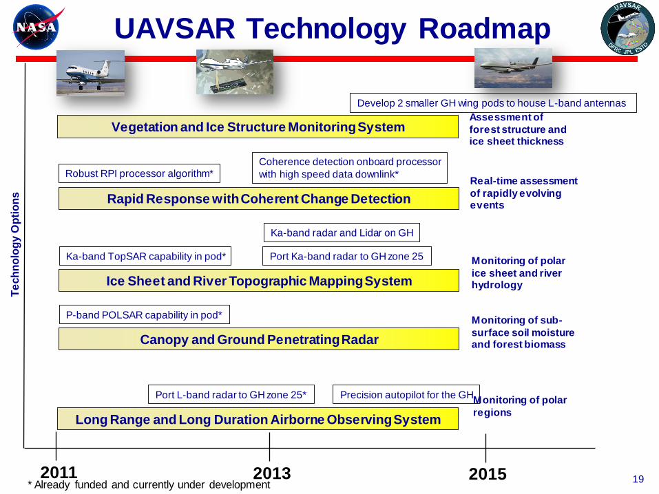
UAVSAR Technology Roadmap
19 2011 2013 2015
Port L-band radar to GH zone 25* Precision autopilot for the GH
Develop 2 smaller GH wing pods to house L-band antennas
P-band POLSAR capability in pod*
Ka-band TopSAR capability in pod* Port Ka-band radar to GH zone 25
Ka-band radar and Lidar on GH
Coherence detection onboard processor
with high speed data downlink*
Te
ch
no
log
y O
pti
on
s
Long Range and Long Duration Airborne Observing System
Canopy and Ground Penetrating Radar
Ice Sheet and River Topographic Mapping System
Rapid Response with Coherent Change Detection
Robust RPI processor algorithm*
Vegetation and Ice Structure Monitoring System Assessment of
forest structure and ice sheet thickness
Real-time assessment
of rapidly evolving events
Monitoring of polar
ice sheet and river hydrology
Monitoring of sub-
surface soil moisture and forest biomass
Monitoring of polar
regions
* Already funded and currently under development
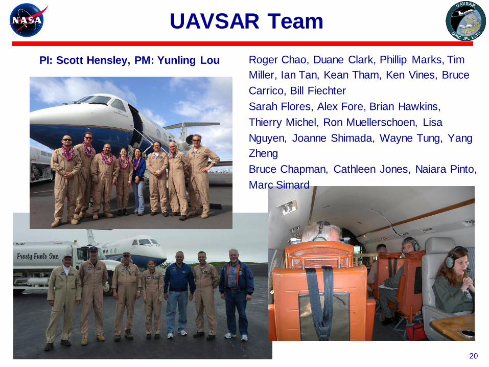
UAVSAR Team
20
PI: Scott Hensley, PM: Yunling Lou Roger Chao, Duane Clark, Phillip Marks, Tim
Miller, Ian Tan, Kean Tham, Ken Vines, Bruce
Carrico, Bill Fiechter
Sarah Flores, Alex Fore, Brian Hawkins,
Thierry Michel, Ron Muellerschoen, Lisa
Nguyen, Joanne Shimada, Wayne Tung, Yang
Zheng
Bruce Chapman, Cathleen Jones, Naiara Pinto,
Marc Simard