type test summary report - labss report iec:en... · (iec 60335-2-80) p fans marked with an ambient...
TRANSCRIPT

Page 1 of 22
Issue A November 2011 IEC/EN 60335-2-80A
Type Test Summary Report
Lab Ref; Trackit Ref
Product: RESPONSE 404535 (dMEV), 404876 (TP), 404877 (HTP)
Date: 18-04-2013
Product Ratings: 220-240V ~ 50Hz 6.2W IPX4
Test Engineer: DN
Key Observation Points;
Comment Accepted Y / N
Catalogue Literature accuracy
- Power OK Y
- Performance OK Y
- Data General Ok Y
Packaging Quality Good Y
- Quality of Packing Product and Brand name, Product type and Ratings Y
- Carton Markings Good Y
- Carton Condition Good Y
- Product condition when unpacked. Good Y
Product Quality
- Scratches None Y
- Other Damage None Y
- moulding marks None Y
- Material Discoloration None Y
Screws Tight Yes Y
Adequate Instructions for Use
- Correct Safety advice Yes Y
- Wiring instructions Yes Y
- Installation Detail Fully dimensioned and described Y
- Servicing Regular cleaning advised Y
Product CE marked Yes Y

Page 2 of 22
Issue A November 2011 IEC/EN 60335-2-80A
General Key Safety Point Check.
VOLUTION
HOLDINGS LIMITED
Type Test Summary Report
Vent-Axia Ltd
Fleming Way
Crawley
West Sussex. RH10 9YX
England
Product: RESPONSE 404535 (dMEV), 404876 (TP), 404877 (HTP)
Standard Assessed to:- IEC / EN 60335-1:2002, Amendments No: A11: 2004,
A1: 2004, A12: 2006, A2: 2006, A13:2008 and A14:2010
Standard tested to:- IEC / EN 60335-2-80:2003 Amendments No: A1:2004, A2:2009 SMT report reference:- LR 5457
Technical Data
Supporting photographic evidence of units under test

Page 3 of 22
Issue A November 2011 IEC/EN 60335-2-80A
Assessment Report IEC/EN 60335-1
Safety of household and similar electrical appliances
Considering Part 2: particular requirements for fans
Laboratory Test Reference No. ....... : LR 5457
Date of issue .................................... : 18-04-13
Testing Laboratory ........................ : Vent-Axia
Address ............................................ : Fleming Way, Crawley, West Sussex, RH10 9YX
Model/Type reference ...................... : 404535 (dMEV), 404876 (TP), 404877 (HTP)
Ratings: 220-240V ~ 50Hz 6.2W IPX4
Copy of marking plate and summary of test results (information/comments):
Test item particulars:
Classification of installation and use ............................ : Class II
Supply Connection ....................................................... : ~
...................................................................................... :
...................................................................................... :
Possible test case verdicts:
- test object does meet the requirement ....................... : P(Pass)
-test not relevant ........................................................... : N(Not Applicable)
- test object does not meet the requirement ................. : F(Fail)
Date (s) of performance of tests ................................... :

Page 4 of 22
Issue A November 2011 IEC/EN 60335-2-80A
5 GENERAL CONDITIONS FOR THE TESTS —
5.7 Fans intended to be used in tropical climates, tests of clauses 10, 11 and 13 are carried out at 40 °C +/- 2 °C (IEC 60335-2-80)
P
Fans marked with an ambient operating temperature, tests of clauses 10, 11 and 13 are carried out at the marked value +/- 2 °C (IEC 60335-2-80)
N
6 CLASSIFICATION —
6.1 Protection against electric shock: Class 0, 01, I, II or III:
CLASS II P
6.2 Duct fans shall be at least IP X2 (IEC 60335-2-80) N
6.101 Classification to climatic conditions : temperature climates,
tropical climates (IEC 60335-2-80)
P
7 —
7.1 Rated voltage or voltage range (V) ......................... : 220 – 240v P
Single-phase appliances: 230V covered: (EN 60335-1/A1)
P
Multi-phase appliance: 400V covered: (EN 60335-1/A1)
N
Nature of supply ....................................................... : ~ P
Rated frequency (Hz)............................................... : 50Hz P
Rated power input (W): ............................................ : 6.2W P
Rated current (A) .................................................... : N
Manufacturer's or responsible vendor's name, trademark or
identification mark .................................................... :
Vent-Axia Crawley P
Model or type reference ........................................... : 404535 (dMEV), 404876 (TP), 404877 (HTP)
P
Symbol 5172 of IEC 60417, for Class II appliances
P
IP number, other than IPX0 ..................................... : IPX4 P
For tropical climates marked with letter T
(EN 60335-2-80:2003)
N
Fans operating at local temperature exceeding 40 °C
marked with ambient operating temperature
(IEN 60335-2-80:2003)
P
7.3 Range of rated values marked with the lower and upper
limits separated by a hyphen
220 – 240V P
7.6 Correct symbols used P
7.7 Connection diagram fixed to appliances to be connected to
more than two supply conductors and appliances for
multiple supply
N
7.8 Except for type Z attachment, terminals for connection to the supply mains indicated as follows:

Page 5 of 22
Issue A November 2011 IEC/EN 60335-2-80A
- marking of terminals exclusively for the neutral conductor
(N)
P
- marking of protective earthing terminals (symbol 5019 of
IEC 60417)
P
- marking not placed on removable parts P
7.9 Marking or placing of switches which may cause a hazard N
7.10 Indications of switches on stationary appliances and
controls on all appliances by use of figures, letters or other
visual means ............................................................ :
N
The figure 0 indicates only OFF position, unless no
confusion with the OFF position
N
7.11 Indication for direction of adjustment of controls Timer, humidity P
7.12 Instructions for safe use provided P
This appliance is not intended for use by persons (including Children) with reduced physical sensory or mental capabilities, or lack of experience and knowledge, unless supervision or instruction is given in use of the appliance. (EN 60335-1 A2:2006)
P
If the instructions state that the guard has to be removed for
cleaning purposes. Ensure the fan is switched off from the
supply mains before removing the guard. (EN
60335-2-80:2003)
N
7.12.1 Sufficient details for installation supplied P
The installation instructions shall include the substance of the following (EN 60335-2-80:2003)
- the model or type reference of a luminaire that may be
installed in a fan constructed for this purpose;
N
- whether the fan is intended for mounting in outside
windows or walls (partition fans);
N
- that the fan is to be installed so that the blades are more
than 2,3 m above the floor (for fans intended to be mounted
at high level);
N
- that precautions must be taken to avoid the back flow of
gases into the room from the open flue of gas or other fuel-
burning appliances (for duct and partition fans).
P
7.12.2 Stationary appliances not fitted with means for
disconnection from the supply mains having a contact
separation in all poles that provide full disconnection under
overvoltage category III, the instructions state that means
for disconnection must be incorporated in the fixed wiring in
accordance with the wiring rules
P
7.12.3 Insulation of the fixed wiring in contact with parts exceeding
50 K during clause 11; instructions stating that the fixed
wiring must be protected
N
7.12.4 Instructions for built-in appliances:
- dimensions of space N
- dimensions and position of supporting means N
- distances between parts and surrounding structure N

Page 6 of 22
Issue A November 2011 IEC/EN 60335-2-80A
- dimensions of ventilation openings and arrangement N
- connection to supply mains and interconnection of
separate components
N
- necessity to allow disconnection of the appliance from
the supply after installation, unless the appliance
incorporates a switch complying with 24.3.
(IEC 60335-1/A1)
N
The disconnection may be achieved by having the plug
accessible or by incorporating a switch in the fixed wiring
in accordance with the wiring rules. (IEC 60335-1/A1)
N
7.12.5 Replacement cord instructions, type X attachment with a
specially prepared cord
N
Replacement cord instructions, type Y attachment N
Replacement cord instructions, type Z attachment N
7.12.6 The instructions for heating appliances incorporating a non-self-resetting thermal cut-out that is reset by disconnection of the supply mains shall contain the substance of the following: (IEC 60335-1/A1)
CAUTION: In order to avoid a hazard due to inadvertent
resetting of the thermal cutout, this appliance must not be
supplied through an external switching device, such as a
timer, or connected to a circuit that is regularly switched
on and off by the utility. (IEC 60335-1/A1)
N
7.12.7 The instructions for fixed appliances shall state how the
appliance is to be fixed to its support. (IEC 60335-1/A1)
P
7.13 Instructions and other texts in an official language P
7.14 Marking clearly legible and durable P
7.15 Marking on a main part P
Marking clearly discernible from the outside, if necessary
after removal of a cover
P
For portable appliances, cover can be removed or opened
without a tool
N
For stationary appliances, name, trademark or identification
mark and model or type reference visible after installation
N
For fixed appliances, name, trademark or identification
mark and model or type reference visible after installation
according to the instructions
P
Indications for switches and controls placed on or near the
components. Marking not on parts which can be positioned
or repositioned in such a way that the marking is misleading
P
8 PROTECTION AGAINST ACCESS TO LIVE PARTS —
8.1 Adequate protection against accidental contact with live
parts
P
8.1.1 Requirement applies for all positions, detachable parts
removed
P

Page 7 of 22
Issue A November 2011 IEC/EN 60335-2-80A
Lamps are not removed, protection against contact with live
parts of the lamp cap shall be ensured. (EN
60335-2-80:2003)
N
Use of test probe B of IEC 61032: no contact with live parts
8.1.2 Use of test probe 13 of IEC 61032 through openings in
class 0 appliances and class II appliances/ constructions:
no contact with live parts
P
Test probe 13 also applied through openings in earthed
metal enclosures having a non-conductive coating: no
contact with live parts
N
8.1.3 For appliances other than class II, use of test probe 41 of IEC 61032: no contact with live parts of visible glowing heating elements
N
8.1.4 Accessible part not considered live if:
- The part is supplied at safety extra-low provided that N
- for a.c. voltage: peak value not exceeding 42.4 V N
- safety extra-low d.c. voltage: not exceeding 42.4 V N
- or separated from live parts by protective impedance N
- for voltages having a peak value over 15 kV, the energy in
the discharge shall not exceed 350 mJ (IEC
60335-1:A2)
N
If protective impedance: d.c. current not exceeding 2 mA,
and
N
a.c. peak value not exceeding 0.7 mA N
- for peak values over 42.4 V up to and including 450 V,
capacitance not exceeding 0,1 F
N
- for peak values over 450 V up to and including 15 kV,
discharge not exceeding 45 C
N
The quantity of electricity in the discharge is measured
using a resistor having a nominal non-inductive resistance
of 2 000 Ω (IEC 60335-1/A1)
N
8.1.5 Live parts protected at least by basic insulation before installation or assembly: —
- built-in appliances N
- fixed appliances P
- appliances delivered in separate units N
8.2 Class II appliances and constructions constructed so that
there is adequate protection against accidental contact with
basic insulation and metal parts separated from live parts
by basic insulation only
P
Only possible to touch parts separated from live parts by
double or reinforced insulation
P
Removal of detachable parts after user maintenance,
basic insulation may be touched provided that wiring is
electrically equivalent with IEC 60227 or IEC 60245
(EN 60335-2-80:2003)
P

Page 8 of 22
Issue A November 2011 IEC/EN 60335-2-80A
9 STARTING OF MOTOR-OPERATED APPLIANCES —
Requirements and tests are specified in part 2 when
necessary
N
10 POWER INPUT AND CURRENT —
10.1 Power input at normal operating temperature, rated voltage
and normal operation not deviating from rated power input
by more than shown in table 1 The permissible deviations
apply for both limits of the range for the appliance marked
with a rated voltage range. (IEC 60335-1, A2:2006
P
10.2 Current at normal operating temperature, rated voltage and
normal operation not deviating from rated current by more
than shown in table 2 The permissible deviations apply for
both limits of the range for the appliance marked with a
rated voltage range. (IEC 60335-1, A2:2006)
N
Appliances are tested with shutters of similar devices in the
open position (EN 60335-2-80:2003)
N
11 HEATING —
11.1 No excessive temperatures in normal use P
11.3 Temperature rises, other than of windings, determined by
thermocouples
P
Temperature rises of windings determined by resistance
method, where possible
N
11.4 Heating appliances operated under normal operation at
1.15 times rated power input .................................. :
N
11.5 Motor-operated appliances operated under normal
operation at most unfavourable voltage between 0.94 and
1.06 times rated voltage .......................................... :
P
11.6 Combined appliances operated under normal operation at most unfavourable voltage between 0.94 and 1.06 times rated voltage:
N
Appliances are operated until steady conditions are established. (EN 60335-2-80:2003)
N
Appliances without a timer are operated -
11.8 Temperature rises not exceeding values in table 3 N
Protective devices do not operate N
The temperature rise limits for appliances for tropical
climates are reduced by 15K. (EN 60335-2-80:2003)
N
The temperature rise limits for fans marked with an ambient
operating temperature are reduced by the difference
between the marked value and 25 ºC. (EN 60335-2-
80:2003)
N

Page 9 of 22
Issue A November 2011 IEC/EN 60335-2-80A
13 LEAKAGE CURRENT AND ELECTRIC STRENGTH AT OPERATING TEMPERATURE —
13.1 Leakage current not excessive and electric strength
adequate
P
Heating appliances operated at 1.15 times rated power
input .......................................................................... :
N
Motor-operated appliances and combined appliances
supplied at 1.06 times rated voltage ....................... :
P
Protective impedance and radio interference filters
disconnected before carrying out the tests
N
13.2 Leakage current measured by means of the circuit
described in figure 4 of IEC 60990
P
Leakage current measurements (see appended table) P
13.3 The appliance is disconnected from the supply and the
insulation is immediately subjected to a voltage having a
frequency of 50 Hz or 60 Hz for 1 min, in accordance with
IEC 61180-1. (IEC 60335-1/A1)
P
The high-voltage source used for the test is to be capable
of supplying a short circuit current Is between the output
terminals after the output voltage has been adjusted to the
appropriate test voltage. (IEC 60335-1/A1)
P
No breakdown during the tests P
15 MOISTURE RESISTANCE —
15.1 Enclosure provides the degree of moisture protection
according to classification of the appliance
P
No trace of water on insulation which can result in a
reduction of clearances and creepage distances below
values specified in clause 29
P
16 LEAKAGE CURRENT AND ELECTRIC STRENGTH —
16.1 Leakage current not excessive and electric strength
adequate
P
Protective impedance disconnected from live parts before
carrying out the tests
N
16.2 Single-phase appliances: test voltage 1.06 times rated
voltage ...................................................................... :
P
Three-phase appliances: test voltage 1.06 times rated
voltage divided by 3 ............................................... :
N
Leakage current measurements P
16.3 Electric strength tests according to IEC 61180-1 the values of the test voltages as specified in table 7. (IEC 60335-1, A2:2006)
P
No breakdown during the tests P

Page 10 of 22
Issue A November 2011 IEC/EN 60335-2-80A
17 OVERLOAD PROTECTION OF TRANSFORMERS AND ASSOCIATED CIRCUITS —
No excessive temperatures in transformer or associated
circuits in event of short-circuits likely to occur in normal use
(see appended table) N
Appliance supplied with 1.06 or 0.94 times rated voltage
and the most unfavourable short-circuit or overload likely to
occur in normal use applied .................................... :
N
Temperature rise of insulation of the conductors of safety
extra-low voltage circuits not exceeding the relevant value
specified in table 3 by more than 15 K
N
Temperature of the winding not exceeding the value
specified in table 8,
N
however limits do not apply to fail-safe transformers
complying with sub-clause 15.5 of IEC 61558-1
N
18 ENDURANCE —
Requirements and tests are specified in part 2 when
necessary
N
19 ABNORMAL OPERATION —
19.1 The risk of fire or mechanical damage under abnormal or
careless operation obviated
P
Electronic circuits so designed and applied that a fault will
not render the appliance unsafe
P
19.2 Test of appliance with heating elements with restricted heat
dissipation; test voltage (V): power input of 0.85 times rated
power input ............................................................... :
N
19.3 Test of 19.2 repeated; test voltage (V): power input of
1.24 times rated power input ................................... :
N
19.7 Stalling test by locking the rotor if the locked rotor torque is
smaller than the full load torque or locking moving parts of
other appliances
N
Locked rotor, motor capacitors open-circuited or short-
circuited, if required
N
Locked rotor, capacitors open-circuited one at a time N
Test repeated with capacitors short-circuited one at a time, if required unless they are of class P2 of IEC 60252-1 (IEC 60335-1, A2: 2006)
N
Other appliances are supplied at rated voltage for a period:
- of 5 min for other appliances that are operated while
attended
N
- until steady conditions are established for other
appliances.
N
Winding temperatures not exceeding values specified in
table 8 (EN 60335-2-80:2003)
(see appended table) N
- 50 K, for appliances with T marking N
- 65 K, for other appliances N

Page 11 of 22
Issue A November 2011 IEC/EN 60335-2-80A
19.8 Three-phase motors operated at rated voltage with one
phase disconnected
N
19.9 Running overload test on appliances incorporating motors that are intended to be remotely or automatically controlled or liable to be operated continuously.
N
19.13 During the tests the appliance does not emit flames, molten
metal, poisonous or ignitable gas in hazardous amounts
P
Temperature rises not exceeding the values shown in
table 9
(see appended table) P
After the tests, and when the appliance has cooled to approximately room temperature, compliance with cl. 8 shall not be impaired and the appliance shall comply with 20.2 if it can still be operated (IEC 60335-1, A2)
N
19.101 Fans incorporating shutters or similar that are operated
automatically are supplied at rated voltage in the closed or
open position, whichever is more unfavourable (EN
60335-2-80:2003)
N
20 STABILITY AND MECHANICAL HAZARDS —
20.1 Adequate stability N
Tilting test through an angle of 10 (appliance placed on an
inclined plane/horizontal plane); appliance does not
overturn
N
Tilting test repeated on appliances with heating elements,
angle of inclination increased to 15
N
Possible heating test in overturned position; temperature
rise does not exceed values shown in table 9
N
Portable pedestal fans exceeding 1,7 m and exceeding 10
kg tested with a force of 40 N at 1,5 m (IEC
60335-2-80:2003)
N
20.2 Moving parts adequately arranged or enclosed as to
provide protection against personal injury
P
Protective enclosures, guards and similar parts are non-
detachable
P
Adequate mechanical strength and fixing of protective
enclosures
P
Self-resetting thermal cut-outs and overcurrent protective
devices not causing a hazard, by unexpected reclosure
N
Not possible to touch dangerous moving parts with test
probe
P
20.101 Fan blades, other than those for mounting at high level, shall be guarded, unless. (IEC
60335-2-80:2002)
-
- they have a hardness less than D 60 Shore, or
- they have a peripheral speed less than 15m/s when the
fan is supplied at rated voltage, or P
- the fan has a power output not exceeding 2W when
supplied at rated voltage. N

Page 12 of 22
Issue A November 2011 IEC/EN 60335-2-80A
21 MECHANICAL STRENGTH —
21.1 Appliance has adequate mechanical strength and is
constructed as to withstand rough handling (IEC
60335-1/A1)
P
22 CONSTRUCTION —
22.1 Appliance marked with the first numeral of the IP system,
relevant requirements of IEC 60529 are fulfilled
N
22.8 Electrical connections not subject to pulling during cleaning
of compartments to which access can be gained without the
aid of a tool, and that are likely to be cleaned in normal use
P
22.11 Reliable fixing of non-detachable parts that provide the
necessary degree of protection against electric shock,
moisture or contact with moving parts
P
Obvious locked position of snap-in devices used for fixing
such parts
N
22.14 No ragged or sharp edges creating a hazard for the user in
normal use, or during user maintenance
P
No exposed pointed ends of self tapping screws etc., liable
to be touched by the user in normal use or during user
maintenance
P
22.18 Current-carrying parts and other metal parts resistant to
corrosion under normal conditions of use
P
22.20 Direct contact between live parts and thermal insulation
effectively prevented, unless material used is non-corrosive,
non-hygroscopic and non-combustible
N
Compliance is checked by inspection and, if necessary, by
appropriate test
N
22.21 Wood, cotton, silk, ordinary paper and fibrous or hygroscopic material not used as insulation, unless impregnated. Does not apply to magnesium oxide and mineral ceramic fibres used for insulation of heating elements (IEC EN60335-1: A2)
P
22.22 Appliances not containing asbestos P
22.24 Bare heating elements adequately supported N
In case of rupture, the heating conductor is unlikely to come
in contact with accessible metal parts
N
22.25 Sagging heating conductors cannot come into contact with
accessible metal parts
N
22.29 Class II appliances permanently connected to fixed wiring
so constructed that the required degree of access to live
parts is maintained after installation
P
22.30 Parts serving as supplementary or reinforced insulation
fixed so that they cannot be removed without being
seriously damaged, or
P
so constructed that they cannot be replaced in an incorrect
position, and so that if they are omitted, the appliance is
rendered inoperable or manifestly incomplete
N

Page 13 of 22
Issue A November 2011 IEC/EN 60335-2-80A
Insulating material in which heating conductors are
embedded is considered to be basic insulation and not
reinforced insulation. (IEC 60335-1:A2)
N
23 INTERNAL WIRING —
23.1 Wireways smooth and free from sharp edges P
Wires protected against contact with burrs, cooling fins etc. P
Wire holes in metal well rounded or provided with bushings N
Wiring effectively prevented from coming into contact with
moving parts
P
23.5 The insulation of internal wiring withstanding the electrical
stress likely to occur in normal use
P
No breakdown when a voltage of 2000 V is applied for
15 min between the conductor and metal foil wrapped
around the insulation
P
23.6 Sleeving used as supplementary insulation on internal
wiring retained in position by positive means
N
23.7 The colour combination green/yellow used only for earthing
conductors
N
23.8 Aluminium wires not used for internal wiring P
23.9 No lead-tin soldering of stranded conductors where they
are subject to contact pressure, unless
N
clamping means so constructed that there is no risk of bad
contact due to cold flow of the solder
N
24.3 Switches intended for all-pole disconnection of stationary
appliances are directly connected to the supply terminals
and having a contact separation in all poles, providing full
disconnection under overvoltage category III conditions
N
24.4 Plugs and socket-outlets for extra-low voltage circuits and
heating elements, not interchangeable with plugs and
socket-outlets listed in IEC 60083 or IEC 60906-1 or with
connectors and appliance inlets complying with the
standard sheets of IEC 60320-1
N
24.5 Capacitors in auxiliary windings of motors marked with their
rated voltage and capacitance and used accordingly
N
Voltage across capacitors in series with a motor winding
does not exceed 1,1 times rated voltage, when the
appliance is supplied at 1,1 times rated voltage under
minimum load
N
24.101 Thermal cut-outs incorporated in duct fans in order to
comply with clause 19 shall not be self-resetting.
(EN 60335-2-80:2003)
N
25 SUPPLY CONNECTION AND EXTERNAL FLEXIBLE CORDS —
25.1 Appliance not intended for permanent connection to fixed wiring, means for
connection to the supply:
—

Page 14 of 22
Issue A November 2011 IEC/EN 60335-2-80A
- supply cord fitted with a plug N
- an appliance inlet having at least the same degree of
protection against moisture as required for the appliance
N
- pins for insertion into socket-outlets N
25.3 Connection of supply conductors for appliance intended to
be permanently connected to fixed wiring possible after the
appliance has been fixed to its support
P
Appliance provided with a set of terminals for the
connection of cables or fixed wiring, cross-sectional areas
specified in 26.6
N
Appliance provided with a set of terminals allowing the
connection of a flexible cord
P
Appliance provided with a set of supply leads
accommodated in a suitable compartment
N
Appliance provided with a set of terminals and cable
entries, conduit entries, knock-outs or glands, allowing
connection of appropriate type of cable or conduit
N
25.9 Supply cord not in contact with sharp points or edges P
25.10 Green/yellow core for earthing purposes in Class I
appliance
N
25.11 Conductors of supply cords not consolidated by lead-tin
soldering where they are subject to contact pressure,
unless
P
clamping means so constructed that there is no risk of bad
contacts due to cold flow of the solder
N
25.13 Inlet opening so shaped as to prevent damage to the
supply cord
P
Unless the enclosure at the inlet opening is of insulation
material, a non-detachable lining or bushing complying with
29.3 for supplementary insulation provided
N
25.15 Conductors of the supply cord relieved from strain, twisting
and abrasion by use of cord anchorage
P
The cord cannot be pushed into the appliance to such an
extent that the cord or internal parts of the appliance can be
damaged
P
25.16 Cord anchorages for type X attachments constructed and located so that:
- cord cannot touch the clamping screws of cord anchorage
if these screws are accessible, unless separated from
accessible metal parts by supplementary insulation
N
- the cord is not clamped by a metal screw which bears
directly on the cord
P
- at least one part of the cord anchorage securely fixed to
the appliance, unless part of a specially prepared cord
P
- screws which have to be operated when replacing the
cord do not fix any other component, if applicable
N
- if labyrinths can be bypassed the test of 25.15 is
nevertheless withstood
N

Page 15 of 22
Issue A November 2011 IEC/EN 60335-2-80A
- for Class 0, 0I and I appliances: they are of insulating
material or are provided with an insulating lining, unless a
failure of the insulation of the cord does not make
accessible metal parts live
N
- for Class II appliances: they are of insulating material, or if
of metal, they are insulated from accessible metal parts by
supplementary insulation
P
25.18 Cord anchorages only accessible with the aid of a tool, or P
so constructed that the cord can only be fitted with the aid
of a tool
P
25.19 Type X attachment, glands not used as cord anchorage in
portable appliances
N
Tying the cord into a knot or tying the cord with string not
used
N
25.20 Conductors of the supply cord for type Y and Z attachment
adequately additionally insulated
N
25.21 Space for supply cord for type X attachment or for
connection of fixed wiring constructed to permit checking of
conductors with respect to correct positioning and
connection before fitting any cover, no risk of damage to the
conductors when fitting the cover, no contact with
accessible metal parts if a conductor becomes loose, etc.
P
For portable appliances, the uninsulated end of a conductor
prevented from any contact with accessible metal parts,
unless the end of the cord is such that the conductors are
unlikely to slip free
N
26 TERMINALS FOR EXTERNAL CONDUCTORS —
26.1 Appliances provided with terminals or equally effective
devices for connection of external conductors
P
Terminals only accessible after removal of a non-
detachable cover
P
However, earthing terminals may be accessible if a tool is
required to make the connections and means are provided
to clamp the wire independently from its connection.
(IEC 60335-1/A1)
N
If soldered connections used, the conductor so positioned
or fixed that reliance is not placed on soldering alone
N
Soldering alone used, barriers provided, clearances and
creepage distances satisfactory if the conductor becomes
free at the soldered joint
N
26.3 Terminals for type X attachment and for connection to fixed
wiring so constructed that the conductor is clamped
between metal surfaces with sufficient contact pressure and
without damaging the conductor
P
Terminals for type X attachment and those for connection to fixed wiring so fixed
that when tightening or loosening the clamping means:
—

Page 16 of 22
Issue A November 2011 IEC/EN 60335-2-80A
26.4 Terminals for type X attachment, except those with a
specially prepared cord, and those for connection to fixed
wiring, no special preparation of conductors required, and
so constructed or placed that conductors prevented from
slipping out
P
No contact between live parts and accessible metal parts
and, for class II constructions, between live parts and metal
parts separated from accessible metal parts by
supplementary insulation only
P
26.7 Terminals for type X attachment accessible after removal of
a cover or part of the enclosure
P
26.8 Terminals for the connection to fixed wiring, including the
earthing terminal, located close to each other
P
26.9 Terminals of the pillar type constructed and located as
specified
P
26.10 Terminals with screw clamping and screwless terminals not
used for flat twin tinsel cords, unless conductors ends fitted
with a device suitable for screw terminals
N
Pull test of 5 N to the connection N
26.11 For type Y and Z attachment: soldered, welded, crimped
and similar connections may be used
N
For Class II appliances: the conductor so positioned or fixed
that reliance is not placed on soldering, welding or crimping
alone
N
For Class II appliances: soldering, welding or crimping
alone used, barriers provided, clearances and creepage
distances satisfactory if the conductor becomes free
N
27 PROVISION FOR EARTHING —
27.1 Accessible metal parts of Class 0I and I appliances,
permanently and reliably connected to an earthing terminal
or contact of the appliance inlet
N
Earthing terminals not connected to neutral terminal N
Class 0, II and III appliance have no provision for earthing P
Safety extra-low voltage circuits not earthed, unless
protective extra-low voltage circuits
N
27.2 Clamping means adequately secured against accidental
loosening
N
Conductors cannot be loosened without the aid of a tool N
27.3 If a detachable part having an earth connection is plugged
into another part of the appliance, the earth connection
shall be made before the current-carrying connections are
established. The current-carrying connections shall be
separated before the earth connection when removing the
part. (IEC 60335-1/A1)
N
For appliances with supply cord, current-carrying
conductors become taut before earthing conductor, if the
cord slips out of the cord anchorage
N

Page 17 of 22
Issue A November 2011 IEC/EN 60335-2-80A
27.4 No risk of corrosion resulting from contact between metal of
earthing terminal and other metal
N
Adequate resistance to corrosion of coated or uncoated
parts providing earthing continuity, other than parts of a
metal frame or enclosure
N
Parts of steel providing earthing continuity provided at the
essential areas with an electroplated coating, thickness at
least 5 µm
N
Adequate protection against rusting of parts of coated or
uncoated steel, only intended to provide or transmit contact
pressure
N
In case of aluminium alloys precautions taken to avoid risk
of corrosion
N
27.5 Low resistance of connection between earthing terminal
and earthed metal parts
N
This requirement does not apply to connections providing
earthing continuity in the protective extra-low voltage circuit,
provided that clearances of basic insulation are based on
the rated voltage of the appliance
N
Resistance not exceeding 0,1 Ω at the specified low-
resistance test
N
27.6
The printed conductors of printed circuit boards not used to provide earthing continuity in hand held appliances. They may be used to provide earthing continuity in other appliances if at least two tracks are used with independent soldering points and the appliance complies with requirements of 27.5 for each circuit. (IEC 60335-1: A2)
N
28 SCREWS AND CONNECTIONS —
28.1 Fixings, electrical connections and connections providing
earthing continuity withstand mechanical stresses
N
Screws not of soft metal liable to creep, such as zinc or
aluminium
P
Diameter of screws of insulating material min. 3 mm N
Screws of insulating material not used for any electrical
connection or connections providing earthing continuity
N
Screws used for electrical connections or connections
providing earthing continuity screw into metal
N
Screws not of insulating material if their replacement by a
metal screw can impair supplementary or reinforced
insulation
P
Type X attachment, screws to be removed for replacement
of supply cord or for user maintenance, not of insulating
material if their replacement by a metal screw can impair
basic insulation
N
For screws and nuts; test as specified N
28.2 Electrical connections and connections providing earthing
continuity constructed so that contact pressure not
transmitted through insulating material liable to shrink or
distort, unless shrinkage or distortion compensated
N

Page 18 of 22
Issue A November 2011 IEC/EN 60335-2-80A
This requirement does not apply to electrical connections in
circuits carrying a current not exceeding 0.5A
N
28.3 Space-threaded (sheet metal) screws only used for
electrical connections if they clamp the parts together
N
Thread-cutting (self-tapping) screws and thread rolling
screws shall only be used for electrical connections if they
generate a full form standard machine screw thread. (IEC
60335-1: A2)
N
Thread-cutting, thread rolling and space-threaded screws may be used in connections providing earthing continuity provided it is not necessary to disturb the connection:
—
- in normal use, (IEC 60335-1: A2) N
- during user maintenance, (IEC 60335-1: A2) N
- when replacing a supply cord having a type X attachment, or (IEC 60335-1: A2)
N
- during installation. (IEC 60335-1: A2) N
At least two screws must be used for each connection providing earthing continuity unless the screws forms a thread having a length of at least half the diameter of the screws (IEC 60335-1: A2)
N
28.4 Screws and nuts that make mechanical connection secured
against loosening if they also make electrical connections
or connections providing earthing continuity
N
Rivets for electrical connections or connections providing
earthing continuity secured against loosening if subjected to
torsion
N
30 RESISTANCE TO HEAT AND FIRE —
30.1 External parts of non-metallic material, P
parts supporting live parts, and P
thermoplastic material providing supplementary or
reinforced insulation,
P
sufficiently resistant to heat P
30.2 Relevant parts of non-metallic material adequately resistant
to ignition and spread of fire (IEC 60335-1: A2)
P
30.2.1 Parts of non-metallic material are subjected to the Glow-
wire test of IEC 60695-2-11 at 550 C, (IEC 60335-1: A2)
P
30.2.2 Appliances operated while attended, parts of insulating material supporting current-
carrying connections and parts within a distance of 3mm subjected to the glow-wire
test of IEC 60695-2-11 at a temperature of: (IEC 60335-1: A2)
—
- 750C, for connections carrying a current exceeding 0,5A
during normal operation (IEC 60335-1: A2)
P
- 650C, for other connections (IEC 60335-1: A2) N
Test not applicable to conditions as specified (IEC
60335-1: A2)
N
30.2.3 Appliances operated while unattended, tested as specified
in 30.2.3.1 and 30.2.3.2 (IEC 60335-1: A2)
P

Page 19 of 22
Issue A November 2011 IEC/EN 60335-2-80A
Test not applicable to conditions as specified (IEC
60335-1: A2)
P
30.2.3.1 Parts of insulating material supporting connections carrying
a current exceeding 0.2A during normal operation, and (IEC
60335-1: A2)
P
parts of insulating material within a distance of 3mm, (IEC
60335-1: A2)
P
having a glow-wire flammability index of at least 850C
according to IEC 60695-2-12 (IEC 60335-1: A2)
30.2.3.2 Parts of insulating material supporting current-carrying
connections, and (IEC 60335-1: A2)
P
parts of insulating material within a distance of 3mm, P
subjected to glow-wire test of IEC 60695-2-11 (IEC
60335-1: A2)
P
Test not carried out on material having a glow-wire ignition
temperature according to IEC 60695-2-13 as specified (IEC
60335-1: A2)
N
Glow-wire test of IEC 60695-2-11, the temperature being:
- 750C, for connections carrying a current exceeding 0,2A
during normal operation (IEC 60335-1: A2)
P
- 650C, for other connections (IEC 60335-1: A2) N
Parts that during the test produce a flame persisting longer
than 2 s, tested as specified (IEC 60335-1: A2)
N
If a flame persists longer than 2 s during the test, parts
above the connection, as specified, subjected to the
needle-flame test of annex E, unless (IEC 60335-1: A2)
N
the material is classified as V-0 or V-1 according to IEC
60695-11-10 (IEC 60335-1: A2)
N
30.2.4 Base material of printed circuit boards subjected to needle-
flame test of annex E (IEC 60335-1: A2)
P
Test not applicable to conditions as specified (IEC
60335-1: A2)
N
31 RESISTANCE TO RUSTING —
Relevant ferrous parts adequately protected against rusting
32 RADIATION, TOXICITY AND SIMILAR HAZARDS —
Appliance does not emit harmful radiation or present a toxic
or similar hazard due to their operation in normal use. (IEC
60335-1: A2)
P
- 100, the mass of part does not exceed 250 g N
- 50, the mass of part exceeds 250 g N
After the test, the requirements of 8.1, 15.1.1, 16.3 and
clause 29 are met
N
Page 20 of 22
Issue A November 2011 IEC/EN 60335-2-80A
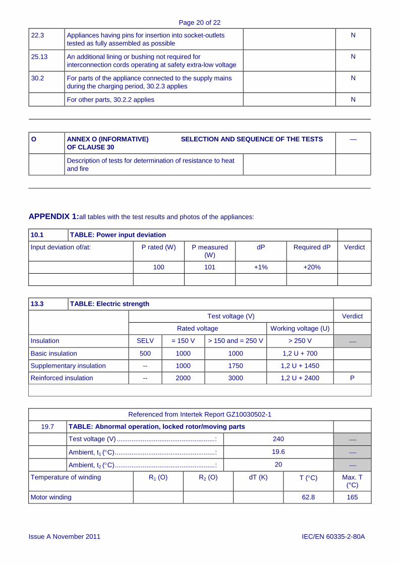
22.3 Appliances having pins for insertion into socket-outlets
tested as fully assembled as possible
N
25.13 An additional lining or bushing not required for
interconnection cords operating at safety extra-low voltage
N
30.2 For parts of the appliance connected to the supply mains
during the charging period, 30.2.3 applies
N
For other parts, 30.2.2 applies N
O ANNEX O (INFORMATIVE) SELECTION AND SEQUENCE OF THE TESTS
OF CLAUSE 30
—
Description of tests for determination of resistance to heat
and fire
APPENDIX 1:all tables with the test results and photos of the appliances:
10.1 TABLE: Power input deviation
Input deviation of/at: P rated (W) P measured (W)
dP Required dP Verdict
100 101 +1% +20%
13.3 TABLE: Electric strength
Test voltage (V) Verdict
Rated voltage Working voltage (U)
Insulation SELV = 150 V > 150 and = 250 V > 250 V
Basic insulation 500 1000 1000 1,2 U + 700
Supplementary insulation -- 1000 1750 1,2 U + 1450
Reinforced insulation -- 2000 3000 1,2 U + 2400 P
Referenced from Intertek Report GZ10030502-1
19.7 TABLE: Abnormal operation, locked rotor/moving parts
Test voltage (V) ..................................................... : 240
Ambient, t1 (C) ...................................................... : 19.6
Ambient, t2 (C) ...................................................... : 20
Temperature of winding R1 (O) R2 (O) dT (K) T (C) Max. T (°C)
Motor winding 62.8 165

Page 21 of 22
Issue B August 2010 IEC/EN 60335-2-80A
TABLE 30 RESISTANCE TO HEAT, FIRE AND TRACKING (appended table)
Component Manufacturer Type Ball pressure test Tracking test
[CTI/ PTI]
Glow wire test Needle- flame test
Verdict
75°C cl. 11 +40°C
125°C cl. 19 +25°C
GWT550°C
GWT650°C
GWT750°C
GWFI 850°C
GWIT
Enclosure No Flame
PCB Fan No Flame
Terminal Block No Flame
No Flame
PCB Motor No Flame
1) surrounding parts are subjected to the needle-flame test of Annex E

Page 22 of 22
Issue B August 2010 IEC/EN 60335-2-80A
Motor class = E Maximum temp during test = 53.4˚C maximum normal temperature rises = 80˚C Verdict = Pass
PCB FRONT
Back of PCB
0
10
20
30
40
50
60
11
:14
:50
11
:24
:50
11
:34
:50
11
:44
:50
11
:54
:50
12
:04
:50
12
:14
:50
12
:24
:50
12
:34
:50
12
:44
:50
12
:54
:50
13
:04
:50
13
:14
:50
13
:24
:50
13
:34
:50
13
:44
:50
13
:54
:50
14
:04
:50
14
:14
:50
14
:24
:50
14
:34
:50
TEM
PER
ATU
RE°
C
TIME
RESPONSE FAN TEMPERATURE RISE
Ambient Motor Winding