type: pxz operation manual - cd automation · pdf fileoperation ... program status display ......
TRANSCRIPT

Micro controller X
Type: PXZ
OPERATION MANUAL
PXZ-1-E
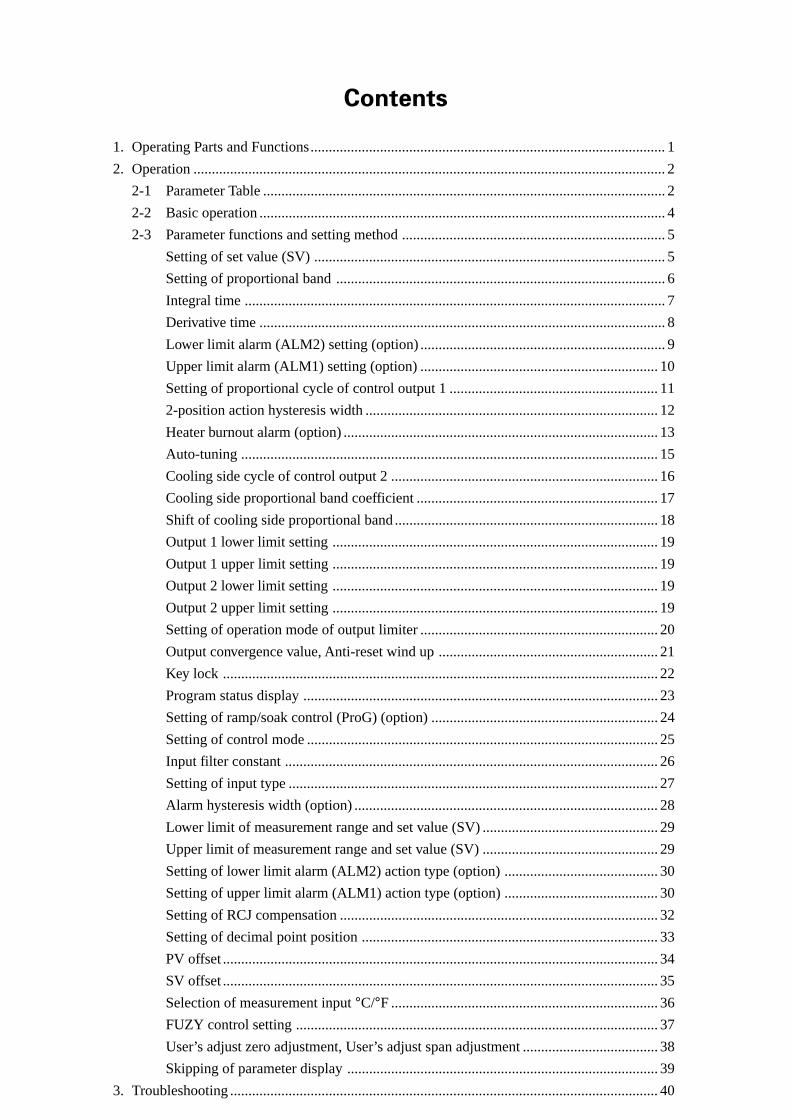
Contents
1. Operating Parts and Functions................................................................................................. 1
2. Operation ................................................................................................................................. 2
2-1 Parameter Table .............................................................................................................. 2
2-2 Basic operation ............................................................................................................... 4
2-3 Parameter functions and setting method ........................................................................ 5
Setting of set value (SV) ................................................................................................ 5
Setting of proportional band .......................................................................................... 6
Integral time ................................................................................................................... 7
Derivative time ............................................................................................................... 8
Lower limit alarm (ALM2) setting (option) ................................................................... 9
Upper limit alarm (ALM1) setting (option) ................................................................. 10
Setting of proportional cycle of control output 1 ......................................................... 11
2-position action hysteresis width ................................................................................ 12
Heater burnout alarm (option) ...................................................................................... 13
Auto-tuning .................................................................................................................. 15
Cooling side cycle of control output 2 ......................................................................... 16
Cooling side proportional band coefficient .................................................................. 17
Shift of cooling side proportional band ........................................................................ 18
Output 1 lower limit setting ......................................................................................... 19
Output 1 upper limit setting ......................................................................................... 19
Output 2 lower limit setting ......................................................................................... 19
Output 2 upper limit setting ......................................................................................... 19
Setting of operation mode of output limiter ................................................................. 20
Output convergence value, Anti-reset wind up ............................................................ 21
Key lock ....................................................................................................................... 22
Program status display ................................................................................................. 23
Setting of ramp/soak control (ProG) (option) .............................................................. 24
Setting of control mode ................................................................................................ 25
Input filter constant ...................................................................................................... 26
Setting of input type ..................................................................................................... 27
Alarm hysteresis width (option) ................................................................................... 28
Lower limit of measurement range and set value (SV) ................................................ 29
Upper limit of measurement range and set value (SV) ................................................ 29
Setting of lower limit alarm (ALM2) action type (option) .......................................... 30
Setting of upper limit alarm (ALM1) action type (option) .......................................... 30
Setting of RCJ compensation ....................................................................................... 32
Setting of decimal point position ................................................................................. 33
PV offset ....................................................................................................................... 34
SV offset ....................................................................................................................... 35
Selection of measurement input °C/°F ......................................................................... 36
FUZY control setting ................................................................................................... 37
User’s adjust zero adjustment, User’s adjust span adjustment ..................................... 38
Skipping of parameter display ..................................................................................... 39
3. Troubleshooting ..................................................................................................................... 40

1
1Operating Parts and Functions
Fig. 1-1 shows the outline of the front panel of the unit.
One the front of the unit, there are PV/SV digital indication lamps, condition indication lamps and setting keys.
Table 1-1 shows the functions of these oeprating parts. Before using the unit, be sure to understand the functions
of the operating parts.
For details of setting parameters, refer to Chapter 2 of this manual.
CC1
PV
SV
C2 H HB L
PXZ-7
SEL DATA ENTSV
Control output 2 lamp
Control output 1 lamp
Alarm lamp
Heater burnout alarm lamp
SV lamp
DOWN key
100-digit UP key
SEL key
SV key
SV (set value) indicator
PV (measured value) indicator
Industrial value unit
1-digit UP key
10-digit UP key
DATA key
ENT key
Fig. 1-1
Table 1-1
Name Function
Control output 1 lamp Lights at ON of control output 1.
Control output 2 lamp Lights at ON of control output 2.
Alarm lamp Lights at alarm detection. Alarm output is ON at the same time.
Heater burnout alarm lamp Lights at detection of heater burnout.Heater burnout alarm output is ON at the same time.
PV (measured value) indicator Indicates measured values.
SV (set value) indicator Indicates set values. Also indicates parameters anddata at setting of parameters.
1-digit “ ” key(1-digit key)10-digit “ ” key(10-digit key)100-digit “ ” key(100-digit key)
1-digit data value increases at change of SV or atdata setting.10-digit data value increases at change of SV or atdata setting.100-digit data value increases at change of SV or atdata setting.Value of flickering digit decreases at change of SVor data setting.48 x 48mm size: Used to select SV/PV display.
Other size: Returns to set value (SV) display fromparameter display.
Used to select parameter block or parameter.
Used to display parameter value.
Used to enter parameter value.
“ ” key
SV“ ” key
SEL“ ” key
DATA“ ” keyENT“ ” key

2
2 Operation
The setting of set values (SV) and internal parameters of the Micro Controller X are explained in
the following.
2-1 Parameter TableOn Micro Controller X, parameters are classified into No. 1 and No. 2 blocks according to operation frequency. No. 1 and No.
2 blocks are used for initial setting and whenever necessary.
① No. 1 block parameter tableParameter display symbol
Initial set valueprior to delivery
User’s set value
Parametermask DSPName Description Page
~
~
~
~
ProG Lamp soak start/stop
P Proportional band
I Integral time
D Derivative time
Setting range; 0.0 to 999.9% (for input range)
Setting range; 0 to 3200 sec.
Control stability is enhanced with input change.It reacts quickly with change of small deviation at largederivative time (D). (Setting range: 0.0 to 999.9 sec.)
L
H
TC
HYS
HB
AT
TC2
CooL
db
PLC1
PHC1
PCuT
BAL
AR
LoC
STAT
SV-1
SV-4
~
TM1r
TM4r
~
TM1S
TM4S
Mod
1-1
1-2
1-4
1-8
1-16
1-32
1-64
1-128
2-1
2-2
2-4
2-8
2-16
2-32
2-64
2-128
3-1
3-2
3-4
3-8
3-163-1284-44-323-324-14-84-643-644-24-164-128
5-1
24
6
7
8
9
10
11
12
13
15
16
17
18
19
19
20
21
21
22
23
23
23
23
23
oFF
5.0
240
60.0
10
10
Contact output: 30SSR/SSC drive output 2
Contact output: 30SSR/SSC drive output 2
1
0.0
0
1.0
0.0
-3.0
103.0
—
Single: 0.0Dual : 50.0
100%FS
0
OFF
0%FS
0.0
0.0
0
Lower limit alarmUpper limit alarm
Used to set lower limit operation of alarm. Setting within input range is possible (option).Used to set upper limit operation of alarm. Setting withininput range is possible (option).
Control output 1proportional cycle2-position actionhysteresis widthHeater burnoutalarm
Used to set control output proportional cycles.(Setting range: 1 to 150 sec.)Used to set hysteresis width at 2-position action.(Setting range: 0.0 to 50.0%FS)Used to set value of heater burnout detection (option).(Setting range: 1.0 to 50.0A) [Alarm function OFF at 0]
Auto-tuning
Control output 2proportiona cycle
Used to set PID parameters by auto-tuning.0: None (auto-tuning released or not executed)1: Execution (standard type; auto-tuning is executed by SV value)2: Execution (low PV type; auto-tuning is executed at -10FS of SV value)Used to set proportional cycle of cooling side control output(option). (Setting range: 1 to 150 sec.)
Cooling side proporitonal band coefficient
Used to set cooling side proportional band coefficient (option).(Setting range: 0.0 to 100.0)The setting of 0 will lead to ON-OFF operation.
Cooling side pro-portional band shift
Used to shift cooling side output value (option).(Setting range: -50.0 to +50.0)
Output 1 lowerlimit settingOutput 1 higherlimit setting
Peculiar parameter for device. Do not use.
Output conver-gence valueAntireset wind up
Setting range: -3.0 to 103.0%
Setting range: -3.0 to 103.0%
Function to suppress overshoot.
Used to suppress overshoot due to integral action.(Setting range: 0 to 100%FS)
Designates enable or disable to change the parameter setting.0: Change of all parameter setting is possible.1: Change of all parameter setting is not possible.2: Change of set value (SV) only is possible.
Key lock
Ramp/soak presentposition display Used to display present ramp/soak position (option).
No.1 to No.4 target value
Used to set ramp/soak target value (option).(setting range: 0 to 100%FS)
Used to set time for segment of ramp (option).(setting range: 0 to 99h59m)
Used to set time for segment of soak (option).(setting range: 0 to 99h59m)
Setting of ouptut at power ON start and end, at power OFF,and setting of repeat action (option).
No.1 to No.4ramp segment time
No.1 to No.4soak segmenttimeRamp/soak func-tion mode setting
Lamp soak controloFF: StoprUn: StartHLd: Pause

3
No. 2 block parameters are used for setting the initial set values, and for special operation and setting.
② No. 2 block parameter tableParameter display symbol
Initial set valueprior to delivery
User’s set value
Parametermask DSPName
P-n1
P-n2
P-dF
P-SL
P-SU
P-AL
P-AH
P-An
RCJ
P-dP
PVOF
SVOF
P-F
PLC2
PHC2
FUZY
ADJO
ADJS
OUT
dSP1
dSP7
Setting of control methodSetting of input typeInput filter parameterSetting of lower limit rangeSetting of higherlimit rangeSetting of lower limit alarm (ALM2) typeSetting of higher limit alarm (ALM1) type
Setting of alarm action type
Setting of alarm hysteresis
Setting of alarm output ON-OFF hysteresis width(Setting range: 0 to 50%FS)
RCJ compensa-tion setting
on: RCJ compensation ON (cold contact compensation is performed)off: RCJ compensation OFF (cold contact compensation is not performed)
Setting of decimal point position
PV offset
SV offset
Selection of unit °C/°F of measured value inputOutput 2 lower limit settingOutput 2 higher limit settingFUZY controlsetting
ON: FUZY control is performed.OFF: Normal PID control is performed.
User adjust zeroadjustmentUser adjust spanadjustment
Used for shifting input zero side by user adjust function.
Output value (MV) display
Parameter skip
Items shown in are not displayed. If necessary, they are able to be displayed and set by using the dsp1 to dsp7 function of No.2 block parameter.
Setting of parameter display “yes or no”
Setting of normal/reverse action of set output and burnout direction.
Setting of input type
Setting of input filter parameter (second)(Setting range: 0.0 to 900.0 sec.)
Setting of lower limit input range
Setting of higher limit input range
Setting of alarm action type
Selects decimal point position of PV/SV display.
No decimal point : “0”“1”“2”
Shift of input value (PV) display.(Setting range: -10 to 10%FS)Shift of set value (SV) display. SV display remains unchanged.(Setting range: -50 to 50%FS)Measured value is selected, so other parameters need to be changed. °C display: C °F display: F
Setting range: -3.0 to 103.0%
Setting range: -3.0 to 103.0%
Used for shifting input span side by user adjust function.
display of present output value (MV)
As per ordering specification
As per ordering specification
As per ordering specification
As per ordering specification
9
5
5.0
1
on
As per ordering specification
As per ordering specification
0
0
-3.0
103.0
OFF
0
0
—
Setting is made according to code symbol
5-8
5-16
5-32
5-64
5-128
6-1
6-2
6-8
6-4
6-16
6-32
6-64
6-128
7-1
7-2
7-8
7-16
7-32
— 39
255-4
27
26
29
29
30
30
28
32
33
34
35
36
19
19
37
38
38
—
Description Page
~
~

4
2-2 Basic operation① Condition at power ON
② Selection of parameter
Basic operation of PXZ is shown below. When PXZ4 (1 stage display type) is used, PV/SV is displayed on the one stage
display. In this case, PV/SV display is selected by pressing [SEL]and [PV/SV] keys.
If the unit is not operated for 30 seconds, the display is set to PV/SV display just after power ON.
Operation
Power ON Display at power ON is shown at right.
PXZ4
PXZ5/7/9
Description Display
PVSV
PV
SV
③ Setting of numerical value
key : Numerical value increases by 1 at each press of key.
It keeps increasing by pressing continuously.
key : Numerical value decreases by 1 at each press of key.
It keeps decreaasing by pressing continuously.
④ Registration of set data
Automatically registered 3 seconds after data is set.
PV
Key type (PXZ)
<Condition at power ON>
SV
P
LoC
No.1 block parameter
< No.1 and No.2 block parameter setting operation >
< Fig. 2-1 Basic operation of PXZ >
SELor
SEL
SEL key3 sec.
SV key
SEL
∧100∨
P–n1
P
dSP7
No.2 block parameter
SELor∧100
SEL
SEL SELENT ENT
Notregistered
Notregistered
Registered Registered
∧100
I 005.05.0
D
SEL
or
or∧100
∨
∨ ∨
∨
∨ ∨ ∨
DATA
DATA
PV/SV display
Flicker
5
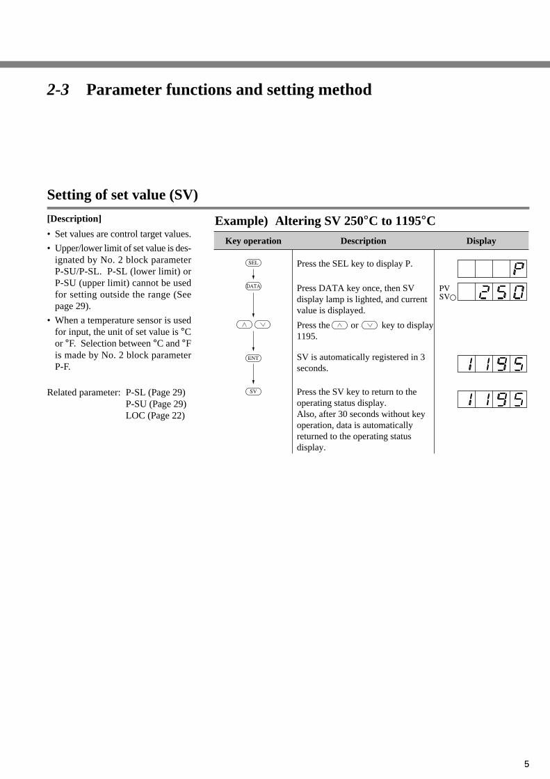
2-3 Parameter functions and setting method
Setting of set value (SV)
[Description]
• Set values are control target values.
• Upper/lower limit of set value is des-ignated by No. 2 block parameterP-SU/P-SL. P-SL (lower limit) orP-SU (upper limit) cannot be usedfor setting outside the range (Seepage 29).
• When a temperature sensor is usedfor input, the unit of set value is °Cor °F. Selection between °C and °Fis made by No. 2 block parameterP-F.
Related parameter: P-SL (Page 29)P-SU (Page 29)LOC (Page 22)
Example) Altering SV 250°C to 1195°C
SEL
ENT
SV
DATA
Key operation Description
Press the SEL key to display P.
Press DATA key once, then SV display lamp is lighted, and current value is displayed.
Press the or key to display1195.
SV is automatically registered in 3seconds.
Press the SV key to return to the operating status display.Also, after 30 seconds without key operation, data is automaticallyreturned to the operating statusdisplay.
Display
PVSV

6
Setting of proportional band (Setting range: 0 to 999.9%
for input range)
[Description]
• Proportional band can be set auto-matically by auto-tuning.
• Manual setting is also possible. IfP value is too small, control actionbecomes unstable, and if it is toolarge, the response becomes slow.
• When P is set to 0.0, 2-position ac-tion becomes effective.
The hysteresis under 2-position ac-tion should be set with the param-eter HYS.
• When dual output type is used andit is set to P = 0.0 and COOL = 0.0,the heating and cooling outputs areas shown in the following diagram.In this case, the hysteresis is fixedat 0.5%.
Related parameter: HYS (Page 12)
Example) Altering proportional band 10.0% to 15.0%
ON ON
Heating output(output 1)
Cooling output (output 2)
OFF OFF PVSVHYS DB
0.5% 0.5%
Key operation Description
Press the SEL key to display P.
Press the DATA key once. Current proportional band (10.0%) is diplayed.
Press the or key to display15.0.
Press the ENT key, then proportionalband is registered.Operation is started with 15.0% pro-portional band.
Hold down the key for 3 seconds todisplay the operation status.
Display
SEL
ENT
SV
DATA

7
Integral time (Setting range: 0 to 3200 sec.)
[Description]
• Integral time can be set automati-cally by auto-tuning.
• Manual setting is also possible.
• When I value is set to 0, integralaction becomes OFF and P actionor PD action is effected.
Example) Altering the integrating time of 600 seconds to
840 secondsKey operation Description
Press the SEL key to display P.
Press the SEL key once.
Press the or key to display840.
Press the DATA key once.Current integrating time (600 seconds) is displayed.
Press the SV key, when you need display the operation status.
Press the ENT key, then the integrat-ing time is registred.Operation is started with an integrat-ing itme of 840 seconds.
Display
SEL
SEL
ENT
SV
DATA

8
Derivative time (Setting range: 0.0 to 999.9 seconds)
[Description]
• Derivative time can be set automati-cally by auto-tuning.
• Manual setting is also possible.
• When D value is set to 0, derivativeaction becomes OFF and P actionor PI action is effected.
Example) Altering a derivative time of 120.0 seconds to
100.0 secondsKey operation Description
Press the SEL key to display P.
Press the SEL key repeatedly until is displayed.
Press the or key to display100.0.
Press the DATA key once.Current derivative time (120.0seconds) is displayed.
Press the SV key when you need todisplay the operation status.
Press the ENT key, then the deriva-tive time is registred.Operation is started with 100.0 seconds of derivative time.
Display
SEL
SEL
ENT
SV
DATA
9
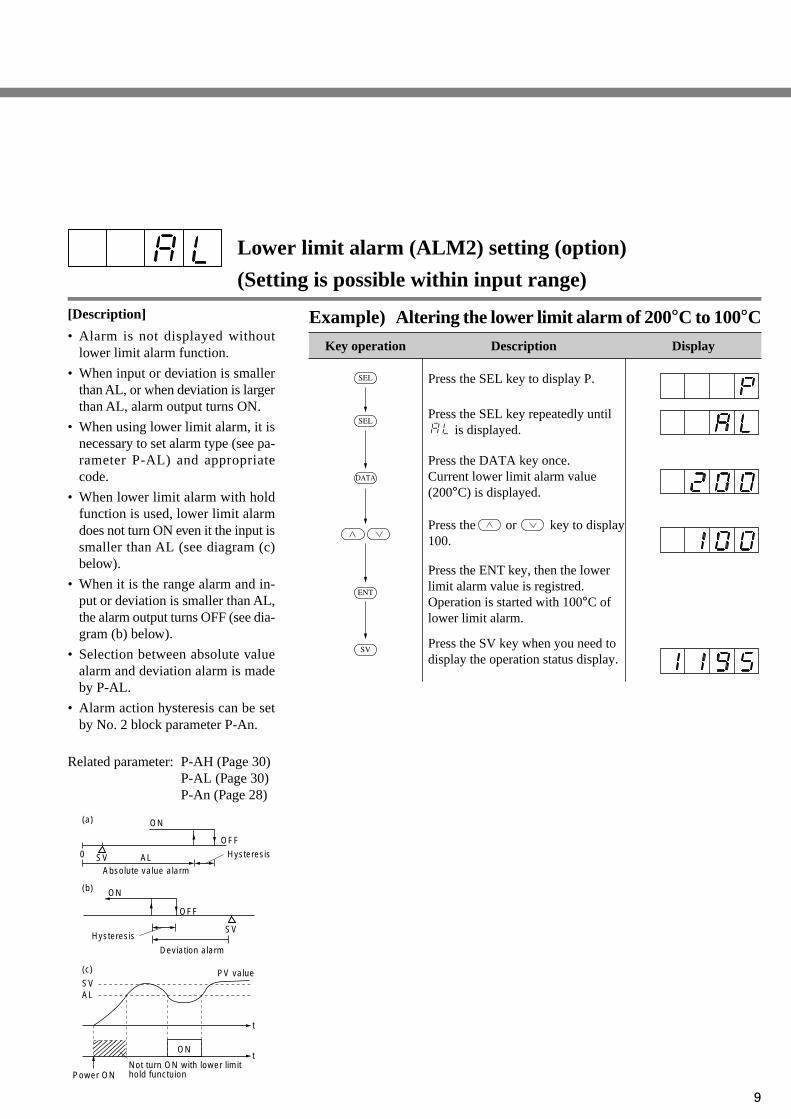
Lower limit alarm (ALM2) setting (option)
(Setting is possible within input range)
[Description]
• Alarm is not displayed withoutlower limit alarm function.
• When input or deviation is smallerthan AL, or when deviation is largerthan AL, alarm output turns ON.
• When using lower limit alarm, it isnecessary to set alarm type (see pa-rameter P-AL) and appropriatecode.
• When lower limit alarm with holdfunction is used, lower limit alarmdoes not turn ON even it the input issmaller than AL (see diagram (c)below).
• When it is the range alarm and in-put or deviation is smaller than AL,the alarm output turns OFF (see dia-gram (b) below).
• Selection between absolute valuealarm and deviation alarm is madeby P-AL.
• Alarm action hysteresis can be setby No. 2 block parameter P-An.
Related parameter: P-AH (Page 30)P-AL (Page 30)P-An (Page 28)
Example) Altering the lower limit alarm of 200°C to 100°C
Key operation Description
Press the SEL key to display P.
Press the SEL key repeatedly until is displayed.
Press the or key to display100.
Press the DATA key once.Current lower limit alarm value(200°C) is displayed.
Press the SV key when you need todisplay the operation status display.
Press the ENT key, then the lowerlimit alarm value is registred.Operation is started with 100°C of lower limit alarm.
Display
SEL
ENT
SV
DATA
SEL
ON
ON
ON
(a)
(b)
(c)
SVPV value
AL
ALAbsolute value alarm
Deviation alarm
SV
SV
0
OFF
Hysteresis
Hysteresis
Power ONNot turn ON with lower limit hold functuion
OFF
t
t

10
[Description]
• Alarm is not displayed without up-per limit alarm function.
• When using upper limit alarm, it isnecessary to set alarm type (see pa-rameter P-AH) and appropriatecode.
• When input or deviation is largerthan AH, the alarm output turns ON(see diagram (a) below).
• When it is the range alarm and in-put or deviation is larger than AH,the alarm output turns ON (see dia-gram (b) below).
• Selection between absolute valuealarm and deviation alarm is madeby P-An.
• Alarm action hysteresis can be setby No. 2 block parameter P-An.
Related parameter: P-AH (Page 30)P-AL (Page 30)P-An (Page 28)
Example) Altering the upper limit alarm of 300°C to
550°CKey operation Description
Press the SEL key to display P.
Press the SEL key repeatedly until is displayed.
Press the or key to display550.
Press the DATA key once.Current upper limit alarm value(300°C) is displayed.
Press the SV key when you need todisplay the operation status display.
Press the ENT key, then the upperlimit alarm value is registred.Operation is started with 550°C of lower limit alarm.
Display
SEL
ENT
SV
DATA
SEL
Upper limit alarm (ALM1) setting (option)
(Setting is possible within input range)
(a)
(b)
SV
SV
0
OFFTemperature
Hysteresis
Temperature
Hysteresis
OFF
ON
AH
Absolute value alarm
Deviation alarm
AH
11
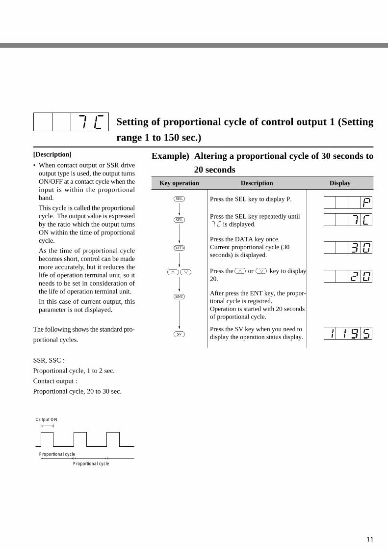
Setting of proportional cycle of control output 1 (Setting
range 1 to 150 sec.)
[Description]
• When contact output or SSR driveoutput type is used, the output turnsON/OFF at a contact cycle when theinput is within the proportionalband.
This cycle is called the proportionalcycle. The output value is expressedby the ratio which the output turnsON within the time of proportionalcycle.
As the time of proportional cyclebecomes short, control can be mademore accurately, but it reduces thelife of operation terminal unit, so itneeds to be set in consideration ofthe life of operation terminal unit.
In this case of current output, thisparameter is not displayed.
The following shows the standard pro-
portional cycles.
SSR, SSC :
Proportional cycle, 1 to 2 sec.
Contact output :
Proportional cycle, 20 to 30 sec.
Example) Altering a proportional cycle of 30 seconds to
20 secondsKey operation Description
Press the SEL key to display P.
Press the SEL key repeatedly until is displayed.
Press the or key to display20.
Press the DATA key once.Current proportional cycle (30seconds) is displayed.
Press the SV key when you need todisplay the operation status display.
After press the ENT key, the propor-tional cycle is registred.Operation is started with 20 seconds of proportional cycle.
Display
SEL
ENT
SV
DATA
SEL
Output ON
Proportional cycle
Proportional cycle
12
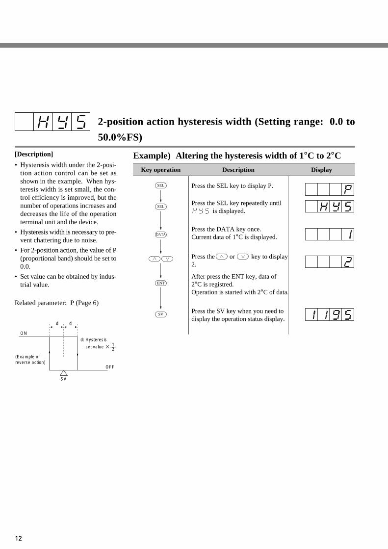
2-position action hysteresis width (Setting range: 0.0 to
50.0%FS)
[Description]
• Hysteresis width under the 2-posi-tion action control can be set asshown in the example. When hys-teresis width is set small, the con-trol efficiency is improved, but thenumber of operations increases anddecreases the life of the operationterminal unit and the device.
• Hysteresis width is necessary to pre-vent chattering due to noise.
• For 2-position action, the value of P(proportional band) should be set to0.0.
• Set value can be obtained by indus-trial value.
Related parameter: P (Page 6)
Example) Altering the hysteresis width of 1°C to 2°C
d d
d: Hysteresis
set value ×
ON
OFF
SV
(Example ofreverse action)
12
Key operation Description
Press the SEL key to display P.
Press the SEL key repeatedly until is displayed.
Press the or key to display2.
Press the DATA key once.Current data of 1°C is displayed.
Press the SV key when you need todisplay the operation status display.
After press the ENT key, data of 2°C is registred.Operation is started with 2°C of data.
Display
SEL
ENT
SV
DATA
SEL

13
Heater burnout alarm (option) (Setting range: 1.0 to 50.0A)
[Description]
• Burnout detect current (parameterHb) should be set according to thetype of heater being used.
It is set to 0.0 prior to delivery fromthe factory.
• Alarm operating point is set by pa-rameter Hb.
• Current detector (CT) comes in 2types, 0 to 30A type (CTL-6-SF) and20 to 50A type (CTL-12-S36-8F).It should be selected according to theheater power source being used.
• Setting of alarm operating point
· Apply current to the heater withthe controller output turned ON.
· Search alarm operating valuewhile changing the set value of Hb(when changing the set value, thenext set value should be changedmore than 3 seconds later).
· After operating point is obtained,use 70 to 80% of the value as thefinal set value.
· When N number of heaters areused, set it in the middle betweenthe current at N number of heat-ers and that of N-1 number.
• The heater burnout alarm functioncan not be used in case when theheater is controlled by thyristorphase angle control system.
• When 3-phase heater is used, heaterburnout can be detected in somecases. For details, contact our of-fice.
• Connect of heater burnout detect CT
• Example of connection of heaterburnout alarm (Type: PXZ5, PXZ9)
Wiring to PXZ (no polarity)
Wiring to heater(through the hole of CT)
• When detection error is large due tosmall heater capacity, increase theapparent current 2 times larger byputting the wire twice through thehole to improve the sensitivity of thedetector (in this case, set the currentto a two-fold value).
• When wire through CT is woundmany turns, be sure to wind it fromthe same direction.
(Note) In using heater burnout alarm,set the proportional cycle (TC)to more than 20 seconds.
Related parameter: TC (Page 11)
1 turn 2 turns
MGSW
Power source100 to 240V AC 50/60Hz
Current detector*CT
Heater
Thermocouple
Magnet switch
Powre source
Control output
Heater burnout alarm output
Electric furnace
⑧
⑨
⑤
⑦
⑮
⑯
⑰ ⑱ ① ② + –
14
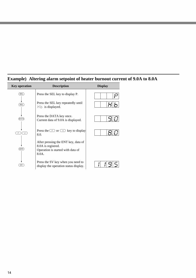
Example) Altering alarm setpoint of heater burnout current of 9.0A to 8.0A
Key operation Description
Press the SEL key to display P.
Press the SEL key repeatedly until is displayed.
Press the or key to display8.0.
Press the DATA key once.Current data of 9.0A is displayed.
Press the SV key when you need todisplay the operation status display.
After pressing the ENT key, data of 8.0A is registred.Operation is started with data of 8.0A.
Display
SEL
ENT
SV
DATA
SEL

15
Auto-tuning (Setting range: 0, 1, 2)
[Description]
• PID value can be set automatically.
• Once PID value is set automaticallyby auto-tuning, it is saved in the con-troller even when the power is turnedOFF, so auto-tuning function is notrequired any further.
• Auto-tuning is started by setting 1or 2 in AT parameter. AT value isautomatically reset to 0 at the endof auto-tuning.
• At the end of auto-tuning, controlaction is started automatically bysetting PID.
• During auto-tuning, the decimalpoint at 1 digit of SV display flick-ers.
• When auto-tuning is forcedly sus-pended, set AT value to 0 or turnOFF the instrument power.
• AT is available in the following 2types.
Example) Starting auto-tuning
Key operation Description
Press the SEL key to display P.
Press the SEL key repeatedly until is displayed.
Press the or key to display1.
Press the DATA key once.Current data of 0 is displayed.
Press the SV key when you need todisplay the operation status display.
Decimal point in 1st digit blinks.
In case of the type of 2-stage display, decimal point in the1st digit of the lower stageblinks.
(In auto-tuning)
When auto-tuning is finished, decimal point is the 1st digit stopsblinking.
(Auto-tuning ends)
Blinking disappears.
After pressing the ENT key, auto-tuning is started automatically.
Display
SEL
ENT
SV
DATA
SEL
• Auto-tuning is available just afterthe start of operation or in the stareof stable control.
Settingcode
1
2
Method
SV typeSV ON-OFF actionLow PV typeSV-10%FS ON-OFF action
During auto-tuning, ON-OFF
control is performed which causes
overshoot for SV. But, the over-
shoot can be eliminated by low PV
type auto-tuning.
Related parameter: P (Page 6)I (Page 7)D (Page 8)
CooL (Page 17)Ar (Page 21)

16
[Description]
• This setting is required only forDUAL type.
• When contact output or SSR driveoutput type is used, the output turnsON/OFF at a constant cycle whenthe input is within the proportionalband.
This cycle is called the proportionalcycle.
The output value is expressed by theratio of which the output turns ONwithin the time of proportionalcycle.
As the time of proportional cyclebecomes short, control can be mademore accurately, but it reduces thelife of operation terminal unit, so itneeds to be set in consideration ofthe life of operation terminal unit.
• In the case of current output, thisparameter is not displayed.
The following shows the standard pro-
portional cycles.
SSR, SSC :
Proportional cycle, 1 to 2 sec.
Contact output :
Proportional cycle, 20 to 30 sec.
Example) Altering cooling control proportional cycle of
30 seconds to 20 secondsKey operation Description
Press the SEL key to display P.
Press the SEL key repeatedly until is displayed.
Press the or key to display20.
Press the DATA key once.Current data (30 seconds) is displayed.
Press the SV key when you need todisplay the operation status display.
After pressing the ENT key, theproportional cycle value of thecontrol output 2 is registered.Operation is started with 20 secondsof cycle.
Display
SEL
ENT
SV
SEL
SEL
Cooling side proportional cycle of control output 2
(DUAL type only) (Setting range: 1 to 150 sec.)
Output ON
Proportional cycle
Proportional cycle

17
Cooling side proportional band coefficient
(DUAL type only) (Setting range: 0, 0.1 to 100.0)
[Description]
• Cooling side proportional band co-efficient can be set automatically byauto-tuning.
• Cooling side proportional band canbe set (see diagram (a) below).
• To set cooling side proportionalband, its coefficient should be ob-tained to optimum control from thefollowing equation after settingheating side proportional band.
· Heating side proportional band is
.
· Set the coefficient to 0, and thecooling side is put in ON-OFFaction.
Example) Altering cooling control proportional band co-
efficient of 5.0 to 5.5Key operation Description
Press the SEL key to display P.
Press the SEL key repeatedly until is displayed.
Press the or key to display5.5.
Press the DATA key once.Current data (5.0 coefficient) is displayed.
Press the SV key when you need todisplay the operation status display.
After pressing the ENT key, the cooling side proportional band coefficient is registered.Operation will be started with 5.5coefficient.
Display
SEL
ENT
SV
DATA
SEL
Output
Setting (SV)
Heating side Cooling side
Coefficient 0.5
Coefficient 1.0
Coefficient 2.0
Deviation (–)
Deviation (+)Heating side
proportional band
Cooling sideproportional
band
Proportional band (P)
(a)
Proportional band (P)2
Example) Set cooling side propor-tional band to 10% of fullscale by proportional band(P) = 50%.
Proportional band (P)2
Cooling side proporitona band =
× Coefficient
Therefore, Coefficient = 0.4
50%2
10% = × Coefficient
Related parameter: P (Page 6)

18
[Description]
• Cooling side proportional band canbe shifted for set value (SV) (seediagram (a) below).
• When the value of db is positive, itis called the dead band, and whenthe value is negative, it is called theoverlap band.
• The value of db is set in MV (%).When it is set in deviation (%), itcan be converted from the follow-ing equation and set.
Example) Altering dead band/overlap band of 0% to 1.0%
(dead band)Key operation Description
Press the SEL key to display P.
Press the SEL key repeatedly until is displayed.
Press the or key to display1.0.
Press the DATA key once.Current data (0%) is displayed.
Press the SV key when you need todisplay the operation status display.
After pressing the ENT key, the shift value of the cooling sideproportional band is registered.Operation will be started with 1.0%.
Display
SEL
ENT
SV
DATA
SEL
Shift of cooling side proportional band
(dead band/overlap band) (DUAL type only)
(Setting range: -50.0 to +50.0%)
(a)Output
Setting (SV)
Heating side Cooling side
Deviation (–)
Deviation (+)
Overlapband
Deadband
Example) When proportional band(P) = 5.0% and dead bandfor SV is set at deviation1.0 (%), the followingequation is used for settingthis parameter to 20%.
Related parameter: P (Page 6)
100P
DB (%) = Deviation × (%)
1005.0
DB (%) = 1.0 × = 20 (%)

19
Output 1 lower limit setting (Setting range: -3.0 to 103.0%)
Output 1 upper limit setting (Setting range: -3.0 to 103.0%)
Output 2 lower limit setting (Setting range: -3.0 to 103.0%)
Output 2 upper limit setting (Setting range: -3.0 to 103.0%)
[Description]
• These setting is not required unlessnecessary especially.
• These are used when the output iscontact output or SSR/SSC driveoutput.
• Output pulse width (ON time) is setnot to lower below the set value(PLC1, PLC2).
Also, output pulse width (ON time)is set not to raise above the set value(PHC1, PHC2). (This determinesthe minimum value of output OFFtime).
• This function prevents flashingwhen combustion is controlled byON/OFF of gas supply.
Example) Altering lower limit pulse width limiter from
20% to 10%Key operation Description
Press the SEL key to display P.
Press the SEL key repeatedly until is displayed.
Press the or key to display10.
Press the DATA key once.Current lower limit pulse widthlimitter (20) is displayed.
Press the SV key when you need todisplay the operation status display.
After pressing the ENT key, the lower limit pulse width limiter is registered.
Display
SEL
ENT
SV
DATA
SEL
Related parameter: TC (Page 11)TC2 (Page 16)
100TC
PLC1 = × (Minimum ON pulse
width [sec.])
PHC1 = 100 – × ( M i n i m u m
OFF pulse width [sec.])
PLC2 = × (Minimum ON pulse
width [sec.])
PHC2 = 100 – × ( M i n i m u m
OFF pulse width [sec.])
TC : Proportional cycle
TC2 : Control output 2 proportionalcycle
100TC
100TC2
100TC2
PHC(TC = 30 sec.)
30 (sec.)
0 Input 100(%)
Out
put
PLC
(No display prior to delivery)

20
[Description]
• This function is used to set the op-eration mode of the output (1 or 2)limiter.
• Normally, this parameter need notbe changed.
• When the output value is set to thelimit set value, it is possible to setwhether the output is limited by thatvalue or it is scaled out.
Example) Set the lower/upper limit of output 1 and out-
put 2 to limit actionKey operation Description
Press the SEL key for 3 seconds,and P-n1 is displayed.
Press the SEL key to display PCUT.
Press the or key to display15.
Press the DATA key to displaycurrent data.
Press the SV key when you need todisplay the operation status display.
After pressing the ENT key, the data is registered.
Display
SEL
ENT
SV
DATA
SEL
Setting of operation mode of output limiter
(Setting range: 0 to 1.5)
103%
Output value
Limit PLC
Scale out
Limit
Scale out
Output value(before limit)
PHC
PLC
PHC
–3%PCUT
0123
4567
89
1011
12131415
103%103%LimitLimit
103%103%LimitLimit
103%103%LimitLimit
103%103%LimitLimit
-3%Limit-3%
Limit
-3%Limit-3%
Limit
-3%Limit-3%
Limit
-3%Limit-3%
Limit
103%103%103%103%
103%103%103%103%
LimitLimitLimitLimit
LimitLimitLimitLimit
-3%-3%-3%-3%
LimitLimitLimitLimit
-3%-3%-3%-3%
LimitLimitLimitLimit
Output 1Upper limit Lower limit Upper limit Lower limit
Output 2

21
Output convergence value (Setting range: -100.0 to 100.0%)
Anti-reset wind up
[Description]
• This setting is not require unless itis necessary.
This function is used to suppressover-shoot.
• Anti-reset wind up (Ar) is automati-cally set in optimum value by P.I.Dauto-tuning.
The value of over-shoot can be con-trolled by setting BAL.
• By setting anti-reset wind up (Ar)in optimum value, unwanted integralaction can be cut and over-shoot isreduces.
(Note) This controller has fuzzy con-trol function, so over-shootcan be minimized without us-ing BAL and Ar. This param-eter is used only for inter-changeability with formertype (PYZ series).
Example) Altering anti-reset wind up of 80°C to 60°C
Key operation Description
Press the SEL key to display P.
Press the SEL key repeatedly until is displayed.
Press the or key to display60.
Press the DATA key once.Current data (80°C) of anti-resetwind up is displayed.
Press the SV key when you need todisplay the operation status display.
After pressing the ENT key, anti-reset wind up data is registred.
Display
SEL
ENT
SV
DATA
SEL
(Setting range: 0 to 100%FS)(No display prior to delivery)
PV
AR value
Integral action is cut in this range.
Integral action is performed in this range.
Integral action is cut in this range.
Time
AR valueSV
22
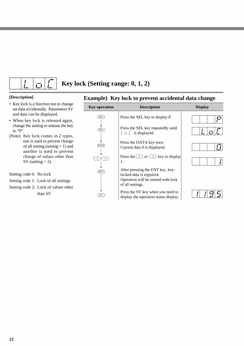
[Description]
• Key lock is a function not to changeset data accidentally. Parameters SVand data can be displayed.
• When key lock is released again,change the setting to release the keyto “0”.
(Note) Key lock comes in 2 types,one is used to prevent changeof all setting (setting = 1) andanother is used to preventchange of values other thanSV (setting = 2).
Setting code 0: No lock
Setting code 1: Lock of all settings
Setting code 2: Lock of values other
than SV
Example) Key lock to prevent accidental data change
Key operation Description
Press the SEL key to display P.
Press the SEL key repeatedly until is displayed.
Press the or key to display1.
Press the DATA key once.Current data 0 is displayed.
Press the SV key when you need todisplay the operation status display.
After pressing the ENT key, key-locked data is registred.Operation will be started with lock of all settings.
Display
SEL
ENT
SV
DATA
SEL
Key lock (Setting range: 0, 1, 2)

23
Program status display (display only)
~ No. 1 to 4 target value
~ No. 1 to 4 ramp time
~ No. 1 to 4 soak time
[Description]
• This is a function to change set value(SV) with time automatically ac-cording to preset pattern. Up to 4ramp/soak data can be programmed.
• No. 1 ramp starts from measurementvalue (PV) just before the programis executed.
• It is also possible to run the programautomatically at power ON (powerON start function).
Example) Set No. 1 target value to 400°C
Key operation Description
Press the SEL key to display P.
Press the SEL key repeatedly untilSV-1 is displayed.
Press the or key to display400°C.
Press the DATA key to display data.
Press the SV key when you need todisplay the operation status display.
After pressing the ENT key, the data is registered.
Display
SEL
ENT
SV
DATA
SEL
Ramp.... Time to change in set value
toward target value.
Soak ..... Time not to change set value
as it is set to target value.
[Parameters]
To execute this function, the program
should be set in advance. It can be set
by setting the required set value (SV)
in the parameters shown in the table
at right.Related parameter: ProG (Page 24)
SV3
Set value
SV2
SV1
SV4PV
TM1R
No.1ramp
TM1S TM2STM2R TM3R TM4R
TM3S
No.1soak
No.2soak
No.3soak
TM4S
Time
No.4soak
No.2 ram
p
No.3 ram
p
No.4 ram
p
Parameterdisplay symbol
Initialvalue atdelivery
Name
STAT
SV-1
SV-4TM1r
TM4rTM1s
TM4sMod
—
0
0.00
0.00
0
Description Remarks
~
~
~
Actual programposition
No.1 to 4 ramptarget value
No.1 to 4 ramptime
No.1 to 4 soaktime
Ramp SV mode
The state of program execution is displayed.This parameter is used only for display and cannot be used for setting.
Not displayed w
hen ramp/soak is not given.
Target value (SV) of each ramp time can beset.(Setting range: 0 to 100%FS)Each ramp time can be set.(Setting range: 0 to 99 hour and 59 minute)
Used for selection of mode of ramp/soakfunction. Normally it is set to “0”.
~
~
~
StopNo.1 to 4 ramp under executionNo.1 to 4 soak under executionProgram end
~ ~

24
Example) Start ramp/soak operation (rUn) from local
operation (oFF)Key operation Description
Press the SEL key to display ProG.
Press the or key to display .
Press the DATA key. Current data( ) is displayed.
Press the SEL key when you need todisplay the operation status display.
After pressing the ENT key, setting data of ramp/soak control is register-ed.Start operation according to presetramp/soak patterns.
Display
SEL
ENT
SEL
DATA
Setting of ramp/soak control (ProG) (option)
[Description]
• This function is used to change timeand set value (SV) automaticallyaccording to preset pattern. Up to 4ramp/soak programs can be used.
• The No. 1 ramp starts from measure-ment value (PV) just before the ex-ecution of program.
• It is also possible to run the programautomatically at power ON (powerON start function).
Ramp.... Range of change in set value
toward target value
Soak ..... Range of unchanged set
value, the same as target
value
SV3
SV2
SV1
SV4PV
TM1R TM1S TM2STM2R TM3R TM4R
TM3S TM4S
Set value
No.1ramp
No.1soak
No.2soak
No.3soak
Time
No.4soak
No.2 ram
p
No.3 ram
p
No.4 ram
p
Related parameter: STAT (Page 23)SV-1~ SV-4 (Page 23)TM1r~ TM4r (Page 23)TM1s~ TM4s (Page 23)

25
Setting of control mode
[Description]
• Used to set control mode, normal/reverse action and the direction ofburnout.
• Control mode is classified into thestandard type (1 output) and the dualoutput type for heating/cooling con-trol.
• The main body of standard type isdifferent from that of dual outputtype. Be sure to set a code that con-forms to the main unit.
Example) Altering lower burnout/reverse action to upper
burnout/normal actionKey operation Description
Press the SEL key for 3 seconds, andP-n1 is displayed.
Press the or key to display3.
Press the DATA key to display data.
Press the SV key when you need todisplay the operation status display.
After pressing the ENT key, upperburnout/normal action is registered.
Display
SEL
ENT
SV
DATA
Code(P-n1)
Outputtype
012
Single ... ...
Reverseaction
Normalaction
Dual
3456789
Reverseaction
Normalaction10
11121314151617
Reverseaction
Normalaction
Reverseaction
Normalaction18
19
Lower limitUpper limitLower limitUpper limitLower limitUpper limitLower limitUpper limitLower limitUpper limitLower limitUpper limit
Upper limit
Lower limitUpper limitLower limitUpper limitLower limitUpper limitLower limitUpper limit
Lower limit
Upper limit
Lower limit
Lower limit
Upper limit
Lower limit
Upper limit
Control actionOutput 1 Output 2 Output 1 Output 2
Direction of burnout
Control action code table

26
Example) Altering filter constant 5.0 (5 seconds) to 10.0
(10 seconds)Key operation Description
Press the SEL key for 3 seconds, andP-n1 is displayed.
Press the SEL key repeatedly untilP-dF is displayed.
Press the or key to display10.0.
Press the DATA key. Current datais displayed.
Press the SV key when you need todisplay the operation status display.
After pressing the ENT key, the data is registered.
Display
SEL
SEL
ENT
SV
DATA
Input filter constant (Setting range: 0.0 to 900.0 sec.)
[Description]
• Input filter function is used to reducenoise contained in input signal. In-put filter constant is time constant.
For example, the following responsecan be obtained by setting the inputfilter constant to 10 seconds.
• The set value is the time to read 63%(Y) on the controller for change inPV of 100% (X).
(Note) The unit is set to 5.0 (5 sec.)prior to delivery. Do notchange it unless necessary.
X YPID
10 sec.
Control outputInputfilter
X,YX
Y
t
10063
(%)

27
Setting of input type
[Description]
• Input type can be set.
• The main unit is determined accord-ing to input type (2 types shownbelow). Set a code that conformswith the main unit.
• Input type can be changed within thesame types. It cannot be changedto different types.
Type I : Thermocouple (9 types),Resistance bulb (1 type)
Type II : Voltage, current
Example) Altering thermocouple from K to T on Type I
Key operation Description
Press the SEL key for 3 seconds, and P-n1 is displayed.
Press the SEL key repeatedly untilP-n2 is displayed.
Press the or key to display7.
“3” is displayed, and it is clear thermocouple K is selected.
Press the SEL key for 3 seconds when you need to display the opera-tion status display.
After pressing the ENT key, the data is registered.
Display
SEL
SEL
ENT
SEL
DATA
• On the Type II, when selecting volt-age input or current input, it becomesnecessary to change the code andconnect an resistor 250Ω to the in-put terminal when current input isused.
• When changing the voltage input,remove the resistor 250Ω from theinput terminal.
• Input type and code
① Input type code table
Change of software
After changing software, turn OFFthe power and then turn ON onceagain.
Type
Resistance bulb
Thermocouple
• Pt100
• J
• K
• R
• B
• S
• T
• E
• N
• PL-II
1
2
3
4
5
6
7
8
12
13
1 to 5V DC, 4 to 20mA DC 16
Code(P-n2)
Related parameter: P-SL (Page 29)P-SU (Page 29)P-dP (Page 33)

28
Example) Altering alarm hysteresis 1°C to 3°C
Key operation Description
Press the SEL key for 3 seconds, and P-n1 is displayed.
Press the SEL key repeatedly untilP-An is displayed.
Press the or key to display3.
Press the DATA key. Current data is displayed.
Press the SV key when you need to display the operation status display.
After pressing the ENT key, the data is registered.
Display
SEL
SEL
ENT
SV
DATA
Alarm hysteresis width (option) (Setting range: 0 to 50%FS)
[Description]
• Alarm is 2-position action, ON andOFF, while hysteresis is the differ-ence in input ON and OFF. For ex-ample, when hysteresis is 5°C, thewidth of ON and OFF is 5°C.
Normally, it is set to 1°C
• Decimal point is given automaticallyby setting it with P-dP.
Related parameter: AL (Page 9)AH (Page 10)P-AH (Page 30)P-AL (Page 30)
ON
ON5°C
5°C
5°C5°C
Input
Input
ON
OFF
OFF
OFF
(Upper limit alarm)
(Lower limit alarm)
(Range alarm)
OFF
AL
AH
AL AH

29
[Description]
• Lower limit (minimum range) andupper limit (maximum range) ofmeasurement ranges can be set.This setting is used as a limiter ofset value (SV). Change of set value(SV) to others outside of the lower/upper limit range is not possible.
• When 1 digit below the decimalpoint needs to be displayed, it shouldbe set to 1 by P-dP.
• When P-n2 is set to 0 to 13 (tem-perature input), up to 1 digit (P-dPparameter = 1) below the decimalpoint becomes effective.
• For the input range, refer to the fol-lowing table.
Related parameter: P-dP (Page 33)
② Input range table (standard range)
Example) Altering the measuring range of 0~ 150°C to
-100~ 200°C (Pt100)Key operation Description
Press the SEL key for 3 seconds, and P-n1 is displayed.
Press the SEL key repeatedly untilP-SL is displayed.
Press the or key to display-100.
Current measuring range is display-ed.
Press the DATA key. Current measuring range is displayed.
Press the SV key when you need to display the operation status display.
After pressing the ENT key, the data is registered.
Press the or key to display200.
After pressing the ENT key, the data is registered.
Display
SEL
SEL
ENT
ENT
SV
DATA
DATA
Pt100Ω
Pt100Ω
Pt100Ω
Pt100Ω
Pt100Ω
Pt100Ω
Pt100Ω
Pt100Ω
Measur-ment range
(°C)
Measur-ment range
(°F)
Withdecimal
point (°C)
Withdecimal
point (°F)
J
J
K
K
K
R
B
S
T
T
E
E
PL-II
Resistancebulb
JIS (IEC)
Thermo-couple
0 to 150
0 to 300
0 to 500
0 to 600
-50 to 100
-100 to 200
-150 to 600
-150 to 850
0 to 400
0 to 800
0 to 400
0 to 800
0 to 1200
0 to 1600
0 to 1800
0 to 1600
-199 to 200
-150 to 400
0 to 800
-199 to 800
0 to 1300
32 to 302
32 to 572
32 to 932
32 to 1112
-58 to 212
-148 to 392
-238 to 1112
-238 to 1562
32 to 752
32 to 1472
32 to 752
32 to 1472
32 to 2192
32 to 2912
32 to 3272
32 to 2912
-328 to 392
-238 to 752
32 to 1472
-328 to 1472
32 to 2372
×
×
×
×
× ×
×
×
×
×
×
×
×
×
× × × × × ×
1 to 5V DCDirectcurrentvoltage
-1999 to 1999
(Scaling possible)
Lower limit of measurement range and set value (SV)
(Setting range: -1999 to 9999)
Upper limit of measurement range and set value (SV)
(Setting range: -1999 to 9999)
* For 4 to 20mA DC input, connect external resistor 250Ω anduse as 1 to 5V DC input.
Note) Input accuracy is ±0.5%FS±1digit with the exception ofthe following.R thermocouple, 0 to 400°C : ±1%FS±1digit±1°CB thermocouple, 0 to 500°C : ±5%FS±1digit±1°COther thermocouples : ±0.5%FS±1digit±1°C
30
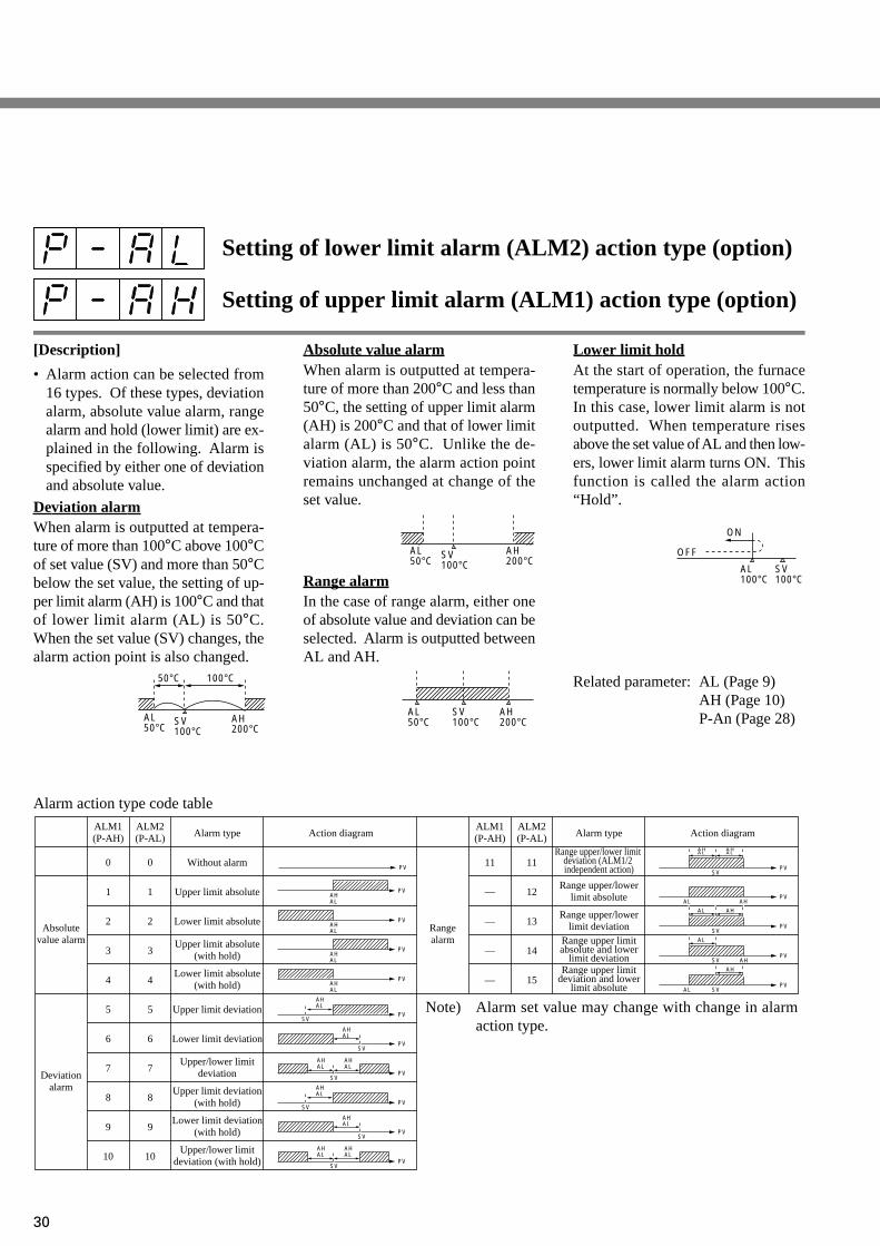
[Description]
• Alarm action can be selected from16 types. Of these types, deviationalarm, absolute value alarm, rangealarm and hold (lower limit) are ex-plained in the following. Alarm isspecified by either one of deviationand absolute value.
Deviation alarmWhen alarm is outputted at tempera-ture of more than 100°C above 100°Cof set value (SV) and more than 50°Cbelow the set value, the setting of up-per limit alarm (AH) is 100°C and thatof lower limit alarm (AL) is 50°C.When the set value (SV) changes, thealarm action point is also changed.
Setting of lower limit alarm (ALM2) action type (option)
Setting of upper limit alarm (ALM1) action type (option)
Absolute value alarmWhen alarm is outputted at tempera-ture of more than 200°C and less than50°C, the setting of upper limit alarm(AH) is 200°C and that of lower limitalarm (AL) is 50°C. Unlike the de-viation alarm, the alarm action pointremains unchanged at change of theset value.
Range alarmIn the case of range alarm, either oneof absolute value and deviation can beselected. Alarm is outputted betweenAL and AH.
Lower limit holdAt the start of operation, the furnacetemperature is normally below 100°C.In this case, lower limit alarm is notoutputted. When temperature risesabove the set value of AL and then low-ers, lower limit alarm turns ON. Thisfunction is called the alarm action“Hold”.
Related parameter: AL (Page 9)AH (Page 10)P-An (Page 28)
ON
OFF
AL100°C
SV100°C
AL50°C
AH200°CSV
100°C
AL50°C
SV100°C
AH200°CAL
50°C
50°C 100°C
SV100°C
AH200°C
Alarm action type code table
PVSV
AHAL
PVSV
AHAL
ALM1(P-AH)
Absolutevalue alarm
Deviationalarm
Upper limit absolute(with hold)
Lower limit absolute(with hold)
Upper limit deviation(with hold)
Upper/lower limitdeviation
Lower limit deviation(with hold)
Upper/lower limitdeviation (with hold)
ALM2(P-AL) Alarm type
Without alarm
Upper limit absolute
Lower limit absolute
Upper limit deviation
Lower limit deviation
0 0
1 1
2 2
3 3
4 4
Rangealarm Range upper limit
absolute and lowerlimit deviation
Range upper limitdeviation and lower
limit absolute
Range upper/lower limit deviation (ALM1/2 independent action)
Range upper/lowerlimit absolute
Range upper/lowerlimit deviation
11 11
— 12
— 13
— 14
— 15
5 5
6 6
7 7
8 8
9 9
10 10
Action diagramALM1(P-AH)
ALM2(P-AL) Alarm type Action diagram
PV
PVAHAL
PVAHAL
PVAHAL
PVAHAL
PVSV
AHAL
PVSV
AHAL
PVSV
AHAL
AHAL
PVSV
AHAL
AHAL
PVSV
AHAL
AHAL
PVAL AH
PVSV
AL AH
PVSV AH
AL
PVSVAL
AH
Note) Alarm set value may change with change in alarmaction type.
31
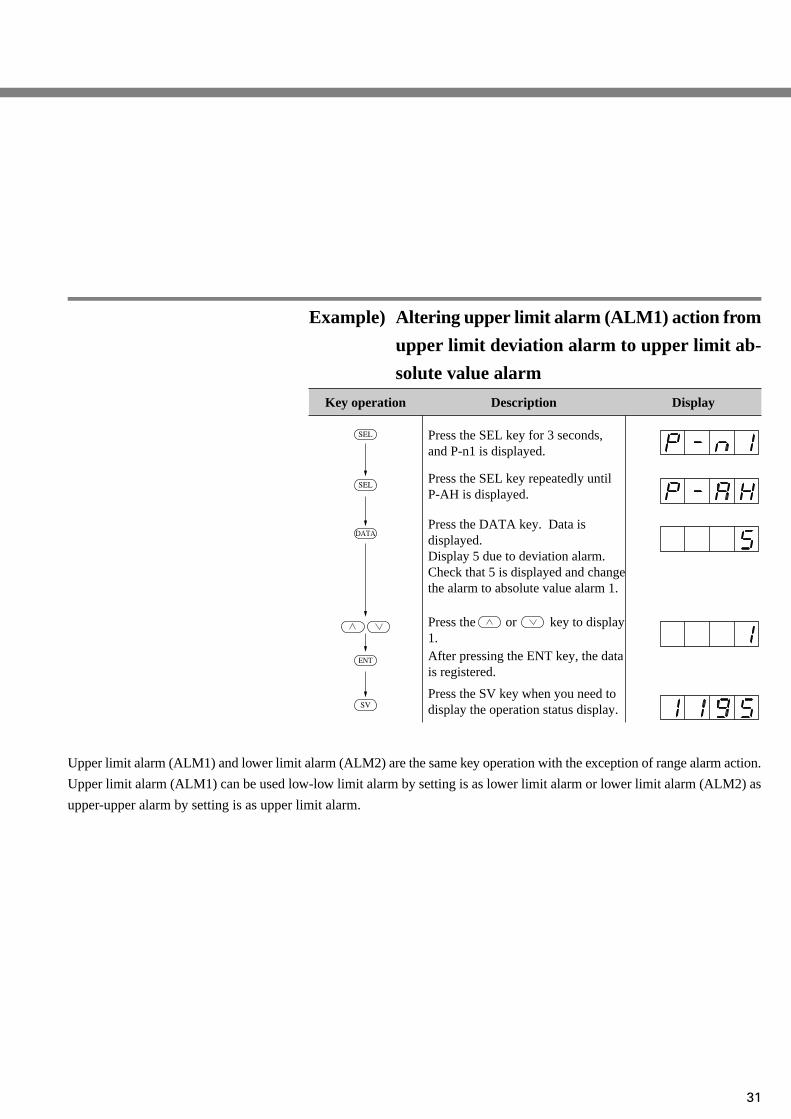
Upper limit alarm (ALM1) and lower limit alarm (ALM2) are the same key operation with the exception of range alarm action.
Upper limit alarm (ALM1) can be used low-low limit alarm by setting is as lower limit alarm or lower limit alarm (ALM2) as
upper-upper alarm by setting is as upper limit alarm.
Example) Altering upper limit alarm (ALM1) action from
upper limit deviation alarm to upper limit ab-
solute value alarm
Key operation Description
Press the SEL key for 3 seconds, and P-n1 is displayed.
Press the SEL key repeatedly untilP-AH is displayed.
Press the or key to display1.
Press the DATA key. Data is displayed.Display 5 due to deviation alarm.Check that 5 is displayed and change the alarm to absolute value alarm 1.
Press the SV key when you need to display the operation status display.
After pressing the ENT key, the data is registered.
Display
SEL
SEL
SV
DATA
ENT
32
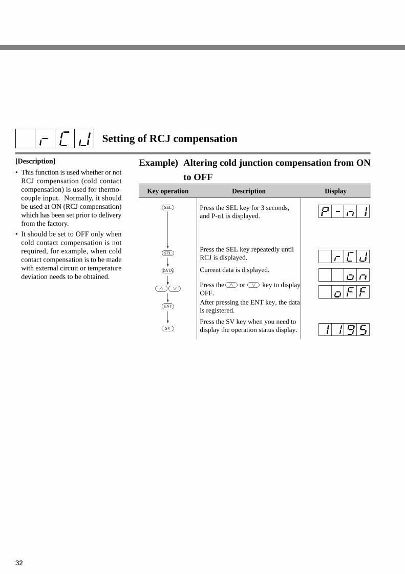
Example) Altering cold junction compensation from ON
to OFFKey operation Description
Press the SEL key for 3 seconds, and P-n1 is displayed.
Press the SEL key repeatedly untilRCJ is displayed.
Press the or key to displayOFF.
Current data is displayed.
Press the SV key when you need to display the operation status display.
After pressing the ENT key, the data is registered.
Display
SEL
SEL
SV
DATA
ENT
Setting of RCJ compensation
[Description]
• This function is used whether or notRCJ compensation (cold contactcompensation) is used for thermo-couple input. Normally, it shouldbe used at ON (RCJ compensation)which has been set prior to deliveryfrom the factory.
• It should be set to OFF only whencold contact compensation is notrequired, for example, when coldcontact compensation is to be madewith external circuit or temperaturedeviation needs to be obtained.

33
Setting of decimal point position (Setting range: 0 to 2)
[Description]
• Decimal point position can be set onLED display.
Example) Altering the measuring range 0~150°C to 0.0
~ 150°CKey operation Description
Press the SEL key for 3 seconds, and P-n1 is displayed.
Press the SEL key repeatedly untilP-dP is displayed.
Press the or key to display1.
“0” is displayed and it is clear thatnone below decimal point is set.
Press the SV key when you need to display the operation status display.
After pressing the ENT key, the data is registered.
Display
SEL
SEL
SV
DATA
ENT
Related parameter: P-SL (Page 29)P-SU (Page 29)
Below decimal point
1 digit below decimal point
2 digit below decimal point
→ “0”
→ “1”
→ “2”

34
Example) Set the zero shift width of 5°C to input value
1200°CKey operation Description
Press the SEL key for 3 seconds, and P-n1 is displayed.
Press the SEL key repeatedly untilPVOF is displayed.
Press the or key to display5.
Press the DATA key. Data isdisplayed.
Press the SV key when you need to display the operation status display.
After pressing the ENT key, the data is registered.
Display
SEL
SEL
SV
DATA
ENT
PV offset (Setting range: -10 to 10%FS)
[Description]
• Set value is added to designated in-put value. It is mainly used whenrecorder needs to conform with thedesignated value.
• Control is performed by the dis-played PV value (PV offset isadded).

35
SV offset (Setting range: -50 to 50%FS)
[Description]
• The value set in SV offset is addedto original SV to perform control bySV value. It is mainly used to elimi-nate offset during P control. In thiscase, designated SV value remainsunchanged.
• Control is performed by the displaySV value (SV offset is added).
Example) Set the zero shift width of 9°C to current set-
ting value.Key operation Description
Press the SEL key for 3 seconds, and P-n1 is displayed.
Press the SEL key repeatedly untilSVOF is displayed.
Press the or key to display9.
Press the DATA key. Data isdisplayed.
Press the SV key when you need to display the operation status display.
After pressing the ENT key, the data is registered.
Display
SEL
SEL
SV
DATA
ENT

36
Example) Altering the unit of measurement input from
°C to °FKey operation Description
Press the SEL key for 3 seconds, and P-n1 is displayed.
Press the SEL key repeatedly untilP-F is displayed.
Press the or key to display°F.
Press the DATA key. Data isdisplayed.
Press the SV key when you need to display the operation status display.
After pressing the ENT key, the data is registered.
Display
SEL
SEL
SV
DATA
ENT
Selection of measurement input °C/°F
[Description]
• The unit (°C or °F) of temperaturecan be selected for temperature in-put. It has been set according to theordering specifications prior to de-livery from factory. If it becomesnecessary to change it after pur-chase, the input range (P-SL, P-SU),alarm value (AL, AH), set value(SV) and offset (PVOF, SVOF)should be changed.The unit of temperature is shown onthe front nameplate. It should alsobe changed at the same time.
Related parameter: SV (Page 5)P-SL (Page 29)P-SU (Page 29)AL (Page 9)AH (Page 10)
95
(Note 1)
T1 (°F) = T2 (°C) + 32

37
FUZY control setting
[Description]
• This function is used to select or notto select FUZY control.
• FUZY control provides the follow-ing advantages.
· Quick start without causing over-shoot
· Quick settlement in response toexternal disturbance.
• Use this function after setting P.I.Dparameter to optimum value, usingauto-tuning, etc.
Example) Set FUZY control to ON.
Key operation Description
Press the SEL key for 3 seconds, and P-n1 is displayed.
Press the SEL key repeatedly untilFUZY is displayed.
Press the or key to displayON.
Press the DATA key. Current data is displayed.
Press the SV key when you need to display the operation status display.
After pressing the ENT key, the data is registered.
Display
SEL
SEL
SV
DATA
ENT

38
[Description]
• This function is used to calibrateinput by user.
• Using zero input or span input, er-ror is set in the input range.
• User calibration function is indepen-dent of adjustment of the controller.By setting 0 in this parameter, it caneasily be set back to the state priorto delivery from the factory.
• It is used to set the same readingbetween controllers or between con-troller and recorder.
Example)
When the input range is 0 to 400°C,the reading at 0°C input is -1°C andthat at 400°C is 402°C.
In this case, when ADJO param-eter is set to 1 and ADJS to -2, thereading at 0°C input becomes 0°Cand that at 400°C input becomes400°C.
When both ADJO and ADJS areset to 0, the controller is set in thecalibrated state prior to deliveryfrom the factory.
Example) Set zero adjustment to +1°C
Key operation Description
Press the SEL key for 3 seconds, and P-n1 is displayed.
Press the SEL key repeatedly untilADJO is displayed.
Press the or key to display1.
Press the DATA key. Current data is displayed.
Press the SV key when you need to display the operation status display.
After pressing the ENT key, the data is registered.
Display
SEL
SEL
SV
DATA
ENT
User’s adjust zero adjustment (Setting range: -50 to 50%FS)
User’s adjust span adjustment (Setting range: -50 to 50%FS)

39
Skipping of parameter display
[Description]
• This parameter is used to skip pa-rameter display for each item.
• This function can be used to preventunused items from being displayedor set values from being changed bymistake.
• Correspondence of the setting ofdSP1 to 7 and skipped items inshown below.
• It is possible to set the total code ofitems to be skipped.
Example) Skip I and D
Set 4 + 8 = 12 according to dSP1 code table.Key operation Description
Press the SEL key for 3 seconds, and P-n1 is displayed.
Press the SEL key repeatedly until is displayed.
Press the or key to display12.
Press the DATA key. Current data is displayed.
Press the SV key when you need to display the operation status display.
After pressing the ENT key, the data is registered.
Display
SEL
SEL
SV
DATA
ENT
(Note 1) Registered function operates normally even when the display is skipped.
No.1block
Parameter DSP allocationPRoG dSP1-1
P dSP1-2I dSP1-4D dSP1-8
AL dSP1-16AH dSP1-32TC dSP1-64
HYS dSP1-128dSP2-1dSP2-2dSP2-4dSP2-8dSP2-16dSP2-32dSP2-64dSP2-128
dSP3-1dSP3-2dSP3-4dSP3-8dSP3-16dSP3-32dSP3-64dSP3-128
dSP4-1dSP4-2dSP4-4dSP4-8dSP4-16dSP4-32dSP4-64dSP4-128
HbATTC2CooL
dbPLC1PHC1PCUTbALAr
LoCSTATSV-1TM1rTM1SSV-2TM2rTM2SSV-3TM3rTM3SSV-4TM4rTM4SMoD dSP5-1
No.2block
P-n1P-n2
dSP5-4dSP5-8
dSP5-16dSP5-32dSP5-64
dSP5-128dSP6-1dSP6-2dSP6-4dSP6-8
dSP6-16dSP6-32dSP6-64
dSP6-128dSP7-1dSP7-2dSP7-4dSP7-8
dSP7-16dSP7-32… …
P-dFP-SLP-SUP-ALP-AHP-AnP-dPRCJ
PVOFSVOF
P-FPLC2PHC2FUZYGAINADJOADJSOUTdSP1dSP2dSP3dSP4dSP5dSP6dSP7
… … … … …

40
3 Troubleshooting
When trouble arises with the unit, check and remove the cause referring to the following table of
troubleshooting.
Trouble
Data are not displayed. (1)(2)(3)
Power is not supplied.Unit is not connected to connector.Instrument is in trouble.
(1)(2)(3)
Check powre source.Connect unit firmly to connector.Replace instrument or contact your dealer for advice.
PV display isor
.
(1)(2)(3)
Measured value is very high or low.Input is not connected.Sensor is damaged.
(1)(2)(3)
Check temperature of controlled object.Connect input terminal.Replace sensor or contact your dealer for advice.
Data are not changed at press of key.
(1)
(2)
Unit is set in the position where parameter cannot be changed.Unit is set over data setting range.
(1)(2)
Check set value of paremater LoC (Page 22).Check set values of parameter P-SL (Page29)and P-SU (Page 29)
HB lamp ON (1) Lamp is ON at detection of heater burnout. (1) Remove the cause of heater burnout.
Control output is not ONwhen output lamp (C1, C2) is ON.
(1)(2)
Output is disconnected.Instrument is in trouble.
(1)(2)
Check connection of output terminal.Replace instrument or contact your dealer for advice.
Hunting of PV (1)(2)(3)
(4)
Input filter time constant is small.Hysteresis is very large for 2-position action.Control output proportional cycle is verylarge.Improper adjustment of PID
(1)(2)(3)
(4)
Check set value of parameter P-dF (Page 26).Check set value of parameter HYS (Page 12).Check set value of parameter TC (Page 11),and TC2 (Page 16) control otuput 2.Perform auto-tuning (Page 15).
Auto-tuning is not finished.
(1)(2)
(3)
Wrong wiringWrong setting of normal/reverse action of controllerTime constant of measured object is very long.
(1)
(2)(3)
Check wiring between control object and controller.Check set value of parameter P-n1 (Page 25).It takes time for time constant. Wait untilit is set.
Cause Remedy

Information in this catalog is subject to change without notice. Printed in Japan
Head OfficeGate City Ohsaki, East Tower, 11-2, Osaki 1-chome,Shinagawa-ku, Tokyo 141-0032, Japanhttp://www.fesys.co.jp/engInstrumentation Div.International Sales Dept.No.1, Fuji-machi, Hino-city, Tokyo, 191-8502 JapanPhone: 81-42-585-6201, 6202 Fax: 81-42-585-6187http://www.fic-net.jp/eng