type design of causeway
DESCRIPTION
Design structure of vented causewayTRANSCRIPT

Name of the work:- B.T.to the Road from DPN Road at 36/2 to Suradavanipeta
Est.Cost:-Rs.529.21 lakhs
Grant:- PMGSY Ph-VI
DESIGN OF LOW LEVEL VENTED CAUSEWAY AT 2/7+50m
DISTRICT : SRIKAKULAM
CIRCLE : SRIKAKULAM
DESIGN OF LOW LEVEL VENTED CAUSEWAY AT 2/7+50m
0 20 40 60 80 100 120 140 160 180 200 220 240 260 280 300 320 340 360 380 400
95.000
95.500
96.000
96.500
97.000
97.500
98.000
98.500
99.000
99.500
100.000
100.500
101.000
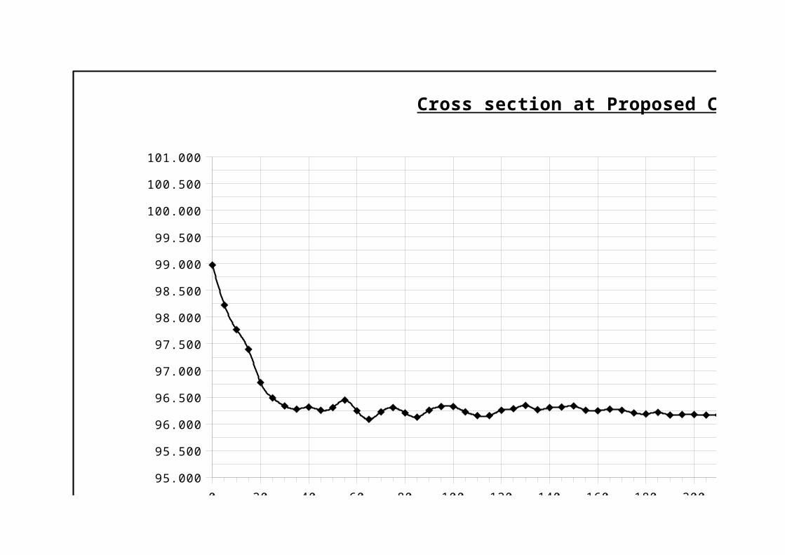
Cross section at Proposed Causeway site
Asst.Exe.Engineer Deputy.Exe.Engineer Exe.EngineerPR,Ichapuram PR,Ichapuram PR,Srikakulam
0 20 40 60 80 100 120 140 160 180 200 220 240 260 280 300 320 340 360 380 400
95.000
95.500
96.000
96.500
97.000
97.500
98.000
98.500
99.000
99.500
100.000
100.500
101.000
Cross section at Proposed Causeway site
0 20 40 60 80 100 120 140 160 180 200 220 240 260 280 300 320 340 360 380 40095.000
95.500
96.000
96.500
97.000
97.500
98.000
98.500
99.000
99.500
100.000
100.500
101.000
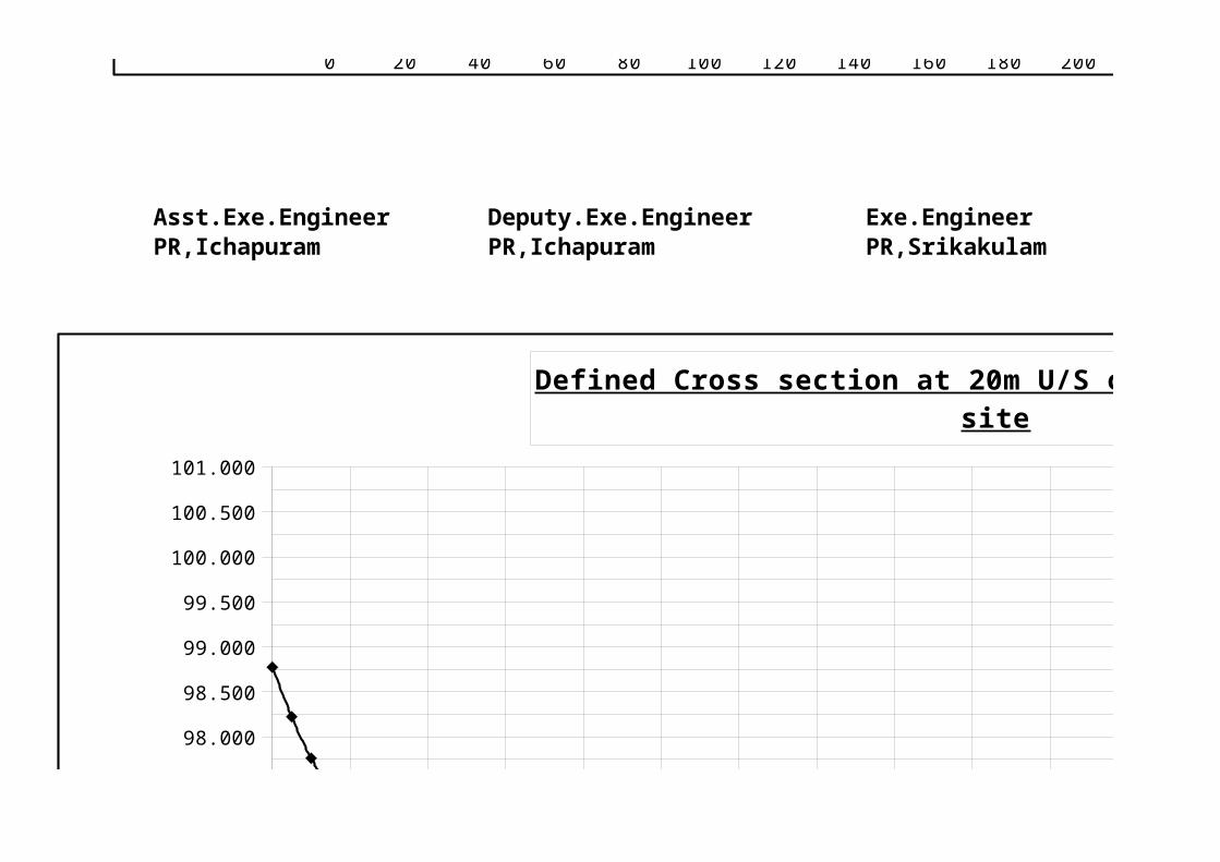
Defined Cross section at 20m U/S of Proposed Causewaysite
Asst.Exe.Engineer Deputy.Exe.Engineer Exe.EngineerPR,Ichapuram PR,Ichapuram PR,Srikakulam
0 20 40 60 80 100 120 140 160 180 200 220 240 260 280 300 320 340 360 380 40095.000
95.500
96.000
96.500
97.000
97.500
98.000
98.500
99.000
99.500
100.000
100.500
101.000
Defined Cross section at 20m U/S of Proposed Causewaysite
0 10 20 30 40 50 60 70 80
93.000
94.000
95.000
96.000
97.000
98.000
99.000
100.000
101.000
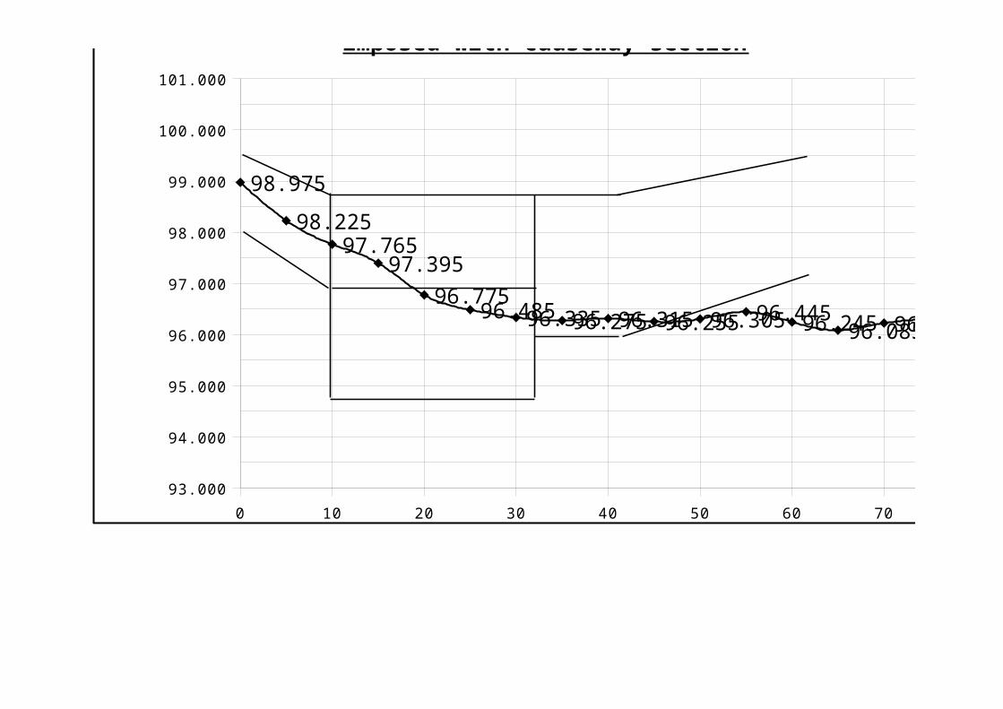
98.975
98.22597.765
97.395
96.77596.48596.33596.27596.31596.25596.30596.44596.24596.08596.22596.305
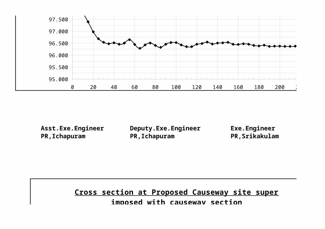
Cross section at Proposed Causeway site super imposed with causeway section
0 10 20 30 40 50 60 70 80
93.000
94.000
95.000
96.000
97.000
98.000
99.000
100.000
101.000
98.975
98.22597.765
97.395
96.77596.48596.33596.27596.31596.25596.30596.44596.24596.08596.22596.305
Cross section at Proposed Causeway site super imposed with causeway section

Asst.Exe.Engineer Deputy.Exe.EngineerPR,Ichapuram PR,Ichapuram
0 10 20 30 40 50 60 70 80
93.000
94.000
95.000
96.000
97.000
98.000
99.000
100.000
101.000
98.975
98.22597.765
97.395
96.77596.48596.33596.27596.31596.25596.30596.44596.24596.08596.22596.305
Cross section at Proposed Causeway site super imposed with causeway section

0 5 10 15 20 25 30
87
87.5
88
88.5
89
89.5
90
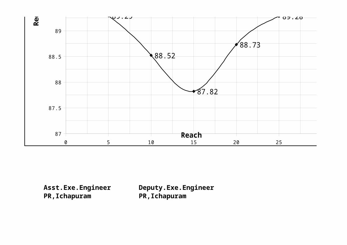
89.86
89.29
88.52
87.82
88.73
89.28
89.73
Cross section at 200m U/S ofProposed Bridge site
Reach
Red
uce
d L
evel
0 10 20 30 40 50 60 70 80
93.000
94.000
95.000
96.000
97.000
98.000
99.000
100.000
101.000
98.975
98.22597.765
97.395
96.77596.48596.33596.27596.31596.25596.30596.44596.24596.08596.22596.305
Cross section at Proposed Causeway site super imposed with causeway section
Asst.Exe.Engineer Deputy.Exe.EngineerPR,Ichapuram PR,Ichapuram
0 5 10 15 20 25 30
87
87.5
88
88.5
89
89.5
90
89.86
89.29
88.52
87.82
88.73
89.28
89.73
Cross section at 200m U/S ofProposed Bridge site
Reach
Red
uce
d L
evel

0 20 40 60 80 100 120 140 160 180 200 220 240 260 280 300 320 340 360 380 400
95.000
95.500
96.000
96.500
97.000
97.500
98.000
98.500
99.000
99.500
100.000
100.500
101.000
Cross section at Proposed Causeway site

0 20 40 60 80 100 120 140 160 180 200 220 240 260 280 300 320 340 360 380 400
95.000
95.500
96.000
96.500
97.000
97.500
98.000
98.500
99.000
99.500
100.000
100.500
101.000
Cross section at Proposed Causeway site
0 20 40 60 80 100 120 140 160 180 200 220 240 260 280 300 320 340 360 380 40095.000
95.500
96.000
96.500
97.000
97.500
98.000
98.500
99.000
99.500
100.000
100.500
101.000
Defined Cross section at 20m U/S of Proposed Causewaysite

0 20 40 60 80 100 120 140 160 180 200 220 240 260 280 300 320 340 360 380 40095.000
95.500
96.000
96.500
97.000
97.500
98.000
98.500
99.000
99.500
100.000
100.500
101.000
Defined Cross section at 20m U/S of Proposed Causewaysite
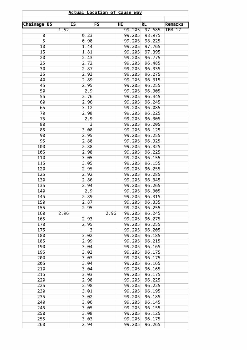
Actual Location of Cause way
Chainage BS IS FS HI RL Remarks1.52 99.205 97.685 TBM 17
0 0.23 99.205 98.9755 0.98 99.205 98.225
10 1.44 99.205 97.76515 1.81 99.205 97.39520 2.43 99.205 96.77525 2.72 99.205 96.48530 2.87 99.205 96.33535 2.93 99.205 96.27540 2.89 99.205 96.31545 2.95 99.205 96.25550 2.9 99.205 96.30555 2.76 99.205 96.44560 2.96 99.205 96.24565 3.12 99.205 96.08570 2.98 99.205 96.22575 2.9 99.205 96.30580 3 99.205 96.20585 3.08 99.205 96.12590 2.95 99.205 96.25595 2.88 99.205 96.325
100 2.88 99.205 96.325105 2.98 99.205 96.225110 3.05 99.205 96.155115 3.05 99.205 96.155120 2.95 99.205 96.255125 2.92 99.205 96.285130 2.86 99.205 96.345135 2.94 99.205 96.265140 2.9 99.205 96.305145 2.89 99.205 96.315150 2.87 99.205 96.335155 2.95 99.205 96.255160 2.96 2.96 99.205 96.245165 2.93 99.205 96.275170 2.95 99.205 96.255175 3 99.205 96.205180 3.02 99.205 96.185185 2.99 99.205 96.215190 3.04 99.205 96.165195 3.03 99.205 96.175200 3.03 99.205 96.175205 3.04 99.205 96.165210 3.04 99.205 96.165215 3.03 99.205 96.175220 2.98 99.205 96.225225 2.98 99.205 96.225230 3.01 99.205 96.195235 3.02 99.205 96.185240 3.06 99.205 96.145245 3.05 99.205 96.155250 3.08 99.205 96.125255 3.03 99.205 96.175260 2.94 99.205 96.265
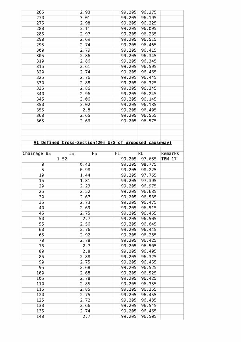
265 2.93 99.205 96.275270 3.01 99.205 96.195275 2.98 99.205 96.225280 3.11 99.205 96.095285 2.97 99.205 96.235290 2.69 99.205 96.515295 2.74 99.205 96.465300 2.79 99.205 96.415305 2.86 99.205 96.345310 2.86 99.205 96.345315 2.61 99.205 96.595320 2.74 99.205 96.465325 2.76 99.205 96.445330 2.88 99.205 96.325335 2.86 99.205 96.345340 2.96 99.205 96.245345 3.06 99.205 96.145350 3.02 99.205 96.185355 2.8 99.205 96.405360 2.65 99.205 96.555365 2.63 99.205 96.575
At Defined Cross-Section(20m U/S of proposed causeway)
Chainage BS IS FS HI RL Remarks1.52 99.205 97.685 TBM 17
0 0.43 99.205 98.7755 0.98 99.205 98.225
10 1.44 99.205 97.76515 1.81 99.205 97.39520 2.23 99.205 96.97525 2.52 99.205 96.68530 2.67 99.205 96.53535 2.73 99.205 96.47540 2.69 99.205 96.51545 2.75 99.205 96.45550 2.7 99.205 96.50555 2.56 99.205 96.64560 2.76 99.205 96.44565 2.92 99.205 96.28570 2.78 99.205 96.42575 2.7 99.205 96.50580 2.8 99.205 96.40585 2.88 99.205 96.32590 2.75 99.205 96.45595 2.68 99.205 96.525
100 2.68 99.205 96.525105 2.78 99.205 96.425110 2.85 99.205 96.355115 2.85 99.205 96.355120 2.75 99.205 96.455125 2.72 99.205 96.485130 2.66 99.205 96.545135 2.74 99.205 96.465140 2.7 99.205 96.505

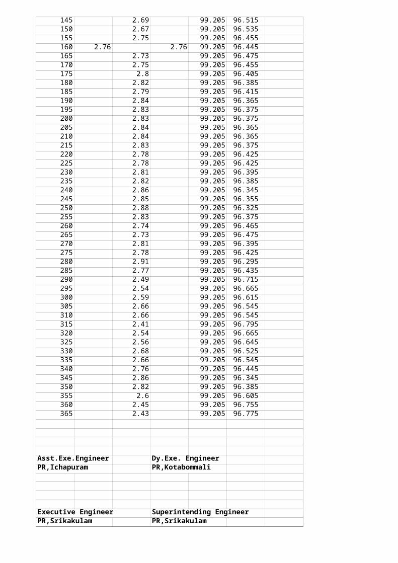
145 2.69 99.205 96.515150 2.67 99.205 96.535155 2.75 99.205 96.455160 2.76 2.76 99.205 96.445165 2.73 99.205 96.475170 2.75 99.205 96.455175 2.8 99.205 96.405180 2.82 99.205 96.385185 2.79 99.205 96.415190 2.84 99.205 96.365195 2.83 99.205 96.375200 2.83 99.205 96.375205 2.84 99.205 96.365210 2.84 99.205 96.365215 2.83 99.205 96.375220 2.78 99.205 96.425225 2.78 99.205 96.425230 2.81 99.205 96.395235 2.82 99.205 96.385240 2.86 99.205 96.345245 2.85 99.205 96.355250 2.88 99.205 96.325255 2.83 99.205 96.375260 2.74 99.205 96.465265 2.73 99.205 96.475270 2.81 99.205 96.395275 2.78 99.205 96.425280 2.91 99.205 96.295285 2.77 99.205 96.435290 2.49 99.205 96.715295 2.54 99.205 96.665300 2.59 99.205 96.615305 2.66 99.205 96.545310 2.66 99.205 96.545315 2.41 99.205 96.795320 2.54 99.205 96.665325 2.56 99.205 96.645330 2.68 99.205 96.525335 2.66 99.205 96.545340 2.76 99.205 96.445345 2.86 99.205 96.345350 2.82 99.205 96.385355 2.6 99.205 96.605360 2.45 99.205 96.755365 2.43 99.205 96.775
Asst.Exe.Engineer Dy.Exe. EngineerPR,Ichapuram PR,Kotabommali
Executive Engineer Superintending EngineerPR,Srikakulam PR,Srikakulam

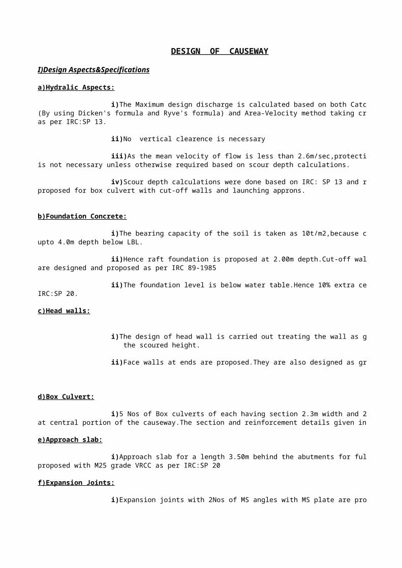
DESIGN OF CAUSEWAY
I)Design Aspects&Specifications
a)Hydralic Aspects:
(By using Dicken's formula and Ryve's formula) and Area-Velocity method taking cross-sections of stream atas per IRC:SP 13.
is not necessary unless otherwise required based on scour depth calculations.
proposed for box culvert with cut-off walls and launching approns.
b)Foundation Concrete:
upto 4.0m depth below LBL.
are designed and proposed as per IRC 89-1985
IRC:SP 20.
c)Head walls:
the scoured height.
d)Box Culvert:
at central portion of the causeway.The section and reinforcement details given in IRC SP-20 are adopted.
e)Approach slab:
proposed with M25 grade VRCC as per IRC:SP 20
f)Expansion Joints:
i)The Maximum design discharge is calculated based on both Catchment area method
ii)No vertical clearence is necessary
iii)As the mean velocity of flow is less than 2.6m/sec,protection of entry and exit ends
iv)Scour depth calculations were done based on IRC: SP 13 and raft foundations are
i)The bearing capacity of the soil is taken as 10t/m2,because clayey soil is met with
ii)Hence raft foundation is proposed at 2.00m depth.Cut-off walls and launching aprons
ii)The foundation level is below water table.Hence 10% extra cement is allowed as per
i)The design of head wall is carried out treating the wall as gravity retaining wall for
ii)Face walls at ends are proposed.They are also designed as gravity retaining walls.
i)5 Nos of Box culverts of each having section 2.3m width and 2.3m height are provided
i)Approach slab for a length 3.50m behind the abutments for full formation width is
i)Expansion joints with 2Nos of MS angles with MS plate are provided.
g)Weep holes&Water spouts:
vertical directions in staggered manner with 1 in 20 slope to the retaining face with 100mm AC pipes of Cl-15.
decking edge.
h)Back filling in between head walls:
75% gravel and 25% sand for full depth for the entire length.
l)Approches:
Assistant Exe.Engineer Dy.Exe. Engineer Executive EngineerPR,Ichapuram PR,Kotabommali PR,Srikakulam
Superintending EngineerPR,Srikakulam
i)In abutments,Weep holes are provided above G.L @ 100mm c/c both horizontal and
ii) GI drainage spouts are provided @ 2 Nos per one deck,each at about 2.65m from the
i)Back filling inn between head walls is provided with granular material consisting of
i)Approaches are proposed with side earth consolidated to OMC.
DESIGN OF VENTED CAUSE WAY
Hydraulic Data:-
Parameter Data Unit
Catchment area(As plotted from Topo sheets) 98.6 Sq.Km
Bed width of defined Cross-Section 305 Metre
Bank width of defined cross-section 365 Metre
HFL 98.885 Metre
LBL(Lowest Bed Level) 96.085 Metre
Discharge by Dicken's Formula 406.77 Cumec
Discharge by Area-Velocity Method 1272.64 Cumec
Protected Bed Level 99.475 Metre
RTL(Road Top Level) 98.335 Metre
Annual Rain fall 1360 mm
1)Area Velocity method:-
At the proposed causeway site:-
Maximum Flood level 98.89mSlope 0.0005Rugosity Coefficient 0.03
S.No Chainage R.L Depth of Average Distance Area Wetted flow depth of (m) (Sqm) perimeter(m) flow (m)
(m)
1 0 98.98 0.09 0.04 0.00 0.00 0.002 5 98.23 0.66 0.38 5.00 1.88 5.053 10 97.77 1.12 0.89 5.00 4.45 5.024 15 97.40 1.49 1.31 5.00 6.53 5.015 20 96.77 2.11 1.80 5.00 9.00 5.046 25 96.49 2.40 2.26 5.00 11.28 5.037 30 96.34 2.55 2.48 5.00 12.38 5.028 35 96.27 2.61 2.58 5.00 12.90 5.019 40 96.32 2.57 2.59 5.00 12.95 5.03
10 45 96.26 2.63 2.60 5.00 13.00 5.0411 50 96.30 2.58 2.61 5.00 13.03 5.0512 55 96.45 2.44 2.51 5.00 12.55 5.0513 60 96.25 2.64 2.54 5.00 12.70 5.0214 65 96.09 2.80 2.72 5.00 13.60 5.0115 70 96.23 2.66 2.73 5.00 13.65 5.0416 75 96.30 2.58 2.62 5.00 13.10 5.0317 80 96.21 2.68 2.63 5.00 13.15 5.0218 85 96.13 2.76 2.72 5.00 13.60 5.0119 90 96.26 2.63 2.70 5.00 13.48 5.0320 95 96.33 2.56 2.60 5.00 12.98 5.0421 100 96.33 2.56 2.56 5.00 12.80 5.0522 105 96.23 2.66 2.61 5.00 13.05 5.0523 110 96.16 2.73 2.70 5.00 13.48 5.02
24 115 96.16 2.73 2.73 5.00 13.65 5.0125 120 96.26 2.63 2.68 5.00 13.40 5.0426 125 96.29 2.60 2.62 5.00 13.08 5.0327 130 96.35 2.54 2.57 5.00 12.85 5.0228 135 96.27 2.62 2.58 5.00 12.90 5.0129 140 96.30 2.58 2.60 5.00 13.00 5.0330 145 96.32 2.57 2.58 5.00 12.88 5.0431 150 96.34 2.55 2.56 5.00 12.80 5.0532 155 96.26 2.63 2.59 5.00 12.95 5.0533 160 96.25 2.64 2.64 5.00 13.18 5.0234 165 96.27 2.61 2.63 5.00 13.13 5.0135 170 96.26 2.63 2.62 5.00 13.10 5.0436 175 96.21 2.68 2.66 5.00 13.28 5.0337 180 96.19 2.70 2.69 5.00 13.45 5.0238 185 96.22 2.67 2.69 5.00 13.43 5.0139 190 96.16 2.72 2.70 5.00 13.48 5.0340 195 96.18 2.71 2.72 5.00 13.58 5.0441 200 96.18 2.71 2.71 5.00 13.55 5.0542 205 96.16 2.72 2.72 5.00 13.58 5.0543 210 96.16 2.72 2.72 5.00 13.60 5.0244 215 96.18 2.71 2.72 5.00 13.58 5.0145 220 96.23 2.66 2.69 5.00 13.43 5.0446 225 96.23 2.66 2.66 5.00 13.30 5.0347 230 96.20 2.69 2.68 5.00 13.38 5.0248 235 96.19 2.70 2.70 5.00 13.48 5.0149 240 96.15 2.74 2.72 5.00 13.60 5.0350 245 96.16 2.73 2.74 5.00 13.68 5.0451 250 96.13 2.76 2.75 5.00 13.73 5.0552 255 96.18 2.71 2.74 5.00 13.68 5.0553 260 96.27 2.62 2.67 5.00 13.33 5.0254 265 96.27 2.61 2.62 5.00 13.08 5.0155 270 96.20 2.69 2.65 5.00 13.25 5.0456 275 96.23 2.66 2.68 5.00 13.38 5.0357 280 96.10 2.79 2.73 5.00 13.63 5.0258 285 96.24 2.65 2.72 5.00 13.60 5.0159 290 96.52 2.37 2.51 5.00 12.55 5.0360 295 96.47 2.42 2.40 5.00 11.98 5.0461 300 96.41 2.47 2.45 5.00 12.23 5.0562 305 96.35 2.54 2.51 5.00 12.53 5.0563 310 96.35 2.54 2.54 5.00 12.70 5.0264 315 96.60 2.29 2.42 5.00 12.08 5.0165 320 96.47 2.42 2.36 5.00 11.78 5.0466 325 96.45 2.44 2.43 5.00 12.15 5.0367 330 96.33 2.56 2.50 5.00 12.50 5.0268 335 96.35 2.54 2.55 5.00 12.75 5.0169 340 96.25 2.64 2.59 5.00 12.95 5.0370 345 96.15 2.74 2.69 5.00 13.45 5.0471 350 96.19 2.70 2.72 5.00 13.60 5.0572 355 96.41 2.48 2.59 5.00 12.95 5.0573 360 96.55 2.33 2.41 5.00 12.03 5.0274 365 96.58 2.31 2.32 5.00 11.60 5.01
922.20 367.18
Hydraulic Radius R= Total area/Wetted perimeter = 2.51
Velocity V = 1.38m/sec1/nX(R2/3XS1/2)
Discharge Q = AXV 1272.64Cumecs
Design of Vents:-
I) Provide vent area 30% of area on defined cross-section of RTL
Bed Widthx(RTL-LBL)x30/100
= 205.88Sqm
ii) a) 2.3m vent rectangular box culverts-----5 Nos Vent Area= 26.45Sqm b) 1000mm dia pipes
No.of pipes required = Vent Area/Area of pipe = 228.36
Say 228Nos
iii) However Provide 70Nos of vents only to accommodate in the bed width
Calculation of area on defined cross-section at RTL--- 98.135m
Chainage GL RTL Length 'm'
0 98.775 99.275 0.50 0.25 0.0 0.0005 98.225 99.085 0.86 0.68 5.0 3.400
10 97.765 98.927 1.16 1.01 5.0 5.05515 97.395 98.795 1.40 1.28 5.0 6.40520 96.975 98.685 1.71 1.56 5.0 7.77525 96.685 98.593 1.91 1.81 5.0 9.04530 96.535 98.517 1.98 1.95 5.0 9.72535 96.475 98.135 1.66 1.82 5.0 9.10540 96.515 98.135 1.62 1.64 5.0 8.20045 96.455 98.135 1.68 1.65 5.0 8.25050 96.505 98.135 1.63 1.65 5.0 8.27555 96.645 98.135 1.49 1.56 5.0 7.80060 96.445 98.135 1.69 1.59 5.0 7.95065 96.285 98.135 1.85 1.77 5.0 8.85070 96.425 98.135 1.71 1.78 5.0 8.90075 96.505 98.135 1.63 1.67 5.0 8.35080 96.405 98.135 1.73 1.68 5.0 8.40085 96.325 98.135 1.81 1.77 5.0 8.85090 96.455 98.135 1.68 1.74 5.0 8.72595 96.525 98.135 1.61 1.64 5.0 8.225
100 96.525 98.135 1.61 1.61 5.0 8.050105 96.425 98.135 1.71 1.66 5.0 8.300110 96.355 98.135 1.78 1.74 5.0 8.725115 96.355 98.135 1.78 1.78 5.0 8.900120 96.455 98.135 1.68 1.73 5.0 8.650125 96.485 98.135 1.65 1.66 5.0 8.325130 96.545 98.135 1.59 1.62 5.0 8.100135 96.465 98.135 1.67 1.63 5.0 8.150140 96.505 98.135 1.63 1.65 5.0 8.250145 96.515 98.135 1.62 1.62 5.0 8.125150 96.535 98.135 1.60 1.61 5.0 8.050155 96.455 98.135 1.68 1.64 5.0 8.200
Difference between RTL&GL 'm'
Mean Difference 'm'
Wetted Area 'Sqm'

160 96.445 98.135 1.69 1.68 5.0 8.425165 96.475 98.135 1.66 1.67 5.0 8.375170 96.455 98.135 1.68 1.67 5.0 8.350175 96.405 98.135 1.73 1.70 5.0 8.525180 96.385 98.135 1.75 1.74 5.0 8.700185 96.415 98.135 1.72 1.73 5.0 8.675190 96.365 98.135 1.77 1.74 5.0 8.725195 96.375 98.135 1.76 1.76 5.0 8.825200 96.375 98.135 1.76 1.76 5.0 8.800205 96.365 98.135 1.77 1.76 5.0 8.825210 96.365 98.135 1.77 1.77 5.0 8.850215 96.375 98.135 1.76 1.76 5.0 8.825220 96.425 98.135 1.71 1.73 5.0 8.675225 96.425 98.135 1.71 1.71 5.0 8.550230 96.395 98.135 1.74 1.72 5.0 8.625235 96.385 98.135 1.75 1.74 5.0 8.725240 96.345 98.135 1.79 1.77 5.0 8.850245 96.355 98.135 1.78 1.78 5.0 8.925250 96.325 98.135 1.81 1.79 5.0 8.975255 96.375 98.135 1.76 1.78 5.0 8.925260 96.465 98.135 1.67 1.71 5.0 8.575265 96.475 98.135 1.66 1.66 5.0 8.325270 96.395 98.135 1.74 1.70 5.0 8.500275 96.425 98.135 1.71 1.72 5.0 8.625280 96.295 98.135 1.84 1.77 5.0 8.875285 96.435 98.135 1.70 1.77 5.0 8.850290 96.715 98.135 1.42 1.56 5.0 7.800295 96.665 98.135 1.47 1.44 5.0 7.225300 96.615 98.135 1.52 1.49 5.0 7.475305 96.545 98.135 1.59 1.55 5.0 7.775310 96.545 98.135 1.59 1.59 5.0 7.950315 96.795 98.135 1.34 1.46 5.0 7.325320 96.665 98.135 1.47 1.40 5.0 7.025325 96.645 98.135 1.49 1.48 5.0 7.400330 96.525 98.135 1.61 1.55 5.0 7.750335 96.545 98.517 1.97 1.79 5.0 8.955340 96.445 98.593 2.15 2.06 5.0 10.300345 96.345 98.685 2.34 2.24 5.0 11.220350 96.385 98.795 2.41 2.38 5.0 11.875355 96.605 98.927 2.32 2.37 5.0 11.830360 96.755 99.085 2.33 2.33 5.0 11.630365 96.775 99.275 2.50 2.41 5.0 12.075
622.620
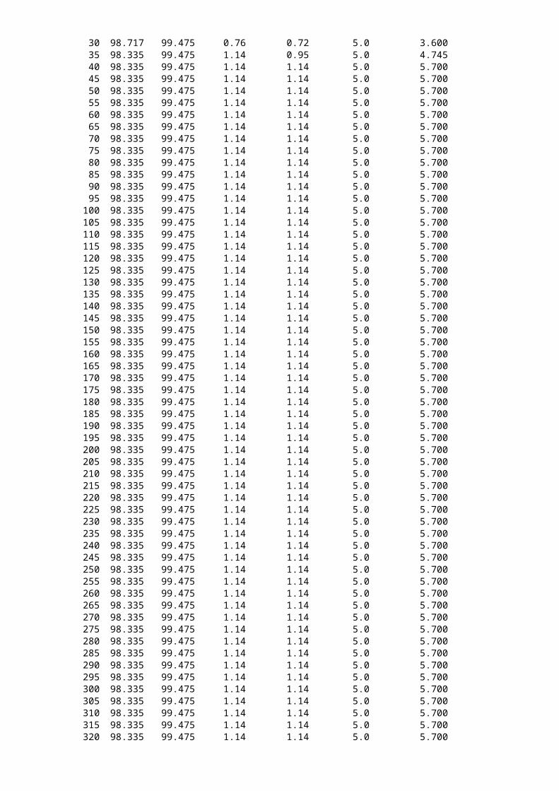
Calculation of area between RTL and PBL on existing cross-section
Chainage RTL PBL Length 'm'
0 99.475 99.475 0.00 0.00 0.0 0.0005 99.285 99.475 0.19 0.09 5.0 0.475
10 99.127 99.475 0.35 0.27 5.0 1.34515 98.995 99.475 0.48 0.41 5.0 2.07020 98.885 99.475 0.59 0.53 5.0 2.67525 98.793 99.475 0.68 0.64 5.0 3.180
Difference between RTL&GL 'm'
Mean Difference 'm'
Wetted Area 'Sqm'

30 98.717 99.475 0.76 0.72 5.0 3.60035 98.335 99.475 1.14 0.95 5.0 4.74540 98.335 99.475 1.14 1.14 5.0 5.70045 98.335 99.475 1.14 1.14 5.0 5.70050 98.335 99.475 1.14 1.14 5.0 5.70055 98.335 99.475 1.14 1.14 5.0 5.70060 98.335 99.475 1.14 1.14 5.0 5.70065 98.335 99.475 1.14 1.14 5.0 5.70070 98.335 99.475 1.14 1.14 5.0 5.70075 98.335 99.475 1.14 1.14 5.0 5.70080 98.335 99.475 1.14 1.14 5.0 5.70085 98.335 99.475 1.14 1.14 5.0 5.70090 98.335 99.475 1.14 1.14 5.0 5.70095 98.335 99.475 1.14 1.14 5.0 5.700
100 98.335 99.475 1.14 1.14 5.0 5.700105 98.335 99.475 1.14 1.14 5.0 5.700110 98.335 99.475 1.14 1.14 5.0 5.700115 98.335 99.475 1.14 1.14 5.0 5.700120 98.335 99.475 1.14 1.14 5.0 5.700125 98.335 99.475 1.14 1.14 5.0 5.700130 98.335 99.475 1.14 1.14 5.0 5.700135 98.335 99.475 1.14 1.14 5.0 5.700140 98.335 99.475 1.14 1.14 5.0 5.700145 98.335 99.475 1.14 1.14 5.0 5.700150 98.335 99.475 1.14 1.14 5.0 5.700155 98.335 99.475 1.14 1.14 5.0 5.700160 98.335 99.475 1.14 1.14 5.0 5.700165 98.335 99.475 1.14 1.14 5.0 5.700170 98.335 99.475 1.14 1.14 5.0 5.700175 98.335 99.475 1.14 1.14 5.0 5.700180 98.335 99.475 1.14 1.14 5.0 5.700185 98.335 99.475 1.14 1.14 5.0 5.700190 98.335 99.475 1.14 1.14 5.0 5.700195 98.335 99.475 1.14 1.14 5.0 5.700200 98.335 99.475 1.14 1.14 5.0 5.700205 98.335 99.475 1.14 1.14 5.0 5.700210 98.335 99.475 1.14 1.14 5.0 5.700215 98.335 99.475 1.14 1.14 5.0 5.700220 98.335 99.475 1.14 1.14 5.0 5.700225 98.335 99.475 1.14 1.14 5.0 5.700230 98.335 99.475 1.14 1.14 5.0 5.700235 98.335 99.475 1.14 1.14 5.0 5.700240 98.335 99.475 1.14 1.14 5.0 5.700245 98.335 99.475 1.14 1.14 5.0 5.700250 98.335 99.475 1.14 1.14 5.0 5.700255 98.335 99.475 1.14 1.14 5.0 5.700260 98.335 99.475 1.14 1.14 5.0 5.700265 98.335 99.475 1.14 1.14 5.0 5.700270 98.335 99.475 1.14 1.14 5.0 5.700275 98.335 99.475 1.14 1.14 5.0 5.700280 98.335 99.475 1.14 1.14 5.0 5.700285 98.335 99.475 1.14 1.14 5.0 5.700290 98.335 99.475 1.14 1.14 5.0 5.700295 98.335 99.475 1.14 1.14 5.0 5.700300 98.335 99.475 1.14 1.14 5.0 5.700305 98.335 99.475 1.14 1.14 5.0 5.700310 98.335 99.475 1.14 1.14 5.0 5.700315 98.335 99.475 1.14 1.14 5.0 5.700320 98.335 99.475 1.14 1.14 5.0 5.700
325 98.335 99.475 1.14 1.14 5.0 5.700330 98.335 99.475 1.14 1.14 5.0 5.700335 98.717 99.475 0.76 0.95 5.0 4.745340 98.793 99.475 0.68 0.72 5.0 3.600345 98.885 99.475 0.59 0.64 5.0 3.180350 98.995 99.475 0.48 0.53 5.0 2.675355 99.127 99.475 0.35 0.41 5.0 2.070360 99.285 99.475 0.19 0.27 5.0 1.345365 99.475 99.475 0.00 0.09 5.0 0.475
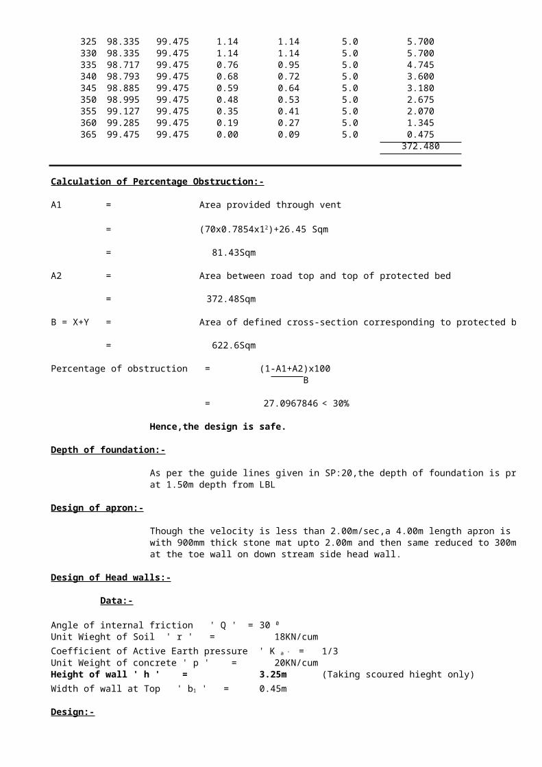
372.480
Calculation of Percentage Obstruction:-
A1 = Area provided through vent
=
= 81.43Sqm
A2 = Area between road top and top of protected bed
= 372.48Sqm
B = X+Y = Area of defined cross-section corresponding to protected bed top
= 622.6Sqm
Percentage of obstruction = (1-A1+A2)x100 B
= 27.09678456 < 30%
Hence,the design is safe.
Depth of foundation:-
As per the guide lines given in SP:20,the depth of foundation is proposed at 1.50m depth from LBL
Design of apron:-
Though the velocity is less than 2.00m/sec,a 4.00m length apron is proposed with 900mm thick stone mat upto 2.00m and then same reduced to 300mmat the toe wall on down stream side head wall.
Design of Head walls:-
Data:-
Angle of internal friction ' Q ' =Unit Wieght of Soil ' r ' = 18KN/cum
1/3Unit Weight of concrete ' p ' = 20KN/cumHeight of wall ' h ' = 3.25m (Taking scoured hieght only)
0.45m
Design:-
(70x0.7854x12)+26.45 Sqm
30 0
Coefficient of Active Earth pressure ' K a ' =
Width of wall at Top ' b1 ' =

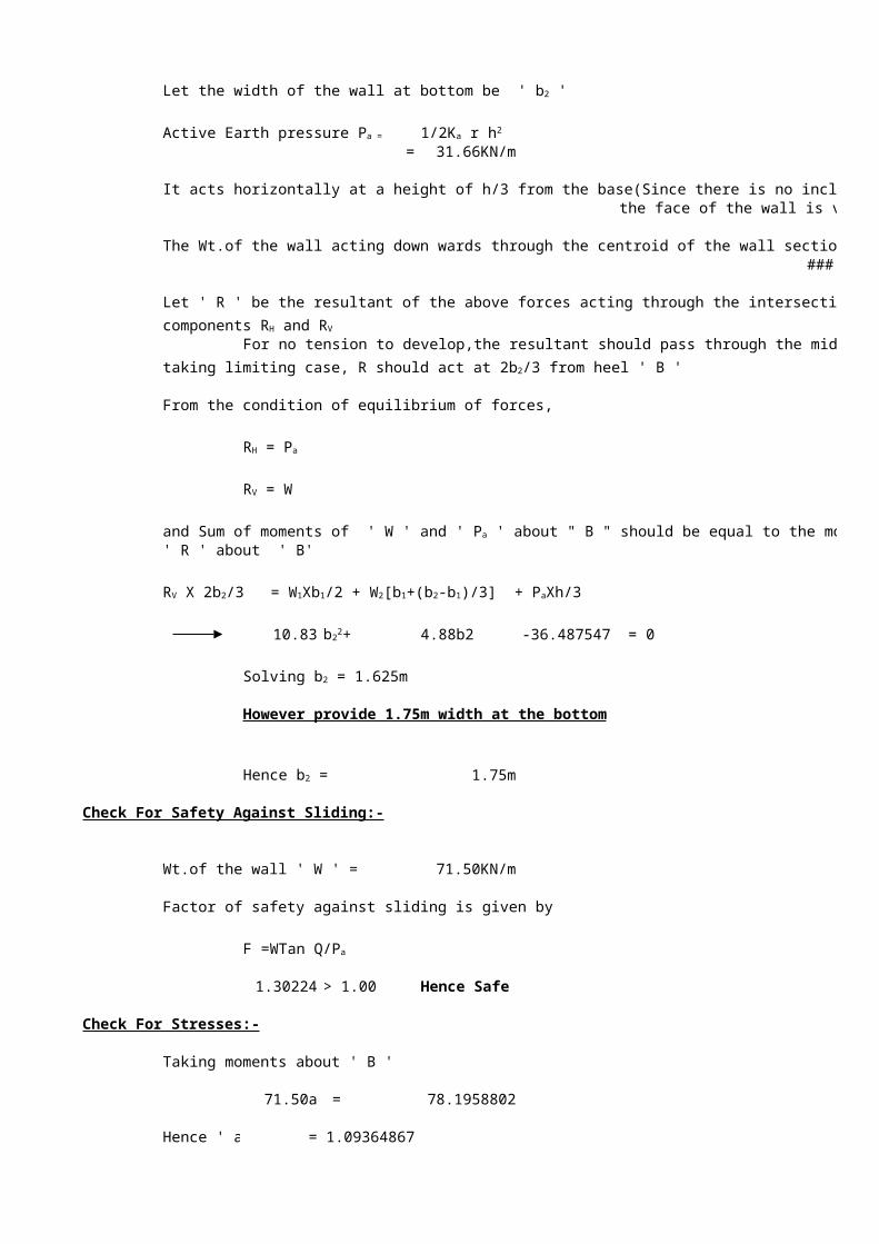
= 31.66KN/m
It acts horizontally at a height of h/3 from the base(Since there is no inclined surcharge and the face of the wall is vertical)
The Wt.of the wall acting down wards through the centroid of the wall section ' W ' = 14.63 +33b2
Let ' R ' be the resultant of the above forces acting through the intersection of the above forces with
For no tension to develop,the resultant should pass through the middle third of the base,
From the condition of equilibrium of forces,
' R ' about ' B'
10.83 4.88b2 -36.4875469 = 0
However provide 1.75m width at the bottom
1.75m
Check For Safety Against Sliding:-
Wt.of the wall ' W ' = 71.50KN/m
Factor of safety against sliding is given by
1.30224 > 1.00 Hence Safe
Check For Stresses:-
Taking moments about ' B '
71.50a = 78.19588021
Hence ' a ' = 1.09364867
Let the width of the wall at bottom be ' b2 '
Active Earth pressure Pa = 1/2Ka r h2
components RH and RV
taking limiting case, R should act at 2b2/3 from heel ' B '
RH = Pa
RV = W
and Sum of moments of ' W ' and ' Pa ' about " B " should be equal to the moment of resultant
RV X 2b2/3 = W1Xb1/2 + W2[b1+(b2-b1)/3] + PaXh/3
b22+
Solving b2 = 1.625m
Hence b2 =
F =WTan Q/Pa
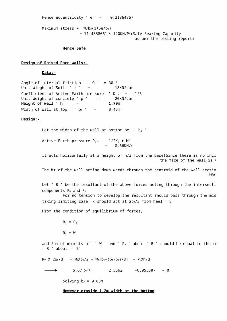
Hence eccentricity ' e ' = 0.218648674
Maximum stress =
= 71.4858061as per the testing report)
Hence Safe
Design of Raised Face walls:-
Data:-
Angle of internal friction ' Q ' =Unit Wieght of Soil ' r ' = 18KN/cum
1/3Unit Weight of concrete ' p ' = 20KN/cumHeight of wall ' h ' = 1.70m
0.45m
Design:-
= 8.66KN/m
It acts horizontally at a height of h/3 from the base(Since there is no inclined surcharge and the face of the wall is vertical)
The Wt.of the wall acting down wards through the centroid of the wall section ' W ' = 7.65 +17b2
Let ' R ' be the resultant of the above forces acting through the intersection of the above forces with
For no tension to develop,the resultant should pass through the middle third of the base,
From the condition of equilibrium of forces,
' R ' about ' B'
5.67 2.55b2 -6.055587 = 0
However provide 1.2m width at the bottom
W/b2(1+6e/b2)
< 120KN/M2(Safe Bearing Capacity
30 0
Coefficient of Active Earth pressure ' K a ' =
Width of wall at Top ' b1 ' =
Let the width of the wall at bottom be ' b2 '
Active Earth pressure Pa = 1/2Ka r h2
components RH and RV
taking limiting case, R should act at 2b2/3 from heel ' B '
RH = Pa
RV = W
and Sum of moments of ' W ' and ' Pa ' about " B " should be equal to the moment of resultant
RV X 2b2/3 = W1Xb1/2 + W2[b1+(b2-b1)/3] + PaXh/3
b22+
Solving b2 = 0.83m
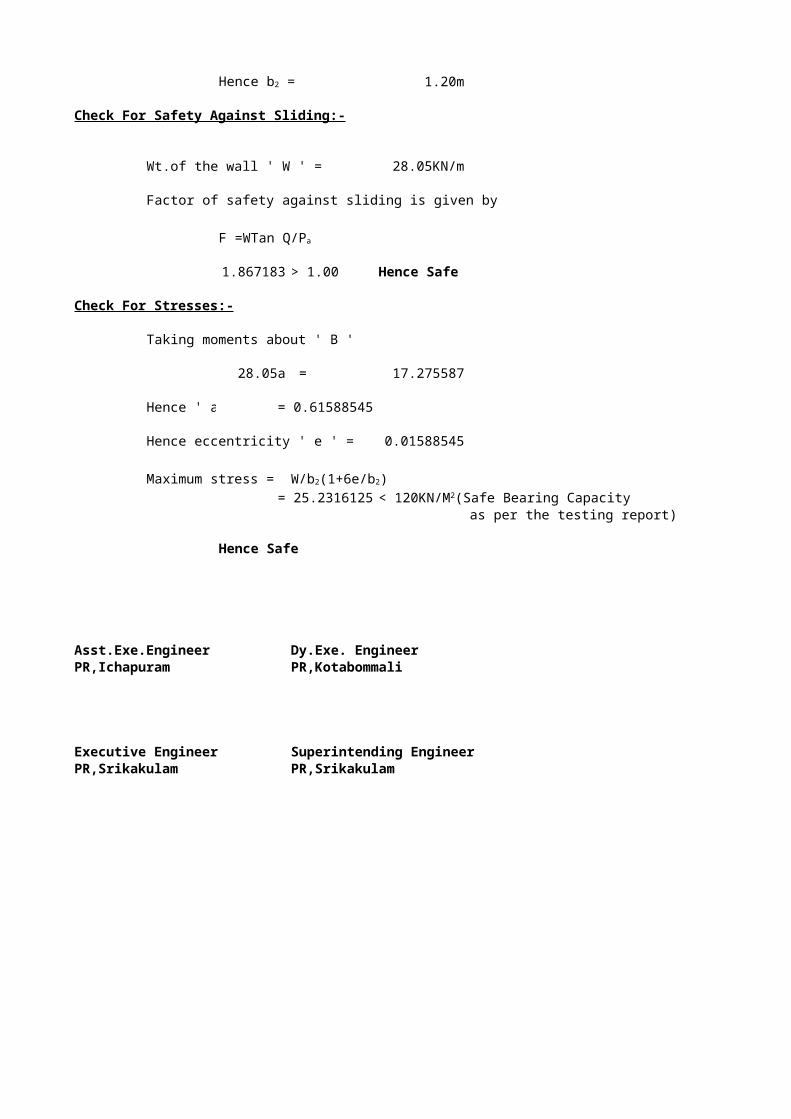
1.20m
Check For Safety Against Sliding:-
Wt.of the wall ' W ' = 28.05KN/m
Factor of safety against sliding is given by
1.867183 > 1.00 Hence Safe
Check For Stresses:-
Taking moments about ' B '
28.05a = 17.275587
Hence ' a ' = 0.61588545
Hence eccentricity ' e ' = 0.015885455
Maximum stress =
= 25.2316125as per the testing report)
Hence Safe
Asst.Exe.Engineer Dy.Exe. EngineerPR,Ichapuram PR,Kotabommali
Executive Engineer Superintending EngineerPR,Srikakulam PR,Srikakulam
Hence b2 =
F =WTan Q/Pa
W/b2(1+6e/b2)
< 120KN/M2(Safe Bearing Capacity
0.04109896
-0.03532033
DESIGN OF CUT-OFF WALLS FOR BOX CULVERT
Name of the work:-B.T to the Road from DPN Road@36/2 to Suradavanipeta
Hydraulic details of CHINNA GEDDA :-
1.Maximum Flood Level 98.89m
2.Ordinary Flood level 97.88m
3.Lowest Bed level 96.09m
4.Average bed slope 0.0005
5.Rugosity Coefficient 0.03
6.Road Crest level 98.335m
7.Bottom of Deck level(For Box culvert only) 98.105m
8.Width of carriage way 5.00m
9.Ryve's Constant 6.80
10.Dicken's Constant 13.00
11.Catchment area of the tank 98.60Sq.Km
Soil Particulars obtained from Trial bores drilled:-
0.00 to 1.00m Sand mixed with Clay
1.00 to 2.00m Sand mixed with Peat
2.00 to 4.00m Sand mixed with silt
4.00 and above Coarse sand
Safe Bearing capacity of the soil(As per the soil testing report enclosed):-
a) At 2.00m depth below LBL:- 11.00--12.00 t/sqm
b) At 4.00m depth below LBL:- 11.00--12.00 t/sqm
Raft of the box culvert is proposed at a depth of 0.30m below LBL.The bearing capacity of soil at thatdepth can be assumed as 11.00t/m2,as the soil is gravel mixed with sand.
A)Discharge Calculations:-
a)From empirical Formulae:-
Maximum flood discharge = Q = =(As per Ryve's formula)
145.35Cumecs
= 406.77Cumecs(As per Duicken's formula)
b)From Area-Velocity method:-
1)Area Velocity method:-
At the proposed causeway site:-
CM2/3. 6.8X(98.6)2/3.
Q = CM3/4
Maximum Flood level 98.89mSlope 0.0005Rugosity Coefficient 0.03
S.No Chainage R.L Depth of Average Distance Area Wetted flow depth of (m) (Sqm) perimeter(m) flow (m)
(m)
1 0 98.98 0.09 0.04 0.00 0.00 0.002 5 98.23 0.66 0.38 5.00 1.88 5.053 10 97.77 1.12 0.89 5.00 4.45 5.024 15 97.40 1.49 1.31 5.00 6.53 5.015 20 96.77 2.11 1.80 5.00 9.00 5.046 25 96.49 2.40 2.26 5.00 11.28 5.037 30 96.34 2.55 2.48 5.00 12.38 5.028 35 96.27 2.61 2.58 5.00 12.90 5.019 40 96.32 2.57 2.59 5.00 12.95 5.03
10 45 96.26 2.63 2.60 5.00 13.00 5.0411 50 96.30 2.58 2.61 5.00 13.03 5.0512 55 96.45 2.44 2.51 5.00 12.55 5.0513 60 96.25 2.64 2.54 5.00 12.70 5.0214 65 96.09 2.80 2.72 5.00 13.60 5.0115 70 96.23 2.66 2.73 5.00 13.65 5.0416 75 96.30 2.58 2.62 5.00 13.10 5.0317 80 96.21 2.68 2.63 5.00 13.15 5.0218 85 96.13 2.76 2.72 5.00 13.60 5.0119 90 96.26 2.63 2.70 5.00 13.48 5.0320 95 96.33 2.56 2.60 5.00 12.98 5.0421 100 96.33 2.56 2.56 5.00 12.80 5.0522 105 96.23 2.66 2.61 5.00 13.05 5.0523 110 96.16 2.73 2.70 5.00 13.48 5.0224 115 96.16 2.73 2.73 5.00 13.65 5.0125 120 96.26 2.63 2.68 5.00 13.40 5.0426 125 96.29 2.60 2.62 5.00 13.08 5.0327 130 96.35 2.54 2.57 5.00 12.85 5.0228 135 96.27 2.62 2.58 5.00 12.90 5.0129 140 96.30 2.58 2.60 5.00 13.00 5.0330 145 96.32 2.57 2.58 5.00 12.88 5.0431 150 96.34 2.55 2.56 5.00 12.80 5.0532 155 96.26 2.63 2.59 5.00 12.95 5.0533 160 96.25 2.64 2.64 5.00 13.18 5.0234 165 96.27 2.61 2.63 5.00 13.13 5.0135 170 96.26 2.63 2.62 5.00 13.10 5.0436 175 96.21 2.68 2.66 5.00 13.28 5.0337 180 96.19 2.70 2.69 5.00 13.45 5.0238 185 96.22 2.67 2.69 5.00 13.43 5.0139 190 96.16 2.72 2.70 5.00 13.48 5.0340 195 96.18 2.71 2.72 5.00 13.58 5.0441 200 96.18 2.71 2.71 5.00 13.55 5.0542 205 96.16 2.72 2.72 5.00 13.58 5.0543 210 96.16 2.72 2.72 5.00 13.60 5.0244 215 96.18 2.71 2.72 5.00 13.58 5.0145 220 96.23 2.66 2.69 5.00 13.43 5.0446 225 96.23 2.66 2.66 5.00 13.30 5.0347 230 96.20 2.69 2.68 5.00 13.38 5.0248 235 96.19 2.70 2.70 5.00 13.48 5.0149 240 96.15 2.74 2.72 5.00 13.60 5.0350 245 96.16 2.73 2.74 5.00 13.68 5.0451 250 96.13 2.76 2.75 5.00 13.73 5.0552 255 96.18 2.71 2.74 5.00 13.68 5.0553 260 96.27 2.62 2.67 5.00 13.33 5.0254 265 96.27 2.61 2.62 5.00 13.08 5.0155 270 96.20 2.69 2.65 5.00 13.25 5.0456 275 96.23 2.66 2.68 5.00 13.38 5.0357 280 96.10 2.79 2.73 5.00 13.63 5.0258 285 96.24 2.65 2.72 5.00 13.60 5.01
59 290 96.52 2.37 2.51 5.00 12.55 5.0360 295 96.47 2.42 2.40 5.00 11.98 5.0461 300 96.41 2.47 2.45 5.00 12.23 5.0562 305 96.35 2.54 2.51 5.00 12.53 5.0563 310 96.35 2.54 2.54 5.00 12.70 5.0264 315 96.60 2.29 2.42 5.00 12.08 5.0165 320 96.47 2.42 2.36 5.00 11.78 5.0466 325 96.45 2.44 2.43 5.00 12.15 5.0367 330 96.33 2.56 2.50 5.00 12.50 5.0268 335 96.35 2.54 2.55 5.00 12.75 5.0169 340 96.25 2.64 2.59 5.00 12.95 5.0370 345 96.15 2.74 2.69 5.00 13.45 5.0471 350 96.19 2.70 2.72 5.00 13.60 5.0572 355 96.41 2.48 2.59 5.00 12.95 5.0573 360 96.55 2.33 2.41 5.00 12.03 5.0274 365 96.58 2.31 2.32 5.00 11.60 5.01
922.20 367.18
Hydraulic Radius R= Total area/Wetted perimeter = 2.51
Velocity V = 1.38m/sec
Discharge Q = AXV 1272.64Cumecs
Scour Depth Calculations:-
Discharge for design of foundations = 1.30XMax.Discharge = 1692.61Cumecs
7
Discharge per metre width of foundations = q = 5.55
2.19m
4.38m
Design of cut-off walls:-
Though,it is sufficient to take the D/S side cut-off upto 1.27 times the normal scour depth as per caluse 703.2.3.2 of IRC 78-1983 considering that the reach is straight,it is proposed take D/S cut off wall uptothe level of Max.scour depth
Max. scour depth from HFL = 4.38m
Depth of bottom of Cut-off wall from HFL = 4.38m
Bottom level of cut-off wall = 94.51
Depth of bottom of D/S side Cut-off wall from LBL 1.58m
Depth of bottom of U/S side Cut-off wall from LBL 1.58m
However provide cut-off wall at 1.50m depth from LBL both for head walls of causeway&for cut-off walls for raft of box culvert
Asst.Executive Engineer Dy.Exe. Engineer Executive EngineerPR(spl),Ichapuram PR,Kotabommali PR,Srikakulam
Superintending Engineer
1/nX(R2/3XS1/2)
Lacey's Silt factor for silty soil = 1.76Xm1/2 =
Normal scour depth D = 1.34(q2/f)1/3 =
Maximum scour depth Dm = 2.0XD =
PR,Srikakulam

0.205 0.01540.6 1.02
0.805 1.03540.4733131.508713
LONGITUDINAL SECTION OF THE BOX CULVERT
RCL-------- 98.335Intermediate wall-0.25m thick Top slab 0.25m thick
2.3m
Bottom of Raft--------- 95.535Abutment---0.25m thick Raft of 0.25m thick
CROSS SECTION OF THE BOX CULVERT
5.0m
Wearing coatHand rails
Top slab
U/S D/S
Toe wallBase concrete--200mm thick Raft slab 0.45
2.0m 2.0m
0.6mGranular filling ----600mm thick
1.5m Apron 600mm to
Cut-off walls 300mm thickApron--900mm thick
Assistant Exe.Engineer Dy.Exe. Engineer Executive Engineer Superintending EngineerPR,Ichapuram PR,Kotabommali PR,Srikakulam PR,Srikakulam
Name of the Work:-Construction of Low Level Causeway at 2/7+50m
PBL--- 99.475
HFL--- 98.885
RTL--- 98.335
Sand filling
LBL--- 96.085
30.0m 305.0m 30.0mBFL--- 94.585
LONGITUDINAL SECTION OF THE CAUSEWAY
NOTE:- 70 Nos of 1000mm dia NP3 pipes&1 No of 5 span 2.3m vent continuous RCC box culvert are proposed.But all the details could not be shown due to limitation of space
U/S D/S5.0m
Guide posts '0.45
C.C(1:2:4)C.C(1:4:8)
1000mm dia NP3 PipeSandFilling(0.30m thick) Granular filling Toe wall
0.45
G.L 2.0m 2.0m
0.6mC.C(1:4:8)
2.00m 0.15m Apron 600mm to
300mm thickApron--900mm thick
2.15m
CROSS SECTION OF PROPOSED CAUSEWAY
Asst.Exe.Engineer Dy.Exe. Engineer Executive Engineer Superintending EngineerPR,Ichapuram PR,Kotabommali PR,Srikakulam PR,Srikakulam