type 1051 and 1052 diaphragm rotary...
TRANSCRIPT
D10
0089
X01
2
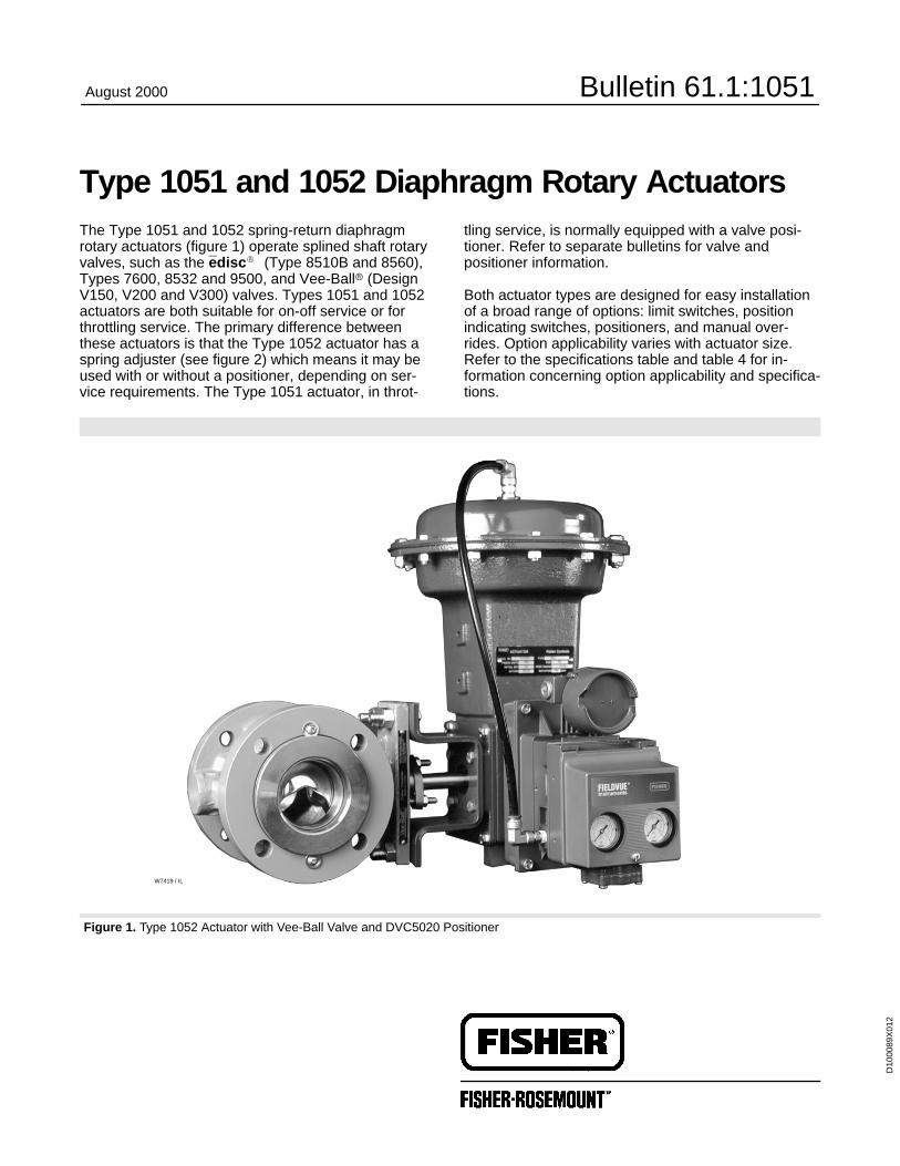
Type 1051 and 1052 Diaphragm Rotary ActuatorsThe Type 1051 and 1052 spring-return diaphragmrotary actuators (figure 1) operate splined shaft rotaryvalves, such as the edisc�
(Type 8510B and 8560),Types 7600, 8532 and 9500, and Vee-Ball� (DesignV150, V200 and V300) valves. Types 1051 and 1052actuators are both suitable for on-off service or forthrottling service. The primary difference betweenthese actuators is that the Type 1052 actuator has aspring adjuster (see figure 2) which means it may beused with or without a positioner, depending on ser-vice requirements. The Type 1051 actuator, in throt-
tling service, is normally equipped with a valve posi-tioner. Refer to separate bulletins for valve andpositioner information.
Both actuator types are designed for easy installationof a broad range of options: limit switches, positionindicating switches, positioners, and manual over-rides. Option applicability varies with actuator size.Refer to the specifications table and table 4 for in-formation concerning option applicability and specifica-tions.
Figure 1. Type 1052 Actuator with Vee-Ball Valve and DVC5020 Positioner
W7419 / IL
August 2000 Bulletin 61.1:1051

Bulletin 61.1:1051
2
Contents
Features 2. . . . . . . . . . . . . . . . . . . . . . . . . . . . . . . . . . .
Options 2. . . . . . . . . . . . . . . . . . . . . . . . . . . . . . . . . . . .
Specifications 3. . . . . . . . . . . . . . . . . . . . . . . . . . . .
Installation 9. . . . . . . . . . . . . . . . . . . . . . . . . . . . . . . . Adjustable Travel Stops 9. . . . . . . . . . . . . . . . . . . . . . . .
TablesDiaphragm Casing Displacement 4. . . . . . . . . . . . . . Construction Materials 4. . . . . . . . . . . . . . . . . . . . . . . . Approximate Actuator Weights 4. . . . . . . . . . . . . . . . . Construction Features and Option
Applicability by Actuator Size 7. . . . . . . . . . . . . . . . Mounting Styles and Positions 8. . . . . . . . . . . . . . . . .
Dimensions 10. . . . . . . . . . . . . . . . . . . . . . . . . . . . . .
Features
� Application Flexibility—Type 1051 and 1052rotary actuators are available with fail-open or fail-closed construction and can be mounted in any of fouractuator-valve mounting positions. See figure 8 formounting positions. These actuators can be mountedon a broad range of Fisher Controls valves (style F orG mounting), or used with other equipment (style H orJ mounting).
� Minimal Dead Band—Single joint linkage withsplined and clamped lever minimizes lost motion andimproves control accuracy.
� Longer Service Life—Rugged construction pro-vides stability, corrosion resistance, and protectionfrom deformation should over-pressurization occur.
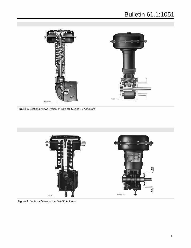
� Safety—Actuator-valve linkage is completely en-closed, yet the valve packing adjustment remains ac-cessible without removing any parts (see figures 3 and4). For safety during disassembly, spring compressionis controlled on the Type 1051 actuator. The Type1052 actuator has an externally accessible spring ad-juster to relieve spring compression (see figure 2).
Options
Top-Mounted Handwheel: For infrequent use as amanual actuator or for use as an adjustable up travelstop (see figure 7). For repeated or daily manual op-
eration, the unit should be equipped with a declutch-able handwheel actuator.
Declutchable Handwheel Actuator: A side-mountedmanual actuator can be used to provide on-site controland to provide override capabilities. Not available forsize 20 actuators. See Bulletin 61.8:1078 for hand-wheel actuator specifications.
Limit Switches: � Micro-Switch or NAMCO switchesfor one or two single-pole, double-throw contacts, or� GO proximity switches for one or two single-pole,double-throw contacts are available (see figure 6).Proximity switches are not available for Type 1052size 70 actuators. See separate bulletins for limitswitch information.
Position Indicating Switch: Type 304 switch for onethrough six single pole, double throw switch contactsare available. See separate bulletin for position indicat-ing switch information.
Positioner: For precise positioning of the valve disk orball, the actuator should be equipped with a positioner.Under some service conditions, the Type 1052 actua-tor may be used successfully in these applicationswithout a positioner. For additional information, contactyour Fisher Controls sales office with complete serviceconditions.
Adjustable Down-Travel Stop: Used to limit the ac-tuator stroke in the downward direction (see figures 5and 6). Not available for size 20 and size 33 actuators.
Adjustable Up-Travel Stop: Used to limit the actuatorstroke in the upward direction (see figures 5 and 6).Though these assemblies may be installed on the size20 and 33 actuators, they are not necessary for stan-dard operation because the size 20 and 33 actuatorshave integral travel stops.
Actuator Locking Mechanism: For size 33 actuators(figure 9) and size 40, 60, and 70 actuators (figure 10),an actuator locking mechanism is available. It can beused to keep the actuator in a locked position (thesame as the spring-fail position) during maintenance.The padlock is not furnished by Fisher Controls, andthe mechanism requires a modified actuator housing.
Pipe Away Vent: Some applications use natural gasor other hazardous gases as a supply pressure to theactuator. These applications sometimes require theactuator housing to be vented reducing the accumula-tion of gases. For new constructions and retrofit kitinformation, contact the sales office with complete ser-vice conditions.

Bulletin 61.1:1051
3
SpecificationsAvailable Configurations
� Type 1051: For on-off service or for throttling� Type 1052: For on-off service without a position-er or for throttling services with or without positionerDirect Acting: Increasing loading pressure extendsthe diaphragm rod out of the spring barrel
Actuator Sizes
Type 1051: � 33, � 40, and � 60Type 1052: � 20, � 33, � 40, � 60, and � 70
Standard Diaphragm Pressure Ranges
Sizes 20 and 60: � 0 to 1.2 bar (0 to 18 psig), � 0to 2.3 bar (0 to 33 psig), and � 0 to 2.8 bar (0 to 40psig)
Sizes 33 and 40: � 0 to 1.2 bar (0 to 18 psig), � 0to 2.3 bar (0 to 33 psig), � 0 to 2.8 bar (0 to 40psig), and � 0 to 3.8 bar (0 to 55 psig)
Size 70: � 0 to 2.3 bar (0 to 33 psig), � 0 to 2.8bar (0 to 40 psig), and � 0 to 3.8 bar (0 to 55 psig)
Maximum Diaphragm Sizing Pressure(1)
Size 20: 3.4 bar (50 psig)Size 33: 3.8 bar (55 psig)Size 40: 4.5 bar (65 psig)Size 60: 2.8 bar (40 psig)Size 70: 3.8 bar (55 psig)
Maximum Diaphragm Casing Pressure
Size 20: 4.1 bar (60 psig)Size 33: 4.5 bar (65 psig)Size 40: 5.2 bar (75 psig)Size 60: 3.4 bar (50 psig)Size 70: 4.5 bar (65 psig)
Nominal Valve Shaft Rotation
� 90 degrees (standard) or � 60 degrees (option-al) for both actuators, or � 75 degrees (optional) forType 1052 actuator only
Valve Shaft Diameters, mm (Inches)
Size 20: 9.5 (3/8), or � 12.7 (1/2)Size 33: � 12.7 (1/2), � 15.9 (5/8), or � 19.1 (3/4)Size 40: � 12.7 (1/2), � 15.9 (5/8), � 19.1 (3/4),� 22.2 (7/8), � 25.4 (1), or � 31.8 (1-1/4)Size 60: � 19.1 (3/4), � 22.2 (7/8), � 25.4 (1), or� 31.8 (1-1/4), � 38.1 (1-1/2), � 44.5 (1-3/4), or
� 50.8 (2)Size 70: � 31.8 (1-1/4), � 38.1 (1-1/2), � 44.5(1-3/4), or � 50.8 (2)
Maximum Breakout Torque
Type 1051
Size 33: Up to 85 N�m (756 lbf�in)Size 40: Up to 322 N�m (2850 lbf�in)Size 60: Up to 626 N�m (5540 lbf�in)
Type 1052
Size 20: Up to 42 N�m (370 lbf�in)Size 33: Up to 132 N�m (1166 lbf�in)Size 40: Up to 371 N�m (3280 lbf�in)Size 60: Up to 730 N�m (6460 lbf�in)Size 70: Up to 1370 N�m (12,100 lbf�in)
Stroking Time
Dependent on actuator size, rotation, spring rate,initial spring compression, supply pressure, and sizeof supply piping. If stroking time is critical, consultyour Fisher Controls sales office
Diaphragm Casing Displacement
See table 1
Construction Materials
See table 3
Material Temperature Capabilities
Nitrile Diaphragm or O-Rings(3): –40 to 82�C (–40to 180�F)
Silicone Diaphragm: –40 to 149�C (–40 to 300�F)
Delrin Push Rods and Guides: –40 to 82�C (–40to 180�F)(4) (Delrin rod & guides are used with le-ver operated switches for size 33 actuators only.)
Travel Indication
Graduated scale and pointer combination locatedon actuator end of valve drive shaft
Pipe or Tubing Connections
Standard: 1/4 inch NPT female
Optional: � 1/2 or � 3/4-inch NPT female, &� 3/4-inch NPT Pipe-Away vent opening
– continued –

Bulletin 61.1:1051
4
Specifications Cont’d.Mounting Positions
See figure 8
Approximate WeightsSee table 2
Options
Option applicability varies with actuator size. Referto table 4 and the following Options section.
1. Use this value to determine the maximum torque output. The pressure/temperature limits in this bulletin and any applicable standard or code limitation for the actuator should not be exceeded.2. Actual actuator torque available depends on specific construction and casing pressure. For information on torque requirements of the valve being considered, contact your Fisher Controlssales office.3. Nitrile O-rings are used in the optional top-mounted handwheel and in the optional up and down travel stop assemblies.4. For higher temperature ratings, contact your Fisher Controls sales office.
Table 1. Diaphragm Casing Displacement
CLEARANCECASING VOLUME(2)
CASINGSIZE
CLEARANCEVOLUME(1) 60 Degree
Rotation90 DegreeRotationSIZE
cm3 Inches3 cm3 Inches3 cm3 Inches3
2033406070
655623
105035403490
403864216213
109818904100
11,60013,929
67115250708850
124523905410
15,20019,025
76146330927
11611. Volume when the diaphragm is in the up position.2. Includes clearance volume.
Table 2. Approximate Actuator Weights
SIZETYPE 1051ACTUATOR
TYPE 1052ACTUATOR
TOP-MOUNTEDHANDWHEELSIZE
Kg Pounds Kg Pounds Kg Pounds
20 - - - - - - 14 30 5.0 11
33 20 45 21 46 5.0 11
40 43 94 45 99 7.3 16
60 89 197 92 203 11 24
70 - - - - - - 123 272 21.3 47
Figure 2. Sectional Views of Spring Seat Construction Details
W4740–1 / ILW4742–1 / IL
������������������ ��������������������������
�����������
������������������ �� ��������������������������
�����������
Table 3. Construction MaterialsPART ACTUATOR MATERIAL
Actuator
Actuator Housing andSpring Barrel(1) All Cast iron
20 Nitrile on nylonDiaphragm
33, 40, 60, & 70 Nitrile on nylon orsilicone on Dacron
Diaphragm Head33, 40, & 60 Aluminum
Diaphragm Head70 Cast Iron
Diaphragm Casing(1) All Pressed steel
Diaphragm Rod All Steel
20 Steel
Housing Cover 33 AluminumHousing Cover40, 60, & 70 Cast iron or aluminum
Lever20 Steel
Lever33, 40, 60, & 70 Ductile iron
Optional Top-Mounted Handwheel Assembly
Handwheel andHandwheel Body
All Cast iron
Handwheel Stem All Bronze
O-Rings All Nitrile
Pusher Plate20, 33, 40, & 60 Steel
Pusher Plate70 Cast iron or steel
Optional Down Travel Stop Assembly
Closing Cap 40, 60 & 70 Brass
O-ring 40, 60 & 70 Nitrile
Stem 40, 60 & 70 Stainless steel
Travel Stop Body 40, 60 & 70 Cast iron
Optional Up Travel Stop Assembly
Closing Cap All Brass
O-Ring All Nitrile
Stem All Bronze
Travel Stop Body All Cast iron1. Housing, lower diaphragm casing, and spring barrel are an integral casing for sizes20 and 33.
Bulletin 61.1:1051
5
Figure 3. Sectional Views Typical of Size 40, 60,and 70 Actuators
W3813-1 / IL
W2291-3 / IL
Figure 4. Sectional Views of the Size 33 Actuator
W4742-1 / ILW4741-1 / IL

Bulletin 61.1:1051
6
Figure 5. Optional Adjustable Travel Stops
�����������������������������������������������������
������������������������������������������
������������������������������������������
�����������������������������������������������������
28A1207-B / DOC
28A1214-B / DOC
CV8057-E / DOC
36A6251-C / DOC

Bulletin 61.1:1051
7
Table 4. Construction Features and Option Applicability by Actuator Size
ACTUATOR ACTUATORSTANDARD TRAVEL STOP OPTIONAL TRAVEL STOP
OPTIONALACCESSORY SWITCH
MOUNTINGACTUATOR
SIZEACTUATOR
TYPEStyle Range of
AdjustabilityStyle Range of
Adjustability
OPTIONALMANUAL
OVERRIDEProximity
(GO)Switches
MechanicallyOperatedSwitches
20 1052
Internallyadjustable
up-travel stop anddown-travel stop
30 degreesup-travel and30 degreesdown-travel Top-mounted
up travel stop
Top-mountedhandwheel
only
Externallymounted, lever
operated
331051 Externally
adjustable35 degrees
up-travel and
up-travel stoponly Top-mounted
hand heel for
Integrallymounted,
Externally331052
adjustableup-travel stop anddown-travel stop
u travel and35 degreesdown-travel 90 degrees
handwheel forinfrequent
operation or
mounted,actuated by
internal cams
Externallymounted, lever
operated
401051
operation orside-mounted
operated
401052 Top-mounted
p tra el stop
side-mountedmanual Externally
mounted lever
601051 Fixed Not applicable
up-travel stopor down-travel
manualactuator for
ro tine
mounted, leveroperated60
1052Fixed Not a licable
or down-travelstop
routineoperation
operated
70 1052sto operation
Not available
Figure 6. Size 33 Actuator with Externally Adjustable Travel Stops and Integrally Mounted, Cam OperatedProximity Switches
PROXIMITYSWITCHES
DOWNTRAVELSTOP
UP TRAVEL STOP
W4738 / IL
Figure 7. Top-Mounted Handwheel
W3145 / IL

Bulletin 61.1:1051
8
( )
BALL VALVE SERIES OR DESIGN DISK VALVE SERIES ORDESIGN
MOUNTING ACTION(1) BALL/PLUGROTATION TO V250 V150 V200 & V300
CV500& DISKROTATION TO
8510B, 8532,8560ROTATION TO
CLOSEV250 V150, V200 & V300
CV500&V500 ROTATION TO
CLOSE8560
& 9500
Right-Hand PDTCPDTO
CCWCCW
AB
AB
AB
CWCW
BA
Left-Hand PDTCPDTO
CCWCCW
CD
CD
CD
CWCW
DC
Left-Hand(Optional)(2, 3)
PDTCPDTO
CWCW
NANA
CD
NANA
NANA
NANA
1. PDTC—Push-down-to-close, and PDTO—Push-down-to-open.2. Applies to Vee-Ball valves only, 3- through 12-inch Series B and 14- to 20-inch, with or without attenuator.3. A left hand ball will be required, consult your Fisher Controls sales office.
Figure 8. Mounting Styles and Positions
1
NOTES:POSITION 1 IS STANDARD; POSITIONS 2 THROUGH 4
(SHOWN IN DOTTED LINES) ARE ALTERNATIVES.1
STYLE D
STYLE C
STYLE B
STYLE A
RIGHT-HANDMOUNTING
43A6505-AA1584-3
STYLE A STYLE B
STYLE D STYLE C
FLOW
FLOW
����������� ������
��������� ������
POSITION 1 POSITION 1
POSITION 1 POSITION 1
4
3
2 4
3
2
4
3
2 4
3
2LEFT-HANDMOUNTING
1
11

Bulletin 61.1:1051
9
Figure 9. Actuator Locking Mechanism for Size 33
24B0391-AA6226 / IL
PADLOCK(CUSTOMER SUPPLIED)
CAP SCREW GROOVE PIN
MOUNTING PLATECAP SCREW
COVER
MOUNTING PLATE ASSY
Installation
The actuator is normally positioned vertically in a hori-zontal pipeline. Four mounting styles and four posi-tions for each style are possible (see figure 8). Due toits weight, the Type 1052 size 70 actuator must be ex-ternally supported if mounted in the horizontal position.
When looking in the direction of flow in the pipeline, anactuator is right-hand mounted when it is on the rightside of the pipeline, and an actuator is left-handmounted when it is mounted on the left side of thepipeline.
By Fisher Controls definition, forward flow is into theface side of the disk or ball, and reverse flow is into thehub side of the disk or ball.
Dimensions for both actuator types are shown in figure11. These dimensions should be used in conjunction
Figure 10. Actuator Locking Mechanism forSizes 40, 60, and 70
A6019-2 / IL
ACTUATORLEVER
MODIFIEDACTUATORHOUSING
PADLOCK(CUSTOMERSUPPLIED)
LOCKINGMECHANISM
with the mounting positions shown in figure 8. Makeclearance considerations before mounting the actuatorto determine the most suitable mounting position.
Adjustable Travel Stops
Adjustable travel stops (in addition to those shown infigure 5) are available as discussed below.
As used here, down or downward means in a directiontoward the valve shaft and away from the piston anddiaphragm.
An adjustable down travel stop for Type 1051 (size 40and 60) and Type 1052 (size 30, 40, 60, and 70) isinstalled in a special actuator housing. The assemblyconsists of a special housing, cap screw, locknut, le-ver, and rod end bearing. The cap screw can be posi-tioned to limit downward travel of the actuator lever toany rotation between 0 and 90 degrees.
The locking mechanism shown in figures 9 and 10 isnot to be used as a travel stop. Please specify an ad-justable travel stop assembly instead.

Figure 11. Dimensions
REFERENCE A
14A7222-FA2206-4 / IL
�������!��������� ��������� ������
REFERENCE B
W DIA
W DIA
T
T
U
14A7222-F16A0600-BB1412-4 / IL
����� �����������"���"���"��������������
C DIA
P
F Y
V
H
E
H
1/2-14 NPTSIZE 70 1/4-18 NPT
SIZE 20, 40,& 60
����� �� ����� ���������##�����������
����� �� ����������������������
C DIA
P
F Y
V
H
E
1/4-18 NPT
Bulletin 61.1:1051
10
ACTUATOR CE
F H P YACTUATORSIZE
CType 1051 Type 1052
F H P YSIZE
mm Inches mm Inches mm Inches mm Inches mm Inches mm Inches mm Inches
20 251 9.88 - - - - - - 256 10.06 18 0.69 76 3.00 52 2.06 59 2.32
33 289 11.38 338 13.31 338 13.31 33 1.31 116 4.56 92 3.62 65 2.56
40 333 13.12 505 19.88 607 23.88 54 2.12 114 4.50 175 6.88 73 2.88
60 473 18.62 749 29.50 876 34.50 64 2.50 121 4.75 186 7.31 76 3.00
70 536 21.12 - - - - - - 849 33.44 64 2.50 121 4.75 186 7.31 76 3.00
VALVE SHAFTDIAMETER FIGURE
REFERENCE
T U V W
mm InchesREFERENCE
mm Inches mm Inches mm Inches mm Inches
Style F Mounting: Vee-Ball, 8532 and 8510B & 8560 edisc Valves
12.7 - 15.9 1/2 - 5/8 A 117 4.62 - - - - - - 137 5.38 14.2 0.56
19.1 - 25.4 3/4 - 1 B 152 6.00 32 1.25 160 6.31 14.2 0.56
31.8 - 38.1 1-1/4 - 1 -1/2 B 235 9.25 46 1.81 148 5.81 17.5 0.69
44.5 - 50.8 1-3/4 - 2 B 273 10.75 51 2.00 286 11.25 20.6 0.81
Style G Mounting: 7600 and 9500 Series Valves
12.7 1/2 A 117 4.62 - - - - - - 137 5.38 11.0 0.44
15.9 - 25.4 5/8 - 1 B 146 5.75 32 1.25 160 6.31 11.0 0.44
31.8 - 38.1 1-1/4 - 1-1/2 B 210 8.25 51 2.00 148 5.81 17.5 0.69
44.5 - 50.8 1-3/4 - 2 B 241 9.50 70 2.75 286 11.25 20.6 0.81
Bulletin 61.1:1051
11
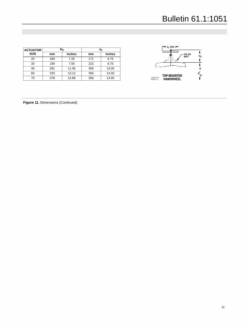
ACTUATOR HC JCACTUATORSIZE mm Inches mm Inches
20 184 7.25 171 6.75
33 190 7.50 222 8.75
40 281 11.06 356 14.00
60 333 13.12 356 14.00
70 378 14.88 356 14.00
Figure 11. Dimensions (Continued)
JC DIA
HC
E
��� ��������������
14A7221-DA3023 / IL
1/4-18NPT

Bulletin 61.1:1051
12
For information, contact Fisher Controls:Marshalltown, Iowa 50158 USACernay 68700 France Sao Paulo 05424 BrazilSingapore 128461
������������������� ���������������������������������������� �������������������������������������������������� ������������ ������������������������������ ������������������� ��������������
������������������������������ �������������������������������������� ��������������������������������������������������������������������������������������� ������� �������������������� ���������
Printed in U.S.A.
�Fisher Controls International, Inc. 1983, 2000; All Rights Reserved
edisc, Vee-Ball, Fisher and Fisher-Rosemount are marks owned by Fisher Controls International, Inc. or Fisher-Rosemount Systems, Inc.All other marks are the property of their respective owners. This product may be covered by one or more of the following patents: 4,746,772 or under pending patents.