tx3-bbcx-4w assembly - mircom · documentation is subject to change without notice. see for the...
TRANSCRIPT

Documentation is subject to change without notice. See http://www.mircom.com/tx3 for the latest version of this document.Mircom technical support: 1-888-647-2665
TX3-BBCX-4W Assembly
Lower battery shelf
Upper battery shelf
Standoffs (x8)
Card Access Controller (MD-1093)
P7 LED display port
Screws (x8)
MOUNT AND WIRE THE CARD ACCESS CONTROLLERS (CONTROL BOARDS)
• Mount each control board so that the mounting posts align and the P7 LED display port is on the left. (The orientation of the boards is not the same as in the single board cabinet.)
• Mount up to 4 control boards in the enclosure.
• Mount the control boards in two layers using the standoff s.
Figure 1: DIP Switch settings for RS-485
DIP SWITCH (SW2) SETTINGS FOR RS-485
Each card must have a unique RS-485 address.Use DIP switches 1-6 to set the RS-485 network address. See LT-980 for details.Set DIP switch 8 off to get an IP address from the DCHP server.Set DIP switch 8 on to get an IP address from the TX3 Confi gurator software.
Address 1ON
OFF
Address 4Address 2 Address 3
1 8 1 8 1 8 1 8
• After you mount each control board, connect the RS-485 wires and other inputs and outputs as described on pages 2 and 3.
• After you mount each control board, connect the LED ribbon cable to the P7 LED display port.
1
2
© Mircom 2015Printed in Canada
Subject to change without prior noticeLT-1182 rev 1.2 Page 1 of 6
A complete library of product information is available at: www.mircom.com/tx3
Figure 2: Mounting the card access controllers
Qty 8... #6-32 screwsQty 8... Standoff sQty 1... USB cableQty 1... USB diskQty 8... Battery cablesQty 1... 14 AWG Grounding wireQty 1... #8 x 1/4” ground screw
CONTENTS OF THE KIT
Mircom25 Interchange Way Vaughan (Toronto), Ontario L4K 5W3CanadaTechnical Support: 888-647-2665General Inquiries: 1-888-660-4655
US Address::4575 Witmer Industrial EstatesNiagara FallsNY 14305

Documentation is subject to change without notice. See http://www.mircom.com/tx3 for the latest version of this document.Mircom technical support: 1-888-647-2665
Warning: Turn the power off before wiring.
Before you beginUnless specifi ed otherwise, all wiring is a maximum length of 1000 ft (304.8 m).The RS-485 wiring maximum length is 4000 ft (1219.2 m).
Note: In the TX3-BBCX-4W, the board is rotated so that thefront door LED connector on the left. Make allowances for allconfi gurable features such as DIP switches.
Wiegand #1Reader A
Wiegand #2Reader BOn/Off Switch
TX3-IP Module connector
(P4)Front door LEDconnector(P7)
DIP Switches (SW2)
Modem connector(P3)
USB connector
JW1
JW2
RS-485
Yellow(Buzzer)
Brown(LED)
Red and black(Power)
Green(Data 0)
White(Data 1)
Black(Ground)
Connection color scheme for a Mircom reader.Maximum distance:500 ft (152.4 m)
Use 20 AWG for 500 ft (152.4 m)
Use 22 AWG for 250 ft (76.2 m)
WIEGAND CONNECTIONS3The wiring diagram on the next page shows some example connections.The outputs and inputs can be confi gured in the TX3 Confi gurator software. The default settings are listed below.
Input 1: Reader A door contactInput 2: Reader A Request to exitInput 3: General purposeInput 4: General purposeInput 5: Reader B door contactInput 6: Reader B Request to exitInput 7: General purposeInput 8: General purpose
Output 1: Reader A lockOutput 2: Reader A handicapOutput 3: General purposeOutput 4: General purposeOutput 5: Reader B lockOutput 6: Reader B handicapOutput 7: General purposeOutput 8: General purpose
4 INPUTS AND OUTPUTS
LT-1182 rev 1.2 Page 2 of 6
TX3-BBCX-4W Assembly

Documentation is subject to change without notice. See http://www.mircom.com/tx3 for the latest version of this document.Mircom technical support: 1-888-647-2665
Gate OperatorConnection from dry contact on gate.Power to the gate is provided by the gate operator.
24 VDC fromMD-990 power
supply
Inputs 1-8
On/Off Switch
Outputs 1-6Relay contact programmable normally open (NO) or normally closed (NC) outputs.Contact ratings for outputs 1-6:125 VAC / 2 A 30 VDC / 1 A
+
-
External Power Supply
+-
Door StrikeRequest to Exit
Device22 AWG
Door Strike18 AWG
Tamper Switch
Door Contact22 AWG
LT-1182 rev 1.2 Page 3 of 6
Warning: Turn the power off before wiring.
TX3-BBCX-4W Assembly
Outputs 7 and 8Each output provides:12 VDC700 mA (combined maximum output of 1 A)
18 AWG

Documentation is subject to change without notice. See http://www.mircom.com/tx3 for the latest version of this document.Mircom technical support: 1-888-647-2665
LT-1182 rev 1.2 Page 4 of 6
120 Ω EOLon last unit
Panel 1First panel on network
Panel 2Panel 3Last panel on network
Optional common reference connection if available
Connect shield to chassis ground on one panel only
22 AWGMaximum length: 4000 ft (1219.2 m), twisted shielded pairThis example shows 3 panels connected from right to left.
120 Ω EOLon fi rst unit
5 RS-485
TX3-BBCX-4W Assembly

Documentation is subject to change without notice. See http://www.mircom.com/tx3 for the latest version of this document.Mircom technical support: 1-888-647-2665
1. Make sure that the power is off (the On/Off Switches on the card access controllers are off ).
2. Connect the MD-990 load power supply wires to the 16 VAC IN terminals on the fi rst card access controller.
3. Connect the other card access controllers to the fi rst one in parallel (daisy chain).
4. Connect the building power supply wires to the MD-990 line terminal screws as shown in Figure 5.
5. Connect the other end of the building power supply wires the line voltage terminals.
The power supply enclosure is shown in Figure 4 (for clarity the power supply is not shown).
1. Find a suitable location for the power supply enclosure, such as over a wall stud.
2. Using the power supply enclosure as a template, mark the back mounting hole locations as indicated in Figure 4. Ensure that at least one side is over a wall stud.
3. Remove the power supply enclosure and place two screws halfway into the top marked hole locations and wall stud.
4. Place the power supply enclosure onto the two screws.
5. Screw two screws into the bottom holes.
6. Tighten all four screws into place.
The enclosure can also be mounted directly onto the drywall using anchors.
Figure 5: Terminal block wiring
Figure 3: Chassis ground
CONNECT AC POWER
To buildingpower
To 16 VAC INon card access controller{ {
MOUNT THE MD-990 POWER SUPPLYGROUND
1. Make sure that the power is off .
2. Attach one end of the supplied 14 AWG wire to the chassis ground terminal and connect the other end to the site ground (water pipe).
ChassisGround
Figure 4: Power supply enclosure
LT-1182 rev 1.2 Page 5 of 6
6 7 8
TX3-BBCX-4W Assembly
Documentation is subject to change without notice. See http://www.mircom.com/tx3 for the latest version of this document.Mircom technical support: 1-888-647-2665
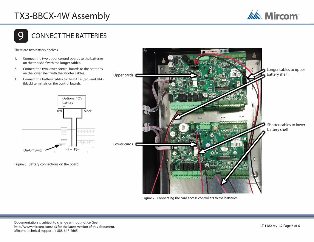
CONNECT THE BATTERIES
There are two battery shelves.
1. Connect the two upper control boards to the batteries on the top shelf with the longer cables.
2. Connect the two lower control boards to the batteries on the lower shelf with the shorter cables.
3. Connect the battery cables to the BAT + (red) and BAT - (black) terminals on the control boards.
Longer cables to upper battery shelf
Shorter cables to lower battery shelf
Figure 7: Connecting the card access controllers to the batteries
Upper cards
Lower cards
LT-1182 rev 1.2 Page 6 of 6
9
P5 + P6 -On/Off Switch
Optional 12 Vbattery -+
blackred
Figure 6: Battery connections on the board
TX3-BBCX-4W Assembly