two-step physical register deallocation for data
TRANSCRIPT

IPSJ Transactions on Advanced Computing Systems Vol. 1 No. 2 34–46 (Aug. 2008)
Regular Paper
Two-Step Physical Register Deallocation
for Data Prefetching and Address Pre-Calculation
Akihiro Yamamoto,†1,∗1 Yusuke Tanaka,†2
Hideki Ando†2 and Toshio Shimada†1
This paper proposes an instruction pre-execution scheme for a high per-formance processor, that reduces latency and early scheduling of loads. Ourscheme exploits the difference between the amount of instruction-level paral-lelism available with an unlimited number of physical registers and that avail-able with an actual number of physical registers. We introduce the two-stepphysical register deallocation scheme, which deallocates physical registers at therenaming stage as a first step, and eliminates pipeline stalls caused by a short-age of physical registers. Instructions wait for the final deallocation as a secondstep in the instruction window. While waiting, the scheme allows pre-executionof instructions, that enables prefetching of load data and early calculation ofmemory effective addresses. Our evaluation results show that our scheme im-proves the performance significantly, and achieves a 1.26 times speedup over aprocessor without a prefetcher. If combined with a stride prefetcher, it achievesa 1.18 times speedup over a processor with a stride prefetcher.
1. Introduction
The load latency in cycles becomes longer as the LSI technology advancesbecause the rate of improvement of memory access time is much slower thanthat of the processors clock frequency. The gap between the processor and thememory is often called a memory wall 30). A general method to reduce the latencydue to a memory wall is to fill the gap with several cache hierarchy levels, andto satisfy load requests at as a high a level as possible. However, this method isboth very costly and often insufficient.
Data prefetching is an alternative or additional method of solving this prob-lem. The method moves the necessary data, before it is actually used, from
†1 Department of Electrical Engineering and Computer Science, Nagoya University†2 Department of Computational Science and Engineering, Nagoya University∗1 Presently with Renesas Technology Corp.
a lower level to an upper level of the memory hierarchy in parallel with othercomputations, thus hiding the load latency. Many hardware schemes have beenproposed for prefetching 3),8),13),20),26). The schemes currently implemented inprocessors generally predict an access pattern, and prefetch data according tothe prediction when triggered by a cache miss. Although these schemes canbe implemented with a simple hardware, they are ineffective for irregular pat-terns that are difficult to predict. Schemes for irregular patterns have been pro-posed 2),5)–7),12),15),21),23),24),35),36), but they have disadvantages in that they arecostly to implement or require a multithreaded environment.
Even if the memory latency is perfectly hidden by prefetching, loads generallystill remain on the critical paths. The schedule timing is constrained by true datadependences, that arise from program semantics and so are difficult to remove.Some predictive schemes have been proposed that remove true dependences bypredicting a load address or a load value (e.g., last value predictor 16)). A commondisadvantage of these schemes is that it is difficult to achieve a sufficient improve-ment in performance without a complicated hardware for efficient recovery froma misprediction 22).
This paper proposes a scheme that provides an instruction pre-execution withina single thread for data prefetching and load address pre-calculation 31)–33). Ourscheme assumes a split load/store, where the load/store operation is split into anaddress calculation and a memory access. Our scheme creates a pre-executionstream that precedes the main execution stream that builds the architecturalstate. In general, instruction execution is constrained by dependences and re-source constraints. The precedence of the pre-execution stream is ensured byrelaxing the imposed resource constraint. Our scheme focuses on physical reg-isters as a resource constraint. Generally, a register file large enough to exploitfully the instruction-level parallelism (ILP) contained in a program is not im-plemented, because of space, time, and power constraints. This causes pipelinestalls at the register rename stage due to the shortage of physical registers. Toavoid such stalls, our scheme splits the physical register deallocation into twosteps at different pipeline stages. As a first step, the deallocation is carried outin the rename stage, which eliminates stalls at the rename stage and so the in-structions advance and are stored in the instruction window. Our scheme allows
34 c© 2008 Information Processing Society of Japan

35 Two-Step Physical Register Deallocation
those instructions to have a dry run (i.e., execution without write), forming thepre-execution stream. The final deallocation is carried out as a second step at thecommit stage, as in the conventional manner. This deallocation is notified to theinstructions that were allowed to use this physical register in the first step. Theseinstructions form the main execution stream that is allowed to write results.
Our pre-execution has two advantages. First, it realizes data prefetching. Ourprefetching relies on the actual execution, not on the prediction, and is thus effec-tive for memory accesses that are difficult to predict. Second, the pre-calculationof the load address removes the true dependence of a load during the main ex-ecution. Our pre-calculation of an address writes the result to the load/storequeue (LSQ). Thus, a load can immediately use the calculated address in themain execution, without having to wait for the address calculation.
The remainder of this paper is organized as follows. Section 2 illustrates theeffect of our scheme. Section 3 describes related work. Our pre-execution schemeis proposed in Section 4. Section 5 presents the evaluation results and finally,our conclusions are presented in Section 6.
2. Illustration of Effects
Figure 1 illustrates the effects of our pre-execution scheme. Figure 1 (a) showsan example of the execution timing of four dependent instructions in a conven-tional processor, where load occurs a cache miss. Figure 1 (b) shows the execu-tion timing of the same instructions with our pre-execution scheme. On the leftof this figure is the pre-execution stream, while the corresponding main execu-tion stream, not considering and considering the address pre-calculation effect,is shown on the middle and the right hand side of the figure, respectively. Asshown on the left of Fig. 1 (b), pre-execution starts earlier than the conventionalexecution because it is not stalled by the shortage of physical registers. Thus,the cache miss of load occurs earlier. Handling this cache miss moves data fromthe lower level of the memory subsystem to the upper level. As a result, in themain execution, load hits the L1 data cache, resulting in a speedup. Addresspre-calculation yields further speedup. The instruction acalc (address calcula-tion) is pre-executed and the generated address is written into the LSQ. As aresult, as shown on the right of Fig. 1 (b), in the main execution, the dependence
Fig. 1 Effect of our pre-execution scheme.
of load on acalc is resolved. Thus, load is executed further earlier.
3. Related Work
3.1 Data PrefetchingJouppi proposed a stream buffer that automatically prefetches contiguous lines,
succeeding a missed cache line, into the buffer 13). For a regular access pat-tern with a non-unit stride, stride prefetchers have been proposed 3),8),20). Suchautomatic prefetchers have considerable strength in prefetch timeliness if theaccess pattern has a constant stride. However, they are ineffective for irreg-ular patterns. Several prefetch schemes for irregular patterns have been pro-posed 12),15),23). These schemes generally hold irregular pattern information foreach missed address, and thus are very costly.
Our scheme is based on pre-execution. A number of studies based on pre-execution have been carried out 2),5)–7),21),24),35),36). These schemes extract, eitherstatically or dynamically, the instructions necessary for prefetching as a thread,and then spawn this thread at a certain point in the program execution to adifferent context of the processor. The disadvantage of these schemes is that they
IPSJ Transactions on Advanced Computing Systems Vol. 1 No. 2 34–46 (Aug. 2008) c© 2008 Information Processing Society of Japan

36 Two-Step Physical Register Deallocation
require a multithreaded environment such as simultaneous multithreading 29) orchip multiprocessors. Even in such an environment, a disadvantage arises in thatthe context is consumed; it may be more profitable to allocate other threads tothe context for a better throughput.
The only pre-execution scheme, to our knowledge, that does not need a mul-tithreaded environment is runahead execution 19). This scheme enters a specialmode called a runahead when an L2 cache miss occurs. In this mode, the archi-tectural state is checkpointed, and then succeeding instructions after the missedload are executed until the triggered miss is resolved. If another L2 cache missoccurs while in the runahead mode, the missed line is prefetched, overlappingmemory requests. The disadvantage of this scheme is the large overhead of modeswitching in both checkpointing and restarting. Therefore, its effectiveness is re-duced for cache misses with relatively small, yet still important latencies like L1cache misses. Furthermore, no computation can be overlapped with the triggeredL2 miss, because the computed results during the runahead mode are discardedon returning to the normal mode.
3.2 Elimination of Address Calculation DependenceLoad address prediction is effective in eliminating the true dependence between
an address calculation and a load. Value predictors 4),16),25) are used as an addresspredictor. The effectiveness of this predictive scheme depends on the predictionaccuracy and the efficiency of the recovery from mispredictions. A comprehen-sive performance evaluation was carried out by Reinman, et al.22). They foundthat a simple recovery method using pipeline squashing significantly reduces theeffectiveness, and a more elaborate method where only dependent instructionsare re-executed is necessary for the performance improvement to be sufficient.However, this complicates the issue logic, thus adversely affecting the clock cycletime.
3.3 Effectively Enlarging Register FileSeveral studies, aimed at effectively enlarging register files, have been done in
an attempt to reduce the occupation time of physical registers by a late alloca-tion 9),17) or an early deallocation 1),18),28) of these registers.
Early deallocation schemes deallocate registers speculatively by predicting alast consumer, and allocate them at the rename stage. The shortcomings of such
schemes include the large penalty imposed by a mis-speculation recovery, and therequirement of a large checkpointing register file that includes a shadow storage.
Late allocation schemes do not allocate registers at the rename stage; instead,they are allocated later in the pipeline. The virtual-physical register scheme 9),17)
allocates registers at the write-back stage. This scheme is similar to our scheme inthat instructions are executed even if physical registers have failed to be allocated,thus realizing pre-execution. Unfortunately, this scheme has a complication inavoiding a deadlock due to an out-of-order physical register allocation. A feasible,yet still complicated implementation imposes a considerable cycle count penalty,and causes a significant increase in the dynamic instruction counts by an ad hocregister reallocation and the resulting instruction’s re-execution. We compareour scheme with the virtual-physical register scheme in Section 5.6.
4. Pre-Execution Microarchitecture
Our scheme assumes a register renaming scheme, where the register file containscommitted values and temporary values for instructions that have been completedbut not yet committed, and a map table translates a logical register number intoa physical one. This type of register renaming is, for example, implementedin the MIPS R10000 34) and in the Digital Equipment Alpha 21264 14). In thissection, we first propose a two-step physical register deallocation scheme as thebasic scheme, and then extend this scheme to enable pre-execution.
4.1 Basic SchemeWe first describe the first-step deallocation, and then describe the second-step
deallocation.4.1.1 First-Step DeallocationThe first-step deallocation is performed in the rename stage. Besides the map
table and the free list, we prepare a table called the deallocation table (DAT).Each entry in the DAT is associated with a physical register, and holds a validbit and the number of the reorder buffer (ROB) entry, where the instruction thatfinally deallocates the corresponding physical register is placed.
The operations are as follows. First, when an instruction reaches the renamestage, the physical register that is currently allocated to the same logical des-tination register of the instruction is temporarily deallocated, and is appended
IPSJ Transactions on Advanced Computing Systems Vol. 1 No. 2 34–46 (Aug. 2008) c© 2008 Information Processing Society of Japan
37 Two-Step Physical Register Deallocation
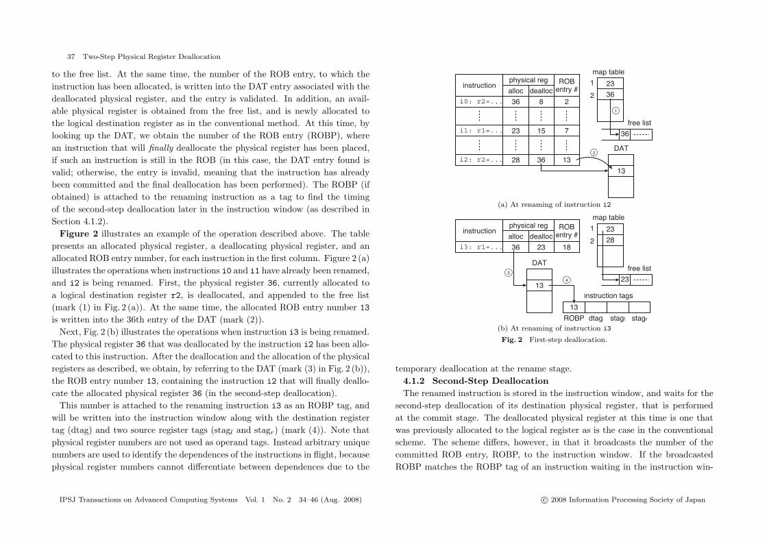
to the free list. At the same time, the number of the ROB entry, to which theinstruction has been allocated, is written into the DAT entry associated with thedeallocated physical register, and the entry is validated. In addition, an avail-able physical register is obtained from the free list, and is newly allocated tothe logical destination register as in the conventional method. At this time, bylooking up the DAT, we obtain the number of the ROB entry (ROBP), wherean instruction that will finally deallocate the physical register has been placed,if such an instruction is still in the ROB (in this case, the DAT entry found isvalid; otherwise, the entry is invalid, meaning that the instruction has alreadybeen committed and the final deallocation has been performed). The ROBP (ifobtained) is attached to the renaming instruction as a tag to find the timingof the second-step deallocation later in the instruction window (as described inSection 4.1.2).
Figure 2 illustrates an example of the operation described above. The tablepresents an allocated physical register, a deallocating physical register, and anallocated ROB entry number, for each instruction in the first column. Figure 2 (a)illustrates the operations when instructions i0 and i1 have already been renamed,and i2 is being renamed. First, the physical register 36, currently allocated toa logical destination register r2, is deallocated, and appended to the free list(mark (1) in Fig. 2 (a)). At the same time, the allocated ROB entry number 13
is written into the 36th entry of the DAT (mark (2)).Next, Fig. 2 (b) illustrates the operations when instruction i3 is being renamed.
The physical register 36 that was deallocated by the instruction i2 has been allo-cated to this instruction. After the deallocation and the allocation of the physicalregisters as described, we obtain, by referring to the DAT (mark (3) in Fig. 2 (b)),the ROB entry number 13, containing the instruction i2 that will finally deallo-cate the allocated physical register 36 (in the second-step deallocation).
This number is attached to the renaming instruction i3 as an ROBP tag, andwill be written into the instruction window along with the destination registertag (dtag) and two source register tags (stagl and stagr) (mark (4)). Note thatphysical register numbers are not used as operand tags. Instead arbitrary uniquenumbers are used to identify the dependences of the instructions in flight, becausephysical register numbers cannot differentiate between dependences due to the
(a) At renaming of instruction i2
(b) At renaming of instruction i3
Fig. 2 First-step deallocation.
temporary deallocation at the rename stage.4.1.2 Second-Step DeallocationThe renamed instruction is stored in the instruction window, and waits for the
second-step deallocation of its destination physical register, that is performedat the commit stage. The deallocated physical register at this time is one thatwas previously allocated to the logical register as is the case in the conventionalscheme. The scheme differs, however, in that it broadcasts the number of thecommitted ROB entry, ROBP, to the instruction window. If the broadcastedROBP matches the ROBP tag of an instruction waiting in the instruction win-
IPSJ Transactions on Advanced Computing Systems Vol. 1 No. 2 34–46 (Aug. 2008) c© 2008 Information Processing Society of Japan

38 Two-Step Physical Register Deallocation
Fig. 3 Instruction scheduler in our basic scheme.
dow, the write of the result is granted. Also, the DAT entry associated with thedeallocated physical register is invalidated.
In the example shown in Fig. 2, the second-step deallocation of the physicalregister 36 is performed when the instruction i2 is committed. The ROB entrynumber 13 is then broadcast to the instruction window. It is matched with theROBP tag of the instruction i3, and the result write of this instruction is granted.
The logic circuit of the instruction scheduler in our basic scheme is shown inFig. 3. The three tags, ROBP, stagl, and stagr, are held in the wakeup logic foreach instruction. The three flags, W, Rl, and Rr, associated with each tag arealso held. Flags Rl and Rr are the conventional ready flags indicating that thecorresponding source operands are available. Flag W indicates that the resultwrite of the corresponding instruction has been granted. When an instruction isissued, its destination tag, also called a result tag, is read from the tag RAM, andis broadcast to the wakeup logic. The tag match is checked with the comparator,and the ready flag is set if a match occurred as in the conventional scheme. Onthe other hand, the ROB entry number sent from the ROB is compared witheach ROBP tag, and the flag W is set if a match occurs. If flags W, Rl, and Rr
are all set, an issue request is sent to the select logic. If selected, the instruction
is executed and the result is written as in the normal method.Note that, for instructions that do not obtain a valid ROBP in the rename
stage, flag W is initially set when they are written into the instruction window.Since their destination physical register has already been finally deallocated, anissue control by the flag W is not necessary. Also, instructions that do nothave destination registers, such as the address calculation instructions of memoryinstructions, are controlled in the same manner, because these instructions do notrequire register writes.
4.2 Extension to Instruction Pre-ExecutionIn the previous section, we mentioned that instructions waiting in the instruc-
tion window are not allowed to be issued until their writes have been granted.However, it is possible for such instructions to be executed; although the exe-cution result is not written, it can be passed to dependent instructions via thebypass logic if the instructions are issued continuously. These instructions form apre-execution stream, which proceeds faster than the main execution stream be-cause it exploits ILP, where no resource constraint concerning physical registersexists.
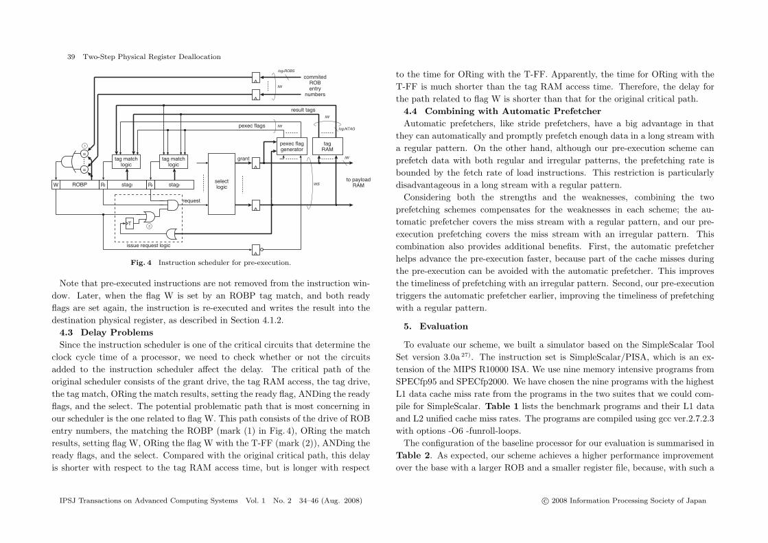
Figure 4 shows the logic circuit diagram of the instruction scheduler that im-plements our pre-execution scheme. The main differences between this extendedscheduler logic and the logic of the basic scheme shown in Fig. 3 are the following:1) A T-FF is placed in the issue request logic to allow the pre-execution only oncebefore a write is granted. 2) A flag we call pexec is attached to the result tag ofeach pre-executed instruction. This flag is used to reset the ready flag that wasset in the previous cycle.
When an instruction is written into the instruction window, the T-FF in thecorresponding entry is set. When the execution of an instruction finishes, itsresult tag is broadcast. The ready flag in the entry matching the tag is set.When both ready flags, Rl and Rr, are set, the issue request is sent to the selectlogic through the issue request logic, even if flag W is 0, because the T-FF is1. If the request is granted, the selected instruction is issued and pre-executed.The grant signal toggles the T-FF to 0, and thus an issue request will not beproduced until flag W has been set. Also, pexec flags are generated, and willreset the ready flags in the next cycle
IPSJ Transactions on Advanced Computing Systems Vol. 1 No. 2 34–46 (Aug. 2008) c© 2008 Information Processing Society of Japan
39 Two-Step Physical Register Deallocation
Fig. 4 Instruction scheduler for pre-execution.
Note that pre-executed instructions are not removed from the instruction win-dow. Later, when the flag W is set by an ROBP tag match, and both readyflags are set again, the instruction is re-executed and writes the result into thedestination physical register, as described in Section 4.1.2.
4.3 Delay ProblemsSince the instruction scheduler is one of the critical circuits that determine the
clock cycle time of a processor, we need to check whether or not the circuitsadded to the instruction scheduler affect the delay. The critical path of theoriginal scheduler consists of the grant drive, the tag RAM access, the tag drive,the tag match, ORing the match results, setting the ready flag, ANDing the readyflags, and the select. The potential problematic path that is most concerning inour scheduler is the one related to flag W. This path consists of the drive of ROBentry numbers, the matching the ROBP (mark (1) in Fig. 4), ORing the matchresults, setting flag W, ORing the flag W with the T-FF (mark (2)), ANDing theready flags, and the select. Compared with the original critical path, this delayis shorter with respect to the tag RAM access time, but is longer with respect
to the time for ORing with the T-FF. Apparently, the time for ORing with theT-FF is much shorter than the tag RAM access time. Therefore, the delay forthe path related to flag W is shorter than that for the original critical path.
4.4 Combining with Automatic PrefetcherAutomatic prefetchers, like stride prefetchers, have a big advantage in that
they can automatically and promptly prefetch enough data in a long stream witha regular pattern. On the other hand, although our pre-execution scheme canprefetch data with both regular and irregular patterns, the prefetching rate isbounded by the fetch rate of load instructions. This restriction is particularlydisadvantageous in a long stream with a regular pattern.
Considering both the strengths and the weaknesses, combining the twoprefetching schemes compensates for the weaknesses in each scheme; the au-tomatic prefetcher covers the miss stream with a regular pattern, and our pre-execution prefetching covers the miss stream with an irregular pattern. Thiscombination also provides additional benefits. First, the automatic prefetcherhelps advance the pre-execution faster, because part of the cache misses duringthe pre-execution can be avoided with the automatic prefetcher. This improvesthe timeliness of prefetching with an irregular pattern. Second, our pre-executiontriggers the automatic prefetcher earlier, improving the timeliness of prefetchingwith a regular pattern.
5. Evaluation
To evaluate our scheme, we built a simulator based on the SimpleScalar ToolSet version 3.0a 27). The instruction set is SimpleScalar/PISA, which is an ex-tension of the MIPS R10000 ISA. We use nine memory intensive programs fromSPECfp95 and SPECfp2000. We have chosen the nine programs with the highestL1 data cache miss rate from the programs in the two suites that we could com-pile for SimpleScalar. Table 1 lists the benchmark programs and their L1 dataand L2 unified cache miss rates. The programs are compiled using gcc ver.2.7.2.3with options -O6 -funroll-loops.
The configuration of the baseline processor for our evaluation is summarised inTable 2. As expected, our scheme achieves a higher performance improvementover the base with a larger ROB and a smaller register file, because, with such a
IPSJ Transactions on Advanced Computing Systems Vol. 1 No. 2 34–46 (Aug. 2008) c© 2008 Information Processing Society of Japan

40 Two-Step Physical Register Deallocation
Table 1 Cache miss rate.
miss ratesuite program
L1 data L2hyrdro2d 8% 31%
SPECfp95 su2cor 7% 0%wave5 4% 7%ammp 9% 32%applu 5% 49%art 48% 44%
SPECfp2000equake 5% 41%mgrid 3% 30%swim 13% 36%
Table 2 Baseline processor configuration.
Pipeline width 8-instruction wide for each of fetch, decode, issue, and commitROB 128 entriesInstruction window 64 entriesLSQ 64 entriesFunction unit 8 iALU, 4 iMULT/DIV, 4 Ld/St, 6 fpALU,
4 fpMULT/DIV/SQRTL1 I-cache 64KB, 2-way, 32B lineL1 D-cache 64KB, 2-way, 32B line, 4 ports, 2-cycle hit latency, non-blockingL2 cache 2MB, 4-way, 64B line, 12-cycle hit latencyMain memory 300-cycle minimum latency, 8B/cycle bandwidthBranch prediction 6-bit history gshare, 8K-entry PHT,
10-cycle misprediction penaltyPhysical register total 192 (96 for each of integer and floating-point)Mem. disambiguation perfect
configuration, many instructions stalls due to the shortage of physical registersin the conventional processor, while such instructions can be pre-executed withthe support of the large ROB in our scheme. For fair evaluation, we conserva-tively determined the relationship between the ROB and register file sizes, to bebalanced in the conventional microarchitecture. We used the following equation:
Npregs = ROB size + Nlregs (1)where Npregs and Nlregs are the total number of physical and logical registers,respectively. The ROB size and the number of physical registers determined byequation (1) are balanced in that 1) the ROB size gives the number of supportedin-flight instructions, and most in-flight instructions require a physical register,and 2) each committed logical destination register requires a physical register.
Table 3 Percentage of dynamic instructions categorized by type of destination register.
type of destination registerprogram
int fp other nonehydro2d 46% 28% 4% 21%su2cor 51% 32% 0% 16%wave5 41% 41% 2% 16%ammp 24% 55% 1% 20%applu 60% 31% 1% 8%art 37% 39% 2% 22%
equake 58% 16% 0% 26%mgrid 43% 55% 1% 2%swim 48% 48% 0% 4%AVG 45% 38% 1% 15%
Next, we divided the total number of physical registers equally between inte-ger and floating-point registers. This is reasonable as the number of dynamicinstructions with destination registers being either integer or floating point isroughly equal in the benchmark programs we used. Table 3 lists the percentageof dynamic instructions categorized by the type of the destination register inthe baseline processor. Finally, we determined the instruction window size andthe LSQ size to be half the ROB size. In Sections 5.4 and 5.5, we present theevaluation results showing the sensitivity of the ROB and the register file sizesto performance.
Finally, we also assume a perfect memory disambiguation for fair evaluation.Our pre-calculation of the load address has a positive effect on the memorydisambiguation. For fair evaluation, instead of implementing memory dependencepredictors in our base simulator, we assume a perfect memory disambiguation toexclude the effects on memory disambiguation.
5.1 Effect of Data PrefetchingWe evaluate the average load latency of the following three models. The first is
the stride prefetcher model, which is the baseline processor with a stride prefetcherusing a per-load stride predictor 8). It has a stream buffer 13) between the L1 datacache and the L2 unified cache to avoid the pollution of the L1 data cache. Thestream buffer is accessed in parallel with the L1 data cache, and the requesteddata is assumed to be obtained with a single cycle latency, if it is found. The con-figuration of the stream buffer is determined based on the hardware prefetching
IPSJ Transactions on Advanced Computing Systems Vol. 1 No. 2 34–46 (Aug. 2008) c© 2008 Information Processing Society of Japan

41 Two-Step Physical Register Deallocation
Fig. 5 Average load latency.
scheme of an Intel Pentium 4 11). The buffer has eight ways, the capacity of eachbeing 4 KB each, and the line size 32B. The buffer is allocated on an L1 datacache miss. To suppress prefetching of useless data, the incremental prefetchingscheme 8) proposed by Farkas et al. is introduced.
The second model is the pre-execution model, which incorporates our pre-execution scheme into the baseline processor. A stream buffer is not placed.
The third model is a hybrid model that combines the pre-execution and thestride prefetcher models.
Figure 5 shows the average load latency for each model. As shown in thefigure, the pre-execution model reduces the load latency significantly comparedto the base model for many programs.
Intuitively, the effectiveness of the pre-execution model depends on how wellpre-execution is performed. In other words, the effectiveness correlates to howwell pre-execution is performed. To confirm this, we introduce the followingmetric, which we call precedence cycles per load (PCPL):
PCPL =
∑
pre−executed load
precedence cycles
total number of loadswhere precedence cycles is defined as how many cycles the pre-execution of a
Fig. 6 Correlation between load latency reduction rate and precedence cycles per load.
load is earlier than the main execution of the load. Note that we focus only oncommitted loads in this definition. PCPL becomes larger as more loads are pre-executed and/or the number of precedence cycles in a pre-executed load grows.
Figure 6 shows the correlation between the load latency reduction rate fromthe base and PCPL. As expected, a correlation can be confirmed, although itis weak. The reason that the correlation is weak is that the contribution to theload latency reduction depends on whether or not pre-executed loads incur acache miss and at which level the miss occurs. This weak correlation indicatesthe inefficiency of our data prefetching in terms of power consumption, becauseuseless pre-execution may be performed. If we can focus on loads that incur acache miss and pre-execute only the instructions related to such loads, a moreefficient pre-execution will be achieved. This is our work in progress 10).
Let us return to Fig. 5. Compared with the stride prefetcher model, the pre-execution model is better in art, and comparable in su2cor and ammp. However,in other programs, the stride prefetcher model performs better than the pre-execution model. Figure 7 shows the hit rate of the stream buffer for missedaccesses to the L1 data cache in the stride prefetcher model. The lower andupper portions of each bar represent full and partial hits, respectively. In manyprograms, the stride prefetcher performs well, and thus it is difficult for the pre-
IPSJ Transactions on Advanced Computing Systems Vol. 1 No. 2 34–46 (Aug. 2008) c© 2008 Information Processing Society of Japan

42 Two-Step Physical Register Deallocation
Fig. 7 Stream buffer hit rate.
execution model to outperform the stride prefetcher model on average. However,it is also a fact that misses it cannot cover remain in many programs.
The hybrid model covers those remaining misses with our pre-execution, andthus exhibits the lowest load latency of the four evaluated models for most pro-grams. In particular, in ammp and art, the hybrid model significantly reducesthe load latency when compared to both the stride prefetcher model and thepre-execution model.
5.2 Effect of Address Pre-CalculationHere, we evaluate the effect of address pre-calculation. To exclude the prefetch
effect, we assume that the L1 data cache is perfect in the evaluation in this section.Figure 8 shows the speedup of the pre-execution model over the baseline model,with a perfect L1 data cache for both models. As shown in Fig. 8, the speedup isless than 10% in most programs, but a significant speedup is attained in mgridand swim.
5.3 Overall PerformanceWe now evaluate the overall performance of our scheme. Figure 9 compares
the IPC of the four models. As shown in this figure, our pre-execution modelachieves a speedup of 26% on average over the base model. Note that our schemeachieves this significant speedup with a modest hardware cost and with little
Fig. 8 Effect of address pre-calculations.
Fig. 9 Overall performance.
adverse impact on the clock cycle time. Although the performance of the pre-execution alone is 27% worse than that of the stride prefetcher model on average,the hybrid model exhibits a considerably better performance. The speedup overthe stride prefetcher model is 18%.
5.4 Performance Sensitivity to the Balance between Register FileSize and ROB Size
As stated before, the effectiveness of our scheme is sensitive to the balance
IPSJ Transactions on Advanced Computing Systems Vol. 1 No. 2 34–46 (Aug. 2008) c© 2008 Information Processing Society of Japan
43 Two-Step Physical Register Deallocation
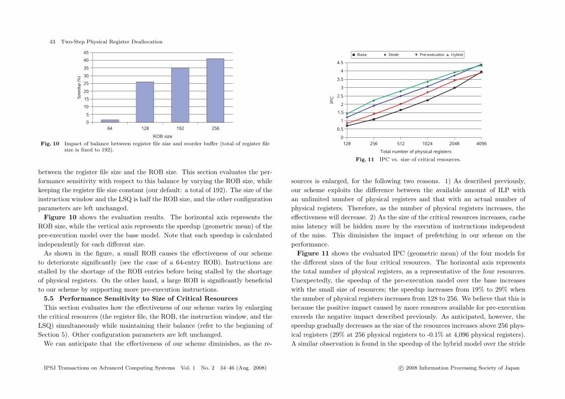
Fig. 10 Impact of balance between register file size and reorder buffer (total of register filesize is fixed to 192).
between the register file size and the ROB size. This section evaluates the per-formance sensitivity with respect to this balance by varying the ROB size, whilekeeping the register file size constant (our default: a total of 192). The size of theinstruction window and the LSQ is half the ROB size, and the other configurationparameters are left unchanged.
Figure 10 shows the evaluation results. The horizontal axis represents theROB size, while the vertical axis represents the speedup (geometric mean) of thepre-execution model over the base model. Note that each speedup is calculatedindependently for each different size.
As shown in the figure, a small ROB causes the effectiveness of our schemeto deteriorate significantly (see the case of a 64-entry ROB). Instructions arestalled by the shortage of the ROB entries before being stalled by the shortageof physical registers. On the other hand, a large ROB is significantly beneficialto our scheme by supporting more pre-execution instructions.
5.5 Performance Sensitivity to Size of Critical ResourcesThis section evaluates how the effectiveness of our scheme varies by enlarging
the critical resources (the register file, the ROB, the instruction window, and theLSQ) simultaneously while maintaining their balance (refer to the beginning ofSection 5). Other configuration parameters are left unchanged.
We can anticipate that the effectiveness of our scheme diminishes, as the re-
Fig. 11 IPC vs. size of critical resources.
sources is enlarged, for the following two reasons. 1) As described previously,our scheme exploits the difference between the available amount of ILP withan unlimited number of physical registers and that with an actual number ofphysical registers. Therefore, as the number of physical registers increases, theeffectiveness will decrease. 2) As the size of the critical resources increases, cachemiss latency will be hidden more by the execution of instructions independentof the miss. This diminishes the impact of prefetching in our scheme on theperformance.
Figure 11 shows the evaluated IPC (geometric mean) of the four models forthe different sizes of the four critical resources. The horizontal axis representsthe total number of physical registers, as a representative of the four resources.Unexpectedly, the speedup of the pre-execution model over the base increaseswith the small size of resources; the speedup increases from 19% to 29% whenthe number of physical registers increases from 128 to 256. We believe that this isbecause the positive impact caused by more resources available for pre-executionexceeds the negative impact described previously. As anticipated, however, thespeedup gradually decreases as the size of the resources increases above 256 phys-ical registers (29% at 256 physical registers to -0.1% at 4,096 physical registers).A similar observation is found in the speedup of the hybrid model over the stride
IPSJ Transactions on Advanced Computing Systems Vol. 1 No. 2 34–46 (Aug. 2008) c© 2008 Information Processing Society of Japan

44 Two-Step Physical Register Deallocation
model. Although our scheme becomes ineffective with an impractically large sizeof the critical resources, it is sufficiently effective over a wide range of the sizesof the critical resources.
5.6 Comparison with Virtual-Physical Register SchemeAs described in Section 3.3, the virtual-physical (VP) scheme has the ability
to prefetch data as in our scheme. Here, we compare our scheme with the VPscheme, which employs DSY (on-demand with steeling from younger)17) to avoidany deadlock. We introduce two models for the VP scheme with different cyclesconsumed for register reallocation in the DSY. One is an ideal DSY model, whichis ideal in that no cycle is consumed for register reallocation. The other is a realDSY model, which limits the ROB read bandwidth to the commit width (eightin our assumption) when searching for a victim to reallocate a register and stallsthe execution and commit stages of the pipeline while searching (the memorysubsystem is not stalled).
Figure 12 (a) shows the IPCs. As shown in this figure, the IPC of our schemeis comparable with the ideal DSY. However, taking into account the registerreallocation cost, the real DSY model significantly degrades the performance. Inaddition, the VP scheme considerably increases the dynamic instruction count,as shown in Fig. 12 (b) (the vertical axis indicates the percent increase of thedynamic instruction count over the committed instruction count). This increasespower consumption.
6. Conclusions
In this paper, we have proposed a scheme that prefetches data and pre-calculates the address of loads. Our scheme allows instructions to be pre-executedin a single context by exploiting the difference between the available amount ofILP without resource constraints of the physical registers and that of ILP withthese constraints. Execution-based data prefetching enables prefetching of datawith an irregular access pattern. Our scheme is implemented by a simple tablethat maintains early register deallocation and a modestly modified instructionscheduler. Our evaluation results show that our scheme significantly improvesthe performance by 26% over a processor without a prefetcher. Considering thestrength of an automatic prefetcher for a regular access pattern, we believe that
(a) IPC
(b) Dynamic instruction count increase
Fig. 12 Comparison with virtual-physical register scheme.
combining it with our scheme offers its best use. The combined scheme improvesthe performance by 18% over a processor incorporating only a stride prefetcher.
Acknowledgments This work was partially supported by The Ministry ofEducation, Culture, Sports, Science and Technology Grant-in-Aid for ScientificResearch (C)(No.19500041).
References
1) Balkan, D., Sharkey, J., Ponomarev, F. and Aggarwal, A.: Address-Value De-coupling for Early Register Deallocation, Proc. 2006 International Conference on
IPSJ Transactions on Advanced Computing Systems Vol. 1 No. 2 34–46 (Aug. 2008) c© 2008 Information Processing Society of Japan

45 Two-Step Physical Register Deallocation
Parallel Processing , pp.337–346 (2006).2) Chappell, R., Stark, J., Kim, S., Reinhardt, S. and Patt, Y.: Simultaneous Sub-
ordinate Microthreading (SSMT), Proc. 26th Annual International Symposium onComputer Architecture, pp.186–195 (1999).
3) Chen, T.F. and Baer, J.L.: Reducing Memory Latancy via Non-Blocking andPrefetching Caches, Proc. Fifth Annual International Conference on ArchitecturalSupport for Programming Languages and Operating Systems, pp.51–61 (1992).
4) Chen, T.F. and Baer, J.L.: Effective Hardware-based Data Prefetching for HighPerformance Processors, IEEE Transactions on Computers, Vol.44, No.5, pp.609–623 (1995).
5) Collins, J.D., Sair, S., Calder, B. and Tullsen, D.M.: Pointer Cache AssistedPrefetching, Proc. 35th Annual International Symposium on Microarchitecture,pp.62–73 (2002).
6) Collins, J.D., Tullsen, D.M., Wang, H., Lee, Y., Lavery, D., Shen, J.P. and Hughes,C.: Speculative Precomputation: Long-Range Prefetching of Delinquent Loads,Proc. 28th Annual International Symposium on Computer Architecture, pp.14–25(2001).
7) Collins, J.D., Tullsen, D.M., Wang, H. and Shen, J.P.: Dynamic Speculative Pre-computation, Proc. 34th Annual International Symposium on Microarchitecture,pp.306–317 (2001).
8) Farkas, I., Chow, P., Jouppi, N.P. and Vranesic, Z.: Memory-System Design Con-siderations for Dynamically-scheduled Processors, Proc. 24th Annual InternationalSymposium on Computer Architecture, pp.133–143 (1997).
9) Gonzalez, A., Gonzalez, J. and Valero, M.: Virtual-Physical Registers, Proc. fourthAnnual International Symposium on High Performance Computing , pp.175–184(1998).
10) Hyodo, K. and Ando, H.: A Low-Power Design of Instruction Pre-Execution Mech-anism with Two-Step Physical Register Deallocation, IPSJ SIG Technical Reports,Vol.2007-ARC-174, pp.169–174 (2007).
11) Intel Corporation: Intel Pentium 4 Processor Optimization Reference Manual(1999).
12) Joseph, D. and Grunwald, D.: Prefetching using Markov Predictors, Proc. 24thAnnual International Symposium on Computer Architecture, pp.252–263 (1997).
13) Jouppi, N.P.: Improving Direct-Mapped Cache Performance by the Addition ofa Small Fully Associative Cache and Prefetch Buffers, Proc. 17th Annual Interna-tional Symposium on Computer Architecture, pp.364–373 (1990).
14) Kessler, R.E.: The Alpha 21264 Microprocessor, IEEE Micro, Vol.19, No.2, pp.24–36 (1999).
15) Lai, A., Fide, C. and Falsafi, B.: Dead-Block Prediction and Dead-Block Corre-lating Prefetchers, Proc. 28th Annual International Symposium on Computer Ar-chitecture, pp.144–154 (2001).
16) Lipasti, M.H., Wilkerson, C.B. and Shen, J.P.: Value Locality and Load ValuePrediction, Proc. Seventh Intenational Conference on Architecture Support for Pro-gramming Languages and Operating Systems, pp.138–147 (1996).
17) Monreal, T., Gonzalez, A., Valero, M., Gonzalez, J. and Vinals, V.: Delaying Phys-ical Register Allocation through Virtual-Physical Registers, Proc. 32nd Annual In-ternational Symposium on Microarchitecture, pp.186–192 (1999).
18) Moudgill, M., Pinagli, K. and Vassiliadis, S.: Register Renaming and DynamicSpeculation: An Alternative Approach, Proc. 26th Annual International Symposiumon Microarchitecture, pp.202–213 (1993).
19) Mutlu, O., Stark, J., Wilkerson, C. and Patt, Y.N.: Runahead Execution: An Effec-tive Alternative to Large Instruction Windows, Proc. Nineth Annual InternationalSymposium on High-Performance Computer Architecture, pp.129–140 (2003).
20) Palacharla, S. and Kessler, R.E.: Evaluating Stream Buffers as a Secondary CacheReplacement, Proc. 21st Annual International Symposium on Computer Architec-ture, pp.24–33 (1994).
21) Purser, Z., Sundaramoorthy, K. and Rotenberg, E.: A Study of Slipstream Proces-sors, Proc. 33rd Annual International Symposium on Microarchitecture, pp.269–280(2000).
22) Reinman, G. and Calder, B.: Predictive Techniques for Aggressive Load Specula-tion, Proc. 31st International Symposium on Microarchitecture, pp.127–137 (1998).
23) Roth, A. and Sohi, G.S.: Effective Jump-Pointer Prefetching for Linked DataStructures, Proc. 26th Annual International Symposium on Computer Architecture,pp.111–121 (1999).
24) Roth, A. and Sohi, G.S.: Speculative Data-driven Multithreading, Proc. 7th An-nual International Symposium on High Performance Computer Architecture, pp.37–48 (2001).
25) Sazeides, Y. and Smith, J.E.: The Predictability of Data Values, Proc. 30th Inter-national Symposium on Microarchitecture, pp.248–258 (1997).
26) Sherwood, T., Sair, S. and Calder, B.: Predictor-Directed Stream Buffers, Proc.33rd Annual International Symposium on Microarchitecture, pp.42–53 (2000).
27) http://www.simplescalar.com/.28) Srinivasan, S.T., Rajwar, R., Akkary, H., Gandhi, A. and Upton, M.: Continual
Flow Pipelines, Proc. 11th International Conference on Architectural Support forProgramming Languages and Operating Systems, pp.107–119 (2004).
29) Tullsen, D.M., Eggers, S. and Levy, H.M.: Simultaneous Multithreading: Maximiz-ing On-Chip Parallelism, Proc. 22nd Annual International Symposium on ComputerArchitecture, pp.392–403 (1995).
30) Wulf, W.A. and McKee, S.A.: Hitting the Memory Wall: Implications of the Obvi-ous, ACM SIGARCH Computer Architecture News, Vol.23, No.1, pp.20–24 (1995).
31) Yamamoto, A., Ando, H. and Shimada, T.: Two-Step Physical Register Dealloca-tion for Superscalar Processors, IPSJ SIG Technical Reports, Vol.2005-ARC-164,
IPSJ Transactions on Advanced Computing Systems Vol. 1 No. 2 34–46 (Aug. 2008) c© 2008 Information Processing Society of Japan

46 Two-Step Physical Register Deallocation
pp.7–12 (2005).32) Yamamoto, A., Ando, H. and Shimada, T.: Latency Reduction and Precise
Scheduling of Loads through Pre-Execution, Symposium on Advanced ComputingSystems and Infrastructures, pp.403–410 (2006).
33) Yamamoto, A., Tanaka, Y., Ando, H. and Shimada, T.: Data Prefetching and Ad-dress Pre-Calculation through Instruction Pre-Execution with Two-Step PhysicalRegister Deallocation, Proc. Eighth Workshop on Memory Performance: Dealingwith Applications, Systems and Architectures, pp.41–48 (2007).
34) Yeager, K.C.: The MIPS R10000 Superscalar Microprocessor, IEEE Micro, Vol.16,No.2, pp.28–40 (1996).
35) Zilles, C. and Sohi, G.S.: Master/Slave Speculative Parallelization, Proc. 35th An-nual International Symposium on Microarchitecture, pp.85–96 (2002).
36) Zilles, C.B. and Sohi, G.S.: Execution-Based Prediction using Speculative Slices,Proc. 28th Annual International Symposium on Computer Architecture, pp.2–13(2001).
(Received January 14, 2008)(Accepted March 21, 2008)
Akihiro Yamamoto was born in 1981. He received his B.E.and M.E. degrees from Nagoya University in 2004 and 2006, re-spectively. Since 2006, he has been engaged in development onSoC at Car Information System Design Department, RenesasTechnology Corp.
Yusuke Tanaka received his B.E. degree from Nagoya Univer-sity in 2006. He is currently a graduate student of the departmentof computational science and engineering of Nagoya University.His research interests include computer architectures.
Hideki Ando received his B.S. and M.S. degrees in electronicengineering from Osaka University, Suita, Japan in 1981 and 1983,respectively. He received a Ph.D. degree in information sciencefrom Kyoto University, Kyoto, Japan in 1996. From 1983 to 1997he was engaged in the research and development of digital sig-nal processors for ISDN, microprocessors for inference machinesof the Japanese fifth-generation computer systems project, and
general-purpose VLIW machines at the LSI Research and Development Labora-tory, Mitsubishi Electric Corporation, Itami, Japan. From 1991 to 1992 he wasa visiting scholar at Stanford University. In 1997 he joined the faculty of NagoyaUniversity, Nagoya, Japan, where he is currently a professor in the departmentof computational science and engineering. In 1998 and 2002, he received theIPSJ best paper awards. His research interests include computer architectureand compilers.
Toshio Shimada received his B.S. and M.S. degrees in Math-ematical Engineering and Instrumentation Physics in 1968 and1970 respectively from the University of Tokyo. He received hisPhD degree in Information Science and Technology in 1992 fromthe University of Tokyo. He had worked at Electrotechnical Lab-oratory from 1970 to 1992. He is currently a professor at NagoyaUniversity. Dr. Shimada’s research interests involve low power
consumption processors and special purpose LSI.
IPSJ Transactions on Advanced Computing Systems Vol. 1 No. 2 34–46 (Aug. 2008) c© 2008 Information Processing Society of Japan