two-phase loop: compact thermosyphon - hp labs · when charging the thermosyphon loop with the...
TRANSCRIPT
Two-Phase Loop: Compact Thermosyphon Monem H. Beitelmal, Chandrakant D. Patel Internet Systems and Storage Laboratory HP Laboratories Palo Alto HPL-2002-6 January 11th , 2002* liquid loop, thermosyphon, passive cooling loop
Power density of future microprocessors is projected to reach over 100 W/cm2. Shrinking system size, the need to integrate more components within limited space, and customer demand to reduce system acoustic noise present significant challenges to the thermal designer. Thermosyphon technology provides a promising solution to these thermal challenges. Conventional heat sink capability to overcome the new thermal challenges is limited. Refrigeration and spray cooling can provide a solution to the thermal challenges posed by the higher power density, however reliability issues are still unresolved making these solutions impractical for the current challenges. Loop thermosyphon provides the benefits of using liquid cooling for microprocessor. It is a two-phase passive cooling loop that uses liquid as a working fluid. The loop between the evaporator and the condenser results in separate vapor and condensate path. It is considered to be a compact thermal management device due to its flexibility in size and cooling capacity range. This report presents HP Laboratories loop thermosyphon prototype and the experimental results of its thermal performance.
* Internal Accession Date Only Approved for External Publication Copyright Hewlett-Packard Company 2002
2
TABLE OF CONTENTS
Page
Abstract 1
Table of Contents 2
1. Introduction 3
1.1 Objective 3
1.2 Background 3
1.3 Micro-Fabricated Boiling Enhanced Structure 5
2. Compact Thermosyphon Demonstration Vehicle 8
2.1 Objective 8
2.2 Prototype Design Specifications 8
2.3 Design Concept 8
2.4 Removing Non-Condensable 9
2.5 Working Fluid 9
2.6 The Final Prototype 10
3. Investigation on the Performance of the Loop Thermosyphon 12
3.1 Inclination Effects 12
3.1.1 Experimental Method and Apparatus 12
3.1.2 Results and Discussion 14
3.2 HP Vectra VL800 System Test 17
3.3 Vertical Arrangement (Right Angle) Test 19
3.4 Summary and Conclusions 20
Acknowledgement 21
References 22
3
CHAPTER 1 INTRODUCTION
1.1 Objective
Heat dissipation from high performance microprocessors is approaching 100
W/cm2. At this level, conventional cooling solution cannot match the demand from these
high performance components. This report presents a new way to resolve the thermal
challenges by developing and implementing an innovative low cost compact loop
thermosyphon.
A passive loop thermosyphon cooling system is described in conjunction with a
demonstration vehicle built for HP Vectra VL800. The additional goal of the loop
thermosyphon in the Vectra VL800 is to reduce acoustic noise in the system by
eliminating the existing heat sink fan.
1.2 Background
A loop thermosyphon [1] is a two-phase passive loop that uses liquid as a working
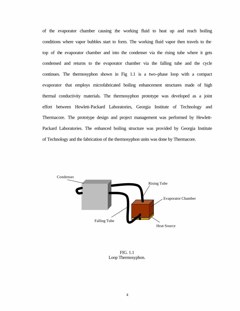
fluid for indirect and direct cooling. The loop thermosyphon as shown in Fig. 1.1 consists
of an evaporator chamber, a vapor outlet tube called a rising tube exiting the top of the
evaporator chamber, a condenser and a falling tube connecting the condenser outlet with
the evaporator inlet. The evaporator chamber houses a boiling enhancement structure
soldered to the inside surface of the evaporator bottom. It is a closed loop with water at
reduced pressure or a dielectric fluid similar to FC72 or PF5060 as its working fluid.
Using a dielectric fluid allows one to contemplate direct cooling with the microprocessor.
The system removes the heat from the microprocessor by interfacing through the bottom
4
of the evaporator chamber causing the working fluid to heat up and reach boiling
conditions where vapor bubbles start to form. The working fluid vapor then travels to the
top of the evaporator chamber and into the condenser via the rising tube where it gets
condensed and returns to the evaporator chamber via the falling tube and the cycle
continues. The thermosyphon shown in Fig 1.1 is a two-phase loop with a compact
evaporator that employs microfabricated boiling enhancement structures made of high
thermal conductivity materials. The thermosyphon prototype was developed as a joint
effort between Hewlett-Packard Laboratories, Georgia Institute of Technology and
Thermacore. The prototype design and project management was performed by Hewlett-
Packard Laboratories. The enhanced boiling structure was provided by Georgia Institute
of Technology and the fabrication of the thermosyphon units was done by Thermacore.
FIG. 1.1 Loop Thermosyphon.
Evaporator Chamber
Condenser
Falling Tube
Rising Tube
Heat Source
5
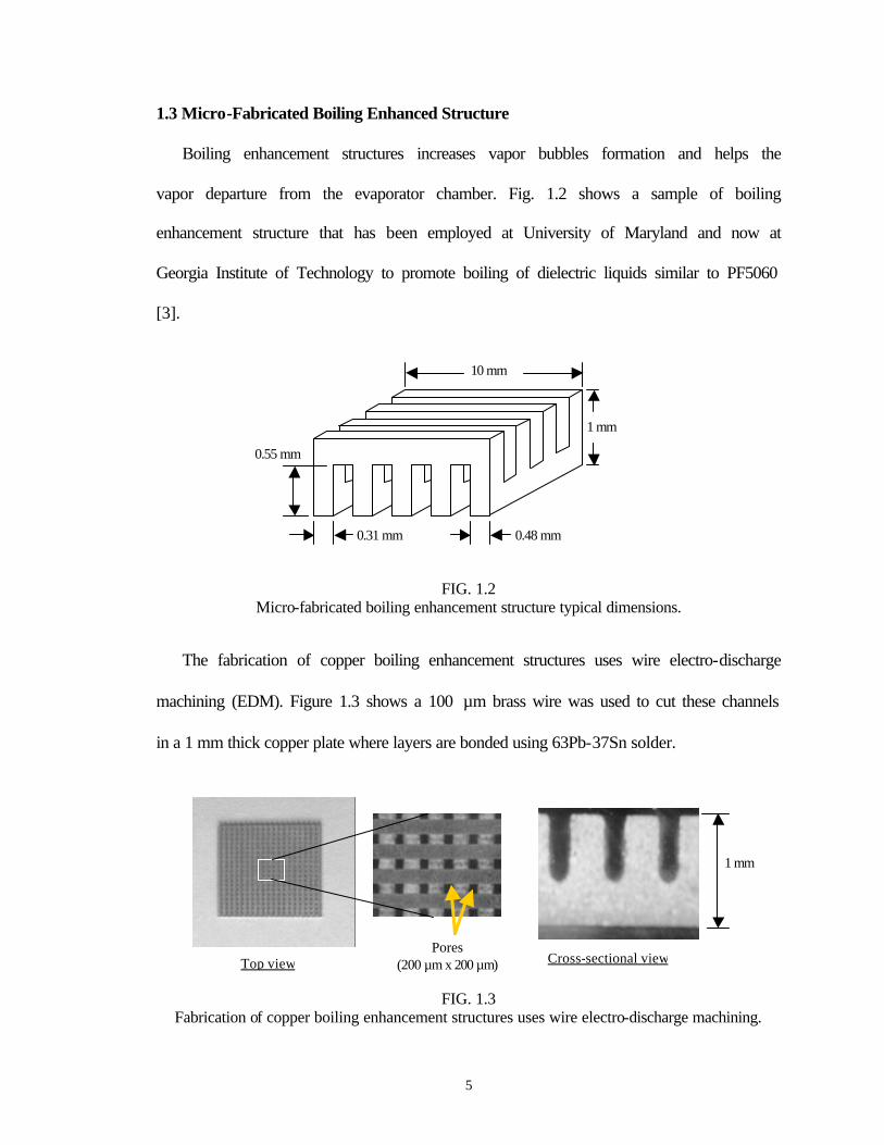
1.3 Micro-Fabricated Boiling Enhanced Structure
Boiling enhancement structures increases vapor bubbles formation and helps the
vapor departure from the evaporator chamber. Fig. 1.2 shows a sample of boiling
enhancement structure that has been employed at University of Maryland and now at
Georgia Institute of Technology to promote boiling of dielectric liquids similar to PF5060
[3].
FIG. 1.2 Micro-fabricated boiling enhancement structure typical dimensions.
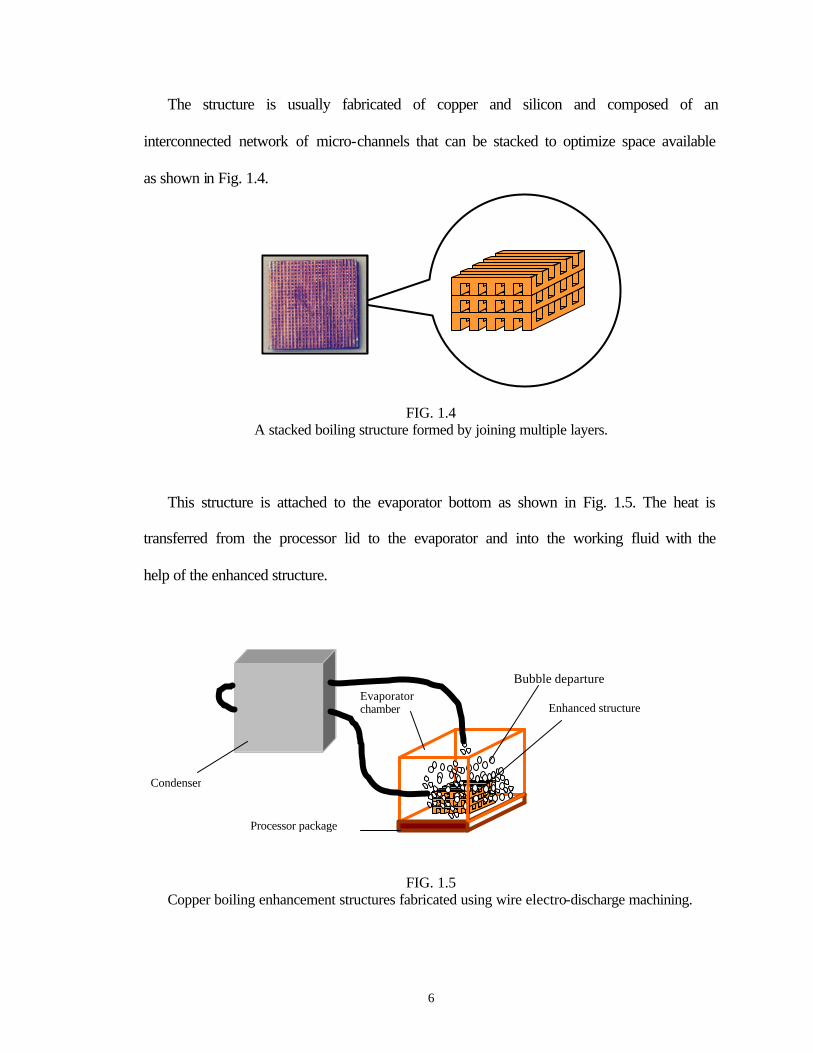
The fabrication of copper boiling enhancement structures uses wire electro-discharge
machining (EDM). Figure 1.3 shows a 100 µm brass wire was used to cut these channels
in a 1 mm thick copper plate where layers are bonded using 63Pb-37Sn solder.
FIG. 1.3
Fabrication of copper boiling enhancement structures uses wire electro-discharge machining.
Top view Cross-sectional view Pores
(200 µm x 200 µm)
1 mm
10 mm
1 mm
0.55 mm
0.31 mm 0.48 mm
6
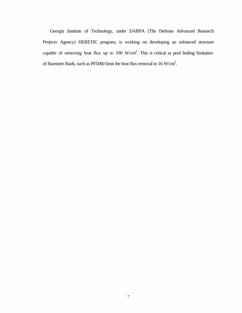
The structure is usually fabricated of copper and silicon and composed of an
interconnected network of micro-channels that can be stacked to optimize space available
as shown in Fig. 1.4.
FIG. 1.4
A stacked boiling structure formed by joining multiple layers.
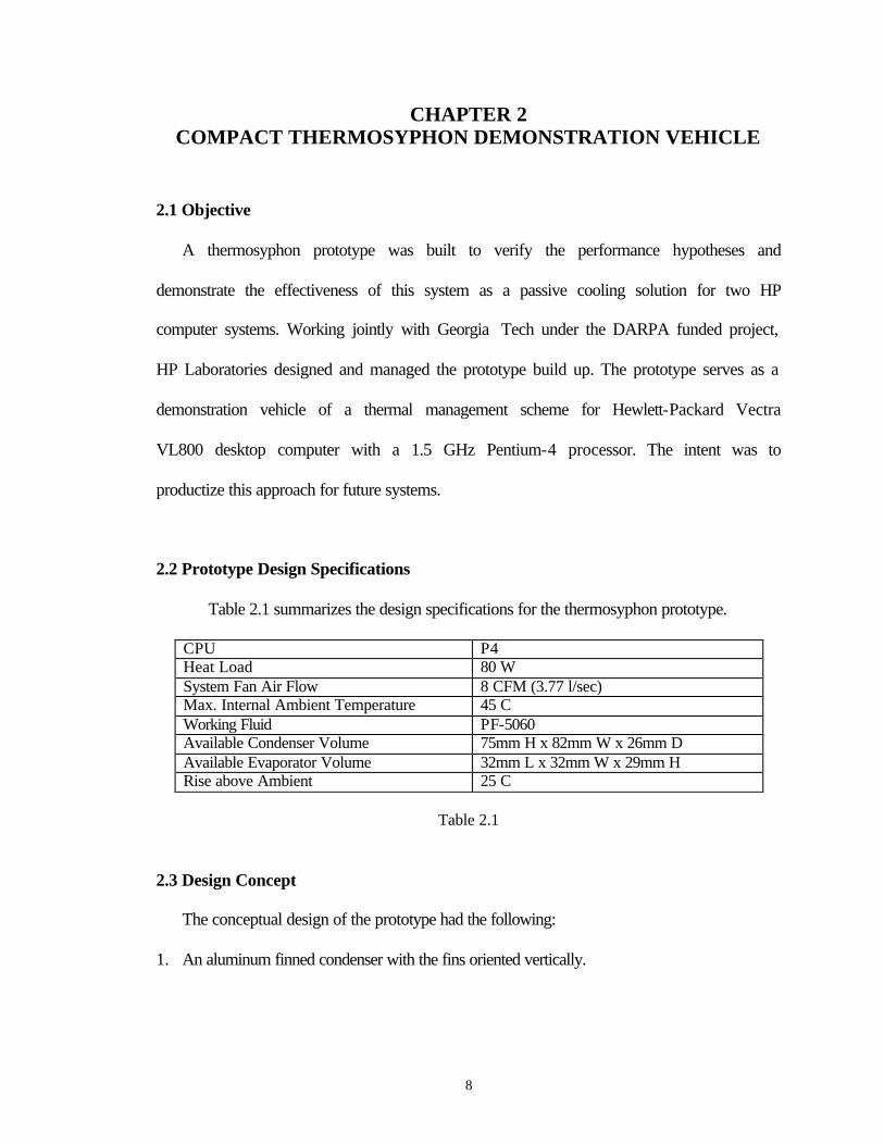
This structure is attached to the evaporator bottom as shown in Fig. 1.5. The heat is
transferred from the processor lid to the evaporator and into the working fluid with the
help of the enhanced structure.
FIG. 1.5
Copper boiling enhancement structures fabricated using wire electro-discharge machining.
Enhanced structure
Condenser
Bubble departure Evaporator
chamber
Processor package
7
Georgia Institute of Technology, under DARPA (The Defense Advanced Research
Projects Agency) HERETIC program, is working on developing an enhanced structure
capable of removing heat flux up to 100 W/cm2. This is critical as pool boiling limitation
of fluorinert fluids, such as PF5060 limit the heat flux removal to 16 W/cm2.
8
CHAPTER 2 COMPACT THERMOSYPHON DEMONSTRATION VEHICLE
2.1 Objective
A thermosyphon prototype was built to verify the performance hypotheses and
demonstrate the effectiveness of this system as a passive cooling solution for two HP
computer systems. Working jointly with Georgia Tech under the DARPA funded project,
HP Laboratories designed and managed the prototype build up. The prototype serves as a
demonstration vehicle of a thermal management scheme for Hewlett-Packard Vectra
VL800 desktop computer with a 1.5 GHz Pentium-4 processor. The intent was to
productize this approach for future systems.
2.2 Prototype Design Specifications
Table 2.1 summarizes the design specifications for the thermosyphon prototype.
CPU P4 Heat Load 80 W System Fan Air Flow 8 CFM (3.77 l/sec) Max. Internal Ambient Temperature 45 C Working Fluid PF-5060 Available Condenser Volume 75mm H x 82mm W x 26mm D Available Evaporator Volume 32mm L x 32mm W x 29mm H Rise above Ambient 25 C
Table 2.1
2.3 Design Concept
The conceptual design of the prototype had the following:
1. An aluminum finned condenser with the fins oriented vertically.
9
2. A copper rising tube for vapor outlet exiting the top of the evaporator chamber and
entering the side of the condenser.
3. A copper falling tube to return the condensed liquid to the side of the evaporator.
4. An evaporator chamber made of copper that houses the boiling enhancement
structure.
Copper was used to fabricate the evaporator chamber and the tube because of its
compatibility with the working fluid and ease of manufacturability. Moreover, copper
tubing is easily bent making it easy to configure the thermosyphon into the available
space inside a given computer system.
2.4 Removing Non-Condensable
Non-condensable such as air degrades thermosyphon performance. Care is required
when charging the thermosyphon loop with the working fluid. During charging, the
thermosyphon loop is brought to full operation by heating the evaporator chamber. Once
the thermosyphon is in full operation, the non-condensable (air) is pushed to the elevated
condenser where it is removed through a valve. This process is repeated until all non-
condensables are removed from the system. Loss of some of the working fluid occurs
during this procedure.
2.5 Working Fluid
The rule of thumb used by Thermacore Inc. requires that the working fluid height is
three times the height of the enhanced structure. For the Vectra VL800, the enhanced
structure height was 0.2 inch (~ 5mm) and the working fluid level was set at 0.6 inch (~
10
15mm). The thermosyphon charge amounts to 10 to 15 percent of the total volume
available inside the evaporator chamber. That corresponds to about 8 cm3 for the Vectra
VL800 PC.
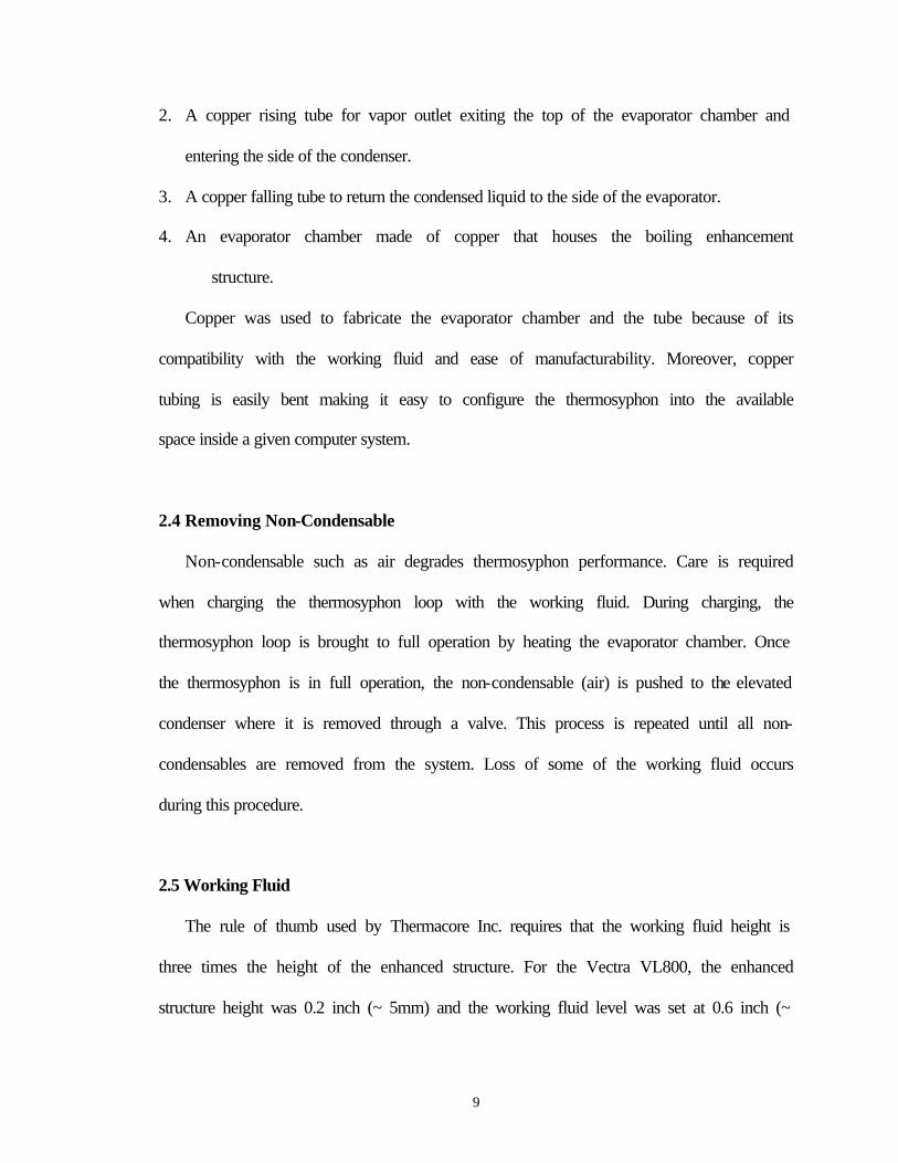
2.6 The Final Prototype
The final thermosyphon prototype for the Vectra VL800 PC is shown in Fig. 2.1. The
condenser was made of forty-five 3003-H14-aluminum fins with a surface area of 35 x 80
mm2 oriented vertically. The evaporator dimension was 25 x 25 x 25 mm3 with a base of
30 x 30 x 2 mm3. The working fluid used for this prototype was a dielectric coolant
PF5060 with a boiling temperature of 56 oC at atmospheric pressure.
FIG. 2.1 Digital Picture of VL800 Vectra Loop Thermosyphon
11
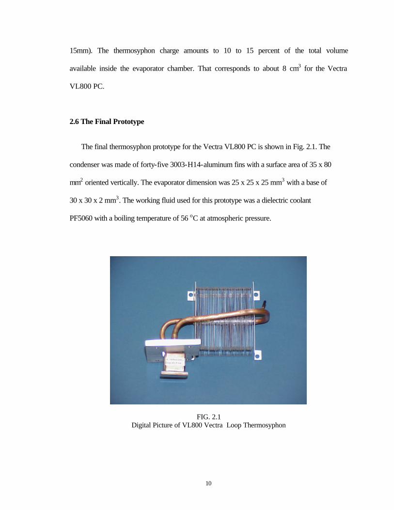
This prototype was developed to replace the existing thermal management scheme
of a heat sink with an integral fan as shown in Fig. 2.2.
FIG. 2.2 The existing thermal management scheme utilized in the HP Vectra desktop computer.
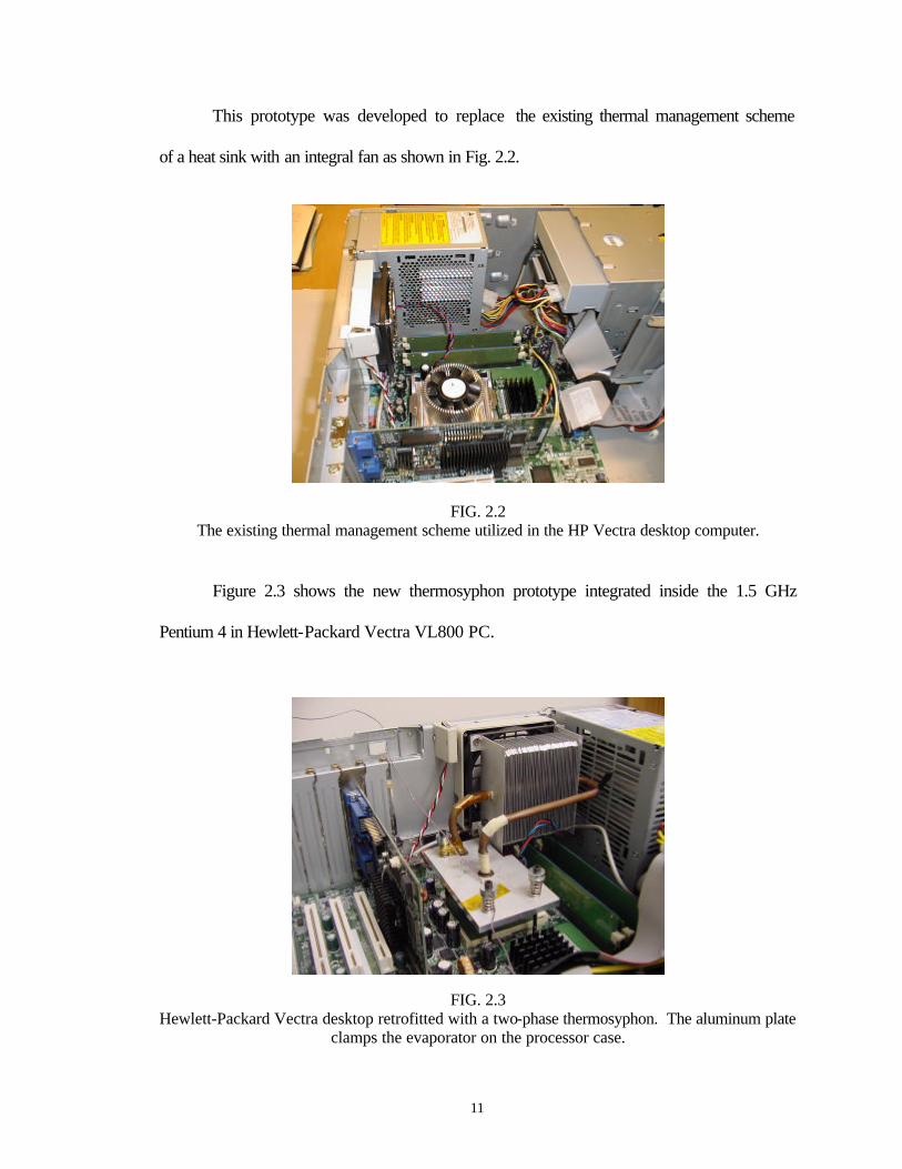
Figure 2.3 shows the new thermosyphon prototype integrated inside the 1.5 GHz
Pentium 4 in Hewlett-Packard Vectra VL800 PC.
FIG. 2.3 Hewlett-Packard Vectra desktop retrofitted with a two-phase thermosyphon. The aluminum plate
clamps the evaporator on the processor case.
12
CHAPTER 3 INVESTIGATION ON THE PERFORMANCE OF THE LOOP
THERMOSYPHON
3.1 Inclination Effects
The performance of loop thermosyphon demonstration vehicle as a function of tilting
angle was examined. Experiments were performed using a HP custom design protractor
assembly to tilt the loop thermosyphon under a controlled condition. The tests were
performed at a constant heat dissipation of 60 Watts for different tilting angles at an
increment of 2o in both positive and negative direction from the horizontal position of the
loop thermosyphon system.
3.1.1 Experimental Method and Apparatus
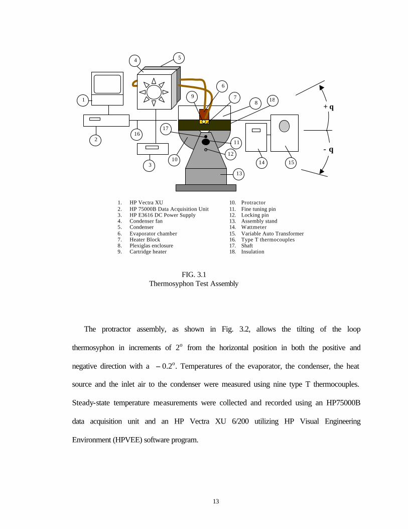
A schematic of the experimental apparatus is shown in Fig. 3.1. The evaporator
chamber is attached to the top surface of a copper heater block. The bottom surface of the
evaporator chamber is attached to the top surface of the heater block with thermal
compound interface material (thermal conductivity = 0.39 W/(m-K)). Both the evaporator
chamber and the heater block assembly are centered inside a bolted Plexiglas/Ultem
enclosure to ensure a firm attachment between the evaporator and the surface of the heat
source to minimize the interface resistance and to reduce heat lose to the environment.
The heat source dimension is 30 x 30 x 10 mm3. A cartridge heater inserted into the
cooper block to provide 60 Watts of total power. The heat is provided by a variable
power supply monitored by a digital wattmeter. The condenser is cooled by a fan
powered by an HP E3616A DC power supply.
13
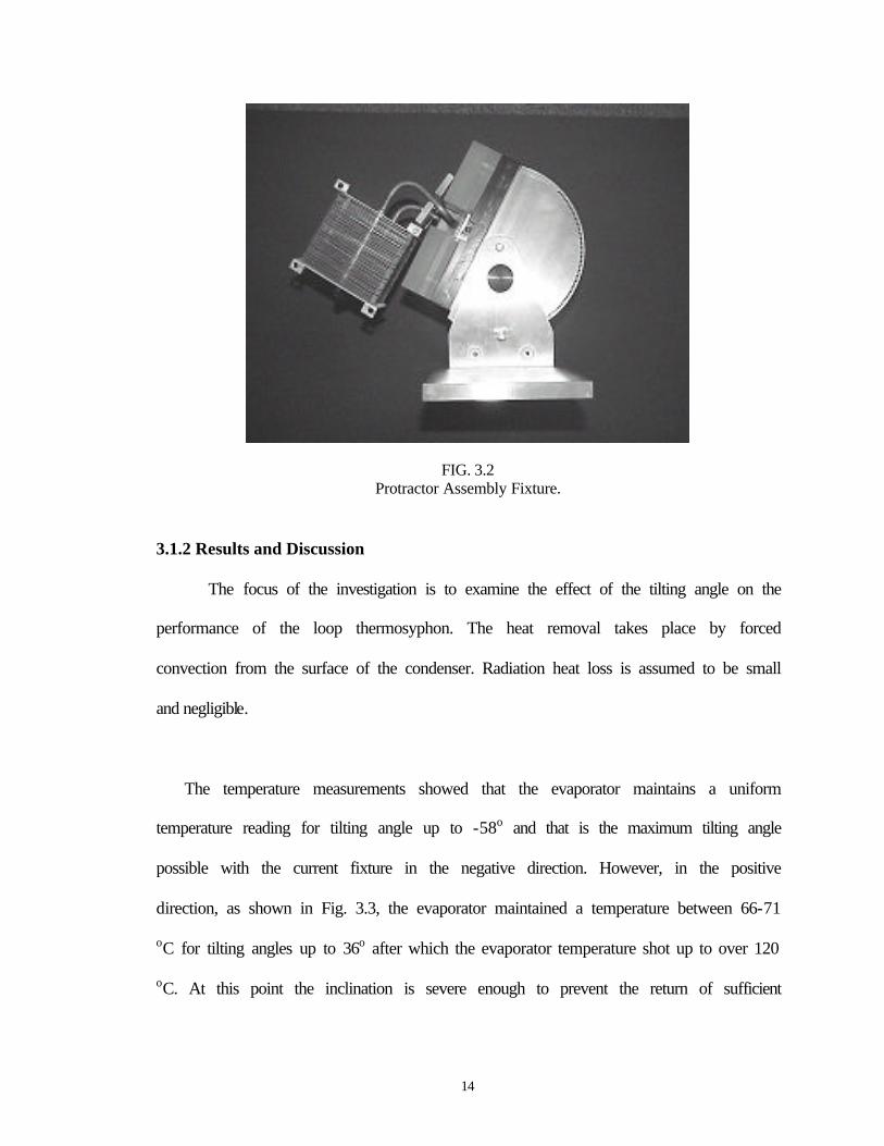
The protractor assembly, as shown in Fig. 3.2, allows the tilting of the loop
thermosyphon in increments of 2o from the horizontal position in both the positive and
negative direction with a ± 0.2o. Temperatures of the evaporator, the condenser, the heat
source and the inlet air to the condenser were measured using nine type T thermocouples.
Steady-state temperature measurements were collected and recorded using an HP75000B
data acquisition unit and an HP Vectra XU 6/200 utilizing HP Visual Engineering
Environment (HPVEE) software program.
1
2
3
5 4
11
12
15 10
8
14
6
7
17
13
16
1. HP Vectra XU 2. HP 75000B Data Acquisition Unit 3. HP E3616 DC Power Supply 4. Condenser fan 5. Condenser 6. Evaporator chamber 7. Heater Block 8. Plexiglas enclosure 9. Cartridge heater
FIG. 3.1 Thermosyphon Test Assembly
θ+
θ−
918
10. Protractor 11. Fine tuning pin 12. Locking pin 13. Assembly stand 14. Wattmeter 15. Variable Auto Transformer 16. Type T thermocouples 17. Shaft 18. Insulation
14
FIG. 3.2 Protractor Assembly Fixture.
3.1.2 Results and Discussion
The focus of the investigation is to examine the effect of the tilting angle on the
performance of the loop thermosyphon. The heat removal takes place by forced
convection from the surface of the condenser. Radiation heat loss is assumed to be small
and negligible.
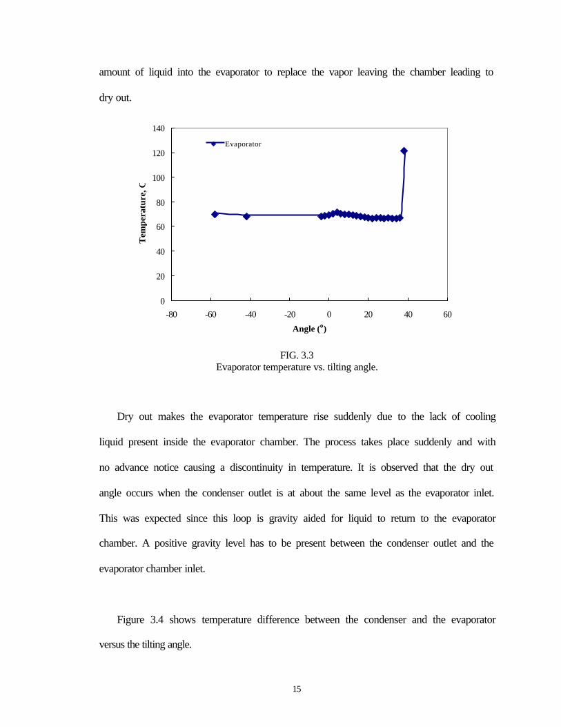
The temperature measurements showed that the evaporator maintains a uniform
temperature reading for tilting angle up to -58o and that is the maximum tilting angle
possible with the current fixture in the negative direction. However, in the positive
direction, as shown in Fig. 3.3, the evaporator maintained a temperature between 66-71
oC for tilting angles up to 36o after which the evaporator temperature shot up to over 120
oC. At this point the inclination is severe enough to prevent the return of sufficient
15
amount of liquid into the evaporator to replace the vapor leaving the chamber leading to
dry out.
0
20
40
60
80
100
120
140
-80 -60 -40 -20 0 20 40 60
Angle (o)
Tem
pera
ture
, CEvaporator
FIG. 3.3 Evaporator temperature vs. tilting angle.
Dry out makes the evaporator temperature rise suddenly due to the lack of cooling
liquid present inside the evaporator chamber. The process takes place suddenly and with
no advance notice causing a discontinuity in temperature. It is observed that the dry out
angle occurs when the condenser outlet is at about the same level as the evaporator inlet.
This was expected since this loop is gravity aided for liquid to return to the evaporator
chamber. A positive gravity level has to be present between the condenser outlet and the
evaporator chamber inlet.
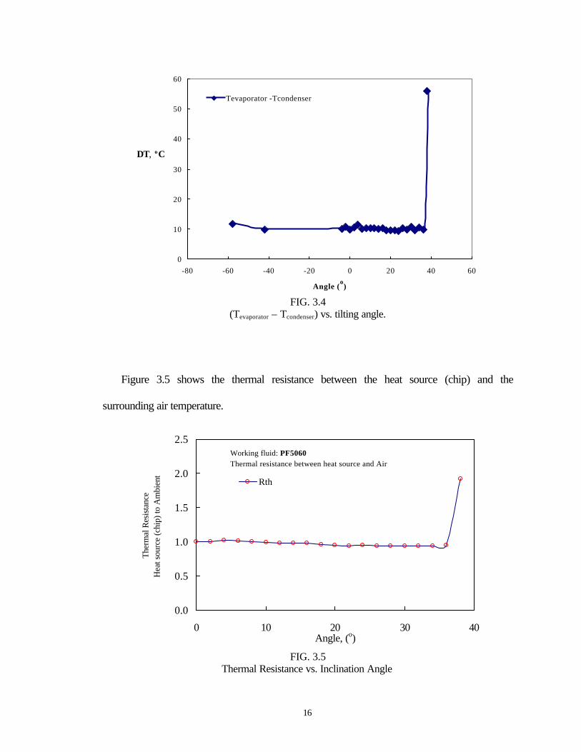
Figure 3.4 shows temperature difference between the condenser and the evaporator
versus the tilting angle.
16
0
10
20
30
40
50
60
-80 -60 -40 -20 0 20 40 60
Angle (o)
Tevaporator -Tcondenser
C T o,∆
FIG. 3.4
(Tevaporator – Tcondenser) vs. tilting angle.
Figure 3.5 shows the thermal resistance between the heat source (chip) and the
surrounding air temperature.
0.0
0.5
1.0
1.5
2.0
2.5
0 10 20 30 40Angle, (o)
Ther
mal
Res
ista
nce
Hea
t sou
rce
(chi
p) to
Am
bien
t
Rth
Working fluid: PF5060Thermal resistance between heat source and Air
FIG. 3.5
Thermal Resistance vs. Inclination Angle
17
The thermal resistance maintains a constant value up until reaching dry out
temperature where the thermal resistance jumps to close the value of 2. A key finding is
the thermal performance of the loop thermosyphon remained almost unaltered for a very
large tilting angle. The results in this report represent preliminary findings and further
testing will be performed on the general performance of the loop thermosyphon using
water at a reduced pressure as the working fluid.
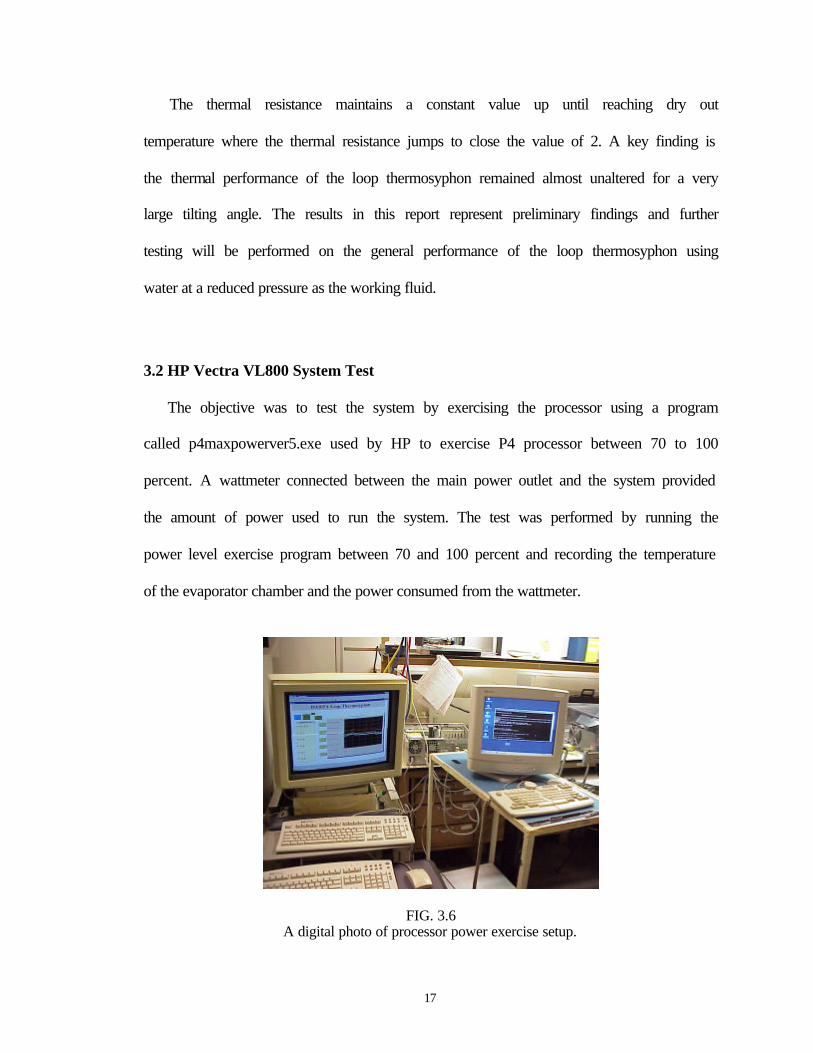
3.2 HP Vectra VL800 System Test
The objective was to test the system by exercising the processor using a program
called p4maxpowerver5.exe used by HP to exercise P4 processor between 70 to 100
percent. A wattmeter connected between the main power outlet and the system provided
the amount of power used to run the system. The test was performed by running the
power level exercise program between 70 and 100 percent and recording the temperature
of the evaporator chamber and the power consumed from the wattmeter.
FIG. 3.6 A digital photo of processor power exercise setup.
18
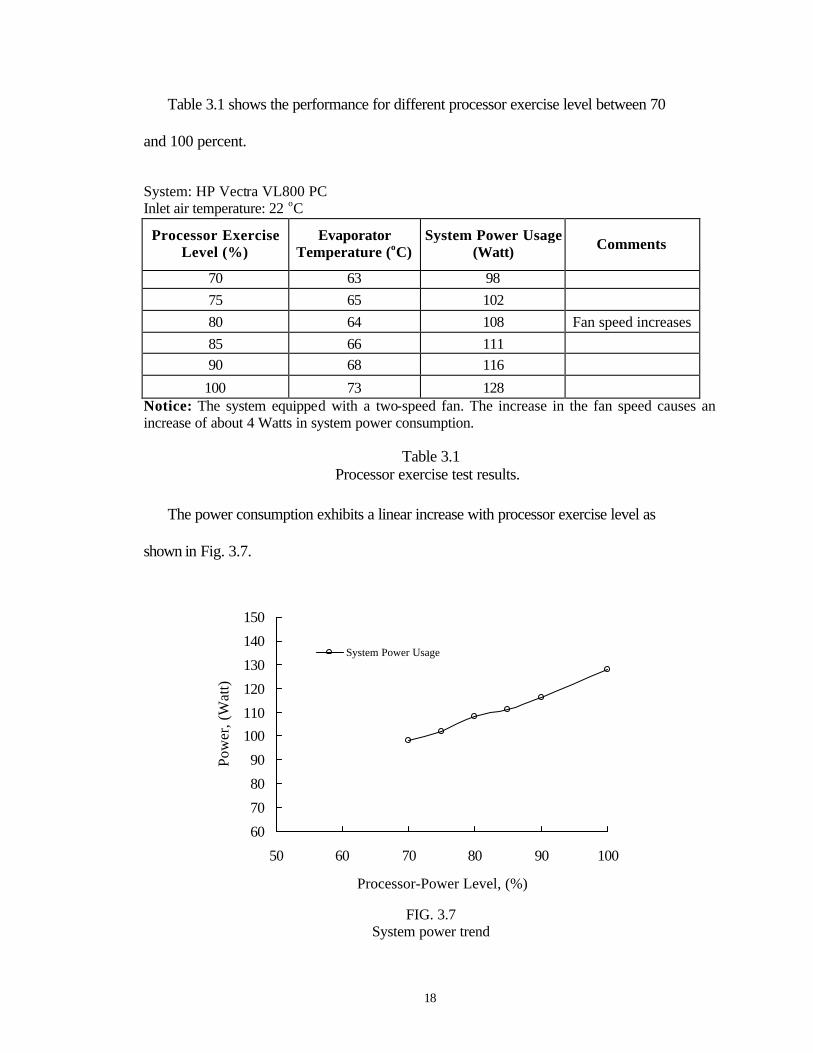
Table 3.1 shows the performance for different processor exercise level between 70
and 100 percent.
System: HP Vectra VL800 PC Inlet air temperature: 22 oC
Processor Exercise Level (%)
Evaporator Temperature (oC)
System Power Usage (Watt) Comments
70 63 98 75 65 102 80 64 108 Fan speed increases 85 66 111 90 68 116
100 73 128 Notice: The system equipped with a two-speed fan. The increase in the fan speed causes an increase of about 4 Watts in system power consumption.
Table 3.1 Processor exercise test results.
The power consumption exhibits a linear increase with processor exercise level as
shown in Fig. 3.7.
60
70
80
90
100
110
120
130
140
150
50 60 70 80 90 100
Processor-Power Level, (%)
Pow
er, (
Wat
t)
System Power Usage
FIG. 3.7
System power trend
19
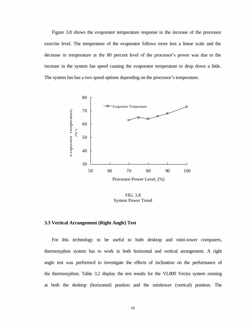
Figure 3.8 shows the evaporator temperature response to the increase of the processor
exercise level. The temperature of the evaporator follows more less a linear scale and the
decrease in temperature at the 80 percent level of the processor’s power was due to the
increase in the system fan speed causing the evaporator temperature to drop down a little.
The system fan has a two speed options depending on the processor’s temperature.
30
40
50
60
70
80
50 60 70 80 90 100
Processor-Power Level, (%)
Evaporator Temperature
Eva
pora
tor T
empe
ratu
re,
(o C)
FIG. 3.8 System Power Trend
3.3 Vertical Arrangement (Right Angle) Test
For this technology to be useful to both desktop and mini-tower computers,
thermosyphon system has to work in both horizontal and vertical arrangement. A right
angle test was performed to investigate the effects of inclination on the performance of
the thermosyphon. Table 3.2 display the test results for the VL800 Vectra system running
at both the desktop (horizontal) position and the minitower (vertical) position. The
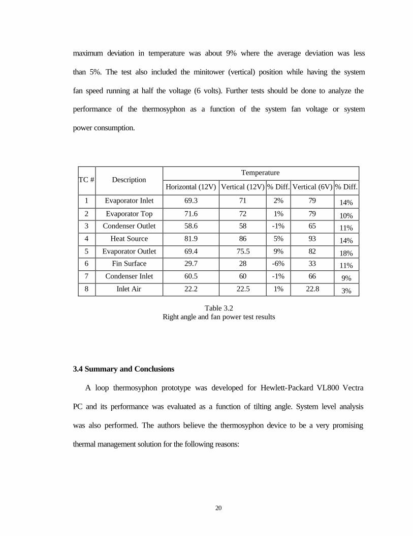
20
maximum deviation in temperature was about 9% where the average deviation was less
than 5%. The test also included the minitower (vertical) position while having the system
fan speed running at half the voltage (6 volts). Further tests should be done to analyze the
performance of the thermosyphon as a function of the system fan voltage or system
power consumption.
Temperature TC # Description
Horizontal (12V) Vertical (12V) % Diff. Vertical (6V) % Diff.
1 Evaporator Inlet 69.3 71 2% 79 14% 2 Evaporator Top 71.6 72 1% 79 10% 3 Condenser Outlet 58.6 58 -1% 65 11% 4 Heat Source 81.9 86 5% 93 14% 5 Evaporator Outlet 69.4 75.5 9% 82 18% 6 Fin Surface 29.7 28 -6% 33 11% 7 Condenser Inlet 60.5 60 -1% 66 9% 8 Inlet Air 22.2 22.5 1% 22.8 3%
Table 3.2
Right angle and fan power test results
3.4 Summary and Conclusions
A loop thermosyphon prototype was developed for Hewlett-Packard VL800 Vectra
PC and its performance was evaluated as a function of tilting angle. System level analysis
was also performed. The authors believe the thermosyphon device to be a very promising
thermal management solution for the following reasons:
21
1. Thermosyphon is a passive heat transfer device that has no mechanical parts,
which significantly reduces its reliability issues.
2. No energy is added to circulate the fluid and transfer the heat to the condenser by
virtue of a pump.
3. It has a high heat removal capacity.
4. It has flexibility in design and integration.
5. Its quiet operation, in addition to the reduction in noise by replacing the heat sink
fan, is a positive step for consumer and office desktop systems.
6. Eliminates preheated air generated inside the system by processor’s heat sink
since heat removed from the processor gets transferred to the condenser and into
the air leaving the computer system.
7. Cost of producing large quantities for the VL800 PC is estimated to match that of
the existing thermal management solution (fan mounted heat sink).
Acknowledgement
The authors would like to acknowledge Professor Yogendra Joshi of Georgia Tech.,
Cullen Bash of HP Labs and Todd Wenger of Thermacore Inc. for their assistance with
this project.
22
REFERENCES
1. Garner, S.D. & Patel, C.D., “Loop Thermosyphons and Their Applications to High density Electronics Cooling,” Proceedings of the International Electronic Packaging Technical Conference and Exhibition, 2001. 2. Pal, A., Joshi, Y., Beitelmal, A. H., Patel, C. D. and Wenger, T., “Design and Performance Evaluation of a Compact Thermosyphon,” Proceedings of the United Engineering Foundation, Thermes, Santa Fe, New Mexico, January 2002. 3. DARPA Heretic program website (http://www.darpa.mil/mto/heretic/).