the re-commissioned thermosyphon reboiler research ... · pdf filethe re-commissioned...
TRANSCRIPT
The re-commissioned thermosyphon reboiler research facility in the Morton Laboratory
A. Alane & P. J. Heggs School of Chemical Engineering and Analytical Science, The University of Manchester, UK
Abstract
Vapour generation through boiling is one of the most ubiquitous industrial processes. Vertical thermosyphon reboilers are frequently used to generate vapour at the base of distillation columns. Present design methods have the major emphasis on the process side (boiling). The heating of the vertical boiler is decoupled from the system. Additionally, most academic research has considered a single tube flow arrangement with controlled and uniform electrical heating. However, many applications in distillation are now using sub-atmospheric pressure operation (higher thermodynamic efficiency, reduced energy consumption, prevents thermal degradation, cheaper materials of construction and safe operation). The literature does not contain many references to this mode of operation and existing design techniques do no adequately cover sub-atmospheric pressure operation. The thermosyphon reboiler research facility at the University of Manchester in the Morton Laboratory comprises 50 tubes of 3 m thermal lengths (19.86 mm ID) and 3 segmental baffles (TEMA E type shell and TEMA A type header) with steam condensing on the shell side, 2 large horizontal condensers with 106 and 196 tubes, both TEMA E type shells and B type headers. Vacuum is pulled on the process side and the shell side by means of two separate liquid ring pumps. The process fluid is water flowing in the tubes counter-current to the condensing steam in the shell side. The primary objective is to study the operation of the thermosyphon reboiler over the pressure range 0.1 bar – atmospheric. New additional instrumentation for temperature, pressure and flow measurements have been calibrated and installed. At the present time, the equipment is fully instrumented, re-insulated and has been successfully commissioned. This paper describes the equipment in detail, its configuration, instrumentation (control, safety and scientific), modifications from the previous arrangement (Emerson DeltaV computer control software and data logger, new instrumentation) and the effect on errors in the mass and energy calculations. A brief reference will be made to the complications encountered during commissioning and the solutions adopted. Keywords: boiling, vacuum, thermosyphon reboiler, research facility, coupled problem, instrumentation, commissioning.
Advanced Computational Methods in Heat Transfer IX 337
© 2006 WIT PressWIT Transactions on Engineering Sciences, Vol 53, www.witpress.com, ISSN 1743-3533 (on-line) doi:10.2495/HT060331

1 Introduction
Of all reboiler types, thermosyphon reboilers are the most commonly used in the chemical industry Arneth and Stichlmair [1]. These heat transfer units are characterised by high heat transfer rates and relatively low fouling tendencies. The residence times tend to be reduced in thermosyphon reboilers, which minimises the risk of thermal degradation. Thermosyphon reboilers are regarded as reliable means of heat input and removal into and from industrial processes when used in their proper range of operation. These type of reboilers are highly efficient as they combine high heat transfer rates and low capital and operating costs. They have no moving parts that require maintenance or mechanical seals prone to leaks. When they are designed properly they can be used in a wide range of process conditions, that is temperatures, pressures, flow and heat loads Sloley [2]. However, lack of experimental data and robust design methods deterred many plants, and in some instances entire industries to avoid their usage. It is important therefore to understand both the steady state design of the system and its potential dynamic behaviour, and the interactions between fluid dynamics and heat transfer Sloley [2]. The prediction of the heat transfer and the thermally-induced circulation rates are the primary requirements for the successful designs. Ali and Alam[3] and Kamil et al. [4] used different fluids (acetone and ethylene glycol, distilled water, methanol, benzene, toluene and ethylene glycol respectively) to demonstrate the effects of heat flux and submergence on circulation rates in a single vertical tube thermosyphon reboiler, which was heated electrically and also developed empirical correlations. The circulation of fluid through the thermosyphon is established by the differential head, which exists between the cold and hot legs of the loop. The hydrostatic head in the cold leg (down-flow from disengagement tank or returning fluid) depends upon the liquid submergence, which can have a maximum value that corresponds usually to the top tube sheet or the top end of the test section. This is referred to as 100% submergence and corresponds to conditions at the bottom of a distillation column. Kamil et al. [4] considered other submergence levels (notably, 75%, 50% and 30%). The hydrostatic head in the hot leg (reboiler leg) was provided by the process fluid, which consists of a two-phase mixture, the quality of which changes with boiling and vapour generation as the fluid flows upwards in the heated channel. This generates the buoyancy forces to drive the circulation of fluid in the loop. Flow boiling systems combine complex interfacial heat and mass transfer behaviour in addition to the complexities associated with turbulent two-phase flow. The design of reboilers must take account of the fact that regardless of the temperature of the heating medium, the maximum heat flux is limited by the hydrodynamics of the boiling process. In recent years there has been a growing interest in systems operating at reduced pressures and many applications in distillation are now using sub-atmospheric pressure operation which provides higher thermodynamic efficiency, reduced energy consumption, safe operation,
338 Advanced Computational Methods in Heat Transfer IX
© 2006 WIT PressWIT Transactions on Engineering Sciences, Vol 53, www.witpress.com, ISSN 1743-3533 (on-line)

prevents thermal degradation and enables the use of cheaper materials of construction. Literature on boiling has concentrated on pressures above atmospheric rising to high pressures encountered in modern steam raising plants. Boiling at sub-atmospheric pressure is one that lacks systematic data. In addition, it is not possible to extrapolate methodologies developed to describe high pressure boiling due to the following factors that make the system unique Webb et al. [5]:
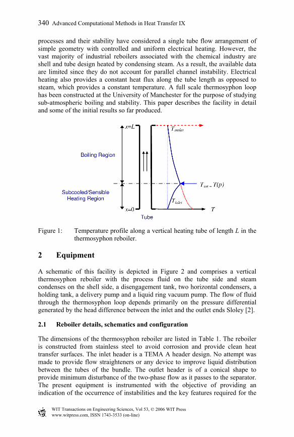
At vacuum, dissolved gases in potential boiling nucleation sites are desorbed, which results in delayed nucleation and unsteady or even no operation. In the case of fixed outlet pressure of the boiling system, the pressure at the entrance to the boiling channel could be several times higher. This difference is due to the static head modified by the pressure drops due to friction and acceleration along the boiling channel. This implies that it is no longer possible to assume constant thermo-physical properties and the saturation temperature may vary significantly along the channel, which affects the boiling process (Figure 1). At sub-atmospheric pressures, pressure fluctuations have a greater impact on the boiling temperature of the circulated liquid. An increase of pressure of 0.1 bar is only 10% increase at atmospheric pressure, though at 0.1 bar this same change is a 100% Moore et al. [6]. As a result, the ratio of the static pressure head to the total pressure at the bottom of the liquid phase increases by decreasing the process pressure. This increases the effect of pressure fluctuations and results in a larger area required for sensible heating, which can be up to 90% of the total length of the tubes (Figure 1). This leads to a drop in the overall heat transfer coefficient. Sub-atmospheric boiling systems are especially prone to instabilities as a result of high vapour velocities and more profound impact of pressure fluctuations. This instability can be a whole-loop type, whereby all the tubes undergo the same fluctuating behaviour, or a parallel-channel type, where the behaviour is not uniform across the bundle. In either case the fluctuating pressure and flow may severely hinder the performance of the plant. In addition, excessive fluctuations in the tubes may lead to periodic dryout at the top tube surface, which may result in the deposition of dissolved materials, excessive fouling and operation failure. High wall superheats are required to initiate and sustain nucleate boiling at low pressure. High pressure drops in the high velocity two-phase boiling region causes the velocity at the entrance of heating channel to be lower. This reduces the overall heat transfer in the subcooled heating zone and the fraction of heat transfer area used for boiling.
In many industrial examples of thermosyphon reboiler design, recirculation in the thermosyphon loop has not started under the conditions determined in the design. This problem is often solved by an increase in the pressure of the steam, but in modern times, the use process integration, such flexible operational flexibility is hard to obtain. In addition, most of the academic studies on boiling
Advanced Computational Methods in Heat Transfer IX 339
© 2006 WIT PressWIT Transactions on Engineering Sciences, Vol 53, www.witpress.com, ISSN 1743-3533 (on-line)
processes and their stability have considered a single tube flow arrangement of simple geometry with controlled and uniform electrical heating. However, the vast majority of industrial reboilers associated with the chemical industry are shell and tube design heated by condensing steam. As a result, the available data are limited since they do not account for parallel channel instability. Electrical heating also provides a constant heat flux along the tube length as opposed to steam, which provides a constant temperature. A full scale thermosyphon loop has been constructed at the University of Manchester for the purpose of studying sub-atmospheric boiling and stability. This paper describes the facility in detail and some of the initial results so far produced.
Figure 1: Temperature profile along a vertical heating tube of length L in the thermosyphon reboiler.
2 Equipment
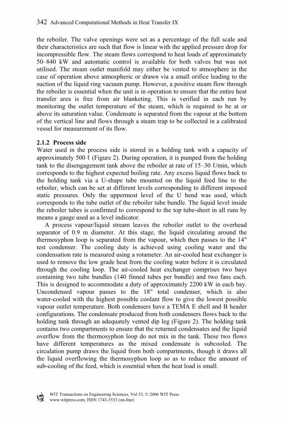
A schematic of this facility is depicted in Figure 2 and comprises a vertical thermosyphon reboiler with the process fluid on the tube side and steam condenses on the shell side, a disengagement tank, two horizontal condensers, a holding tank, a delivery pump and a liquid ring vacuum pump. The flow of fluid through the thermosyphon loop depends primarily on the pressure differential generated by the head difference between the inlet and the outlet ends Sloley [2].
2.1 Reboiler details, schematics and configuration
The dimensions of the thermosyphon reboiler are listed in Table 1. The reboiler is constructed from stainless steel to avoid corrosion and provide clean heat transfer surfaces. The inlet header is a TEMA A header design. No attempt was made to provide flow straighteners or any device to improve liquid distribution between the tubes of the bundle. The outlet header is of a conical shape to provide minimum disturbance of the two-phase flow as it passes to the separator. The present equipment is instrumented with the objective of providing an indication of the occurrence of instabilities and the key features required for the
340 Advanced Computational Methods in Heat Transfer IX
© 2006 WIT PressWIT Transactions on Engineering Sciences, Vol 53, www.witpress.com, ISSN 1743-3533 (on-line)

inception of stable operation. Thermocouples are installed at the entrance of a total of 20 tubes at three different depths in the subcooled region. Future work will focus on determining the extent to which flow instabilities might affect performance.
Table 1: Reboiler dimensions.
Shell / Tube / mm / mm Outer diameter, OD 323.80 Tube length 3135 Thickness 4.57 Tube heat transfer length 3063 Inside diameter, ID 314.66 Number of tubes 50 Heat transfer Length 3063 Heat Transfer Areas / m2 Tube pitch (square pitch) 31.75 Inside area per tube 0.191 Tube outer diameter, OD 25.40 Total inside area 9.55 Thickness 2.77 Outside area per tube 0.244 Tube inside diameter, ID 19.86 Total outside area 12.22
V145
E112
V150
V143
P126
E114
VENT
DPT
Cooling Water Supply
Cooling Water Return
Cooling Water Return
Cooling Water Supply
wfmwfT
wrmwrT
0sm
iT0
oT0
0Q
1cm 2cm1cT 2cT1sm 1wm1T1Q
2Q1alm
2alm
2am2sm2sT
3am3sm3sT
System 2 System 3
System 1
System 4
0sm
P123
Holding Tank
Disengagement Tank
Test Condenser
Total Condenser
Seal Fluid Tank
Thermosyphon Reboiler
Liquid Ring Pump
Cooler
PCV 103
PCV 200PIC200
PT200
Steam Supply
PIC600
PT600
PCV 600
Inlet Gate Valve
PT103
PIC103
Figure 2: Schematic of the thermosyphon reboiler research facility at the University of Manchester.
2.1.1 Steam supply The process liquid is heated in the tube side of the vertical thermosyphon reboiler by the condensing steam in the shell side. Steam is supplied at 4.5 bar (147.9oC) and passes through a mild steel vessel fitted with knitted wire mess pad to act as a demister to separate the condensate from the steam via a steam trap and stabilise the pressure. The dry steam then passes to the shell of the reboiler via two control valves, the first of which acts to regulate the steam pressure upstream while the second is used to maintain a constant steam flow to
Advanced Computational Methods in Heat Transfer IX 341
© 2006 WIT PressWIT Transactions on Engineering Sciences, Vol 53, www.witpress.com, ISSN 1743-3533 (on-line)
the reboiler. The valve openings were set as a percentage of the full scale and their characteristics are such that flow is linear with the applied pressure drop for incompressible flow. The steam flows correspond to heat loads of approximately 50–840 kW and automatic control is available for both valves but was not utilised. The steam outlet manifold may either be vented to atmosphere in the case of operation above atmospheric or drawn via a small orifice leading to the suction of the liquid ring vacuum pump. However, a positive steam flow through the reboiler is essential when the unit is in operation to ensure that the entire heat transfer area is free from air blanketing. This is verified in each run by monitoring the outlet temperature of the steam, which is required to be at or above its saturation value. Condensate is separated from the vapour at the bottom of the vertical line and flows through a steam trap to be collected in a calibrated vessel for measurement of its flow.
2.1.2 Process side Water used in the process side is stored in a holding tank with a capacity of approximately 500 ℓ (Figure 2). During operation, it is pumped from the holding tank to the disengagement tank above the reboiler at rate of 15–30 ℓ/min, which corresponds to the highest expected boiling rate. Any excess liquid flows back to the holding tank via a U-shape tube mounted on the liquid feed line to the reboiler, which can be set at different levels corresponding to different imposed static pressures. Only the uppermost level of the U bend was used, which corresponds to the tube outlet of the reboiler tube bundle. The liquid level inside the reboiler tubes is confirmed to correspond to the top tube-sheet in all runs by means a gauge used as a level indicator. A process vapour/liquid stream leaves the reboiler outlet to the overhead separator of 0.9 m diameter. At this stage, the liquid circulating around the thermosyphon loop is separated from the vapour, which then passes to the 14″ test condenser. The cooling duty is achieved using cooling water and the condensation rate is measured using a rotameter. An air-cooled heat exchanger is used to remove the low grade heat from the cooling water before it is circulated through the cooling loop. The air-cooled heat exchanger comprises two bays containing two tube bundles (140 finned tubes per bundle) and two fans each. This is designed to accommodate a duty of approximately 2200 kW in each bay. Uncondensed vapour passes to the 18″ total condenser, which is also water-cooled with the highest possible coolant flow to give the lowest possible vapour outlet temperature. Both condensers have a TEMA E shell and B header configurations. The condensate produced from both condensers flows back to the holding tank through an adequately vented dip leg (Figure 2). The holding tank contains two compartments to ensure that the returned condensates and the liquid overflow from the thermosyphon loop do not mix in the tank. These two flows have different temperatures as the mixed condensate is subcooled. The circulation pump draws the liquid from both compartments, though it draws all the liquid overflowing the thermosyphon loop so as to reduce the amount of sub-cooling of the feed, which is essential when the heat load is small.
342 Advanced Computational Methods in Heat Transfer IX
© 2006 WIT PressWIT Transactions on Engineering Sciences, Vol 53, www.witpress.com, ISSN 1743-3533 (on-line)
2.1.3 Vacuum system The reboiler/condenser rig is brought to and maintained at sub-atmospheric pressure by means of two liquid ring pumps and the associated seal fluid circuits. As the rig runs below atmospheric pressure, some gas inevitably leaks into the system, which is drawn into the liquid ring pump before it is expelled together with the seal fluid into the seal fluid tank. The process pressure is adjusted by means of recycle of some of gas to the liquid ring pump through valve PCV 103. The pressure in the system is found to be constant without automatic control action. The liquid ring pump requires a continuous supply of liquid to sustain the sealing liquid ring revolving concentric to the pump casing. This seal liquid is cooled by means of a cooler to remove the heat generated by compression and the latent heat of condensed vapour. The temperature and hence the vapour pressure of the seal liquid should not increase to prevent cavitation. Some problems are likely to occur, however, as a result of direct venting of the reboiler shell steam to the pump.
3 Instrumentation
3.1 Control instrumentation
Control and monitoring of the plant areas as well as data logging is achieved using DeltaV. This control system provides continuous PID control (if automatic control is activated) and is very flexible with respect to the operating characteristics and the setting of alarms and warnings. Three control loops are suggested for the operation of the reboiler-condenser rig as it is illustrated in the schematic in Figure 2
3.1.1 Steam pressure regulation This is meant to eliminate fluctuations in the steam supply pressure to the reboiler. The control is achieved using a Camflex regulating valve. A pressure transmitter situated downstream of the valve on the steam line sends an input signal, which upon comparison with the set point, acts on the control valve to maintain the supply pressure at the required value.
3.1.2 Rate of boiling The rate of boiling in the reboiler (steam flow and pressure) can be adjusted and maintained using a second Camflex control valve, which is connected a pressure transmitter on the shell side of the reboiler. A set point is selected for the control loop to establish a temperature difference between the shell and tube sides of the reboiler. Based on the input signal from the transmitter relative to the set point, the control system acts on the control valve to allow more or less flow of steam to the shell side of reboiler.
3.1.3 Process pressure A pressure transmitter is located at the disengagement tank (process side) and is used to monitor the pressure of the process side. The signal it generates is collected by the control system, which is compared to the set point before action
Advanced Computational Methods in Heat Transfer IX 343
© 2006 WIT PressWIT Transactions on Engineering Sciences, Vol 53, www.witpress.com, ISSN 1743-3533 (on-line)
is taken on the third Camflex control valve to allow more or less gas recycle around the liquid ring pump. This in turn acts to change the system pressure as the liquid ring pump extracts the gas phase at a constant volumetric flow.
3.2 Safety instrumentation
For safe operation, the steam supply can be interrupted in case of an emergency using the emergency shutdown button on the shutdown panel. This panel is designed in-house and is fail-safe to prevent operation in the event of failure of plant services. This implies that the steam supply is suspended automatically upon failure of electrical supply, instrument compressed air and control computer (integrated on the panel). At the highest level of the control parameters (T, P and steam flow), a programmable logic controller (PLC) secures automatic shutdown of the plant. This system works entirely independently of the process control system. The operation of the reboiler-condenser rig will be shut down in any one of the alarm conditions determined by the HAZOP study that was performed on the rig, notably:
High coolant temperature in knockout condenser Low coolant flow to knockout condenser High pressure in process side of the reboiler High temperature of the seal fluid around the liquid ring pump
3.3 Scientific Instrumentation
The pressures are measured using pressure transmitters calibrated over different pressure ranges corresponding to different locations within the facility. Fluid temperatures are measured using constantan-copper T-type thermocouple with a temperature range of −200–400oC and a signal output of –100 to 100 mV. The thermocouples have an outside diameter of 1.50 mm, which gives them a small heat capacity and thus a quick response to temperature changes. Temperatures are measured at 65 locations around the process and cooling system. All the thermocouples have been characterised in DeltaV to account for the deviations obtained during their calibration. The flow of the cooling water is measured by means of orifice plates designed in accordance to the criteria and limits specified in BS1042, the pressure drop across which is measured using strain gauge DP cells, which produce signals in the range of 4–20 mA. Flows around the process side are measured at different locations using rotameters, which will be replaced soon by electromagnetic flow meters. An additional DP cells is fitted across the inlet gate valve to the reboiler bottom header to obtain a reading of the pressure drop and convert it into the corresponding measurement of flow in the thermosyphon loop. Provision has been included in the apparatus for water to be pumped across the valve so that it can be calibrated against a rotameter. The flow is calculated using eq. (1), which has been obtained from the calibration of the inlet gate valve and describes the relationship that exists between the flow, the number of turns of the valve and the signal output:
( )92.3−= InkV (1)
344 Advanced Computational Methods in Heat Transfer IX
© 2006 WIT PressWIT Transactions on Engineering Sciences, Vol 53, www.witpress.com, ISSN 1743-3533 (on-line)

where V is the volumetric flow in ℓ/min, kn is a constant related to the number of turns by which the valve was opened and I is the current or signal output (mA), where 3.92 mA is the signal output corresponding to no flow. The Bernoulli’s equation is reflected in this expression by the square root dependence of the flow on the signal output. The constant kn responds to a quadratic expression of the number of the gate valve turns, that is:
cbnankn ++= 2 (2) where, n is the number of turns open of the valve and a, b and c are coefficients determined from the different flows and signal outputs using the matrix method to solve multivariate sets of equations or the Solver option in Excel. Throughout tests that were conducted to check the reliability of eqs. (1) and (2), a maximum deviation of ±6.50% was obtained between the calculated flow and that obtained from the rotameter. The calibration equation is different from the one obtained from the previous configuration Webb et al. [7].
3.4 DeltaV control and data logging software
The analogue signals from the measuring devices (mV from thermocouples and mA from pressure transmitters) are conditioned in the control panels in the laboratory. These signals are then digitised using Emerson 8 CH, TI blocks for the thermocouples and Emerson AI, 8CH, 4-20 mA for the pressure transmitters and DP cells. These are analogue-to-digital converter cards located in the control panels. The resultant digital signals are then sent through data cables to the computers where they are characterised and converted into numerical readings using the DeltaV control software. The DeltaV system is also used as a data logger, whereby the data is continuously recorded using Historian and logged into an Excel spreadsheet. Alternatively, the data can be continuously recorded using a Macro created to export the data from DeltaV. In both options, readings are taken at regular time steps, which are selected to the requirements of the user.
4 Planned experiments
Theses are water tests at low pressure. The first set of tests on the rig would establish the limits of operability, which would be followed by detailed performance tests over the range of operability. This involves taking measurements of the overall heat transfer coefficients, circulation rates, pressure drops across the circuit and fluid temperatures. It is intended that these investigative studies would cover both steady state and unstable operation and the work will be validated through mass and energy balances. This work will be carried out over a range of system pressures at and below atmospheric (0.1 bar– atmospheric). The range of operation will be defined by the imposed temperature difference at each pressure and the corresponding saturation temperature. This implies that a minimum temperature difference exists to promote stable recirculation in the thermosyphon loop and an upper limit of the imposed temperature difference will be defined by either the available steam pressure corresponding to 125oC, the available heat load upper limit, which is estimated at
Advanced Computational Methods in Heat Transfer IX 345
© 2006 WIT PressWIT Transactions on Engineering Sciences, Vol 53, www.witpress.com, ISSN 1743-3533 (on-line)
about 820 kW or simply by some form of instability. In the case when unstable operation is the limiting factor, throttling the flow into the reboiler should be considered Webb et al. [5] and Moore et al. [6]. The thermocouples are inserted at three different depths in 20 of the reboiler tubes and should provide some indication of the nature of instability through the observed variations of the flow as indicated by the readings from these thermocouples and the pressure transmitters. The depths of insertion of the thermocouples in the tubes were estimated from the expected lengths of the subcooled region over the pressure range of interest.
5 Problems during commissioning
During the early stages of commissioning, the temperature of the seal fluid in the liquid ring vacuum pump on the process side increased considerably, even though it was circulated around a secondary cooler, see Figure 2. The tubes of the cooler were found to be very fouled and almost blocked. The problem was resolved by cleaning using mechanical means. The seal fluid feed line to the pump was fitted with a strainer to ensure that any residual solids were contained. Samples taken from the closed cooling water loop indicated the presence of solid impurities of sizes up to 240 microns, which is likely to foul the two condensers and reduce their thermal efficiencies. The cooling water was treated with sodium nitrite (NaNO2) to neutralise the oxygen present in the cooling water lines and reduce oxidation, which is at the origin of the solid impurities. A filter which is fitted with a 125 micron mesh was also used to filter the cooling water.
6 Initial results
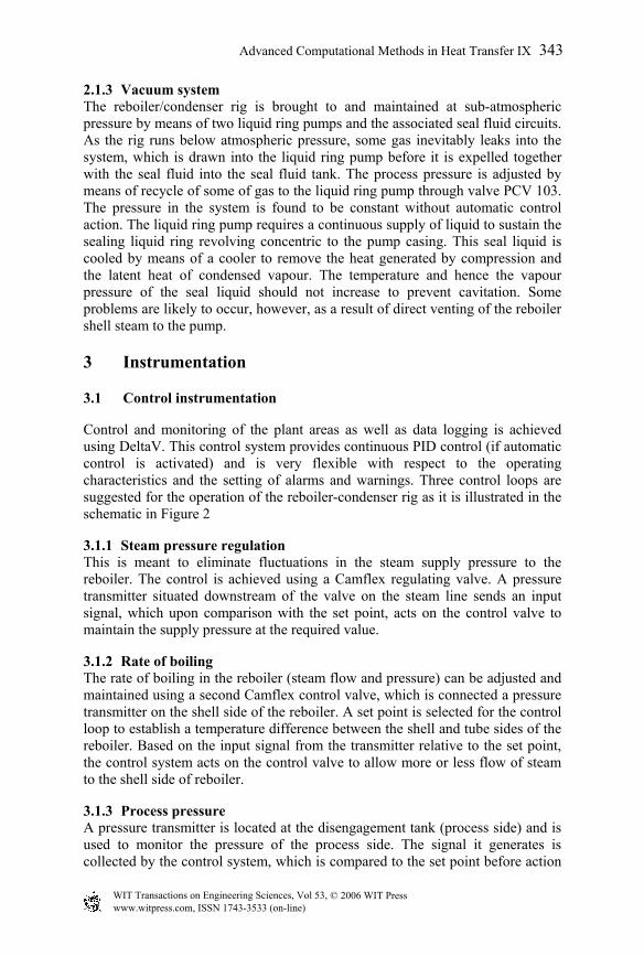
In order to assess the reliability of the measurements, a statistical analysis using linear regression was conducted on the results obtained from the calibration of the inlet gate valve. The flow registered on the variable area flow meter (rotameter) was considered as a function of the flow calculated using eq. (1). Figure 3 depicts the data points and the extrapolation of the regression line to the range of operation with 95% confidence intervals drawn about the regression line. The experimental system is operated under vacuum and so air can leak into the process through the numerous joints and flanges. It is important to quantify the air leakage rate and a method is devised for that purpose. The graph depicted in Figure 4 is a plot of the square root of the manometer height difference and the corresponding air flow. A liquid ring pump connected at the end of the process line pulls the vacuum within the system and so the quantified leakage rate would be for the entire process. The leakage rate was quantified daily using a nozzle box with orifices for different air flows installed in the process line. The entire system is evacuated and all the orifices on the nozzle box were closed. The air is then forced to flow through a vent line. The pressure drop across the vent line was measured using a water manometer and flow of air was varied through a combination of 5, 10, 20
346 Advanced Computational Methods in Heat Transfer IX
© 2006 WIT PressWIT Transactions on Engineering Sciences, Vol 53, www.witpress.com, ISSN 1743-3533 (on-line)

and 40 lb/h orifices. The negative offset shown in Figure 4 represents the leakage rate of air into the entire process. The research facility is located within a glass-walled laboratory and so it is the atmospheric and process pressures that are driving the leakage rate. A typical air leakage plot obtained for the first day of tests is depicted in Figure 4, where the leakage rate was 0.78 kg/h (offset of 1.73 lb/h) compared to the 2.5 kg/h air leakage rate obtained from the previous work Webb et al. [7].
0
75
150
225
300
375
450
525
600
675
0 60 120 180 240 300 360 420 480 540 600 660
x = flowrate / l/min
y =
a.x
+ b
/ l/m
in
Regressiony-y+Actual Data
a & b obtained by means of linear regression Figure 3: Regression line for the circulation loop with 95% confidence
intervals.
y = 0.2635x + 0.4554R2 = 0.9919
0
1
2
3
4
5
6
7
8
-3 0 3 6 9 12 15 18 21 24 27Air Flow / lb/h
(∆h )
1/2 Air Leakage Rate
Linear (Air Leakage Rate)
Offset = leakage rate
Figure 4: Air leakage test on reboiler-condenser rig on 01-02-2006.
Advanced Computational Methods in Heat Transfer IX 347
© 2006 WIT PressWIT Transactions on Engineering Sciences, Vol 53, www.witpress.com, ISSN 1743-3533 (on-line)

6.1 Consistency checks
6.1.1 Vapour generation Individual calculations were carried out on the reboiler and the main condenser to evaluate the rate of vapour generation independently and obtain a basis for comparison as depicted in Figure 5. The graph in Figure 5 indicates that the early tests produced an experimental reliability of around ±20% with respect the flows of vapour from the reboiler and the condenser. In these calculations heat losses have been neglected as the equipment is very well insulated. Previous work by Webb et al. [7] indicated that a permanent condensation rate of around 4 kW was obtained from the main 14″ condenser. However, when compared to heat loads in the experimental work (predominantly above 100 kW) this loss lies within the reliability limits in Figure 5. Later tests have produced lower discrepancies typically within ±5%.
0
2
4
6
8
10
12
14
16
18
20
22
24
26
0 2 4 6 8 10 12 14 16 18 20 22 24 26
Produced vapour from reboiler / kg/min
Prod
uced
vap
our c
onde
nser
/ kg
/min
Experimental Databi-section-20%-10%+10%+20%
Figure 5: Comparison of produced vapour rate.
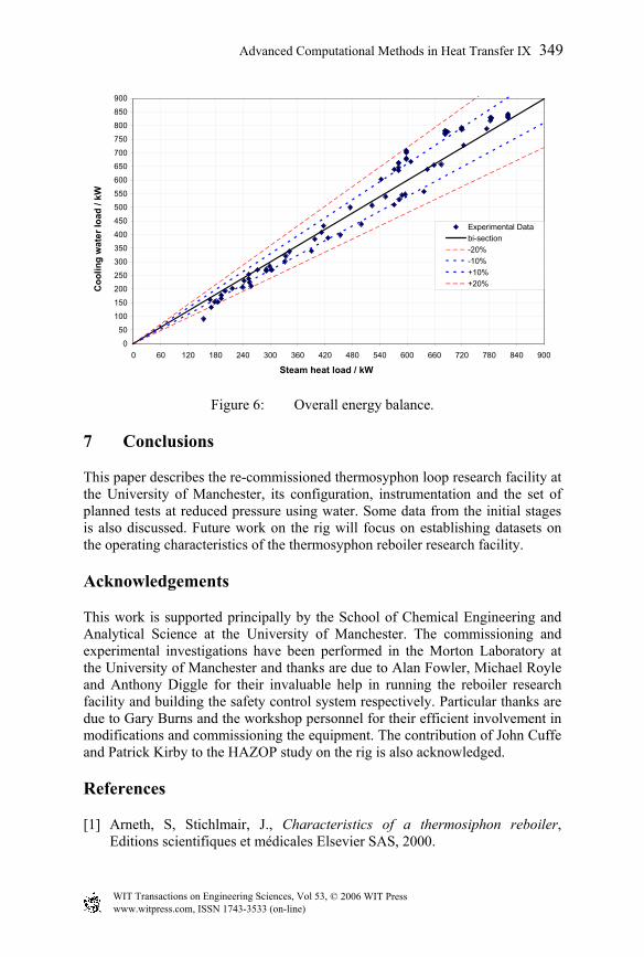
6.1.2 Overall heat load The overall control volume (system 4 in Figure 2) is used to check the overall energy balance (Figure 6). This check is expected to be less reliable since sections of the holding tanks are not insulated. The check is a simple comparison of the enthalpy supplied in kW by the condensed steam ( 0Q ) with the heat gain of the cooling water from the two condensers, that is 21 QQ + . The obtained data are depicted in Figure 6, which indicates that the heat losses are predominantly within ±20%. Analogous to the mass balance, the later tests produced maximum discrepancies within ±5%.
348 Advanced Computational Methods in Heat Transfer IX
© 2006 WIT PressWIT Transactions on Engineering Sciences, Vol 53, www.witpress.com, ISSN 1743-3533 (on-line)
0
50
100
150
200
250
300
350
400
450
500
550
600
650
700
750
800
850
900
0 60 120 180 240 300 360 420 480 540 600 660 720 780 840 900
Steam heat load / kW
Coo
ling
wat
er lo
ad /
kW
Experimental Databi-section-20%-10%+10%+20%
Figure 6: Overall energy balance.
7 Conclusions
This paper describes the re-commissioned thermosyphon loop research facility at the University of Manchester, its configuration, instrumentation and the set of planned tests at reduced pressure using water. Some data from the initial stages is also discussed. Future work on the rig will focus on establishing datasets on the operating characteristics of the thermosyphon reboiler research facility.
Acknowledgements
This work is supported principally by the School of Chemical Engineering and Analytical Science at the University of Manchester. The commissioning and experimental investigations have been performed in the Morton Laboratory at the University of Manchester and thanks are due to Alan Fowler, Michael Royle and Anthony Diggle for their invaluable help in running the reboiler research facility and building the safety control system respectively. Particular thanks are due to Gary Burns and the workshop personnel for their efficient involvement in modifications and commissioning the equipment. The contribution of John Cuffe and Patrick Kirby to the HAZOP study on the rig is also acknowledged.
References
[1] Arneth, S, Stichlmair, J., Characteristics of a thermosiphon reboiler, Editions scientifiques et médicales Elsevier SAS, 2000.
Advanced Computational Methods in Heat Transfer IX 349
© 2006 WIT PressWIT Transactions on Engineering Sciences, Vol 53, www.witpress.com, ISSN 1743-3533 (on-line)

[2] Sloley, A. W., Properly Design Thermosyphon Reboilers, pp. 52–64, Chemical Engineering Progress, 1997.
[3] Ali, H., Alam, S. S., Circulation Rates in Thermosiphon Reboiler, International Journal of Heat and Fluid Flow, Vol.13, pp. 86-92, 1992.
[4] Kamil, M., Alam, S. S., Ali, H., Prediction of Circulation Rates in Vertical Tube Thermosiphon Reboiler, International Journal of Heat Mass Transfer, Vol.38, pp. 745-748, 1993.
[5] Webb, D. R, Benson, H, Heggs, P. J., The new thermosyphon reboiler at UMIST, HTFS Research Symposium, paper RS 1108, 2001.
[6] Moore, M. J. C, Keys, M. H, Plumb, G.R., Design of vertical thermosyphon reboilers for operation under vacuum conditions application in nuclear fuel reprocessing. In: 2nd UK National Heat Transfer Conference, Vol. 2, pp. 1157 – 1169, Glasgow, UK, 1988.
[7] Webb, D. R, Benson, H, Heggs, P. J., Ooi, H., Schnabel, T., Cottrell, C., The UMIST Dataset on Operation of Vertical Thermosiphon Reboilers at Sub-atmospheric Pressures, HTFS Research Symposium, paper RS 1113, 2002.
350 Advanced Computational Methods in Heat Transfer IX
© 2006 WIT PressWIT Transactions on Engineering Sciences, Vol 53, www.witpress.com, ISSN 1743-3533 (on-line)