tutorial on single-pole tripping and reclosing · 1 tutorial on single-pole tripping and reclosing...
TRANSCRIPT
Tutorial on Single-Pole Tripping and Reclosing
Elizabeth Godoy and Alberto Celaya Comisión Federal de Electricidad
Héctor J. Altuve, Normann Fischer, and Armando Guzmán Schweitzer Engineering Laboratories, Inc.
Presented at the 39th Annual Western Protective Relay Conference
Spokane, Washington October 16–18, 2012

1
Tutorial on Single-Pole Tripping and Reclosing Elizabeth Godoy and Alberto Celaya, Comisión Federal de Electricidad
Héctor J. Altuve, Normann Fischer, and Armando Guzmán, Schweitzer Engineering Laboratories, Inc.
Abstract—Power systems are being operated closer to their stability limits, and fewer transmission lines are being built to accommodate the growing demand for power. A fault on a transmission system significantly impacts the power transfer capability of the power system. Taking a line out of service to isolate the fault reduces the power transfer capability, further eroding the stability margin of the power system. Power system faults are predominantly single-phase-to-ground faults and, as such, can be successfully isolated by taking only the faulted phase out of service and keeping the remaining two healthy phases in service. By doing this, the affected power line is still capable of transferring two-thirds of the power and keeping the sources at both line terminals in synchronism.
Single-pole switching (SPS) is the method by which only the faulted phase is taken out of service. SPS does not come without its challenges. From the point of view of a protection engineer, the complexity of the protection scheme is increased. From the point of view of a systems operator, questions need to be addressed, such as: “How long can the system tolerate a single-pole open condition (an unbalance on the system) before it affects generators and motors?” SPS also leads to challenges on the power system, such as the extinction of the secondary arc resulting from the coupling between the faulted phase and healthy phase conductors.
In this paper, we review the benefits afforded by SPS with regard to the robustness and stability of the power system and discuss the challenges issued by SPS to both the power system and the power engineer.
I. INTRODUCTION Single-pole switching (SPS), which is the combination of
single-pole tripping (SPT) and single-pole reclosing (SPR), has been in service in Europe since the 1950s on 155 kV and 220 kV transmission lines [1]. Interestingly enough, at that time, the motivation for using SPS was not to improve power system stability but the power system energy supply to meet the electric energy reliability demands of customers. These schemes were applied on short lines (40 kilometers or less) without ground wires, where secondary arcs are not a problem and single-phase-to-ground faults are common. In these applications, the typical single-pole open (SPO) time (dead time) was 0.5 seconds. In the 1960s, utilities in central Europe started SPS applications on 420 kV lines; by this time, the four-reactor scheme for secondary arc quenching was already known.
BC Hydro in Canada installed SPS schemes on two 230 kV lines: one in 1964 and the other one in 1971. Neither of these installations employed means for extinguishing the secondary arc. In 1970, Tennessee Valley Authority (TVA) conducted staged fault tests on a 150-kilometer 500 kV line with neutral reactor compensation to verify the proper operation of an SPS scheme [2]. In the 1980s, Bonneville Power Administration
(BPA) installed SPS schemes on several of its 500 kV transmission lines to improve power system transient stability.
Comisión Federal de Electricidad (CFE) in Mexico commissioned SPS schemes on 400 kV lines in the 1970s without satisfactory results. The main reason for the poor performance of these schemes was the cross-voltage polarization of the ground distance electromechanical relays. This type of polarization makes these relays prone to misoperation during SPO conditions. In the 1980s, CFE installed SPS on 230 kV and 400 kV lines using static relays with very good results. These relays have distance elements with positive-sequence voltage polarization with memory, faulted phase identification, and tripping logic designed for SPS applications. The present philosophy of CFE is to apply SPS on 400 kV and 230 kV lines using microprocessor-based relays. As of July 2012, CFE has 210 SPS schemes on 400 kV lines (74.5 percent of the lines) and 280 SPS schemes on 230 kV lines (51.9 percent of the lines) and continues to implement SPS schemes on existing transmission lines (see Table II in the appendix). In 2011, CFE SPS schemes correctly operated for 98.3 percent of single-phase-to-ground faults on 400 kV lines (see Table III in the appendix) and for 96.6 percent of single-phase-to-ground faults on 230 kV lines (see Table IV in the appendix).
Today, many utilities use SPS schemes to enhance power system stability and reliability. In spite of the benefits associated with these schemes, some utilities still do not apply this technology for the following reasons:
• Additional expense for breakers. • Added complexity in the protection scheme. • Presence of secondary arc. • Added stress to the generating units.
This paper discusses the benefits associated with SPS schemes, addresses the challenges associated with these schemes, and shows how to overcome these challenges.
II. BENEFITS OF SPS
A. Angle Stability
1) General Considerations In many power systems, tripping and reclosing all three
phases for a single-phase-to-ground fault can cause the system to lose synchronism under certain operating conditions. Three-pole tripping (TPT) is required for multiphase faults. SPS schemes trip only the faulted phase for single-phase-to-ground faults. The line continues transmitting power over the two healthy phases during the SPO condition, which reduces the chance of the system losing synchronism.

2
For single-phase-to-ground faults, the relays trip the corresponding breaker pole. The SPO time should allow the secondary arc to extinguish. After this time, the automatic reclosing scheme closes the open breaker pole. If the fault persists, the scheme trips all three phases and recloses again or blocks reclosing. For all faults involving more than one phase, the scheme typically trips all three phases.
The equal-area criterion of transient stability serves to illustrate SPS effects on transient stability in a simple power system composed by one generator connected by one line to an infinite bus [3].
Fig. 1, taken from [4], shows that TPT interrupts power flow on the three phases of the faulted line, which significantly increases the accelerating area A1. In this example, the power system loses synchronism because A1 > A2, where A2 is the decelerating area.
Temporary Single-Phase-to-Ground Fault
TPT TPT
TPT Three-Pole Reclosing (TPR)
Pre- and Post-Fault
Fault
A2
A1
P
δ
PM
Fig. 1. TPT completely interrupts power flow through the faulted line, which increases the acceleration area and may cause the system to lose synchronism.
Fig. 2 shows the effect of SPS for the same single-phase-to-ground fault [4]. When the breakers open only the pole of the faulted phase, the transfer power does not fall to zero but to a value given by the curve labeled SPO in Fig. 2. The accelerating area A1 is smaller than that for TPT, and the decelerating area A2 equals area A1, so the system is stable.
Temporary Single-Phase-to-Ground Fault
SPT SPT
Pre- and Post-Fault
Fault
A2
A1
P
δSPT SPR
SPO
PM
Fig. 2. SPS allows power to flow through the faulted line during the SPO period, which reduces the acceleration area and enhances transient stability.
2) Actual Power System Example The CFE Yucatán Peninsula Transmission Electric Grid is
connected with the rest of the Mexican Interconnected System by a double-circuit 400 kV transmission line between Tabasco (TSP) and Escárcega (ESA) substations and two 230 kV lines (Fig. 3). The maximum demand of the peninsular grid is approximately 1,500 MW.
TSP-400 ESA-400
Mexican Interconnected System
MCD-230
LRS-230
Yucatán Peninsula Transmission Electric Grid
SLC-230
Fig. 3. Two 400 kV and two 230 kV lines interconnect the CFE Yucatán Peninsula Transmission Electric Grid with the rest of the Mexican Interconnected System.

3
In 2010, CFE conducted studies to determine the SPO time of the SPS schemes for the then-future 400 kV TSP-ESA lines. As a result of previous studies, CFE had installed automatic generation-shedding (AGS) and automatic load-shedding (ALS) systems in the peninsular grid to prevent a system collapse upon the loss of both 400 kV lines. With both lines in service, the loss of one line requires no AGS or ALS system operation. However, with one line in service and high power transfer from ESA to TSP (the peninsular grid exporting power), the loss of the second line requires shedding up to 570 MW of generation. For maximum power transfer conditions from TSP to ESA (the peninsular grid importing power), the loss of the second line requires shedding up to 466 MW of load.
Studies done by CFE in 2010 showed that the application of SPS on both 400 kV lines prevents the AGS and ALS systems from operating for all temporary single-phase-to-ground faults.
Fig. 4 through Fig. 6 show the power system behavior for a temporary single-phase-to-ground fault occurring on the only 400 kV line in service during a condition of high power transfer from ESA to TSP. Each figure shows three protection system operation cases: single-pole tripping and successful reclosing (SPT and SPR), three-pole tripping (without reclosing) with no AGS system operation (TPT without AGS), and three-pole tripping with AGS system operation (TPT with AGS). These figures show that SPS allows the preservation of power system transient stability with no need for AGS system operation. Three-pole tripping requires shedding generation to preserve stability.
Fig. 4. Voltage at the TSP substation for a single-phase-to-ground fault occurring on the only 400 kV line in service with high power transfer from ESA to TSP.
Fig. 5. Power transfer on the only 400 kV line in service for a single-phase-to-ground fault occurring on this line with high power transfer from ESA to TSP.
Fig. 6. Angle difference between a bus at the peninsular grid and a bus at the interconnected system for a single-phase-to-ground fault occurring on the only 400 kV line in service with high power transfer from ESA to TSP.
Fig. 7 through Fig. 9 correspond to a temporary single-phase-to-ground fault on the only 400 kV line in service with high power transfer from TSP to ESA. In these figures, TPT without ALS refers to three-pole tripping with no ALS system operation and TPT with ALS refers to three-pole tripping with ALS system operation. SPS preserves power system transient stability with no need for ALS system operation, and three-pole tripping requires shedding load.
Vol
tage
(pu)
Fig. 7. Voltage at the TSP substation for a single-phase-to-ground fault occurring on the only 400 kV line in service with high power transfer from TSP to ESA.
Act
ive
Pow
er (M
W)
Fig. 8. Power transfer on the only 400 kV line in service for a single-phase-to-ground fault occurring on this line with high power transfer from TSP to ESA.

4
Ang
le D
iffer
ence
(Deg
rees
)
Fig. 9. Angle difference between a bus at the peninsular grid and a bus at the interconnected system for a single-phase-to-ground fault occurring on the only 400 kV line in service with high power transfer from TSP to ESA.
B. Voltage Stability
1) General Considerations SPS aids in improving voltage stability. As an example
based on [5], we look at the reactive power losses of two parallel lines for different operating conditions. Assume that 1,000 A flow in each of the phases of the two parallel lines shown in Fig. 10, where the line phase reactance is 80 Ω. The reactive power is a square function of the current (I2X), and in this case, the two-line reactive power losses are 6 • 10002 • 80 = 480 MVARs.
1,000 A
80 Ω
Fig. 10. Reactive power losses are square functions of line current. In this case, the two-line reactive power losses are 480 MVARs.
Consider what happens to the line reactive power losses when one of the parallel lines is removed from the system, as shown in Fig. 11. We now assume that 2,000 A flow in each of the phases of the remaining line in service. Now, the line demands 3 • 20002 • 80 = 960 MVARs from the system. The reactive power losses increase by 100 percent.
Consider now what happens when only one phase is disconnected from the system as a result of an SPT operation, as shown in Fig. 12. Assume that 1,200 A flow in each of the phases. Because we now have five phases still in operation, the reactive power demand from the system is 576 MVARs.
The reactive losses increase only by 20 percent. SPS applications demand a smaller amount of reactive power from the system during the SPO period, helping to improve voltage stability margins.
2,000 A
80 Ω
Fig. 11. Reactive power losses increase 100 percent when the parallel line opens.
1,200 A
80 Ω
.
Fig. 12. Reactive power losses increase only 20 percent when one phase opens.
2) Actual Power System Example CFE conducted studies to determine the effect on voltage
stability of applying SPS on the 400 kV interconnection between the peninsular grid and the rest of the interconnected system.
Fig. 13 and Fig. 14 show the P-V curves corresponding to the TSP and Ticul (TIC) buses. The TSP bus reflects the conditions on the interconnected system, and the TIC bus shows the conditions on the peninsular grid. Each figure shows the P-V curves corresponding to four switching conditions of the double-circuit 400 kV transmission line between the TSP and ESA substations: both lines in operation, one phase open on one of the lines, one line in operation, and no lines in operation (the systems connect only through the 230 kV link).

5
Two Lines
No Lines
Active Power (MW)
One Line
Two Lines, One Phase Open
1.05
1,800
1.04
1.03
1.02
1.01
1.00
0.99
0.98
0.97
0.961,6001,2001,0008006004002000 1,400
Fig. 13. P-V curves for the TSP 400 kV bus (CFE interconnected system).
Two Lines
No Lines
Active Power (MW)
One Line
Two Lines, One Phase Open
1.04
1,800
1.02
1.00
0.98
0.96
0.94
0.92
0.90
0.88
0.861,6001,2001,0008006004002000 1,400
Fig. 14. P-V curves for the TIC 400 kV bus (CFE peninsular grid).
The P-V curves show that applying SPS instead of tripping all three poles of the breaker increases the maximum transfer power through the 400 kV transmission link from 1,320 MW (one line in operation) to 1,500 MW (two lines in service, one phase open). Hence, SPS improves voltage stability in this CFE power system region.
III. TYPICAL SPS SCHEME OPERATION LOGIC The following are typical SPS sequences [4]: • The sequence for temporary single-phase-to-ground
faults is: − Trip the faulted phase pole of the breakers at both
line ends.
− Reclose the breaker at one line end. − After a time delay, reclose the breaker at the other
line end. • The sequence for permanent single-phase-to-ground
faults is: − Trip the faulted phase pole of the breakers at both
line ends. − Reclose the breaker at one line end. − Because the fault did not clear, trip all three poles
of this breaker, block its reclosing, and send a direct transfer trip signal to the remote-end breaker.
− Trip the other two poles of the remote-end breaker upon receipt of the transfer trip signal, and block its reclosing.
• The sequence for multiphase faults is the following: − Trip all three breaker poles at both line ends. − Block breaker reclosing.
• The sequence for a single-phase-to-ground fault occurring during the reclosing logic reset time is: − Trip all three breaker poles at both line ends. − Block breaker reclosing.
• The sequence for a breaker tripping more than one pole for a single-phase-to-ground fault is the following: − Block breaker reclosing using supervisory logic to
detect that more than one pole is open. − If the breaker remains with two poles open, the
pole discrepancy logic operates to trip the pole that remains closed.
• The sequence for a breaker reclosing failure (caused by a breaker failure or blocking condition) is: − Because the breaker remains with one pole open,
the pole discrepancy logic operates to trip the other two poles.
− The line remains fed from one end. Fig. 15, taken from [4], shows a typical time chart for the
SPS scheme of a line having a permissive overreaching transfer trip (POTT) directional comparison protection scheme. To create this chart, we assume a permanent internal single-phase-to-ground fault occurs at the local line end.
Fig. 15. Typical time chart of an SPS scheme.

6
The upper part of Fig. 15 is the time chart for the scheme at the local line end. The local-end relay trips and sends a transfer trip signal to the remote line end. The relay initiates breaker tripping upon receipt of the permissive tripping signal from the remote end. The POTT scheme operating time is tr + tc. The breaker opens one pole and clears the fault in a time equal to tr + tc + tb. When the reclosing timer expires, the breaker recloses the open pole onto the fault. The local-end relay operates again and sends a transfer trip signal to the remote end, which causes the remaining two poles of the remote breaker to open. The echo logic of the remote-end scheme sends the transfer trip signal back to the local end, which causes all three poles of the local-end breaker to open.
The lower part of Fig. 15 is the time chart for the scheme at the remote line end. The reclosing time delay of this scheme is set to a value that allows the scheme at the local end to clear the permanent fault, plus a security time delay (ts). For temporary single-phase-to-ground faults, the remote-end scheme successfully recloses the breaker open pole after the reclosing timer expires.
IV. SECONDARY ARC PHENOMENA
A. General Considerations In a three-phase line, there is electromagnetic and
electrostatic coupling between the phase conductors [6] [7]. A single-phase-to-ground fault results in the formation of a primary arc between the faulted phase and ground. The line protection system isolates the faulted phase from the power system in SPS applications, thereby extinguishing the primary arc; the other two healthy phases remain in service. During the SPO period, capacitive and inductive coupling between the conductor of the open phase and the unfaulted phase conductors induces a voltage in the open phase conductor. Because the air is already ionized from the primary arc, the induced voltage can create a secondary arc and sustain it for a given time after the phase opening. The secondary arc current depends mainly on the line voltage and length. To a lesser extent, the current also depends on fault location, load current, line transposition, and reactors connected to the faulted phase. This current should self-extinguish within 500 milliseconds, if the arc current is no greater than 40 A in lines with shunt reactor compensation and no greater than 20 A in uncompensated lines [7] [8].
Fig. 16 shows an equivalent Π circuit representing a transmission line section. If a transmission line lacks shunt reactors, we can simplify the equivalent circuit by considering only the electrostatic coupling of the phase conductors. Fig. 17 represents a simplified, single, symmetrical, and fully transposed transmission line. The capacitances between phases are identical (i.e., Cab = Cbc = Cca = Cm), and the capacitances to ground for each phase are identical (i.e., Cag = Cbg = Ccg = Cg).
If this system now experiences an A-phase-to-ground fault, we can represent the system during the SPO condition as illustrated in Fig. 18. This figure also shows the phasor diagram while the secondary arc is present.
Fig. 16. Transmission line Π equivalent circuit.
Fig. 17. Equivalent circuit of a symmetrical line considering only the line capacitances.
Cm
Cm Cm
Cg Cg Cg
A B CIARC_C
VBN VCN
Cg
A
IARC_C
B, C
VDR_C
2Cm
VC
VB
VDR_C
IARC_C
Fig. 18. Equivalent circuit while the secondary arc is present.
The magnitude of the secondary arc current resulting from the electrostatic coupling is a function of the line voltage and the line length. The line capacitance is a function of the distance between phase conductors and the height of these conductors above ground. If we represent the transmission line as a series of Π circuits, we can see that all these capacitances are effectively in parallel; the capacitance increases proportionally with the line length. From the equivalent circuit

7
in Fig. 18, we can calculate the electrostatic secondary arc current IARC_C, disregarding fault resistance, as follows: ARC _ C DR _ C mI V • jω2C= (1)
where: The voltage VDR_C for an A-phase-to-ground fault equals (VB + VC)/2 = VLN/2.
We can therefore rewrite (1) as follows: ARC _ C LN mI V • jωC= (2)
For a typical 400 kV line, IARC_C has an approximate value of 0.1085 A per kilometer or 10.85 A per 100 kilometers.
Once the secondary arc extinguishes, a voltage known as the recovery voltage appears across the ground capacitance Cg. Depending on the magnitude and/or rate of rise of the recovery voltage, a restrike can occur. The recovery voltage can be calculated as follows:
( )
mREC LN
m g
CV V •
2C C=
+ (3)
If the transmission line has shunt reactors, we must consider the electromagnetic coupling from the healthy phases; a portion of the secondary arc current becomes inductive. In this case, the secondary arc current is the phasor sum of the electrostatic (IARC_C) and electromagnetic (IARC_M) currents. Calculation of the electromagnetic current is a nontrivial task; we would need to use a transient analysis software package, such as the Electromagnetic Transients Program (EMTP).
A study conducted by CFE for a typical 400 kV line with horizontal conductor configuration determined the values of the secondary arc current and the recovery voltage for different line lengths [9]. Fig. 19 and Fig. 20 show these values for a line without shunt reactors. The secondary arc current varies almost linearly with the line length. However, the recovery voltage remains practically constant in the range of 20 to 25 kV for all line lengths.
Length (km)
60
500450400350300250200150100500
55
50
45
40
35
30
25
20
15
10
5
0
Fig. 19. Secondary arc current as a function of line length for a 400 kV line without shunt reactors.
Rec
over
y V
olta
ge (k
V)
Fig. 20. Recovery voltage as a function of line length for a 400 kV line without shunt reactors.
B. Secondary Arc Extinction Several methods are available for secondary arc extinction
(SAE).
1) Shunt Reactors One method for SAE is to use a bank of four shunt
reactors, including three reactors connected between the phases and a neutral point and a fourth reactor connected between this neutral point and ground [10]. This method is attractive if phase shunt reactors are required to compensate the normal line charging current for voltage control. CFE typically uses banks of four reactors on lines with lengths of 150 kilometers or more.
Connecting only shunt phase reactors to the line modifies the capacitive coupling between the open phase and the unfaulted conductors. As a result, the secondary arc current and the recovery voltage increase, making arc extinction less likely. Fig. 21 and Fig. 22 illustrate this problem by showing the effect of adding shunt phase reactors at one end of the same 400 kV line [9].
Sec
onda
ry A
rc C
urre
nt (A
)
Fig. 21. Secondary arc current as a function of the percentage of shunt phase compensation with phase reactors only.

8
10 20 30 40 50 60 70 80
350
300
250
200
150
100
50
0
Degree of Shunt Compensation (%)
Fig. 22. Recovery voltage as a function of the percentage of shunt phase compensation with phase reactors only.
Reference [10] discusses the effect of the neutral reactor of the four-reactor scheme in reducing the secondary arc current and the recovery voltage. Reference [10] provides a methodology to calculate the reactance of the neutral reactor for a transposed line. Using this methodology, CFE engineers determined the neutral reactance required by the example 400 kV line for different line lengths. Fig. 23 and Fig. 24 show the effect of adding the neutral reactor to transposed and untransposed versions of the line [9]. The shunt phase compensation is 45 percent for any line length in these two figures. In this example, the neutral reactor significantly reduces the secondary arc current for transposed and untransposed lines. Reduction of the recovery voltage occurs only for the transposed line.
Sec
onda
ry A
rc C
urre
nt (A
)
Fig. 23. Secondary arc current as a function of line length for a 400 kV line with phase (45 percent compensation) and neutral reactors.
30
500
Rec
over
y V
olta
ge (k
V)
25
20
15
10
5
0450400350300250200150100500
Length (km)
Untransposed
Transposed
Fig. 24. Recovery voltage as a function of line length for a 400 kV line with phase (45 percent compensation) and neutral reactors.
2) Grounding Switches In lines without shunt reactors, high-speed grounding
switches provide an alternative method for SAE [11].
3) Time Delay Increasing the SPO interval to wait until the arc is
extinguished is one of the most popular methods in SPS applications because it does not require additional primary equipment. This approach has been used for many years on short lines (less than 40 kilometers) where the line capacitances are small and in applications where power system stability is not a concern. We can use the SAE methods described previously to optimize the SPO interval and avoid reclosing when the arc is still present.
C. Secondary Arc Extinction Detection (SAED)
1) SAED Using Voltage Magnitude and Angle Measurements
Fig. 25 shows the behavior of the A-phase voltage after the breaker opens the A-phase pole to clear an A-phase-to-ground fault in an SPS application. During the SPO condition, while the secondary arc is still present, the faulted phase voltage (VA ARC) is severely depressed and lags the phasor corresponding to its healthy state (VA PRE) by approximately 90 degrees. Once the secondary arc extinguishes, the faulted phase voltage increases its magnitude and shifts to lie between the two healthy phase voltages (VA POST). This voltage shift provides information to detect SAE [12] [13].
Fig. 25. Line voltages during the SPO condition.

9
To detect SAE for all three phases, three SAE detectors are required. These detectors measure the angle φ between the phase-to-ground voltage of the faulted phase (Vγ) and the sum of the phase-to-ground voltages (VΣ) of the healthy phases. For –β ≤ φ ≤ β and |Vγ| > VTHRE, the detector asserts the SAED bit to declare the SAE condition. β and VTHRE determine the SAED element operating characteristic. Table I shows the Vγ and VΣ voltages for A-, B-, and C-phase SAE detectors.
TABLE I Vγ AND VΣ VOLTAGES FOR A-, B- AND C-PHASE SAE DETECTORS
Detector Vγ VΣ
A-Phase VA VB + VC
B-Phase VB VC + VA
C-Phase VC VA + VB
Fig. 26 shows the SAED element characteristic and the Vγ and VΣ voltages. When the line is energized under normal conditions, φ equals 180 degrees and Vγ is outside the SAED operating region (see Fig. 26a). During SPO conditions, after the secondary arc extinguishes, φ equals 0 degrees and Vγ is inside the SAED operating region (see Fig. 26b). The A-phase detector asserts the SAED bit for this condition, allowing the reclosing sequence to continue.
Fig. 26. SAED element characteristic and Vγ and VΣ voltages. (a) Under normal power system conditions, φ equals 180 degrees and Vγ is outside the SAED operating region. (b) After the arc is extinguished, φ equals 0 degrees and Vγ is inside the SAED operating region.
We analyzed the performance of the SAED element to detect SAE using the voltages of the field case shown in Fig. 27. This field case corresponds to a B-phase-to-ground fault on a 230 kV transmission line that has SPS schemes. The line is 191.7 kilometers long and lacks shunt reactor compensation. A digital fault recorder (DFR) sampled these voltages and currents at 1,920 Hz. A B-phase-to-ground fault occurs at t = 29.862 seconds. The B-phase fault current from the system at the line terminal where the DFR captured the data stops flowing at t = 29.919 seconds. The arc extinguishes at t = 30.255 seconds, and the B-phase breaker pole recloses at t = 30.376 seconds.
Fig. 27. Voltages and currents for a B-phase-to-ground fault on a 230 kV line.
Fig. 28 shows the Vγ and VΣ voltage signals. We used the negative of the VΣ fundamental component phasor, which is approximately equal to the prefault voltage (VB in this case), as a reference phasor to plot the Vγ fundamental component phasor against the SAED characteristic (Fig. 29). With this approach, we obtained a similar SAED characteristic to the one shown in Fig. 26. Notice that the faulted phase phasor Vγ enters the SAED region when SAE occurs. Fig. 30 shows the magnitude and angle of phasor Vγ; phasor Vγ enters the SAED characteristic at approximately 0.7 seconds when the arc extinguishes.
0 0.1 0.2 0.3 0.4 0.5 0.6 0.7 0.8 0.9 1–2
–1
0
1
2
0 0.1 0.2 0.3 0.4 0.5 0.6 0.7 0.8 0.9 1–2
–1
0
1
2
Time (s)
V =
VB
V =
VA
+ V
C
Fig. 28. Vγ and VΣ voltages before, during, and after the SPO condition.
Fig. 29. The Vγ voltage phasor enters the SAED characteristic after the secondary arc extinguishes.

10
Fig. 30. Vγ voltage magnitude (top graph) and angle (bottom graph) for a B-phase-to-ground fault with the SAED angle boundaries.
2) SAED Using Harmonic Measurements An alternative method to detect SAE is to use the harmonic
content of the faulted phase voltage as an indicator of the presence of the secondary arc. Fig. 31 shows the faulted phase voltage when the secondary arc is present in the event shown in Fig. 27. The harmonic content of this signal (see Fig. 32) mainly includes fundamental, third-harmonic, and fifth-harmonic frequency components.
Fig. 31. Faulted phase voltage during the SPO condition with a secondary arc present.
Fig. 32. The faulted phase voltage mainly contains fundamental and odd harmonic frequency components when the secondary arc is present.
Fig. 33 depicts the voltage of the faulted phase during the open-phase condition right after the arc has been extinguished. Fig. 34 shows the harmonic content of this voltage, which includes dc and fundamental frequency components and practically no harmonics. The lack of odd harmonics in the faulted phase voltage during the SPO condition (one phase open at both terminals of the line) can be used as an indicator that the arc has been extinguished [14].
Fig. 33. Faulted phase voltage during the SPO period after SAE. |V
B(f)|
Fig. 34. The faulted phase voltage mainly contains dc and fundamental frequency components after SAE.
We define a simplified odd harmonic factor (OHF) according to (4) as the ratio of the sum of third- and fifth-harmonic magnitudes I3Mag and I5Mag to the fundamental frequency magnitude I1Mag. This factor is close to zero right after the arc has been extinguished. We then compare OHF with a threshold value OHFTHRE to detect SAE.
3MAG 5MAG
1MAG
I IOHF
I+
= (4)
Fig. 35 shows the fundamental, third-harmonic, and fifth-harmonic frequency components and the estimated OHF for the field case event of Fig. 27. The plot showing OHF also includes the OHFTHRE threshold set to 0.08. Notice that OHF drops to a value lower than 0.08 when the arc extinguishes at 0.698 seconds. A comparator compares OHF to OHFTHRE as an indicator of SAE. Fig. 36 shows the output of this

11
comparator and the faulted phase voltage. If this output is asserted longer than a preset time (e.g., 5 cycles), it can start the breaker SPR sequence to avoid reclosing when the fault is still present or before the air recovers its dielectric strength.
0 0.2 0.4 0.6 0.8 1 1.2 1.4–1
–0.50
0.5
1
VBF
1
0 0.2 0.4 0.6 0.8 1 1.2 1.4–0.2
0
0.2
VBF
3
0 0.2 0.4 0.6 0.8 1 1.2 1.4–0.2
–0.1
0
0.1
0.2
VBF
5
0 0.2 0.4 0.6 0.8 1 1.2 1.40
0.10.20.30.4
OH
F
Time (s)
Fig. 35. Fundamental, third-harmonic, and fifth-harmonic frequency components and OHF calculation for the B-phase-to-ground fault event in Fig. 27.
0 0.2 0.4 0.6 0.8 1 1.2 1.4–1.5
–1
–0.5
0
0.5
1
1.5
2
Time (s)
VB
Fig. 36. Output of the odd harmonic detector indicating that the arc is extinguished.
The two SAED methods described in this subsection operated correctly for the events that we have analyzed. We continue to study their performance using field cases.
V. NEGATIVE-SEQUENCE CURRENTS DURING AN SPO CONDITION
A. General Considerations Fig. 37 depicts the sequence network interconnection for an
SPO condition in a two-machine system. This figure shows that the SPO condition creates a negative-sequence current that flows through both sources of the power system. The magnitude of the negative-sequence current is determined by the following two parameters:
• The negative-sequence impedance of the power system, including that of the sources.
• The power being supplied prior to the SPO condition (the magnitude of angle δ between source voltages EG and EB).
Fig. 37. Symmetrical component network interconnection for an SPO condition in a transmission line connecting a generator with an infinite bus.
B. Actual Power System Example Fig. 38 is the oscillography record obtained from a
microprocessor-based relay protecting a 500 kV transmission line. The oscillography was taken during an SPO condition resulting from a single-pole trip for a B-phase-to-ground fault on the line.
Fig. 38. Oscillography during a B-phase open condition on a 500 kV line.

12
Fig. 39 is a plot of the positive-, negative-, and zero-sequence currents and voltages during the SPO condition. For this fault, the negative-sequence (V2) and zero-sequence (V0) voltages are equal during the SPO interval. Fig. 39 also shows that the negative-sequence current magnitude (I2) is greater than the zero-sequence current magnitude (I0). This sequence current relationship is generally true because the zero-sequence network impedance is typically greater than the negative-sequence network impedance. This fact also confirms that the negative-sequence current generally has a greater influence than the zero-sequence current during the SPO period.
Time (Cycles)2 4 6 8 10
1,000
500
0
200
100
0
V1
V2
V0
I1I2
I0
Fig. 39. Plot of the positive-, negative-, and zero-sequence currents and voltages during an SPO interval.
C. Effects on Generating Units In most cases, power system sources are synchronous
generators, and therefore, in this paper, we examine the effects of negative-sequence currents on synchronous machines.
1) Thermal Effects A negative-sequence current produces a magnetic field in
the machine air gap; this magnetic field rotates at the same synchronous speed at which the machine rotor is rotating, but in the opposite direction. When viewed from the machine rotor, this field appears to rotate at twice the synchronous speed. As this field moves across the rotor, it induces currents at twice the power system frequency into the rotor. Depending on the machine construction, these currents flow in different parts of the rotor [15].
In a cylindrical rotor, the induced currents flow in the rotor body (teeth and pole faces), as well as in the amortisseur windings and the retaining rings. Fig. 40 is a sketch of the current flow in a cylindrical rotor. The rotor teeth, pole faces, and retaining rings normally present high electrical resistance to the induced current, but at a higher frequency, the amortisseur windings also present a high resistance due to the skin effect.
Fig. 40. Flow of induced currents in a cylindrical rotor.
The amortisseur windings are either made up of copper or aluminum. Therefore, the penetration depth of the induced current in these windings can be calculated using the formula for skin depth:
1δπfμσ
= (5)
where: δ is the skin depth in meters. f is the frequency of induced currents in hertz. μ is the permeability of the conductor, typically 4π • 10–7 Henry per meter. σ is the conductivity of the conductor in Siemens per meter.
If the amortisseur windings are made from copper, current will only flow in the outer 8.4 millimeters (0.34 inches) of the amortisseur windings. Therefore, to the induced current, the amortisseur windings also appear as high-resistance components.
As a result of the induced currents flowing in this high-resistance circuit, rapid heating occurs because of I2R losses. This rapid heating can lead to the loss of the rotor mechanical integrity and insulation failure. In newer machines, the retaining rings are shrink-fitted. Excessive heating can cause the retaining rings to lift off the rotor body and not realign when the rotor cools down, causing a loss in electrical connection and increasing vibration due to incorrect mechanical alignment.
The amortisseur windings in a salient-pole machine are placed on the pole faces of the rotor. The windings are made up of conducting bars evenly spaced on the pole faces. The following are two basic types of amortisseur windings [16]:
• Incomplete or nonconnected (see Fig. 41a). • Complete or connected (see Fig. 41b).

13
(a)
(b)
Fig. 41. Amortisseur winding connections in salient-pole synchronous generators. (a) Incomplete or unconnected windings. (b) Complete or connected windings.
Both types of amortisseur winding connections have their advantages, but the complete amortisseur windings are superior from an electrical point of view. Most of the induced current flows in the rotor pole faces. If the individual amortisseur windings are not connected to one another, the induced currents will flow down the pole body through the dovetail that holds the pole to the rotor and back through the dovetail of the adjacent pole into that pole. The connections at the dovetails present high-resistance paths and therefore produce heat that can result in insulation failure or mechanical fatigue. In connected amortisseur windings, the interpole connections provide low-resistance paths for the induced currents. Therefore, salient-pole machines with connected amortisseur windings have a higher negative-sequence current tolerance.
2) Opposing Torque In addition to producing heating in the rotor, negative-
sequence currents also produce a torque that opposes the torque produced by the positive-sequence current. This fact results in the negative-sequence current causing a retardation torque on the rotor, as shown in Fig. 42.
The magnitude of the retardation torque is directly proportional to the square of the negative-sequence current magnitude and pulsates at twice the power system frequency. These pulsations are transferred to the stator and result in stator vibration, which may damage the generator foundation if it is not spring-mounted. However, this retardation torque does not always have a negative impact; during unbalanced power system faults, it retards the rotor acceleration, thereby increasing the stability margin of the power system.
Positive-Sequence Torque
Negative-Sequence Torque
Machine Rotation
Fig. 42. Positive-sequence current produces torque in the same direction as the rotation of the rotor. Negative-sequence current produces torque in the opposite direction as the rotor rotation.
D. Synchronous Generator Negative-Sequence Thermal Capability
The tolerance of synchronous generators to negative-sequence current is generally expressed in the following two forms:
• Continuous tolerance. • Short-time tolerance.
The continuous and short-time negative-sequence current tolerances of a generator are determined by the temperature limitations of the rotor body, rotor wedges, retaining rings, and amortisseur windings. Temperature rise calculations assume that no heat is conducted away from the rotor (adiabatic heating). This is a good assumption for events that typically only last for a few minutes because the thermal time constant of a large rotor is much greater due to its mass. This assumption allows for the limiting temperature in the rotor to be expressed in terms of a limiting I2
2t value at the generator terminals.
The continuous negative-sequence current limits vary between 5 and 10 percent of the rated machine armature current. IEEE C37.102-2006 gives the continuous negative-sequence current capabilities for different types and sizes of generators [17].
The short-time current limitation for different synchronous generators is expressed in terms of a constant K according to (6).
22I t K= (6)
where: I2 is the pu negative-sequence current. t is the time in seconds.
Typical allowable values for K vary from 5 to 40, depending on the type and size of the synchronous generator. Salient-pole machines have the greatest tolerance for negative-sequence currents. IEEE C37.102-2006 also gives the short-time negative-sequence current limits for different machine types.

14
E. Fatigue Duty on Turbine Shafts In this subsection, we examine the effect of the transient
process triggered by a fault and subsequent SPS operations on the mechanical system of a turbine generator set. In other words, we examine what is the torsional interaction between the electrical power system and the turbine generator torsional modes [18].
We can use a lumped mass-spring model to study the torsional interaction in turbine generator sets (see Fig. 43). In this model, each turbine, generator, and exciter is represented by a single mass and the shaft segments that connect them together are represented by spring constants that account for the effective stiffness of the shafts.
Fig. 43. Lumped mass-spring model used to study the torsional interaction between the power system and the turbine generator mechanical system.
A fault (fast transient) on a power system results in a rapid change of the electrical power being delivered by the generator; this change results in a reaction of the turbine generator shaft system due to the change in the electromechanical forces. The transient created by the fault is similar to a step function, and therefore, it will excite all the natural oscillatory modes of the turbine generator set; the greater the transient, the higher the impact on the mechanical system. A fault on the power system results in the generator experiencing two large electrical torque steps, one for the initial fault and one when the fault is cleared. These torque steps result in vibration of the mechanical system and excitation of torsional modes. Depending on the severity of the fault and its proximity to the generator, the transient torque response of the turbine generator sets can peak at 2 pu or more.
Based on a study conducted by the Electric Power Research Institute (EPRI) in 2006 [18], the following observations can be made:
• The closer the fault (i.e., the greater the fluctuation in electrical power), the greater the transient torque impact.
• Multiphase faults have greater impact than single-phase-to-ground faults. However, if the turbine generator set has oscillatory modes near twice the nominal system frequency, a single-phase-to-ground fault (which creates double-frequency pulsating torque) has greater impact than a three-phase fault.
• The step changes in torque due to the fault and its clearing dominate the torsional response of the turbine and generator, except for the case when a transmission line is reclosed back onto a fault. It is advised to first reclose the remote line end for faults close to the generator.
We can conclude that except for the case where the turbine generator set has a torsional mode near twice the nominal frequency, SPS has no negative impact on the mechanical system of the turbine generator set.
VI. PROTECTION SCHEMES
A. Scheme Requirements
1) Breakers An SPS scheme requires breakers with independent pole
operation. Extra-high-voltage breakers typically have independent contact-operating mechanisms because of the large contact separation required to provide insulation. These breakers are suitable for SPS schemes at no additional cost. Lower-voltage breakers typically have three-pole operation. The version of these breakers with independent pole operation is more expensive than the version with three-pole operation. Some utilities that apply TPT for all fault types use breakers with independent pole operation to avoid the contingency of a breaker failing to open all three poles for a three-phase fault [7]. Using these breakers together with redundant relaying systems and redundant trip coils practically ensures the opening of at least two poles, which improves transient stability.
Breakers with independent pole operation require pole discrepancy logic that verifies all the breaker poles are in the same position during normal operation [19]. This logic can reside in protective relays or breaker control devices. It is easy to implement using the logic programming abilities of modern relays. The logic trips all three breaker poles when the breaker remains with one or two poles open for longer than a settable time. In SPS schemes, the pole discrepancy timer must be set longer than the maximum duration of a normal SPO condition.
2) Relays An SPS scheme requires relays with the ability to detect
the faulted phases and issue SPT signals. Most modern microprocessor-based relays provide the faulted phase identification algorithms and tripping outputs required for SPS schemes at no additional cost. The main additional cost related to relays in an SPS scheme as compared with a TPT scheme is that of the wiring to the relays.
B. Faulted Phase Identification There are several methods to provide faulted phase
identification. Some relays compare the angle between the negative- and zero-sequence currents to identify the faulted phase. Furthermore, these relays distinguish single-phase-to-ground faults from phase-to-phase-to-ground faults by comparing the fault resistance values estimated for all fault

15
loops with the impedance measured for each phase-to-phase fault loop [20]. Finally, these relays use single-phase undervoltage elements to identify the faulted phase for ground faults that produce very low current at the relay. Also, the high-speed elements of some relays use incremental quantities for fast faulted phase identification [21].
Phase-segregated, current-based schemes provide inherent faulted phase identification, which functions well even for evolving, intercircuit, and cross-country faults. One relay uses the outputs of phase differential elements to identify faulted phases. For low-current faults, the sequence component differential elements of the relay apply the methods described in the previous paragraph for faulted phase identification. Sequence component differential elements use the differential current rather than the terminal currents for faulted phase identification, which improves performance.
For the best selectivity, the faulted phase identification elements should be more sensitive than the fault detection elements. If the fault detection elements are more sensitive, the relay may trip the incorrect phase or all three phases for low-current, single-phase-to-ground faults.
C. Nonpilot Schemes In general, nonpilot protection schemes are used mainly on
subtransmission and distribution systems and SPS schemes are predominantly employed on transmission systems. However, it is possible to implement a nonpilot SPS scheme on a subtransmission or distribution system. In this scheme, SPT is initiated under any of the following conditions:
• Zone 1 ground element (Z1G) asserts. • Time-delayed Zone 2 ground element (Z2GT) asserts. • Time-delayed negative- or zero-sequence directional
element (67Q/67G) asserts in conjunction with a single-phase-to-ground fault indication.
For the first condition (low-resistance fault within the ground Zone 1 reach), there is no reduction in speed and the sensitivity is that of the Zone 1 element. However, the second condition affects speed in that the relay cannot determine with great accuracy whether the fault is within the protected line or just outside the protected line. For this reason, the Zone 2 element has to be time-delayed to coordinate with the instantaneous protection of the adjacent lines. A typical time delay for the Zone 2 element to trigger a single-pole trip may be in the order of 250 to 330 milliseconds. The third condition also affects speed but may provide an increase in line protection sensitivity. For example, a high-impedance fault within the protected line may not be detected by the distance elements (Z1G and Z2G) but would most likely be detected by the negative- or zero-sequence directional elements. Again, these elements must be coordinated with other protection functions within the power system and therefore need to be time-delayed (400 to 1,000 milliseconds). This is, however, not an issue with regard to power system stability because these faults are generally of low current magnitude. Fig. 44 is a logic realization of a nonpilot SPS scheme.
Fig. 44. Realization of a nonpilot SPS scheme.
Further drawbacks of this scheme include the following: • Sequential tripping of the line terminals can occur
when one terminal sees the fault in Zone 1 and the other terminal sees it in Zone 2.
• When one of the terminals is a weak source, the strong terminal can single-pole trip and the weak terminal may three-pole trip because the scheme at the weak end may not be able to identify the faulted phase.
D. Permissive Communications-Assisted Schemes When a communications channel is available between the
line terminals, SPS can be implemented without any delay for any internal faults.
In a permissive directional comparison scheme, the overreaching distance, negative-sequence directional, and zero-sequence directional elements trip accelerated on receiving permission to trip from the remote terminal. In most cases, the communications channel is only required to transmit a single signal or bit, except for the following conditions:
• Transmission lines that share the same towers, where a single-phase-to-ground fault on one line may result in a single-phase-to-ground fault on a different phase of the other line.
• Cross-country faults. • Lines connected to a weak source on one terminal.
For these cases, the SPS scheme can be improved if more than one communications signal or bit is available.
For example, consider the simple system shown in Fig. 45, where SPS protection schemes have been implemented. The two line circuits share the same towers. Assume that Line 1 experiences an A-phase-to-ground fault that results in a C-phase-to-ground fault on Line 2 because of the close proximity of the conductors of the two lines; assume also that these two faults are located close to the Bus V terminal. The distance relays at the far (remote) terminal Bus U (R1 and R3) will incorrectly identify these two separate single-phase-to-ground faults as one phase-to-phase-to-ground fault (CAG) in Zone 2 and initiate the Zone 2 distance element timer. The relays at the close (local) terminal Bus V (R2 and R4) will correctly identify the faults as A-phase-to-ground and C-phase-to-ground faults, respectively, in Zone 1. Therefore, the relays at the local terminal will only trip the faulted phases. However, the response of the relays at the remote terminal depends on the information exchange allowed by the bandwidth of the communications channels between the relays.

16
Fig. 45. Schematic of a double-circuit transmission line sharing the same towers, where a fault on one circuit results in a fault on the other circuit.
1) Single-Bit Communications Channel If the communications channel between the relays is only
capable of communicating a single signal or bit, the following occurs. The Zone 1 ground distance elements of the close-in terminal relays (R2 and R4) initiate SPT of the local breakers and transmit a permissive signal to the relays at the remote terminal. On receipt of the permissive signal, the relays at the remote end accelerate their tripping but incorrectly trip all three phases on both lines, defeating the purpose of installing an SPS scheme. The reason for the SPS scheme misoperation is that the remote relays are not able to correctly identify the faulted phases. From a protection point of view, it is not possible for any remote relay that only uses local data to correctly identify the fault type under such a fault condition. However, the local relays can correctly identify the fault type. If it were possible to transmit the fault type or faulted phase to the remote terminal, the integrity of the SPS scheme could be maintained.
2) Dual-Bit Communications Channel If the communications channel has enough bandwidth to
communicate two signals or bits, then one signal or bit can be reserved to indicate a single-phase-to-ground fault and the second signal or bit can be used to indicate a multiphase fault.
The permissive overreaching scheme is now configured to operate as follows (see Fig. 46). When a ground overreaching distance element asserts, the logic transmits a single-phase fault bit (SPF_TX). Similarly, for a multiphase fault, the logic transmits a multiphase fault bit (MPF_TX). At the receiving end, if a single-phase fault receive bit (SPF_RX) coincides with a ground overreaching distance element assertion, the scheme allows accelerated tripping of the ground distance element. Similarly, for a multiphase fault, if the MPF_RX bit coincides with a phase overreaching distance element assertion, the scheme allows accelerated tripping of the phase distance element, leading to a three-pole trip. If, however, at the receiving terminal, a single-phase fault bit (SPF_RX) coincides with the assertion of any phase overreaching distance element, the phase elements are not allowed to trip accelerated.
If we apply this permissive scheme to the previous example, the scheme operates as follows. The relays at the local terminal (Bus V) transmit single-phase fault bits (SPF_TX) to the remote end (Bus U) at the same time as initiating a single-pole trip to the local breakers. When the single-pole trip bits arrive at the remote terminal, the phase overreaching distance elements do not trip accelerated because the fault identification for the relays at the remote terminal does not correspond with the fault identification obtained via the received communications bits from the relays at the local terminal. When the breakers at the local terminal open, Line 1 no longer feeds the fault on Line 2 and vice versa; this now enables the relays at the remote terminal to correctly identify the faults as single-phase-to-ground faults. Once the overreaching ground distance elements of the remote relays assert, the relays at the remote terminal allow accelerated tripping of the overreaching ground distance elements because now the fault identification from the local relay agrees with that from the remote relay. This scheme maintains the integrity of SPS at the cost of delaying tripping at the remote terminal.
Fig. 46. Simplified logic diagram of a dual-bit permissive communications-assisted scheme.

17
Fig. 47. Simplified logic diagram of a three-bit permissive communications-assisted scheme that increases the SPS capability.
3) Multiple-Bit Communications Channel If the communications channel has the bandwidth to
communicate more than two signals or bits, it is possible to exchange more information between the relays. For example, if the channel is capable of communicating three bits, then each bit can be reserved to indicate a faulted phase. In such a scheme, for an overreaching distance element to accelerate tripping, the faulted phase or phases at both terminals must agree. Fig. 47 is a simple logic realization of this scheme. Using the example shown in Fig. 45, the relays at the local terminal (Bus V) correctly identify the faulted phases and then transmit this information to the relays at the remote terminal (Bus U). The relays at the remote terminal identify the fault as a CAG fault. If we now consider the Line 1 relay (R1) at Bus U, it identifies the faulted phases as C and A and receives an A-phase fault indication (A_PHASE_RX) from the relay at the local terminal (R3). Because both relays agree that the fault is present in the A-phase, the remote relay allows an accelerated trip of the breaker A-phase pole but holds back the C-phase pole tripping. The same occurs for the fault on Line 2, but in this case, the remote relay only allows the C-phase breaker pole to trip. This approach maintains the scheme SPS capability without penalizing its operating speed.
A further advantage of being able to exchange the faulted phase information between the relays is that SPS can be achieved for weak terminal conditions. If more than three bits are available in the communications channel, then it is possible to exchange commands, such as individual direct transfer trip messages, between relays. In summary, the more communications bits that can be transferred between relays, the better the integrity and speed of the SPS scheme. Modern microprocessor-based relays transmit and receive multiple bits for this purpose.
E. Blocking Communications-Assisted Schemes Blocking communications-assisted schemes operate in a
similar way as permissive communications schemes, with the difference that the overreaching distance or directional elements initiate accelerated tripping if they do not receive a blocking signal from the remote terminal. In general, blocking schemes predominantly send a single blocking bit, and therefore, these schemes are not widely used in SPS applications for the reasons discussed in the previous section.
F. Current Differential Schemes Current differential schemes require the exchange of actual
current data between all terminals that bound the protection zone. Therefore, these schemes require a much larger bandwidth (57.6 to 64 kilobits per second) than the permissive communications-assisted schemes (9.6 to 19.2 kilobits per second). However, current differential schemes deliver better performance with regard to fault identification and sensitivity. Because all the current differential relays that bound the protection zone measure all the currents entering or exiting the zone, each relay can determine the faulted phase even if the relay is located at a weak terminal. Because each terminal measures all the currents in the protection zone, this scheme has the greatest sensitivity because its sensitivity is not determined by that of the weakest-terminal relay.
G. Power Swing Blocking During an SPO Condition In SPS applications, negative-sequence current flows
during an SPO period. Many SPS schemes inhibit power swing blocking during this period to prevent misoperation of the negative-sequence elements used to detect unbalanced faults.

18
Some modern relays can detect power swings even if an SPO condition exists. These relays use the angle between the negative- and zero-sequence currents to detect single-phase-to-ground faults occurring during an SPO period. For example, when power swing blocking logic detects a power swing while the A-phase is open, it blocks only the BG, CG, and BC distance elements. If a B-phase-to-ground fault or a C-phase-to-ground fault occurs, the logic based on the sequence-current angle measurement unblocks the BG or CG distance element. If a B-phase-to-C-phase fault or B-phase-to-C-phase-to-ground fault occurs, phase fault detection logic unblocks the BC element.
H. Tripping In SPS schemes, single-phase faults result in only the
faulted phase being tripped (isolated); on the other hand, multiphase faults result in all three phases being tripped. During an SPO condition, all faults automatically result in a three-pole trip.
The challenge for SPS relays is to identify the faulted phase correctly. This is not a challenge for solid single-phase-to-ground faults but becomes more difficult as the fault resistance increases; this is why the schemes presented in Section VI, Subsection D are required to enable correct fault identification under more challenging conditions.
I. Reclosing
1) Traditional Reclosing Traditional reclosing schemes have a user-settable SPO
time or reclosing dead time. This time is set long enough to allow the secondary arc to extinguish and the hot ionized air to be replaced by cooler unionized air, thereby allowing the insulation medium between the line phase conductor and ground to restore. Typical SPO times are in the order of 1 second for single-phase-to-ground faults. In comparison, when three-pole reclosing is used for multiphase faults, the typical pole open time is 3 seconds.
Because most faults are transient in nature, this method has a high success rate and is therefore commonly used. However, the drawback of such a scheme is that if the fault is permanent in nature, reclosing a breaker back into the fault can have detrimental effects on the power system and its equipment.
2) Adaptive Reclosing As shown in Section IV, Subsection C, an SAE detector
can be used to supervise the reclosing signal to the breaker, thereby preventing reclosing under permanent fault conditions. This supervision blocks the reclosing signal to the breaker when the secondary arc is present and minimizes the possibility of unsuccessful reclosing.
Fig. 48 shows the reclosing supervision logic using SAED for close supervision. SAED can minimize the dead time by initiating the reclose after the secondary arc extinguishes. The SAED time delay provides time for the air formerly occupied by the arc to regain dielectric strength.
Fig. 48. Reclosing supervision using SAED.
VII. RELAY PERFORMANCE DURING AN SPO CONDITION The open-phase condition following a single-pole trip on a
transmission line creates unbalances that can affect relays. The protection elements must be designed to be immune to the unbalance effects or desensitized or blocked during the SPO period.
Reference [22] provides current and voltage values for an open-phase condition on one of two parallel lines in a two-source power system. When the relay receives voltage information from line-side voltage transformers (VTs), the voltage measured on the open-phase condition falls to zero. Furthermore, the shunt reactors and line capacitance cause transient damped oscillations in the open-phase voltage [19] [23]. These conditions may affect relay operation.
The relays on the line with the open-phase condition can determine that the phase is open. The protection scheme can use this information to modify the protection elements and scheme logic, thereby preventing any misoperations caused by the unbalanced currents. However, the relays at other locations typically do not have information about the open-phase condition. Therefore, users should desensitize these relays to prevent misoperations, unless the relays are immune to the unbalance caused by the open phase.
A. Distance Elements When using line-side VTs, we should block the phase
distance elements associated with the open phase during an SPO condition because the phase-to-phase voltages suffer magnitude and phase angle changes. For example, when the A-phase is open, we block the AB and CA phase distance elements.
The ground distance element associated with the open-phase condition should also be blocked, because it may have no voltage signal but still have zero-sequence operating current. Depending on the polarization type, the unbalance may also affect the ground distance elements on the unfaulted phases. For example, in cross-polarized mho elements, when the A-phase opens, the phase angle of the polarizing voltage for the BG and CG ground distance elements shifts similarly to the effect of a blown fuse on the A-phase VT. Hence, these elements may misoperate. Reference [22] includes an example where the polarizing voltage for the AG mho element shifts ±30 degrees and reduces its magnitude for an open B- or C-phase.
The open phase has little effect on the positive-sequence voltage angle [22]. Positive-sequence voltage-polarized mho elements are the preferred choice for SPS schemes.

19
Ground quadrilateral distance elements generally use negative-sequence and/or zero-sequence currents for polarization [24]. The unbalanced phase currents created by the open phase may affect the performance of ground quadrilateral distance elements. The traditional solution is to block these elements during an SPO period following a single-pole trip. The high-speed quadrilateral element described in [25] replaces the sequence component currents with the fault loop incremental current during an SPO period. This element remains operational during an SPO period.
B. Directional Overcurrent Elements Unbalanced voltages and currents caused by the open
phase affect the performance of negative- and zero-sequence directional elements. Unbalanced voltages have the greatest effect when the relay receives line-side voltage signals. To prevent misoperation, we should set the relay to block negative- and zero-sequence directional elements during an SPO period.
The open phase has a minimal effect on the phase overcurrent elements. However, the unbalance affects the performance and may call for settings adjustments of negative- and zero-sequence overcurrent elements. Reference [22], for example, compares the pu negative- and zero-sequence quantities measured by a relay on one of two parallel lines in a two-source power system for an open-phase condition on the parallel line and a resistive ground fault (without open phases) on the protected line.
Reference [22] shows that the measured current magnitude for internal faults may be less than the measured current magnitude for an open-phase condition on the parallel line. We can raise the pickup current of negative- or zero-sequence overcurrent elements to prevent operation during an SPO condition. However, raising the pickup current also reduces the sensitivity of the element for detecting high-impedance faults. A better solution is to coordinate the time delay of overcurrent elements with the maximum duration of a normal SPO condition.
C. Current Differential Elements Phase current differential elements function well during an
SPO period but do not operate for low-current faults. For TPT applications, negative- and zero-sequence differential elements supplement the phase differential elements to provide additional sensitivity. However, the negative- and zero-sequence differential elements lose sensitivity for ground faults occurring during an SPO period in SPS applications [26].
VIII. CONCLUSION SPS keeps two phases of the line connected during an SPO
period. Power system angle stability improves because of the transmission of active power over the healthy phases. Voltage stability improves because the transmission of reactive power over the healthy phases reduces the reactive power losses of the system.
After a single-pole trip, the capacitive and inductive coupling between the open phase and the healthy phase
conductors may cause a secondary arc. For successful reclosing, the SPS scheme must wait for this arc to extinguish. Shunt reactors and grounding switches are methods for extinguishing the arc. Methods for detecting arc extinction include checking the angle between the faulted phase voltage and the sum of the other two phase-to-ground voltages and measuring the faulted phase voltage harmonic content. These methods allow the use of adaptive reclosing.
The negative-sequence currents caused by an SPO condition may overheat the rotors of synchronous generators and cause an opposing torque.
An SPS application requires breakers with independent pole operation and relays with faulted phase discrimination and SPT abilities. Modern relays provide these functions at no additional cost.
Application of SPS in nonpilot schemes provides fast single-phase fault clearing only when the fault is detected by ground Zone 1 elements at both line ends. Operation of ground time-delayed Zone 2 or directional elements results in delayed line tripping.
Permissive communications-assisted schemes allow the implementation of SPS with no time delay for all internal faults. Exchanging one bit over the communications channel is generally sufficient, except for double-circuit lines, cross-country faults, and weak line terminals. Exchanging two bits solves the double-circuit line problem at the cost of delaying tripping at the remote line terminal. Exchanging multiple bits provides high-speed tripping for all faults and solves the weak-terminal problem. Modern relays transmit and receive multiple bits for this purpose.
IX. APPENDIX
A. SPS Schemes in Operation in Mexico As of July 2012, CFE has 210 SPS schemes on 400 kV
lines (74.5 percent of the lines) and 280 SPS schemes on 230 kV lines (51.9 percent of the lines). Table II shows the SPS schemes currently in operation on 400 kV and 230 kV transmission lines in Mexico.
TABLE II CFE TRANSMISSION LINES WITH SPS SCHEMES (JULY 2012)
CFE Area
400 kV 230 kV
Lines SPS Schemes % Lines SPS
Schemes %
Baja California NA NA NA 52 12 23.1
Northwestern 7 7 100 79 74 93.7
Northern 5 5 100 66 62 93.9
Northeastern 50 29 58 42 5 11.9
Eastern 78 49 62.8 36 23 63.9
Central 65 46 70.8 102 20 19.6
Western 53 52 98.1 104 30 28.8
Southeastern 20 18 90 29 29 100
Peninsular 4 4 100 29 25 86.2
Total 282 210 74.5 539 280 51.9
20
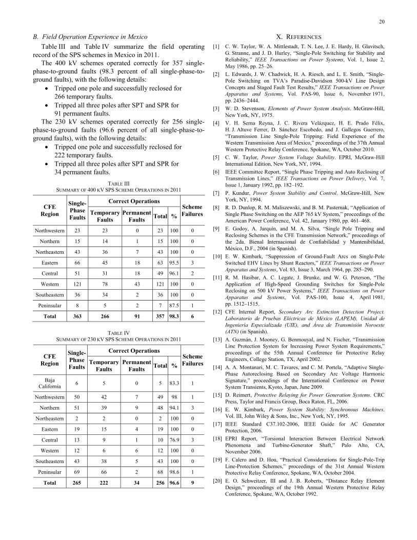
B. Field Operation Experience in Mexico Table III and Table IV summarize the field operating
record of the SPS schemes in Mexico in 2011. The 400 kV schemes operated correctly for 357 single-
phase-to-ground faults (98.3 percent of all single-phase-to-ground faults), with the following details:
• Tripped one pole and successfully reclosed for 266 temporary faults.
• Tripped all three poles after SPT and SPR for 91 permanent faults.
The 230 kV schemes operated correctly for 256 single-phase-to-ground faults (96.6 percent of all single-phase-to-ground faults), with the following details:
• Tripped one pole and successfully reclosed for 222 temporary faults.
• Tripped all three poles after SPT and SPR for 34 permanent faults.
TABLE III SUMMARY OF 400 KV SPS SCHEME OPERATIONS IN 2011
CFE Region
Single-Phase Faults
Correct Operations Scheme FailuresTemporary
Faults Permanent
Faults Total %
Northwestern 23 23 0 23 100 0
Northern 15 14 1 15 100 0
Northeastern 43 36 7 43 100 0
Eastern 66 45 18 63 95.5 3
Central 51 31 18 49 96.1 2
Western 121 78 43 121 100 0
Southeastern 36 34 2 36 100 0
Peninsular 8 5 2 7 87.5 1
Total 363 266 91 357 98.3 6
TABLE IV SUMMARY OF 230 KV SPS SCHEME OPERATIONS IN 2011
CFE Region
Single-Phase Faults
Correct Operations Scheme FailuresTemporary
Faults Permanent
Faults Total %
Baja California 6 5 0 5 83.3 1
Northwestern 50 42 7 49 98 1
Northern 51 39 9 48 94.1 3
Northeastern 2 2 0 2 100 0
Eastern 19 15 4 19 100 0
Central 13 9 1 10 76.9 3
Western 12 6 6 12 100 0
Southeastern 43 38 5 43 100 0
Peninsular 69 66 2 68 98.6 1
Total 265 222 34 256 96.6 9
X. REFERENCES [1] C. W. Taylor, W. A. Mittlestadt, T. N. Lee, J. E. Hardy, H. Glavitsch,
G. Stranne, and J. D. Hurley, “Single-Pole Switching for Stability and Reliability,” IEEE Transactions on Power Systems, Vol. 1, Issue 2, May 1986, pp. 25–26.
[2] L. Edwards, J. W. Chadwick, H. A. Riesch, and L. E. Smith, “Single-Pole Switching on TVA’s Paradise-Davidson 500-kV Line Design Concepts and Staged Fault Test Results,” IEEE Transactions on Power Apparatus and Systems, Vol. PAS-90, Issue 6, November 1971, pp. 2436–2444.
[3] W. D. Stevenson, Elements of Power System Analysis. McGraw-Hill, New York, NY, 1975.
[4] V. H. Serna Reyna, J. C. Rivera Velázquez, H. E. Prado Félix, H. J. Altuve Ferrer, D. Sánchez Escobedo, and J. Gallegos Guerrero, “Transmission Line Single-Pole Tripping: Field Experience of the Western Transmission Area of Mexico,” proceedings of the 37th Annual Western Protective Relay Conference, Spokane, WA, October 2010.
[5] C. W. Taylor, Power System Voltage Stability. EPRI, McGraw-Hill International Edition, New York, NY, 1994.
[6] IEEE Committee Report, “Single Phase Tripping and Auto Reclosing of Transmission Lines,” IEEE Transactions on Power Delivery, Vol. 7, Issue 1, January 1992, pp. 182–192.
[7] P. Kundur, Power System Stability and Control. McGraw-Hill, New York, NY, 1994.
[8] R. D. Dunlop, R. M. Maliszewski, and B. M. Pasternak, “Application of Single Phase Switching on the AEP 765 kV System,” proceedings of the American Power Conference, Vol. 42, January 1980, pp. 461–468.
[9] E. Godoy, A. Jarquín, and M. A. Silva, “Single Pole Tripping and Reclosing Schemes in the CFE Transmission Network,” proceedings of the 2da. Bienal Internacional de Confiabilidad y Mantenibilidad, México, D.F., 2004 (in Spanish).
[10] E. W. Kimbark, “Suppression of Ground-Fault Arcs on Single-Pole Switched EHV Lines by Shunt Reactors,” IEEE Transactions on Power Apparatus and Systems, Vol. 83, Issue 3, March 1964, pp. 285–290.
[11] R. M. Hasibar, A. C. Legate, J. Brunke, and W. G. Peterson, “The Application of High-Speed Grounding Switches for Single-Pole Reclosing on 500 kV Power Systems,” IEEE Transactions on Power Apparatus and Systems, Vol. PAS-100, Issue 4, April 1981, pp. 1512–1515.
[12] CFE Internal Report, Secondary Arc Extinction Detection Project. Laboratorio de Pruebas Eléctricas de México (LAPEM), Unidad de Ingeniería Especializada (UIE), and Área de Transmisión Noroeste (ATN) (in Spanish).
[13] A. Guzmán, J. Mooney, G. Benmouyal, and N. Fischer, “Transmission Line Protection System for Increasing Power System Requirements,” proceedings of the 55th Annual Conference for Protective Relay Engineers, College Station, TX, April 2002.
[14] A. A. Montanari, M. C. Tavares, and C. M. Portela, “Adaptive Single-Phase Autoreclosing Based on Secondary Arc Voltage Harmonic Signature,” proceedings of the International Conference on Power System Transients, Kyoto, Japan, June 2009.
[15] D. Reimert, Protective Relaying for Power Generation Systems. CRC Press, Taylor and Francis Group, Boca Raton, FL, 2006.
[16] E. W. Kimbark, Power System Stability: Synchronous Machines. Vol. III, John Wiley & Sons, Inc., New York, NY, 1995.
[17] IEEE Standard C37.102-2006, IEEE Guide for AC Generator Protection, 2006.
[18] EPRI Report, “Torsional Interaction Between Electrical Network Phenomena and Turbine-Generator Shaft,” Palo Alto, CA, November 2006.
[19] F. Calero and D. Hou, “Practical Considerations for Single-Pole-Trip Line-Protection Schemes,” proceedings of the 31st Annual Western Protective Relay Conference, Spokane, WA, October 2004.
[20] E. O. Schweitzer, III and J. B. Roberts, “Distance Relay Element Design,” proceedings of the 19th Annual Western Protective Relay Conference, Spokane, WA, October 1992.

21
[21] G. Benmouyal and J. Mahseredjian, “A Combined Directional and Faulted Phase Selector Element Based on Incremental Quantities,” IEEE Transactions on Power Delivery, Vol. 16, Issue 4, October 2001, pp. 478–484.
[22] G. E. Alexander, J. B. Mooney, and W. Z. Tyska, “Advanced Application Guidelines for Ground Fault Protection,” proceedings of the 28th Annual Western Protective Relay Conference, Spokane, WA, October 2001.
[23] D. Hou, A. Guzmán, and J. Roberts, “Innovative Solutions Improve Transmission Line Protection,” proceedings of the 24th Annual Western Protective Relay Conference, Spokane, WA, October 1997.
[24] H. J. Altuve Ferrer and E. O. Schweitzer, III (eds.), Modern Solutions for Protection, Control, and Monitoring of Electric Power Systems. Schweitzer Engineering Laboratories, Inc., Pullman, WA, 2010.
[25] F. Calero, A. Guzmán, and G. Benmouyal, “Adaptive Phase and Ground Quadrilateral Distance Elements,” proceedings of the 36th Annual Western Protective Relay Conference, Spokane, WA, October 2009.
[26] G. Benmouyal, “The Trajectories of Line Current Differential Faults in the Alpha Plane,” proceedings of the 32nd Annual Western Protective Relay Conference, Spokane, WA, October 2005.
XI. BIOGRAPHIES Elizabeth Godoy received her BS in electrical engineering in 1991 and an MSc in power system engineering in 1993 from the National Autonomous University of Mexico, Mexico City. In 1995, she joined Comisión Federal de Electricidad (CFE) as an operation auxiliary engineer of the National Energy Control Center. Since 1997, Miss Godoy has served in the protection department of the CFE Transmission Sub Direction. Her main task is performing stability and electromagnetic transient studies of the CFE transmission network.
Alberto Celaya received his BS in electrical engineering in 1990 from the Hermosillo Technological Institute. In 1990, he joined the Western Control Area of Comisión Federal de Electricidad (CFE). Mr. Celaya has served as system operator of the Hermosillo Sub Area, operation auxiliary engineer, and power system engineer. Since 1997, he has been the head of the Analysis Department of the CFE Western Control Area. His main task is performing studies for planning the operation and control of the CFE western electric grid.
Héctor J. Altuve received his BSEE degree in 1969 from the Central University of Las Villas in Santa Clara, Cuba, and his Ph.D. in 1981 from Kiev Polytechnic Institute in Kiev, Ukraine. From 1969 until 1993, Dr. Altuve served on the faculty of the Electrical Engineering School at the Central University of Las Villas. From 1993 to 2000, he served as professor of the Graduate Doctoral Program in the Mechanical and Electrical Engineering School at the Autonomous University of Nuevo León in Monterrey, Mexico. In 1999 through 2000, he was the Schweitzer Visiting Professor in the Department of Electrical Engineering at Washington State University. Dr. Altuve joined Schweitzer Engineering Laboratories, Inc. (SEL) in January 2001, where he is currently a distinguished engineer and the dean of SEL University. He has authored and coauthored more than 100 technical papers and several books and holds four patents. His main research interests are in power system protection, control, and monitoring. Dr. Altuve is an IEEE senior member.
Normann Fischer received a Higher Diploma in Technology, with honors, from Witwatersrand Technikon, Johannesburg in 1988, a BSEE, with honors, from the University of Cape Town in 1993, and an MSEE from the University of Idaho in 2005. He joined Eskom as a protection technician in 1984 and was a senior design engineer in the Eskom protection design department for three years. Normann then joined IST Energy as a senior design engineer in 1996. In 1999, he joined Schweitzer Engineering Laboratories, Inc. as a power engineer in the research and development division. Normann was a registered professional engineer in South Africa and a member of the South Africa Institute of Electrical Engineers. He is currently a senior member of IEEE and a member of ASEE.
Armando Guzmán received his BSEE with honors from Guadalajara Autonomous University (UAG), Mexico, in 1979. He received a diploma in fiber-optics engineering from Monterrey Institute of Technology and Advanced Studies (ITESM), Mexico, in 1990, and his MSEE from the University of Idaho, USA, in 2002. He served as regional supervisor of the Protection Department in the Western Transmission Region of the Federal Electricity Commission (the Mexican electrical utility company) in Guadalajara, Mexico, for 13 years. He lectured at UAG and the University of Idaho in power system protection and power system stability. Since 1993, he has been with Schweitzer Engineering Laboratories, Inc., in Pullman, Washington, where he is a research engineering manager. He holds numerous patents in power system protection and metering. He is a senior member of IEEE and has authored and coauthored several technical papers.
© 2012 by Comisión Federal de Electricidad and Schweitzer Engineering Laboratories, Inc.
All rights reserved. 20120912 • TP6579-01