tripping of asymmetrical stiffeners under combined...
TRANSCRIPT
University Research ProgramReport No. MA... RD-840-88035
TRIPPING OFASYMMETRICAL STIFFENERSUNDER COMBINED LOADING
Final Report
by
Alexis OstapenkoDongho Yoo
Fritz Engineering Laboratory Report No. 513.3
August 1988
u. S. DEPARTMENT OF TRANSPORTATIONMaritime Administration
Office of Research and Development
Maritime Administration University Research Program
Report No. MA-RD-840-88035
TRIPPING OF ASYMMETRICAL STIFFENERS
UNDER COMBINED LOADING
Prepared by
Alexis OstapenkoDongho Yoo
LEHIGH UNIVERSITYFritz Engineering Laboratory
Bethlehem, P A
Fritz Engineering Laboratory Report No. 518.3
August 1988
U. S. DEPARTMENT OF TRANSPORTATION, Maritime AdministrationOffice of Research and Development
MA-RD-840-88035 (F.E.L. 513.3)
LEGAL NOTICE
This report was prepared as an ac.count of government-sponsored work. Neither the·United States, nor the Maritime Administration, nor any person acting on behalf of theMaritime Administration
(A) Makes any warranty or representation, expressed or implied, with respect to theaccuracy, completeness or usefulness of the information contained in this report,or that the use of any information, apparatus, method, or process disclosed inthis report may not infringe privately o\vned rights; or
(B) Assumes any liabilities with respect to the -lise of or for damage resulting fromthe use of any information, apparatus, method, or process disclosed in this report.
As used in the above, "persons acting .on behalf of the Maritime Administration" includes any employee or contractor of the Maritime Administration to the extent thatsuch employee or contractor of the Maritime Administration prepares, handles, or distributes, or provides access to any information pursuant to his employment or contractwith the Maritime Administration.
---.. ,.. .........
TRIPPING OF ASYMMETRICAL STIFFENERSUNDER COMBINED LOADING
... ttl "I ' L t?".
..........Agust 1988
,. WMrCI)
Alexis Ostapenko and Dongho Yoo& ............ Orpn'.......... No.
F.E.L. Report No. 513.3I .............. Orpn&utteft ..................
Lehigh UniversityDepartment of Civil EngineeringFritz Engineering Laboratory #13Bethlehem, PA 18015
II. CIIt IIIJIIC'C) ......0) ....
~ DTMA91-86-C-60117
•1& ....e....... Ofpfttaet............... a.NNu
U.s. Department of TransportationMaritime Administr'ation .Office of Research and Developmentl.J~Qh;nor()n n (; 20SQO
FINAL REPORT
II. ......fM...~ ......
Research was conducted underthe Maritime Administration University Research Program
.1. MIItfMt (UtNt: 100 .....)
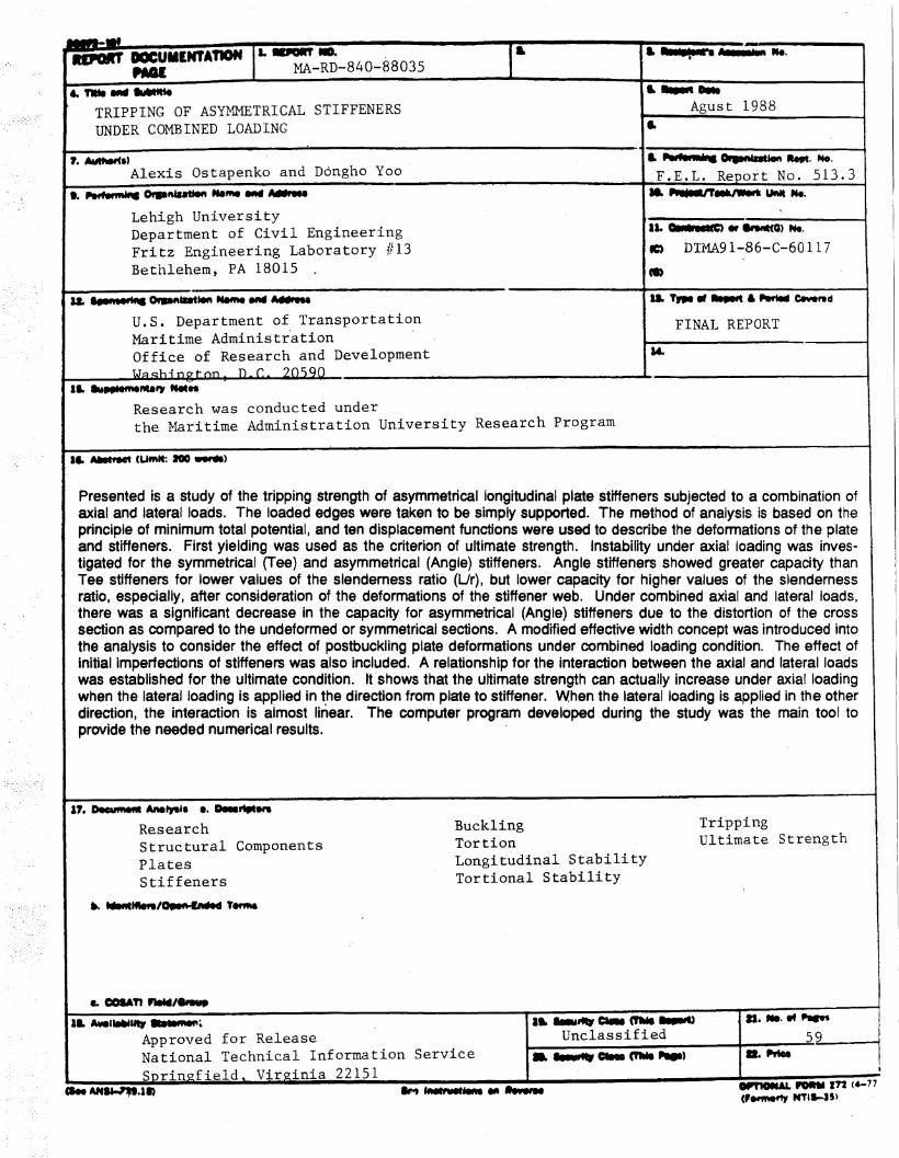
Presented is a study of the tripping strength of asymmetrical longitudinal plate stiffeners subjected to a combination ofaxial and lateral loads. The loaded edges were taken to be simply supported. The method of analysis is based on theprinciple of minimum total potential, and ten displacement functions were used to describe the deformations of the plateand stiffeners. First yielding was used as the criterion of ultimate strength. Instability under axial (oading was investigated for the symmetrical (Tee) and asymmetrical (Angle) stiffeners. Angle stiffeners showed greater capacity thanTee stiffeners, for lower values of the slenderness ratio (Ur), but lower capacity for higher values of the slendernessratio, especially, after consideration of the deformations of the stiffener web. Under combined axial and lateral loads,there was a significant decrease in the capacity for asymmetrical (Angle) stiffeners due to the distortion of the crosssection as compared to the undeformed or symmetrical sections. A modified effective width concept was introduced intothe analysis to consider the effect of postbuckling plate deformations under combined loading condition. The effect ofinitial imperfections of stiffeners was also included. A relationship for the interaction between the axial and lateral loadswas established for the ultimate condition. It shows that the ultimate strength can actually increase under axial loadingwhen the lateral loading is applied in the direction from plate to stiffener. When the lateral loading is applied in the otherdirection) the interaction is almost linear. The computer program developed during the study was the main tool toprovide the needed numerical results.
17. DIcufM.. AM~'. e. a...........ResearchStructural ComponentsPlatesStiffeners
•• ......1tIIft/~ , .....
BucklingTortianLongitudinal StabilityTortional Stability
TrippingUltimate Strength
a ..............59
•-. ........ ca.. CI'MI 11IIIII')
UnclassifiedIL-'-I..................~
Approved for ReleaseNational Technical Information ServiceSnrin~field, Virginia 22151
", .
MA-RD-840-88035 (F.E.L. 513.3)
Table of Contents'
ABSTRACT1. INTRODUCTION
1.1 Introduction1.2 General Description of the Problem
2. LITERATURE REVIEW3. SUMMARY OF CURRENT STUDY4. METHOD OF ANALYSIS
4.1 Principle of Minimum Total Potential4.2 Overall Deformation of Stiffened Plate4.3 Plate Deformations4.4 Stiffener Deformations
4.4.1 Deformation of Stiffener Web4.4.2 Deflection of Stiffener Flange4.4.3 Deformation of Stiffener Section
4.5 Loading Conditions4.5.1 Axial Loading4.5.2 Lateral Loading4.5.3 Combined Loading
4.6 Summary of Displacement Functions4.7 Plate in Postbuckling Range
4.7.1 Consideration of Effective Width --- General Formula4.7.2 Effective Width for Combined Loading
4.8 Consideration of Initial Imperfections4.9 Computer Program
5. RESULTS OF ANALYSIS5.1 Axial Loading
5.1.1 Buckling Modes5.1.2 Comparison of Buckling Strengths of Angle and Tee Stiffeners
5.2 Combined Loading5.2.1 Stiffener Deformations and Stress Distributions5.2.2 Maximum Stress5.2.3 Interaction Behavior
6. SUMMARY, CONCLUSIONS AND RECOMMENDATIONS6.1 Summary and Conclusions6.2 Recommendations
7. ACKNOWLEDGEMENTSREFERENCESA. TOTAL POTENTIAL ENERGY
A.l In~ernal Potential (Strain Energy)A.2 External Potential of Loaidng at Ends
TABLESFIGURESNOMENCLATURE
1
2
23
6
9
11
111213141415151616171818191920222223
23232425252627
29
2930
32
33
35
3537
38
4154
Figure 1:Figure 2:Figure 3:Figure 4:Figure 5:Figure 6::figure 7:Figure 8:Figure 9:Figure 10:
Figure 11:Figure 12:Figure 13:
Figure 14:
Figure 15:
Figure 16:
MA-RD-840-88035 (F.E.L. 513.3)
List of Figures
Various Types of Stiffener SectionAngle and Tee Stiffeners (Other Dimensions in Fig. 3)Geometry of Angle SectionDeformation of Stiffener WebUnit to be Analyzed and Loading Applied (in positive direction)Deformation (Buckling) ModesDefinitions of Constants in Assumed Displacement FunctionsBuckling of Stiffened PlatesBuckling Mode- Transition
General Comparison of Buckling Strength for Angle and TeeStiffenerStress Distribution under Combined LoadingModified Effective Width Concept under Combined LoadingInteraction between P and Q Considering the Effect of Slenderness RatioRatio of maximum stresses between deformed and undeformedsectionsInteraction between P and Q with Initial Imperfection (afr ==58.24)Flo\v Chart for Computer Program
II
41414242434445464748
484950
51
52
53

Table 1:Table 2:Table 3:
MA-RD-840-88035 (F .E.L. 513.3)
List of Tables
Literature SummaryComparison of Computed Results with Van der Neut's SolutionSection Properties of Specimens Used in Figures
111
384040
MA-RD-840-88035 (F .E.L. 513.3)
ABSTRACT
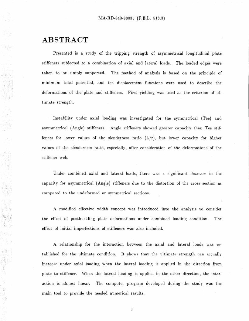
Presented is a study of the tripping strength of asymmetrical longitudinal plate
stiffeners subjected to a combination of axial and lateral loads. The loaded edges were
taken to be simply supported. The method of analysis is based on the principle of
minimum total potential, and ten displacement functions were used to describe the
deformations of the plate and stiffeners. First yielding was used as the criterion of ul
timate strength.
Instability under axial loading was investigated for the symmetrical (Tee) and
asymmetrical (Angle) stiffeners. Angle stiffeners showed greater capacity than Tee stif
feners for lo\ver values of the slenderness ratio (L/r), but lower capacity for higher
values of the slenderness ratio, especially, after consideration of the deformations of the
stiffener web.
Under combined axial and lateral loads, there was a significant decrease in the
capacity for asymmetrical (Angle) stiffeners due to the distortion bf the cross section as
compared to the undeformed or symmetrical sections.
A modified effective width concept was introduced into the analysis to consider
the effect of postbuckling plate deformations under combined loading condition. The
effect of initial imperfections of stiffeners was also included.
A relationship for the interaction between the axial and lateral loads was es
tablished for the ultimate condition. It shO\\T8 that the ultimate strength can actually
increase under axial loading when the lateral loading is applied in the direction from
plate to stiffener. When the lateral loading is applied in the other direction, the inter
action is almost linear. The computer program developed during the study \vas the
main tool to provid.e the needed numerical results.
1
MA-RD-840-88035 (F.E.L. 513.3)
1. INTRODUCTION
1.1 Introduction
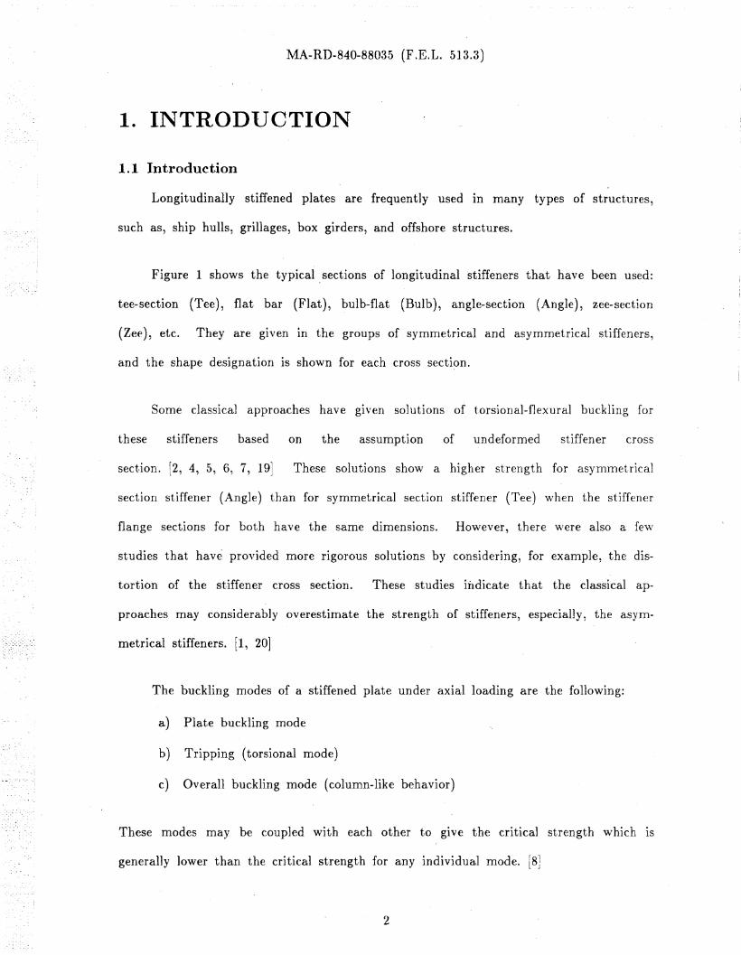
Longitudinally stiffened plates are frequently used in many types of structures,
such as, ship hulls, grillages, box girders, and offshore structures.
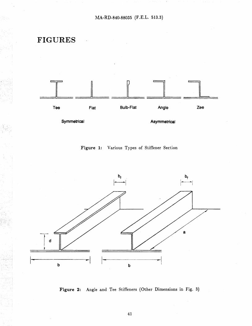
Figure 1 shows the typical. sections of longitudinal stiffeners that have been used:
tee~section (Tee), flat bar (Flat), bulb-flat (Bulb), angle-section (Angle), zee-section
(Zee), etc. They are given in the groups of symmetrical and asymmetrical stiffeners,
and the shape designation is shown for each cross section.
Some classical approaches have gIven solutions of torsional-flexural buckling for
these stiffeners based on the assumption of undefarmed stiffener cross
section. [2, 4, 5, 6, 7, 19] These solutions show a higher strength for aSYD1metrical
section stiffener (Angle) than for symmetrical section stiffener (Tee) \vhen the stiffener
flange sections far both have the same dimensions. However, there \vere also a fe\\r
studies that have provided more rigorous solutions by considering, for example, the dis
tortion of the stiffener cross section. These studies indicate that the classical ap
proaches may considerably overestimate the strength of stiffeners, especially, the asym
metrical stiffeners. f1, 20]
The buckling modes of a stiffened plate under axial loading are the following:
a) Plate buckling mode
b) Tripping (torsional mode)
c) Overall buckling mode (column-like behavior)
These modes may be coupled with each other to gIve the critical strength which IS
generally lower than the critical strength for any individual mode. [8J
2
MA-RD-840-88035 (F.E.L. 513.3)
The maXImum strength of a stiffened plate may be also controlled by yielding.
This would be particularly valid for panels under lateral loading or when there are in
itial imperfections. Especially for asymmetrical stiffeners, the effect of section distortion
becomes very important in computing the maximum stress when the section is checked
for initiation of yielding.
1.2 General Description of tIle Problem
The behavior and capacity of stiffened plates depend on the type of loading,
geometrical properties, type of section, aspect ratio and width-thickness ratio of the
plate, initial imperfections, material properties, etc.
The t\VO important representatives of the symmetrical and asymmetrical stiffeners
shown in Fig. 1 are the Tee and Angle sections. Thus, all quantitative discussions In
this study will be n1ade \vith respect to them. Since many geometrical" properties of
asymmetrical (Angle) stiffeners and symmetrical (Tee) stiffeners are different from each
other, all direct comparisons bet\veen Angle and Tee stiffeners will be n1ade after as
suming that the stiffener flange "\\ridth and thickness are exactly the same for both as
indicated in Fig. 2.
The most significant difference bet\veen the Angle and Tee stiffener sections is in
the value of the warping constant. The reason is that the reference point for the rota
tion of these stiffener sections is approximately at the junction of plate and stiffener,
not at the shear center of the stiffener section alone. This results in the Angle section
to have a significantly larger value of the warping constant than the Tee section. Fur
thermore, the reference point of flange rotation is also different from each other. For,
the Angle section, the flange has the reference point approximately at the web tip,
while the Tee section has it at the center of the flange. This is especially important
when the distortion of the cross section is included in the analysis.
3
MA-RD-840-88035 (F .E.L. 513.3)
In consequence, a classical torsional buckling analysis which assumes the cross sec
tion to be undeformable, gives a' higher strength for an asymmetrical section (Angle)
than for a symmetrical section (Tee). And this is reflected in the current design
recommendations. [6, 7, 11] However, some studies, such as, Van der Neut's, which
consider distortion of the cross section, point out' the opposite to be true, especially for
the column mode of failure. [20] Ho\vever, because of the non-recognition or the com
plexity of the problem, no specific design recommendations have yet been made for
asymmetrical stiffeners.
In addition to the torsional buckling behavior (the tripping mode), the plate
buckling behavior should be carefully taken into consideration, especially, when the
width-thickness ratio is relatively high. In the most studies done previously, the effect
of the plate on the stiffener motion was included simply by replacing the plate \vith a
rotational spring.(Table 1, Line 8) Thus, the major concern \\Tas put on the stiffener
behavior alone. Ho\vever, this may be only a crude approxima.tion. "Then the stif
fened plate buckles, there are several buckling mode shapes that should be
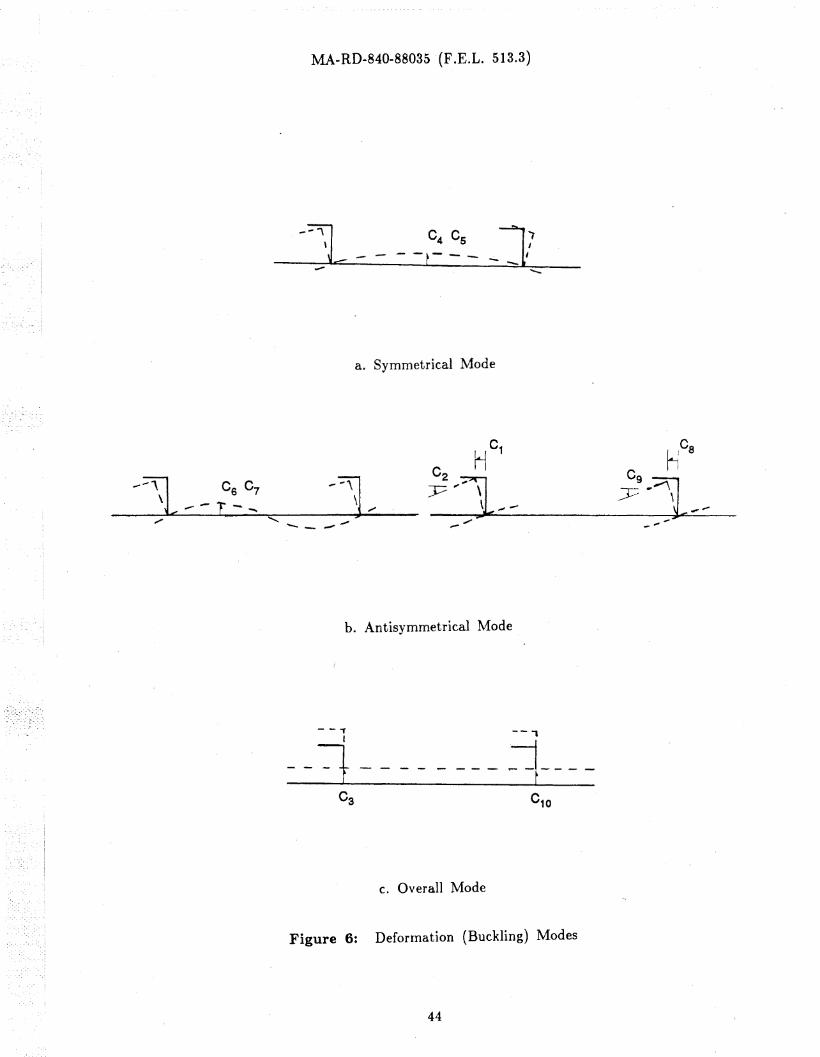
checked. [3, 19] The two most significa.nt mode shapes f?r plate buckling are the sym
metrical and antisymmetrical since they define the 'motion of two consecutive stiffeners
as indicated in Fig. 6; the symmetrical mode means that the two stiffeners have op
posite directions of motion (Fig. 6. a) and the antisymmetrical means that they have
the sa.me directions (Fig. 6. b).
So far, two buckling modes, the torsional buckling mode for the stiffener and the
flexural buckling mode for the plate, have been discussed. In addition to these, the
overall buckling mode of the whole structure should be considered as another
possibility. (It should be obvious that this mode becomes prevalent for larger values of
the slenderness ratio of the \\Thole structure.) In this mode, an asymmetrical section
4
MA-RD-840-88035 (F.E.L. 513.3)
would behave quite differently from a symmetrical section. One can easily see that the
buckling strength of a Tee section will be given by the Euler buckling strength since
the Tee section is symmetrical about its principal minor' axis and there is no preference
for the direction in which the section might rollover. The Angle section, on the other
hand, would introduce additional deformation components into the buckling mode, such
as, the sidesway bending of the flange and the consequent distortion and twisting.
Thus, one can expect that the Angle section would have its buckling strength lower
than the Euler column strength.
Buckling behavior of the plate alone depends on the restraint at side edges
provided by the stiffeners. Depending on the rigidity of the stiffeners, the' restraint
may be anY\\7here "rithin the range from simple support to fixed edg-e condition. It is
also possible that the torsional buckling of the stiffener \vill occur first and then force
the plate to buckle prematurely.
There is a need to obtain a solution which would consider complete interaction of
the effects of distortion of the stiffener cross section, of the buckling and postbuckling
behavior of the plate, and of the inelastic range.
5
MA-RD-840-88035 (F·.E.L. 513.3)
2. LITERATURE REVIEW
Very few of the papers describing the behavior of longitudinal stiffeners discuss
the effect of the distortion of stiffener cross section, especially for asymmetrical sec
tions, such as angle sections. The principal references dealing with asymmetrical stif
feners and stiffener distortion are reviewed here.
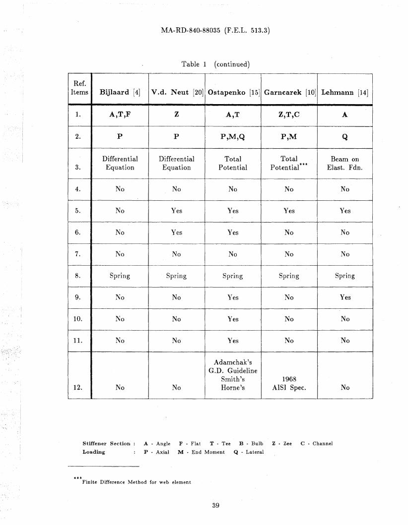
Table 1 shows the references studied in this investigation and the particular
topics covered by each reference, such as, the types of stiffener cross section (Tee,
Bulb, Flat-Bulb, Angle, or Zee) and loading condition (axial P, lateral Q, or bending
M). The method of analysis used and whether or' not tests ,,,,ere performed or
analyzed are also stated.
The controlling buckling mode of a gIven structure depends on the slenderness
ratio of the cross section (for the column buckling mode), the aspect and \vidth
thickness ratios of the plate (for the plate buckling mode), and the cross-sectional
properties of the stiffener (for the stiffener tripping mode). Unfortunately, no study is
available ""hich considered the interaction of all these modes for asymmetrical stiffeners.
\1an cler Neut studied the column mode with Zee stiffeners. l20] The important
contribution in his study was that pure Euler buckling mode cannot occur because
lateral bending of the flange and the distortion of the web accompany the column
buckling mode immediately from the start. The number of half "Taves of the defor
mation of the web was found to be the san1e as that of column buckling mode. Inclu
sion of the effect of deformability of the stiffener web resulted in a lower critical
strength than the pure Euler buckling strength. Also, he indicated that the antisym
metrical mode of plate, in other words, the motion of two consecutive stiffeners by the
same amount and in the same direction, is more critical than symmetrical buckling for
this type of buckling mode.
6
MA..RD-840-88035 (F.E.L. 513.3)
Ostapenko, uSIng a modification of the Van der Neut's approach, concluded that
the angle stiffeners are stronger than the tee stiffeners in the range of small slenderness
ratios (less than 20) because of the greater warping .constant of the angle section but
are weaker for· larger slenderness ratios. [15]
Adamchak described the behavior of symmetrical stiffeners (Tee) and suggested a
displacement function for the web plate in the form of a cantilever plate strip.
However, his formulation has an inconsistency of the equilibrium conditions at the
stiffener-plate junction. Adamchak assumed that the rotational spring constant of the
plate (agai!lst the stiffener motion) interacts linearly with the axial inplane stress in
the stiffeners. This approach means that, when the stress in the stiffener section
reaches the plate buckling stress, the rotational constraint would disappear. [1 ]
Lehmann regarded the flange of an asymmetrical section as a beam on elastic
foundation (foundation modulus due to the deformation of the web and plate) and as
being subjected to a certain f~rm of lateral loading. He \\'88 concerned mainly with
the effective width of the flange to be used in the equivalent cross section. [14, 16]
Bijlaard dealt with varIOUS types of stiffeners (Angle, Flat, and Tee) under com
pressive load. He gave a classical torsional-buckling solution of the stiffened plate and
also provided formulas for design approach based on his solution. Thus, neither plate
buckling nor distortion of the cross section were considered. [4]
Tests on Angle section stiffeners were conducted by Horne with a particular em
phasis on the effect of initial imperfections and residual stresses on the column
strength. The width-thickness ratio of the. plate was low to preclude plate
buckling. [13]
7
MA-RD-840-88035 (F.E.L. 513.3)
The general conclusion from the study of the references in Table 1 is that there
IS a need to consider alternate modes of stiffener tripping (symmetrical and
antisymmetrical), a more direct effect of the plate restraint than as a rotational spring,
and an interaction of the various deformation modes. Consideration also should be
given to the effects of cross-sectional distortion, initial imperfections and lateral loading.
8
MA-R'D-840-88035 (F.E.L. 513.3)
3. SUMMARY OF CURRENT STUDY
Current study was planned to fill some needs described in the previous chapters,
specifically, to formulate a method for analyzing the tripping (lateral-torsional) behavior
of asymmetric.al plate stiffeners subjected to axial or combined axial and lateral load
ing.
The Principle of Minimum Total Potential Energy and its extension, the
R,ayleigh-Ritz Method, were used as the basis for the method developed here. f5, 8, 19J
Reliability of this method depends on the displacement functions selected to duplicate
real deformations as closely as possible. The displacement functions were selected for
the overall deformation of stiffened plate, for the deformation of plate, and for the dis
tortion of stiffener web. To accommodate the possibility of symmetrical and antisym
metrical deformations of adjoining stiffeners, analysis \\Tas made on a typical t\\'O
stiffener unit with the tributary \vidth of plate.
The two loading cases, the axial loading and the combined loading, were analyzed
separately.
Axial loading was limited by the buckling strength. The strengths of asymmetri
cal (Angle) and symmetrical (Tee) stiffeners were compared and -controlling modes of
buckling defined. Main emphasis was put on the effect of distortion of the cross sec
tion.
Combined axial and la.teral loading applied to an asymmetrical section caused
continuous deformation rather than buckling. Using first yielding as the failure
criterion, the interaction between the uniformly distributed lateral loading and the axial
loading \-vas studied. One of. the complications \\'as the need to locate the point of
maximum stress in the cross section since, due to the distortion and sides\\ray motion
9
MA-RD-840-88035 (F.E.L. 513.3)
of the stiffener under· combined loads, the stress distribution In the section would con
stantly change. [14, 171 (Fig. 11)
Postbuckling strength of the plate and the effects of initial imperfections were in
corporated into the analysis. The effect of initial imperfections caused by the fabrica
tion process was also included in the analysis.
The analytical formulation was then implemented into a computer program which
can be used for parametric studies of the importance of the major controlling
parameters.
10
MA-RD-840-88035 (F.E.L. 513.3)
4. METHOD OF ANALYSIS
The method of analysis in this study relies on the principle of minimum total
potential energy. In this chapter, the method of applyip.g this principle, as well as, the
basic assumptions and concepts behind the application are explained.
4.1 Principle of Minimum Total Potential
Total potential energy V is equal to the sum of the internal potential (Strain
Energy U) and the external potential (Ve)'
V U+Ve (4.1)
The principle of minimum total potential states that the first variation of the total
potential with respect to the displacement field must be zero \\Then the system IS In
equilibrium. In other "'ords,
bVBV-owOw
o (4.2)
,,'"here \\' IS the defamation field and oW IS the variation of deformation.
The Ray leigh-Ritz method provides a practical engIneerIng application of the prln-
ciple of ll1inimum total potential energy by approximating the unknown displacement
field ,vith a serIes.
w " c.w.~ 1 1(4.3)
where each w. is a function of the indenpendent variables and must satisfy all thet
geometrical boundary conditions, and C i are the unknown constants.
Substitution of w from Eq. (4.3) makes the total potential a function of C i .
Then, the first variation of the total potential becomes a series of equations.
bV o
11
(4.4)
MA-RD-840-88035 (F .E.L. 513.3)
Since 6ei are arbitrary, the set of the simultaneous equations for the unknown Ci
IS
gIven by
BVac.
t
au aVe+ac. ac.
t t
o (4.5)
Displacement functions Wi for each component and their contributions to the To-
tal Potential are described in the subsequent sections. The equations for the whole
system are summarized in Appendix A.
4.2 Overall Deformation of Stiffened Plate
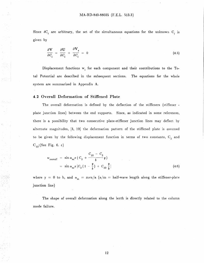
The overall deformation is defined by the deflection of the stiffeners (stiffener -
plate junction lines) bet\veen the end supports. Since, as indicated in some references,
there is a possibility that two consecutive plate-stiffener junction lines may deflect by
alternate magnitudes, [3, 19] the deformation pattern of the stiffened plate is ~ssumed
to be given by the follo\ving displacement function in terms of two constants, C3
and
CIO: (See Fig. 6. c)
woverall
c10
- C3
sin O:m x (C3 + bY)
sin G:mx [Gs (1 - ~) + GIO ~] (4.6)
where y == 0 to b, and 0:m
junction line)
rn1fx/a (aim half-lhrave length along the stiffener-plate
The shape of overall deformation along the lenth 18 directly related to the column
mode failure.
12
MA-RD-840-88035 (F.E.L. 513.3)
4.8 Plate Deformations
As shown in Fig. 6, several buckling modes of stiffened plates are possible. [2, 3)
The likelihood of a specific mode to dominate is dependent on the aspect ratio, slender..
ness ratio, and other geometrical and material properties.
Generally, the critical mode occurs when the plate has one half-wave in the trans..
verse direction between the edge boundaries (symmetrical mode), but some references
indicate that the antisymmetrical mode may be more critical for plates with angle type
stiffeners. [2, 3, 20] For example, Van der Neut took the antysimmetrical mode into
account in his analysis of the overall column buckling.
In the formulation of total potential in the current study, both modes are con-
sidered concurrently, and the solution sho\\'s which one is dominant for a particular
section.
Keeping these considerations In mind, the displacement function for each mode
\\ras assumed as follows .
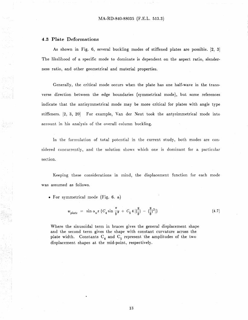
• For symmetrical mode (Fig. 6. a)
Wplate· {C · 1r Cs 4 [(-bY) - (-bY) 2] }Sin anX 4 SIn bY + (4.7)
Where the sinusoidal term In braces gives the general displacement shapeand the second term gives the shape with constant curvature across theplate width. Constants C
4and C~ represent' the amplitudes of the two
displacement shapes at the mid-point, respectively.
13
MA-RD-840-88035 (F.E.L. 513.3)
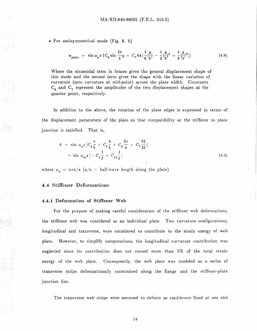
• For antisymmetrical mode (Fig. 6. b)
Wplate1 y 2 1 y 3- (-) + - (-) ]}2 b 3 b
(4.8)
Where the sinusoidal term in braces gives the general displacement shape ofthis mode and the second term gives the shape with the linear variation ofcurvature (zero curvature at mid-point) across the plate \\Tidth. ConstantsC6 and C 7 represent the amplitudes of the two displa.cement shapes at the
quarter point, respectively.
In addition to the above, the rotation of the plate edges 1S expressed in terms of
the displacement parameters of the plate so that compatibility at the stiffener to plate
junction is satisfied. That IS,
1f 4 2n 32e sin QnX [C4 b + Cs /; + C6b + C73b ]
1 1+ sin O'.m x [-C3b + GlOb] (4.9)
where an == lln-x/a (a/n == half-\vave length along the plate)
4.4 Stiffener Deforll1a.tions
4.4.1 Deformation of Stiffener Web
For the purpose of making careful consideration of the stiffener ",reb deformations,
the stiffener web was considered as an individual plate. Two curvature configurations,
longitudinal and transverse, were considered to contribute to the strain energy of web
plate. However, to simplify computations, the longitudinal curvature contribution \vas
neglected since its contribution does not exceed more than 5% of the total strain
energy of the web plate. Consequently, the web plate \vas modeled as a series of
transverse strips deformationally constrained along the flange and the stiffener-plate
junction line.
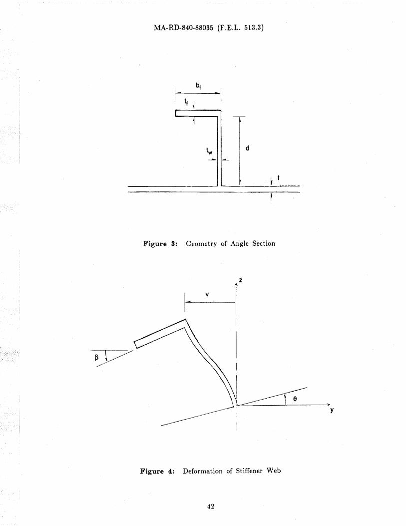
The transverse web strips were assumed to deform as cantilevers fixed at one end
14
MA-R'D-840-88035 (F .E.L. 513.3)
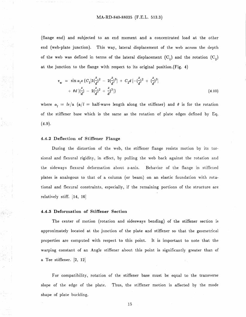
(flange end) and subj~cted to an end moment and a concentrated load at the other
end (web-plate junction). This way, lateral displacement of the web across the depth
of the web was defined in terms of the lateral displacement eel) and the rotation (02)
at the junction to the flange with respect to its original position.(Fig. 4)
z z z zVw = sin (XIx {C1[3(d)2 - 2(d)3] + C2d [-(d)2 + (d)3]
+ Od [(::) - 2(::)2 + ::)3]}d d d
(4.10)
where 0:: 1 == llr/a (a/l == half-wave length along the stiffener) and e is for the rotation
of the stiffener base which if? the same as the rotation of piate edges defined by Eq.
(4.9).
4.4.2 Deflection of Stiffeller Flange
During the distortion of the web, the stiffener flange resists motion by its tor-
sional and flexural rigidity, in effect, by pulling the 'Neb back against the rotation and
the sideways flexural deformation about z-axis. Behavior of the flange in stiffened
plates is analogous to that of a column (or beam) on an elastic foundation \vith rota-
tional and flexural constraints, especially, if the remaInIng portions of the structure are
relatively stiff. [14, 161
4.4.3 Deformation of Stiffener Section
The center of motion (rotation and sidesways bending) of the stiffener section is
approximately located at the junction of the plate and stiffener so that the geometrical
properties are computed with respect to this point. It IS important to note that the
warping constant of an Angle stiffener about this point IS significantly greater than of
a Tee stiffener. [2, 121
For compatibility, rotation of the stiffener base must be equal to the transverse
slope of the edge of the plate. Thus, the stiffener motion is affected by the mode
shape of plate buckling.
15
MA-RD-840-88035 (F .E.L. 513.3)
The angle of fl.ange rotation is the same as the angle of web edge rotation
(parameter 02) and this is the angle which is used in computing torsional strain energy
of the flange. ,However, torsional strai~ energy of the stiffener web is computed by
using the angle of rotation at the \veb base (e) (the rotation at the plate edge) and
the rest of strain energy in the stiffener is due to the flexural motion of the web strips
defined by Eq. (4.10).(Fig. 4) Note that when web distortion is neglected, rotations of
the flange and web base are the same.
4.5 Loading COllditions
4.5.1 Axial Loadi~g
Under axial loading only, the problem IS to find the ffilnlmum eigenvalue
(buckling strength) of the system. In general, two buckling modes can be shown to
control the instability.
• plate buckHng mode (edges remalllS In the original position)
• column-like buckling ~ode (overall buckling mode, when the whole structuredeflects, not just the plate)
The buckling mode of a gIven structure will depend· on a number of parameters~
such as, the width-thickness ratio of the plate (bit), overall slenderness ratio (a/r), the
type (Angle or Tee) and proportions of the stiffener section, the depth-breath ratio
(d/b) of the stiffener web, and so OD.
The external potential of axial loading is expressed by
(4.11)
where A represents the cross-sectional area of structure, and 0 is the relative axial dis-
plac.ement of the loaded cross section from the original position. This relative displace-
16
MA-R,D-840-88035 (F.E.L. 513.3)
ment of the two ends· of the structure at a fiber location (x,y) IS caused by curvature
(neglecting axial strains).
li a au av6(x,y) == - [(_)2 + (a'y)2] dz2 0 ax (4.12)
The external work for the whole system is presented In detail In Appendix A.
4.5.2 Lateral Loadillg
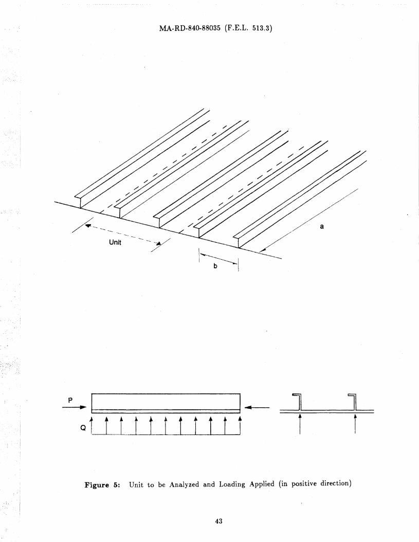
Lateral loading is taken as a uniform line load Q over the full length of the
structure and applied at the junction line of the stiffener and plate. The positive
direction of this loading is upward as shQ\vn in Fig. 5.
The external potential due to lateral loading for a two-stiffener unit IS gIven by
(4.13)
\vhere C3
and CIO
represent the amplitudes of the displacement functions.
Analysis of asymmetrical sections (Angle) shows that, under lateral loading, ad-
ditional stresses develop in the flange due to the lateral bending and rotation of the
linearly across the flange width. Accordingly, the maximum stress occurs at either of
stiffener section. These stresses are not uniform as for Tee stiffeners; they vary
the flange edges or in the plate depending on the direction of lateral loading and
geometrical proportions. The stress in the flange is then
with the compressive stress being positive. Note that the stress in the plate IS given
by the first term of Eq. (4.14) alone used with the corresponding value of z.
Qa 2/ 8
+ Ev"yI ZY
(4.14)
17
MA-RD-840-88035 (F.E.L. 513.3)
4.5.3 Combined Loading
When the stiffened plate IS subjected to a combination of axial and lateral load-
lng, the stress distribution becomes more complex, in particular, the location of the
maximum stress becomes more indefinite. As an illustration, the stiffener deformation
under lateral laoding, such as, sidesways bending of the flange section, will be affected
if there is also axial loading. In this case, axial loading can have a beneficial effect
for a flange section under positive lateral loading or accelerate the flange deformation
under negative lateral loading. Both axial and lateral loading interact with each other
to meet the First Yield Criterion at the location of the maximum stress~
P
A
Pe-z -I
y
Qa 2 /8I z + Ev"yy
(4.15)
where e is the vertical deflection of the \vhole structure due to loading applied, and the
stress in the plate is' given by the first three terms of Eq. (4.15) with the correspond-
ing value of z.
Analysis which included all these effects was compared with the normal beam
analysis which does not consider cross-sectional distortion.
4.6 Summary of Displacement Functions
So far, the assumptions with respect to individual components have been
described. However, it can be concluded that one stiffener with its tributary plate can-
not successfully represent the behavior of the full structure (series of stiffeners) because
the consecutive stiffeners may deform in opposite directions. This happens in the case
of alternating overall deformations and in the case of the symmetrical mode of plate
buckling. The different types of motion of the consecutive stiffeners can be adequately
described by having a unit with two stiffeners and the tributary plate width as the
basic unit to be analyzed.(Figs. 5 and 7) The minimum number of displacement func-
18
, MA-RD-840-88035 (F.E.L. 513.3)
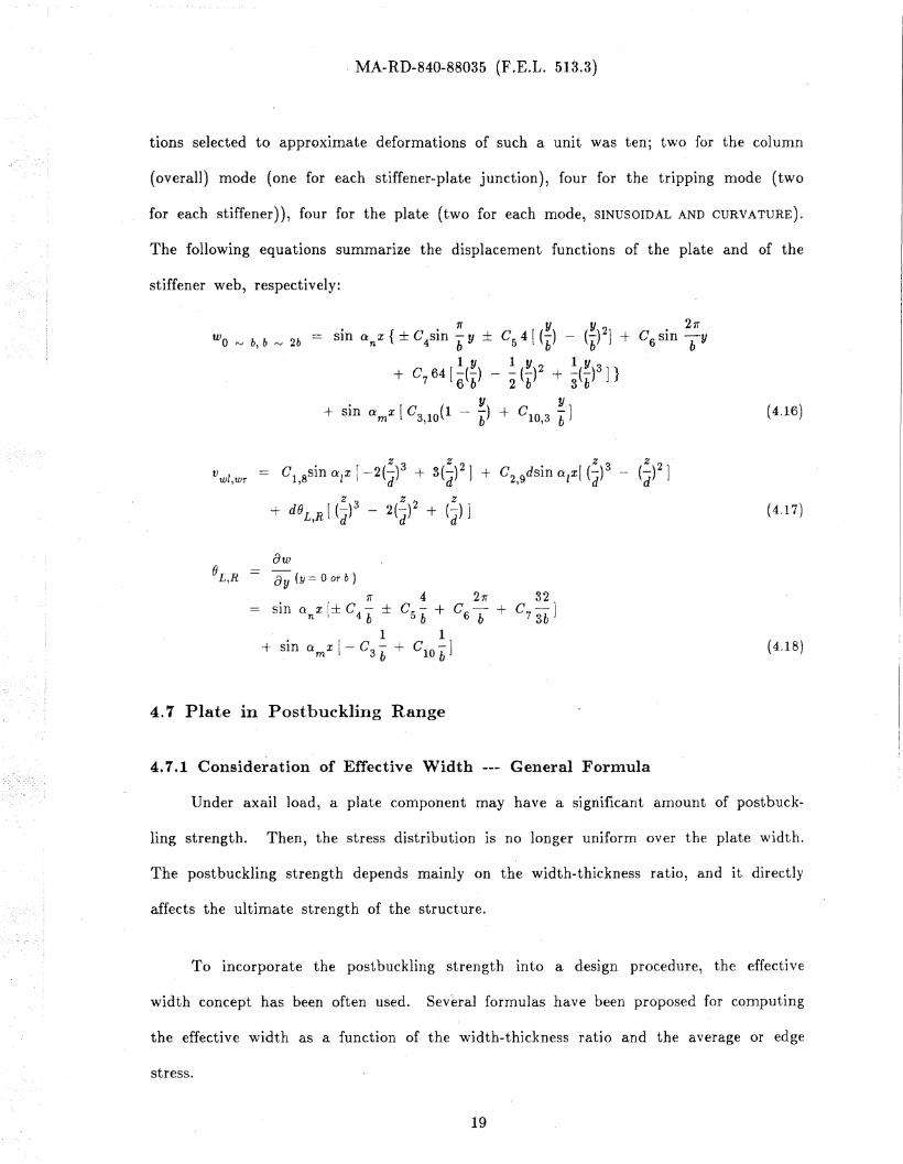
tions selected to approximate deformations of such a unit was ten; two for the column
(overall) mode (one for each stiffener-plate junction), four for the tripping mode (two
for each stiffener)), four for the plate (two for each mode, SINUSOIDAL AND CURVATURE).
The following equations summarIze the displacement functions of the plate and of the
stiffener web, respectively:
Wo ~ b, b ~ 2b sin 0nx { ± C4sin ~ y ± C54 [(~) - (~)2] + C6sin 2b1l"y
+ C 64 [~(~) _ ~ (~)2 + ~(~)3]}7 6b 2 b 3b
+ sin 0mx [C3,IO(1 - ~) + CIO,3 ~] (4.16)
ow()L,R ay (y:= 0 or b )
n 4 2n 32sin 0: n X [± c4 b ± C5 b + C6 b + C7 3b ]
1 1+ sin CtmX [ - Cg b + C ID b]
4.7 Plate in Postbuckling Range
4.7.1 Consideration of Effective Width --- General Formula
(4.17)
(4.18)
Under axail load, a plate component may have a significant amount of postbuck-
ling strength. Then, the stress distribution is no longer uniform over the plate \vidth.
The postbuckling strength depends mainly on the width-thickness ratio, and it directly
affects the ultimate strength of the structure.
To incorporate the postbuckling strength into a design procedure, the effective
width concept has been often used. Several formulas have been proposed for computing
the effective width as a function of the width-thickness ratio and the average or edge
stress.
19
MA-RD-840-88035 (F .E.L. 513.3)
The following effective width formula was selected for use In this study. [9]
Jucr- ( 1 - 0.22ue J
u cr-) < 1.00
f
(4.19)
where ue == stress at the edge of plate (here, at the stiffener-plate junction)
U critical buckling stress of a simply supported platecr
Equation (4.19) is based on experimental results 'and incoporates the effects of
residual stresses and initial imperfections. Thus, depending on the width-thickness ratio
(bit), reduction of the actual \vidth may take place before the buckling stress of the
plate is reached. The limits of the effective \vidth are the ac.tual width (be/b == 1.0)
and the minimum width at the ultimate plate capacity assumed to be reached \.\Then
the edge stress ((Je) equals the yield stress of the material.
Since under axial loading, the stress In the plate IS constant over the length, the
effective width is also constant.
4.7.2 Effective Width for Conlbilled Loading
As stated previously, ultimate strength of the structure IS assumed to be reached
when the maximum stress in the cross section is equal to the yield stress. To find the
maximum stress and its location, it is necessary to consider the effect of sides\vay
bending of the flange section as well as of the overall beam deformations.
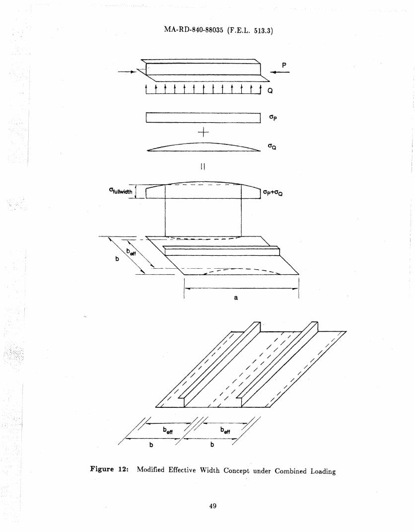
Under combined loading (P and Q), postbuckling deformation of the plate be-
tween stiffeners would accelerate failure of the structure. With the ends simply sup-
ported, the stress varIes parabolically along the structure and the maximum stress
would occur at mid-span. Since the effective width is a function of the stress in plate,
it would also vary parabolically with the smallest value at mid-span. In fact, depend-
ing on the stress variation, the effective width may have a full value near the ends
and a parabolic reduction over the middle portion as shown in Fig. 12.
20
MA-R'D-840-88035 (F.E.L. 513.3)
Nonlinear interdt::pendence among the effective width, the edge stress, overall
deformations, and the stress at other points In the cross section for a gIven loading
presents considerable difficulties in obtaining a solution. Numerical integration and
trial-and-error iteration computations would be involved. In order to simply the com-
putational procedure and eliminate the need for numerical integration, the effective
width was conservatively assumed to be constant over the full length and equal to the
value at mid-span. Then, iterations were needed only to bring the effective width and
the edge stress at mid-span into agreement. Generally, five to ten cycles were suf-
ficient to obtain a tolerance of 0.1 percent for the effective width.
At each load increment, a check of the stresses in the cross section (flange edges
and plate-stiffener junction) was made against the yield stress to pinpoint the reaching
of the ultimate load capacity. The maximum stress at each location considering the
reduced section (effective section) is, then,
P Pe Qa 2 /.8 Pee!!(J --z
-(lyle!!Z --z+ Ev"y (4.20)
A e!! (lyle!! (lyle!!
where the subscript "eff" generally means the effective section and its related properties,
while eeff represents the additional eccentricity due to the change of the section. The
stress in the plate is given by the first four terms of Eq. (4.20) with the corresponding
value of z.
Rotational interaction between the plate and the stiffener web was assumed not
to be affected by the postbuckling behavior of the plate and, thus, was based on the
full plate width.
21
MA-RD-840-88035 (F.E.L. 513.3)
4.8 COl1sideration of Initial Imperfections
Effect of initial imperfections on the behavior and strength of asymmetrical
(Angle) stiffeners was also considered under the combined axial and lateral loading con
dition. Two types of imperfection were considered to be most important; the overall
deflection of the stiffener in the vertical direction (perpendicular to the plate) and the
lateral deflection of the stiffener flange (parallel to the plate). The shape of the stif
fener was assumed not to change, and thus, the stiffener flange rotated through the
angle equal to the initial lateral deflection divided by the stiffener depth.
The pattern of initial imperfections \vas assumed to correspond to the displace
ment parameters and functions of the general formulation. Initial imperfections of the
plate were e_xpected to have very minor effect and were indirectly considered by the
use of the effective width concept. The computer program included the effect of initial
in1perfection.
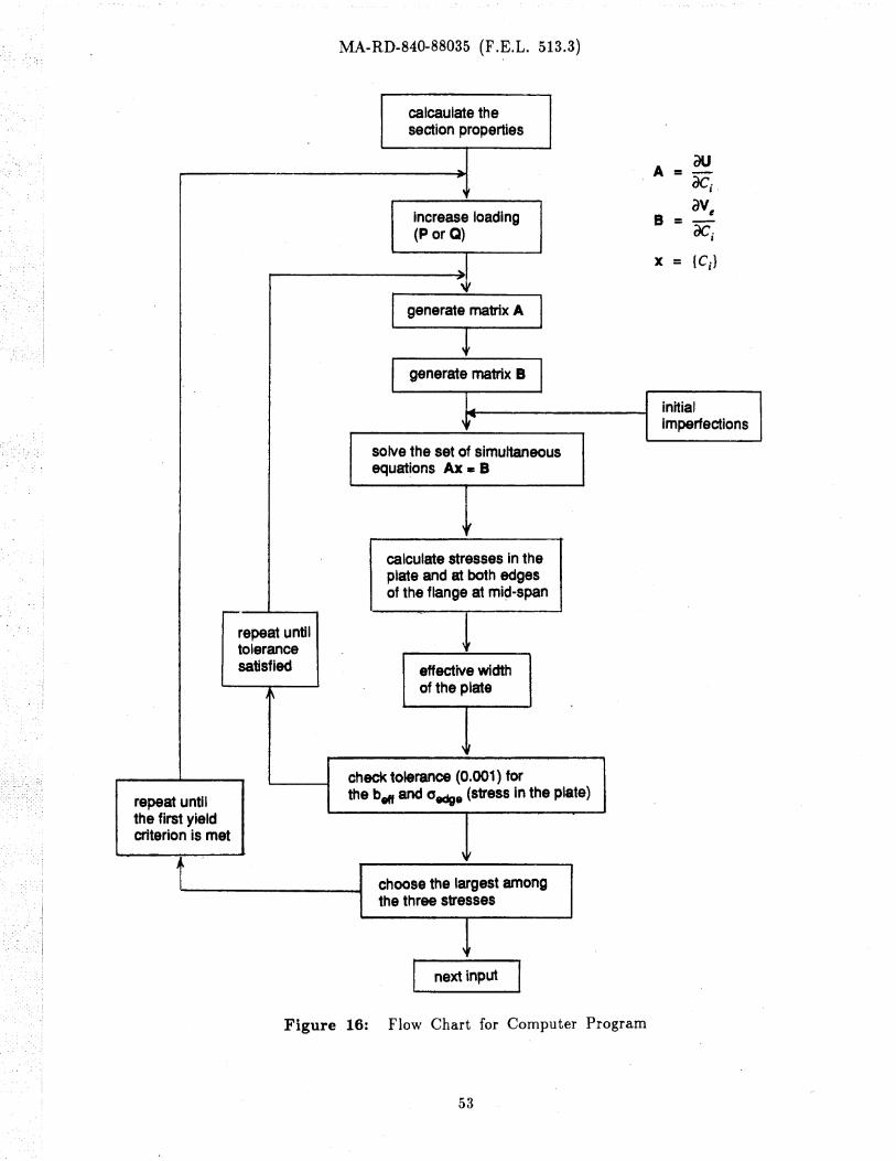
4.9 Computer Program
A computer program \vas written in FORTRAN-77 to implement. the method of
analysis described above. The program uses some outside routines for matrix opera
tions, such as, the solution of the eigenvalue problem (buckling under axial loading)
and the solution of simultaneous equations (behavior under combined loading). A self
explanatory outline of the program IS given by the flow chart in Fig. 16 for the case
of combined loading case. The direct consideration of the postbuckling behavior of the
plate (effective width) is incorporated through an interactive procedure for a specified
degree of tolerance (e.g., 0.001). In each cycle, the (lOxIO) coefficient matrix IS cor
respondingly adjusted, and the ultimate strength condition checked (first yield).
For the case of axial loading alone, (lateral loading == 0), the program IS
automatically adjusted and the buckling load is found as an eigenvalue.
22
MA-RD-840-88035 (F .E.L. 513.3)
5. RESULTS OF ANALYSIS
A computer program written to implement the method of analysis described in
the previous chapter was used to analyze some sample cases. The results obtained are
discussed here.
5.1 Axial Loading
5.1.1 Buckling Modes
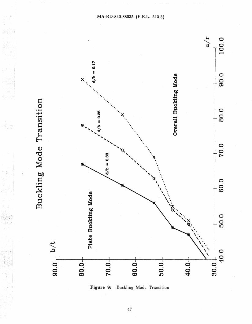
Results of a study of the predominance of a particular buckling mode in the elas-
tic range for asymmetrical stiffeners, the plate buckling or the overall buckling, are
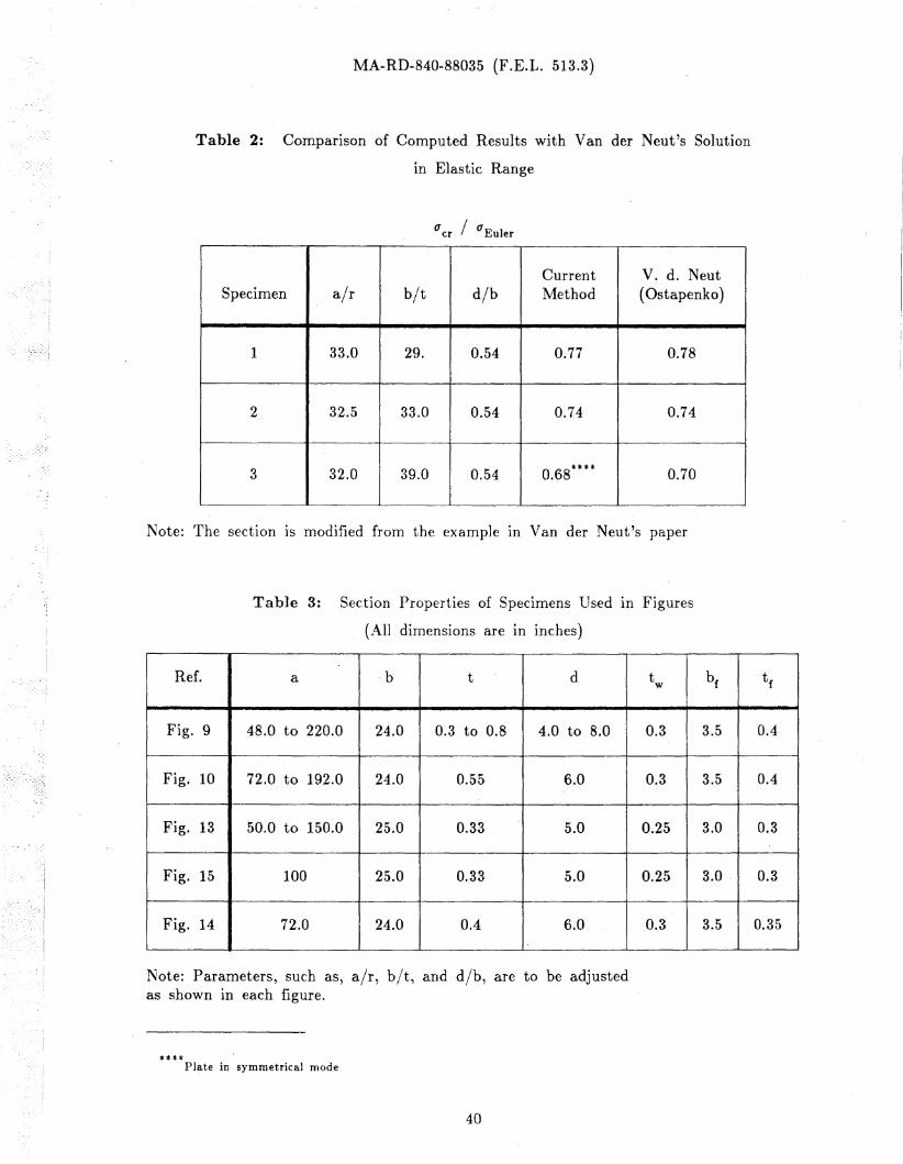
shown for three salnple sections in Fig. 9. (The dinlensions of these sections are listed
in Table 3) It can be seen that the controlling mode depends on the \vidth-thickness
ratio of the plate (bit), the slenderness ratio (a/r), and the stiffener depth to plate
width ratio (d/b).
The overall buckling mode computed for Fig. 9 incorporates the interaction of the
tripping and the column modes since for an asymmetrical section these two modes can-
not be indePE:ndent. ..t\lthough, as the structure becomes longer and longer (larger
slenderness ratio), the column mode becomes more dominant, the tripping mode of the
stiffener always accompanies it mainly due to the distortion of the stiffener cross sec-
tion. As indicated by Van der Neut, the corresponding plate deformations are likely to
be antisymmetrical. * [201 The effect of the coupling between the column and tripping
modes is illustrated in Table 2. Three specimens with the same angle stiffener but dif-
ferent plate V\!idths (different b It values) were analyzed using the proposed method, and
the buckling values were compared with the pure column (Euler) buckling load. Due
*. For symmetrical stiffeners (Tee), the plate buckling mode shape is expected to be symmetrical and to ac-company the tripping mode of the stiffener. The column buckling mode of Tee stiffeners is independent of theother modes, especially for larger slenderness ratios.
23
MA-RD-840-88035 (F.E.L. 513.3)
to the interaction of .the modes and the distortion of the cross section, the first two
specimens reached only 77% and 74% of the Euler load, respectively. The third
specimen failed with the plate deformation of the symmetrical mode at 68% of the
Euler load. The results of applying a computer program based on the method by Van
der Neut are also listed in Table 2. [15] The values are essentially the same as by
the proposed method, except that the possibility of symmetrical mode of plate defor
mation in the third specimen could not be detected since Van der Neut considered that
the antisymmetrical mode of the plate deformation was more critical for the overall
buckling mode and simply used the corresponding rotational constraint in the analysis.
5.1.2 Conlparison of ,Buckling Strengths of Allgle and Tee Stiffeners
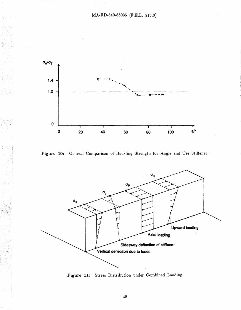
Figure 10 shoV\Ts a comparison of the buckling strength between Angle and Tee
stiffeners (the flanges of both are of the same proportions). The ratio of the Angle
strength to the Tee strength (0'A/O'T) is plotted against the slenderness ratio air.
For lower slenderness, the Angle stiffener has greater capacity than the Tee stif
fener mainly because of a greater warping constant of the angle to resist tripping. In
this region, the curve in Fig. 10 is above the uA/O'T ~ 1.0 line up to 1.42. This
agrees ¥lith the results of classical analysis which does not consider the effect of section
distortion. However, with, an increasing slenderness, the Angle section gradually be
comes weaker as indicated by the curve dropping below 1.0.
Although not shown directly, the computations made for the figure indicate that
Tee sections, especially for larger values of slenderness ratio (greater than 60 in
Fig. 10), have the buckling strength actually equal to the Euler buckling strength. On
the other hand, the Angle sections buckle in a coupled mode of the column and trip-,
ping modes and the buckling strength is less than the Euler strength or that of a Tee
section ((1A/(JT == 0.92 for air == 70). yTet , for very slend_er structures, (JA/(fT moves
closer to 1.0.
24
MA-R-D-840-88035 (F.E.L. 513.3)
5.2 Combined Loading
Only asymmetrical sections were studied under the combination of axial and
lateral loads because, under lateral loading, they are subject to a significant effect of
section distortion while symmetrical sections do not distort till after tripping of the
stiffener.
5.2.1 Stiffener Deformations and Stress Distributions
Under lateral loading, an asymmetrical (Angle) section starts to rotate about the
toe as well as to deflect vertically from the beginning of load application. The sides
way motion (rotation and distortion) makes the stress distribution vary over the flange
width. This variatioD of stresses over the cross section also changes along the stiffener.
The resultant stresses at mid-length can be expressed in terms of the curvature of
sidesway deformation of the flange (C1 6in~x).
The results of the analysis by the computer program show that the direction of
sidesway deformation of the stiffener depends on the direction of loading; for upward
(positive z direction In F'ig. 4) lateral loading, the stiffenet section tends to rotate
counterclockwise (that is, the flange moves into the negative y direction), and for
dO\\Tnward (negative z direction) lateral loading, the stiffener section tends to rotate
clockwise (the flange moves into the positive y direction). Accordingly, the defor
mation patterns for the two directions of lateral loading result in the stress distribu
tions across the flange width which are reversed from each other. An example of such
stress distributions is shown in Fig. 11; eac.h stress distribution is due to a particular
effect: vertical deflection of the whole structure ((Je)' sides\\Tay bending of the stiffener
section ((Jv), axial loading (ITp), and the upward (positive) lateral loading ((JQ)' respec
tively.
25
MA-RD-840-88035 (F.E.L. 513.3)
5.2.2 Maximum Stress
Since first yielding has been accepted as the criterion of failure, the location and
magnitude of the maximum stress in the cross section must be determined. While,
depending on the direction, lateral loading may cause tension· or compression at the
same location along the structure, the axial thrust always causes compression over the
whole cross section. Thus, the location and magnitude of the maximum stress depends
on the given loading condition.
For downward (negative) lateral loading, the maXImum stress occurs in the flange.
This is expected to be so since both, the axial thrust and lateral loading, cause com
pression in the flange. A some\vhat more complex situation exists in the case of an
upward (positive) lateral loading. If the axial thrust is kept constant and lateral load
ing gradually increased, then the location of the maximum stress (compression) Jumps
from its earlier position in the plate to the free edge of the flange (tension). This
shifting is attributed to the fact that there IS a. certain combination of loads which
makes the value of the tensile stress in the flange to be greater than the compression
stress in the plate.
Under a heavy axial thrust, the compression stress in the plate would reach the
yield stress with only a small amount of positive lateral loading before the tension
stress in the flange becomes significant. However, one must be very careful in analyz
ing such a case. Since the plate could be significantly deflected in the post-buckling
range, the stress distribution over the whole section would be affected. As indicated in
Chapter 4, the concept of effective width is introduced to take this effect into account.
26
MA-RD-840-88035 (F.E.L. 513.3)
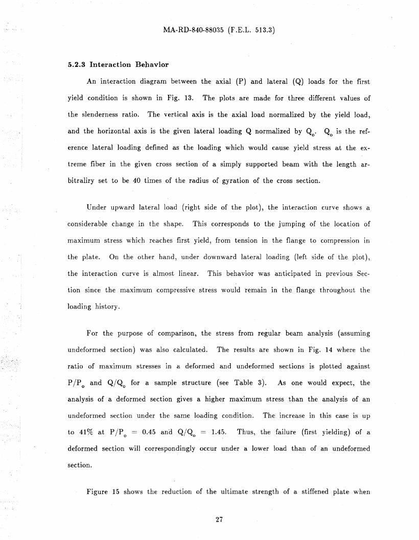
5.2.8 Interaction Behavior
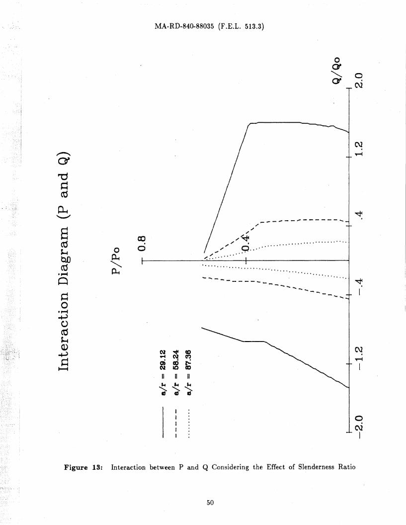
An interaction diagram between the axial (P) and lateral (Q) loads for the first
yield condition is shown in Fig. 13. The plots are made for three different values of
the slenderness ratio. The vertical axis is the axial load normalized by the yield load,
erence lateral loading defined as the loading which would cause yield stress at the ex-
treme fiber in the given cross section of a simply supported beam with the length ar-
and the horizontal axis is the given lateral loading Q normalized by Qo. Q is the ref-o
bitraliry set to be 40 times of the radius of gyration of the cross section.
Under upward lateral load (right side of the plot), the interaction curve shows a
considerable change In the shape. This corresponds to the jumping of the location of
maXImum stress '\vhich reaches first yield, from tension in the flange to compression In
the plate. On the other hand, under downward lateral loading (left side of the plot),
the interaction curve is almost linear. This behavior was anticipated in previous Sec-
tioD since the maximum compressive stress would 'remain in the flange throughout the
loading history.
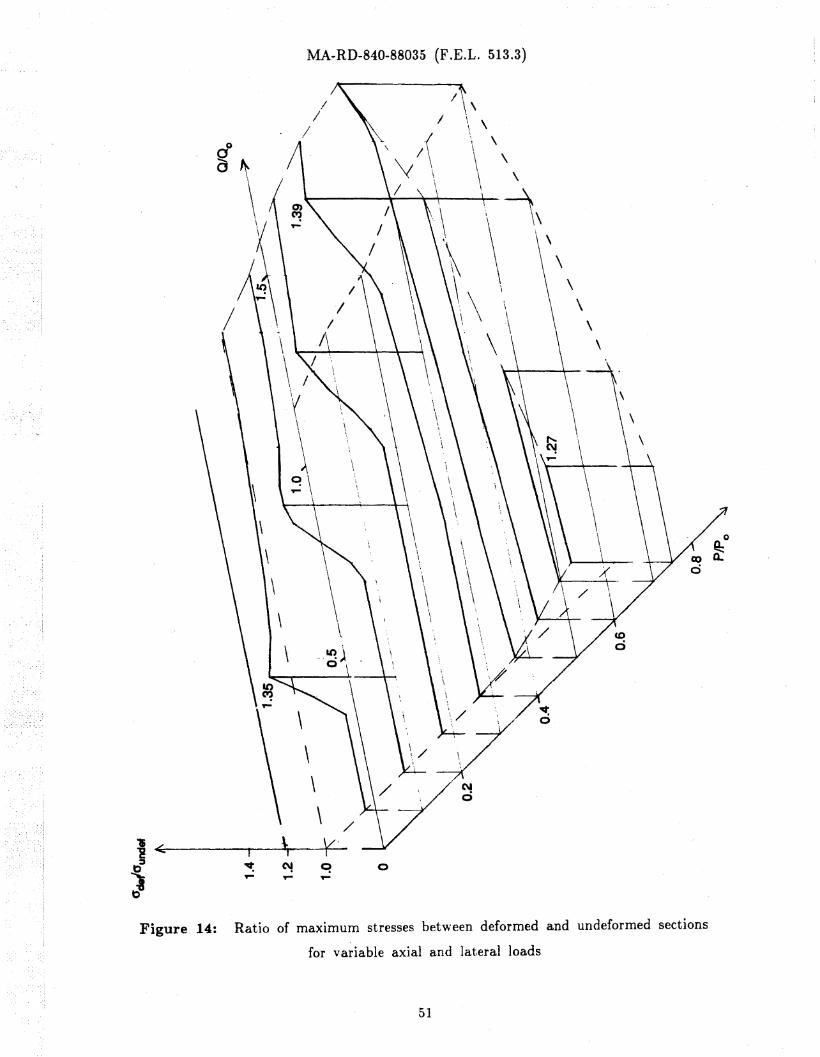
F or the purpose of comparIson, the stress from regular beam analysis (assuming
undeformed section) was also calculated. The results are shown in Fig. 14 where the
ratio of maximum stresses in a deformed and undeformed sections is plotted against
PIP 0 and Q/Qo for a sample structure (see Table 3). As one would expect, the
analysis of a deformed section gives a higher maximum stress than the analysis of an
undeformed section under the same loading condition. The increase in this case is up
to 41% at P IP 0 == 0.45 ana Q/Qo == 1.4~. Thus, the failure (first yielding) of a
,deformed section will correspondingly occur under a lower load than of .an undeformed
section.
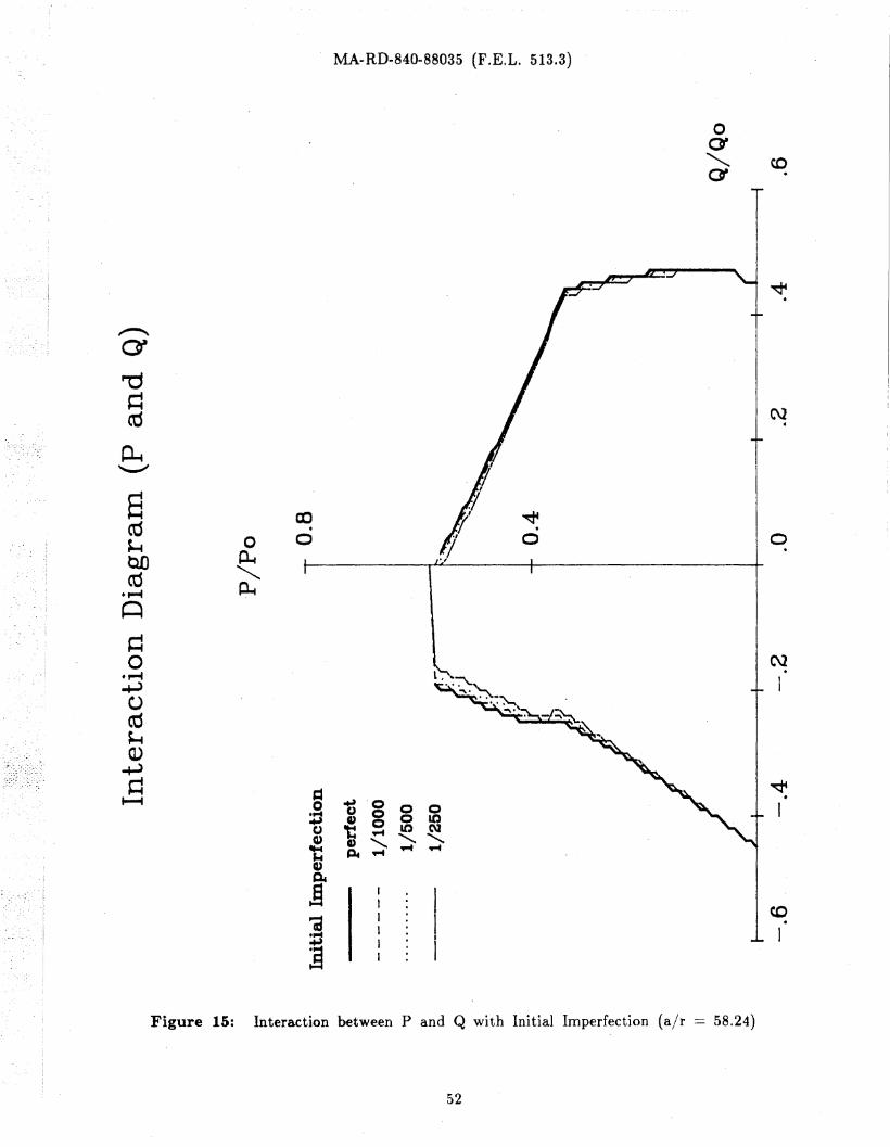
Figure 15 shows the reduction of the ultimate strength of a stiffened plate when
27
MA-RD-840-88035 (F .E.L. 513.3)
the effect of initial imperfection is taken into account. The imperfections were defined
as the initial lateral deflection of the flange in the (-y) direction and the (+z) deflec
tion of the stiffener-plate junction divided by the length of the stiffener for the upward
(+z) lateral load. The amounts of initial imperfection used in this figure were 1/1000,
1/500, and 1/250 of the length. The solid line is for the case without any imperfec
tions. As shown, for a combination of a heavy lateral and small axial loads, the effect
of initial imperfection is not very significant. However, for a greater axial loading, the
reduction of capacity becomes more important.
The ultimate capacity of the structure gradually decreases with the larger amount
of initial imperfection. For example, for the initial imperfection of 1/250, the reduction
of the capacity at Q/Qo == - 0.25 is approximately 15%.
28
MA-RD-840-88035 (F .E.L. 513.3)
6. SUMMARY, CONCLUSIONS ANDRECOMMEN'DATIONS
6.1 Summary and Conclusions
A method was developed for analyzing the tripping (lateral-torsional) behavior of
asymmetrical stiffeners in longitudinally 'stiffened plates subjected to axial or combined
axial and lateral loads. The effects of cross-sectional distortion, postbuckling behavior
of the plate (effective width), and initial imperfections were included. First yielding
was used as the criterion for ultimate loading condition.
A number of sample stiffened plates were analyzed to study varIOUS effects. The
cross section \vas assumed to distort or not to distort. Also, for the purpose of com-
parisan, in addition to asymmetrical (Angle) sections, symmetrical sections (Tee) \vith
the same flange dimensions \vere analyzed.
The follo\ving observations and conclusions can be drawn from the study:
Axial Loading
• Coupling of the buckling modes of plate buckling, tripping -and column bucklingwas found to give a significantly lower capacity of asymmetrical stiffeners, especially, when the effect of distortion of the cross section was considered.
• The effect of distortion depends on the slenderness ratio (a/r). In comparisonwith a symmetrical section (Tee), an asymmetrical section (Angle) has
o a higher capacity for lower values of air (up to 142% for the sectionanalyzed),
o a rapid reduction below the capacity of the Tee section (down to about92%) with an increase in air (for a classical solution, without distortion, thecapacity would remain above that of Tee),
o a very gradual increase toward the capacity of the Tee section for veryslender (long) stiffeners.
29
MA-RD-840-88035 (F.E.L. 513.3)
Combined Axial arid Lateral Loading
• A comparison of the maximum stresses of deformed and undeformed sectionsshows that the relative increase in stress for the deformed section depends on theparticular combination of the axial (P) and lateral (Q) loads. For the samplestiffened plate analyzed, the increase was up to 41%.
• Correspondingly, the ultimate strength (for first yielding) IS detrimentally affectedby cross-sectional deformations.
• The pattern of interaction between the axial and lateral loads for the ultimatestrength condition (first yielding) strongly depends on the direction of lateralloading (away from or toward the plate). For lateral loading away from theplate, the interaction is almost linear, and it is bulging out for the loadingtoward the plate.
• The reducing effect on the ultimate strength by the initial deflections of stiffenersis most pronounced when lateral loading is relatively low and away from theplate. (The reduction with respect to an initially perfect sample structure wasapproximately 15% for an initial deflection equal to 1/250 of the length.)
The general conclusion of this study is that the effect of cross-sectional distortions
must be taken into consideration in the analysis and design of plates \vith asymmetrical
longitudinal stiffeners.
The method developed here is suitable for this purpose although it IS very Im-
practical for engineering application.
6.2 Recommendations
Recommendations for future work on the basis of the completed study can be put
into the following three groups: (1) Utilization of the method and the computer
program developed here for formulating a practical design procedure; (2) Experimental
study to provide a measure on the accuracy of the assumptions and simplifications used
in this and/or future methods of analysis; (3) Further development of the method of
analysis in order to more accurately consider various effects and to extend the method
to more general geometries and conditions of loading.
30
MA-RD-840-88035 (F.E.L. 513.3)
1. Utilization of the. method for formulating a practical design procedure
• Generation of a data .base by using the computer program with extendedranges of various dimensions and loading combinations.
• Parametric study of the functional influence of the principal parameters,such as, air, bit, d/b, bf/d, Q/P, uY1d ' initial imperfections, etc.
• Formulation of a practical~ yet sufficiently accurate, design procedure.
2. Experimental study
• Since there are essentially no test results available on the tripping behavioror strength of asymmetrical stiffeners, tests are recommended for verifyingthe validity of the assumptions used in analysis and the accuracy of themethod(s).
• In particular, test specimens should be designed to have Angle stiffenerswith the same depth and flange width as some specimens with Tee stiffenerstested in the past.
• Tests are needed on multi-span stiffened plates with or \vithout lateral loadIng.
• Tests on specimens with controlled initial imperfections.
3. Further development of the method of analysis to consider:
• Initial imperfections in the plate,
• Residual stresses,
• Different yield stresses In the plate and stiffeners,
• General inelastic range,
• Moments applied at the ends,
• Continuity of stiffened plates over several spans.
31
MA-RD-840-88035 (F.E.L. 513.3)
7. ACKNOWLEDGEMENTS
This study was conducted at the Fritz Engineering Laboratory, Department of
Civil Engineering, Lehigh University, Bethlehem, Pennsylvania and completed under the
sponsorship by the Maritime Administration (MARAD) of the Department of Transpor
tation under Contract No. DTMA91-86-C-60117. The researchers are most grateful to
Mr. Frederick Seibold of MARA!) for his support, helpful suggestions and patience with
the completion of this project.
32
MA-RD-840-88035 (F .E.L. 513.3)
REFERENC·ES
(1] Adamchak, J.C.Design Equations for Tripping of Stiffeners under Inplane and Lateral Loads.Technical Report Report No. DTNSRDC-79/064, David W. Taylor Naval Ship
Research and Development Center, Bethesda, MD, October, 1979.
(2] Argyris, J.H.Flexure-Torsion Failure of Panels.Aircraft Engineering :174-184,213-219, 1954.
(3] Barbre,R.Stability of the Uniformly Compressed Rectangular Plates with Longitudinal or
Transverse Stiffeners (in German: Stabilitaet Gleichmaessig gedrueckter Rechteckplattern mit Laengs- oder Quersteifen).
Ingenieur-Archive 8:117, 1937.
[4] Bijlaard, F.S.K.The Design of Transverse and Longitudinal Stiffeners for Stiffened Plate Panels.Heron 27(4):1-99, 1982.Published by IBBC-TNO, Rijswijk, The Netherlands.
[5] Bleich, F.Buckling Strength of Metal Structures.McGraw-Hill Book Company,INC., N~,,' York, 1952.Edited by Bleich, Hans H. '
[6J Faulkner, D.G.Chap't.21: Compression Strength of Welded Grillages.In Evans, J.H.' (editor), Ship Structural Design Concepts, pages 633-712. Cornell
Maritime Press, Inc., Cambridge, MD, 1975.(Final Report of Ship Structure Committee Project. SR-200).
[7] Faulkner, D.G.Chapt.22: Strength of Welded Grillages under Combined Loads.In Evans, J.B. (editor), Ship Structural Design Concepts, pages 713-746. Cornell
Maritime Press, Inc., Cambridge, MD, 1975.(Final Report of Ship Structure Committee Project SR-200).
[8] Galambos, T.,r.Structural Members and Frames.Prentice-Hall, Englewood Cliffs, 1968.
[9] Galambos, T.V. (ed.).Guide to Stability Design Criteria for Metal Structures (4th Ed.).John Wiley & Sons, 'Inc., New York, 1987.
[101 Garfl:carek, R.Stability of Beams and Columns with Thin- \\7 aIled, Deformable Webs, Braced by
A Diaphragm of Corrugated Sheets.Theme 8: Th£n Walled Structures, Second Regional Colloquium on Stability of
Steel Structures/ Hunqary 2/2:265-272, September 25-26, 1986.
33
MA-RD-840-88035 (F.E.L. 513.3)
[11] General Dynamics.Potential Ship Structure, Tripping Bracket Guidelines.Final Technical Report 870/EI082/BB4578, General Dynamics, Quincy Shipbuild
ing Division, 1981.Part No.2 of Standard Structural Arrangements, Task 8-11 of the Ship
Producibility Program.
[12] Gjelsvik, A.The Theory of Thin Walled Bars.John Wiley & Sons, Inc, 1981.
[13] Horne, M. R., Montague, P., and Narayanan, R.Influence on Strength of Compression Panels of Stiffened Section and Welded
Connection.Proc. Instn Civ. Engrs. 63:1-20, March, 1977.Part 2.
[14] Lehmann, E., and Wesselsky, W.Behavior of Beams and Stiffeners with Asymmetric Shapes.PRADS.. 87 2:960-969, June, 1987.Trondheim, Norway.
[15] Ostapenko, A., and Chu, P.Torsional Strength of Longitudinals in Alarine Structures.Fritz Engineering Laboratory Report No. 492.3, Lehigh University, January,
1986.Maritime Administration University Research Program Report No. l\,1A
RD-760-85013.
(16] Simitses, George J.A n Introduction to the Ela.stic Stability of Structures.Prentice-Hall, INC., Englewood Cliff, New Jersey, 1976.Page 157-169.
[17] Smith, C.S.Elastic Analysis of Stiffened Plating under Lateral Loading.Transactions of Royal Institution 'of Naval Architects 108:113-131, 1966.
l18] Smith, C.S.Compressive Strength of \\7elded Steel Ship Grillages.In Proceedings, Vol. 117, pages 325-347. Royal Institution of Naval Architects,
London, 1975.
[19J Timoshenko, S.P., and Cere, J.M.Theory of Elastic Stability.McGraw-Hill, New York, 1961.
[20] Van der Neut, A.Overall Buckling of Z-Stiffened Panels in Compression.In Thompson, J.M.T., and Hunt, C.W. (editors), COLLAPSE - The Buckling of
Structures in Theory and Pra.ctice, pages 259-268. Cambridge UniversityPress, London, 1983.
(Proceedings of Symposium held in London on 31 August to 3 September, 1982).
34
MA-RD-840-88035 (F.E.L. 513.3)
A. TOTAL POTENTIAL ENERGY
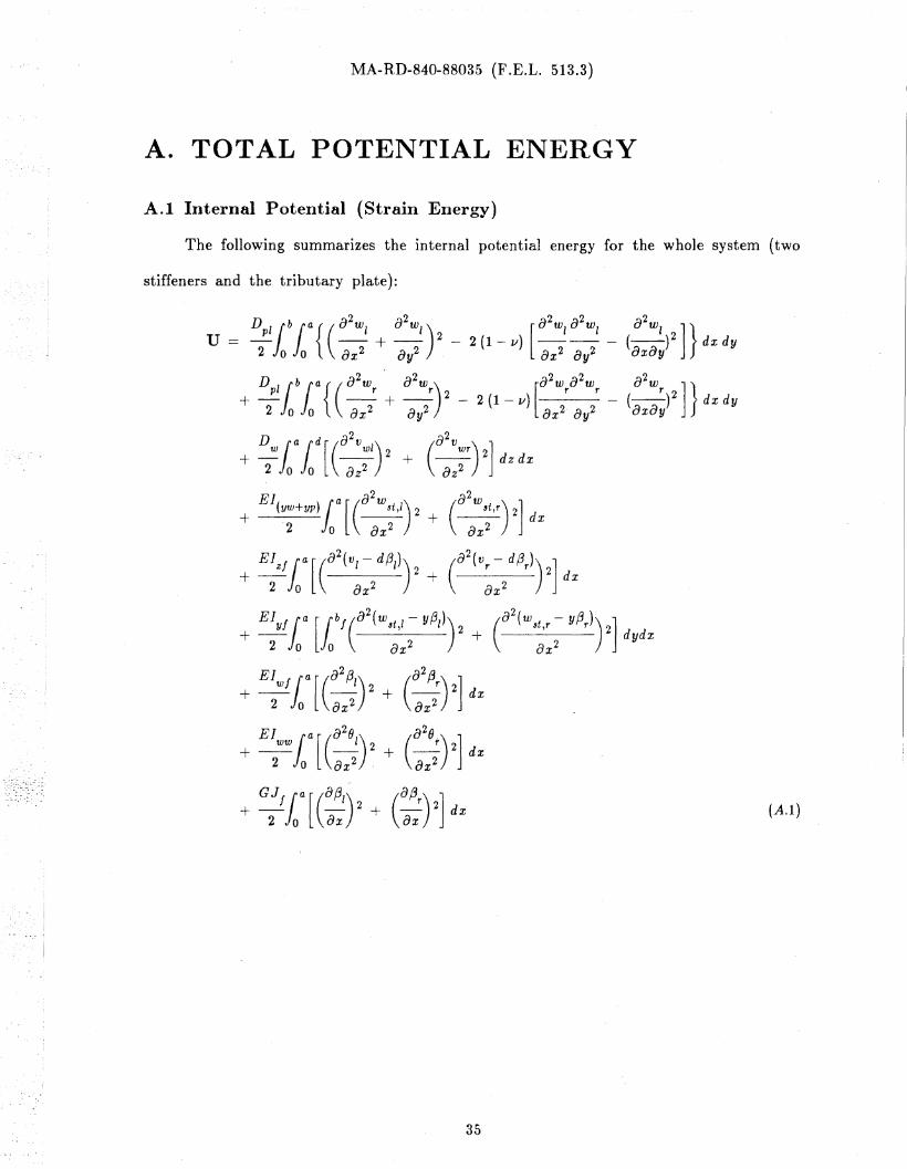
A.I Internal Potential (Strain Ellergy)
The following summarizes the internal potential energy for the whole system (two
stiffeners and the tributary plate):
--
+ G:fia[(:1)2 + (:)2] dx
35
(A.I)
MA-RD-840-88035 (F .E.L. 513.3)
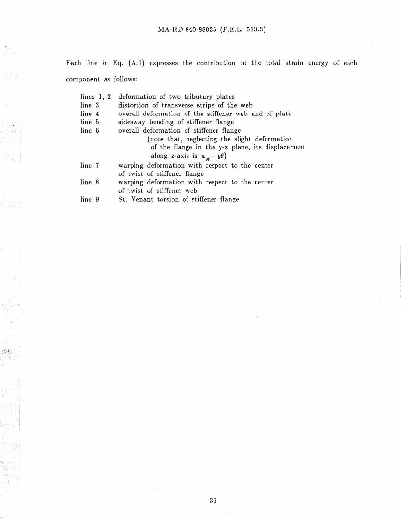
Each line in Eq. (A.I) expresses the contribution to the total strain energy of each
component as follows:
lines 1, 2line 3line 4line 5line 6
line 7
line 8
line 9
deformation of two tributary platesdistortion of transverse 'strips of the weboverall deformation of the stiffener web and of platesidesway bending of stiffener flangeoverall deformation of stiffener flange
(note that, neglecting the slight deformationof the flange in the y-z plane, its displacementalong z-axis is w 8t -0- yO)
warpIng deformation with respect to the centerof twist of stiffener flange\\'arplng deformation with respect to the centerof twist of stiffener webSt. Venant torsion of stiffener flange
36
MA-RD-840-88035 (F.E.L. 513.3)
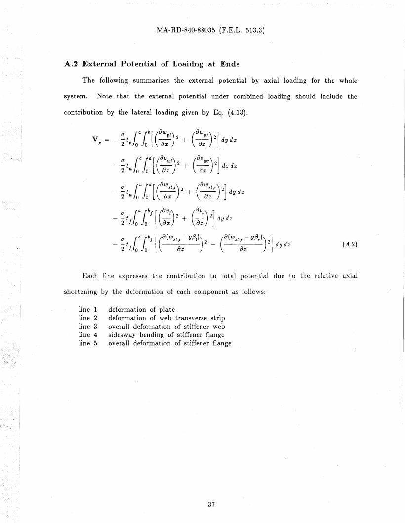
A.2 External Potential of Loaidng at Ends
The following summarizes the external potential by axial loading for the whole
system. Note that the external potential under combined loading should include the
contribution by the lateral loading given by Eq. (4.13).
~ twfaa fad [(0;:/) 2+ (O;;r) 2] dz dx
_ ~twfaafad[ (O;:t,/) 2+ (O::,r) 2] dydx
(J l alb/ [(av1) 2 (av r
) 2]-t - + - dydx2 f 0 0 ax ax
(A.2)
Each line expresses the contribution to total potential due to the relative axjal
shortening by the deformation of each component as follows;
line 1line 2line 3line 4line 5
deformation of platedeformation of \veb transverse stripoverall deformation of stiffener websidesway bending of stiffener flangeoverall deformation of stiffener flange
37
MA-RD-840-88035 (F.E.L. 513.3)
TABLES
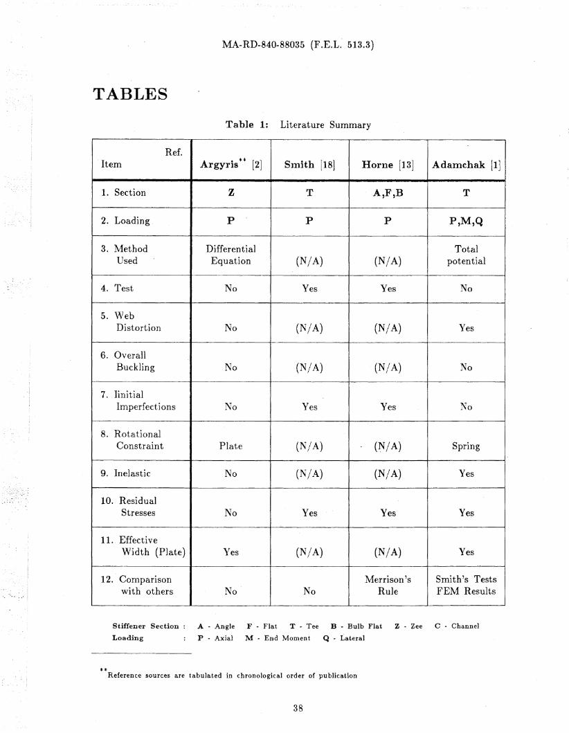
Table 1: Literature Summary
Ref.Item A · ** [2] Slnith [18] Horne [13] Adamchak [1Jrgyrls
1. Section Z T A,F,B T
2. Loading P P P P,M,Q
3. Method Differential TotalUsed Equation (N/A) (N/A) potential
4. Test No Yes Yes No
5. \\7 ebDistortion No (NjA) (N/A) Yes
6. OverallBuckling No (N/A) (N/A) No
7. IinitialImperfections No Yes Yes No
8. R.otationalConstraint Plate (N/A) (~/A) Spring
9. Inelastic No (N/A) (N/A) Yes
10. ResidualStresses No Yes Yes Ye~
11. EffectiveWidth (Plate) Yes (N/A) (N/A) Yes
12. Comparison Merrison's Smith's Testswith others No No Rule FEM Results
Stiffener Section: A - Angle ,F - Flat T .. Tee B .. Bulb Flat Z· Zee C· Channel
Loading P .. Axial M .. End Moment Q .. Lateral
**Reference sources are tabulated in chronological order of publication
38
MA-RD-840-88035 (F.E.L. 513.3)
Table 1 (continued)
Ref.Items Bijlaard [4] V.d. Neut [20] Ostapenko 115] Garncarek 110] Lehmann [14]
1. A,T,F Z A,T Z,T,C A
2. P p P,M,Q P,M Q
Differential Differential Total Total Beam on3. Equation Equation Potential Potential*** Elast. Fdn.
4. No No No No No
5. No Yes Yes Yes Yes
6. No Yes Yes No No
7. No No No No No
8. Spring Spring Spring Spring Spring
9. No No Yes No Yes
10. No No Yes No No
11. No No Yes No No
Adamchak'sG.D. Guideline
Smith's 196812. No No Horne's AISI Spec. No
Stiffener Section: A .. Angle F .. Flat T .. Tee B .. Bulb z .. Zee C .. Channel
Loading P .. Axial M .. End Moment Q .. Lateral
***Finite Difference Method for web element
39
MA-RD-840-88035 (F .E.L. 513.3)
Table 2: Comparison of Computed Results with Van der Neut's Solution
in Elastic Range
(1 I (Jcr Euler
Current V. d. NeutSpecimen air bit d/b Method (Ostapenko)
1 33.0 29. 0.54 0.77 0.78
2 32.5 33.0 0.54 0.74 0.74
3 32.0 39.0 0.54 0.68**** 0.70
Note: The section is modified from the example In \1an der Neut '8 paper
Table 3: Section Properties of Specimens Used in Figures
(..t\Jl dimensions are in inches)
Ref. a ~b t d tw bf t f
Fig. 9 48.0 to 220.0 24.0 0.3 to 0.8 4.0 to 8.0 0.3 3.5 0.4
Fig. 10 72.0 to 192.0 24.0 0.55 6.0 0.3 3.5 0.4
Fig. 13 50.0 to 150.0 25.0 0.33 5.0 0.25 3.0 0.3
Fig. 15 100 25.0 0.33 5.0 0.25 3.0 0.3
Fig. 14 72.0 24.0 0.4 6.0 0.3 3.5 0.35
Note: Parameters, such as,. air, b/t, and d/b, are to be adjustedas shown in each figure.
****Plate in symmetrical mode
40
MA-RD-840-88035 (F.E.L. 513.3)
FIGURES
Tee Flat Bulb-Flat Angle Zee
Symmetrical Asymmetrical
Figure 1: Various Types of Stiffener Section
Figure 2: Angle and Tee Stiffeners (Other Dimensions in Fig. 3)
a
-Ib
'-fi".
b
i
41
MA-RD-840-88035 (F .E.L. 513.3)
r.. I
I
(
d
Figure 3: Geometry of Angle Section
Figure 4: Deformation of Stiffener Web
42
J ey
MA-RD-840-88035 (F.E.L. 513.3)
p ·Ir------------Q ti_t__j~~--L-..---I r r
Figure 5: Unit to be Analyzed and Loading Applied (in positive direction)
43
MA-RD-840-88035 (F .E.L. 513.3)
- -
a. Symmetrical Mode
b. Antisymmetrical Mode
c cH 1 H8
~ ,)_...._-- ;__9_.:]< __-""
-- ,
1----!
--,.
--1------- -L- _
c. Overall Mode
Figure 6: Deformation (Buckling) Modes
44
MA-RD-840-88035 (F.E.L. 513.3)
C3
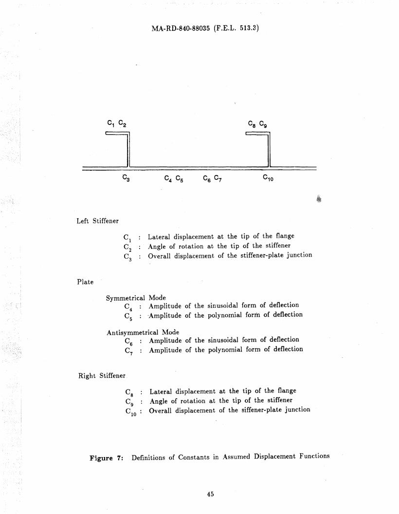
Left Stiffener
C1
Lateral displacement at the tip of the flangeC
2Angle of rotation at the tip of the stiffener
C3
Overall displacement of the stiffener-plate junction
Plate
Symmetrical ModeC4 Amplitude of the sinusoidal form of deflectionCs : -Amplitude of the polynomial form of deflection
Antisymmetrical ModeC
6Amplitude of the sinusoidal form of deflection
C7
: Amplitude of the polynomial form of deflection
Right Stiffener.
Cg Lateral displacement at the tip of the flange
Cg Angle of rotation at the tip of the stiffenerC
IOOverall displacement of the siffener-plate junction
Figure 7: Definitions of Constants In Assumed Displacement Functions
45
MA-RD-840-88035 (F .E.L. 513.3)
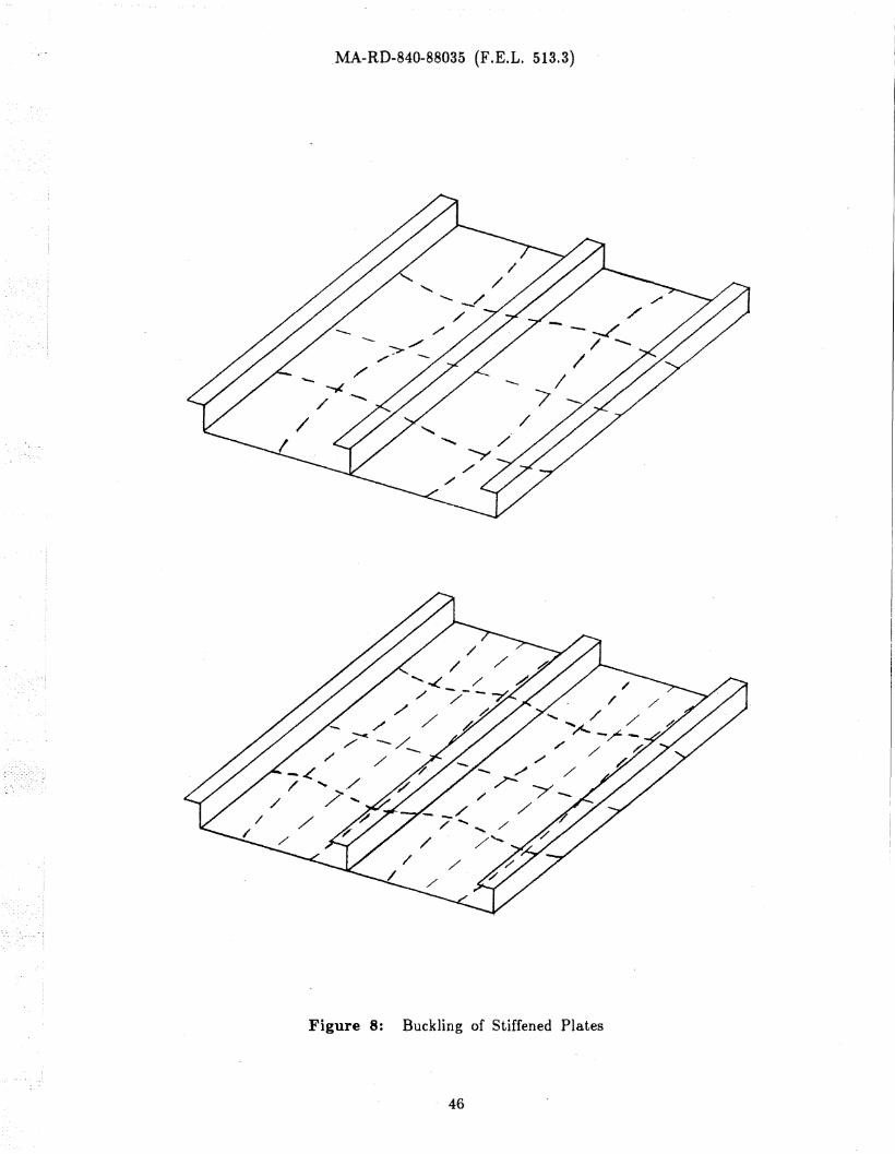
Figure 8: Buckling of Stiffened Plates
46
MA-RD-840-88035 (F.E.L. 513.3)
oof
oo~
o·oco
o·oa.1
o·o~
o·oLO
a·al:'-
o.o~
o.oLC:l
.........
o.oCO
'x,,,,,,,..,..,,.........,.
X
o.ol'-
o.oCO
o.o0)
Q0
• ,..-I
+J• ....-trnQro~~
Q)
ro0::sb.()
Q• ....-t.......~C)
~P=l
Figure 9: Buckling Mode Transition
47
MA-RD-840-88035 (F .E.L. 513.3)
1.4
1.0
*- - '"""*, ...... .....~
"
oo 20 40 60 80 100 air
Figure 10: General Comparison of Buckling Strength for Angle and Tee Stiffener .
Upward loading
Axial loading
Sidesway deflection of stiffener
Vertical deflection due to loads
Figure 11: Stress Distribution under Combined Loading
48
MA-RD-840-88035 (F.E.L. 513.3)
~ I op
+,,
,~-~~-------
OfUI~L--_.l-- ~__-+-_~op+oa
.....
a
Figure 12: Modified Effective Width Concept under Combined Loading
49
MA-RD-840-88035 (F .E.L. 513.3)
~
I
C\2·
o·C\2I
C\l·
o·C\l
_... - .... -_..------- ......
-..........
50
oCY
""CY
"";;I'
,,~;". • ". '* .
"," Q .".,; ...."= ......•..
............ III
'I 1IIi .. ........... ."." . ...... ..- ..... _- - .... _---.- --- -- ............ ......... -
(\J ,. co~ N enoi cD r-:N to CDII n II
~~~'" cd IS
CD.o
Figure 13: Interaction between P and Q Considering the Effect of Slenderness Ratio
MA-RD-840-88035 (F .E.L. 513.3)
Figure 14: Ratio of maximum stresses bet\veen deformed and undeformed sections
for variable axial and lateral loads
o
~
I \
/ \
\\
\
-\ \ -l:,\\ \ \\ \ \
\\ \ \\ -\ \
\ '
\\\
\ /
I, ¥'
~ "4 C? 0?""" ?""" ?"""
I "'ilc<::~---.......----I.....------JJ'--
~
'\tj
51
MA-RD-840-88035 (F.E.L. 513.3)
Figure 15: Interaction between P and Q with Initial Imperfection (air == 58.24)
~·~a'U~
C\2cd ·P-t~
S co ~cd . .S-t 0 0 0 0Q() p...cd '"...... ~
0
~0 C\l...... ·
.......:» IC)
cd~(])
.......:»~ Q ~
.....-t 0..., '0 0 I(.) 0....Q) 0 0 10....,
0(J li .... lO NG)
" " "'-...~ .... ~ ....
tc..!JIi
co..... IE
52
MA-RD-840-88035 (F .E.L. 513.3)
calcaulate thesection properties
-. au..... A ="""7' ()C., ,
increase loading BaVe
= ()C.(P or Q) ,
~J x = {Ci }
"~
generate matrix A
generate matrix B
initialimperfections
solve the set of simultaneousequat~ons Ax. B
repeat untiltolerancesatisfied
calculate stresses in theplate and at both edgesof the flange at mi~·span
effective widthof the plate
repeat untilthe first yieldcriterion is met
check tolerance (0.001) forthe b." and 0edge (stress in the plate)
,~
choose the largest amongthe three stresses
next input
Figure 16: Flow Chart for Computer Program
53
MA-RD-840-88035 (F.E.L. 513.3)
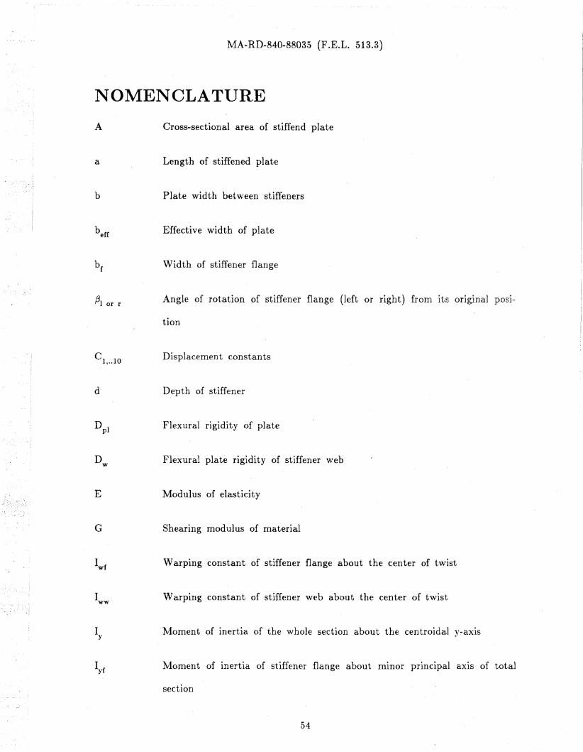
NOMENCLATURE
A
a
b
131 or r
C1, .. 10
d
Dw
E
G
Iy
Cross-sectional area of stiffend plate
Length of stiffened plate
Plate width between stiffeners
Effective width of plate
Width of stiffener flange
Angle of rotation of stiffener fla.nge (left or right) from its original posi
tion
Displacement constants
Depth of stiffener
Flexural rigidity of plate
Flexural plate rigidity of stiffener \\Teb
Modulus of elasticity
Shearing modulus of material
Warping constant of stiffener flange about the center of twist
Warping constant of stiffener web about .the center of twist
Moment of inertia of the whole section about the centroidal y-axis
Moment of inertia of stiffener flange about mInor principal axis of total
sectiQn
54
I (yw+yp)
r
(J
(Jcr
(Je
(JEuler
t
t w
u
v
Ve
MA-RD-840-88035 (F.E.L. 513.3)
Moment .of inertia of plate and stiffener web about mInor principal aXIS
of total section
Moment of inertia of stiffener flange about the centroidal z-axis of stif-
fener section
St. Venant torsional constant of stiffener flange
Radius of gyration of total section about y-aXIS
Applied axial stress (P divided by total area)
Buckling stress of simply supported plate
Edge stress (stress In plate at stiffener-plate junction)
Euler buckling stress
Thickness of flange
Thickness of plate
Thickness of web
Internal potential (strain energy)
Total potential energy
External potential
External' potential due to axial loading P
External potential due to lateral loading Q
Lateral displacement in y-direction at the stiffener tip measured from its
original position (left or right stiffener in unit)55
MA-RD-840-88035 (F .E.L. 51~.3)
v , V I Displacement In y-direction along the stiffener web (left or right)w w or wr
W p ' WI or r
W st,J or st,r
0, 01 or r
Displacement of plate in z-direction (left or right)
Overall displacement of structure at stiffener location In z-direction
Angle of rotation at the stiffener-plate junction (left or right)
56