tutorial on getting started in cadence• start cadence from the terminal by using the command...
TRANSCRIPT

Tutorial on getting started in Cadence
Advanced Analog Circuits Spring 2015
Instructor: Prof. Harish Krishnaswamy TA: Jahnavi Sharma
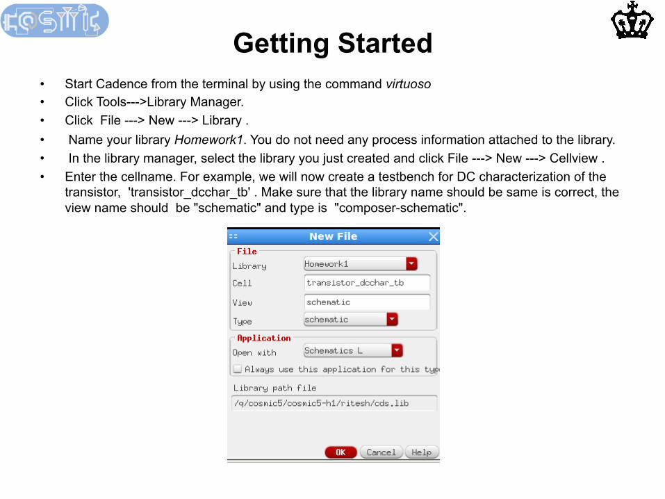
Getting Started • Start Cadence from the terminal by using the command virtuoso • Click Tools--->Library Manager. • Click File ---> New ---> Library . • Name your library Homework1. You do not need any process information attached to the library. • In the library manager, select the library you just created and click File ---> New ---> Cellview . • Enter the cellname. For example, we will now create a testbench for DC characterization of the
transistor, 'transistor_dcchar_tb' . Make sure that the library name should be same is correct, the view name should be "schematic" and type is "composer-schematic".

• In the new schematic composer window, we will place the nmos. In the top menu, Create -> Instance , or just press 'i' from the keyboard,. Click "Browse" next to library name to open the Library browser. Choose "analogLib" for library , "nmos4" for the cell and "symbol" for the view.
• The model name is "nch". Do NOT include the library name in this line.
• Enter the parameters of the nmos, here we have a width of 3um and length 180 nm.
Creating schematics

• Similarly, from analogLib you can instantiate voltage sources using the "vdc" component.
• Note that we have entered a variable name "Vds" for the DC voltage value. This is because we will be doing a DC sweep for the drain and gate voltages as we characterize the device.
• Instantiate another voltage source with voltage "Vgs".
• Instantiate a ground node using the "gnd" cell from analogLib.
• Although, we don't need them for this example, you can instantiate capacitors using "cap", resistors with "res" and inductors with "ind".
Creating schematics

• Once all the components are instantiated, connect them appropriately, using the Create-> Wire command from the top menu in the schematic composer window. You can also just press 'w' .
• You can label the wires by pressing 'l' key. (This is the small l for lamb). Enter the name and drag and place it on the desired net.
• Your schematic should now look like • Save your schematic from the top menu in the schematic composer window by clicking File->
Check and Save.
Creating schematics

• From the top menu in the schematic composer, select Launch->ADE L. • First we will assign nominal values to the variables in our schematic. For this, in the ADE window,
select Variables -> Edit. As you can typically have a lot of variables, and don't accidentally want to miss adding any of them, click on the "Copy From" button. This carries over all the variables in the schematic to your ADE window.
• Now click on a variable and change it's value. For this, click on the variable, enter the desired value and click "Change". I have nominally assigned them both to 1.2 V but we will be sweeping these variables.
Running a simulation: Variables

• The library name should be instantiated from ADE-L through the Setup/Model library menu. Use the 'tt' process corner for homeworks.
• Other devices, can be instantiated by using the appropriate sections as listed in the following table:
Running a simulation: Model Library
Device Model name Section
1.8V pMOS, nMOS regular devices nch, pch tt
3.3V pMOS, nMOS regular devices nch3, pch3 tt_3v
1.8V zero Vt nMOS nanch tt_na
3.3V zero Vt nMOS nanch3 tt_3vna
1.8V medium Vt nMOS mench tt_m
3.3V medium Vt nMOS mench3 tt_3m

• By default, Spectre only saves the currents flowing through voltage sources. • To monitor the current in a branch add a 0 V voltage source (“vdc” component ) in that branch. • You can also ask Spectre to save all the currents from the ADE-L menu by selecting Outputs-> Save all and then checking Select Device Currents -> all. • If you have a very large schematic saving all the currents can take up too much disk space during simulation.
Running a simulation: Saving currents

Now let us setup a simulation. We will sweep the drain voltage for a fixed gate voltage. Then we will sweep the gate voltage as well.
Essentially, we want to generate the device I-V characteristics for different gate and drain voltages.
• In the ADE window , click Choose -> Analysis. • Configure your window as shown below to
perform a DC sweep. We will sweep drain voltage Vds for a fixed gate voltage Vgs of 1.2 V.
(a) Check "Save DC Operating Point" (b) Check "Design Variable" and from the "Select Design Variable" menu choose "Vds". (c) In the "Sweep Range", sweep from 0 to 1.2 V. In "Sweep Type", choose "Linear" anf enter a "Step Size" of 0.1 V. Note that sometimes you may want to choose "Logarithmic" when you are sweeping over very large ranges.
Click "OK".
• Now we can run the analysis. From the ADE
window choose Simulation -> Netlist and Run. A simulation log should open up where you will see the simulations running.
Running a simulation: DC Sweep analysis

To plot the results from your sweep analysis, from the ADE-L window select Tools-> Calculator. In the calculator window, select “is” and click on the negative terminal of the DC voltage source (instance name “V0” in this example)at the drain node. The entry IS(“/V0/MINUS”) should appear as shown below in the calculator window. Click the plot button circled in the picture. This will plot the DC current from the swept analysis.
Running a simulation: Results from swept DC analysis

Running a simulation: Results from swept DC analysis

• For homework 1 you will need to run this DC sweep with a parametric sweep on the variable "Vgs" . This enables you to sweep "Vds" through the DC sweep analysis we just set up for different gate voltages. This way you can generate, for example, Ids vs Vds for different Vgs.
• From the ADE menu, choose Tools -> Parametric Analysis. • In the parametric analysis window, click on "Choose Variable" and select Vgs and enter the
sweep ranges as shown below. Check "Sweep", enter the "From" and "To" values. Finally, select the "Step Mode" as "Linear" and enter the "Step Size" of 0.1 V.
• Select Analysis -> “Start Selected Sweep”. • This will now perform the DC sweep discussed previously for each Vgs value.
Running a simulation: Parametric analysis

Running a simulation: Results from parametric swept DC analysis
To plot the results from your parametric sweep analysis, follow the same steps as those for plotting the results from the swept DC analysis. You can plot the results in a new graph window by selecting New Window from the drop-down menu in the Calculator window

Running a simulation: Results from parametric swept DC analysis