tutorial for vector nti advance™ 9 - friedrich miescheri · this version of the vector nti...
TRANSCRIPT

©2003 InforMax™: Invitrogen™ life science software Confidential
Tutorial for Vector NTI Advance™ 9.0
Novartis – Advanced Users Course
©2003 InforMax™: Invitrogen™ life science software Confidential
2
Vector NTI Advance™ 9.0 Training Manual Published by: US Headquarters 7305 Executive Way Frederick, MD 21704 www.informaxinc.com
Copyright © 2003 InforMax™. All rights reserved. This book contains proprietary information of InforMax™. No part of this document, including design, cover design, and icons, may be reproduced or transmitted in any form, by any means (electronic, photocopying, recording, or otherwise) without prior written agreement from InforMax™. The software described in this document is furnished under a license agreement. InforMax™ and its licensors retain all ownership rights to the software programs offered by InforMax™ and related documentation. Use of the software and related documentation is governed by the license agreement accompanying the software and applicable copyright law. Vector NTI Advance™ is a registered trademark of InforMax™ in the United States and other countries. Logos of InforMax™ are also trademarks registered in the United States and may be registered in other countries. Other product and brand names are trademarks of their respective owners. Generated in the U.K. InforMax™ reserves the right to make changes, without notice, both to this publication and to the product it describes. Information concerning products not manufactured or distributed by InforMax™ is provided without warranty or representation of any kind, and InforMax™ will not be liable for any damages. This version of the Vector NTI Advance™ Training Manual was published in November 2003
InforMax™: Invitrogen™ life science software
US Headquarters European Office 7305 Executive Way The Magdalen Centre Frederick, Oxford Science Park
MD 21704 Oxford, OX4 4GA United States United Kingdom
www.informaxinc.com
Technical Support Contacts: Tel: 877-357-3114 (Toll free within the US); +1 240-747-4240 (International) +44 1865 784591 (Europe) U.S. Technical Support Email: [email protected] European Technical Support Email: [email protected] Internet: http://www.informaxinc.com/support
©2003 InforMax™: Invitrogen™ life science software Confidential
3
Virtual Cloning................................................................................................................................................. 5
Construction Mode of Cloning – Advanced Example..................................................................................... 5 • Parents/Child Relationships................................................................................................................ 6 • Report Generation .............................................................................................................................. 6
Gateway® Cloning ........................................................................................................................................ 6 • Creating an Entry Clone via PCR ....................................................................................................... 6 • Creating an Expression Clone ............................................................................................................ 8 • Creating an Entry Clone from an Expression Clone and a pDONR™ Vector.................................... 10 • Creating a Novel Destination Vector................................................................................................. 10
Design Mode of Cloning .............................................................................................................................. 11 • Creating an Enzyme Subset ............................................................................................................. 11 • Designing a Cloning Strategy ........................................................................................................... 11 • Creating a Clone with the Insert in the Reverse Orientation ............................................................. 13
Virtual Gels .................................................................................................................................................... 14 • Creating a New Gel .......................................................................................................................... 14 • Creating a Gel Sample ..................................................................................................................... 14 • Creating a Gel Marker ...................................................................................................................... 14 • Running the Gel................................................................................................................................ 14 • Estimating Separation Time.............................................................................................................. 14 • Partial Digests .................................................................................................................................. 15 • Saving Gel Documents ..................................................................................................................... 15
Importing Sequences from Biobench........................................................................................................... 16 AlignX® - Multiple Sequence Alignment ..................................................................................................... 17
• Launching AlignX®........................................................................................................................... 17 • Plots Setup ....................................................................................................................................... 18 • Viewing Additional Analyses in the Graphics Pane........................................................................... 18 • Changing the Alignment Parameters ................................................................................................ 18 • Changing the Alignment Display Setup............................................................................................. 19 • Editing an Alignment......................................................................................................................... 19 • Realigning a Selected Area of the Alignment.................................................................................... 20 • Finding a Sequence.......................................................................................................................... 20 • Finding a Feature ............................................................................................................................. 20 • Displaying a Feature in the Alignment Pane ..................................................................................... 20 • Changing the Molecule Order in the Alignment Pane ....................................................................... 21 • Publishing the Alignment .................................................................................................................. 21 • Opening the Consensus Sequence in Vector NTI®.......................................................................... 21 • Broadcasting a Region to Vector NTI®............................................................................................. 21 • Saving an Alignment......................................................................................................................... 22 • Dot Matrix Analysis........................................................................................................................... 22 • Similarity Table Analysis................................................................................................................... 22
ContigExpress®............................................................................................................................................. 23 • Selecting Plasmid Regions for Vector Trimming............................................................................... 23 • Adding New Files to a Project........................................................................................................... 23 • End Trimming By Sequence Characteristics..................................................................................... 24 • Trimming for Vector Contamination .................................................................................................. 24 • Calling Secondary Peaks.................................................................................................................. 25 • Saving a Project ............................................................................................................................... 25 • Viewing and Manually Editing Sequences ........................................................................................ 25 • Finding Sequences and Open Reading Frames in a Fragment ........................................................ 26 • Assembly Setup................................................................................................................................ 26 • Assembling Contigs.......................................................................................................................... 27 • Opening the Contig Viewer............................................................................................................... 28 • Viewing the Coverage of a Contig .................................................................................................... 29 • Open Reading Frame Searches and Translations ............................................................................ 29 • Reassembling Fragments................................................................................................................. 29 • Moving Fragments............................................................................................................................ 29
©2003 InforMax™: Invitrogen™ life science software Confidential
4
• Editing the Contig ............................................................................................................................. 30 • Changing Viewing Options ............................................................................................................... 30 • Finding Fragments and Sequences .................................................................................................. 31 • Editing Fragment and Contig Data.................................................................................................... 31 • Exporting the Contig Consensus Sequence to Vector NTI®............................................................. 31
Batch Import of Oligos .................................................................................................................................. 32 • Batch Import of Oligonucleotides ...................................................................................................... 32
©2003 InforMax™: Invitrogen™ life science software Confidential
5
Virtual Cloning Construction Mode of Cloning – Advanced Example - Dealing with incompatible termini
Open pUC19 from the Vector NTI® Explorer
Select 5’ terminus = BamHI ; 3’ terminus = SmaI
Choose Cloning | Add Fragment to Goal List Click Finish then Add to List
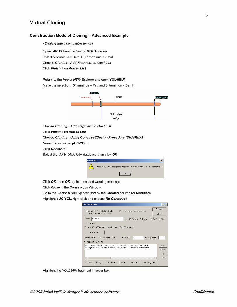
Return to the Vector NTI® Explorer and open YOL056W
Make the selection: 5’ terminus = PstI and 3’ terminus = BamHI
Choose Cloning | Add Fragment to Goal List Click Finish then Add to List Choose Cloning | Using Construct/Design Procedure (DNA/RNA) Name the molecule pUC-YOL Click Construct Select the MAIN DNA/RNA database then click OK
Click OK, then OK again at second warning message
Click Close in the Construction Window
Go to the Vector NTI® Explorer, sort by the Created column (or Modified)
Highlight pUC-YOL, right-click and choose Re-Construct
Highlight the YOL056W fragment in lower box
©2003 InforMax™: Invitrogen™ life science software Confidential
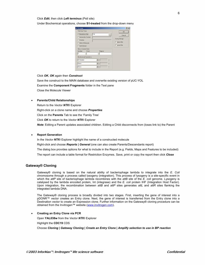
6Click Edit, then click Left terminus (PstI site)
Under Biochemical operations, choose S1-treated from the drop-down menu
Click OK, OK again then Construct Save the construct to the MAIN database and overwrite existing version of pUC-YOL
Examine the Component Fragments folder in the Text pane
Close the Molecule Viewer
• Parents/Child Relationships Return to the Vector NTI® Explorer
Right-click on a clone name and choose Properties
Click on the Parents Tab to see the ‘Family Tree’
Click OK to return to the Vector NTI® Explorer
Note: Editing a Parent updates associated children. Editing a Child disconnects from (loses link to) the Parent
• Report Generation In the Vector NTI® Explorer highlight the name of a constructed molecule
Right-click and choose Reports | General (one can also create Parents/Descendants report)
The dialog box provides options for what to include in the Report (e.g. Fields, Maps and Features to be included)
The report can include a table format for Restriction Enzymes. Save, print or copy the report then click Close
Gateway® Cloning
Gateway® cloning is based on the natural ability of bacteriophage lambda to integrate into the E. Coli chromosome through a process called lysogeny (integration). This process of lysogeny is a site-specific event in which the attP site of bacteriophage lambda recombines with the attB site of the E. coli genome. Lysogeny is catalysed by the lambda encoded protein, Int (integrase) and the E. coli protein IHF (Integration Host Factor). Upon integration, the recombination between attB and attP sites generates attL and attR sites flanking the integrated lambda DNA.
The Gateway® cloning process is broadly divided into two stages. First, inserting the gene of interest into a pDONR™ vector creates an Entry clone. Next, the gene of interest is transferred from the Entry clone into a Destination vector to create an Expression clone. Further information on the Gateway® cloning procedure can be obtained from the Invitrogen™ website (www.invitrogen.com).
• Creating an Entry Clone via PCR Open YAL038w from the Vector NTI® Explorer
Highlight the CDC19 CDS Choose Cloning | Gateway Cloning | Create an Entry Clone | Amplify selection to use in BP reaction
©2003 InforMax™: Invitrogen™ life science software Confidential
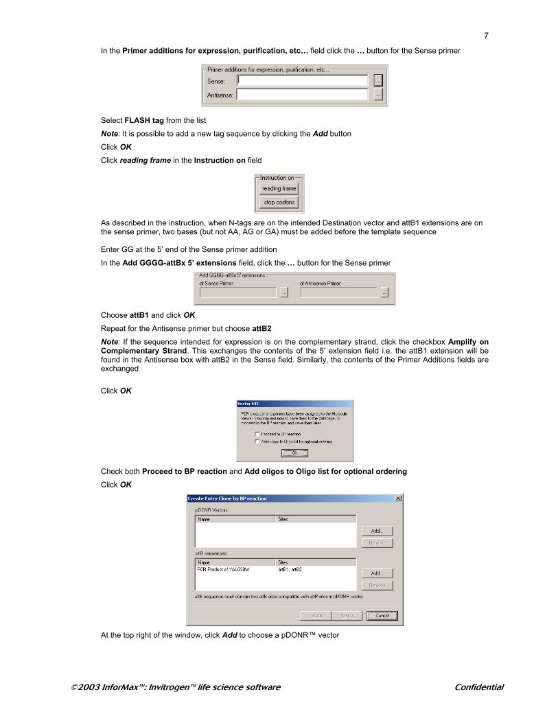
7In the Primer additions for expression, purification, etc… field click the … button for the Sense primer
Select FLASH tag from the list
Note: It is possible to add a new tag sequence by clicking the Add button
Click OK
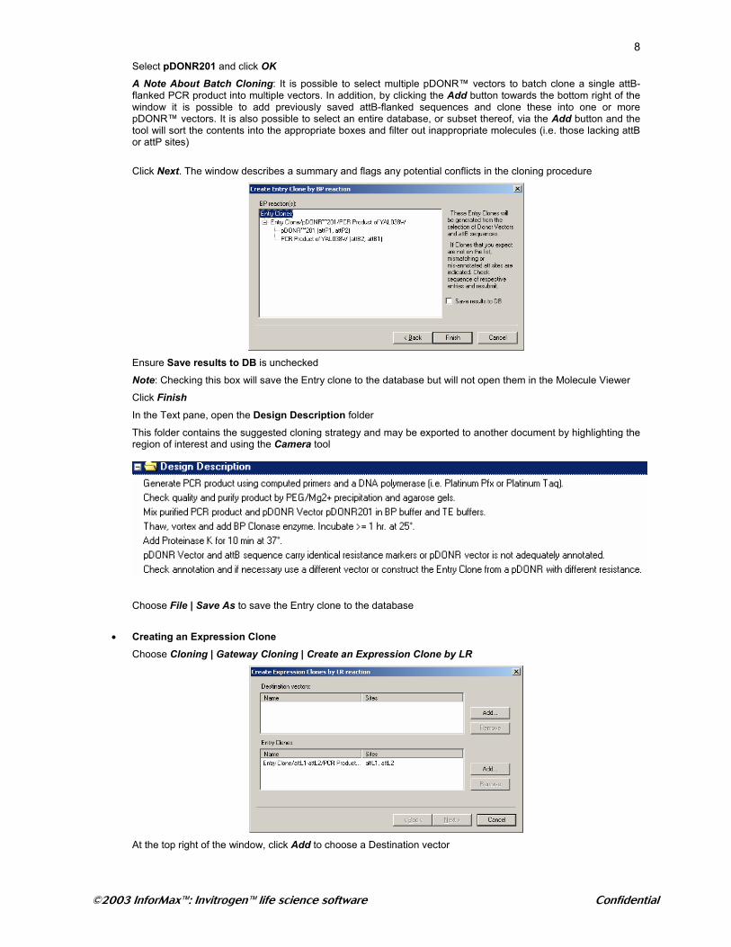
Click reading frame in the Instruction on field
As described in the instruction, when N-tags are on the intended Destination vector and attB1 extensions are on the sense primer, two bases (but not AA, AG or GA) must be added before the template sequence Enter GG at the 5’ end of the Sense primer addition
In the Add GGGG-attBx 5’ extensions field, click the … button for the Sense primer
Choose attB1 and click OK Repeat for the Antisense primer but choose attB2
Note: If the sequence intended for expression is on the complementary strand, click the checkbox Amplify on Complementary Strand. This exchanges the contents of the 5’ extension field i.e. the attB1 extension will be found in the Antisense box with attB2 in the Sense field. Similarly, the contents of the Primer Additions fields are exchanged
Click OK
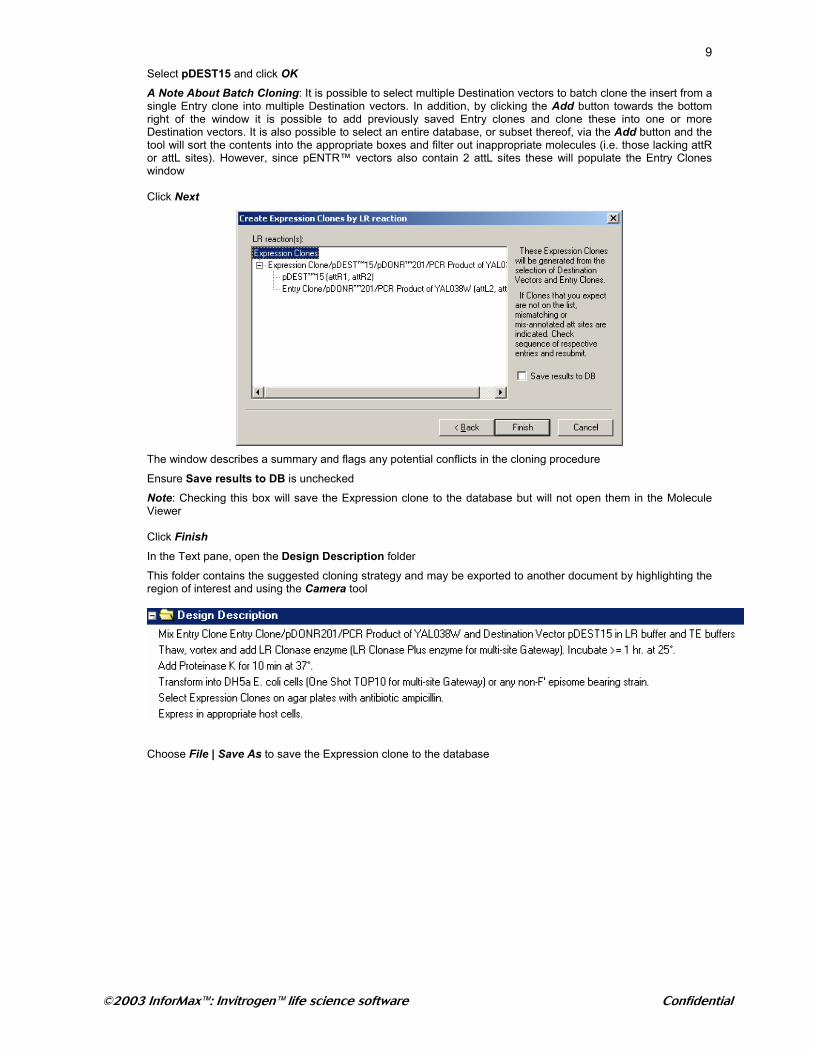
Check both Proceed to BP reaction and Add oligos to Oligo list for optional ordering
Click OK
At the top right of the window, click Add to choose a pDONR™ vector
©2003 InforMax™: Invitrogen™ life science software Confidential
8Select pDONR201 and click OK
A Note About Batch Cloning: It is possible to select multiple pDONR™ vectors to batch clone a single attB-flanked PCR product into multiple vectors. In addition, by clicking the Add button towards the bottom right of the window it is possible to add previously saved attB-flanked sequences and clone these into one or more pDONR™ vectors. It is also possible to select an entire database, or subset thereof, via the Add button and the tool will sort the contents into the appropriate boxes and filter out inappropriate molecules (i.e. those lacking attB or attP sites)
Click Next. The window describes a summary and flags any potential conflicts in the cloning procedure
Ensure Save results to DB is unchecked
Note: Checking this box will save the Entry clone to the database but will not open them in the Molecule Viewer
Click Finish In the Text pane, open the Design Description folder
This folder contains the suggested cloning strategy and may be exported to another document by highlighting the region of interest and using the Camera tool
Choose File | Save As to save the Entry clone to the database
• Creating an Expression Clone
Choose Cloning | Gateway Cloning | Create an Expression Clone by LR
At the top right of the window, click Add to choose a Destination vector
©2003 InforMax™: Invitrogen™ life science software Confidential
9Select pDEST15 and click OK
A Note About Batch Cloning: It is possible to select multiple Destination vectors to batch clone the insert from a single Entry clone into multiple Destination vectors. In addition, by clicking the Add button towards the bottom right of the window it is possible to add previously saved Entry clones and clone these into one or more Destination vectors. It is also possible to select an entire database, or subset thereof, via the Add button and the tool will sort the contents into the appropriate boxes and filter out inappropriate molecules (i.e. those lacking attR or attL sites). However, since pENTR™ vectors also contain 2 attL sites these will populate the Entry Clones window Click Next
The window describes a summary and flags any potential conflicts in the cloning procedure
Ensure Save results to DB is unchecked
Note: Checking this box will save the Expression clone to the database but will not open them in the Molecule Viewer Click Finish In the Text pane, open the Design Description folder
This folder contains the suggested cloning strategy and may be exported to another document by highlighting the region of interest and using the Camera tool
Choose File | Save As to save the Expression clone to the database
©2003 InforMax™: Invitrogen™ life science software Confidential
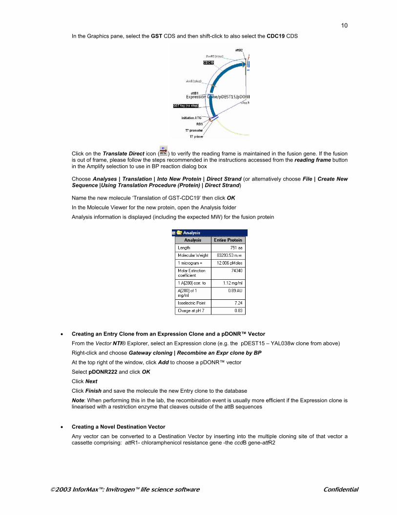
10In the Graphics pane, select the GST CDS and then shift-click to also select the CDC19 CDS
Click on the Translate Direct icon ( ) to verify the reading frame is maintained in the fusion gene. If the fusion is out of frame, please follow the steps recommended in the instructions accessed from the reading frame button in the Amplify selection to use in BP reaction dialog box Choose Analyses | Translation | Into New Protein | Direct Strand (or alternatively choose File | Create New Sequence |Using Translation Procedure (Protein) | Direct Strand) Name the new molecule ‘Translation of GST-CDC19’ then click OK
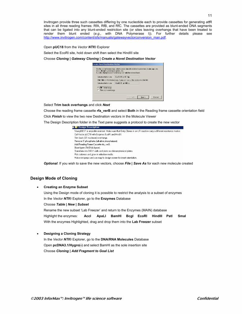
In the Molecule Viewer for the new protein, open the Analysis folder
Analysis information is displayed (including the expected MW) for the fusion protein
• Creating an Entry Clone from an Expression Clone and a pDONR™ Vector From the Vector NTI® Explorer, select an Expression clone (e.g. the pDEST15 – YAL038w clone from above)
Right-click and choose Gateway cloning | Recombine an Expr clone by BP
At the top right of the window, click Add to choose a pDONR™ vector
Select pDONR222 and click OK
Click Next Click Finish and save the molecule the new Entry clone to the database
Note: When performing this in the lab, the recombination event is usually more efficient if the Expression clone is linearised with a restriction enzyme that cleaves outside of the attB sequences
• Creating a Novel Destination Vector
Any vector can be converted to a Destination Vector by inserting into the multiple cloning site of that vector a cassette comprising: attR1- chloramphenicol resistance gene -the ccdB gene-attR2
©2003 InforMax™: Invitrogen™ life science software Confidential
11Invitrogen provide three such cassettes differing by one nucleotide each to provide cassettes for generating attR sites in all three reading frames: RfA, RfB, and RfC. The cassettes are provided as blunt-ended DNA segments that can be ligated into any blunt-ended restriction site (or sites leaving overhangs that have been treated to render them blunt ended (e.g., with DNA Polymerase I)). For further details please see http://www.invitrogen.com/content/sfs/manuals/gatewayvectorconversion_man.pdf.
Open pUC18 from the Vector NTI® Explorer
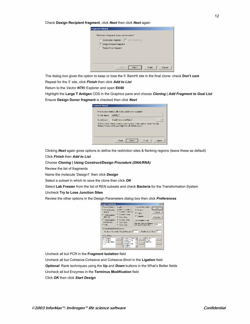
Select the EcoRI site, hold down shift then select the HindIII site Choose Cloning | Gateway Cloning | Create a Novel Destination Vector
Select Trim back overhangs and click Next Choose the reading frame cassette rfa_verB and select Both in the Reading frame cassette orientation field
Click Finish to view the two new Destination vectors in the Molecule Viewer
The Design Description folder in the Text pane suggests a protocol to create the new vector
Optional: If you wish to save the new vectors, choose File | Save As for each new molecule created
Design Mode of Cloning
• Creating an Enzyme Subset Using the Design mode of cloning it is possible to restrict the analysis to a subset of enzymes
In the Vector NTI® Explorer, go to the Enzymes Database
Choose Table | New | Subset Rename the new subset ‘Lab Freezer’ and return to the Enzymes (MAIN) database
Highlight the enzymes: AccI ApaLI BamHI BcgI EcoRI HindIII PstI SmaI With the enzymes Highlighted, drag and drop them into the Lab Freezer subset
• Designing a Cloning Strategy In the Vector NTI® Explorer, go to the DNA/RNA Molecules Database
Open pcDNA3.1/Hygro(-) and select BamHI as the sole insertion site
Choose Cloning | Add Fragment to Goal List
©2003 InforMax™: Invitrogen™ life science software Confidential
12Check Design Recipient fragment, click Next then click Next again
The dialog box gives the option to keep or lose the 5’ BamHI site in the final clone- check Don’t care
Repeat for the 3’ site, click Finish then click Add to List Return to the Vector NTI® Explorer and open SV40
Highlight the Large T Antigen CDS in the Graphics pane and choose Cloning | Add Fragment to Goal List Ensure Design Donor fragment is checked then click Next
Clicking Next again gives options to define the restriction sites & flanking regions (leave these as default)
Click Finish then Add to List Choose Cloning | Using Construct/Design Procedure (DNA/RNA) Review the list of fragments
Name the molecule ‘Design1’ then click Design
Select a subset in which to save the clone then click OK
Select Lab Freezer from the list of REN subsets and check Bacteria for the Transformation System
Uncheck Try to Lose Junction Sites
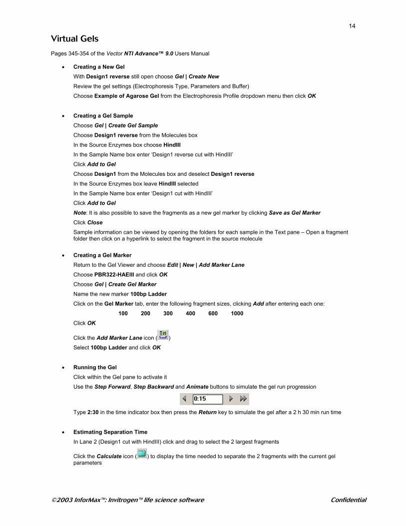
Review the other options in the Design Parameters dialog box then click Preferences
Uncheck all but PCR in the Fragment Isolation field
Uncheck all but Cohesive-Cohesive and Cohesive-Short in the Ligation field
Optional: Rank techniques using the Up and Down buttons in the What’s Better fields
Uncheck all but Enzymes in the Terminus Modification field
Click OK then click Start Design

©2003 InforMax™: Invitrogen™ life science software Confidential
13Examine the resultant molecule and the Design Description folder in the Text pane
Notice that a method for distinguishing clone orientations is to digest with HindIII
• Creating a Clone with the Insert in the Reverse Orientation Choose File | Molecule Operations | Advanced (DNA/RNA) | Design
Click Yes when warned to continue editing
Change the name to ‘Design1 reverse’
Highlight the SV40 fragment in the Component Fragments list and click Edit Check the box next to Inverted
Click OK then click Design
Select a subset in which to save the clone then click OK
Choose Bacteria as the Transformation System then click Start Design
Note: It may be necessary to select the new clone from the Window menu
©2003 InforMax™: Invitrogen™ life science software Confidential
14
Virtual Gels Pages 345-354 of the Vector NTI Advance™ 9.0 Users Manual
• Creating a New Gel With Design1 reverse still open choose Gel | Create New
Review the gel settings (Electrophoresis Type, Parameters and Buffer)
Choose Example of Agarose Gel from the Electrophoresis Profile dropdown menu then click OK
• Creating a Gel Sample Choose Gel | Create Gel Sample
Choose Design1 reverse from the Molecules box
In the Source Enzymes box choose HindIII In the Sample Name box enter ‘Design1 reverse cut with HindIII’
Click Add to Gel Choose Design1 from the Molecules box and deselect Design1 reverse
In the Source Enzymes box leave HindIII selected
In the Sample Name box enter ‘Design1 cut with HindIII’
Click Add to Gel Note: It is also possible to save the fragments as a new gel marker by clicking Save as Gel Marker Click Close Sample information can be viewed by opening the folders for each sample in the Text pane – Open a fragment folder then click on a hyperlink to select the fragment in the source molecule
• Creating a Gel Marker Return to the Gel Viewer and choose Edit | New | Add Marker Lane
Choose PBR322-HAEIII and click OK
Choose Gel | Create Gel Marker Name the new marker 100bp Ladder Click on the Gel Marker tab, enter the following fragment sizes, clicking Add after entering each one:
100 200 300 400 600 1000 Click OK
Click the Add Marker Lane icon ( )
Select 100bp Ladder and click OK
• Running the Gel Click within the Gel pane to activate it
Use the Step Forward, Step Backward and Animate buttons to simulate the gel run progression
Type 2:30 in the time indicator box then press the Return key to simulate the gel after a 2 h 30 min run time
• Estimating Separation Time In Lane 2 (Design1 cut with HindIII) click and drag to select the 2 largest fragments
Click the Calculate icon ( ) to display the time needed to separate the 2 fragments with the current gel parameters
©2003 InforMax™: Invitrogen™ life science software Confidential
15
• Partial Digests Choose Gel | Create New
Click OK in the gel Setup dialog box
Choose Gel | Create Gel Sample
Select pcDNA3.1(+) from the Molecules box
In the Source Enzymes box choose AccI In the Sample Name box enter ‘pcDNA3.1(+) cut with AccI’
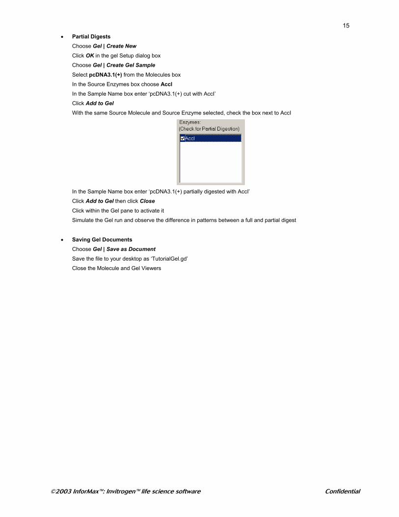
Click Add to Gel With the same Source Molecule and Source Enzyme selected, check the box next to AccI
In the Sample Name box enter ‘pcDNA3.1(+) partially digested with AccI’
Click Add to Gel then click Close
Click within the Gel pane to activate it
Simulate the Gel run and observe the difference in patterns between a full and partial digest
• Saving Gel Documents Choose Gel | Save as Document Save the file to your desktop as ‘TutorialGel.gd’
Close the Molecule and Gel Viewers
©2003 InforMax™: Invitrogen™ life science software Confidential
16
Importing Sequences from Biobench Go to Biobench (http://biobench2.eu.novartis.net/)
Choose Database > SRS
When prompted, provide your Research Applications (Oracle) password (e.g. the one you use for PlasNova)
In the SRS window, choose the second tab Select Databanks
Check the box for the database of interest (e.g. SWISSPROT)
Type a keyword in the 'Quick search' field (e.g. 5H1A)
Click Quick search
Check the boxes of results of interest e.g. the 4 proteins for fugru, mouse, rat, human (e.g. SWISSPROT:5H1A_FUGRU,
SWISSPROT:5H1A_MOUSE, SWISSPROT:5H1A_RAT, SWISSPROT:5H1A_HUMAN)
In the left hand side of the window, there is a 'Result options' box, choose Save results by clicking on the SAVE button.
This opens a Save Options window
Choose 'output to' TEXT
Choose 'save as' ASCII text/table and in the 'save with view' choose from the pull down list *complete entries*
Click on the SAVE button
A file download window opens, choose to Save to Computer In the Save As dialogue box, choose a location (e.g. your desktop) and provide a file name (e.g. '5h1a.txt')
Now you can drag and drop this file into the Vector NTI™ Explorer window

©2003 InforMax™: Invitrogen™ life science software Confidential
17
AlignX® - Multiple Sequence Alignment
Pages 369-393 of the Vector NTI Advance™ 9.0 Users Manual
• Launching AlignX® Go to the Vector NTI® Explorer and highlight the following molecules from the Protein database:
5H1A_FUGRU 5H1A_HUMAN 5H1A_MOUSE 5H1A_RAT
Right-click and choose Align | AlignX – Align Selected Molecules
The Text pane is the only one of the 4 panes that is populated and contains information for each of the molecules imported into AlignX®
Note: Molecule names may be edited by right-clicking on the name and choosing Rename Molecule
Highlight all four molecules in the Text pane then choose Align | Align Selected Sequences
AlignX® uses the CLUSTAL W algorithm. CLUSTAL W tries to align the sequences as they are presented to it – it does not reverse sequences as a Contig Assembly algorithm would For more information on CLUSTALW see: Nucleic Acid Research 22 (22) p4673-4680 (1994)
Once the CLUSTALW algorithm is finished, the remaining 3 panes become populated:
Guide Tree Pane: There must be 4 or more sequences aligned to generate a tree
5H1A_FUGRU (0.2312)5H1A_HUMAN (0.0586)
5H1A_MOUSE (0.0328)5H1A_RAT (0.0289)
The values displayed on the Guide Tree are related to the degree of divergence between the sequences
The CLUSTALW guide tree can be saved as a log (*.ph) file, which be imported into other *.ph format applications (e.g.: PHYLIP) by right-clicking on the tree and choosing Export Guide Tree Graphics Pane: (three graphs)
Similarity Graph (upper graph)
Specific values (between 0 and 1) are assigned to each residue at a given position in the alignment depending on whether the residue is identical (1), similar (0.5) or weakly similar (0.2)to the corresponding residue in the consensus sequence. The value for each position is the sum of the scores for each residue at a given position divided by the number of sequences in the alignment
©2003 InforMax™: Invitrogen™ life science software Confidential
18
Absolute Complexity Graph (center graph)
Calculated as a sum of all pairwise residue substitution scores (taken from the residue substitution matrix used to calculate the alignment) at a given alignment position divided by the number of sequences in the alignment. Also known as ‘Profile of the Multiple Alignment’
Absolute Complexity (Pairwise Alignment) Graph (lower graph)
Calculated as for the center graph but for a selected molecule (selected in the text, phylogenetic tree or alignment pane) relative to the consensus sequence Alignment Pane: Displays aligned sequences and the resulting consensus sequence. The last row in the pane consists of the consensus. The status bar displays the % of similar and identical residues for the entire alignment or for a selected region of the alignment. For alignments of 2 or more sequences, when the mouse cursor is pointed to any column in the alignment a popup label shows the & of similar and identical residues at that position Selection of a region of the alignment in either the alignment pane or the graphics pane is reflected in the other pane
• Plots Setup Right-click on one of the plots and choose Plot Setup, change the window size and datagram characteristics then click OK
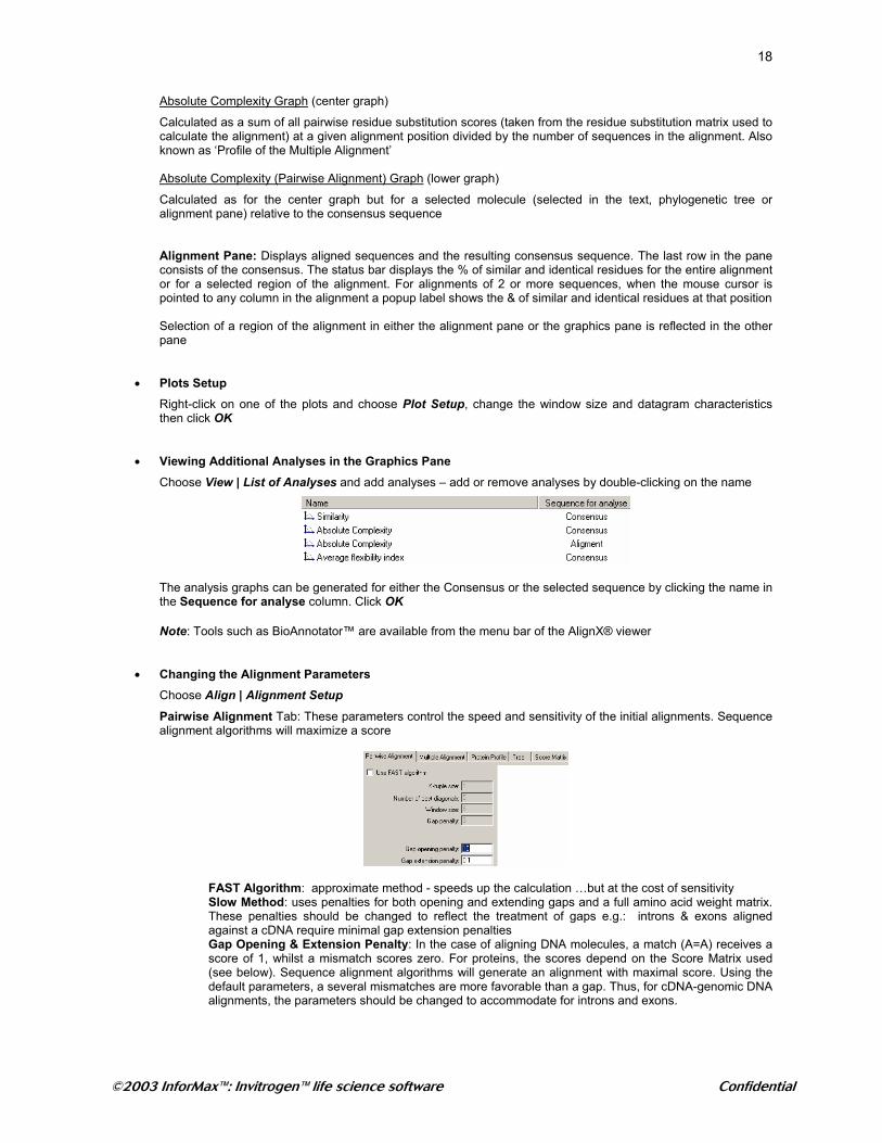
• Viewing Additional Analyses in the Graphics Pane Choose View | List of Analyses and add analyses – add or remove analyses by double-clicking on the name
The analysis graphs can be generated for either the Consensus or the selected sequence by clicking the name in the Sequence for analyse column. Click OK
Note: Tools such as BioAnnotator™ are available from the menu bar of the AlignX® viewer
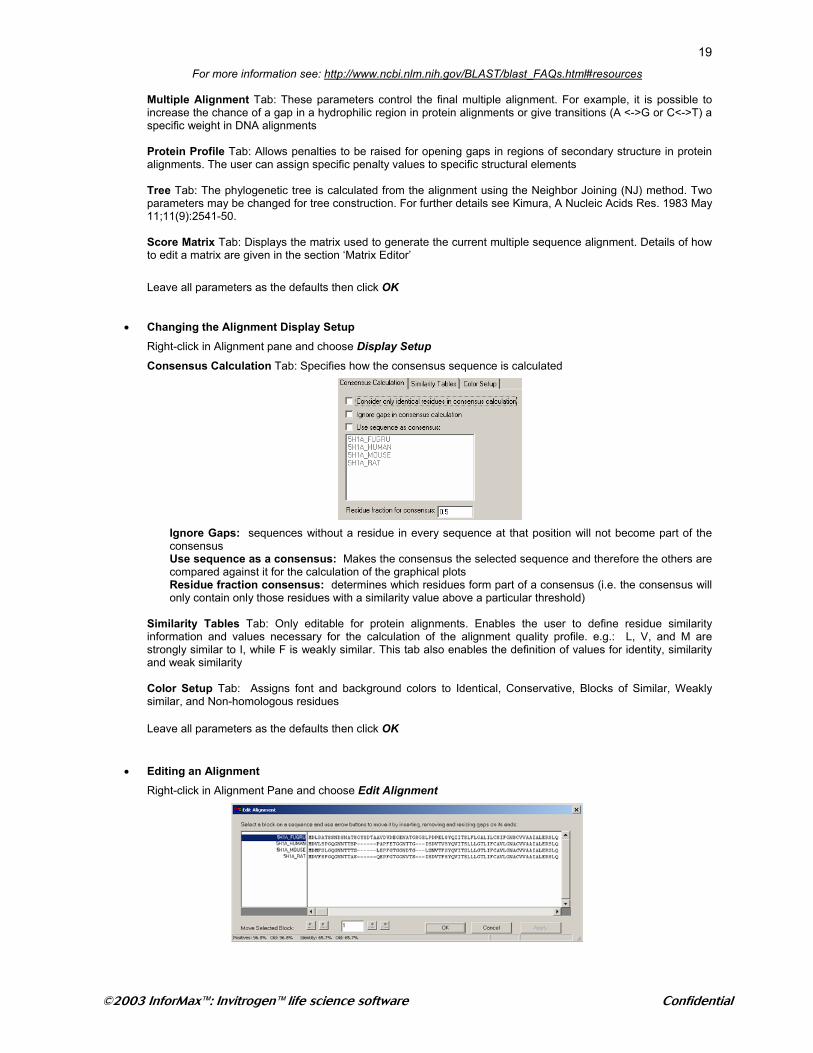
• Changing the Alignment Parameters Choose Align | Alignment Setup Pairwise Alignment Tab: These parameters control the speed and sensitivity of the initial alignments. Sequence alignment algorithms will maximize a score
FAST Algorithm: approximate method - speeds up the calculation …but at the cost of sensitivity Slow Method: uses penalties for both opening and extending gaps and a full amino acid weight matrix. These penalties should be changed to reflect the treatment of gaps e.g.: introns & exons aligned against a cDNA require minimal gap extension penalties Gap Opening & Extension Penalty: In the case of aligning DNA molecules, a match (A=A) receives a score of 1, whilst a mismatch scores zero. For proteins, the scores depend on the Score Matrix used (see below). Sequence alignment algorithms will generate an alignment with maximal score. Using the default parameters, a several mismatches are more favorable than a gap. Thus, for cDNA-genomic DNA alignments, the parameters should be changed to accommodate for introns and exons.
©2003 InforMax™: Invitrogen™ life science software Confidential
19For more information see: http://www.ncbi.nlm.nih.gov/BLAST/blast_FAQs.html#resources
Multiple Alignment Tab: These parameters control the final multiple alignment. For example, it is possible to increase the chance of a gap in a hydrophilic region in protein alignments or give transitions (A <->G or C<->T) a specific weight in DNA alignments Protein Profile Tab: Allows penalties to be raised for opening gaps in regions of secondary structure in protein alignments. The user can assign specific penalty values to specific structural elements Tree Tab: The phylogenetic tree is calculated from the alignment using the Neighbor Joining (NJ) method. Two parameters may be changed for tree construction. For further details see Kimura, A Nucleic Acids Res. 1983 May 11;11(9):2541-50.
Score Matrix Tab: Displays the matrix used to generate the current multiple sequence alignment. Details of how to edit a matrix are given in the section ‘Matrix Editor’
Leave all parameters as the defaults then click OK
• Changing the Alignment Display Setup Right-click in Alignment pane and choose Display Setup
Consensus Calculation Tab: Specifies how the consensus sequence is calculated
Ignore Gaps: sequences without a residue in every sequence at that position will not become part of the consensus Use sequence as a consensus: Makes the consensus the selected sequence and therefore the others are compared against it for the calculation of the graphical plots Residue fraction consensus: determines which residues form part of a consensus (i.e. the consensus will only contain only those residues with a similarity value above a particular threshold)
Similarity Tables Tab: Only editable for protein alignments. Enables the user to define residue similarity information and values necessary for the calculation of the alignment quality profile. e.g.: L, V, and M are strongly similar to I, while F is weakly similar. This tab also enables the definition of values for identity, similarity and weak similarity Color Setup Tab: Assigns font and background colors to Identical, Conservative, Blocks of Similar, Weakly similar, and Non-homologous residues Leave all parameters as the defaults then click OK
• Editing an Alignment Right-click in Alignment Pane and choose Edit Alignment
©2003 InforMax™: Invitrogen™ life science software Confidential
20
Highlight the desired region by ‘clicking and dragging’ through the sequence (or double-click to highlight the entire region between 2 gaps) Editing can only shift selected sequences into adjacent gaps
Use the 4 buttons at the bottom of the dialog box to shift the selected block of sequence then click OK
Note: If further editing capabilities are needed, export the alignment as an *.msf file (choose Project | Export MSF Format) which can be imported into other editing programs
• Realigning a Selected Area of the Alignment Click and drag over the region covering the first 60 amino acids the Alignment pane to highlight it
From the menu bar choose Align | Alignment Setup
Change some of the alignment parameters then click OK
Right-click in the Alignment pane and choose Realign Selected Area Notice that the new alignment parameters have been used to realign only the selected region of the alignment
• Finding a Sequence
In the Alignment Pane, select the name 5H1A-FUGRU
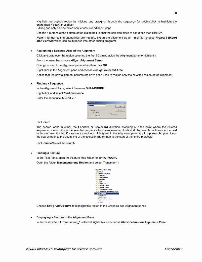
Right-click and select Find Sequence
Enter the sequence ‘MVSVLVL’
Click Find
The search looks in either the Forward or Backward direction, stopping at each point where the entered sequence is found. Once the selected sequence has been searched to its end, the search continues to the next molecule down the list. If a sequence region is highlighted in the Alignment pane, the Loop search option loops the search back to the beginning of the selection rather than to the start of the entire molecule Click Cancel to exit the search
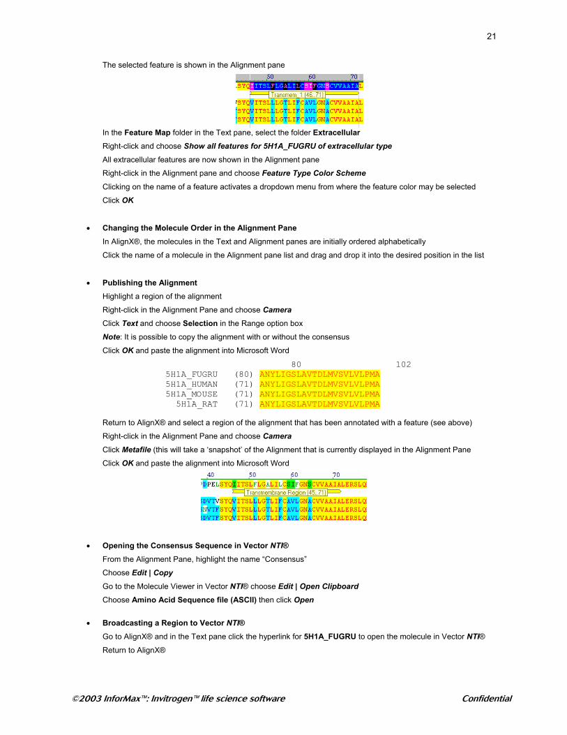
• Finding a Feature In the Text Pane, open the Feature Map folder for 5H1A_FUGRU
Open the folder Transmembrane Region and select Transmem_1
Choose Edit | Find Feature to highlight this region in the Graphics and Alignment panes
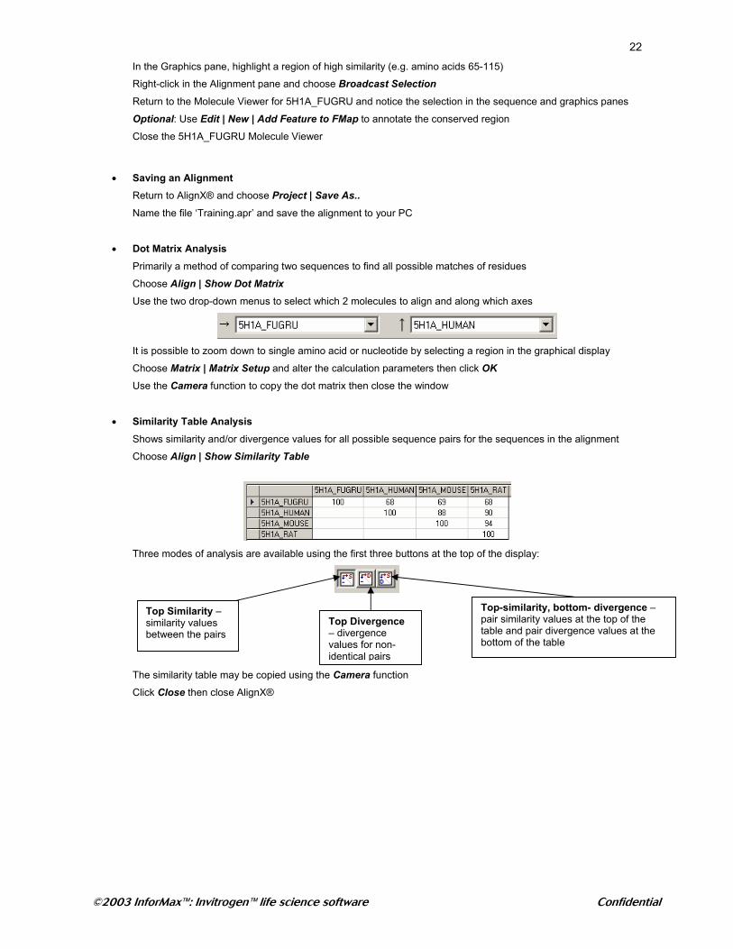
• Displaying a Feature in the Alignment Pane In the Text pane with Transmem_1 selected, right-click and choose Show Feature on Alignment Pane
©2003 InforMax™: Invitrogen™ life science software Confidential
21
The selected feature is shown in the Alignment pane
In the Feature Map folder in the Text pane, select the folder Extracellular Right-click and choose Show all features for 5H1A_FUGRU of extracellular type All extracellular features are now shown in the Alignment pane
Right-click in the Alignment pane and choose Feature Type Color Scheme
Clicking on the name of a feature activates a dropdown menu from where the feature color may be selected
Click OK
• Changing the Molecule Order in the Alignment Pane In AlignX®, the molecules in the Text and Alignment panes are initially ordered alphabetically
Click the name of a molecule in the Alignment pane list and drag and drop it into the desired position in the list • Publishing the Alignment
Highlight a region of the alignment
Right-click in the Alignment Pane and choose Camera
Click Text and choose Selection in the Range option box
Note: It is possible to copy the alignment with or without the consensus
Click OK and paste the alignment into Microsoft Word 80 102 5H1A_FUGRU (80) ANYLIGSLAVTDLMVSVLVLPMA 5H1A_HUMAN (71) ANYLIGSLAVTDLMVSVLVLPMA 5H1A_MOUSE (71) ANYLIGSLAVTDLMVSVLVLPMA 5H1A_RAT (71) ANYLIGSLAVTDLMVSVLVLPMA
Return to AlignX® and select a region of the alignment that has been annotated with a feature (see above)
Right-click in the Alignment Pane and choose Camera
Click Metafile (this will take a ‘snapshot’ of the Alignment that is currently displayed in the Alignment Pane
Click OK and paste the alignment into Microsoft Word
• Opening the Consensus Sequence in Vector NTI® From the Alignment Pane, highlight the name “Consensus”
Choose Edit | Copy Go to the Molecule Viewer in Vector NTI® choose Edit | Open Clipboard
Choose Amino Acid Sequence file (ASCII) then click Open
• Broadcasting a Region to Vector NTI®
Go to AlignX® and in the Text pane click the hyperlink for 5H1A_FUGRU to open the molecule in Vector NTI®
Return to AlignX®
©2003 InforMax™: Invitrogen™ life science software Confidential
22In the Graphics pane, highlight a region of high similarity (e.g. amino acids 65-115)
Right-click in the Alignment pane and choose Broadcast Selection
Return to the Molecule Viewer for 5H1A_FUGRU and notice the selection in the sequence and graphics panes
Optional: Use Edit | New | Add Feature to FMap to annotate the conserved region
Close the 5H1A_FUGRU Molecule Viewer
• Saving an Alignment Return to AlignX® and choose Project | Save As.. Name the file ‘Training.apr’ and save the alignment to your PC
• Dot Matrix Analysis Primarily a method of comparing two sequences to find all possible matches of residues
Choose Align | Show Dot Matrix
Use the two drop-down menus to select which 2 molecules to align and along which axes
It is possible to zoom down to single amino acid or nucleotide by selecting a region in the graphical display
Choose Matrix | Matrix Setup and alter the calculation parameters then click OK
Use the Camera function to copy the dot matrix then close the window
• Similarity Table Analysis Shows similarity and/or divergence values for all possible sequence pairs for the sequences in the alignment
Choose Align | Show Similarity Table
Three modes of analysis are available using the first three buttons at the top of the display:
The similarity table may be copied using the Camera function
Click Close then close AlignX®
Top Divergence – divergence values for non-identical pairs
Top-similarity, bottom- divergence – pair similarity values at the top of the table and pair divergence values at the bottom of the table
Top Similarity – similarity values between the pairs
©2003 InforMax™: Invitrogen™ life science software Confidential
23
ContigExpress® Pages 411-466 of the Vector NTI Advance™ 9.0 Users Manual
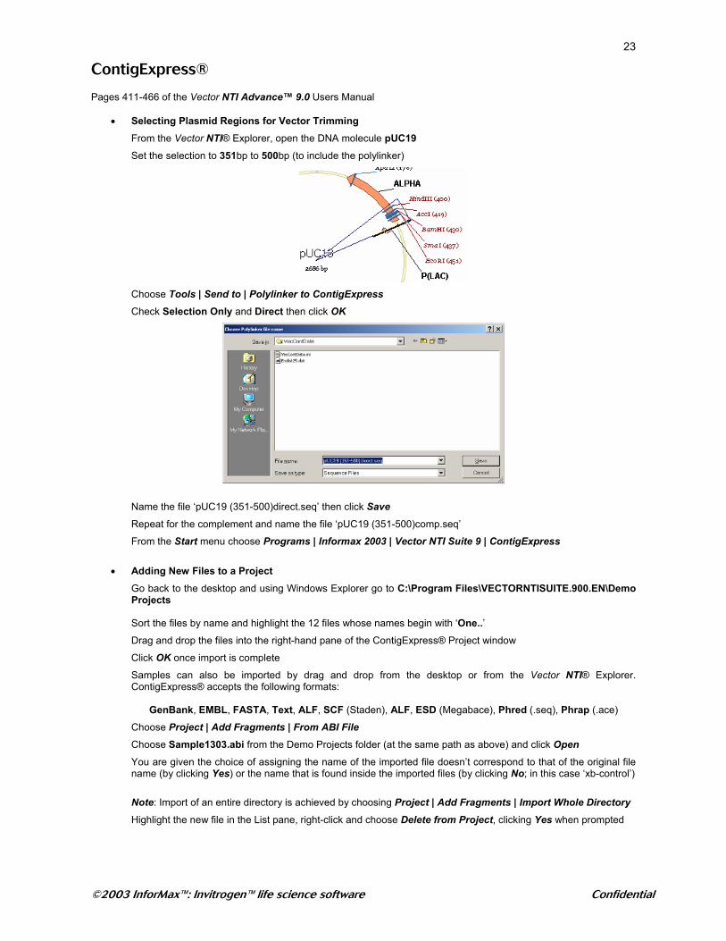
• Selecting Plasmid Regions for Vector Trimming From the Vector NTI® Explorer, open the DNA molecule pUC19 Set the selection to 351bp to 500bp (to include the polylinker)
Choose Tools | Send to | Polylinker to ContigExpress
Check Selection Only and Direct then click OK
Name the file ‘pUC19 (351-500)direct.seq’ then click Save Repeat for the complement and name the file ‘pUC19 (351-500)comp.seq’
From the Start menu choose Programs | Informax 2003 | Vector NTI Suite 9 | ContigExpress
• Adding New Files to a Project
Go back to the desktop and using Windows Explorer go to C:\Program Files\VECTORNTISUITE.900.EN\Demo Projects Sort the files by name and highlight the 12 files whose names begin with ‘One..’ Drag and drop the files into the right-hand pane of the ContigExpress® Project window
Click OK once import is complete
Samples can also be imported by drag and drop from the desktop or from the Vector NTI® Explorer. ContigExpress® accepts the following formats:
GenBank, EMBL, FASTA, Text, ALF, SCF (Staden), ALF, ESD (Megabace), Phred (.seq), Phrap (.ace)
Choose Project | Add Fragments | From ABI File
Choose Sample1303.abi from the Demo Projects folder (at the same path as above) and click Open
You are given the choice of assigning the name of the imported file doesn’t correspond to that of the original file name (by clicking Yes) or the name that is found inside the imported files (by clicking No; in this case ‘xb-control’)
Note: Import of an entire directory is achieved by choosing Project | Add Fragments | Import Whole Directory
Highlight the new file in the List pane, right-click and choose Delete from Project, clicking Yes when prompted
©2003 InforMax™: Invitrogen™ life science software Confidential
24
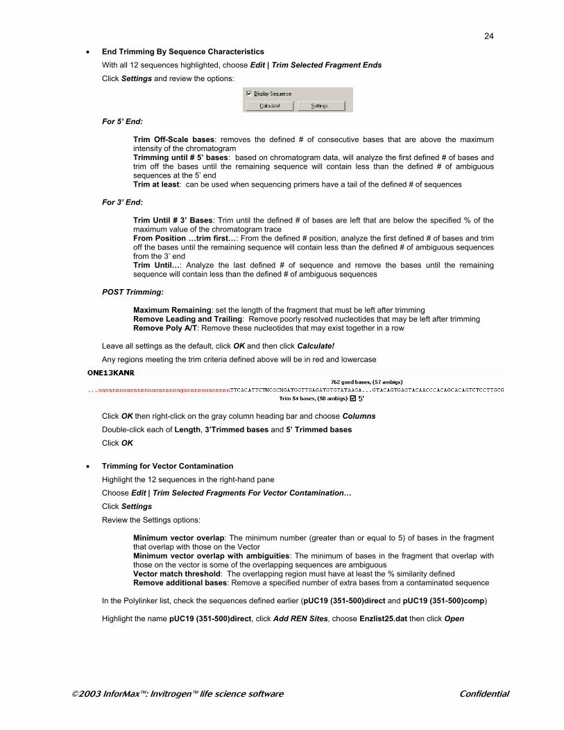
• End Trimming By Sequence Characteristics With all 12 sequences highlighted, choose Edit | Trim Selected Fragment Ends Click Settings and review the options:
For 5’ End:
Trim Off-Scale bases: removes the defined # of consecutive bases that are above the maximum intensity of the chromatogram Trimming until # 5’ bases: based on chromatogram data, will analyze the first defined # of bases and trim off the bases until the remaining sequence will contain less than the defined # of ambiguous sequences at the 5’ end Trim at least: can be used when sequencing primers have a tail of the defined # of sequences
For 3’ End:
Trim Until # 3’ Bases: Trim until the defined # of bases are left that are below the specified % of the maximum value of the chromatogram trace From Position …trim first…: From the defined # position, analyze the first defined # of bases and trim off the bases until the remaining sequence will contain less than the defined # of ambiguous sequences from the 3’ end Trim Until…: Analyze the last defined # of sequence and remove the bases until the remaining sequence will contain less than the defined # of ambiguous sequences
POST Trimming:
Maximum Remaining: set the length of the fragment that must be left after trimming Remove Leading and Trailing: Remove poorly resolved nucleotides that may be left after trimming Remove Poly A/T: Remove these nucleotides that may exist together in a row
Leave all settings as the default, click OK and then click Calculate! Any regions meeting the trim criteria defined above will be in red and lowercase
Click OK then right-click on the gray column heading bar and choose Columns
Double-click each of Length, 3’Trimmed bases and 5’ Trimmed bases
Click OK
• Trimming for Vector Contamination Highlight the 12 sequences in the right-hand pane
Choose Edit | Trim Selected Fragments For Vector Contamination… Click Settings Review the Settings options:
Minimum vector overlap: The minimum number (greater than or equal to 5) of bases in the fragment that overlap with those on the Vector Minimum vector overlap with ambiguities: The minimum of bases in the fragment that overlap with those on the vector is some of the overlapping sequences are ambiguous Vector match threshold: The overlapping region must have at least the % similarity defined Remove additional bases: Remove a specified number of extra bases from a contaminated sequence
In the Polylinker list, check the sequences defined earlier (pUC19 (351-500)direct and pUC19 (351-500)comp) Highlight the name pUC19 (351-500)direct, click Add REN Sites, choose Enzlist25.dat then click Open
©2003 InforMax™: Invitrogen™ life science software Confidential
25Click HindIII (it will change color from gray to blue)
Repeat for pUC19 (351-500)comp
Click OK then click Calculate! Any contaminated regions will be in red and lowercase
Click OK
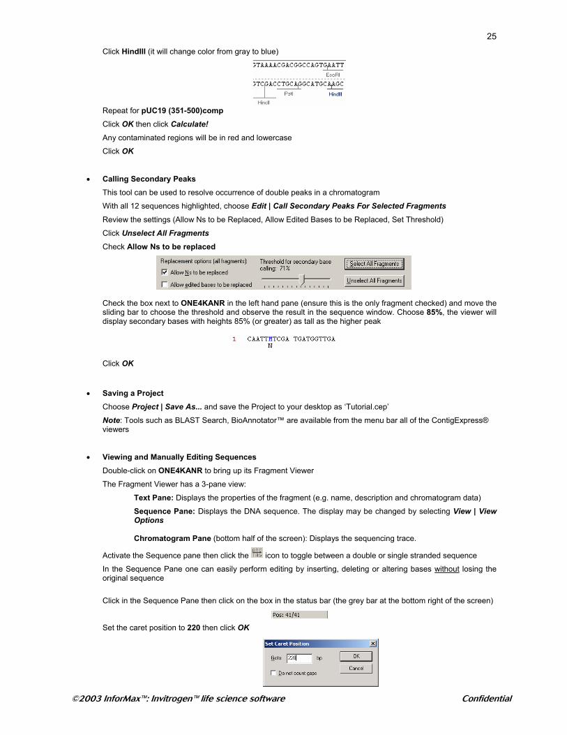
• Calling Secondary Peaks This tool can be used to resolve occurrence of double peaks in a chromatogram
With all 12 sequences highlighted, choose Edit | Call Secondary Peaks For Selected Fragments
Review the settings (Allow Ns to be Replaced, Allow Edited Bases to be Replaced, Set Threshold)
Click Unselect All Fragments
Check Allow Ns to be replaced
Check the box next to ONE4KANR in the left hand pane (ensure this is the only fragment checked) and move the sliding bar to choose the threshold and observe the result in the sequence window. Choose 85%, the viewer will display secondary bases with heights 85% (or greater) as tall as the higher peak
Click OK
• Saving a Project Choose Project | Save As... and save the Project to your desktop as ‘Tutorial.cep’ Note: Tools such as BLAST Search, BioAnnotator™ are available from the menu bar all of the ContigExpress® viewers
• Viewing and Manually Editing Sequences Double-click on ONE4KANR to bring up its Fragment Viewer
The Fragment Viewer has a 3-pane view:
Text Pane: Displays the properties of the fragment (e.g. name, description and chromatogram data)
Sequence Pane: Displays the DNA sequence. The display may be changed by selecting View | View Options Chromatogram Pane (bottom half of the screen): Displays the sequencing trace.
Activate the Sequence pane then click the icon to toggle between a double or single stranded sequence
In the Sequence Pane one can easily perform editing by inserting, deleting or altering bases without losing the original sequence
Click in the Sequence Pane then click on the box in the status bar (the grey bar at the bottom right of the screen)
Set the caret position to 220 then click OK
©2003 InforMax™: Invitrogen™ life science software Confidential
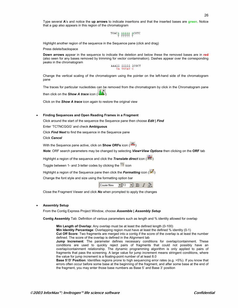
26Type several A’s and notice the up arrows to indicate insertions and that the inserted bases are green. Notice that a gap also appears in this region of the chromatogram
Highlight another region of the sequence in the Sequence pane (click and drag)
Press delete/backspace
Down arrows appear in the sequence to indicate the deletion and below these the removed bases are in red (also seen for any bases removed by trimming for vector contamination). Dashes appear over the corresponding peaks in the chromatogram
Change the vertical scaling of the chromatogram using the pointer on the left-hand side of the chromatogram pane The traces for particular nucleotides can be removed from the chromatogram by click in the Chromatogram pane
then click on the Show A trace icon ( ) Click on the Show A trace icon again to restore the original view
• Finding Sequences and Open Reading Frames in a Fragment Click around the start of the sequence the Sequence pane then choose Edit | Find
Enter ‘TCTNCGGG’ and check Ambiguous
Click Find Next to find the sequence in the Sequence pane
Click Cancel
With the Sequence pane active, click on Show ORFs icon ( )
Note: ORF search parameters may be changed by selecting View>View Options then clicking on the ORF tab
Highlight a region of the sequence and click the Translate direct icon ( )
Toggle between 1- and 3-letter codes by clicking the icon
Highlight a region of the Sequence pane then click the Formatting icon ( )
Change the font style and size using the formatting option bar
Close the Fragment Viewer and click No when prompted to apply the changes
• Assembly Setup
From the Contig Express Project Window, choose Assemble | Assembly Setup Contig Assembly Tab: Definition of various parameters such as length and % identity allowed for overlap Min Length of Overlap: Any overlap must be at least the defined length (0-100) Min Identity Percentage: Overlapping region must have at least the defined % identity (0-1)
Cut Off Score: Two fragments are merged into a contig if the score of the overlap is at least the number defined. The score of the overlap is defined in the Alignment tab Jump Increment: The parameter defines necessary conditions for overlap/containment. These conditions are used to quickly reject pairs of fragments that could not possibly have an overlap/containment relationship. The dynamic programming algorithm is only applied to pairs of fragments that pass the screening. A large value for jump increment means stringent conditions, where the value for jump increment is a floating-point number of at least 8.0 Base 5’/3’ Position: Identifies regions prone to high sequencing error rates (e.g. >5%). If you know that errors often occur before some base at the beginning of the fragment, and after some base at the end of the fragment, you may enter those base numbers as Base 5’ and Base 3’ position
©2003 InforMax™: Invitrogen™ life science software Confidential
27Alignment Tab: Define parameters for the alignments generated between fragments in contig creation (e.g. the score assigned to matching nucleotides or a mismatch). These are greyed out when using Linear Assembly Score of a match: Score given for matching bases (0-5) Score of ambiguous match: Score given for a match that includes an ambiguous residue (0-4)
Score of a mismatch: Score given to mismatched nucleotides in regions of low sequencing error rates Light Score of a mismatch: Score given to mismatches in fragment ends (region is defined by Base 3’ and Base 5’) Gap Open Penalty: Penalty score given for the first residue in a gap (0-5) Gap Extension Penalty: The penalty score given for the addition of residues in a gap in a region of low sequencing error rates (0-5) Light Gap Extension Penalty: The penalty score given for the addition of residues in a gap in the fragment ends (region defined by Base 5’ and Base 3’)
The parameters in both the above tabs can be lenient or stringent depending upon sequence quality
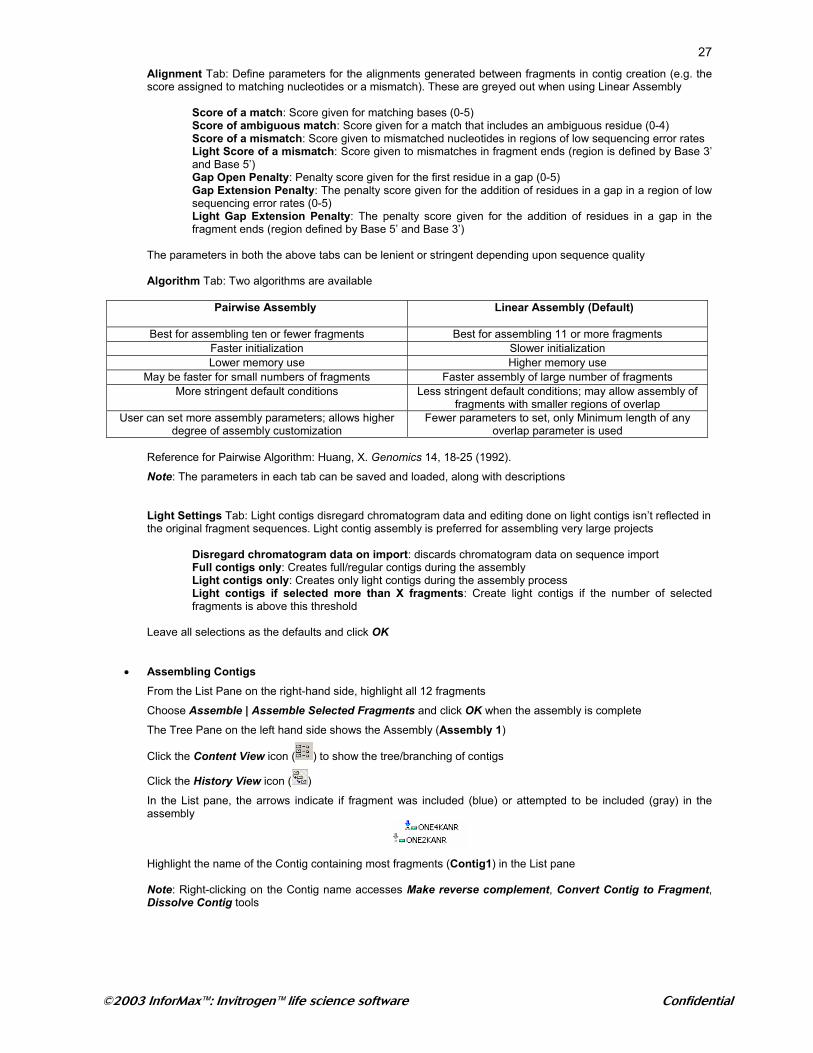
Algorithm Tab: Two algorithms are available
Pairwise Assembly Linear Assembly (Default)
Best for assembling ten or fewer fragments Best for assembling 11 or more fragments Faster initialization Slower initialization Lower memory use Higher memory use
May be faster for small numbers of fragments Faster assembly of large number of fragments More stringent default conditions Less stringent default conditions; may allow assembly of
fragments with smaller regions of overlap User can set more assembly parameters; allows higher
degree of assembly customization Fewer parameters to set, only Minimum length of any
overlap parameter is used
Reference for Pairwise Algorithm: Huang, X. Genomics 14, 18-25 (1992).
Note: The parameters in each tab can be saved and loaded, along with descriptions
Light Settings Tab: Light contigs disregard chromatogram data and editing done on light contigs isn’t reflected in the original fragment sequences. Light contig assembly is preferred for assembling very large projects
Disregard chromatogram data on import: discards chromatogram data on sequence import Full contigs only: Creates full/regular contigs during the assembly
Light contigs only: Creates only light contigs during the assembly process Light contigs if selected more than X fragments: Create light contigs if the number of selected fragments is above this threshold
Leave all selections as the defaults and click OK
• Assembling Contigs From the List Pane on the right-hand side, highlight all 12 fragments
Choose Assemble | Assemble Selected Fragments and click OK when the assembly is complete
The Tree Pane on the left hand side shows the Assembly (Assembly 1)
Click the Content View icon ( ) to show the tree/branching of contigs
Click the History View icon ( ) In the List pane, the arrows indicate if fragment was included (blue) or attempted to be included (gray) in the assembly
Highlight the name of the Contig containing most fragments (Contig1) in the List pane
Note: Right-clicking on the Contig name accesses Make reverse complement, Convert Contig to Fragment, Dissolve Contig tools
©2003 InforMax™: Invitrogen™ life science software Confidential
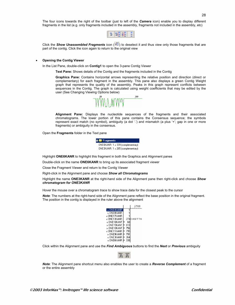
28The four icons towards the right of the toolbar (just to left of the Camera icon) enable you to display different fragments in the list (e.g. only fragments included in the assembly, fragments not included in the assembly, etc)
Click the Show Unassembled Fragments icon ( ) to deselect it and thus view only those fragments that are part of the contig. Click the icon again to return to the original view
• Opening the Contig Viewer
In the List Pane, double-click on Contig1 to open the 3-pane Contig Viewer
Text Pane: Shows details of the Contig and the fragments included in the Contig
Graphics Pane: Contains horizontal arrows representing the relative position and direction (direct or complementary) for each fragment in the assembly. This pane also displays a green Contig Weight graph that represents the quality of the assembly. Peaks in this graph represent conflicts between sequences in the Contig. The graph is calculated using weight coefficients that may be edited by the user (See Changing Viewing Options below)
Alignment Pane: Displays the nucleotide sequences of the fragments and their associated chromatograms. The lower portion of this pane contains the Consensus sequence; the symbols represent exact match (no symbol), ambiguity (a dot ‘.’) and mismatch (a plus ‘+’; gap in one or more fragments) or ambiguity in the consensus.
Open the Fragments folder in the Text pane
Highlight ONE6KANR to highlight this fragment in both the Graphics and Alignment panes
Double-click on the name ONE6KANR to bring up its associated fragment viewer
Close the Fragment Viewer and return to the Contig Viewer
Right-click in the Alignment pane and choose Show all Chromatograms
Highlight the name ONE3KANR at the right-hand side of the Alignment pane then right-click and choose Show chromatogram for ONE3KANR Hover the mouse over a chromatogram trace to show trace data for the closest peak to the cursor
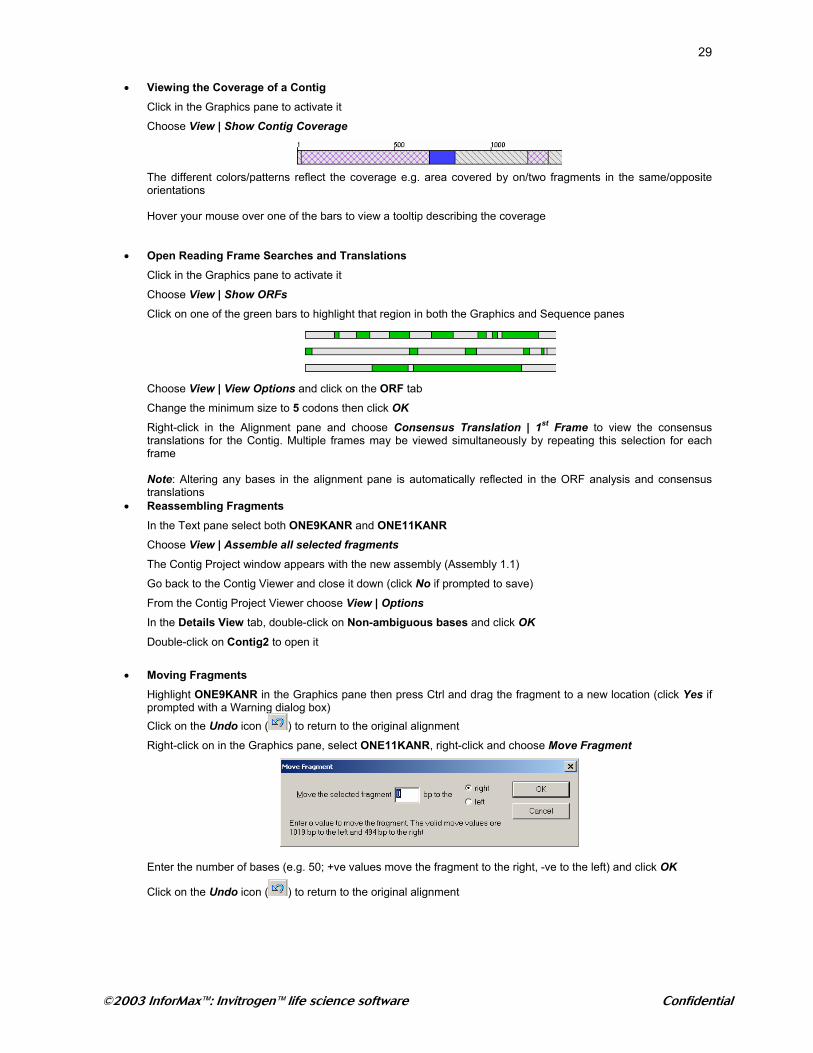
Note: The numbers at the right-hand side of the Alignment pane reflect the base position in the original fragment. The position in the contig is displayed in the ruler above the alignment
Click within the Alignment pane and use the Find Ambiguous buttons to find the Next or Previous ambiguity
Note: The Alignment pane shortcut menu also enables the user to create a Reverse Complement of a fragment or the entire assembly
©2003 InforMax™: Invitrogen™ life science software Confidential
29
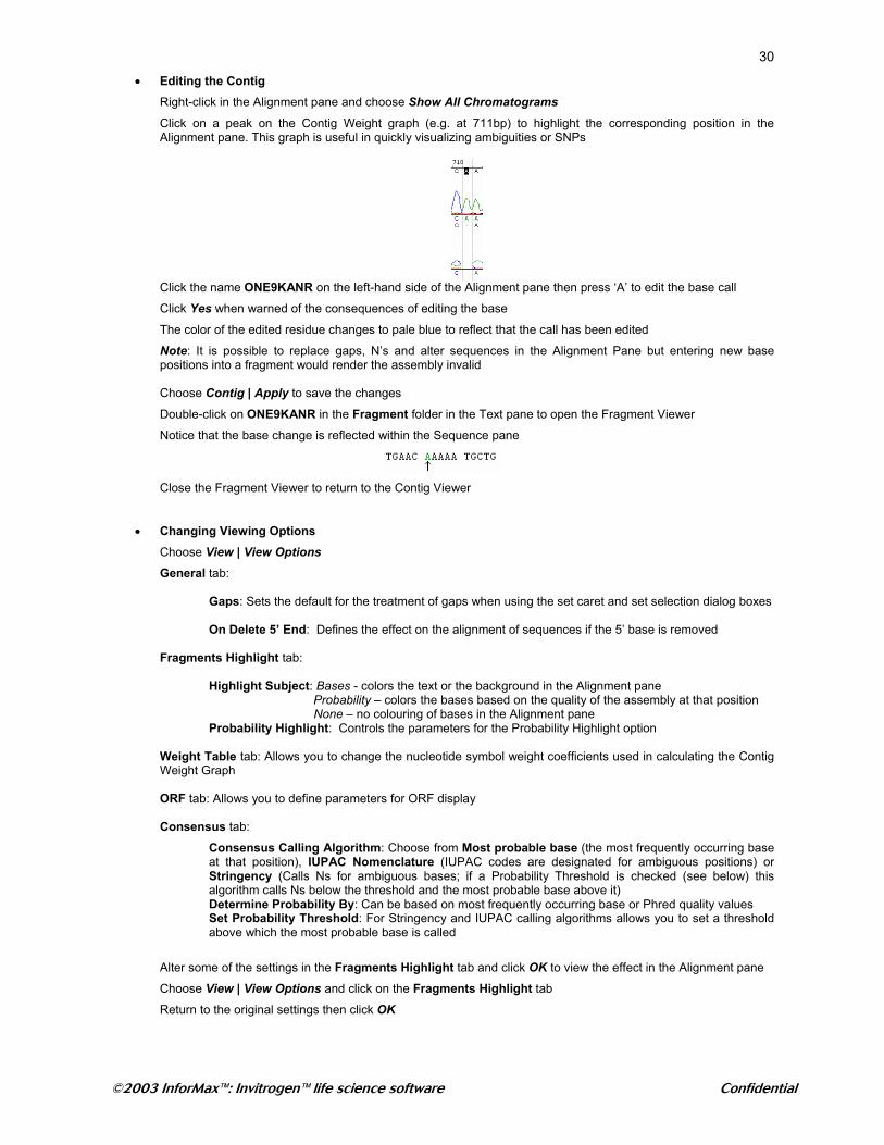
• Viewing the Coverage of a Contig Click in the Graphics pane to activate it
Choose View | Show Contig Coverage
The different colors/patterns reflect the coverage e.g. area covered by on/two fragments in the same/opposite orientations Hover your mouse over one of the bars to view a tooltip describing the coverage
• Open Reading Frame Searches and Translations Click in the Graphics pane to activate it
Choose View | Show ORFs Click on one of the green bars to highlight that region in both the Graphics and Sequence panes
Choose View | View Options and click on the ORF tab
Change the minimum size to 5 codons then click OK
Right-click in the Alignment pane and choose Consensus Translation | 1st Frame to view the consensus translations for the Contig. Multiple frames may be viewed simultaneously by repeating this selection for each frame Note: Altering any bases in the alignment pane is automatically reflected in the ORF analysis and consensus translations
• Reassembling Fragments In the Text pane select both ONE9KANR and ONE11KANR
Choose View | Assemble all selected fragments
The Contig Project window appears with the new assembly (Assembly 1.1)
Go back to the Contig Viewer and close it down (click No if prompted to save)
From the Contig Project Viewer choose View | Options In the Details View tab, double-click on Non-ambiguous bases and click OK
Double-click on Contig2 to open it
• Moving Fragments
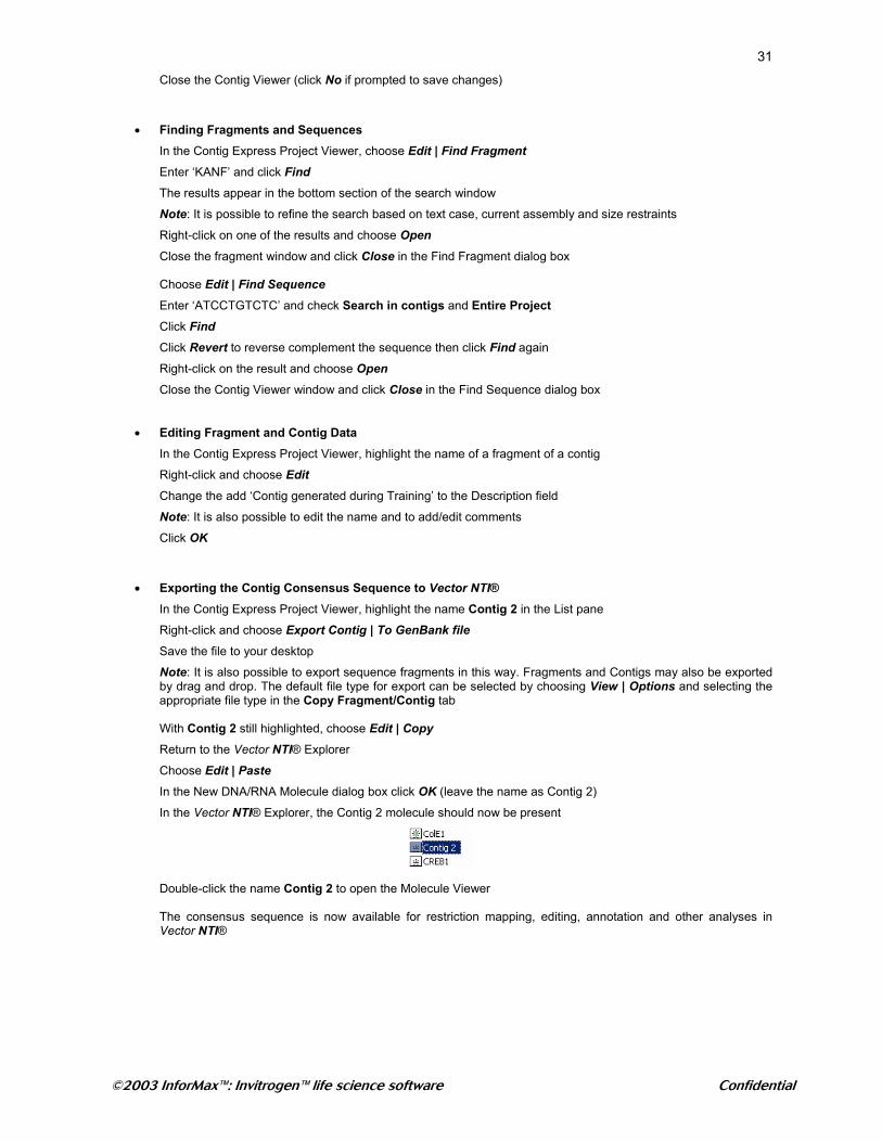
Highlight ONE9KANR in the Graphics pane then press Ctrl and drag the fragment to a new location (click Yes if prompted with a Warning dialog box) Click on the Undo icon ( ) to return to the original alignment
Right-click on in the Graphics pane, select ONE11KANR, right-click and choose Move Fragment
Enter the number of bases (e.g. 50; +ve values move the fragment to the right, -ve to the left) and click OK
Click on the Undo icon ( ) to return to the original alignment
©2003 InforMax™: Invitrogen™ life science software Confidential
30
• Editing the Contig Right-click in the Alignment pane and choose Show All Chromatograms
Click on a peak on the Contig Weight graph (e.g. at 711bp) to highlight the corresponding position in the Alignment pane. This graph is useful in quickly visualizing ambiguities or SNPs
Click the name ONE9KANR on the left-hand side of the Alignment pane then press ‘A’ to edit the base call
Click Yes when warned of the consequences of editing the base
The color of the edited residue changes to pale blue to reflect that the call has been edited
Note: It is possible to replace gaps, N’s and alter sequences in the Alignment Pane but entering new base positions into a fragment would render the assembly invalid Choose Contig | Apply to save the changes
Double-click on ONE9KANR in the Fragment folder in the Text pane to open the Fragment Viewer
Notice that the base change is reflected within the Sequence pane
Close the Fragment Viewer to return to the Contig Viewer
• Changing Viewing Options
Choose View | View Options
General tab: Gaps: Sets the default for the treatment of gaps when using the set caret and set selection dialog boxes
On Delete 5’ End: Defines the effect on the alignment of sequences if the 5’ base is removed
Fragments Highlight tab:
Highlight Subject: Bases - colors the text or the background in the Alignment pane
Probability – colors the bases based on the quality of the assembly at that position None – no colouring of bases in the Alignment pane
Probability Highlight: Controls the parameters for the Probability Highlight option
Weight Table tab: Allows you to change the nucleotide symbol weight coefficients used in calculating the Contig Weight Graph
ORF tab: Allows you to define parameters for ORF display
Consensus tab:
Consensus Calling Algorithm: Choose from Most probable base (the most frequently occurring base at that position), IUPAC Nomenclature (IUPAC codes are designated for ambiguous positions) or Stringency (Calls Ns for ambiguous bases; if a Probability Threshold is checked (see below) this algorithm calls Ns below the threshold and the most probable base above it) Determine Probability By: Can be based on most frequently occurring base or Phred quality values Set Probability Threshold: For Stringency and IUPAC calling algorithms allows you to set a threshold above which the most probable base is called
Alter some of the settings in the Fragments Highlight tab and click OK to view the effect in the Alignment pane
Choose View | View Options and click on the Fragments Highlight tab
Return to the original settings then click OK
©2003 InforMax™: Invitrogen™ life science software Confidential
31 Close the Contig Viewer (click No if prompted to save changes)
• Finding Fragments and Sequences In the Contig Express Project Viewer, choose Edit | Find Fragment Enter ‘KANF’ and click Find
The results appear in the bottom section of the search window
Note: It is possible to refine the search based on text case, current assembly and size restraints
Right-click on one of the results and choose Open
Close the fragment window and click Close in the Find Fragment dialog box Choose Edit | Find Sequence
Enter ‘ATCCTGTCTC’ and check Search in contigs and Entire Project Click Find
Click Revert to reverse complement the sequence then click Find again
Right-click on the result and choose Open
Close the Contig Viewer window and click Close in the Find Sequence dialog box
• Editing Fragment and Contig Data In the Contig Express Project Viewer, highlight the name of a fragment of a contig
Right-click and choose Edit Change the add ‘Contig generated during Training’ to the Description field
Note: It is also possible to edit the name and to add/edit comments
Click OK
• Exporting the Contig Consensus Sequence to Vector NTI® In the Contig Express Project Viewer, highlight the name Contig 2 in the List pane
Right-click and choose Export Contig | To GenBank file
Save the file to your desktop
Note: It is also possible to export sequence fragments in this way. Fragments and Contigs may also be exported by drag and drop. The default file type for export can be selected by choosing View | Options and selecting the appropriate file type in the Copy Fragment/Contig tab With Contig 2 still highlighted, choose Edit | Copy
Return to the Vector NTI® Explorer
Choose Edit | Paste
In the New DNA/RNA Molecule dialog box click OK (leave the name as Contig 2)
In the Vector NTI® Explorer, the Contig 2 molecule should now be present
Double-click the name Contig 2 to open the Molecule Viewer The consensus sequence is now available for restriction mapping, editing, annotation and other analyses in Vector NTI®
©2003 InforMax™: Invitrogen™ life science software Confidential
32
Batch Import of Oligos
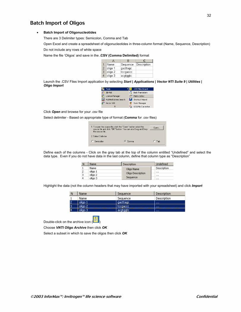
• Batch Import of Oligonucleotides There are 3 Delimiter types: Semicolon, Comma and Tab
Open Excel and create a spreadsheet of oligonucleotides in three-column format (Name, Sequence, Description)
Do not include any rows of white space
Name the file ‘Oligos’ and save in the .CSV (Comma Delimited) format
Launch the .CSV Files Import application by selecting Start | Applications | Vector NTI Suite 9 | Utilities | Oligo Import
Click Open and browse for your .csv file
Select delimiter - Based on appropriate type of format (Comma for .csv files)
Define each of the columns - Click on the gray tab at the top of the column entitled “Undefined” and select the data type. Even if you do not have data in the last column, define that column type as “Description”
Highlight the data (not the column headers that may have imported with your spreadsheet) and click Import
Double-click on the archive icon ( )
Choose VNTI Oligo Archive then click OK
Select a subset in which to save the oligos then click OK