turning corners into cameras: principles and...
TRANSCRIPT

Turning Corners into Cameras: Principles and Methods
Katherine L. Bouman1 Vickie Ye1 Adam B. Yedidia1 Fredo Durand1
Gregory W. Wornell1 Antonio Torralba1 William T. Freeman1,2
1Dept. of Electrical Engineering and Computer Science, Massachusetts Institute of Technology 2Google Research
A+BA
angularp
osition
A
A+BA
B
(c)OriginalFrame (d)ColorMagnified (e)Reconstructed1DVideoofHiddenScene
time
(b)thehiddensceneasyoumoveinacirclearoundthewall’sedge
(a)
Figure 1: We construct a 1-D video of an obscured scene using RGB video taken with a consumer camera. The stylized diagram in (a) shows a typicalscenario: two people—one wearing red and the other blue—are hidden from the camera’s view by a wall. Only the region shaded in yellow is visible to thecamera. To an observer walking around the occluding edge (along the magenta arrow), light from different parts of the hidden scene becomes visible atdifferent angles (see sequence (b)). Ultimately, this scene information is captured in the intensity and color of light reflected from the corresponding patch ofground near the corner. Although these subtle irradiance variations are invisible to the naked eye (c), they can be extracted and interpreted from a cameraposition from which the entire obscured scene is hidden from view. Image (d) visualizes these subtle variations in the highlighted corner region. We usetemporal frames of these radiance variations on the ground to construct a 1-D video of motion evolution in the hidden scene. Specifically, (e) shows thetrajectories over time that specify the angular position of hidden red and blue subjects illuminated by a diffuse light.
Abstract
We show that walls, and other obstructions with edges,can be exploited as naturally-occurring “cameras” thatreveal the hidden scenes beyond them. In particular, wedemonstrate methods for using the subtle spatio-temporalradiance variations that arise on the ground at the base ofa wall’s edge to construct a one-dimensional video of thehidden scene behind the wall. The resulting technique can beused for a variety of applications in diverse physical settings.From standard RGB video recordings, we use edge camerasto recover 1-D videos that reveal the number and trajectoriesof people moving in an occluded scene. We further showthat adjacent wall edges, such as those that arise in the caseof an open doorway, yield a stereo camera from which the2-D location of hidden, moving objects can be recovered.We demonstrate our technique in a number of indoor andoutdoor environments involving varied floor surfaces andillumination conditions.
1. IntroductionThe ability to see around obstructions would prove valu-
able in a wide range of applications. As just two examples,remotely sensing occupants in a room would be valuable insearch and rescue operations, and the ability to detect hidden,oncoming vehicles and/or pedestrians would be valuable incollision avoidance systems [2]. Although often not visibleto the naked eye, in many environments, light from obscuredportions of a scene is scattered over many of the observablesurfaces. This reflected light can be used to recover informa-tion about the hidden scene (see Fig. 1). In this work, weexploit the vertical edge at the corner of a wall to constructa “camera” that sees beyond the wall. Since vertical walledges are ubiquitous, such cameras can be found in manyenvironments.
The radiance emanating from the ground in front of acorner, e.g., at the base of a building, is influenced by manyfactors: the albedo, shape, and BRDF of its surface, aswell as the light coming from the full hemisphere above it.Assuming the ground has a significant diffuse component, amajority of the reflected light comes from the surroundings
1

that are easily seen from the observer’s position next to theoccluding wall (the visible region is shaded in yellow inFig. 1(a)). However, emitted and reflected light from behindthe corner, hidden from the observer, also has a small effecton the ground’s radiance in the form of a subtle gradient oflight encircling the corner; this is not a shadow, but is insteadwhat is referred to as a penumbra.
The faint penumbra on the ground is caused by the reflec-tion of an increasing amount of light from the hidden scene.To illustrate this, imagine standing with your shoulder upagainst the building’s wall (refer to the leftmost picture ofFig. 1(b)). At this position you are unable to see any of thescene behind the corner. However, as you slowly move awayfrom the wall, walking along the magenta circle shown inFig. 1(a), you see an increasing amount of the scene. Even-tually, the hidden scene comes fully into view. Similarly,different points on the ground reflect light integrated fromdifferently-sized fractions of the hidden scene.
Now imagine someone has entered the hidden portion ofthe scene. This person would introduce a small change tothe light coming from an angular slice of the room. Frombehind the corner this change would often not be perceptibleto the naked eye. However, it would result in a subtle changeto the penumbra; see Fig. 1(c) and (d). We use these subtlechanges, recorded from standard video cameras, to constructa 1-D version of how the hidden scene beyond the cornerevolves with time; see Fig. 1(e).
Section 2 summarizes related work that puts the presentcontribution in context. Section 3 shows how, using ourproposed methods, it is possible to identify the number andlocation of people in a hidden scene. Section 4 shows howparallax created by a pair of adjacent edges, such as in adoorway, can be used to triangulate the 2D position of mov-ing people over time. Experimental results (in the paper andsupplemental material) are shown for a number of indoorand outdoor environments with varied flooring, includingcarpet, tile, hardwood, concrete, and brick.
2. Related WorkIn this section we describe previous non-line-of-sight
(NLoS) methods. Previous methods used to see past orthrough occluders have ranged from using WiFi signals [1] toexploiting random specular surfaces [21, 4]. In this summary,we emphasize a few active and passive approaches that havepreviously been used to see past occluders and image hiddenscenes.
Recovery under Active Illumination: Past approachesto see around corners have largely involved using time-of-flight (ToF) cameras [14, 20, 10, 6]. These methods involveusing a laser to illuminate a point that is visible to boththe observable and hidden scene, and measuring how longit takes for the light to return [20, 15]. By measuring the
light’s time of flight, one can infer the distance to objectsin the hidden scene, and by measuring the light’s intensity,one can often learn about the reflectance and curvature ofthe objects [13]. Past work has used ToF methods to inferthe location [7], size and motion [12, 5], and shape [17] ofobjects in the hidden scene. These methods have also beenused to count hidden people [19].
ToF cameras work well in estimating the depths of hiddenobjects, however, they have some limitations. First, theyrequire specialized and comparatively expensive detectorswith fine temporal resolution. Second, they are limited inhow much light they can introduce in the scene to supportimaging. Third, they are vulnerable to interference fromambient outdoor illumination. By contrast, our proposed real-time passive technique operates in unpredictable indoor andoutdoor environments with inexpensive consumer cameras,without additional illumination.
In [9] a laser is used to indirectly illuminate an objectbehind an occluder. Using a standard camera the authors arethen able to identify the position of the hidden object. Similarto our proposed work, [9] uses a standard camera; however,their proposed system has a number of limitations. Namely,they require controlled conditions where the geometry of theunknown moving object is rigid, and its shape and materialare either known or can be closely modeled by a singleoriented surface element. In contrast, our method requiresminimal prior information, is completely passive, and hasbeen shown to work in many natural settings.
Passive Recovery: Other work has previously consideredthe possibility of using structures naturally present in thereal world as cameras. Naturally occurring pinholes (suchas windows) or pinspecks have been previously used fornon-line-of-sight imaging [16, 3]. In addition, specular re-flections off of human eyes have been used to image hiddenscenes [11]. Although these accidental cameras can be usedto reconstruct 2-D images, they require a more specializedaccidental camera scenario than the simple edges we proposeto use in this work.
The technique presented in [18] also detects and visu-alizes small, often imperceptible, color changes in video.However, in this work, rather than just visualize these tinycolor changes, we interpret them in order to reconstruct avideo of a hidden scene.
3. Edge CamerasAn edge camera system consists of four components:
the visible and hidden scenes, the occluding edge, and theground, which reflects light from both scenes. We refer tothe (ground) plane perpendicular to the occluding edge asthe observation plane. By analyzing subtle variations in thepenumbra at the base of an edge, we are able to deduce ahidden subject’s pattern of motion.

The reflected light from a surface at point p, with normaln, is a function of the incoming light L′i as well as thesurface’s albedo a and BRDF β. Specifically,
L′o(p, vo) = a(p)
∫L′i(p, vi)β(vi, vo, n) γ(vi, n) dvi,
(1)
where vi and vo denote the incoming and outgoing unitvectors of light at position p = (r, θ), respectively, andγ(vi, n) = vi · n. We parameterize p in polar coordinates,with the origin centered at the occluding edge and θ =0 corresponding to the angle parallel to the wall comingfrom the corner (refer to Fig. 2). For simplicity, we assumethe observation plane is Lambertian, and that the visibleand hidden scene are modeled as light emitted from a largecelestial sphere, parameterized by right ascension α anddeclination δ. Under these assumptions, we simplify (1):
L′o(r, θ) = a(r, θ)
∫ 2π
α=0
∫ π/2
δ=0
Li(α, δ) dα dδ (2)
where Li = L′iγ. Furthermore, since the occluding edgeblocks light from [π + θ, 2π] at the radial line θ,
L′o(r, θ) = a(r, θ)
[Lv +
∫ θ
φ=0
Lh(φ) dφ
](3)
for Lv =∫ πα=0
∫ π/2δ=0
Li(α, δ) dα dδ and Lh(φ) =∫ π/2δ=0
Li(π +
φ, δ) dδ. By inspecting (3) we can see that the intensityof light on the penumbra is explained by a constant term,Lv, which is the contribution due to light visible to theobserver (shaded in yellow in Fig. 1(a)), and a varying angledependent term which integrates the light in the hidden scene,Lh. For instance, a radial line at θ = 0 only integrates thelight from the scene visible to the observer, while the radialline θ = π/2 reflects the integral of light over the entirevisible and hidden scenes.
Then, if we assume that ddθa(r, θ) ≈ 01, the derivative of
the observed penumbra recovers the 1-D angular projectionof the hidden scene:
d
dθL′o(r, θ) ≈ a(r, θ)Lh(θ). (4)
But what happens if someone walks into the hidden sceneat time t, changing L0
h(θ) to Lth(θ)? In this case, the spatialderivative of the temporal difference encodes the angularchange in lighting:
d
dθ
[L′to (r, θ)− L′0o (r, θ)
]= a(r, θ)
[Lth(θ)− L0
h(θ)](5)
1In practice, we subtract a background frame to substantially removeper-pixel albedo variations. Refer to Section 3.1.1
=
yObservatio
ns:
TransferMatrix:A
x(b)SampleEstimationGainImage
DirectionofLightIntegration
Wall
1-DHiddenScene:
Positive
Negative✓ = 0
(a)ConstructingTransferMatrix
Figure 2: In (a), the transfer matrix, A, is shown for a toy situationin which observations lie along circles around the edge. In this case, Awould simply be a repeated lower triangular matrix. (b) contains an exampleestimation gain image, which describes the matrix operation performed onobservations y(t) to estimate x(t). As predicted, the image indicates thatwe are essentially performing an angular derivative in recovering a frame ofthe 1-D video.
In other words, the angular derivative of the penumbra’s dif-ference from the reference frame is a signal that indicates theangular change in the hidden scene over time. In practice, weobtain good results assuming a(r, θ) = 1 and using the cam-eras’ native encoded intensity values while subtracting thetemporal mean as a background frame (see Section 3.1.1).
3.1. Method
Using a video recording of the observation plane, wegenerate a 1-D video indicating the changes in a hiddenscene over time. These 1-D angular projections of the hiddenscene, viewed over many time-steps, reveal the trajectory ofa moving object behind the occluding edge.
Likelihood: At each time t, we relate the observed M -pixels on the projection plane, y(t), to the 1-D angular pro-jection of the hidden scene, L(t)
h (θ). We formulate a discreteapproximation to our edge camera system by describing thecontinuous image L(t)
h (θ) using N terms, x(t). The obser-vations y(t) then relate to the unknown parameters x(t) andL(t)v by a linear matrix operation:
y(t) = L(t)v + Ax(t) + w(t), w(t) ∼ N (0, λ2I),
where the M ×N matrix A is defined by the geometry ofthe system. More explicitly, each row m of A integratesthe portion of the hidden scene visible from observation m,y(t)m . In the simplified case of observations that lie on a circle
around the occluding edge, A would simply be a constantlower-triangular matrix; see Fig. 2(a).
Let A be the column augmented matrix [1 A]. We canthen express the likelihood of an observation given x(t) andL(t)v as:
p(y(t)|x(t), L(t)v ) = N
(A[L(t)v x(t)T
]T, λ21
). (6)

Prior: The signal we are trying to extract is very smallrelative to the total light intensity on the observation plane.Therefore, to improve the quality of results, we enforce spa-tial smoothness of x(t). We use a simple L2 smoothnessregularization over adjacent parameters in x(t). This corre-sponds, for a gradient matrix G, to using the prior
p(x(t)) ∝N−1∏n=1
exp
[− 1
2σ21
‖x(t)[n]− x(t)[n− 1]‖22]
N∏n=1
exp
[− 1
2σ22
‖x(t)[n]‖22]
(7)
= N (0, σ21(GTG)−1 + σ2
21). (8)
Inference: We seek a maximum a posteriori (MAP) es-timate of the hidden image coefficients, x(t), given M ob-servations, y(t), measured by the camera. By combiningthe defined Gaussian likelihood and prior distributions, weobtain a Gaussian posterior distribution of x(t) and L(t)
v ,
p(x(t), L(t)v |y(t)) = N
([L(t)v x(t)T
]T,Σ(t)
)
Σ(t) =
[λ−2AT A +
(0 0
0 GTGσ21
+ 1σ22
)]−1[L(t)v x(t)T
]T= Σ(t)λ−2ATy(t) (9)
where the maximum a posteriori estimate is given by x(t).To better understand the operation that is being performed
to obtain the 1-D reconstruction, we visualize each rowof the matrix Σ(t)λ−2AT . We refer to each reshaped rowof this matrix as the estimation gain image. An exampleestimation gain image is shown in Fig. 2b. As expected, thematrix operation is computing an angular derivative over theobservation plane. Note that although earlier we assumedddθa(r, θ) ≈ 0, in reality the albedo simply needs to beorthogonal to the zero-mean pie-wedges in each estimationgain image. We expect violations from this assumption to besmall.
3.1.1 Implementation Details
Rectification: All of our analysis thus far has assumedwe are observing the floor parallel to the occluding edge.However, in most situations, the camera will be observingthe projection plane at an angle. In order to make the con-struction of the matrix A easier, we begin by rectifying ourimages using a homography. In these results, we assume theground is perpendicular to the occluding edge, and estimatethe homography using either a calibration grid or regularpatterns, such as tiles, that naturally appear on the ground.Alternatively, a known camera calibration could be used.
Background Subtraction: Since we are interested inidentifying temporal differences in a hidden scene due to amoving subject, we must remove the effect of the scene’sbackground illumination. Although this could be accom-plished by first subtracting a background frame, L0
o, takenwithout the subject, we avoid requiring the availability ofsuch a frame. Instead, we assume the subject’s motion isroughly uniform over the video, and use the video’s meanimage in lieu of a true background frame. We found that insequences containing people moving naturally, backgroundsubtraction using the average video frame worked well.Temporal Smoothness: In addition to spatial smoothnesswe could also impose temporal smoothness on our MAP es-timate. x(t). This helps to further regularize our result, atthe cost of some temporal blurring. However, to empha-size the coherence among results, we do not impose thisadditional constraint. Each 1-D image, x(t), that we showis independently computed. Results obtained with tempo-ral smoothness constraints are shown in the supplementalmaterial.Parameter Selection: The noise parameter λ2 is set foreach video as the median variance of estimated sensor noise.The regularization parameters σ1 and σ2 are empirically setto 0.1 for all results.
3.2. Experiments and Results
Our algorithm reconstructs a 1-D video of a hidden scenefrom behind an occluding edge, allowing users to track themotions of obscured, moving objects. In all results shown,the subject was not visible to an observer at the camera.
We present results as space-time images. These imagescontain curves that indicate the angular trajectories of mov-ing people. All results, unless specified otherwise, weregenerated from standard, compressed video taken with aSLR camera. Please refer to the supplemental video for fullsequences and additional results.
3.2.1 Environments
We show several applications of our algorithm in variousindoor and outdoor environments. For each environment, weshow the reconstructions obtained when one or two peoplewere moving in the hidden scene.
Indoor: In Fig. 1(e) we show a result obtained from avideo recorded in a mostly dark room. A large diffuse lightilluminated two hidden subjects wearing red and blue cloth-ing. As the subjects walked around the room, their clothingreflected light, allowing us to reconstruct a 1-D video of col-ored trajectories. As correctly reflected in our reconstructedvideo, the subject in blue occludes the subject in red threetimes before the subject in red becomes the occluder.
Fig. 3 shows additional examples of 1-D videos recoveredfrom indoor edge cameras. In these sequences, the environ-ment was well-lit. The subjects occluded the bright ambient

HiddenScene
time
1 Person 2PeopleVideoFrameSetup
✓
Figure 3: One-dimensional reconstructed videos of indoor, hidden scenes. Results are shown as space-time images for sequences where one or two peoplewere walking behind the corner. In these reconstructions, the angular position of a person, as well as the number of people, can be clearly identified. Brightvertical line artifacts are caused by additional shadows appearing on the penumbra. We believe horizontal line artifacts result from sampling on a square grid.
Setup
Sunn
yClou
dy&
WetGroun
dClou
dy
&Rainy
time
1 Person 2PeopleVideoFrame
HiddenScene
✓
Figure 4: 1-D reconstructed videos of a common outdoor, hidden scene under various weather conditions. Results are shown as space-time images. The lastrow shows results from sequences taken while it was beginning to rain. Although artifacts appear due to the appearing raindrops, motion trajectories can beidentified in all reconstructions.
light, resulting in the reconstruction’s dark trajectory. Notethat in all the reconstructions, it is possible to count the num-ber of people in the hidden scene, and to recover importantinformation such as their angular position and speed, and thecharacteristics of their motion.
Outdoor: In Fig. 4 we show the results of a number ofvideos taken at a common outdoor location, but in differ-ent weather conditions. The top sequences were recordedduring a sunny day, while the bottom two sequences wererecorded while it was cloudy. Additionally, in the bottom se-quence, raindrops appeared on the ground during recording,while in the middle sequence the ground was fully saturatedwith water. Although the raindrops cause artifacts in thereconstructed space-time images, you can still discern thetrajectory of people hidden behind the wall.
3.2.2 Video Quality:
In all experiments shown thus far we have used standard,compressed video captured using a consumer camera. How-ever, video compression can create large, correlated noisethat may affect our signal. We have explored the effect videoquality has on results. To do this, we filmed a commonscene using 3 different cameras: an iPhone 5s, a Sony Alpha7s, and a uncompressed RGB Point Grey. Fig. 5 shows theresults of this experiment assuming different levels of i.i.d.noise. Each resulting 1-D image was reconstructed from a
single frame. The cell phone camera’s compressed videosresulted in the noisiest reconstructions, but even those resultsstill capture key features of the subject’s path.
3.2.3 Velocity Estimation
The derivative of a person’s trajectory over time, θ(t), in-dicates their angular velocity. Fig. 6 shows an example ofthe estimated angular velocity obtained from a single edgecamera when the hidden subject was walking roughly in acircle. Note that the person’s angular size and speed are bothlarger when the person is closer to the corner. Such cues canhelp approximate the subject’s 2-D position over time.
3.3. Estimated Signal Strength
In all of our presented reconstructions we show imageswith an intensity range of 0.1. As these results were obtainedfrom 8-bit videos, our target signal is less than 0.1% of thevideo’s original pixel intensities.
To better understand the signal measurement require-ments, we have developed a simple model of the edge cam-era system that both explains experimental performance andenables the study of asymptotic limits.
We consider three sources of emitted or reflected light: acylinder (proxying for a person), a hemisphere of ambientlight (the surrounding scene), and an infinitely tall half-plane(the occluding wall). If all surfaces are Lambertian, the

iPho
neSony
α7s
Point
Grey
(c)Walkingfrom2to16feetata45° Angle (d)WalkingRandomly
Sonyα7sPointGrey
iPhone
time2ft 16ft
(a)Setup (b)Noise
� = 5.2
� = 2.3
� = 0.8
✓
Figure 5: The result of using different cameras on the reconstruction of the same sequence in an indoor setting. Three different 8-bit cameras (an iPhone 5s,a Sony Alpha 7s, and an uncompressed RGB Point Grey) simultaneously recorded the carpeted floor. Each camera introduced a different level of sensornoise. The estimated standard deviation of per-pixel sensor noise, λ, is shown in (b). We compare the quality of two sequences in (c) and (d). In (c), we havereconstructed a video from a sequence of a single person walking directly away from the corner from 2 to 16 feet at a 45 degree angle from the occluded wall.This experiment helps to illustrate how signal strength varies with distance from the corner. In (d), we have done a reconstruction of a single person walkingin a random pattern. In (c) the hidden person does not change in angular position. Thus, for these results, we subtract an average background frame computedfrom a different portion of the video sequence.
Radiansp
erSecon
d
Seconds
time�
0 5 10 15 20 25 30-0.2
-0.1
0
0.1
0.2
0.3
Figure 6: A subject’s reconstructed angular velocity relative to the corneras a function of time. In this sequence, a person was walking in circles farfrom the corner.
brightness change of the observation plane due the pres-ence of the cylinder around the corner can be computedanalytically for this simple system. See the supplementarydocument.
For reasonable assumed brightnesses of the cylinder,hemisphere, and half-plane (150, 300, and 100, respectively,in arbitrary linear units), the brightness change on the ob-servation plane due to the cylinder will be an extremum of-1.7 out of a background of 1070 units. This is commensu-rate with our experimental observations of ∼ 0.1% changeof brightness over the penumbra region. Our model showsnovel asymptotic behavior of the edge camera. Namely, atlarge distances from the corner, brightness changes in thepenumbra decrease faster than would otherwise be expectedfrom a 1-D camera. This is because the arrival angle of therays from a distant cylinder are close to grazing with theground, lessening their influence on the penumbra. However,within 10 meters of the corner, such effects are small.
4. Stereo Edge Cameras
Although the width of a track recovered in the method ofthe previous section can give some indication of a hiddenperson’s relative range, more accurate methods are possibleby exploiting adjacent walls. For example, when a hiddenscene is behind a doorway, the pair of vertical doorway
LeftWall RightWall
12 3
4LeftWall RightWall
2 3
time1 4
✓L ✓R
HiddenScene
Figure 7: The four edges of a doorway contain penumbras that can be usedto reconstruct a 180◦ view of a hidden scene. The top diagram indicatesthe penumbras and the corresponding region they describe. Parallax occursin the reconstructions from the left and right wall. This can be seen inthe bottom reconstruction of two people hidden behind a doorway. Num-bers/colors indicate the penumbras used for each 90◦ space-time image.
wall edges yield a pair of corner cameras. By treating theobservation plane at the base of each edge as a camera,we can obtain stereo 1-D images that we can then use totriangulate the absolute position of a subject over time.
4.1. Method
A single edge camera allows us to reconstruct a 90◦ angu-lar image of an occluded scene. We now consider a systemcomposed of four edge cameras, such as an open doorway,as illustrated in Fig. 7. Each side of the doorway containstwo adjacent edge cameras, whose reconstructions togethercreate a 180◦ view of the hidden scene.
The two sides of the doorway provide two views of thesame hidden scene, but from different positions. This causes

Bw LeftWall RightWall
Px
Pz
✓L ✓R
Figure 8: A hidden person will introduce an intensity change on the leftand right wall penumbras at angles of θ(t)
L and θ(t)R , respectively. Once
these angles have been identified, we can recover the hidden person’s two-dimensional location using Eq. 11.
an offset in the projected angular position of the same person(see Fig. 8). Our aim is to use this angular parallax to trian-gulate the location of a hidden person over time. Assume weare observing the base of a doorway, with walls of width wseparated by a distanceB. A hidden person will introduce anintensity change on the left and right wall penumbras at an-gles of θ(t)L and θ(t)R , respectively. From this correspondence,we can triangulate their 2-D location.
P (t)z =
B − η(t)
cot θ(t)L + cot θ
(t)R
(10)
P (t)x = P (t)
z cot θ(t)L (11)
η(t) =
w cot(θR) Px ≤ 0
0 0 ≤ Px ≤ Bw cot(θL) Px ≥ B
(12)
where (Px, Pz) are the x- and z-coordinate of the person.We define the top corner of the left doorway, corner 1 inFig. 7, as (Px, Pz) = (0, 0).
Assuming the wall is sufficiently thin compared to thedepth of moving objects in the hidden scene, the η(t) termcan be ignored. In this case, the relative position of theperson can be reconstructed without any knowledge of theabsolute geometry of the doorway (e.g. B or w). In allresults shown in this paper, we have made this assumption.
Identifying Trajectories: While automatic contour trac-ing methods exist [8], for simplicity, in our stereo results,we identify the trajectories of objects in the hidden scenemanually by tracing a path on the reconstructed space-timeimages.
4.2. Experiments and Results
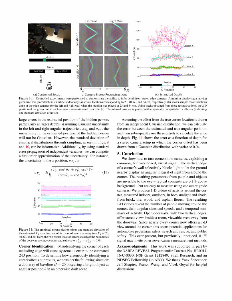
We demonstrate the ability of our method to localizethe two-dimensional position of a hidden object using fouredge cameras, such as in a doorway. We present a seriesof experiments in both controlled and uncontrolled settings.Full sequences, indicating the ground truth motions, andadditional results can be found in the supplemental material.Controlled Environment: To demonstrate the ability toinfer depth from stereo edge cameras we constructed a con-trolled experiment. A monitor displaying a slowly moving
time
LeftWall RightWall InferredPositonOverTime
time
Stereo
EdgeCameraA
Stereo
EdgeCameraB
HiddenSceneASetup HiddenSceneB
↓Baseline
Z-Position
↓Baseline
X-Position
Z-Position
X-Position
Z-Position
✓L ✓R
Figure 9: The results of our stereo experiments in a natural setting. Eachsequence consists of a single person walking in a roughly circular patternbehind a doorway. The 2-D inferred locations over time are shown as a linefrom blue to red. Error bars indicating one standard deviation of error havebeen drawn around a subset of the points. Our inferred depths capture thehidden subject’s cyclic motion, but are currently subject to large error. Asubset of B’s inferred 2-D locations have been cut out of this figure, but canbe seen in full in the supplemental material.
green line was placed behind two walls, separated by a base-line of 20 cm, at a distance of roughly 23, 40, 60, and 84cm. Fig. 10(b) shows sample space-time reconstructions ofeach 180◦ edge camera. The depth of the green line wasthen estimated from manually identified trajectories obtainedfrom these space-time images. Empirically estimated errorellipses are shown in red for a subset of the depth estimates.
Natural Environment: Fig. 9 shows the results of esti-mating 2-D positions from doorways in natural environments.The hidden scene consists of a single person walking in a cir-cular pattern behind the doorway. Although our reconstruc-tions capture the cyclic nature of the subject’s movements,they are sensitive to error in the estimated trajectories. Re-fer to Section 4.3. Ellipses indicating empirically estimatederror have been drawn around a subset of the points.
4.3. Error Analysis
There are multiple sources of error that can introducebiases into location estimates. Namely, inaccuracy in local-izing the projected trajectories, and mis-calibration of thescene cause error in the estimates. We discuss the effects ofsome of these errors below. Further derivations and analysiscan be seen in our supplemental material.
Trajectory Localization: Because Pz scales inverselywith cot(θL) + cot(θR), small errors in the estimated pro-jected angles of the person in the left and right may cause
20cm
100cm
LeftWall RightWall
LeftWall RightWall
Monitor
Locatio
n1
Locatio
n4
-40 -20 0 20 40 60
X Position
0
20
40
60
80
100
120
140
Z P
ositio
n
↓Baseline
Location 4
Location 3
Location 2
Location 1
(a)ControlledSetup (b)SampleStereoReconstructions (c)EstimatedDepth✓L ✓R
Figure 10: Controlled experiments were performed to demonstrate the ability to infer depth from stereo edge cameras. A monitor displaying a movinggreen line was placed behind an artificial doorway (a) at four locations corresponding to 23, 40, 60, and 84 cm, respectively. (b) shows sample reconstructionsdone of the edge cameras for the left and right wall when the monitor was placed at 23 and 84 cm. Using tracks obtained from these reconstructions, the 2-Dposition of the green line in each sequence was estimated over time (c). The inferred position is plotted with empirically computed error ellipses (indicatingone standard deviation of noise).
large errors in the estimated position of the hidden person,particularly at larger depths. Assuming Gaussian uncertaintyin the left and right angular trajectories, σθL and σθR , theuncertainty in the estimated position of the hidden personwill not be Gaussian. However, the standard deviation ofempirical distributions through sampling, as seen in Figs. 9and 10, can be informative. Additionally, by using standarderror propagation of independent variables, we can computea first order approximation of the uncertainty. For instance,the uncertainty in the z position, σPz
, is
σPz= B
√σ2θL
csc4 θL + σ2θR
csc4 θR
(cot θL + cot θR)4(13)
-40 -20 0 20 40 60X Position
0
20
40
60
80
100
Z Po
sitio
n
#Baseline
Figure 11: The empirical means plus or minus one standard deviation ofthe estimated Pz as a function of its x-coordinate, assuming true Pz of 20,40, 60, and 80. Here, the two corner location errors at each of the boundariesof the doorway are independent and subject to σ2
∆x = σ2∆z = 0.04.
Corner Identification: Misidentifying the corner of eachoccluding edge will cause systematic error to the estimated2-D position. To determine how erroneously identifying acorner affects our results, we consider the following situation:a doorway of baseline B = 20 obscuring a bright object atangular position θ in an otherwise dark scene.
Assuming the offset from the true corner location is drawnfrom an independent Gaussian distribution, we can calculatethe error between the estimated and true angular position,and then subsequently use these offsets to calculate the errorin depth. Fig. 11 shows the error as a function of depth fora stereo camera setup in which the corner offset has beendrawn from a Gaussian distribution with variance 0.04.
5. ConclusionWe show how to turn corners into cameras, exploiting a
common, but overlooked, visual signal. The vertical edgeof a corner’s wall selectively blocks light to let the groundnearby display an angular integral of light from around thecorner. The resulting penumbras from people and objectsare invisible to the eye – typical contrasts are 0.1% abovebackground – but are easy to measure using consumer-gradecameras. We produce 1-D videos of activity around the cor-ner, measured indoors, outdoors, in both sunlight and shade,from brick, tile, wood, and asphalt floors. The resulting1-D videos reveal the number of people moving around thecorner, their angular sizes and speeds, and a temporal sum-mary of activity. Open doorways, with two vertical edges,offer stereo views inside a room, viewable even away fromthe doorway. Since nearly every corner now offers a 1-Dview around the corner, this opens potential applications forautomotive pedestrian safety, search and rescue, and publicsafety. This ever-present, but previously unnoticed, 0.1%signal may invite other novel camera measurement methods.
Acknowledgments This work was supported in part bythe DARPA REVEAL Program under Contract No. HR0011-16-C-0030, NSF Grant 1212849, Shell Research, and anNDSEG Fellowship (to ABY). We thank Yoav Schechner,Jeff Shapiro, Franco Wang, and Vivek Goyal for helpfuldiscussions.

References[1] F. Adib and D. Katabi. See through walls with wifi! ACM,
43(4):75–86, 2013. 2[2] P. Borges, A. Tews, and D. Haddon. Pedestrian detection in
industrial environments: Seeing around corners. 2012. 1[3] A. L. Cohen. Anti-pinhole imaging. Optica Acta: Interna-
tional Journal of Optics, 29(1):63–67, 1982. 2[4] R. Fergus, A. Torralba, and W. Freeman. Random lens imag-
ing. 2006. 2[5] G. Gariepy, F. Tonolini, R. Henderson, J. Leach, and D. Fac-
cio. Detection and tracking of moving objects hidden fromview. Nature Photonics, 2015. 2
[6] F. Heide, L. Xiao, W. Heidrich, and M. B. Hullin. Diffusemirrors: 3d reconstruction from diffuse indirect illuminationusing inexpensive time-of-flight sensors. In 2014 IEEE Con-ference on Computer Vision and Pattern Recognition, pages3222–3229, June 2014. 2
[7] A. Kadambi, H. Zhao, B. Shi, and R. Raskar. Occludedimaging with time-of-flight sensors, 2016. ACM Transactionson Graphics. 2
[8] M. Kass, A. Witkin, and D. Terzopoulos. Snakes: Activecontour models. International journal of computer vision,1(4):321–331, 1988. 7
[9] J. Klein, C. Peters, J. Martın, M. Laurenzis, and M. B. Hullin.Tracking objects outside the line of sight using 2d intensityimages. Scientific reports, 6, 2016. 2
[10] M. Laurenzis, A. Velten, and J. Klein. Dual-mode opticalsensing: three-dimensional imaging and seeing around a cor-ner. Optical Engineering, 2017. 2
[11] K. Nishino and S. Nayar. Corneal imaging system: Environ-ment from eyes. International Journal of Computer Vision,70(1):23–40, 2006. 2
[12] R. Pandharkar, A. Velten, A. Bardagjy, B. M. Lawson, E., andR. Raskar. Estimating motion and size of moving non-line-of-sight objects in cluttered environments, 2011. In ComputerVision and Pattern Recognition (CVPR), 2011 IEEE Confer-ence on (pp. 265-272). 2
[13] D. Shin, A. Kirmani, V. Goyal, and J. Shapiro. Computational3d and reflectivity imaging with high photon efficiency. Im-age Processing (ICIP), 2014 IEEE International Conference,2014. 2
[14] D. Shin, A. Kirmani, V. Goyal, and J. Shapiro. Photon-efficient computational 3-d and reflectivity imaging withsingle-photon detectors. IEEE Transactions on Computa-tional Imaging, 2015. 2
[15] S. Shrestha, F. Heide, W. Heidrich, and G. Wetzstein. Com-putational imaging with multi-camera time-of-flight systems.ACM Transactions on Graphics (TOG), 2016. 2
[16] A. Torralba and W. T. Freeman. Accidental pinhole andpinspeck cameras: Revealing the scene outside the picture.Computer Vision and Pattern Recognition (CVPR). IEEE.,pages 374–381, 2012. 2
[17] A. Velten, T. Willwacher, O. Gupta, A. Veeraraghavan,M. Bawendi, and R. Raskar. Recovering three-dimensionalshape around a corner using ultrafast time-of-flight imaging.Nature Communications, 3(3):745, 2012. ACM Transactionson Graphics. 2
[18] H. Wu, M. Rubinstein, E. Shih, J. Guttag, F. Durand, andW. Freeman. Eulerian video magnification for revealing subtlechanges in the world. IEEE Signal Processing Letters, 2012.2
[19] L. Xia, C. Chen, and J. Aggarwal. Human detection usingdepth information by kinect. Computer Vision and PatternRecognition Workshops (CVPRW), 2011. 2
[20] F. Xu, D. Shin, D. Venkatraman, R. Lussana, F. Villa,F. Zappa, V. Goyal, F. Wong, and J. Shapiro. Photon-efficientcomputational imaging with a single-photon camera. Compu-tational Optical Sensing and Imaging, 2016. 2
[21] Z. Zhang, P. Isola, and E. Adelson. Sparklevision: Seeing theworld through random specular microfacets. 2014. 2