turning center - interempresas
TRANSCRIPT

Turning Center
ACCUWAY MACHINERY CO., LTD.
Shen-Gang Factory:
No.26, Lane 108, Da-Jou Road, Shen-Gang Hsiang,
Taichung Hsien, Taiwan 429, R.O.C.
TEL:+886-4-2520-9588 FAX:+886-4-2520-9716
E-mail:[email protected]
www.accuway.com.tw
Tan-Tzu Factory
No.1, Lane 113, An-Ho Road, Tan-Tzu Hsiang,
Taichung Hsien, Taiwan 427, R.O.C.
201107

UT Ser ies1 UT Ser ies 2
Rigid Structure
The machine bed is made of one-piece high-grade Meehanite casting to allow heavy cutting capabilities. The wide hardened and ground box ways are coated with Turcite and hand-scraped for ultra-precise fitting to reduce vibration while offering better tool life and surface finishes. Each axis structure is directly driven by precision
ballscrew and powered by AC servo motor for smooth slide movement with virtually no backlash.
One-piece Slant
UT-200S/UT-2 0SM
Bed Structure
UT-300Y
Multi-tasking Systems
Available on both the main spindle and sub-spindles, C1 and C2 axes provide positioning resolution up to 0.015 degree to accomplish three dimensional contour ing, combined round and pr ismat ic machining by harmonized control of the spindles with the X and Z axes. Exact synchronization between the main spindle and sub spindle at any rotation speed can be programmed to perform part transfer for secondary machining to enhance production efficiency and reduces idle time.
Main and Sub Spindles Synchronizat ion
The thermally symmetrical design on the head stock diminishes distortion and provides stable accuracy on work pieces even in continuous high speed machining. The spindle is supported by a double row of tapered roller bearings in the front and rear of the spindle to resist axial cutting force, while self-alignment angular contact bearings provide tremendous radial load capability.
Y-axis with +/- 50 mm of stroke is available for performing thread milling, complex off-center milling and drilling operations on the main or sub-spindle by combining live tool turret. The Y-axis travel is achieved by the simultaneous movement of the two independent slides. This design distributes cutting force over the two slides assuring exceptional rigidity and maximum accuracy.
Spindle
Y-axis
C1-Axis
C2-Axis
Y-Axis
Z-Axis
X-Axis
UT Ser ies3 UT Ser ies 4
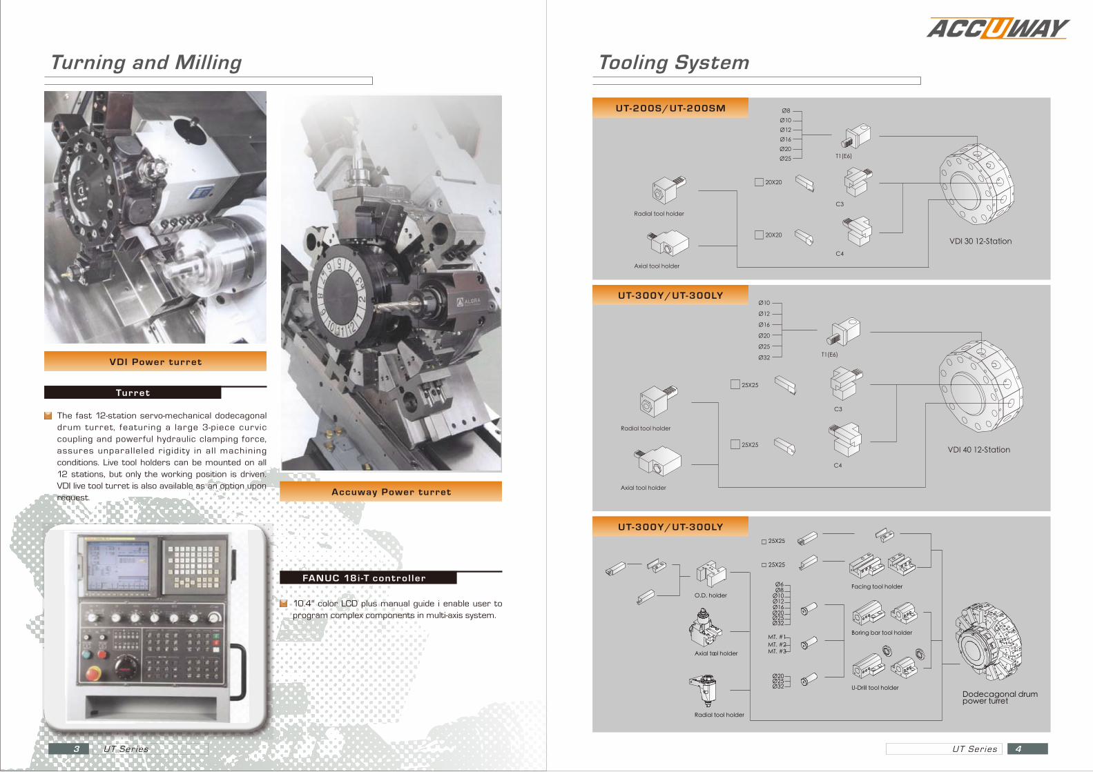
10.4" color LCD plus manual guide i enable user to program complex components in multi-axis system.
FANUC 18i -T control ler
The fast 12-station servo-mechanical dodecagonal drum turret, featuring a large 3-piece curvic coupling and powerful hydraulic clamping force, assures unparalleled r igidity in al l machining conditions. Live tool holders can be mounted on all 12 stations, but only the working position is driven. VDI live tool turret is also available as an option upon request.
Turret
VDI Power turret
Accuway Power turret
Turning and Milling
VDI 40 12-Station25X25
Ø10
Ø16Ø20
Ø12
Ø25
Axial tool holder
Radial tool holder
T1(E6)
C4
C3
Ø32
25X25
Ø16
U-Drill tool holder
Boring bar tool holder
Facing tool holder
MT. #2MT. #3
Ø32
MT. #1
Ø20Ø25
25X25
Ø8Ø10Ø12
25X25
O.D. holder
Axial tool holder
Radial tool holder
Dodecagonal drum power turret
Ø6
Ø32Ø20Ø25
Tooling System
VDI 30 12-Station20X20
Ø10
Ø16Ø20
Ø12
Ø25
Ø8
Axial tool holder
Radial tool holder
T1(E6)
C4
C3
20X20
UT-200S/UT-200SM
UT-300Y/UT-300LY
UT-300Y/UT-300LY

UT Ser ies5 UT Ser ies 6
Working Range
VDI 30 12-station power turretUT-200SM
368220 72
27040133220
Ø505
Ø266
368
Ø210
60100
600
144
23
220
150
2057
50
600
155
220
150
50 50
150144
85
307307 100
717148
57
175
60100600
220
166
170
11
303150303
220
26
7
7
150303
144
133
170
143.2 32.8
103.2126.2
13.2
Z-TRAVEL750
133 72120 10.5
115
270
240
220
250
270
75
100
X-TRAV
EL300
90175250 15
112
200
235
270
240
220
15250 83
133
270
X-TRAVEL
300
750
120
75
72
82
1
10.5
100
Z-TRAVEL
100
250
500 30080
120
35
300
500
60100
320
60115125 60110130 451101306380.5
235
241
300
170165
210
240
15
15
X-TRAV
EL
210
750
2
111.5Z-TRAVEL
110
170
4030
220
90
27 3575 35305
76
300
80
490
490
65
300
490
70
300 11
0
VDI 40 12-station power turret
Accuway power turret
UT-300SM
UT-300SM
Accuway power turretUT-300Y/UT-300LY
VDI 40 12-station power turretUT-300Y/UT-300LY
120 540/1040(UT-300L)
275
40
200
10057
85
750/1250(UT-300L)
139120 540/1040(UT-300L)
250275
40
139
750/1250(UT-300L)
85 120
901025
256
236
39
516
120275
516 275
19100
35
320
25.519
Z-TRAVEL
X-TRAV
EL
Z-TRAVEL
X-TRAV
EL
120 540/1040(UT-300L)
275
750/1250(UT-300L)
120 540/1040(UT-300L)
250275
40
139
750/1250(UT-300L)
85 120
901025
256
236
39
516
120275
516 275
19100
35
320
25.519
Z-TRAVEL
X-TRAV
EL
Z-TRAVEL
X-TRAV
EL
120 540/1040(UT-300L)
275
40
200
10057
127
85
750/1250(UT-300L)
139120 540/1040(UT-300L)
250275
40
139
750/1250(UT-300L)
85 120
901025
256
236
39
516
120275
516 275
19100
35
320
25.519
Z-TRAVEL
X-TRAV
EL
Z-TRAVEL
X-TRAV
EL
275 189
205
260
90100540/1040(UT-300L)120
540/1040(UT-300L)120
540/1040(UT-300L)120540/1040(UT-300L)120
90100
175
239
245
275
139139
750/1250(UT-300L) 750/1250(UT-300L)
105
20
55 90
165
2517162
245
260
271
275
15
40
150
9010586139
750/1250(UT-300L)
139
525
35 70
200
224
245
260
275
90100140
3
260
245
135140
750/1250(UT-300L)
66
64
79.5
Z-TRAVEL
X-TRAV
EL
Z-TRAVEL
X-TRAV
EL
Z-TRAVEL
X-TRAV
EL
Z-TRAVEL
X-TRAV
EL

Accuway power turret
UT Ser ies7 UT Ser ies 8
Working Range
VDI 40 12-station power turretUT-300SY
UT-300SY
Machine Dimensions
Spindle Torque Diagram
1735
15903895
2965
UT-200S/UT-200SM
B
CD
A
UT-300Y/UT-300LY MODEL A B C D
UT-300Y 3500 2200 2050 4050
UT-300LY 4100 2200 2050 4650
Output[kW]
0
5
10
15
20
0 30001500 4500 6000
30 min, S3 60% Operating zone15 kW
Continuous operating zone
11 kW
Torque[N-m]
60000 1500 45003000
250
191200
150140
100
50
0
30 min, S3 60%Operating zone
Continuousoperating zone
Motor speed [ min-1 ]
Output[kW]
0
6
12
18
24
0 700 1400 3500
15 min, S3 60% Operating zone18.5 kW
Continuousoperating zone
15 kW
Torque[N-m]
35000 700 1400
450432
300
150
0
15 min, S3 60%Operating zone
Continuousoperating zone
600
338338
Motor speed [ min-1 ]
Motor speed [ min-1 ] Motor speed [ min-1 ]
522
2100 2800
2029
2100 2800
700 700
[ αP 22 ]
[ αP 30 ]
275
100
516
320
19
ø242
ø472
35120516
275
39
750 75Z-axis stroke
750
10.5 90
6560
87
16
Z-axis stroke
X-ax
is str
oke
275
X-ax
is str
oke
275
250 190
72 120
46
67
560
250
236 11
0
120
153
6
275494
86
494 105
36
275
ø231
ø448
49470
27551
750
79.5
182182 122112
163.5143.5
111.561.5
10
64
Z-axis stroke
275
39
25
55 60 90 105
175
65
X-ax
is str
oke
200 11
0
750
182 62 60
5
80
7035
4
Z-axis stroke
275
200
1024
165
X-ax
is str
oke

UT Ser ies9 UT Ser ies 10
UT-200 SpecificationMachine Model UT-200S UT-200SM
Controller FANUC OiT FANUC OiT
CAPACITY
Swing over “ Z” cover mm 522 522
Swing over “ X” cover mm 318 318
Max cutting diameter (Main spindle) mm 260 286
Max cutting diameter (Sub-spindle) mm 260 286
Max cutting length mm 495 495
MAIN SPINDLE
Spindle nose ASA A 2-6 A 2-6
Spindle bearing inner diameter mm 100 110 100 110
Power chuck diameter inch 8 8
Spindle speed rpm 4500 4000 4500 4000
Spindle drive KW 11/15 11/15
Bar capacity mm 52 65 52 65
SUBSPINDLE
Spindle nose ASA A 2-5 A 2-5
Power chuck diameter inch 6 6
Spindle speed rpm 6000 6000
Spindle drive power
power
KW 5.5/7.5 5.5/7.5
Bar capacity mm 45 45
TRAVELS
Z axis mm 600 600
X axis mm 220 220
B axis mm 625 625
FEEDS
Rapid traverse- Z axis m/min 20 20
Rapid traverse- X axis m/min 20 20
Rapid traverse- B axis m/min 20 20
TOOL TURRET
Type Hydraulic Servo-mechanical
Number of tools units 12 (VDI 30) 12 (VDI 30)
Tool size square(Machining the face) mm 20 20
Tool size square(Machining the back) mm 20 20
Tool size boring bar mm 32 32
Cs spindle index angle degree - 0.015
Max. rotary tool speed rpm - 6000
Rotary tool driver power kW - 2.2
DIMENSIONS
Floor space required M 2.9 x 1.6 2.9 x 1.6
Height M 1.7 1.7
Weight kg 4000 4000
UT-300 SpecificationMachine Model UT-300Y UT-300LY UT-300SM UT-300SYController FANUC 0iT FANUC 0iT FANUC OiT FANUC 18iTCAPACITYSwing over “ Z” cover mm 910 910 612 910
Swing over “ X” cover mm 720 720 388 720
Max cutting diameter (Main spindle) mm 470 470 420 450
Max cutting diameter (Sub-spindle) mm - - 375 375
Max cutting length mm 610 1140 610 610
MAIN SPINDLE Spindle nose ASA A2-8 A2-8 A2-11 A2-8 A2-8
Spindle bearing inner diameter mm 130 140 130 140 160 130 140 130 140
Power chuck diameter inch 10 12 10 12 15 10 12 10 12
Spindle speed rpm 3500 2700 3500 2700 2500 3500 2700 3500 2700
Spindle drive power KW 15/18.515/18.5
(18.5/22) 15/18.5 15/18.5
Bar capacity mm 75 90 75 90 105 75 90 75 90
SUBSPINDLE Spindle nose ASA - - A2-5 A2-5
Power chuck diameter inch - - 6 6
Spindle speed rpm - - 6000 6000
Spindle drive power KW - - 5.5/7.5 5.5/7.5
Bar capacity mm - - 45 45
TRAVELSZ axis mm 750 1250 750 750
Y axis mm ± 50 ± 50 - ± 50
X axis mm 275 275 300 275
B axis mm - - 700 700
FEEDSRapid traverse- Z axis m/min 24 24 24 24
Rapid traverse- Y axis m/min 10 10 - 10
Rapid traverse- X axis m/min 20 20 20 20
Rapid traverse- B axis m/min - - 20 20
TOOL TURRETType APT / VDI APT / VDI APT / VDI APT / VDI
Number of tools station 12 12 12 12
Tool size square mm 25 25 25 25
Tool size boring bar mm 40 40 40 40
Cs spindle index angle deg 0.015 0.015 0.015 0.015
Max. rotary tool speed rpm 4000 4000 4000 4000
Rotary tool driver power kW 3 / 3.7 3 / 3.7 3 / 3.7 3 / 3.7
TAILSTOCKTailstock body travel mm 540 1040 - -
Quill travel mm 120 120 - -
Quill diameter mm 85 85 - -
Quill taper hole MT 5 5 - -
Tailstock body positioning Programmable Programmable - -
DIMENSIONS Floor space required M 3.5 X 2 4 X 2 3 X 1.9 3.5 X 2
Height M 2.2 2.2 2 2.2
Weight kg 6000 7500 5900 6500