turbulent drag reduction using sinusoidal riblets with triangular cross...
TRANSCRIPT

AIAA-2008-374538th AIAA Fluid Dynamics Conference and Exhibit, June 23-26 2008, Seattle, WA
Turbulent Drag Reduction using Sinusoidal Riblets
with Triangular Cross-Section
Yulia Peet∗ and Pierre Sagaut†
Universite Pierre et Marie Curie - Paris 6, 75252 Paris, France
Yves Charron‡
IFP- Institut Francais du Petrole, 92852 Rueil Malmaison, France
It is known that longitudinal ribs manufactured in a flat surface act to reduce turbulentskin-friction drag, providing a moderate drag reduction of 4 to 8%. It is shown in thispaper that this value can be increased by at least 50% if sinusoidal-like rods are usedinstead of conventional straight riblets. Large Eddy Simulation of a turbulent flow over ariblet-covered surface is performed for three cases: straight riblets and sinusoidal ribletswith two different values of wavelength. All riblets have triangular cross-section. It is foundthat drag reduction with sinusoidal riblets depend strongly on the wavelength, showing abenefit over straight riblets for a larger value of the wavelength, and an opposite trend -for a smaller value. Different nature of the flow over straight and sinusoidal riblet surfacesis revealed by looking at crossflow motion in transverse planes, mean and instantaneousstreamwise vorticity, and organized coherent structures. Turbulent statistics is comparedbetween all three cases, crossflow turbulence intensity is reduced for sinusoidal riblets asopposed to straight riblets.
I. Introduction
Riblets, or wall grooves manufactured in a surface, are attractive drag-reducing devices because of theirlow production cost and easiness of maintenance.1–8 They can be successfully installed on wings of anaircraft, hull of a submarine or internal walls of a gas pipeline by adding special plastic films with sub-millimeter scale riblets which are available commercially.7,9 An unfortunate disadvantage of riblets is ratherlow amount of drag reduction which they can offer: the best values have been achieved with infinitely-thinblade riblets giving about 10% reduction for an optimized configuration;8 while more realistic cross-sectionsfor industrial use, such as triangular, V-groove or scalloped, usually account for 4–8% drag reduction.1–8 Aneasy modification to the riblet method, retaining its structural simplicity but improving its drag reductionperformance, would be more than welcome!
One of the new methods proposed in literature devoted to turbulent skin-friction drag reduction is high-frequency spanwise wall oscillations.10–15 It is argued that oscillatory motion of the wall makes longitudinalboundary layer vortices move in a sinuous form, which reduces their strength and, consequently, their abilityto produce turbulence through near-wall burst events,16 resulting in a lower turbulent skin-friction drag. Inpractical applications, it is usually not possible to provide sustainable oscillations of the surface. However,if one can mimic such an oscillatory motion with the help of some passive devices, that should have moreor less similar effect. In was recently proposed to use riblets to guide the flow into oscillatory motion bychanging the shape of riblets from conventional straight rods into sinusoidal rods.17 By combining thesetwo drag reduction mechanisms (riblets and oscillatory flow motion), it is hoped that the benefits of the twomethods will also be combined.
∗Postdoctoral Researcher, Institut Jean le Rond d’Alembert, AIAA Member, E-mail: [email protected]†Professor, Institut Jean le Rond d’Alembert‡Research EngineerCopyright c© 2008 by the American Institute of Aeronautics and Astronautics, Inc. The U.S. Government has a royalty-free
license to exercise all rights under the copyright claimed herein for Governmental purposes. All other rights are reserved by thecopyright owner.
1 of 9
American Institute of Aeronautics and Astronautics Paper AIAA-2008-3745

This paper documents Large Eddy Simulation (LES) study of turbulent flow in a channel, one wall ofwhich is covered with riblets of triangular cross-section, and the other wall is flat. Computations of threegeometries are performed: conventional straight riblets (with the results compared to DNS data of Choi etal.6) and two cases of sinusoidal riblets with different wavelengthes of riblet oscillations. It is found that thewavelength of riblet oscillations equal to 3.22 δ results in a smaller drag reduction than the straight ribletcase. However, if the wavelength is increased to 6 δ, drag reduction achieved with the sinusoidal riblets isabout 50% larger than that with the straight riblets, demonstrating clear benefits of the former method.Strong dependence of drag reduction properties on the oscillation period was also reported for the case ofspanwise-oscillating wall,10,18 phenomenon not yet understood.
II. Numerical Method and Simulation Parameters
LES code used in the present study is unstructured second-order incompressible solver with finite-volume scheme, Code Saturne, developed at Electricite de France(EDF).19 In addition to extensive testingof Code Saturne performed in EDF,19 LES of turbulent plane channel flow at Reτ = 180 was performedwith this code as a part of the current study, and resulting turbulent mean flow and second-order quantitiesagree well with available DNS data.17
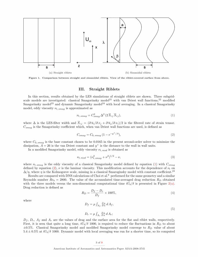
Computational geometry for riblet calculations consists of a channel whose top wall is a flat wall andbottom wall is covered with riblets. Riblets have triangular cross-section with the riblet ridge angle α = 60◦.The difference between straight riblets and sinusoidal riblets is highlighted in Figure 1. Sinusoidal ribletgeometry has two more important parameters compared to straight riblets: amplitude a and wavelength λof the oscillations. Parameters of the computational domain are summarized for the three simulated cases inTable 1 in δ units and in Table 2 in wall units. Here δ is half of the distance between the midpoint betweentip and valley on a riblet wall and a flat wall and thus corresponds to the half-width of the plane channel withthe same cross-sectional area. Lx and Lz are streamwise and spanwise computational periods (as periodicboundary conditions are used in these directions), s is the riblet spacing and h is the riblet height. For thetwo sinusoidal cases, wavelength λ and amplitude a are varied in a manner so that the maximum slope ofthe sinusoidal curve 2 π a/λ remains constant corresponding to an angle β = 11.3◦ (Figure 1(b)). Size of thecomputational domain is chosen large enough to guarantee that natural coherence of organized turbulencestructures in a boundary layer is not disturbed by insufficient domain size (L+
x > 300, L+z > 100).20 Reynolds
number based on δ and bulk velocity is 2730. This Reynolds number corresponds to Reτ = 180 basedon a friction velocity which would develop in a plane channel flow with the same bulk Reynolds number.Computations are initialized by adding synthetic turbulent fluctuations to the laminar solution. Calculationsare advanced with the time step ∆ tUb/δ ∼ 0.03, or ∆ t+ ∼ 0.3.
Case Lx/δ Lz/δ s/δ h/δ a/δ λ/δ Nx ×Ny ×Nz
Straight 3.22 0.93 0.1164 0.1 0 0 16× 64× 128Sinus 1 3.22 0.93 0.1164 0.1 0.1 3.22 16× 64× 128Sinus 2 6 0.93 0.1164 0.1 0.19 6 32× 64× 128
Table 1. Parameters of the computational domain in δ units.
Case L+x L+
z s+ h+ a+ λ+ ∆x+ ×∆y+ ×∆z+
Straight 580 165 21 18 0 0 36× (0.4− 14)× 1.28Sinus 1 580 165 21 18 18 580 36× (0.4− 14)× 1.28Sinus 2 1080 165 21 18 34 1080 33× (0.4− 14)× 1.28
Table 2. Parameters of the computational domain in wall units.
2 of 9
American Institute of Aeronautics and Astronautics Paper AIAA-2008-3745
x
z
x
zsss
U∞U∞
(a) Straight riblets
a
λ
s
β
a
λλ
ss
β
(b) Sinusoidal riblets
Figure 1. Comparison between straight and sinusoidal riblets. View of the riblet-covered surface from above.
III. Straight Riblets
In this section, results obtained by the LES simulations of straight riblets are shown. Three subgrid-scale models are investigated: classical Smagorinsky model21 with van Driest wall functions,22 modifiedSmagorinsky model23 and dynamic Smagorinsky model24 with local averaging. In a classical Smagorinskymodel, eddy viscosity νt, smag is approximated as
νt, smag = C2smag ∆2 (2 Si j Si j), (1)
where ∆ is the LES-filter width and Si j = (∂ ui/∂ xj + ∂ uj/∂ xi)/2 is the filtered rate of strain tensor.Csmag is the Smagorinsky coefficient which, when van Driest wall functions are used, is defined as
Csmag = C0, smag (1− e−y+/A), (2)
where C0, smag is the base constant chosen to be 0.0165 in the present second-order solver to minimize thedissipation, A = 26 is the van Driest constant and y+ is the distance to the wall in wall units.
In a modified Smagorinsky model, eddy viscosity νt, mod is obtained as
νt, mod = (ν2t, smag + ν2)1/2 − ν, (3)
where νt, smag is the eddy viscosity of a classical Smagorinsky model defined by equation (1) with Csmag
defined by equation (2), ν is the laminar viscosity. This modification accounts for the dependence of νt on∆/η, where η is the Kolmogorov scale, missing in a classical Smaroginsky model with constant coefficient.23
Results are compared with DNS calculations of Choi et al.6 performed for the same geometry and a similarReynolds number Reb = 2800. The value of the accumulated time-averaged drag reduction RD obtainedwith the three models versus the non-dimensional computational time tUb/δ is presented in Figure 2(a).Drag reduction is defined as
RD =Df −Dr
Df× 100%, (4)
whereDf = µ
∫Af
∂ u∂ n dAf ,
Dr = µ∫
Ar
∂ u∂ n dAr;
(5)
Df , Dr, Af and Ar are the values of drag and the surface area for the flat and riblet walls, respectively.First, it is seen that quite a long time, tUb/δ 1000, is required to reduce the fluctuations in RD to about±0.5%. Classical Smagorinsky model and modified Smagorinsky model converge to RD value of about5.4± 0.5% at tUb/δ 1000. Dynamic model with local averaging was run for a shorter time, so its computed
3 of 9
American Institute of Aeronautics and Astronautics Paper AIAA-2008-3745

RD value of 6.5%17 would most likely drop down to ∼ 5.4% as well. This value is consistent with thetypical drag reduction values for the riblets with triangular cross-section reported in other experimentaland computational studies.1–8 Drag reduction of 6% was obtained in DNS calculations of Choi et al.6
However, their averaging time was only tUb/δ ∼ 330, after which, according to their estimation, the remainingfluctuations of averaged wall-shear rates were about ±2%. It is confirmed by the Figure 2(a) that fluctuationsare still quite significant after the averaging time of tUb/δ ∼ 330, indeed about ±2%.
200 400 600 800 1000 1200
t Ub / δ
2
4
6
8
10
12
RD
, %
4.9%
5.9%
(a) Straight riblets. ——–, classical Smagorinsky model; −−−modified Smagorinsky model; − · − · −, dynamic model withlocal averaging.
200 400 600 800 1000 1200
t Ub / δ
-4
0
4
8
12
RD
, %
-0.5%
5.4%
7.4%
(b) Sinusoidal riblets. ——–, straight case; −−− Sinus 1 case,λ/δ = 3.22; − · − · −, Sinus 2 case, λ/δ = 6.
Figure 2. Value of the drag reduction versus non-dimensional computational time.
Turbulence statistics for the three models is compared in Figure 3, where mean streamwise velocityas well as root-mean square velocity fluctuations are shown. Results from DNS of Choi et al.6 are alsoplotted for comparison. Mean velocity is normalized with Ul to be consistent with the plots of Choi etal.6 (Ul is the centerline velocity which would occur in a laminar plane channel flow with the same bulkvelocity, i.e. Ul = 1.5 Ub). Velocity fluctuations are normalized with Uc, where Uc is the turbulent centerlinevelocity. It can be seen that dynamic model with local averaging significantly underpredicts normal andspanwise Reynolds stresses. Misbehavior of the dynamic model is explained by the absence of averagingalong the homogeneous directions as usually done for a plane channel.17 Both classical Smagorinsky andmodified Smagorinsky models show generally good agreement with DNS data,6 but modified Smagorinskymodel results in slightly higher values of normal and spanwise velocity fluctuations on a flat wall. Sincesuperiority of the modified Smagorinsky model over the classical model was not observed in this case, theauthors decided to choose classical Smagorinsky model for the calculations of sinusoidal riblets.
Drag reduction mechanism with the straight riblets as deduced from the current LES was highlighted inRef. 17. It was confirmed by looking at snapshots of streamwise vorticity and three-dimensional coherentstructures that quasi-streamwise vortices are displaced by the riblets away from the wall. Thus the surfacearea subjected to the downwash of high-speed fluid by the vortices is reduced leading to the subsequentdecrease in drag.6
IV. Sinusoidal Riblets
Sinusoidal spanwise variation of the riblet shape is proposed in order to introduce an oscillating spanwisecomponent into the near-wall mean flow. The hope is that such a flow will resemble the flow over spanwise-oscillating plate, for which significant drag reduction is known to occur compared to a stationary plate.10–15
As laminar analysis shows,17 resulting riblet crossflow boundary layer indeed closely resembles a Stokes layerwhich is a theoretical laminar solution for the flow over an oscillating wall.25 Spanwise velocity profiles taken
4 of 9
American Institute of Aeronautics and Astronautics Paper AIAA-2008-3745

-1 -0.5 0 0.5 1
y / δ
0
0.2
0.4
0.6
0.8
1
u /
Ul
Riblet tip
(a) Mean velocity.
-1 -0.5 0 0.5 1
y / δ
0
0.04
0.08
0.12
0.16
u rm
s /U
c
Riblet tip
(b) urms
-1 -0.5 0 0.5 1
y / δ
0
0.02
0.04
0.06
v rm
s /U
c
Riblet tip
(c) vrms
-1 -0.5 0 0.5 1
y / δ
0
0.02
0.04
0.06
wrm
s /U
c
Riblet tip
(d) wrms
Figure 3. Turbulence statistics. ——–, classical Smagorinsky model; − − − modified Smagorinsky model; − · − · −,dynamic model with local averaging, ◦, DNS of Choi et al.
over different streamwise locations in a riblet boundary layer perfectly collapse when appropriate scaling isused with spanwise velocity profiles of a Stokes layer taken at the oscillation phase when the wall velocity iszero.17
Z
Y
-0.05 0 0.05 0.1 0.150
0.05
0.1
0.15
0.2
0.050.040.030.020.010
-0.01-0.02-0.03-0.04-0.05
Figure 4. Mean streamwise vorticity, ωx δ/Ul,and mean velocity vectors (v, w) in the trans-verse plane for straight riblets.
In order to check whether this similarity of a riblet crossflowboundary layer with a Stokes layer over a spanwise-oscillatingplate will further result in drag reduction benefits in a tur-bulent case, values of RD defined in Equation (4) are plottedversus non-dimensional computational time in Figure 2(b) forcases 1 and 2 of sinusoidal riblets (see Tables 1 and 2) com-pared to a straight riblet case. It is seen that drag reductionis reduced to a negative value for the Sinus 1 case, where thewavelength of the oscillations is chosen to be λ/δ = 3.22. Whenthe oscillation wavelength is almost doubled to λ/δ = 6, thedrag reduction value rises to 7.4 ± 0.5%, which is almost 50%larger than the drag reduction observed with the straight ri-blets. It is an author’s belief that with the careful choice ofriblet oscillation parameters it is possible to raise this valueeven higher.
To highlight the differences in the flow developed overstraight and sinusoidal riblets, we look at the mean streamwisevorticity, ωx δ/Ul, and mean velocity vectors (v, w) in trans-verse planes. Figure 4 shows the transverse flow for the straightcase, and Figure 5 - for two sinusoidal cases at three transverse planes, x/λ = 0, x/λ = 1/4 and x/λ = 1/2.For the straight riblets, a secondary flow is developed due to the turbulent momentum transfer from thecentral region to the riblet valley, and then away from the riblet valley to the riblet tip along the ribletsurface.6 For the sinusoidal riblets, a transverse motion is due to the turning of mean flow near the wall tofollow a sinusoidal riblet shape. At x/λ = 0, the flow is turning in a positive spanwise direction, resulting ina positive streamwise vorticity on the surface; at x/λ = 1/4, the flow is aligned in the streamwise direction,and surface streamwise vorticity is largely diminished; at x/λ = 1/2, the flow has reversed to follow a nega-tive spanwise direction, and large negative streamwise vorticity can now be seen at the surface. It is worthnoting that maximum mean vorticity levels for sinusoidal cases, 0.3, are six times larger than correspondingmean vorticity levels of 0.05 in a straight case. Crossflow velocities and mean streamwise vorticity levels aresimilar for the two sinusoidal cases, consistent with the fact that an angle β determining an amplitude ofspanwise velocity oscillations due to turning is the same for the two cases.
Instantaneous features of the flow above the riblet surfaces can be seen in Figure 6, where instantaneousstreamwise vorticity, ωx δ/Ul, and instantaneous velocity vectors (v, w) are plotted in a transverse planefor both straight and sinusoidal (Sinus 1 case) riblets. It is well known that for the straight riblet casecoherent streamwise vortices formed in a turbulent boundary layer are displaced by the riblets away fromthe surface.6,16 Coherent streamwise vortices usually come in pairs, co-rotating vortex alongside with thecounter-rotating vortex, and are placed between the low-speed streaks, pumping high-speed fluid towards thesurface, and low-speed fluid away from the surface. Existence of these coherent vortices is perfectly visible
5 of 9
American Institute of Aeronautics and Astronautics Paper AIAA-2008-3745

Z
Y
0 0.1 0.2
0
0.05
0.1
0.15
0.2 0.30.250.20.150.10.050
-0.05-0.1-0.15-0.2-0.25-0.3
(a) x/λ = 0
Z
Y
0.1 0.2 0.3
0
0.05
0.1
0.15
0.20.30.250.20.150.10.050
-0.05-0.1-0.15-0.2-0.25-0.3
(b) x/λ = 1/4
Z
Y
0 0.1 0.2
0
0.05
0.1
0.15
0.2 0.30.250.20.150.10.050
-0.05-0.1-0.15-0.2-0.25-0.3
(c) x/λ = 1/2
Z
Y
0 0.1 0.2
0
0.1
0.2 0.30.250.20.150.10.050
-0.05-0.1-0.15-0.2-0.25-0.3
(d) x/λ = 0
Z
Y
0.2 0.3 0.40
0.1
0.2 0.30.250.20.150.10.050
-0.05-0.1-0.15-0.2-0.25-0.3
(e) x/λ = 1/4
Z
Y
0 0.1 0.2
0
0.1
0.2 0.30.250.20.150.10.050
-0.05-0.1-0.15-0.2-0.25-0.3
(f) x/λ = 1/2
Figure 5. Mean streamwise vorticity, ωx δ/Ul, and mean velocity vectors (v, w) at three transverse planes for sinusoidalriblets. (a) – (c), λ/δ = 3.22; (d)–(f), λ/δ = 6.
in Figure 6(a). However, for sinusoidal riblets the structure of the turbulent boundary layer seems to becompletely different. Co- and counter- rotating vortices are observed not alongside, but on top of each other.They are elongated in spanwise direction and flattened in vertical direction, and seem to be less chaotic. Itlooks like that vorticity formed on the riblet surface due to the turning of the flow is shed into the boundarylayer and lifted above the surface by the crossflow motion, while it is convected downstream with the meanflow. A layer of vorticity of the opposite sign, shed from a point located half a wavelength downstream,is formed underneath it, and so on. Existence of four layers is observed, vorticity does not rise above thefourth layer due to the weakening of transverse crossflow motion with the distance from the wall. Such anorganized vortex shedding inhibits the formation of irregular “classical” streamwise vortices and violatestheir spatial coherence, resulting in a reduction of turbulent near-wall burst activity and reduction of theturbulent contribution into a skin friction drag.26 Further understanding of coherent vortical structures in ariblet surface boundary layer can be gained by looking at iso-surfaces of instantaneous streamwise vorticity,plotted in Figure 7. It is seen that the structures formed in a sinusoidal riblet boundary layer are thinner,longer, have a sinusoidal shape and, indeed, appear to be more organized than “classical” boundary layerstructures.
Turbulence statistics for the two sinusoidal cases compared to the straight case is shown in Figure 8.Streamwise turbulence intensity is slightly increased for both sinusoidal cases compared to the straightcase, probably due to the enhancement of fluctuations in u velocity caused by mean flow inhomogeneity instreamwise direction. However, crossflow turbulence, characterized by vrms and wrms, is significantly reducedfor the two sinusoidal cases, consistent with the suppression in formation of irregular coherent streamwisevortices, observed in Figure 7(b). It is the crossflow turbulence which influences the skin friction drag.When transverse turbulent fluctuations are reduced, turbulent momentum transfer close to the surface isalso reduced, and, consequently the shear stress is decreased.8 Note that the turbulence statistics is changednot only on the riblet surface, but also on the flat surface, sine the presence of sinusoidal flow motion nextto the bottom wall affects also the top wall in a low Reynolds number flow, such as in current simulations.
6 of 9
American Institute of Aeronautics and Astronautics Paper AIAA-2008-3745

Z
Y
0 0.2 0.4 0.6 0.8
-0.2
0
0.2
0.4
0.6
-0.5 -0.3 -0.1 0.1 0.3 0.5
(a) Straight riblets
Z
Y
0 0.2 0.4 0.6 0.8-0.2
0
0.2
0.4
0.6
-0.5 -0.3 -0.1 0.1 0.3 0.5
(b) Sinusoidal riblets (Sinus 1 case)
Figure 6. Instantaneous streamwise vorticity, ωx δ/Ul, and instantaneous velocity vectors (v, w) in a transverse plane.
(a) Straight riblets (b) Sinusoidal riblets (Sinus 1 case)
Figure 7. Isosurfaces of instantaneous streamwise vorticity.
-1 -0.5 0 0.5 1
y / δ
0
0.2
0.4
0.6
0.8
1
u /
Ul
Riblet tip
(a) Mean velocity.
-1 -0.5 0 0.5 1
y / δ
0
0.04
0.08
0.12
0.16
0.2
u rm
s /U
c
(b) urms/Uc
-1 -0.5 0 0.5 1
y / δ
0
0.02
0.04
0.06
v rm
s /U
c
Riblet tip
(c) vrms/Uc
-1 -0.5 0 0.5 1
y / δ
0
0.02
0.04
0.06
wrm
s /U
c
Riblet tip
(d) wrms/Uc
Figure 8. Turbulence statistics. ——–, straight riblets; −−−, Sinus 1 case, λ/δ = 3.22; − · − · −, Sinus 2 case, λ/δ = 6.
7 of 9
American Institute of Aeronautics and Astronautics Paper AIAA-2008-3745

V. Conclusions
It is shown in this paper that introducing spanwise sinusoidal variation to the riblet shape can be aneffective drag reduction method showing benefits compared to the conventional straight riblets with thecorrect choice of geometrical parameters. Large Eddy Simulations are performed for the straight ribletsand two sinusoidal riblets with different oscillation wavelengthes. Several turbulence models are consideredfor the straight riblet case and results are compared to DNS data6 for the same configuration. ClassicalSmagorinsky model provides the best results for this case and is used for sinusoidal riblet calculations. Forsinusoidal riblets, drag reduction depends strongly on the wavelength of the sinusoidal oscillations. For asmaller wavelength, λ/δ = 3.22, no drag reduction is observed. For a larger value, λ/δ = 6, drag reductionof 7.4% is achieved compared to 5.4% in a straight case. This signifies almost 50% of the drag reductionincrease and it is believed that even higher benefits can be obtained by careful optimization of spanwiseriblet variation parameters. Crossflow motion in transverse planes is very different for the straight andsinusoidal riblets, where it is dominated in the latter case by turning of the near-wall flow to follow theriblet shape. Consequently, the properties of coherent near-wall turbulent structures are also significantlymodified. Turbulence statistics shows enhancement of streamwise fluctuations, and reduction of vertical andspanwise fluctuations for the case of sinusoidal riblets as compared to straight riblets. Reduction of crosslfowturbulence intensity is responsible for the reduction of turbulent contribution into the skin friction drag.
VI. Acknowledgements
This work is supported by Agence Nationale pour la Recherche (project PAN-H/READY).
References
1Walsh, M. J., “Drag Characteristics of V-Groove and Transverse Curvature Riblets,” Viscous Flow Drag Reduction, ed.G. R. Hough, AIAA, New York, 1980, pp. 168–184.
2Walsh, M. J., “Turbulent Boundary Layer Drag Reduction Using Riblets,” AIAA Paper 82–0169, 1982, New York.3Walsh, M. J., “Riblets as a Viscous Drag Reduction Technique,” AIAA J., Vol. 21, 1983, pp. 485–486.4Walsh, M. J. and Lindemann, A. M., “Optimization and Application of Riblets for Turbulent Drag Reduction,” AIAA
Paper 84–0347, 1984, New York.5Walsh, M. J., “Riblets,” Viscous Drag Reduction in Boundary Layers, eds. D. M. Bushnell and J. N. Heffner, AIAA,
Washington, D.C., 1990, pp. 203–261.6Choi, H., Moin, P., and Kim, J., “Direct Numerical Simulation of Turbulent Flow over Riblets,” J. Fluid Mech., Vol. 255,
1993, pp. 503–539.7Goldstein, D., Handler, R., and Sirovich, L., “Direct Numerical Simulation of Turbulent Flow over Modelled Riblet
Covered Surface,” J. Fluid Mech., Vol. 302, 1995, pp. 333–376.8Bechert, D. W., Bruse, M., Hage, W., Hoeven, J. G. T. V. D., and Hoppe, G., “Experiments on Drag-Reducing Surfaces
and Their Optimization with an Adjustable Geometry,” J. Fluid Mech., Vol. 338, 1997, pp. 59–87.9Gad-El-Hak, M., Flow Control , Cambridge University Press, 2000.
10Jung, W. J., Mangiavacchi, N., and Akhavan, R., “Suppression of Turbulence in Wall Bounded Flows by High-FrequencySpanwise Oscillations,” Phys. Fluids, Vol. 8, 1992, pp. 1605–1607.
11Laadhari, F., Skandaji, L., and Morel, R., “Turbulence Reduction in a Boundary Layer by a Local Spanwise OscillatingSurface,” Phys. Fluids, , No. 10, 1994, pp. 3218–3220.
12Choi, K.-S. and Graham, M., “Drag Reduction of Turbulent Pipe Flows by Circular-Wall Oscillation,” Phys. Fluids,Vol. 10, No. 1, 1998, pp. 7–9.
13Choi, K.-S., DeBisschop, J. R., and Clayton, B. R., “Turbulent Boundary-Layer Control by Means of Spanwise-WallOscillation,” AIAA J., Vol. 36, 1998, pp. 1157.
14Choi, K.-S. and Clayton, B. R., “The Mechanism of Turbulent Drag Reduction with Wall Oscillation,” Int. J. Heat andFluid Flow , Vol. 22, 2001, pp. 1–9.
15Choi, K.-S., “Near-Wall Structure of Turbulent Boundary Layer with Spanwise-Wall Oscillation,” Phys. Fluids, Vol. 14,No. 7, 2002, pp. 2530–2542.
16Choi, K.-S., “Near-Wall Structure of a Turbulent Boundary Layer with Riblets,” J. Fluid Mech., Vol. 208, 1989, pp. 417–458.
17Peet, Y., Sagaut, P., and Charron, Y., “Towards Large Eddy Simulations of Turbulent Drag Reduction Using SinusoidalRiblets,” WSEAS Paper 565-355, 2007, Presented at the 5th IASME/WSEAS International Conference on Fluid Mechanicsand Aerodynamics, Vouliagmeni, Greece, August 25-27, 2007.
18Baron, A. and Quadrio, M., “Turbulent Boundary Layer Over Riblets: Conditional Analysis of Ejection-Like Events,”Int. J. Heat and Fluid Flow , Vol. 18, 1997, pp. 188–196.
19Archambeau, F., Mechitoua, N., and Sakiz, M., “Code Saturne: a Finite Volume Code for the Computation of TurbulentIncomressible Flows - Industrial Applications,” Int. J. Fin. Vol., Vol. 1, 2004.
8 of 9
American Institute of Aeronautics and Astronautics Paper AIAA-2008-3745

20Jimenez, J. and Moin, P., “The Minimal Flow Unit in Near-Wall Turbulence,” J. Fluid Mech., Vol. 225, 1991, pp. 213–240.21Smagorinsky, J., “General Circulation Experiments with the Primitive Equations,” Journal of Monthly Weather Review ,
Vol. 91, No. 3, 1963, pp. 99–164.22Driest, E. R. V., “Turbulent Boundary Layer in Compressible Fluids,” J. Aerospace Sci., Vol. 18, No. 3, 1951, pp. 145–160.23Meyers, J. and Sagaut, P., “On the Model Coefficient for the Standard and the Variational Multi-Scale Smagorinsky
Model,” J. Fluid Mech., Vol. 569, 2006, pp. 287–319.24Germano, M., Piomelli, U., Moin, P., and Cabot, W. H., “A Dynamic Subgrid-scale Eddy Viscosity Model,” Physics of
Fluids, A3 , 1991, pp. 1760–1765.25Schlichting, H., Boundary-layer theory, Berlin; New York: Springer, 8th ed., 2000.26Fukagata, K., Iwamoto, K., and Kasagi, N., “Contribution of Reynoolds stress distribution to the skin friction in wall-
bounded flows,” Phys. Fluids., Vol. 14, 2002, pp. L73.
9 of 9
American Institute of Aeronautics and Astronautics Paper AIAA-2008-3745