turbine regulator revdb - valcon int · turbine regulator . table of contents ... 1.5.8 auto/manual...
TRANSCRIPT

Turbine Regulator

Table of contents
1.1 Controller system ..................................................................................................................... 1
1.1.1 1756-EN2T module specification ...................................................................................... 2
1.1.2 1756-L61 controller specification ...................................................................................... 2
1.1.3 1756-RM redundancy module specification ...................................................................... 3
1.1.4 1756-CN2 ControlNet module specification ...................................................................... 3
1.1.5 1756 I/O modules ............................................................................................................. 3
1.2 Valve positioner system ........................................................................................................... 5
1.3 Turbine rotation speed sensors ................................................................................................ 8
1.4 Control logic ............................................................................................................................. 9
1.4.1 Control Logic .................................................................................................................. 10
1.4.2 Load Loop ....................................................................................................................... 13
1.4.3 Pressure Loop ................................................................................................................. 13
1.4.4 Speed Loop..................................................................................................................... 14
1.4.5 Valve Control .................................................................................................................. 14
1.5 Operator interface ................................................................................................................. 16
1.5.1 Header ........................................................................................................................... 16
1.5.2 High/Intermediate pressure valves control ..................................................................... 20
1.5.3 Regulation options ......................................................................................................... 21
1.5.4 Regulation setpoint ........................................................................................................ 21
1.5.5 Notification area ............................................................................................................. 22
1.5.6 Turbine trip notification area .......................................................................................... 23
1.5.7 Valve area ...................................................................................................................... 23
1.5.8 Auto/Manual option ....................................................................................................... 24
1.5.9 Synchronization .............................................................................................................. 24
1.5.10 Turbine testing ............................................................................................................... 25
1.5.11 Error log ......................................................................................................................... 25
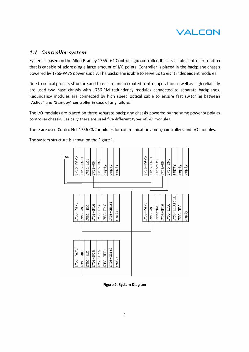
1.1 Controller system
System is based on the Allen-Bradley 1756
that is capable of addressing a large amount of I/O points. Controller is placed in the backplane chassis
powered by 1756-PA75 power supply. The backplane is able to serve up to eight independent modules.
Due to critical process structure
are used two base chassis with 1756
Redundancy modules are connected by high speed optical cable to ensure fast sw
“Active” and “Standby” controller
The I/O modules are placed on three separate backplane chassis powered by the same power supply as
controller chassis. Basically there
There are used ControlNet 1756
The system structure is shown on the
1
Bradley 1756-L61 ControlLogix controller. It is a scalable controller solution
that is capable of addressing a large amount of I/O points. Controller is placed in the backplane chassis
PA75 power supply. The backplane is able to serve up to eight independent modules.
s structure and to ensure uninterrupted control operation as well as
are used two base chassis with 1756-RM redundancy modules connected to
Redundancy modules are connected by high speed optical cable to ensure fast sw
“Active” and “Standby” controller in case of any failure.
The I/O modules are placed on three separate backplane chassis powered by the same power supply as
Basically there are used five different types of I/O modules.
Net 1756-CN2 modules for communication among controllers and I/O modules.
The system structure is shown on the Figure 1.
Figure 1. System Diagram
scalable controller solution
that is capable of addressing a large amount of I/O points. Controller is placed in the backplane chassis
PA75 power supply. The backplane is able to serve up to eight independent modules.
uninterrupted control operation as well as high reliability
RM redundancy modules connected to separate backplanes.
Redundancy modules are connected by high speed optical cable to ensure fast switching between
The I/O modules are placed on three separate backplane chassis powered by the same power supply as
CN2 modules for communication among controllers and I/O modules.

2
1.1.1 1756-EN2T module specification
The module is using the Ethernet Industrial (EtherNet/IP) network protocol which is industrial-
networking standard that supports both real-time I/O messaging and message exchange. The
EtherNet/IP network uses off-the-shelf Ethernet communication chips and physical media.
Specification:
• EtherNet/IP communication rate - 10/100 Mbps
• Logix communication connections - 256
• TCP/IP communication connections - 128
1.1.2 1756-L61 controller specification
Feature 1756-L61
Controller tasks 32 tasks
100 programs/tasks
Event tasks: all event triggers
Built-in communication ports RS-232 serial
Communicating options EtherNet/IP
ControlNet
DeviceNet
Data Highway Plus
Remote I/O
SynchLink
Third-party process and device networks
Serial port communication ASCII
DF1 full/half-duplex
DF1 radio modem
DH-485
Modbus via logic
Controller connections supported Max 250
Controller redundancy Full support
Attribute
User memory 2 MB
I/O memory 478 kB
Digital I/O Max 128 000
Analog I/O Max 4000
Total I/O Max 128 000

3
1.1.3 1756-RM redundancy module specification
Modules are used for establish redundancy between a pair of controller chassis without additional
programming and transparent to any devices connected over network. The primary controller chassis
automatically determines what data changes during its scan and sends that data to the secondary
controller.
• Reduce switchover times to as little as 20 ms
• Reduce ControlLogix footprint to a single slot
• Use CIP Time Synchronization with the 1756-EN2T in local redundant chassis
• Increase communication capacity with support for multiple ControlLogix L6x controllers and
ControlLogix 1756-CN2B
1.1.4 1756-CN2 ControlNet module specification
ControlLogix ControlNet communication modules bridge ControlNet links to route messages to devices
on other networks. The modules also monitor and control I/O modules located remotely from the
ControlLogix controller.
ControlNet module provides:
• High-speed I/O bridge functionality to manage distributed I/O modules
• Transfer of scheduled data via produced/consumed tags
• Unscheduled MSG instruction communication with other ControlNet nodes
• Messaging data for configuration and programming information, operator interfaces,
upload/download
1.1.5 1756 I/O modules
1756-HSC module
The module counts pulses by using a Counter or Frequency operational mode. The counts are presented
as either ‘accumulated count’ or ‘frequency’ depending on the mode that is configured for the module.
Pulse count values can be calculated by using different types of Counter and Frequency modes. The
simple counter uses only input A to count pulses. An encoder uses both input A and input B to count
pulses. The relationship between the two channels is how the encoder determines if the count is
positive (clockwise) or negative (counterclockwise).
• Number of counters – 2
• Number of outputs – 4
• Inputs per counter – 3

4
Input frequency (max): 1 MHz in Counter mode
500 kHz in Rate Measurement mode
250 kHz in Encoder mode
Count range: 0…16.777.214
IF/OF modules
Basic features: on-board data alarming, scaling to engineering units, real-time channel sampling
Data format: integer mode (left justified)
Conversion method: sigma-delta
1756-IF16 module
Inputs: 16 single ended, 8 differential or 4 differential (high speed)
Input range: ±10.5V, 0…21 mA
Resolution: 16 bits (10.5V: 343 µV/bit; 0…21 mA: 0,34 µA/bit)
1756-OF8 module
Outputs: 8 voltage or current
Output range: ±10.4V, 0…21 mA
Resolution: 15 bits (across 21 mA – 650 nA/bit; 10,4 V – 320 µV/bit)
IB/OB modules
Basic features: variety of voltage interface capabilities, point-level output fault states, direct-connect or
rack-optimized communication, field-side diagnostics
1756-IB16 module
Inputs: 16 (8 points/group)
Voltage category: 12/24 V DC sink
Operating voltage range: 10 … 31,2 V DC
Digital filter, off to on: 0,1, or 2 ms
1756-OB16I module (Isolated output module)
Outputs: 16 individually isolated
Voltage category: 12/24 V DC sink/source
Operating voltage range: 10 … 30 V DC
Output delay, off to on: 1 ms
5
1756-OB16ISOE module (sequence of events input module)
Inputs: 16 individually isolated, sequence of events
Voltage category: 24/48 V DC sink/source
Operating voltage range: 10 … 55 V DC
Digital filter, off to on: 0 … 50 ms
1.2 Valve positioner system
The valve positioner system is based on MOOG M3000 automation system. The system is consists of
programmable controller (Moog Servo Controller – MSC), software (Mood Axis Control Software -
MACS) and components (servomotors, servo-drives, servo-valves, etc.)
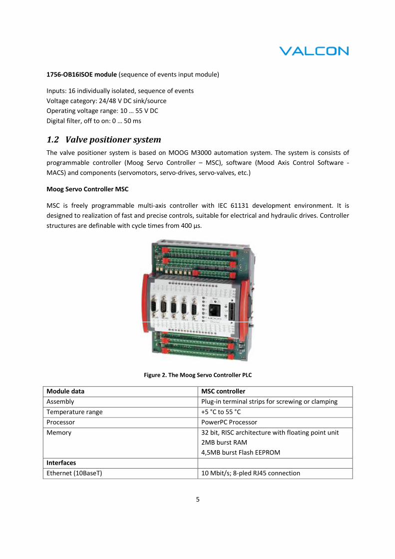
Moog Servo Controller MSC
MSC is freely programmable multi-axis controller with IEC 61131 development environment. It is
designed to realization of fast and precise controls, suitable for electrical and hydraulic drives. Controller
structures are definable with cycle times from 400 µs.
Figure 2. The Moog Servo Controller PLC
Module data MSC controller
Assembly Plug-in terminal strips for screwing or clamping
Temperature range +5 °C to 55 °C
Processor PowerPC Processor
Memory 32 bit, RISC architecture with floating point unit
2MB burst RAM
4,5MB burst Flash EEPROM
Interfaces
Ethernet (10BaseT) 10 Mbit/s; 8-pled RJ45 connection

6
2 independent CAN interfaces 10 kBit/s to 1 Mbit/s (adjustable)
>>WCAN<< WideCan: 2 Sub-D >>WCAN<< connectors
LocalCAN LocalCAN: in the side E-bus socket
>>MACS<< on front cover Communication with the MACS software on the PC
>>SIO<< on front cover For free use in the application program
Extension bus (E-bus) Connectors on right and left of module for
connecting up to 7 additional M3000 modules.
Digital inputs/outputs
Voltage supply of the digital I/O 24 V DC (18-32 V DC) SELV pursuant to IEC 61131-2
Current consumption of the digital I/O 0,3 A in idling; all outputs active: 4 A
8 digital inputs and outputs Individually configurable in MACS as input or
output.
Inputs: type 1 (current-consuming) pursuant to IEC
61131-2
Outputs: max. 0.5 A
Sustained short-circuit protected
Watchdog output Signalizes readiness for operation of the analog
and digital outputs.
Analog Inputs/Outputs
Voltage supply to analog I/O Internal via a DC/DC converter
8 analog inputs 16 Bit; individually configurable in the MACS
software as ±10 V, ±10 mA or 4–20 mA;
overvoltage protection up to ±40 V
2 analog outputs 16 Bit; each ±10 V, additionally individually
configurable in the MACS software as ±10 mA, ±50
mA or 4–20 mA
Overvoltage protection up to ±40 V; sustained
short-circuit protected
MOOG D633 servo control valves
The D633 is Direct Drive Valve (DDV) with electric closed spool position control. Valve is throttle valve
for 3-, 4-, and 2x2-way applications. It is suitable for electrohydraulic position, velocity, pressure or force
control systems including those with high dynamic response requirements.
The spool drive device is a permanent magnet linear force motor which can actively stroke the spool
from its spring centered position in both directions. This is an advantage compared with proportional
solenoids with one force direction only. The closed loop spool position electronics and pulse width
modulated (PWM) drive electronics are integrated into the valve.

7
Figure 3. Servo Control Valve Schematics
Micropulse transducers
There are used Balluff BTL5-E Profile for detection of the actual position of valves. Balluff Micropulse
transducers in the Profile housing are an alternative to linear transducers such as potentiometers, glass
scales, and LVDTs. The linear sensing element is protected in an aluminum extrusion.
The measuring point along the sensing element (waveguide) is indicated by a passive marker (magnet),
which needs no power.
Specification:
• Output - Potential-free
• Output current – 4 ... 20 mA
• Hysteresis - ≤ 4 µm
• Sampling rate - fSTANDARD = 1 kHz
Figure 4. Balluff Micropulse Transducers
Valve connector
Spool
Integrated
electronic
Position
transducer
Bushing
Linear force
motor
Centering
spring

A whole valve positioner system is shown on the
1.3 Turbine rotation speed sensors
The RPM Transducer PR 9376 is ideally suited for contactless measurement of rotational frequency of
ferromagnetic machinery components. Universal design, simple mounting and excellent
enable it to be used in a wide range of applications.
Due to high resolution, fast internal electronic and the sharp edged output pulses the PR 9376 is suitable
for measurement of extremely high as well as very low rotational speeds with high resolution.
The head of PR 9376 is a differential sensor consisting
which are connected in series and mounted above a small permanent magnet. Two resistors of the
transducer- electronic part complete this configuration into a Wheatstone Bridge which controls a
following DC-switching amplifier with fast push
8
A whole valve positioner system is shown on the Figure 5.
Figure 5. Positioning System Diagram
Turbine rotation speed sensors
ducer PR 9376 is ideally suited for contactless measurement of rotational frequency of
ferromagnetic machinery components. Universal design, simple mounting and excellent
enable it to be used in a wide range of applications.
Due to high resolution, fast internal electronic and the sharp edged output pulses the PR 9376 is suitable
high as well as very low rotational speeds with high resolution.
The head of PR 9376 is a differential sensor consisting of two magneto sensitive
which are connected in series and mounted above a small permanent magnet. Two resistors of the
electronic part complete this configuration into a Wheatstone Bridge which controls a
amplifier with fast push-pull short circuit proof output.
ducer PR 9376 is ideally suited for contactless measurement of rotational frequency of
ferromagnetic machinery components. Universal design, simple mounting and excellent characteristics
Due to high resolution, fast internal electronic and the sharp edged output pulses the PR 9376 is suitable
high as well as very low rotational speeds with high resolution.
semiconductor resistors
which are connected in series and mounted above a small permanent magnet. Two resistors of the
electronic part complete this configuration into a Wheatstone Bridge which controls a

9
Specification:
• Principle measurement - Differential magnetic field sensor
• Triggering - Contactless by mechanical trigger marks
• Trigger frequency range – 0 … 20 kHz
• Output - Short circuit proof push-pull output stage
• Output pulse voltage – HIGH 10 V, LOW 1 V
• Pulse rise and fall time - < 1 µs
Figure 6. Rotation Speed Sensors
1.4 Control logic
According to used hardware solution there is a used RSLogix 5000 software for design and configuration.
Logix technology offers a unique approach — one control platform using a common control engine with
a common development environment.
The logic is divided into 5 tasks according to control option:
- Control Logic (main program)
- Load Loop
- Pressure Loop
- Speed Loop
- Valve control

10
1.4.1 Control Logic
It consists of 18 separate control sheets.
S05_TC_mjerenja:
Related inputs – MW measurement, Pressure setpoint from LDC, throttle pressure (and signal quality),
LDC output MW, control oil pressure (and signal quality)
Related outputs – active power > 30 MW, active power < 10 MW, active power, pressure setpoint value
from LDC, throttle pressure, throttle pressure measurement failed, load setpoint value from LDC
S06_SPEED_MED_SEL_OVERSPEED_SETPOINTS:
Related inputs – turbine rotor rotation speed, speed measurement failed, valve position frequency
limiter, mechanical over speed test
Related outputs – speed sensor manual request, turbine rotation speed, close cv protection setpoint,
turbine over speeded, turbine speed in limits, over speed protection setpoint, mechanical turbine over
speed, speed measurement failed
S08_MUT_control_logic:
Related inputs – turbine latched/not latched, IP stop valve opened/closed, HP stop valve opened/closed,
open safety valves, external TG protection, close safety valves, MUT ready/opened/closed
Related outputs – HP SV not opening/closing, IP SV not opening/closing, all safety valves are opened,
MUT open/close command
S09_TC_DUMP_CV_LOGIC:
Related inputs – active power > 30 MW, generator synchronized, turbine latched/not latched, turbine
over speeded, block speed protection over speed test, external TG protection, speed measurement
failed
Related outputs – overload protection, over speed protection, HP valve PLW, IP valve PLW, bypass valve
PRA, valve position frequency limiter
S10_TC_PROTECTIONS:
Related inputs – turbine valves contingency, external turbine protection, boiler protection, off turbine
safety valves, mechanical turbine over speed, speed measurement failed, speed sensor manual request,
generator synchronized, acknowledge turbine protection, TG trip reason
Related outputs – external TG protection, TG trip is active, open turbine solenoid command, TG trip
reason
S11_Turbine_latched_logic:
Related inputs – generator breaker on, control oil pressure to safety valves is OK
Related outputs – generator synchronized/not synchronized, turbine latched/not latched
S12_OVER_SPEED_TEST_LOGIC:
Related inputs – on/off over speed test, generator synchronized, external TG protection
Related outputs – block speed protection over speed test

11
S19_AUTO_SYNCHRONIZATION_LOGIC:
Related inputs – on/off auto synchronization, turbine in manual control, generator synchronized,
turbine speed > 2950 rpm, synchronization request more rpm, increase/decrease pushbutton for
synchronization
Related outputs – auto synchronization on, auto synchronization is valid, synchronizer
increase/decrease
S20_TURBINE_MANUALAUTO_LOGIC:
Related inputs – TP loop on/off, speed loop on, turbine in auto, turbine latched, HP/IP governor in
manual, speed loop selected, turbine to manual, HP valves contingency, IP or LPBP valves contingency,
mechanical turbine over speed, generator synchronized, turbine latched, manual reject HP/IP governor
Related outputs – turbine in auto/manual, manual reject HP/IP governor, HP/IP valves in auto, initial
MW pickup, turbine valves contingency, engage SP loop, engage LDC loop, engage MW loop, engage TP
loop
S21_OVERSPEED_SELECTION_LOGIC:
Related inputs – engage SP loop, generator synchronized, speed loop on, speed measurement failed,
speed loop off, open loop on, block speed protection over speed test, mechanical turbine speed test,
turbine not latched
Related outputs – speed loop selected, selected loop interlock, mechanical over speed test, mechanical
and el. Over speed test is not active, electrical test turbine speed is not active, electrical test turbine
speed
S22_SPEED_LOOP_SELECTION_LOGIC:
Related inputs – select SP setpoint, new speed demand is not valid, auto synchronization on, speed
setpoint in resonance range, new speed rate out of limits, select SP rate, generator synchronized, speed
controller is tracking valve position, generator synchronized, external TG protection, turbine not latched,
speed delta > 50 rpm, turbine in manual control
Related outputs – new speed setpoint is not valid, new speed setpoint enabled, wrong speed rate
selection, new speed rate enabled, speed SP is tracking
S23_SPEED_LOOP_SELECTION:
Related inputs – turbine speed > 3000 rpm, turbine in manual control, turbine speed in limits, hold over
speed test, mechanical and electrical over speed test is not active, speed SP is tracking, speed demand is
changing, select SP setpoint, speed loop selected, hold changes pushbutton, auto synchronization on, go
to change, speed in resonance range, block speed protection over speed test, engage over speed test,
over speed protection, turbine not latched, generator not synchronized
Related outputs – speed controller is tracking valve position, hold changes, close valves

12
S24_MW_LOOP_LOGIC:
Related inputs – generator not synchronized, MW loop selected, MW controller is tracking valve
position, MW delta in limits, hold changes pushbutton, select MW setpoint, go to change, boiler
runback, turbine remote control
Related outputs – MW controller is tracking PV, hold MW changes
S25_MW_LOOP_LOGIC:
Related inputs – turbine in manual control, MW delta high limit active, generator not synchronized, MW
loop selected, select MW setpoint, MW rate out of limits, select MW rate,
Related outputs – MW controller is tracking valve position, enter MW setpoint from keyboard, enter
MW rate enabled
S26_REMOTE_LOOP_SELECTION:
Related inputs – LDC in auto mode, generator synchronized, remote control on/off, MW loop selected,
engage LDC loop, open loop on, LDC MW output demand quality, LDC does not track LDC in BF, boiler
follow mode, coordinate control – boiler follow mode, turbine remote control, MW loop on, TP loop
selected, MW loop off, turbine follow mode, TP demand is not valid
Related outputs – turbine remote control, select MW loop interlock, MW loop on
S27_TP_RATE_SELECTION_LOGIC:
Related inputs – select TP rate, operator entered setpoint/TP rate in limits, select TP setpoint, TP loop
selected, hold changes pushbutton, TP demand is changing, go to change, take nominal parameters,
turbine remote control
Related outputs – new setpoint/TP rate enabled, TP controller is tracking PV, hold TP changes
S28_LOOPS_SELECTION_LOGIC:
Related inputs – TP loop off, turbine remote control, coordinate control boiler follow mode, engage MW
loop, open loop on, engage LDC loop, LDC base mode, TP loop on, turbine follow mode, boiler runback,
active power < 10 MW, boiler follow mode, throttle pressure measurement failed, MW loop on
Related outputs – MW loop selected, TP loop selected, on TP loop entry rate selected, selected TP loop
interlock
S29_OPEN_LOOP_LOGIC:
Related inputs – on open loop, turbine speed rotation speed, generator synchronized, turbine in auto,
speed loop selected, TP loop selected, turbine valves contingency, turbine over speeded, turbine not
latched, MW loop on, turbine in manual control, turbine remote control, open loop on, go to change,
select open loop interlock, hold changes pushbutton, open loop demand is changing
Related outputs – open loop on, select open loop interlock, go to change valve position

13
1.4.2 Load Loop
It is consists of 3 separate control sheets. The logic of this loop is used for turbine control when running
in load loop.
S45_MW_Loop_Setpoint_Rate_Memory:
Related inputs – initial MW setpoint, initial MW pickup, MW loop selected, MW loop on, turbine remote
control, select MW rate, turbine remote control, runback limit, active power, MW controller is tracking
PV, enter MW rate enabled, runback rate, TG runback load limit enabled, generator synchronized, hold
MW changes
Related outputs – LDC does not track LDC in BF, MW demand in memory, MW rate out of limits, MW
rate in memory, MW rate
S46_MW_Loop_Output:
Related inputs – MW rate, MW controller is tracking PV, MW demand in memory, initial pickup,
frequency corrector, active power
Related outputs – MW reference demand, MW delta high limit active, MW delta in limits, MW loop
delta
S47_MW_Loop_Demand:
Related inputs – throttle pressure, valve position setpoint, MW reference demand, active power, MW
loop on, generator synchronized, MW loop selected, open loop on, MW controller is tracking valve
position
Related outputs – initial MW setpoint, MW loop valve position demand
1.4.3 Pressure Loop
It is consists of 2 separate control sheets. The logic is used when turbine operates in pressure loop.
S55_TP_Setpoint_Rate_Memory:
Related inputs – select TP setpoint/rate, take nominal parameters, new TP setpoint/rate enabled,
pressure sepoint value from LDC, turbine remote control, boiler follow mode, TP controller is tracking
PV, on TP loop entry rate selected, turbine remote control, hold TP changes
Related outputs – select TP setpoint, operator entered setpoint/rate is in limits, TP demand in memory,
TP rate in memory, TP rate value
S56_TP_Setpoint_Calculation:
Related inputs – TP rate value, TP controller is tracking PV, engage TP loop, active power, throttle
pressure, TP demand in memory, valves position setpoint, TP loop selected,
Related outputs – TP demand is changing, TP loop delta, TP loop valve position demand, TP reference

14
1.4.4 Speed Loop
It is consists of 5 separate control sheets. The loop is providing logic when turbine is operating in speed
loop mode.
S30_RESONANCE_RANGES_CALCULATING:
Related inputs – turbine speed rotation speed, speed reference, generator synchronized, speed, in
resonance range
Related outputs – resonance range calculator output, speed in resonance range, resonance range 1 - 4
S32_FREQUENCY_CORECTION:
Related inputs – turbine rotation speed, MW loop on, primary control ON/OFF pushbutton
Related outputs – frequency corrector, frequency corrector to LDC, turbine speed > 2970
S35_Speed_Setpoint_Rate_Memory:
Related inputs – synchronizer increase/decrease, mechanical over speed test is not active, electrical
turbine speed is not active, new speed setpoint enabled, generator synchronized, speed SP is tracking,
resonance range calculator output, select SP setpoint, select SP rate, new speed rate enabled, auto
synchronization on, mechanical and electrical over speed test is not active, hold changes,
Related outputs – speed rate in memory, speed loop rate, new speed rate out of limits, speed demand
in memory, new speed demand is not valid, speed setpoint in resonance range, setpoint in resonance
range 3
S36_Speed_Setpoint_calculation:
Related inputs – speed loop rate, speed in resonance range, speed SP is tracking, speed demand in
memory, turbine rotation speed
Related outputs – speed demand is changing, speed delta > 50 rpm, SP loop delta, speed reference
S37_Speed_Loop_Demand:
Related inputs – throttle pressure, IP/HP governor in manual, speed controller is tracking valve position,
turbine rotation speed, speed reference, valves position setpoint, close valves
Related outputs – speed loop valve position demand
1.4.5 Valve Control
It is consists of 6 separate control sheets. The loop is providing logic for valve control.
S32_LPBP_Valves_Control:
Related inputs – IP valves position setpoint
Related outputs – LPBP valves position setpoint

15
S60_Loop_Selection:
Related inputs – turbine valves contingency, turbine over speeded, valves position setpoint, open loop
reference, speed loop valve position demand, speed loop selected, MW loop valve position demand, TP
loop valve position demand, MW loop selected, TP loop selected, open loop on, turbine in auto, open
loop rate in memory, go to change valve position, open loop on, valve position loop delta, valves
position setpoints, open loop demand in memory, open loop reference
Related outputs – open loop demand in memory, open loop delta, open loop demand is changing, open
loop reference, valve position loop delta, valve position demand
S61_ HP_IP_Valves_Output:
Related inputs – turbine latched/not latched, open loop on, turbine in manual control, TG trip is active,
valve position demand, turbine rotation speed, block speed protection over speed test, valve position
frequency limiter, valves position set point, IP valves to auto, manual reject IP governor, IP governor to
auto/manual, HP valves to auto, manual reject HP governor, HP governor to auto/manual
Related outputs – IP valves position setpoint, IP governor in manual, HP valves position setpoint, HP
governor in manual, valves position setpoint, IP/HP mastation track
S62_ HP_Valves_Output:
Related inputs – HP valve #1 – 7 measurement # 1 – 2, HP valves position setpoint, Moog valve HP #1 – 7
ready, TP #1 – 2 HP valve #1 – 7 ready, MCS #1 – 2 ready
Related outputs – HP valve #1 – 7 selected position measurement, contingency HP valve #1 – 7, HP valve
#1 – 7 setpoint and electrical error HP valve #1 - 7
S64_LPBP_Valves_Output:
Related inputs – IP valve #1 – 2 position measurement #1 – 2, IP valves position setpoint, Moog valve IP
#1 – 2 ready, TP #1 - 2 IP valve #1 – 2 ready, MSC #5 - 6 ready, LPBP valve #1 – 2 position measurement
#1 -2, LPBP valves position setpoint, Moog valve BV #1 – 2 ready, TP #1 – 2 BV #1 – 2 ready
Related outputs – IP valve #1 – 2 position measurement, contingency IP valve #1 – 2, IP valve #1 – 2
position, electrical error IP valve #1 – 2, LPBP valve #1 – 2 selected position measurement, contingency
LPBP valve #1 – 2, LPBP valve #1 – 2 position setpoint, electrical error LPBP valve #1 - 2
S65_Valves_Contingency:
Related inputs – electrical error HP valve #1 – 7, electrical error IP valve #1 – 2, electrical error LPBP
valve #1 - 2
Related outputs – HP valves contingency, IP or LPBP valves contingency

16
1.5 Operator interface
Figure 7. Main Graphic Window
The main operator graphic window is shown on the Figure 7. All important process information is visible
on the main graphic.
The window is divided into 11 parts according to scope of control. Only one part can be managed at the
same time.
1.5.1 Header
Figure 8. Header of Main Window
On the header part you can find two pushbuttons and one information area. The pushbutton 1 is
opening new window „measuring and power supply“ (Figure 99). The pushbutton 2 is opening new
window „trends“ (10). The information area contains time stamp information.
Pushbutton 1
Pushbutton 2
Time and date

17
Figure 9. Measuring and Power Supply Window
Figure 10. Trends Window

18
1.5.1.1 Measuring and power supply window
The graphic window is designed to provide online monitoring of:
• actual position of valves (HP, IP, BP, MUT) [%]
• valves setpoint [%]
• Moog valves position [%] (and power supply – red color means out of order)
• Oil pressure on MUT valve [bar]
• Oil filter state (red color means replace)
• Level of oil in tank [mm]
• power supply state (red color means out of order)
• Active power [MW]
• Steam pressure [bar]
• Actual turbine rotation speed [rpm]
Figure 11. Valve Information
Figure 12. MUT Valve
Valve setpoint
Moog valve position
Valve actual position
Moog controler
power state
Oil filter state
MUT power supply
Oil pressure

19
Figure 13. Oil Level
Figure 14. Power Supply State
Figure 15. Active Power, Steam Pressure, Turbine Rotation Speed
There is a pushbutton “GLAVNI PANEL” to return back to the main window.
Oil filter state
Oil level
Active power Steam pressure Turbine rotation speed

20
1.5.1.2 Trends window
The window is providing time behavior selected variables and theirs setpoints:
• Active power
• Steam pressure
• Turbine rotation speed
• Valve position
1.5.2 High/Intermediate pressure valves control
To activate the control field, there is necessary to press the „Ventili CVP“/”Ventili CSP” button first. Even
if the area is not activated there are visible actual information about the setpoint and real value. This
information is interpreted by both bar chart for review and exact value.
Figure 16. HP Valve Control
Activation button
Setpoint value Real value
Actual controller state
AUTO pushbutton MANUAL pushbutton
Increase setpoint
Decrease setpoint

21
To change controller state from/to “AUTO”/”MANUAL” use appropriate pushbutton. When the
“MANUAL” mode is active a two pushbuttons are active as well. These pushbuttons are used to
increase/decrease setpoint value.
1.5.3 Regulation options
After activation this area you are able to choose the regulation scheme:
• Speed loop
• Open loop
• Pressure loop
• Load loop
The availability of desired regulation is depends on the current turbine state. When the field on the left
side of the area is green colored the scheme is available. When the color is red the conditions for
regulation are not met.
Figure 17. Regulation Options
1.5.4 Regulation setpoint
The area is closely associated with the previous „Regulation options“ area. When active you are able to
setup setpoint and rate for related regulation.
Figure 18. Regulation Setpoint
Activation button
Speed loop selection
Open loop selection
Pressure loop selection
Load loop selection
Regulation available
Regulation not available
Activation button
Start button
Stop button
Setpoint value
Rate value
Entering fiels
Validation button

22
After mouse click into enabled entering field new window is populated (Figure 19). By mouse click on
specified number the new value is created. To correct the entered value you can use the “Backspace”
button. By click on the “OK” button the new value is entered to the specified regulation setpoint/rate
area. To validate the new value press the button next to the new value.
Figure 19. Setpoint Value Window
When the entering of the new values is finished the “Start” button need to be pressed (note: when rate
value is changed only, no need to press the “Start” button).
1.5.5 Notification area
The area contains both the information fields and control fields as well. The basic information about
turbine rotation speed, steam pressure, active power and actual regulation state are available. There is
ability to slightly change actual value of variable according to selected regulation.
Figure 20. Notification Area
Increase button
Decrease button
23
1.5.6 Turbine trip notification area
When turbine is going to trip for some reason, you can find it in this part of main graphic window. As
shown on the Figure 2121 there are seven options for turbine trip. No other operation is possible until
the acknowledge button is pressed.
Figure 21. Turbine Trip Information
If there is more than one turbine trip condition met only the first one is signalized by red color. Rests of
them are signalized by green color.
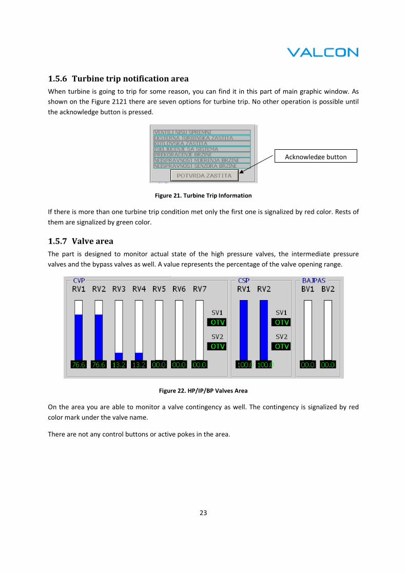
1.5.7 Valve area
The part is designed to monitor actual state of the high pressure valves, the intermediate pressure
valves and the bypass valves as well. A value represents the percentage of the valve opening range.
Figure 22. HP/IP/BP Valves Area
On the area you are able to monitor a valve contingency as well. The contingency is signalized by red
color mark under the valve name.
There are not any control buttons or active pokes in the area.
Acknowledge button
24
1.5.8 Auto/Manual option
This area is used to select between turbine regulation mode – “automatic” and “manual”. Actual
regulation mode is signalized by the text field below the activation button.
Figure 23. Auto/Manual Area
At the bottom part of the area there are MUT control push buttons. You can open or close MUT valve
automatically by pressing the “Start” button or “STOP” button respectively. The notification arrow
shows which direction of moving is activated. Greed colored arrow means opening; red colored is used
for closing.
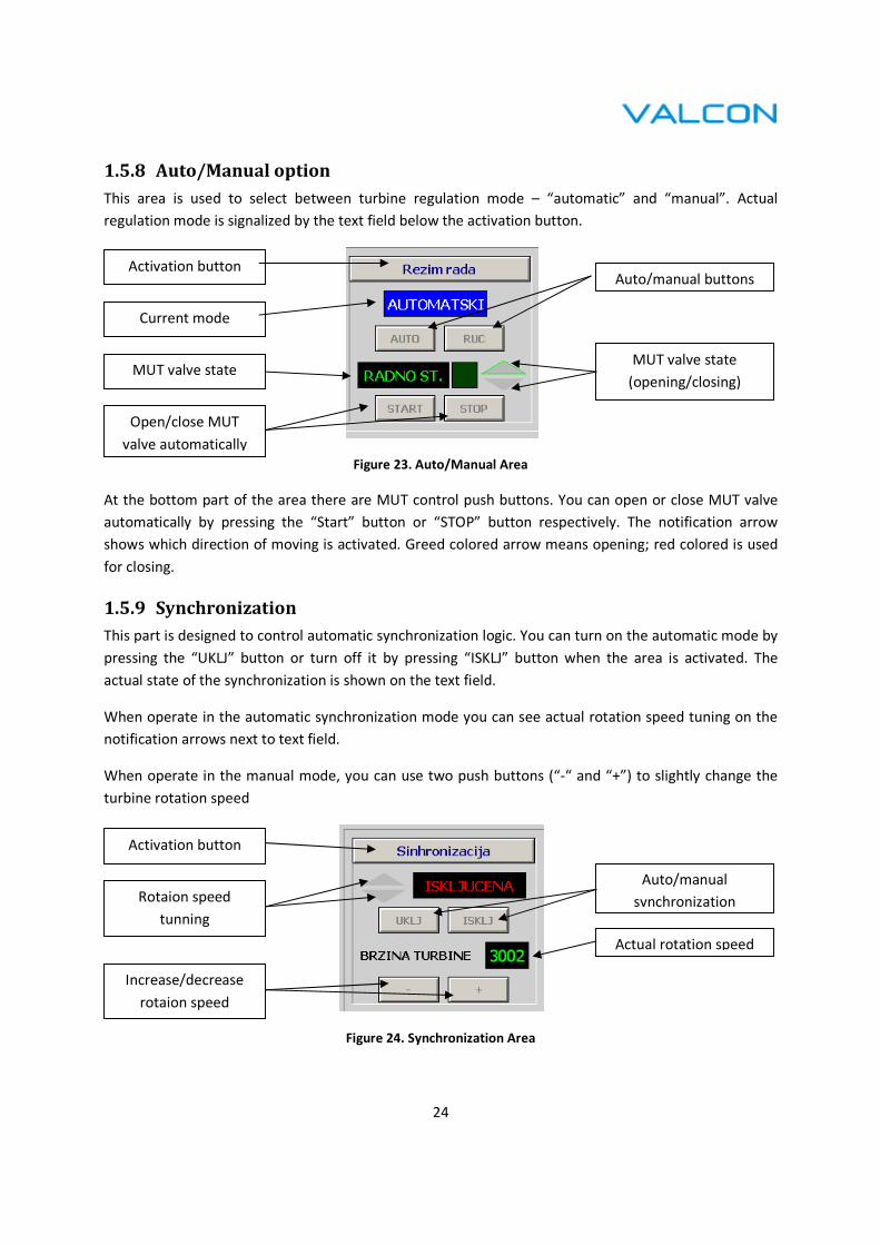
1.5.9 Synchronization
This part is designed to control automatic synchronization logic. You can turn on the automatic mode by
pressing the “UKLJ” button or turn off it by pressing “ISKLJ” button when the area is activated. The
actual state of the synchronization is shown on the text field.
When operate in the automatic synchronization mode you can see actual rotation speed tuning on the
notification arrows next to text field.
When operate in the manual mode, you can use two push buttons (“-“ and “+”) to slightly change the
turbine rotation speed
Figure 24. Synchronization Area
Activation button
Current mode
Auto/manual buttons
MUT valve state
Open/close MUT
valve automatically
MUT valve state
(opening/closing)
Activation button
Rotaion speed
tunning
Actual rotation speed
Auto/manual
synchronization
Increase/decrease
rotaion speed

25
1.5.10 Turbine testing
After activation of this part of the main graphic windows you can perform two turbine tests. To start a
testing there is necessary to choose what test you want to start and then press the “Kreni” button. To
cancel the active test the “Stani” button need to be pressed.
Figure 25. Test Area
The turbine rotation speed limits for the regulation valves and the stop valves are show on the area at
the bottom part.
In the bottom part of the area there is button to manual unlatch the turbine (force trip).
1.5.11 Error log
The log area contains all communication information between the controller and the graphic. When
some error or alarm occurs you can find it in the log window.
Figure 26. Log Area
Error/alarm messages are red colored in contrast to the normal communication which is blue colored
(log 0) or black colored (log 1).
To open a detailed survey of the communication the open log button need to pressed.
Activation button
Mechanical test
button
Electrical test button
Start/stop button
Rotation speed
limits
Unlatch button
Open log window
Acknowledge alarm

26
Figure 27. Log Window