tunnelling by epb tunnel boring machine in dmrc
DESCRIPTION
EPB machineTRANSCRIPT
LOGIN CREATE AN ACCOUNT (/component/comprofiler/registers.html)HOME (/) ABOUT US (/aboutus.html) CONTACT US (/contactus.html) ADVERTISE WITH US (/advertisewithus.html)
(/component/banners/click/183.html)(/)
Search...
(/component/banners/click/98.html)
(/component/banners/click/177.html)
Currently Online
We have 154 guests andno members online
(http://www.alexa.com/data/details/main?url=http://www.nbmcw.com)(http://www.alexa.com/siteinfo/www.nbmcw.com)
MAGAZINES NEWS (/news.html) ARTICLES PRODUCTS EQUIPMENTS REPORTS INTERVIEWS (/interviews.html)
SUBSCRIPTION (/subscription/levels.html) PEOPLE WATCH (/peoplewatch.html) EVENTS (/events.html)
(/component/banners/click/14.html)
View Online(http://nbmcw.com/Online_Edition/NBMCW/June
2015/index.htm)Download Latest Issue
(http://nbmcw.com/index.php?option=com_ars&view=download&id=167)
Previous Issues(http://nbmcw.com/index.php?option=com_content&view=article&id=32475:nbmcw
archives2014&catid=9:nbmcwissue
archive&Itemid=216)
View Online(http://nbmcw.com/Online_Edition/MGS/June
2015/index.htm)Download Latest Issue
(http://nbmcw.com/index.php?option=com_ars&view=download&id=168)
Previous Issues(http://nbmcw.com/index.php?option=com_content&view=article&id=32726:mgs
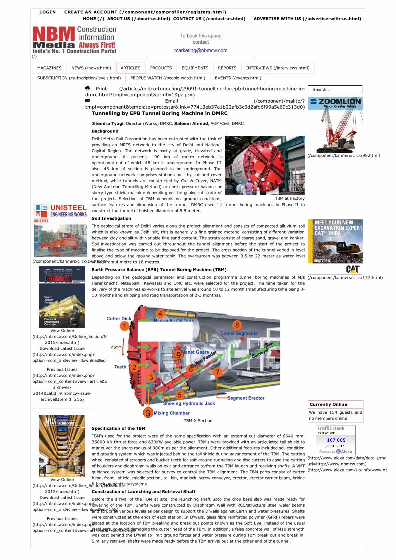
TBM at Factory
Tunnelling by EPB Tunnel Boring Machine in DMRC
Jitendra Tyagi, Director (Works) DMRC, Saleem Ahmad, AGM/Civil, DMRC
Background
Delhi Metro Rail Corporation has been entrusted with the task ofproviding an MRTS network to the city of Delhi and NationalCapital Region. The network is partly at grade, elevated andunderground. At present, 190 km of metro network isoperational out of which 48 km is underground. In Phase IIIalso, 45 km of section is planned to be underground. Theunderground network comprises stations built by cut and covermethod, while tunnels are constructed by Cut & Cover, NATM(New Austrian Tunnelling Method) or earth pressure balance orslurry type shield machine depending on the geological strata ofthe project. Selection of TBM depends on ground conditions,surface features and dimension of the tunnel. DMRC used 14 tunnel boring machines in PhaseII toconstruct the tunnel of finished diameter of 5.8 meter.
Soil Investigation
The geological strata of Delhi varies along the project alignment and consists of compacted alluvium soilwhich is also known as Delhi silt, this is generally a fine grained material consisting of different variationbetween clay and silt with variable fine sand content. The strata consist of coarse sand, gravel and kankar.Soil investigation was carried out throughout the tunnel alignment before the start of the project tofinalise the type of machine to be deployed for the project. The cross section of the tunnel varied in levelabove and below the ground water table. The overburden was between 3.5 to 22 meter as water levelvaried from 4 metre to 18 metres.
Earth Pressure Balance (EPB) Tunnel Boring Machine (TBM)
Depending on the geological parameter and construction programme tunnel boring machines of M/sHerenknecht, Mitsubishi, Kawasaki and OMC etc. were selected for the project. The time taken for thedelivery of the machines exworks to site arrival was around 10 to 12 month (manufacturing time being 810 months and shipping and road transportation of 23 months).
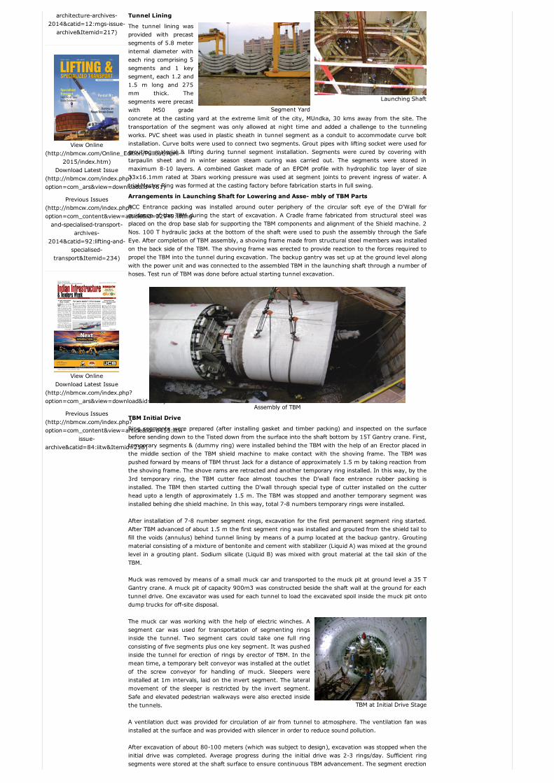
TBMX Section
Specification of the TBM
TBM's used for the project were of the same specification with an external cut diameter of 6640 mm,35000 KN thrust force and 630KW available power. TBM's were provided with an articulated tail shield tomaneuver the sharp radius of 300m as per the alignment. Other additional features included soil conditionand grouting system which was injected behind the tail shield during advancement of the TBM. The cuttingwheel consisted of scrapers and bucket teeth for soft ground tunneling and disc cutters to ease the cuttingof boulders and diaphragm walls on exit and entrance to/from the TBM launch and receiving shafts. A VMTguidance system was selected for survey to control the TBM alignment. The TBM parts consist of cutterhead, front , shield, middle section, tail kin, manlock, screw conveyor, erector, erector carrier beam, bridge& back up gantries/systems.
Construction of Launching and Retrieval Shaft
Before the arrival of the TBM at site, the launching shaft upto the drop base slab was made ready forlowering of the TBM. Shafts were constructed by Diaphragm Wall with RCC/structural steel waler beamsand struts at various levels as per design to support the D'walls against Earth and water pressures. Shaftswere constructed at the ends of each station. In D'walls, glass fibre reinforced polymer (GFRP) rebars wereplaced at the location of TBM breaking and break out points known as the Soft Eye, instead of the usualsteel bars, to avoid damaging the cutter head of the TBM. In addition, a false concrete wall of M10 strengthwas cast behind the D'Wall to limit ground forces and water pressure during TBM break out and break in.Similarly retrieval shafts were made ready before the TBM arrival out at the other end of the tunnel.
Print (/articles/metrotunneling/29091tunnellingbyepbtunnelboringmachineindmrc.html?tmpl=component&print=1&page=)M Email (/component/mailto/?tmpl=component&template=protostar&link=77413eb37a1b22afb3c0d2afd6f99a5e69c313d0)
architecturearchives2014&catid=12:mgsissuearchive&Itemid=217)
View Online(http://nbmcw.com/Online_Edition/Pullout/April
2015/index.htm)Download Latest Issue
(http://nbmcw.com/index.php?option=com_ars&view=download&id=161)
Previous Issues(http://nbmcw.com/index.php?option=com_content&view=article&id=32949:liftingandspecialisedtransport
archives2014&catid=92:liftingand
specialisedtransport&Itemid=234)
View OnlineDownload Latest Issue
(http://nbmcw.com/index.php?option=com_ars&view=download&id=169)
Previous Issues(http://nbmcw.com/index.php?option=com_content&view=article&id=6455:iitw
issuearchive&catid=84:iitw&Itemid=218)
TBM at Initial Drive Stage
Launching Shaft
Segment Yard
Tunnel Lining
The tunnel lining wasprovided with precastsegments of 5.8 meterinternal diameter witheach ring comprising 5segments and 1 keysegment, each 1.2 and1.5 m long and 275mm thick. Thesegments were precastwith M50 gradeconcrete at the casting yard at the extreme limit of the city, MUndka, 30 kms away from the site. Thetransportation of the segment was only allowed at night time and added a challenge to the tunnelingworks. PVC sheet was used in plastic sheath in tunnel segment as a conduit to accommodate curve boltinstallation. Curve bolts were used to connect two segments. Grout pipes with lifting socket were used forgrouting material & lifting during tunnel segment installation. Segments were cured by covering withtarpaulin sheet and in winter season steam curing was carried out. The segments were stored inmaximum 810 layers. A combined Gasket made of an EPDM profile with hydrophilic top layer of size33x16.1mm rated at 3bars working pressure was used at segment joints to prevent ingress of water. Atrial Master Ring was formed at the casting factory before fabrication starts in full swing.
Arrangements in Launching Shaft for Lowering and Asse mbly of TBM Parts
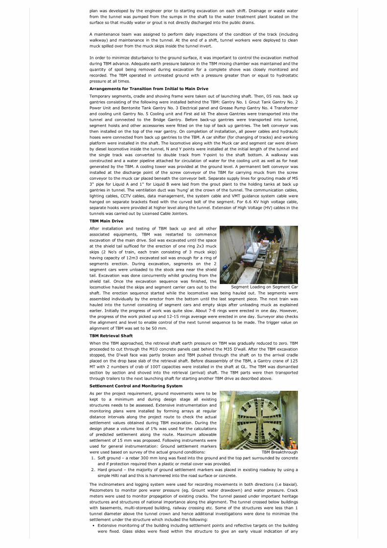
RCC Entrance packing was installed around outer periphery of the circular soft eye of the D'Wall forguidance of the TBM during the start of excavation. A Cradle frame fabricated from structural steel wasplaced on the drop base slab for supporting the TBM components and alignment of the Shield machine. 2Nos. 100 T hydraulic jacks at the bottom of the shaft were used to push the assembly through the SafeEye. After completion of TBM assembly, a shoving frame made from structural steel members was installedon the back side of the TBM. The shoving frame was erected to provide reaction to the forces required topropel the TBM into the tunnel during excavation. The backup gantry was set up at the ground level alongwith the power unit and was connected to the assembled TBM in the launching shaft through a number ofhoses. Test run of TBM was done before actual starting tunnel excavation.
Assembly of TBM
TBM Initial Drive
Ring segments were prepared (after installing gasket and timber packing) and inspected on the surfacebefore sending down to the Tisted down from the surface into the shaft bottom by 15T Gantry crane. First,temporary segments & (dummy ring) were installed behind the TBM with the help of an Erector placed inthe middle section of the TBM shield machine to make contact with the shoving frame. The TBM waspushed forward by means of TBM thrust Jack for a distance of approximately 1.5 m by taking reaction fromthe shoving frame. The shove rams are retracted and another temporary ring installed. In this way, by the3rd temporary ring, the TBM cutter face almost touches the D'wall face entrance rubber packing isinstalled. The TBM then started cutting the D'wall through special type of cutter installed on the cutterhead upto a length of approximately 1.5 m. The TBM was stopped and another temporary segment wasinstalled behing dhe shield machine. In this way, total 78 numbers temporary rings were installed.
After installation of 78 number segment rings, excavation for the first permanent segment ring started.After TBM advanced of about 1.5 m the first segment ring was installed and grouted from the shield tail tofill the voids (annulus) behind tunnel lining by means of a pump located at the backup gantry. Groutingmaterial consisting of a mixture of bentonite and cement with stabilizer (Liquid A) was mixed at the groundlevel in a grouting plant. Sodium silicate (Liquid B) was mixed with grout material at the tail skin of theTBM.
Muck was removed by means of a small muck car and transported to the muck pit at ground level a 35 TGantry crane. A muck pit of capacity 900m3 was constructed beside the shaft wall at the ground for eachtunnel drive. One excavator was used for each tunnel to load the excavated spoil inside the muck pit ontodump trucks for offsite disposal.
The muck car was working with the help of electric winches. Asegment car was used for transportation of segmenting ringsinside the tunnel. Two segment cars could take one full ringconsisting of five segments plus one key segment. It was pushedinside the tunnel for erection of rings by erector of TBM. In themean time, a temporary belt conveyor was installed at the outletof the screw conveyor for handling of muck. Sleepers wereinstalled at 1m intervals, laid on the invert segment. The lateralmovement of the sleeper is restricted by the invert segment.Safe and elevated pedestrian walkways were also erected insidethe tunnels.
A ventilation duct was provided for circulation of air from tunnel to atmosphere. The ventilation fan wasinstalled at the surface and was provided with silencer in order to reduce sound pollution.
After excavation of about 80100 meters (which was subject to design), excavation was stopped when theinitial drive was completed. Average progress during the initial drive was 23 rings/day. Sufficient ringsegments were stored at the shaft surface to ensure continuous TBM advancement. The segment erection
Segment Loading on Segment Car
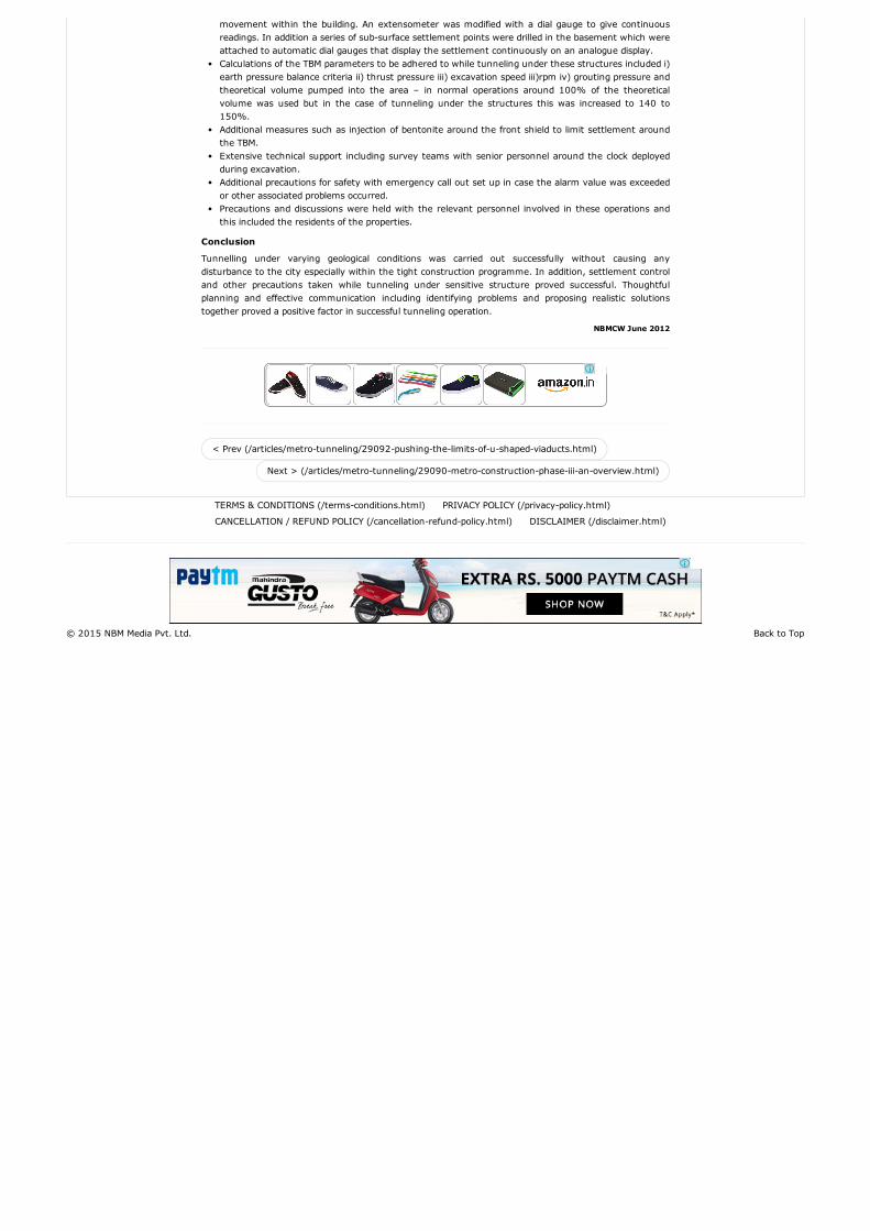
TBM Breakthrough
plan was developed by the engineer prior to starting excavation on each shift. Drainage or waste waterfrom the tunnel was pumped from the sumps in the shaft to the water treatment plant located on thesurface so that muddy water or grout is not directly discharged into the public drains.
A maintenance team was assigned to perform daily inspections of the condition of the track (includingwalkway) and maintenance in the tunnel. At the end of a shift, tunnel workers were deployed to cleanmuck spilled over from the muck skips inside the tunnel invert.
In order to minimize disturbance to the ground surface, it was important to control the excavation methodduring TBM advance. Adequate earth pressure balance in the TBM mixing chamber was maintained and thequantity of spoil being removed during excavation for a complete shove was closely monitored andrecorded. The TBM operated in untreated ground with a pressure greater than or equal to hydrostaticpressure at all times.
Arrangements for Transition from Initial to Main Drive
Temporary segments, cradle and shoving frame were taken out of launching shaft. Then, 05 nos. back upgantries consisting of the following were installed behind the TBM: Gantry No. 1 Grout Tank Gantry No. 2Power Unit and Bentonite Tank Gantry No. 3 Electrical panel and Grease Pump Gantry No. 4 Transformerand cooling unit Gantry No. 5 Cooling unit and First aid kit The above Gantries were transported into thetunnel and connected to the Bridge Gantry. Before backup gantries were transported into tunnel,segment hoists and other accessories were fitted on the top of back up gantries. The belt conveyor wasthen installed on the top of the rear gantry. On completion of installation, all power cables and hydraulichoses were connected from back up gantries to the TBM. A car shifter (for changing of tracks) and workingplatform were installed in the shaft. The locomotive along with the Muck car and segment car were drivenby diesel locomotive inside the tunnel, N and Y points were installed at the initial length of the tunnel andthe single track was converted to double track from Ypoint to the shaft bottom. A walkway wasconstructed and a water pipeline attached for circulation of water for the cooling unit as well as for heatgenerated by the TBM. A cooling tower was provided at the ground level. A permanent belt conveyor wasinstalled at the discharge point of the screw conveyor of the TBM for carrying muck from the screwconveyor to the muck car placed beneath the conveyor belt. Separate supply lines for grouting made of MS3" pipe for Liquid A and 1" for Liquid B were laid from the grout plant to the holding tanks at back upgantries in tunnel. The ventilation duct was 'hung' at the crown of the tunnel. The communication cables,lighting cables, CCTV cables, data management, the system cable and VMT guidance system cable werehanged on separate brackets fixed with the curved bolt of the segment. For 6.6 KV high voltage cable,separate hooks were provided at higher level along the tunnel. Extension of High Voltage (HV) cables in thetunnels was carried out by Licensed Cable Jointers.
TBM Main Drive
After installation and testing of TBM back up and all otherassociated equipments, TBM was restarted to commenceexcavation of the main drive. Soil was excavated until the spaceat the shield tail sufficed for the erection of one ring 2x3 muckskips (2 No's of train, each train consisting of 3 muck skip)having capacity of 12m3 excavated soil was enough for a ring ofsegments erection. During excavation, segments on the 2segment cars were unloaded to the stock area near the shieldtail. Excavation was done concurrently whilst grouting from theshield tail. Once the excavation sequence was finished, thelocomotive hauled the skips and segment carrier cars out to theshaft. The erection sequence started while the locomotive was being hauled out. The segments wereassembled individually by the erector from the bottom until the last segment piece. The next train washauled into the tunnel consisting of segment cars and empty skips after unloading muck as explainedearlier. Initially the progress of work was quite slow. About 78 rings were erected in one day. However,the progress of the work picked up and 1215 rings average were erected in one day. Surveyor also checksthe alignment and level to enable control of the next tunnel sequence to be made. The trigger value onalignment of TBM was set to be 50 mm.
TBM Retrieval Shaft
When the TBM approached, the retrieval shaft earth pressure on TBM was gradually reduced to zero. TBMproceeded to cut through the M10 concrete panels cast behind the M35 D'wall. After the TBM excavationstopped, the D'wall face was partly broken and TBM pushed through the shaft on to the arrival cradleplaced on the drop base slab of the retrieval shaft. Before disassembly of the TBM, a Gantry crane of 125MT with 2 numbers of crab of 100T capacities were installed in the shaft at GL. The TBM was dismantledsection by section and shoved into the retrieval (arrival) shaft. The TBM parts were then transportedthrough trailers to the next launching shaft for starting another TBM drive as described above.
Settlement Control and Monitoring System
As per the project requirement, ground movements were to bekept to a minimum and during design stage all existingstructures needs to be assessed. Extensive instrumentation andmonitoring plans were installed by forming arrays at regulardistance intervals along the project route to check the actualsettlement values obtained during TBM excavation. During thedesign phase a volume loss of 1% was used for the calculationsof predicted settlement along the route. Maximum allowablesettlement of 15 mm was proposed. Following instruments wereused for general instrumentation: Ground settlement markerswere used based on survey of the actual ground conditions:1. Soft ground – a rebar 300 mm long was fixed into the ground and the top part surrounded by concrete
and if protection required then a plastic or metal cover was provided.2. Hard ground – the majority of ground settlement markers was placed in existing roadway by using a
simple Hilti nail and this is hammered into the road surface or concrete.
The inclinometers and logging system were used for recording movements in both directions (i.e biaxial).Piezometers to monitor pore warer pressure (eg. Grount water drawdown) and water pressure. Crackmeters were used to monitor propagation of existing cracks. The tunnel passed under important heritagestructures and structures of national importance along the alignment. The tunnel crossed below buildingswith basements, multistoreyed building, railway crossing etc. Some of the structures were less than 1tunnel diameter above the tunnel crown and hence additional investigations were done to minimize thesettlement under the structure which included the following:
Extensive monitoring of the building including settlement points and reflective targets on the buildingwere fixed. Glass slides were fixed within the structure to give an early visual indication of any
TERMS & CONDITIONS (/termsconditions.html) PRIVACY POLICY (/privacypolicy.html)
CANCELLATION / REFUND POLICY (/cancellationrefundpolicy.html) DISCLAIMER (/disclaimer.html)
Back to Top© 2015 NBM Media Pvt. Ltd.
< Prev (/articles/metrotunneling/29092pushingthelimitsofushapedviaducts.html)
Next > (/articles/metrotunneling/29090metroconstructionphaseiiianoverview.html)
movement within the building. An extensometer was modified with a dial gauge to give continuousreadings. In addition a series of subsurface settlement points were drilled in the basement which wereattached to automatic dial gauges that display the settlement continuously on an analogue display.Calculations of the TBM parameters to be adhered to while tunneling under these structures included i)earth pressure balance criteria ii) thrust pressure iii) excavation speed iii)rpm iv) grouting pressure andtheoretical volume pumped into the area – in normal operations around 100% of the theoreticalvolume was used but in the case of tunneling under the structures this was increased to 140 to150%.Additional measures such as injection of bentonite around the front shield to limit settlement aroundthe TBM.Extensive technical support including survey teams with senior personnel around the clock deployedduring excavation.Additional precautions for safety with emergency call out set up in case the alarm value was exceededor other associated problems occurred.Precautions and discussions were held with the relevant personnel involved in these operations andthis included the residents of the properties.
Conclusion
Tunnelling under varying geological conditions was carried out successfully without causing anydisturbance to the city especially within the tight construction programme. In addition, settlement controland other precautions taken while tunneling under sensitive structure proved successful. Thoughtfulplanning and effective communication including identifying problems and proposing realistic solutionstogether proved a positive factor in successful tunneling operation.
NBMCW June 2012