tu30-d140 gps manual (conexant)
TRANSCRIPT

Data Sheet Conexant – Preliminary Doc. No. 100888AProprietary Information March 8, 2000
Jupiter 5V GPS Receiver, v2.30 Software ReleaseTU30-D140
Conexant’s Jupiter Global Positioning System (GPS) receiver is a single-board, 12parallel-channel receiver engine intended as a component for an OriginalEquipment Manufacturer (OEM) product. The receiver (shown in Figures 1 and 2)continuously tracks all satellites in view, thus providing accurate satellite positioningdata. It is designed for high performance and maximum flexibility in a wide range ofOEM configurations including handhelds, panel mounts, sensors, and in-vehicleautomotive products.
The highly integrated digital receiver uses the Zodiac chip set composed of twocustom Conexant devices: the Gemini/Pisces Monopac™ and the Scorpio DigitalSignal Processor (DSP). These two custom chips, together with suitable memorydevices and a minimum of external components, form a complete low-power, high-performance GPS receiver solution for OEMs.
The Jupiter receiver decodes and processes signals from all visible GPS satellites.These satellites, in various orbits around the Earth, broadcast radio frequency (RF)ranging codes and navigation data messages. The receiver uses signals from allavailable satellites to produce a highly accurate and robust navigation solution thatcan be used in a wide variety of end product applications.
The Jupiter is packaged on a miniature printed circuit board intended for harshindustrial applications. The receiver requires conditioned DC power and a GPSsignal from a passive or active antenna. The Jupiter receiver is available with astraight OSX, a right angle OSX, or a right angle SMB RF connector.
The all-in-view tracking of the Jupiter receiver provides robust performance inapplications that require high vehicle dynamics and in applications that operate inareas of high signal blockage such as dense urban centers. The receivercontinuously tracks all visible GPS satellites and uses all the measurements toproduce an overdetermined, smoothed navigation solution. This solution isrelatively immune to the position jumps induced by blockage that can occur inreceivers with fewer channels.
Features
• OEM product development is fully supportedthrough applications engineering
• One of the smallest, most compact GPSreceiver footprints measuring 2.800” x 1.600” x0.442” (approximately 71 x 41 x 11 mm)
• Twelve parallel satellite tracking channels forfast acquisition and reacquisition
• Support for true NMEA-0183 data protocol• Direct, differential RTCM SC-104 data
capability to dramatically improve positioningaccuracy (in both Conexant binary and NMEAhost modes)
• Enhanced algorithms provide superiornavigation performance in “urban canyon” anddense foliage environments
• Adaptive threshold-based signal detection forimproved reception of weak signals
• Static navigation enhancements to minimizewander due to Selective Availability (SA)
• Compatible with passive antennas for lowesttotal system cost or active antennas forinstallation flexibility
• Maximum navigation accuracy achievable withthe Standard Positioning Service (SPS)
• Enhanced TTFF upon power-up when in a“Keep-Alive” power condition before start-up
• Meets rigorous shock and vibrationrequirements
• Automatic Altitude Hold Mode from Three-Dimensional to Two-Dimensional navigation
• Automatic cold start acquisition (when noinitialization data is entered by the user)
• Maximum operational flexibility andconfigurability via user commands over thehost serial port
• Ability to accept externally suppliedinitialization data, including almanacs andephemerides, over the host serial port
• User selectable satellites• User selectable visible satellite mask angle• Different RF connectors available• Standard 2x10 pin-field I/O connector• Operation/storage over an extended
temperature range (–40° C to +85° C)

TU30-D140-371/381/391 Jupiter GPS Receiver
2 Conexant – Preliminary 100888AProprietary Information March 8, 2000
Figure 1. The Conexant Jupiter GPS Receiver (-391) With Right Angle SMB RF Connector(Top View – Shown Approximately 1.5x Actual Size)
Figure 2. The Conexant Jupiter GPS Receiver (-391) With Right Angle SMB RF Connector(Bottom View – Shown Approximately 1.5x Actual Size)
The 12-channel architecture provides rapid Time-To-First-Fix(TTFF) under all startup conditions. While the best TTFFperformance is achieved when time of day and current positionestimates are provided to the receiver, the flexible signalacquisition system takes advantage of all available informationto provide a rapid TTFF. Acquisition is guaranteed under allinitialization conditions as long as visible satellites are notobscured.
To minimize TTFF when prime power is removed from thereceiver, an external OEM-supplied DC supply voltage isrequired to maintain power to the Static Random AccessMemory (SRAM) and to the Real-Time Clock (RTC). In thiscase, the shortest possible TTFF is achieved by using the RTCtime data and prior position data stored in the receiver’s SRAM.
The receiver supports Two-Dimensional (2-D) operation whenless than four satellites are available or when required byoperating conditions. Altitude information required for 2-Doperation is determined by the receiver or may be provided bythe OEM application.
Communication with the receiver is established through twoidentical, independent, asynchronous serial I/O ports thatsupport full duplex data communication. The receiver’s primaryserial port (the host port) outputs navigation data and acceptscommands from the OEM application in National MarineElectronics Association (NMEA-0183) format or Conexant binarymessage format.

TU30-D140-371/381/391 Jupiter GPS Receiver
100888A Conexant – Preliminary 3March 8, 2000 Proprietary Information
Pre-SelectFilter
RF Connector
Post-SelectFilter
RF MONOPAC
PISCES
SIGNAL SAMPLES
Serial Port 2
Serial Port 1
Timing Reference
OEM Host Interface
1PPS, 10 kHz
CLKS
AAMP2-8
SRAM
SerialEEPROM
ROM** contains Conexantsoftware
RTC
DGPS Data(RTCM SC-104)
SCORPIO DSP
A/D CTRL
GEMINI
Power Supervisorand SRAM Control
Logic
EMI Filtering,Voltage Regulator,
Backup Source
10.95 MHzXTAL
32 kHzXTAL
DCRegulated Power
RESET
RESET_FBackup Power
+5 VDC Primary Power
C196
Figure 3. Jupiter Receiver Architecture
The secondary port (the auxiliary port) is configured to acceptDifferential GPS (DGPS) corrections in the Radio TechnicalCommission For Maritime Services (RTCM SC-104) format (asummary of the supported RTCM message types is listed inTable 10). A complete description of the serial data interface iscontained in the Conexant document, Zodiac GPS ReceiverFamily Designer’s Guide.
Receiver Architecture. The functional architecture of theJupiter receiver is shown in Figure 3. The receiver design isbased on the Conexant Zodiac chip set: the Gemini/PiscesMonopacTM and the Scorpio DSP, which contain the requiredGPS functionality. The Gemini/Pisces MonopacTM contains allthe RF downconversion and amplification circuitry, and presentsthe In-Phase (I) and Quadrature-Phase (Q) IntermediateFrequency (IF) sampled data to the Scorpio device. The Scorpiodevice contains an integral microprocessor and all the requiredGPS-specific signal processing hardware. Memory and otherexternal supporting components configure the receiver into acomplete navigation system.
Product Applications
The Jupiter GPS receiver is suitable for a wide range of OEMhighly integrated GPS design applications such as:
• Handheld GPS receiver applications• Automotive applications• Marine navigation applications• Aviation applications• Timing applications
Figure 4 illustrates a typical architecture used to integrate thereceiver with an applications processor that drives peripheraldevices such as a display and keyboard. The interface betweenthe applications processor and the receiver is through the serialdata interface.
Technical Description
General Information. The Jupiter GPS receiver requires +5Vprimary DC input power. The receiver can operate from eitheran active or passive GPS antenna, supplied by the OEM, toreceive L1 band frequency GPS carrier signals.
Since the receiver determines its position by ranging signalsfrom three or more GPS satellites orbiting the Earth, its antennamust have reasonable visibility of the sky. This is generally not aproblem when the receiver is used outdoors in the open.However, when used indoors or inside of an automobile, theantenna should be positioned in such a way as to have anunobstructed “view” of the sky. To establish an initial navigationfix, the receiver requires a minimum of three satellites in trackwith good geometry (Geometric Dilution of Precision [GDOP]<10).
If satellite signals are blocked, the length of time for the receiverto receive those signals and determine its position is longer. Iffewer than three satellites are being tracked, or if the satellitegeometry is degraded, signal blockage may result in a failure tonavigate.

TU30-D140-371/381/391 Jupiter GPS Receiver
4 Conexant – Preliminary 100888AProprietary Information March 8, 2000
GPS ReceiverEngine
OEMApplicationsProcessor
Display
Keypad
Power/CommunicationsInterface
Preamplifier(Optional)
PowerSupply
DGPS(Optional)
C101
GPS Antenna
Figure 4. Typical Jupiter/OEM Architecture
Table 1. Jupiter Receiver Signal Acquisition
Time-To-First-Fix Initial Error Uncertainties (3 Sigma)Maximum
Almanac AgeMaximumEphemeris
AgeSatellite
AcquisitionState
Typical(minutes)
90% Probable(minutes)
Position (km) Velocity(m/sec)
Time(minutes)
Weeks Hours
WarmInitialized
ColdFrozen
0.300.82.0(*)
0.41.02.5(*)
100100N/AN/A
7575N/AN/A
55
N/AN/A
111
N/A
4N/AN/AN/A
N/A = Not available in real-time to the receiver. Note that times are valid at 25 degrees Celsius with no satellite signal blockage.(*) = Frozen start is considered to be a recovery mode. An “out-of-the-box” board that has not operated for a significant amount of time (months) mayapproximate this state because the data in EEPROM may be valid but expired or partially complete.
Satellite Acquisition. The Jupiter GPS receiver supports fourtypes of satellite signal acquisition depending on the availabilityof critical data. Table 1 provides the corresponding TTFF timesfor each of the following acquisition states.
• Warm Start. A warm start results from a software resetafter a period of continuous navigation or a return from ashort idle period (i.e., a few minutes) that was preceded bya period of continuous navigation. In this state, all of thecritical data (position, velocity, time, and satelliteephemeris) is valid to the specified accuracy and availablein SRAM.
• Initialized Start. An initialized start typically results fromuser-supplied position and time initialization data orcontinuous RTC operation with an accurate last knownposition available from EEPROM. In this state, position andtime data are present and valid but ephemeris data validityhas expired.
• Cold Start. A cold start acquisition state results whenposition and/or time data is unknown, either of whichresults in an unreliable satellite visibility list. Almanacinformation is used to identify previously healthy satellites.
• Frozen Start. A frozen start acquisition state occurs if thereare no valid internal data sources available.
Navigation Modes. The Jupiter GPS receiver supports threetypes of Navigation Mode operations: Three-Dimensional (3-D),Two-Dimensional (2-D), and DGPS. Each of these modes isbriefly described below:
• Three-Dimensional Navigation (3-D). The receiverdefaults to 3-D navigation whenever at least four GPSsatellites are being tracked. In 3-D navigation, the receivercomputes latitude, longitude, altitude, and time informationfrom satellite measurements. The accuracies that can beobtained in 3-D navigation are shown in Table 2.

Jupiter GPS Receiver TU30-D140-371/381/391
100888A Conexant – Preliminary 5March 8, 2000 Proprietary Information
Table 2. GPS Receiver Navigational Accuracies
Position (meters) VelocityHorizontal 3-D Vertical (meters/sec)
CEP (2 dRMS) 3-D (2 sigma)Full Accuracy C/A 25 50 93 78 0.1
Standard Positioning Service (SPS) 50 100(95%)
200(95%)
173(95%)
Note 1
Note 1: Velocity accuracies for SPS are not specified for the GPS system.
• Two-Dimensional Navigation (2-D). When less than fourGPS satellite signals are available and when a fixed valueof altitude can be used to produce an acceptablenavigation solution, the Jupiter receiver enters the 2-Dnavigation mode from 3-D navigation. The receiver uses afixed value of altitude determined either during prior 3-Dnavigation or as provided by the OEM. Forced operation in2-D mode can be commanded by the OEM.
In 2-D navigation, the navigational accuracy is primarilydetermined by the relationship of the fixed value of altitudeto the true altitude of the antenna. If the fixed value iscorrect, the horizontal accuracies shown in Table 2 apply.Otherwise, the horizontal accuracies degrade as a functionof the error in the fixed altitude.
• DGPS Navigation. DGPS corrections must be compliantwith the RTCM recommended standards for differentialNavstar GPS service, also known as RTCM SC-104. DGPScorrections are processed through the receiver’s Auxiliaryserial port (port 2). DGPS corrections are also processedusing Conexant binary message 1351 (refer to the ZodiacGPS Receiver Family Designer’s Guide) through thereceiver’s Host serial port (port 1). Binary message 1351contains RTCM data.
Depending on the DGPS configuration, navigationalaccuracies can be improved dramatically in 3-D DGPSmode and the Jupiter supports the accuracies described inthe RTCM SC-104 document.
Power Modes And Power Sequencing Requirements. TheJupiter receiver has three power modes: Off, Operate, and“Keep-Alive.” Table 3 summarizes the signal conditions andcurrent requirements for each of these modes. The Off modeassumes that neither primary power nor external “Keep-Alive”voltage is available.
The Off mode implies that the receiver is completely de-energized. The Operate mode implies that the receiver iscompletely energized. The “Keep-Alive” mode implies thatprimary power has been removed but that an external DCvoltage source is provided for backup of the SRAM and RTC.
• Off mode. The receiver is completely de-energizedincluding all DC supply input signals, serial data inputsignals, and control input signals.
• Operate mode. The receiver enters its Operate powermode when the receiver’s components are fully energizedat +5 ± 0.25 VDC. The M_RST control signal must beasserted or at a CMOS “high” logic level.
• “Keep-Alive” mode. From Operate mode, the receiverenters a “Keep-Alive” mode when PWRIN voltage isremoved, provided that an external DC supply voltage isavailable at the VBATT signal input. In this state, theexternal voltage supply provides power for the SRAM andRTC. If the board is subsequently powered up from thisstate, the receiver uses the current time maintained by theRTC as well as critical satellite data stored in SRAM toachieve rapid TTFF.
Caution: During the OFF or “Keep-Alive” modes, de-energizing(i.e., not driven to a CMOS “high” level) the followingI/O functions is recommended:
• Master Reset (pin J1-5).• NMEA Protocol Select (pin J1-7).• ROM Default Select (pin J1-8).• Time Mark Pulse (pin J1-19).• Host Port Serial Data Output and Input (pins J1-11 and 12).• Auxiliary Port Serial Data Input (pin J1-15).
Violation of the specified operating voltages results in erraticreceiver operation. The voltage threshold level at which thereceiver’s power supervisory circuit places the receiver’smicroprocessor in reset is +4.5 (+0/-0.2) VDC, in which casePWRIN continues to supply power to the receiver. No damageoccurs if PWRIN dwells in this uncertainty region, but powerdissipation is affected. Also, critical SRAM data and RTC timekeeping may become corrupted, affecting TTFF when thereceiver is returned to normal operating conditions.

TU30-D140-371/381/391 Jupiter GPS Receiver
6 Conexant – Preliminary 100888AProprietary Information March 8, 2000
Table 3. Jupiter GPS Receiver External Power Requirements(Typical, Measured at 25°°°° C)
Input Voltage Requirement By ModeOperate “Keep-Alive”
(5 VDC)“Keep-Alive”
(3 VDC)PWRIN Voltage +5 ± 0.25V 0V or GND 0V or GND
PWRIN current (Typical) 195mA(975mW)
N/A N/A
PWRIN current (Maximum) 230mA(1150mW)
N/A N/A
PWRIN Ripple P-P 100mV N/A N/A
VBATT Voltage Note 1 +5 ± 0.25V +3 ± 0. 50V
VBATT Current N/A 75µA 40µA
VBATT Maximum Power N/A 0.38mW 0.12mW
Note 1: VBATT should not exceed PWRIN while in Operate Mode.
Power-Up Sequencing. The power-up sequence for the Jupiterreceiver is the same from either the OFF mode or the “Keep-Alive” mode. Primary DC power, as specified in Table 3, isapplied to the PWRIN pin of the receiver’s OEM interfaceconnector by the host system. If the M_RST pin on the interfaceconnector is asserted high when DC power is applied, thereceiver begins normal operation after 200 ms.
Technical Specifications
Operational Characteristics __________________________
Signal Acquisition Performance. Refer to Table 1. The valuesshown are based on unobscured satellite signals.
Accuracy. Accuracy is a function of the entire Navstar systemand geometry of the satellites at the time of measurement. Ingeneral, individual receivers have very little influence over theaccuracy provided. Navigational accuracies using Full AccuracyC/A Code (SA Off) and the SPS (SA On) are shown in Table 2.These accuracies are based on a Position Dilution of Precision(PDOP) of 6.0 and the maximum vehicle dynamic of 500 m/sec.
Solution Update Rate. Once per second.
Reacquisition. 2 seconds typical with a 10 second blockage.
RTCM SC-104 Differential Compatibility. Direct data inputover the Auxiliary serial port or indirect data input usingConexant binary message 1351 over the Host serial port (referto the Zodiac GPS Receiver Family Designer’s Guide fordetails).
Time Mark. Once per second.
Serial Data Output Protocol. Conexant binary serial I/Omessages or NMEA-0183 serial I/O messages.
Power Requirements _________________________________
Regulated power for the Jupiter GPS receiver is requiredaccording to the information provided in Table 3.
When the receiver is operated with an active GPS antenna, theantenna’s maximum preamp “pass-through” current is 50 mA atvoltages up to +12V. This current must be limited outside of thereceiver.
Radio Frequency Signal Environment___________________
RF Input. 1575.42 MHz (L1 band) at a level between –130 dBWand –163 dBW. The RF input connects to an OSX high-retentionfemale connector for the -371 and -381 configurations or anSMB high retention female connector for the –391 configuration.
Burnout Protection. –10 dBW signal within a bandwidth of 10MHz centered about the L1 carrier frequency.
Physical ___________________________________________
Dimensions. 2.800” x 1.600” x 0.442” (71 mm x 41 mm x 11mm) with 3 RF connector options: straight OSX, right angleOSX, or right angle SMB. The Jupiter board also provides astandard 2x10 pin-field I/O connector.
Weight. 0.85 ounces (23.8 gm)
Environmental ______________________________________
Cooling (operating/storage). Convection
Temperature (operating/storage). –40°C to +85°C
Humidity. Relative humidity up to 95% noncondensing or a wet-bulb temperature of +35° C, whichever is less.

TU30-D140-371/381/391 Jupiter GPS Receiver
100888A Conexant – Preliminary 7March 8, 2000 Proprietary Information
100
100
10-1
10-2
10-3
10-4
10-5
10-6
101 102 103 104
5 Hz
15 Hz 80 Hz
100 Hz
500 Hz
2000 Hz
C301
G2
Hz
Vibration Frequency (Hz)
Figure 5. SAE Composite Curve (Random Noise)
Altitude (operating/storage). –1000 feet to 60,000 feet.
Maximum Vehicle Dynamic. 500 m/sec (acquisition andnavigation).
Vibration. Full Performance, see the composite SAE curve inFigure 5. Survival, 18G peak, 5 msec duration.
Shock. Shipping (in container): 10 drops from 75 cm onto aconcrete floor.
RF Connector ______________________________________
The RF connector is a 50 Ohm standard straight OSXsubminiature, snap-on coaxial RF jack receptacle. Optional rightangle OSX and SMB connectors are also available.
OEM Interface Connector ____________________________
The OEM communications interface is a dual row, straight 2x10pin field connector header. The pins are spaced on 2.0 mm(0.0787 in) centers and the pin lengths are 7.62 mm (0.300 in)on the board configuration containing a straight or right angleOSX RF connector. The pin lengths are 10.16 mm (0.400 in) onthe board configuration containing the right angle SMBconnector. Figure 6 diagrams the pin 1 reference location (pin 4is not installed).
Mechanical Layout__________________________________
A mechanical drawing for the Jupiter 5V GPS receiver board isshown in Figure 7.
ESD Sensitivity
The Jupiter GPS receiver contains Class 1 devices. Thefollowing Electrostatic Discharge (ESD) precautions arerecommended:
• Protective outer garments• Handle device in ESD safeguarded work area• Transport device in ESD shielded containers• Monitor and test all ESD protection equipment
Treat the Jupiter GPS receiver as extremely sensitive to ESD.
Hardware Interface
The electrical interface for the Jupiter receiver is a standard2x10 pin field connector header that is used for all data inputand output. A pinout description for this connector is provided inTable 4.
The following paragraphs describe the function of each pin onthe 2x10 pin field interface connector. These functions aredivided into three groups: Configuration and timing signals,serial communication signals, and DC input signals.
Configuration And Timing Signals______________________
Pin J1-5: Master Reset (M_RST) – Active LowThis signal allows the OEM to generate a system hardwarereset to the receiver. This signal is capable of being drivendirectly by an external microprocessor or by external logicwithout the need for any external pull-up or pull-down resistors.The OEM can generate a system reset to the receiver by pullingthe M_RST control signal low to ground.
Note: The M_RST signal must be pulled to a CMOS logic“high” level coincident with, or after, the application ofprime DC power for the receiver to enter its Operatemode. The M_RST must be held at ground level for aminimum of 150 nanoseconds to assure propergeneration of a hardware reset to the receiver.

TU30-D140-371/381/391 Jupiter GPS Receiver
8 Conexant – Preliminary 100888AProprietary Information March 8, 2000
202
191CardEdge
C404
Figure 6. 2x10 Pin Field Connector (J1) Pin 1 Reference Location (Top View)
Table 4. Jupiter Receiver Standard 2x10 Pin Field OEM Interface Connector Pinout
Pin # Name Description Pin # Name Description1 PREAMP Preamp power input 11 SDO1 Serial data output port #1
2 PWRIN_5 Primary +5 VDC power input 12 SDI1 Serial data input port #1
3 VBATT Battery backup voltage input 13 GND Ground
4 N/C Reserved (no connect) 14 N/C Reserved (no connect)
5 M_RST Master reset input (active low) 15 SDI2 Serial data input port #2
6 N/C Reserved (no connect) 16 GND Ground
7 GPIO2 NMEA protocol select 17 GND Ground
8 GPIO3 ROM default select 18 GND Ground
9 GPIO4 Reserved (no connect) 19 TMARK 1 PPS time mark output
10 GND Ground 20 10KHZ 10 kHz clock output
This signal can also be used to provide control of the Jupiterreceiver’s Operate mode without removing primary input powerfrom the receiver. When M_RST is pulled to ground, thereceiver enters a low power state for as long as the M_RSTsignal is asserted low. In this state, a portion of the receiver’s RFcircuitry is de-energized, the SRAMs are transitioned into theirlow power data retention state, and the RTC device ismaintained. When the receiver is placed into this low powerstate through the use of the M_RST control signal, the receivercontinues to draw current from the primary input power (PWRIN)but at a reduced level.
When the M_RST signal is subsequently asserted high by theOEM, RF power is re-applied, a system reset is generated aftera 0.25 second delay, and the receiver is returned to its normalOperate mode.
Pin J1-6: ReservedThis signal is reserved and NO electrical connections should bemade to the OEM application.
Note: All pins designated as GPIO pins (J1-7, J1-8, and J1-9)are only examined by the receiver at the time thereceiver is reset with either: a hardware reset signal(J1-5); by removing and reapplying power; or by sendinga software reset message (Conexant binary message1303). For settings on these pins to be effective, theymust be set immediately before a reset occurs.
Pin J1-7: NMEA Protocol Select (GPIO2)The Jupiter receiver has two hardware selectable messageprotocols that may be used to communicate over the host serialI/O port. These message protocols are a Conexant binarymessage format and a NMEA ASCII message format.
When this signal is pulled “low,” the receiver communicates overthe host serial port using the NMEA message format (4800 bps,no parity, 8 data bits, and 1 stop bit).
When this signal is pulled “high,” the receiver communicatesover the host serial I/O port using the format determined by thesetting of the Read-Only Memory (ROM) Default Select pin(J1-8).
Binary and NMEA messages are both described in theConexant document, Zodiac GPS Receiver Family Designer’sGuide.
Pin J1-8: ROM Default Select (GPIO3)This signal determines whether the message format, host portcommunication settings, receiver default message set, andinitialization data parameters are obtained from default valuesstored in ROM or from user-configurable settings stored inSRAM/EEPROM. If this signal is pulled “low,” the ROM-basedfactory default values are used.

Jupiter GPS Receiver TU30-D140-371/381/391
100888A Conexant – Preliminary 9March 8, 2000 Proprietary Information
1.59
8
2.80
0
0.07
0
0.24
0
Rig
ht A
ngle
SM
B(T
U30
-D14
0-39
1)
All
dim
ensi
ons
are
in in
ches
Str
aigh
t OS
X(T
U30
-D14
0-37
1)R
ight
Ang
le O
SX
(TU
30-D
140-
381)
0.18
5
0.28
0
A
0.05
01.
350
2.55
0
0.04
5
DE
TA
IL B
DE
TA
IL A
0.31
90.
049
0.12
5
AD
ash
Num
ber
0.40
0-3
91
0.30
0-3
71, -
381
TO
P S
IDE
DE
TA
IL A
BO
TT
OM
SID
E
0.23
20.
256
0.30
2
C88
6
Rig
ht A
ngle
SM
B(T
U30
-D14
0-39
1)S
trai
ght O
SX
(TU
30-D
140-
371)
Rig
ht A
ngle
OS
X(T
U30
-D14
0-38
1)
DE
TA
IL B
0.08
6
0.48
6
Figure 7. Mechanical Drawing of the Jupiter 5V GPS Receiver Board

TU30-D140-371/381/391 Jupiter GPS Receiver
10 Conexant – Preliminary 100888AProprietary Information March 8, 2000
Note: When the ROM defaults select signal (GPIO3) is pulled“low,” each power cycle or reset of the receiver results ina longer TTFF. This is because the receiver uses defaultinitialization parameters stored in ROM rather than thecurrent initialization parameters that may be available inSRAM or EEPROM.
The default values for NMEA protocol are 4800 bps Rx/Tx, noparity, 8 data bits, and 1 stop bit. The default values for binaryprotocol are 9600 bps Rx/Tx, no parity, 8 data bits, and 1 stopbit.
If this signal is pulled “high,” the port configuration parametersare accessed in the following priority:
1. If SRAM checksums are valid, the communicationparameters and initialization data parameters are read fromSRAM.
2. If SRAM checksums are invalid and EEPROM checksumsare valid, the communication parameters and initializationdata parameters are read from EEPROM.
3. If SRAM checksums are invalid and EEPROM checksumsare invalid, the default values in ROM are used.
The relationship between the user-selectable functions (GPIO2and GPIO3) is shown in Table 5.
Pin J1-9: Reserved (GPIO4)This signal is reserved and NO electrical connections should bemade to the OEM application.
Pin J1-14: ReservedThis signal is reserved and NO electrical connections should bemade to the OEM application.
Note: Both the configuration and timing signals, and the serialcommunication signals described in the next twosections must be applied according to the limits shown inTable 6.
Pin J1-19: UTC Time Mark Pulse (TMARK)The Time Mark output provides a one pulse-per-second (1 pps)signal to the OEM application processor. When the receiverprovides a valid navigation solution, the rising edge of eachTMARK pulse is synchronized with the UTC one second epochsto within ±300 nsec (3σ).
When the receiver operates using the Conexant binary messageprotocol, the receiver’s software produces a message containingthe UTC time associated with each time mark pulse. Therelationship between the UTC Time Mark Pulse Output messageand the TMARK pulse is shown in Figure 8. When the receiver’sserial data communication port is set to 9600 bps, the UTC TimeMark Pulse Output message precedes the TMARK pulse by 400to 500 ms (typically).
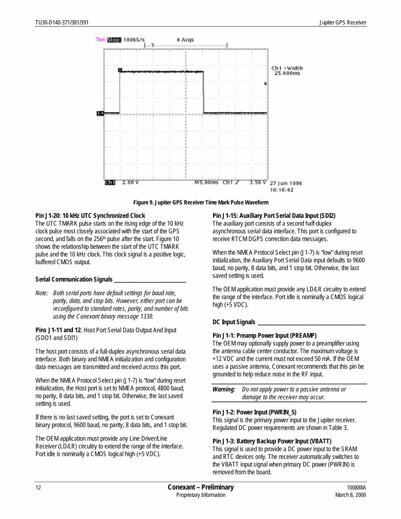
The TMARK pulse waveform is shown in Figure 9. This signal isa positive logic, buffered CMOS level output pulse thattransitions from a logic “low” condition to a logic “high” at a 1 Hzrate. The TMARK output pulse rise time is typically less than2 ns and the pulse duration is typically 25.6 ms.
Table 5. Jupiter Receiver Serial Port Configuration Truth Table
NMEA ProtocolSelect(Pin 7)
ROM DefaultSelect(Pin 8)
Result
0 0 NMEA message format; host port communication settings = 4800 bps, no parity, 8 data bits, 1stop bit. The receiver operates from default initialization values stored in ROM and outputs thedefault NMEA message set from ROM.
0 1 NMEA message format; host port communication settings = 4800 bps, no parity, 8 data bits, 1stop bit. The receiver selects the default NMEA output message set and uses initializationvalues from the data stored in SRAM or EEPROM (Note 1).
1 0 Binary message format; host port communication settings = 9600 bps, no parity, 8 data bits, 1stop bit. The receiver operates from default initialization values stored in ROM.
1 1 Data stored in SRAM or EEPROM determines message format, host port communicationsettings, and default message set (Note 1).
Note 1: For further information, refer to the description of the ROM Default Select pin (J1-8) below.

Jupiter GPS Receiver TU30-D140-371/381/391
100888A Conexant – Preliminary 11March 8, 2000 Proprietary Information
Table 6. Jupiter GPS Receiver Digital Signal Requirements
Symbol Parameter Limits (Note 1) Units
PWRIN_5 Primary Power Input to the Jupiter (+5 VDC) 4.75 to 5.25 volts
VIH (min) Minimum High-Level Input Voltage 0.7 x PWRIN volts
VIH (max) Maximum High-Level Input Voltage PWRIN volts
VIL (min) Minimum Low-Level Input Voltage –0.3 volts
VIL (max) Maximum Low-Level Input Voltage 0.3 x PWRIN volts
VOH (min) Minimum High-Level Output Voltage 0.8 x PWRIN volts
VOH (max) Maximum High-Level Output Voltage PWRIN volts
VOL (min) Minimum Low-Level Output Voltage 0 volts
VOL (max) Maximum Low-Level Output Voltage 0.2 x PWRIN volts
tr, tf Input Rise and Fall Time 50 nanoseconds
C out Maximum Output Load Capacitance 25 picofarads
Note 1: PWRIN refers to a +5 VDC power input (PWRIN_5).
1 PPS
t t+1 t+2
msg 1108 t msg 1108 t+1 msg 1108 t+2Binary message1108 data (*)
(*) Binary message data, 9600 bps, receiver reporting valid navigation solution C320
Figure 8. UTC Time Mark Pulse Output Message/UTC TMARK Pulse Relationship
TU30-D140-371/381/391 Jupiter GPS Receiver
12 Conexant – Preliminary 100888AProprietary Information March 8, 2000
Figure 9. Jupiter GPS Receiver Time Mark Pulse Waveform
Pin J1-20: 10 kHz UTC Synchronized ClockThe UTC TMARK pulse starts on the rising edge of the 10 kHzclock pulse most closely associated with the start of the GPSsecond, and falls on the 256th pulse after the start. Figure 10shows the relationship between the start of the UTC TMARKpulse and the 10 kHz clock. This clock signal is a positive logic,buffered CMOS output.
Serial Communication Signals ________________________
Note: Both serial ports have default settings for baud rate,parity, data, and stop bits. However, either port can bereconfigured to standard rates, parity, and number of bitsusing the Conexant binary message 1330.
Pins J1-11 and 12: Host Port Serial Data Output And Input(SDO1 and SDI1)
The host port consists of a full-duplex asynchronous serial datainterface. Both binary and NMEA initialization and configurationdata messages are transmitted and received across this port.
When the NMEA Protocol Select pin (J1-7) is “low” during resetinitialization, the Host port is set to NMEA protocol, 4800 baud,no parity, 8 data bits, and 1 stop bit. Otherwise, the last savedsetting is used.
If there is no last saved setting, the port is set to Conexantbinary protocol, 9600 baud, no parity, 8 data bits, and 1 stop bit.
The OEM application must provide any Line Driver/LineReceiver (LD/LR) circuitry to extend the range of the interface.Port idle is nominally a CMOS logical high (+5 VDC).
Pin J1-15: Auxiliary Port Serial Data Input (SDI2)The auxiliary port consists of a second half-duplexasynchronous serial data interface. This port is configured toreceive RTCM DGPS correction data messages.
When the NMEA Protocol Select pin (J1-7) is “low” during resetinitialization, the Auxiliary Port Serial Data input defaults to 9600baud, no parity, 8 data bits, and 1 stop bit. Otherwise, the lastsaved setting is used.
The OEM application must provide any LD/LR circuitry to extendthe range of the interface. Port idle is nominally a CMOS logicalhigh (+5 VDC).
DC Input Signals ____________________________________
Pin J1-1: Preamp Power Input (PREAMP)The OEM may optionally supply power to a preamplifier usingthe antenna cable center conductor. The maximum voltage is+12 VDC and the current must not exceed 50 mA. If the OEMuses a passive antenna, Conexant recommends that this pin begrounded to help reduce noise in the RF input.
Warning: Do not apply power to a passive antenna ordamage to the receiver may occur.
Pin J1-2: Power Input (PWRIN_5)This signal is the primary power input to the Jupiter receiver.Regulated DC power requirements are shown in Table 3.
Pin J1-3: Battery Backup Power Input (VBATT)This signal is used to provide a DC power input to the SRAMand RTC devices only. The receiver automatically switches tothe VBATT input signal when primary DC power (PWRIN) isremoved from the board.

Jupiter GPS Receiver TU30-D140-371/381/391
100888A Conexant – Preliminary 13March 8, 2000 Proprietary Information
C305
Figure 10. 10 kHz Clock Waveform/UTC TMARK Pulse Relationship
This feature is intended to provide the receiver with a “warmstart” capability by maintaining an accurate time source andusing position and satellite data stored in SRAM after primeinput power (PWRIN) has been removed from the receiver.
In the standby mode, the receiver draws only a few microamps(see Table 3). This current level is appropriate for battery use.However, the battery voltage must be equal to, or less than, thenormal PWRIN voltage so that during periods when the receiveroperates on normal power, the battery is not required to supplyfull SRAM power. Since the SRAM chips do not require morethan 3V to maintain their memory, it is acceptable to supplythem with a 3V battery even when the rest of the system is 5V.
Pin J1-4: ReservedThis signal is reserved and no electrical connections should bemade to the OEM application.
Pins J1-10, 13, 16, 17, and 18: Ground (GND)DC grounds for the board. All grounds are tied together throughthe receiver’s printed wiring board (PWB) ground plane andshould all be grounded externally to the receiver.
Software Interface
The host serial I/O port of the Jupiter’s serial data interfacesupports full duplex communication between the receiver and
the OEM application. Data messages can be in the Conexantbinary format or NMEA-0183 format. The receiver also containsan auxiliary port dedicated to direct processing of the RTCM SC-104 messages for DGPS corrections.
Binary Data Messages. All of the output and input binarymessages for the Jupiter receiver are listed in Table 7, alongwith their corresponding message IDs. A complete description ofeach binary message is contained in the Conexant document,Zodiac GPS Receiver Family Designer’s Guide.
NMEA Data Messages. The Jupiter LP supports NMEA v2.01data messages. All of the output and input NMEA messages forthe Jupiter receiver are listed in Table 8 along with theircorresponding message IDs. A complete description of eachNMEA message is contained in the Conexant document, ZodiacGPS Receiver Family Designer’s Guide.
RTCM SC-104 Data Messages. Table 9 lists those messagesdefined in the RTCM SC-104 standard that are used by theJupiter receiver to form a DGPS position solution (not all DGPSmessages are necessary for DGPS operation).

TU30-D140-371/381/391 Jupiter GPS Receiver
14 Conexant – Preliminary 100888AProprietary Information March 8, 2000
Table 7. Jupiter Receiver Binary Data Messages
Output Message Name Message ID Input Message Name Message IDGeodetic Position Status Output (*) 1000 Geodetic Position and Velocity Initialization 1200
Channel Summary (*) 1002 User-Defined Datum Definition 1210
Visible Satellites (*) 1003 Map Datum Select 1211
Differential GPS Status 1005 Satellite Elevation Mask Control 1212
Channel Measurement 1007 Satellite Candidate Select 1213
ECEF Position Output 1009 Differential GPS Control 1214
Receiver ID (**) 1011 Cold Start Control 1216
User-Settings Output 1012 Solution Validity Criteria 1217
Raw Almanac Output 1040 User-Entered Altitude Input 1219
Raw Ephemeris Output 1041 Application Platform Control 1220
Raw Ionospheric and UTC Corrections Output 1042 Nav Configuration 1221
Built-In Test Results 1100 Raw Almanac Input 1240
UTC Time Mark Pulse Output (*) 1108 Raw Ephemeris Input 1241
Frequency Standard Parameters In Use 1110 Raw Ionospheric and UTC Corrections Input 1242
Serial Port Communication Parameters In Use 1130 Perform Built-In Test Command 1300
EEPROM Update 1135 Restart Command 1303
EEPROM Status 1136 Frequency Standard Input Parameters 1310
Frequency Standard Table Output Data 1160 Serial Port Communication Parameters 1330
Error/Status 1190 Message Protocol Control 1331
Factory Calibration Input 1350
Raw DGPS RTCM SC-104 Data 1351
Frequency Standard Table Input Data 1360
(*) Enabled by default at power-up.(**) Output by default once at power-up or reset.

Jupiter GPS Receiver TU30-D140-371/381/391
100888A Conexant – Preliminary 15March 8, 2000 Proprietary Information
Table 8. Jupiter Receiver NMEA v2.01 Data Messages
Output Message Name Message ID Input Message Name Message IDConexant Proprietary Built-In Test (BIT) Results BIT Conexant Proprietary Built-In Test (BIT) Command IBIT
Conexant Proprietary Error/Status ERR Conexant Proprietary Log Control Message ILOG
GPS Fix Data (*) GGA Conexant Proprietary Receiver Initialization INIT
GPS DOP and Active Satellites (*) GSA Conexant Proprietary Protocol Message IPRO
GPS Satellites in View (*) GSV Standard Query Message Q
Conexant Proprietary Receiver ID (**) RID
Recommended Minimum Specific GPS Data (*) RMC
Track Made Good and Ground Speed VTG
Conexant Proprietary Zodiac Channel Status (*) ZCH
(*) Enabled by default at power-up.(**) Output by default once at power-up or reset.
Table 9. Jupiter Receiver RTCM SC-104 Data Messages
Message ID Title Used For DGPS Corrections?1 Differential GPS Corrections Yes2 Delta DGPS Corrections Yes3 Reference Station Parameters No6 Null Frame No9 Partial Satellite Set Differential Corrections Yes

TU30-D140-371/381/391 Jupiter GPS Receiver
16 Conexant – Preliminary 100888AProprietary Information March 8, 2000
Ordering Information
Model Name Manufacturing PartNumber
Product Revision
Jupiterw/straight OSXw/right angle OSXw/right angle SMB
TU30-D140-371-381-391
© 2000, Conexant Systems, Inc. All Rights Reserved.
Information in this document is provided in connection with Conexant Systems, Inc. ("Conexant") products. These materials are provided by Conexant as a service to itscustomers and may be used for informational purposes only. Conexant assumes no responsibility for errors or omissions in these materials. Conexant may make changes tospecifications and product descriptions at any time, without notice. Conexant makes no commitment to update the information and shall have no responsibility whatsoeverfor conflicts or incompatibilities arising from future changes to its specifications and product descriptions.
No license, express or implied, by estoppel or otherwise, to any intellectual property rights is granted by this document. Except as provided in Conexant’s Terms andConditions of Sale for such products, Conexant assumes no liability whatsoever.
THESE MATERIALS ARE PROVIDED "AS IS" WITHOUT WARRANTY OF ANY KIND, EITHER EXPRESSED OR IMPLIED, RELATING TO SALE AND/OR USE OFCONEXANT PRODUCTS INCLUDING LIABILITY OR WARRANTIES RELATING TO FITNESS FOR A PARTICULAR PURPOSE, CONSEQUENTIAL OR INCIDENTALDAMAGES, MERCHANTABILITY, OR INFRINGEMENT OF ANY PATENT, COPYRIGHT OR OTHER INTELLECTUAL PROPERTY RIGHT. CONEXANT FURTHERDOES NOT WARRANT THE ACCURACY OR COMPLETENESS OF THE INFORMATION, TEXT, GRAPHICS OR OTHER ITEMS CONTAINED WITHIN THESEMATERIALS. CONEXANT SHALL NOT BE LIABLE FOR ANY SPECIAL, INDIRECT, INCIDENTAL, OR CONSEQUENTIAL DAMAGES, INCLUDING WITHOUTLIMITATION, LOST REVENUES OR LOST PROFITS, WHICH MAY RESULT FROM THE USE OF THESE MATERIALS.
Conexant products are not intended for use in medical, lifesaving or life sustaining applications. Conexant customers using or selling Conexant products for use in suchapplications do so at their own risk and agree to fully indemnify Conexant for any damages resulting from such improper use or sale.
The following are trademarks of Conexant Systems, Inc.: Conexant™, the Conexant C™ symbol, and “What’s Next in Communications Technologies”™. Product names orservices listed in this publication are for identification purposes only, and may be trademarks of third parties. Third-party brands and names are the property of theirrespective owners.
Additional information, posted at www.conexant.com, is incorporated by reference.
Reader Response: Conexant strives to produce quality documentation and welcomes your feedback. Please send comments and suggestions [email protected]. For technical questions, contact your local Conexant sales office or field applications engineer.

Further Information:[email protected] (North America)33-14-906-3980 (International)
Web Sitewww.conexant.com
World HeadquartersConexant Systems, Inc.4311 Jamboree Road,P.O. Box CNewport Beach, CA 92658-8902Phone: (949) 483-4600Fax: (949) 483-6375
U.S. Florida/South AmericaPhone: (727) 799-8406Fax: (727) 799-8306
U.S. Los AngelesPhone: (805) 376-0559Fax: (805) 376-8180
U.S. Mid-AtlanticPhone: (215) 244-6784Fax: (215) 244-9292
U.S. North CentralPhone: (630) 773-3454Fax: (630) 773-3907
U.S. NortheastPhone: (978) 367-3200Fax: (978) 256-6868
U.S. Northwest/Pacific WestPhone: (408) 249-9696Fax: (408) 249-7113
U.S. South CentralPhone: (972) 733-0723Fax: (972) 407-0639
U.S. SoutheastPhone: (919) 858-9110Fax: (919) 858-8669
U.S. SouthwestPhone: (949) 483-9119Fax: (949) 483-9090
APAC HeadquartersConexant Systems Singapore,Pte. Ltd.1 Kim Seng PromenadeGreat World City#09-01 East TowerSingapore 237994Phone: (65) 737 7355Fax: (65) 737 9077
AustraliaPhone: (61 2) 9869 4088Fax: (61 2) 9869 4077
ChinaPhone: (86 2) 6361 2515Fax: (86 2) 6361 2516
Hong KongPhone: (852) 2 827 0181Fax: (852) 2 827 6488
IndiaPhone: (91 11) 692 4780Fax: (91 11) 692 4712
Korea - Seoul OfficePhone: (82 2) 565 2880Fax: (82 2) 565 1440
Korea - Taegu OfficePhone: (82 53) 745 2880Fax: (82 53) 745 1440
Europe HeadquartersConexant Systems FranceLes Taissounieres B11681 Route des DolinesBP 28306905 Sophia Antipolis CedexFrancePhone: (33 1) 41 44 36 50Fax: (33 1) 93 00 33 03
Europe CentralPhone: (49 89) 829 1320Fax: (49 89) 834 2734
Europe MediterraneanPhone: (39 02) 9317 9911Fax (39 02) 9317 9913
Europe NorthPhone: (44 1344) 486 444Fax: (44 1344) 486 555
Europe SouthPhone: (33 1) 41 44 36 50Fax: (33 1) 41 44 36 90
Middle East HeadquartersConexant Systems Commercial(Israel) Ltd.P.O. Box 12660Herzlia 46733IsraelPhone: (972 9) 952 4064Fax: (972 9) 951 3924
Japan HeadquartersConexant Systems Japan Co., Ltd.Shimomoto Building1-46-3 Hatsudai,Shibuya-kuTokyo, 151-0061JapanPhone: (81 3) 5371 1567Fax: (81 3) 5371 1501
Taiwan HeadquartersConexant Systems, Taiwan Co., Ltd.Room 2808International Trade Building333 Keelung Road, Section 1Taipei 110Taiwan, ROCPhone: (886 2) 2720 0282Fax: (886 2) 2757 6760