tsubaki power cylinder t-seriestsubaki.de/power cylinder t-series 2014.pdf · power cylinder t...
TRANSCRIPT

Linear Actuator
MO
TO
R A
DA
PT
ER
TY
PE W
ITH
MO
TO
R T
YP
E
POWER CYLINDERT-Series
TSUBAKI

TSUBAKI E&M Power Cylinders were born over 40 years ago, and have been used across a
variety of industries by a wide range of customers.
By taking advantage of our accumulated experience, we have continued to develop new
products as well as upgrade technologies, and proactively address environmental issues to
create our present series.
We will continue to create products which are customer-friendly, taking the environment into
consideration.
1

2

Compared to hydraulic or pneumatic cylinders,
our Power Cylinder is more economical because it needs less electricity.
Power Cylinder is “ecologically-
Power Cylinder
Pneumatic Cylinder Hydraulic Cylinder
Power
Work
Work
Power
Power
Work
Power Cylinder is simple structure, so the
conversion efficiency from power supply to
work is very high!
・Clean operationClean operation is possible because there is oil leak.
・Easy installationUnlike hydraulic cylinders, operation at a high place and under adverse
environment is easier, because Power Cylinder does not require unit installation.
・Operable only by electrical wiringAll you need for operation is electrical wiring.
System Structure
3

friendly”
All area
User’s voice
■ We wanted energy saving products for future power shortage.
Oil/air leak maintenance frequency is reduced.
Easy speed control.
No more labor shortage for maintenance of oil system.
Compared to Pneumatic Cylinder & Hydraulic Cylinder…
Shipbuilding, Hydraulic power,Sewer processing
■ It can avoid water & sea pollution by oil leak.
Medical
■ It is clean because of no oil leak.
Steel plant
■ The number of remote controls (long distance line) and
pipe fittings is reduced.
■ Oil leak is a fire hazard at high temperature area.
Metalworking machine
■ The positioning accuracy is better than Pneumatic Cylinder.
■ Several Power Cylinders can be synchronized.
The comparison result by Shinko Research Co.,
■ CO2 emission (kg-CO2/year)
■ electric JPY22/kWH ■ 50cylinders usage
The data omits distribution, disposal, recycle “as equivalent” from LCA for comparison.
Reference : MiLCA ver1.0 by JEMAI, and other catalogs
Electricity cost/ Plant
CO2 emission
<relation condition>■ thrust 3000N ■ speed 200mm/s ■ stroke 500mm ■ 1RT/min x 12hrs/day x 250days/year
■ included each drive (servo motor, hydraulic unit)
Electricity usage
0
200
400
600
800Upper : emissions by running
Lower : emissions by running
Power Cylinder Power CylinderPneumatic Cylinder
584
33
Hydraulic Cylinder
493
13
Pneumatic Cylinder Hydraulic Cylinder
9142
0
500
1000
1500
2000
19871676
310
■ Comparison of electricity per 1set (kWh/year) Electricitycomparison
The case of Power Cylinder : 1
Pneumatic Cylinder : 6.4Hydraulic Cylinder : 5.4
Increase electricity cost.
CO2 comparison
The case of Power Cylinder : 1
Pneumatic Cylinder : 4.6Hydraulic Cylinder : 3.8
Increase CO2 emission.
vs. Pneumatic Cylinder ▲1.85miilion yen/year
vs. Hydraulic Cylinder ▲1.5million yen/year
84% reduction
82% reduction
4

Power Cylinder T seriesMotor Adapter type
APPLICATION EXAMPLES
HOPPER GATE DIVERTER GATEHOPPER GATE
Customer can mount your desired motor on side. see page 11
We can also provide the unit equipped three phase motor with brake. see page 13
Internal Position sensor; Limit switch type: K2, K4
Available at your choice for signaling the position of the stroke.
see page 34
Positionmeter (Analog): P
Rotary Encoder (Digital): R
Available at your choice for remote control operation. see page 34
High Performance linear actuators offering efficient,Clean and Quite drive... Environmental consciousness.
Note) Mounting cannot be carried out with clevis fitting.Mount this unit with trunnion fitting.
Position detecting unit
5

SHIP LOADER GATE SWITCHING
External Limit switches: L
Available at your choice for adjusting the stroke
of the acuator.
Bellows: J
To be used in dusty areas
when needed.
Press Loaded Stopping Device;
(LPTC type)
For safety and thrust sensing.
A combination of disk springs and limit switches is used
to provide thrust sensing and press loaded stopping.
SLIDE GATE
-Tough -Extremely Durable -Will exceed your expectations
6

Power CylinderExamples of use
Various types of opening and closing can be performed by changing the linear motion of power cylinders into turning force through link mechanisms or by using the linear motion as it is. The G series (GC type) and T series (TC type) that can press at the end are suitable. Those with a position detecting unit are used to indicate the degree of opening.
● Opening and closing of hopper gates● Opening and closing of switching dampers● Opening and closing of the lids of drying furnaces, incinerators, various kilns, etc.
Opening and closing
Conveyed objects can be turned over and transferred by the l inear motion of power cyl inders and simple supporting arrangements. Smooth operation can be performed with little backlash.
● Turnover devices for steel materials and packaged goods
● Lateral turning of wire bobbins● Turnover of furnaces
Turnover
Conveyed objects can be stopped or changed in direction mainly through the link mechanisms in addition to the linear motion of power cylinders. Also, they can be stopped directly by power cylinders.
● Directional adjustments of the flows of conveyed objects on belt conveyors
● Stopper for conveyed objects on roller conveyors● Stopper for materials in material cutting machines
Stopper
7

Model No. designation / Standard model list
Structure
Motor Adapter type
Classification of usage for LPTB and LPTC types
Selection
Dimensions Table
Position detecting unit
Wire connection
Installation / Maintenance
Warning
Inquiry Form
Table of Contens9
10
11
15
16
19
34
39
43
44
45
Pow
er C
ylin
der
8

1) The rated thrust is limited for the stroke marked with an*.2) The speeds indicate a value at the motor synchronized rotating speed.
Note) The numerical value in parentheses on rated thrust is for the long stroke type.
N
LPTBLPTC
LPTBLPTC
LPTBLPTC
LPTBLPTC
LPTBLPTC
LPTBLPTC
LPTBLPTC
LPTBLPTC
LPTBLPTC
LPTBLPTC
250
500
1000
2000
4000
6000
8000
12000
16000
32000
SLMHSLMHSLMHSLMHSLMHSLMHSLMH
LMH
LMH
LMH
12.5/1525/3050/60100/12012.5/1525/3050/60100/12012.5/1525/3050/60100/12012.5/1525/3050/6075/909/1125/3035/4260/726.3/7.617.5/2125/3042/5010/1220/2430/3643/52
10/1218/2230/36
14.5/17.520/2431/37
10/1215/1820/24
2.01.02.04.02.01.02.03.92.01.02.04.02.01.02.03.01.41.01.42.41.00.71.01.71.20.81.21.7
1.22.21.2
2.93.23.7
0.40.60.8
0.10.10.20.40.10.20.40.750.20.40.751.50.40.751.52.20.751.52.23.70.751.52.23.71.52.23.75.5
2.23.75.5
3.75.57.5
5.57.511
2.60
5.20
13.8
34.7
83.2
124
222
333
666
1330
0.27
0.53
1.41
3.54
8.49
12.7
22.6
34.0
67.9
136
200, 300, 400500, 600
200, 300, 400500, 600, 800
200, 300, 400500, 600, 800
※1000
200, 300, 400500, 600, 800
※1000 ※1200
※1500
200, 300, 400500, 600, 8001000, 1200
50010001500
50010001500
500100015002000500100015002000500100015002000
250
500
1000(800)
2000(1600)(1250)
4000(3400)
6000
8000
12000
16000
32000
2.45k
4.90k
9.80k(7.84k)
19.6k(15.6k)(12.2k)
39.2k(33.3k)
58.8k
78.4k
117k
156k
313k
{kNf } N・m{kNf・m }
Nominal speed50/60Hzmm/s
Nominal strokemm
Motor outputkW
Rod rotating forceBrake specifications
RatedthrustPower cylinder
model
Rod movement per one turn of manual
shaft mm
(Note)With motor type● ●
LPTB:Wet slip clutch typeLPTC:Thrust detection mechanism type
:With two stroke adjusting external LSs:With three stroke adjusting external LSs:Position detecting internal LS:Potentiometer:Rotary encoder:With clevis fitting:Ⅰ-shaped end fitting (no symbol for standard):With bellows:Motor terminal box and external LS mirror image specifications
250 :2.45kN{ 250kNf }500 :4.90kN{ 500kNf }1000 :9.80kN{ 1000kNf }2000 :19.6kN{ 2000kNf }4000 :39.2kN{ 4000kNf }6000 :58.8kN{ 6000kNf }8000 :78.4kN{ 8000kNf }12000:117kN{ 12000kgf }16000:156kN{ 16000kgf }32000:313kN{ 32000kgf }
:S, L, M, H
2:200mm 3:300mm 5:500mm10:1000mm
*2
LL3K2,K4PRC JF
Ⅰ*3
*4
*5
LP TB 1000 L 4 A LPCⅠJF
*The above values are examples of indication.
With motor type; Refere to page 11
*2 When four or more clevises are installed, indicate this to us separately.
* The clevis tting cannot be combined with K2, K4, P or R.*4 For PT6000 and above, the I-type end tting is standard (no
symbol).*5 The stroke is not changed.
9

Pow
er C
ylin
der
With wet slip clutch protection device (Basic type)
With thrust detecting mechanism (Basic type)
* The structure slightly varies depending on the model.
Brake motor
Manual handle shaft
Outer cylinder Rod
End fittingBall screwBracketWet slip clutchGear
Brake motor
Manual handle shaft
Outer cylinder Rod
End fittingBall screwBracketGear
Thrust detecting spring unit
LS part
Striker
Thrust detecting limit switch
1) 400/440 , different voltage speci cations other than the above voltages are also available.2) For motor current value and brake current value, refer to page 41.
-15℃~40℃
TSUBAKI olive gray (Munsell 5GY6/0.5 or approximate color)
1) Cylinders with bellows are recommended in an excessively dusty location.
2) Special painting is available for locations exposed to sea breezes and salt. Consult us.
) All models are totally enclosed structures so that they can be used normally
outdoors, however, under adverse conditions exposed to constant water and steam
etc., and snow accumulation, although they are an outdoors type, an appropriate
cover is required. When using at 40℃ or higher, always protect with a heat insulating
cover, etc. Never use in a ammable atmosphere, otherwise it may cause an
explosion and re. In addition, avoid using it in a location where vibration or shock
exceeding 1G is applied.
4) For use in a misty atmosphere, contact us.
Totally enclosed self cooling type with brakeRefer to Standard model dimensions list
4 poles3φ 200V/200V/220V50Hz/60Hz/60HzE (B for 1.5kW or less)
S2 30min.Totally enclosed outdoor type (IP55)
Environ-ment
ModelAmbient temperature
Relativehumidity
Impact resistancevalue
Installationaltitude Atmosphere
85%or less
(no dew condensation)
1Gor less
Normallyoutdoors
1000mor lower abovesea level
10

・Power Cylinder Motor Adapter types are cylinder on which you can easily mount a motor with a brake, such as your regional standard motor, global standard motor (e.g. UL, CE, CCC), or pressure-resistant explosion-proof motor.
・Available for IEC standard flange motor.
・Motor Adaptor type cylinder which is for a NEMA motor, a servo motor, and a special shaft-end motor is also available. Please contact us for detail.
・Standard motor of your country
・Explosion-proof motors
・Other special motors
LPTB500L6AL -TK
Motor Adapter type
This cylinder can be installed to motors
conforming to the "IEC" standard.
IEC
Explosion-proof
11

LPTBLPTC
250
LPTBLPTC
500
LPTBLPTC
1000
LPTBLPTC
2000
LPTBLPTC
4000
LPTBLPTC
6000
LPTBLPTC
8000
LPTBLPTC
12000
LPTBLPTC
16000
LPTBLPTC
32000
Speed
SLMHSLMHSLMHSLMHSLMHSLMHSLMHLMHLMH
L,M,H
0.10.10.20.40.10.20.40.750.20.40.751.50.40.751.5
0.751.52.23.70.751.52.23.71.52.23.75.52.23.75.53.75.57.5
63636371M636371M80M6371M80M90L71M80M90L
Please contact us80M90L100L112M80M90L100L112M90L100L112M132S100L112M132S112M132S132M
Please contact us
807272728072729280729292857272
907211611690751161161379696121145145121145170170
Motor output4P-(kW)
Motorsize
DimensionALModel
130130130130130130130165130130165165130165165
165165215215165165215215165215215265215215265215265265
FF130FF130FF130FF130FF130FF130FF130FF165FF130FF130FF165FF165FF130FF165FF165
FF165FF165FF215FF215FF165FF165FF215FF215FF165FF215FF215FF265FF215FF215FF265FF215FF215FF215
110 j6110 j6110 j6110 j6110 j6110 j6110 j6130 j6110 j6110 j6130 j6130 j6110 j6130 j6130 j6
130 j6130 j6180 j6180 j6130 j6130 j6180 j6180 j6130 j6180 j6180 j6230 j6180 j6180 j6230 j6180 j6230 j6230 j6
160160160160160160160200160160200200160200200
200200250250200200250250200250250300250250300250300300
3.53.53.53.53.53.53.53.53.53.53.53.53.53.53.5
3.53.5443.53.5443.5444444444
232323302323304023304050304050
405060604050606050606080606080608080
101010101010101210101212101212
Please contact us121214.514.5121214.514.51214.514.514.514.514.514.514.514.514.5
Please contact us
LA LB LC LE LR LZ232323302323304023304050304050
405060604050606050606080606080608080
11 h611 h611 h614 j611 h611 h614 j619 j611 h614 j619 j624 j614 j619 j624 j6
19 j624 j628 j628 j619 j624 j628 j628 j624 j628 j628 j638 k628 j628 j638 k628 j638 k638 k6
444544564568568
6888688888810881081010
444544564567567
677767777775775755
2.52.52.532.52.533.52.533.5433.54
3.54443.54444448448488
(mm)
Q S W T U
IEC flange dimensionIECflange
W
AL LR
LE
Q
φS
4-φLZ
φLCφLB
φLA
T
U
In order to exert the same capacity as those of the Power Cylinder T series.The motor start torque should be "200%" of the rated torque or moreand the brake torque should be "150%" of the rated torque or more.
Pow
er C
ylin
der
12

■ ■・
・・・
・・
■ ■
■
■
11
40℃ 60℃
80℃
Model No. designation
Special Brake motor
LP T C 4000 L 10 V T1 LJ - TK
With Motor type
Power cylinder
Series name Protective device
Thrust Option
Motor specification symbol
Voltage symbol
Stroke
Speed
No symbol:200V class200/200/220V 50/60/60Hz
V:400V class400/400/440V 50/60/60Hz
22
13

■
■
■
■
■■
■
・・・
・・・・
■・・
・・
■・・・
・
44
33
55
■
Pow
er C
ylin
der
14

Both types of the power cylinders have the same basic functions (thrust, speed, stroke), however, each has its feature as regards the
mechanism. Read the following to select the optimum type.
Note) When the power cylinder is used for press (pull) contact stopping, external wiring is recommended for the wire connection of the brake.
Note) When the power cylinder is used exceeding the values on the above table, it is recommended to stop with the stroke adjusting LS.
Note) When the power cylinder is used with press (pull) stop, strength of the mating equipment shall be 250% or more of the rated thrust.
● ●
Type
Reference total stop times(×104times)
LPTC250~LPTC4000 LPTC6000~LPTC32000
S,L
30
M
10
H
5
S,L
10
M
3
H
1 ②
For the TC type, a spring mechanism is built in the operating part,
therefore, when a large load is applied from the load side, the spring
de ects and the rod moves by the de ection.
When the load is eliminated, the rod returns to the original position.
①For the TC type, a spring mechanism is built in the operating part. The
spring slightly de ects at press (pull) and stop, or when overload occurs,
the signal amount deviates by the de ection. For the TB type, even if the
safety device is tripped, signal amount does not deviate. However, the
TC type can be used at normal stroke operation.Speed
When using the power cylinder at a frequency of ten or more times a day, refer to the total stop times for every model in the following table.
●
● ①②③
When an overload is impulsively applied, the incorporated spring absorbs the impact load.
The screw shaft end of the reduction part incorporates a slip clutch which operates stably in grease as a safety device.
Adoption of special lining exerts a protective function even at the time of overload or stroke overextension.
* When overload is electrically detected, use in combination with our shock relay is recommended.
This is a thrust detecting mechanism which combines two types of pre-loaded disc springs whose spring constants are different from each other and limit
switches. The combined effect of these disc springs also allows for press and stop of the high speed type. (There is only one type for the 6000 type and larger.)
Striker
・When the cylinder is overloaded during retracting・ When the cylinder stops within the XA dimension at
the time of retracting・When a press ing force is at tempted to be
maintained even after stop
・When the cylinder is overloaded while extending・When the cylinder stops within the XA dimension at
the time of extending・When a press ing force is a t tempted to be
maintained even after stop
Mass of carriage: OCoefficient of friction:μCarriage traveling resistance: =μ ≦Rated thrust
For both of the TB type and TC type, the thrust for the safety device has been set to approximately 150% to 200% of the rated thrust. The safety device does not work at the start for opening/closing of the damper or the hopper gate, normal reverse, inclination and elevation, however, when a load inertia is large due to horizontal movement of carriage, the safety device may work to impair smooth operation at the start. For the allowable mass of each model, see Table 4 on page 18.
15

Pow
er C
ylin
der
Note) The above frequencies of operation are values determined by heat generation of the motor. They are not values taking life of the cylinder body into consideration.
LPTB・LPTC
32000H
2
LPTB・LPTC
16000H32000M
3
LPTB・LPTC
18000H12000H16000M32000L
3
LPTB・LPTC14000H16000H18000M12000M16000L4
LPTB・LPTC12000H14000M16000M18000L12000L4
LPTB・LPTC1000H2000M4000L6000L8000S4
LPTB・LPTC1500H1000M2000L4000S6000S4
LPTB・LPTC
1250H1500M1000L2000S
5
LPTB・LPTC
1250M1500L1000S
5
LPTB・LPTC
250S250L500S
5
25%ED
Annual traveling distance km = Actual stroke m x Frequency of use/day x number of operating days x 10-3
1. Machine to be used and application2. Thrust or load N { ㎏f }3. Stroke mm4. Speed mm/s5. Frequency of operation, cycles/min.
6. Hours of operation and annual number of operating days 7. Type of load of machine used8. Environment of use9. Power voltage, frequency
2. Obtain the operation factor from the characteristics of load and the machine used, referring to Table 1.
Determine the type (TB or TC) according to the use environment and method of operation.
1. Obtain annual traveling distance from the stroke, frequency of operation and hours of operation.
1. Use the power cylinder at a frequency of operation below the allowable frequency of operation (Table 2).
2. Check the load time ratio.3. Positioning accuracy varies depending on the stopping method. Refer to
the stopping method (page 17).
3. Multiply thrust or load by operation factor to obtain a corrected thrust.4. Determine the frame No. from the “Expected Traveling Distance” shown
below on this page according to the corrected thrust and annual traveling distance, and select an applicable model No. from the standard model list (page 9) based on the stroke, speed, power supply voltage and frequency.
Example of machine used Operationfactor
Damper, opening/closing of valve, conveyor changeover device
Characteristics of load
Smooth operation without impactSmall inertia
Opening/closing of hopper gate, various transfer equipment, various lifter elevation
Operation with light impactIntermediate inertia
Heavy object conveyance by carriage, buffer for belt conveyor, inversion opening/closing device for large lid
Operation with large impactand vibrationLarge inertia
Note) The above operation factor table shows general guidelines. Therefore, make a determination in consideration of operating conditions.
Type
%
Allowable frequency of operation for the power cylinder T series is within a range which satis es the number of starting times and load time ratio in the above table. The load time ratio is expressed by the following equation.
Load time ratio (%ED) = ×100%Operation time of one cycle
(Operation time of one cycle + dwell time)
Use the number of operation times of the brake and the traveling distance of the cylinder (nut) as a guide for product life of the power cylinder T series to select the cylinder (nut).
Expected life 2 million times
The life of a ball screw is determined by aking of the rolling surface caused by its fatigue. Check the rough life with this chart of expected traveling distance. However, in the case of great impact or in the case where lubrication or maintenance is not performed properly, the expected traveling distance becomes substantially short.
The chart on the right-hand side is based on L10 life. L10 life expresses in traveling distance a life that can be reached by 90% or more of all ball screws. If you select a power cylinder based on the life, select model No. from this chart.If the load greatly uctuates in the middle of stroke, calculate the equivalent load (PM) by the following equation.
16

* When selecting the H speed, refer to the cautions for selecting on page 44.* Select a power cylinder of a suf cient thrust, allowing for a safety rate so that the loads used (static and dynamic) do not exceed the rated thrust.
60030
10×60×100=6.7%<25%
×2
Determination of type With press and stop, internal stop → Select TC type
Determination of model No. :1.3
:12.7kN{1300kgf }×1.3=16.5kN{1680kgf }
: LPTC 2000L6 K2 J
Characteristics check
Life check
● :2 times/10min<4 times/min
● :
:2 times/1 reciprocation, durable years 5 years (250 days/year) 2×6×10×250×5=15 x 104 times<30 x 104 times
Opening degree adjustment type damper open/close(Stop at middle two points, press and stop at extend limit and retract limit)
:0.6×2×6 times/hour×10 hours/day×250 days/year×10-3=18km
:18km×5 years=90km
:PM= 16.5+16.5×23
=16.5kN{1680kgf }This calculated value satis es the expected traveling life of LPTC 2000 according to the load-life diagram on page 16.
:
:12.7kN{1300kgf}
:600mm
:600mm/s for approximately 20 seconds
:One reciprocation/10 minutes (6 reciprocations/hour)
:10 hours/day, 250 days operation/year, durable years approximately 5 years
:Operation with light impact, loaded when extend and retract
:Outdoor installation, much dust, temperature 0℃~35℃
: 220V 60Hz
Stop at two middle points With bellows (much dust)
LPTBLPTC 250
SLMH
LPTBLPTC 500
SLMH
LPTBLPTC 1000
SLMH
LPTBLPTC 2000
SLMH
LPTBLPTC 4000
SLMH
LPTBLPTC 6000
SLMH
LPTBLPTC 8000
SLMH
LPTBLPTC12000
LMH
LPTBLPTC16000
LMH
LPTBLPTC32000
LMH
2.24.36.913.72.13.66.512.71.73.26.315.61.73.27.713.31.23.86.410.90.62.74.57.61.93.65.6-2.13.5-2.8-----
±0.4±0.8±1.4±2.7±0.4±0.7±1.3±2.7±0.4±0.7±1.4±3.3±0.4±0.7±1.7±2.9±0.3±0.8±1.4±2.4±0.2±0.6±1.0±1.7±0.4±0.8±1.2-±0.5±0.8-±0.6-----
3.08.512.427.33.76.111.422.32.85.410.227.62.75.012.722.81.65.99.916.90.84.47.412.22.95.88.4-3.05.1-4.0-----
±0.6±2.1±3.2±7.3±0.9±1.6±2.9±5.9±0.7±1.4±2.6±7.7±0.7±1.3±3.4±6.4±0.4±1.5±2.6±4.4±0.2±1.2±2.0±3.2±0.7±1.6±2.1-±0.8±1.3-±1.0-----
1.93.76.012.51.83.15.910.21.52.95.010.41.52.55.28.00.92.53.86.60.51.82.74.61.32.23.45.41.32.13.61.72.63.91.32.02.7
±0.3±0.6±1.1±2.4±0.3±0.6±1.2±2.0±0.3±0.6±1.0±2.0±0.3±0.5±1.0±1.6±0.2±0.5±0.8±1.3±0.1±0.4±0.5±0.9±0.2±0.4±0.7±1.0±0.2±0.4±0.7±0.3±0.5±0.7±0.3±0.4±0.5
2.77.811.426.13.35.610.819.62.55.18.822.12.54.210.017.11.34.57.212.30.63.45.59.02.24.36.18.72.23.65.92.84.08.62.04.24.4
±0.5±1.9±2.9±6.9±0.8±1.4±2.7±5.2±0.6±1.2±2.2±6.3±0.6±1.0±2.7±4.9±0.3±1.1±1.9±3.2±0.1±0.9±1.5±2.4±0.5±1.1±1.5±2.0±0.5±0.9±1.4±0.7±0.9±2.4±0.4±1.1±1.0
Unit mm
Brake internal connectionLifting load Suspended load
Brake external connectionLifting load Suspended load
Usage
Model Coastingdistance
Coastingdistance
Stopaccuracy
Coastingdistance
Stopaccuracy
Coastingdistance
Stopaccuracy
Stopaccuracy
Note) Anti-rod rotation is required for actual operation.
Lifting load
Vertical operation
Suspended load
Load holding force while the power cylinder stops is generated more than the rated thrust, therefore, it can be used for holding load of the rated thrust.This holding force is generated by the braking operation of the brake motor. The brake is of a spring braking type that always performs braking operation by spring force during stoppage, and brake torque has a holding force of 150% or more of the motor rated torque.
Coasting distance This indicates a distance from a time when the limit switch or the stop button is operated until the cylinder stops.This coasting distance varies depending on how the load is applied and the operation circuit.
Stop accuracy This indicates variation of the stop position when stop is repeated.
This method operates and stops the brake by the limit switch or operation of the stop button, and allows for positioning on multi-stages such as the upper limit, lower limit and middle of the stroke. Coasting distance and stop accuracy vary depending on operating speed and load. When accurate positioning is required, low operation speed or brake individual turnoff is recommended. Take coasting distance into consideration to set the limit switch and the output stop signal. Reference values are shown in Table 3.
17

Pow
er C
ylin
der
LPTBLPTC
: 250LPTBLPTC
: 500LPTBLPTC
: 1000LPTBLPTC
: 2000LPTBLPTC
: 4000
L M H L M H L M H L M H L M H
4300 1500 850 5500 2650 950 10000 12300 318003200 8400 260002200 7100 16800
LPTBLPTC
: 6000LPTBLPTC
: 8000LPTBLPTC
: 12000LPTBLPTC
: 16000LPTBLPTC
: 32000
L M H L M H L M H L M H L M H
73000 60000 39000 106000 69000 86000 271000 274000 1368000158000 344000 761000200000 189000 860000
Unit ㎏
Avoid directly applying a lateral load and install a guide roller.
When the load is in the right angle direction (lateral load) or load of which direction is biased (biased load) is applied on the rod, take the following countermeasures.
① ②
Workpiece
Guide roller
③④
Balance weight
Trunnion fitting mounting base
External LS connector
Power cylinder model
Power cylinder model
Allowable mass
Allowable mass
Note) There is no problem with low speed S.
Thrust per one cylinder =
To start, turn on the power for all of the cylinders, and stop them with the limit switches installed on each power cylinder. When all of the cylinders are controlled with one limit switch, stroke error is accumulated, therefore, avoid controlling with one limit switch.For an example of the control circuit, refer to example of the multiple circuit (page 42).
As shown in Fig. 2, transfer or elevation can be carried out by
sharing load on some power cylinders.
This is because there is less speed uctuation due to variation in
load. For selection, pay attention to the items at the right.
Variation in speed of each power cylinder during operation is
generated due to variation in load, and is generally approximately
5%. For variation at stop, refer to the stop accuracy in Table 4. When
synchronizing power cylinders, use the multi-series.
Required thrust N {kgf}Number of power cylinders to be used x Multiple factor
Number of power cylinders used
Multiple factor 0.50.550.60.7
2 cylinders 3 cylinders 4 cylinders 5 cylinders 6 cylinders
0.8
When an unbalanced load is applied, install a balance weight etc.* In this layout, a guide is
separately necessary.
Give consideration to the mounting base because cabling is required.
18

LPTB250SLPTB250LLPTB250MLPTB250H
200 300 400 500 600
35323234
36333335
37343436
38353537
39363638
XA
200300400500600
kN
2.45
{ kNf }
250
A
340440540640740
MIN435545655765870
MAX635845105512651470
LA
161
76.5
KLML
231 125
253
296
132
MD
0.2
0.4
0.112.5/15
25/30
50/60
100/120
LPTB250S
LPTB250L
LPTB250M
LPTB250H
LPTB250
287
60125
15
ML
φMD
130
90
□12
(73)
120
130
KL
LA
φ58
φ35
50
1835
25
69
25+0.5 0
12.5
36
φ16H10/d9
40 XA
A
Manual shaft end
Greasing port (opposite side)
Stroke adjusting external LS
SK-14L(φ11~13)
1. This diagram shows a power cylinder with an external limit switch for stroke adjustment.
2. If the stroke is 300mm or less and a limit switch for stroke adjustment is equipped, the limit switch is vertically mounted. Note that the LA dimension becomes larger. (See ④ in Cautions for layout on page 18.)
3. Mechanical stroke has a margin of approximately 10mm on both sides for the nominal stroke.
4. For the cylinder with bellows, the stroke will also not change.5. For connector part dimensions of the motor terminal box, refer to page 41.
Mass: 7.0kg/set
Mass : 1.7kg
(Both sides)
φ16H10 depth 27
MotorkW
Nominal speedmm/s50/60Hz
Model
Unit: mm Unit: ㎏
Model
Nominal stroke
Nominal stroke
Thrust Unit: mm
■ Ⅰ-type end fitting ( - Ⅰ) ■ Trunnion fitting (LPTB500-T)■ Clevis fitting ( - C)■ Bellows ( - J)
Note) Apply grease to the trunnion pin and trunnion hole before mounting.
Note) Shipped as attached to the main body.The XA dimensions are the same as the standard U-type end tting.
Note) Shipped attached to the main body.If it needs to be shipped individually, consult us.
19

LPTC250
(φ11~13)SK-14L
125
A
XA
φ16H10/d9
3612.5
+0.5 0
25
69
25
35 18
50
2000L
101 φ35φ58LA
KL
120
130
(73)
□12
90
130
φMD
ML
15
125
60
287
LPTC250SLPTC250LLPTC250MLPTC250H
200 300 400 500 600
39363638
40373739
41383840
42393941
43404042
XA
200300400500600
kN
2.45
{ kNf }
250
A
340440540640740
MIN435545655765870
MAX635845105512651470
LA
161
76.5
KLML
231 125
253
296
132
MD
0.2
0.4
0.112.5/15
25/30
50/60
100/120
LPTC250S
LPTC250L
LPTC250M
LPTC250H 1. This diagram shows a power cylinder with an external limit switch for stroke adjustment.
2. If the stroke is 300mm or less and a limit switch for stroke adjustment is equipped, the limit switch is vertically mounted. Note that the LA dimension becomes larger. (See ④ in Cautions for layout on page 18.)
3. Mechanical stroke has a margin of approximately 10mm on both sides for the nominal stroke.
4. For the cylinder with bellows, the stroke will also not change.5. Use TC type model in brake individual turnoff.6. For connector part dimensions of the motor terminal box, refer to page 41.
Mass: 7.0kg/set
Mass : 1.7kg
0.75□X6C
Manual shaft end
Stroke adjusting external LS
Greasing port (opposite side)
(Both sides)
φ16H10 depth 27
Unit: mm
Nominal stroke
Thrust
MotorkW
Nominal speedmm/s50/60Hz
Model
Unit: mm Unit: ㎏
Model
Nominal stroke
■ Ⅰ-type end fitting ( - Ⅰ) ■ Trunnion fitting (LPTB500-T)■ Clevis fitting ( - C)■ Bellows ( - J)
Note) Apply grease to the trunnion pin and trunnion hole before mounting.
Note) Shipped attached to the main body.If it needs to be shipped individually, consult us.
Note) Shipped as attached to the main body.The XA dimensions are the same as the standard U-type end tting.
Pow
er C
ylin
der
20

Note) Shipped as attached to the main body.The XA dimensions are the same as the standard U-type end tting.
Note) Shipped attached to the main body.If it needs to be shipped individually, consult us.
H J K LGB C E FSMH AH BH THKLMLMD KD
LPTB500SLPTB500LLPTB500MLPTB500H
200 300 400 500 600
35323443
36333544
37343645
38353746
39363847
800
41384049
XA
200300400500600800
kN
4.90
{ kNf }
500
A
340440540640740940
MIN4355456557658701090
MAX6358451055126514701890
LA
161
76.5
1. This diagram shows a power cylinder with an external limit switch for stroke adjustment.
2. If the stroke is 300mm or less and a limit switch for stroke adjustment is equipped, the limit switch is vertically mounted. Note that the LA dimension becomes larger. (See ④ in Cautions for layout on page 18.)
3 . M e c h a n i c a l s t r o k e h a s a m a r g i n o f approximately 10mm on both sides for the nominal stroke.
4. For the cylinder with bellows, the stroke will also not change.
5. For connector part dimensions of the motor terminal box, refer to page 41.
LPTB500S
LPTB500L
LPTB500M
LPTB500H
10
12
130
140
25
31
16
20
40
20
120
140
12.5
15
25
30
20
25
65
-120
170
60
70
125
150
287
327
231125 SK-
14L
166289
132
12.5/15
25/30
50/60
100/120
0.1
0.2
0.4 253
0.75 A20C180
Mass: 7.0kg/set
Note) Apply grease to the trunnion pin and trunnion hole before mounting.
Mass : 1.7kg
■ Ⅰ-type end fitting ( - Ⅰ) ■ Trunnion fitting (LPTB500-T)■ Clevis fitting ( - C)■ Bellows ( - J)
LPTB5001835
25
69 5012.5
+0.5 0
25
MLS130AH
BHTH
4015 90LA φ58
φ35
XAA
□12
φMD
φ16H10/d9
36
KL
(73)
B130
KD
□MH
2-φ16H10 Depth27
Stroke adjusting external LS
Greasing port (opposite side)
Manual shaft end
MotorkW
Nominal speedmm/s50/60Hz
Model
Nominal stroke
Thrust Unit: mm
Unit: mm
Unit: ㎏
Model
Nominal stroke
21

Note) Shipped attached to the main body.If it needs to be shipped individually, consult us.
Note) Shipped as attached to the main body.The XA dimensions are the same as the standard U-type end tting.
H J K LGB C E FSMH AH BH THKLMLMD KD
LPTC500SLPTC500LLPTC500MLPTC500H
200 300 400 500 600
393638
403739
413840
423941
434042
800
454244
47 48 49 50 51 53
XA
200300400500600800
kN
4.90
{ kNf }
500
A
340440540640740940
MIN4355456557658701090
MAX6358451055126514701890
LA
161
76.5
1. This diagram shows a power cylinder with an external limit switch for stroke adjustment.
2. If the stroke is 300mm or less and a limit switch for stroke adjustment is equipped, the limit switch is vertically mounted. Note that the LA dimension becomes larger. (See ④ in Cautions for layout on page 18.)
3 . M e c h a n i c a l s t r o k e h a s a m a r g i n o f approximately 10mm on both sides for the nominal stroke.
4. For the cylinder with bellows, the stroke will also not change.
5. Use TC type model in brake individual turnoff.6. For connector part dimensions of the motor
terminal box, refer to page 41.7. The terminal box lead-out direction in this
diagram is for the H speed.For the S, L, and M speeds, the direction is the same as the LPTC250 type.
LPTC500S
LPTC500L
LPTC500M
LPTC500H
10
12
130
140
25
31
16
20
40
20
120
140
12.5
15
25
30
20
25
65
-120
170
60
70
125
150
287
327
231125 SK-
14L
166289
132
12.5/15
25/30
50/60
100/120
0.1
0.2
0.4 253
0.75 A20C 180
■ Ⅰ-type end fitting ( - Ⅰ) ■ Trunnion fitting (LPTB500-T)■ Clevis fitting ( - C)■ Bellows ( - J)
Mass: 7.0kg/set
Note) Apply grease to the trunnion pin and trunnion hole before mounting.
Mass : 1.7kg
KL
(73)
B130
KD
□MH
LPTC500
0.75□X6C2000L
12515
MLS130
AH
BHTH
φMD
LA φ35
XAA
φ58
φ16H10/d9
1835
25
5012.5
69
90
+0.5 0
25
□12
36
2-φ16H10 Depth27Manual
shaft end
Greasing port (opposite side)
MotorkW
Nominal speedmm/s50/60Hz
Model
Nominal stroke
Thrust Unit: mm Unit: ㎏
Unit: mm
Model
Nominal stroke
Pow
er C
ylin
der
22

KLML
166
178
231
253
289
351
180
194
132 125
MD
0.2
0.4
0.75
1.5
12.5/15
25/30
50/60
100/120
LPTB1000S
LPTB1000L
LPTB1000M
LPTB1000H
MH
120
170
KD
A20C
SK-14L
S
65
-
20
LPTB1000SLPTB1000LLPTB1000MLPTB1000H
200 300 400 500 600
42404650
44424852
45434953
47455155
48465256
XAkN
9.80
{ kNf }
1000
AMIN MAX
LA
161
76.5
800
51495559
1000
54525862
7.84 800
1. This diagram shows a power cylinder with an external limit switch for stroke adjustment.
2. If the stroke is 300mm or less and a limit switch for stroke adjustment is equipped, the limit switch is vertically mounted. Note that the LA dimension becomes larger. (See ④ in Cautions for layout on page 18.)
3. Mechanical stroke has a margin of approximately 10mm on both sides for the nominal stroke.
4. For the cylinder with bellows, the stroke will also not change.5. For connector part dimensions of the motor terminal box, refer to page 41.
■ Ⅰ-type end fitting ( - Ⅰ) ■ Trunnion fitting (LPTB1000-T)■ Clevis fitting ( - C)■ Bellows ( - J)
2003004005006008001000
3604605606607609601160
46557568579590011201340
66587510851295150019202340
Mass: 7.0kg/set
Nominal stroke
Model
Unit: ㎏
Unit: mm
Nominal speedmm/s50/60Hz
Model
Unit: mm
MotorkW
Nominal stroke
Thrust
Note) Apply grease to the trunnion pin and trunnion hole before mounting.
Mass : 2.6kg
Note) Shipped as attached to the main body.The XA dimensions are the same as the standard U-type end tting.
Note) Shipped attached to the main body.If it needs to be shipped individually, consult us.
LPTB1000
90
φ40
φ70LA
15
82
φ20H10/d9
40
60
45
30
20
XAA
50
+0.5 0
30
15
70150327
ML
φMD
116
S130
□12
KD
(73)
140
150
KL
□MH
2-φ20H10 Depth32
Stroke adjusting external LS
Manual shaft end
Greasing port (opposite side)
23

KLML
166
178
231
253
289
351
180
194
132 125
MD
0.2
0.4
0.75
1.5
12.5/15
25/30
50/60
100/120
LPTC1000S
LPTC1000L
LPTC1000M
LPTC1000H
MH
120
170
KD
A20C
SK-14L
S
65
-
20
LPTC1000SLPTC1000LLPTC1000MLPTC1000H
200 300 400 500 600
48465256
50485458
51495559
53515761
54525862
XAkN
9.80
{ kNf }
1000
AMIN MAX
LA
161
76.5
800
57556165
1000
60586468
7.84 800
1. This diagram shows a power cylinder with an external limit switch for stroke adjustment.
2. If the stroke is 300mm or less and a limit switch for stroke adjustment is equipped, the limit switch is vertically mounted. Note that the LA dimension becomes larger. (See ④ in Cautions for layout on page 18.)
3. Mechanical stroke has a margin of approximately 10mm on both sides for the nominal stroke.
4. For the cylinder with bellows, the stroke will also not change.5. Use TC type model in brake individual turnoff.6. When the model of the TC type nominal stroke 1000mm is used, press and stop
cannot be carried out near the maximum stroke in terms of buckling strength. 7. For connector part dimensions of the motor terminal box, refer to page 41.
Nominal stroke
Model
Unit: mm Unit: ㎏
Unit: mm
MotorkW
Nominal speedmm/s50/60Hz
Model
Nominal stroke
Thrust
2003004005006008001000
3604605606607609601160
46557568579590011201340
66587510851295150019202340
Mass: 7.0kg/set
■ Ⅰ-type end fitting ( - Ⅰ) ■ Trunnion fitting (LPTB1000-T)■ Clevis fitting ( - C)■ Bellows ( - J)
Note) Apply grease to the trunnion pin and trunnion hole before mounting.
Mass : 2.6kg
Note) Shipped attached to the main body.If it needs to be shipped individually, consult us.
Note) Shipped as attached to the main body.The XA dimensions are the same as the standard U-type end tting.
LPTC1000
14590
LA ∅40
XAA
40
∅20H10/d9
45
30
20
82
15
60
+0.5 0
30
116
MLS130
70150327
0.75□X6C2000L 15
□12
∅MD
KD
KL
(73)
140
150
□MH
KD
KL
(73)
140
150
□MH
2-∅20H10 Depth32
Stroke adjusting external LS
Manual shaft end
Greasing port (opposite side)
Pow
er C
ylin
der
24

1. This diagram shows a power cylinder with an external limit switch for stroke adjustment.
2. If the stroke is 300mm or less and a limit switch for stroke adjustment is equipped, the limit switch is vertically mounted. Note that the LA dimension becomes larger. (See ④ in Cautions for layout on page 18.)
3. Mechanical stroke has a margin of approximately 10mm on both sides for the nominal stroke.
4. For the cylinder with bellows, the stroke will also not change.5. For connector part dimensions of the motor terminal box, refer to page 41.
LPTB2000SLPTB2000LLPTB2000MLPTB2000H
200
56555970
300
58576172
400
60596374
500
62616576
600
64636778
800
68677182
1000
72717586
1200
76757990
132
180
194
207
MD
0.4
0.75
1.5
2.2
12.5/15
25/30
50/60
75/90
LPTB2000S
LPTB2000L
LPTB2000M
LPTB2000H
253
289
351
381
ML
-
130 A25C
MF
125 SK-14L
166
178
190
KL
A20C
KD
120
200
170
70
20
-
MH S
XA
20030040050060080010001200
kN
19.6
{ kNf }
2000
A400500600700800100012001400
MIN520630740850955117513951615
MAX720930114013501555197523952815
LA
164
79
Note) Shipped as attached to the main body.The XA dimensions are the same as the standard U-type end tting.
Note) Shipped attached to the main body.If it needs to be shipped individually, consult us.
15.612.2
16001250
LPTB2000
2000
■ Ⅰ-type end fitting ( - Ⅰ) ■ Trunnion fitting (LPTB2000-T)■ Clevis fitting ( - C)■ Bellows ( - J)
KD
367
85165
16
MF
ML
φMD
S
105
145
170
180
(76)
KL
LA φ75
φ50
4060 25
99
5017.5
70
φ25H10/d9
XA
A
50
+0.5 0
35
□MH
□12
Mass: 9.2kg/set
2-φ25H10 Dapth37
Manual shaft end
Stroke adjusting external LS
Greasing port (opposite side)
Thrust
Unit: mm Unit: ㎏
Unit: mm
ModelMotorkW
Nominal speedmm/s50/60Hz
ModelNominal stroke
Nominal stroke
Note) Apply grease to the trunnion pin and trunnion hole before mounting.
Mass : 5.0kg
25

1. This diagram shows a power cylinder with an external limit switch for stroke adjustment.
2. If the stroke is 300mm or less and a limit switch for stroke adjustment is equipped, the limit switch is vertically mounted. Note that the LA dimension becomes larger. (See ④ in Cautions for layout on page 18.)
3. Mechanical stroke has a margin of approximately 10mm on both sides for the nominal stroke.
4. For the cylinder with bellows, the stroke will also not change.5. Use TC type model in brake individual turnoff.6. When the model of the TC type nominal stroke 1000 or 1200mm is used, press
and stop cannot be carried out near the maximum stroke in terms of buckling strength.
7. For connector part dimensions of the motor terminal box, refer to page 41.
LPTC2000SLPTC2000LLPTC2000MLPTC2000H
200
64636778
300
66656980
400
686771
500
706973
600
727175
800
767579
1000
807983
1200
848387
82 84 86 90 94 98
132
180
194
207
MD
0.4
0.75
1.5
2.2
12.5/15
25/30
50/60
75/90
LPTC2000S
LPTC2000L
LPTC2000M
LPTC2000H
253
289
351
381
ML
-
130 A25C
MF
125 SK-14L
166
178
190
KL
A20C
KD
120
200
170
70
20
-
MH S
XA
20030040050060080010001200
kN
19.6
{ kNf }
2000
A400500600700800100012001400
MIN520630740850955117513951615
MAX720930114013501555197523952815
LA
164
79
Note) Shipped attached to the main body.If it needs to be shipped individually, consult us.
Note) Shipped as attached to the main body.The XA dimensions are the same as the standard U-type end tting.
15.612.2
16001250
■ Ⅰ-type end fitting ( - Ⅰ) ■ Trunnion fitting (LPTB2000-T)■ Clevis fitting ( - C)■ Bellows ( - J)
LPTC2000
2000
MF
ML
S
145
0.75□X6C2000L
367
85165
16
LA
105110
φ75
φ50
165 XA
A
φ25H10/d9
50
4060 25
99 70
17.5
KL
(76)
170
180
KD
φMD
+0.5 0
35
□MH
□12
Mass: 9.2kg/set
2-φ25H10 Depth37
Stroke adjusting external LS
Manual shaft end
Greasing port (opposite side)
Nominal stroke
Model
Unit: mm Unit: ㎏
Unit: mm
MotorkW
Nominal speedmm/s50/60Hz
Model
Nominal stroke
Thrust
Note) Apply grease to the trunnion pin and trunnion hole before mounting.
Mass : 5.0kg
Pow
er C
ylin
der
26

1. This diagram shows a power cylinder with an external limit switch for stroke adjustment.
2. If the stroke is 300mm or less and a limit switch for stroke adjustment is equipped, the limit switch is vertically mounted. Note that the LA dimension becomes larger. (See ④ in Cautions for layout on page 18.)
3. Mechanical stroke has a margin of approximately 10mm on both sides for the nominal stroke.
4. For the cylinder with bellows, the stroke will also not change.5. For connector part dimensions of the motor terminal box, refer to page 41.
150012001000800600500400300200
LPTB4000SLPTB4000LLPTB4000MLPTB4000H
133143162
122132151
115125144
108118137
101111130
136125118111104
108
101
127104123
101120
8797
90 94 9791 94 98
116
180
194
207
229
0.75
1.5
2.2
3.7
9/11
25/30
35/42
60/72
LPTB4000S
LPTB4000L
LPTB4000M
LPTB4000H
289
351
381
414
-
130
141A25C
166
178
190
201
A20C
200
17090
-
20
MD ML MF KL KD MH S
XAkN { kNf } A MIN MAX LA
200300400500600800100012001500
4405506507508501050125014501750
58569580591010201235145016701995
7859951205141016202035245028703495
182
97.539.2 4000
33.3 3400
LPTB4000446
100
195
S
170
∅MD
MF
ML
18 130 50
∅95LA
A
XA
∅70
∅32H10/d9
7020
3575
115
50
80
40+0.5 0
KD
200
220
(85)
KL
□MH
2-∅32H10 Depth45
□12
Mass: 16.4kg/set
Manual shaft end
Stroke adjusting external LS
Greasing port (opposite side)
Nominal stroke
Model
Unit: mm Unit: ㎏
Unit: mm
MotorkW
Nominal speedmm/s50/60Hz
Model
Nominal stroke
Thrust
■ Ⅰ-type end fitting ( - Ⅰ) ■ Trunnion fitting (LPTB4000-T)■ Clevis fitting ( - C)■ Bellows ( - J)
Note) Apply grease to the trunnion pin and trunnion hole before mounting.
Mass : 9.5kg
Note) Shipped as attached to the main body.The XA dimensions are the same as the standard U-type end tting.
Note) Shipped attached to the main body.If it needs to be shipped individually, consult us.
27

1. This diagram shows a power cylinder with an external limit switch for stroke adjustment.
2. If the stroke is 300mm or less and a limit switch for stroke adjustment is equipped, the limit switch is vertically mounted. Note that the LA dimension becomes larger. (See ④ in Cautions for layout on page 18.)
3. Mechanical stroke has a margin of approximately 10mm on both sides for the nominal stroke.
4. For the cylinder with bellows, the stroke will also not change.5. Use TC type model in brake individual turnoff.6. When the model of the TC type nominal stroke 1500mm is used, press and stop
cannot be carried out near the maximum stroke in terms of buckling strength. 7. For connector part dimensions of the motor terminal box, refer to page 41.
150012001000800600500400300200
LPTC4000SLPTC4000LLPTC4000MLPTC4000H
151148158177
140137147166
133130140159
126123133152
119116126145
116113123142
112109119138
109106116135
105102112131
180
194
207
229
0.75
1.5
2.2
3.7
9/11
25/30
35/42
60/72
LPTC4000S
LPTC4000L
LPTC4000M
LPTC4000H
289
351
381
414
-
130
141A25C
166
178
190
201
A20C
200
17090
-
20
MD ML MF KL KD MH S
XAkN { kNf } A MIN MAX LA
200300400500600800100012001500
4405506507508501050125014501750
58569580591010201235145016701995
7859951205141016202035245028703495
182
97.539.2 4000
33.3 3400
■ Ⅰ-type end fitting ( - Ⅰ) ■ Trunnion fitting (LPTB4000-T)■ Clevis fitting ( - C)■ Bellows ( - J)
LPTC4000
4000
446
100
195
170
MF
ML
S
∅MD
18 130 195
127 LA ∅95
∅70
A
XA
0.75□X6C2000L
20
80
3575
115
50
40+0.5 0
70
KD
∅32H10/d9
(85)
200
220
2-∅32H10 Depth45
□MH
KL
□12
Mass: 16.4kg/set
Stroke adjusting external LS
Manual shaft end
Greasing port (opposite side)
Unit: mm Unit: ㎏
Unit: mm
MotorkW
Nominal speedmm/s50/60Hz
Model
Nominal stroke
Thrust
Nominal stroke
Model
Note) Apply grease to the trunnion pin and trunnion hole before mounting.
Mass : 9.5kg
Note) Shipped attached to the main body.If it needs to be shipped individually, consult us.
Note) Shipped as attached to the main body.The XA dimensions are the same as the standard U-type end tting.
Pow
er C
ylin
der
28

XAkN { kNf }
AMIN MAX
500
1000
1500
58.8 6000
855
1355
1955
1010
1560
2210
1510
2560
3710
180
194
207
229
0.75
1.5
2.2
3.7
6.3/7.6
17.5/21
25/30
42/50
LPTB6000SLPTC6000SLPTB6000LLPTC6000LLPTB6000MLPTC6000MLPTB6000HLPTC6000H
289
351
381
414
-
-
130
141A25C
166
178
190
201
A20C
200
17090
-
20
MD ML MF KL KD MH S 500 1000 1500
LPTB6000SLPTC6000SLPTB6000LLPTC6000LLPTB6000MLPTC6000MLPTB6000HLPTC6000H
143165151173157179172194
168190176198182204197219
193215201223207229222244
1. This diagram shows a power cylinder with an external limit switch for stroke adjustment.
2. Mechanical stroke has a margin of approximately 10mm on both sides for the nominal stroke.
3. For the cylinder with bellows, the stroke will also not change.4. Use TC type model in brake individual turnoff.5. When the model of the TC type nominal stroke 1500mm is used, press and stop
cannot be carried out near the maximum stroke in terms of buckling strength.6. For connector part dimensions of the motor terminal box, refer to page 41.
6000
LPTB6000
LPTC6000
518
230
120
175
S
ML
MF
φMD
20522 XA
A
φ80
φ115 φ40H10
φ80
20 65 40
240
260
2-φ40H10-Depth55
Greasing port
Grease discharge port
Stroke adjusting external LS
Manual shaft end
KD
KL
□MH
450 -1.0
□17
518
230
MF
φMD
120
□MH
KL
KD
240
260
2-φ40H10-Depth55
φ40H10
φ80
φ115
φ80
406520
XA
A
30022
175
S
ML
□17
0.75□×6C2000L
450 -1.0
Mass: 39.0kg/set
60
155
Manual shaft end
Grease discharge port
Stroke adjusting external LS
Greasing port
Unit: mm Unit: ㎏
Unit: mm
MotorkW
Nominal speedmm/s50/60Hz
ModelNominal stroke
Model
Nominal stroke
Thrust
■ Bellows ( - J) ■ Trunnion fitting (LPTB6000-T)■ Clevis fitting ( - C)
Note) Apply grease to the trunnion pin and trunnion hole before mounting.
Mass : 16.5kg
Note) Shipped attached to the main body.If it needs to be shipped individually, consult us.
29

1. This diagram shows a power cylinder with an external limit switch for stroke adjustment.
2. Mechanical stroke has a margin of approximately 10mm on both sides for the nominal stroke.
3. For the cylinder with bellows, the stroke will also not change.4. Use TC type model in brake individual turnoff.5. When the model of the TC type nominal stroke 1500mm is used, press and stop
cannot be carried out near the maximum stroke in terms of buckling strength.6. For connector part dimensions of the motor terminal box, refer to page 41.
XAkN { kNf }
AMIN MAX
500
1000
1500
78.4 8000 1400
1900
1615
900 1065
2165
1565
2615
3665
MD ML MF KL KD MH S 500 1000 1500
LPTB8000SLPTC8000SLPTB8000LLPTC8000LLPTB8000MLPTC8000MLPTB8000HLPTC8000H
224254212242230260241271
254284242272260290271301
284314272302290320301331
8000
LPTB8000
LPTC8000
■ Bellows ( - J) ■ Trunnion fitting (LPTB8000-T)■ Clevis fitting ( - C)
Note) Apply grease to the trunnion pin and trunnion hole before mounting.
Mass : 27.0kg
194
207
229
265
1.5
2.2
3.7
5.5
10/12
20/24
30/36
43/52
LPTB8000SLPTC8000SLPTB8000LLPTC8000LLPTB8000MLPTC8000MLPTB8000HLPTC8000H
351
381
414
403
-
130
141
156
A25C
178
190
201
245
A20C
250
170
200
137
-
-
25
□MH
KL
KD
2-φ45H10-Depth60
φ95
φ45H10
300
310
457025
φMD
φ130
φ95
MF
MLS
195
280
150
578
29 240
A
XA
500 -1.0
□17
578
280
MF
φMD
φ130
φ95
φ95
2-φ45H10-Depth60
150
195 MLS
29 340
A
XA
φ45H10
KD
70 45
KL
□MH
300
310
□17
0.75□×6C2000L
500 -1.0
25
Mass: 70.6kg/set
65
165
Greasing port (opposite side)
Stroke adjusting external LS
Manual shaft end
Manual shaft end
Stroke adjusting external LS
Greasing port (opposite side)
Unit: ㎏
Unit: mm
Unit: mm
MotorkW
Nominal speedmm/s50/60Hz
ModelNominal strokeModel
Nominal stroke
Thrust
Note) Shipped attached to the main body.If it needs to be shipped individually, consult us.
Pow
er C
ylin
der
30
1. This diagram shows a power cylinder with an external limit switch for stroke adjustment.
2. Mechanical stroke has a margin of approximately 10mm on both sides for the nominal stroke.
3. For the cylinder with bellows, the stroke will also not change.4. Use TC type model in brake individual turnoff.5. When the model of the TC type nominal stroke 2000mm is used, press and stop
cannot be carried out near the maximum stroke in terms of buckling strength.6. For connector part dimensions of the motor terminal box, refer to page 41.
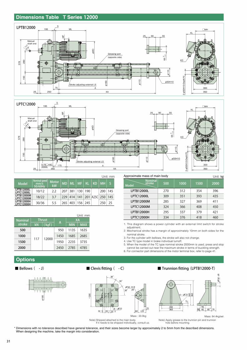
LPTB12000LLPTC12000LLPTB12000MLPTC12000MLPTB12000HLPTC12000H
500 1000 1500
270309285324295334
312351327366337376
354393369408379418
2000
396435411450421460
XA
500
1000
1500
2000
kN
117 12000
A
950
1450
1950
2450
MIN1135
1685
2235
2785
MAX1635
2685
3735
4785
207
229
265
MD
2.2
3.7
5.5
10/12
18/22
30/36
LPTB12000LLPTC12000LLPTB12000MLPTC12000MLPTB12000HLPTC12000H
381
414
403
ML
130
141
156
MF
190
201
245
KL
A25C
200
250
250
KD
145
145
25
MH S
φ180
12000
LPTB12000
LPTC12000
■ Bellows ( - J) ■ Clevis fitting ( - C) ■ Trunnion fitting (LPTB12000-T)
Note) Apply grease to the trunnion pin and trunnion hole before mounting.
Mass : 33.0kg
578 280
φMD
MF
150
25 250
A
XA
195 MLS
25 90 55KL
□MH
300
KD
φ50H10
350
φ110
φ160
φ110
2-φ50H10-Depth70
□17
650 -1.0
□17
0.75□×6C2000L
195S
ML
25 90 55
KD
KL□MH
300
350
φ50H10
XAA
35025
578
280
150
MF
φMD
φ160
φ110
φ110
2-φ50H10-Depth70
650 -1.0
Mass: 84.4kg/set
75
175
{ kNf }
Manual shaft end
Greasing port (opposite side)
Stroke adjusting external LS
Manual shaft end
Stroke adjusting external LS
Greasing port (opposite side)
Unit: mm Unit: ㎏
Unit: mm
MotorkW
Nominal speedmm/s50/60Hz
ModelNominal stroke
Model
Nominal stroke
Thrust
Note) Shipped attached to the main body.If it needs to be shipped individually, consult us.
31

1. This diagram shows a power cylinder with an external limit switch for stroke adjustment.
2. Mechanical stroke has a margin of approximately 10mm on both sides for the nominal stroke.
3. For the cylinder with bellows, the stroke will also not change.4. Use TC type model in brake individual turnoff.5. When the model of the TC type nominal stroke 2000mm is used, press and stop
cannot be carried out near the maximum stroke in terms of buckling strength.6. For connector part dimensions of the motor terminal box, refer to page 41.
XA
500
1000
1500
2000
kN
156 16000
A
1060
1560
2060
2560
MIN1260
1810
2360
2910
MAX1760
2810
3860
4910
229
265
265
MD
3.7
5.5
7.5
14.5/17.5
20/24
31/37
LPTB16000LLPTC16000LLPTB16000MLPTC16000MLPTB16000HLPTC16000H
414
403
441
ML
141
156
156
MF KL
250
KD
145
170
170
MH S
LPTB16000LLPTC16000LLPTB16000MLPTC16000MLPTB16000HLPTC16000H
500 1000 1500
469518480529490539
525574536585546595
581630592641602651
2000
637686648697658707
201
245
245
A25C
16000
LPTB16000
LPTC16000
225 MLS
30 100 65
KD
KL□MH
340
400
φ63H10
XA
A
31038
□24
659
329
170
MF
φMD
φ180
φ130
φ130
2-φ63H10-Depth75
800 -1.0
225 S ML
38 400
A
XA
φ63H10
30 100 65
KD
KL
□MH
340
400
□24
0.75□×6C2000L
659
329
MF
φMD
φ180
φ130
φ130
2-φ63H10-Depth75
170
800 -1.0
Mass: 124.6kg/set
90
180
{ kNf }
Stroke adjusting external LS
Greasing port (Manual side)
Manual shaft end
Manual shaft end
Stroke adjusting external LS
Greasing port (Manual side)
Unit: mm Unit: ㎏
Unit: mm
Nominal strokeModel
MotorkW
Nominal speedmm/s50/60Hz
Model
Nominal stroke
Thrust
■ Bellows ( - J) ■ Trunnion fitting (LPTB16000-T)■ Clevis fitting ( - C)
Note) Apply grease to the trunnion pin and trunnion hole before mounting.
Mass : 54.0kg
Note) Shipped attached to the main body.If it needs to be shipped individually, consult us.
Pow
er C
ylin
der
32

32000
LPTB32000
LPTC32000
1. This diagram shows a power cylinder with an external limit switch for stroke
adjustment.
2. Mechanical stroke has a margin of approximately 10mm on both sides for the
nominal stroke.
3. For the cylinder with bellows, the stroke will also not change.
4. For connector part dimensions of the motor terminal box, refer to page 41.
313 32000
265
265
324
MD
5.5
7.5
11
10/12
15/18
20/24
LPTB32000LLPTC32000LLPTB32000MLPTC32000MLPTB32000HLPTC32000H
403
441
519
ML KL KD
245
245
263
A25C
A25C
A30B
XA
500
1000
1500
2000
kN { kNf }
A
1315
1815
2315
2815
MIN1575
2125
2675
3225
MAX2075
3125
4175
5225
LPTB32000LLPTC32000LLPTB32000MLPTC32000MLPTB32000HLPTC32000H
500 1000 1500
121513051225131512941384
131314031323141313921482
141115011421151114901580
2000
150915991519160915881678
140 90
1250 -2.0
86 190 ML
35
(34) 285 285 A
570 XA
φ90H10
140 90
Thrust detecting port
Manual shaft end
□27
Grease discharge port
φMD
φ240
φ180
1250 -2.0
Mass: 149.2kg/set
(273)
540520
2-∅90H10 DEPTH110
2-M30
KD
KL
50
φ180
35
φ180
86 190
1133
175
590
285
415
A
Grease discharge port Grease discharge portφ
240
φ180
130
Grease port (Manual side)
(34)
ML
φMD
260
XA
φ90H10
1133
175
590
260
(273)
540520
2-∅90H10 DEPTH110
2-M30
KD
KL
Stroke adjusting external LS
50
Grease port (Manual side)
Stroke adjusting external LS
Manual shaft end
□27
Unit: mm Unit: ㎏
Unit: mm
MotorkW
Nominal speedmm/sModel
Nominal stroke
Thrust Nominal strokeModel
■ Bellows ( - J) ■ Clevis fitting ( - C) ■ Trunnion fitting (LPTB32000-T)
Note) Apply grease to the trunnion pin and trunnion hole before mounting.
Mass : 185.0kg
Note) Shipped attached to the main body.If it needs to be shipped individually, consult us.
33

The following three types of position detecting devices can be built in as your requested.
120
84(27)
126 or less
Note) Mounting cannot be carried out with clevis tting.Mount this unit with trunnion tting.
Position detecting unit
60
4362
T500T1000T2000T4000T6000T8000T12000T16000
7.37.68.09.012.213.313.314.5
Frame no. Mass
Micro switch specification
● With two switches (symbol K2) ……… Layout of micro switches LS1 and LS2 in the previous diagram
● With four switches (symbol K4) ……… Layout of micro switches LS1, LS2, LS3 and LS4 in the previous diagram
D2VW-5L2A-1M(OMRON)Equivalent
250V AC 4A(cos=0.7)
For terminal No., refer to page 110.
Optionsymbol Application example
K2
K4Note) In the table at the left
For adjustment of the operating position, operate the power cylinder to adjust the
LS cam. Loosen the hexagon socket head set screws (2 pieces) on the LS cam
with a hexagon bar wrench (nominal 1.5).
Stops with operation of the micro switch for thrust detection.
Stops with operation of the micro switch for position detection.
Detects position with operation of the micro switch for posit ion detection.
Unit: ㎏
Rotary encoder
Terminal block
SCL14B
Applicable wire diameterφ12.5~φ14Gland mounting part PF1/2
Micro switch LS4
Micro switch LS2Micro switch LS3
Micro switch LS1
Potentiometer Cam Gear head
Hexagon socket head set screw
LS cam
Pow
er C
ylin
der
34

This is a variable resistor to output electric signals depending on the stroke amount of the
cylinder. Use this unit in combination with a printed board and a stroke indication meter.
Resistance values according to the model have been adjusted before shipment.
Separately request preset values according to the model as they are described in the
position detecting unit speci cation drawing. Pay strict attention to handling because
correspondence between the stroke position and the resistance value will deviate by
rotating the rod of the power cylinder.
CP-30 or equivalentSAKAE TSUSHIN KOGYO CO., LTD.
1kΩ0.75W
1000V AC 1min.355°±5°360°endless
Connected to terminal block in position detecting unitP1 P3P2
Cylinder rod retract Cylinder rod extend
Figures in parentheses indicate terminal No.
Case0V+5V to 24VSignal ZSignal 2Signal 1
(9) (10) (11) (12) (13) (14)
a. b. c. d = T/4 ± T/8 T/2 ≦ e ≦ 3T/2
Signal 1(A-phase output)
Signal 2(B-phase output)
Signal Z(Z-phase output)
When extendingTa b c d
Maximum lead-in current 30mA (max)
e
H
H
H
L
L
L
+
out
-
Rotary encoder specificationsTS5305N251
Tamagawa Seiki Co., Ltd.600P/R
90° phase difference two-phase square wave + home position output̶
1V or less5~24V DC
HL
The output signal of the standard speci cation is of an incremental
type, however, an absolute type is also available.
The output type in standard speci cations is open collector.
If voltage output type is required, see (Note 1) below.
If the speci cation of line driver output is required, contact us.
Note 1) Due to the open collector output, output signals are obtained when the pull-up resistor is connected.Signal 1 and signal 2 are output voltages of H “(power supply voltage 1)V or more” and L “1V or less.”For the Z-phase, negative logic applies.
Reference resistance values 5V: 220 , 12V: 470 , 24V: 1k
Note 1)
Note 1)
* Best suited to controlling the stroke by a sequencer or programmable controller, etc.
More accurate positioning control is possible in combination with motor speed control by an inverter, etc.
① The standard products incorporate an incremental type encoder.
② The rotary encoder has been set to output 10 pulse per stroke of 1mm.
③ It is possible to set an accurate home position of the machine in combination with a limit switch because home position output is read out
every 600 pulses.
④ Do not apply vibration or impact to the rotary encoder because it is precision equipment.
⑤ Use shield wire for wiring to the rotary encoder.
⑥ As a guide for the distance between the rotary encoder and control panel, a collector current of 20mA should be able to be transmitted
approximately 50m (12V pull-up).
For distances other than the above, consult with us.
35

Use terminals provided in the unit for wire connection to the position detecting internal limit switch, potentiometer and rotary encoder.
COM on the internal LS means common use. (internally wire-connected)
Use shield wire for wiring to the rotary encoder.
1 2 3 4 5 6 7 8 9 10 11 12 13 14 15 16 17 18
LS1a18
b17
c4
P RLS2a5
b6
LS3a16
b15
LS4a7
b8
11
22
33
19
210
Z11
+5V~24V12
0V13 14
Equipment wiring terminal
Power cylinder wiring terminal
Terminal No.
Internal LS (K2, K4) Potentiometer Rotary encoder
Case
Option
1. Special scale and wide angle gauge are also available at your request.2. When you want to express scale in other than percentage, indicate this to us.
* A separate printed board is also required.
RM-80B(100µA DC) or equivalent
JIS C 1102 2.5 class
Frame・black
Full stroke indicated by 100%
Center of meter
4-φ4 hole
Panel cut
Printboard
Adjust the meter with an ADJUST volume on the printed board. Do
not make a mistake with the stroke indication meter +, - . Replace
the terminals 1 and 2 on the print board to set the indication meter
to 100% when the stroke is MIN.
Model LPCO-D1 (Operation power source 100/110V 50/60Hz)LPCO-D2 (Operation power source 200/220V 50/60Hz)
PI: Stroke indication meter Potentiometer
4-φ3.1 hole
Pow
er C
ylin
der
36

Wire connection is the same as that for the
st roke indicat ion meter , however, i t is
necessary to separately feed power to the
meter relay. Supply power from the operating
power supply. It is easy to connect the b
contact as an output contact to the b contact
for the stroke adjusting LS in series.
1000
LOW
CONTACT RATING (RESISTIVE) 3A 250V AC , 3A 30V DC HIGH
±
M (-)
(+)
c
b
ac
b
a
101 100
40 40
3232
83
154-M3
%
Used for simple adjustment of stroke on the operation panel.
Note) For using 4 – 20mA output, designate as “for 4 – 20mA output.”
* A separate printed board is also required.
Iron panel installation is standard. Separately
indicate to us when installing an aluminum panel.
Meter relay specifications
( )
NRC-100HL (TSURUGA) or equivalent product
JIS C 1102 2.5 class
Frame・Black
Full stroke indicated by 100%
100/100V AC, 200/220V AC 50/60Hz
100μA DC maximum
1C for both HIGH, LOW sides(refer to the following Fig.)
250V AC 3A(cosφ=1)
(Described speci cations and dimensions may be subject to change due to circumstances.)
15 or less
The main body of the power cylinder is provided with a potentiometer.The phase of a stroke deviates if the rod is rotated before installation. Therefore, cylinders with a stroke adjusting limit switch are recommended.Pre-set minimum and maximum strokes to be used with the stroke adjusting limit switch, then use the meter relay.
This is the same as the print board for the stroke indication meter.
Measuring needle
Lower limit set index (L) Upper limit set index (H)
L side relay operation
H side relay operation
Our highly reliable shock relay is recommended as an electric safety device for the power cylinder of the TB type.
For details, refer to the “TSUBAKI E&M electric overload protection devices shock monitor shock relay catalogue.”
37

There are various methods of positioning control for the power
cylinder. Positioning accuracy greatly varies depending on the
speed of the power cylinder, the size of the load, the size of a load
inertia, the operating direction (vertical, horizontal) and the wire
connection method for the brake. Control methods may be limited
depending on the operating condition. As such, what methods
there are will be conceptually described here.
① With stroke adjusting limit switch……Positioning of stroke upper
and lower limit
② With position detecting limit switch……Intermediate positioning
Accuracy generally increases with lower cylinder speed.
③ Press (pull) stop (Thrust detecting limit switch for T series TC
type is used.)
This is a method that stoppers are mechanically provided on
both ends of a stroke used for equipment driven by the power
cylinder, and press, pull stop are carried out, and then a thrust
detecting limit switch for the power cylinder is used. The stroke
is mechanically regulated by the stoppers, therefore, accurate
positioning is possible.
This method is convenient when you want to change the stroke of
the power cylinder on the control side. Accuracy generally
increases as the cylinder speed decreases. For the power cylinder
body, the method wi th a stroke adjust ing l imi t swi tch is
recommended to prevent stroke over.
This method controls stroke by a programmable controller (PC).
Use the PC with a counter. Use a limit switch to detect home
position. (For the power cylinder body, the method with a stroke
adjusting limit switch is recommended.)
①
With this method, when OFF signals for the motor and the brake
are not simultaneously outputted from the PC, and OFF signal for
the motor is outputted ear l ier , the cyl inder coasts whi le
decelerating. Highly accurate positioning is possible because the
power cylinder operates at a low speed such as output of an
operation signal for the brake just before the stop position.
②
Note that, when a heavy object is moved up or down, or a load with
a large inertia is operated, it may not be suf ciently slowed down
by any method.
B: Brake (Individual turnoff)M: MotorRE: Rotary encoderLS: Stroke adjusting external limit switch
Electromagneticcontactor
Electromagneticswitch
PC High speed counterStroke setter
Power cylinder
Home position detection
B: Brake (Individual turnoff)M: MotorP: Potentiometer
Extend,retract button
Electromagneticcontactor
Electromagneticswitch
Meter relay
Transducer
Power cylinder
B: Brake (Individual turnoff)M: MotorRE: Rotary encoderLS: Stroke adjusting limit switch
Electromagneticcontactor
InverterPC High speed counterStroke setter
Power cylinder
Home position detection
Pow
er C
ylin
der
38

0.1~0.4kW
0.1~0.4kW
0.75~3.7kW
LPTBLPTC32000
LPTBLPTC250~
LPTBLPTC16000
0.75~3.7kW
In the case of brake internal wiring
WB2
UB1
V M BRST
WB2
UB1
V M BRST
WB2
UB1
V
RST
M B
WB2
UB1
V M BRST
WB2
UB1
V M BRST
380~460V AC
WB2
UB1
V M BRST
WB2
UB1
V M BRST
200~220V AC200~220V AC
200~230V AC
R
S
T
M B
* Crimp contact bolt: M4
Power module Power module
From intermediate tap
From intermediate tap
Power side
Power side
For 5.5kW or higher,
use brake external wiring.
Power module
Power side
In the case of brake external wiring
Power module Power module
From intermediate tap
From intermediate tap
Power side
Power side
Power module Power module
Power side
Power side
5.5kW or more
Rod operatingdirection
(In the case of connection on upper surface) Rod extend Rod retract
Power side
Power module
39

WB2
UB1
V M BR
200~220V AC
200~230V AC 380~460V AC
200~220V AC
ST W
B2
UB1
V M BRST
WB2
UB1
V M BRST W
B2
UB1
V M BRST
R
S
T
M B
◎
・ If the motor is operated by the inverter, it is necessary to individually turn off the brake. When individually turning off the brake, as shown in the following diagram, remove the short piece, and do not connect wire to the brake power module from the inverter output, apply a normal power voltage. Separately provide a power supply shown in the following diagram and apply power to the brake power module. If separate power cannot be provided, decrease the voltage by a transformer. Use a transformer whose the capacity is more than necessary, and check that there is no voltage drop. And if the motor voltage of 0.1 to 0.4kW is 400V class, also remove the wire from the motor intermediate tap and insulate it.
・ If the motor voltage of 0.4kW or less is 400V class, remove the wire from the motor intermediate tap and insulate it, and separately provide a power supply of 200V to 220V and apply power to the brake power module. If there is no power source of 200V to 220V, decrease the voltage to 200V to 220V by a transformer. The capacity of the transformer shall be 90VA or more, and check that there is no voltage drop.Use an electromagnetic contactor for the brake of 200V class with a rated load of 250V AC, 7A or more. For the 400V class, use an electromagnetic contactor with a contact voltage of 400 to 440V AC, an induction load of 1A or more (e.g. electromagnetic contactor for AC motor 2.2kW). The power module includes a surge absorbing protection element. Add a protection element for the contact in each part if necessary.
・Do not put a relay contact on the output side of the standard power module (between the power module and brake coil). When carrying out [DC individual turnoff wiring] in which the relay contact is put into the position, contact us beforehand.
Power module
0.1~0.4kW
Inverter
From intermediate tap
From intermediate tap
Power module
0.1~0.4kW
Make sure to insulate.
Make sure to insulate.
Inverter
0.75~3.7kW
Power module
0.75~3.7kW
Power module
Inverter Inverter
5.5kW
Inverter
Power module
Power side
Pow
er C
ylin
der
40

0.1kW~0.4kW
0.75kW~1.5kW
2.2kW~7.5kW
11kW
A20C
A25C
A30B
φ14~φ15
φ19~φ20
φ23~φ24
PF 3/4
PF 1
PF 1・1/4
φ28
φ35
φ42
SK-14L φ11~φ13 PF 1/2 -
Stroke adjusting external LS
SCS-10B(φ8.5~φ10.5)PF1/2 SCL-14A(φ10.5~φ12.5)PF1/2 SCS-14A(φ10.5~φ12.5)PF1/2
WLCA2(OMRON) or equivalent
250V AC 10A(cosφ=0.4)
V-165-1AR5(OMRON) or equivalent
250V AC 10A(cosφ=0.4)
Thrust detecting LS
Z-15GW22-B(OMRON) or equivalent
250V AC 10A(cosφ=0.4)
4P‐0.1kW
200V50Hz
1.3(4.91)
0.72(2.76)
2.4(11.6)
2.1(10.2)
2.1(11.0)
1.1(4.68)
1.1(5.14)
1.2(5.14)
0.63(2.40)
1.1(4.88)
0.55(2.22)
1.1(5.39)
0.56(2.41)
0.62(2.60)
0.65(2.84)
0.36(1.38)
0.31(1.27)
0.32(1.41)
0.180.270.180.270.180.27
0.180.270.180.270.180.27
0.190.290.190.290.190.29
0.180.270.180.270.180.27
0.180.270.180.270.180.27
0.190.290.190.290.190.29
SBH01LP
SBH02LP
SBH04LP
200V60Hz
220V60Hz
400V50Hz
400V60Hz
440V60Hz
200V50Hz
200V60Hz
220V60Hz
400V50Hz
400V60Hz
440V60Hz
4P‐0.2 kW
4P‐0.4 kW
3.9(24.0)
3.5(22.0)
3.4(24.0)
1.9(12.0)
1.7(11.0)
1.7(12.0)
0.180.27
0.180.27
0.200.30
0.090.15
0.090.15
0.100.16SLB07LP4P‐0.75 kW
6.5(49.0)
6.1(45.0)
5.8(50.0)
3.2(24.5)
3.1(22.5)
2.9(25.0)
0.180.29
0.180.29
0.200.32
0.090.15
0.090.15
0.110.16SLB15LP4P‐1.5 kW
9.6(67.0)
9.0(59.0)
8.6(64.9)
4.8(33.5)
4.5(29.5)
4.3(32.5)
0.250.34
0.250.34
0.250.34
0.130.17
0.130.17
0.130.17TB-A2.24P‐2.2 kW
15.2(122)
14.4(104)
13.6(114)
7.6(61.0)
7.2(51.8)
6.8(57.0)
0.340.44
0.340.44
0.340.44
0.170.22
0.170.22
0.170.22TB-A3.74P‐3.7 kW
22.4(146)
21.0(125)
19.8(138)
11.2(73.0)
10.5(62.5)
9.9(68.8)
1.52.0
1.52.0
1.52.0
3.04.0
3.04.0
3.04.0TB-A7.54P‐5.5 kW
29.6(215)
28.2(185)
26.4(204)
14.8(108)
14.1(92.5)
13.2(102)
1.52.0
1.52.0
1.52.0
3.04.0
3.04.0
3.04.0TB-A7.54P‐7.5 kW
42.5(290)
41.0(249)
38.0(274)
21.5(145)
20.5(124)
19.0(137)
1.31.7
1.31.7
1.31.7
2.63.4
2.63.4
2.63.4TB-A154P‐11 kW
Note) 1. The above values are rated current values of the motor and brake. A numerical value in parentheses is a start current value of the motor.2. The rated current values and start current values do not include a brake current value.3. A DC brake is used as a brake. The upper stage of the brake current value indicates a value on the primary side of the power module, and the lower stage indicates a value on the
secondary side.4. The above values are references because the rated current values for the power cylinder vary depending on operating conditions.5. For simultaneous turnoff of 0.1kW to 0.4kW, 400V class, the voltage is converted to 200V through the motor intermediate tap to be input. For individual turnoff, decrease the voltage
to 200 to 220V by a transformer. The capacity of the transformer capacity shall be 90VA or more.6. For individual turnoff of 0.75kW or more, 400V class, the DC module is applicable for 400V class, therefore, it is unnecessary to decrease the voltage.7. For 0.75kW and 1.5kW of 400V class, the brake model Nos. are “SLB07LPV” and “SLB15LPV,” respectively.
Motor capacityShape of terminal box Shape of connector Applicable cableouter diameter
Connector partmounting dimension A
Terminal box seathole dimension B
Note) A rubber plug or plate has been inserted into the connector to prevent water etc., from intruding before shipment. Make sure to remove it when using.
(0.4kW or less)
(0.75kW or more)
For advancing For advancingFor retreating For retreatingRed
Black
White
Red
Black
White
Green
Yellow
Brown
Green
Yellow
Brown
Thrust detecting LS (LPT16000 or smaller)
・
Outputframe No.
Motor current value (A) Brake current value (A)Brake
model No.
A
B
A
41

LS01: Stroke adjusting external limit switch for extending
LS21: Thrust detecting limit switch for extending
LS02: Stroke adjusting external limit switch for retracting
LS22: Thrust detecting limit switch for retracting
NOTE:(1) This diagram is an example when the thrust detecting limit switch
is used for overload protection.(2) This diagram shows a single-acting circuit. When using in an
inching circuit, remove wire connection between N1 and N2, N3 and N4 and short-circuit the PBS.
(3) If the power source voltage for the motor is different from the control voltage, place a transformer into a portion in the diagram.
(4) The lead wires B1 and B2 for the brake are connected to the motor terminal blocks U and W using short pieces.
(5) When individually turning off the brake, remove the short piece and apply a normal power source voltage other than inverter output to B1 and B2 from the outside.
NOTE:
LS111: LPNo.1 Stroke adjusting external limit switch for extending LS1
LS112: LPNo.1 Stroke adjusting external limit switch for retracting LS1
LS211: LPNo.2 Stroke adjusting external limit switch for extending LS2
LS212: LPNo.2 Stroke adjusting external limit switch for retracting LS2
* For reference circuit for the type of 0.4kW or less.
Brake motor
OCRMCF
MCR
C BRST
F
PL
PBS LS21
LS22
LS01
LS02
N1
N3
PBF PBR
MCF
MCR
MCR
MCF
N2
N4
MCF
MCR
OCR
B1
B2
UVW
M B
MCB1
MCF1 OCR1
OCR2
MCR1
MCF2
MCB1
MCR2
C B
F
PL
PBS PBF PBR ARR
ARF
ARF
ARR
ARF
ARR
OCR1 OCR2
LS111
LS112
LS211
LS212
MCR1
MCF1
MCR2
MCF2
ARF
ARR
MCF1
MCR1
MCF2
MCR2
Brake motor
Brake motor
M B
M B
B1
B2
UVW
B1
B2
UVW
Power module
Power module
RST
Power module
Power
Power
(1) This diagram is an example of 0.75kW or more brake individual turnoff two units inching multiple circuit.
(2) If the power source voltage for the motor is different from the control voltage, place a transformer into a portion in the diagram.
(3) As the brake terminal blocks B1 and B2 are connected to the motor terminal blocks U and W using short pieces, remove the short pieces before use.
(4) Apply a normal power source voltage other than inverter output to B1 and B2 from the outside.
Pow
er C
ylin
der
42

* For the mount tting, refer to the item of options.
Although the electromagnet stroke (gap) of the brake has been
adjusted to approximately 1.2 through 1.3mm (limit gap 1.5mm) for
0.4kW or less or to approximately 0.2mm (limit gap 0.5mm) for
0.75kW or more, re-adjust it before it exceeds the limit gap value.
Any of horizontal, vertical and inclined direction is allowed.
For installation of the main body, use a trunnion mount or clevis
mount (parallel only).
Apply grease to the trunnion pin and the bracket hole before
mounting.
Install the end part with a U-type orⅠ-type end tting.
Use the ball screw as it is because it has been lubricated with grease in advance. Re ll grease with reference to Table 1-2 as a guide. To apply grease to the ball screw, remove the greasing port bolt on the outer cylinder and advance the rod in the full stroke and apply grease to the outer circumference of the screw with a grease gun, and then reciprocate the rod within the stroke to be used. Repeat this operation a few times.
Never insert your nger into the greasing port.
If the cylinder operates with your nger inserted, your nger
may be injured.
* The above greases are lled before shipment.Note) JWGS100G is separately sold in a container of 100g.
Useclassification Grease name
JWGS100G
*DAPHNE EPONEX SRNo.2
NIGULUBE EP-2K
MOBILUX EPNo.2
COSMO GREASE DINAMX EPNo.2
SHELL ALBANIA EP grease 2
Company name
When manually adjusting the stroke, rotate the manual handle shaft
on the reducer part with a monkey wrench or a socket wrench after
releasing the brake for the brake motor.
When load is applied to the rod, remove the load before
releasing the brake.
For the amount of movement of the rod per one turn of the manual
shaft, refer to the standard model list (page 9).
1. Anti-rod rotation is required because a rotating force is
generated on the rod with thrust (refer to page 9). Generally,
rotation can be mostly prevented by installing the rod end to a
driven machine.
2. When operating with the end set free or in the case of
application to install pulleys to pull a rope, a rod anti-rotation is
normally required.
・ Take a coasting amount into consideration for adjustment of the
limit switch.
・ When using the cylinder at the nominal stroke 100%, set the limit
switch so that the cylinder stops within the XA dimension in the
Dimensions Table.
・ When simultaneously operating two or more power cylinders,
install a limit switch at the upper limit and lower limit on each
cylinder.
Install the power cylinder so as to prevent bending load (lateral
load) from acting on the rod.
For the gear and the bearing in the reducer part, the gear case is lled with grease. Accordingly, it is not necessary to grease
because they normally endure use for one year or longer. However, operation for a long time or use after long storage impairs the lubrication effect due to deterioration of grease. Therefore, inspect and grease.Reducer part initial lled grease
Gear case: DAPHNE EPONEX SRNo.1 IDEMITSU KOSANPlanetary gear (straight type): Moly gear grease No. 1 SUMICO
LUBRICANT CO., LTD.
Note) The above values are for longer use, and do not indicate the life.
Operating frequency Lubrication cycle
500 to 1000 times/day
100 to 500 times/day
10 to 100 times/day
Three to six months
Six months to one year
One to one and half year
Decelerating part Ball screw part
Brake
43

● Anti-rod rotation is required because a rotating force is exerted on the rod with thrust. Rod rotating forces at the rated thrust are described in the model list. When operating with the end unconnected or when installing pulleys to pull rope, use an optional rod anti-rotation speci cation.
● When the cylinder operating stroke is short, a high speed type cylinder cannot be used because the operating time per one stroke becomes shorter and cannot be actually controlled. The following table shows minimum necessary strokes when motor energization time is 0.5s. Refer to this table to determine the speed.
● Apply grease to the trunnion pin and the trunnion hole for trunnion mounting.● Also, apply grease to the connecting pin of the end tting and the connecting pin for clevis mounting.● When the main body greatly swings by operation of the cylinder, consider using a sliding bearing or a rolling
bearing for the connecting part. Cylinders whose trunnion hole is provided with sliding bearing are available as MTO.
● When the trunnion pin or connecting pin for the clevis or the end tting is directed in the vertical direction (when the cylinder is laid horizontally), and the main body swings, take countermeasures for wear such as inserting a bearing member into the trunnion hole, the clevis tting, or the side part of the end tting.
● All models are totally enclosed structures so that they can be used normally outdoors, however, under adverse conditions exposed to constant water and steam etc., and snow accumulation, although they are an outdoors type, an appropriate cover is required. The power cylinder can generally be used in a range of -15℃ to 40℃, although it varies depending on the use conditions. When using at 40℃ or higher, always protect with a heat insulating cover, etc. Never use in a ammable atmosphere, otherwise it may cause an explosion and re. In addition, avoid using it in a location where vibration or shock exceeding 1G is applied.
● When using a cylinder of the cabtire cable lead wire speci cation outdoors, carry out waterproo ng treatment suf ciently.
● Regulate the both ends of the stroke by the limit switch. Select a type of option which allows the limit switch to be mounted on the power cylinder body.
● Use within the stroke range. If the stroke is exceeded, breakage may occur.● As a high-speed type (H speed) of the power cylinder T series has a long coasting distance, the striker may
override the limit switch. For this reason, make sure to allow a limit signal to be self-held on the control circuit.● Megger testing is prohibited for this cylinder. It may break the built-in power module. Remove the brake wiring
for the terminal block when conducting megger testing of the external circuits.● Adjustment of the limit switch for thrust detection of the TC type must not be carried out by the customer. The
preset value for thrust detection may greatly change.
Speed symbol
Nominal speed mm/s 50/60Hz
0.5s operation moving amount mm
Predicted maximum coasting amount mm (Reference)
Minimum necessary stroke mm 74/93 or more
Pow
er C
ylin
der
44

Your name:Company name:
TEL :
Address:
(〒 - )
FAX :
3-phase 200V/50Hz、200V/60Hz、220V/60Hz
3-phase 400V/50Hz、400V/60Hz、440V/60Hz
Brake, Outdoors, Explosion-proof
times/min x min/hrs. x hrs./day x days/yr.
(Back and forth count as 2)
Stroke adjustment external LS, Thrust detection LS,
Internal LS, Potentiometer, Rotary Encoder
℃
Indoor, Outdoors, Explosion-proof
Average, High
Others
Others
Layout Other information
Others
Others
Others
Sta
ndar
Sp
eci
catio
nE
lect
ric M
otor
O
per
atin
g E
nviro
nmen
t
1. Application load (thrust) Normal operation N{kgf} Max N{kgf}
2. Speed mm/s (at 50Hz, 60Hz)
3. Stroke
4. Power
5. Special Speci cation
6. Operation
7. Ambient Temperature
8. Mounting Location
9. Dust
10. Control Device
Actual stroke mm Max stroke mm
Trunnion tting, crevice tting, Ⅰ-shape end tting11. Others
Inform TSUBAKI E&M of the following items when making an inquiry.
45

●●●●●・ ・
・ ・
●●●●
●
●

U.S. TSUBAKI POWER TRANSMISSION, LLC301 E. Marquardt Drive, Wheeling, IL 60090, U.S.A.
Phone : +1-847-459-9500
URL : http://www.ustsubaki.com
TSUBAKI of CANADA LIMITED1630 Drew Road, Mississauga, Ontario, L5S 1J6, Canada
Phone : +1-905-676-0400
URL : http://tsubaki.ca
TSUBAKI BRASIL EQUIPAMENTOS INDUSTRIAIS LTDA.R. Pamplona, 1018, CJ. 73/74, Jd. Paulista
CEP 01405-001, São Paulo, S.P.Brazil
Phone : +55-11-3253-5656
URL : http://tsubaki.ind.br
TAIWAN TSUBAKIMOTO CO.No. 33, Lane 17, Zihciang North Road
Gueishan Township Taoyuan County Taiwan R.O.C.
Phone : +886-3-3293827/8/9
URL : http://tsubakimoto.com.tw
TSUBAKIMOTO SINGAPORE PTE. LTD.25 Gul Lane, Jurong, Singapore 629419
Phone :+65-6861-0422/3/4
URL : http://tsubaki.sg
TSUBAKI AUSTRALIA PTY. LTD.Unit E, 95-101 Silverwater Road
Silverwater NSW 2128, Australia
Phone : +61-02-9704-2500
URL : http://tsubaki.com.au
TSUBAKIMOTO CHAIN (SHANGHAI) CO. LTD.Room 601, Urban City Centre, 45 Nanchang Road
Huangpu District, Shanghai 2000020,
People's Republic of China
Phone :+86-21-5396-6651/2
URL : http://chunben.com
TSUBAKIMOTO (THAILAND) CO. LTD.388 Exchange Tower, 19th Floor Unit 1902
Sukhumvit Road, Klongtoey, Bangkok 10110, Thailand
Phone : +66-2-262-0667/8/9
URL : http://tsubaki.co.th
TSUBAKI INDIA POWER TRANSMISSION PTE. LTD.Chandrika Chambers No.4, 3rd Floor, Anthony Street
Royapettah, Chennai, Tamil Nadu 600014, India
Phone :+91-44-4231-5251
URL : http://tsubaki.sg
PT. TSUBAKI INDONESIA TRADINGWisma 46 - Kota BNI, 24th Floor, Suite 24.15
Jl. Jend. Sudirman, Kav. 1, Jakarta 10220, Indonesia
Phone :+62-21-571-4230/31
URL : http://tsubaki.sg
TSUBAKI POWER TRANSMISSION (MALAYSIA) SDN. BHD.No. 22, Jalan Astaka U8/84A, Bukit Jelutong Industrial Park
Section U8, 40150 Shah Alam, Selangor, Malaysia
Phone : +60-3-7859-8585
URL : http://tsubaki.sg
Vietnam Representative OfficePhone : +84-8-3999-0131/2 New Zealand Branch
Phone : +64-275-082-726
Group companies
ASIA and OCEANIA
TSUBAKIMOTO EUROPE B.V.Aventurijn 1200, 3316 LB Dordrecht, The Netherlands
Phone : +31-78-620-4000
URL : http://tsubaki.eu
OOO "TSUBAKI KABELSCHLEPP"Prospekt Andropova 18, Building 6
115432 Moscow, Russia
Phone : +7-499-418212
URL : http://tsubaki.eu
TSUBAKIMOTO U.K. LTDOsier Drive, Sherwood Park, Annesley, Nottingham
NG15 0DX, United Kingdom
Phone : +44-1623-688-700
URL : http://tsubaki.eu
TSUBAKI DEUTSCHLAND GmbHASTO Park Oberpfaffenhofen, Friedrichshafener Straße 1
D-82205, Gilching, Germany
Phone : +49-8105-7307100
URL : http://tsubaki.eu
EUROPE
NORTH and SOUTH AMERICA
HeadquartersNakanoshima Mitsui Building
3-3-3 Nakanoshima, Kita-ku
Osaka, 530-0005, Japan
Phone : +81-6-6441-0011
URL : http://tsubakimoto.com
Chain & Power Transmission Sales1-3 Kannabidai 1-chome
Kyotanabe,
Kyoto, 610-0380, Japan
Phone : +81-774-64-5022
©2014/3 TSUBAKIMOTO CHAIN CO. Printed in JapanNote: In accordance with the policy of TSUBAKIMOTO CHAIN CO. to constantly improve its products, the specifications in this catalog are subject to change without notice.