tsgs#6(99)551 - 3gpp
TRANSCRIPT

Technical Specification Group Services and System Aspects TSGS#6(99)551Meeting #6, Nice, France, 15-17 December 1999
Source: TSG SA WG2Title: CRs on 23.121 v 3.1.0Agenda Item: 5.2.3
The following CRs have been approved by TSG SA WG2 and are requestedto be approved by TSG SA plenary #6.
On 23.121 v.3.1.0TDoc # CR # spec Title cat
S2-99B81 042r1 23.121 Gateway Location Register CS2-99B58 043r1 23.121 Clarification of SMS sending in UMTS FS2-99B63 044r1 23.121 SRNS Relocation for PS domain for the case of RT CS2-99E63 045r1 23.121 Cell Broadcast System Architecture BS2-99B61 046r1 23.121 Additional modifications related to UMTS area concept changeCS2-99C02 047 23.121 Correction of criteria for data volume reporting from RNC to SGSNFS2-99D31 051 23.121 Mobile IP BS2-99E06 052 23.121 Termination point of the GTP-U tunnel F

3GPP/SMG Meeting #9 Document S2-99B81Location, Country, 25-29 OCT 1999 e.g. for 3GPP use the format TP-99xxx
or for SMG, use the format P-99-xxx
CHANGE REQUEST Please see embedded help file at the bottom of thispage for instructions on how to fill in this form correctly.
Current Version: 3.1.023.121 CR 042r1GSM (AA.BB) or 3G (AA.BBB) specification number ↑ ↑ CR number as allocated by MCC support team
For submission to: SA#6 for approval X strategic (for SMGlist expected approval meeting # here ↑ for information non-strategic use only)
Form: CR cover sheet, version 2 for 3GPP and SMG The latest version of this form is available from: ftp://ftp.3gpp.org/Information/CR-Form-v2.doc
Proposed change affects: (U)SIM ME UTRAN / Radio Core Network X(at least one should be marked with an X)
Source: FUJITSU Date: 26/10/99
Subject: Gateway Location Register
Work item:
Category: F Correction Release: Phase 2A Corresponds to a correction in an earlier release Release 96
(only one category B Addition of feature Release 97shall be marked C Functional modification of feature X Release 98with an X) D Editorial modification Release 99 X
Release 00
Reason forchange:
The CN2 group started stage 2 and 3 work on GLR concept for R99, therefore the content ofchapter 4.1 on GLR concept in 23.920 has been removed. This CR proposes to add the removedsection to TS 23.121 as annex.
Clauses affected: AnnexNew Section
Other specs Other 3G core specifications → List of CRs:affected: Other GSM core specifications → List of CRs:
MS test specifications → List of CRs:BSS test specifications → List of CRs:O&M specifications → List of CRs:
Othercomments:
help.doc
<--------- double-click here for help and instructions on how to create a CR.

Annex A (Informative)Reduction of UMTS signalling
A.1.1 GLR Concept
The benefits of the Gateway Location Register (GLR) is theare: reduction in signalling traffic between networks. GLRis an optional network element which shall not does not change affect the MAP protocol.
• potential enhancements to mobile terminated call handling
A.1.1.1 Overview of the GLR Concept
The GLR is a node between the VLR and the HLR, which may be used to optimise the handling of subscriber locationdata across network boundaries.
In Figure 1, the GLR interacts with HLRa and VLRb for roamers on Network B. The GLR is part of the roamingsubscriber's Home Environment. When a subscriber to HLRa is roaming on Network B the GLR plays the role of anHLR towards VLRb and the role of a VLR towards HLRa. The GLR handles any location change between differentVLR service areas in the visited network without involving HLRa.
Figure 1: GLR Overview
The sequence of events when the subscriber roams to network B is as follows:
• VLRb sends the registration message to HLRa via the GLR, (i.e. HLRa stores the GLR's SCCP address and theGLR stores VLRb's SCCP address).
• HLRa returns the subscriber profile data
• The subscriber profile is stored in the GLR and VLRb
As the roaming subscriber moves between VLRs in network B, then the GLR is updated, but no message is sent toHLRa, therefore the number of messages between Network A and Network B is reduced. The reduction in signallingtraffic is a significant benefit when the two networks are far apart, e.g. between Europe and Japan.
Network A Network B
HLRa HLRb
GLR
VLRb

3
A.1.1.2 Applications of the GLR
In addition to reducing the amount of mobility related signalling between networks, theGLR's function might also be extended to other aspects. These include thefollowing:
• Enhancements for mobile terminated call handling
• Support for the Virtual Home Environment of a roaming subscriber
• Reduction of CAMEL signalling traffic between the visited and home network
• Hiding local variations in signalling between networks
• Further study is needed on these issues

3GPP TSG-SA meeting #9 Document S2-99B58London, UK, 25 th-29th October 1999
3G CHANGE REQUEST Please see embedded help file at the bottom of thispage for instructions on how to fill in this form correctly.
Current Version: 3.1.023.121 CR 043r13G specification number ↑ ↑ CR number as allocated by 3G support team
For submision to TSG SA#6 for approval X (only one box should
list TSG meeting no. here ↑ for information be marked with an X)
Form: 3G CR cover sheet, version 1.0 The latest version of this form is available from: ftp://ftp.3gpp.org/Information/3GCRF-xx.rtf
Proposed change affects: USIM ME X UTRAN Core Network X(at least one should be marked with an X)
Source: Nokia Date: 28/10/99
Subject: Clarfication of SMS sending in UMTS
3G Work item: UMTS R99
Category: F Correction XA Corresponds to a correction in a 2G specification
(only one category B Addition of featureshall be marked C Functional modification of featurewith an X) D Editorial modification
Reason forchange:
Currently 23.121 defines, that SMS sub-layer uses services of the RRC directly to sendSMS on C-plane. However, for the CS-domain SMS uses service of the MM similarlythan already defined in GSM. Also, for the PS-domain similar service request procedurehas been approved for GMM in order to establish a secure connection between UE and3G-SGSN. This CR proposes to clarify the issue in 23.121 and to remove anypossibilities for inconsistency between different specifications.
Clauses affected:
Other specs Other 3G core specifications → List of CRs:affected: Other 2G core specifications → List of CRs:
MS test specifications → List of CRs:BSS test specifications → List of CRs:O&M specifications → List of CRs:
Othercomments:
help.doc
<--------- double-click here for help and instructions on how to create a CR.

2 3G 23.121 Version 3.1.0 (YYYY-MM)
4.9 Short Message Service for UMTSUMTS will continuously support Short Message Service which already exists for GSM/GPRS system.
4.9.1 Protocols and architecture
When assuming that there is no LLC for the PS Domain Layer2 protocol, The LLC layer is only applicable for GPRSand not for UMTS. Due to that there is a need to reconsider the functionality which had been is done at LLC in GPRS.There are two alternative described below.
• Use U-plane as the alternative of LLC functionality.
•
• Use C-plane as the alternative of LLC functionality.
It is too much to establish U-plane connection to transfer small amount of data when focusing on the resource of theentire system.
If C-plane was used for data transfer, it can save resource compared with establishing U-plane connection(by usingcommon channel, efficient use of radio resource is possible). It also possess the advantage of making it possible to usesame SMS transfer procedure for CS domain and PS domain. Therefore, it comes to a conclusion that the C-planeshould shall be used for SMS transfer in UMTS system.
The C-plane is a signalling connection between UE and MSC or SGSN, respectively. Establishment of a securesignalling connection is offered by the GMM in the PS domain and by the MM in the CS domain. SMS is a user of thatsecure signalling connection.
AAL5
RANAPSCCP
Relay
RRCRLC
MAC
L1
RANAPSCCP
AAL5
Uu IuUE RNS MSC/
SGSNN
SignallingBearer
RRCRLC
MACSignalling
Bearer
ATM
L1
ATM
SMS /GMM / MM
SMS /GMM / MM
AAL5
RANAPSCCP
Relay
SMS
RRCRLC
MAC
L1
SMS
RANAPSCCP
AAL5
Uu IuMS RNS MSC/
SGSN
SignallingBearer
RRCRLC
MACSignalling
Bearer
ATM
L1
ATM
Figure 53 : Protocol architecture for 3G SMS for both a CS service domain and a PS service domain

3GPP TSG SA meeting # 10 Document S2-99E63Abiko, Japan, 29 Nov - 03 Dez 1999 e.g. for 3GPP use the format TP-99xxx
or for SMG, use the format P-99-xxx
CHANGE REQUEST Please see embedded help file at the bottom of thispage for instructions on how to fill in this form correctly.
Current Version: 3.1.023.121 CR A45r1GSM (AA.BB) or 3G (AA.BBB) specification number ↑ ↑ CR number as allocated by MCC support team
For submission to: SA#6 for approval X strategic (for SMGlist expected approval meeting # here ↑ for information non-strategic use only)
Form: CR cover sheet, version 2 for 3GPP and SMG The latest version of this form is available from: ftp://ftp.3gpp.org/Information/CR-Form-v2.doc
Proposed change affects: (U)SIM ME UTRAN / Radio X Core Network X(at least one should be marked with an X)
Source: CBS Drafting Group (Alcatel, Ericsson, Nokia,Siemens, Telia, Mannesmann)
Date: 30.11.1999
Subject: Cell Broadcast System Architecture
Work item:
Category: F Correction Release: Phase 2A Corresponds to a correction in an earlier release Release 96
(only one category B Addition of feature X Release 97shall be marked C Functional modification of feature Release 98with an X) D Editorial modification Release 99 X
Release 00
Reason forchange:
The responsibilities for the cell broadcast specification are clarified now and work hasstarted in RAN and T. RAN3 has considered the CBC-RNC protocol as part ofRelease 99. Therefore the Cell Broadcast Architecture described in the 23.920 shouldisbe moved to 23.121 with additional clarification. This CR covers the needed changes.In addition some editorial changes are proposed:Main Changes:� Clarification of the role of the BC reference point and the relation between the RNC
and the CBC� Deletion of the section on the common communication channel� Option for second CBC for LCS
Editorial Changes:� Short Message Service Cell Broadcast Æ Cell Broadcast Service� References to GSM 03.41 Æ 3G TS 23.041� Open Issues section deleted because transfered to RAN3� Responsibility section deleted because transfered to ICG Plan
Clauses affected: 4.5.1 (new), 4.10 (new)
Other specs Other 3G core specifications X → List of CRs: 23.920affected: Other GSM core specifications → List of CRs:
MS test specifications → List of CRs:BSS test specifications → List of CRs:O&M specifications → List of CRs:
Othercomments:

help.doc
<--------- double-click here for help and instructions on how to create a CR.

3G TS 23.121 version 3.1.0 (1999-10)
3GPP
3
4.5 Core network layer 3In UMTS/GPRS, it should be possible for operators to use different packet switching protocol (e.g. ATM-SVC) undersingle GTP standard.
Between GSNs GTP uses UDP/IP (or TCP/IP) for addressing regardless whether IP routing or ATM-SVC switching isused. The use of ATM-SVC will not impact on GTP standardisation. “
User IP
GTP
UDP / TCP
IP Addressing of SGSN/GGSN
Operator’s selection ATM-SVC Routing capability
Figure 4-41: Core network layer 3
4.5.1 Common Communication Channel
A common communication channel (name to be defined) provides nodes of the Core Network the ability toreach every RNC of the UTRAN. This communication channel can be used for application like SMS cellbroadcast or location services (LCS).
This communication mechanism would use e.g. an IP routing functionality of the 3G-SGSN. The accordingprotocol stack is outlined in figure 1.
Figure 4-42: Protocol Stack of the Common Communication Channel
The placeholder Xx should be replaced by the according reference points of the applications e.g. Bc for cellbroadcast.The following issues until now are identified and have to be solved:1.IP Routing functionality in the 3G-SGSN,2.An appropriated layer 3 protocol has to be chosen (TCP or UDP) per application,
L2
IP
L1
AAL5
IP
TCP/UDP
ATM
RNC Routing Node(e.g. 3G-SGSN)
ApplicationNode
L2
IP
L1
AAL5
IP
ATMIu Xx
Appl. Appl.
TCP/UDP
3G TS 23.121 version 3.1.0 (1999-10)
3GPP
4
3.Addressing of the Application and Application node by the RNC(s),4.Addressing (dynamic or static) of the application (e.g. CBC) on the RNC(s).

3G TS 23.121 version 3.1.0 (1999-10)
3GPP
5
4.9 Short Message Service for UMTSUMTS will continuously support Short Message Service which already exists for GSM/GPRS system.
4.9.1 Protocols and architecture
When assuming that there is no LLC for the PS Domain Layer2 protocol, there is a need to reconsider the functionalitywhich had been done at LLC in GPRS. There are two alternative described below.
• Use U-plane as the alternative of LLC functionality.
• Use C-plane as the alternative of LLC functionality.
It is too much to establish U-plane connection to transfer small amount of data when focusing on the resource of theentire system.
If C-plane was used for data transfer, it can save resource compared with establishing U-plane connection(by usingcommon channel, efficient use of radio resource is possible). It also possess the advantage of making it possible to usesame SMS transfer procedure for CS domain and PS domain. Therefore, it comes to a conclusion that the C-planeshould be used for SMS transfer in UMTS system.
AAL5
RANAPSCCP
Relay
SMS
RRCRLC
MAC
L1
SMS
RANAPSCCP
AAL5
Uu IuMS RNS MSC/
SGSN
SignallingBearer
RRCRLC
MACSignalling
Bearer
ATM
L1
ATM
Figure 4-45: Protocol architecture for 3G SMS for both a CS service domain and a PS service domain
4.10 Short Message Service Cell Broadcast Service in UMTSThe Short Message Service Cell Broadcast Service (SMS.CBS) was is defined as a UMTS Phase 1R99 requirement toguarantee the continuity of the corresponding GSM services. It shall be provided seamlessly (as far as the user or theusers terminal equipment is concerned) across the UMTS and GSM network.
4.10.1 Network Architecture
Figure 204-46 proposes a straight forward adoption of the GSM cell broadcast architecture in UMTS.
The basic network structure replaces the GSM BSS with the UTRAN containing the RNC and the Node B. The cellbroadcast center (CBC) is part of the core network and connected to a routing node e.g. a 3G SGSN via the Bc referencepoint to the RNC. Thus the CBC can reach every RNC via the user plane of the Iu interface by using the newlyintroduced common communication channel. On the logical interface between the CBC and the RNC a mandatoryprotocol shall be defined. to to meet the requirements defined in 3GPP TS 23.041.which should mainly be adoptedfrom the corresponding GSM specification (see GSM 03.41). The other UTRAN related interfaces are described in theaccording UTRAN specifications based on the RAN 2 TR 25.925. Based on this architecture and the currentrequirements for cell broadcast the core network elements like MSC, VLR, HLR etc are not involved for the servicedelivery.
3G TS 23.121 version 3.1.0 (1999-10)
3GPP
6
Uu
CellBroadcast
Center
(CBC)
UTRAN
RNCNode B
Node BUE
UE
1
Iub
Bc
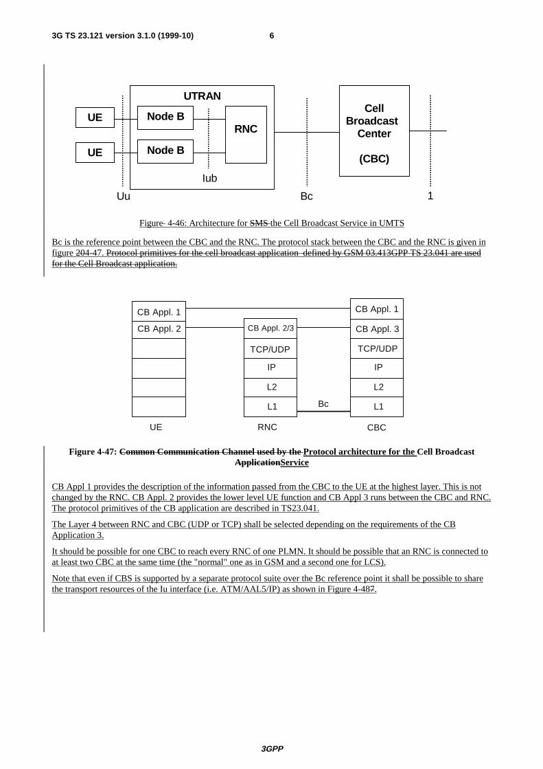
Figure 4-46: Architecture for SMS the Cell Broadcast Service in UMTS
Bc is the reference point between the CBC and the RNC. The protocol stack between the CBC and the RNC is given infigure 204-47. Protocol primitives for the cell broadcast application defined by GSM 03.413GPP TS 23.041 are usedfor the Cell Broadcast application.
L2
IP
L1
L2
IP
TCP/UDP
L1
RNC CBC
Bc
CB Appl. 2/3 CB Appl. 3
TCP/UDP
UE
CB Appl. 2
CB Appl. 1CB Appl. 1
Figure 4-47: Common Communication Channel used by the Protocol architecture for the Cell BroadcastApplicationService
CB Appl 1 provides the description of the information passed from the CBC to the UE at the highest layer. This is notchanged by the RNC. CB Appl. 2 provides the lower level UE function and CB Appl 3 runs between the CBC and RNC.The protocol primitives of the CB application are described in TS23.041.
The Layer 4 between RNC and CBC (UDP or TCP) shall be selected depending on the requirements of the CBApplication 3.
It should be possible for one CBC to reach every RNC of one PLMN. It should be possible that an RNC is connected toat least two CBC at the same time (the "normal" one as in GSM and a second one for LCS).
Note that even if CBS is supported by a separate protocol suite over the Bc reference point it shall be possible to sharethe transport resources of the Iu interface (i.e. ATM/AAL5/IP) as shown in Figure 4-487.

3G TS 23.121 version 3.1.0 (1999-10)
3GPP
7
L2
IP
L1
AAL5
IP
TCP/UDP
ATM
RNC Routing Node(e.g. 3G-SGSN)
CBC
L2
IP
L1
AAL5
IP
ATMIu
CB Appl. 2/3 CB Appl. 3
TCP/UDP
UE
CB Appl. 2
CB Appl. 1CB Appl. 1
Figure 4-47820: Common Communication Channel used by the Cell Broadcast ApplicationPossible mapping ofthe Bc reference point onto the transport resources of the Iu interface

3GPP TSG-SA2 meeting #9 Document S2-99B63(revision of S2-
99B12)London, England,10/ 1999
CHANGE REQUEST Please see embedded help file at the bottom of thispage for instructions on how to fill in this form correctly.
Current Version: 3.1.023.121 CR 044r1GSM (AA.BB) or 3G (AA.BBB) specification number ↑ ↑ CR number as allocated by MCC support team
For submission to: SA#6 for approval X strategic (for SMGlist expected approval meeting # here ↑ for information non-strategic use only)
Form: CR cover sheet, version 2 for 3GPP and SMG The latest version of this form is available from: ftp://ftp.3gpp.org/Information/CR-Form-v2.doc
Proposed change affects: (U)SIM ME UTRAN / Radio Core Network X(at least one should be marked with an X)
Source: Alcatel Date: 27/10/99
Subject: SRNS Relocation for PS domain for the case of RT
Work item:
Category: F Correction Release: Phase 2A Corresponds to a correction in an earlier release Release 96
(only one category B Addition of feature Release 97shall be marked C Functional modification of feature X Release 98with an X) D Editorial modification Release 99 X
Release 00
Reason forchange:
Current TS 23.121 describes mainly SRNS Relocation procedure in case of PS domain non realtime data service with high reliability. The case of Real Time services needs also to bedescribed.
Clauses affected: 4.3.12.2.3 SRNS relocation (UE connected to a single CN node, 3G_SGSN)followed by Location Registration in new Location Area.
Other specs Other 3G core specifications → List of CRs:affected: Other GSM core specifications → List of CRs:
MS test specifications → List of CRs:BSS test specifications → List of CRs:O&M specifications → List of CRs:
Othercomments:
help.doc
<--------- double-click here for help and instructions on how to create a CR.

TS 23.121 v3.0.0
ETSI
2
4.3.12.2.3 SRNS relocation (UE connected to a single CN node, 3G_SGSN) followed byLocation Registration in new Location Area
[The beginning of the section is not modified up to Figure 4-27 included]
"Resource reservation" Phase
During this phase, the transmission of packets between GGSN and UE through the source SRNC goes on.
1) UTRAN (source SRNC) makes the decision to perform the Serving RNC relocation procedure. Thisincludes decision on into which RNC (Target RNC) the Serving RNC functionality is to be relocated. Thesource SRNC sends SRNC Relocation required messages to the SGSN1. This message includes parameterssuch as target RNC identifier and an information field that shall be passed transparently to the target RNC.
2) Upon reception of SRNC Relocation required message the SGSN1 determines from the receivedinformation that the SRNC relocation will (in this case) result in change of SGSN.The SGSN will then send a Forward SRNC relocation request to the applicable SGSN, SGSN2, includingthe information received from the Source SRNC and necessary information for the change of SGSN (e.g.MM context, PDP context). The PDP context information contains the list of the PDP context (includingPDP type, requested / negotiated QoS) currently established by the UE along with the address of theassociated GGSN. It does not contain any information linked with packet transmission (sequence numbers)because such information is under the responsibility of the UTRAN
3) The SGSN2 sends a SRNC Relocation Request message to the target RNC. This message includesinformation for building up the SRNC context, transparently sent from Source SRNC (e.g. UE id., no ofconnected CN nodes, UE capability information), and directives for setting up Iu user plane transportbearers.When the Iu user plane transport bearers have been established, and target RNC completed its preparationphase, SRNC Relocation Proceeding 1 message is sent to the SGSN2. The SRNC Relocation Proceeding 1message contains the IP address(es) (possibly one address per PDP context) on which the target RNC iswilling to receive these packets.
4) When the traffic resources between target RNC and SGSN2 has been allocated and the SGSN2 is ready forthe SRNC move, then the Forward SRNC Relocation Response is sent from SGSN2 to SGSN1. Thismessage indicates that necessary resources have been allocated for the SRNC relocation: SGSN2 / targetRNC are ready to receive from source SRNC the downstream packets not yet acknowledged by UE. TheForward SRNC Relocation Response message contains the IP address(es) that were given in the SRNCRelocation Proceeding 1 message.
5) When the Forward SRNC Relocation Response has been received in the SGSN1, the SGSN1 indicates thecompletion of preparation phase at the CN PS domain side for the SRNC relocation by sending the SRNCRelocation Proceeding 2 message to the Source RNC. . This message contains the IP address(es) (possiblyone address per PDP context) on which to send the downstream packets not yet acknowledged by UE.
"Actual hand-over of Serving RNC" Phase
6) When the source RNC has received the SRNC Relocation Proceeding 2 message, the source RNC sends aSRNC Relocation Commit message to the target RNC(list of (SNU, UP_RLC_ack, SND)). SND is the GTPsequence number for the next downlink packet received from the GGSN. SNU is the GTP sequence numberfor the next uplink packet to be tunnelled to the GGSN. UP_RLC_Ack contains the acknowledgements forupstream PDU received by the source SRNC on each Non Real Time RLC connection used by the UE (i.e.the Receive State Variable V(R) for all RLC SAPI in acknowledged mode). For Real Time connections(conversationbal and streaming QoS class), UP_RLC_ACK is not used. The source SRNC starts a timer T3-TUNNEL , stops the exchange of the packets with the UE (point (a)), and starts tunnelling the buffereddownstream packets towards the target SRNC. The target RNC executes switch for all bearers at the earliestsuitable time instance.
7) The target RNC starts acting as SRNC. The target SRNC :
• Restarts the RLC connections. This includes, for Non Real Time bearers, the exchange between thetarget SRNC and the UE of the UP_RLC_Ack and DOWN_RLC_ACK. DOWN_RLC_ACK confirmsall mobile-terminated packets successfully transferred before the start of the relocation procedure. IfDOWN_RLC_ACK confirms reception of packets that were forwarded from the source SRNC, thenthese packets shall be discarded by the target SRNC. UP_RLC Ack confirms all mobile-originatedpackets successfully transferred before the start of the relocation procedure. From now on the exchange

TS 23.121 v3.0.0
ETSI
3
of the packets with the UE can restart (point (b)). For bearers with header compression, the headercompression entities resynchronizerenegotiate / restart between UE and target RNC. From now on theexchange of data between UE and network can restart.
• Sends New MM System Information to the UE indicating e.g. relevant Routing Area and LocationArea. A new RAI triggers a routing area update procedure. Additional RRC information may then alsobe sent to the UE, e.g. new RNTI identity. This may trigger a location update procedure (see 9 and 12)
8) Immediately after a successful switch at RNC, target RNC (=SRNC) sends SRNC Relocation Detectmessage to the SGSN2. After sending out the New MM System Information, the target RNC sends SRNCRelocation Complete message to the SGSN2.
9) The UE sends a Routing area update request (old RAI; old P-TMSI; old PTMSI signature, Update type) toSGSN2 when the New MM System Information included a new RAI.
10) Upon reception of RAU request, the SGSN2 updates the GGSN(s) with a Update PDP Context Requestincluding the new SGSN address. The GGSN(s) then update the PDP context and return Update PDPContext Response. The SGSN2 sends a Complete SRNC Relocation towards the SGSN1. The target RNCthen receiving downstream packets from both the old path (source SRNC) and from the new path (SGSN2),may fFor RT bearers have too much packets in its queues. The way to discard these packets in excess isimplementation dependant, as soon as it has received a downstream packet coming from the GGSN viaSGSN2 (and not via source RNC), target RNC stops taking into account downstream packets coming fromsource RNC and transmits to the UE only downstream packets coming from GGSN via SGSN2.
11) At reception of the Complete SRNC Relocation, SGSN1 will send a release indication towards the SourceRNC. All resources allocated to this UE by the source RNC are released only when this message has beenreceived and timer T3-TUNNEL has expired. Before timer T3-TUNNEL expires, all downstream packetsreceived from the GGSN are sent towards the target SRNC..
12) The SGSN2 informs the HLR of the change of SGSN by sending Update GPRS location (IMSI, new SGSNaddress etc.) to the HLR. The HLR cancels the context in the old SGSN, SGSN1, by sending CancelLocation (IMSI). The SGSN1 removes the context and acknowledges with Cancel Location Ack. The HLRsends Insert subscriber data (IMSI, subscription data) to the SGSN2. The SGSN2 acknowledges with InsertSubscriber Data Ack. The HLR acknowledges the Update GPRS location by sending Update GPRSLocation Ack to the SGSN2.
13) At reception of Insert subscriber data from HLR, the SGSN2 will send a Routing Area Update Acceptmessage to the UE. This message will include new RAI, and possible also new P-TMSI. When the UE hasmade necessary updates it answers with Routing Area Update Complete.
14) When receiving new MM system information indicating a new Location Area, the UE will, in this case,initiate a Location Area update procedure towards the MSC2. This implies that the Location Area updatewill be performed in parallel to the above indicated activities related to the SGSN side of the Core Network.
It has to be noted that the sequence chart of Figure 4-27 may be further refined.
UE-GGSN Communication path during the SRNS relocation procedure
Before point (a), in Figure 4-27, the connection is established between UE and GGSN via Source SRNC and SGSN1.

TS 23.121 v3.0.0
ETSI
4
LA1, RA1
SGSN2SGSN1
RNC1 RNC2
UE
LA2, RA2
GGSN
Figure 4-28:Data paths before the SRNS relocation has been actually committed (before point (a) inFigure 4-27)
After transmission of the "SRNS relocation commit" to the target SRNC (after point (a) in Figure 4-27), the sourceRNC cannot exchange data with the UE because its RLC should be frozen after the transmission of the RLC sequencenumbers to the target RNC. Before the restart of the RLC between target SRNC and UE (before point (b) in Figure 19),data transfer cannot go on. All downstream packets received by the target SRNC during this phase are buffered untilrestart of the RLC between target SRNC and UE.
After point (b), in Figure 4-27, packet transfer between UE and network can restart. Upstream packets are sent toGGSN via SGSN2 while up to point (c) downstream packets are still sent to the UE via SGSN1, source RNC and targetSRNC..
After point (c), in Figure 4-27, the connection is established between UE and GGSN via Target RNC and SGSN2.
Before resource release in source RNC (before T3-TUNNEL expiry), target SRNC may receive downstream packetfrom 2 paths. Packets remaining on the backbone are sent on the "old path" (via SGSN1 and RNC1) and forwarded bysource RNC1 to target SRNC2 while packets received by the GGSN on its Gi interface are sent on the new path (viaSGSN2) to target SRNC2.
For services requiring high reliability, during T3-Tunnel, the target SRNC listens to the two GTP tunnels at the sametime and transfers to the UE packets coming from both paths. For RT services, if target SRNC continues to receiveframes from the source SRNC as long as the GGSN has not changed its PDP context towards the target SGSN. has toomuch packets in its queues (e.g. queues not coherent with maximum transfer delay), the way to discard the packets inexcess is implementation dependant Then, as soon as it has received a downstream PDU from the new path (viaSGSN2), it considers only PDU received on this path and ignores PDU that might come from the old path.
LA1, RA1
SGSN2SGSN1
RNC1 RNC2
UE
LA2, RA2
GGSNPacketsremaining inthebackbone
Figure 4-29: Data paths after the GGSN update (after point (c) in Figure 4-27)

TS 23.121 v3.0.0
ETSI
5
LA1, RA1
SGSN2SGSN1
RNC1 RNC2
UE
LA2, RA2
GGSN
Figure 4-30: Data paths after the resource release in source RNC (after point (d) in Figure 4-27)
Advantage of this mechanism:
- A common mechanism works for both RT and NRT services. This mechanism works also for GPRS R97 <-->UMTS hand-over.
- The mechanism works for both SRNS relocation and Hand-Over impacting the CN: in the latter case there maybeis no time to prepare the Hand-Over and hence no possibility to request anything (e.g. to duplicate PDU for bi-casting) from the GGSN before the commit as e.g. when this Hand-Over impacting the CN corresponds in fact to acell update. There is no obligation to duplicate PDU in advance, and therefore no obligation to have commontransport channels on Iur.
Drawbacks:
- There are two breaks in transmission (one when the data stream starts from source RNC to target RNC, and onewhen the data stream starts from GGSN via target SGSN) as described in the following figure: speech frames 4,5,6sent from the source RNC may be delayed by a few tens of milliseconds, speech frames 7,8 are discarded by thetarget RNC since frames 9, 10 are coming from target SGSN at the same time. So, we have one blank and oneframe slip.
1 2 3
4 5 6 7 8
9 A B C D
Frames sentunder source
RNC
Framescoming fromtarget SGSN
Framescoming fromthe source
RNC
Note: concerns that this might not work properly for RT services have been raised. If the service interruptioncanwas found not meet service requirements, too disturbing then a feasibility study could be made onwhetheralternative mechanisms to meet these requirements for R00 (e.g. bi-casting) could be used for R00.

TS 23.121 v3.0.0
ETSI
6
3GPP Meeting TSG SA2 #9 Document S2-99B61London, UK, 25-29 Oct 1999 e.g. for 3GPP use the format TP-99xxx
or for SMG, use the format P-99-xxx
CHANGE REQUEST Please see embedded help file at the bottom of thispage for instructions on how to fill in this form correctly.
Current Version: 3.1.023.121 CR 046r1GSM (AA.BB) or 3G (AA.BBB) specification number ↑ ↑ CR number as allocated by MCC support team
For submission to: SA#6 for approval X strategic (for SMGlist expected approval meeting # here ↑ for information non-strategic use only)
Form: CR cover sheet, version 2 for 3GPP and SMG The latest version of this form is available from: ftp://ftp.3gpp.org/Information/CR-Form-v2.doc
Proposed change affects: (U)SIM ME X UTRAN / Radio X Core Network X(at least one should be marked with an X)
Source: NTT Communicationware Date: 25.10.99
Subject: Additional modifications related to UMTS area concept change
Work item: Architecture Requirements for Release 99
Category: F Correction Release: Phase 2A Corresponds to a correction in an earlier release Release 96
(only one category B Addition of feature Release 97shall be marked C Functional modification of feature X Release 98with an X) D Editorial modification Release 99 X
Release 00
Reason forchange:
In Bonn meeting, it was agreed that the area concept for UMTS should be as same asGPRS R97. In 4.3.12.1.4, 4.3.13.6, 4.3.13.7 there are also descriptions which still obeyold concept according to CRA16(S2-99530). This CR proposes the deletion of thosedescriptions.
Clauses affected: 4.3.12.1.4, 4.3.13.6, 4.3.13.7
Other specs Other 3G core specifications → List of CRs:affected: Other GSM core specifications → List of CRs:
MS test specifications → List of CRs:BSS test specifications → List of CRs:O&M specifications → List of CRs:
Othercomments:
help.doc
<--------- double-click here for help and instructions on how to create a CR.

2 3G aa.bbb Version x.y.z (YYYY-MM)
4.3.12.1.4 Periodic Registration with use of Gs/UMSC
RRC connection establishment
UE RNS UMSC/3G-SGSN
Routing Area Update (old RAI, P-TMSI, P-TMSIS)
Routing Area Accept (RAI, P-TMSI, P-TMSIS)
Release
RRC connection release
RRC connection establishment
UE RNS UMSC/3G-SGSN
Routing Area Update (old LAI,old RAI, P-TMSI, P-TMSIS)
Routing Area Accept (LAI , RAI, P-TMSI, P-TMSIS)
Release
RRC connection release
Figure 25: Periodic update procedure when the MS is attached for both CS and PS services
An RRC connection is established for the periodic registration. Note that this procedure is invoked only when the UEis in MM-idle state. The UE sends a Routing Area Update to the UMSC. The UMSC authenticates the P-TMSIsignature. If the update is successful it sends a Routing Area Accept message. The RRC connection is then released.

3 3G aa.bbb Version x.y.z (YYYY-MM)
4.3.13.6 Combined attach case where the previous attach was towards 2 CNelements
5a.Cancel Location Ack
5a.Cancel Location
6. Insert Subscriber Data 5.Cancel Location Ack
5.Cancel Location
2.Identification Response
2.Identification Request
1.Attach Request
3.Authentication
4.Update Location for both services
7. Update Location Ack
6. Insert Subscriber Data Ack
UE UMSC old SGSN HLR
oldMSC/VLR
9. Attach Complete
8. Attach Accept
Figure 43 Combined attach procedure when the Ms moves from 2 CN element to a UMSC
1) The UE initiates the attach procedure by the transmission of an Attach Request (IMSI or P-TMSI and old LAI,old RAI, Attach Type, old P-TMSI Signature) message to the UMSC. Attach Type indicates which type ofattach that is to be performed, i.e., PS attach only, CS attach only, or combined attach (the example given is forcombined attach).
2) If the UE identifies itself with P-TMSI and the 3G-SGSN/UMSC has changed since detach, the new UMSCsends an Identification Request (P-TMSI, old RAI, old P-TMSI Signature) to the old SGSN to request the IMSI.The old SGSN responds with Identification Response (IMSI, Authentication Triplets). If the UE is not known inthe old SGSN, the old SGSN responds with an appropriate error cause. The old SGSN also validates the oldP-TMSI Signature and responds with an appropriate error cause if it does not match the value stored in the oldSGSN.
3) The authentication functions are optional and may be used for example if P-TMSI signature authentication wasnot successful. If the UMSC number has changed since the detach, or if it is the very first attach, routing/locationarea update procedures are executed:
4) The UMSC sends a Combined Update Location (UMSC Number, UMSC Address, IMSI) to the HLR.
5) The HLR sends Cancel Location (IMSI, Cancellation Type) to the old SGSN and MSC. The old SGSN and MSCacknowledges with Cancel Location Ack (IMSI).
6) The HLR sends Insert Subscriber Data (IMSI, PS and CS subscription data) to the new UMSC. The new UMSCvalidates the UE's presence in the (new) RA. If all checks are successful then the UMSC constructs an MMcontext for the UE and returns an Insert Subscriber Data Ack (IMSI) message to the HLR.
7) The HLR acknowledges the Update Location message by sending an Update Location Ack to the UMSC. If theUpdate Location is rejected by the HLR, the UMSC rejects the Attach Request from the UE with an appropriatecause.
8)The UMSC sends an Attach Accept (P-TMSI, TMSI, P-TMSI Signature) to the UE.
9)If P-TMSI or TMSI was changed, the UE acknowledges the received TMSI(s) with Attach Complete (P-TMSI,TMSI).
If the Attach Request cannot be accepted, the UMSC returns an Attach Reject (IMSI, Cause) message to the UE.

4 3G aa.bbb Version x.y.z (YYYY-MM)
4.3.13.7 Combined location/routing area update where the previous LA/RA belongedto a 2 CN element
8.a. Cancel Location
8.a. Cancel Location Ack
12. Routeing Area Update Complete
11. Routeing Area Update Accept
8. Cancel Location
8. Cancel Location Ack
6. Update PDP Context Response
6. Update PDP Context Request
7. Combined Update Location
10. Update Location Ack
2. SGSN Context Response
3. Security Functions
2. SGSN Context Request
1. Routeing Area Update Request
9. Insert Subscriber Data
9. Insert Subscriber Data Ack
UE GGSNold SGSNUMSC HLR
oldMSC/VLR
5. Forward Packets
4. SGSN Context Acknowledge
Figure 44 Combined LA/RA update when the MS moves from 2 CN element to UMSC
The UE sends a Routing Area Update Request (old LAI, old RAI, old P-TMSI Signature, Update Type) to the newUMSC. Update Type example given here is for combined RA / LA update.
The new UMSC sends SGSN Context Request (old RAI, P-TMSI, old P-TMSI Signature, New UMSC Address) to theold SGSN to get the MM and PDP contexts for the UE. The old SGSN validates the old P-TMSI Signature andresponds with an appropriate error cause if it does not match the value stored in the old SGSN. This should initiate thesecurity functions in the new UMSC.
Security functions may be executed. These procedures are defined in subclause "Security Function".
If the user has at least one activated PDP context, then the new UMSC shall send an SGSN Context Acknowledgemessage to the old SGSN. This informs the old SGSN that the new UMSC is ready to receive data packets belonging tothe activated PDP contexts.
The old SGSN starts tunnelling of buffered N-PDUs to the new UMSC. However, the possibility of this happening isremote since the UE is in MM-idle indicating that it was not in active communication.
The new UMSC sends Update PDP Context Request to the GGSNs concerned. The GGSNs update their PDP contextfields and return an Update PDP Context Response (TID).
The new UMSC informs the HLR of the change of SGSN/MSC by sending Combined Update Location (UMSCNumber, UMSC Address, IMSI) to the HLR.
The HLR sends Cancel Location (IMSI, Cancellation Type) to the old SGSN and MSC. The old SGSN acknowledgeswith Cancel Location Ack (IMSI).
The HLR sends Insert Subscriber Data (IMSI, PS and CS subscription data) to the new UMSC. The new UMSCvalidates the UE's presence in the (new) RA. If due to regional subscription the UE is rejected, the UMSC rejects the

5 3G aa.bbb Version x.y.z (YYYY-MM)
Attach Request with an appropriate cause and returns an Insert Subscriber Data Ack (IMSI, UMSC Area RestrictedDue To Regional Subscription) message to the HLR. If all checks are successful then the UMSC constructs an MMcontext for the UE and returns an Insert Subscriber Data Ack (IMSI) message to the HLR.
The HLR acknowledges the Update Location by sending Update Location Ack (IMSI) to the new UMSC.
The new UMSC validates the UE's presence in the new RA. If due to regional, national or international restrictions theUE is not allowed to attach in the RA or subscription checking fails, then the UMSC rejects the routing area updatewith an appropriate cause. If all checks are successful then the new UMSC establishes MM and PDP contexts for theUE. The new UMSC responds to the UE with Routing Area Update Accept (P-TMSI, TMSI, P-TMSI Signature).
The UE confirms the reallocation of the TMSIs by sending Routing Area Update Complete to the UMSC.

3GPP TSG-SA meeting #9 Document S2-99C02London, UK, 25 th-29th October 1999
3G CHANGE REQUEST Please see embedded help file at the bottom of thispage for instructions on how to fill in this form correctly.
Current Version: 3.1.023.121 CR 0473G specification number ↑ ↑ CR number as allocated by 3G support team
For submision to TSG SA#6 for approval X (only one box should
list TSG meeting no. here ↑ for information be marked with an X)
Form: 3G CR cover sheet, version 1.0 The latest version of this form is available from: ftp://ftp.3gpp.org/Information/3GCRF-xx.rtf
Proposed change affects: USIM ME X UTRAN Core Network X(at least one should be marked with an X)
Source: Siemens Date: 27/10/99
Subject: Correction of criteria for data volume reporting from RNC to SGSN
3G Work item: UMTS R99
Category: F Correction XA Corresponds to a correction in a 2G specification
(only one category B Addition of featureshall be marked C Functional modification of featurewith an X) D Editorial modification
Reason forchange:
Currently 23.121 defines in chapter 4.2.2.1user data retrieval to transfer data from RNCto RNC without reporting this volume to the 3G-SGSN for correction of the data volumecounters. However in chapter 4.2 is was overseen to remove the reporting of datavolume forwarded from RNC to RNC. This is corrected by this CR.
Clauses affected: 4.2
Other specs Other 3G core specifications → List of CRs:affected: Other 2G core specifications → List of CRs:
MS test specifications → List of CRs:BSS test specifications → List of CRs:O&M specifications → List of CRs:
Othercomments:
help.doc
<--------- double-click here for help and instructions on how to create a CR.
2 3G 23.121 Version 3.1.0 (YYYY-MM)
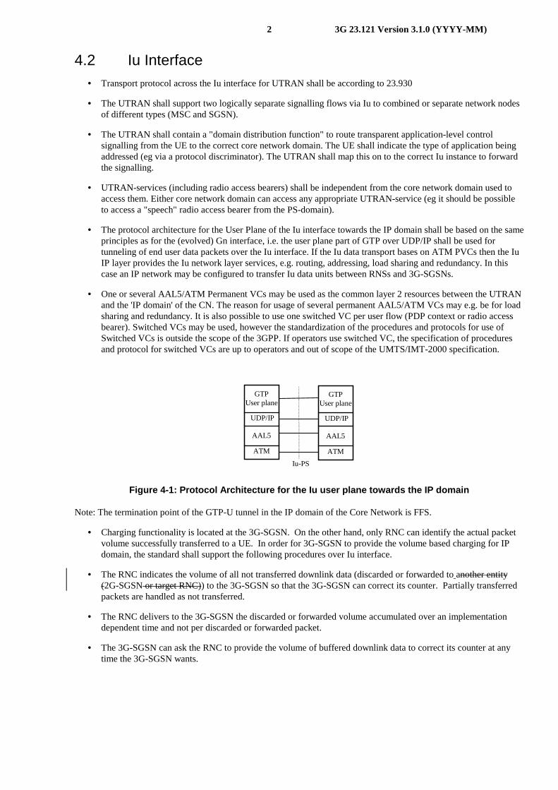
4.2 Iu Interface• Transport protocol across the Iu interface for UTRAN shall be according to 23.930
• The UTRAN shall support two logically separate signalling flows via Iu to combined or separate network nodesof different types (MSC and SGSN).
• The UTRAN shall contain a "domain distribution function" to route transparent application-level controlsignalling from the UE to the correct core network domain. The UE shall indicate the type of application beingaddressed (eg via a protocol discriminator). The UTRAN shall map this on to the correct Iu instance to forwardthe signalling.
• UTRAN-services (including radio access bearers) shall be independent from the core network domain used toaccess them. Either core network domain can access any appropriate UTRAN-service (eg it should be possibleto access a "speech" radio access bearer from the PS-domain).
• The protocol architecture for the User Plane of the Iu interface towards the IP domain shall be based on the sameprinciples as for the (evolved) Gn interface, i.e. the user plane part of GTP over UDP/IP shall be used fortunneling of end user data packets over the Iu interface. If the Iu data transport bases on ATM PVCs then the IuIP layer provides the Iu network layer services, e.g. routing, addressing, load sharing and redundancy. In thiscase an IP network may be configured to transfer Iu data units between RNSs and 3G-SGSNs.
• One or several AAL5/ATM Permanent VCs may be used as the common layer 2 resources between the UTRANand the 'IP domain' of the CN. The reason for usage of several permanent AAL5/ATM VCs may e.g. be for loadsharing and redundancy. It is also possible to use one switched VC per user flow (PDP context or radio accessbearer). Switched VCs may be used, however the standardization of the procedures and protocols for use ofSwitched VCs is outside the scope of the 3GPP. If operators use switched VC, the specification of proceduresand protocol for switched VCs are up to operators and out of scope of the UMTS/IMT-2000 specification.
Iu-PS
AAL5
ATM
UDP/IP
GTPUser plane
AAL5
ATM
UDP/IP
GTPUser plane
Figure 4-1: Protocol Architecture for the Iu user plane towards the IP domain
Note: The termination point of the GTP-U tunnel in the IP domain of the Core Network is FFS.
• Charging functionality is located at the 3G-SGSN. On the other hand, only RNC can identify the actual packetvolume successfully transferred to a UE. In order for 3G-SGSN to provide the volume based charging for IPdomain, the standard shall support the following procedures over Iu interface.
• The RNC indicates the volume of all not transferred downlink data (discarded or forwarded to another entity(2G-SGSN or target RNC)) to the 3G-SGSN so that the 3G-SGSN can correct its counter. Partially transferredpackets are handled as not transferred.
• The RNC delivers to the 3G-SGSN the discarded or forwarded volume accumulated over an implementationdependent time and not per discarded or forwarded packet.
• The 3G-SGSN can ask the RNC to provide the volume of buffered downlink data to correct its counter at anytime the 3G-SGSN wants.

3GPP_TSG_WG2 Meeting #10 Document S299D31Abiko, Japan, 29 Nov. – 3 Dec. 1999 e.g. for 3GPP use the format TP-99xxx
or for SMG, use the format P-99-xxx
CHANGE REQUEST Please see embedded help file at the bottom of thispage for instructions on how to fill in this form correctly.
Current Version: 3.1.023.121 CR 051GSM (AA.BB) or 3G (AA.BBB) specification number ↑ ↑ CR number as allocated by MCC support team
For submission to: SA# for approval X strategic (for SMGlist expected approval meeting # here ↑ for information non-strategic use only)
Form: CR cover sheet, version 2 for 3GPP and SMG The latest version of this form is available from: ftp://ftp.3gpp.org/Information/CR-Form-v2.doc
Proposed change affects: (U)SIM ME X UTRAN / Radio Core Network X(at least one should be marked with an X)
Source: Telia, Telenor, Nokia Date: 99/11/28
Subject: Mobile IP
Work item: “Combined GSM and Mobile IP mobility handling in UMTS IP CN”, “GPRS Mobile IPinterworking”
Category: F Correction Release: Phase 2A Corresponds to a correction in an earlier release Release 96
(only one category B Addition of feature X Release 97shall be marked C Functional modification of feature Release 98with an X) D Editorial modification Release 99 X
Release 00
Reason forchange:
The definition of the APN has been enlarged in 23.060 to also include external PDNaddress allocation. This CR aligns the chapter in 23.121 on Mobile IP with thisenlargement.
Clauses affected: 4.10
Other specs Other 3G core specifications → List of CRs:affected: Other GSM core specifications → List of CRs:
MS test specifications → List of CRs:BSS test specifications → List of CRs:O&M specifications → List of CRs:
Othercomments:
The approved CR 025 to 23.060 at the Bonn meeting triggers this CR.
help.doc
<--------- double-click here for help and instructions on how to create a CR.

2 3G aa.bbb Version x.y.z (YYYY-MM)
4.10 Mobile IP for UMTS/GPRS End Users
4.10.1 Mobile IP for UMTS/GPRS End Users
A single generic mobility handling mechanism that allows roaming between all types of access networks would allowthe user to conveniently move between fixed and mobile networks, between public and private as well as betweenPLMN’s with different access technologies. The ongoing work in IETF Mobile IP working group [13] is targetedtowards such a mechanism1 and a set of standards are planned to be finalised during 1999. Thus, it is important to offerMobile IP also to UMTS and GPRS users to allow them to roam to and from other access technologies while keepingongoing data sessions, e.g. TCP or UDP. A typical UMTS network supporting Mobile IP is shown in Figure 4-46.
Figure 4-46. Core network architecture with GPRS MM within the PLMN’s and Mobile IP MM betweendifferent types of systems.
As IP addresses in IPv4 are scarce, it has to be assumed that Mobile IPv4 preferably will be used with the ForeignAgent (FA) care-of addresses [10]. Compared to using co-located care-of addresses, FA care-of addresses does not onlyconserve IP addresses, it is also more efficient over the radio interface. We assume here that the MS keeps the samecare-of address as long as the PDP context is activated, i.e. does not change GGSN/FA during a UMTS/GPRS session.It is further assumed that PDP type “IP” is used. It is, however, likely that PDP type” PPP” also could be used.Roaming between PLMN’s can be realized with GPRS roaming or Mobile IP.
To offer Mobile IP with FA care-of addresses over the UMTS/GPRS network, some requirements need to be fulfilled.Some of these will cause changes to the current GPRS standards.
1 Note that in this text, Mobile IP is used in a wide sense. It refers to [RFC200210] and the RFC’s planed to be finalized this year.
Iu
CN
UTRAN
HA
UTRAN
RNS
RNS
RNS
IP network
HLRetc.
Iur
filter Internet
MAP
HA
HA
R
Gp
SGSN
GGSN
GGSNFASGSN
PLMNbackbone
GGSN
SGSN
BG
BG Border GatewayR RouterHA Home AgentFA Foreign Agent
FA
FA

3 3G aa.bbb Version x.y.z (YYYY-MM)
A signalling scheme, shown in figure 4-47, is described below. The PPP set-up and the UMTS/GPRS attach proceduresand “GGSN-Initiated PDP Context modification procedure” have been omitted for clarity.
Figure 4-47. PDP Context activation with Mobile IP registration (the PPP set-up and UMTS/GPRSattach procedures not included)
1. The AT command carries parameters that the MT needs to request the PDP Context Activation. The importantparameter here, is the APN (Access Point Name), see section A below. The AT command is followed by a set-up of thePPP connection between the MT and the TE, which are not included in the figure.
2. The MT sends the “Activate PDP Context Request” to the SGSN. The message includes various parameters of whichthe “APN” (Access Point Name) and the “Requested PDP Address” are of interest here. The APN, which is discussedin detail below, points at a requested GGSN. The MS may use APN to select a reference point to a certain externalnetwork and/or to select a service. APN is a logical name referring to the external packet data network and/or to aservice that the subscriber wishes to connect to. The “Requested PDP Address” should be omitted for all MS’s usingMobile IP. This is done irrespective of if the MT has a permanently assigned Mobile IP address from its Mobile IPhome network, a previously assigned dynamic home address from its Mobile IP home network or if it wishes theMobile IP home network to allocate a “new” dynamic home address.
A. The SGSN will base the choice of GGSN is based on the APN that is given by the MS.
The APN consists of two parts: the Network ID and the Operator ID. If no APN is given and PDP type is “IP”, theSGSN chooses a suitable GGSN according to operator’s configuration of the SGSN. Similarly, a Network ID of theformat vvv (one label, no dots) can be used to specify any GGSN with a specific service (vvv), e.g. Internet access,gateway for voice over IP, Mobile IP FA. If the SGSN is not configured to identify the requested service it may try witha DNS interrogation for vvv.current-operator.current-country.gprs or, if that is not successful, with vvv.home-operator.home-country.gprs, where the home parameters are taken from the subscription data.
5. Activate PDPContext Accept
(no PDP address)
4. Create PDPContext Response(no PDP address)
2. Activate PDP Context Request
( APN=MIPv4FA )
IPv4 - Registration UMTS/GPRS + MIP , FA care-of address
TE MT HomeNetwork
SGSN GGSN/FA
3. Create PDPContext Request
( APN=MIPv4FA )
6. Agent Advertisement
7. MIP Registration Request
9. MIP Registration Reply10. MIP Registration Reply
1. AT Command (APN)
8. MIP Registration Request
A. Select suitable GGSN

4 3G aa.bbb Version x.y.z (YYYY-MM)
3. The SGSN requests the selected GGSN to set up a PDP Context for the MS. The PDP address and APN fields arethe same as in the “Activate PDP Context Request” message.
4. A Create PDP Context Response is sent from the GGSN/FA to the SGSN. If the creation of PDP Context wassuccessful, some parameters will be returned to the SGSN, if not, error code will be returned. For Mobile IP users, thePDP address should be omitted. If the GGSN has been configured by the operator to use a Foreign Agent for therequested APN, the PDP adress returned by the GGSN shall be set to 0.0.0.0. indicating that the PDP adress shall benegotiated by the MS with a Home Agent after the PDP context activation procedure.
5. The Activate PDP Context Accept message is sent by the SGSN to the MS and contains similar information as theCreate PDP Context Response message. The PDP address should be omitted.
6. The Agent Advertisement [10] is an ICMP (Internet Control Message Protocol) Router Advertisement message witha mobility agent advertisement extension. The latter part contains parameters of the FA that the mobile node needs,among those are one or more care-of addresses that the FA offers. This message should be sent, in the UMTS/GPRSuser plane, as an IP limited broadcast message, i.e. destination address 255.255.255.255, however only on the TID forthe newly arrived MS to avoid broadcast over the radio interface.
7. The Mobile IP Registration Request is sent from the mobile node to the GGSN/FA across the GPRS/UMTSbackbone as user traffic. The mobile node includes its (permanent) home address as a parameter [10]. Alternatively, itcan request a temporary address assigned by the home network by including the Network Access Identifier (NAI) in aMobile-Node-NAI Extension [12][11].
8. The FA forwards the Mobile IP Registration Request to the home network of the mobile node, where it get processedby a Home Agent (HA). Meanwhile, the GGSN/FA needs to store the home address of the mobile node or the NAI andthe local link address of the MS, i.e. the TID (GPRS Tunnel ID).
9. 9. The Registration Reply is sent from the home network to the FA, which extracts the information it needs (e.g.the home address of the mobile node if allocated by the home network).
10. The FAand forwards the message to the mobile node in the UMTS/GPRS user plane. As the FA/GGSN knows theTID and the NAI or home address, it can pass it on to the correct MS. A home adress of the MS allocated by thehome network is sent to the SGSN by means of the “GGSN-Initiated PDP Context modification procedure”described in [23.060]

TSG SA WG2 #10 Document S2-99E0629.11.-3.12. Abiko, Japan e.g. for 3GPP use the format TP-99xxx
or for SMG, use the format P-99-xxx
CHANGE REQUEST Please see embedded help file at the bottom of thispage for instructions on how to fill in this form correctly.
Current Version: 3.1.023.121 CR 052GSM (AA.BB) or 3G (AA.BBB) specification number ↑ ↑ CR number as allocated by MCC support team
For submission to: TSG SA for approval X strategic (for SMGlist expected approval meeting # here ↑ for information non-strategic X use only)
Form: CR cover sheet, version 2 for 3GPP and SMG The latest version of this form is available from: ftp://ftp.3gpp.org/Information/CR-Form-v2.doc
Proposed change affects: (U)SIM ME UTRAN / Radio Core Network X(at least one should be marked with an X)
Source: Siemens AG Date: 29 Nov. 1999
Subject: Termination point of the GTP-U tunnel
Work item: Iu interface
Category: F Correction X Release: Phase 2A Corresponds to a correction in an earlier release Release 96
(only one category B Addition of feature Release 97shall be marked C Functional modification of feature Release 98with an X) D Editorial modification Release 99 X
Release 00
Reason forchange:
Deletion of the note "The termination point of the GTP-U tunnel in the IP domain of theCore Network is FFS." as the termination of the GTP-U tunnel over the Iu interface isclarified and is the 3G-SGSN
Clauses affected: 4.2.
Other specs Other 3G core specifications → List of CRs:affected: Other GSM core specifications → List of CRs:
MS test specifications → List of CRs:BSS test specifications → List of CRs:O&M specifications → List of CRs:
Othercomments:

4.2 Iu Interface• Transport protocol across the Iu interface for UTRAN shall be according to 23.930
• The UTRAN shall support two logically separate signalling flows via Iu to combined or separate network nodesof different types (MSC and SGSN).
• The UTRAN shall contain a "domain distribution function" to route transparent application-level controlsignalling from the UE to the correct core network domain. The UE shall indicate the type of application beingaddressed (eg via a protocol discriminator). The UTRAN shall map this on to the correct Iu instance to forwardthe signalling.
• UTRAN-services (including radio access bearers) shall be independent from the core network domain used toaccess them. Either core network domain can access any appropriate UTRAN-service (eg it should be possibleto access a "speech" radio access bearer from the PS-domain).
• The protocol architecture for the User Plane of the Iu interface towards the IP domain shall be based on the sameprinciples as for the (evolved) Gn interface, i.e. the user plane part of GTP over UDP/IP shall be used fortunneling of end user data packets over the Iu interface. If the Iu data transport bases on ATM PVCs then the IuIP layer provides the Iu network layer services, e.g. routing, addressing, load sharing and redundancy. In thiscase an IP network may be configured to transfer Iu data units between RNSs and 3G-SGSNs.
• One or several AAL5/ATM Permanent VCs may be used as the common layer 2 resources between the UTRANand the 'IP domain' of the CN. The reason for usage of several permanent AAL5/ATM VCs may e.g. be for loadsharing and redundancy. It is also possible to use one switched VC per user flow (PDP context or radio accessbearer). Switched VCs may be used, however the standardization of the procedures and protocols for use ofSwitched VCs is outside the scope of the 3GPP. If operators use switched VC, the specification of proceduresand protocol for switched VCs are up to operators and out of scope of the UMTS/IMT-2000 specification.
Iu-PS
AAL5
ATM
UDP/IP
GTPUser plane
AAL5
ATM
UDP/IP
GTPUser plane
Figure 4-1: Protocol Architecture for the Iu user plane towards the IP domain
Note: The termination point of the GTP-U tunnel in the IP domain of the Core Network is FFS.
• Charging functionality is located at the 3G-SGSN. On the other hand, only RNC can identify the actual packetvolume successfully transferred to a UE. In order for 3G-SGSN to provide the volume based charging for IPdomain, the standard shall support the following procedures over Iu interface.
• The RNC indicates the volume of all not transferred downlink data (discarded or forwarded toanother entity(2G-SGSN or target RNC)) to the 3G-SGSN so that the 3G-SGSN can correct its counter. Partially transferredpackets are handled as not transferred.
• The RNC delivers to the 3G-SGSN the discarded or forwarded volume accumulated over an implementationdependent time and not per discarded or forwarded packet.
• The 3G-SGSN can ask the RNC to provide the volume of buffered downlink data to correct its counter at anytime the 3G-SGSN wants.