tsbc bac 061121 a06q0188
TRANSCRIPT
8/7/2019 TSBC BAC 061121 A06Q0188
http://slidepdf.com/reader/full/tsbc-bac-061121-a06q0188 1/17
AVIATION INVESTIGATION REPORT
A06Q0188
LOW FUEL EMERGENCY
AIR CANADA JAZZ
BOMBARDIER CL-600-2B19 C-GJZF
FORT ST. JOHN, BRITISH COLUMBIA
21 NOVEMBER 2006
8/7/2019 TSBC BAC 061121 A06Q0188
http://slidepdf.com/reader/full/tsbc-bac-061121-a06q0188 2/17
The Transportation Safety Board of Canada (TSB) investigated this occurrence for the purposeof advancing transportation safety. It is not the function of the Board to assign fault ordetermine civil or criminal liability.
Aviation Investigation Report Low Fuel Emergency Air Canada JazzBombardier CL-600-2B19 C-GJZF
Fort St. John, British Columbia21 November 2006 Report Number A06Q0188
Summary
On 21 November 2006, an Air Canada Jazz CL-600-2B19 (registration C-GJZF, serialnumber 7545) with 49 passengers and 3 crew members on board was being operated as ascheduled flight from Vancouver, British Columbia, to Prince George, British Columbia. Atabout 1514 Pacific standard time, the aircraft was cleared for a non-precision approach onRunway 33 at Prince George Airport. While established on final approach, the flight crew wasinformed of a special weather observation, indicating conditions below the published minima.The flight crew continued the approach and set the flaps at 45 degrees. On reaching the finalapproach fix, the flight crew conducted a missed approach and noted that the flaps remainedjammed at 45 degrees. The flight crew members diverted to their alternate airport, Grande Prairie, Alberta. The aircraftwas cleared to maintain 15 000 feet and vectored toward Grande Prairie. At 1537, the flight crewrequested radar vectors to Fort St. John, British Columbia, about 155 miles away, and declaredan emergency due to a low fuel prediction at destination. At 1616, the aircraft landed withoutfurther problem at Fort St. John with about 500 pounds of fuel remaining, equivalent to lessthan 10 minutes of flight. There were no injuries. Ce rapport est également disponible en français.

8/7/2019 TSBC BAC 061121 A06Q0188
http://slidepdf.com/reader/full/tsbc-bac-061121-a06q0188 3/17
- 2 -
Other Factual Information Records indicate that the flight crew members were certified and qualified in accordance withexisting regulations and approved procedures.
At about 1436 Pacific standard time,1
Air Canada Jazz CL-600-2B19, operated as Flight 8205,departed Vancouver for a 47-minute flight to Prince George. According to the operational flightplan (OFP), the minimum fuel requirement at take-off was 5738 pounds and the calculated fuelburn to destination was 2405 pounds. According to the flight data recorder, the take-off roll wasinitiated with 6100 pounds of fuel on board, which exceeded the OFP minimum fuelrequirements by 362 pounds. Based on the terminal area forecast (TAF) issued at 0942, the weather conditions to be expectedat the time of arrival at destination were as follows: ceiling 2000 feet above ground level (agl),visibility 3 statute miles in light snow and wind from 010° true (T) at 15 knots gusting to25 knots. While en route, two new TAFs were issued for Prince George, one at 1508 and one at1519. Both indicated a deterioration of weather conditions with visibility forecast to be as low as¼ mile in heavy snow and a vertical visibility of 200 feet expected temporarily between 1500and 1700. The flight crew was not aware of these new TAFs. However, at 1508, the flight crewreceived the 1500 aviation routine weather report (METAR),2 which was as follows: wind 030ºTat 23 knots gusting to 29 knots, visibility ⅝ statute mile with light snow showers and driftingsnow, sky obscured at 900 feet, and temperature -5ºC. The runway surface condition was 50 per cent bare and dry and 50 per cent covered withdrifting snow. The runway friction index was 0.46. The flight crew communicated with thecompany to discuss the action plan in the case of a missed approach and to see what would bethe fuel required to go back to Vancouver instead of the planned alternate. A decision wasmade to try an approach and then hold as long as possible before going to the planned alternate
airport. At 1514, the flight was cleared for a localizer back course, VOR DME 1 (very high frequencyomnidirectional radio range distance measuring equipment) approach to Runway 33. Thepublished landing minimum was 405 feet agl and a visibility of 1 ¼ miles. The flight crewplanned for a stabilized constant descent angle (SCDA) approach. The SCDA consists of astabilized approach to achieve a constant rate of descent. The criteria are as follows: a descentangle of approximately three degrees; stable airspeed, power setting, and attitude; and theaircraft configured for landing (flaps set at 45°) one to two miles from the final approach fix(FAF).
At about 23 miles from the threshold, the tower informed the flight crew that the ceiling was800 feet with a visibility of ½ mile. The opposite landing runway (Runway 15) is served by arunway visual range (RVR), which indicated a visual range of 5000 feet. At 12 miles on final, the
1 All times are Pacific standard time (Coordinated Universal Time minus eight hours). 2 METAR is the name of the international meteorological code for an aviation routine weather
report normally taken and disseminated on the hour.
8/7/2019 TSBC BAC 061121 A06Q0188
http://slidepdf.com/reader/full/tsbc-bac-061121-a06q0188 4/17
- 3 -
flight crew was informed of a special weather report indicating a ceiling at 500 feet and avisibility of ⅜mile in snow and drifting snow. The flight crew continued the approach, and atabout eight miles on final, the flaps were extended to 20°, the landing gear selected down, andthen the flight spoilers deployed. At 3.3 miles from the threshold, less than ½ mile from theFAF, the flaps were selected to 45° and the flight spoilers were retracted.
Based on the rapidly decreasing visibility, the flight crew carried out a missed approach onreaching the FAF. At that time, the fuel remaining on board was 4000 pounds, which exceededthe OFP minimum fuel requirements to proceed to the alternate airport by 1312 pounds. As theflaps were selected to 8° and the landing gear was retracted, the “FLAP FAIL” messageappeared on the engine indication and crew alerting system (EICAS). The aircraft initial climbrate was approximately 1600 feet per minute but gradually decreased with altitude untilreaching 10 000 feet above sea level (asl), the initial cleared altitude. The flight was later clearedto maintain 15 000 feet asl as its final cruising altitude. According to the quick reference handbook (QRH), if the flap failure occurs at greater than 5°,as in this occurrence, the aircraft should land at the nearest suitable airport. If the flap failure
occurs at 45°, no further action is required before landing. This is based on the fact that thelanding will be carried out as usual. The QRH does not take into consideration the possibility ofa missed approach and the impact it would have on the aircraft performance for obstacleclearance or fuel consumption. As well, it does not provide an alternative solution to theproblem. In such a case, flight crews are expected to use their good judgement. This flight crewcycled the flap electronic control unit (FECU) circuit breakers, but this did not clear the fault.The flap handle lever was then selected to different detent positions and the FECU circuitbreakers were cycled again. The fault did not clear. The flight crew members requested a diversion to their planned alternate airport,Grande Prairie, and subsequently requested to go to Fort St. John, which was slightly closer. En
route, the flight crew attempted to find out what would be the best altitude and speed toprovide the best fuel range. However, no such data were available. The flight managementsystem (FMS) was used to determine the fuel prediction at Fort St. John. At 1537, the flight crewdeclared an emergency due to the low fuel prediction. At that time, the fuel flow wasapproximately 4100 pounds per hour, significantly higher than the fuel flow in cruise fromVancouver to Prince George, which was about 2700 pounds per hour. At 1616, the aircraftlanded at Fort St. John without further problem with about 500 pounds of fuel remaining,equivalent to less than 10 minutes of flight.
Certification Basis
The Canadair Regional Jet (CRJ) 100/200 aircraft model CL-600-2B19 was type-certificated as atransport category aircraft in Canada on 31 July 1992, under Part 25 of the Federal AviationRegulations (FARs), including amendments 25-1 through 25-62, with some exceptions/additionslisted in the type certificate data sheet number A-131. The type certificate data sheet prescribesthe conditions and limitations under which the product for which the type certificate wasgranted meets the airworthiness standards required by the Canadian Aviation Regulations (CARs). The type certificate holder for the CRJ 100/200 aircraft model CL-600-2B19 isBombardier Inc.
8/7/2019 TSBC BAC 061121 A06Q0188
http://slidepdf.com/reader/full/tsbc-bac-061121-a06q0188 5/17
- 4 -
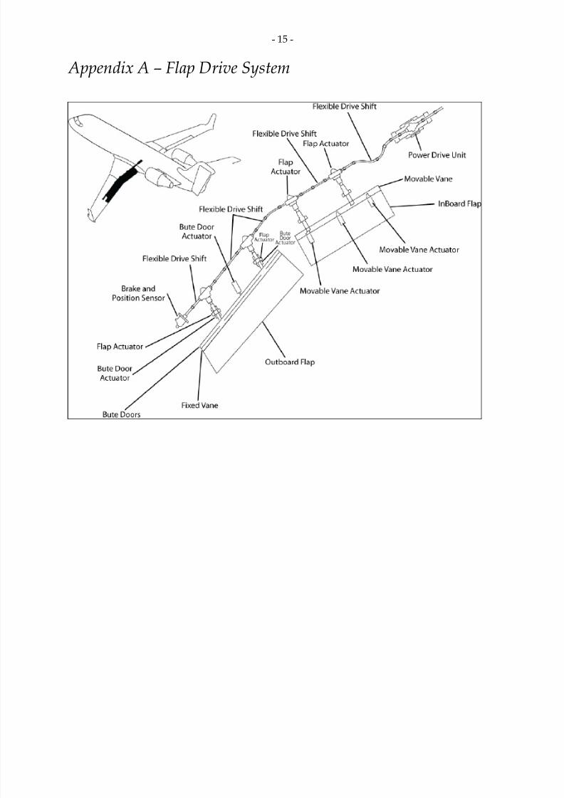
Description of Flap System The flap control surface system consists of one inboard and one outboard double-slotted flap(see Appendix A) installed on the trailing edge of each wing. The two inboard flap panels movethrough a range of 0° to 45°, and the two outboard flap panels move through a range of 0° to40°. Each inboard flap contains one movable leading edge vane and three movable vane
actuators. Each outboard flap contains one bent-up trailing edge (BUTE) door and three BUTEdoor actuators. The flap selection commands are made by manually positioning the flap control lever into oneof the five detents on the flap control lever assembly located on the centre pedestal. Thesecommands go to the FECU, which operates the power drive unit (PDU) and the brakepositioning sensing unit (BPSU). The FECU energizes the PDU, which drives the flaps to theselected position through the flexible drive shafts and the flap actuators. The FECU also controlsthe release of the brakes in the PDU and the BPSUs. The BPSU brakes are a backup to the PDUbrakes. The BPSU position sensors supply flap position information to the FECU, which permitthe FECU to control and monitor the position of the flap system. The FECU has 14 types of fault
detectors and five signal interfaces between the FECU and the digital air data computers. Themost common fault detectors are asymmetry, overspeed, underspeed, and motor currentfailures. The flap actuating mechanism system consists of 10 flexible drive shafts, 4 inboard flapactuators, and 4 outboard flap actuators. The flexible drive shafts are located aft of the wing rearspar. They have different lengths and diameters. There are five different types of flexible driveshafts (two of each type). They are designated number 1 (inboard most) to number 5 (outboardmost). Each flexible drive shaft comprises an outer tubing and a removable core. The core ismade of steel impregnated with grease. The outer tubing is made from continuous, extruded,smooth bore, graphite/Teflon tubing with an outer layer of braided corrosion-resistant steel.
The flap position transmitters are operated by control rods attached to the hinge arms of theinboard flaps. They supply flap position signals to the EICAS for the display of flap positioninformation to the flight crew and to the stall-protection system computers. The skew detection system (SDS) is made up of a skew detection unit (SDU), found in theavionics compartment, and four proximity sensors and target assemblies. The proximity sensorsand target assemblies are located on the outboard flap panel actuators. When the flaps are inmotion, the SDU receives the four proximity inputs from the sensors and produces a digitalpulse. This digital pulse is used to compare the turn rate of each of the outboard flap actuatorball screws, which allows the SDU to monitor for skew conditions (an outboard flap panel twist
greater than two degrees). Command signals from the flap control lever are sent to both channels of the FECU. Eachchannel controls one of the two PDU motors and has two failure detectors. Each of thesedetectors receives signals that show system faults. The output of each failure detector in thechannel is a fail signal. This fail signal causes the disconnect relay to operate, the associatedmotor to stop, and both brakes to come on. The fail signal also stops the command signals that
8/7/2019 TSBC BAC 061121 A06Q0188
http://slidepdf.com/reader/full/tsbc-bac-061121-a06q0188 6/17
- 5 -
let the motor operate in the extended or retracted direction. The second motor is stopped in thesame way by the other channel. The power supply and the motor and brake control circuits arecommon to both subsystems in each channel.
Flap Actuators There are eight flap actuators installed on the wing trailing edge, two actuators to each flappanel. There are five types of flap actuators; the four that operate the inboard flaps areinterchangeable. Each of the outboard flap actuators is different. The actuators need 801 driveshaft turns for a complete full stroke, corresponding to 0° to 45°. The flap actuators are of the linear ball screw type gimbals mounted to the wing rear spar andthe flap hinges. The ball screw circuits are dual for redundancy. They also incorporate icescrapers and wipers. The main housing contains the drive gearset, which is lubricated bysynthetic oil bath. Each flap actuator has a ball nut and screw assembly with single-stage helicalgearing, lubricated by grease that is applied via a grease fitting located on the nut. A torquelimiter, which is used as a load-limiting device, is comprised of a spring back and a brake
assembly mechanism and is contained within the main housing inside dry cavities on eitherside of the gearset. The torque limiter mechanism dry cavities are segregated from the oil-filledgearbox by Teflon-based dynamic seals. The torque limiter has a series of alternative friction plates. Half of these are splined to the inputshaft and half to the stationary housing. Excess torque through the gear mesh causes the springpack to close. This lets the input shaft and the friction plate move. This also causes a pressure onthe friction plate stack, which causes brake torque, keeping the output force of the actuator to alimit. The flexible drive shafts transmit torque from the PDU to each flap actuator and to the BPSU.
Rotation of the input drive causes the ball screw shaft to turn. This rotation causes the ball nutto move along the shaft in the extend or retract direction.
Airworthiness Directives On 06 July 1998, Transport Canada (TC) issued Airworthiness Directive (AD) CF1998-14. At thetime of the occurrence, the AD was at revision number 4 (CF1998-14R4); the effective date was25 June 2004, with a completion date of 31 December 2006. All CRJ CL-600-2B19 from serialnumber 7003 to serial number 7903 were affected by this AD. This revision introduced a newflap actuator and SDS for the outboard flaps. The AD is divided into six parts:
Part I consists of an Air Operator action and proposes an amendment to the aircraftflight manual (TR CRJ/171).
Part II is a maintenance-related action in which a visual check of each flap isconducted for evidence of twisting, skewing or abnormal deformation, and then tointerrogate the FECU log menu for fault isolation.
8/7/2019 TSBC BAC 061121 A06Q0188
http://slidepdf.com/reader/full/tsbc-bac-061121-a06q0188 7/17
- 6 -
Part III is a modification action to be completed within 450 hours after 25 June 1999.This required the installation of new airspeed limitation placards and decals withreduced maximum flap extended speeds and a second placard requesting a visualinspection of the flaps before departure. Both decals must be installed in the cockpit.
Part IV is a flap actuator health check inspection.
Part V is the installation of new flap actuators within 12 months of the effective date
of this revision.
Part VI is the installation of an SDS by 31 December 2006. Compliance with therequirements of Part VI of this directive provides terminating action to allrequirements of this directive.
The Federal Aviation Administration (FAA) issued AD 98-20-01 on 02 October 1998. At the timeof the occurrence, this AD had been superseded by AD 2006-12-21 (effective 21 July 2006). AllCRJ CL-600-2B19 serial number 7003 to serial number 7903 are also affected by this AD. This
AD resulted from a number of cases of flap system failure that resulted in a twisted outboardflap panel. AD 2006-12-21 requires the following:
installation of new flap actuators within 12 months from the effective date of this AD(by July 2007);
installation of the SDS and the air data computer within 30 months from the effectivedate of this AD (January 2009);
new airspeed limitation placards;
a revision of the aircraft flight manual (AFM) to include revised maximum allowablespeeds for flight with flaps extended; and
a new SDS/crosswind-related limitation for take-off flap selection.
Difficulty Report and Flap Occurrences The issue of flap failure on CL-600-2B19 aircraft has been known for many years. A review ofthe Service Difficulty Report (SDR) system in Canada and the United States from 01 January2006 to 01 January 2007 indicated 751 flap problem occurrences. More than 50 per cent (381) ofthe occurrences involved Bombardier CL-600-2B19 series aircraft. Of these 381 events,
209 system resets were carried out without being able to identify any fault. On 20 occasions, thecrew received a flap fail message on the EICAS while the aircraft was established at cruisingaltitude. A flap occurrence is not in itself a reportable occurrence under the TSB regulations, andtherefore the TSB database may not include all failures of this type. A review of the TSBdatabase of flap events since 2005 indicates an increasing number of reported flap failuresexperienced by CRJ aircraft. There were 20 reported occurrences in 2005 and 28 in 2006. In
8/7/2019 TSBC BAC 061121 A06Q0188
http://slidepdf.com/reader/full/tsbc-bac-061121-a06q0188 8/17
- 7 -
January 2007, the TSB database indicates 31 events of flap failure, suggesting that the frequencyof CRJ flap failures is increasing. These numbers only represent occurrences in Canada andinclude both Canadian and foreign operators.
Maintenance Related to the Flap Actuators
The current maintenance program for the actuators includes a backlash check3 every1000 hours, a functional check4 of the actuators after 14 000 cycles, and an overhaul at20 000 cycles. The life cycle limit has been established at 33 333 cycles. Records of maintenancerepairs from Air Canada Technical Services (ACTS) indicates that actuators can fail at as low as2657 cycles, long before any specific maintenance action takes place. The ACTS facility in Montréal, Quebec, conducted a teardown of eight actuators from a CRJaircraft that had experienced a flap failure on 30 January 2007. Of the eight actuators, four ofthem failed the cold temperature test at -51°C and showed the presence of contamination. Thesetests detect elevated drive line torque due to moisture, oil, or corrosion. The most commonreason for failure is oil in the torque limiter brake cavity, which results in elevated input torque
to rotate the pinion gear. Oil viscosity increases under cold temperatures to a point where oilshear forces between the brake plates increase to cause high input torque. The quality of thesealant on actuator mating surfaces was also questionable as it could often be removed by hand,thereby permitting water ingress.
Water Ingress in the Flap System Cold weather flap jams can be due to lubrication issues (such as excessive grease on flexibledrive shafts), but are more commonly an indication of water in the flap system components.When water gets into the flap system, it does so primarily through the B-nut couplings, at theends of each flexible drive shaft. If there is no watertight seal at the flexible drive shaftcouplings, water can enter the flexible drive shafts through capillary action, assisted by themovement of air in and out of the shafts due to pressure changes. When the water freezes, it can cause high running torque or freeze the drive shaft completely.The components connected to the flexible drive shafts in the wing, the flap actuators, and theBPSUs also have air cavities. Although there are seals in the input shafts of these components,deterioration and wear of these seals can allow water that is in the flexible drive shaft to enterthe actuator or BPSU. Water ingress to the brake cases of flap actuators may occur due to the external bead seal for theseam of the actuator connector cap being compromised. The connector cap is the threaded
fitting on each side of the actuator gearbox case to which the flexible drive shaft connects. Waterin the actuators themselves can be confirmed by the low temperature torque check. In
3 The backlash check of the flap actuator, done at the actuator on the aircraft, measures for toomuch wear in the actuator gearbox and ball screw.
4 A quantitative check to determine if one or more functions of an item perform within specified
limits. This test includes removal and testing of the actuator in the shop.
8/7/2019 TSBC BAC 061121 A06Q0188
http://slidepdf.com/reader/full/tsbc-bac-061121-a06q0188 9/17
- 8 -
October 2006, Bombardier issued a modification to replace the Teflon spring seal for the flexibledrive shaft with a new steel washer. These new washers were not immediately available andAir Canada Jazz had to submit a request to use an alternate type of washer. Bombardier hasissued service bulletins and service letters to review all known issues related to contaminationin the flap system.
Flexible drive shafts have always been a contributing factor for water to ingress the system.Careful attention must be exercised when handling, installing, and removing flexible driveshafts to prevent damage. Most problems encountered with flexible drive shafts are related tobending radius limits, contamination through wires and couplers, and excess lubrication, whichcan cause high, cold-temperature torque. The flap actuators are manufactured by Eaton Aerospace. In the revised Eaton Aerospacecomponent maintenance manual (CMM), published in January 2007, the type of grease waschanged from MIL-PRF-23827 or CSM1171 to MIL-PRF-23827C, Type II (Aeroshell 17).Previously, operators were using either type I or type II grease, with the mention that they notbe mixed together. Tests during the investigation revealed that the type of grease used for ball
nut lubrication could have been a contributing factor to flap system failures.
Low-Temperature Torque Check
According to the Eaton Aerospace CMM, a low-temperature torque check is performed byplacing the actuator in a cold chamber until the temperature stabilizes at -40°C (-40°F) ± 2.5°C.Using a torque wrench and an input adapter, the technician rotates the input shaft clockwise fortwo complete revolutions at a speed of approximately one revolution per 2.0 seconds. Theacceptable cold temperature breakout torque should not exceed 15.0 inch-pounds. Themanufacturer has also established a temperature range limitation of -40°C to 75°C.
In the Bombardier aircraft maintenance manual (AMM), it is stated that the low-temperaturetorque check is done when it is suspected that there is water in the actuator. Flap actuators mustbe removed from the aircraft to do a low-temperature torque check. The test is done at atemperature of -51°C (-60°F); the maximum input breakout torque has been established at18 inch-pounds. The AMM also states that, if the measured torque is more than the value in thetable for a given temperature, the actuator is unserviceable. A review of the Bombardier AMMand Eaton Aerospace CMM is required to reconcile the differences with respect to temperatureand torque values for the low-temperature torque check.
CRJ 200 C-GJZF Maintenance on Flap System
Maintenance records following the 21 November 2006 incident show that a noticeable amountof water was extracted from the actuators’ ball nuts during the greasing process. Following this incident, C-GJZF was involved in four other flap failure eventsone inNovember 2006, two in December 2006, and one on 10 January 2007. A review of the aircraftmaintenance records showed that Air Canada Jazz maintenance personnel were dealing with avarying array of symptoms. During the troubleshooting process, they replaced the PDU fourtimes, the FECU three times, the left BPSU four times, the right BPSU two times, the flap handle
8/7/2019 TSBC BAC 061121 A06Q0188
http://slidepdf.com/reader/full/tsbc-bac-061121-a06q0188 10/17
- 9 -
one time, flexible drive number 5 one time, and three actuators on the last maintenance actionrelated to the flap system. After 10 January 2007, there were no other reported flap failureincidents with this aircraft. When water is suspected in the flap system, the fault isolation manual (FIM) directs themechanic to specifically do a torque check of the flap drive system and not the low-temperature
torque check as specified in the AMM. The torque check is carried out at ambient temperaturesvarying from 15°C to 35°C. The investigation revealed that the detection of faulty actuators ispossible using a low-temperature torque check. The low-temperature torque check was notperformed following detection of water in the actuators on 22 November 2006 as was requiredby the AMM. Actuators that were removed on 10 January 2007 were tested at the ACTS facility in Montréal.The following results were obtained:
Left number 3, part number 853D100-19, serial number 2777 (total time of6965.4 hours), failed the cold test at a temperature of -51°C with 70 inch-pounds.
There was oil in the brake side from an inside seal leaking and minor corrosion wasfound on the shaft.
Right number 1, part number 852D100-11, serial number 2962AB (total time of10953.4 hours and 9367 cycles), failed the input torque at 28 inch-pounds. Themaximum retract torque should be 4 inch-pounds and this unit shows28 inch-pounds. It also failed the extend torque, which should be 10.8 inch-poundsand it was at 36 inch-pounds. The axial play on the ball screw and ball nut was 0.013when the maximum should be 0.005. End play on the ball screw and main housingwas 0.018 when the maximum should be 0.003. It was found to be dangerous tocontinue testing at higher speeds and loads.
Right number 4, part number 854D100-20, serial number 2566, (total time of
6949.4 hours and 6118 cycles), failed the cold test at -51°C with 25 inch-pounds. Theunit was found to have inside seals leaking and an end play at 0.0025 when themaximum should be 0.003.
Resetting or Cycling of Circuit Breakers A circuit breaker must not be reset or cycled unless doing so is consistent with the explicitprocedures specified in the QRH and the AFM. However, resetting or cycling of the circuitbreaker is permitted if, in the judgement of the captain, it is necessary for the safe completion of
the flight. In most flap failure events, FECU circuit breakers were recycled by technical staff on theground, which clears the problem. The manufacturer’s FIM states to perform a bite test of theFECU, and if no faults are present, a reset of the associated circuit breakers will rectify the issue.Aircraft were returned to service without any further maintenance inspection and/ortroubleshooting.
8/7/2019 TSBC BAC 061121 A06Q0188
http://slidepdf.com/reader/full/tsbc-bac-061121-a06q0188 11/17
- 10 -
Analysis When the flight crew left Vancouver, nothing in the available TAF indicated that the weatherconditions at destination would be below the published minima. The weather conditionsreported to the flight crew, once established on final, indicated ceilings above the published
minimum descent altitude (MDA). However, the visibility was below the published landingvisibility. Published landing visibilities are advisory only. They are not limiting and areintended to be used by pilots only to judge the probability of a successful landing. Consideringthe poor visibility, the surface wind, and the runway surface condition, the probability of asuccessful landing was low. When the flight crew received the special weather observation, the aircraft was not yetconfigured for landing. When the flight crew carried out the missed approach and selected theflaps up, the “FLAP FAIL” message was received. The opposite runway was equipped with an instrument landing system (ILS) and could havebeen an option to the flight crew since it provides lower minima. However, considering thesurface wind direction, its velocity and the runway surface conditions, it would have been riskyto try a landing on Runway 15. Furthermore, the fuel on board at the time of the missedapproach was above the minimum diversion fuel requirement by 1312 pounds; therefore, theflight crew diverted the flight to the alternate airport. While in the climb, the flight crew attempted to solve the problem, without success. Withoutcruise performance data available for this flap configuration, the flight crew used the FMS fuelprediction to determine if they could reach Fort St. John. Had the aircraft burned fuel asplanned from Vancouver to Prince George and had it departed Vancouver without the360 pounds of extra fuel, it would have run out of fuel before reaching Fort St. John. However,the crew’s decision to divert to Fort St. John was timely, and reduced the risk of running out of
fuel. The issue of flap failures on the CL-600-2B19 aircraft has been known for many years. Operatorshave implemented a standard of recycling circuit breakers on the ground to deal with theproblem of flap failure. The manufacturer’s FIM also states to perform a bite test of the FECU,and if no faults are present, a reset of the associated circuit breakers will rectify the issue. Thishas been done so regularly by crew and/or maintenance personnel that it has become anacceptable practice throughout the aviation industry. Data provided during the investigation indicate that water ingress into the flap system,combined with cold weather operation, is the leading cause of the flap system failure. In
June 2005, new flap actuators were installed on all Canadian aircraft in accordance withAD CF1998-14R4, Part V. The investigation revealed that the problem of water ingress stillexists, even on these new models of actuators. When contaminants get into the actuatorhousing, this will eventually lead to contamination of the actuator’s moving parts and result inrestrictions to movement. Bombardier has put effort into solving the problem by informingworldwide operators through service letters, service bulletins and other publications.Unfortunately, the problem still exists and the number of reported flap failures in Canada isincreasing.
8/7/2019 TSBC BAC 061121 A06Q0188
http://slidepdf.com/reader/full/tsbc-bac-061121-a06q0188 12/17
- 11 -
The ambient temperature limitation range for actuators has been established at -40°C to 75°C(-40°F to 167°F) by the manufacturer, Eaton Aerospace. During flight, flap actuators areoperated regularly at temperatures lower than -40°C. The Bombardier AMM permits thelow-temperature torque check to be carried out at temperatures as low as -51°C. Theinvestigation was unable to establish consequences of operating these actuators at temperatureslower than the ambient temperature limitation of -40°C.
The investigation revealed that actuators with cycles as low as 2657 cycles had failed because ofcontamination. The maintenance program for the flap actuator system does not require specialinspection for contamination at an established timeframe. In fact, the AMM prescribed alow-temperature torque check only if water ingress is suspected. The currently establishedmaintenance program is not adequate in that it does not detect problems in the actuators at anearly enough stage to prevent flap failure; therefore, a re-analysis of the CRJ flap systemmaintenance program using MSG-35 should be emphasized. Replacement of Teflon spring seals by new steel washers in the flexible drive shaft inOctober 2006 may have reduced and/or stopped the water to ingress the system. However,
contaminated flap actuators already installed on aircraft will continue to deteriorate andeventually lead to a flap failure. In fact, bench checks combined with a low-temperature torquecheck are a more accurate method to identify defective actuators. Aircraft flap actuators thatwere tested in January 2007 did not have the new steel washer modifications because they werenot immediately available. Maintenance records for the 21 November 2006 incident show that a noticeable amount of waterwas extracted from the actuators’ ball nuts during the greasing process. The AMM specifiedthat a low-temperature torque check be accomplished whenever water is suspected in thesystem. The maintenance record review of C-GJZF had shown that a number of parts werereplaced during the process of troubleshooting the flap failures (November 2006 to January
2007). Documented maintenance records clearly demonstrate that Air Canada Jazz maintenanceorganization was dealing with a varying array of symptoms. There is no consistency betweenthe troubleshooting procedure in the FIM and the AMM. Maintenance personnel followed theprescribed troubleshooting technique in their FIM but did not use the AMM following thediscovery of water in the flap actuator system on 22 November 2006. It was only in January 2007that three of the eight actuators were removed and failed the low-temperature torque check atthe ACTS facility. It appears that the replacement of these three actuators resolved the flapfailure problem on C-GJZF. A thorough knowledge of the flap system and consistency in themaintenance documentation would have allowed the maintenance personnel to identify andsolve the problem sooner.
5 Maintenance Steering Group – 3rd task force
8/7/2019 TSBC BAC 061121 A06Q0188
http://slidepdf.com/reader/full/tsbc-bac-061121-a06q0188 13/17
- 12 -
The following TSB Engineering Laboratory report was completed:
LP 114/2006 FDR/CVR Download and Analysis This report is available from the Transportation Safety Board of Canada upon request.
Findings as to Causes and Contributing Factors 1. The maintenance program for Bombardier CL-600-2B19 flap system actuators in place
at the time of the occurrence did not allow for the detection of problems in the flapactuators at an early enough stage to prevent flap failure.
2. The flaps failed at the 45-degree position, increasing drag significantly. The
subsequent increase in fuel consumption required the crew to declare an emergencyand divert to Fort St. John, which was a closer airport, landing with less than10 minutes of fuel remaining.
3. A thorough knowledge of the flap system and consistency in the maintenance
documentation would have allowed the maintenance personnel to identify and solvethe problem sooner.
4. Repetitive flap failures on C-GJZF were the consequence of faulty actuators caused by
contamination such as water.
Findings as to Risk 1. Water ingress into the flap system, combined with cold weather operations, is the
leading cause of flap system failure on CL-600-2B19 aircraft. 2. The quick reference handbook (QRH) does not take into consideration the impact of
flap failures at 45° following a missed approach. Consequently, the flight crews arenot fully aware of the impact it would have on the aircraft climb performance forobstacle clearance or the impact on fuel consumption.
3. There is no cruise performance data available with flaps extended. Therefore, the
flight crew could not determine the optimum altitude and speed to attain the best fueleconomy.
Other Finding 1. The practice of recycling a circuit breaker to rectify a problem has inherent risks;
however, in this occurrence, it was a reasonable action on the part of the crew.
8/7/2019 TSBC BAC 061121 A06Q0188
http://slidepdf.com/reader/full/tsbc-bac-061121-a06q0188 14/17
- 13 -
Safety Action Taken On 01 December 2006, Air Canada Jazz issued Flight Operations Memo 06-257 to its pilotsentitled CRJ Fuel Policy Adjustment. A risk-based assessment was completed and eight airportswere identified to be isolated enough to warrant an extra 30 minutes of fuel contingency when
the forecast weather is less than 1000 feet and the visibility is 3 miles. This memo was effectiveimmediately and is now part of the company fuel policy for flight planning purposes.Air Canada Jazz initiated a conference with Air Canada Technical Services (ACTS),Eaton Aerospace, and Bombardier to discuss the design, operation, and support of the recentflaps and actuator issues. Shortly after, Bombardier announced the formation of a flap workinggroup, including six operators, whose mandate is to work with Eaton Aerospace andBombardier to complete a system redesign to remove the high seasonal failures of the flapsystem. Air Canada Jazz has been an active participant in the flap working group and has assisted in thecreation of the maintenance task currently being applied to the entire fleet via the AirworthinessDirective (AD) and Service Bulletin SB601R27-150. At the beginning of January 2007, Air Canada Jazz formalized a process where any CanadairRegional Jet (CRJ) 100/200 that experienced a flap failure would require senior managementapproval before the aircraft was returned to service. On 14 February 2007, the TSB issued Aviation Safety Advisory A06Q0188-D2-A1 (Potential FuelExhaustion Due to a CL-600-2B19 Flap Failure) to Transport Canada (TC). The Safety Advisorysuggests that Transport Canada may wish to advise other Canadian CL-600-2B19 operators andthose foreign regulatory authorities that administer CL-600-2B19 aircraft of the circumstances ofthis occurrence and the possible impact of flap system failures on fuel management.
As a result of this Safety Advisory, Bombardier Aerospace issued All Operators Message(AOM) 1047, dated 10 March 2007, to alert all operators of this incident and the possible impactof flap system failures on fuel management. TC drafted a document outlining CRJ flap operational issues and considerations. This documentwill be offered to Bombardier for its review and awareness. The document will be transmittedto all affected operators of Canadian-registered aircraft, as well as foreign Civil AviationAuthorities, by way of a Service Difficulty Advisory. On 16 February 2007, the TSB issued Board Concern A06Q0188-D1-C1 (Bombardier CRJ FlapFailures) to the Honourable Lawrence Cannon, P.C., M.P. Minister of Transport. The Board
Concern states that, despite best efforts by the industry and regulators to reduce the number offlap failures in the CRJ fleet, that number is increasing. The Board requested that the Ministeradvise the Board of its action plan, both short and long term, to substantially decrease thenumber of flap failures on CRJ aircraft.
8/7/2019 TSBC BAC 061121 A06Q0188
http://slidepdf.com/reader/full/tsbc-bac-061121-a06q0188 15/17
- 14 -
The Minister advised that short- and medium-term actions will include increasing awarenessthrough Bombardier Aerospace AOMs and aircraft flight manual revisions. Long-term solutionswill include a full system review to increase flap reliability through design and maintenancerequirement changes. On 01 March 2007, the TSB issued Aviation Safety Advisory A06Q0188-D3-A1 (Maintenance
Intervals on Bombardier CRJ Flap System Actuators) to TC. The Safety Advisory states that, since2005, there has been an increasing number of flap failures experienced by CRJ aircraft andsuggests that TC, in conjunction with the manufacturers and operators, may wish to initiate areview of maintenance requirements for the actuators on CRJ aircraft. As a result of this Safety Advisory, Bombardier Aerospace and TC Engineering are reviewingthe existing Certification Maintenance Requirements (CMRs) for the CRJ flap system, includingthe overall system design. On 18 July 2007, TC issued AD CF-2007-10 addressing the Bombardier CL-600-2B19 aircraft flapfailures. The AD became effective on 31 July 2007 and includes both the operational and
maintenance requirements.
This report concludes the Transportation Safety Board’s investigation into this occurrence. Consequently,the Board authorized the release of this report on 25 October 2007.
8/7/2019 TSBC BAC 061121 A06Q0188
http://slidepdf.com/reader/full/tsbc-bac-061121-a06q0188 16/17
- 15 -
Appendix A – Flap Drive System
8/7/2019 TSBC BAC 061121 A06Q0188
http://slidepdf.com/reader/full/tsbc-bac-061121-a06q0188 17/17
- 16 -
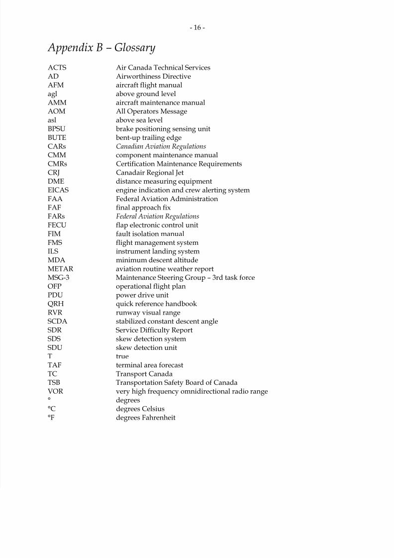
Appendix B – Glossary ACTS Air Canada Technical ServicesAD Airworthiness DirectiveAFM aircraft flight manual
agl above ground levelAMM aircraft maintenance manualAOM All Operators Messageasl above sea levelBPSU brake positioning sensing unitBUTE bent-up trailing edgeCARs Canadian Aviation Regulations CMM component maintenance manualCMRs Certification Maintenance RequirementsCRJ Canadair Regional JetDME distance measuring equipmentEICAS engine indication and crew alerting systemFAA Federal Aviation AdministrationFAF final approach fixFARs Federal Aviation Regulations FECU flap electronic control unitFIM fault isolation manualFMS flight management systemILS instrument landing systemMDA minimum descent altitudeMETAR aviation routine weather reportMSG-3 Maintenance Steering Group – 3rd task forceOFP operational flight plan
PDU power drive unitQRH quick reference handbookRVR runway visual rangeSCDA stabilized constant descent angleSDR Service Difficulty ReportSDS skew detection systemSDU skew detection unitT trueTAF terminal area forecastTC Transport CanadaTSB Transportation Safety Board of Canada
VOR very high frequency omnidirectional radio range° degrees°C degrees Celsius°F degrees Fahrenheit