fixtruck24.ru · trucknology® generation (tgs/tgx) i 1 1 1 1 2 2 3 3 4 7 8 8 10 10 11 11 11 11 12...
TRANSCRIPT
Guidelines to fi tting bodies
TRUCKNOLOGY® GENERATION (TGS/TGX)Edition 2013 Version 1.0
We reserve the right to make changes in the course of technical development.
© 2012 MAN Truck & Bus Aktiengesellschaft
Reprinting, reproduction or translation, even of excerpts, is not permitted without the written permission of MAN. All rights, in particular under copyright, are strictly reserved by MAN.
Trucknology® and MANTED® are registered trademarks of MAN Truck & Bus AG
Where designations are trademarks they are, even without the ® or ™ sign, acknowledged as the proprietor‘s protected marks.
P U B L I S H E R
MAN Truck & Bus AG(mentioned in the text below “MAN“)
SMTST Depar tment
D a c h a u e r S t r . 6 6 7D - 8 0 9 9 5 M u n i c h
E- Mail: esc @ man.eu
Fax: + 49 (0) 89 1580 4264
www.manted.de
TRUCKNOLOGY® GENERATION (TGS/TGX) I
111122334788
101011111111121314171822262627282829313234
TRUCKNOLOGY® GENERATION (TGS/TGX)
1. Applicability and legal agreements 1.1 Applicability 1.2 Legal agreements and approval procedure 1.2.1 Preconditions 1.2.2 Responsibility 1.2.3 Quality assurance 1.2.4 Approval 1.2.5 Submission of documents 1.2.6 Registration 1.2.7 Liability for defects 1.2.8 Product liability 1.2.9 Safety 1.2.10 Manuals from body and conversion companies 1.2.11 Limitation of liability for accessories/spare parts2. Product designations 2.1 Vehicle designation and wheel formula 2.1.1 Door designation 2.1.2 Variant descriptor 2.1.3 Wheel formula 2.1.4 Suffi x 2.2 Model number, vehicle identifi cation number, vehicle number, basic vehicle number 2.3 Use of logos 2.4 Cabs 2.5 Engine variants3. General 3.1 Axle overload, one-sided loading 3.2 Minimum front axle load 3.3 Wheels, rolling circumference 3.4 Permissible overhang 3.5 Theoretical wheelbase, overhang, theoretical axle centreline 3.6 Calculating the axle load and weighing procedure 3.7 Checking and adjustment procedures before and after body has been fitted 3.8 Notes on MAN Hydrodrive®

TRUCKNOLOGY® GENERATION (TGS/TGX) II
3434394040434345465252535354555656575757585860606063636363676868707173737478909191
4. Modifying the chassis 4.1 Frame material 4.1.1 Subframe material 4.2 Corrosion protection 4.3 Drill holes, riveted joints and screw connections on the frame 4.4 Modifying the frame 4.4.1 Welding the frame 4.4.2 Modifying the frame overhang 4.4.3 Modifi cations to the wheelbase 4.5 Retrofi tting additional equipment add-on components or accessories 4.5.1 Retrofi tting additional or larger fuel tanks after factory delivery 4.6 Propshafts 4.6.1 Single joint 4.6.2 Jointed shaft with two joints 4.6.3 Three-dimensional propshaft layout 4.6.3.1 Propshaft train 4.6.3.2 Forces in the propshaft system 4.6.4 Modifying the propshaft layout in the driveline of MAN chassis 4.7 Modifying the wheel formula 4.7.1 Safety-related components 4.8 Coupling devices 4.8.1 Basics 4.8.2 Trailer coupling, D value 4.9 Tractor units and converting the vehicle type - truck / tractor 4.9.1 Articulated vehicles 4.9.2 Converting trucks into tractor units or tractor units into trucks 4.10 Modifying the cab 4.10.1 General 4.10.2 Spoilers, roof extensions, roofwalk 4.10.3 Roof sleeper cabs 4.11 Add-on frame components 4.11.1 Rear underride guard 4.11.2 FUP - front underride protection 4.11.3 Sideguards 4.12 Modifi cations to engine systems 4.12.1 Modifi cations to the air intake system 4.12.2 Modifications to exhaust gas routing for engines 4.12.3 Modifi cations to the AdBlue® system 4.12.4 Engine cooling 4.12.5 Engine encapsulation, noise insulation 4.13 Fitting other manual gearboxes, automatic transmissions and transfer boxes
TRUCKNOLOGY® GENERATION (TGS/TGX) III
91919395969797979798
101101102105108108108109117118119119122124125126136136137
5. Bodies 5.1 General 5.1.1 Machinery Directive 5.1.2 CE marking 5.1.3 Affi xing the hazardous goods marker board to the front panel 5.2 Corrosion protection 5.3 Subframes 5.3.1 General 5.3.2 Permissible materials, yield points 5.3.3 Subframe design 5.3.4 Attaching subframes and bodies 5.3.5 Screw connections and riveted joints 5.3.6 Flexible connection 5.3.7 Rigid connection 5.4 Bodies 5.4.1 Testing of bodies 5.4.2 Platform and box bodies 5.4.3 Tail-lifts 5.4.4 Interchangeable containers 5.4.5 Self-supporting bodies without subframe 5.4.6 Single-pivot body 5.4.7 Tank and container bodies 5.4.8 Tippers 5.4.9 Set-down, sliding set-down and sliding roll-off tippers 5.4.10 Propping air-sprung vehicles 5.4.11 Loading cranes 5.4.12 Cable winches 5.4.13 Transport mixers 5.4.14 Car transporter
TRUCKNOLOGY® GENERATION (TGS/TGX) IV
138138138138138139140140143143144146146146147147148148148148149150
6. Electrics, electronics, wiring 6.1 General 6.2 Routing cables, earth cable 6.3 Handling batteries 6.3.1 Handling and maintaining the batteries 6.3.2 Handling and maintaining batteries with PAG technology 6.4 Additional wiring diagrams and wiring harness drawings 6.5 Fuses, additional power consumers 6.6 Lighting installations 6.7 Electromagnetic compatibility 6.8 Radio equipment and aerials 6.9 Interfaces on the vehicle, preparations for the body 6.9.1 Electrical connections for tail-lifts 6.9.2 Engine start-stop system 6.9.3 Tapping into the speed signal 6.9.4 Tapping into the reverse gear signal 6.10 Electronics 6.10.1 Display and instrumentation concept 6.10.2 Diagnostics concept and parameterisation using MAN-cats®
6.10.3 Parameterisation of the vehicle electronics 6.10.4 ESP yaw rate sensor 6.10.5 Emergency Brake Assist
TRUCKNOLOGY® GENERATION (TGS/TGX) V
153153153153153154155157157158158158159160161161161162166167169170173175175178180181181181183
7. Power take-off (See separate booklet)8. Brakes, lines 8.1 ALB, EBS braking system 8.2 Brake and compressed air lines 8.2.1 Basic principles 8.2.2 Voss 232 system plug connectors 8.2.3 Installing and attaching lines 8.2.4 Compressed air loss 8.3 Connecting additional air consumers 8.4 Retrofi tting continuous brakes not manufactured by MAN9. Calculations 9.1 Speed 9.2 Effi ciency 9.3 Tractive force 9.4 Gradeability 9.4.1 Distance travelled on uphill or downhill gradients 9.4.2 Angle of uphill or downhill gradient 9.4.3 Calculating the gradeability 9.5 Torque 9.6 Power output 9.7 Rotational speeds for power take-offs at the transfer case 9.8 Driving resistances 9.9 Turning circle 9.10 Axle load calculation 9.10.1 Performing an axle load calculation 9.10.2 Calculation of weight with trailing axle lifted 9.11 Support length for bodies without subframes 9.12 Coupling devices 9.12.1 Trailer coupling 9.12.2 Rigid drawbar trailers / central axle trailers 9.12.3 Fifth-wheel coupling
The ESC numbers stated in the illustrations are purely for internal reference. They are of no consequence to the reader.
If not otherwise stated: all dimensions in mm, all weights and loads in kg.
TRUCKNOLOGY® GENERATION (TGS/TGX) 1
1. Applicability and legal agreements
1.1 Applicability
The statements in this guide are binding. If technically feasible, exceptions will be approved only if a written request has been submitted to MAN, (for address see “Publisher“ above).
1.2 Legal agreements and approval procedure
1.2.1 Preconditions
In addition to this Guide, the company carrying out the work must observe all
• laws and decrees• accident prevention regulations• operating instructions
relating to the operation and construction of the vehicle. Standards are technical standards; they are therefore minimum requirements. Anyone who does not endeavour to observe these minimum requirements is regarded as operating negligently. Standards are binding when they form part of regulations.
Information given by MAN in reply to telephone enquiries is not binding unless confi rmed in writing. Enquiries are to be directed to the relevant MAN department. Information refers to conditions of use that are usual within Europe. Dimensions, weights and other basic data that differ from these must be taken into consideration when designing the body, mounting the body and designing the subframe. The company carrying out the work must ensure that the entire vehicle can withstand the conditions of use that it is expected to experience.
For certain types of equipment, such as loading cranes, tail-lifts, cable winches etc, the respective manufacturers have developed their own body regulations. If, when compared with this MAN Guide, they impose further conditions, then these too must be observed.
References to
• legal stipulations• accident prevention regulations• decrees from professional associations• work regulations• other guidelines and sources of information
are not in any way complete and are only intended as ideas for further information. They do not replace the company’s obligation to carry out its own checks.
Fuel consumption is considerably affected by modifi cations to the vehicle, by the body and its design and by the operation of equipment driven by the vehicle’s engine. It is therefore expected that the company carrying out the work implements a design that facilitates the lowest possible fuel consumption.
TRUCKNOLOGY® GENERATION (TGS/TGX) 2
1.2.2 Responsibility
The responsibility for proper
• design• production• installation of bodies• modifi cation to the chassis
always lies fully with the company that is manufacturing the body, installing it or carrying out modifi cations (manufacturer’s liability). This also applies if MAN has expressly approved the body or the modifi cation. Bodies/conversions that have been approved in writing by MAN do not release the body manufacturer from his responsibility for the product. Should the company carrying out the work detect a mistake either in the planning stage or in the intentions of
• the customer• the user• its own personnel• the vehicle manufacturer
then that mistake must be brought to the attention of the respective party.
The company is responsible for seeing that the vehicle’s
• operational safety• traffi c safety• maintenance possibilities and• handling characteristics
do not exhibit any disadvantageous properties.
With regard to traffi c safety, the company must operate in accordance with the state of the art and in line with the recognised rules in the fi eld in matters relating to
• the design• the production of bodies• the installation of bodies• the modifi cation of chassis• instructions and• operating instructions.
Diffi cult conditions of use must also be taken into account.
1.2.3 Quality assurance
In order to meet our customers’ high quality expectations and in view of international product/manufacturer liability legislation an on-going quality monitoring programme is also required for conversions and body manufacture/installation. This requires a functioning quality assurance system. It is recommended that the body manufacturer sets up and provides evidence of a quality system that complies with the general requirements and recognised rules (e.g. DIN EN ISO 9000 et seq. or VDA 8). Evidence of a qualifi ed system can be provided for example by:

TRUCKNOLOGY® GENERATION (TGS/TGX) 3
If MAN is the party awarding the contract for the body or conversion evidence of qualifi cation will be requested. MAN reserves the right to carry out its own system audit in accordance with VDA 8 or a corresponding process check at the supplier’s premises. VDA volume 8 has been agreed with the following body manufacturers’ associations: ZKF (Zentralverband Karosserie- und Fahrzeugtechnik – Central Association of Body and Vehicle Engineering) and BVM (Bundesverband Metall Vereinigung Deutscher Metallhandwerke – Federation of German Metal Trades Associations). It has also been agreed with the ZDH (Zentralverband des Deutschen Handwerks – Central Association of German Craft Trades).
Documents:VDA Volume 8 „Minimum quality assurance requirements for trailer, body manufacturers“, obtainable from the Verband der Automobilindustrie e.V (VDA) (German Engine Industry Association), http://www.vda-qmc.de.
1.2.4 Approval
Approval from MAN for a body or a chassis modifi cation is not required if the bodies or modifi cations are carried out in accordance with this Guide. If MAN approves a body or a chassis modifi cation, then this approval refers
• In the case of bodies only to the body’s fundamental compatibility with the respective chassis and the interfaces to the body (e.g. dimensions and mounting of the subframe)• In the case of chassis modifi cations only to the fact that, from a design point of view, the modifi cations to the chassis in question are fundamentally permissible.
The approval note that MAN enters on the submitted technical documents does not indicate a check on the
• Function• Design• Equipment of the body or the modifi cation.
Observance of this Guide does not free the user from responsibility to perform modifi cations and manufacture bodies properly from a technical point of view. The approval note only refers to such measures or components as are to be found in the submitted technical documents.
MAN reserves the right to refuse to issue approvals for bodies or modifi cations, even if a comparable approval has already been issued. Later submissions for approval are not automatically treated the same as earlier ones, because technical advances achieved in the interim period have to be taken into account.
MAN also reserves the right to change this Guide at any time or to issue instructions that differ from this Guide for individual chassis.
If several identical chassis have the same bodies or modifi cations MAN can, to simplify matters, issue a collective approval.
1.2.5 Submission of documents
Documents should only be sent to MAN if bodies/conversions diverge from this Guide. Before work begins on the vehicle, technical documents that require approval or inspection must be sent to MAN (for address see “Publisher“ above).
For an approval process to proceed swiftly, the following are required:
• Documents should be submitted in duplicate• The number of individual documents should be kept to a minimum• All the technical data and documents must be submitted.
TRUCKNOLOGY® GENERATION (TGS/TGX) 4
The following information should be included:
• Vehicle model (see Chapter 2.2 for model code) with - cab design - wheelbase - frame overhang• · Vehicle identifi cation number or vehicle number (if already available, see Chapter 2.2) Identifi cation of deviations from this Guide to Fitting Bodies in all documentation!• Loads and their load application points: - Forces from the body - Axle load calculation• Special conditions of use:• Subframe: - Material and cross-sectional data - Dimensions - Type of section - Arrangement of cross members in the subframe - Special features of the subframe design - Cross-section modifi cations - Additional reinforcements - Upsweeps, etc.• Means of connection: - Positioning (in relation to the chassis) - Type - Size - Number.
The following are not suffi cient for inspection or approval:
• Parts lists• Brochures• Photographs• Other not binding information.
Drawings are only valid if they bear the number that has been assigned to them. It is therefore not permitted to draw in the bodies or modifi cations on chassis drawings that have been provided by MAN and to submit these for approval.
1.2.6 Registration
National legislation on the registration of modifi ed vehicles shall be complied with.Modifi cations made to the chassis shall be presented to a technical vehicle inspection centre for approval.The company carrying out the work shall remain responsible, also after registration of the vehicle, should the competent authorities issue a registration certifi cate with a lack of knowledge relating to the operational safety of the product.
TRUCKNOLOGY® GENERATION (TGS/TGX) 5
Multi-stage co-operation modules in accordance with 2007/46/EC
I. ProcessIn line with the multi-stage process in accordance with Annex XVII of Directive 2007/46/EC each manufacturer is responsible for the approval and conformity of production of all systems, components or separate technical units manufactured by him or added by him to the previously built stage.
In accordance with 2007/46/EC the bodybuilder is a manufacturer in the second or further production stage.
II. ResponsibilitiesThe bodybuilder shall always remain responsible:
• For modifi cations made by him to the basic vehicle.• For parts already approved at an earlier stage if modifi cations made to the basic vehicle cause the approvals issued earlier for this vehicle to be no longer applicable.• For ensuring that modifi cations he has carried out comply with the corresponding national/international legislation, in particular those of the target country.• For ensuring that modifi cations he has carried out are presented to a technical vehicle inspection centre for approval.• For ensuring that compliance with legislation is documented in a corresponding manner (test report and/or approval or other documentation in accordance with the legal requirements of the target country).
MAN, as the manufacturer of the basic vehicle, shall always remain responsible:
• For providing upon request by the bodybuilder the available homologation documentation (EC/ECE approvals) for the scope of supply of the basic vehicle in electronic form.
III. Identifi cation of the vehicleThe respective vehicle shall be given a vehicle identifi cation number („VIN“) which MAN issues as the manufacturer of the incomplete basic vehicle.The requirements set forth in Annex XVII to Directive 2007/46/EC and the associated procedure instructions published together with it shall always apply.
IV. Conformity of production (CoP)The requirements set forth in the specifi c EC Directives and Annex X to Directive 2007/46/EC together with the requirements set forth in Annex 2 to the ECE Agreement of 1958 shall always apply. V. Provision of documentation for registration/the subsequent build stagesIn accordance with Annex XVII to Directive 2007/46/EC MAN, as manufacturer of the basic vehicle, shall provide the bodybuilder(s) with the available EC/ECE system approvals together with the Certifi cate of Conformity (CoC) 1) available for the basic vehicle in electronic form.
1) Only if the vehicle is EG-compliant and MAN has printed a CoC.
Case 1: Registration in Germany If MAN serves as general contractor („single invoice transactions“) the bodybuilder(s) is/are under an obligation, as manufacturer of the second stage(s), to provide the following documentation in electronic form:
Case A: The specifi c conditions of delivery provide for the acceptance/approval and registration process to be carried out by the vehicle manufacturer (MAN).
1. In the case of an existing and valid whole vehicle type-approval in accordance with 2007/46/EC for the manufacturing stages, a CoC.
2. Alternatively to 1: The test reports and approval documentation required for national individual approval procedures in accordance with Section 13 of the EC vehicle approval Directive.

TRUCKNOLOGY® GENERATION (TGS/TGX) 6
The latest time for submitting the above stated documentation in printable form is the day the completed vehicle is returned to the contractually agreed place of delivery.
The documentation shall be sent to the following e-mail address: [email protected].
In cases where MAN receives a CoC from the bodybuilder, then original certifi cates may only be generated by MAN on behalf of the bodybuilder.
Case B: The acceptance/approval and registration process is to be carried out by the contract partner or by the manufacturer of the fi nal completion stage of the vehicle.
1. None. The registration process is the responsibility of the contract partner or the manufacturer of the fi nal completion stage of the vehicle.
In all other cases the acceptance/approval and registration process is to be carried out by the manufacturer of the fi nal completion stage of the vehicle or by the corresponding contract partner.
Case 2: Registration outside Germany but inside the area of application of Directive 2007/46/EC If MAN serves as general contractor then the bodybuilder is under an obligation, as the fi nal stage manufacturer, to provide in electronic form, all the necessary approval/registration documentation for all modifi cations made during the subsequent manufacturing stages of the respective responsible sales organisation or importer which exceed the scope of the basic vehicle.
Irrespective of any general contractor status of the importers, the acceptance/approval and registration process is to be carried out by the manufacturer of the fi nal completion stage of the vehicle or by the corresponding contract partner.
The importer in the respective country or the corresponding contract partner have the authority and responsibility for the registration process.
MAN does not provide national data for registration purposes that exceeds that for incomplete vehicles set forth in Annex IX to Directive 2007/46/EC in its current form and as amended from time to time. This also applies in particular to national model codes and encrypted basic technical data.
MAN as a manufacturer reserves the right – following corresponding feasibility studies and economic implementation – and after reaching corresponding specifi cally applicable agreements with national sales organisations and importers, to provide data for national registration which exceeds the scope of that set forth above (e.g. vehicle’s manufacturing plates etc.). Corresponding enquiries shall be sent to the following e-mail address: [email protected]
VI. Confi dentiality agreementThe bodybuilder may not forward the approval documentation provided by MAN to any third parties without obtaining prior, express permission from MAN.
The forwarding of documentation that is directly associated with the registration of the vehicle in question to persons of the institutions listed below is excepted:
• MAN sales partners• Technical vehicle inspection centres or testing organisations• Approving authorities• Registration authorities or licensing centres acting for the government
TRUCKNOLOGY® GENERATION (TGS/TGX) 7
Type approval/homologation for
TiB (Truck in the Box),
CiB (Chassis in the Box),
BiB (Bus in the Box),
CKD (Complete Knocked Down),
SKD (Semi Knocked Down),
PKD (Partly Knocked Down)
For these versions MAN is not considered to be the manufacturer within the meaning of Directive 2007/46/EC – therefore, the responsibility for the homologation and registration process lies with the manufacturer of these vehicles.
In principle, the substance of the contracts respectively concluded with MAN shall apply.
In principle, MAN does not provide registration-related data for completed vehicles. Exceptions include homologation documentation for components subject to approval such as the engine. Such documentation will be provided by MAN in electronic form.
This does not however, preclude MAN from reserving the right – following corresponding feasibility studies and economic implementation – and after reaching corresponding specifi cally applicable agreements with national sales organisations and importers, from providing data for national registration which exceeds the scope of that set forth above (e.g. vehicle’s manufacturing plates etc.). Corresponding enquiries shall be sent to the homologation department at MAN.
1.2.7 Liability for defects
Liability claims in respect of defects only exist within the framework of the purchasing contract between buyer and seller. In accordance with this, liability for defects lies with the respective seller of the goods.
Claims against MAN are not valid if the fault that is the subject of the complaint was due to the fact that
• This Guide was not observed• In view of the purpose for which the vehicle is used, an unsuitable chassis has been selected• The damage to the chassis has been caused by - the body - the type of body mounting or how the body has been mounted - the modifi cation to the chassis - improper use.
TRUCKNOLOGY® GENERATION (TGS/TGX) 8
1.2.8 Product liability
Any faults in the work that are identifi ed by MAN are to be corrected. Insofar as is legally permissible, MAN disclaims all liability, in particular for consequential damage.
Product liability regulates:
• The liability of the manufacturer for its product or component• The compensation claim made by the manufacturer against whom a claim has been made against the manufacturer of an integral component, if the damage that has occurred is due to a fault in that component.
The company that has made the body or carried out the modifi cation is to relieve MAN of any liability to its customer or other third party if the damage that has occurred is due to the fact that
• The company did not observe this Guide• The body or chassis modifi cation has caused damage on account of its faulty - design - manufacture - installation - instructions• The fundamental rules that are laid down have not been complied with in any other way.
1.2.9 Safety
In order to ensure operational reliability and road safety and to maintain the validity of the warranty, the bodybuilder must observe the instructions given in these guidelines exactly. MAN shall not be liable for non-compliance.
Before commencing work on the body, making modifi cations or starting installation work, the bodybuilder must also have knowledge of the sections of the operator‘s manual that relate to the work he is completing. It will otherwise be impossible to recognise risks and other persons may be endangered.
MAN cannot be liable for reliability, safety and suitability if:
• Bodies are not designed and fi tted in accordance with these guidelines• Original parts or approved parts are replaced with other parts• Unauthorised modifi cations are made to the vehicle
Approvals by third parties, for example Technical Inspection Agencies or approvals from public authorities, shall not be considered suffi cient for precluding safety risks.
TRUCKNOLOGY® GENERATION (TGS/TGX) 9
Companies carrying out work on the chassis/vehicle are liable for any damage that may be caused by poor functional and operational safety or inadequate operating instructions. Therefore, MAN requires the body manufacturer or vehicle conversion company to:
• Ensure the highest possible safety, in line with the state of the art• Provide comprehensible, suffi cient operating instructions• Provide permanent, easily visible instruction plates on hazardous points for operators and/or third parties• Observe the necessary protection measures (e.g. fi re and explosion prevention)• Provide full toxicological information• Provide full environmental information.
Safety is top priority! All available technical means of avoiding incidents that will undermine operational safety are to be implemented. This applies equally to
• Active safety = prevention of accidents. This includes: - Driving safety achieved by the overall vehicle design, including the body - Safety as a consequence of the driver’s well-being achieved by keeping occupant stress caused by vibrations, noise, climatic conditions etc. to a minimum - Safety as a consequence of observation and perception, in particular through the correct design of lighting systems, warning equipment, providing suffi cient direct and indirect visibility - Safety as a consequence of operating equipment and controls this includes optimising the ease of operation of all equipment, including that of the body.• Passive safety = avoidance and reduction of the consequences of accidents. This includes: - Exterior safety such as the design of the outside of the vehicle and body with respect to deformation behaviour and the installation of protective devices - Interior safety including the protection of occupants of vehicles and cabs that are installed by the body builders.
Climatic and environmental conditions have effects on:
• Operational safety• Readiness for use• Operational performance• Service life• Cost-effectiveness.
Climatic and environmental conditions are, for example:
• The effects of temperature• Humidity• Aggressive substances• Sand and dust• Radiation.
Suffi cient space for all parts required to carry out a movement, including all pipes and cables, must be guaranteed. The operating instructions for MAN trucks provide information about the maintenance points on the vehicle. Regardless of what type of body is fi tted, good access to the maintenance points must be ensured in all cases. It must be possible to carry out maintenance unhindered and without having to remove any components. Suffi cient ventilation and/or cooling of the components is to be guaranteed.

TRUCKNOLOGY® GENERATION (TGS/TGX) 10
1.2.10 Manuals from body and conversion companies
In the event of a body being added or modifi cations to the vehicle being carried out, the operator of the vehicle is also entitled to receive operating instructions from the conversion company. All specifi c advantages offered by the product are of no use if the customer is not able to:
• Handle the product safely and properly• Use it rationally and effortlessly• Maintain it properly• Master all of its functions.
As a result, every vehicle body builder and converter must check his technical instructions for:
• Clarity• Completeness• Accuracy • Comprehensibility• Product-specifi c safety instructions.
Inadequate or incomplete operating instructions carry considerable risks for the user. Possible effects are:
• Reduced benefi t, because the advantages of the product remain unknown• Complaints and annoyance• Faults and damage, which are normally blamed on the chassis• Unexpected and unnecessary additional cost through repairs and time lost• A negative image and thereby less inclination to buy the same product or brand again.
Depending on the vehicle body or modifi cation, the operating personnel must be instructed about operation and maintenance. Such instruction must also include the possible effects on the static and dynamic performance of the vehicle.
1.2.11 Limitation of liability for accessories/spare parts
Accessories and spare parts that MAN has not manufactured or approved for use in its products may affect the traffi c safety and operational safety of the vehicle and create hazardous situations. MAN (or the seller) accepts no liability for claims of any kind resulting from a combination of the vehicle together with an accessory that was made by another manufacturer, regardless of whether MAN (or the seller) has sold the accessory itself or fi tted it to the vehicle (or the subject of the contract).
TRUCKNOLOGY® GENERATION (TGS/TGX) 11
2. Product designations
2.1 Vehicle designation and wheel formula
To enable unique and easily comprehensible identifi cation of the different variants new vehicle designations have been systematically introduced. The vehicle designation system is based on three levels:
- Door designation - Variant descriptor (in the sales and technical documentation e.g. data sheets, chassis drawings) - Model code.
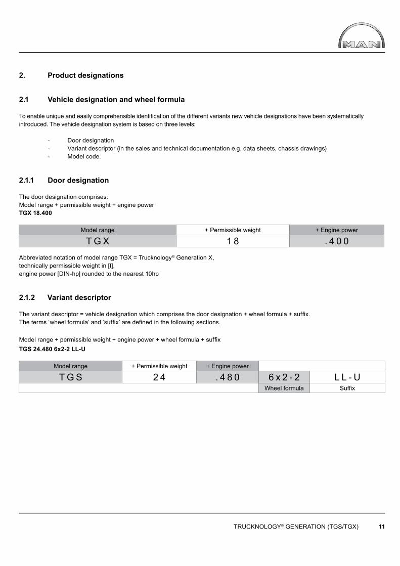
2.1.1 Door designation
The door designation comprises:Model range + permissible weight + engine powerTGX 18.400
Model range + Permissible weight + Engine power
T G X 1 8 . 4 0 0Abbreviated notation of model range TGX = Trucknology® Generation X, technically permissible weight in [t], engine power [DIN-hp] rounded to the nearest 10hp
2.1.2 Variant descriptor
The variant descriptor = vehicle designation which comprises the door designation + wheel formula + suffi x.The terms ‘wheel formula’ and ‘suffi x’ are defi ned in the following sections.
Model range + permissible weight + engine power + wheel formula + suffi xTGS 24.480 6x2-2 LL-U
Model range + Permissible weight + Engine power
T G S 2 4 . 4 8 0 6 x 2 - 2 L L - UWheel formula Suffi x
TRUCKNOLOGY® GENERATION (TGS/TGX) 12
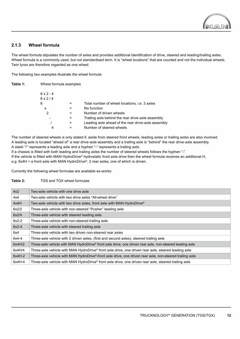
2.1.3 Wheel formula
The wheel formula stipulates the number of axles and provides additional identifi cation of drive, steered and leading/trailing axles. Wheel formula is a commonly used, but not standardised term. It is “wheel locations” that are counted and not the individual wheels. Twin tyres are therefore regarded as one wheel.
The following two examples illustrate the wheel formula:
Table 1: Wheel formula examples
6 x 2 - 4 6 x 2 / 4 6 = Total number of wheel locations, i.e. 3 axles x = No function 2 = Number of driven wheels - = Trailing axle behind the rear drive-axle assembly / = Leading axle ahead of the rear drive-axle assembly 4 = Number of steered wheels
The number of steered wheels is only stated if, aside from steered front wheels, leading axles or trailing axles are also involved. A leading axle is located “ahead of” a rear drive-axle assembly and a trailing axle is “behind” the rear drive-axle assembly. A slash “/” represents a leading axle and a hyphen “-” represents a trailing axle. If a chassis is fi tted with both leading and trailing axles the number of steered wheels follows the hyphen “-”. If the vehicle is fi tted with MAN HydroDrive® hydrostatic front axle drive then the wheel formula receives an additional H, e.g. 6x4H = a front axle with MAN HydroDrive®, 2 rear axles, one of which is driven.
Currently the following wheel formulae are available ex-works:
Table 2: TGS and TGX wheel formulae
4x2 Two-axle vehicle with one drive axle4x4 Two-axle vehicle with two drive axles “All-wheel drive”4x4H Two-axle vehicle with two drive axles, front axle with MAN HydroDrive®
6x2/2 Three-axle vehicle with non-steered “Pusher” leading axle 6x2/4 Three-axle vehicle with steered leading axle6x2-2 Three-axle vehicle with non-steered trailing axle6x2-4 Three-axle vehicle with steered trailing axle6x4 Three-axle vehicle with two driven non-steered rear axles6x4-4 Three-axle vehicle with 2 driven axles, (fi rst and second axles), steered trailing axle6x4H/2 Three-axle vehicle with MAN HydroDrive® front axle drive, one driven rear axle, non-steered leading axle6x4H/4 Three-axle vehicle with MAN HydroDrive® front axle drive, one driven rear axle, steered leading axle6x4H-2 Three-axle vehicle with MAN HydroDrive®-front axle drive, one driven rear axle, non-steered trailing axle6x4H-4 Three-axle vehicle with MAN HydroDrive® front axle drive, one driven rear axle, steered trailing axle
TRUCKNOLOGY® GENERATION (TGS/TGX) 13
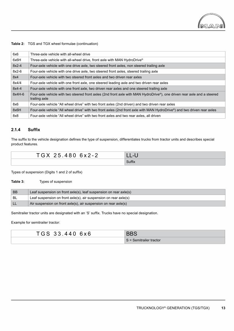
Table 2: TGS and TGX wheel formulae (continuation)
6x6 Three-axle vehicle with all-wheel drive6x6H Three-axle vehicle with all-wheel drive, front axle with MAN HydroDrive®
8x2-4 Four-axle vehicle with one drive axle, two steered front axles, non steered trailing axle8x2-6 Four-axle vehicle with one drive axle, two steered front axles, steered trailing axle8x4 Four-axle vehicle with two steered front axles and two driven rear axles8x4/4 Four-axle vehicle with one front axle, one steered leading axle and two driven rear axles8x4-4 Four-axle vehicle with one front axle, two driven rear axles and one steered trailing axle8x4H-6 Four-axle vehicle with two steered front axles (2nd front axle with MAN HydroDrive®), one driven rear axle and a steered
trailing axle8x6 Four-axle vehicle “All wheel drive” with two front axles (2nd driven) and two driven rear axles8x6H Four-axle vehicle “All wheel drive” with two front axles (2nd front axle with MAN HydroDrive®) and two driven rear axles8x8 Four-axle vehicle “All wheel drive” with two front axles and two rear axles, all driven
2.1.4 Suffi x
The suffi x to the vehicle designation defi nes the type of suspension, differentiates trucks from tractor units and describes special product features.
T G X 2 5 . 4 8 0 6 x 2 - 2 LL-USuffi x
Types of suspension (Digits 1 and 2 of suffi x)
Table 3: Types of suspension
BB Leaf suspension on front axle(s), leaf suspension on rear axle(s)BL Leaf suspension on front axle(s), air suspension on rear axle(s)LL Air suspension on front axle(s), air suspension on rear axle(s)
Semitrailer tractor units are designated with an ‘S’ suffi x. Trucks have no special designation.
Example for semitrailer tractor:
T G S 3 3 . 4 4 0 6 x 6 BBSS = Semitrailer tractor
TRUCKNOLOGY® GENERATION (TGS/TGX) 14
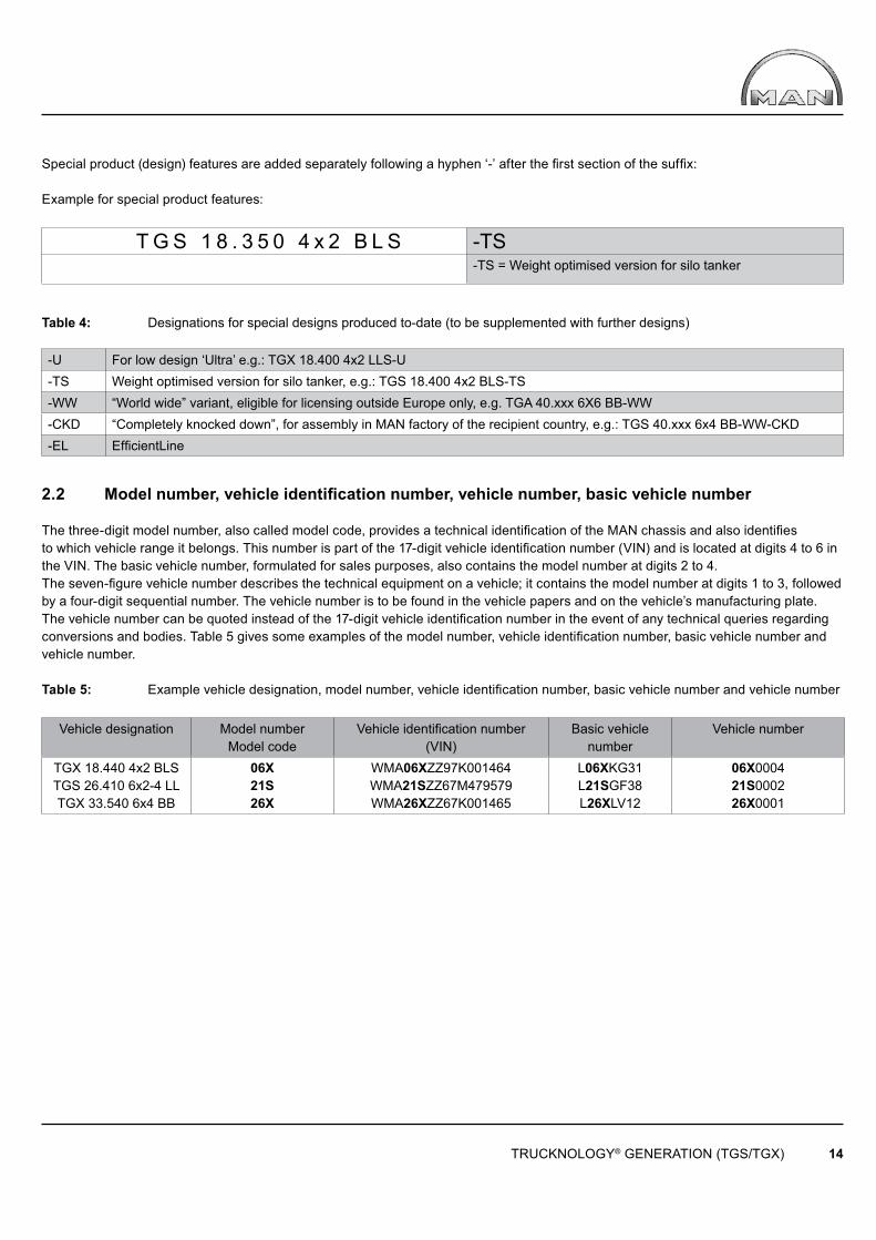
Special product (design) features are added separately following a hyphen ‘-’ after the fi rst section of the suffi x:
Example for special product features:
T G S 1 8 . 3 5 0 4 x 2 B L S -TS-TS = Weight optimised version for silo tanker
Table 4: Designations for special designs produced to-date (to be supplemented with further designs)
-U For low design ‘Ultra’ e.g.: TGX 18.400 4x2 LLS-U-TS Weight optimised version for silo tanker, e.g.: TGS 18.400 4x2 BLS-TS-WW “World wide” variant, eligible for licensing outside Europe only, e.g. TGA 40.xxx 6X6 BB-WW-CKD “Completely knocked down”, for assembly in MAN factory of the recipient country, e.g.: TGS 40.xxx 6x4 BB-WW-CKD-EL Effi cientLine
2.2 Model number, vehicle identifi cation number, vehicle number, basic vehicle number
The three-digit model number, also called model code, provides a technical identifi cation of the MAN chassis and also identifi es to which vehicle range it belongs. This number is part of the 17-digit vehicle identifi cation number (VIN) and is located at digits 4 to 6 in the VIN. The basic vehicle number, formulated for sales purposes, also contains the model number at digits 2 to 4. The seven-fi gure vehicle number describes the technical equipment on a vehicle; it contains the model number at digits 1 to 3, followed by a four-digit sequential number. The vehicle number is to be found in the vehicle papers and on the vehicle’s manufacturing plate. The vehicle number can be quoted instead of the 17-digit vehicle identifi cation number in the event of any technical queries regarding conversions and bodies. Table 5 gives some examples of the model number, vehicle identifi cation number, basic vehicle number and vehicle number.
Table 5: Example vehicle designation, model number, vehicle identifi cation number, basic vehicle number and vehicle number
Vehicle designation Model numberModel code
Vehicle identifi cation number(VIN)
Basic vehicle number
Vehicle number
TGX 18.440 4x2 BLSTGS 26.410 6x2-4 LLTGX 33.540 6x4 BB
06X21S26X
WMA06XZZ97K001464WMA21SZZ67M479579WMA26XZZ67K001465
L06XKG31L21SGF38L26XLV12
06X000421S000226X0001
TRUCKNOLOGY® GENERATION (TGS/TGX) 15
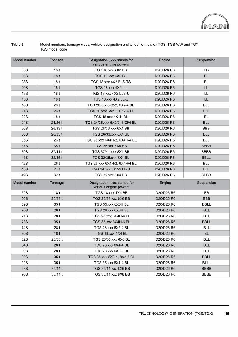
Table 6: Model numbers, tonnage class, vehicle designation and wheel formula on TGS, TGS-WW and TGX TGS model code
Model number Tonnage Designation , xxx stands forvarious engine powers
Engine Suspension
03S 18 t TGS 18.xxx 4X2 BB D20/D26 R6 BB06S 18 t TGS 18.xxx 4X2 BL D20/D26 R6 BL08S 18 t TGS 18.xxx 4X2 BLS-TS D20/D26 R6 BL10S 18 t TGS 18.xxx 4X2 LL D20/D26 R6 LL13S 18 t TGS 18.xxx 4X2 LLS-U D20/D26 R6 LL15S 18 t TGS 18.xxx 4X2 LL-U D20/D26 R6 LL18S 26 t TGS 26.xxx 6X2-2, 6X2-4 BL D20/D26 R6 BLL21S 26 t TGS 26.xxx 6X2-2, 6X2-4 LL D20/D26 R6 LLL22S 18 t TGS 18.xxx 4X4H BL D20/D26 R6 BL24S 24/26 t TGS 24/26.xxx 6X2/2, 6X2/4 BL D20/D26 R6 BLL26S 26/33 t TGS 26/33.xxx 6X4 BB D20/D26 R6 BBB30S 26/33 t TGS 26/33.xxx 6X4 BL D20/D26 R6 BLL35S 26 t TGS 26.xxx 6X4H-2, 6X4H-4 BL D20/D26 R6 BLL37S 35 t TGS 35.xxx 8X4 BB D20/D26 R6 BBBB39S 37/41 t TGS 37/41.xxx 8X4 BB D20/D26 R6 BBBB41S 32/35 t TGS 32/35.xxx 8X4 BL D20/D26 R6 BBLL42S 26 t TGS 26.xxx 6X4H/2, 6X4H/4 BL D20/D26 R6 BLL45S 24 t TGS 24.xxx 6X2-2 LL-U D20/D26 R6 LLL49S 32 t TGS 32.xxx 8X4 BB D20/D26 R6 BBBB
Model number Tonnage Designation , xxx stands forvarious engine powers
Engine Suspension
52S 18 t TGS 18.xxx 4X4 BB D20/D26 R6 BB56S 26/33 t TGS 26/33.xxx 6X6 BB D20/D26 R6 BBB59S 35 t TGS 35.xxx 8X6H BL D20/D26 R6 BBLL70S 26 t TGS 26.xxx 6X6H BL D20/D26 R6 BLL71S 28 t TGS 28.xxx 6X4H-4 BL D20/D26 R6 BLL73S 35 t TGS 35.xxx 8X4H-6 BL D20/D26 R6 BBLL74S 28 t TGS 28.xxx 6X2-4 BL D20/D26 R6 BLL80S 18 t TGS 18.xxx 4X4 BL D20/D26 R6 BL82S 26/33 t TGS 26/33.xxx 6X6 BL D20/D26 R6 BLL84S 28 t TGS 28.xxx 6X4-4 BL D20/D26 R6 BLL89S 28 t TGS 28.xxx 6X2-2 BL D20/D26 R6 BLL90S 35 t TGS 35.xxx 8X2-4, 8X2-6 BL D20/D26 R6 BBLL92S 35 t TGS 35.xxx 8X4-4 BL D20/D26 R6 BLLL93S 35/41 t TGS 35/41.xxx 8X6 BB D20/D26 R6 BBBB96S 35/41 t TGS 35/41.xxx 8X8 BB D20/D26 R6 BBBB
TRUCKNOLOGY® GENERATION (TGS/TGX) 16
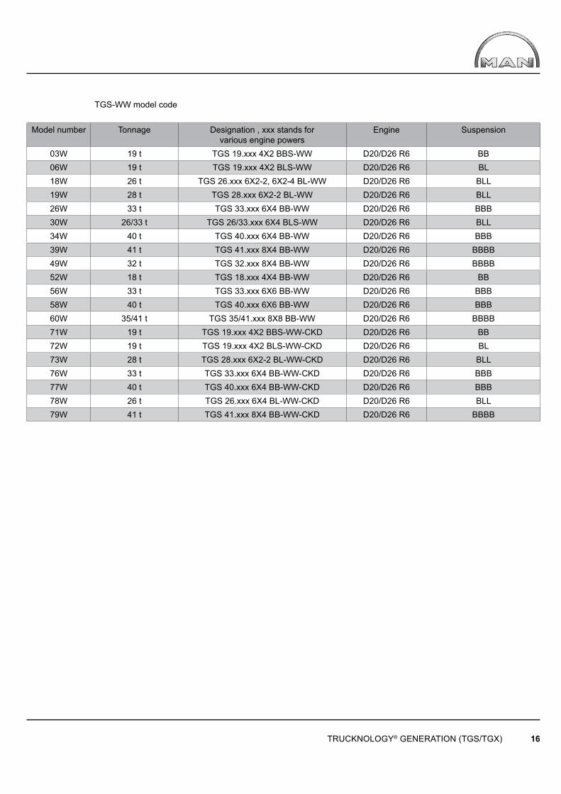
TGS-WW model code
Model number Tonnage Designation , xxx stands forvarious engine powers
Engine Suspension
03W 19 t TGS 19.xxx 4X2 BBS-WW D20/D26 R6 BB06W 19 t TGS 19.xxx 4X2 BLS-WW D20/D26 R6 BL18W 26 t TGS 26.xxx 6X2-2, 6X2-4 BL-WW D20/D26 R6 BLL19W 28 t TGS 28.xxx 6X2-2 BL-WW D20/D26 R6 BLL26W 33 t TGS 33.xxx 6X4 BB-WW D20/D26 R6 BBB30W 26/33 t TGS 26/33.xxx 6X4 BLS-WW D20/D26 R6 BLL34W 40 t TGS 40.xxx 6X4 BB-WW D20/D26 R6 BBB39W 41 t TGS 41.xxx 8X4 BB-WW D20/D26 R6 BBBB49W 32 t TGS 32.xxx 8X4 BB-WW D20/D26 R6 BBBB52W 18 t TGS 18.xxx 4X4 BB-WW D20/D26 R6 BB56W 33 t TGS 33.xxx 6X6 BB-WW D20/D26 R6 BBB58W 40 t TGS 40.xxx 6X6 BB-WW D20/D26 R6 BBB60W 35/41 t TGS 35/41.xxx 8X8 BB-WW D20/D26 R6 BBBB71W 19 t TGS 19.xxx 4X2 BBS-WW-CKD D20/D26 R6 BB72W 19 t TGS 19.xxx 4X2 BLS-WW-CKD D20/D26 R6 BL73W 28 t TGS 28.xxx 6X2-2 BL-WW-CKD D20/D26 R6 BLL76W 33 t TGS 33.xxx 6X4 BB-WW-CKD D20/D26 R6 BBB77W 40 t TGS 40.xxx 6X4 BB-WW-CKD D20/D26 R6 BBB78W 26 t TGS 26.xxx 6X4 BL-WW-CKD D20/D26 R6 BLL79W 41 t TGS 41.xxx 8X4 BB-WW-CKD D20/D26 R6 BBBB
TRUCKNOLOGY® GENERATION (TGS/TGX) 17
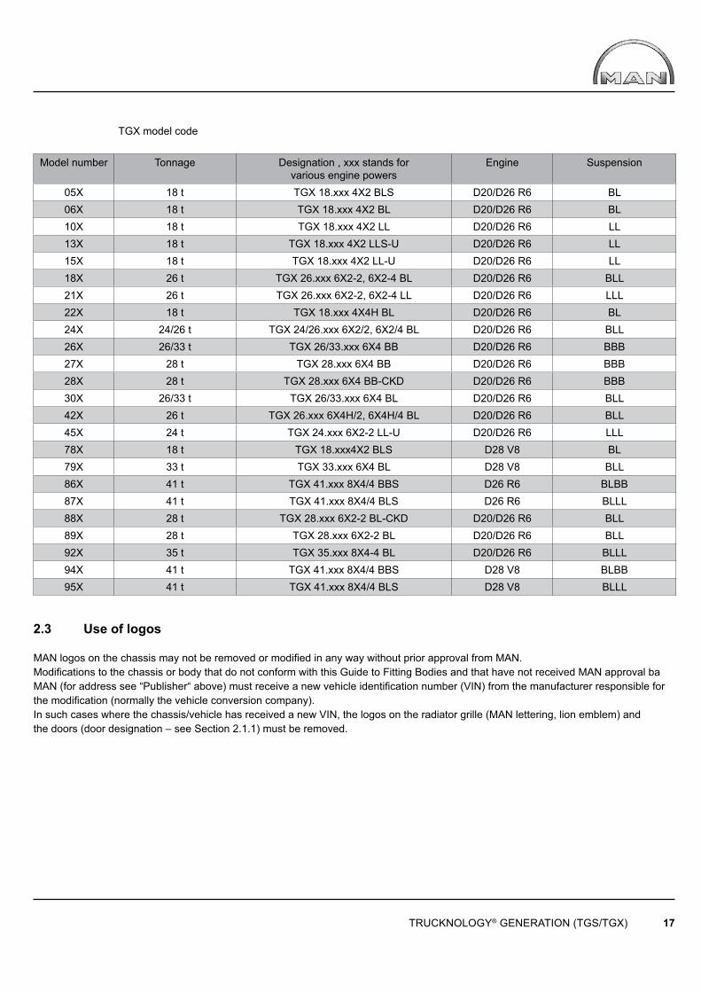
TGX model code
Model number Tonnage Designation , xxx stands forvarious engine powers
Engine Suspension
05X 18 t TGX 18.xxx 4X2 BLS D20/D26 R6 BL06X 18 t TGX 18.xxx 4X2 BL D20/D26 R6 BL10X 18 t TGX 18.xxx 4X2 LL D20/D26 R6 LL13X 18 t TGX 18.xxx 4X2 LLS-U D20/D26 R6 LL15X 18 t TGX 18.xxx 4X2 LL-U D20/D26 R6 LL18X 26 t TGX 26.xxx 6X2-2, 6X2-4 BL D20/D26 R6 BLL21X 26 t TGX 26.xxx 6X2-2, 6X2-4 LL D20/D26 R6 LLL22X 18 t TGX 18.xxx 4X4H BL D20/D26 R6 BL24X 24/26 t TGX 24/26.xxx 6X2/2, 6X2/4 BL D20/D26 R6 BLL26X 26/33 t TGX 26/33.xxx 6X4 BB D20/D26 R6 BBB27X 28 t TGX 28.xxx 6X4 BB D20/D26 R6 BBB28X 28 t TGX 28.xxx 6X4 BB-CKD D20/D26 R6 BBB30X 26/33 t TGX 26/33.xxx 6X4 BL D20/D26 R6 BLL42X 26 t TGX 26.xxx 6X4H/2, 6X4H/4 BL D20/D26 R6 BLL45X 24 t TGX 24.xxx 6X2-2 LL-U D20/D26 R6 LLL78X 18 t TGX 18.xxx4X2 BLS D28 V8 BL79X 33 t TGX 33.xxx 6X4 BL D28 V8 BLL86X 41 t TGX 41.xxx 8X4/4 BBS D26 R6 BLBB87X 41 t TGX 41.xxx 8X4/4 BLS D26 R6 BLLL88X 28 t TGX 28.xxx 6X2-2 BL-CKD D20/D26 R6 BLL89X 28 t TGX 28.xxx 6X2-2 BL D20/D26 R6 BLL92X 35 t TGX 35.xxx 8X4-4 BL D20/D26 R6 BLLL94X 41 t TGX 41.xxx 8X4/4 BBS D28 V8 BLBB95X 41 t TGX 41.xxx 8X4/4 BLS D28 V8 BLLL
2.3 Use of logos
MAN logos on the chassis may not be removed or modifi ed in any way without prior approval from MAN. Modifi cations to the chassis or body that do not conform with this Guide to Fitting Bodies and that have not received MAN approval baMAN (for address see “Publisher“ above) must receive a new vehicle identifi cation number (VIN) from the manufacturer responsible for the modifi cation (normally the vehicle conversion company).In such cases where the chassis/vehicle has received a new VIN, the logos on the radiator grille (MAN lettering, lion emblem) and the doors (door designation – see Section 2.1.1) must be removed.
TRUCKNOLOGY® GENERATION (TGS/TGX) 18
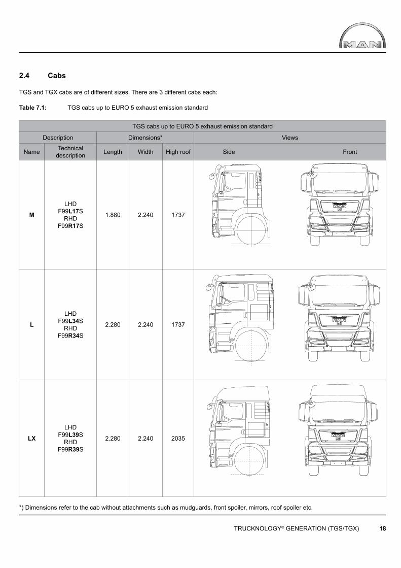
2.4 Cabs
TGS and TGX cabs are of different sizes. There are 3 different cabs each:
Table 7.1: TGS cabs up to EURO 5 exhaust emission standard
TGS cabs up to EURO 5 exhaust emission standard
Description Dimensions* Views
Name Technicaldescription Length Width High roof Side Front
M
LHDF99L17S
RHDF99R17S
1.880 2.240 1737
L
LHDF99L34S
RHDF99R34S
2.280 2.240 1737
LX
LHDF99L39S
RHDF99R39S
2.280 2.240 2035
*) Dimensions refer to the cab without attachments such as mudguards, front spoiler, mirrors, roof spoiler etc.

TRUCKNOLOGY® GENERATION (TGS/TGX) 19
Table 7.2: TGS cabs from EURO 6 exhaust emission standard
TGS cabs from EURO 6 exhaust emission standard
Description Dimensions* Views
Name TechnicalDescription
Length Width High roof Side Front
M
LHDF99L17S
RHDF99R17S
1.880 2.240 1737
L
LHDF99L34S
RHDF99R34S
2.280 2.240 1737
LX
LHDF99L39S
RHDF99R39S
2.280 2.240 2035
*) Dimensions refer to the cab without attachments such as mudguards, front spoiler, mirrors, roof spoiler etc.
TRUCKNOLOGY® GENERATION (TGS/TGX) 20
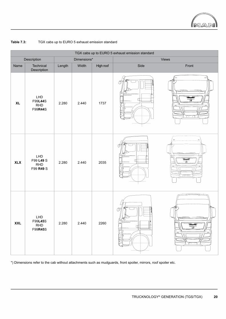
Table 7.3: TGX cabs up to EURO 5 exhaust emission standard
TGX cabs up to EURO 5 exhaust emission standard
Description Dimensions* Views
Name TechnicalDescription
Length Width High roof Side Front
XL
LHDF99L44S
RHDF99R44S
2.280 2.440 1737vavavaVAVA
XLX
LHD F99 L49 S
RHD F99 R49 S
2.280 2.440 2035 va
XXL
LHDF99L45S
RHDF99R45S
2.280 2.440 2260
*) Dimensions refer to the cab without attachments such as mudguards, front spoiler, mirrors, roof spoiler etc.

TRUCKNOLOGY® GENERATION (TGS/TGX) 21
Table 7.4: TGX cabs from EURO 6 exhaust emission standard
TGX bei Abgasnorm Euro 6
Description Dimensions* View
Name TechnicalDescription
Length Width High roof Side Front
XL
LHDF99L44S
RHDF99R44S
2.280 2.440 1737
XLX
LHD F99 L49 S
RHD F99 R49 S
2.280 2.440 2035
XXL
LHDF99L45S
RHDF99R45S
2.280 2.440 2260
*) Dimensions refer to the cab without attachments such as mudguards, front spoiler, mirrors, roof spoiler etc.
TRUCKNOLOGY® GENERATION (TGS/TGX) 22
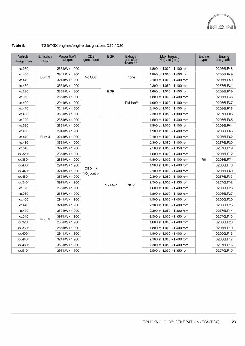
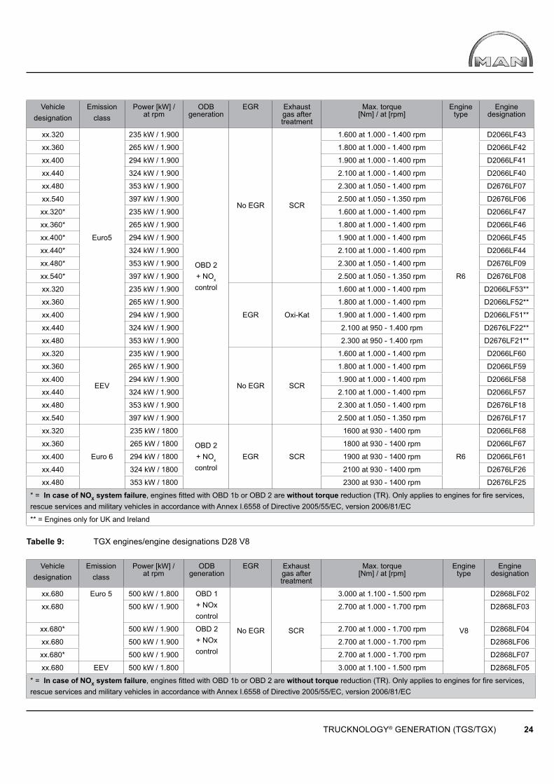
2.5 Engine variants
In-line six-cylinder Diesel engines (R6) of the D20/D26 Common Rail range are installed in the TGS and TGX (= 1st – 3rd digits of the engine designation). The engines are available in Euro 4 with cooled EGR and PM-Kat® plus Euro 5 with SCR technology. A newly developed V8 Common Rail engine from the D28 family supplements the TGX range. In accordance with European regulations the engines are fi tted with on board diagnosis, including a NOx analyser (with engine torque limitation in the event of NOx analyser failure). and exhaust gas aftertreatment in accordance with the following table:
Abbreviations:
EGR: Exhaust Gas RecirculationEEV: Enhanced Environmentally friendly VehicleOBD: On-Board Diagnostics PM-Kat®: Particulate Matter (particle fi lter)SCR: Selective Catalytic Reduction using “AdBlue” as the reducing agent
TRUCKNOLOGY® GENERATION (TGS/TGX) 23
Table 8: TGS/TGX engines/engine designations D20 / D26
Vehicle designation
Emission class
Power [kW] /at rpm
ODB generation
EGR Exhaust gas after treatment
Max. torque [Nm] / at [rpm]
Engine type
Engine designation
xx.360
Euro 3
265 kW / 1.900
No OBD
EGR
None
1.800 at 1.000 - 1.400 rpm
R6
D2066LF48
xx.400 294 kW / 1.900 1.900 at 1.000 - 1.400 rpm D2066LF49
xx.440 324 kW / 1.900 2.100 at 1.000 - 1.400 rpm D2066LF50
xx.480 353 kW / 1.900 2.300 at 1.050 - 1.400 rpm D2676LF31
xx.320
Euro 4
235 kW / 1.900
OBD 1 + NOx control
PM-Kat®
1.600 at 1.000 - 1.400 rpm D2066LF39
xx.360 265 kW / 1.900 1.800 at 1.000 - 1.400 rpm D2066LF38
xx.400 294 kW / 1.900 1.900 at 1.000 - 1.400 rpm D2066LF37
xx.440 324 kW / 1.900 2.100 at 1.000 - 1.400 rpm D2066LF36
xx.480 353 kW / 1.900 2.300 at 1.050 - 1.300 rpm D2676LF05
xx.320 235 kW / 1.900
No EGR SCR
1.600 at 1.000 - 1.400 rpm D2066LF65
xx.360 265 kW / 1.900 1.800 at 1.000 - 1.400 rpm D2066LF64
xx.400 294 kW / 1.900 1.900 at 1.000 - 1.400 rpm D2066LF63
xx.440 324 kW / 1.900 2.100 at 1.000 - 1.400 rpm D2066LF62
xx.480 353 kW / 1.900 2.300 at 1.050 - 1.300 rpm D2676LF20
xx.540 397 kW / 1.900 2.500 at 1.050 - 1.350 rpm D2676LF19
xx.320* 235 kW / 1.900 1.600 at 1.000 - 1.400 rpm D2066LF72
xx.360* 265 kW / 1.900 1.800 at 1.000 - 1.400 rpm D2066LF71
xx.400* 294 kW / 1.900 1.900 at 1.000 - 1.400 rpm D2066LF70
xx.440* 324 kW / 1.900 2.100 at 1.000 - 1.400 rpm D2066LF69
xx.480* 353 kW / 1.900 2.300 at 1.050 - 1.400 rpm D2676LF33
xx.540* 397 kW / 1.900 2.500 at 1.050 - 1.350 rpm D2676LF32
xx.320
Euro 5
235 kW / 1.900 1.600 at 1.000 - 1.400 rpm D2066LF28
xx.360 265 kW / 1.900 1.800 at 1.000 - 1.400 rpm D2066LF27
xx.400 294 kW / 1.900 1.900 at 1.000 - 1.400 rpm D2066LF26
xx.440 324 kW / 1.900 2.100 at 1.000 - 1.400 rpm D2066LF25
xx.480 353 kW / 1.900 2.300 at 1.050 - 1.300 rpm D2676LF14
xx.540 397 kW / 1.900 2.500 at 1.050 - 1.350 rpm D2676LF13
xx.320* 235 kW / 1.900 1.600 at 1.000 - 1.400 rpm D2066LF20
xx.360* 265 kW / 1.900 1.800 at 1.000 - 1.400 rpm D2066LF19
xx.400* 294 kW / 1.900 1.900 at 1.000 - 1.400 rpm D2066LF18
xx.440* 324 kW / 1.900 2.100 at 1.000 - 1.400 rpm D2066LF17
xx.480* 353 kW / 1.900 2.300 at 1.050 - 1.400 rpm D2676LF16
xx.540* 397 kW / 1.900 2.500 at 1.050 - 1.350 rpm D2676LF15
TRUCKNOLOGY® GENERATION (TGS/TGX) 24
Vehicle designation
Emission class
Power [kW] /at rpm
ODB generation
EGR
Exhaust gas after treatment
Max. torque [Nm] / at [rpm]
Engine type
Engine designation
xx.320
Euro5
235 kW / 1.900
OBD 2 + NOx control
No EGR SCR
1.600 at 1.000 - 1.400 rpm
R6
D2066LF43
xx.360 265 kW / 1.900 1.800 at 1.000 - 1.400 rpm D2066LF42
xx.400 294 kW / 1.900 1.900 at 1.000 - 1.400 rpm D2066LF41
xx.440 324 kW / 1.900 2.100 at 1.000 - 1.400 rpm D2066LF40
xx.480 353 kW / 1.900 2.300 at 1.050 - 1.400 rpm D2676LF07
xx.540 397 kW / 1.900 2.500 at 1.050 - 1.350 rpm D2676LF06
xx.320* 235 kW / 1.900 1.600 at 1.000 - 1.400 rpm D2066LF47
xx.360* 265 kW / 1.900 1.800 at 1.000 - 1.400 rpm D2066LF46
xx.400* 294 kW / 1.900 1.900 at 1.000 - 1.400 rpm D2066LF45
xx.440* 324 kW / 1.900 2.100 at 1.000 - 1.400 rpm D2066LF44
xx.480* 353 kW / 1.900 2.300 at 1.050 - 1.400 rpm D2676LF09
xx.540* 397 kW / 1.900 2.500 at 1.050 - 1.350 rpm D2676LF08
xx.320 235 kW / 1.900
EGR Oxi-Kat
1.600 at 1.000 - 1.400 rpm D2066LF53**
xx.360 265 kW / 1.900 1.800 at 1.000 - 1.400 rpm D2066LF52**
xx.400 294 kW / 1.900 1.900 at 1.000 - 1.400 rpm D2066LF51**
xx.440 324 kW / 1.900 2.100 at 950 - 1.400 rpm D2676LF22**
xx.480 353 kW / 1.900 2.300 at 950 - 1.400 rpm D2676LF21**
xx.320
EEV
235 kW / 1.900
No EGR SCR
1.600 at 1.000 - 1.400 rpm D2066LF60
xx.360 265 kW / 1.900 1.800 at 1.000 - 1.400 rpm D2066LF59
xx.400 294 kW / 1.900 1.900 at 1.000 - 1.400 rpm D2066LF58
xx.440 324 kW / 1.900 2.100 at 1.000 - 1.400 rpm D2066LF57
xx.480 353 kW / 1.900 2.300 at 1.050 - 1.400 rpm D2676LF18
xx.540 397 kW / 1.900 2.500 at 1.050 - 1.350 rpm D2676LF17
xx.320
Euro 6
235 kW / 1800
OBD 2 + NOx control
EGR SCR
1600 at 930 - 1400 rpm
R6
D2066LF68
xx.360 265 kW / 1800 1800 at 930 - 1400 rpm D2066LF67
xx.400 294 kW / 1800 1900 at 930 - 1400 rpm D2066LF61
xx.440 324 kW / 1800 2100 at 930 - 1400 rpm D2676LF26
xx.480 353 kW / 1800 2300 at 930 - 1400 rpm D2676LF25
* = In case of NOX system failure, engines fi tted with OBD 1b or OBD 2 are without torque reduction (TR). Only applies to engines for fi re services, rescue services and military vehicles in accordance with Annex I.6558 of Directive 2005/55/EC, version 2006/81/EC
** = Engines only for UK and Ireland
Tabelle 9: TGX engines/engine designations D28 V8
Vehicle designation
Emission class
Power [kW] /at rpm
ODB generation
EGR
Exhaust gas after treatment
Max. torque [Nm] / at [rpm]
Engine type
Engine designation
xx.680 Euro 5 500 kW / 1.800 OBD 1 + NOx control
No EGR SCR
3.000 at 1.100 - 1.500 rpm
V8
D2868LF02
xx.680 500 kW / 1.900 2.700 at 1.000 - 1.700 rpm D2868LF03
xx.680* 500 kW / 1.900 OBD 2 + NOx control
2.700 at 1.000 - 1.700 rpm D2868LF04
xx.680 500 kW / 1.900 2.700 at 1.000 - 1.700 rpm D2868LF06
xx.680* 500 kW / 1.900 2.700 at 1.000 - 1.700 rpm D2868LF07
xx.680 EEV 500 kW / 1.800 3.000 at 1.100 - 1.500 rpm D2868LF05
* = In case of NOX system failure, engines fi tted with OBD 1b or OBD 2 are without torque reduction (TR). Only applies to engines for fi re services, rescue services and military vehicles in accordance with Annex I.6558 of Directive 2005/55/EC, version 2006/81/EC
TRUCKNOLOGY® GENERATION (TGS/TGX) 25
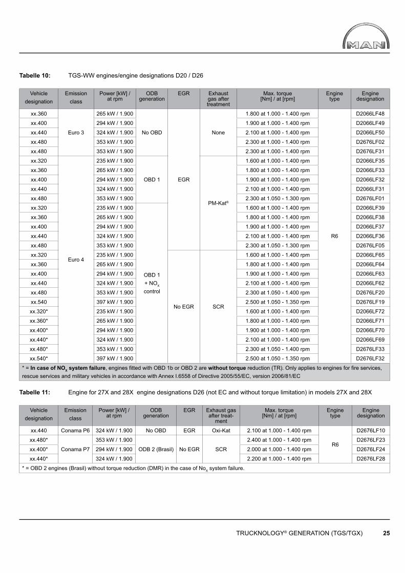
Tabelle 10: TGS-WW engines/engine designations D20 / D26
Vehicle designation
Emission class
Power [kW] /at rpm
ODB generation
EGR Exhaust gas after treatment
Max. torque [Nm] / at [rpm]
Engine type
Engine designation
xx.360
Euro 3
265 kW / 1.900
No OBD
EGR
None
1.800 at 1.000 - 1.400 rpm
R6
D2066LF48
xx.400 294 kW / 1.900 1.900 at 1.000 - 1.400 rpm D2066LF49
xx.440 324 kW / 1.900 2.100 at 1.000 - 1.400 rpm D2066LF50
xx.480 353 kW / 1.900 2.300 at 1.000 - 1.400 rpm D2676LF02
xx.480 353 kW / 1.900 2.300 at 1.000 - 1.400 rpm D2676LF31
xx.320
Euro 4
235 kW / 1.900
OBD 1
PM-Kat®
1.600 at 1.000 - 1.400 rpm D2066LF35
xx.360 265 kW / 1.900 1.800 at 1.000 - 1.400 rpm D2066LF33
xx.400 294 kW / 1.900 1.900 at 1.000 - 1.400 rpm D2066LF32
xx.440 324 kW / 1.900 2.100 at 1.000 - 1.400 rpm D2066LF31
xx.480 353 kW / 1.900 2.300 at 1.050 - 1.300 rpm D2676LF01
xx.320 235 kW / 1.900
OBD 1 + NOX control
1.600 at 1.000 - 1.400 rpm D2066LF39
xx.360 265 kW / 1.900 1.800 at 1.000 - 1.400 rpm D2066LF38
xx.400 294 kW / 1.900 1.900 at 1.000 - 1.400 rpm D2066LF37
xx.440 324 kW / 1.900 2.100 at 1.000 - 1.400 rpm D2066LF36
xx.480 353 kW / 1.900 2.300 at 1.050 - 1.300 rpm D2676LF05
xx.320 235 kW / 1.900
No EGR SCR
1.600 at 1.000 - 1.400 rpm D2066LF65
xx.360 265 kW / 1.900 1.800 at 1.000 - 1.400 rpm D2066LF64
xx.400 294 kW / 1.900 1.900 at 1.000 - 1.400 rpm D2066LF63
xx.440 324 kW / 1.900 2.100 at 1.000 - 1.400 rpm D2066LF62
xx.480 353 kW / 1.900 2.300 at 1.050 - 1.400 rpm D2676LF20
xx.540 397 kW / 1.900 2.500 at 1.050 - 1.350 rpm D2676LF19
xx.320* 235 kW / 1.900 1.600 at 1.000 - 1.400 rpm D2066LF72
xx.360* 265 kW / 1.900 1.800 at 1.000 - 1.400 rpm D2066LF71
xx.400* 294 kW / 1.900 1.900 at 1.000 - 1.400 rpm D2066LF70
xx.440* 324 kW / 1.900 2.100 at 1.000 - 1.400 rpm D2066LF69
xx.480* 353 kW / 1.900 2.300 at 1.050 - 1.400 rpm D2676LF33
xx.540* 397 kW / 1.900 2.500 at 1.050 - 1.350 rpm D2676LF32
* = In case of NOX system failure, engines fi tted with OBD 1b or OBD 2 are without torque reduction (TR). Only applies to engines for fi re services, rescue services and military vehicles in accordance with Annex I.6558 of Directive 2005/55/EC, version 2006/81/EC
Tabelle 11: Engine for 27X and 28X engine designations D26 (not EC and without torque limitation) in models 27X and 28X
Vehicle designation
Emission class
Power [kW] /at rpm
ODB generation
EGR Exhaust gas after treat-
ment
Max. torque [Nm] / at [rpm]
Engine type
Engine designation
xx.440 Conama P6 324 kW / 1.900 No OBD EGR Oxi-Kat 2.100 at 1.000 - 1.400 rpm
R6
D2676LF10
xx.480*
Conama P7
353 kW / 1.900
ODB 2 (Brasil) No EGR SCR
2.400 at 1.000 - 1.400 rpm D2676LF23
xx.400* 294 kW / 1.900 2.000 at 1.000 - 1.400 rpm D2676LF24
xx.440* 324 kW / 1.900 2.200 at 1.000 - 1.400 rpm D2676LF28
* = OBD 2 engines (Brasil) without torque reduction (DMR) in the case of NoX system failure.
G G
TRUCKNOLOGY® GENERATION (TGS/TGX) 26
3. General
National and international regulations take priority over technically permissible dimensions and weights if they limit the technically permissible dimensions and weights. The following data can be obtained from the quotation documents and documents contained in MANTED® at www.manted.de:
• Dimensions• Weights• Centre of gravity position for payload and body (minimum and maximum position for body)
for the production standard chassis / tractor unit. The data contained in these documents may vary depending on what technical features the vehicle is actually fi tted with upon delivery. The critical factor is the vehicle’s actual confi guration and condition at the time delivery. To achieve optimum payload carrying capability the chassis must be weighed before work starts on the body. Calculations can then be made to determine the best centre of gravity position for payload and body as well as the optimum body length. As a result of component tolerances the weight of the standard chassis is allowed to vary by ± 5%, in accordance with DIN 70020. Any deviations from the standard equipment level will have a greater or lesser effect on dimensions and weights. Changes in equipment may result in deviations in the dimensions and weights, particularly if different tyres are fi tted that then also lead to a change in the permissible loads.
In each individual case when a body is fi tted care needs to be taken to ensure the following
• Under no circumstances may the permissible axle weights be exceeded• A suffi cient minimum front axle load is achieved • The position of the centre of gravity and loading must not be one-sided• The permissible overhang (vehicle overhang) is not exceeded.
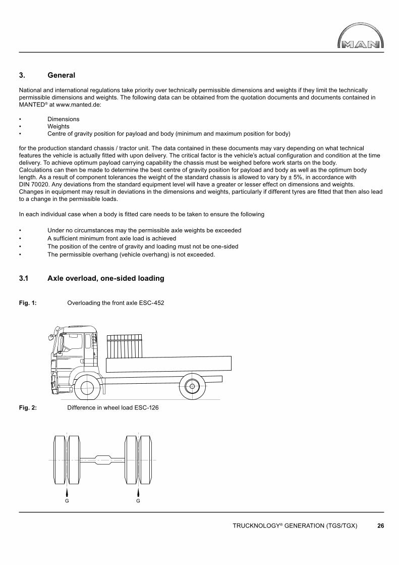
3.1 Axle overload, one-sided loading
Fig. 1: Overloading the front axle ESC-452
Fig. 2: Difference in wheel load ESC-126
TRUCKNOLOGY® GENERATION (TGS/TGX) 27
Formula 1: Difference in wheel load
∆G ≤ 0,05 • Gtat
The body must be designed such that one-sided wheel loads do not occur. Following checks, a maximum wheel load difference of 5% is permitted (where 100% represents the actual axle load and not the permissible axle load).
Example:
Actual axle load Gtat = 11.000 kg
Therefore, the permissible wheel load difference is:
∆G = 0,05 Gtat = 0,05 · 11.000 kg ∆G = 550 kg
This means for example that the wheel load on one side is 5,225 kg and 5,775 kg on the other. The calculated maximum wheel load provides no information on the permissible individual wheel load for the tyres fi tted. Information on this can be found in the technical manuals supplied by the tyre manufacturers.
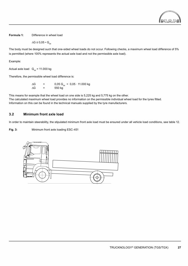
3.2 Minimum front axle load
In order to maintain steerability, the stipulated minimum front axle load must be ensured under all vehicle load conditions, see table 12.
Fig. 3: Minimum front axle loading ESC-451
TRUCKNOLOGY® GENERATION (TGS/TGX) 28
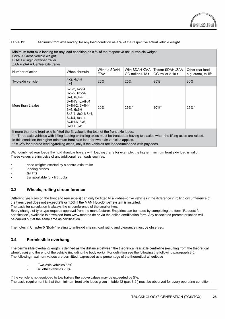
Table 12: Minimum front axle loading for any load condition as a % of the respective actual vehicle weight
Minimum front axle loading for any load condition as a % of the respective actual vehicle weight GVW = Gross vehicle weightSDAH = Rigid drawbar trailerZAA = ZAA = Centre-axle trailer
Number of axles Wheel formula Without SDAH /ZAA
With SDAH /ZAA GG trailer ≤ 18 t
Tridem SDAH /ZAA GG trailer > 18 t
Other rear load e.g. crane, taillift
Two-axle vehicle 4x2, 4x4H 4x4 25% 25% 35% 30%
More than 2 axles
6x2/2, 6x2/46x2-2, 6x2-46x4, 6x4-46x4H/2, 6x4H/46x4H-2, 6x4H-46x6, 6x6H8x2-4, 8x2-6 8x4, 8x4/4, 8x4-48x4H-6, 8x6, 8x6H, 8x8
20% 25%* 30%* 25%*
If more than one front axle is fi tted the % value is the total of the front axle loads.* = Three axle vehicles with lifting leading or trailing axles must be treated as having two axles when the lifting axles are raised. In this condition the higher minimum front axle load for two axle vehicles applies.** = -2% for steered leading/trailing axles, only if the vehicles are loaded/unloaded with payloads.
With combined rear loads like rigid drawbar trailers with loading crane for example, the higher minimum front axle load is valid.These values are inclusive of any additional rear loads such as:
• nose weights exerted by a centre-axle trailer• loading cranes• tail lifts• transportable fork lift trucks.
3.3 Wheels, rolling circumference
Different tyre sizes on the front and rear axle(s) can only be fitted to all-wheel-drive vehicles if the difference in rolling circumference ofthe tyres used does not exceed 2% or 1.5% if the MAN HydroDrive® system is installed. The basis for calculation is always the circumference of the smaller tyre.Every change of tyre type requires approval from the manufacturer. Enquiries can be made by completing the form “Request for certifi cation”, available to download from www.manted.de or via the online certifi cation form. Any associated parameterisation will be carried out at the same time as certifi cation.
The notes in Chapter 5 “Body” relating to anti-skid chains, load rating and clearance must be observed.
3.4 Permissible overhang
The permissible overhang length is defi ned as the distance between the theoretical rear axle centreline (resulting from the theoretical wheelbase) and the end of the vehicle (including the bodywork). For defi nition see the following the following paragraph 3.5.The following maximum values are permitted, expressed as a percentage of the theoretical wheelbase
- Two-axle vehicles 65% - all other vehicles 70%.
If the vehicle is not equipped to tow trailers the above values may be exceeded by 5%. The basic requirement is that the minimum front axle loads given in table 12 (par. 3.2.) must be observed for every operating condition.
Gzul1
ut
Gzul2
l12= lt
Gzul1
ut
Gzul2 Gzul3
l12
lt
l23
TRUCKNOLOGY® GENERATION (TGS/TGX) 29
Theoretical rear axle centreline
Theoretical rear axle centreline
Gpermissible1
Gpermissible1
Gpermissible2
Gpermissible2 Gpermissible3
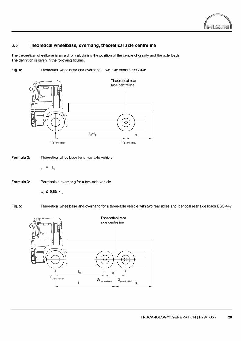
3.5 Theoretical wheelbase, overhang, theoretical axle centreline
The theoretical wheelbase is an aid for calculating the position of the centre of gravity and the axle loads. The defi nition is given in the following fi gures.
Fig. 4: Theoretical wheelbase and overhang – two-axle vehicle ESC-446
Formula 2: Theoretical wheelbase for a two-axle vehicle
lt = l12
Formula 3: Permissible overhang for a two-axle vehicle
Ut ≤ 0,65 • lt
Fig. 5: Theoretical wheelbase and overhang for a three-axle vehicle with two rear axles and identical rear axle loads ESC-447
Gzul1
ut
Gzul2 Gzul3
l12
lt
l23
TRUCKNOLOGY® GENERATION (TGS/TGX) 30
Theoretical rear axle centreline
Gpermissible1 Gpermissible2 Gpermissible3
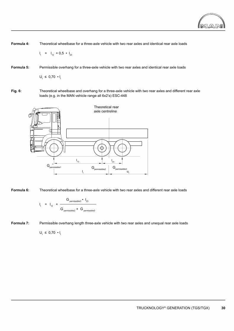
Formula 4: Theoretical wheelbase for a three-axle vehicle with two rear axles and identical rear axle loads
lt = l12 + 0,5 • l23
Formula 5: Permissible overhang for a three-axle vehicle with two rear axles and identical rear axle loads
Ut ≤ 0,70 • lt
Fig. 6: Theoretical wheelbase and overhang for a three-axle vehicle with two rear axles and different rear axle loads (e.g. in the MAN vehicle range all 6x2’s) ESC-448
Formula 6: Theoretical wheelbase for a three-axle vehicle with two rear axles and different rear axle loads
G permissible3 • l23
lt = l12 + G permissible2 + G permissible3
Formula 7: Permissible overhang length three-axle vehicle with two rear axles and unequal rear axle loads
Ut ≤ 0,70 • lt
TRUCKNOLOGY® GENERATION (TGS/TGX) 31
Theoretical rear axle centreline
Theoretical front axle centreline
Gpermissible1
l12 l23
lt Ut
l34
Gpermissible2 Gpermissible3 Gpermissible4
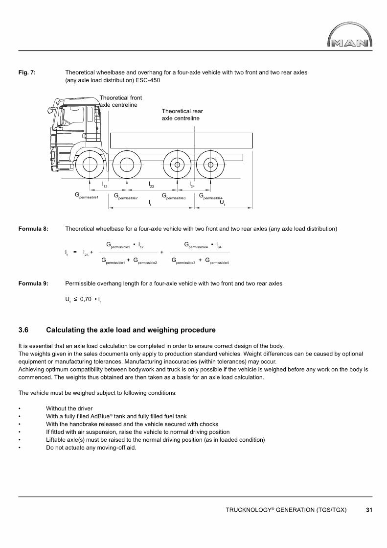
Fig. 7: Theoretical wheelbase and overhang for a four-axle vehicle with two front and two rear axles (any axle load distribution) ESC-450
Formula 8: Theoretical wheelbase for a four-axle vehicle with two front and two rear axles (any axle load distribution)
Gpermissible1 • l12 Gpermissible4 • l34
lt = l23 + + Gpermissible1 + Gpermissible2 Gpermissible3 + Gpermissible4
Formula 9: Permissible overhang length for a four-axle vehicle with two front and two rear axles
Ut ≤ 0,70 • lt
3.6 Calculating the axle load and weighing procedure
It is essential that an axle load calculation be completed in order to ensure correct design of the body.The weights given in the sales documents only apply to production standard vehicles. Weight differences can be caused by optional equipment or manufacturing tolerances. Manufacturing inaccuracies (within tolerances) may occur.Achieving optimum compatibility between bodywork and truck is only possible if the vehicle is weighed before any work on the body is commenced. The weights thus obtained are then taken as a basis for an axle load calculation.
The vehicle must be weighed subject to following conditions:
• Without the driver• With a fully fi lled AdBlue® tank and fully fi lled fuel tank• With the handbrake released and the vehicle secured with chocks• If fi tted with air suspension, raise the vehicle to normal driving position• Liftable axle(s) must be raised to the normal driving position (as in loaded condition)• Do not actuate any moving-off aid.
TRUCKNOLOGY® GENERATION (TGS/TGX) 32
Observe the following sequence when weighing a vehicle (leading or trailing axle relates to the rear axle):
Two-axle vehicles
• 1st axle • 2nd axle • whole vehicle as a check
Three-axle vehicles with two rear axles
• 1st axle• 2nd together with 3rd axle • whole vehicle as a check
Four axle vehicle with two front and two rear axles
• 1st together with 2nd axle • 3rd together with 4th axle• whole vehicle as a check
Four-axle vehicle with one front and three rear axles
• 1st axle • 2nd together with 3rd and 4th axles • whole vehicle as a check.
3.7 Checking and adjustment procedures before and after body has been fitted On the TGS/TGX do not check or adjust:
• ALB settings: No adjustments necessary once bodywork has been fitted• Tachograph ‘MTCO’ – as this has already been calibrated at the factory• Digital tachograph ‘DTCO’ – as this has already been calibrated at the factory.
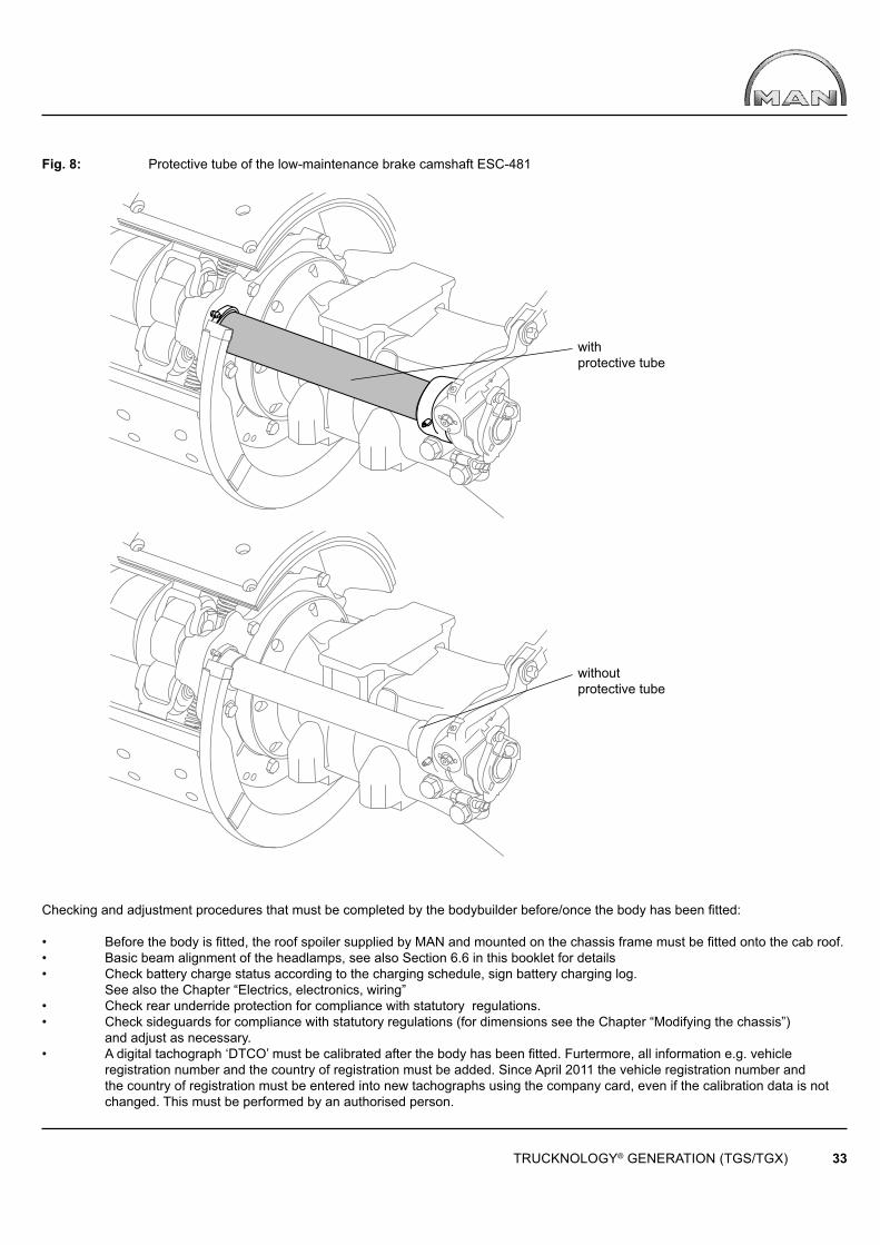
According to EU Directives however, a person authorised to carry out tests must enter the registration number (normally this is not yet assigned when the vehicle leaves the MAN factory). When installing a central lubrication system:Do not connect the lubrication system to the low-maintenance brake camshafts on drive axles fi tted with drum brakes. Drive axles fi tted with drum brakes are installed on all-wheel drive vehicles and on vehicles of medium build height (planetary axles). Low-maintenance brake camshafts can be recognised from their protective tube, see Fig. 8.Lubrication may only be applied every 4 years using special high-temperature grease in accordance with MAN Standard 284.
TRUCKNOLOGY® GENERATION (TGS/TGX) 33
withprotective tube
without protective tube
Fig. 8: Protective tube of the low-maintenance brake camshaft ESC-481
Checking and adjustment procedures that must be completed by the bodybuilder before/once the body has been fitted:
• Before the body is fitted, the roof spoiler supplied by MAN and mounted on the chassis frame must be fitted onto the cab roof.• Basic beam alignment of the headlamps, see also Section 6.6 in this booklet for details• Check battery charge status according to the charging schedule, sign battery charging log. See also the Chapter “Electrics, electronics, wiring”• Check rear underride protection for compliance with statutory regulations.• Check sideguards for compliance with statutory regulations (for dimensions see the Chapter “Modifying the chassis”) and adjust as necessary.• A digital tachograph ‘DTCO’ must be calibrated after the body has been fi tted. Furtermore, all information e.g. vehicle registration number and the country of registration must be added. Since April 2011 the vehicle registration number and the country of registration must be entered into new tachographs using the company card, even if the calibration data is not changed. This must be performed by an authorised person.
TRUCKNOLOGY® GENERATION (TGS/TGX) 34
3.8 Notes on MAN Hydrodrive®
MAN Hydrodrive® is a hydrostatic front axle drive that employs wheel hub motors. The system is selectable and operates in the speed range between 0 and 28 km/h. Vehicles fi tted with Hydrodrive® are legally regarded as off-road vehicles as defi ned by 70/156 EEC (as last amended by 2005/64/EU and 2005/66/EG).
The Hydrodrive® hydraulic circuit is solely approved for the regulated drive of the front axle and may not be used to supply other hydraulic systems. Modifi cations to the Hydrodrive® hydraulic system (including relocating pipework) may only be carried out by specifi cally authorised companies.
In the case of semi-trailer tippers and other bodies where there is a risk of the cargo falling into the area around the oil cooler an oil cooler cover must be fi tted. This is available fi tted ex-works or as a retrofi t solution under the name ‚Protective cover for oil cooler/fan for HydroDrive®’. (Installation no. 81.36000.8134).
4. Modifying the chassis
To provide customers with the products they want, additional components sometimes need to be installed, attached or modifi ed. For uniformity of design and ease of maintenance, we recommend that original MAN components be used as long as these comply with the vehicle’s structural design. To keep maintenance work to a minimum, we recommend the use of components that have the same maintenance intervals as the MAN chassis. Modifi cations to safety-critical components of wheel/axle guides, steering and brakes are not allowed. Existing anti-roll bars may neither be removed nor modifi ed. Installation and/or modifi cation of components frequently requires intervention in the control unit’s CAN architecture (e.g. when extending the EBS electronic braking system). The necessary modifi cations and/or expansion of the vehicle programming are described under the corresponding topic in these guidelines. Such modifi cations may only be undertaken with assistance from the electronics experts at MAN service centres and the programming must be approved by MAN (for address see “Publisher” above). Retrofi tted systems may, under certain circumstances, not be assimila-ted into the vehicles’ on-board Trucknology® systems “Time maintenance system” of “Flexible maintenance system”. For this reason it is not possible to achieve the same degree of maintenance convenience as is possible with original equipment.
4.1 Frame material
When carrying out modifications to the chassis longitudinal and cross-members only use of the original frame material S500MC (QStE 500TM) is approved.Exception: For profile 33 and 42, the frame is made of S420MC = QStE420TM.For profi le 43, the frame is made of LNE500 to Brasilian standard NBR 6656:2008
Table 13: Steel for TGS/TGX frame
Material number
Previous material
designation
Previous standard
σ0,2N/mm2
σBN/mm2
New material designation
New standard
Profi le codes as per table 14
1.0980 QStE420TM SEW 092 ≥ 420 480-620 S420MC DIN EN 10149-2 33 1.0984 QStE500TM SEW 092 ≥ 500 550-700 S500MC DIN EN 10149-2 31 32 34
500 560-700 LNE500 NBR 6656:2008 43
For subframe longitudinal and cross-members only steels with a yield point of σ0,2 ≥ 350 N/mm2 may be used. For additional details on subframes see the Subframe Chapter 5.3.3.
Depending on the model, the following longitudinal frame members are used.
Bo
Bu ex
h
H
R
t
e y
TRUCKNOLOGY® GENERATION (TGS/TGX) 35
Surface centre of gravity S
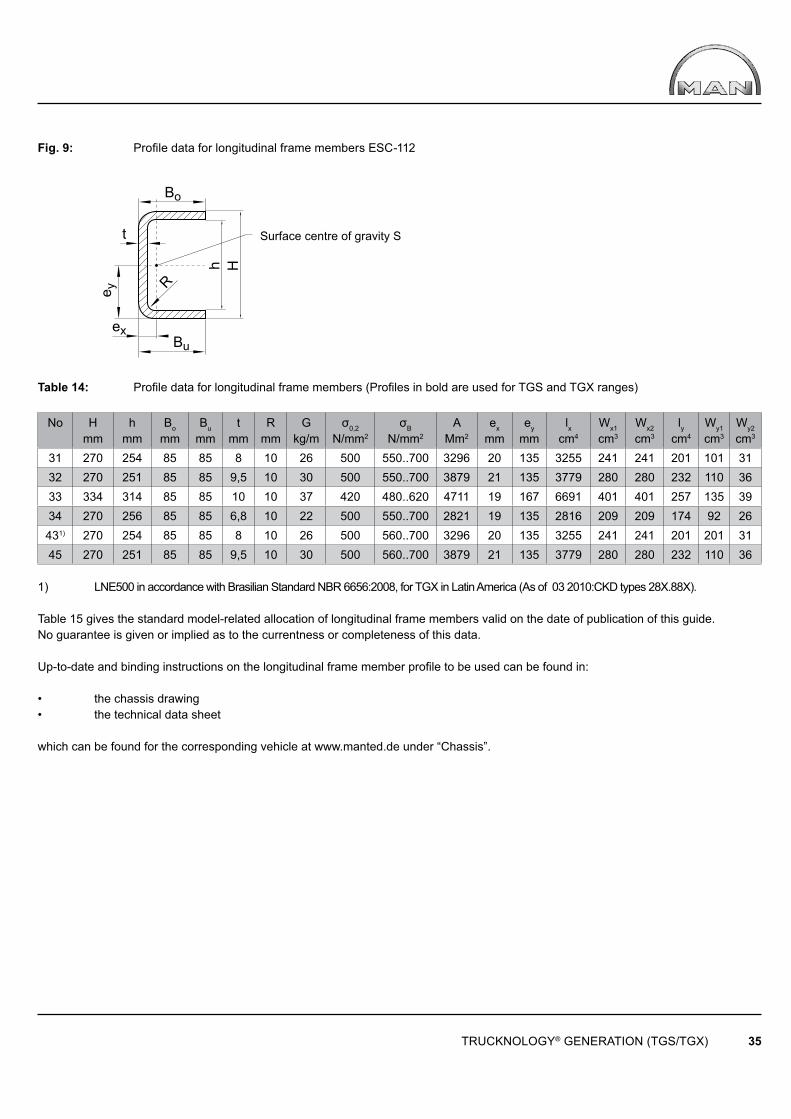
Fig. 9: Profi le data for longitudinal frame members ESC-112
Table 14: Profile data for longitudinal frame members (Profi les in bold are used for TGS and TGX ranges)
No Hmm
hmm
Bo
mmBu
mmt
mmR
mmG
kg/mσ0,2
N/mm2
σB
N/mm2
AMm2
ex
mmey
mmlx
cm4
Wx1
cm3
Wx2
cm3
lycm4
Wy1
cm3
Wy2
cm3
31 270 254 85 85 8 10 26 500 550..700 3296 20 135 3255 241 241 201 101 3132 270 251 85 85 9,5 10 30 500 550..700 3879 21 135 3779 280 280 232 110 3633 334 314 85 85 10 10 37 420 480..620 4711 19 167 6691 401 401 257 135 3934 270 256 85 85 6,8 10 22 500 550..700 2821 19 135 2816 209 209 174 92 26431) 270 254 85 85 8 10 26 500 560..700 3296 20 135 3255 241 241 201 201 3145 270 251 85 85 9,5 10 30 500 560..700 3879 21 135 3779 280 280 232 110 36
1) LNE500 in accordance with Brasilian Standard NBR 6656:2008, for TGX in Latin America (As of 03 2010:CKD types 28X.88X).
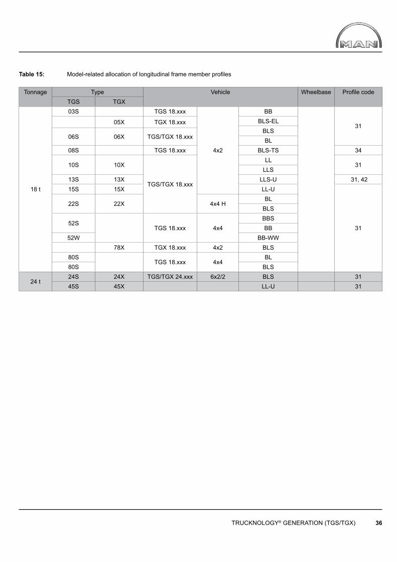
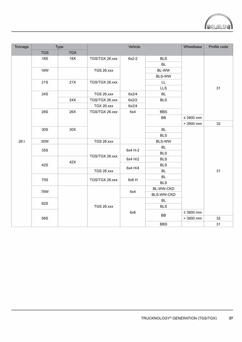
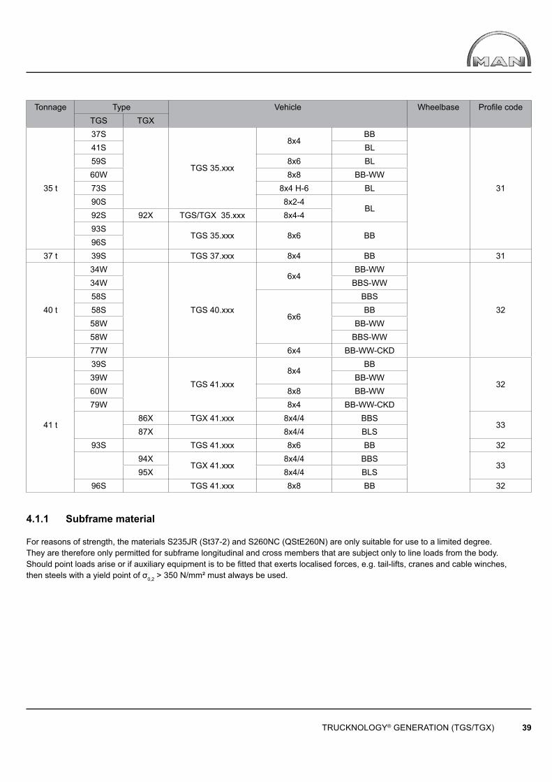
Table 15 gives the standard model-related allocation of longitudinal frame members valid on the date of publication of this guide.No guarantee is given or implied as to the currentness or completeness of this data.
Up-to-date and binding instructions on the longitudinal frame member profile to be used can be found in:
• the chassis drawing• the technical data sheet
which can be found for the corresponding vehicle at www.manted.de under “Chassis”.
TRUCKNOLOGY® GENERATION (TGS/TGX) 36
Table 15: Model-related allocation of longitudinal frame member profi les
Tonnage Type Vehicle Wheelbase Profi le codeTGS TGX
18 t
03S TGS 18.xxx
4x2
BB
31 05X TGX 18.xxx BLS-ELBLS
06S 06X TGS/TGX 18.xxx BL08S TGS 18.xxx BLS-TS 34
10S 10X
TGS/TGX 18.xxx
LL31
LLS13S 13X LLS-U 31, 4215S 15X LL-U
31
22S 22X 4x4 HBL
BLS
52S TGS 18.xxx 4x4
BBSBB
52W BB-WW 78X TGX 18.xxx 4x2 BLS
80S TGS 18.xxx 4x4
BL80S BLS
24 t24S 24X TGS/TGX 24.xxx 6x2/2 BLS 3145S 45X LL-U 31
TRUCKNOLOGY® GENERATION (TGS/TGX) 37
Tonnage Type Vehicle Wheelbase Profi le codeTGS TGX
26 t
18S 18X TGS/TGX 26.xxx 6x2-2 BLS
31
BL18W TGS 26.xxx BL-WW
BLS-WW21S 21X TGS/TGX 26.xxx LL
LLS24S TGS 26.xxx 6x2/4 BL
24X TGS/TGX 26.xxx 6x2/2 BLSTGX 26.xxx 6x2/4
26S 26X TGS/TGX 26.xxx 6x4 BBSBB ≤ 3900 mm
> 3900 mm 3230S 30X BL
31
BLS30W TGS 26.xxx BLS-WW
35S TGS/TGX 26.xxx
6x4 H-2BL
BLS
42S42X
6x4 H/2 BLS
6x4 H/4BLS
TGS 26.xxx BL
70S TGS/TGX 26.xxx 6x6 HBL
BLS
78W
TGS 26.xxx
6x4BL-WW-CKD
BLS-WW-CKD
82S
6x6
BLBLS
56SBB
≤ 3900 mm> 3900 mm 32
BBS 31

TRUCKNOLOGY® GENERATION (TGS/TGX) 38
Tonnage Type Vehicle Wheelbase Profi le codeTGS TGX
28t
19W TGS 28.xxx
6x2-2BL-WW
31BLS-WW
28X TGX 28.xxx 6x4 BBS-CKD 43, 4571S
TGS 28.xxx
6x4 H-4 BL
3173W 6x2-2BLS-WW-CKDBL-WW-CKD
74S 6x2-4 BL 88X TGX 28.xxx
6x2-2BLS-CKD 45
89S TGS 28.xxx
BL
31BLS
84S 6x4-4 BL
89X TGX 28.xxx 6x2-2BLS
33t
26S 26X TGS/TGX 33.xxx
6x4
BBS 31
BB ≤ 3900 mm> 3900 mm 32
26W TGS 33.xxxBB-WW ≤ 3900 mm 31
≥ 3900 mm 32BBS-WW
31
30S 30X TGS/TGX 33.xxxBL
BLS30W
TGS 33.xxx
BLS-WW
47S 6x6 HBB
BBS
56W 6x6BBS-WWBB-WW
76W6x4
BBS-WW-CKDBB-WW-CKD ≤ 3900 mm
≥ 3900 mm 32
79X TGX 33BLS
31BL
82S
TGS 33.xxx 6x6
BL ≤ 4200 mm≥ 4200 mm 32
BLS 31
56SBB ≤ 3900 mm 31
> 3900 mm 32BBS 31
TRUCKNOLOGY® GENERATION (TGS/TGX) 39
Tonnage Type Vehicle Wheelbase Profi le codeTGS TGX
35 t
37S
TGS 35.xxx
8x4BB
31
41S BL59S 8x6 BL60W 8x8 BB-WW73S 8x4 H-6 BL90S 8x2-4
BL92S 92X TGS/TGX 35.xxx 8x4-493S
TGS 35.xxx 8x6 BB96S
37 t 39S TGS 37.xxx 8x4 BB 31
40 t
34W
TGS 40.xxx
6x4BB-WW
32
34W BBS-WW58S
6x6
BBS58S BB58W BB-WW58W BBS-WW77W 6x4 BB-WW-CKD
41 t
39S
TGS 41.xxx8x4
BB
3239W BB-WW60W 8x8 BB-WW79W 8x4 BB-WW-CKD
86X TGX 41.xxx 8x4/4 BBS
3387X 8x4/4 BLS
93S TGS 41.xxx 8x6 BB 32
94X
TGX 41.xxx8x4/4 BBS
3395X 8x4/4 BLS
96S TGS 41.xxx 8x8 BB 32
4.1.1 Subframe material
For reasons of strength, the materials S235JR (St37-2) and S260NC (QStE260N) are only suitable for use to a limited degree.They are therefore only permitted for subframe longitudinal and cross members that are subject only to line loads from the body. Should point loads arise or if auxiliary equipment is to be fitted that exerts localised forces, e.g. tail-lifts, cranes and cable winches, then steels with a yield point of σ0,2 > 350 N/mm² must always be used.
TRUCKNOLOGY® GENERATION (TGS/TGX) 40
4.2 Corrosion protection
Surface and corrosion protection affects the service life and appearance of the product. In general, the quality of the coatings on body components should be equal to that of the chassis.
In order to fulfi l this requirement, the MAN Works Standard M 3297 “Corrosion protection and coating systems for non-MAN bodies” is binding for bodies that are ordered by MAN. If the customer commissions the body, this standard becomes a recommendation only. Should the standard not be observed, MAN provides no guarantee for any consequences.MAN-works standards may be sourced via www.normen.man-nutzfahrzeuge.de, registration required. For corrosion protection of the body see chapter 5.2.
Series production MAN chassis are coated with environmentally friendly, water-based 2-component chassis top-coat paints at approx. 80°C. To guarantee uniform coating, the following coating structure is required for all metal component assemblies on the body and subframe:
• Bare metal or blasted component surface (SA 2.5)• Primer coat: 2-component epoxy primer, permitted in accordance with MAN standard M 3162-C if possible, cathodic dip painting to MAN works standard M 3078-2, with zinc phosphate pre-treatment• Top coat: 2-component top-coat paint to MAN works standard M 3094, preferably water-based; if there are no facilities for this, then solvent-based paint is also permitted. (www.normen.man-nutzfahrzeuge.de, registration required).
See the relevant paint manufacturer’s data sheets for information on tolerances for drying and curing times and temperatures. When selecting and combining materials the compatibility of the different metals (e.g. aluminium and steel) must be taken into consideration as must the effects of the ‘electrochemical series’ (cause of contact corrosion).
After all work on the chassis has been completed:
• Remove any drilling swarf• Remove burrs from the edges• Apply wax preservative to any cavities
Mechanical connections (e.g. bolts, nuts, washers, pins) that have not been painted over must be given optimum corrosion protection.To prevent the occurrence of salt corrosion whilst the vehicle is stationary during the body-building phase, all chassis must be washed with clean water to remove any salt residues as soon as they arrive at the body manufacturer’s premises.
4.3 Drill holes, riveted joints and screw connections on the frame
If possible, use the holes already drilled in the frame. No drilling should be carried out in the fl anges of the longitudinal frame member profi les, i.e. in the upper and lower fl anges (see Fig. 10). The only exception to this is at the rear end of the frame, outside the area of all the parts fi tted to the frame that have a load-bearing function for the rearmost axle (see Fig. 11).This also applies to the subframe.
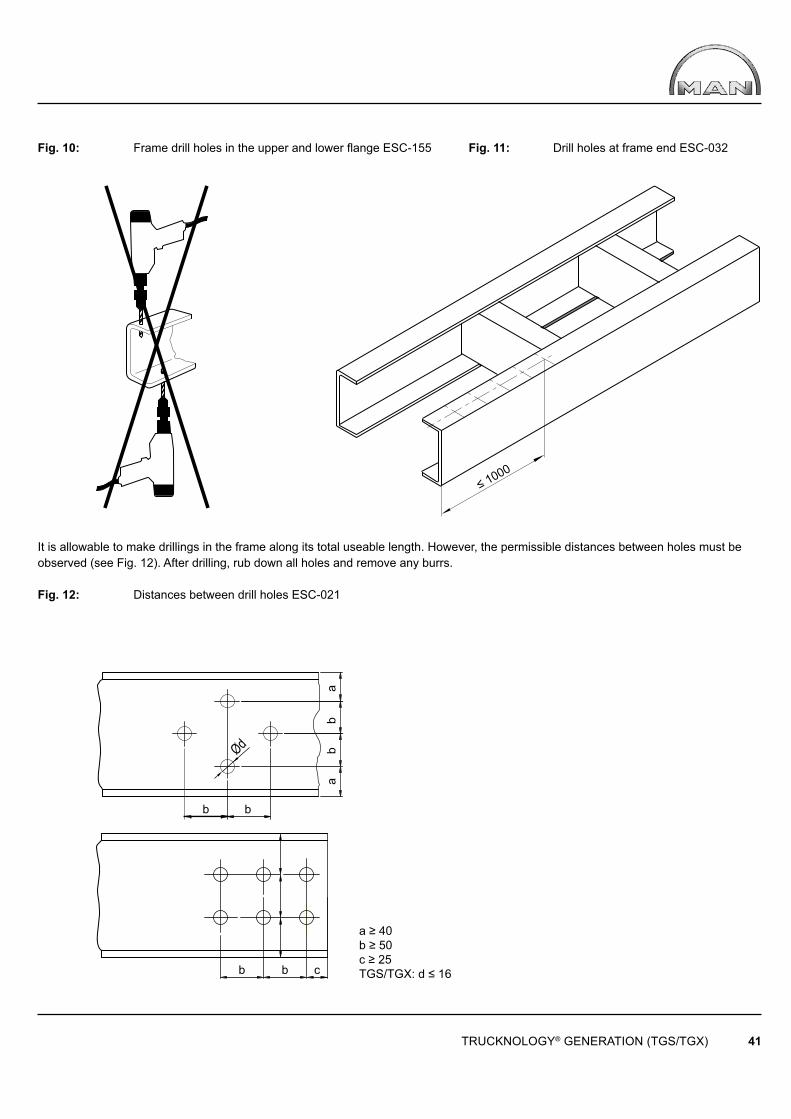
Ød
b b
b b
b b
a a
c
TRUCKNOLOGY® GENERATION (TGS/TGX) 41
a ≥ 40b ≥ 50c ≥ 25TGS/TGX: d ≤ 16
Fig. 10: Frame drill holes in the upper and lower fl ange ESC-155 Fig. 11: Drill holes at frame end ESC-032
It is allowable to make drillings in the frame along its total useable length. However, the permissible distances between holes must be observed (see Fig. 12). After drilling, rub down all holes and remove any burrs.
Fig. 12: Distances between drill holes ESC-021
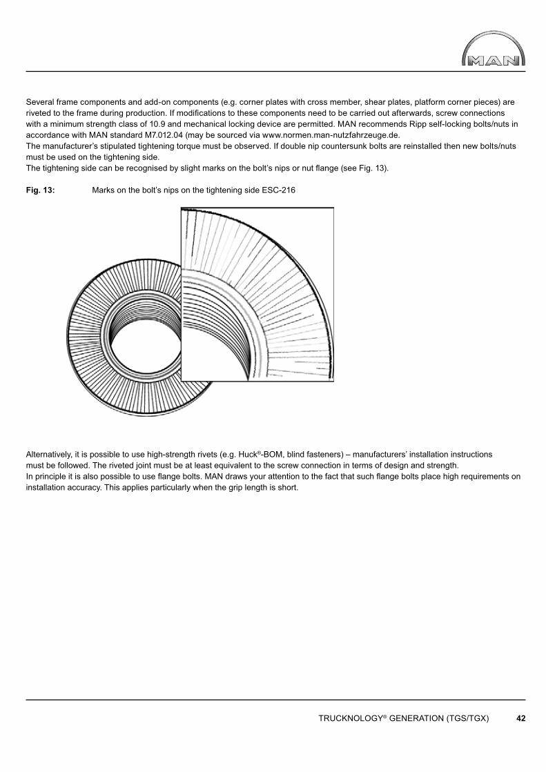
TRUCKNOLOGY® GENERATION (TGS/TGX) 42
Several frame components and add-on components (e.g. corner plates with cross member, shear plates, platform corner pieces) are riveted to the frame during production. If modifi cations to these components need to be carried out afterwards, screw connections with a minimum strength class of 10.9 and mechanical locking device are permitted. MAN recommends Ripp self-locking bolts/nuts in accordance with MAN standard M7.012.04 (may be sourced via www.normen.man-nutzfahrzeuge.de.The manufacturer’s stipulated tightening torque must be observed. If double nip countersunk bolts are reinstalled then new bolts/nuts must be used on the tightening side. The tightening side can be recognised by slight marks on the bolt’s nips or nut fl ange (see Fig. 13).
Fig. 13: Marks on the bolt’s nips on the tightening side ESC-216
Alternatively, it is possible to use high-strength rivets (e.g. Huck®-BOM, blind fasteners) – manufacturers’ installation instructions must be followed. The riveted joint must be at least equivalent to the screw connection in terms of design and strength.In principle it is also possible to use fl ange bolts. MAN draws your attention to the fact that such fl ange bolts place high requirements on installation accuracy. This applies particularly when the grip length is short.
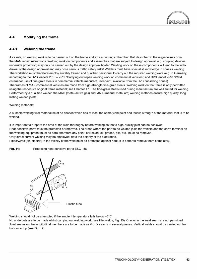
TRUCKNOLOGY® GENERATION (TGS/TGX) 43
Plastic tube
4.4 Modifying the frame
4.4.1 Welding the frame
As a rule, no welding work is to be carried out on the frame and axle mountings other than that described in these guidelines or inthe MAN repair instructions. Welding work on components and assemblies that are subject to design approval (e.g. coupling devices, underride protection) may only be carried out by the design approval holder. Welding work on these components will lead to the with-drawal of the design approval and may pose serious traffic safety risks! Welders must have specialist knowledge in chassis welding. The workshop must therefore employ suitably trained and qualified personnel to carry out the required welding work (e.g. in Germany, according to the DVS leaflets 2510 – 2512 “Carrying out repair welding work on commercial vehicles”, and DVS leaflet 2518 “Weld criteria for use of fi ne grain steels in commercial vehicle manufacture/repair “, available from the DVS publishing house).The frames of MAN commercial vehicles are made from high-strength fine-grain steels. Welding work on the frame is only permittedusing the respective original frame material; see Chapter 4.1. The fine-grain steels used during manufacture are well suited for welding. Performed by a qualified welder, the MAG (metal-active gas) and MMA (manual metal arc) welding methods ensure high quality, long lasting welded joints.
Welding materials:
A suitable welding fi ller material must be chosen which has at least the same yield point and tensile strength of the material that is to be welded.
It is important to prepare the area of the weld thoroughly before welding so that a high-quality joint can be achieved. Heat-sensitive parts must be protected or removed. The areas where the part to be welded joins the vehicle and the earth terminal on the welding equipment must be bare; therefore any paint, corrosion, oil, grease, dirt, etc., must be removed. Only direct current welding may be employed; note the polarity of the electrodes.Pipes/wires (air, electric) in the vicinity of the weld must be protected against heat. It is better to remove them completely.
Fig. 14: Protecting heat-sensitive parts ESC-156
Welding should not be attempted if the ambient temperature falls below +5°C.No undercuts are to be made whilst carrying out welding work (see fi llet welds, Fig. 15). Cracks in the weld seam are not permitted. Joint seams on the longitudinal members are to be made as V or X seams in several passes. Vertical welds should be carried out from bottom to top (see Fig. 17).
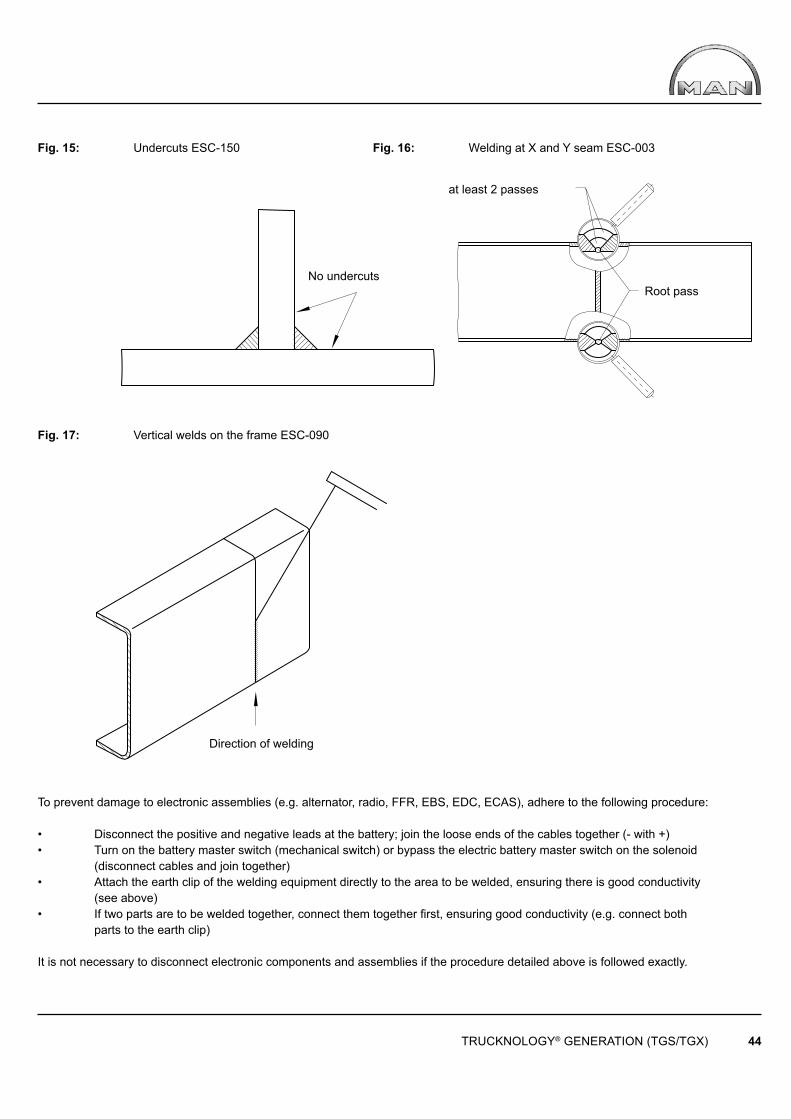
TRUCKNOLOGY® GENERATION (TGS/TGX) 44
at least 2 passes
Root passNo undercuts
Direction of welding
Fig. 15: Undercuts ESC-150 Fig. 16: Welding at X and Y seam ESC-003
Fig. 17: Vertical welds on the frame ESC-090
To prevent damage to electronic assemblies (e.g. alternator, radio, FFR, EBS, EDC, ECAS), adhere to the following procedure:
• Disconnect the positive and negative leads at the battery; join the loose ends of the cables together (- with +)• Turn on the battery master switch (mechanical switch) or bypass the electric battery master switch on the solenoid (disconnect cables and join together)• Attach the earth clip of the welding equipment directly to the area to be welded, ensuring there is good conductivity (see above)• If two parts are to be welded together, connect them together fi rst, ensuring good conductivity (e.g. connect both parts to the earth clip)
It is not necessary to disconnect electronic components and assemblies if the procedure detailed above is followed exactly.
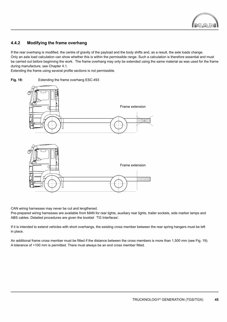
TRUCKNOLOGY® GENERATION (TGS/TGX) 45
Frame extension
Frame extension
4.4.2 Modifying the frame overhang
If the rear overhang is modifi ed, the centre of gravity of the payload and the body shifts and, as a result, the axle loads change. Only an axle load calculation can show whether this is within the permissible range. Such a calculation is therefore essential and must be carried out before beginning the work. The frame overhang may only be extended using the same material as was used for the frame during manufacture, see Chapter 4.1.Extending the frame using several profi le sections is not permissible.
Fig. 18: Extending the frame overhang ESC-493
CAN wiring harnesses may never be cut and lengthened.Pre-prepared wiring harnesses are available from MAN for rear lights, auxiliary rear lights, trailer sockets, side marker lamps and ABS cables. Detailed procedures are given the booklet ‘TG Interfaces’.
If it is intended to extend vehicles with short overhangs, the existing cross member between the rear spring hangers must be left in place.
An additional frame cross member must be fi tted if the distance between the cross members is more than 1,500 mm (see Fig. 19). A tolerance of +100 mm is permitted. There must always be an end cross member fi tted.

TRUCKNOLOGY® GENERATION (TGS/TGX) 46
Fig. 19: Max. distance between frame cross members ESC-092
If a frame overhang is shortened as far as the axle guide or suspension (e.g. rear spring hanger, stabiliser bracket) the cross members in this area (normally tubular cross-members) must either remain in place or be replaced with suitable original MAN end cross members (see Fig. 20).
Fig. 20: Frame end of a tractor unit ESC-503
4.4.3 Modifi cations to the wheelbase
Every change of wheelbase requires approval from the manufacturer. Enquiries can be made by completing the form “A1.3 Request of confi rmations”, available to download from www.manted.de or via the online certifi cation form. The associated parameterisation of the wheelbase and – if changed – the frame overhang, will be carried out at the same time as certifi cation.Technical design specifi cations applicable to steering (in particular 70/311 EEC, last amended by 2004/09/24) mean that, depending upon the number and type of steered axles, wheelbase, tyres axle loads and permissible gross weight, chassis of the TGS/TGX range are fi tted with different steering wheels (diameter), steering gear (range of ratios) and steering oil piping (cooling coils). Therefore, when considering wheelbase extensions the MAN (for address see “Publisher” above) should always be fi rst consulted as to whether the planned change to the wheelbase will require other steering component modifi cations. Parameterisation of the wheelbase modifi cation (see next paragraph) is only possible if the correct components have been installed. MAN shall not be liable for errors, made as a result of late consultations, that lead to increased cost. In addition, before commencing any work, an application must be made to the MAN repair shop for a conversion data fi le (vehicle parameterisation) quoting the new wheelbase. Parameterisation is carried out using the MAN-cats® diagnosis system.
Modifi cations to the wheelbase can be made by:
• Moving the entire rear axle assembly• Disconnecting the longitudinal frame members and inserting or removing a section of frame.
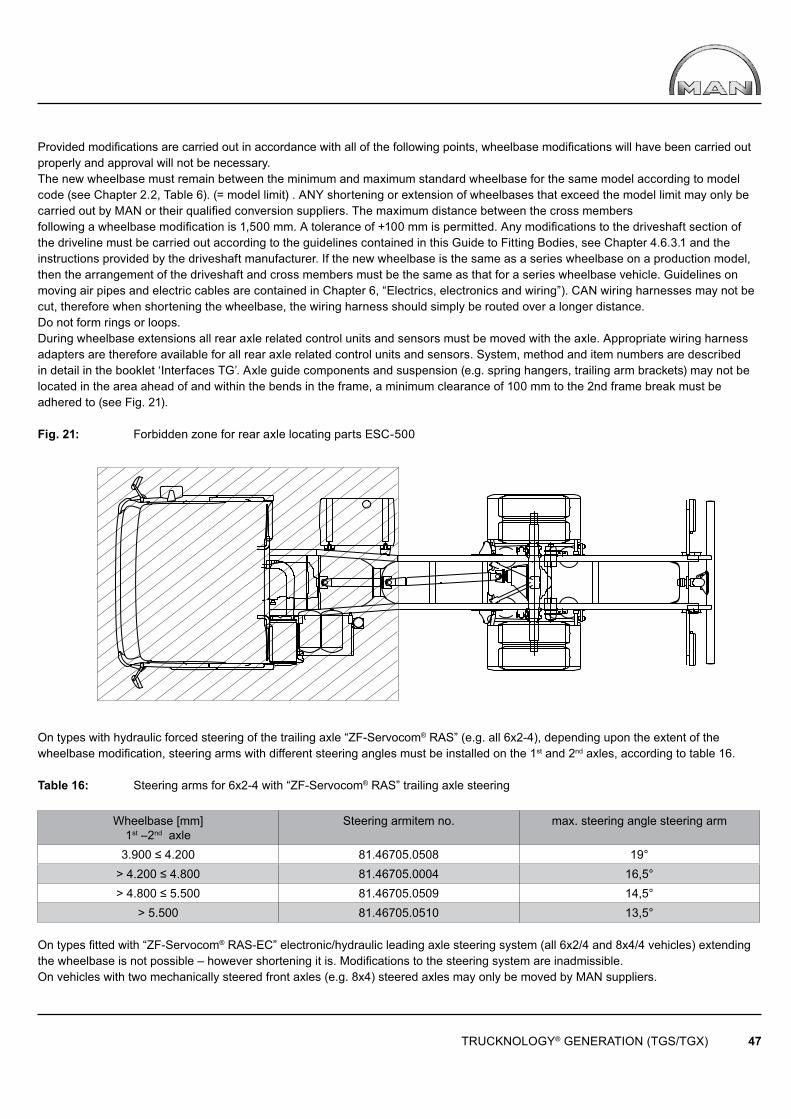
TRUCKNOLOGY® GENERATION (TGS/TGX) 47
Provided modifi cations are carried out in accordance with all of the following points, wheelbase modifi cations will have been carried out properly and approval will not be necessary.The new wheelbase must remain between the minimum and maximum standard wheelbase for the same model according to modelcode (see Chapter 2.2, Table 6). (= model limit) . ANY shortening or extension of wheelbases that exceed the model limit may only be carried out by MAN or their qualifi ed conversion suppliers. The maximum distance between the cross members following a wheelbase modification is 1,500 mm. A tolerance of +100 mm is permitted. Any modifications to the driveshaft section of the driveline must be carried out according to the guidelines contained in this Guide to Fitting Bodies, see Chapter 4.6.3.1 and the instructions provided by the driveshaft manufacturer. If the new wheelbase is the same as a series wheelbase on a production model, then the arrangement of the driveshaft and cross members must be the same as that for a series wheelbase vehicle. Guidelines on moving air pipes and electric cables are contained in Chapter 6, “Electrics, electronics and wiring”). CAN wiring harnesses may not be cut, therefore when shortening the wheelbase, the wiring harness should simply be routed over a longer distance. Do not form rings or loops.During wheelbase extensions all rear axle related control units and sensors must be moved with the axle. Appropriate wiring harness adapters are therefore available for all rear axle related control units and sensors. System, method and item numbers are described in detail in the booklet ‘Interfaces TG’. Axle guide components and suspension (e.g. spring hangers, trailing arm brackets) may not be located in the area ahead of and within the bends in the frame, a minimum clearance of 100 mm to the 2nd frame break must beadhered to (see Fig. 21).
Fig. 21: Forbidden zone for rear axle locating parts ESC-500
On types with hydraulic forced steering of the trailing axle “ZF-Servocom® RAS” (e.g. all 6x2-4), depending upon the extent of the wheelbase modifi cation, steering arms with different steering angles must be installed on the 1st and 2nd axles, according to table 16.
Table 16: Steering arms for 6x2-4 with “ZF-Servocom® RAS” trailing axle steering
Wheelbase [mm]1st –2nd axle
Steering armitem no. max. steering angle steering arm
3.900 ≤ 4.200 81.46705.0508 19°> 4.200 ≤ 4.800 81.46705.0004 16,5°> 4.800 ≤ 5.500 81.46705.0509 14,5°
> 5.500 81.46705.0510 13,5° On types fi tted with “ZF-Servocom® RAS-EC” electronic/hydraulic leading axle steering system (all 6x2/4 and 8x4/4 vehicles) extending the wheelbase is not possible – however shortening it is. Modifi cations to the steering system are inadmissible.On vehicles with two mechanically steered front axles (e.g. 8x4) steered axles may only be moved by MAN suppliers.
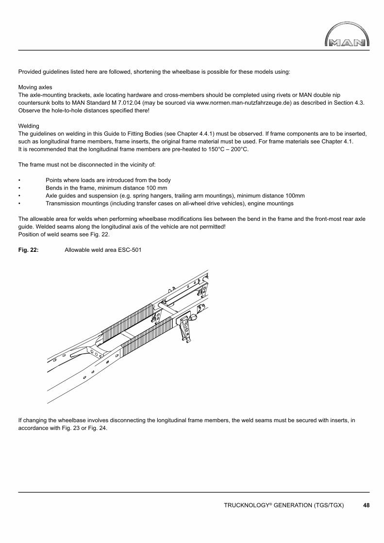
TRUCKNOLOGY® GENERATION (TGS/TGX) 48
Provided guidelines listed here are followed, shortening the wheelbase is possible for these models using:
Moving axlesThe axle-mounting brackets, axle locating hardware and cross-members should be completed using rivets or MAN double nip countersunk bolts to MAN Standard M 7.012.04 (may be sourced via www.normen.man-nutzfahrzeuge.de) as described in Section 4.3.Observe the hole-to-hole distances specifi ed there!
WeldingThe guidelines on welding in this Guide to Fitting Bodies (see Chapter 4.4.1) must be observed. If frame components are to be inserted, such as longitudinal frame members, frame inserts, the original frame material must be used. For frame materials see Chapter 4.1. It is recommended that the longitudinal frame members are pre-heated to 150°C – 200°C.
The frame must not be disconnected in the vicinity of:
• Points where loads are introduced from the body• Bends in the frame, minimum distance 100 mm• Axle guides and suspension (e.g. spring hangers, trailing arm mountings), minimum distance 100mm • Transmission mountings (including transfer cases on all-wheel drive vehicles), engine mountings
The allowable area for welds when performing wheelbase modifi cations lies between the bend in the frame and the front-most rear axle guide. Welded seams along the longitudinal axis of the vehicle are not permitted!Position of weld seams see Fig. 22.
Fig. 22: Allowable weld area ESC-501
If changing the wheelbase involves disconnecting the longitudinal frame members, the weld seams must be secured with inserts, in accordance with Fig. 23 or Fig. 24.
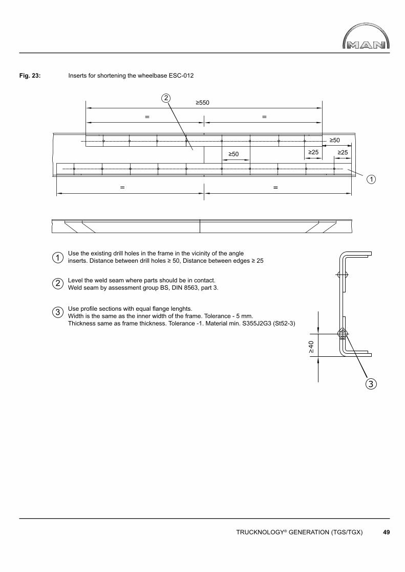
≥550
= =
2
≥50
≥50
≥25 ≥25
1 = =
1
2
3
3
≥40
TRUCKNOLOGY® GENERATION (TGS/TGX) 49
Use the existing drill holes in the frame in the vicinity of the angleinserts. Distance between drill holes ≥ 50, Distance between edges ≥ 25
Level the weld seam where parts should be in contact. Weld seam by assessment group BS, DIN 8563, part 3.
Use profi le sections with equal fl ange lenghts. Width is the same as the inner width of the frame. Tolerance - 5 mm. Thickness same as frame thickness. Tolerance -1. Material min. S355J2G3 (St52-3)
Fig. 23: Inserts for shortening the wheelbase ESC-012
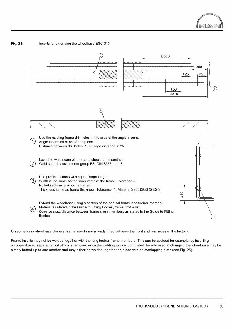
2
1
4
3
≥300
≥50
≥50
≥25 ≥25
≥375
≥40
1
2
3
4
TRUCKNOLOGY® GENERATION (TGS/TGX) 50
Use the existing frame drill holes in the area of the angle inserts. Angle inserts must be of one piece. Distance between drill holes ≥ 50, edge distance ≥ 25
Level the weld seam where parts should be in contact. Weld seam by assesment group BS, DIN 8563, part 3.
Use profi le sections with equal fl ange lengths. Width is the same as the inner width of the frame. Tolerance -5. Rolled sections are not permitted. Thickness same as frame thickness. Tolerance -1. Material S355J3G3 (St52-3)
Extend the wheelbase using a section of the original frame longitudinal member. Material as stated in the Guide to Fitting Bodies, frame profi le list. Observe max. distance between frame cross members as stated in the Guide to Fitting Bodies.
Fig. 24: Inserts for extending the wheelbase ESC-013
On some long-wheelbase chassis, frame inserts are already fi tted between the front and rear axles at the factory.
Frame inserts may not be welded together with the longitudinal frame members. This can be avoided for example, by inserting a copper-based separating foil which is removed once the welding work is completed. Inserts used in changing the wheelbase may be simply butted-up to one another and may either be welded together or joined with an overlapping plate (see Fig. 25).
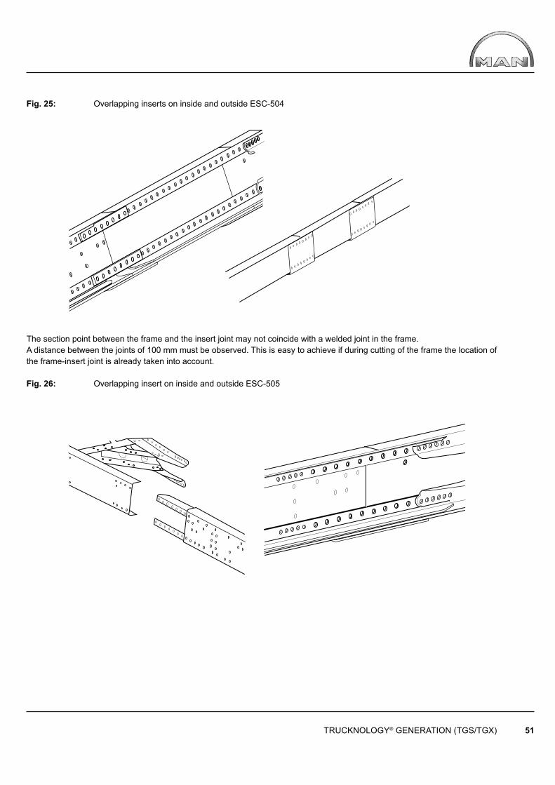
TRUCKNOLOGY® GENERATION (TGS/TGX) 51
Fig. 25: Overlapping inserts on inside and outside ESC-504
The section point between the frame and the insert joint may not coincide with a welded joint in the frame. A distance between the joints of 100 mm must be observed. This is easy to achieve if during cutting of the frame the location of the frame-insert joint is already taken into account.
Fig. 26: Overlapping insert on inside and outside ESC-505
TRUCKNOLOGY® GENERATION (TGS/TGX) 52
4.5 Retrofi tting additional equipment add-on components or accessories
The manufacturer of an assembly, add-on component or accessory must co-ordinate the installation with MAN. Retrofi t installation of components frequently requires intervention in the control unit’s CAN architecture .Such work always requires modifi cation of the vehicle parameterisation. Retrofi tted systems may, under certain circumstances, not be assimilated into the vehicles’ on-board Trucknology® systems “Time maintenance system” of “Flexible maintenance system”. For this reason it is not possible to achieve the same degree of maintenance convenience as is possible with original equipment.Subsequent modifi cation or expansion of the vehicle parameterisation can only be carried out with the help of the electronics specialists at MAN service centres with subsequent approval by MAN. As a result, retrofi t installation of components must be agreed with MAN (for address see “Publisher” above) at the planning stage. MAN will fi rst check to see if it is actually possible to carry out the planned work. For the approval procedure it is essential therefore, that full and verifi able documentation be provided.Under no circumstances does MAN accept responsibility for the design or for the consequences of non-approved retrofi tted equipment. The conditions stated in this Guide and in the approvals must be observed. Approvals, reports and clearance certifi cates that have been compiled by third parties (e.g. test and inspection authorities) do not automatically mean that MAN will also issue approval. MAN reserves the right to refuse approval even though third parties may have issued clearance certifi cates.
Unless otherwise agreed, approval only refers to the actual installation of the equipment. Approval does not mean that MAN has checked the entire system with regard to strength, vehicle handling etc., and has accepted responsibility for warranty of products. The responsibility for this lies with the company carrying out the work. Retrofi tting of equipment may change the vehicle’s technical data. The equipment manufacturer and/or the dealer / importer is responsible for determining and issuing this new data.
4.5.1 Retrofi tting additional or larger fuel tanks after factory delivery
Fuel is taxed at different rates – even within the EU. If larger or additional fuel tanks are fi tted after the vehicle has been delivered from the manufacturer‘s factory then the additional tank volume becomes subject to the mineral oil excise duty applicable in the country into which it is being imported upon crossing the border. Only fuel that is carried in the so-called „standard tanks“ (plus fuel carried in reserve fuel canisters up to a maximum quantity of 20 litres) is free of duty. Standard tanks are the fuel tanks fi tted to the vehicle when it was delivered from the factory and not fuel tanks added at a later time by a body builder or workshop for example.
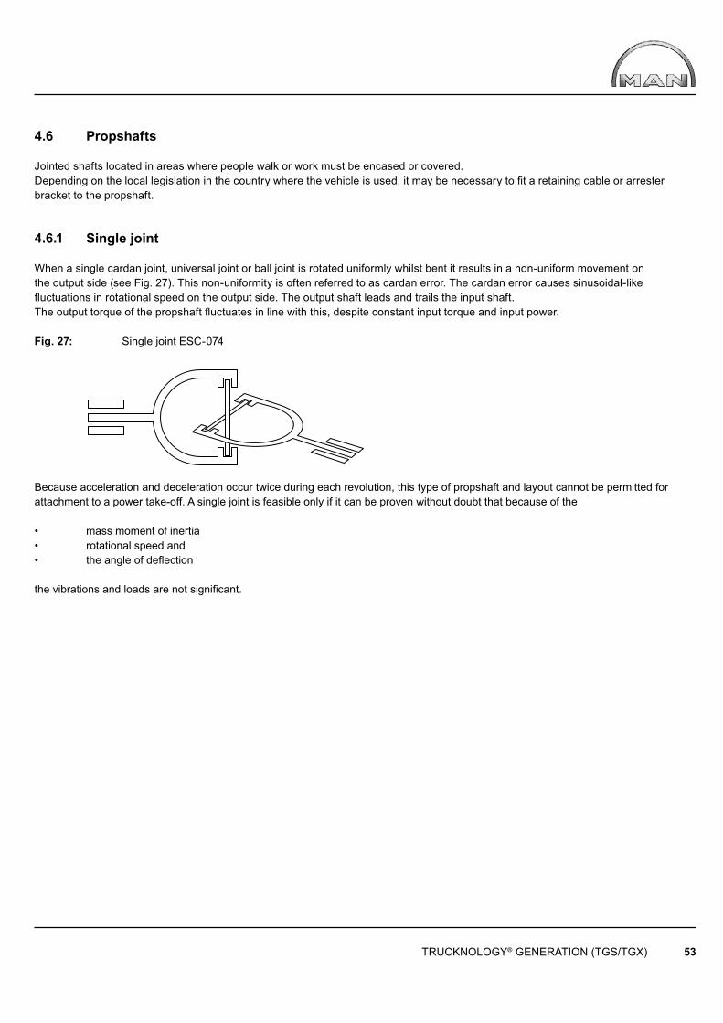
TRUCKNOLOGY® GENERATION (TGS/TGX) 53
4.6 Propshafts
Jointed shafts located in areas where people walk or work must be encased or covered. Depending on the local legislation in the country where the vehicle is used, it may be necessary to fi t a retaining cable or arrester bracket to the propshaft.
4.6.1 Single joint
When a single cardan joint, universal joint or ball joint is rotated uniformly whilst bent it results in a non-uniform movement on the output side (see Fig. 27). This non-uniformity is often referred to as cardan error. The cardan error causes sinusoidal-like fl uctuations in rotational speed on the output side. The output shaft leads and trails the input shaft. The output torque of the propshaft fl uctuates in line with this, despite constant input torque and input power.
Fig. 27: Single joint ESC-074
Because acceleration and deceleration occur twice during each revolution, this type of propshaft and layout cannot be permitted for attachment to a power take-off. A single joint is feasible only if it can be proven without doubt that because of the
• mass moment of inertia• rotational speed and• the angle of defl ection
the vibrations and loads are not signifi cant.
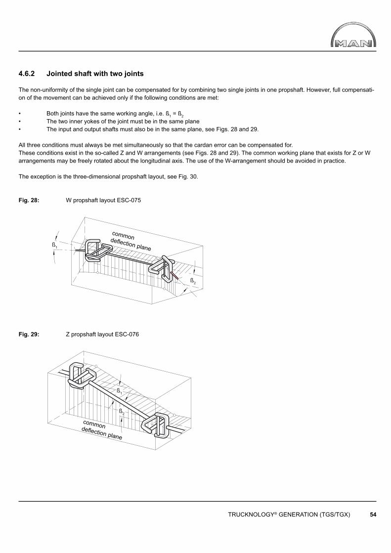
ß1
ß2
ß1
ß2
TRUCKNOLOGY® GENERATION (TGS/TGX) 54
commondefl ection plane
commondefl ection plane
4.6.2 Jointed shaft with two joints
The non-uniformity of the single joint can be compensated for by combining two single joints in one propshaft. However, full compensati-on of the movement can be achieved only if the following conditions are met:
• Both joints have the same working angle, i.e. ß1 = ß2
• The two inner yokes of the joint must be in the same plane• The input and output shafts must also be in the same plane, see Figs. 28 and 29.
All three conditions must always be met simultaneously so that the cardan error can be compensated for. These conditions exist in the so-called Z and W arrangements (see Figs. 28 and 29). The common working plane that exists for Z or W arrangements may be freely rotated about the longitudinal axis. The use of the W-arrangement should be avoided in practice.
The exception is the three-dimensional propshaft layout, see Fig. 30.
Fig. 28: W propshaft layout ESC-075
Fig. 29: Z propshaft layout ESC-076
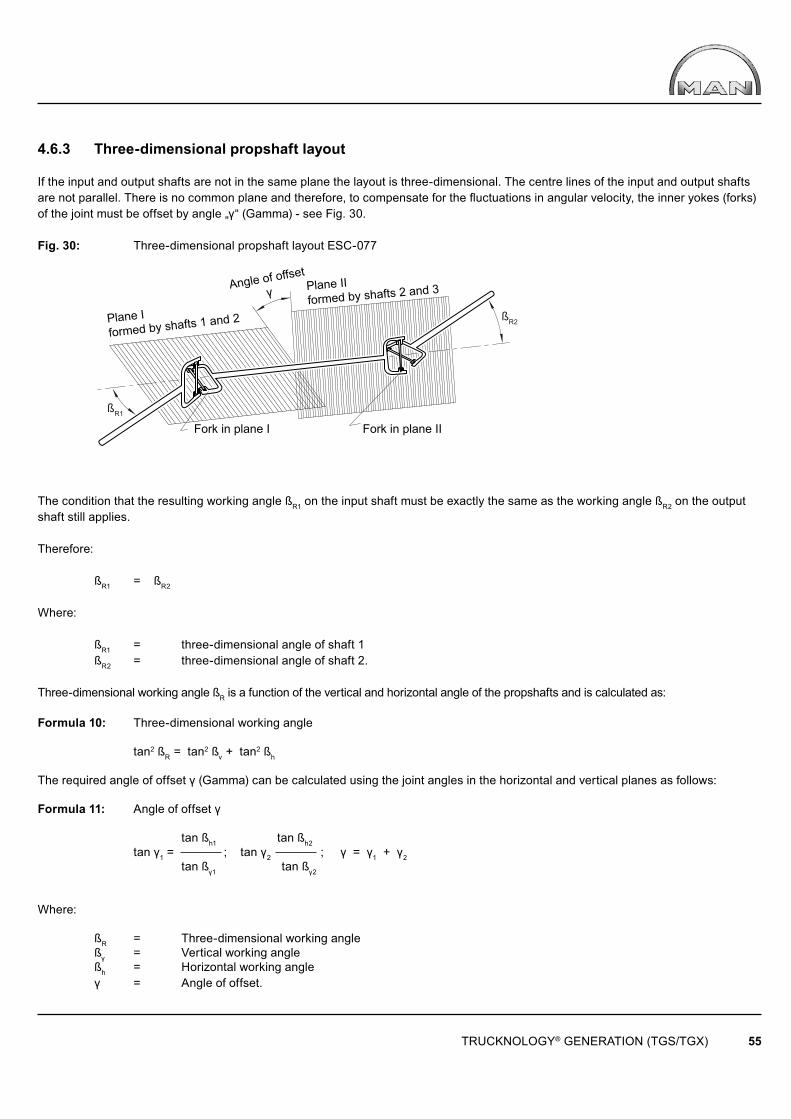
ßR1
ßR2
TRUCKNOLOGY® GENERATION (TGS/TGX) 55
Angle of offset
γ
Plane Iformed by shafts 1 and 2
Plane IIformed by shafts 2 and 3
Fork in plane I Fork in plane II
4.6.3 Three-dimensional propshaft layout
If the input and output shafts are not in the same plane the layout is three-dimensional. The centre lines of the input and output shafts are not parallel. There is no common plane and therefore, to compensate for the fl uctuations in angular velocity, the inner yokes (forks) of the joint must be offset by angle „γ“ (Gamma) - see Fig. 30.
Fig. 30: Three-dimensional propshaft layout ESC-077
The condition that the resulting working angle ßR1 on the input shaft must be exactly the same as the working angle ßR2 on the output shaft still applies.
Therefore:
ßR1 = ßR2
Where:
ßR1 = three-dimensional angle of shaft 1 ßR2 = three-dimensional angle of shaft 2.
Three-dimensional working angle ßR is a function of the vertical and horizontal angle of the propshafts and is calculated as:
Formula 10: Three-dimensional working angle tan2 ßR = tan2 ßv + tan2 ßh
The required angle of offset γ (Gamma) can be calculated using the joint angles in the horizontal and vertical planes as follows:
Formula 11: Angle of offset γ tan ßh1 tan ßh2 tan γ1 = ; tan γ2 ; γ = γ1 + γ2 tan ßγ1 tan ßγ2
Where:
ßR = Three-dimensional working angle ßγ = Vertical working angle ßh = Horizontal working angle γ = Angle of offset.
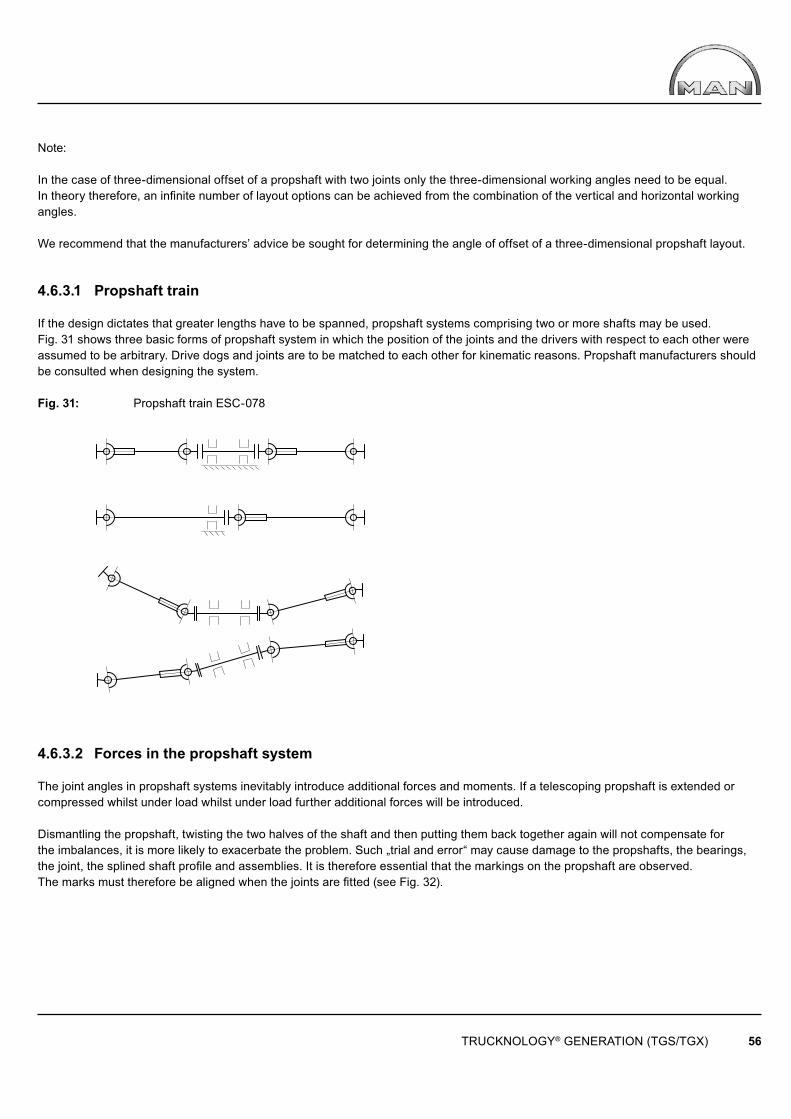
TRUCKNOLOGY® GENERATION (TGS/TGX) 56
Note:
In the case of three-dimensional offset of a propshaft with two joints only the three-dimensional working angles need to be equal. In theory therefore, an infi nite number of layout options can be achieved from the combination of the vertical and horizontal working angles.
We recommend that the manufacturers’ advice be sought for determining the angle of offset of a three-dimensional propshaft layout.
4.6.3.1 Propshaft train
If the design dictates that greater lengths have to be spanned, propshaft systems comprising two or more shafts may be used. Fig. 31 shows three basic forms of propshaft system in which the position of the joints and the drivers with respect to each other were assumed to be arbitrary. Drive dogs and joints are to be matched to each other for kinematic reasons. Propshaft manufacturers should be consulted when designing the system.
Fig. 31: Propshaft train ESC-078
4.6.3.2 Forces in the propshaft system
The joint angles in propshaft systems inevitably introduce additional forces and moments. If a telescoping propshaft is extended or compressed whilst under load whilst under load further additional forces will be introduced.
Dismantling the propshaft, twisting the two halves of the shaft and then putting them back together again will not compensate for the imbalances, it is more likely to exacerbate the problem. Such „trial and error“ may cause damage to the propshafts, the bearings, the joint, the splined shaft profi le and assemblies. It is therefore essential that the markings on the propshaft are observed. The marks must therefore be aligned when the joints are fi tted (see Fig. 32).

ß2
ß1
TRUCKNOLOGY® GENERATION (TGS/TGX) 57
Fig. 32: Marking on propshaft ESC-079
Do not remove existing balancing plates and do not confuse propshaft parts otherwise imbalances will occur again. If one of the balancing plates is lost or propshaft parts are replaced, the propshaft should be re-balanced.Despite careful design of a propshaft system, vibrations may occur that may cause damage if the cause is not eliminated.Suitable measures must be used to cure the problem such as installing dampers, the use of constant velocity joints or changing the entire propshaft system and the mass ratios.
4.6.4 Modifying the propshaft layout in the driveline of MAN chassis
Body manufacturers normally modify the propshaft system when:
• Modifying the wheelbase as a retrofi t operation• Installing pumps on the driveshaft fl ange of the power take-off.
In such cases the following must be observed:
• The working angle of each cardan shaft in the driveline must be 7° maximum in each plane when loaded.• If propshafts are to be extended the entire propshaft system must be re-designed by a propshaft manufacturer.• Modifi cations to the propshaft, such as extensions, may only be carried out by authorised workshops• Every propshaft must be balanced before installation.• Allowing the propshaft to hang on one side when fi tting or removing it may lead to the shaft becoming damaged.• A clearance of at least 30mm must be maintained.
When assessing the minimum clearance, the raising of the vehicle and associated movement of the axle due to the extension of the springs and resulting change in position of the propshaft must be taken into consideration.
4.7 Modifying the wheel formula
Modifying the wheel formula means: • The installation of extra axles• The removal of axles• Changing the type of suspension (e.g. from leaf suspension to air suspension)• Making non-steered axles steerable
Modifi cations to the wheel formula are prohibited. Such conversions are only to be carried out by MAN Truck & Bus and its suppliers.
4.7.1 Safety-related components
Modifi cations and changes to the following components:
• Axle guide members (e.g. on control arms) • The steering system (e.g. on the steering arm) • Suspension (e.g. stabilisers)• The braking system
together with their mountings and fastenings are not permitted.Suspension components or spring leaves may not be removed or modifi ed. Leaf springs may be replaced only as a complete part and only in pairs (left and right-hand side).
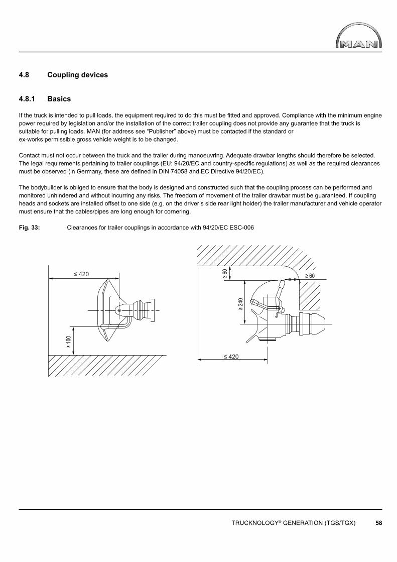
≥ 60
≥ 100
≥ 60
≥ 240
≤ 420
≤ 420
TRUCKNOLOGY® GENERATION (TGS/TGX) 58
4.8 Coupling devices
4.8.1 Basics
If the truck is intended to pull loads, the equipment required to do this must be fi tted and approved. Compliance with the minimum engine power required by legislation and/or the installation of the correct trailer coupling does not provide any guarantee that the truck is suitable for pulling loads. MAN (for address see “Publisher” above) must be contacted if the standard or ex-works permissible gross vehicle weight is to be changed.
Contact must not occur between the truck and the trailer during manoeuvring. Adequate drawbar lengths should therefore be selected.The legal requirements pertaining to trailer couplings (EU: 94/20/EC and country-specifi c regulations) as well as the required clearances must be observed (in Germany, these are defi ned in DIN 74058 and EC Directive 94/20/EC).
The bodybuilder is obliged to ensure that the body is designed and constructed such that the coupling process can be performed and monitored unhindered and without incurring any risks. The freedom of movement of the trailer drawbar must be guaranteed. If coupling heads and sockets are installed offset to one side (e.g. on the driver’s side rear light holder) the trailer manufacturer and vehicle operator must ensure that the cables/pipes are long enough for cornering.
Fig. 33: Clearances for trailer couplings in accordance with 94/20/EC ESC-006

140m
in.
A A
250max.
300max.
R20max.
R40max.
100max.
45°max.
30°m
ax.
30°max.
65°min.
300max.
55m
in.
32m
in.
350m
in.
420m
ax.
45°m
in. 75
min
.75
min
.
100max.
15°max.
30°max.
65min.
TRUCKNOLOGY® GENERATION (TGS/TGX) 59
Fig. 34: Clearances for trailer couplings in accordance with DIN 74058 ESC-152
Only original MAN end cross members and their associated reinforcement plates may be used when fi tting trailer couplings. End cross members have a hole pattern that matches that of the associated trailer coupling. This hole pattern may under no circumstances be modifi ed to suit a different trailer coupling. The guidelines provided in the coupling manufacturers’ installation instructions must be observed (e.g. tightening torques and their checking).Lowering the trailer coupling without also lowering the end cross member is not permitted! Some examples of how the coupling may be lowered are shown in Figs. 35 and 36.These examples are purposely represented only schematically – they do not form a design instruction. Design responsibility rests with the respective bodybuilder/ converter.
Fig. 35: Lowered trailer coupling ESC-515

TRUCKNOLOGY® GENERATION (TGS/TGX) 60
Fig. 36: Trailer coupling fi tted below the frame ESC-542
4.8.2 Trailer coupling, D value
See the booklet ‘Coupling devices TG’ for detailed derivation of the D value and – for rigid drawbar trailers – Dc and V values. Example calculations can be found in the ‘Calculations’ Chapter 9.
4.9 Tractor units and converting the vehicle type - truck / tractor
4.9.1 Articulated vehicles
The weight and size of semitrailers and semitrailer tractors must be checked to see if they are suitable for forming an articulated vehicle.
The following must therefore be checked:
• Slew radii• Fifth-wheel height• Fifth-wheel load• Freedom of movement of all parts• Legal requirements.
In order to achieve maximum fi fth-wheel load the following actions are required before the vehicle goes into operation:
• Weigh the vehicle• Calculate the axle loads• Determine the optimum fi fth-wheel lead• Check the front slew radius• Check the rear slew radius• Check the front angle of inclination• Check the rear angle of inclination• Check the overall length of the articulated vehicle• Install the fi fth-wheel coupling accordingly.
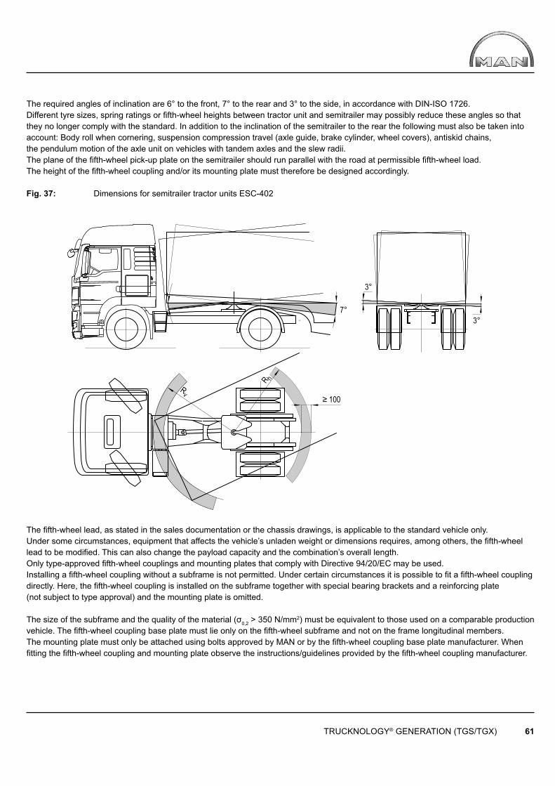
TRUCKNOLOGY® GENERATION (TGS/TGX) 61
The required angles of inclination are 6° to the front, 7° to the rear and 3° to the side, in accordance with DIN-ISO 1726.Different tyre sizes, spring ratings or fi fth-wheel heights between tractor unit and semitrailer may possibly reduce these angles so that they no longer comply with the standard. In addition to the inclination of the semitrailer to the rear the following must also be taken into account: Body roll when cornering, suspension compression travel (axle guide, brake cylinder, wheel covers), antiskid chains, the pendulum motion of the axle unit on vehicles with tandem axles and the slew radii.The plane of the fi fth-wheel pick-up plate on the semitrailer should run parallel with the road at permissible fi fth-wheel load.The height of the fi fth-wheel coupling and/or its mounting plate must therefore be designed accordingly.
Fig. 37: Dimensions for semitrailer tractor units ESC-402
The fi fth-wheel lead, as stated in the sales documentation or the chassis drawings, is applicable to the standard vehicle only.Under some circumstances, equipment that affects the vehicle’s unladen weight or dimensions requires, among others, the fi fth-wheel lead to be modifi ed. This can also change the payload capacity and the combination’s overall length.Only type-approved fi fth-wheel couplings and mounting plates that comply with Directive 94/20/EC may be used.Installing a fi fth-wheel coupling without a subframe is not permitted. Under certain circumstances it is possible to fi t a fi fth-wheel coupling directly. Here, the fi fth-wheel coupling is installed on the subframe together with special bearing brackets and a reinforcing plate (not subject to type approval) and the mounting plate is omitted.
The size of the subframe and the quality of the material (σ0,2 > 350 N/mm2) must be equivalent to those used on a comparable production vehicle. The fi fth-wheel coupling base plate must lie only on the fi fth-wheel subframe and not on the frame longitudinal members. The mounting plate must only be attached using bolts approved by MAN or by the fi fth-wheel coupling base plate manufacturer. When fi tting the fi fth-wheel coupling and mounting plate observe the instructions/guidelines provided by the fi fth-wheel coupling manufacturer.
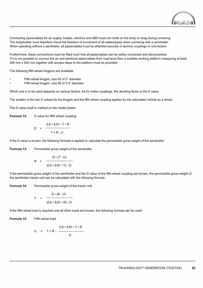
TRUCKNOLOGY® GENERATION (TGS/TGX) 62
Connecting pipes/cables for air supply, brakes, electrics and ABS must not chafe on the body or snag during cornering. The bodybuilder must therefore check the freedom of movement of all cables/pipes when cornering with a semitrailer.When operating without a semitrailer, all pipes/cables must be attached securely in dummy couplings or connectors.
Furthermore, these connections must be fi tted such that all pipes/cables can be safely connected and disconnected. If it is not possible to connect the air and electrical pipes/cables from road level then a suitable working platform measuring at least 400 mm x 500 mm together with access steps to the platform must be provided.
The following fi fth-wheel kingpins are available:
• Fifth-wheel kingpin, size 50 of 2“ diameter• Fifth-wheel kingpin, size 90 of 3.5“ diameter
Which one is to be used depends on various factors. As for trailer couplings, the deciding factor is the D value.
The smaller of the two D values for the kingpin and the fi fth-wheel coupling applies for the articulated vehicle as a whole.
The D value itself is marked on the model plates:
Formula 12: D value for fi fth-wheel coupling
0,6 • 9,81 • T • R D = T + R - U
If the D value is known, the following formula is applied to calculate the permissible gross weight of the semitrailer:
Formula 13: Permissible gross weight of the semitrailer
D • (T - U) R = (0,6 • 9,81 • T) - D
If the permissible gross weight of the semitrailer and the D value of the fi fth-wheel coupling are known, the permissible gross weight of the semitrailer tractor unit can be calculated with the following formula:
Formula 14: Permissible gross weight of the tractor unit
D • (R - U) T = (0,6 • 9,81 • R) - D
If the fi fth-wheel load is required and all other loads are known, the following formula can be used:
Formula 15: Fifth-wheel load
0,6 • 9,81 • T • R U = T + R - D
TRUCKNOLOGY® GENERATION (TGS/TGX) 63
Where:
D = D value [ in kN ] R = Permissible gross weight of the semitrailer [ in t ], including the fi fth-wheel load T = Permissible gross weight of the semitrailer tractor [ in t ], including the fi fth-wheel load U = Fifth-wheel load [ in t ]
Examples of calculations can be found in the „Calculations“ Chapter 9.
4.9.2 Converting trucks into tractor units or tractor units into trucks
Conversion of a truck into a tractor unit or of a tractor unit into a truck or using the same vehicle alternatively as a tractor unit or truck requires approval from MAN. MAN can provide further information (for address see “Publisher” above).When converting a tractor unit to a truck or vice-versa, it is necessary to modify the vehicle’s EBS (brake) parameterisation. Depending upon the vehicle undergoing conversion (leaf suspension), this may also involve installing different rear springs.
Due to the rear axle guide member, possible equipment with fi fth wheel ESP and fifth wheel level adjustment, two-axle tractor units with wheel formulae 4x2 and 4x4H can only be used as semitrailer tractors. Operation as a combined articulated vehicle/truck is not permitted.
Models as of 03-2010: 05X, 06S, 06X, 08S, 10S. 10X, 13S, 13X, 22S, 22X, 78 X. Therefore, in the case of new-build vehicles to be used as both tractor units and trucks, always select a truck chassis as a basis. Exceptions, even in connection with further vehicle conversions require written approval from MAN (for address see “Publisher” above).An exception are car transporters, see Chapter 5.4, Bodies.
4.10 Modifying the cab
4.10.1 General
Modifi cations to the cab’s structure (e.g. incisions/cut-outs, changes to the support structure including the seats and seat mountings, cab extensions) together with modifi cations to the cab mountings and tilting mechanism are prohibited. Such modifi cations are only to be carried out by qualifi ed MAN Truck & Bus AG and its qualifi ed conversion suppliers.
4.10.2 Spoilers, roof extensions, roofwalk
It is possible to retrofi t a roof spoiler or an aerodynamics kit. Original MAN spoilers and aerodynamics kits can be obtained for retrofi tting from our spare parts service. Drawings can be found in MANTED® under ‘Cabs’. Only the proper mounting points on the cab roof should be used when retrofi tting components to the cab roof.
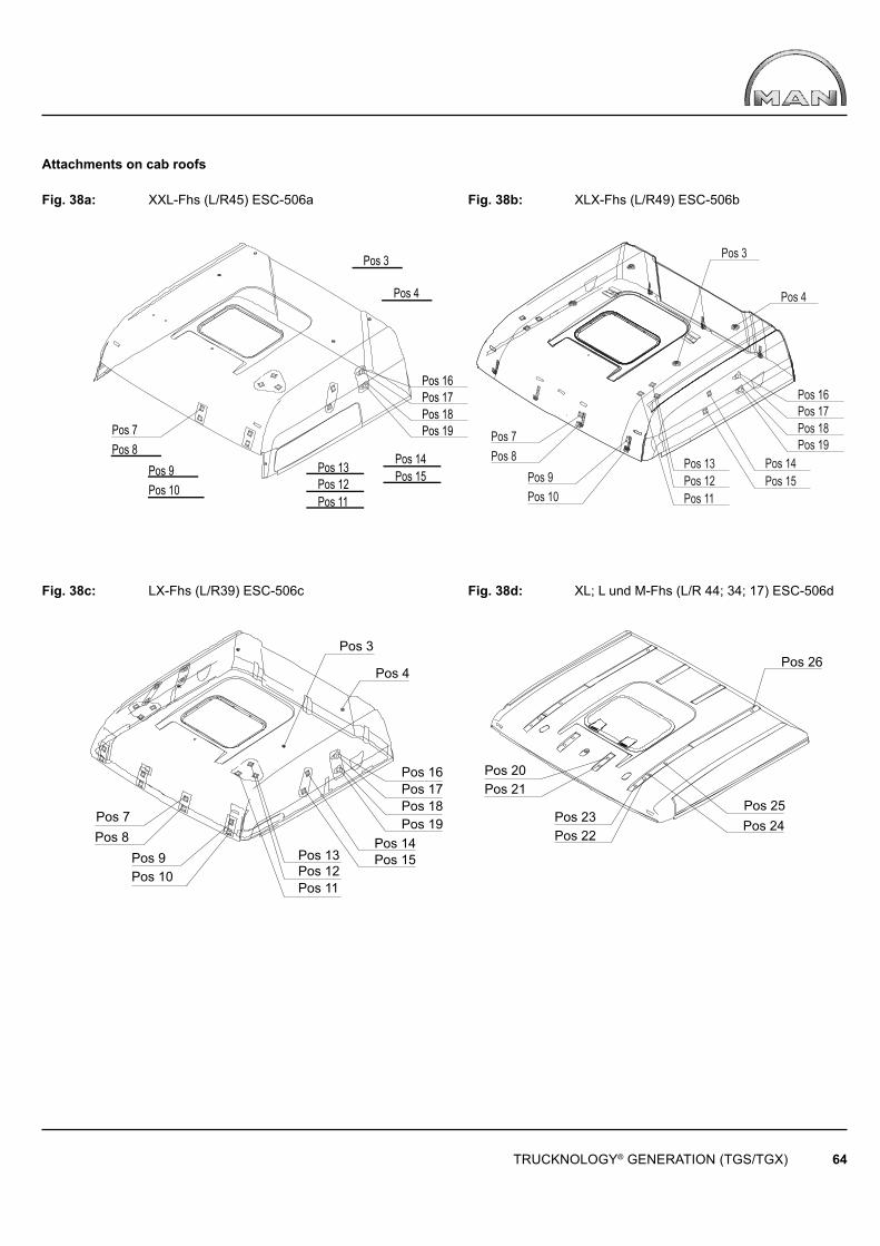
Pos 11
Pos 13Pos 12 Pos 15
Pos 14
Pos 3
Pos 4
Pos 16Pos 17Pos 18Pos 19Pos 7
Pos 8Pos 9Pos 10
Pos 7Pos 8
Pos 9Pos 10 Pos 11
Pos 12Pos 13 Pos 14
Pos 15
Pos 16Pos 17Pos 18Pos 19
Pos 4
Pos 3
Pos 3
Pos 7Pos 8
Pos 9Pos 10
Pos 13
Pos 16
Pos 14Pos 15
Pos 17Pos 18Pos 19
Pos 12Pos 11
Pos 4Pos 26
Pos 25Pos 24Pos 23
Pos 22
Pos 20Pos 21
TRUCKNOLOGY® GENERATION (TGS/TGX) 64
Attachments on cab roofs
Fig. 38a: XXL-Fhs (L/R45) ESC-506a Fig. 38b: XLX-Fhs (L/R49) ESC-506b
Fig. 38c: LX-Fhs (L/R39) ESC-506c Fig. 38d: XL; L und M-Fhs (L/R 44; 34; 17) ESC-506d
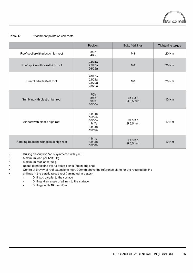
TRUCKNOLOGY® GENERATION (TGS/TGX) 65
Table 17: Attachment points on cab roofs
Position Bolts / drillings Tightening torque
Roof spoilerwith plastic high roof 3/3a4/4a M8 20 Nm
Roof spoilerwith steel high roof24/24a25/25a26/26a
M8 20 Nm
Sun blindwith steel roof
20/20a21/21a22/22a23/23a
M8 20 Nm
Sun blindwith plastic high roof
7/7a8/8a9/9a
10/10a
St 6,3 /Ø 5,5 mm 10 Nm
Air hornwith plastic high roof
14/14a15/15a16/16a17/17a18/18a19/19a
St 6,3 /Ø 5,5 mm 10 Nm
Rotating beacons with plastic high roof11/11a12/12a13/13a
St 6,3 /Ø 5,5 mm 10 Nm
• Drilling description “a” is symmetric with y = 0• Maximum load per bolt: 5kg• Maximum roof load: 30kg• Bolted connections over 3 offset points (not in one line)• Centre of gravity of roof extensions max. 200mm above the reference plane for the required bolting• drillings in the plastic raised roof (laminated-in plates): - Drill axis parallel to the surface - Drilling at an angle of ±2 mm to the surface - Drilling depth 10 mm +2 mm
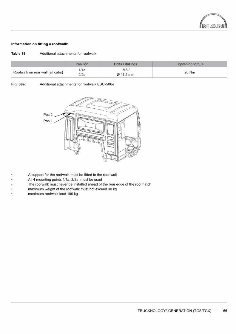
Pos 2
Pos 1
TRUCKNOLOGY® GENERATION (TGS/TGX) 66
Information on fitting a roofwalk:
Table 18: Additional attachments for roofwalk
Position Bolts / drillings Tightening torque
Roofwalk on rear wall (all cabs)1/1a2/2a
M8 / Ø 11,2 mm
20 Nm
Fig. 38e: Additional attachments for roofwalk ESC-506e
• A support for the roofwalk must be fitted to the rear wall• All 4 mounting points 1/1a, 2/2a must be used• The roofwalk must never be installed ahead of the rear edge of the roof hatch• maximum weight of the roofwalk must not exceed 30 kg• maximum roofwalk load 100 kg.

y
825
825 ± 10%
820
± 10
%
560
y
TRUCKNOLOGY® GENERATION (TGS/TGX) 67
Centre of gravity of top sleeper
Resulting centre of gravity
Dimension γ will be determined by the body builder
Cab fl oor
Cab centre of gravity
approx. 660 kg
4.10.3 Roof sleeper cabs
It is possible to install roof sleeper cabs (top-sleepers) and raised roofs provided that the following conditions are met:
• Approval must be obtained from MAN. This is the responsibility of the roof cab manufacturer and not the workshop carrying out the work; see Section 4.5 “Retrofi tting additional equipment add-on components or accessories” in this Guide to Fitting Bodies. • The manufacturer of the roof cab is responsible for compliance with regulations (in particular safety regulations, e.g. trade association guidelines), regulations and laws (e.g. GGVS/ADR).• A suitable method of preventing the cab from closing by itself when it is tilted must be installed (e.g. by fi tting a securing device)• If the tilting process differs from that for the standard MAN cab, a simple but comprehensive operating manual must be drawn up.• The resulting centre of gravity of the extended cab must be in line with the specifi cations, and evidence of this compliance must be provided (see Fig. 39).• Roof sleeper cabs may only be installed on vehicles fi tted with an air suspended cab. • The maximum weights listed in table 19 are to be observed.
The antennas fi tted on original MAN cab roofs must be properly moved. This is intended to ensure good quality reception and transmission of electromagnetic radiation in accordance with the EMC Directive. Extension of the antenna cable (by splicing extra cable lengths in) is not permitted.
Fig. 39: Cab centre of gravity with roof sleeper cab ESC-410
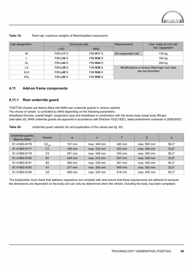
TRUCKNOLOGY® GENERATION (TGS/TGX) 68
Table 19: Roof cab, maximum weights of fi tted/installed components
Cab designation Technical code Requirements max. mass of roof cab incl. equipment LHD RHD
M F99 L17 S F99 R17 S Air-suspended cab 130 kgL F99 L34 S F99 R34 S 180 kg
XL F99 L44 S F99 R44 S 200 kgLX F99 L39 S F99 R39 S Modifi cations to factory fi tted high roof cabs
are not permittedXLX F99 L49 S F99 R49 SXXL F99 L45 S F99 R45 S
4.11 Add-on frame components
4.11.1 Rear underride guard
TGS/TGX-chassis are factory-fitted with MAN rear underride guards in various variants. The choice of variant is controlled by MAN depending on the following parameters:wheelbase formula, overall height, suspension type and wheelbase in combination with the works body (swap body fittings) (see table 20). MAN underride guards are approved in accordance with Directive 70/221/EEC, latest amendment contained in 2006/20/EC.
Table 20: Underride guard variants (for and explanation of the values see fi g. 40)
Underride guards fi tted by MAN
Version w x Y Z α
81.41660-8176 C2WB 191 mm max. 348 mm 340 mm max. 550 mm 56,3°81.41660-8177 C1 199 mm max. 332 mm 432 mm max. 550 mm 33,8°81.41660-8178 C2 291 mm max. 348 mm 340 mm max. 550 mm 56,3°81.41660-8180 B1 249 mm max. 318 mm 507 mm max. 550 mm 33,8°81.41660-8181 B2 366 mm max. 339 mm 391 mm max. 550 mm 56,3°81.41660-8183 A1 277 mm max. 305 mm 549 mm max. 550 mm 33,8°81.41660-8184 A2 408 mm max. 330 mm 418 mm max. 550 mm 56,3°
The bodybuilder must check that statutory regulations are complied with and ensure that these requirements are adhered to because the dimensions are dependent on the body and can only be determined when the vehicle, including the body, has been completed.
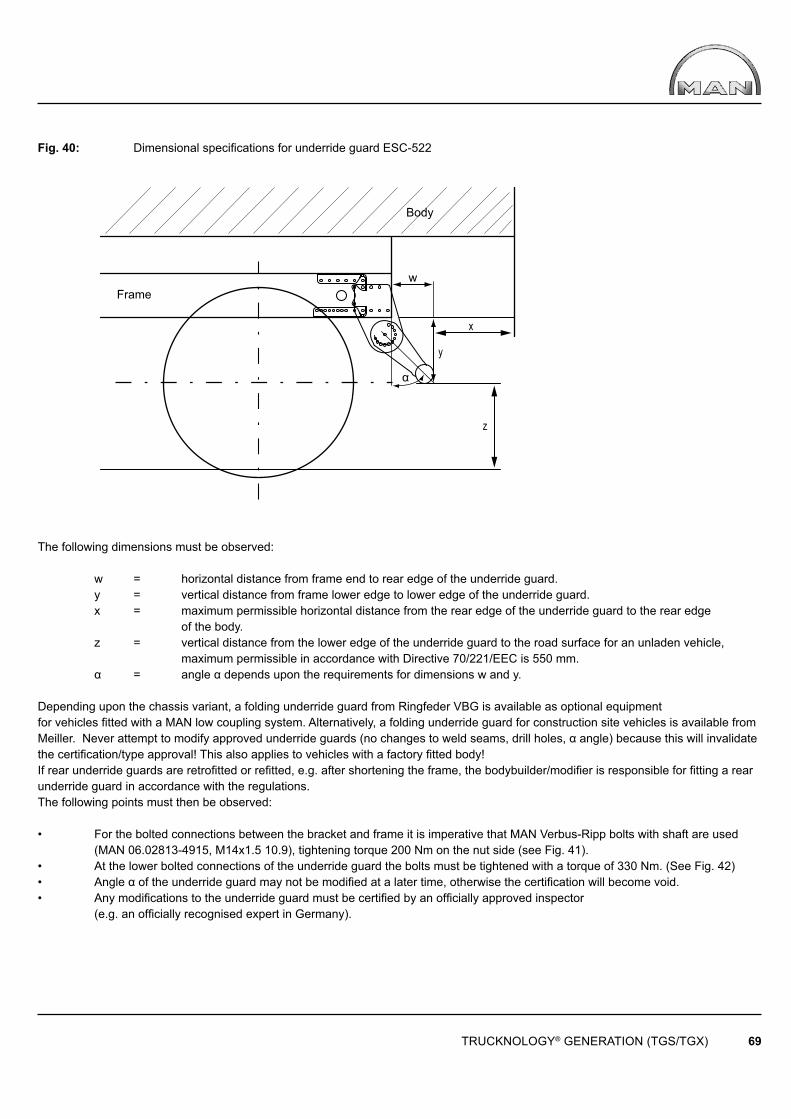
x
y
z
α
w
TRUCKNOLOGY® GENERATION (TGS/TGX) 69
Body
Frame
Fig. 40: Dimensional specifi cations for underride guard ESC-522
The following dimensions must be observed:
w = horizontal distance from frame end to rear edge of the underride guard. y = vertical distance from frame lower edge to lower edge of the underride guard. x = maximum permissible horizontal distance from the rear edge of the underride guard to the rear edge of the body. z = vertical distance from the lower edge of the underride guard to the road surface for an unladen vehicle, maximum permissible in accordance with Directive 70/221/EEC is 550 mm. α = angle α depends upon the requirements for dimensions w and y.
Depending upon the chassis variant, a folding underride guard from Ringfeder VBG is available as optional equipmentfor vehicles fitted with a MAN low coupling system. Alternatively, a folding underride guard for construction site vehicles is available from Meiller. Never attempt to modify approved underride guards (no changes to weld seams, drill holes, α angle) because this will invalidate the certification/type approval! This also applies to vehicles with a factory fi tted body!If rear underride guards are retrofi tted or refi tted, e.g. after shortening the frame, the bodybuilder/modifi er is responsible for fitting a rear underride guard in accordance with the regulations. The following points must then be observed:
• For the bolted connections between the bracket and frame it is imperative that MAN Verbus-Ripp bolts with shaft are used (MAN 06.02813-4915, M14x1.5 10.9), tightening torque 200 Nm on the nut side (see Fig. 41).• At the lower bolted connections of the underride guard the bolts must be tightened with a torque of 330 Nm. (See Fig. 42)• Angle α of the underride guard may not be modifi ed at a later time, otherwise the certification will become void. • Any modifi cations to the underride guard must be certifi ed by an offi cially approved inspector (e.g. an offi cially recognised expert in Germany).
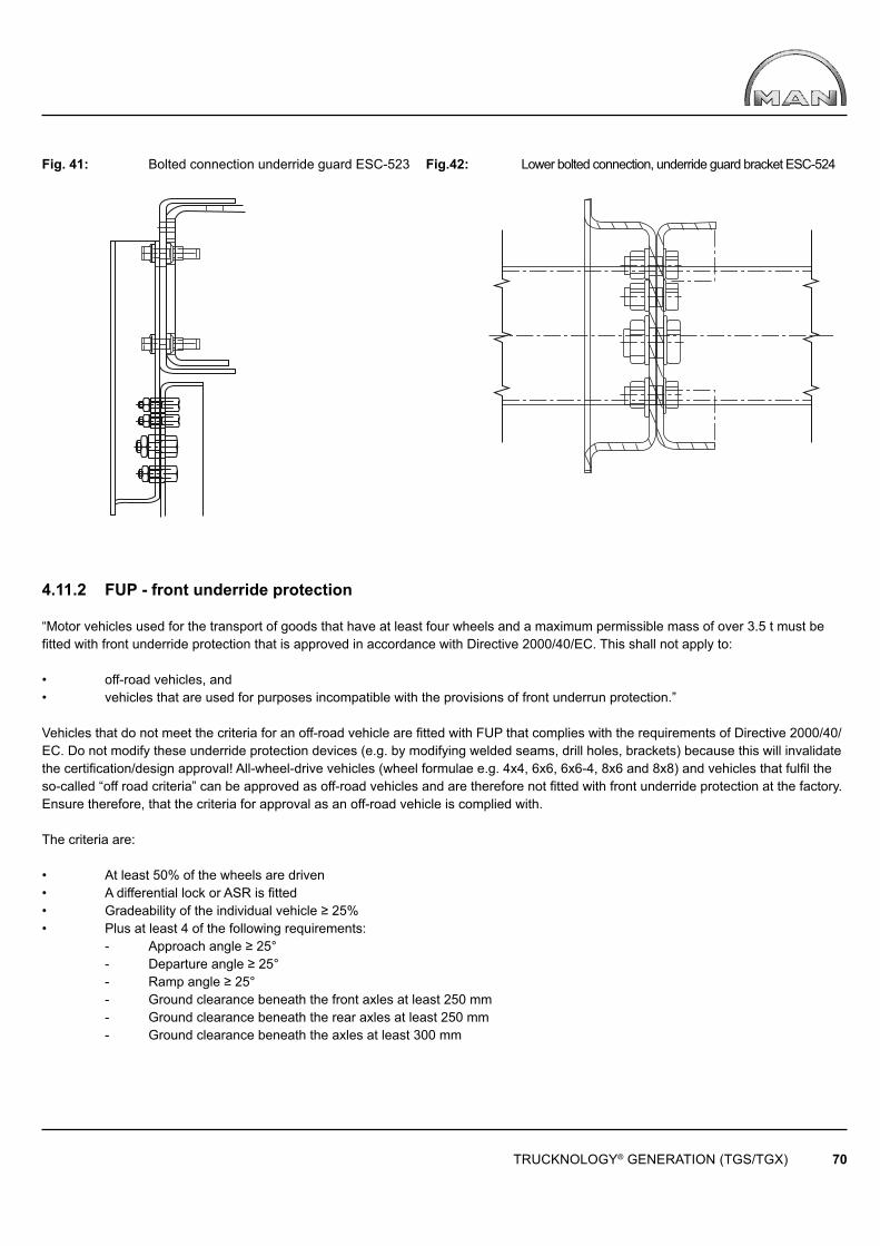
TRUCKNOLOGY® GENERATION (TGS/TGX) 70
Fig. 41: Bolted connection underride guard ESC-523 Fig.42: Lower bolted connection, underride guard bracket ESC-524
4.11.2 FUP - front underride protection
“Motor vehicles used for the transport of goods that have at least four wheels and a maximum permissible mass of over 3.5 t must be fi tted with front underride protection that is approved in accordance with Directive 2000/40/EC. This shall not apply to:
• off-road vehicles, and• vehicles that are used for purposes incompatible with the provisions of front underrun protection.”
Vehicles that do not meet the criteria for an off-road vehicle are fi tted with FUP that complies with the requirements of Directive 2000/40/EC. Do not modify these underride protection devices (e.g. by modifying welded seams, drill holes, brackets) because this will invalidate the certifi cation/design approval! All-wheel-drive vehicles (wheel formulae e.g. 4x4, 6x6, 6x6-4, 8x6 and 8x8) and vehicles that fulfi l the so-called “off road criteria” can be approved as off-road vehicles and are therefore not fi tted with front underride protection at the factory. Ensure therefore, that the criteria for approval as an off-road vehicle is complied with.
The criteria are:
• At least 50% of the wheels are driven• A differential lock or ASR is fi tted• Gradeability of the individual vehicle ≥ 25%• Plus at least 4 of the following requirements: - Approach angle ≥ 25° - Departure angle ≥ 25° - Ramp angle ≥ 25° - Ground clearance beneath the front axles at least 250 mm - Ground clearance beneath the rear axles at least 250 mm - Ground clearance beneath the axles at least 300 mm

a al ≤ 3
00
≤ 3
50 ≤
550
TRUCKNOLOGY® GENERATION (TGS/TGX) 71
Body
If it is not possible to locate bodies and ancillaries (e.g. outriggers, tool boxes) such that the above stated criteria are not violated then the vehicle must be retrofi tted with front underride protection that is available from the MAN spare parts organisation.
Responsibility for this lies with the body builder. MAN is not liable for any costs arising from the retrofi tting of front underride protection to vehicles that were delivered as off-road vehicles.
4.11.3 Sideguards
Side guards (= SSV) protect vulnerable road users from the risk of falling sideways under the vehicle and being run over by the wheels.Trucks, tractor units and their trailers with a permissible gross weight of > 3.5 t must be fi tted with sideguards (= SSV).
Exceptions applicable to the truck sector are as follows:
• Vehicles that are not yet completed (chassis atng delivered)• Tractor units (not semitrailers)• Vehicles built for special purposes that are incompatible with the fi tting of sideguards.
In this connection, special vehicles mainly means vehicles with side tipper. This is only valid for vehicles with side tippers and a body inside length of less then 7,500 mm. Neither vehicles for combined transport nor off-road vehicles are exempt from the mandatory requirement for fi tting SSVs.For MAN chassis it is possible to obtain sideguards ex-works. If the body manufacturer is to retrofit sideguards to the chassis, then profile sections, profile supports and installation parts are available from MAN in a variety of designs. The company installing the sideguards is responsible for compliance with legal regulations (regulated by Directive 89/297/EEC and in Germany by §32c StVZO (Road Traffic Licensing Regulations).It is not permissible to attach brake, air or hydraulic pipes to the sideguards; there may be no sharp edges or burrs; the rounding-off radius for all parts cut to size by the bodybuilder must be at least 2.5 mm; rounded bolts and rivets may project by a maximum of 10 mm. If the vehicle is fitted with different tyres or different springs, the height of the guards must be checked and if necessary, corrected. If there are several components in a row (battery box, tool box …) that serve as a form of SSV, a maximum distance of 25 mm is permissible but the rear component may not project over the front component.
If it is necessary for the body builder to modify the original MAN sideguard profile then the relationship between the span “I” (= L2 in the diagram) and projection “a” (= L3 in the diagram) apply as illustrated in the following diagram in accordance with Fig. 44. If, according to expert opinion, the permitted dimensions are exceeded then the body builder must arrange for strength testing to be carried out. The illustrations are only intended to clarify the dimensions for which the MAN sideguard strength requirements are met.
Fig. 43: TGA sideguards ESC-460
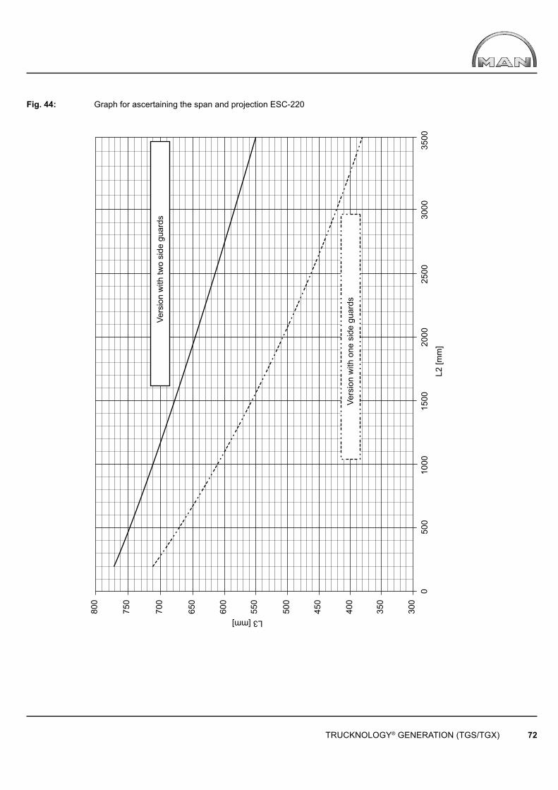
3000
3500
030
0
350
400
450
500
550
600
650
700
750
800
500
1000
1500
2000
2500
L2 [m
m]
L3 [mm]
TRUCKNOLOGY® GENERATION (TGS/TGX) 72
Vers
ion
with
two
side
gua
rds
Vers
ion
with
one
sid
e gu
ards
Fig. 44: Graph for ascertaining the span and projection ESC-220
TRUCKNOLOGY® GENERATION (TGS/TGX) 73
4.12 Modifi cations to engine systems
4.12.1 Modifi cations to the air intake system
In general modifi cations to the air intake system are to be avoided. Various factory options are available for the TGS/TGX and body builders should check to see if these can be used. Information on availability for the corresponding vehicle can be obtained from your closest MAN sales branch.
If it is still not possible to avoid making modifi cations the following requirements must be met:
• The fl ow of intake of air must not be inhibited in any way. • The negative pressure in the intake branch must not be allowed to vary.• When modifying the intake system it must be ensured that all statutory regulations are fulfi lled that are relevant to noise and emissions. • All regulations pertaining to the components in question issued by professional associations or similar bodies must also be fulfi lled (e.g. surface temperature in the vicinity of handles/grips) • In the case of modifi ed intake system - MAN cannot guarantee compliance with these and other regulations. Responsibility for this remains with the company performing the modifi cation. This also applies to regulations pertaining to on board diagnosis systems (OBD). - MAN can provide no information about changes in fuel consumption or noise characteristics; in some circumstances a new noise emission approval will be required. Components that have an effect on the vehicle’s acoustics (e.g. nozzles in the air fi ter) may not be modified. If the noise limits are exceeded the type approval will become invalid!
For vehicles up to and including Euro 5, the following applies in addition to the general requirements:
• Never change the shape or area of pipework cross-sections.• Sharp bends in the pipework should be avoided, mitre cuts are not permitted. • Do not modify air filters.• The service life of the air fi lter may be shortened when modifi cations are made to the air intake.• Only approved air fi lter elements should be used.• The installation position of the humidity sensor in the air filter must not be changed.• The design of mountings and supports and the basic installation position of components must not be changed.• The air intake must be protected against ingesting warmed air (e.g. engine heat from the wheel arches or in the vicinity of the exhaust silencer). A suitable position for the air intake must be chosen such that the intake air is not warmed by more than 5°C (difference between the ambient air temperature and the temperature at the turbocharger inlet). If the intake air temperature is too high there is a risk that exhaust emission limits will be exceeded. If the exhaust emission limits are exceeded the type approval will become invalid!• In order to avoid the ingestion of burning cigarette ends or similar a so-called cigarette mesh must be fitted directly over the air intake in the same fashion as the mesh installed on production vehicles (non-flammable material, mesh size SW6, area of the open cross-section at least that of the intake air scoop on the air filter). There is a risk of vehicle fire if this requirement is not observed! MAN can provide no information on the effectiveness of the measure used, responsibility lies with the company performing the modification.• The air intake must be positioned such that there is a low level of dust and spray ingestion.• Sufficient dewatering using water separation systems and unobstructed dust discharge from the filter housing and the unfiltered side must be ensured otherwise damage may result.• Pipework on the filtered-air side must be selected to ensure that it is absolutely sealed from the unfiltered side. The inside of the air intake pipes must be smooth – no particles or similar may come loose from the sides. It is imperative that the air intake pipe cannot slip out at the sealed joints. Suitable brackets must therefore be fitted.• The vacuum sensor should be positioned in a straight section of the pipe at the shortest possible distance from the turbocharger. It is the responsibility of the company carrying out the modification to ensure the sensor reads correctly.

TRUCKNOLOGY® GENERATION (TGS/TGX) 74
Caution: Risk of engine damage if the sensor under reads!
• All intake trunking must be capable of resisting vacuum pressures of 100mbar and temperatures of at least 80°C (peaks of 100°C). Flexible tubing (e.g. hoses) are not permitted.
For vehicles up to and including Euro 6, the following applies in addition to the general requirements:
• Modifi cations to the air intake system may only be undertaken following written request and approval by MAN (for address see “Publisher” above).• When installing the air compressor suction pipes, cross sections of suffi cient size must be provided. The pipe must have a vacuum stability of at least 250 mbar and a temperature stability range of between -40°C and +120°C.• Modifi cations to the installed position, placement and alignment of sensors in the air intake system are not allowed.• Independent retrofi tting or removing of the safety elements (for diffi cult conditions) leads to non-compliance with the emission limit values. Retrofi tting may only be carried out by MAN workshops. Under certain circumstances the vehicle will require parameterisation.
4.12.2 Modifications to exhaust gas routing for engines
In general modifications to the exhaust systems are to be avoided. Various factory options are available for the TGS/TGXand body builders should check to see if these can be used. The possible variants according to chassis type and engine can be found. Information on availability for the corresponding vehicle can be obtained from your closest MAN sales branch.
If it is still not possible to avoid making modifications the following requirements must be met:
• The flow of outflow of exhaust gases must not be inhibited in any way.• The backpressure in the exhaust must not be allowed to vary.• When modifying the exhaust or intake system it must be ensured that all statutory regulations are fulfilled that are relevant to noise and emissions.• All regulations pertaining to the components in question issued by professional associations or similar bodies must also be fulfilled (e.g. surface temperature in the vicinity of handles/grips)• In the case of modified exhaust systems - MAN cannot guarantee compliance with these and other regulations. Responsibility for this remains with the company performing the modification. This also applies to regulations pertaining to on board diagnosis systems (OBD). - MAN can provide no information about changes in fuel consumption or noise characteristics; in some circumstances a new noise emission approval will be required. Components that have an effect on the vehicle’s acoustics may not be modified. If the noise limits are exceeded the type approval will become invalid! - MAN can make no statements regarding compliance with the prescribed exhaust gas emission limits. It may be necessary to obtain an emission certifi cate. If the emission limits are exceeded the type approval will become invalid!• If modifications are made to the exhaust system and the exhaust gas routing then care must be taken to ensure that the exhaust gas stream is not directed at any part of the vehicle and that the direction of the exhaust outlet points away from the vehicle. (observe the relevant national regulations, in Germany this is the StVZO.
For vehicles up to and including Euro 4, the following applies in addition to the general requirements:
• When moving the exhaust silencer it should be ensured that the original MAN bracket is re-used and the basic installation position of components will be unchanged.• The position of the temperature and NOx sensors (where OBD is fitted) on the exhaust silencer must not be changed.• Modifi cations to the original MAN cable harness to the NOX sensor are not permissible.• If other cable harnesses are required, order original MAN cable harnesses from MAN spare-parts service.• CAN cables may not be untwisted as a result of EMC requirements.• Conversion work or modifications to the exhaust gas routing from the exhaust manifold to the metal pipe (see Fig. 45) are not permitted.• No blowing-out of products (e.g. bitumen) using exhaust gas pressure – danger of damage to the exhaust system and engine.• Do not modify the cross-section (shape or area) of pipes. The original type of material must be used for pipes.• Do not modify silencers (including the silencer housing) in such a way that would invalidate the type approval.

TRUCKNOLOGY® GENERATION (TGS/TGX) 75
Metal pipe
Support bracket
Temperature sensor
(On reverse)NOx sensor (only on vehicles fi tted with OBD with NOx analyser, mandatory from 10/2007)
• When bending components, the bending radius must be at least double the diameter of the pipe. The formation of wrinkles is not permissible.• Only continuous bends are permitted, i.e. no mitre cuts.• The function of the OBD relevant components may not be impaired. Should OBD relevant components be manipulated the type approval will become invalid!• The connection of the pressure sensor tube on the silencer must always face the top, the following steel pipe must be• installed so that it rises continuously to connect with the sensor and it must have a minimum length of 300 mm and a maximum length of 400 mm (including the flexible section). The measurement line must be fabricated of M01-942-X6CrNiTi1810-K3-8x1• D4-T3. The general installation position of the pressure sensor must be retained (connection at bottom).• Heat-sensitive components (e.g. pipes, spare wheels) must be fitted at least > 200 mm away from the exhaust; if heatshields are fitted, this clearance may be reduced to ≥ 100 mm.
For Euro 5 vehicles the following applies in addition to the lower emission standard requirements:
• When moving the exhaust silencer it must be ensured that its original MAN support bracket is re-used.
Fig. 45: View of the exhaust silencer support bracket ESC-425
• Extension of the exhaust routing by 1,000 mm is permissible from the metal pipe to the exhaust silencer without fitting high temperature insulation.• Extension of the exhaust routing by > 1,000 mm to max. 2,000 mm is permissible from the metal pipe to the exhaust silencer if suitable high temperature insulation is fitted.
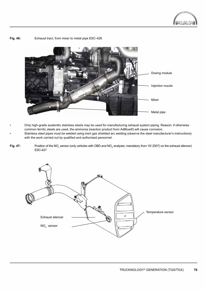
TRUCKNOLOGY® GENERATION (TGS/TGX) 76
Mixer
Metal pipe
Injection nozzle
Dosing module
Exhaust silencer
NOX sensor
Temperature sensor
Fig. 46: Exhaust tract, from mixer to metal pipe ESC-426
• Only high-grade austenitic stainless steels may be used for manufacturing exhaust system piping. Reason: if otherwise common ferritic steels are used, the ammonia (reaction product from AdBlue®) will cause corrosion.• Stainless steel pipes must be welded using inert gas shielded arc welding (observe the steel manufacturer’s instructions) with the work carried out by qualified and authorised personnel.
Fig. 47: Position of the NOx sensor (only vehicles with OBD and NOX analyser, mandatory from 10/ 2007) on the exhaust silencer) ESC-427
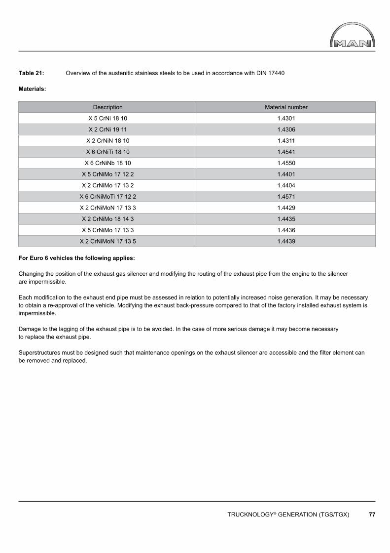
TRUCKNOLOGY® GENERATION (TGS/TGX) 77
Table 21: Overview of the austenitic stainless steels to be used in accordance with DIN 17440
Materials:
Description Material number
X 5 CrNi 18 10 1.4301
X 2 CrNi 19 11 1.4306
X 2 CrNiN 18 10 1.4311
X 6 CrNiTi 18 10 1.4541
X 6 CrNiNb 18 10 1.4550
X 5 CrNiMo 17 12 2 1.4401
X 2 CrNiMo 17 13 2 1.4404
X 6 CrNiMoTi 17 12 2 1.4571
X 2 CrNiMoN 17 13 3 1.4429
X 2 CrNiMo 18 14 3 1.4435
X 5 CrNiMo 17 13 3 1.4436
X 2 CrNiMoN 17 13 5 1.4439
For Euro 6 vehicles the following applies:
Changing the position of the exhaust gas silencer and modifying the routing of the exhaust pipe from the engine to the silencer are impermissible.
Each modifi cation to the exhaust end pipe must be assessed in relation to potentially increased noise generation. It may be necessary to obtain a re-approval of the vehicle. Modifying the exhaust back-pressure compared to that of the factory installed exhaust system is impermissible.
Damage to the lagging of the exhaust pipe is to be avoided. In the case of more serious damage it may become necessary to replace the exhaust pipe.
Superstructures must be designed such that maintenance openings on the exhaust silencer are accessible and the fi lter element can be removed and replaced.

TRUCKNOLOGY® GENERATION (TGS/TGX) 78
AdBlue®
feed pipeAdBlue®
pressure lineDosing line
AdBlue®
return pipeCompressed air line
Air supply
AdBlue® tank Pump module Dosing modul Injection nozzle
4.12.3 Modifi cations to the AdBlue® system
Before commencing with any modification work it should be checked to see if any of the existing MAN variations of the AdBlue® system can be used. All vehicle modifications must be carried out by qualified personnel.
AdBlue® (DIN 70070) is the trade name for an aqueous, synthetically manufactured 32.5% urea solution that is used for exhaust gas after treatment in an SCR (selective catalytic reduction) catalytic converter.
Fig. 48: Schematic overview of the AdBlue® system in Euro 5 vehicles ESC-419
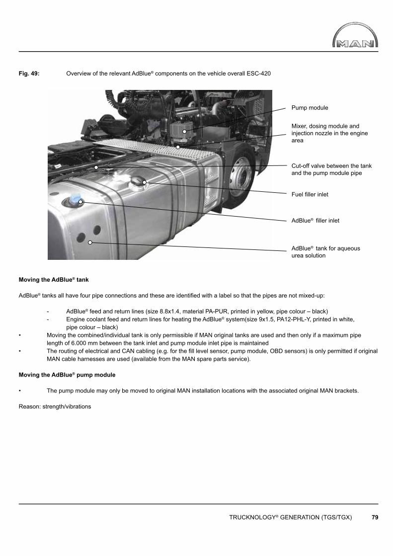
TRUCKNOLOGY® GENERATION (TGS/TGX) 79
Pump module
Mixer, dosing module and injection nozzle in the engine area
Fuel fi ller inlet
AdBlue® filler inlet
AdBlue® tank for aqueous urea solution
Cut-off valve between the tank and the pump module pipe
Fig. 49: Overview of the relevant AdBlue® components on the vehicle overall ESC-420
Moving the AdBlue® tank
AdBlue® tanks all have four pipe connections and these are identifi ed with a label so that the pipes are not mixed-up:
- AdBlue® feed and return lines (size 8.8x1.4, material PA-PUR, printed in yellow, pipe colour – black) - Engine coolant feed and return lines for heating the AdBlue® system(size 9x1.5, PA12-PHL-Y, printed in white, pipe colour – black) • Moving the combined/individual tank is only permissible if MAN original tanks are used and then only if a maximum pipe length of 6.000 mm between the tank inlet and pump module inlet pipe is maintained• The routing of electrical and CAN cabling (e.g. for the fi ll level sensor, pump module, OBD sensors) is only permitted if original MAN cable harnesses are used (available from the MAN spare parts service).
Moving the AdBlue® pump module
• The pump module may only be moved to original MAN installation locations with the associated original MAN brackets. Reason: strength/vibrations
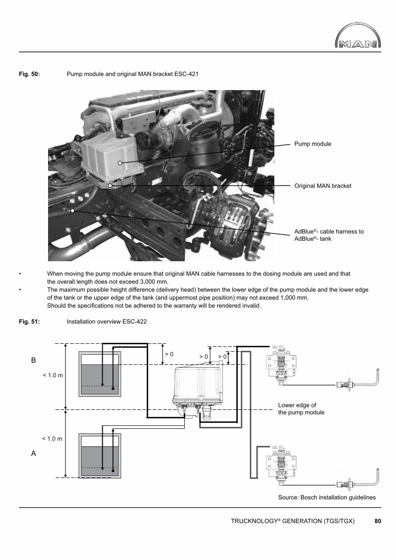
< 1.0 m
< 1.0 m
> 0 > 0 > 0
TRUCKNOLOGY® GENERATION (TGS/TGX) 80
Pump module
Original MAN bracket
AdBlue®- cable harness to AdBlue®- tank
Lower edge of the pump module
Source: Bosch installation guidelines
B
A
Fig. 50: Pump module and original MAN bracket ESC-421
• When moving the pump module ensure that original MAN cable harnesses to the dosing module are used and that the overall length does not exceed 3,000 mm.• The maximum possible height difference (delivery head) between the lower edge of the pump module and the lower edge of the tank or the upper edge of the tank (and uppermost pipe position) may not exceed 1,000 mm. Should the specifications not be adhered to the warranty will be rendered invalid.
Fig. 51: Installation overview ESC-422

TRUCKNOLOGY® GENERATION (TGS/TGX) 81
The chassis drawing depicts a production standard basic vehicle without special equipment fi tted. For special equipment such as different fuel tanks, additional tanks for air suspension in order to accommodate frame adjustments/swap body mountings or silencer variants with raised endpipes a position that deviates from standard may be necessary according to the particular application.
Tables 22 and 23 defi ne the respective dosing module position for solo trucks and tractor units dependant upon the wheel formula, cab and optional equipment.The dosing module position associated with the respective variant is depicted in Figs. 52–62.
Table 22: Possible positions for the AdBlue® system dosing module for solo trucks:
Wheel formula Cab Fuel tank Exhaust Variant Additional information4x2, 4x4H,
6x2/2, 6x2/4, 6x2-2, 6x2-4,
6x4H-2, 6x4H-4, 6x4, 6x6H
L - XXL AdBlue single tankLeft-hand side mounted
exhaust, production standard
1
Caution! Also applies to the M cab, if fi tted with additional
tanks for air suspension in order to accommodate frame adjustments/swap body
mountings4x2, 4x4H,
6x2/2, 6x2/4, 6x2-2, 6x2-4,
6x4H-2, 6x4H-4, 6x4, 6x6H
6X4H/2, 6X4H/4
M - XXLAdBlue/Diesel
combi tank
Left-hand side mounted exhaust, production
standard2
Caution! Change to variant 1 if fi tted with additional tanks for air
suspension in order to accommodate frame
adjustments/swap body mountings. 6x4, 6x6H, 6x4H-4
(71S) from June 2010
6x4, 6x6H, 6X4H-4
M
AdBlue/Diesel combi tank
Left-hand side mounted exhaust, production
standard
36x4, 6x6H, 6x4H-4 (71S)
Up to May 2010
4x2, 4x4H, 6x2/2, 6x2/4, 6x2-2, 6x2-4,
6x4H-2, 6x4H-4, 6x4, 6x6H
AdBlue/Diesel combi tank
Exhaust with raised endpipe
8x4-4 All variants All variants4x2, 4x4H, 6x4,
6x6H, 6x2-2,6x2-4, 6x4H-2,
6x4H-4, 6x2/2, 6x2/44x4, 6x4-4, 6x6
AdBlue single tank All variants
8x2-4, 8x2-6, 8x4, 8x4H-6,
8x6, 8x6H, 8x8M AdBlue single tank All variants 4
Only possible with AdBlue single tank
4x2, 4x4H, 6x2/2, 6x2/4, 6x2-2, 6x2-4,
6x4H-2, 6x4H-4, 6x4, 6x6H
L - XXL All variants Exhaust with raised endpipe 5
8x2-4, 8x2-6, 8x4, 8x4H-6,
8x6, 8x6H, 8x8L - LX AdBlue single tank All variants 6
Only possible with AdBlue single tank
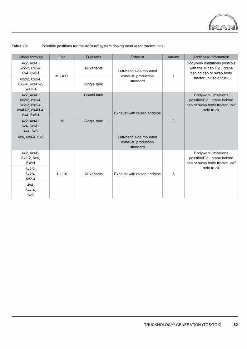
TRUCKNOLOGY® GENERATION (TGS/TGX) 82
Table 23: Possible positions for the AdBlue® system dosing module for tractor units:
Wheel formula Cab Fuel tank Exhaust Variant Additional information4x2, 4x4H,
6x2-2, 6x2-4, 6x4, 6x6H
M - XXL
All variantsLeft-hand side mounted
exhaust, production standard
1
Bodywork limitations possible with the M cab E.g.: crane behind cab or swap body
tractor unit/solo truck6x2/2, 6x2/4, 6x2-4, 6x4H-2,
6x4H-4Single tank
4x2, 4x4H, 6x2/2, 6x2/4, 6x2-2, 6x2-4,
6x4H-2, 6x4H-4, 6x4, 6x6H
M
Combi tank
Exhaust with raised endpipe
3
Bodywork limitations possibleE.g.: crane behind
cab or swap body tractor unit/solo truck
4x2, 4x4H, 6x4, 6x6H, 4x4, 6x6
Single tank
4x4, 6x4-4, 6x6 Left-hand side mounted exhaust, production
standard4x2, 4x4H, 6x2-2, 6x4,
6x6H
L - LX All variants Exhaust with raised endpipe 5
Bodywork limitations possibleE.g.: crane behind
cab or swap body tractor unit/solo truck6x2/2,
6x2/4, 6x2-44x4,
6x4-4, 6x6
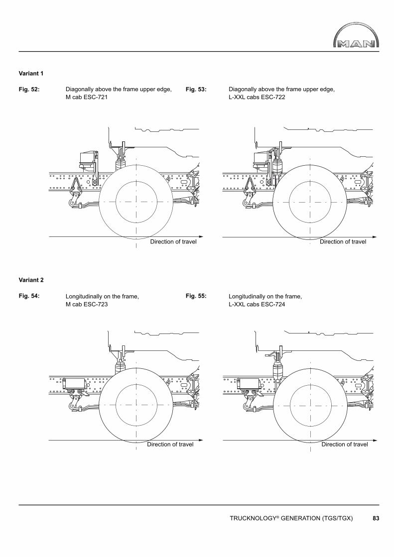
TRUCKNOLOGY® GENERATION (TGS/TGX) 83
Diagonally above the frame upper edge, M cab ESC-721
Longitudinally on the frame, M cab ESC-723
Diagonally above the frame upper edge, L-XXL cabs ESC-722
Longitudinally on the frame, L-XXL cabs ESC-724
Direction of travel Direction of travel
Direction of travel Direction of travel
Variant 1
Fig. 52: Fig. 53:
Variant 2
Fig. 54: Fig. 55:
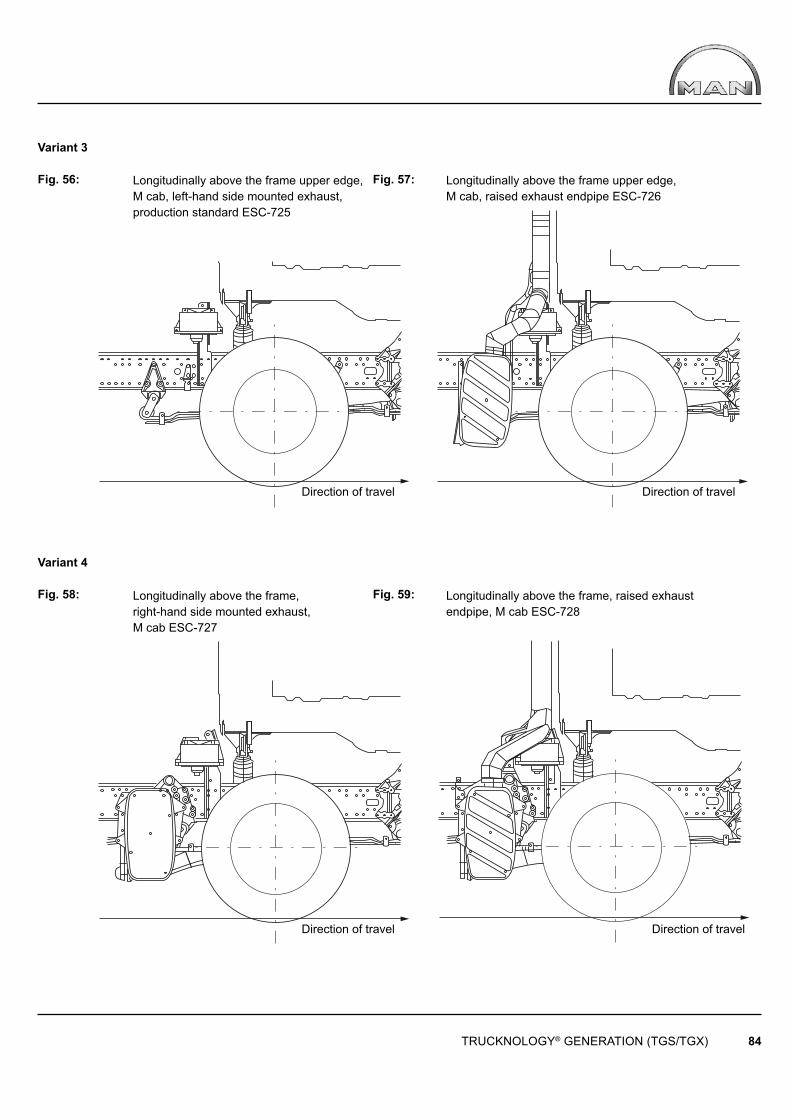
TRUCKNOLOGY® GENERATION (TGS/TGX) 84
Longitudinally above the frame upper edge, M cab, left-hand side mounted exhaust, production standard ESC-725
Longitudinally above the frame, right-hand side mounted exhaust,M cab ESC-727
Longitudinally above the frame upper edge, M cab, raised exhaust endpipe ESC-726
Longitudinally above the frame, raised exhaust endpipe, M cab ESC-728
Direction of travel Direction of travel
Direction of travel Direction of travel
Variant 3
Fig. 56: Fig. 57:
Variant 4
Fig. 58: Fig. 59:
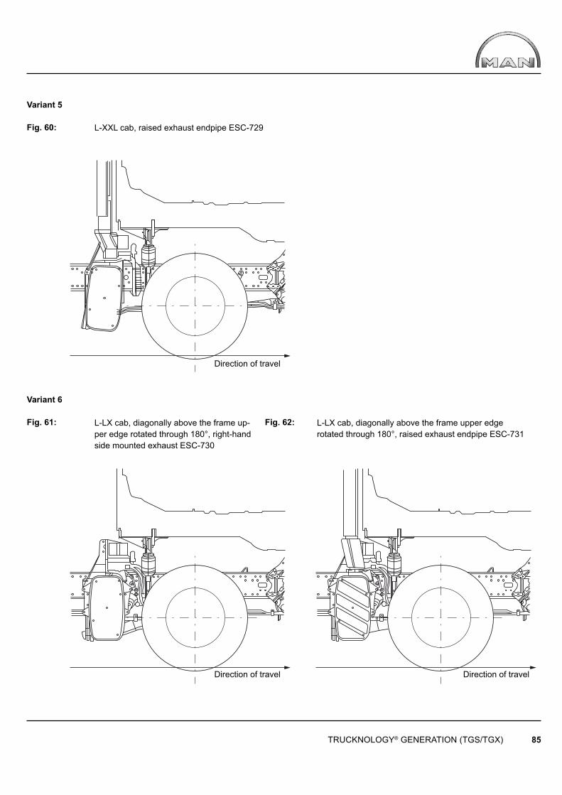
TRUCKNOLOGY® GENERATION (TGS/TGX) 85
L-XXL cab, raised exhaust endpipe ESC-729
L-LX cab, diagonally above the frame up-per edge rotated through 180°, right-hand side mounted exhaust ESC-730
L-LX cab, diagonally above the frame upper edge rotated through 180°, raised exhaust endpipe ESC-731
Direction of travel Direction of travel
Direction of travel
Variant 5
Fig. 60:
Variant 6
Fig. 61: Fig. 62:
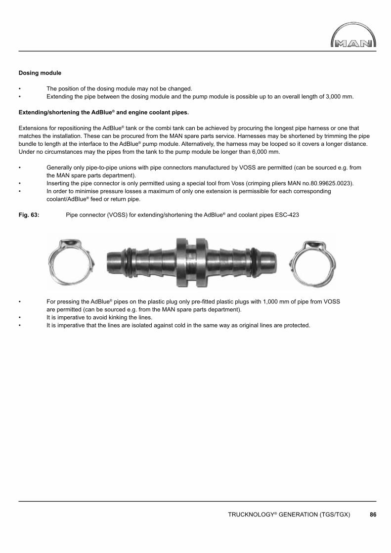
TRUCKNOLOGY® GENERATION (TGS/TGX) 86
Dosing module
• The position of the dosing module may not be changed.• Extending the pipe between the dosing module and the pump module is possible up to an overall length of 3,000 mm.
Extending/shortening the AdBlue® and engine coolant pipes.
Extensions for repositioning the AdBlue® tank or the combi tank can be achieved by procuring the longest pipe harness or one that matches the installation. These can be procured from the MAN spare parts service. Harnesses may be shortened by trimming the pipe bundle to length at the interface to the AdBlue® pump module. Alternatively, the harness may be looped so it covers a longer distance. Under no circumstances may the pipes from the tank to the pump module be longer than 6,000 mm.
• Generally only pipe-to-pipe unions with pipe connectors manufactured by VOSS are permitted (can be sourced e.g. from the MAN spare parts department).• Inserting the pipe connector is only permitted using a special tool from Voss (crimping pliers MAN no.80.99625.0023).• In order to minimise pressure losses a maximum of only one extension is permissible for each corresponding coolant/AdBlue® feed or return pipe.
Fig. 63: Pipe connector (VOSS) for extending/shortening the AdBlue® and coolant pipes ESC-423
• For pressing the AdBlue® pipes on the plastic plug only pre-fitted plastic plugs with 1,000 mm of pipe from VOSS are permitted (can be sourced e.g. from the MAN spare parts department).• It is imperative to avoid kinking the lines.• It is imperative that the lines are isolated against cold in the same way as original lines are protected.
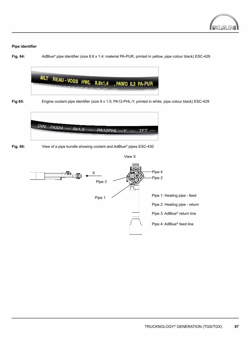
TRUCKNOLOGY® GENERATION (TGS/TGX) 87
X
View X
Pipe 3
Pipe 1
Pipe 2Pipe 4
Pipe 1: Heating pipe - feed
Pipe 2: Heating pipe - return
Pipe 3: AdBlue® return line
Pipe 4: AdBlue® feed line
Pipe identifi er Fig. 64: AdBlue® pipe identifier (size 8.8 x 1.4; material PA-PUR, printed in yellow, pipe colour black) ESC-428
Fig 65: Engine coolant pipe identifier (size 9 x 1.5; PA12-PHL-Y, printed in white, pipe colour black) ESC-429
Fig. 66: View of a pipe bundle showing coolant and AdBlue® pipes ESC-430

TRUCKNOLOGY® GENERATION (TGS/TGX) 88
Dosing moduleInjection nozzle
AdBlue®
intake lineDosing line
AdBlue®
runback line Compressed-air line
Air supply
AdBlue® TankCombinend
delivery dosingmodule
Injectionnozzle
Fig. 67: Temperature sensor, injection nozzle, dosing module ESC-424
For Euro 6 vehicles the following applies in addition to the lower emission standard requirements:
In contrast to Euro 5 vehicles the Euro 6 AdBlue® system is arranged as follows:
Fig. 68: Schematic overview of the AdBlue® system in Euro 6 vehicles ESC-419a
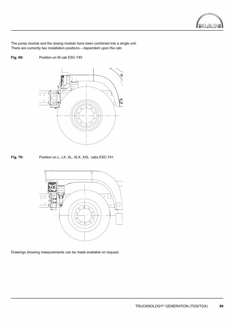
TRUCKNOLOGY® GENERATION (TGS/TGX) 89
The pump module and the dosing module have been combined into a single unit. There are currently two installation positions – dependent upon the cab:
Fig. 69: Position on M cab ESC-740
Fig. 70: Position on L, LX, XL, XLX, XXL cabs ESC-741
Drawings showing measurements can be made available on request.
TRUCKNOLOGY® GENERATION (TGS/TGX) 90
Moving the pump module or the AdBlue® tank is currently not possible.
If the standard AdBlue® tank is replaced with a container of greater or smaller capacity, then the vehicle must be re-parameterised. Only those AdBlue® tanks may be installed that are available as a factory option for the relevant vehicle. In addition to the tank, all other components of the AdBlue® system must be adapted correspondingly.
Additional cut-off valves in the AdBlue® pipes are inadmissible. Plug-in connections on the ends of the pipes may only be replaced with plug-in connections that are approved by the factory. (Part numbers can be obtained from the spare parts service). The pipes may not be kinked or compressed. The pipe cross section may not be modifi ed under any circumstances.
The AdBlue® pipes must be protected against the airstream. The insulation fi tted at the factory may not be removed or modifi ed. The AdBlue® pipes must be protected against temperatures of over 50°. The feed line of the heating circuit may not be bundled with the other pipes.
4.12.4 Engine cooling
• The cooling system (radiator, grille, air ducts, coolant circuit) may not be modifi ed.• Exceptions only with the approval of MAN (for address see “Publisher” above). • Modifi cations to the radiator that reduce the cooling surface cannot be approved.• The cooling system may be only be fi lled using coolants approved by MAN in accordance with the information given in the service fi ll fl uid database.• Materials that contain copper may not be used in the cooling circuit.
Under following conditions, a radiator of modifi ed performance may be required:
• Operating primarily under stationary conditions • Operating in climatically unfavorable zones (areas with severe climates)• Operating in areas where it can be expected that the cooling performance may be reduced e.g. due to a high dust level
The nearest MAN sales centre can provide information on delivery options for the respective vehicle; for retrofit installation, contact the nearest MAN service centre or MAN authorised workshop. When fi tting a third-party radiator, the requirements set forth in the installation guideline for installed engines must be observed. This guideline can be obtained from MAN (for address see „Publisher“ above).

TRUCKNOLOGY® GENERATION (TGS/TGX) 91
4.12.5 Engine encapsulation, noise insulation
Work on and modifi cations to factory-fi tted engine encapsulation are not permitted. If vehicles are defi ned as „low-noise“, they will lose this status if retrofi t work has been carried out on them. The company that has carried out the modifi cation will then be responsible for re-obtaining the previous status.
4.13 Fitting other manual gearboxes, automatic transmissions and transfer boxes
Fitting manual or automatic transmissions that have not been documented by MAN is not possible because there is no interface to the CAN powertrain. If non-documented manual or automatic transmissions are fi tted malfunctions may occur in safety-relevant electronic systems. Fitting third-party transfer boxes (e.g. for use as power take-offs) impacts the powertrain electronics.On vehicles fi tted with mechanical manual transmissions it may, under certain circumstances, be possible to adapt the system by parameterisation. Consult MAN (for address see “Publisher” above) before any work is commenced.It is not permitted to install these units to vehicles fi tted with MAN TipMatic / ZF ASTRONIC (ZF12AS transmissions).
5. Bodies
5.1 General
For identifi cation purposes, each body must be fi tted with a model plate that must contain the following data as a minimum:
• Full name of body manufacturer• Serial number.
The plates must have a minimum height of 4 mm.
The data must be marked permanently on the model plate.Applicable standards regarding the securing of loads on commercial vehicles, in Europe EN 12640 (lashing points), 12641 (tarpaulins) and 12642 (body structure) are to be observed, if requested compliance with these standards must be ensured, e.g. by adding a relevant clause to the purchase contract. Bodies have a significant influence on the vehicle’s handling characteristics and drag, and consequently also on fuel consumption. Bodies must therefore not unnecessarily increase drag or negatively affect the vehicle’s handling characteristics. The unavoidable bending and twisting of the frame should not cause any undesirable characteristics in either the body or the vehicle. The body and chassis must be able to absorb such forces safely. The approximate value for permissible bending can be calculated as follows:
Formula 16: Approximate value for permissible bending
i Σ1 li + lü f = 200
TRUCKNOLOGY® GENERATION (TGS/TGX) 92
Where: f = Maximum bending, in [mm] li = Wheelbases, Σ li = sum of the wheelbases, in [mm] lü = Frame overhang, in [mm]
The body should transfer as few vibrations as possible to the chassis. We assume that bodybuilders should at the very least be able to determine approximate ratings for the subframe and assembly. It is also expected that suitable measures are taken to prevent vehicle overloading. The unavoidable tolerances and hystereses arising in vehicle design must also be taken into consideration.
These include, for example:
• the tyres• the springs (including hysteresis in air suspension systems) • the frame
When the vehicle is in operation, other dimensional changes will occur. These include:
• settling of the springs• tyre deformation• body deformation.
The frame must not be deformed before or during installation. Before positioning the vehicle for installation, it should be drivenbackwards and forwards a few times to release any trapped stresses. This applies particularly to vehicles fitted with more than 2 axles due to the axle stiffness that occurs when cornering. The vehicle should be placed on a level surface to install the body. Frame height differences on the left/right of ≤ 1.5% of the ground-to- frame upper edge distance are within the limits of the hysteresis and settling effects outlined above. The body must be able to sustain such differences which should not be compensated by frame alignment, spring inserts or by adjusting the air suspension level because these will inevitably change during operation. Variations > 1.5% must be notified, before any repairs are carried out, to the MAN customer services department which will decide which measures are to be taken by the bodybuilder and/or the MAN service centre. Accessibility, Clearances: Access to the filler necks for AdBlue® fuel and further service fi ll fl uids using petrol pump nozzle must be ensured, by corresponding body cut-outs, if required. This applies in particular to bodies without a subframe and to bodies with low substructure height. Accessibility to any components attached to the frame (e.g. spare wheel lift, battery box) must not be impeded by the body.
The freedom of movement of moving parts in relation to the body must not be adversely affected.
For example:
• Brake cylinders• Gearchange mechanism (gear linkage, cable-controlled gearshift)• Axle mounting components• Intarder pipework
To ensure minimum clearances the following should be taken into account:
• Maximum compression of the springs • Dynamic compression during the journey• Compression when starting off or braking• Side tilt when cornering• Operation with anti-skid chains• Limp-home mode characteristics, for example damage to an air spring bellows during a journey and the resulting side tilt (e.g. 3° side tilt to ISO 1726 on tractor units see also the ‘Coupling devices TG’ booklet).
Despite wheel guards it is still possible for dirt, stones, sand etc., to be thrown up against the body, particularly during „off-road“ use. Body structures must therefore be suitably protected (e.g. by fi tting protective grilles or applying a resistant coating).

TRUCKNOLOGY® GENERATION (TGS/TGX) 93
5.1.1 Machinery Directive (2006/42/EC)
The Machinery Directive can be obtained from EUR-Lex at the following link:
http://eur-lex.europa.eu/LexUriServ/LexUriServ.do?uri=OJ:L:2006:157:0024:0086:DE:PDF or http://eur-lex.europa.eu
GeneralThe Machinery Directive serves to ensure the health and safety of persons, in particular of employees, consumers and objects, in particular in relation to the risks inherent whilst using machinery.
It sets forth generally applicable, fundamental health and safety protection requirements in accordance with the state of the art at the time of design, together with technical and commercial requirements that are supplemented by a range of specifi c requirements for certain classes of machine.
There is an appropriate procedure for every type of machine with which compliance with the underlying health and safety protection requirements can be checked. These include the conformity assessment procedures, the CE conformity markings and a risk assessment. Furthermore, the manufacturer must prepare technical documentation for each machine.
Scope of application
In addition to the Guide to Fitting Bodies, bodybuilders must also observe the Machinery Directive. The Machinery Directive is fundamentally not applicable to the truck‘s chassis because the applicable statutory requirements are defi ned in the Directive on type-approval of motor vehicles and their trailers (70/156/EEC).The Machinery Directive does however, apply to a range of bodies. The products (truck bodies) that fall under this scope of application are defi ned in Article 1 of the Machinery Directive (scope of application).
The Machinery Directive applies fundamentally to:
• Machines• Interchangeable equipment• Safety-related components• Load suspension devices• Chains, ropes and straps• Removable driveshafts• Incomplete machines
Examples include:
• Loading cranes• Liftgates (tail-lifts)• Tipper bodies• Flushing and suction bodies• Recovery platform bodies• Compressors fi tted to the body• Mechanically driven cable winches• Roll-off and set-down skip loader bodies• Aerial work platforms• Tanker bodies
TRUCKNOLOGY® GENERATION (TGS/TGX) 94
Among others, exceptions include:
• Agricultural and forestry tractor units• Vehicles and vehicle trailers (70/156/EWG)
If such a product (body/mounted equipment) is mounted onto the truck chassis, then the Machinery Directive applies not to the truck chassis, but to the body that is mounted upon it. The Machinery Directive also applies to the interfaces between the truck chassis and the body that are responsible for the safe movement and operation of the machine. This is why it is necessary to differentiate between self-propelled agricultural machines (which fall fully under the Machinery Directive) and truck chassis with bodywork that includes or is mounted with machinery.
Examples of self-propelled agricultural machines include:
• Self-propelled construction machines• Concrete pumps• Mobile cranes• Gully emptiers• Drilling rig carrier vehicles
Defi nition of machinery in accordance with 2006/42/EC
— „an assembly, fi tted with or intended to be fi tted with a drive system other than directly applied human or animal effort, consisting of linked parts or components, at least one of which moves, and which are joined together for a specifi c application;
— an assembly referred to in the fi rst indent, missing only the components to connect it on site or to sources of energy and motion;
— an assembly referred to in the fi rst and second indents, ready to be installed and able to function as it stands only if mounted on a means of transport, or installed in a building or a structure;
— assemblies of machinery referred to in the fi rst, second and third indents or partly completed machinery referred to in point (g) which, in order to achieve the same end, are arranged and controlled so that they function as an integral whole;
— an assembly of linked parts or components, at least one of which moves and which are joined together, intended for lifting loads and whose only power source is directly applied human effort;“
Source: Excerpt from 2006/42/EC
TRUCKNOLOGY® GENERATION (TGS/TGX) 95
5.1.2 CE marking (CE conformity marking in accordance with 2006/42/EC)
The bodybuilder shall ensure that the superstructure, along with its attachments and accessories, complies with the statutory requirements. The Machinery Directive (2006/42/EC) sets forth the types of machinery that require CE marking.
The following apply fundamentally to the superstructure:
• All machinery must carry the CE mark. I.e. this includes all safety-relevant components, removable driveshafts, chains, cables and straps.• Incomplete machines may not carry a CE mark.
For the CE marking of machinery, the following applies:
• The CE marking shall be affi xed to the machinery visibly, legibly and indelibly.• The affi xing on machinery of markings, signs and inscriptions that are likely to mislead third parties as to the meaning or form of the CE marking, or both, shall be prohibited. • Any other marking may be affi xed to the machinery provided that the visibility, legibility and meaning of the CE marking is not thereby impaired.• In order to ensure the same quality for the CE marking and the manufacturer‘s mark, it is important that they be affi xed according to the same techniques. In order to avoid confusion between any CE markings which might appear on certain components and the CE marking corresponding to the machinery, it is important that the latter marking be affi xed alongside the name of the person who has taken responsibility for it, namely the manufacturer or his authorised representative.• It is prohibited to pre-date or post-date the date of manufacture of the machinery when affi xing the CE marking.• If the CE marking is reduced or enlarged the proportions shown in the drawing reproduced here must be maintained.• The various components of the CE marking must have approximately the same vertical dimensions, which may not be less than 5 mm. The minimum dimension may be waived for small-scale machinery.
The CE conformity marking shall consist of the initials „CE“ taking the following form:
Where machinery is also the subject of other Directives relating to other aspects and providing for the affi xing of the CE marking, the marking shall indicate that the machinery also conforms to the provisions of those other Directives. However, where one or more of those Directives allow the manufacturer or his authorised representative to choose, during a transitional period, the system to be applied, the CE marking shall indicate conformity only to the provisions of those Directives applied by the manufacturer or his authorised representative. Particulars of the Directives applied, as published in the Offi cial Journal of the European Union, shall be given on the EC declaration of conformity. Where the full quality assurance procedure referred to in Article 12(3)(c) and 12(4)(b) has been applied, the CE marking must be followed by the identifi cation number of the notifi ed body.
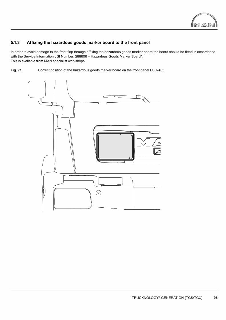
TRUCKNOLOGY® GENERATION (TGS/TGX) 96
5.1.3 Affi xing the hazardous goods marker board to the front panel
In order to avoid damage to the front fl ap through affi xing the hazardous goods marker board the board should be fi tted in accordance with the Service Information „ SI Number: 288606 – Hazardous Goods Marker Board“. This is available from MAN specialist workshops.
Fig. 71: Correct position of the hazardous goods marker board on the front panel ESC-485
TRUCKNOLOGY® GENERATION (TGS/TGX) 97
5.2 Corrosion protection
Surface and corrosion protection affects the service life and appearance of the product. In general, the quality of the coatings on body components should be equal to that of the chassis.
To ensure this requirement is met, the MAN Works Standard M 3297 „Corrosion protection and coating systems for non-MAN bodies“ is binding for bodies that are ordered by MAN. If the customer commissions the body, this standard becomes a recommendation only. Should the standard not be observed, MAN provides no guarantee for any consequences.MAN-works standards may be obtained from www.normen.man-nutzfahrzeuge.de (registration required).Series production MAN chassis are coated with environmentally friendly, water-based 2-component chassis top-coat paints at approx. 80°C. To guarantee uniform coating, the following coating structure is required for all metal component assemblies on the body and subframe and, following frame modifi cations, on the chassis:
• Bare metal or blasted component surface (SA 2.5)• Primer coat: 2-component epoxy primer, or if possible cathodic dip painting to MAN works standard M 3078-2, with zinc phosphate pre-treatment• Top coat: 2-component top-coat paint to MAN works standard M 3094, preferably water-based; if there are no facilities for this, then solvent-based paint is also permitted (www.normen.man-nutzfahrzeuge.de, registration required).
Instead of a primer and top coat, the substructure of the body (e.g. longitudinal members, cross members and corner plates) galvanising may also be used. See the relevant data sheets from the paint manufacturer for information on tolerances for drying and curing times and temperatures. When selecting and combining different metals (e.g. aluminium and steel) the effect of the electrochemical series on the occurrence of corrosion at the boundary surfaces must be taken into consideration (insulation). The compatibility of materials must also be taken into consideration.
After all work on the chassis has been completed:
• Remove any drilling swarf• Remove burrs from the edges• Apply wax preservative to any cavities.
Mechanical connections (e.g. bolts, nuts, washers, pins) that have not been painted over must be given optimum corrosionProtection.
To prevent salt corrosion whilst the vehicle is stationary during the body-building phase all chassis must be washed with clean water to remove any salt residues as soon as they arrive at the body manufacturer.
5.3 Subframes
5.3.1 General
Should a subframe be required it must be of a continuous design, it may not be interrupted or bent out to the side (exceptions e.g. for some types of tipper, require approval). No moving parts may be restricted in their freedom of movement by the subframe structure.
5.3.2 Permissible materials, yield points
The yield point, also called elongation limit or σ0,2 limit, must not be exceeded under any driving or load conditions. The safety coeffi cients must be taken into account. See table 24 for the yield points for different subframe materials.
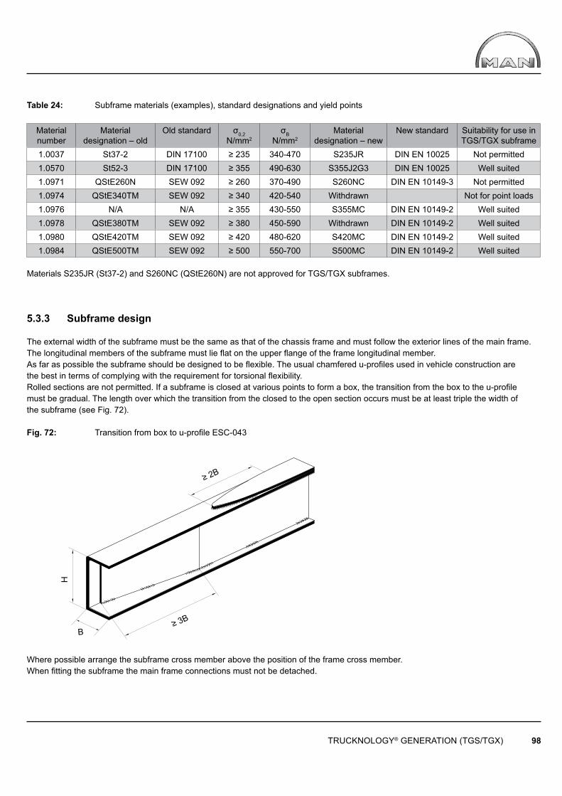
TRUCKNOLOGY® GENERATION (TGS/TGX) 98
≥ 2B
≥ 3B
H
B
Table 24: Subframe materials (examples), standard designations and yield points
Material number
Material designation – old
Old standard σ0,2N/mm2
σBN/mm2
Material designation – new
New standard Suitability for use in TGS/TGX subframe
1.0037 St37-2 DIN 17100 ≥ 235 340-470 S235JR DIN EN 10025 Not permitted1.0570 St52-3 DIN 17100 ≥ 355 490-630 S355J2G3 DIN EN 10025 Well suited1.0971 QStE260N SEW 092 ≥ 260 370-490 S260NC DIN EN 10149-3 Not permitted1.0974 QStE340TM SEW 092 ≥ 340 420-540 Withdrawn Not for point loads1.0976 N/A N/A ≥ 355 430-550 S355MC DIN EN 10149-2 Well suited1.0978 QStE380TM SEW 092 ≥ 380 450-590 Withdrawn DIN EN 10149-2 Well suited1.0980 QStE420TM SEW 092 ≥ 420 480-620 S420MC DIN EN 10149-2 Well suited1.0984 QStE500TM SEW 092 ≥ 500 550-700 S500MC DIN EN 10149-2 Well suited
Materials S235JR (St37-2) and S260NC (QStE260N) are not approved for TGS/TGX subframes.
5.3.3 Subframe design
The external width of the subframe must be the same as that of the chassis frame and must follow the exterior lines of the main frame. The longitudinal members of the subframe must lie flat on the upper flange of the frame longitudinal member.As far as possible the subframe should be designed to be flexible. The usual chamfered u-profiles used in vehicle construction are the best in terms of complying with the requirement for torsional flexibility.Rolled sections are not permitted. If a subframe is closed at various points to form a box, the transition from the box to the u-profilemust be gradual. The length over which the transition from the closed to the open section occurs must be at least triple the width of the subframe (see Fig. 72).
Fig. 72: Transition from box to u-profi le ESC-043
Where possible arrange the subframe cross member above the position of the frame cross member.When fi tting the subframe the main frame connections must not be detached.

A B
TRUCKNOLOGY® GENERATION (TGS/TGX) 99
Detail A Detail BMounting holes
Recess Ø 40
Avoid diagoal welds at the frame bends
Provide cross-members at thebends in the frame
All drillings on the subframe-frame-cross-member connection drilled to Ø 14,5 and reamed to Ø 16 + 0,3
On each side, the middle bolt that sup-ports the frame connection must be left in place
If the subframe is shorter than the frame round-off here R = 0,5 subframe thickness
Fig. 73: Subframe design ESC-096
The subframe longitudinal member must reach as far forward as possible – at least beyond the rearmost front spring hanger.For an air-sprung 1st axle we recommend a clearance of ≤ 600mm between the wheel centre of the 1st axle and the subframe.
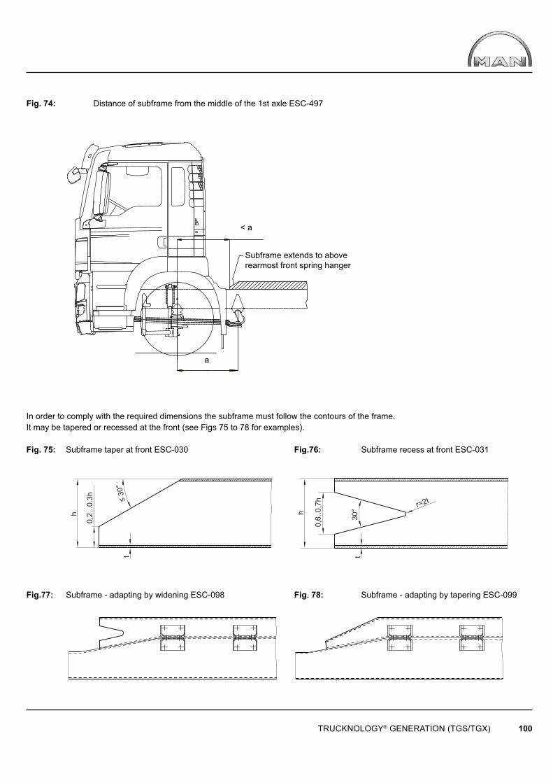
875.0002
< a
a
0,2.
..0.3
h
≤ 30
° t
h
t
r=2t
h
0,6.
.0,7
h
30°
TRUCKNOLOGY® GENERATION (TGS/TGX) 100
Subframe extends to above rearmost front spring hanger
Fig. 74: Distance of subframe from the middle of the 1st axle ESC-497
In order to comply with the required dimensions the subframe must follow the contours of the frame. It may be tapered or recessed at the front (see Figs 75 to 78 for examples).
Fig. 75: Subframe taper at front ESC-030 Fig.76: Subframe recess at front ESC-031
Fig.77: Subframe - adapting by widening ESC-098 Fig. 78: Subframe - adapting by tapering ESC-099
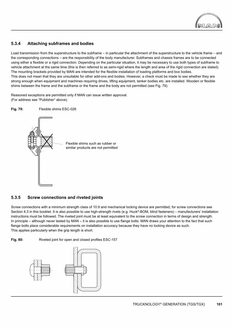
TRUCKNOLOGY® GENERATION (TGS/TGX) 101
Flexible shims such as rubber or similar products are not permitted
5.3.4 Attaching subframes and bodies
Load transmission from the superstructure to the subframe – in particular the attachment of the superstructure to the vehicle frame – and the corresponding connections – are the responsibility of the body manufacturer. Subframes and chassis frames are to be connected using either a fl exible or a rigid connection. Depending on the particular situation, it may be necessary to use both types of subframe to vehicle attachment at the same time (this is then referred to as semi-rigid where the length and area of the rigid connection are stated).The mounting brackets provided by MAN are intended for the fl exible installation of loading platforms and box bodies. This does not mean that they are unsuitable for other add-ons and bodies. However, a check must be made to see whether they are strong enough when equipment and machines requiring drives, lifting equipment, tanker bodies etc. are installed. Wooden or fl exible shims between the frame and the subframe or the frame and the body are not permitted (see Fig. 79).
Reasoned exceptions are permitted only if MAN can issue written approval.(For address see “Publisher“ above).
Fig. 79: Flexible shims ESC-026
5.3.5 Screw connections and riveted joints
Screw connections with a minimum strength class of 10.9 and mechanical locking device are permitted, for screw connections see Section 4.3 in this booklet. It is also possible to use high-strength rivets (e.g. Huck®-BOM, blind fasteners) – manufacturers’ installation instructions must be followed. The riveted joint must be at least equivalent to the screw connection in terms of design and strength.In principle – although never tested by MAN – it is also possible to use fl ange bolts. MAN draws your attention to the fact that such fl ange bolts place considerable requirements on installation accuracy because they have no locking device as such. This applies particularly when the grip length is short. Fig. 80: Riveted joint for open and closed profi les ESC-157
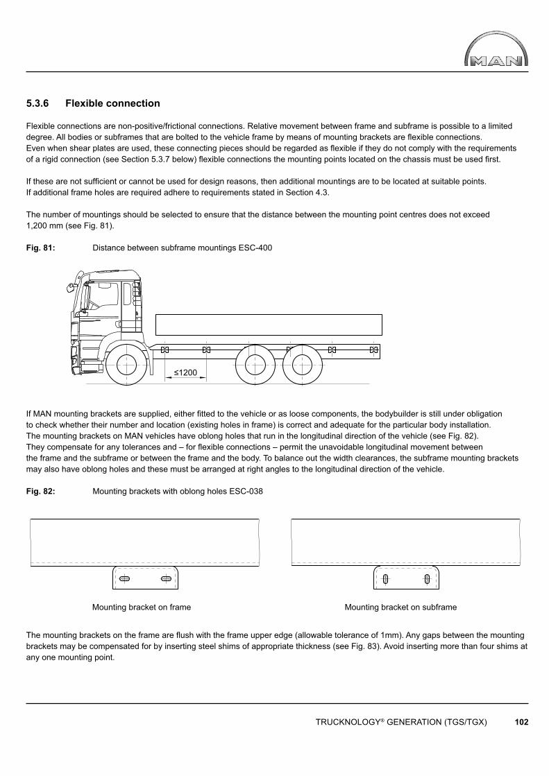
≤1200
TRUCKNOLOGY® GENERATION (TGS/TGX) 102
Mounting bracket on frame Mounting bracket on subframe
5.3.6 Flexible connection
Flexible connections are non-positive/frictional connections. Relative movement between frame and subframe is possible to a limited degree. All bodies or subframes that are bolted to the vehicle frame by means of mounting brackets are fl exible connections. Even when shear plates are used, these connecting pieces should be regarded as fl exible if they do not comply with the requirements of a rigid connection (see Section 5.3.7 below) fl exible connections the mounting points located on the chassis must be used fi rst.
If these are not suffi cient or cannot be used for design reasons, then additional mountings are to be located at suitable points.If additional frame holes are required adhere to requirements stated in Section 4.3.
The number of mountings should be selected to ensure that the distance between the mounting point centres does not exceed 1,200 mm (see Fig. 81).
Fig. 81: Distance between subframe mountings ESC-400
If MAN mounting brackets are supplied, either fi tted to the vehicle or as loose components, the bodybuilder is still under obligation to check whether their number and location (existing holes in frame) is correct and adequate for the particular body installation.The mounting brackets on MAN vehicles have oblong holes that run in the longitudinal direction of the vehicle (see Fig. 82).They compensate for any tolerances and – for fl exible connections – permit the unavoidable longitudinal movement between the frame and the subframe or between the frame and the body. To balance out the width clearances, the subframe mounting brackets may also have oblong holes and these must be arranged at right angles to the longitudinal direction of the vehicle.
Fig. 82: Mounting brackets with oblong holes ESC-038
The mounting brackets on the frame are flush with the frame upper edge (allowable tolerance of 1mm). Any gaps between the mounting brackets may be compensated for by inserting steel shims of appropriate thickness (see Fig. 83). Avoid inserting more than four shims at any one mounting point.
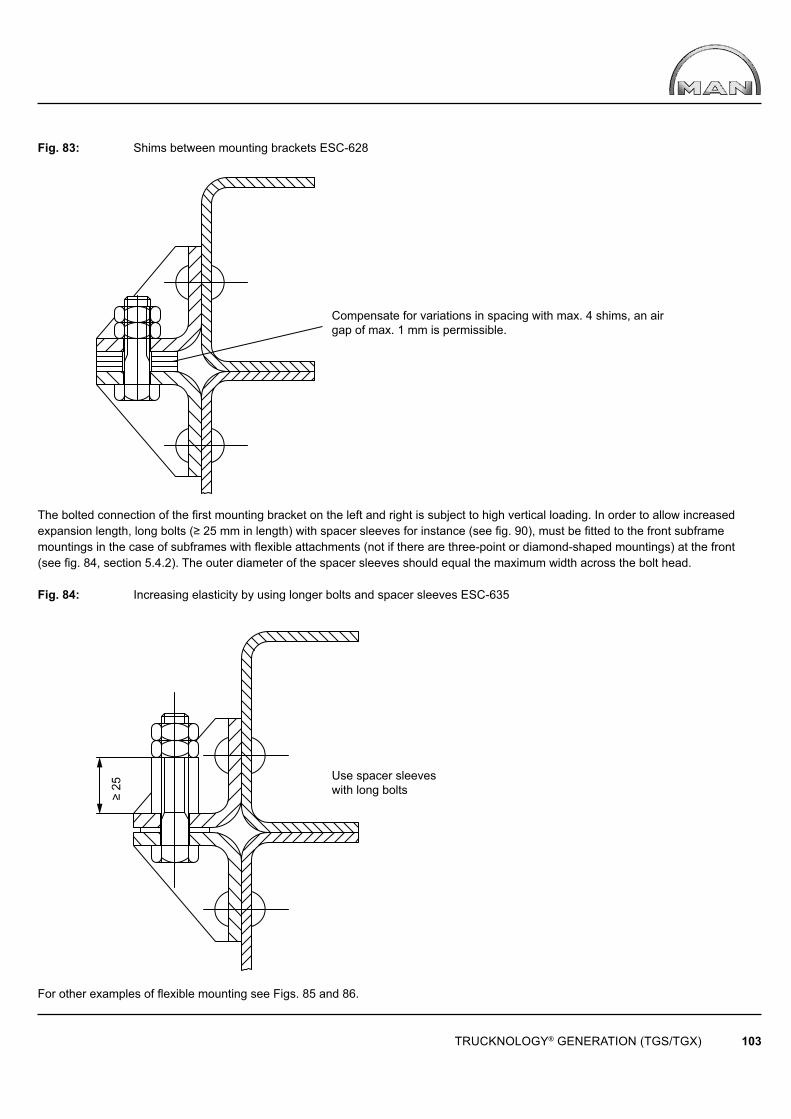
TRUCKNOLOGY® GENERATION (TGS/TGX) 103
Compensate for variations in spacing with max. 4 shims, an air gap of max. 1 mm is permissible.
Use spacer sleeves with long bolts≥ 25
Fig. 83: Shims between mounting brackets ESC-628
The bolted connection of the fi rst mounting bracket on the left and right is subject to high vertical loading. In order to allow increased expansion length, long bolts (≥ 25 mm in length) with spacer sleeves for instance (see fi g. 90), must be fi tted to the front subframe mountings in the case of subframes with fl exible attachments (not if there are three-point or diamond-shaped mountings) at the front (see fi g. 84, section 5.4.2). The outer diameter of the spacer sleeves should equal the maximum width across the bolt head.
Fig. 84: Increasing elasticity by using longer bolts and spacer sleeves ESC-635
For other examples of fl exible mounting see Figs. 85 and 86.
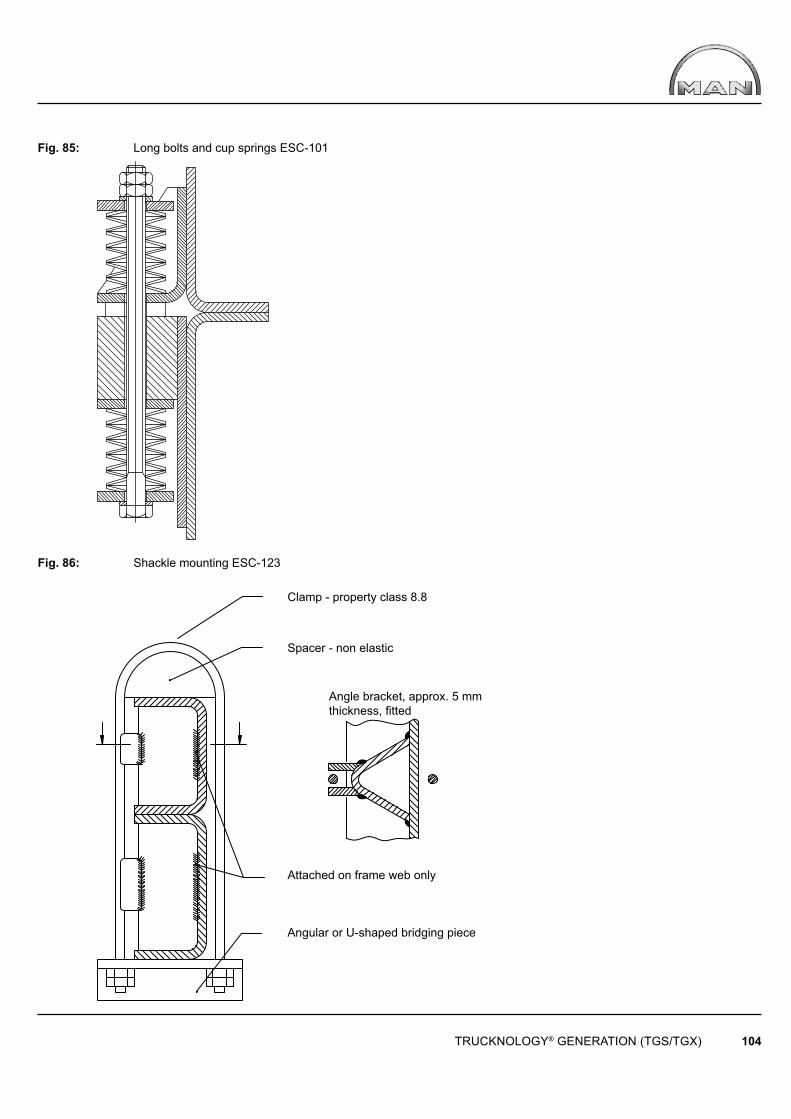
TRUCKNOLOGY® GENERATION (TGS/TGX) 104
Clamp - property class 8.8
Spacer - non elastic
Attached on frame web only
Angular or U-shaped bridging piece
Angle bracket, approx. 5 mm thickness, fi tted
Fig. 85: Long bolts and cup springs ESC-101
Fig. 86: Shackle mounting ESC-123

TRUCKNOLOGY® GENERATION (TGS/TGX) 105
5.3.7 Rigid connection
With rigid connections relative movement between the frame and subframe is no longer possible, the subframe follows all the movements of the frame. If the connection is rigid the frame and the subframe profi le in the vicinity of the rigid connection are regarded as one single section for calculation purposes. Mounting brackets supplied ex-works and other connections that are non-positive/frictional are not considered to be rigid connections. Only positive-locking connecting elements are rigid.
Positive-locking connecting elements are rivets or bolts. However, bolts are only classed rigid connectors if a hole tolerance of ≤ 0.2 mm is maintained. If rigid connections are to be made using solid-shank bolts then the bolt’s thread may not come into contact with the bolt hole walls (see Fig. 87). The minimum grade for bolts is 10.9.
Fig. 87: Contact of the bolt thread with the hole wall ESC-029
Due to the short grip lengths that are normally required, use may be made of spacer sleeves as shown in Fig. 88.
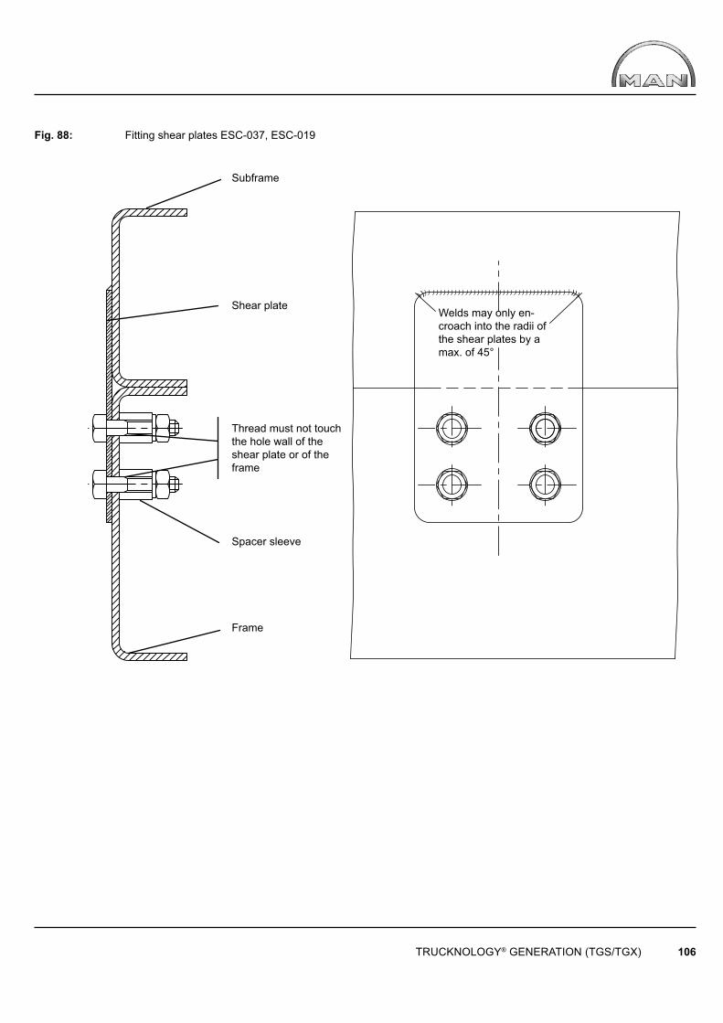
TRUCKNOLOGY® GENERATION (TGS/TGX) 106
Subframe
Shear plate
Spacer sleeve
Frame
Thread must not touch the hole wall of the shear plate or of the frame
Welds may only en-croach into the radii of the shear plates by a max. of 45°
Fig. 88: Fitting shear plates ESC-037, ESC-019
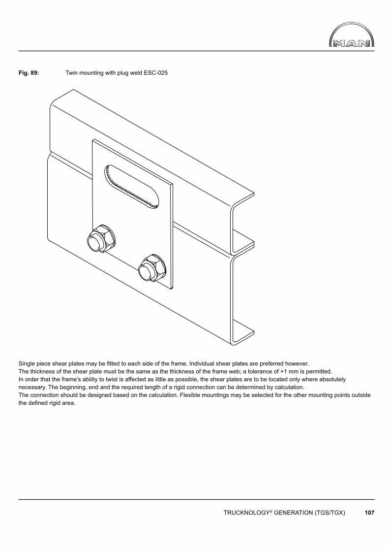
TRUCKNOLOGY® GENERATION (TGS/TGX) 107
Fig. 89: Twin mounting with plug weld ESC-025
Single piece shear plates may be fi tted to each side of the frame. Individual shear plates are preferred however.The thickness of the shear plate must be the same as the thickness of the frame web; a tolerance of +1 mm is permitted. In order that the frame’s ability to twist is affected as little as possible, the shear plates are to be located only where absolutely necessary. The beginning, end and the required length of a rigid connection can be determined by calculation. The connection should be designed based on the calculation. Flexible mountings may be selected for the other mounting points outside the defi ned rigid area.

TRUCKNOLOGY® GENERATION (TGS/TGX) 108
5.4 Bodies
5.4.1 Testing of bodies
Testing of bodies and subsequent approval in writing at MAN (for address see “Publisher” above) is required when deviations have been made from this Guide to Fitting Bodies and the deviation has been made for valid technical reasons. For the calculations, two copies of body documentation that must be suitable for inspection are required. This documentation must contain the following information in addition to a drawing of the body:
→ Identifi cation of the deviations from the Guide to Fitting Bodies in all documentation!
• Loads and their load application points: - Loads applied by the body - Axle load calculation• Special conditions of use:• Subframe: - Material and cross-sectional data - Dimensions - Type of section - Arrangement of cross members in the subframe - Special features of the subframe design - Cross-section modifi cations - Additional reinforcements - Upsweeps, etc.• Means of connection: - Positioning (in relation to the chassis) - Type - Size - Number.
Photos, 3D pictures and perspective drawings may be used for purposes of clarity but they may not replace the binding documentation set out above.
5.4.2 Platform and box bodies
To ensure even load distribution on the chassis a subframe is normally used.Consideration should be given to wheel clearances as early as during the body design stage – including the lowered position/chassis position at full suspension compression. Additional clearance requirements for items such as anti-skid chains, vehicle body roll, degree of axle articulation must also be taken into account. Hinged vehicle sides may not contact the road surface even when the vehicle is in the lowered position or the chassis position is at full suspension compression. The body must sit torsion free on the longitudinal frame members.
Closed bodies in particular, such as box bodies, are designed to be relatively torsionally stiff with respect to the chassis frame. So that the desired twisting of the frame (for example when cornering) is not hindered by the body, the body fi xtures should be fl exible at the front and rigid at the rear. This is particularly important if the vehicle is designed for off-road purposes. For this application, we recommend a front body mount with a three-point or diamond-shaped mounting (see Fig. 90 for mounting principle).
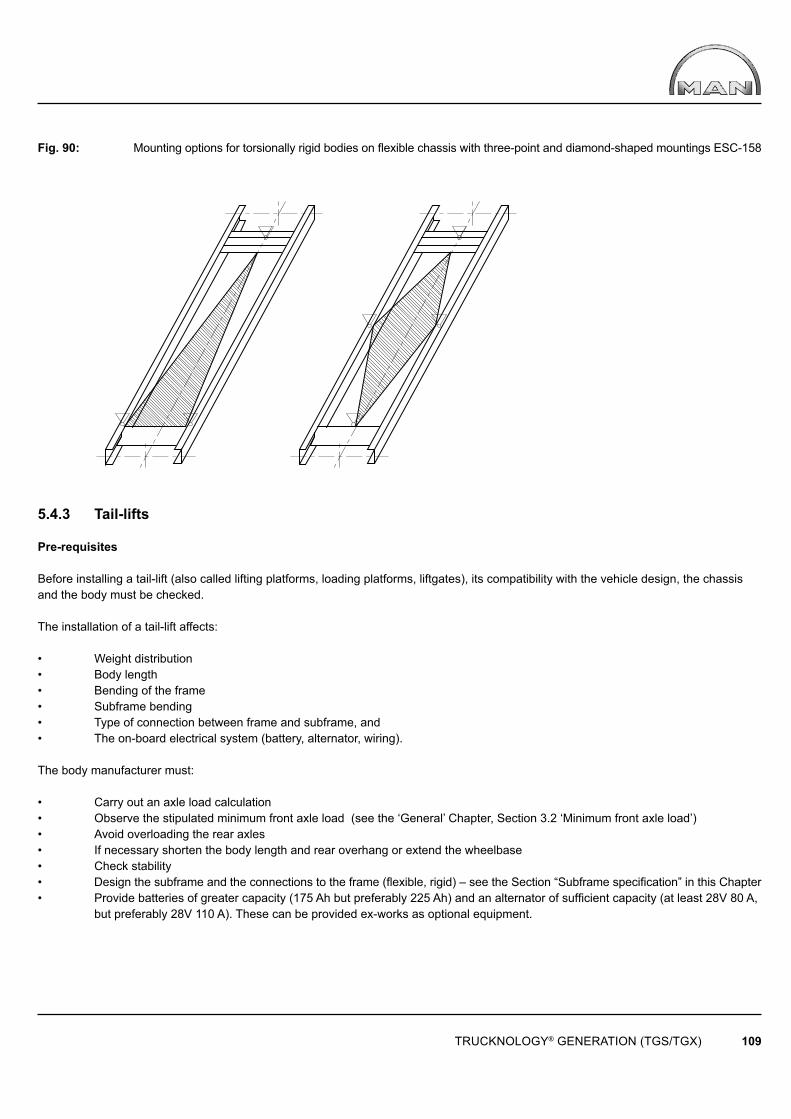
TRUCKNOLOGY® GENERATION (TGS/TGX) 109
Fig. 90: Mounting options for torsionally rigid bodies on fl exible chassis with three-point and diamond-shaped mountings ESC-158
5.4.3 Tail-lifts
Pre-requisites
Before installing a tail-lift (also called lifting platforms, loading platforms, liftgates), its compatibility with the vehicle design, the chassis and the body must be checked.
The installation of a tail-lift affects:
• Weight distribution• Body length • Bending of the frame• Subframe bending• Type of connection between frame and subframe, and• The on-board electrical system (battery, alternator, wiring).
The body manufacturer must:
• Carry out an axle load calculation• Observe the stipulated minimum front axle load (see the ‘General’ Chapter, Section 3.2 ‘Minimum front axle load’)• Avoid overloading the rear axles• If necessary shorten the body length and rear overhang or extend the wheelbase• Check stability• Design the subframe and the connections to the frame (fl exible, rigid) – see the Section “Subframe specifi cation” in this Chapter• Provide batteries of greater capacity (175 Ah but preferably 225 Ah) and an alternator of suffi cient capacity (at least 28V 80 A, but preferably 28V 110 A). These can be provided ex-works as optional equipment.

TRUCKNOLOGY® GENERATION (TGS/TGX) 110
• Install an electrical interface for the tail-lift (available ex-works as optional equipment; for wiring diagrams and pin assignment see the Section on electrical connections). • Observe statutory regulations, e.g.: - EC Machinery Directive (consolidated version of Directive 89/392/EEC: 98/37/EC) - Accident prevention regulations - Fit an underride guard - Fit approved lighting installations in accordance with 76/756/EEC (in Germany, additional yellow indicator lights and retrorefl ective red-white warning markers are also required when operating the tail-lift, in accordance with §53b, Paragraph 5, StVZO for lifting platforms).
Defi ning the sub-frame
The sub-frame tables are applicable subject to the following:
• Minimum front axle load respected in accordance with Section 3.2 of the ‚General’ Chapter• No design overload of the rear axle(s)• In addition to the support loads occurring on the tail-lift, both minimum front axle load and maximum rear axle load are to be added to the trailer vehicle on testing.• Vehicles with lifting axles must lower the lifting axle during operation of the tail-lift.• Overhang limits in respect of max. vehicle overhang must be respected.
The values in the tables are the benchmark values for which, due to strength/deformation reasons, no outriggers are required.
They are only required if:
- The tail-lift loading capacity limits given in the tables is exceeded - Outriggers are required for stability reasons
If outriggers – although not required – are fi tted, this does not affect the size of the extended sub-frame. It is not permitted to raise the vehicle on the outriggers, as this could damage the frame.
The tables are sorted in ascending order according to tonnage class, variant description, suspension type and wheelbase, where the vehicle designation (e.g. TGS 18.xxx 4x2 BB, TGX 26.xxx 6x2-2 BL) is to be regarded as an aid to orientation. The 3-digit type numbers, also known as type code numbers, which appear at the 2nd and 4th positions of the basic vehicle number and at the 4th and 6th positions of the vehicle identifi cation number are binding (for explanation, see the ‘General’ Chapter). All other technical documents, e.g. chassis drawings, assembly directives relate to the type number.The overhang – always related to the wheel centre of the last axle – includes both the frame overhang of thestandard production chassis and the overall maximum vehicle overhang (including body and tail-lift, see Fig. 89 below),which must not be exceeded when the tail-lift has been fi tted. If the specifi ed maximum vehicle overhang is insuffi cient,the sub-frame data in the following lines for which the ≤-condition is satisfi ed applies (apart from the start of the rigidconnection, which relates only to the wheelbase).The sub-frames in the tables are examples. For instance U120/60/6 is a U section open to the inside with an outer height of 120 mm, top and bottom 60 mm wide and 6 mm thick over the entire cross section.Other steel sections are acceptable if they have at least equivalent values in respect of the moment of inertia Ix, moments of resistance Wx1 Wx2 and yield point σ0,2.
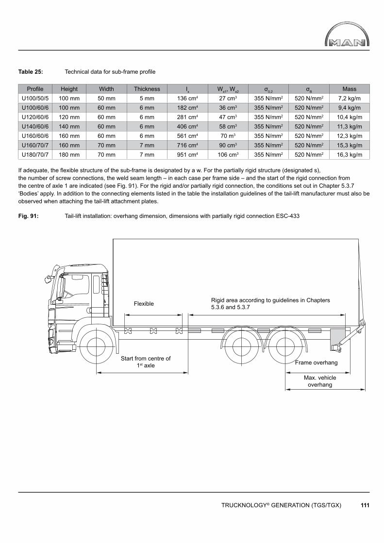
TRUCKNOLOGY® GENERATION (TGS/TGX) 111
Rigid area according to guidelines in Chapters 5.3.6 and 5.3.7Flexible
Start from centre of 1st axle Frame overhang
Max. vehicle overhang
Table 25: Technical data for sub-frame profi le
Profi le Height Width Thickness Ix Wx1, Wx2 σ0,2 σB MassU100/50/5 100 mm 50 mm 5 mm 136 cm4 27 cm3 355 N/mm2 520 N/mm2 7,2 kg/mU100/60/6 100 mm 60 mm 6 mm 182 cm4 36 cm3 355 N/mm2 520 N/mm2 9,4 kg/mU120/60/6 120 mm 60 mm 6 mm 281 cm4 47 cm3 355 N/mm2 520 N/mm2 10,4 kg/mU140/60/6 140 mm 60 mm 6 mm 406 cm4 58 cm3 355 N/mm2 520 N/mm2 11,3 kg/mU160/60/6 160 mm 60 mm 6 mm 561 cm4 70 m3 355 N/mm2 520 N/mm2 12,3 kg/mU160/70/7 160 mm 70 mm 7 mm 716 cm4 90 cm3 355 N/mm2 520 N/mm2 15,3 kg/mU180/70/7 180 mm 70 mm 7 mm 951 cm4 106 cm3 355 N/mm2 520 N/mm2 16,3 kg/m
If adequate, the flexible structure of the sub-frame is designated by a w. For the partially rigid structure (designated s),the number of screw connections, the weld seam length – in each case per frame side – and the start of the rigid connection fromthe centre of axle 1 are indicated (see Fig. 91). For the rigid and/or partially rigid connection, the conditions set out in Chapter 5.3.7‘Bodies’ apply. In addition to the connecting elements listed in the table the installation guidelines of the tail-lift manufacturer must also be observed when attaching the tail-lift attachment plates.
Fig. 91: Tail-lift installation: overhang dimension, dimensions with partially rigid connection ESC-433
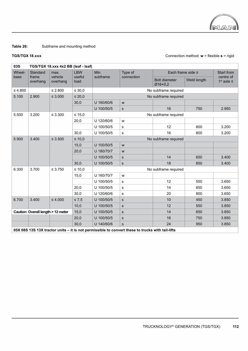
TRUCKNOLOGY® GENERATION (TGS/TGX) 112
Table 26: Subframe and mounting method
TGS/TGX 18.xxx Connection method: w = fl exible s = rigid
03S TGS/TGX 18.xxx 4x2 BB (leaf - leaf)Wheel-base
Standard frame overhang
max. vehicle overhang
LBWusefulload
Min. subframe
Type of connection
Each frame side ≥ Start fromcentre of 1st axle ≤Bolt diameter
Ø16+0,2Weld length
≤ 4.800 ≤ 2.800 ≤ 30,0 No subframe required5.100 2.900 ≤ 3.000 ≤ 20,0 No subframe required
30,0 U 160/60/6 wU 100/50/5 s 16 750 2.950
5.500 3.200 ≤ 3.300 ≤ 15,0 No subframe required20,0 U 120/60/6 w
U 100/50/5 s 12 600 3.20030,0 U 100/50/5 s 16 800 3.200
5.900 3.400 ≤ 3.500 ≤ 10,0 No subframe required15,0 U 100/50/5 w20,0 U 180/70/7 w
U 100/50/5 s 14 650 3.40030,0 U 100/50/5 s 18 850 3.400
6.300 3.700 ≤ 3.750 ≤ 10,0 No subframe required15,0 U 160/70/7 w
U 100/50/5 s 12 550 3.65020,0 U 100/50/5 s 14 650 3.65030,0 U 120/60/6 s 20 800 3.650
6.700 3.400 ≤ 4.000 ≤ 7,5 U 100/50/5 s 10 450 3.85010,0 U 100/50/5 s 12 550 3.850
Caution: Overall length > 12 meter 15,0 U 100/50/5 s 14 650 3.85020,0 U 100/50/5 s 16 750 3.85030,0 U 140/60/6 s 24 950 3.850
05X 08S 13S 13X tractor units – it is not permissible to convert these to trucks with tail-lifts
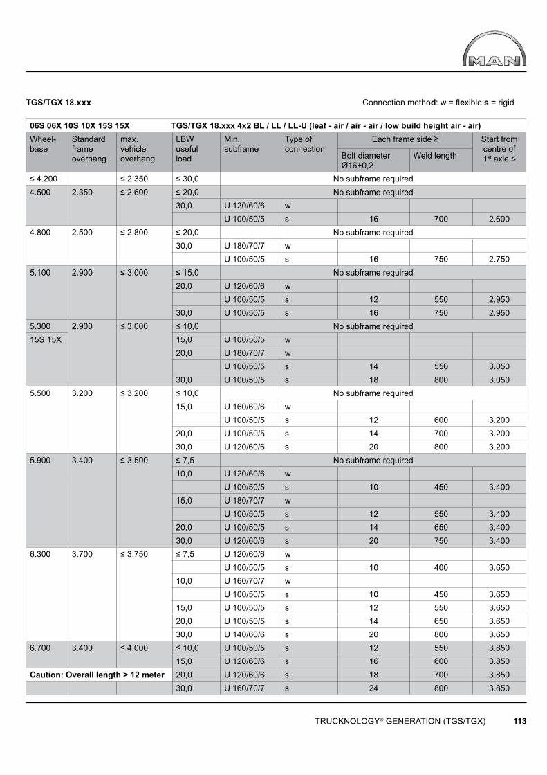
TRUCKNOLOGY® GENERATION (TGS/TGX) 113
TGS/TGX 18.xxx Connection method: w = fl exible s = rigid
06S 06X 10S 10X 15S 15X TGS/TGX 18.xxx 4x2 BL / LL / LL-U (leaf - air / air - air / low build height air - air) Wheel-base
Standard frame overhang
max. vehicle overhang
LBWusefulload
Min. subframe
Type of connection
Each frame side ≥ Start fromcentre of 1st axle ≤Bolt diameter
Ø16+0,2Weld length
≤ 4.200 ≤ 2.350 ≤ 30,0 No subframe required4.500 2.350 ≤ 2.600 ≤ 20,0 No subframe required
30,0 U 120/60/6 wU 100/50/5 s 16 700 2.600
4.800 2.500 ≤ 2.800 ≤ 20,0 No subframe required30,0 U 180/70/7 w
U 100/50/5 s 16 750 2.7505.100 2.900 ≤ 3.000 ≤ 15,0 No subframe required
20,0 U 120/60/6 wU 100/50/5 s 12 550 2.950
30,0 U 100/50/5 s 16 750 2.9505.300 2.900 ≤ 3.000 ≤ 10,0 No subframe required15S 15X 15,0 U 100/50/5 w
20,0 U 180/70/7 wU 100/50/5 s 14 550 3.050
30,0 U 100/50/5 s 18 800 3.0505.500 3.200 ≤ 3.200 ≤ 10,0 No subframe required
15,0 U 160/60/6 wU 100/50/5 s 12 600 3.200
20,0 U 100/50/5 s 14 700 3.20030,0 U 120/60/6 s 20 800 3.200
5.900 3.400 ≤ 3.500 ≤ 7,5 No subframe required10,0 U 120/60/6 w
U 100/50/5 s 10 450 3.40015,0 U 180/70/7 w
U 100/50/5 s 12 550 3.40020,0 U 100/50/5 s 14 650 3.40030,0 U 120/60/6 s 20 750 3.400
6.300 3.700 ≤ 3.750 ≤ 7,5 U 120/60/6 wU 100/50/5 s 10 400 3.650
10,0 U 160/70/7 wU 100/50/5 s 10 450 3.650
15,0 U 100/50/5 s 12 550 3.65020,0 U 100/50/5 s 14 650 3.65030,0 U 140/60/6 s 20 800 3.650
6.700 3.400 ≤ 4.000 ≤ 10,0 U 100/50/5 s 12 550 3.85015,0 U 120/60/6 s 16 600 3.850
Caution: Overall length > 12 meter 20,0 U 120/60/6 s 18 700 3.85030,0 U 160/70/7 s 24 800 3.850
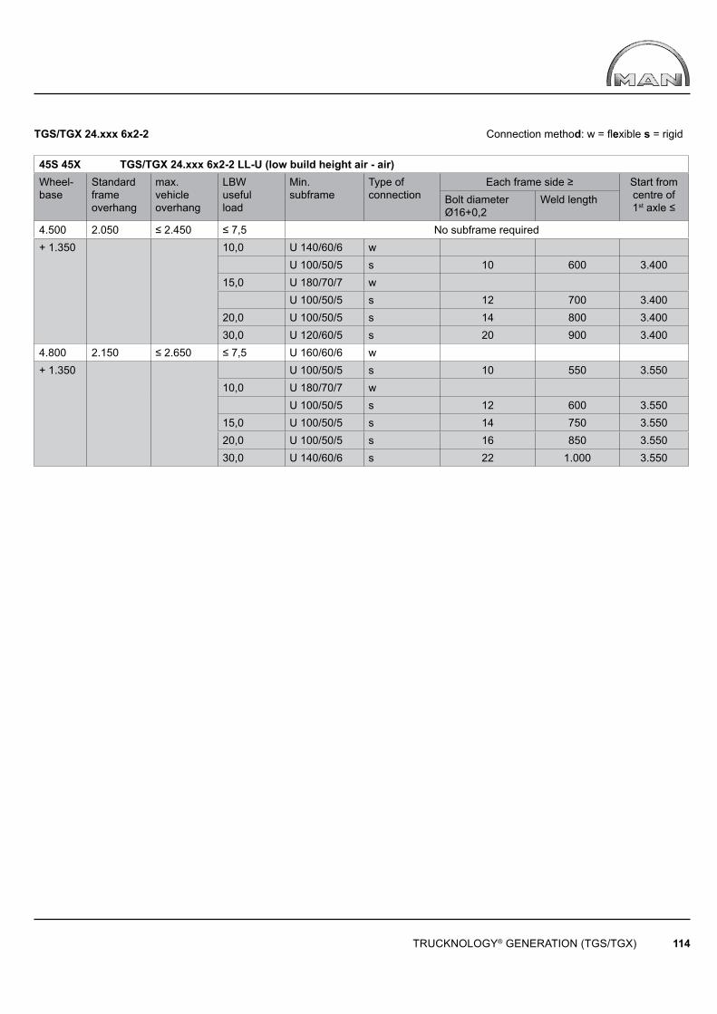
TRUCKNOLOGY® GENERATION (TGS/TGX) 114
TGS/TGX 24.xxx 6x2-2 Connection method: w = fl exible s = rigid
45S 45X TGS/TGX 24.xxx 6x2-2 LL-U (low build height air - air) Wheel-base
Standard frame overhang
max. vehicle overhang
LBWusefulload
Min. subframe
Type of connection
Each frame side ≥ Start fromcentre of 1st axle ≤
Bolt diameterØ16+0,2
Weld length
4.500 2.050 ≤ 2.450 ≤ 7,5 No subframe required+ 1.350 10,0 U 140/60/6 w
U 100/50/5 s 10 600 3.40015,0 U 180/70/7 w
U 100/50/5 s 12 700 3.40020,0 U 100/50/5 s 14 800 3.40030,0 U 120/60/5 s 20 900 3.400
4.800 2.150 ≤ 2.650 ≤ 7,5 U 160/60/6 w+ 1.350 U 100/50/5 s 10 550 3.550
10,0 U 180/70/7 wU 100/50/5 s 12 600 3.550
15,0 U 100/50/5 s 14 750 3.55020,0 U 100/50/5 s 16 850 3.55030,0 U 140/60/6 s 22 1.000 3.550
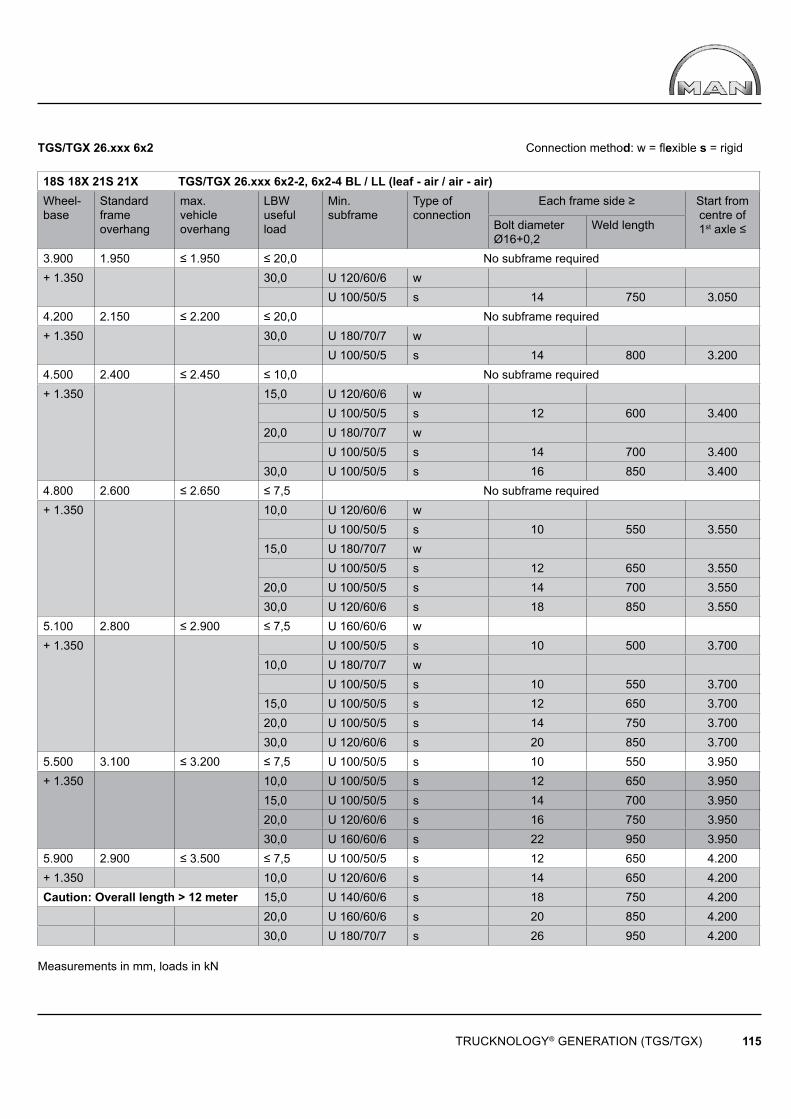
TRUCKNOLOGY® GENERATION (TGS/TGX) 115
TGS/TGX 26.xxx 6x2 Connection method: w = fl exible s = rigid 18S 18X 21S 21X TGS/TGX 26.xxx 6x2-2, 6x2-4 BL / LL (leaf - air / air - air) Wheel-base
Standard frame overhang
max. vehicle overhang
LBWusefulload
Min. subframe
Type of connection
Each frame side ≥ Start fromcentre of 1st axle ≤Bolt diameter
Ø16+0,2Weld length
3.900 1.950 ≤ 1.950 ≤ 20,0 No subframe required+ 1.350 30,0 U 120/60/6 w
U 100/50/5 s 14 750 3.0504.200 2.150 ≤ 2.200 ≤ 20,0 No subframe required+ 1.350 30,0 U 180/70/7 w
U 100/50/5 s 14 800 3.2004.500 2.400 ≤ 2.450 ≤ 10,0 No subframe required+ 1.350 15,0 U 120/60/6 w
U 100/50/5 s 12 600 3.40020,0 U 180/70/7 w
U 100/50/5 s 14 700 3.40030,0 U 100/50/5 s 16 850 3.400
4.800 2.600 ≤ 2.650 ≤ 7,5 No subframe required+ 1.350 10,0 U 120/60/6 w
U 100/50/5 s 10 550 3.55015,0 U 180/70/7 w
U 100/50/5 s 12 650 3.55020,0 U 100/50/5 s 14 700 3.55030,0 U 120/60/6 s 18 850 3.550
5.100 2.800 ≤ 2.900 ≤ 7,5 U 160/60/6 w+ 1.350 U 100/50/5 s 10 500 3.700
10,0 U 180/70/7 wU 100/50/5 s 10 550 3.700
15,0 U 100/50/5 s 12 650 3.70020,0 U 100/50/5 s 14 750 3.70030,0 U 120/60/6 s 20 850 3.700
5.500 3.100 ≤ 3.200 ≤ 7,5 U 100/50/5 s 10 550 3.950+ 1.350 10,0 U 100/50/5 s 12 650 3.950
15,0 U 100/50/5 s 14 700 3.95020,0 U 120/60/6 s 16 750 3.95030,0 U 160/60/6 s 22 950 3.950
5.900 2.900 ≤ 3.500 ≤ 7,5 U 100/50/5 s 12 650 4.200+ 1.350 10,0 U 120/60/6 s 14 650 4.200Caution: Overall length > 12 meter 15,0 U 140/60/6 s 18 750 4.200
20,0 U 160/60/6 s 20 850 4.20030,0 U 180/70/7 s 26 950 4.200
Measurements in mm, loads in kN

TRUCKNOLOGY® GENERATION (TGS/TGX) 116
Disconnect standard plug connector and connect the cab-tail-lift cable harness in between!
Legende
A100 255 Central electrics boxA302 352 Central computer 2A358 Control unit – tail-liftA403 339 Vehicle management computerA407 342 Instrumentation
F219 118 Tail-lift fuse (pin 15)
H254 Tail-lift warning lamp
K175 281 Starter interlock relayK467 281 Tail-lift relay
S286 547 Tail-lift switch
X669 Plug connector, starter interlockX744 Plug connector, tail-liftX2541 246 Potential distributor 21 pin, lead 31000X2542 246 Potential distributor 21 pin, lead 58000X3186 Plug connector, tail-lift
Leads 91003, 91336, 91556, 91557, 91572 and 91573 lead to a 7 pin connector housing on the frame end (rolled up).
Electrical connectionElectro-hydraulic tail-lifts require most careful design of their electrical supply. It is assumed that the information contained in the Chapter‘Electrics, electronics, cables’, of the Guide to Fitting Bodies is applied. Ideally, the electrical interface for the tail-lift should be suppliedex-works (package comprises switches, warning lights, starter inhibitor and power supply for tail-lift). Retrofitting is a complex procedure and requires intervention in the vehicle‘s power supply, which may only be carried out by correspondingly qualified MAN service staff.The factory-fitted transport securing device must be removed. The body manufacturer must check the circuitry of the tail-lift for its compatibility with MAN vehicles. Under normal circumstances triggering of interface A358 may only be effected with 24 V continuous signals – not with fl ash pulses. In case of failure a clocked signal may be applied briefl y to relay K476.
For the tail-lift electric interface see the additional wiring diagram below.
Fig. 92: Additional wiring diagram, tail-lift for MAN no. 81.99192.1920
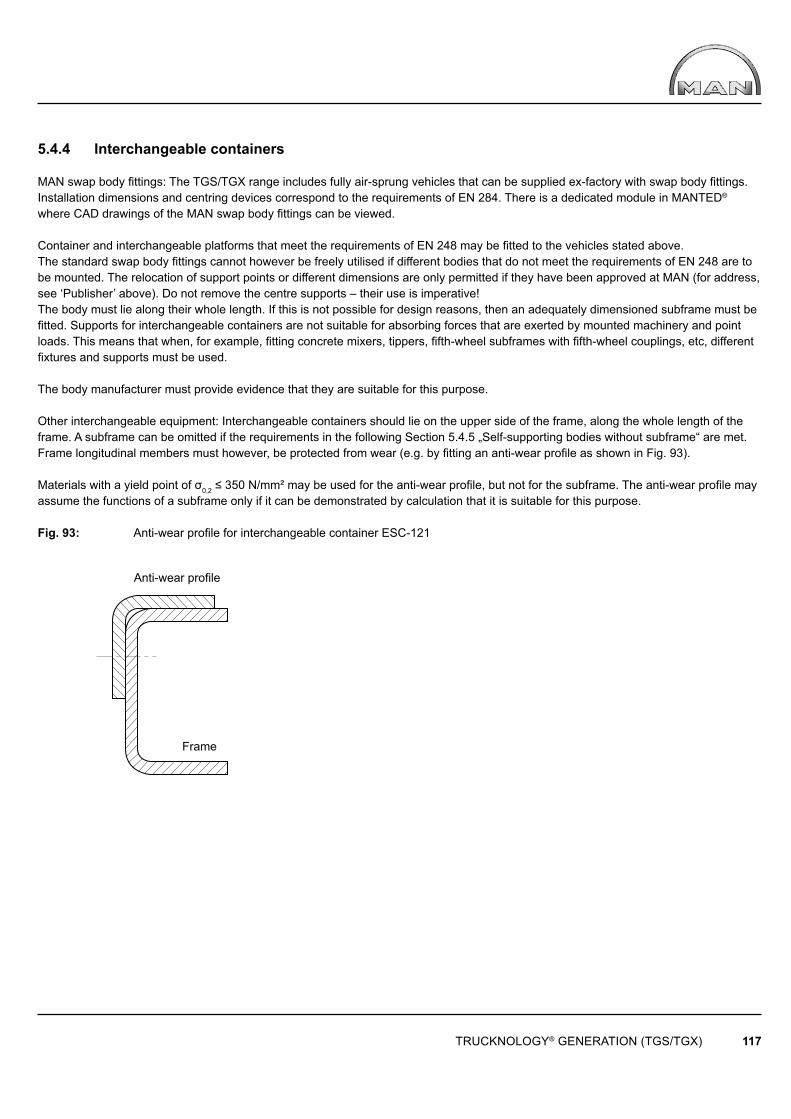
TRUCKNOLOGY® GENERATION (TGS/TGX) 117
Anti-wear profi le
Frame
5.4.4 Interchangeable containers
MAN swap body fi ttings: The TGS/TGX range includes fully air-sprung vehicles that can be supplied ex-factory with swap body fi ttings. Installation dimensions and centring devices correspond to the requirements of EN 284. There is a dedicated module in MANTED® where CAD drawings of the MAN swap body fi ttings can be viewed.
Container and interchangeable platforms that meet the requirements of EN 248 may be fi tted to the vehicles stated above. The standard swap body fi ttings cannot however be freely utilised if different bodies that do not meet the requirements of EN 248 are to be mounted. The relocation of support points or different dimensions are only permitted if they have been approved at MAN (for address, see ‘Publisher’ above). Do not remove the centre supports – their use is imperative! The body must lie along their whole length. If this is not possible for design reasons, then an adequately dimensioned subframe must be fi tted. Supports for interchangeable containers are not suitable for absorbing forces that are exerted by mounted machinery and point loads. This means that when, for example, fi tting concrete mixers, tippers, fi fth-wheel subframes with fi fth-wheel couplings, etc, different fi xtures and supports must be used.
The body manufacturer must provide evidence that they are suitable for this purpose.
Other interchangeable equipment: Interchangeable containers should lie on the upper side of the frame, along the whole length of the frame. A subframe can be omitted if the requirements in the following Section 5.4.5 „Self-supporting bodies without subframe“ are met. Frame longitudinal members must however, be protected from wear (e.g. by fi tting an anti-wear profi le as shown in Fig. 93).
Materials with a yield point of σ0,2 ≤ 350 N/mm² may be used for the anti-wear profi le, but not for the subframe. The anti-wear profi le may assume the functions of a subframe only if it can be demonstrated by calculation that it is suitable for this purpose.
Fig. 93: Anti-wear profi le for interchangeable container ESC-121
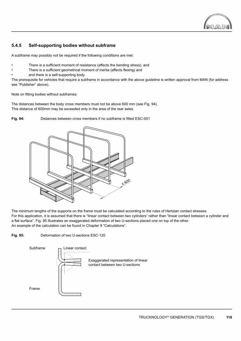
≤ 600
TRUCKNOLOGY® GENERATION (TGS/TGX) 118
Exaggerated representation of linear contact between two U-sections
Subframe Linear contact
Frame
5.4.5 Self-supporting bodies without subframe
A subframe may possibly not be required if the following conditions are met:
• There is a sufficient moment of resistance (affects the bending stress), and• There is a sufficient geometrical moment of inertia (affects flexing) and• and there is a self-supporting body.The prerequisite for vehicles that require a subframe in accordance with the above guideline is written approval from MAN (for address see “Publisher” above).
Note on fi tting bodies without subframes:
The distances between the body cross members must not be above 600 mm (see Fig. 94). This distance of 600mm may be exceeded only in the area of the rear axles.
Fig. 94: Distances between cross members if no subframe is fi tted ESC-001
The minimum lengths of the supports on the frame must be calculated according to the rules of Hertzian contact stresses. For this application, it is assumed that there is “linear contact between two cylinders” rather than “linear contact between a cylinder and a fl at surface”. Fig. 95 illustrates an exaggerated deformation of two U-sections placed one on top of the other.An example of the calculation can be found in Chapter 9 “Calculations“.
Fig. 95: Deformation of two U-sections ESC-120
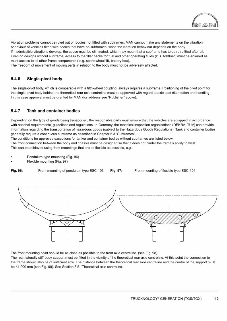
TRUCKNOLOGY® GENERATION (TGS/TGX) 119
Vibration problems cannot be ruled out on bodies not fi tted with subframes. MAN cannot make any statements on the vibration behaviour of vehicles fi tted with bodies that have no subframes, since the vibration behaviour depends on the body.If inadmissible vibrations develop, the cause must be eliminated, which may mean that a subframe has to be retrofi tted after all. Even on designs without subframe, access to the fi ller necks for fuel and other operating fl uids (z.B. AdBlue®) must be ensured as must access to all other frame components ( e.g. spare wheel lift, battery box).The freedom of movement of moving parts in relation to the body must not be adversely affected.
5.4.6 Single-pivot body
The single-pivot body, which is comparable with a fi fth-wheel coupling, always requires a subframe. Positioning of the pivot point for the single-pivot body behind the theoretical rear axle centreline must be approved with regard to axle load distribution and handling. In this case approval must be granted by MAN (for address see “Publisher” above).
5.4.7 Tank and container bodies
Depending on the type of goods being transported, the responsible party must ensure that the vehicles are equipped in accordance with national requirements, guidelines and regulations. In Germany, the technical inspection organisations (DEKRA, TÜV) can provide information regarding the transportation of hazardous goods (subject to the Hazardous Goods Regulations). Tank and container bodies generally require a continuous subframe as described in Chapter 5.3 “Subframes”.The conditions for approved exceptions for tanker and container bodies without subframes are listed below.The front connection between the body and chassis must be designed so that it does not hinder the frame’s ability to twist. This can be achieved using front mountings that are as fl exible as possible, e.g.:
• Pendulum-type mounting (Fig. 96)• Flexible mounting (Fig. 97)
Fig. 96: Front mounting of pendulum type ESC-103 Fig. 97: Front mounting of fl exible type ESC-104
The front mounting point should be as close as possible to the front axle centreline. (see Fig. 98).The rear, laterally stiff body support must be fi tted in the vicinity of the theoretical rear axle centreline. At this point the connection to the frame should also be of suffi cient size. The distance between the theoretical rear axle centreline and the centre of the support must be <1,000 mm (see Fig. 98). See Section 3.5. ‘Theoretical axle centreline.
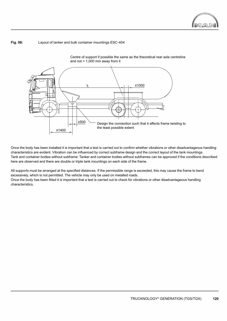
≤1400
lt ≤1000
≥500
TRUCKNOLOGY® GENERATION (TGS/TGX) 120
Centre of support if possible the same as the theoretical rear axle centreline and not > 1,000 mm away from it
Design the connection such that it affects frame twisting to the least possible extent
Fig. 98: Layout of tanker and bulk container mountings ESC-404
Once the body has been installed it is important that a test is carried out to confi rm whether vibrations or other disadvantageous handling characteristics are evident. Vibration can be infl uenced by correct subframe design and the correct layout of the tank mountings.Tank and container bodies without subframe: Tanker and container bodies without subframes can be approved if the conditions described here are observed and there are double or triple tank mountings on each side of the frame.
All supports must be arranged at the specifi ed distances. If the permissible range is exceeded, this may cause the frame to bend excessively, which is not permitted. The vehicle may only be used on metalled roads.Once the body has been fi tted it is important that a test is carried out to check for vibrations or other disadvantageous handling characteristics.
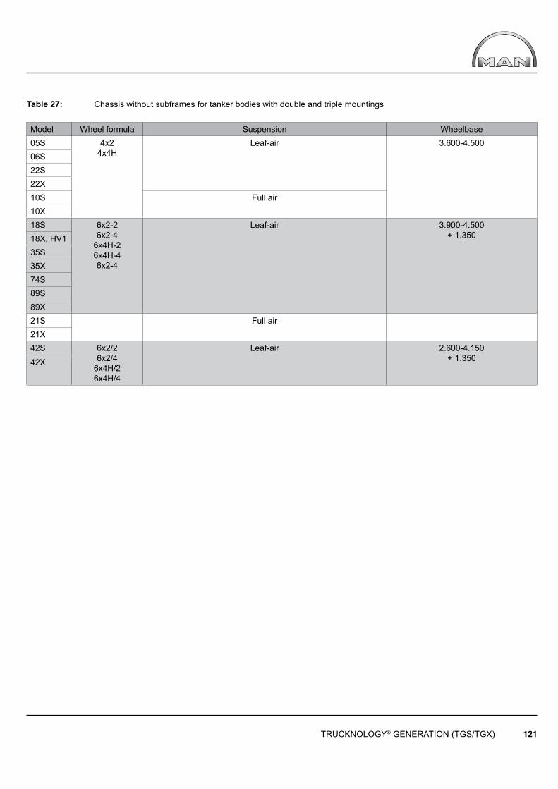
TRUCKNOLOGY® GENERATION (TGS/TGX) 121
Table 27: Chassis without subframes for tanker bodies with double and triple mountings
Model Wheel formula Suspension Wheelbase05S 4x2
4x4HLeaf-air 3.600-4.500
06S22S22X10S Full air10X18S 6x2-2
6x2-46x4H-26x4H-46x2-4
Leaf-air 3.900-4.500 + 1.35018X, HV1
35S35X74S89S89X21S Full air21X42S 6x2/2
6x2/46x4H/26x4H/4
Leaf-air 2.600-4.150 + 1.35042X
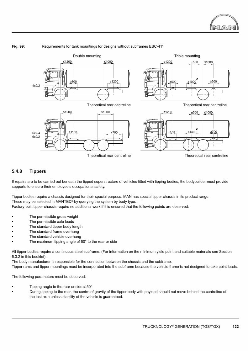
4x2/2
6x2-4 6x2/2
≥700 ≥1100 ≥700 ≥1400 ≥700
≥800
≤1000 ≤1200
≥1200
≤1200 ≤1000 ±500
≤1000≤1200 ≤1200 ≤1000 ±500
≥1000 ≥500 ≥500
TRUCKNOLOGY® GENERATION (TGS/TGX) 122
Double mounting Triple mounting
Theoretical rear centreline Theoretical rear centreline
Theoretical rear centreline Theoretical rear centreline
Fig. 99: Requirements for tank mountings for designs without subframes ESC-411
5.4.8 Tippers
If repairs are to be carried out beneath the tipped superstructure of vehicles fi tted with tipping bodies, the bodybuilder must provide supports to ensure their employee‘s occupational safety.
Tipper bodies require a chassis designed for their special purpose. MAN has special tipper chassis in its product range. These may be selected in MANTED® by querying the system by body type. Factory-built tipper chassis require no additional work if it is ensured that the following points are observed:
• The permissible gross weight • The permissible axle loads • The standard tipper body length• The standard frame overhang• The standard vehicle overhang• The maximum tipping angle of 50° to the rear or side
All tipper bodies require a continuous steel subframe. (For information on the minimum yield point and suitable materials see Section5.3.2 in this booklet). The body manufacturer is responsible for the connection between the chassis and the subframe.Tipper rams and tipper mountings must be incorporated into the subframe because the vehicle frame is not designed to take point loads.
The following parameters must be observed:
• Tipping angle to the rear or side ≤ 50°• During tipping to the rear, the centre of gravity of the tipper body with payload should not move behind the centreline of the last axle unless stability of the vehicle is guaranteed.

S
≤ 5
0o
a
b
TRUCKNOLOGY® GENERATION (TGS/TGX) 123
The centre of gravity of the tipper body must not move behind the centreline of the last axle unless the vehicle is suffi cientls stable
We recommend:
• During the tipping operation, the height of the centre of gravity of the tipper body should not be exceeded. (Dimension “a“ see fi g. 100 ≤ 1.800).• The rear tipper mounting should be located as close as possible to the theoretical rear axle centreline. Recommendation: The distance “b“ (see table 28 and fi g. 100) between the centre of the tipper mountings and theoretical rear axle centreline (1100 mm-1250 mm) should not be exceeded (theoretical rear axle centreline see Section 3.5).
Table 28: Tippers: Maximum values for centre of gravity height and tipper mounting spacing
Chassis Dimension „a“ [mm] Dimension „b“ [mm] Two axle vehicle 4x2, 4x4H u. 4x4 ≤ 1.800 ≤ 1.100
Three axle vehicle x2, 6x4, 6x4H u. 6x6 ≤ 2.000 ≤ 1.250 Four axle vehicle 8x2, 8x4, 8x4H, 8x6, 8x6H u. 8x8 ≤ 2.000 ≤ 1.250
Fig. 100: Tippers: Maximum values for centre of gravity height and tipper mounting spacing ESC-405
For operational safety reasons, operational conditions or when the above stated recommendations are exceeded, further measures may become necessary, such as the use of hydraulic outriggers to increase stability or the relocation of specific equipment.It is however assumed that the bodybuilder recognises the requirement for such measures since they are intrinsically dependent upon the design of his product.
To improve stability and operational safety, rear tippers are sometimes required to be fitted with a so-called scissors-action support and/or a support at the end of the frame (see Fig. 101).
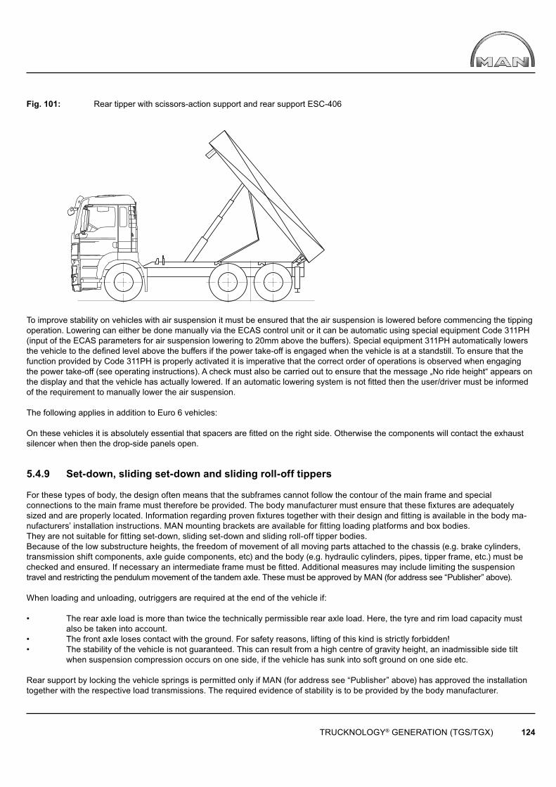
TRUCKNOLOGY® GENERATION (TGS/TGX) 124
Fig. 101: Rear tipper with scissors-action support and rear support ESC-406
To improve stability on vehicles with air suspension it must be ensured that the air suspension is lowered before commencing the tipping operation. Lowering can either be done manually via the ECAS control unit or it can be automatic using special equipment Code 311PH (input of the ECAS parameters for air suspension lowering to 20mm above the buffers). Special equipment 311PH automatically lowers the vehicle to the defi ned level above the buffers if the power take-off is engaged when the vehicle is at a standstill. To ensure that the function provided by Code 311PH is properly activated it is imperative that the correct order of operations is observed when engaging the power take-off (see operating instructions). A check must also be carried out to ensure that the message „No ride height“ appears on the display and that the vehicle has actually lowered. If an automatic lowering system is not fitted then the user/driver must be informed of the requirement to manually lower the air suspension.
The following applies in addition to Euro 6 vehicles:
On these vehicles it is absolutely essential that spacers are fi tted on the right side. Otherwise the components will contact the exhaust silencer when then the drop-side panels open.
5.4.9 Set-down, sliding set-down and sliding roll-off tippers
For these types of body, the design often means that the subframes cannot follow the contour of the main frame and special connections to the main frame must therefore be provided. The body manufacturer must ensure that these fixtures are adequately sized and are properly located. Information regarding proven fixtures together with their design and fitting is available in the body ma-nufacturers’ installation instructions. MAN mounting brackets are available for fitting loading platforms and box bodies. They are not suitable for fi tting set-down, sliding set-down and sliding roll-off tipper bodies.Because of the low substructure heights, the freedom of movement of all moving parts attached to the chassis (e.g. brake cylinders, transmission shift components, axle guide components, etc) and the body (e.g. hydraulic cylinders, pipes, tipper frame, etc.) must be checked and ensured. If necessary an intermediate frame must be fitted. Additional measures may include limiting the suspension travel and restricting the pendulum movement of the tandem axle. These must be approved by MAN (for address see “Publisher” above).
When loading and unloading, outriggers are required at the end of the vehicle if:
• The rear axle load is more than twice the technically permissible rear axle load. Here, the tyre and rim load capacity must also be taken into account.• The front axle loses contact with the ground. For safety reasons, lifting of this kind is strictly forbidden!• The stability of the vehicle is not guaranteed. This can result from a high centre of gravity height, an inadmissible side tilt when suspension compression occurs on one side, if the vehicle has sunk into soft ground on one side etc.
Rear support by locking the vehicle springs is permitted only if MAN (for address see “Publisher” above) has approved the installation together with the respective load transmissions. The required evidence of stability is to be provided by the body manufacturer.

TRUCKNOLOGY® GENERATION (TGS/TGX) 125
To improve stability on vehicles with air suspension it must be ensured that the air suspension is lowered before commencing the tipping operation. Lowering can either be done manually via the ECAS control unit or it can be automatic using special equipment Code 311PH (input of the ECAS parameters for air suspension lowering to 20mm above the buffers). Special equipment 311PH automatically lowers the vehicle to the defi ned level above the buffers if the power take-off is engaged when the vehicle is at a standstill. To ensure that the function provided by Code 311PH is properly activated it is imperative that the correct order of operations is observed when engaging the power take-off (see operating instructions). A check must also be carried out to ensure that the message „No ride height“ appears on the display and that the vehicle has actually lowered. If an automatic lowering system is not fitted then the user/driver must be informed of the requirement to manually lower the air suspension.
5.4.10 Propping air-sprung vehicles
The following must always be observed when propping leaf/air or fully air-sprung vehicles:
The manufacturer of the body is responsible for the stability of the overall system when in working operation.To improve stability on vehicles with air suspension it must be ensured that the air suspension is lowered before commencing the tipping operation. Lowering can either be done manually via the ECAS control unit or it can be automatic using special equipment Code 311PE (input of the ECAS parameters for crane operation). Special equipment 311PE automatically lowers the vehicle onto the buffers if the power take-off is engaged when the vehicle is at a standstill. Once the lowering operation has fi nished the system maintains a defi ned residual pressure in order to protect the air-suspension bellows. To ensure that the function provided by Code 311PE is properly activated it is imperative that the correct order of operations is observed when engaging the power take-off (see operating instructions). A check must also be carried out to ensure that the message „No ride height“ appears on the display and that the vehicle has actually lowered. If an automatic lowering system is not fitted then the user/driver must be informed of the requirement to manually lower the air suspension.Although the complete raising of the axles provides the optimum stability within physical limits, the load that results puts a greater strainon frames and subframes frames. Completely raising the axles as well as lowering the vehicle without special equipment Code 311PE will result in damage to the air-suspension bellows. In order to comply with the specifi cations set forth in the guidelines and to minimise foreseeable misuse/risks, fi tting special equipment Code 311PE is strongly recommended. Exceptions are possible in the case of special purpose vehicles/body designs but this shall be under the bodybuilder‘s sole responsibility and in agreement with the customer.
Note:The functions provided by Codes 311PE / 311PH are deactivated when the engine / power take-off or similar is turned on or off and the standard control laws of the ECAS system activated (setting the air-suspension to ride height). In cases where the vehicle is required to remain for a long period at a set level (lowered position of the air-suspension) it may be necessary to completely suppress the controlling function of the ECAS air-suspension system.Should this be necessary, suppression of the controlling function can be achieved using special equipment 311PK (input of the ECAS parameters with auxiliary circuit for suppressing the automatic levelling suspension system). If this is not already fi tted to the vehicle it can be retrofi tted by a MAN service outlet (for further details see MAN Service Information 239704a).We explicitly point out that this measure does not contribute to stability and is therefore not a means of extending the technical limits of body-mounted equipment (e.g. cranes). The ECAS controlling function may only be suppressed during working operation.
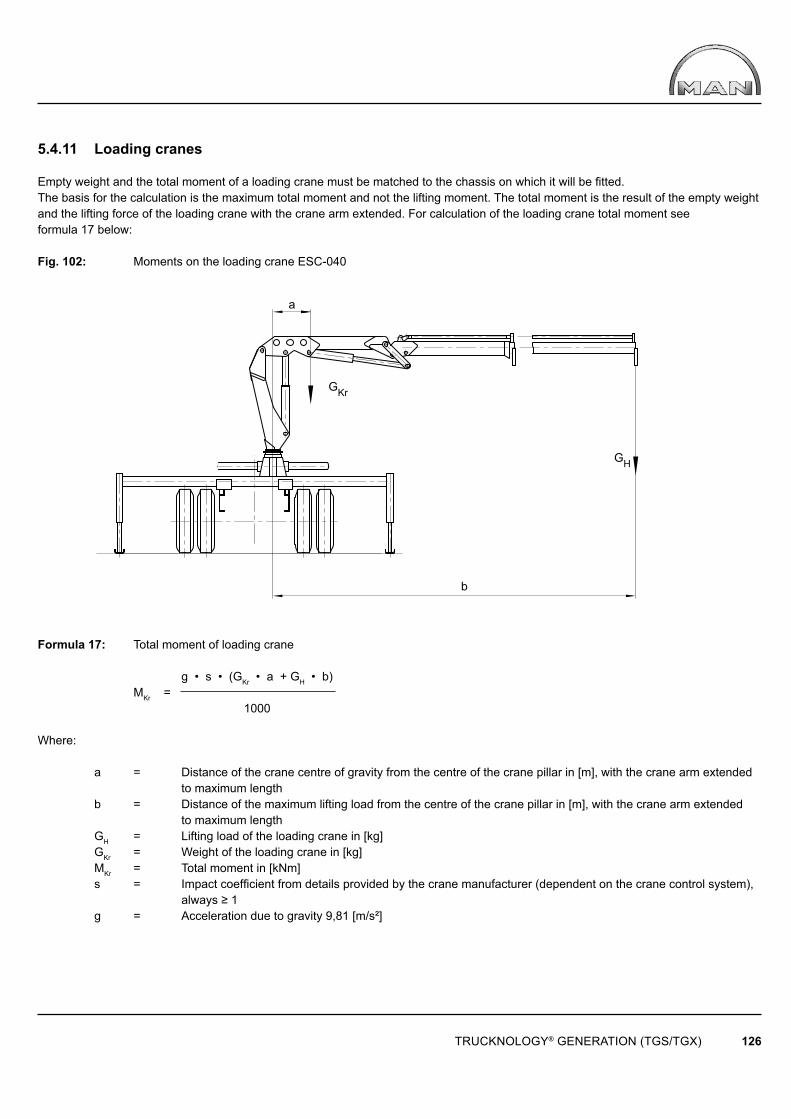
a
GKr
GH
b
TRUCKNOLOGY® GENERATION (TGS/TGX) 126
5.4.11 Loading cranes
Empty weight and the total moment of a loading crane must be matched to the chassis on which it will be fi tted. The basis for the calculation is the maximum total moment and not the lifting moment. The total moment is the result of the empty weight and the lifting force of the loading crane with the crane arm extended. For calculation of the loading crane total moment see formula 17 below:
Fig. 102: Moments on the loading crane ESC-040
Formula 17: Total moment of loading crane
g • s • (GKr • a + GH • b) MKr = 1000
Where:
a = Distance of the crane centre of gravity from the centre of the crane pillar in [m], with the crane arm extended to maximum length b = Distance of the maximum lifting load from the centre of the crane pillar in [m], with the crane arm extended to maximum length GH = Lifting load of the loading crane in [kg] GKr = Weight of the loading crane in [kg] MKr = Total moment in [kNm] s = Impact coeffi cient from details provided by the crane manufacturer (dependent on the crane control system), always ≥ 1 g = Acceleration due to gravity 9,81 [m/s²]
TRUCKNOLOGY® GENERATION (TGS/TGX) 127
The number of outriggers (two or four) and their positions and distance apart is to be determined by the crane manufacturer on the basis of the stability calculation and vehicle load.For technical reasons, MAN may insist that four outriggers are fi tted.When the crane is operating, the outriggers must always be extended and level with the ground. They must be repositioned accordingly for both loading and unloading. Hydraulic compensation between the outriggers must be blocked. The crane manufacturer must also detail any ballast that is required for ensuring stability.Amongst other characteristics, the torsional stiffness of the entire frame connection is responsible for the stability. It must be noted that a high torsional stiffness of the frame connection will necessarily reduce the ride comfort and the off-road capability of the vehicles. The body builder or crane manufacturer is responsible for ensuring that the crane and subframe are properly attached. Operating forces including their safety coeffi cients must be safely absorbed.Mounting brackets available ex-works are not suitable for this purpose. Avoid inadmissible (over)loading of the axle(s).The maximum permissible axle loading during crane operation must not be more than twice the technically permissible axle load. The impact coeffi cients provided by the crane manufacturer must be taken into consideration (see Formula 17)!The permissible axle loads must not be exceeded during vehicle operation, therefore an application-specifi c axle load calculation is essential.Asymmetric installation of a crane is not permissible if uneven wheel loads arise as a result (permissible wheel load difference ≤ 5%, see also Chapter 3.1). The body builder must ensure adequate compensation.The pivoting range of the crane must be limited if this is required to maintain the permissible axle loads or stability. Methods for ensuring this compliance are the responsibility of the loading crane manufacturer (e.g. by limiting the lifting load dependent on the pivoting range). During installation and operation of the loading crane, the required freedom of movement of all moving parts must be observed. Controls must have the minimum freedom of movement as required by law. Unlike other bodies the minimum load on the front axle(s) for crane bodies in any load state must be 30% for two-axle vehicles or 25% for three and four-axle vehicles in order to maintain steerability. For a detailed defi nition see Section 3.2 in this booklet.Any nose weights exerted on the trailer coupling must be taken into consideration in the required axle load calculation.On vehicles with lifting axles, the weight ratios must also be checked with the trailing axle lifted. If necessary, the lifting option must be disabled (see also „Rear loading crane“ later in this Chapter). Depending on the size of the crane (weight and centre of gravity position) and location (behind the cab or at the rear), vehicles must be fi tted with reinforced springs, reinforced anti-roll bars or reinforced shock absorbers, if these items are available. These measures will prevent the chassis from adopting a lopsided position (e.g. due to reduced compression of the reinforced springs) and will prevent or reduce any tendency to roll. However, with crane superstructures, it is not always possible to prevent the chassis from standing lopsided because of the shift in the vehicle’s centre of gravity.
After installation of the body, adjustments or checks may have to be made on the vehicle. This applies particularly to the headlights and the rear underride guard and the sideguards. Approval for a crane superstructure is necessary if the requirements stipulated in this Guide to Fitting Bodies are exceeded.
This is the case if:
• The permissible total crane moment as stipulated in Fig. 106 is exceeded • Four outriggers are fi tted• Front outriggers are fi tted.

TRUCKNOLOGY® GENERATION (TGS/TGX) 128
Intermediate frame
Different forces come into play when four outriggers are fi tted. This means that MAN (for address see “Publisher” above) must always be consulted. To guarantee stability whilst the crane is operating, the subframe in the area between the two outrigger members must have suffi cient torsional stiffness.For strength reasons, lifting the vehicle on the outriggers is permissible only if the subframe structure absorbs all the forces resulting from the operation of the crane and provided its connection to the chassis frame is not rigid (e.g. mobile cranes).According to the applicable national regulations, the crane body and its operation must, before fi rst use, be inspected by a crane expert from the technical inspection organisations or by a person authorised to inspect cranes.
Loading crane behind the cab:
If chassis components protrude above the upper edge of the subframe an additional intermediate frame needs to be provided on the subframe (see Fig. 103). This can be designed so that it serves as a reinforcement for the subframe.
Fig. 103: Clearance for loading crane behind the cab ESC-407
It must still be possible for the cab to tilt and it must be possible to operate the locking mechanism unhindered at any time. There must be no obstructions that encroach on the arc described by the cab when tilting. The tilt radii of the cabs are given in the chassis drawings (these can be obtained from MANTED® www.manted.de).Even when the permissible front axle load is observed, care still needs to be taken to prevent excessive top-heaviness of the vehicle for handling reasons. A reduction of the front axle load, for example, can be achieved by relocating equipment. On some vehicles, the permissible front axle load can be increased if the required technical conditions exist. See Chapter 3, ‘General technical basics’ for information on and procedures for increasing the permissible front axle load.
Rear loading crane:
In order to create the required space for the loading crane and achieve a more favourable front axle loading the spare wheel, normally located at the rear, can be moved to a position on the side of the frame.Stronger springs, a stronger anti-roll bar and other available stabilisation aids from MAN must be installed depending on the size of the crane and the axle load distribution. This will prevent the vehicle from standing lopsided and reduce its tendency to roll.When a lifting trailing axle is lifted, the front axle of the vehicle experiences a considerable lightening of the load. Because of the point load acting dynamically on the end of the frame as a result of the crane, it is likely that the driving characteristics will not be suffi ciently stable. Therefore, the lifting facility must be disabled if more than 80% of the permissible drive axle load is reached when travelling unladen with the crane and with the axle lifted. It must also be disabled if the minimum front axle load (30% of the actual vehicle weight of the now two axle vehicle) is not reached.
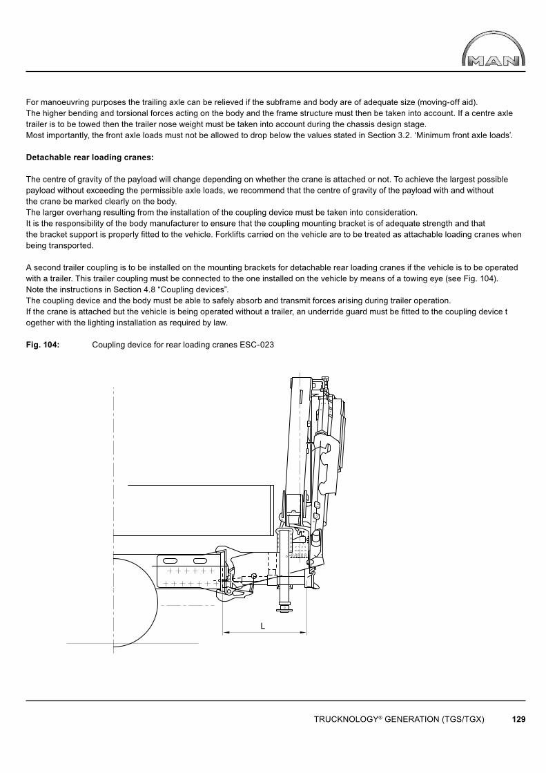
L
TRUCKNOLOGY® GENERATION (TGS/TGX) 129
For manoeuvring purposes the trailing axle can be relieved if the subframe and body are of adequate size (moving-off aid).The higher bending and torsional forces acting on the body and the frame structure must then be taken into account. If a centre axle trailer is to be towed then the trailer nose weight must be taken into account during the chassis design stage.Most importantly, the front axle loads must not be allowed to drop below the values stated in Section 3.2. ‘Minimum front axle loads’.
Detachable rear loading cranes:
The centre of gravity of the payload will change depending on whether the crane is attached or not. To achieve the largest possible payload without exceeding the permissible axle loads, we recommend that the centre of gravity of the payload with and withoutthe crane be marked clearly on the body.The larger overhang resulting from the installation of the coupling device must be taken into consideration.It is the responsibility of the body manufacturer to ensure that the coupling mounting bracket is of adequate strength and thatthe bracket support is properly fitted to the vehicle. Forklifts carried on the vehicle are to be treated as attachable loading cranes when being transported.
A second trailer coupling is to be installed on the mounting brackets for detachable rear loading cranes if the vehicle is to be operated with a trailer. This trailer coupling must be connected to the one installed on the vehicle by means of a towing eye (see Fig. 104).Note the instructions in Section 4.8 “Coupling devices”.The coupling device and the body must be able to safely absorb and transmit forces arising during trailer operation.If the crane is attached but the vehicle is being operated without a trailer, an underride guard must be fitted to the coupling device together with the lighting installation as required by law.
Fig. 104: Coupling device for rear loading cranes ESC-023
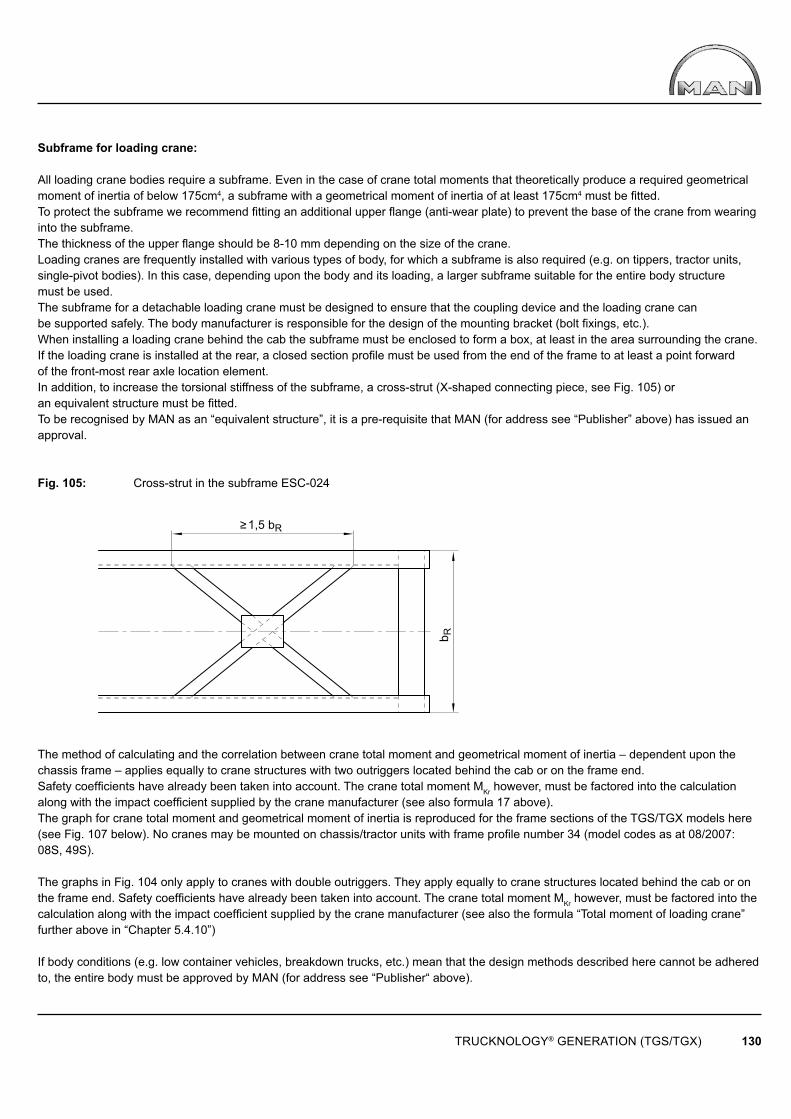
1,5 bR
b R
TRUCKNOLOGY® GENERATION (TGS/TGX) 130
Subframe for loading crane:
All loading crane bodies require a subframe. Even in the case of crane total moments that theoretically produce a required geometrical moment of inertia of below 175cm4, a subframe with a geometrical moment of inertia of at least 175cm4 must be fi tted. To protect the subframe we recommend fi tting an additional upper fl ange (anti-wear plate) to prevent the base of the crane from wearing into the subframe.The thickness of the upper fl ange should be 8-10 mm depending on the size of the crane.Loading cranes are frequently installed with various types of body, for which a subframe is also required (e.g. on tippers, tractor units, single-pivot bodies). In this case, depending upon the body and its loading, a larger subframe suitable for the entire body structure must be used.The subframe for a detachable loading crane must be designed to ensure that the coupling device and the loading crane can be supported safely. The body manufacturer is responsible for the design of the mounting bracket (bolt fi xings, etc.).When installing a loading crane behind the cab the subframe must be enclosed to form a box, at least in the area surrounding the crane.If the loading crane is installed at the rear, a closed section profi le must be used from the end of the frame to at least a point forward of the front-most rear axle location element.In addition, to increase the torsional stiffness of the subframe, a cross-strut (X-shaped connecting piece, see Fig. 105) or an equivalent structure must be fi tted.To be recognised by MAN as an “equivalent structure”, it is a pre-requisite that MAN (for address see “Publisher” above) has issued an approval.
Fig. 105: Cross-strut in the subframe ESC-024
The method of calculating and the correlation between crane total moment and geometrical moment of inertia – dependent upon the chassis frame – applies equally to crane structures with two outriggers located behind the cab or on the frame end. Safety coeffi cients have already been taken into account. The crane total moment MKr however, must be factored into the calculation along with the impact coeffi cient supplied by the crane manufacturer (see also formula 17 above). The graph for crane total moment and geometrical moment of inertia is reproduced for the frame sections of the TGS/TGX models here (see Fig. 107 below). No cranes may be mounted on chassis/tractor units with frame profi le number 34 (model codes as at 08/2007: 08S, 49S).
The graphs in Fig. 104 only apply to cranes with double outriggers. They apply equally to crane structures located behind the cab or on the frame end. Safety coeffi cients have already been taken into account. The crane total moment MKr however, must be factored into the calculation along with the impact coeffi cient supplied by the crane manufacturer (see also the formula “Total moment of loading crane” further above in “Chapter 5.4.10”)
If body conditions (e.g. low container vehicles, breakdown trucks, etc.) mean that the design methods described here cannot be adhered to, the entire body must be approved by MAN (for address see “Publisher“ above).

TRUCKNOLOGY® GENERATION (TGS/TGX) 131
Example of how to use the graphs in Fig. 103:
A subframe is to be specifi ed for a TGS 18.xxx 4x2 BB, model 03S vehicle, frame section number 31. The vehicle is to be fi tted with a crane with a total moment of 160 kNm.
Solution:
A minimum geometrical moment of inertia of approx. 1,250 cm4 is derived from Fig. 107.
If one U-section with a width of 80 mm and a thickness of 8mm is formed into a box with an 8 mm thick section, a section height of at least 170 mm is required, see diagram in Fig. 108. If two U-sections of a width/thickness of 80/8 mm are formed into a box, the minimum height is reduced to approx. 140 mm, see Fig. 109.
If, when the values are read off, the section size in question is not available, round up to the next available size; rounding down is not permitted.
The freedom of movement of all moving parts is not taken into consideration here; it must therefore be re-checked when the dimensions have been selected.
An open U-section, as in Fig. 107, must not be used in the area around the crane. It is only shown here because the diagram can also be used for other bodies.

200
400
600
800
1000
1200
1400
1600
1800
2000
2200
2400
2600
2800
3000
220
200
180
160
140
120
100 80
TRUCKNOLOGY® GENERATION (TGS/TGX) 132
Crane total moment [ kNm ]
Sub
fram
e ge
omet
rical
mom
ent o
f ine
rtia
l x [ c
m4 ]
Pro
fi le
No
31 &
43:
U 2
70/8
5/8
Pro
fi le
No
32 &
45:
U 2
70/8
5/9,
5
Fig. 106: Crane total moment and geometrical moment of inertia for TGS/TGX ESC-516a
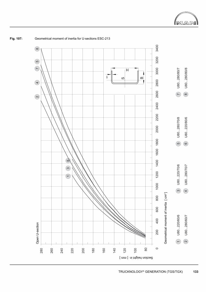
280
260
240
220
200
180
160
140
120
100 80
0 20
0 40
0 60
0 80
0 10
00
1200
14
00
2000
18
00
1600
22
00
2400
26
00
2800
32
00
3000
34
00
1 U
80...
220/
60/6
2 U
80...
280/
60/7
3 U
80...
220/
70/6
4 U
80...
280/
70/7
5 U
80...
280/
70/8
6 U
80...
220/
80/6
7 U
80...
280/
80/7
8 U
80...
280/
80/8
2 4
7 5
8
1 3
H
t
B
S
6
TRUCKNOLOGY® GENERATION (TGS/TGX) 133
Section height in [ mm ]
Geo
met
rical
mom
ent o
f ine
rtia
[ cm
4 ]
Ope
n U
-sec
tion
Fig. 107: Geometrical moment of inertia for U-sections ESC-213

280
260
240
220
200
180
160
140
120
100 80
0
200
400
600
800 1000 1200 1400
2000
1800
1600
2200 2400 2600 2800
3200
3000
3400 3600 3800 4000 4200 4400 4600
1 U
80...
220/
60/6
2 U
80...
280/
60/7
3 U
80...
220/
70/6
4 U
80...
280/
70/7
5 U
80...
280/
70/8
6 U
80...
220/
80/6
7 U
80...
280/
80/7
8 U
80...
280/
80/8
H
t B
t
2 4
7 5
8
1 6
3
TRUCKNOLOGY® GENERATION (TGS/TGX) 134
Section height in [ mm ]
Geo
met
rical
mom
ent o
f ine
rtia
[ cm
4 ]
U-s
ectio
n cl
osed
TGM
TGS
Fig. 108: Geometrical moment of inertia for open U-sections ESC-214
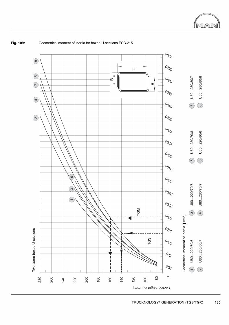
280
260
240
220
200
180
160
140
120
100 80 0
200
600
1000
1400
1800
2200
2600
3000
3400
3800
4200
4600
5000
5400
5800
6200
6600
7000
1U
80...
220/
60/6
2U
80...
280/
60/7
3U
80...
220/
70/6
4U
80...
280/
70/7
5U
80...
280/
70/8
6U
80...
220/
80/6
7U
80...
280/
80/7
8U
80...
280/
80/8
B
H
24
75
8
B
16
3
TRUCKNOLOGY® GENERATION (TGS/TGX) 135
Section height in [ mm ]
Geo
met
rical
mom
ent o
f ine
rtia
[ cm
4 ]
Two
sam
e bo
xed
U-s
ectio
ns
TGM
TGS
Fig. 109: Geometrical moment of inertia for boxed U-sections ESC-215
TRUCKNOLOGY® GENERATION (TGS/TGX) 136
5.4.12 Cable winches
For installation of a cable winch the following points are important:
• Pulling force• Installation location: Front, centre, rear, side installation• Type of drive: Mechanical, electromechanical, electrohydraulic.
Vehicle components such as axles, springs, frames, etc. must under no circumstances be overloaded by the operation of the cable winch. This is particularly important if the direction of the winch towing force is not in line with the vehicle longitudinal axis. It may be necessary to fit an automatic pulling force limiter, a device that cuts-in depending upon the direction from which the pulling force is applied. When a winch is installed at the front, its maximum pulling force is limited by the technically permissible front axle load. The technically permissible front axle load is stated on the vehicle’s manufacturing plate and in the vehicle documentation.A winch design that has pulling forces greater than the technically permissible front axle load may be fi tted only after prior consultation with MAN (for address see „Publisher“ above). Under all circumstances, care must be taken to ensure proper guidance of the cable. The cable should feed through as few guide pulleys as possible. At the same time however, it must be ensured that the function of vehicle parts is in no way adversely affected. A hydraulic winch drive is preferred because it offers better regulation and installation options. The efficiency of the hydraulic pump and motor is to be taken into account (see also the Chapter 9, ‘Calculations’).A check should be made to see whether existing hydraulic pumps such as those on the loading crane or the tipper can be used. This can sometimes avoid the need for installing several power take-offs.The hydraulic circuit on vehicles fitted with HydroDrive ® is a closed circuit system. It may not be tapped to drive a cable winch. On worm gears in mechanical winches, the permissible input speed must be observed (normally < 2,000 rpm).The reduction ratio of the power take-off is to be selected accordingly. Take the low efficiency of the worm gear into consideration when calculating the minimum torque at the power take-off. Observe the instructions contained in the Chapter 6, ‘Electrics, electronics wiring’for electromechanical and electrohydraulic winches.
5.4.13 Transport mixers
The MAN range includes chassis that are suitable for mounting a transport mixer body. These chassis can be recognised by the additional suffix “TM” for Transport Mixer in the sales documentation. The chasis-side requirements and shear plates are included with the vehicle.
In order to reduce the tendency to roll, transport mixer chassis must be fitted with anti-roll bars on both rear axles and must be equipped with springs that are specifi cally tuned for the application.The cement mixer body is generally driven by the fl ywheel-side power take-off (SSNA) at the engine. Further information on power take-offs can be found in the separate ‘Power take-offs’ booklet.If a different chassis (e.g. a tipper chassis) is to be used for mounting a transport mixer it is assumed that the equipment of springs and stabilizers of the axles and shear plate layout equivalent to that of a comparable transport mixer body is fitted and that anti-roll bars for both rear axles are fitted
The shear plate arrangement of tipper chassis and the mounting brackets for loading platforms are not suitable for mounting transport mixer bodies. Fig. 108 illustrates an example for the arrangement of shear plates on a transport mixer chassis.The body is rigid along virtually its entire length, the only exception atng the front end of the subframe ahead of the drum mounting. The first two shear plates must be positioned in the area of the front mounting brackets for the drum. For a more detailed explanation on subframe mountings see section 5.3.4 “Attaching subframes and bodies”. The shear plate thickness should be 8 mm and at least match the material quality S355J2G3 (St52-3).
Concrete conveyor belts and concrete pumps cannot easily be fitted onto standard concrete mixer chassis. In some circumstances, a different subframe structure from that of the normal mixer subframe or a cross connection on the frame end is required (similar to rear loading crane bodies, section 5.4.11, “Subframes for loading cranes”). Approval from MAN (for address see ‘Publisher’ above) and from the transport mixer manufacturer is essential.
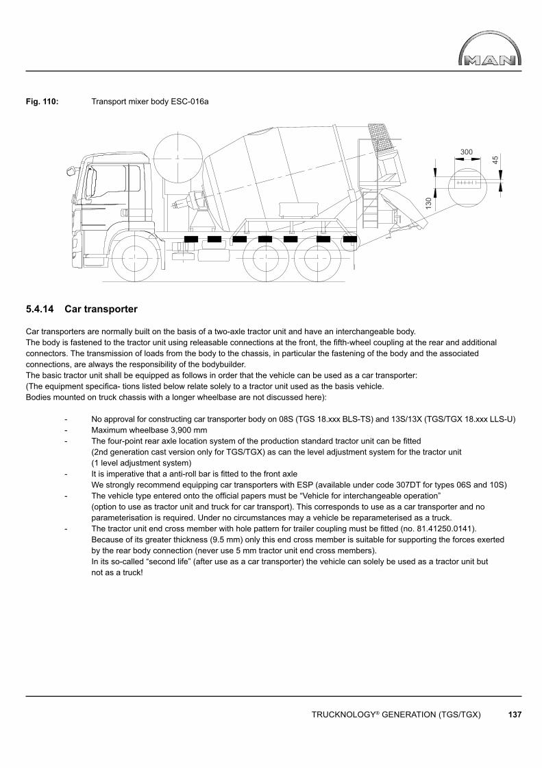
300
130
45
TRUCKNOLOGY® GENERATION (TGS/TGX) 137
Fig. 110: Transport mixer body ESC-016a
5.4.14 Car transporter
Car transporters are normally built on the basis of a two-axle tractor unit and have an interchangeable body. The body is fastened to the tractor unit using releasable connections at the front, the fifth-wheel coupling at the rear and additional connectors. The transmission of loads from the body to the chassis, in particular the fastening of the body and the associated connections, are always the responsibility of the bodybuilder.The basic tractor unit shall be equipped as follows in order that the vehicle can be used as a car transporter: (The equipment specifica- tions listed below relate solely to a tractor unit used as the basis vehicle. Bodies mounted on truck chassis with a longer wheelbase are not discussed here):
- No approval for constructing car transporter body on 08S (TGS 18.xxx BLS-TS) and 13S/13X (TGS/TGX 18.xxx LLS-U) - Maximum wheelbase 3,900 mm - The four-point rear axle location system of the production standard tractor unit can be fitted (2nd generation cast version only for TGS/TGX) as can the level adjustment system for the tractor unit (1 level adjustment system) - It is imperative that a anti-roll bar is fitted to the front axle We strongly recommend equipping car transporters with ESP (available under code 307DT for types 06S and 10S) - The vehicle type entered onto the official papers must be “Vehicle for interchangeable operation” (option to use as tractor unit and truck for car transport). This corresponds to use as a car transporter and no parameterisation is required. Under no circumstances may a vehicle be reparameterised as a truck. - The tractor unit end cross member with hole pattern for trailer coupling must be fitted (no. 81.41250.0141). Because of its greater thickness (9.5 mm) only this end cross member is suitable for supporting the forces exerted by the rear body connection (never use 5 mm tractor unit end cross members). In its so-called “second life” (after use as a car transporter) the vehicle can solely be used as a tractor unit but not as a truck!
TRUCKNOLOGY® GENERATION (TGS/TGX) 138
6. Electrics, electronics, wiring
6.1 General
The Chapter ‘Electrics, electronics, wiring’ does not attempt to provide fully comprehensive information on all issues relating to the vehicle electrical systems of modern commercial vehicles. Further information on individual systems can be found in the respective repair manuals, which can be obtained from the spare parts service. The electrics, electronics and wiring installed in commercial vehicles complies with the relevant applicable national and European standards and directives, which are to be regarded as minimum requirements. MAN’s own standards often considerably exceed those minimum requirements of national and international standards. As a result, many electronic systems have been adapted and expanded. In some situations, for reasons of quality or safety, MAN stipulates the condition that MAN standards are used. This is stated in the corresponding sections. Body manufacturers can obtain relevant MAN standards from www.normen.man-nutzfahrzeuge.de (registration required). There is no automatic updating and replacement service.
6.2 Routing cables, earth cable
On MAN vehicles the frame is not misused as the earth cable; instead, a separate earth cable should be laid to the electric consumer along with the positive lead. Common earth points to which the bodybuilder can connect earth cables are located:
• In the central electrics compartment (rear, see fi g. 111)• Behind the instrumentation• On the rear right-hand engine mount.
For detailed instructions see section 6.5 additional power consumers, below.No more than 10A (actual current consumption) in total may be drawn at the earth points behind the central electrics box and behind the instrumentation. Cigarette lighters and any additional sockets have their own power limits, please refer to the respective instruction manual. The body builder’s negative cable may as a general rule be connected to the common earth points at the engine and under the following conditions may be connected to the negative terminal of the batteries:
• The vehicle is equipped with an earth cable between engine and frame (standard from January 2010 production).• The battery terminal has suffi cient room for connection of the earth cable.
6.3 Handling batteries
6.3.1 Handling and maintaining batteries
The test and charging cycle in accordance with the charging log/ charging schedule applies (e.g. when the vehicle is not being used whilst the body is being fitted). Checking/charging the battery is to be carried out according to the charging log supplied with the vehicle and is to be initialled.
Rapid charging or assist-starting equipment is not permitted for trickle charging since their use may damage control units.Vehicle to vehicle assist-starting is permitted, provided the instructions in the operating manual are followed. When the engine is running:
• Do not switch off the battery main switch• Do not loosen or disconnect the battery terminals.

TRUCKNOLOGY® GENERATION (TGS/TGX) 139
Caution!
Always follow this sequence when disconnecting the batteries and actuating the battery main switch:
• Switch off all electric consumers (e.g. lights, hazard warning lights)• Switch off ignition• Close the doors• Wait for a period of 20 seconds before disconnecting the batteries (negative terminal first)• The electric battery main switch requires an additional run-down time of 15 seconds.
Reason:
Many vehicle functions are controlled by the central on-board computer (ZBR) that must first save its last status before it can be isolated.If, for example, the doors remain open, it will be 5 minutes before the computer can stop operating, because the computer also monitorsthe door-closing function. If the doors are open a waiting period of over 5 minutes is therefore necessary before the batteries can be disconnected. Closing the doors will shorten this waiting time to 20 seconds.If the above sequence is not followed some control units will inevitably have incorrect entries (e.g. the ZBR central on-board computer).
6.3.2 Handling and maintaining batteries with PAG technology
When original factory-fi tted batteries are exhausted MAN specialist workshops will only fi t maintenance free PAG technology batteries (PAG = positive Ag, positive electrode with thin silver plating). These differ from conventional batteries through improved resistance to deep-discharge damage, longer shelf-life and better charging rate. The conventional fi ller caps have been replaced by „charge eyes“. The test and charging cycle in accordance with the charging log/charging schedule is monitored with the help of these charge eyes which indicate the state of charge by the colour of the ball in the middle of the fi ller cap.
Caution!
The fi ller caps (charge eyes) of maintenance-free batteries must not be opened.
Table 29: Charge eye indications
Indication Battery condition ProcedureGreen Correct electrolyte level, acid density above 1.21 g/cm3 The battery is charged and in order.
Note check completed in the charging log Black Correct electrolyte level, but acid density below 1.21 g/cm3 The battery must be charged.
Note the recharge in the charging logWhite Electrolyte level too low, acid density may lie above or below 1.21 g/cm3 The battery must be replaced
A detailed Service Information, „SI Number: Amendment 2, 114002 Battery“ is available from MAN specialist workshops.
TRUCKNOLOGY® GENERATION (TGS/TGX) 140
6.4 Additional wiring diagrams and wiring harness drawings
Additional wiring diagrams and wiring harness drawings that contain or describe body fittings can be obtained from MAN (for address see ‘Publisher’ above). It is the responsibility of body manufacturer to ensure that the documents he uses,for example wiring diagrams and wiring harness drawings, correspond with the current status of equipment fitted to the vehicle. Further technical information can be obtained from the repair manuals. These can be obtained from the spare parts service.
6.5 Fuses, additional power consumers
Do not modify or extend the vehicle’s electrical system! This applies to the central electrics box in particular.Any damage resulting from modifications will be the responsibility of those who carried out the modifications.
The following points must be observed when retrofitting additional electric consumers:
There are no spare fuses in the central electrics box for use by the body manufacturer. Additional fuses can be fitted in a plastic holder located in front of the central electrics box.Do not tap into existing vehicle circuits or connect additional electric consumers to fuses that are already occupied.Each circuit installed by the body manufacturer must be adequately rated and have its own fuses. The rating of the fuse should ensurethe protection of the wiring and not that of the system connected to it. Electrical systems must ensure adequate protection against all possible faults, without affecting the vehicle electrics. Freedom from feedback must always be ensured.
When selecting the size of the wire cross-section, the voltage drop and the heating of the conductor must be taken into account.Cross-sections below 1 mm2 are to be avoided because their mechanical strength is not sufficient. Positive and negative wires must have the same minimum cross-section.Current draw for 12V equipment must be effected only via a voltage converter. Power draw from just one battery is not permitted because unequal charge statuses may cause the other battery to become overcharged and damaged.Under certain circumstances, e.g. for equipment with a high power requirement (e.g. electrohydraulic tail-lifts) or in extreme climatic conditions, higher capacity batteries will be required. In order to provide extra power, a larger capacity alternator is available ex-works. If the body manufacturer installs larger batteries, the cross-section of the battery cable must be adapted to suit the new power draw.If consumers are directly connected to terminal 15 (pin 94 in the central electrics box; see Fig. 111) it is possible that entries will be logged in the error memories of control units as a result of a reverse fl ow of current into the vehicle‘s electrical system. Consumers must therefore, be connected in accordance with the following instructions.
Power supply terminal 15Always fi t a relay that is triggered via terminal 15 (pin 94). The load must be connected through a circuit breaker at terminal 30 (pins 90-1, 90-2 and 91 at the rear of the central electrics box) (see Fig. 111). The maximum load must not exceed 10 amperes
Power supply terminal 30• For maximum loads of up to 10 amperes the load must be connected through a circuit breaker at terminal 30 (pins 90-1, 90-2 and 91, see Fig. 111 rear of the central electrics box).• For loads > 10 amperes connect through a circuit breaker directly at the batteries
Power supply terminal 31• Do not connect at the batteries, instead connect to the earth points inside (see Fig. 111 rear of the central electrics box) and outside (rear left engine mounting) the cab.
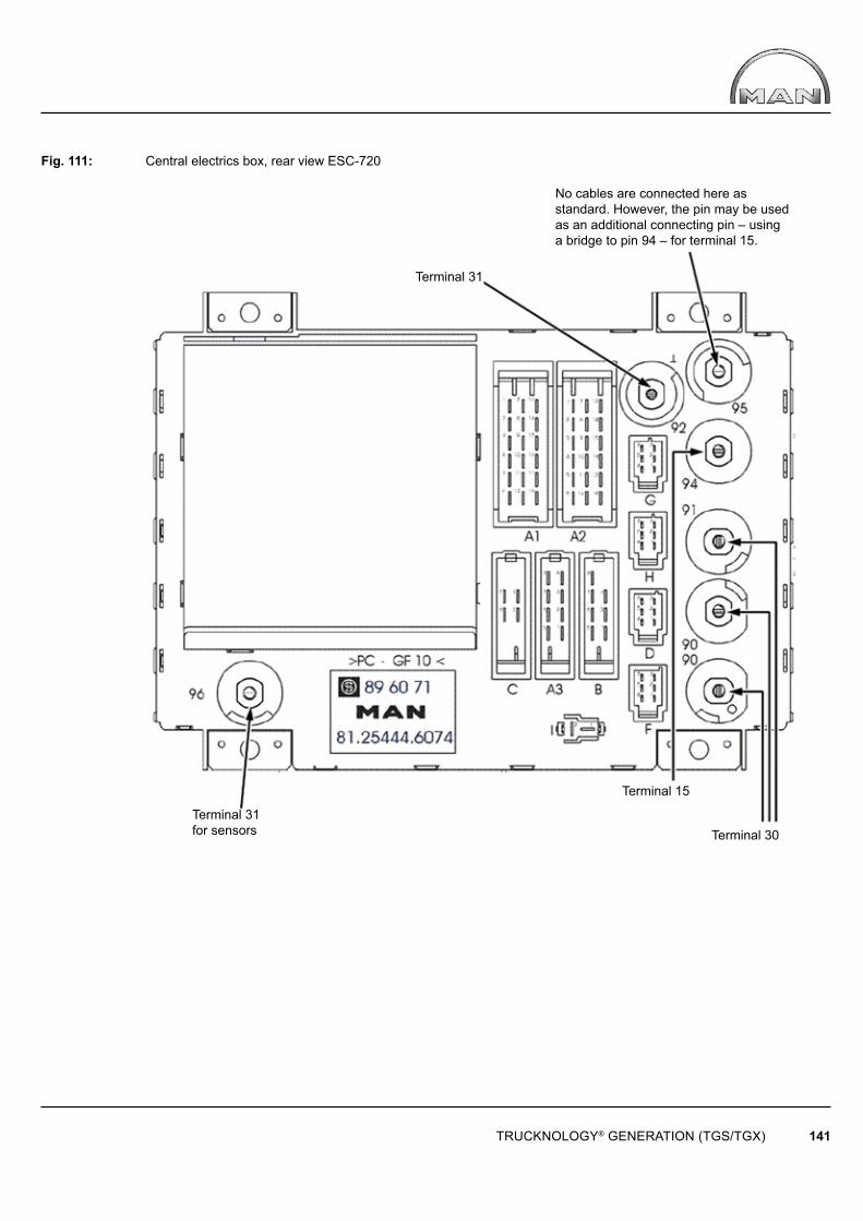
TRUCKNOLOGY® GENERATION (TGS/TGX) 141
Terminal 31
Terminal 30
Terminal 15
Terminal 31for sensors
No cables are connected here as standard. However, the pin may be used as an additional connecting pin – using a bridge to pin 94 – for terminal 15.
Fig. 111: Central electrics box, rear view ESC-720
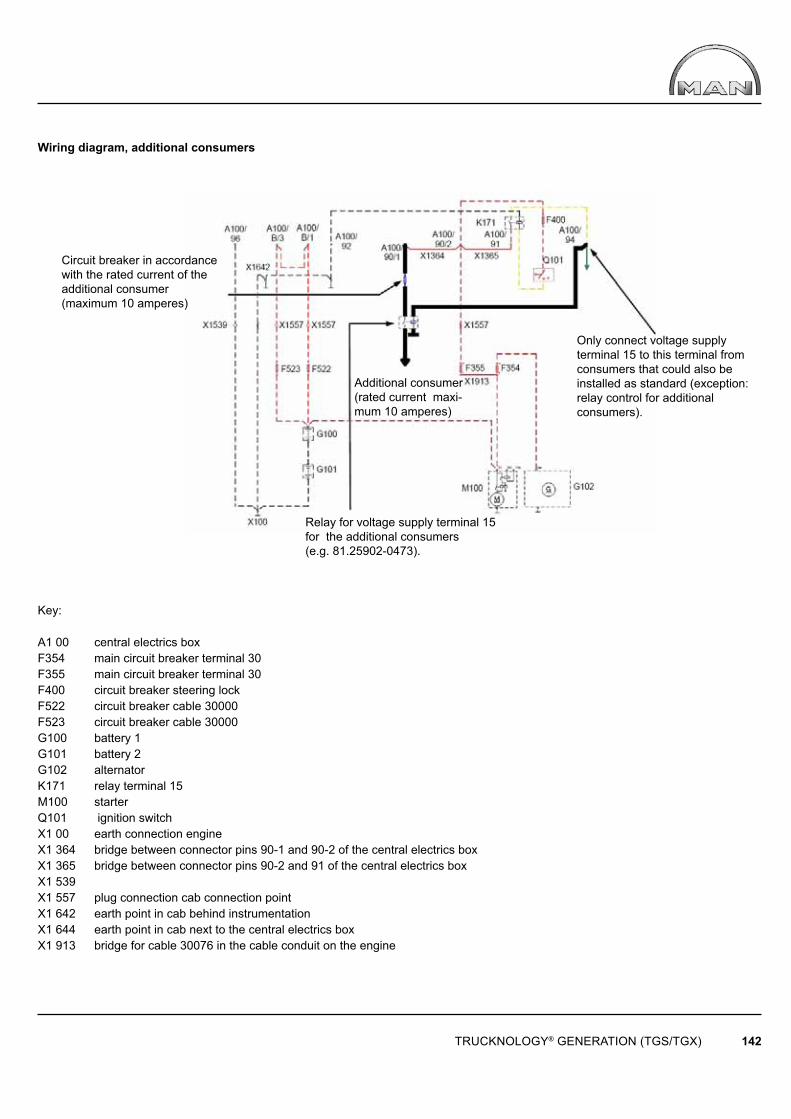
TRUCKNOLOGY® GENERATION (TGS/TGX) 142
Circuit breaker in accordance with the rated current of the additional consumer (maximum 10 amperes)
Additional consumer (rated current maxi-mum 10 amperes)
Relay for voltage supply terminal 15 for the additional consumers (e.g. 81.25902-0473).
Only connect voltage supply terminal 15 to this terminal from consumers that could also be installed as standard (exception: relay control for additional consumers).
Wiring diagram, additional consumers
Key:
A1 00 central electrics boxF354 main circuit breaker terminal 30F355 main circuit breaker terminal 30F400 circuit breaker steering lockF522 circuit breaker cable 30000F523 circuit breaker cable 30000G100 battery 1G101 battery 2G102 alternatorK171 relay terminal 15M100 starterQ101 ignition switchX1 00 earth connection engineX1 364 bridge between connector pins 90-1 and 90-2 of the central electrics boxX1 365 bridge between connector pins 90-2 and 91 of the central electrics boxX1 539 X1 557 plug connection cab connection pointX1 642 earth point in cab behind instrumentationX1 644 earth point in cab next to the central electrics boxX1 913 bridge for cable 30076 in the cable conduit on the engine
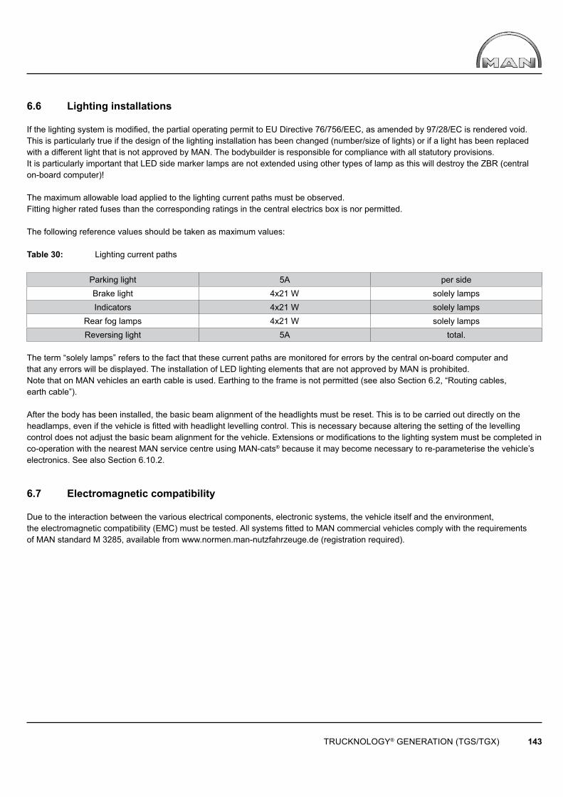
TRUCKNOLOGY® GENERATION (TGS/TGX) 143
6.6 Lighting installations
If the lighting system is modified, the partial operating permit to EU Directive 76/756/EEC, as amended by 97/28/EC is rendered void. This is particularly true if the design of the lighting installation has been changed (number/size of lights) or if a light has been replaced with a different light that is not approved by MAN. The bodybuilder is responsible for compliance with all statutory provisions.It is particularly important that LED side marker lamps are not extended using other types of lamp as this will destroy the ZBR (central on-board computer)!
The maximum allowable load applied to the lighting current paths must be observed.Fitting higher rated fuses than the corresponding ratings in the central electrics box is nor permitted.
The following reference values should be taken as maximum values:
Table 30: Lighting current paths
Parking light 5A per sideBrake light 4x21 W solely lampsIndicators 4x21 W solely lamps
Rear fog lamps 4x21 W solely lampsReversing light 5A total.
The term “solely lamps” refers to the fact that these current paths are monitored for errors by the central on-board computer andthat any errors will be displayed. The installation of LED lighting elements that are not approved by MAN is prohibited.Note that on MAN vehicles an earth cable is used. Earthing to the frame is not permitted (see also Section 6.2, “Routing cables, earth cable”).
After the body has been installed, the basic beam alignment of the headlights must be reset. This is to be carried out directly on the headlamps, even if the vehicle is fitted with headlight levelling control. This is necessary because altering the setting of the levellingcontrol does not adjust the basic beam alignment for the vehicle. Extensions or modifications to the lighting system must be completed inco-operation with the nearest MAN service centre using MAN-cats® because it may become necessary to re-parameterise the vehicle’s electronics. See also Section 6.10.2.
6.7 Electromagnetic compatibility
Due to the interaction between the various electrical components, electronic systems, the vehicle itself and the environment, the electromagnetic compatibility (EMC) must be tested. All systems fi tted to MAN commercial vehicles comply with the requirements of MAN standard M 3285, available from www.normen.man-nutzfahrzeuge.de (registration required).
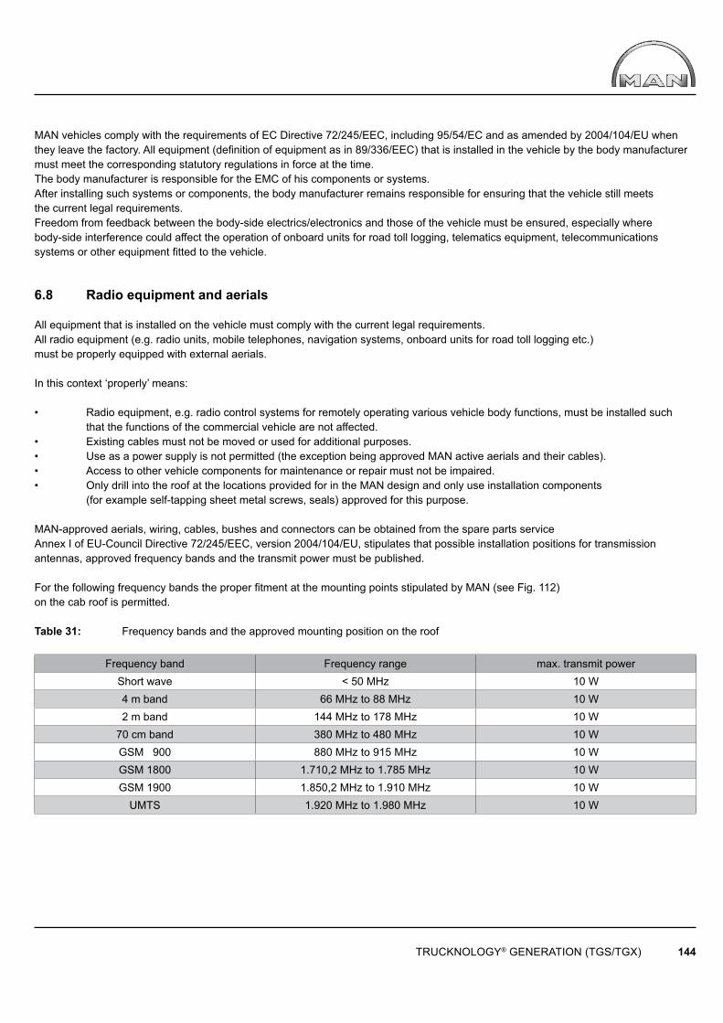
TRUCKNOLOGY® GENERATION (TGS/TGX) 144
MAN vehicles comply with the requirements of EC Directive 72/245/EEC, including 95/54/EC and as amended by 2004/104/EU when they leave the factory. All equipment (defi nition of equipment as in 89/336/EEC) that is installed in the vehicle by the body manufacturer must meet the corresponding statutory regulations in force at the time. The body manufacturer is responsible for the EMC of his components or systems.After installing such systems or components, the body manufacturer remains responsible for ensuring that the vehicle still meets the current legal requirements.Freedom from feedback between the body-side electrics/electronics and those of the vehicle must be ensured, especially where body-side interference could affect the operation of onboard units for road toll logging, telematics equipment, telecommunications systems or other equipment fi tted to the vehicle.
6.8 Radio equipment and aerials
All equipment that is installed on the vehicle must comply with the current legal requirements. All radio equipment (e.g. radio units, mobile telephones, navigation systems, onboard units for road toll logging etc.) must be properly equipped with external aerials. In this context ‘properly’ means:
• Radio equipment, e.g. radio control systems for remotely operating various vehicle body functions, must be installed such that the functions of the commercial vehicle are not affected.• Existing cables must not be moved or used for additional purposes.• Use as a power supply is not permitted (the exception being approved MAN active aerials and their cables).• Access to other vehicle components for maintenance or repair must not be impaired.• Only drill into the roof at the locations provided for in the MAN design and only use installation components (for example self-tapping sheet metal screws, seals) approved for this purpose.
MAN-approved aerials, wiring, cables, bushes and connectors can be obtained from the spare parts serviceAnnex I of EU-Council Directive 72/245/EEC, version 2004/104/EU, stipulates that possible installation positions for transmission antennas, approved frequency bands and the transmit power must be published.
For the following frequency bands the proper fi tment at the mounting points stipulated by MAN (see Fig. 112) on the cab roof is permitted.
Table 31: Frequency bands and the approved mounting position on the roof
Frequency band Frequency range max. transmit powerShort wave < 50 MHz 10 W4 m band 66 MHz to 88 MHz 10 W2 m band 144 MHz to 178 MHz 10 W
70 cm band 380 MHz to 480 MHz 10 WGSM 900 880 MHz to 915 MHz 10 W GSM 1800 1.710,2 MHz to 1.785 MHz 10 WGSM 1900 1.850,2 MHz to 1.910 MHz 10 W
UMTS 1.920 MHz to 1.980 MHz 10 W
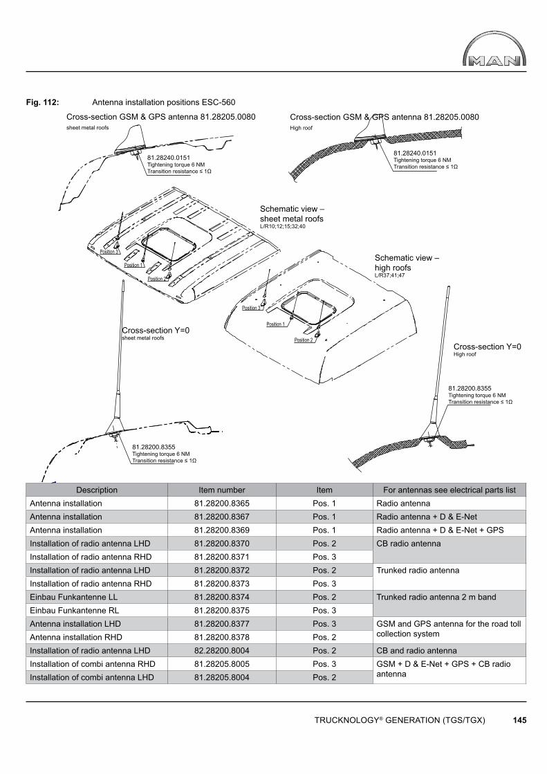
Position 2
Position 1
Position 3
Position 2
Position 1
Position 3
TRUCKNOLOGY® GENERATION (TGS/TGX) 145
Description Item number Item For antennas see electrical parts listAntenna installation 81.28200.8365 Pos. 1 Radio antennaAntenna installation 81.28200.8367 Pos. 1 Radio antenna + D & E-NetAntenna installation 81.28200.8369 Pos. 1 Radio antenna + D & E-Net + GPSInstallation of radio antenna LHD 81.28200.8370 Pos. 2 CB radio antennaInstallation of radio antenna RHD 81.28200.8371 Pos. 3Installation of radio antenna LHD 81.28200.8372 Pos. 2 Trunked radio antennaInstallation of radio antenna RHD 81.28200.8373 Pos. 3Einbau Funkantenne LL 81.28200.8374 Pos. 2 Trunked radio antenna 2 m bandEinbau Funkantenne RL 81.28200.8375 Pos. 3Antenna installation LHD 81.28200.8377 Pos. 3 GSM and GPS antenna for the road toll
collection systemAntenna installation RHD 81.28200.8378 Pos. 2Installation of radio antenna LHD 82.28200.8004 Pos. 2 CB and radio antennaInstallation of combi antenna RHD 81.28205.8005 Pos. 3 GSM + D & E-Net + GPS + CB radio
antennaInstallation of combi antenna LHD 81.28205.8004 Pos. 2
81.28240.0151Tightening torque 6 NMTransition resistance ≤ 1Ω
81.28240.0151Tightening torque 6 NMTransition resistance ≤ 1Ω
Cross-section GSM & GPS antenna 81.28205.0080High roof
Cross-section GSM & GPS antenna 81.28205.0080sheet metal roofs
Schematic view – sheet metal roofsL/R10;12;15;32;40
Schematic view – high roofsL/R37;41;47
Cross-section Y=0High roof
81.28200.8355Tightening torque 6 NMTransition resistance ≤ 1Ω
81.28200.8355Tightening torque 6 NMTransition resistance ≤ 1Ω
Cross-section Y=0sheet metal roofs
Fig. 112: Antenna installation positions ESC-560
TRUCKNOLOGY® GENERATION (TGS/TGX) 146
6.9 Interfaces on the vehicle, preparations for the body
No work is permitted on the vehicle’s electrical system other than via the interfaces provided by MAN (e.g. for tail-lifts, for start/stop equipment, for intermediate speed regulation, FMS interface). Tapping into the CAN buses is prohibited except in the case ofthe Body builder CAN bus – see the control unit TG interface for external data exchange (KSM). The interfaces are described in detail in the ‘Interfaces TG’ booklet.
If the vehicle is ordered with body fittings (e.g. start/stop device on the end of the frame), these are already fitted at the factory and partly connected. The instrumentation is prepared in accordance with the order.Before first operation of the body fittings, the body manufacturer must ensure that valid, up-to-date versions of wiring diagrams and wiring harness drawings are in use (see also Section 6.4).Transport securing devices are fitted by MAN (on the interfaces behind the front panel on the passenger side) for delivery of the vehicleto the body manufacturer.Before using each interface the transport securing devices must be properly removed.The retrofitting of interfaces and/or body fittings is often extremely complicated. It should not be attempted without enlisting the help of an electronics specialist from the MAN service organisation.
Connecting to the D+ signal (engine running)Caution: D+ may not be tapped from the alternator on TG vehicles.
In addition to the signals and information provided through the KSM interface it is also possible to tap into the D+ signal as follows: The central on-board computer (ZBR) provides an “Engine running” signal (+24V).This can be tapped into directly at the ZBR (socket F2 pin 17).The maximum load on this connection may not exceed 1 Ampere. It should be noted that other internal consumers may alsobe connected here. It must be ensured that this connection is free from feedback.
Remote transmission of data from the mass storage of digital tachographs and information contained on the driver card.MAN supports the manufacturer-independent remote transmission of data from the mass storage of digital tachographs and information contained on the driver card (RDL = remote download).

TRUCKNOLOGY® GENERATION (TGS/TGX) 147
6.9.1 Electrical connections for tail-lifts
See Chapter ‚Tail-lifts‘
6.9.2 Engine start-stop system
The „engine start-stop system“ allows the vehicle engine to be started or stopped via a remote control or switch outside the cab. The start-stop control is a system that works independently of the intermediate speed control interface and must be ordered separately.
There are various options available ex-works:
• Engine start-stop system under the front panel (preparation)• Engine start-stop system on the engine• Engine start-stop system at the end of the frame (preparation)
If a variant does not exist or is not available as optional equipment for a vehicle, the “engine start-stop system” can be retrofi tted. It must then be ensured that both the original MAN wiring harnesses and the documented connection options and locations are used.
It is also possible to incorporate the “engine start-stop system” via the CAN data bus. The requirement for this is that the customer-specifi c control module (KSM) is installed in the vehicle at the factory. Further references, connection and signal descriptions can be found in the separate guideline, “TG Interfaces”.
Specifi c parameterisation is not necessary for the “engine start-stop system”.
If the body manufacturer has installed the circuitry, the designation engine start-stop must be used. This must not be confused with the term emergency stop.
6.9.3 Tapping into the speed signal
Caution! In order to avoid control unit error messages always switch off the ignition prior to carrying out any work on the tachograph!It is possible to tap the speed signal from the tachograph. This will ensure that the load on the corresponding pin does not exceed 1 mA! This is generally equates to the equivalent of two connected peripheral units. Should this option for tapping the signal be inadequate then the following output multipliers bearing the MAN codes can be connected:81.25311-0022 (3 * v-pulse output, max. load 1 mA for each output) or88.27120-0003 (5 * v-pulse output, max. load 1 mA for each output).
Option for tapping the ‘B7 signal’ = speed signal:1) At connector B / Pin 7 or PIN 6 on the back of the tachograph2) At the 3-pole plug connection X4366 / contact 1. The plug connection is located behind a cover on the driver side A-pillar in the area around the driver’s footwell.3) At the 2-pole plug connection X4659 / contact 1 or 2. The plug connection is located behind the central electrical compartment4) At the factory-fitted interface with customer-specifi c control module from STEP1 (see the booklet “TG electrical and electronic interfaces”, Chapter 4.3).
6.9.4 Tapping into the reverse gear signal
There are several options for tapping the reverse gear signal on vehicles in the TGS/TGX range. The reverse gear signal can be tapped via the 2-pin connector X1627 at pin 1 or pin 2 of cable 71300. This is located in the central electrical compartment. It must be ensured that the electrical load on the interface for the reverse gear signal does not exceed a permissible value of 100mA.
It is also possible to tap the reverse gear signal via the customer-specifi c module (KSM). The requirement for this is that a customer-specifi c module (KSM) was fi tted at the factory. Further information, connection and signal descriptions can be found in the separate Guide to Fitting Bodies booklet “TG Interfaces”.
Caution! All work must be carried out with the ignition turned off or with the battery disconnected. In addition to the accident prevention regulations the applicable country-specifi c guidelines and laws must also be observed.
TRUCKNOLOGY® GENERATION (TGS/TGX) 148
6.10 Electronics
The TGS/TGX range employs many electronic systems for controlling, regulating and monitoring vehicle functions. The electronic braking system (EBS), electronic air suspension (ECAS) and the electronic diesel injection system (EDC) are just a few examples. Full networking of the equipment fully guarantees that sensor readings can be processed to the same extent by all control units.This enables the number of sensors, cables and connections to be reduced, which in turn reduces the number of possible fault-sources. On the vehicle, network cables can be recognised because they are twisted. Several CAN bus systems are used in parallel and this enables them to be optimally adapted to perform their respective tasks.All data bus systems are reserved for exclusive use by the MAN vehicle electronics system; access to these bus systems is prohibited except in the case of the Body builder CAN bus – see the control unit TG interface for external data exchange (KSM).
6.10.1 Display and instrumentation concept
The instrument cluster installed in the TGS/TGX is incorporated into the control unit network by means of a CAN bus system. Faults are displayed in plain text directly in the central display or through error codes. The instrumentation receives all the information that is displayed in the form of a CAN message. Long-life LEDs are used instead of bulbs. The annunciator panel is vehicle-specifi c, i.e. only functions and fi ttings that have been ordered are present. If other functions are retrofi tted at a later date and these are to be displayed (e.g. retrofi tted tail-lift, seatbelt tensioner, tipper display in the cab) the system has to be re-parameterised using MAN-cats®. An annunciator panel that matches the new parameters can be ordered from the MAN spare parts service.In this way, body manufacturers may elect to have the superstructure functions, e.g. tail-lift or tipper operation, parameterised on the vehicle and the instrumentation, together with the required symbols on the annunciator panel, installed during manufacture. It is neither possible to incorporate superstructure functions on an „in reserve“ basis nor is it permitted for the body manufacturer to incorporate his own functions into the central display or tap signals from the back of the instrumentation.
6.10.2 Diagnostics concept and parameterisation using MAN-cats®
MAN-cats® is the second generation MAN tool for diagnosis and parameterisation of electronic vehicle systems. MAN-cats® is therefore used by all MAN service centres. If the body manufacturer or the customer informs MAN of the intended use or the body type (e.g. for the intermediate speed control interface) when the vehicle is ordered, these can be incorporated into the vehicle at the factory using EOL programming (EOL = end of line). MAN-cats® must be used if these parameters are to be changed. For certain types of intervention in the vehicle systems the electronics specialists at MAN service centres are able to contact systems specialists at the MAN factory to obtain the appropriate clearances, approvals and system solutions.
6.10.3 Parameterisation of the vehicle electronics
If any modifi cations that require approval or that are critical to safety are carried out on the vehicle, or if the chassis needs to be modifi ed to adapt it to the body, or if conversion work or retrofi tting work needs to be carried out, a MAN-cats® specialist at the nearest MAN service station must be consulted before any work commences to see if the vehicle needs to be re-parameterised.
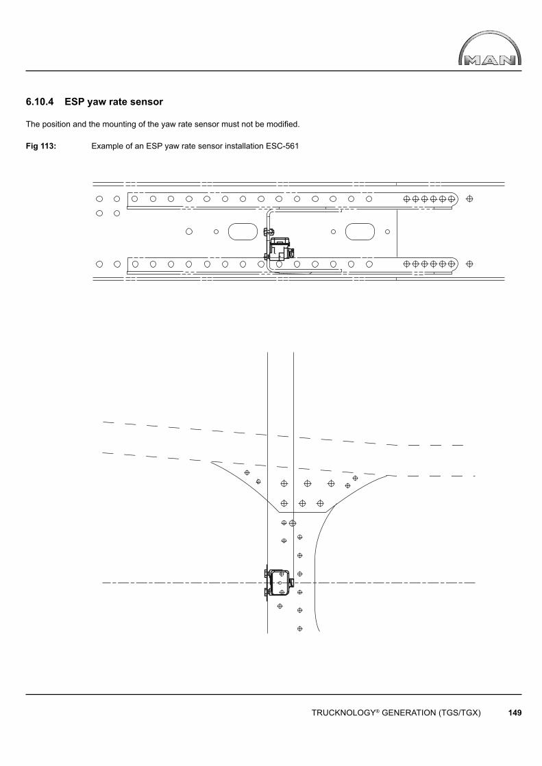
TRUCKNOLOGY® GENERATION (TGS/TGX) 149
6.10.4 ESP yaw rate sensor
The position and the mounting of the yaw rate sensor must not be modifi ed.
Fig 113: Example of an ESP yaw rate sensor installation ESC-561

TRUCKNOLOGY® GENERATION (TGS/TGX) 150
A
6.10.5 Emergency Brake Assist
The Emergency Brake Assist system (EBA) is a driver/brake assist system. It warns the driver of a potential rear-end collision accident and initiates action when it detects an emergency situation. If necessary, the EBA will automatically apply the vehicle’s brakes in order to minimise the effects of a collision or avoid an accident entirely. The EBA receives information about road and traffi c conditions in front of the vehicle from a radar sensor mounted within the front bumper (see fi gure 114 detail A).
Fig. 114: Front of cab showing the installed position of the radar sensor using an Effi cientLine vehicle as an example ESC-565
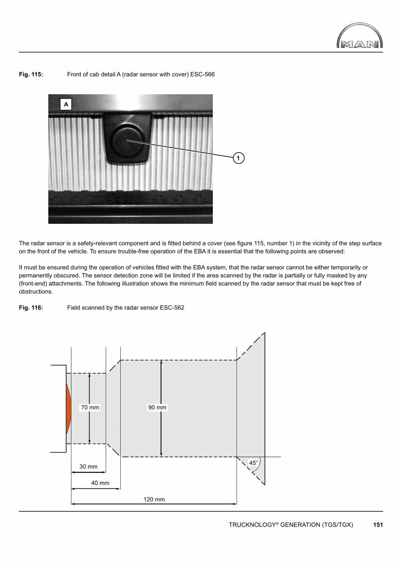
30 mm
40 mm
120 mm
70 mm 90 mm
45°
TRUCKNOLOGY® GENERATION (TGS/TGX) 151
1
A
Fig. 115: Front of cab detail A (radar sensor with cover) ESC-566
The radar sensor is a safety-relevant component and is fi tted behind a cover (see fi gure 115, number 1) in the vicinity of the step surface on the front of the vehicle. To ensure trouble-free operation of the EBA it is essential that the following points are observed:
It must be ensured during the operation of vehicles fi tted with the EBA system, that the radar sensor cannot be either temporarily or permanently obscured. The sensor detection zone will be limited if the area scanned by the radar is partially or fully masked by any (front-end) attachments. The following illustration shows the minimum fi eld scanned by the radar sensor that must be kept free of obstructions.
Fig. 116: Field scanned by the radar sensor ESC-562
TRUCKNOLOGY® GENERATION (TGS/TGX) 152
Caution: On vehicles where the fi eld scanned by the radar sensor is either temporarily or permanently obscured by attachments or other components (e.g. snowplough blade, cable winch attachment, other covers or any type of plate etc.), the EBA and ACC functions must be permanently deactivated using a conversion data fi le.During operation, fl exible components on the vehicle or attachments (electric cables, hoses, wire cables or similar) must also be prevented from entering the fi eld scanned by the radar sensor.
For trouble-free operation of the EBA the following points must also be observed:
• The position of the radar sensor determined at the factory, its cover and attachment bracket may not be altered.• Neither the position nor the location, material or surface characteristics (using adhesives, grinding, painting etc.) may be modifi ed.• The bracket – including the attachment point for the radar sensor – may not be loosened or modifi ed.• Attaching other components or cables/hoses to the sensor bracket is not permitted.• Modifi cations to or interventions in the wiring harness are not permitted.
If loosening the attachment bracket or removing the radar sensor cannot be avoided due to maintenance or repair work, the following guidelines must also be observed for re-installation:
• The radar sensor together with its bracket and cover must be re-attached in the position determined by the factory.• Only original MAN parts may be used for attachment purposes or as spares.• The sensor must be calibrated by a MAN Service Centre.
The EBA warns the driver with (among others) an acoustic signal, as soon as it detects a risk of collision. To ensure that this acoustic signal will always operate properly, the original MAN loudspeakers (dual coil speakers) must be left in-place.As soon as the Emergency Brake Assist system applies the vehicle’s brakes the brake lights are activated to warn following traffi c. Changing the brake lights fi tted at the factory or replacing them with rear light units that are not approved by MAN is therefore not permitted. Further information about the lighting installation can be found in section 6.6 “Lighting installation”.
Following modifi cations to the rear axle/rear axles, to the main frame of the vehicle or changes of tyre type and the installation of additional axles, the sensor must be calibrated by correspondingly trained personnel/an MAN Service Centre. Once the modifi cation work has been completed the parameterisation of the vehicle’s electronics must be checked and adjusted where required.
TRUCKNOLOGY® GENERATION (TGS/TGX) 153
7. Power take-off → See separate booklet
8. Brakes, lines
The braking system is among the most important safety components on a truck. No changes should be made to any part of the brake system including the brake lines except by suitably trained personnel. After any change a complete visual, audible, function and effi ciency test of the complete braking system is to be performed.
8.1 ALB, EBS braking system
Due to the EBS it is not necessary for the body manufacturer to check the ALB (automatic load-dependent brake system); it is in any case not possible to make adjustments. A check may possibly be required in line with the scheduled inspection of the braking system(in Germany SP and section 29 StVZO). Should such an inspection of the braking system become necessary then a voltagemeasurement using the MAN-cats diagnosis system or a visual check of the angle of the linkage at the axle load sensor must be carried out. The EBS of vehicles fi tted with air suspension uses the axle load signal transmitted by the ECAS via the CAN data bus. If conversions are carried out it must be ensured that this axle load information is not affected.Never pull-out the plug on the axle load sensor. Before exchanging leaf springs, e.g. replacing them with springs for a different load,it should be checked with the MAN workshop whether reparameterisation of the vehicle is necessary in order to be able to set the ALBcorrectly.
8.2 Brake and compressed air lines
8.2.1 Basic principles
• Polyamide (PA) tubes must in all circumstances: - be kept away from heat sources - be laid in such a way that no abrasion can occur - be free from trapped stresses - be laid without kinking.• Only PA tubing in accordance with DIN 74324 part 1 or to MAN standard M 3230 Part 1 is to be used (www.normen.man-nutzfahrzeuge.de, registration required). In accordance with the standard this tubing is marked with a number starting with ‘M 3230’ or ISO7628’ ‘every 350 mm.• Remove lines to protect them before welding work takes place. • For welding work, see also the Chapter „Modifying the chassis“ – „Welding the frame“ section.• In view of the risk of heat build-up, PA pipes must not be attached to metal pipes or holders that are connected to the following assemblies: - Engine - Air compressor - Heating - Radiator - Hydraulic system.
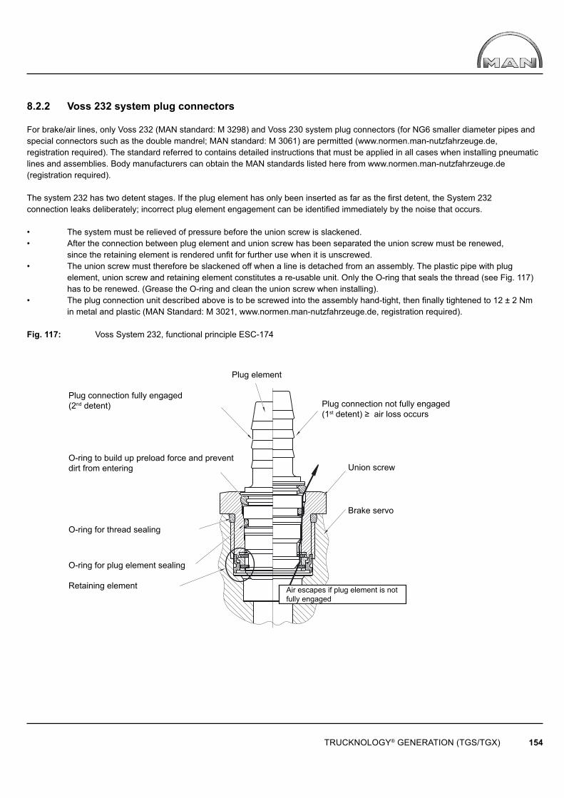
TRUCKNOLOGY® GENERATION (TGS/TGX) 154
Plug element
Air escapes if plug element is not fully engaged
Plug connection fully engaged(2nd detent)
O-ring to build up preload force and prevent dirt from entering
O-ring for thread sealing
O-ring for plug element sealing
Retaining element
Plug connection not fully engaged(1st detent) ≥ air loss occurs
Union screw
Brake servo
8.2.2 Voss 232 system plug connectors
For brake/air lines, only Voss 232 (MAN standard: M 3298) and Voss 230 system plug connectors (for NG6 smaller diameter pipes and special connectors such as the double mandrel; MAN standard: M 3061) are permitted (www.normen.man-nutzfahrzeuge.de, registration required). The standard referred to contains detailed instructions that must be applied in all cases when installing pneumatic lines and assemblies. Body manufacturers can obtain the MAN standards listed here from www.normen.man-nutzfahrzeuge.de (registration required).
The system 232 has two detent stages. If the plug element has only been inserted as far as the fi rst detent, the System 232connection leaks deliberately; incorrect plug element engagement can be identifi ed immediately by the noise that occurs.
• The system must be relieved of pressure before the union screw is slackened.• After the connection between plug element and union screw has been separated the union screw must be renewed, since the retaining element is rendered unfi t for further use when it is unscrewed.• The union screw must therefore be slackened off when a line is detached from an assembly. The plastic pipe with plug element, union screw and retaining element constitutes a re-usable unit. Only the O-ring that seals the thread (see Fig. 117) has to be renewed. (Grease the O-ring and clean the union screw when installing).• The plug connection unit described above is to be screwed into the assembly hand-tight, then fi nally tightened to 12 ± 2 Nm in metal and plastic (MAN Standard: M 3021, www.normen.man-nutzfahrzeuge.de, registration required).
Fig. 117: Voss System 232, functional principle ESC-174
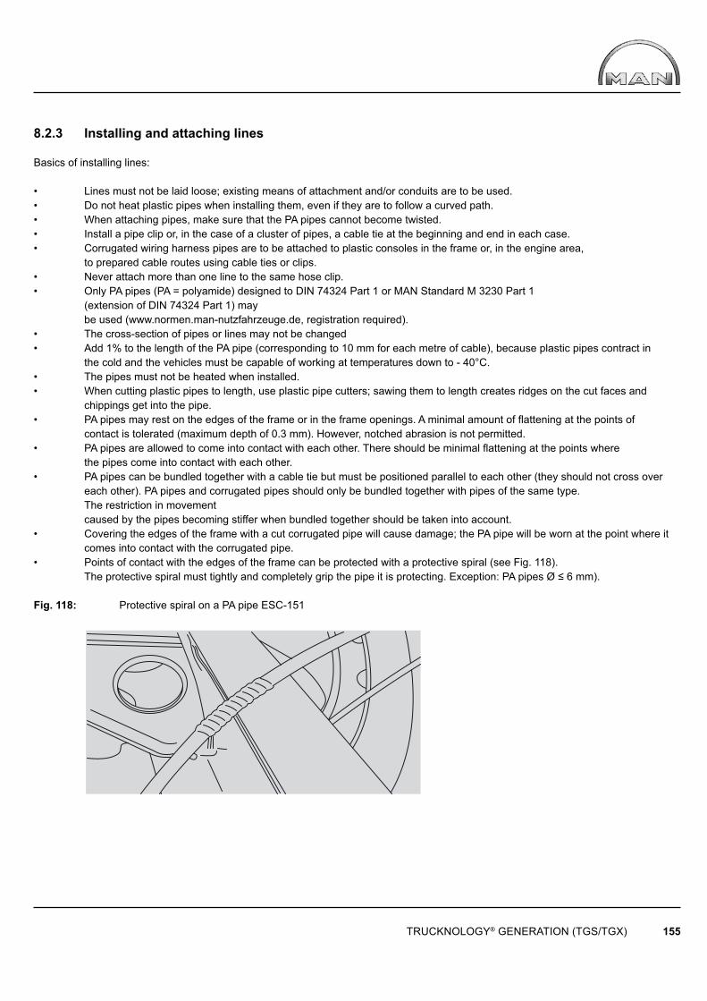
TRUCKNOLOGY® GENERATION (TGS/TGX) 155
8.2.3 Installing and attaching lines
Basics of installing lines:
• Lines must not be laid loose; existing means of attachment and/or conduits are to be used.• Do not heat plastic pipes when installing them, even if they are to follow a curved path.• When attaching pipes, make sure that the PA pipes cannot become twisted.• Install a pipe clip or, in the case of a cluster of pipes, a cable tie at the beginning and end in each case.• Corrugated wiring harness pipes are to be attached to plastic consoles in the frame or, in the engine area, to prepared cable routes using cable ties or clips.• Never attach more than one line to the same hose clip.• Only PA pipes (PA = polyamide) designed to DIN 74324 Part 1 or MAN Standard M 3230 Part 1 (extension of DIN 74324 Part 1) may be used (www.normen.man-nutzfahrzeuge.de, registration required).• The cross-section of pipes or lines may not be changed • Add 1% to the length of the PA pipe (corresponding to 10 mm for each metre of cable), because plastic pipes contract in the cold and the vehicles must be capable of working at temperatures down to - 40°C.• The pipes must not be heated when installed.• When cutting plastic pipes to length, use plastic pipe cutters; sawing them to length creates ridges on the cut faces and chippings get into the pipe.• PA pipes may rest on the edges of the frame or in the frame openings. A minimal amount of fl attening at the points of contact is tolerated (maximum depth of 0.3 mm). However, notched abrasion is not permitted.• PA pipes are allowed to come into contact with each other. There should be minimal fl attening at the points where the pipes come into contact with each other.• PA pipes can be bundled together with a cable tie but must be positioned parallel to each other (they should not cross over each other). PA pipes and corrugated pipes should only be bundled together with pipes of the same type. The restriction in movement caused by the pipes becoming stiffer when bundled together should be taken into account.• Covering the edges of the frame with a cut corrugated pipe will cause damage; the PA pipe will be worn at the point where it comes into contact with the corrugated pipe.• Points of contact with the edges of the frame can be protected with a protective spiral (see Fig. 118). The protective spiral must tightly and completely grip the pipe it is protecting. Exception: PA pipes Ø ≤ 6 mm).
Fig. 118: Protective spiral on a PA pipe ESC-151

TRUCKNOLOGY® GENERATION (TGS/TGX) 156
• PA pipes/PA corrugated pipes must not come into contact with aluminium alloys, e.g. aluminium tank, fuel fi lter housing; aluminium alloys are subject to mechanical wear (fi re risk).• Pipes that cross over and pulsate (e.g. fuel pipes) must not be joined together with a cable tie at the cross-over point (risk of chafi ng).• No cables/pipes should be fi xed rigidly to injection pipes and steel fuel feed pipes for the fl ame starting system (fi re risk, risk of chafi ng).• Accompanying central lubricating cables and ABS sensor cables may be attached to air hoses only if a rubber spacer is fi tted.• Nothing may be attached to coolant hoses and hydraulic hoses (e.g. steering hoses) by means of cable ties (risk of chafi ng).• Under no circumstances should starter cables be bundled together with fuel or oil pipes; this is because it is essential that the cable from the positive terminal does not chafe.• Effects of heat: watch out for a build-up of heat in encapsulated areas. Resting the pipes/cables on heat shields is not permitted (minimum distance from heat shields ≥ 100 mm, from the exhaust ≥ 200 mm)• Metal pipes are pre-strengthened and must not be bent or installed in such a way that they bend during operation.
If assemblies/components are mounted in such a way that they can move with respect to each other, then the following basic rules must be followed when routing cables/pipes:
• The cable/pipe must be able to follow the movement of the assembly without any problem; ensure that there is suffi cient distance between the moving parts for this (rebound/compression, steering angle, tilting of cab). The cables must not be stretched.• The respective starting and end point of the movement is to be defi ned exactly and used as the fi xed clamping point. The PA or corrugated pipe is gripped tightly at the clamping point using the widest cable tie possible or a clip suitable for the diameter of the pipe.• If PA and corrugated pipes are laid at the same junction, the stiffer PA pipe is laid fi rst. The softer corrugated pipe is then attached to the PA pipe.• If a pipe is to tolerate movements at right angles to the direction in which it is laid, then suffi cient distance between the clamping points must be guaranteed (rule of thumb: distance between clamping points ≥ 5 x the amplitude of movement to be withstood).• Large amplitudes of movement are best withstood by laying the pipe in a U-shape and by permitting movement along the arms of the „U“. Rule of thumb for the minimum length of the slack loop:Minimum length of the slack loop = 1/2 · amplitude of movement · minimum radius · π
• The following minimum radii are to be observed for PA pipes (the respective start and end point of the movement is to be defi ned precisely as the fi xed clamping point):
Table 32: Minimum bending radii for PA pipes
Nominal pipe diameter - Ø [ mm ] 4 6 9 12 14 16Bending radius r ≥ [ mm ] 20 30 40 60 80 95
• Use plastic clips to secure the lines and comply with the maximum clip spacing stated in Table 33.
Table 33: Maximum space between clips used to secure pipes in relation to pipe size
Pipe size 4 x 1 6 x 1 8 x 1 9 x 1,5 11 x 1,5 12 x 1,5 14 x 2 14 x 2,5 16 x 2Clip spacing [mm] 500 500 600 600 700 700 800 800 800
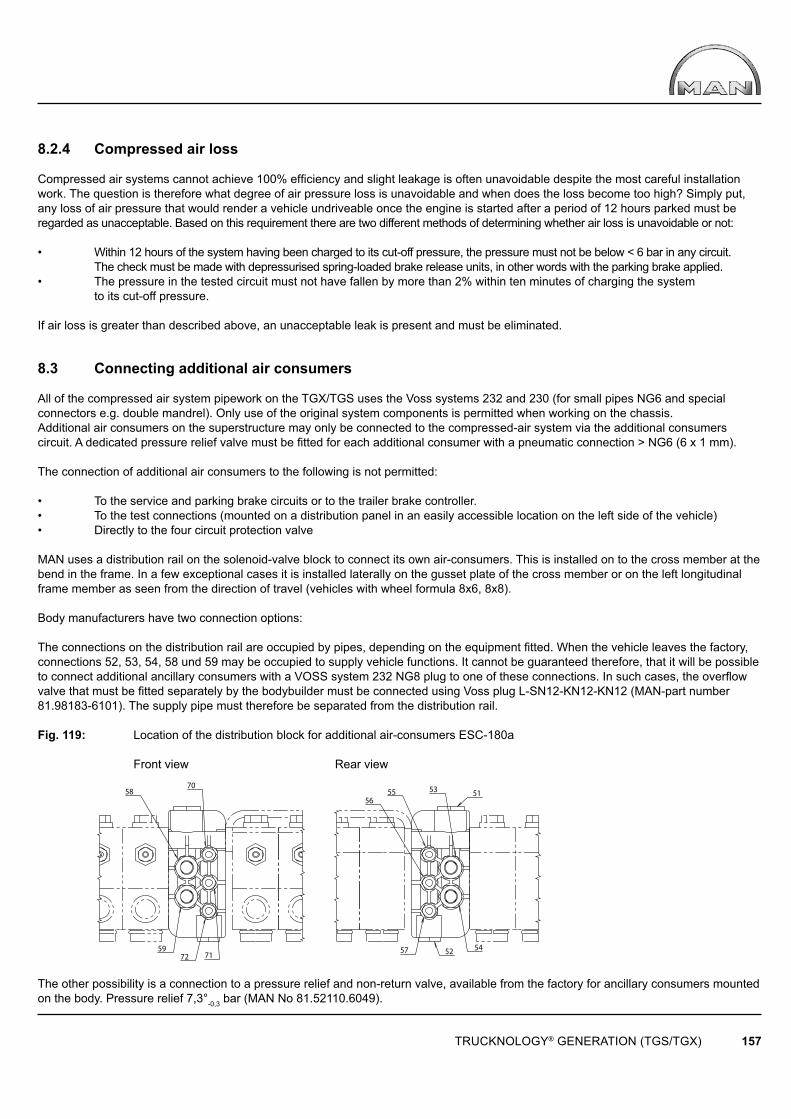
51
52
70
7259
58
71
53
57
55
54
56
TRUCKNOLOGY® GENERATION (TGS/TGX) 157
8.2.4 Compressed air loss Compressed air systems cannot achieve 100% effi ciency and slight leakage is often unavoidable despite the most careful installation work. The question is therefore what degree of air pressure loss is unavoidable and when does the loss become too high? Simply put, any loss of air pressure that would render a vehicle undriveable once the engine is started after a period of 12 hours parked must be regarded as unacceptable. Based on this requirement there are two different methods of determining whether air loss is unavoidable or not:
• Within 12 hours of the system having been charged to its cut-off pressure, the pressure must not be below < 6 bar in any circuit. The check must be made with depressurised spring-loaded brake release units, in other words with the parking brake applied.• The pressure in the tested circuit must not have fallen by more than 2% within ten minutes of charging the system to its cut-off pressure.
If air loss is greater than described above, an unacceptable leak is present and must be eliminated.
8.3 Connecting additional air consumers
All of the compressed air system pipework on the TGX/TGS uses the Voss systems 232 and 230 (for small pipes NG6 and special connectors e.g. double mandrel). Only use of the original system components is permitted when working on the chassis.Additional air consumers on the superstructure may only be connected to the compressed-air system via the additional consumers circuit. A dedicated pressure relief valve must be fi tted for each additional consumer with a pneumatic connection > NG6 (6 x 1 mm).
The connection of additional air consumers to the following is not permitted:
• To the service and parking brake circuits or to the trailer brake controller.• To the test connections (mounted on a distribution panel in an easily accessible location on the left side of the vehicle)• Directly to the four circuit protection valve
MAN uses a distribution rail on the solenoid-valve block to connect its own air-consumers. This is installed on to the cross member at the bend in the frame. In a few exceptional cases it is installed laterally on the gusset plate of the cross member or on the left longitudinal frame member as seen from the direction of travel (vehicles with wheel formula 8x6, 8x8).
Body manufacturers have two connection options:
The connections on the distribution rail are occupied by pipes, depending on the equipment fi tted. When the vehicle leaves the factory, connections 52, 53, 54, 58 und 59 may be occupied to supply vehicle functions. It cannot be guaranteed therefore, that it will be possible to connect additional ancillary consumers with a VOSS system 232 NG8 plug to one of these connections. In such cases, the overfl ow valve that must be fi tted separately by the bodybuilder must be connected using Voss plug L-SN12-KN12-KN12 (MAN-part number 81.98183-6101). The supply pipe must therefore be separated from the distribution rail.
Fig. 119: Location of the distribution block for additional air-consumers ESC-180a
Front view Rear view
The other possibility is a connection to a pressure relief and non-return valve, available from the factory for ancillary consumers mounted on the body. Pressure relief 7,3°-0,3 bar (MAN No 81.52110.6049).
TRUCKNOLOGY® GENERATION (TGS/TGX) 158
8.4 Retrofi tting continuous brakes not manufactured by MAN
Fitting continuous braking systems (retarders, eddy current brakes) that have not been documented by MAN is fundamentally not possible. Retrofi tting of continuous brakes not manufactured by MAN is not permitted because the necessary intervention in the electronically controlled braking system (EBS) and the vehicle’s on-board braking and drivetrain management system is not permitted.
9. Calculations
9.1 Speed
The following generally applies for the calculation of the driving speed on the basis of engine speed, tyre size and overall ratio:
Formula 18: Speed 0,06 • nMot • U v = iG • iv • iA
Where:
v = Driving speed, in [km/h] nMot = Engine speed, in [rpm] U = Tyre rolling circumference, in [m] IG = Transmission ratio iV = Transfer case ratio iA = Final drive ratio of the driven axle(s)
To calculate the theoretical maximum speed (or the design top speed), the engine speed is increased by 4%. The formula therefore is as follows:
Formula 19: Theoretical maximum speed
0,0624 • nMot • U v = iG • iv • iA Caution: This calculation is used exclusively to calculate the theoretical fi nal speed on the basis of engine speed andtransmission ratios. The formula does not take into consideration the fact that the actual maximum speed will be below this speed when driving resistances offset the driving forces. An estimate of the actual achievable speeds using a driving performance calculation in which air, rolling and climbing resistance on the one side and tractive force on the other offset each other, can be found in Section 9.8, „Driving resistances“. On vehicles with a speed limiter in accordance with 92/24/EEC, the design top speed is generally 90 km/h.
Example of a calculation: Vehicle: Model 56S TGS 33.430 6x6 BB Tyre size: 315/80 R 22,5 Rolling circumference: 3,280 m Transmission: ZF 16S 2522 TO Transmission ratio in lowest gear: 13,80 Transmission ratio in highest gear: 0,84 Minimum engine speed at maximum engine torque: 1.000/min Maximum engine speed: 1.900/min Ratio for transfer case G 172 in on-road applications: 1,007 Ratio for transfer case G 172 in off-road applications: 1,652 Final drive ratio: 4,00
TRUCKNOLOGY® GENERATION (TGS/TGX) 159
The solution to following is required:
1. Minimum speed in off-road applications at maximum torque
2. Theoretical maximum speed without speed limiter
Solution 1:
0,06 • 1000 • 3,280 v = 13,8 • 1,652 • 4,00
v = 2,16 km/h
Solution 2:
0,0624 • 1900 • 3,280 v = 0,84 • 1,007 • 4,00
v = 115 km/h
A speed of 115km/h is theoretically possible, however the speed limiter limits this to 90km/h.(The speed is actually set to 89km/h as a result of the tolerances that must be taken into account).
9.2 Efficiency
The efficiency is the ratio of the power output to the power input. Since the power output is always smaller than the power input, efficiency η is always < 1 or < 100%.
Formula 20: Efficiency Pab η = Pzu
When several units are connected in series, the individual efficiencies are multiplied.
Example of a calculation for individual efficiency:
Efficiency of a hydraulic pump η = 0,7. If the required power output Pab is 20 kW, what should the power input Pzu be?
Solution:
Pab Pzu = η
20 Pzu = 0,7
Pzu = 28,6 kW
TRUCKNOLOGY® GENERATION (TGS/TGX) 160
Example of calculation for several effi ciencies:
Effi ciency of a hydraulic pump η1 = 0,7. This pump drives a hydraulic motor via a jointed shaft system with two joints.
Individual effi ciencies: Hydraulic pump: η1 = 0,7 Jointed shaft joint a: η2 = 0,95 Jointed shaft joint b: η3 = 0,95 Hydraulic motor: η4 = 0,8
Power required, i.e., power output Pab = 20 kW
What is the power input Pzu?
Solution:
Overall effi ciency:
ηges = η1 • η2 • η3 • η4
ηges = 0,7 • 0,95 • 0,95 • 0,8
ηges = 0,51
Power input: 20 Pzu = 0,51
Pzu = 39,2 kW
9.3 Tractive force
The tractive force is dependent on:
• Engine torque• Overall ratio (including that of the wheels)• Effi ciency of power transmission
Formula 21: Tractive force
2 • � • MMot • η • iG • iV • iA Fz = U
FZ = Tractive force, in [N] MMot = Engine torque, in [Nm] η = Overall effi ciency in the drive train – see guideline values in Table 35 iG = Transmission ratio iV = Transfer case ratio iA = Final drive ratio of the driven axle(s) U = Tyre rolling circumference, in [m]
For an example of tractive force, see 9.4.3 Calculating gradeability.
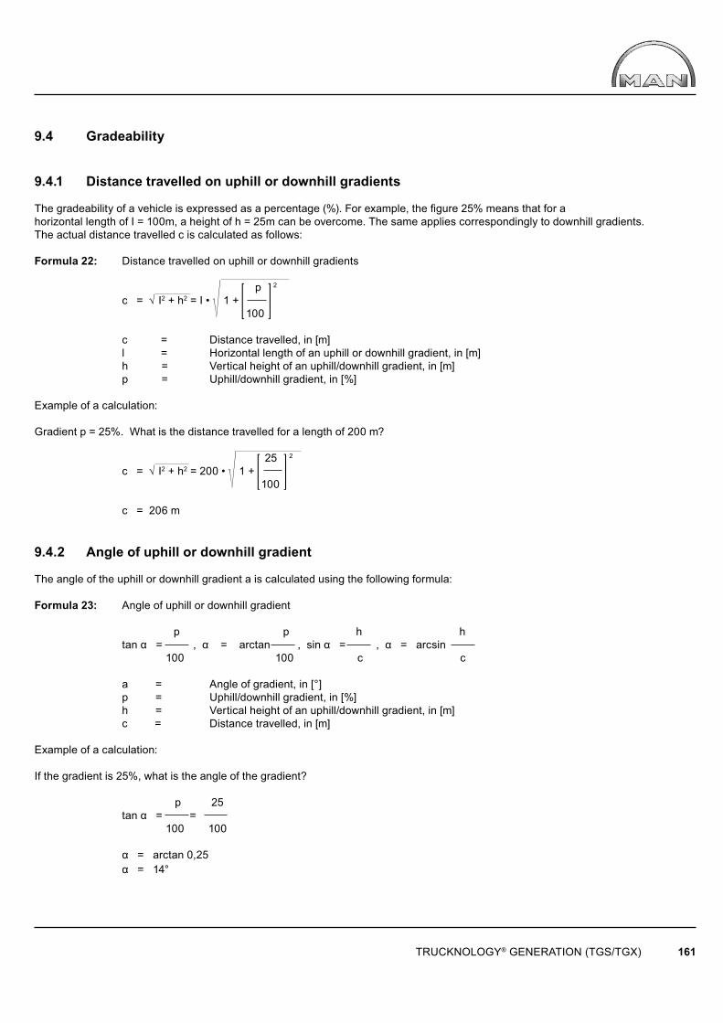
TRUCKNOLOGY® GENERATION (TGS/TGX) 161
9.4 Gradeability
9.4.1 Distance travelled on uphill or downhill gradients
The gradeability of a vehicle is expressed as a percentage (%). For example, the fi gure 25% means that for ahorizontal length of I = 100m, a height of h = 25m can be overcome. The same applies correspondingly to downhill gradients. The actual distance travelled c is calculated as follows:
Formula 22: Distance travelled on uphill or downhill gradients
p 2
c = I2 + h2 = I • 1 + 100 c = Distance travelled, in [m] l = Horizontal length of an uphill or downhill gradient, in [m] h = Vertical height of an uphill/downhill gradient, in [m] p = Uphill/downhill gradient, in [%]
Example of a calculation:
Gradient p = 25%. What is the distance travelled for a length of 200 m?
25 2
c = I2 + h2 = 200 • 1 + 100
c = 206 m
9.4.2 Angle of uphill or downhill gradient
The angle of the uphill or downhill gradient a is calculated using the following formula:
Formula 23: Angle of uphill or downhill gradient
p p h h tan α = , α = arctan , sin α = , α = arcsin 100 100 c c
a = Angle of gradient, in [°] p = Uphill/downhill gradient, in [%] h = Vertical height of an uphill/downhill gradient, in [m] c = Distance travelled, in [m]
Example of a calculation:
If the gradient is 25%, what is the angle of the gradient? p 25 tan α = = 100 100
α = arctan 0,25 α = 14°
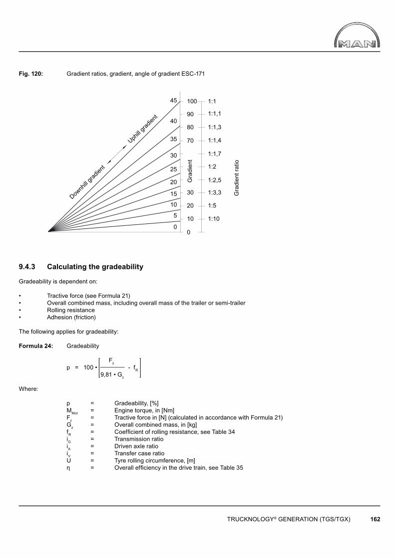
0
5
10
20
40
0
10
20
30
70
80
90
100 1:1
1:1,1
1:1,3
1:1,4
1:1,7
1:2
1:2,5
1:3,3
1:5
1:10
45
30
35
25
15
TRUCKNOLOGY® GENERATION (TGS/TGX) 162
Downh
ill grad
ient
Uph
ill grad
ient
Gra
dien
t
Gra
dien
t rat
io
Fig. 120: Gradient ratios, gradient, angle of gradient ESC-171
9.4.3 Calculating the gradeability
Gradeability is dependent on:
• Tractive force (see Formula 21)• Overall combined mass, including overall mass of the trailer or semi-trailer• Rolling resistance• Adhesion (friction)
The following applies for gradeability:
Formula 24: Gradeability
Fz p = 100 • - fR 9,81 • Gz
Where:
p = Gradeability, [%] MMot = Engine torque, in [Nm] Fz = Tractive force in [N] (calculated in accordance with Formula 21) Gz = Overall combined mass, in [kg] fR = Coeffi cient of rolling resistance, see Table 34 iG = Transmission ratio iA = Driven axle ratio iV = Transfer case ratio U = Tyre rolling circumference, [m] η = Overall effi ciency in the drive train, see Table 35
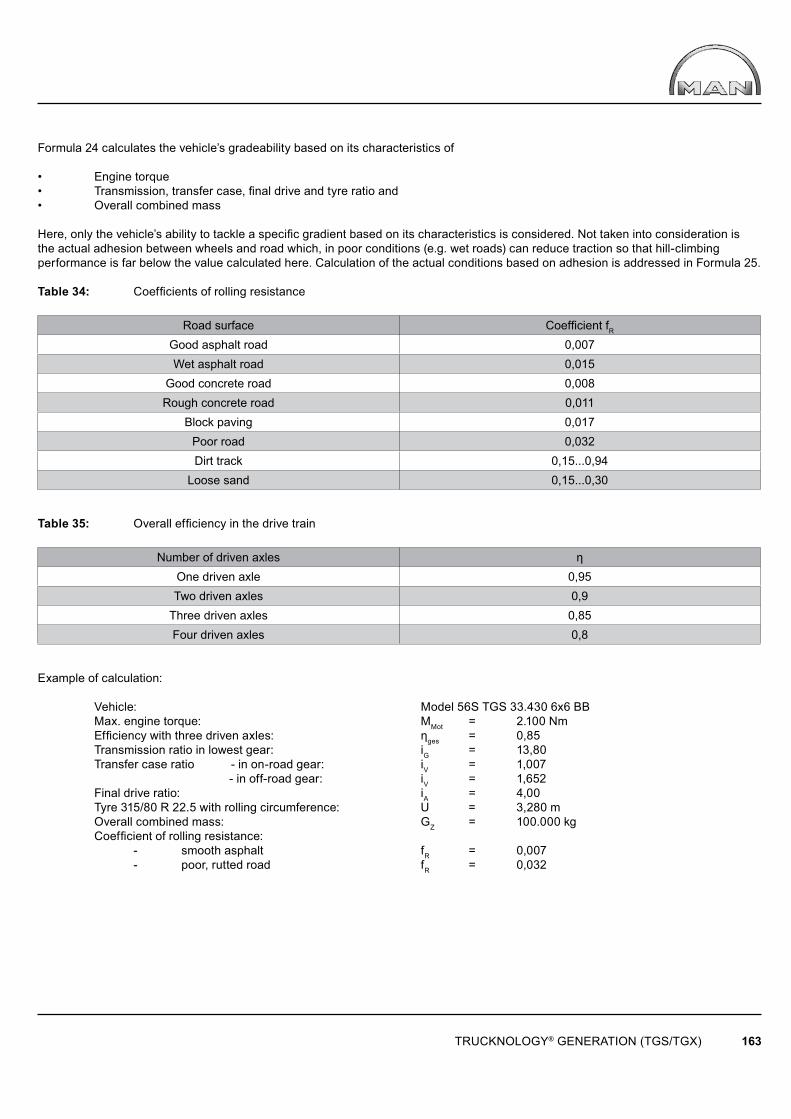
TRUCKNOLOGY® GENERATION (TGS/TGX) 163
Formula 24 calculates the vehicle’s gradeability based on its characteristics of
• Engine torque• Transmission, transfer case, fi nal drive and tyre ratio and• Overall combined mass
Here, only the vehicle’s ability to tackle a specifi c gradient based on its characteristics is considered. Not taken into consideration is the actual adhesion between wheels and road which, in poor conditions (e.g. wet roads) can reduce traction so that hill-climbing performance is far below the value calculated here. Calculation of the actual conditions based on adhesion is addressed in Formula 25.
Table 34: Coeffi cients of rolling resistance
Road surface Coeffi cient fR
Good asphalt road 0,007Wet asphalt road 0,015
Good concrete road 0,008Rough concrete road 0,011
Block paving 0,017Poor road 0,032Dirt track 0,15...0,94
Loose sand 0,15...0,30
Table 35: Overall effi ciency in the drive train
Number of driven axles ηOne driven axle 0,95Two driven axles 0,9
Three driven axles 0,85Four driven axles 0,8
Example of calculation: Vehicle: Model 56S TGS 33.430 6x6 BB Max. engine torque: MMot = 2.100 Nm Effi ciency with three driven axles: ηges = 0,85 Transmission ratio in lowest gear: iG = 13,80 Transfer case ratio - in on-road gear: iV = 1,007 - in off-road gear: iV = 1,652 Final drive ratio: iA = 4,00 Tyre 315/80 R 22.5 with rolling circumference: U = 3,280 m Overall combined mass: GZ = 100.000 kg Coeffi cient of rolling resistance: - smooth asphalt fR = 0,007 - poor, rutted road fR = 0,032
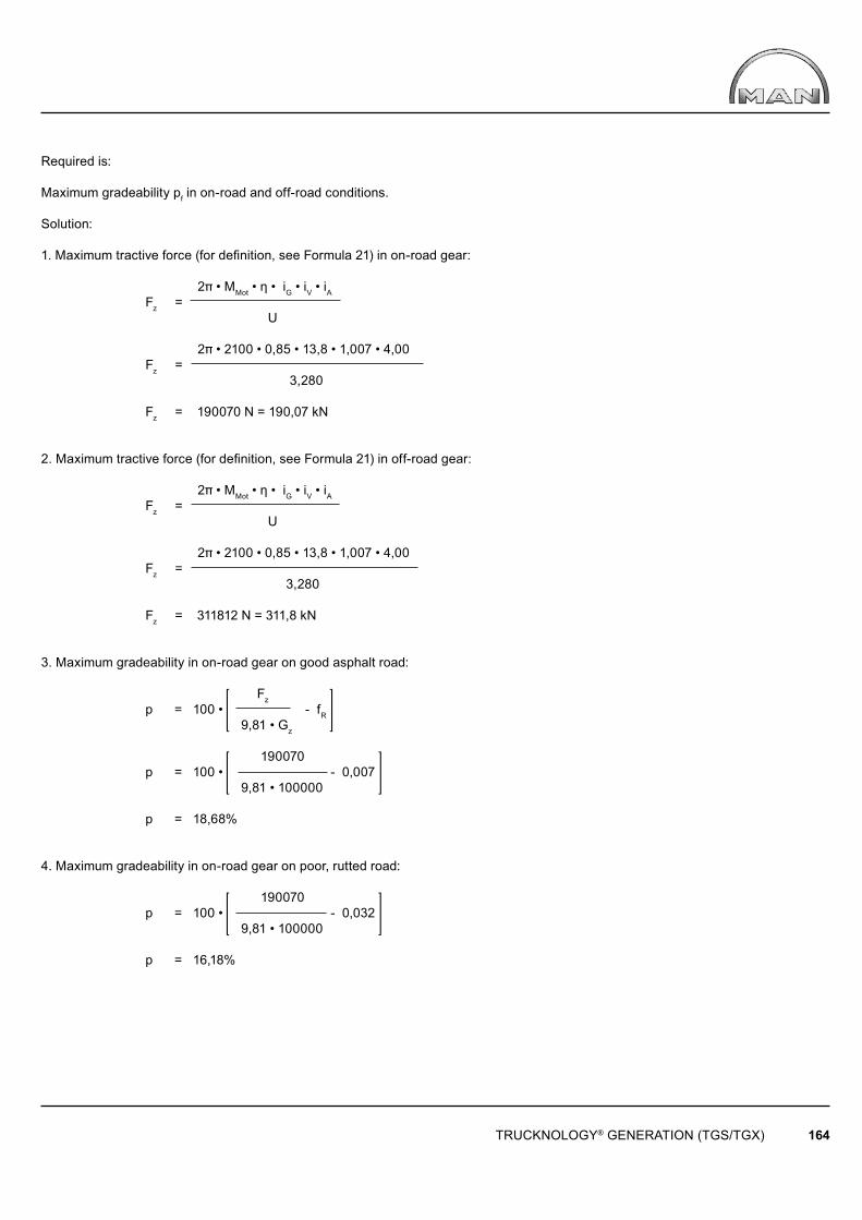
TRUCKNOLOGY® GENERATION (TGS/TGX) 164
Required is:
Maximum gradeability pf in on-road and off-road conditions.
Solution:
1. Maximum tractive force (for defi nition, see Formula 21) in on-road gear:
2� • MMot • η • iG • iV • iA Fz = U
2� • 2100 • 0,85 • 13,8 • 1,007 • 4,00 Fz = 3,280
Fz = 190070 N = 190,07 kN
2. Maximum tractive force (for defi nition, see Formula 21) in off-road gear:
2� • MMot • η • iG • iV • iA Fz = U
2� • 2100 • 0,85 • 13,8 • 1,007 • 4,00 Fz = 3,280
Fz = 311812 N = 311,8 kN
3. Maximum gradeability in on-road gear on good asphalt road: Fz p = 100 • - fR 9,81 • Gz
190070 p = 100 • - 0,007 9,81 • 100000
p = 18,68%
4. Maximum gradeability in on-road gear on poor, rutted road: 190070 p = 100 • - 0,032 9,81 • 100000
p = 16,18%
TRUCKNOLOGY® GENERATION (TGS/TGX) 165
5. Maximum gradeability in off-road gear on good asphalt road: 311812 p = 100 • - 0,007 9,81 • 100000
p = 31,09%
6. Maximum gradeability in off-road gear on poor, rutted road:
311812 p = 100 • - 0,032 9,81 • 100000
p = 28,58%
Note:
The examples shown do not take into consideration whether adhesion between road and driven wheels (friction) will allow the tractive force required for tackling the gradient to be transmitted. The following formula is applied for this:
Formula 25: Gradeability taking into account road/tyre adhesion
μ • Gan pR = 100 • - fR Gz Where: pR = Gradeability taking friction into account, in [%] μ = Tyre/road surface coeffi cient of friction, on wet asphalt surface ~ 0,5 fR = Coeffi cient of rolling resistance, on wet asphalt road surface ~ 0,015 Gan = Sum of the axle loads of the driven axles as mass, in [kg] GZ = Overall combined mass, in [kg]
Example of calculation: Above vehicle: Model 56S TGS 33.430 6x6 BB Coeffi cient, wet asphalt road: μ = 0,5 Coeffi cient of rolling resistance, wet asphalt: fR = 0,015 Overall combined mass: GZ = 100.000 kg Sum of the axle loads of all driven axles: Gan = 26.000 kg
0,5 • 26000 pR = 100 • - 0,015 100000
pR = 11,5%
TRUCKNOLOGY® GENERATION (TGS/TGX) 166
9.5 Torque
If force and effective separation are known:
Formula 26: Torque with force and effective separation M = F • I
If power output and rotational speed are known:
Formula 27: Torque with power output and rotational speed 9550 • P M = n • η
In hydraulic systems, if delivery rate (volume fl ow rate), pressure and rotational speed are known:
Formula 28: Torque with delivery rate, pressure and rotational speed
15,9 • Q • p M = n • η
Where: M = Torque, in [Nm] F = Force, in [N] l = Distance from the line of action of the force to the centre of rotation, in [m] P = Power output, in [kW] n = Rotational speed, in [rpm] η = Efficiency Q = Volume flow rate, in [l/min] p = Pressure, in [bar]
Example of calculation when force and effective separation are known:
A cable winch with a pulling force F of 50,000 N has a drum diameter d = 0.3 m. Without taking efficiency into account, what is the torque?
Solution:
M = F • l = F • 0,5 d (the drum radius is the leverage)
M = 50000N • 0,5 • 0,3 m
M = 7500 Nm
Example when power output and rotational speed are known:
A power take-off is to transmit a power P of 100 kW at n = 1500/min. Without taking efficiency into account, what torque must the power take-off be able to transmit?
TRUCKNOLOGY® GENERATION (TGS/TGX) 167
Solution: 9550 • 100 M = 1500
M = 637 Nm
Example if delivery rate (volume fl ow rate), pressure and rotational speed are known for a hydraulic pump:
A hydraulic pump delivers a volume fl ow rate Q of 80 l/min at a pressure p of 170 bar and a pump rotational speed n of 1000/min. Without taking effi ciency into account, what torque is required?
Solution: 15,9 • 80 • 170 M = 1000
M = 216 Nm
If effi ciency is to be taken into account, the torques calculated in each case must be divided by the overall effi ciency (see also Section 9.2, Effi ciency).
9.6 Power output
For lifting motion:
Formula 29: Power output for lifting motion 9,81 • m • v M = 1000 • η
For plane motion:
Formula 30: Power output for plane motion
F • v P = 1000 • η
For rotational motion:
Formula 31: Power output for rotational motion
M • n P = 9550 • η
TRUCKNOLOGY® GENERATION (TGS/TGX) 168
In hydraulic systems:
Formula 32: Power output in hydraulic systems
Q • p P = 600 • η
Where:
P = Power output, in [kW] m = Mass, in [kg] v = Speed, in [m/s] η = Effi ciency F = Force, in [N] M = Torque, in [Nm] n = Rotational speed, in [rpm] Q = Delivery rate (volume fl ow rate), in [l/min] p = Pressure, in [bar]
Example 1 = Lifting motion:
Tail-lift payload including its own weight m = 2. 600 kgLift speed v = 0,2 m/s
If effi ciency is not taken into consideration, what is the power output?
Solution: 9,81 • 2600 • 0,2 P = 1000
P = 5,1 kW
Example 2: Plane motion:
Cable winch F = 100.000 NCable speed v = 0,15 m/s
If effi ciency is not taken into consideration, what is the power output requirement? 100000 • 0,15 P = 1000
P = 15 kW
Example 3 – Rotational motion:
Power take-off rotational speed n = 1.800/minPermissible torque M = 600 Nm
TRUCKNOLOGY® GENERATION (TGS/TGX) 169
If effi ciency is not taken into consideration, what power output is possible?
Solution:
600 • 1800 P = 9550
P = 113 kW
Example 4: Hydraulic system:
Volume flow rate of the pump Q = 60 l/minPressure p = 170 bar
If efficiency is not taken into consideration, what is the power output?
Solution:
60 • 170 P = 600
P = 17 kW
9.7 Rotational speeds for power take-offs at the transfer case
If the power take-off is operating on the transfer case and its operation is distance-dependent, its rotational speed nN is given in revolutions per metre of distance covered. It is calculated from the following:
Formula 33: Revolutions per meter, power take-off at the transfer box
iA • iV nN = U
The distance s in metres covered per revolution of the power take-off (reciprocal value of nN) is calculated with:
Formula 34: Distance per revolution, power take-off on the transfer case U s = iA • iVWhere:
nN = Power take-off rotational speed, in [1/m] iA = Final drive ratio iV = Transfer case ratio U = Tyre circumference, in [m] s = Distance travelled, in [m]
Example:
Vehicle: Model 80S TGS 18.480 4x4 BL Tyres 315/80 R22.5 with rolling circumference: U = 3,280 m Final drive ratio: iA = 5,33 Transfer case G172, ratio in on-road gear: iv = 1,007 Ratio in off-road applications: iv = 1,652
TRUCKNOLOGY® GENERATION (TGS/TGX) 170
Power take-off rotational speed in on-road gear:
5,33 • 1,007 nN = 3,280
nN = 1,636/m
This corresponds to a distance of: 3,280 s = 5,33 • 1,007
s = 0,611 m
Power take-off rotational speed in off-road gear:
5,33 • 1,652 nN = 3,280 nN = 2,684 m
This corresponds to a distance of:
3,280 s = 5,33 • 1,652
s = 0,372 m
9.8 Driving resistances
The main driving resistances are:
• Rolling resistance• Climbing resistance• Air resistance (drag).
A vehicle can move along only if the sum of all resistances is overcome. Resistances are forces that either balance out the driving force (uniform movement) or are smaller than the driving force (accelerated movement).
Formula 35: Rolling resistance force
FR = 9,81 • fR • Gz • cosα
Formula 36: Climbing resistance force
FS = 9,81 • Gz • sinα
TRUCKNOLOGY® GENERATION (TGS/TGX) 171
Angle of gradient (= formula 23, see Section 9.4.2, Angle of uphill and downhill gradients)
p p tan α = , α = arctan 100 100
Formula 37: Air resistance force
FL = 0,6 • cW • A • v2
Where:
FR = Rolling resistance force, in [N] fR = Coeffi cient of rolling resistance, see Table 34 GZ = Overall combined mass, in [kg] α = Angle of uphill gradient, in [°] FS = Climbing resistance force, in [N] p = Uphill gradient, in [%] FL = Air resistance force, in [N] cW = Drag coeffi cient A = Vehicle frontal area, in [m²] v = Speed, in [m/s]
Example:
Articulated vehicle: GZ = 40.000 kg Speed: v = 80 km/h Gradient: pf = 3% Vehicle frontal area: A = 7 m² Coeffi cient of rolling resistance for good asphalt road: fR = 0,007
A distinction is to be made between the following:
• with spoiler, cW1 = 0,6• without spoiler, cW2 = 1,0
Solution:
Additional calculation 1:
Conversion of driving speed from km/h into m/s: 80 v = = 22,22m/s 3,6
Additional calculation 2:
Conversion of gradeability from % into degrees:
3 α = arctan = arctan 0,03 100
α = 1,72°

TRUCKNOLOGY® GENERATION (TGS/TGX) 172
1. Calculation of rolling resistance: FR = 9,81 • 0,007 • 40000 • cos 1,72°
FR = 2746 N
2. Calculation of climbing resistance: FS = 9,81 • 40000 • sin 1,72°
FS = 11778 N
3. Calculation of air resistance FL1 with spoiler:
FL1 = 0,6 • 0,6 • 7 • 22,222
FL1 = 1244 N
4. Calculation of air resistance FL2 without spoiler: FL2 = 0,6 • 1 • 7 • 22,222
FL2 = 2074 N
5. Overall resistance Fges1 with spoiler:
Fges1 = FR + Fs + FL1 Fges1 = 2746 + 11778 + 1244 Fges1 = 15768 N 6. Overall resistance Fges2 without spoiler:
Fges2 = FR + Fs + FL2 Fges2 = 2746 + 11778 + 2074 Fges2 = 16598 N
7. Power output requirement P1 with spoiler, not taking effi ciency into consideration:
(power output in accordance with Formula 30, Power output for plane motion)
Fges1 • v P1‘ = 1000
15768 • 22,22 P1‘ = 1000
P1‘ = 350 kW (476 PS)

TRUCKNOLOGY® GENERATION (TGS/TGX) 173
8. Power output requirement P2 without spoiler, not taking effi ciency into consideration:
Fges2 • v P2‘ = 1000
16598 • 22,22 P2‘ = 1000
P2‘ = 369 kW (502 PS)
9. Power output requirement P1 with spoiler and overall driveline effi ciency of η = 0,95: P1‘ 350 P1 = = η 0,95
P1 = 368 kW (501 PS)
10. Power output requirement P2 with spoiler and overall driveline effi ciency of η = 0,95:
P2‘ 369 P2 = = η 0,95
P2 = 388 kW (528 PS)
9.9 Turning circle
When a vehicle is cornering, each wheel describes a turning circle. The outer turning circle, or its radius, is the main subject of interest. The calculation is not precise because when a vehicle is cornering the perpendiculars through the centres of all wheels do not intersect at the curve centre point (Ackermann condition). In addition, while the vehicle is moving dynamic forces will arise that will affect the cornering manoeuvre. However, the following formulae can be used for estimation purposes:
Formula 38: Distance between steering axes
j = s - 2ro
Formula 39: Theoretical value of the outer steer angle
j cotßao = cotßi + lkt
Formula 40: Steer angle deviation ßF = ßa - ßao
Formula 41: Turning circle radius
lkt rs = + ro - 50 • ßF
sinßao
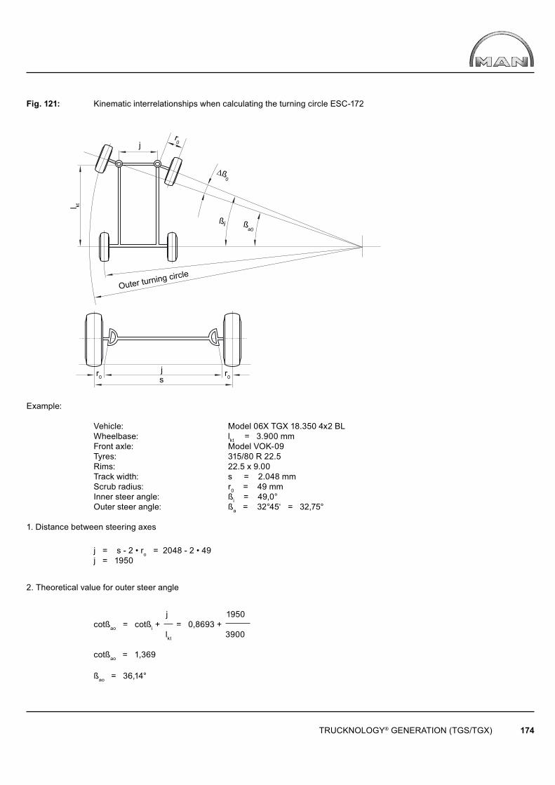
l kt
j
js
ßa0
ßi
r0
r0r0
Ƨ0
TRUCKNOLOGY® GENERATION (TGS/TGX) 174
Outer turning circle
Fig. 121: Kinematic interrelationships when calculating the turning circle ESC-172
Example: Vehicle: Model 06X TGX 18.350 4x2 BL Wheelbase: lkt = 3.900 mm Front axle: Model VOK-09 Tyres: 315/80 R 22.5 Rims: 22.5 x 9.00 Track width: s = 2.048 mm Scrub radius: r0 = 49 mm Inner steer angle: ßi = 49,0° Outer steer angle: ßa = 32°45‘ = 32,75°
1. Distance between steering axes
j = s - 2 • ro = 2048 - 2 • 49 j = 1950
2. Theoretical value for outer steer angle
j 1950 cotßao = cotßi + = 0,8693 + lkt 3900
cotßao = 1,369
ßao = 36,14°
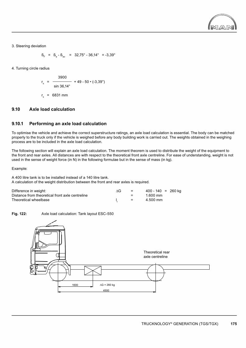
1600
4500
∆G = 260 kg
TRUCKNOLOGY® GENERATION (TGS/TGX) 175
Theoretical rear axle centreline
3. Steering deviation
ßF = ßa - ßao = 32,75° - 36,14° = -3,39°
4. Turning circle radius
3900 rs = + 49 - 50 • (-3,39°) sin 36,14° rs = 6831 mm
9.10 Axle load calculation
9.10.1 Performing an axle load calculation
To optimise the vehicle and achieve the correct superstructure ratings, an axle load calculation is essential. The body can be matched properly to the truck only if the vehicle is weighed before any body building work is carried out. The weights obtained in the weighing process are to be included in the axle load calculation.
The following section will explain an axle load calculation. The moment theorem is used to distribute the weight of the equipment to the front and rear axles. All distances are with respect to the theoretical front axle centreline. For ease of understanding, weight is not used in the sense of weight force (in N) in the following formulae but in the sense of mass (in kg).
Example:
A 400 litre tank is to be installed instead of a 140 litre tank. A calculation of the weight distribution between the front and rear axles is required.
Difference in weight: ∆G = 400 - 140 = 260 kgDistance from theoretical front axle centreline = 1.600 mmTheoretical wheelbase lt = 4.500 mm
Fig. 122: Axle load calculation: Tank layout ESC-550
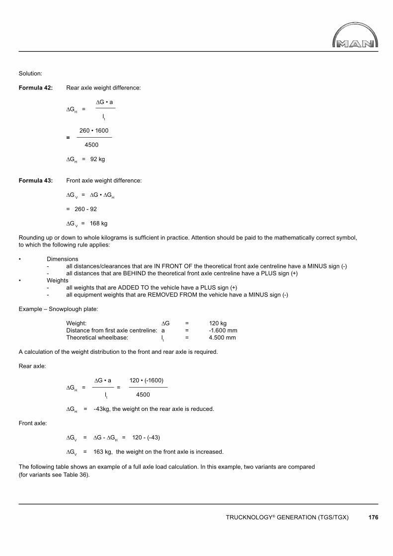
TRUCKNOLOGY® GENERATION (TGS/TGX) 176
Solution:
Formula 42: Rear axle weight difference: ∆G • a ∆GH = lt 260 • 1600 = 4500
∆GH = 92 kg
Formula 43: Front axle weight difference:
∆G V = ∆G • ∆GH = 260 - 92
∆G V = 168 kg
Rounding up or down to whole kilograms is suffi cient in practice. Attention should be paid to the mathematically correct symbol, to which the following rule applies:
• Dimensions - all distances/clearances that are IN FRONT OF the theoretical front axle centreline have a MINUS sign (-) - all distances that are BEHIND the theoretical front axle centreline have a PLUS sign (+)• Weights - all weights that are ADDED TO the vehicle have a PLUS sign (+) - all equipment weights that are REMOVED FROM the vehicle have a MINUS sign (-)
Example – Snowplough plate: Weight: ∆G = 120 kg Distance from fi rst axle centreline: a = -1.600 mm Theoretical wheelbase: lt = 4.500 mm
A calculation of the weight distribution to the front and rear axle is required.
Rear axle:
∆G • a 120 • (-1600) ∆GH = = lt 4500
∆GH = -43kg, the weight on the rear axle is reduced.
Front axle:
∆GV = ∆G - ∆GH = 120 - (-43)
∆GV = 163 kg, the weight on the front axle is increased.
The following table shows an example of a full axle load calculation. In this example, two variants are compared (for variants see Table 36).
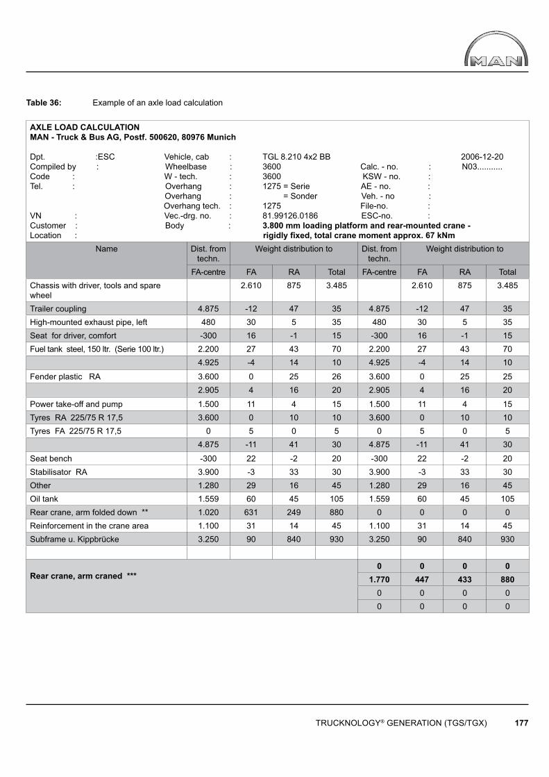
TRUCKNOLOGY® GENERATION (TGS/TGX) 177
Table 36: Example of an axle load calculation
AXLE LOAD CALCULATION MAN - Truck & Bus AG, Postf. 500620, 80976 Munich
Dpt. :ESC Vehicle, cab : TGL 8.210 4x2 BB 2006-12-20Compiled by : Wheelbase : 3600 Calc. - no. : N03...........Code : W - tech. : 3600 KSW - no. : Tel. : Overhang : 1275 = Serie AE - no. : Overhang : = Sonder Veh. - no : Overhang tech. : 1275 File-no. : VN : Vec.-drg. no. : 81.99126.0186 ESC-no. : Customer : Body : 3.800 mm loading platform and rear-mounted crane -Location : rigidly fi xed, total crane moment approx. 67 kNm
Name Dist. from techn.
Weight distribution to Dist. from techn.
Weight distribution to
FA-centre FA RA Total FA-centre FA RA TotalChassis with driver, tools and spare wheel
2.610 875 3.485 2.610 875 3.485
Trailer coupling 4.875 -12 47 35 4.875 -12 47 35High-mounted exhaust pipe, left 480 30 5 35 480 30 5 35Seat for driver, comfort -300 16 -1 15 -300 16 -1 15Fuel tank steel, 150 ltr. (Serie 100 ltr.) 2.200 27 43 70 2.200 27 43 70
4.925 -4 14 10 4.925 -4 14 10
Fender plastic RA 3.600 0 25 26 3.600 0 25 252.905 4 16 20 2.905 4 16 20
Power take-off and pump 1.500 11 4 15 1.500 11 4 15Tyres RA 225/75 R 17,5 3.600 0 10 10 3.600 0 10 10Tyres FA 225/75 R 17,5 0 5 0 5 0 5 0 5
4.875 -11 41 30 4.875 -11 41 30
Seat bench -300 22 -2 20 -300 22 -2 20Stabilisator RA 3.900 -3 33 30 3.900 -3 33 30Other 1.280 29 16 45 1.280 29 16 45Oil tank 1.559 60 45 105 1.559 60 45 105Rear crane, arm folded down ** 1.020 631 249 880 0 0 0 0Reinforcement in the crane area 1.100 31 14 45 1.100 31 14 45Subframe u. Kippbrücke 3.250 90 840 930 3.250 90 840 930
Rear crane, arm craned ***0 0 0 0
1.770 447 433 8800 0 0 00 0 0 0
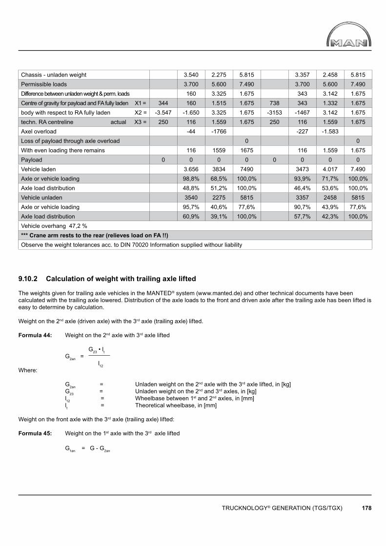
TRUCKNOLOGY® GENERATION (TGS/TGX) 178
Chassis - unladen weight 3.540 2.275 5.815 3.357 2.458 5.815Permissible loads 3.700 5.600 7.490 3.700 5.600 7.490Difference between unladen weight & perm. loads 160 3.325 1.675 343 3.142 1.675Centre of gravity for payload and FA fully laden X1 = 344 160 1.515 1.675 738 343 1.332 1.675body with respect to RA fully laden X2 = -3.547 -1.650 3.325 1.675 -3153 -1467 3.142 1.675techn. RA centreline actual X3 = 250 116 1.559 1.675 250 116 1.559 1.675Axel overload -44 -1766 -227 -1.583Loss of payload through axle overload 0 0With even loading there remains 116 1559 1675 116 1.559 1.675Payload 0 0 0 0 0 0 0 0Vehicle laden 3.656 3834 7490 3473 4.017 7.490Axle or vehicle loading 98,8% 68,5% 100,0% 93,9% 71,7% 100,0%Axle load distribution 48,8% 51,2% 100,0% 46,4% 53,6% 100,0%Vehicle unladen 3540 2275 5815 3357 2458 5815Axle or vehicle loading 95,7% 40,6% 77,6% 90,7% 43,9% 77,6%Axle load distribution 60,9% 39,1% 100,0% 57,7% 42,3% 100,0%Vehicle overhang 47,2 %*** Crane arm rests to the rear (relieves load on FA !!)Observe the weight tolerances acc. to DIN 70020 Information supplied withour liability
9.10.2 Calculation of weight with trailing axle lifted
The weights given for trailing axle vehicles in the MANTED® system (www.manted.de) and other technical documents have been calculated with the trailing axle lowered. Distribution of the axle loads to the front and driven axle after the trailing axle has been lifted is easy to determine by calculation.
Weight on the 2nd axle (driven axle) with the 3rd axle (trailing axle) lifted.
Formula 44: Weight on the 2nd axle with 3rd axle lifted
G23 • lt G2an = l12Where:
G2an = Unladen weight on the 2nd axle with the 3rd axle lifted, in [kg] G23 = Unladen weight on the 2nd and 3rd axles, in [kg] l12 = Wheelbase between 1st and 2nd axles, in [mm] lt = Theoretical wheelbase, in [mm]
Weight on the front axle with the 3rd axle (trailing axle) lifted:
Formula 45: Weight on the 1st axle with the 3rd axle lifted
G1an = G - G2an
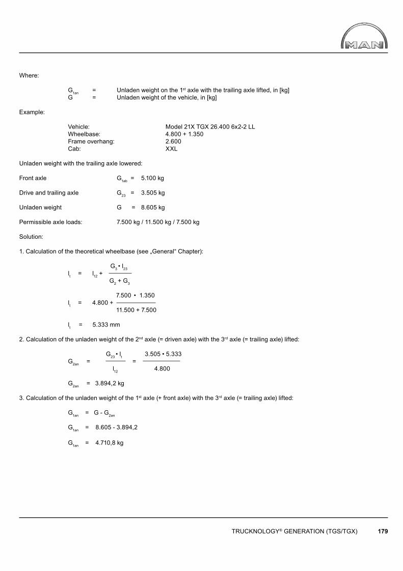
TRUCKNOLOGY® GENERATION (TGS/TGX) 179
Where:
G1an = Unladen weight on the 1st axle with the trailing axle lifted, in [kg] G = Unladen weight of the vehicle, in [kg]
Example:
Vehicle: Model 21X TGX 26.400 6x2-2 LL Wheelbase: 4.800 + 1.350 Frame overhang: 2.600 Cab: XXL
Unladen weight with the trailing axle lowered:
Front axle G1ab = 5.100 kg
Drive and trailing axle G23 = 3.505 kg
Unladen weight G = 8.605 kg Permissible axle loads: 7.500 kg / 11.500 kg / 7.500 kg
Solution:
1. Calculation of the theoretical wheelbase (see „General“ Chapter):
G3 • l23 lt = l12 + G2 + G3
7.500 • 1.350 lt = 4.800 + 11.500 + 7.500
lt = 5.333 mm
2. Calculation of the unladen weight of the 2nd axle (= driven axle) with the 3rd axle (= trailing axle) lifted: G23 • lt 3.505 • 5.333 G2an = = l12 4.800
G2an = 3.894,2 kg
3. Calculation of the unladen weight of the 1st axle (+ front axle) with the 3rd axle (= trailing axle) lifted:
G1an = G - G2an
G1an = 8.605 - 3.894,2 G1an = 4.710,8 kg

TRUCKNOLOGY® GENERATION (TGS/TGX) 180
9.11 Support length for bodies without subframes
The calculation of the required support length in the following example does not take all infl uences into account. However, it does show one option and provides some good reference values for practical applications.
The support length is calculated using the following:
Formula 46: Formula for support length when no subframe is used
0,175 • F • E (rR + rA) l = σ0,2 • rR • rA
If the frame and support are made of different materials, then the following applies:
Formula 47: Modulus of elasticity in the case of different materials 2ER • EA E = ER + EA
Where:
l = Support length for each support, in [mm] F = Force per support, in [N] E = Modulus of elasticity, in [N/mm²] rR = External radius of frame longitudinal member profi le section, in [mm] rA = External radius of support profi le section, in [mm] σ0,2 = Yield point of the lower value material, in [N/mm²] ER = Modulus of elasticity of frame longitudinal member profi le section, in [N/mm²] EA = Modulus of elasticity of support profi le section, in [N/mm²]Example:
Interchangeable body chassis 21X TGX 26.400 6x2-2 LL, wheelbase 4,500 + 1,350, large-capacity cab, permissible gross weight 26,000 kg, chassis unladen weight 8,915 kg.
Solution:
For payload and body there remains approx. 26.000 kg – 8.915 kg = 17.085 kg For each support if there are 6 bearing points on the chassis 17.085: 6 = 2.847 kg Force F = 2.847 kg • 9,81 kg • m/s² = 27.933 N External radius of frame profi le section rR = 18 mm External radius of support profi le section rA = 16 mm Modulus of elasticity for steel E = 210.000 N/mm² Yield point for both materials σ0,2 = 420 N/mm²
Formula 46 can then be used to determine the approximate minimum length for every support:
0,175 • 27.933 • 210.000 • (18+16) l = 4302 • 18 • 16 l = 655 mm
TRUCKNOLOGY® GENERATION (TGS/TGX) 181
9.12 Coupling devices
9.12.1 Trailer coupling
The required trailer coupling size is determined by the D value.
The formula for the D value is as follows:
Formula 48: D value
9,81 • T • R D = T + R
D = D value, in [kN] T = Permissible gross weight of the towing vehicle, in [t] R = Permissible gross weight of the trailer, in [t]
Example:
Vehicle 06X TGX 18.440 4x2 BL
Permissible gross weight 18,000 kg = T = 18t
Trailer load 26,000 kg = R = 26t
D value:
9,81 • 18 • 26 D = 18 + 26
D = 104 kN
If the trailer gross weight R and the D value of the coupling device are specifi ed, the permissible gross weight of the towing vehicle T can be determined using the following formula:
R • D T = (9,81 • R) - D
If the permissible gross weight of the towing vehicle T and the D value of the coupling device are specifi ed, the maximumpermissible trailer load R can be determined using the following formula:
T • D R = (9,81 • T) - D
9.12.2 Rigid drawbar trailers / central axle trailers
Other conditions apply for the rigid drawbar and central axle trailers in addition to the D value. Trailer couplings and end cross members have lower trailer loads because in this case the nose weight acting on the trailer coupling and the end cross member has to be taken into account.
In order to harmonise the regulations within the European Union, the terms Dc value and V value were introduced with Directive 94/20/EC:
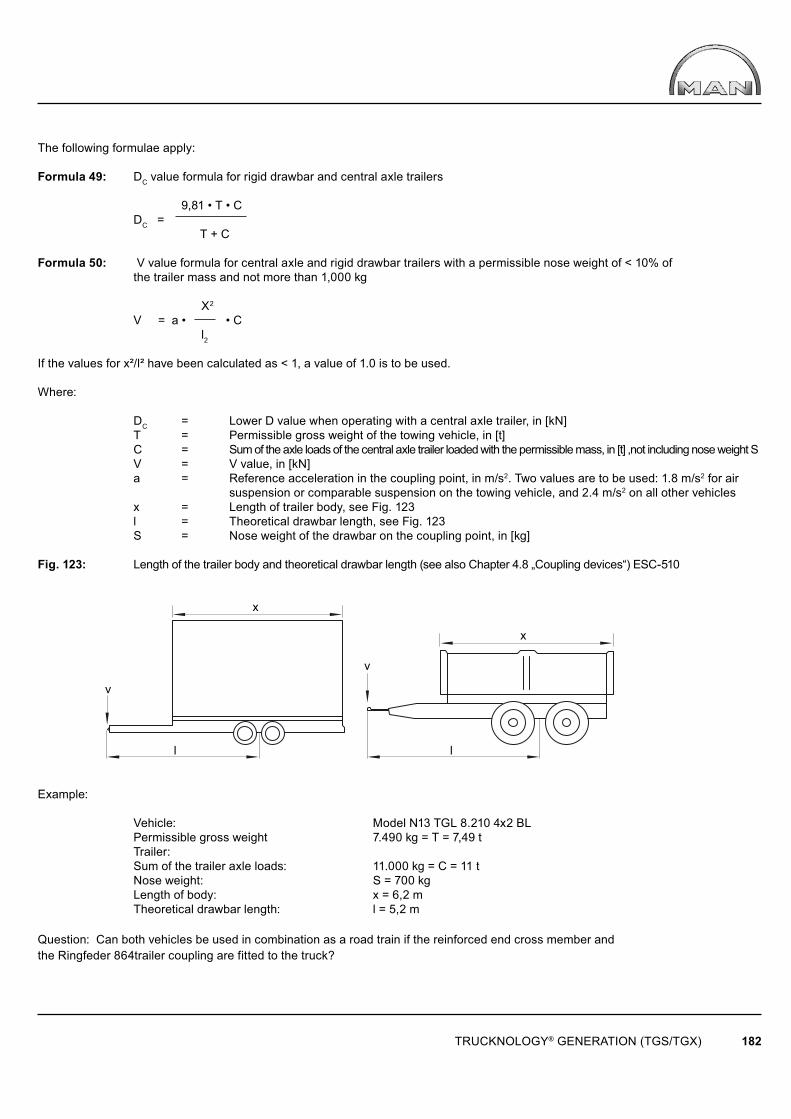
x
v
x
v
l l
TRUCKNOLOGY® GENERATION (TGS/TGX) 182
The following formulae apply:
Formula 49: DC value formula for rigid drawbar and central axle trailers
9,81 • T • C DC = T + C
Formula 50: V value formula for central axle and rigid drawbar trailers with a permissible nose weight of < 10% of the trailer mass and not more than 1,000 kg X2
V = a • • C l2
If the values for x²/l² have been calculated as < 1, a value of 1.0 is to be used.
Where:
DC = Lower D value when operating with a central axle trailer, in [kN] T = Permissible gross weight of the towing vehicle, in [t] C = Sum of the axle loads of the central axle trailer loaded with the permissible mass, in [t] ,not including nose weight S V = V value, in [kN] a = Reference acceleration in the coupling point, in m/s2. Two values are to be used: 1.8 m/s2 for air suspension or comparable suspension on the towing vehicle, and 2.4 m/s2 on all other vehicles x = Length of trailer body, see Fig. 123 l = Theoretical drawbar length, see Fig. 123 S = Nose weight of the drawbar on the coupling point, in [kg]
Fig. 123: Length of the trailer body and theoretical drawbar length (see also Chapter 4.8 „Coupling devices“) ESC-510
Example:
Vehicle: Model N13 TGL 8.210 4x2 BL Permissible gross weight 7.490 kg = T = 7,49 t Trailer: Sum of the trailer axle loads: 11.000 kg = C = 11 t Nose weight: S = 700 kg Length of body: x = 6,2 m Theoretical drawbar length: l = 5,2 m
Question: Can both vehicles be used in combination as a road train if the reinforced end cross member and the Ringfeder 864trailer coupling are fitted to the truck?
TRUCKNOLOGY® GENERATION (TGS/TGX) 183
Solution:
DC value:
9,81 • T • C 9,81 • 7,49 • 11 DC = = T + C 7,49 + 11
DC = 43,7 kN
DC value for end cross member = 64 kN (see Chapter „Coupling devices TG“, Table 2) x2 6,22
= = 1,42 l2 5,22
x2
V = a • C = 1,8 • 1,42 • 11 (1,8 at air suspension rearaxel) l2
V = 28,12 kN
V value for end cross member = 35 kN (see Chapter „Coupling devices TG“, Table 2)
Both vehicles can be combined to form a road train; however, the minimum front axle load of 30% of the respective vehicle weight (including nose weight) must be observed in accordance with the General technical basics in the TGL/TGM Guide to Fitting Bodies.
An unladen truck may pull only an unladen central axle trailer.
9.12.3 Fifth-wheel coupling
The required fi fth-wheel coupling size is determined by the D value. The D value formula for fi fth-wheel couplings is as follows:
Formula 51: D value for fi fth-wheel coupling 0,6 • 9,81 • T • R D = T + R - U
If the D value is known and the permissible gross weight of the semitrailer is sought, the following applies:
Formula 52: Permissible gross weight of the semitrailer
D • (T - U) R = (0,6 • 9.81 • T) - D
If the permissible gross weight of the semitrailer and the D value of the fi fth-wheel coupling are specifi ed, the permissible gross weight of the tractor unit can be calculated with the following formula:
Formula 53: Permissible gross weight of the tractor unit
D • (R - U) T = (0,6 • 9.81 • R) - D
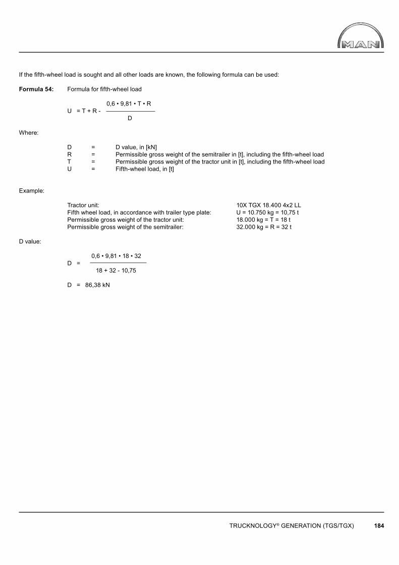
TRUCKNOLOGY® GENERATION (TGS/TGX) 184
If the fi fth-wheel load is sought and all other loads are known, the following formula can be used:
Formula 54: Formula for fi fth-wheel load
0,6 • 9,81 • T • R U = T + R - D
Where:
D = D value, in [kN] R = Permissible gross weight of the semitrailer in [t], including the fi fth-wheel load T = Permissible gross weight of the tractor unit in [t], including the fi fth-wheel load U = Fifth-wheel load, in [t]
Example:
Tractor unit: 10X TGX 18.400 4x2 LL Fifth wheel load, in accordance with trailer type plate: U = 10.750 kg = 10,75 t Permissible gross weight of the tractor unit: 18.000 kg = T = 18 t Permissible gross weight of the semitrailer: 32.000 kg = R = 32 t
D value:
0,6 • 9,81 • 18 • 32 D = 18 + 32 - 10,75 D = 86,38 kN