triz level 3 paper punch
TRANSCRIPT

Rajko Šrimpf, Black Belt Six Sigma, Design for Six Sigma, Applied Reliability, Triz Level 3, March 2014
The DFSS project, designed with the Acclaro DFSS, Minitab, CATIA, TRIZ and Six Sigma
Design of Experiment Axiomatic Design
NEW Rapid 3D prototyping
Trimming
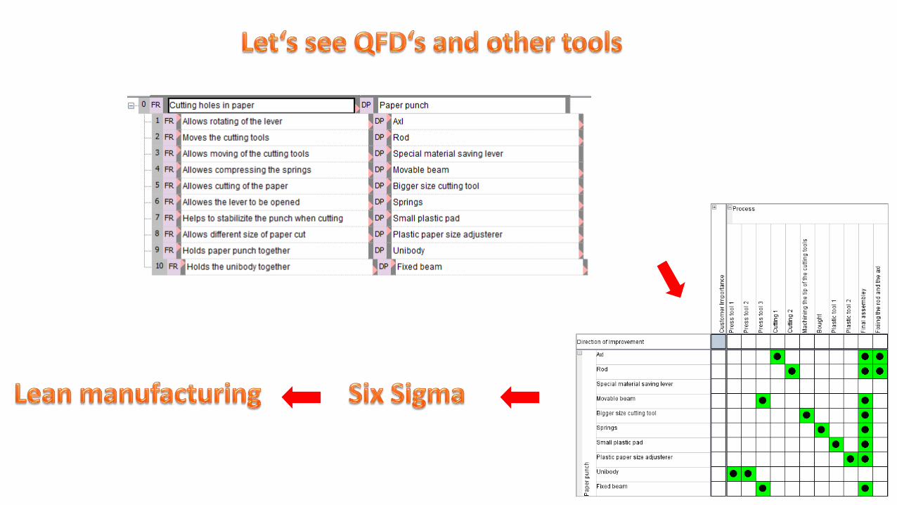
QFD
Risk quad chart
Tree diagram
Flow charter40 invenitve principles
Pareto DFMEA
Trace diagram
ARIZ
NEW Videos of punch while cutting with the springs
NEW Testing 2 types of the punch-modular design
NEW Capability and Design scorecards

IDENTIFY

Project name: Unique paper hole punch
Project overview:
The scope of this project is to design new type of paper hole punch like nothing else in the world market. The new design is going to be lightweight and less expensive than competing product of this type on the market.
Problem statement:
Current puncherers are big and over designed with material because of the strong springs witch are needed to open the puncherer. Our design will save material and production cost. The goal is to use as little production equipment as possible to meet our cost goals.
Customers/Stakeholders:
The new design would appeal to the home and office costumers, who don‘t need a standard big puncherer and can go for a cheap alternative that can still do the job.
Goal of the Project:
To design the cheapest possible hole punch, that can still do the job against competing products. We know that some equipment sells because of design appeal. We are sure that for a non-professional customers all that matters is the cheap price and workable puncherer.
Scope Statement:
I intend to design, and make model with the 3D printing to prove whatever design will come out.
Project financial benefits:
This is so called the project to test DFSS and TRIZ tools, and there is no better way than to learn from a real thing. This is so called TRIZ level 3 certification project.

Maped, the smallest one No name, small
Laco model L350, medium Leitz 5008, medium

Puncher is 3 Stage product
We hit developement limits.Products sell on design apeal and price.Recomendation: COST REDUCTION!But how? Everbody looks almost the same and uses the same solutions.Can we find another?
Some old stuff:

DEFINE

We will use TRIZ tools hereSix Sigma DOE here
Removable Pad
New body of the punch
Device to adjust paper size
Proper angle and size of the lever
Special cutting tools
Category8,9%
32,1%
8,0%
41,1%
9,8%
Pie Chart of CTQ

Red line is a loop!

DESIGN

We will trimm this holders. Somehow we have to add this features to the pad of the puncher.
This is the pad. How on Earth can we add holders to the pad?

We have added all holding function to the Unibody. But how can that be? It has to be revolutionised in every way.

Now we have the pad. What about the stability of the Unibody? We have another TRIZ problem. We will use ARIZ to solve this problem.
Spring and cutting tool holders
Paper removal
Axl holes. To set them at optimum position we will do Design of Experiment
We added grooves for stability

A
B
AB
121086420
Te
rm
Standardized Effect
2,78
A X
B Y
Factor Name
Pareto Chart of the Standardized Effects(response is L, Alpha = 0,05)
Y
X
6050403020100
Te
rm
Standardized Effect
2,57
Pareto Chart of the Standardized Effects(response is Angle, Alpha = 0,05)
X
Y
201816141210
5
4
3
2
1
0
20
30
Angle
14
17
L
Contour Plot of Angle; L
X = 19,7774Y = 2,52626Angle = 25,0147
L = 14,4038
The problem: Where to set axl against the rod?We have x,y coordinates as Factors and two Responses L and Angle!
AngleL
Angle L
Region of the optimal set-ups in white
X
Y
201816141210
5
4
3
2
1
0
>
–
–
–
–
–
–
< 14,2
14,2 14,4
14,4 14,6
14,6 14,8
14,8 15,0
15,0 15,2
15,2 15,4
15,4
L
Contour Plot of L vs Y; X
X
Y
X*Y
Ostalo
CategoryOstalo2,9%
X*Y80,9%
Y8,1%
X8,1%
L distance factors importance
This is very unexpected. I newer had DOE with such a powerful interactions!

Ring compresses the spring
If we use rings only, than we have problem with the stability of the Unibody!
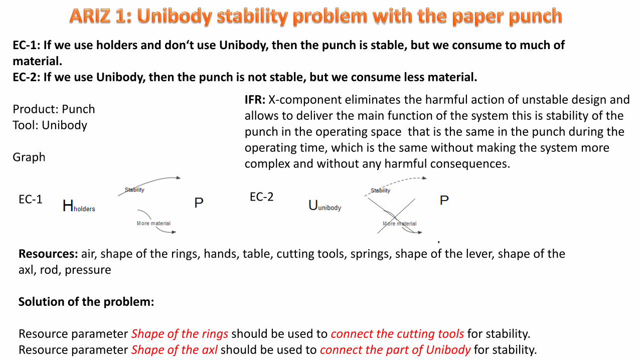
EC-1: If we use holders and don‘t use Unibody, then the punch is stable, but we consume to much of material.EC-2: If we use Unibody, then the punch is not stable, but we consume less material.
Product: PunchTool: Unibody
Graphical representation:
EC-1 EC-2
Resources: air, shape of the rings, hands, table, cutting tools, springs, shape of the lever, shape of the axl, rod, pressure
Solution of the problem:
Resource parameter Shape of the rings should be used to connect the cutting tools for stability.Resource parameter Shape of the axl should be used to connect the part of Unibody for stability.
IFR: X-component eliminates the harmful action of unstable design and allows to deliver the main function of the system this is stability of the punch in the operating space that is the same in the punch during the operating time, which is the same without making the system more complex and without any harmful consequences.
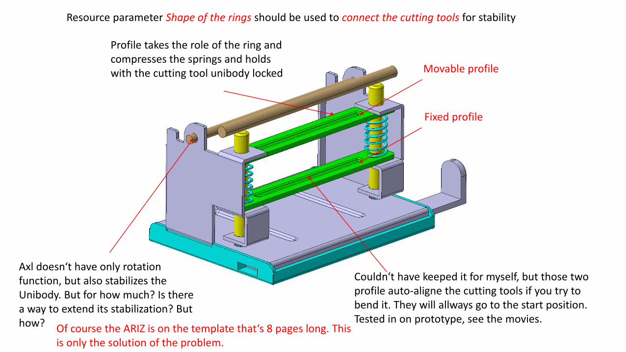
Profile takes the role of the ring and compresses the springs and holds with the cutting tool unibody locked Movable profile
Fixed profile
Axl doesn‘t have only rotation function, but also stabilizes the Unibody. But for how much? Is there a way to extend its stabilization? But how?
Resource parameter Shape of the rings should be used to connect the cutting tools for stability
Couldn‘t have keeped it for myself, but those two profile auto-aligne the cutting tools if you try to bend it. They will allways go to the start position. Tested in on prototype, see the movies.
Of course the ARIZ is on the template that‘s 8 pages long. This is only the solution of the problem.

The axl and O profile locks thight the Unibody.
O profile
Axl
With the lever and O profile in the position, axl slides throught them and then we deform the tips of the axl to prevent falling out of the punch.
Place one object inside of another
We have increased the surface contact between axl + O profile and Unibody.
Additional surface for contact
Resource parameter Shape of the axl should be used to connect the part of Unibody for stability.


Profile adds a lot of stability to the Unibody. You can not bend it inside.
The problem is the bend on the outside like here on the picture. We have solved this problem with the lever, which covers the outside and prevent bending of the Unibody. The tolerance between the Unibody and the lever has to be optimal to allow roation of the lever and not allowing bending unibody on the outside.
This gap is to big in our model. By my calculation it should be about small to prevent from bending and allowing to move the lever easily over the Unibody.
Pressure Tension

While deforming into the groove, material gets harder around it and in it, thus prevents bending.

While deforming into the groove, material gets harder around it and in it, thus prevents bending while applaying force on the lever, hence while cutting the paper.
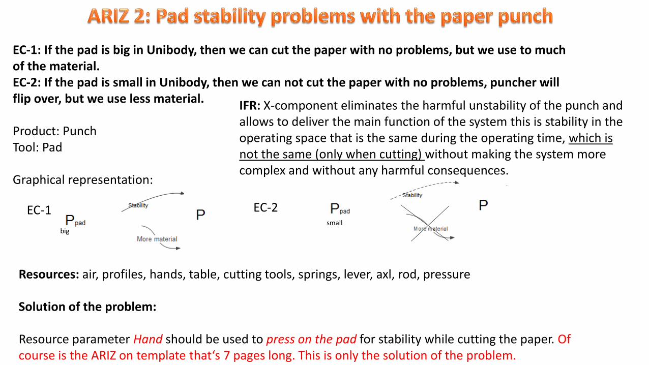
EC-1: If the pad is big in Unibody, then we can cut the paper with no problems, but we use to much of the material.EC-2: If the pad is small in Unibody, then we can not cut the paper with no problems, puncher will flip over, but we use less material.
Product: PunchTool: Pad
Graphical representation:
IFR: X-component eliminates the harmful unstability of the punch and allows to deliver the main function of the system this is stability in the operating space that is the same during the operating time, which is not the same (only when cutting) without making the system more complex and without any harmful consequences.
EC-2
Resources: air, profiles, hands, table, cutting tools, springs, lever, axl, rod, pressure
Solution of the problem:
Resource parameter Hand should be used to press on the pad for stability while cutting the paper. Of course is the ARIZ on template that‘s 7 pages long. This is only the solution of the problem.
EC-1
bigsmall

With one hand we press on the backside of the pad
With second hand we press on the lever of the pad to cut the paper
Since we have separation in time we look for the principles that solve this problem. The principle 9: Preliminary anti-action was used. If it is necessary to perform an action with both harmul and useful effects,
this action should be replaced with anti-action to control harmful effects.
Inventive principles for seperation in time:Principle 9: Preliminary anti-actionPrinciple 10: Preliminary actionPrinciple 11: In-advance „cushioning“Principle 15: DynamicsPrinciple 34: Discarding and recovering
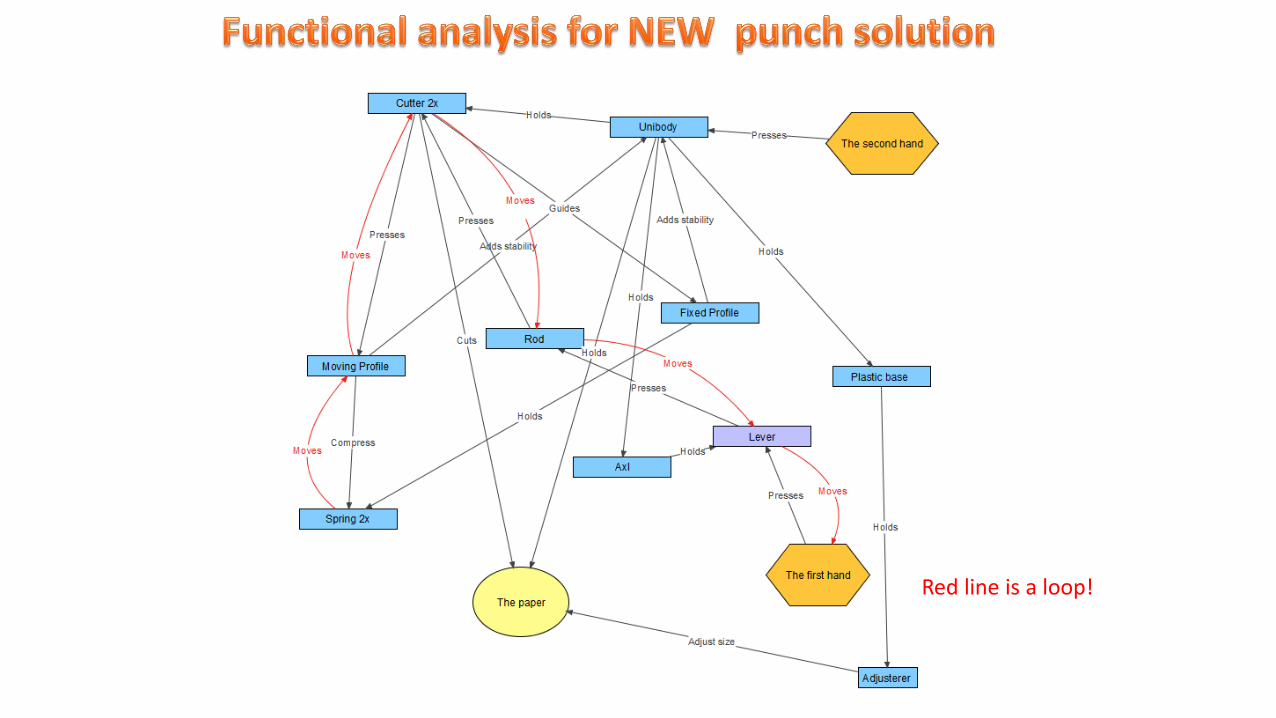
Red line is a loop!

This rotation actually allowes to use the second hand!!!


With type 2 and 3 pad we end up with more paper clips space and allow the Unobody main pocket to be deeper thus preventing ther Unibody to bend in any way while cutting.
Space for the paper clips
Adds stability while cutting
Type 1 pad
Type 2 pad optimized with increased space for paper clips
Type 3 pad optimized with increased space for paper clips without one support

First model Added grooves Added chamfer Added pocket
Added big pocket
Added bend of material for stability
Increased size of the pocket
Bend removed
Pocket is deeper

I have made a simplification of the steps needed. If it is necesary we can add more steps espeacially at cutting. This is only represantation, actual space between stations might vary, let‘s say they are probably bigger. I think we have to add calibration step for bend parts of the product . What is Axiomatic Design saying about the complexity of the steps in the press tool?
If there is a problem with this pocket when cutting we could me it a bit smaller! Like this.
Principle 10: Preliminary action, we drew pocket deep before cutting.
We need to separate steps so there needs to be cutting tool or we cut after the pocket!
Cutting holes!

Only the lever is different between this two types of products. A modular design, who tought about that in this industry?
Type 1: Small lever
Type 2: Big lever


Axiom 1: The Independnce Axiom:Maintain the independance of the functional requirements.
Axiom 2: The Information Axiom:Minimize the information contect in a design.
Uncoupled design
Decoupled design
Coupled design
Category
Coupled design56,3%
Decoupled design37,5%
Uncoupled design6,3%
Probability of design
We have decoupled design, so it is than more likely that we will achive Six Sigma quality level. So, I would be happy even with the 5 Sigma level.
So 56,3 % of all designs are coupled design? Is it just me to see it that way, or this is a major problem for manufacturers?


6,83 is left for the hand that does 26 33,29 is left for the hand that does 26

- Cutting competitive amount of paper
- Paper size adjusterer
- Less expensive, cos‘ less machinery and people manufacturing it
- More portable, less weight (big punch)
- Design appeal
- Have to use both hands only in the big one- Less capacity for paper clips, oh, this is not a
problem as I see it. Who colects clips anyway?

Item Function Failure Mode Failure Effect
Seve
rity
Potential Failure Cause Preventive Action
Occ
urr
ence
Detection Action
Det
ecti
on
RP
N
Cutting tool Cutting Broken tool Not cutting properlly 1 Bad material Proper material 1 Visual 1 1
Profile Compressing the spring & stability Broken Not compressing the spring 2 Bad material Proper material 2 Not working 1 4
Spring To lift the tool Broken Not working 1 Bad material Porper material 1 Not working 1 1
Profile Stability Bend Failled stability of the unibody 2 Bad material Porper material 2 Not cutting 1 4
Unibody Holding the cutter together Bend unibody Not cutting properlly 3 Failled profile Quality sheet metal tool 2 Not working 1 6
Lever Axial movement Bend Not working 1 Failed Perpendicularity Quality sheet metal tool 1 Not working 2 2
Base Holding the Unibody Doesn't fit Can not attach to unibody 1 Bad plastic tool Adjust tool properlly 1 Doesnt' fit 1 1
P. adjusterer Adjusting to the paper size Doesn't fit Can not adjust paper size 2 Bad plastic tool Adjust tool properlly 1 Doesnt' fit 1 2
Axl Rotating the lever Broken Not working 1 Bad plastic tool Adjust tool properlly 1 Doesnt' fit 2 2
O profile Adss stability Broken No stability of Unibody 2 Bad tolerance Proper tolerance 1 Doesnt' fit 1 2
RPN 18 6 2 2 2 2 1 1
Percent 4,032,0 24,0 8,0 8,0 8,0 8,0 4,0 4,0
Cum % 100,032,0 56,0 64,0 72,0 80,0 88,0 92,0 96,0
Item
Othe
r
Cutting
tool
Base
P. adjus
tere
r
O profile
Leve
rAx
l
Unibod
y
Profile
25
20
15
10
5
0
100
80
60
40
20
0
RP
N
Pe
rce
nt
Pareto Chart of Item
OPTIMIZE

3D RAPID PROTOTYPING


So, here are the final dimensions of the holes. With the 3D print they will vary. Will do scorecrads for each of them, but only for 4 or 5, cos I will not produce then just makeing the prototypes. Of course, if you are reading this you might be Six Sigma expert and understand the importance of low variation of the dimensions of the parts to be assembled togehter.

Since I am gonna print many cutting tools for tests, I will make capability analysis in Minitab to see how stable is the printed process for sample size.

I had two suppliers for this prototype. To bad in Slovenia they just couldn‘t make them. Very disapointing to say at least. I have choosen 3DShub and have found a supplier in Austria. He did a very nice job. The pad rubber was printend in Belgium. So I have international suppliers. This prototype is partly functional, I still have to make rods, profiles, cutting tools and some cheap springs. I bet it will cut one sheet, just to show that the design works. Black rubber looks good, will use it in the future.


Kinematics is now fully optimizied, even the pitch and the hight of the springs are now adjusted to the rotation of the leverand moving of the cutting tools. It took some time, to bad you can not do it with the one update in Catia, but you have to upadate the model twice. No exotic kinematics add-ons were used.
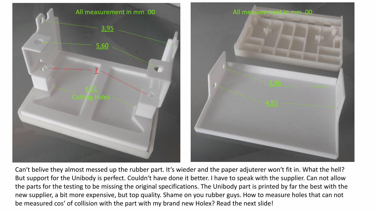
Can‘t belive they almost messed up the rubber part. It‘s wieder and the paper adjuterer won‘t fit in. What the hell? But support for the Unibody is perfect. Couldn‘t have done it better. I have to speak with the supplier. Can not allow the parts for the testing to be missing the original specifications. The Unibody part is printed by far the best with the new supplier, a bit more expensive, but top quality. Shame on you rubber guys. How to measure holes that can not be measured cos‘ of collision with the part with my brand new Holex? Read the next slide!
3,95
5,60
4,61Cutting holes
All measurement in mm .00
4,95
3,96
All measurement in mm .00
?

So, Gage R&R is marginal, study is 26,35% variance for the meausering system. Variance for the tolerance is 16,87 %. It‘s notquite the best study we have ever did, but I am now confident that the meausering parts for system capability will be still tolerable. Still Holex brand digital caliper si good, but Mitutoyos are the best, but still the 0.001 tolerance on sintering parts?
Part-to-PartReprodRepeatGage R&R
100
50
0
Perc
ent
% Contribution
% Study Var
% Tolerance
10 9 8 7 6 5 4 3 2 110 9 8 7 6 5 4 3 2 110 9 8 7 6 5 4 3 2 1
0,02
0,01
0,00
Part
Sam
ple
Range
_R=0,00833
UCL=0,02145
LCL=0
A B C
10 9 8 7 6 5 4 3 2 110 9 8 7 6 5 4 3 2 110 9 8 7 6 5 4 3 2 1
4,48
4,44
4,40
Part
Sam
ple
Mean
UCL=4,45030
LCL=4,43325
A B C
__X=4,44178
10987654321
4,48
4,44
4,40
Part
CBA
4,48
4,44
4,40
Operator
10987654321
4,48
4,44
4,40
Part
Avera
ge
A
B
C
Operator
Gage name: Gage diameter of the cutting tools
Reported by : Rajko Š rimpf
Tolerance:
Misc:
Components of Variation
R Chart by Operator
Xbar Chart by Operator
Meauserument by Part
Meauserument by Operator
Part * Operator Interaction
Gage R&R (ANOVA) for Meauserument
4,475
4,450
4,425
4,400
4,475
4,450
4,425
4,400
1
Operator
Me
au
se
rum
en
t
Mean
2 3 4 5
6 7 8 9 10
Mean
A
B
C
O perator
Gage name:
Date of study :
Reported by :
Tolerance:
Misc:
Panel variable: Part
Gage Run Chart of Meauserument by Part, Operator
You se small variation between mearusement? I bet you won‘t belive the scale. It‘s 0.01 mm. Belive it or not. We did it. Took use 3 trials for Gage from 90 % to 50 % and now 26,35%. This is as good as it gets on solid sintering parts.
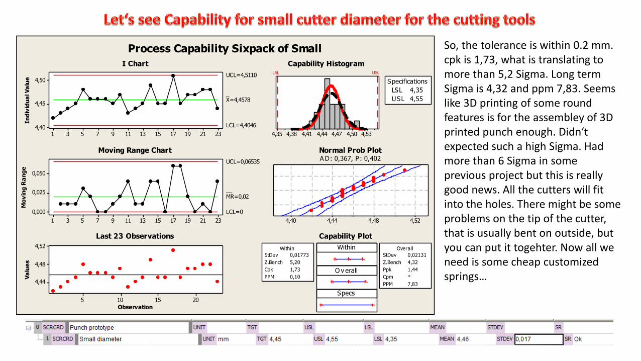
So, the tolerance is within 0.2 mm. cpk is 1,73, what is translating to more than 5,2 Sigma. Long term Sigma is 4,32 and ppm 7,83. Seems like 3D printing of some round features is for the assembley of 3D printed punch enough. Didn‘t expected such a high Sigma. Had more than 6 Sigma in some previous project but this is really good news. All the cutters will fit into the holes. There might be some problems on the tip of the cutter, that is usually bent on outside, but you can put it togehter. Now all we need is some cheap customized springs…
2321191715131197531
4,50
4,45
4,40
In
div
idu
al V
alu
e
_X=4,4578
UCL=4,5110
LCL=4,4046
2321191715131197531
0,050
0,025
0,000
Mo
vin
g R
an
ge
__MR=0,02
UCL=0,06535
LCL=0
2015105
4,52
4,48
4,44
Observation
Va
lue
s
4,534,504,474,444,414,384,35
LSL USL
LSL 4,35
USL 4,55
Specifications
4,524,484,444,40
Within
O v erall
Specs
StDev 0,01773
Z.Bench 5,20
Cpk 1,73
PPM 0,10
Within
StDev 0,02131
Z.Bench 4,32
Ppk 1,44
Cpm *
PPM 7,83
Overall
Process Capability Sixpack of Small
I Chart
Moving Range Chart
Last 23 Observations
Capability Histogram
Normal Prob PlotA D: 0,367, P: 0,402
Capability Plot

Sigma is not as high as on the small diameter cos‘ the lower tolerance is out but it still long term Sigma is 3.73 and Ppk is 1.24, ppm is 95,24. This was in the line of expectation. The process is slightly moved to the left. What I wanted to show is how Six Sigma is important on tolerance calculations. Every Design for Six Sigma project should have many Six Sigma projects and of course be finished with the Applied Reliability and Lean for manufacturing. The p value is on the limit, but it‘s above 0.05, so I did the capability.
2321191715131197531
5,52
5,46
5,40
In
div
idu
al V
alu
e
_X=5,4261
UCL=5,4986
LCL=5,3536
2321191715131197531
0,10
0,05
0,00
Mo
vin
g R
an
ge
__MR=0,0273
UCL=0,0891
LCL=0
2015105
5,450
5,425
5,400
Observation
Va
lue
s
5,555,525,495,465,435,405,37
LSL USL
LSL 5,35
USL 5,55
Specifications
5,505,455,405,35
Within
O v erall
Specs
StDev 0,02418
Z.Bench 3,15
Cpk 1,05
PPM 825,05
Within
StDev 0,02039
Z.Bench 3,73
Ppk 1,24
Cpm *
PPM 95,24
Overall
Process Capability Sixpack of Big
I Chart
Moving Range Chart
Last 23 Observations
Capability Histogram
Normal Prob PlotA D: 0,724, P: 0,051
Capability Plot

I did the prototype with the springs. The design works perfectly, it even cuts the paper with the sintering cutting tools. Who knew? It just works if you set your mind, time and limited resources to good use. It‘s like 6 Sigma. Did it allways with no resources available and was sucessful most of the time.

So punch is working, little bends, but with the sheet metal they will be faded away… click on video!

Punching the holes…. Have to take into consideration that I am useing not metal cutters, but sintering, which are not that sharp.

Punching the holes with the big one...

VALIDATE


And of course, not for this project but for solving ARIZ problem twice, I was rewarded with the TRIZ LVL 3 certificate!
I couldn‘t have helped myself for not posting TRIZ LVL 1 and 2 certificates also.

And I am also in the data-bank on www.matriz.org