triz journal october 2000 issue - metodolog.ru · triz journal october 2000 issue ... 2. on the...
TRANSCRIPT
For the first time, this entire issue can be viewed and printed in a single PDF document.
TRIZ Journal October 2000 Issue
1. Getting TRIZ Accepted in a Very Busy World By: Jack Hipple
2. On the History of Separation Principles By: Y. B. Karasik
3. Intuitive Design Method (IDM), A New Approach on Design Methods Integration By: Denis CAVALLUCCI, Philippe LUTZ
4. Containment ring problem (Impeller burst) IWB Case study By: Alla Zusman
5. Enhancing Robust Design with the Aid of TRIZ and Axiomatic Design (Part I) By: Matthew Hu, Kai Yang, Shin Taguchi
6. The Conceptual Design Of A Fast Clasping Mechanism Based On Function Means Tree And TRIZ By: Tan Runhua
7. The "Sabotage Model" or how to find the cause to difficult and mysterious problems: The case of Recovery Boiler compound tube corrosion By: Pentti Soderlin
-2000 The TRIZ Institute http://www.triz-journal.com
All Rights Reserved.
GETTING TRIZ ACCEPTED IN A VERY BUSY WORLD
Jack Hipple Senior Consultant Idea Connections
Urbana, IL 217-344-2571
217-344-2572(FAX) [email protected]
TRIZ and its many embodiments in various consulting and software programs is a powerful addition to set of problem solving tools available to engineers, human resource managers, organizational development personnel, and strategic planners. However, as many suppliers of software, training, and consulting services have found, it is not necessarily easy to gain acceptance of a new tool no matter how good we in the TRIZ community think it is. This presentation will review the barriers to acceptance and suggestions on ways to overcome them.
As everyone who uses the TRIZ methodology, its software embodiments, and its various enhancements knows, it is a powerful tool for problem analysis and solution. Many TRIZ problem solvers have seen TRIZ techniques solve problems unsolvable by other methods and teams of people working for long periods of time. If this is true, why has TRIZ not taken off in the same way as other widely accepted industrial problem solving processes and tools? Or is it that we are simply impatient and its adoption is on its normal course? This author believes the experiences in the market place would suggest that a combination of these two issues is responsible. If we do not take the time to understand and these issues, the TRIZ community will continue to be frustrated in its attempts to commercialize a problem solving process which is known to be an extremely valuable tool. Though the comments in this paper are generic in nature and this author believes they apply to any form of the TRIZ methodology, the experiences related in this paper have come primarily from running 3-day problem solving sessions with Ideation TRIZ and the use of the Innovation Workbench® software. These are the issues and factors that must be considered in the process of getting TRIZ accepted by its potential customers: 1. TRIZ must be considered as a new technology. In the sense that any new
technology presents a new way of solving problems, it is no less difficult to get people to accept TRIZ than it was the copier machine, desktop computers, cell phones, or other problem solving techniques such as QFD, Taguchi methods, Six Hats® and Lateral Thinking®, or Creative Problem Solving. If TRIZ advocates
assume that there is something magical or different about TRIZ that makes it easier to accept and adopt, we are deceiving ourselves.
2. Any new technology has competition. To assume that any competition is going to
instantly get out of the way and disappear is naïve. In the case of new thinking and problem solving methodologies, the resistance is not always in the form of price-cutting, hiring away key people, or the numerous other activities that are sometimes seen in product competition. However, the investment already made by organizations and individuals in those organizations in other tools can be a significant barrier.
3. Everyone’s plate is very full and nearly everyone is overcommitted in time and
resources. Learning anything new, whether it is TRIZ or any other new tool, takes time. To ignore this simple fact and not have the patience to deal with it will lead to frustration and commercial failure.
4. New technology adoption varies with organizations and within organizations.
There have always been early adapters and late adapters in any industry, and in any technology area. It is important to figure out who these people are and work with them to accelerate the adaption process. The factors mentioned above are still issues, but potentially less so. Technology adaption within organizations also varies greatly. Much less frequently than 20 years ago, a senior leader in an organization has a clear vision and decrees that a certain process and tool will be used. This does not guarantee ultimate success, but it does get things started. A far more likely scenario in today’s business world is that general interest from a senior leader generates a search to find a volunteer and champion who will try the new process and tool. Then the experience is shared and slowly pollinates within the organization.
5. Learning and problem solving processes vary a great deal by individuals and by
organizations. It is important to know these different styles and how they can affect the style in which TRIZ training and problem solving should be done.
Let’s take each of these issues and barriers one at a time and discuss them. TRIZ as a New Technology People have been solving problems for thousands of years with many different kinds of tools, processes, and techniques. It is hard for many people today to believe that problems were solved without computers, but they were as little as 40 years ago. Most engineers and scientist have heard the story of the first market projections for computer printers by HP as being no more than 500 per year and carbon paper would live forever (has anyone even seen a sample of carbon paper lately?). However, these transitions did not occur instantaneously and without pain, despite the fact that in hindsight they were tremendous inventions that we now find we must have.

In this particular case, what is it about TRIZ that is different? That might make it difficult to accept? Let’s look at the fundamentals of the methodology. First there is the concept of Ideality or Idea Final Result. Only children can think this way easily. By the time engineers have graduated and faced many jaw boning contradictions that they could not resolve, the concept that there is value in dreaming and imagining a contradiction free situation is very difficult, and to many, impractical and useless. The use of compromise as a design philosophy is very strong! What can help here is examples and illustration of where compromise has been overcome with TRIZ. Many corporate clients obviously require confidentiality and these examples are hard to come by. One role for the Altshuller Institute might be as a “storage” for examples which clients have allowed to be shared. Most design engineers are, by nature and by training, analogous thinkers, and anything that provides examples helps tremendously. Case studies are a key to education and understanding, especially case studies form the real world that our customers live in. The second step in this process of acceptance is to get people to understand that the need for compromise is driven by the existence of contradictions. Most western engineers have lived with contradictions for years and it is their job security! The fact that resolving a contradiction might eliminate a complicated design in which an engineer has invested hundreds of hours of efforts can actually seem to be job threatening rather than being a productivity enhancement. TRIZ session leaders need to think ahead to a typical TRIZ problem solving session, that lasts only 3 days, generating a breakthrough solution to a problem that had generated a less than satisfactory solution and for which an organization spent thousands of dollars and months of time. All TRIZ problem solvers have seen TRIZ professionals salivate and run toward contradictions because they know that is where the opportunity is. We must recognize that most of our clients, seeing a contradiction, see bottles of extra-strength pain relief pills. An effective technique here is to borrow from other creative process techniques and get people to close their eyes and imagine the ideal world without compromise. This kind of group thinking process is used regularly in other types of creative sessions. After this exercise, one can encourage the engineers and problem owners to imagine what their life would be like without unresolved contradictions and design conflicts. Getting people to draw pictures of ideality is also an effective technique because it can start the journey. Another incentive is to get the engineers to think about what they could be doing instead of what they are currently doing. Would they rather be working on the next generation of a product or system, or fixing all the problems in the current design? Would they rather be scaling up a new product or process, or being called out on the midnight shift to fix something that never quite works right? Positive incentives work far better than fear of job security in motivating people to try new things, whether it is TRIZ or anything else. Consider the Competition We have all seen many pictures of “S” curves as representations of systems’ evolution, growth, and eventual decline. Any mature industry or technology that is not actively trying to reinvent itself fights back with a vengeance. In the case of problem solving techniques, the resistance doesn’t always come in the form of outright negativity, but from the simple fact that thousands of dollars may have been spent training and

institutionalizing a process. And it helps to remember that these processes HAVE solved problems and have a positive reputation. These existing problem-solving processes have, in large corporations, utilized sometimes tens or hundreds of trainers and thousands of dollars in training materials. Personal credibilities are frequently at risk, especially when a senior executive has committed to a program. In the case of few or no existing problem solving tools (a rare case), the challenge is far easier, but the demonstration of the uniqueness of the tool is still required. The amount of inertia to overcome is also directly proportional to the amount of money the potential user is expected to invest to try the new tool. One of the fatal mistakes that can be made is to attack these existing tools as inferior or useless. It is far better to take the time to understand how the existing tool is being used and then figure out how to complement and improve it. Offering to run an inexpensive experiment for a potential user can also help to overcome resistance. Collaboration rather than confrontation should be the rule. Everyone attempting to sell TRIZ to a potential user needs to be able to clearly state how TRIZ can improve and complement QFD, Creative Problem Solving, Six Hats®, Lateral Thinking®, Taguchi methods, Six Sigma, and other tools. There is no organization that is not using some or all of these tools. They will not adopt TRIZ or any of its software embodiments without understanding how it will complement or cost-effectively replace them. Some TRIZ advocates draw a large TRIZ circle, and all other problem solving tools around it, as if it were the center of the universe. This is not the way to get TRIZ accepted. TRIZ advocates must recognize that there is value in many of the tools and identifying the collaborative and complimentary space is the best way to start. The Plate is Full Many times a potential user telling TRIZ advocates that their commitments are overwhelming, and that they have no time to evaluate TRIZ, is discouraging. Sometimes advocates hear about the new product launches that are underway. And other times they hear about the massive investment being made in another problem solving tool (Six Sigma is the latest), which brings up the competitive issue discussed previously. In this case, there are two approaches. Advocates can put potential users in their tickler file and follow up when appropriate. This is frequently the right approach, depending upon the situation. The second is to try to figure out how TRIZ can help make the plate less full. This requires more patience than most advocates normally have. It requires spending enough time with the customer to understand what is overwhelming them and how they can be helped. Frequently, getting the potential TRIZ users to express their frustrations in terms of contradictions is a good place to start. Then the basic concept of TRIZ problem solving can be brought up for discussion. One of the other commentaries that is heard is that “we don’t need any more ideas, we need to implement the ones we have.” TRIZ practitioners know that the basic problem
solving principles they use can be used in either situation, but they too often narrow the application of the principles. One of the most gratifying things that this user has seen in the past few years is the application of the TRIZ principles to organizational and management issues. The use of the Ideation TRIZ Problem Formulator® has been especially useful in this regard. All people who have run TRIZ problem-solving sessions know that the discipline that they use in TRIZ to properly define the problem is the most useful and important part of the methodology. They constantly see new awareness develop after the correct kinds of problem definition questions have been asked. The truly cost-impacting aspect of TRIZ can be in this phase. The amount of time and money that organizations spend on solving the wrong or poorly defined problem is incredible. This is the aspect of TRIZ that is most marketable to groups with full plates, because every poorly defined problem is spending valuable resources that can be better used elsewhere. Technology Adoption An organization adopting TRIZ is no different from an organization adopting bar coding or laser video inspection. It is something different that changes the status quo. There are whole companies and organizations that thrive on being the first to adapt new technologies and leading their peers. Others prefer to see others take the risk and invest later. They are taking the chance that the expensive learning is more of a risk than the waiting. TRIZ advocates must recognize that the use of TRIZ is a paradigm shift in how problems are both analyzed and solved, and that everyone is not prepared to be a paradigm shifter. It is usually easy to tell the difference in conversations with representatives of organizations, or by reading the literature, patent filings, talking to other consultants, etc. Pairing up with rapid technology adopters is highly preferred. If one looks at the adoption of certain types of quality and manufacturing processes, it is seen that the top of the food chain drives them. If someone is a supplier to the Ford Motor Co., and they do not choose to follow Ford’s supplier requirements, they will not be a Ford supplier for long. Using TRIZ in joint problem solving and product design sessions with supplier and customers in the room together can be very powerful. This obviously requires a co-operative, trusting relationship between the parties involved. The joint use of TRIZ could greatly accelerate the adoption of TRIZ in a particular industry, especially if the results were published. Recognition of Different Learning Styles In addition to differences in organizational adoption, there are distinct differences in how individuals learn new things. At Idea Connections, we have begun to use Michael Kirton’s KAI assessment tool as part of some of our Ideation TRIZ sessions. This is a globally validated psychological assessment tool that measures the style in which people
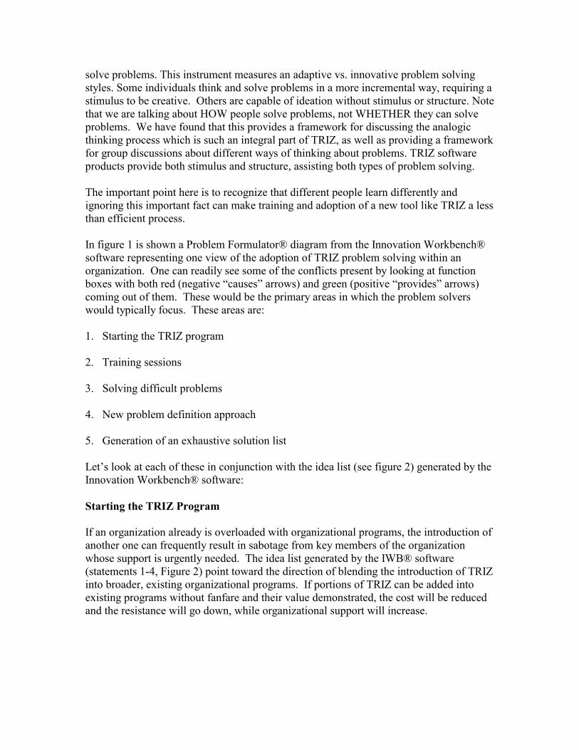
solve problems. This instrument measures an adaptive vs. innovative problem solving styles. Some individuals think and solve problems in a more incremental way, requiring a stimulus to be creative. Others are capable of ideation without stimulus or structure. Note that we are talking about HOW people solve problems, not WHETHER they can solve problems. We have found that this provides a framework for discussing the analogic thinking process which is such an integral part of TRIZ, as well as providing a framework for group discussions about different ways of thinking about problems. TRIZ software products provide both stimulus and structure, assisting both types of problem solving. The important point here is to recognize that different people learn differently and ignoring this important fact can make training and adoption of a new tool like TRIZ a less than efficient process. In figure 1 is shown a Problem Formulator® diagram from the Innovation Workbench® software representing one view of the adoption of TRIZ problem solving within an organization. One can readily see some of the conflicts present by looking at function boxes with both red (negative “causes” arrows) and green (positive “provides” arrows) coming out of them. These would be the primary areas in which the problem solvers would typically focus. These areas are: 1. Starting the TRIZ program 2. Training sessions 3. Solving difficult problems 4. New problem definition approach 5. Generation of an exhaustive solution list Let’s look at each of these in conjunction with the idea list (see figure 2) generated by the Innovation Workbench® software: Starting the TRIZ Program If an organization already is overloaded with organizational programs, the introduction of another one can frequently result in sabotage from key members of the organization whose support is urgently needed. The idea list generated by the IWB® software (statements 1-4, Figure 2) point toward the direction of blending the introduction of TRIZ into broader, existing organizational programs. If portions of TRIZ can be added into existing programs without fanfare and their value demonstrated, the cost will be reduced and the resistance will go down, while organizational support will increase.
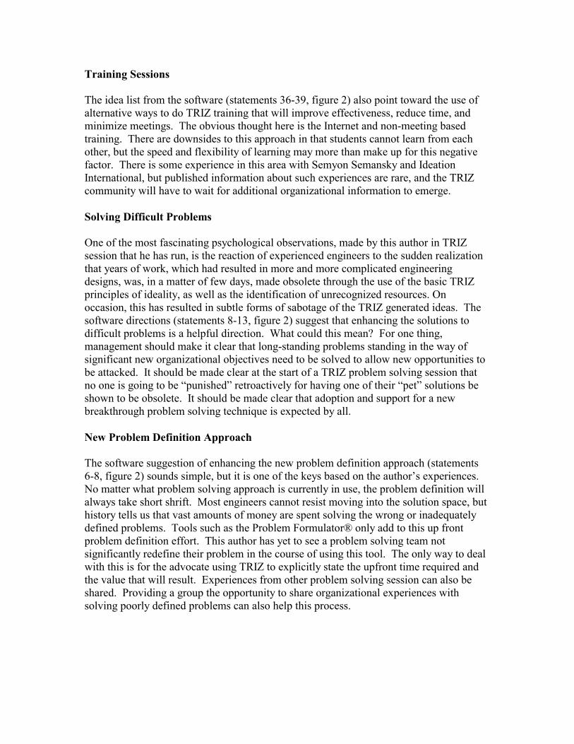
Training Sessions The idea list from the software (statements 36-39, figure 2) also point toward the use of alternative ways to do TRIZ training that will improve effectiveness, reduce time, and minimize meetings. The obvious thought here is the Internet and non-meeting based training. There are downsides to this approach in that students cannot learn from each other, but the speed and flexibility of learning may more than make up for this negative factor. There is some experience in this area with Semyon Semansky and Ideation International, but published information about such experiences are rare, and the TRIZ community will have to wait for additional organizational information to emerge. Solving Difficult Problems One of the most fascinating psychological observations, made by this author in TRIZ session that he has run, is the reaction of experienced engineers to the sudden realization that years of work, which had resulted in more and more complicated engineering designs, was, in a matter of few days, made obsolete through the use of the basic TRIZ principles of ideality, as well as the identification of unrecognized resources. On occasion, this has resulted in subtle forms of sabotage of the TRIZ generated ideas. The software directions (statements 8-13, figure 2) suggest that enhancing the solutions to difficult problems is a helpful direction. What could this mean? For one thing, management should make it clear that long-standing problems standing in the way of significant new organizational objectives need to be solved to allow new opportunities to be attacked. It should be made clear at the start of a TRIZ problem solving session that no one is going to be “punished” retroactively for having one of their “pet” solutions be shown to be obsolete. It should be made clear that adoption and support for a new breakthrough problem solving technique is expected by all. New Problem Definition Approach The software suggestion of enhancing the new problem definition approach (statements 6-8, figure 2) sounds simple, but it is one of the keys based on the author’s experiences. No matter what problem solving approach is currently in use, the problem definition will always take short shrift. Most engineers cannot resist moving into the solution space, but history tells us that vast amounts of money are spent solving the wrong or inadequately defined problems. Tools such as the Problem Formulator® only add to this up front problem definition effort. This author has yet to see a problem solving team not significantly redefine their problem in the course of using this tool. The only way to deal with this is for the advocate using TRIZ to explicitly state the upfront time required and the value that will result. Experiences from other problem solving session can also be shared. Providing a group the opportunity to share organizational experiences with solving poorly defined problems can also help this process.

Exhaustive Solution Set List One of the real assets of the TRIZ problem solving process is the generation of a near-exhaustive solution set list. TRIZ practitioners recognize this as a real positive aspect of the methodology, but many problem solving groups are overwhelmed by the output of the process, especially with the use of software such as the Innovation Workbench®. In working with a group, it is important for the facilitator to make the point that the best solution can only be obtained by making sure that all solutions have been considered. Management can reinforce the point that committing millions of dollars to new projects can only be done in confidence when all options have been considered. The other point that can be made in the direction of “enhancing the exhaustive solution list” is to recognize the value in such a list from the standpoint in intellectual property strategy. Even if the organization cannot afford or chooses not to pursue all directions, patent claims can be filed which may result in licensing revenue. The handling of large idea lists can also he enhanced by sharing the evaluation task among several individuals and groups. This not only spreads the workload, but also provides the opportunity to obtain divergent idea inputs. Directions relating to this area are in statements 32-35 in figure 2. In summary, we must consider a large number of external factors and issues when deciding how to approach different kinds of customers with out TRIZ tools. Tailoring our approach and how we use our various tools can be the key to successful implementation and sale of TRIZ software and consulting.
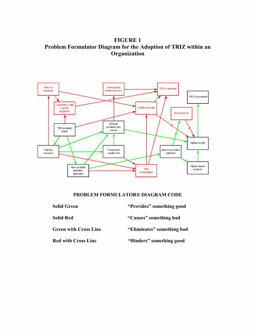
FIGURE 1
Problem Formulator Diagram for the Adoption of TRIZ within an Organization
PROBLEM FORMULATOR® DIAGRAM CODE
Solid Green “Provides” something good
Solid Red “Causes” something bad
Green with Cross Line “Eliminates” something bad
Red with Cross Line “Hinders” something good

FIGURE 2
IDEA LIST DERIVED FROM THE INNOVATION WORKBENCH® PROBLEM FORMULATOR® DIAGRAM IN FIGURE 1
1. Find an alternative way to obtain [the] (TRIZ program starts). 2. Find a way to enhance [the] (TRIZ program starts). 3. Find a way to resolve the contradiction: [the] (TRIZ program starts) should exist to obtain [the] (New problem definition approach) and (Training sessions), and should not exist in order to avoid [the] (Competition with current programs) and (Additional costs). 4. Find a way to do without [the] (TRIZ program starts). 5. Find a way to eliminate, reduce or prevent [the] (Competition with current programs). 6.Find an alternative way to obtain [the] (New problem definition approach). 7. Find a way to enhance [the] (New problem definition approach). 8. Find a way to resolve the contradiction: [the] (New problem definition approach) should exist to obtain [the] (Improved project selection) and (Difficult problems are solved), and should not exist in order to avoid [the] (Time consumption). 9. Find a way to do without [the] (New problem definition approach). 10. Find an alternative way to obtain [the] (Difficult problems are solved). 11. Find a way to enhance [the] (Difficult problems are solved). 12. Find a way to resolve the contradiction: [the] (Difficult problems are solved) should exist to obtain [the] (Higher profits), and should not exist in order to avoid [the] (Professional embarrassment). 13. Find a way to do without [the] (Difficult problems are solved). 14. Find an alternative way to obtain [the] (Improved project selection). 15. Find a way to enhance [the] (Improved project selection). 16. Find a way to do without [the] (Improved project selection). 17. Find an alternative way to obtain [the] (Higher impact projects). 18. Find a way to enhance [the] (Higher impact projects). 19. Find a way to do without [the] (Higher impact projects). 20. Find an alternative way to obtain [the] (Higher profits). 21. Find a way to enhance [the] (Higher profits). 22. Find a way to protect [the] (Higher profits) from the harmful influence of [the] (Additional costs) and (Poor projects).
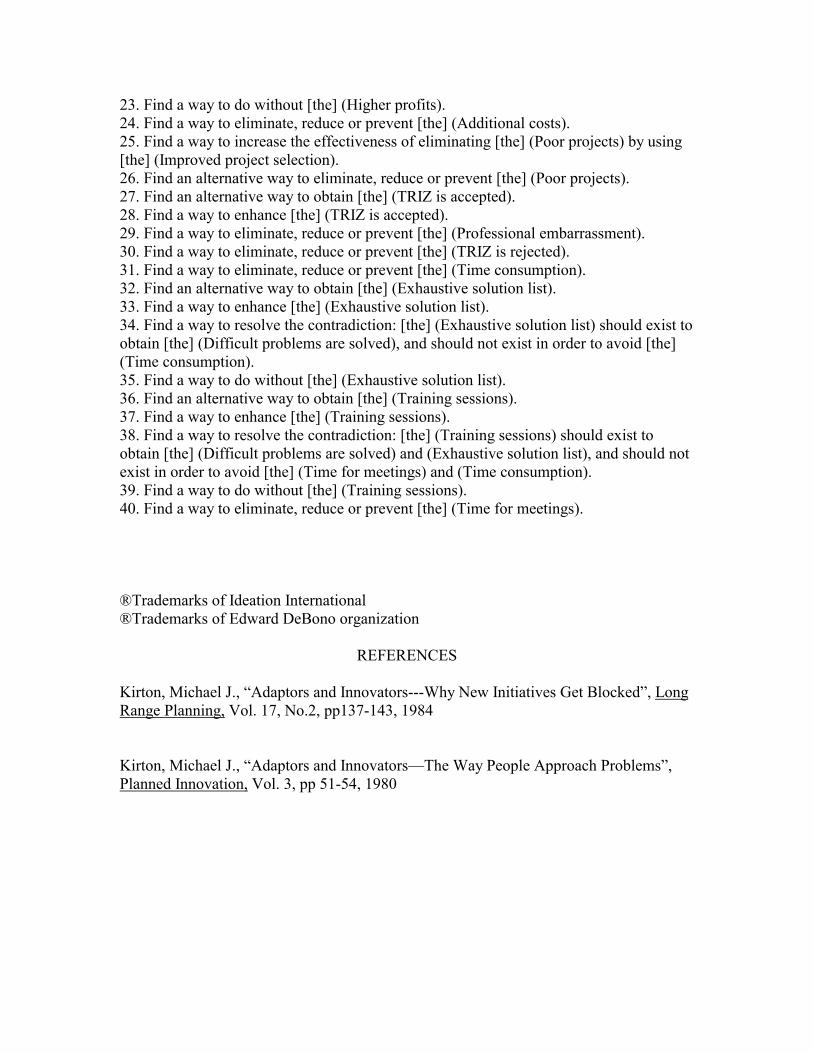
23. Find a way to do without [the] (Higher profits). 24. Find a way to eliminate, reduce or prevent [the] (Additional costs). 25. Find a way to increase the effectiveness of eliminating [the] (Poor projects) by using [the] (Improved project selection). 26. Find an alternative way to eliminate, reduce or prevent [the] (Poor projects). 27. Find an alternative way to obtain [the] (TRIZ is accepted). 28. Find a way to enhance [the] (TRIZ is accepted). 29. Find a way to eliminate, reduce or prevent [the] (Professional embarrassment). 30. Find a way to eliminate, reduce or prevent [the] (TRIZ is rejected). 31. Find a way to eliminate, reduce or prevent [the] (Time consumption). 32. Find an alternative way to obtain [the] (Exhaustive solution list). 33. Find a way to enhance [the] (Exhaustive solution list). 34. Find a way to resolve the contradiction: [the] (Exhaustive solution list) should exist to obtain [the] (Difficult problems are solved), and should not exist in order to avoid [the] (Time consumption). 35. Find a way to do without [the] (Exhaustive solution list). 36. Find an alternative way to obtain [the] (Training sessions). 37. Find a way to enhance [the] (Training sessions). 38. Find a way to resolve the contradiction: [the] (Training sessions) should exist to obtain [the] (Difficult problems are solved) and (Exhaustive solution list), and should not exist in order to avoid [the] (Time for meetings) and (Time consumption). 39. Find a way to do without [the] (Training sessions). 40. Find a way to eliminate, reduce or prevent [the] (Time for meetings). ®Trademarks of Ideation International ®Trademarks of Edward DeBono organization
REFERENCES
Kirton, Michael J., “Adaptors and Innovators---Why New Initiatives Get Blocked”, Long Range Planning, Vol. 17, No.2, pp137-143, 1984 Kirton, Michael J., “Adaptors and Innovators—The Way People Approach Problems”, Planned Innovation, Vol. 3, pp 51-54, 1980

ON THE HISTORY OF SEPARATION PRINCIPLES =========================================
Y. B. Karasik e-mail: [email protected]
Introduction ============= As is known, the concept of physical contradictions is one of the cornerstones of TRIZ. It is also well known that they are resolved with the help of so called "separation principles". What is the history behind the idea of separation principles in the whole and each and every principle in particular? The present paper aims to answer this question. Year 1973 AD. Due to G. Filkovsky [1], the concept of physical contradictions was proposed by Perelstein, a physicist. It should had happened before the fall of 1973 because when in the fall of 1973 I enrolled The Azerbaijan Public Institute for Inventive Creativity (AzOIIT), we were already taught physical contradictions. We were also taught that they are resolved by separating contradictory requirement either in space or time. Who was behind the latter idea I do not know but it is plausible to guess that he was the same Perelstein for whom as a physicist space-time thinking was natural. Shortly afterwards I was also exposed to the work by Irina Flikstein whose main thesis was that strong inventions are obtained by applying not one of 40 methods/principles of invention but by applying them in pairs: principle + anti-principle. For example, splinting was recommended to apply along with uniting. Being a mathematician, I immediately noticed that something is wrong with this idea because application of an operator/action along with its anti-operator/anti-action should leave system intact. This was the starting point of my research. The examples in the Flikstein's work clearly showed that both operator and anti-operator were applied. But how come that they did not cancel each other, I wondered? OK, in mechanics opposite forces do not cancel each other if they are applied to different portions/sides of an object. On the contrary, opposite forces applied to different sides can transform the object or set it into rotation. Maybe the inventive operators/principles are also applied to different "sides" of a system, I questioned? Thus, the idea of conjugate "sides" of a system was born. The "sides" were defined merely as conjugate views or representations of a system. For example, you can view a system as a whole or can view it as consisting of parts, etc. My thesis was that strong inventions were obtained by applying the opposite operators to such conjugate "sides" (views, representations) of a system.
By then I already was taught that strong inventions are results of resolving physical contradictions. It was not difficult to guess that physical contradictions are hence resolved by applying opposite operators to conjugate "sides" of system. In other words, if we are given a contradiction "object should have property A and should not have property A" then it will turn to be resolved if one "side" of the object has property A and the conjugate "side" does not have it. I called this principle "the principle of resolving physical contradictions by separating contradictory requirements between conjugate/dual sides of an object". The separation in space-time turned out to be a particular case of this principle. The other separation principles immediately followed. For example, if we use "parts and the whole” conjugate "sides" of object, then we obtain a new separation principle: the parts of a system should have property A but as a whole it should not have property A. The manuscript outlining this theory and presenting a number of new separation principles was published in 1974 [2]. Years 1974 - 1980. =================== The theory did not get blessing from G. S. Altshuller. He continued to insist that contradictory requirements can be only separated either in space or time. "What else can be?” - he questioned - "It is physical contradictions. Physics deals with space and time..." The tables turned in 1975 when Altshuller suddenly recognized separation between parts and the whole. I was elevated. I recollected him his own argument against my theory that physics deals with space and time and hence physical contradictions can be only resolved by separating in space or time. Separation between parts and the whole obviously did not support this thesis. Then Altshuller countered that contradictory requirements can also be separated in phase transitions. In other words, if he acknowledged that he was wrong with respect to the number of possible methods then let him be right with respect to what nature such methods should have. They should be something of physics! To this day I view this method (separation in phase transition) as something artificial born in the heat of polemics. To this day I do not see the usefulness of this method as well as where is separation here. To this day I consider it as alien to the idea of separation and as absolutely redundant. The two new methods were incorporated into ARIZ and first officially published in 1979 in "Creativity as an exact science" [3]. I continued to persuade Altshuller that there are an indefinite number of separation principles all derived from the above theory till 1980. In 1980 the theory was officially published in "The technology and science" magazine [4] but Altshuller broadcasted the information to that effect that my publication is not a TRIZ one. Why Altshuller rejected the other separation principles? I have the only explanation to that. I could not provide examples on these principles from mechanical (or electro-mechanical) engineering - the only field of engineering Altshuller knew and understood, but which was not the area of my
expertise. On the other hand, my examples from software and algorithms engineering were unclear to him. Epilogue. ========= Since 1981 our ways diverged. I did not meet Altshuller for years. In the meantime I wrote and published papers not necessarily related to separation principles. One of them just dealt with some algebra of system transformations [5]. In particular, it discussed the following transformations:
When in 1986 I bought the latest Altshuller's book "Find an idea" [6], I was surprised to learn that the transformations I described were incorporated into ARIZ-85 as guess what? As new separation principles! Probably for Altshuller I became inseparable from separation. R E F E R E N C E S =====================
1. G. Filkovsky, internet posting www.jps.net/triz/Gospel_GF.htm 2. Y. B. Karasik, The mathematical foundation of the theory of heuristic methods, (in "Towards the general theory of creativity", G. S. Altshuller ed., Baku, 1974). 3. G. S. Altshuller, "Creativity as an exact science", Moscow, 1979 (in Russian). Translated into English by Anthony White, published by Gordon and Breach, 1988. 4. Y. B. Karasik, The studies on dualities, "The technology and science" magazine of the USSR Council of Scientific and Engineering Societies, No. 3, 1980, pp. 27--28. 5. Y. B. Karasik, Algebra of intuition, "Chemistry & Life" magazine of the USSR Academy of Science, No. 4, 1982, pp. 48--49. 6. G. S. Altshuller, "Find an idea", Novosibirsk, 1986 (in Russian).
About the author: Yevgeny B. Karasik studied TRIZ of the day at Azerbaijan Public Institute for Inventive Creativity (founded by G. S. Altshuller) in Baku from 1973 to 1975. Since 1974 he became a member of the small group of researchers centered around Altshuller that gave TRIZ its contemporary shape. Dr. Karasik holds Ph.D. in computer science from Tel Aviv University awarded for his ground- breaking work on optical models of computation. He is the author of more than 40 research papers on optical information processing and optical algorithms. He is also the author of a number of key concepts in TRIZ. He currently resides in Ottawa, Canada, the hub of numerous high-tech companies.
A Anti-A A A + anti-A etc.


Proceedings of ICAD2000 First International Conference on Axiomatic Design
Cambridge, MA – June 21-23, 2000 ICAD030
Copyright © #### by ICAD2000 Page: 1/1
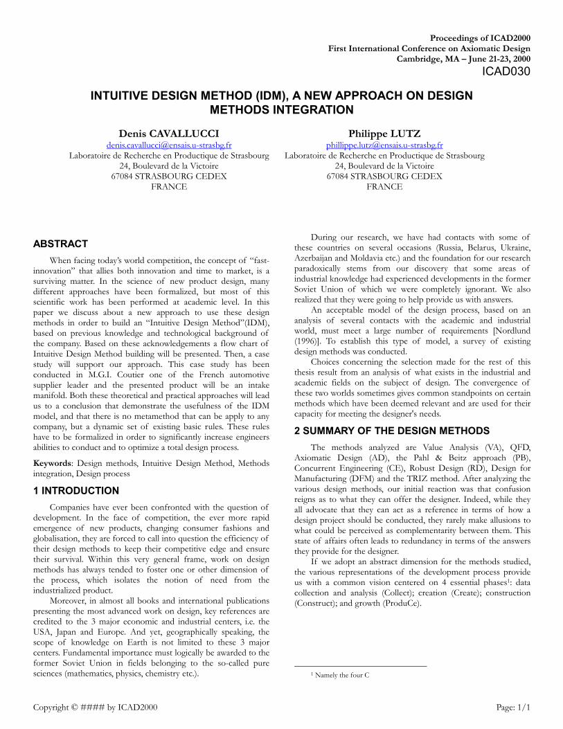
ABSTRACT When facing today’s world competition, the concept of “fast-
innovation” that allies both innovation and time to market, is a surviving matter. In the science of new product design, many different approaches have been formalized, but most of this scientific work has been performed at academic level. In this paper we discuss about a new approach to use these design methods in order to build an “Intuitive Design Method”(IDM), based on previous knowledge and technological background of the company. Based on these acknowledgements a flow chart of Intuitive Design Method building will be presented. Then, a case study will support our approach. This case study has been conducted in M.G.I. Coutier one of the French automotive supplier leader and the presented product will be an intake manifold. Both these theoretical and practical approaches will lead us to a conclusion that demonstrate the usefulness of the IDM model, and that there is no metamethod that can be apply to any company, but a dynamic set of existing basic rules. These rules have to be formalized in order to significantly increase engineers abilities to conduct and to optimize a total design process.
Keywords: Design methods, Intuitive Design Method, Methods integration, Design process
1 INTRODUCTION Companies have ever been confronted with the question of
development. In the face of competition, the ever more rapid emergence of new products, changing consumer fashions and globalisation, they are forced to call into question the efficiency of their design methods to keep their competitive edge and ensure their survival. Within this very general frame, work on design methods has always tended to foster one or other dimension of the process, which isolates the notion of need from the industrialized product.
Moreover, in almost all books and international publications presenting the most advanced work on design, key references are credited to the 3 major economic and industrial centers, i.e. the USA, Japan and Europe. And yet, geographically speaking, the scope of knowledge on Earth is not limited to these 3 major centers. Fundamental importance must logically be awarded to the former Soviet Union in fields belonging to the so-called pure sciences (mathematics, physics, chemistry etc.).
During our research, we have had contacts with some of these countries on several occasions (Russia, Belarus, Ukraine, Azerbaijan and Moldavia etc.) and the foundation for our research paradoxically stems from our discovery that some areas of industrial knowledge had experienced developments in the former Soviet Union of which we were completely ignorant. We also realized that they were going to help provide us with answers.
An acceptable model of the design process, based on an analysis of several contacts with the academic and industrial world, must meet a large number of requirements [Nordlund (1996)]. To establish this type of model, a survey of existing design methods was conducted.
Choices concerning the selection made for the rest of this thesis result from an analysis of what exists in the industrial and academic fields on the subject of design. The convergence of these two worlds sometimes gives common standpoints on certain methods which have been deemed relevant and are used for their capacity for meeting the designer's needs.
2 SUMMARY OF THE DESIGN METHODS The methods analyzed are Value Analysis (VA), QFD,
Axiomatic Design (AD), the Pahl & Beitz approach (PB), Concurrent Engineering (CE), Robust Design (RD), Design for Manufacturing (DFM) and the TRIZ method. After analyzing the various design methods, our initial reaction was that confusion reigns as to what they can offer the designer. Indeed, while they all advocate that they can act as a reference in terms of how a design project should be conducted, they rarely make allusions to what could be perceived as complementarity between them. This state of affairs often leads to redundancy in terms of the answers they provide for the designer.
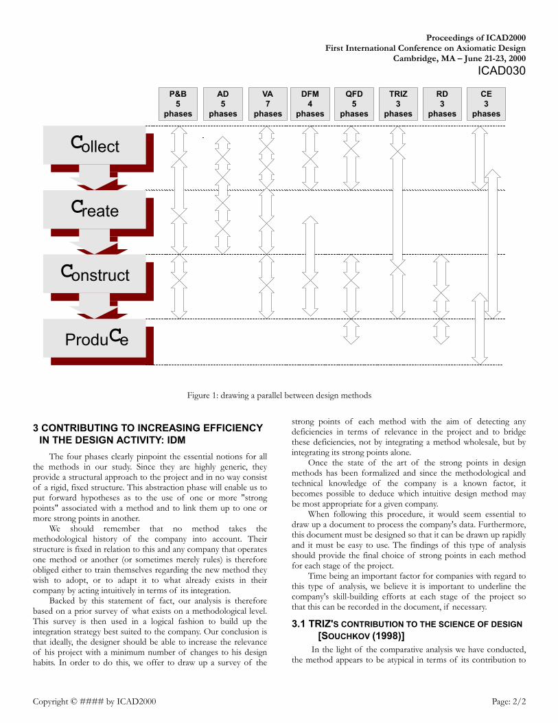
If we adopt an abstract dimension for the methods studied, the various representations of the development process provide us with a common vision centered on 4 essential phases1: data collection and analysis (Collect); creation (Create); construction (Construct); and growth (ProduCe).
1 Namely the four C
INTUITIVE DESIGN METHOD (IDM), A NEW APPROACH ON DESIGN METHODS INTEGRATION
Denis CAVALLUCCI [email protected]
Laboratoire de Recherche en Productique de Strasbourg 24, Boulevard de la Victoire
67084 STRASBOURG CEDEX FRANCE
Philippe LUTZ [email protected]
Laboratoire de Recherche en Productique de Strasbourg 24, Boulevard de la Victoire
67084 STRASBOURG CEDEX FRANCE
Proceedings of ICAD2000 First International Conference on Axiomatic Design
Cambridge, MA – June 21-23, 2000 ICAD030
Copyright © #### by ICAD2000 Page: 2/2
Figure 1: drawing a parallel between design methods
3 CONTRIBUTING TO INCREASING EFFICIENCY IN THE DESIGN ACTIVITY: IDM
The four phases clearly pinpoint the essential notions for all the methods in our study. Since they are highly generic, they provide a structural approach to the project and in no way consist of a rigid, fixed structure. This abstraction phase will enable us to put forward hypotheses as to the use of one or more "strong points" associated with a method and to link them up to one or more strong points in another.
We should remember that no method takes the methodological history of the company into account. Their structure is fixed in relation to this and any company that operates one method or another (or sometimes merely rules) is therefore obliged either to train themselves regarding the new method they wish to adopt, or to adapt it to what already exists in their company by acting intuitively in terms of its integration.
Backed by this statement of fact, our analysis is therefore based on a prior survey of what exists on a methodological level. This survey is then used in a logical fashion to build up the integration strategy best suited to the company. Our conclusion is that ideally, the designer should be able to increase the relevance of his project with a minimum number of changes to his design habits. In order to do this, we offer to draw up a survey of the
strong points of each method with the aim of detecting any deficiencies in terms of relevance in the project and to bridge these deficiencies, not by integrating a method wholesale, but by integrating its strong points alone.
Once the state of the art of the strong points in design methods has been formalized and since the methodological and technical knowledge of the company is a known factor, it becomes possible to deduce which intuitive design method may be most appropriate for a given company.
When following this procedure, it would seem essential to draw up a document to process the company's data. Furthermore, this document must be designed so that it can be drawn up rapidly and it must be easy to use. The findings of this type of analysis should provide the final choice of strong points in each method for each stage of the project.
Time being an important factor for companies with regard to this type of analysis, we believe it is important to underline the company's skill-building efforts at each stage of the project so that this can be recorded in the document, if necessary.
3.1 TRIZ'S CONTRIBUTION TO THE SCIENCE OF DESIGN [SOUCHKOV (1998)]
In the light of the comparative analysis we have conducted, the method appears to be atypical in terms of its contribution to
C ollect
C re ate
C onstruct
Produ C e
RD 3
phases
TRIZ 3
phases
QFD 5
phases
DFM 4
phases
VA 7
phases
AD 5
phases
CE 3
phases
P&B 5
phases
Intuitive Design METHOD (IDM), a new approach on Design Methods integration First International Conference on Axiomatic Design
Cambridge, MA – June 21-23, 2000
Copyright © #### by ICAD2000 Page: 3/3
design methods. Indeed, its relevance and operational profile are fundamentally different from those of other methods studied. This is particularly true for the creativity phase which, although its is barely relevant in other methods, is the strong point of TRIZ, since the methodological effort of a company wishing to improve its design process will no doubt occur with TRIZ.
4 INTEGRATION METHOD
4.1 DIFFICULTIES IN APPLYING TRADITIONAL METHODS In the introduction to this section, we will give a brief
summary of the difficulties linked with applying the design methods quoted in the previous section. The term "difficulty" encompasses in particular: • Learning difficulties: this arises from the fact that the
methods have often been developed in research laboratories and are still not widespread in companies. The fact that training programs for some of them are virtually non-existent in engineering courses adds to the fact that the learning process presents a difficulty for the industrialist.
• Difficulties linked with doubts surrounding the profitability of the investment. The financial aspect obviously presents a difficulty and a major obstacle to the integration of the new method. The economic context merely accentuates this difficulty since it is not easy, on first contact with a new method, to grasp the return on investment in man-hours that it will generate. The training/counseling aspect is added to the cost as soon as it becomes apparent that the company lacks skill with regard to the method.
4.2 MEASURING THE GAP Our analysis of the various design methods has revealed a
certain amount of complementarity, which has sometimes led to research work [Malmqvist (1996)] [Schulz (1999)]. It would seem logical that the ideal combination would consist in collecting and analyzing data with QFD, generating concepts with TRIZ and ensuring the optimization of parameters with Robust Design [Verduyn (1995)]. Yet this combination is only ideal from a
theoretical point of view. A whole panoply of difficulties awaits designers who wish to combine these methods. • Difficulties in skill-building for a set of methods which are
not mastered. • Difficulties in combining methods in the same project or the
need to create interfaces between them. • The time-span of the project is increased significantly due to
the inertia inherent in applying three methods. Our conclusion is that ideally, the designer should be able to
increase the relevance of his project with a minimum number of changes to his design habits. In order to do this, we offer to draw up a survey of the strong points of each method with the aim of detecting any deficiencies in terms of relevance in the project and to bridge these deficiencies, not by integrating a method wholesale, but by integrating its strong points alone.
4.3 HIGHLIGHTING THE STRONG POINTS OF DESIGN METHODS
The classification of strong points for each design method has been formalized and deliberately restricted to four since, beyond this number, it becomes difficult to identify the real advantage of the point in question. The object of this formalization is to offer the company a strategic choice in its decisions regarding the orientation of its design method.
The stages and generation of the intuitive design method
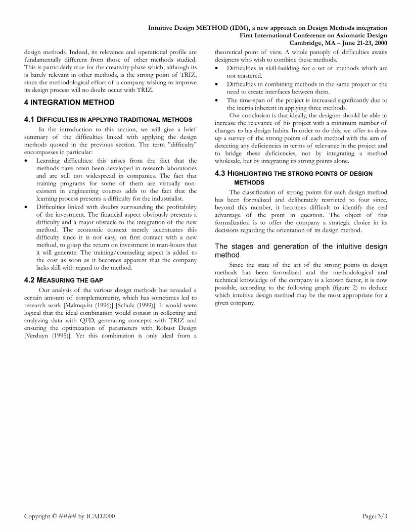
Since the state of the art of the strong points in design methods has been formalized and the methodological and technical knowledge of the company is a known factor, it is now possible, according to the following graph (figure 2) to deduce which intuitive design method may be the most appropriate for a given company.
Proceedings of ICAD2000 First International Conference on Axiomatic Design
Cambridge, MA – June 21-23, 2000 ICAD030
Copyright © #### by ICAD2000 Page: 4/4
Figure 2: Global process of defining the Intuitive Design Method
5 IMPROVEMENT IN THE PERFORMANCE OF THE DESIGN ACTIVITY AT MGI COUTIER An industrial application has been developed within the
frame of this research activity. It was conducted at the company MGI Coutier (an automobile parts manufacturer). The project selected as the presentation medium was the intake manifold. The intake manifold is an important element in the gas inlet zone of the cylinders. Its shape and the lack of space available under the bonnet mean that today, it is an element which has undergone little optimization in terms of its structure and shape. With the aim of improving its performance in use, the intuitive design method developed in our research project has been
applied to generate innovative concepts which may solve the major problem related to its shape.
5.1 INCREASING DESIGN EFFICIENCY
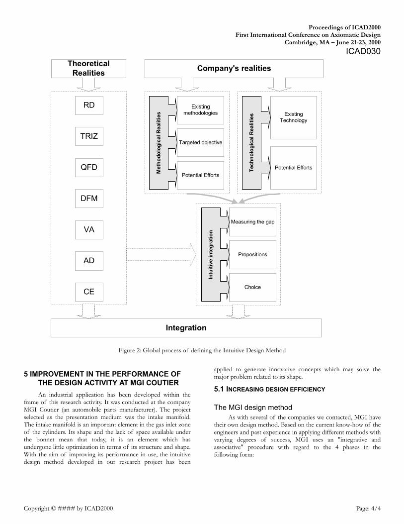
The MGI design method As with several of the companies we contacted, MGI have
their own design method. Based on the current know-how of the engineers and past experience in applying different methods with varying degrees of success, MGI uses an "integrative and associative" procedure with regard to the 4 phases in the following form:
Met
hodo
logi
cal R
ealit
ies
Existingmethodologies
Targeted objective
Potential Efforts
Tech
nolo
gica
l Rea
litie
s ExistingTechnology
Potential Efforts
Intu
itive
inte
grat
ion
Measuring the gap
Propositions
Choice
RD
TRIZ
QFD
DFM
VA
AD
CE
TheoreticalRealities Company's realities
Integration
Proceedings of ICAD2000 First International Conference on Axiomatic Design
Cambridge, MA – June 21-23, 2000 ICAD030
Copyright © #### by ICAD2000 Page: 5/5
Figure 3 : Stages in MGI’s design with regard to the 4 phases
The specificity of design activity at MGI lies in the fact that
upstream research and computation are centralized at a research center located in the Bas-Rhin in France. This research center employs some 40 engineers and 20 technicians and is in charge of research on new products and systems. The notion of novelty lies in the aptitude of development centers to conduct a study independent of the research center (re-looking, minor developments etc.). Upstream studies requiring the backing of research (materials, process, technology, innovation etc.) are initially dealt with by the research center before being transferred to development and industrialization in the various development centers. It should be noted that development centers may deal with a study independently while, in terms of resources, calling solely on the computational center (simulations, flow, analyses etc.).
Analysis of the efficiency of the design activity Using items returned by customers and personal analyses as
our basis, we were able to compile data on the aptitude of MGI's project teams to overcome the obstacles inherent in the 4 phases.
We noted that the collecting phase is heavily invested by QFD [Hauser (1988)] due to the fact that one of MGI's sizeable contractors impose skill-building on them for this tool, underlining the importance of mastering this method.
Synthesis and recommendations for skill-building in MGI's design activity
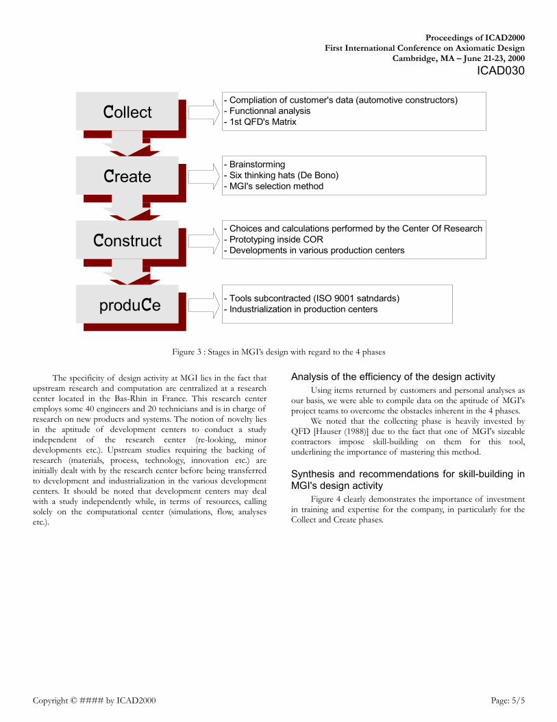
Figure 4 clearly demonstrates the importance of investment in training and expertise for the company, in particularly for the Collect and Create phases.
Collect
Create
Construct
produCe
- Compliation of customer's data (automotive constructors)- Functionnal analysis- 1st QFD's Matrix
- Brainstorming- Six thinking hats (De Bono)- MGI's selection method
- Choices and calculations performed by the Center Of Research- Prototyping inside COR- Developments in various production centers
- Tools subcontracted (ISO 9001 satndards)- Industrialization in production centers
Intuitive Design METHOD (IDM), a new approach on Design Methods integration First International Conference on Axiomatic Design
Cambridge, MA – June 21-23, 2000
Copyright © #### by ICAD2000 Page: 6/6
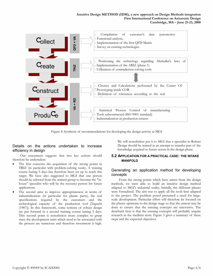
Figure 4: Synthesis of recommendations for developing the design activity at MGI
Details on the actions undertaken to increase efficiency in design
Our assessment suggests that two key actions should therefore be undertaken: • The first concerns the acquisition of the strong points in
TRIZ (in particular with problem-solving tools). A training course lasting 5 days has therefore been set up to reach this target. We have also suggested to MGI that one person should be selected from the trained group to become the "in-house" specialist who will be the resource person for future applications.
• The second aims to improve appropriateness in terms of industrialization (in particular for plastic parts), the real specifications required by the customers and the technological capacity of the production tool [Taguchi (1987)]. In this framework, some notions of robust design are put forward in a second training course lasting 5 days. This second point is nonetheless more complex to grasp since the development units which need to be associated with the process are numerous and therefore investment is high.
We will nonetheless put it to MGI that a specialist in Robust Design should be trained in an attempt to transfer part of the knowledge acquired to future actors in the design phase.
5.2 APPLICATION FOR A PRACTICAL CASE: THE INTAKE MANIFOLD
Generating an application method for developing concepts
From the strong points which have arisen from the design methods, we were able to build an intuitive design method adapted to MGI's industrial reality. Initially, the different phases were formalized. The aim was to apply all the tools best adapted to the project. The problem posed presented a need for large-scale development. Particular effort will therefore be focused on the phases upstream to the design stage so that the utmost may be done to ensure that the ensuing concepts are innovative. The drawback here is that the ensuing concepts will probably require research in the medium term. Figure 5 gives a summary of these steps and the expected objectives.
C ollect
C re ate
C onstruct
Produ C e
- Compilation of customer's data (automotive )- Functional analysis,
- Implementation of the first QFD Matrix - Survey on existing technologies
- Positioning the technology regarding Altshuller's laws of l i- Implementation of the ARIZ (phase 1)
- Utilization of contradiction solving tools
- Choices and Calculations performed by the Center Of R h- Prototyping inside COR - Definition of tolerances according to the real
d
- Statistical Process Control of manufacturing - Tools subcontracted (ISO 9001 standard) - Industrialization in production centers
QFD
+ V
A TR
IZ
VA +
RD
Intuitive Design METHOD (IDM), a new approach on Design Methods integration First International Conference on Axiomatic Design
Cambridge, MA – June 21-23, 2000
Copyright © #### by ICAD2000 Page: 7/7
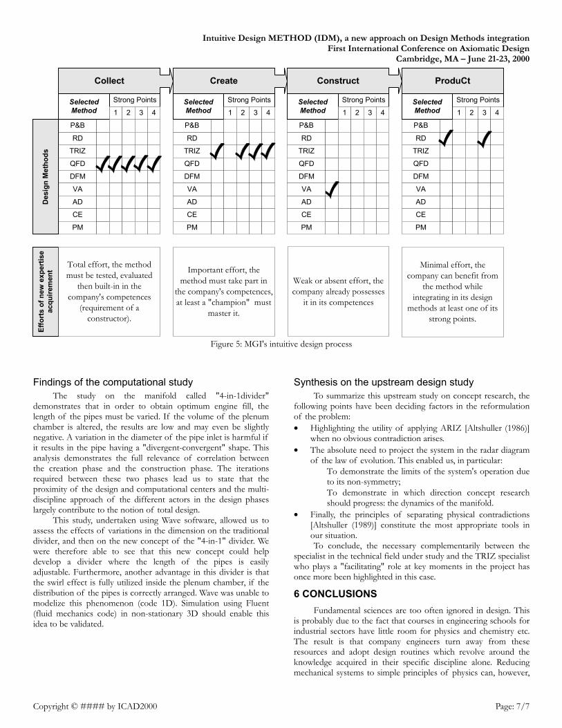
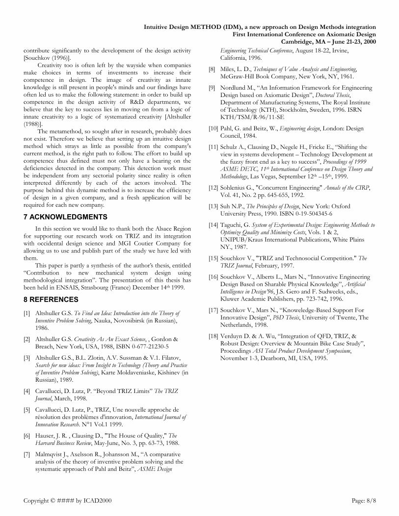
Figure 5: MGI's intuitive design process
Findings of the computational study The study on the manifold called "4-in-1divider"
demonstrates that in order to obtain optimum engine fill, the length of the pipes must be varied. If the volume of the plenum chamber is altered, the results are low and may even be slightly negative. A variation in the diameter of the pipe inlet is harmful if it results in the pipe having a "divergent-convergent" shape. This analysis demonstrates the full relevance of correlation between the creation phase and the construction phase. The iterations required between these two phases lead us to state that the proximity of the design and computational centers and the multi-discipline approach of the different actors in the design phases largely contribute to the notion of total design.
This study, undertaken using Wave software, allowed us to assess the effects of variations in the dimension on the traditional divider, and then on the new concept of the "4-in-1" divider. We were therefore able to see that this new concept could help develop a divider where the length of the pipes is easily adjustable. Furthermore, another advantage in this divider is that the swirl effect is fully utilized inside the plenum chamber, if the distribution of the pipes is correctly arranged. Wave was unable to modelize this phenomenon (code 1D). Simulation using Fluent (fluid mechanics code) in non-stationary 3D should enable this idea to be validated.
Synthesis on the upstream design study To summarize this upstream study on concept research, the
following points have been deciding factors in the reformulation of the problem: • Highlighting the utility of applying ARIZ [Altshuller (1986)]
when no obvious contradiction arises. • The absolute need to project the system in the radar diagram
of the law of evolution. This enabled us, in particular: � To demonstrate the limits of the system's operation due
to its non-symmetry; � To demonstrate in which direction concept research
should progress: the dynamics of the manifold. • Finally, the principles of separating physical contradictions
[Altshuller (1989)] constitute the most appropriate tools in our situation. To conclude, the necessary complementarily between the
specialist in the technical field under study and the TRIZ specialist who plays a "facilitating" role at key moments in the project has once more been highlighted in this case.
6 CONCLUSIONS Fundamental sciences are too often ignored in design. This
is probably due to the fact that courses in engineering schools for industrial sectors have little room for physics and chemistry etc. The result is that company engineers turn away from these resources and adopt design routines which revolve around the knowledge acquired in their specific discipline alone. Reducing mechanical systems to simple principles of physics can, however,
ConstructCreateCollect ProduCt
RD
TRIZ
QFD
DFM
VA
AD
CE
PM
P&B
Strong PointsSelectedMethod 1 2 3 4
RD
TRIZ
QFD
DFM
AD
P&B
Strong PointsSelectedMethod 1 2 3 4
RD
TRIZ
QFD
DFM
AD
P&B
Strong PointsSelectedMethod 1 2 3 4
RD
TRIZ
QFD
DFM
AD
P&B
Strong PointsSelectedMethod 1 2 3 4
Effo
rts o
f new
exp
ertis
eac
quire
men
t
Total effort, the methodmust be tested, evaluated
then built-in in thecompany's competences
(requirement of aconstructor).
Desi
gn M
etho
ds
Important effort, themethod must take part in
the company's competences,at least a "champion" must
master it.
Weak or absent effort, thecompany already possesses
it in its competences
Minimal effort, thecompany can benefit from
the method whileintegrating in its design
methods at least one of itsstrong points.
VA
CE
PM
VA
CE
PM
VA
CE
PM
Intuitive Design METHOD (IDM), a new approach on Design Methods integration First International Conference on Axiomatic Design
Cambridge, MA – June 21-23, 2000
Copyright © #### by ICAD2000 Page: 8/8
contribute significantly to the development of the design activity [Souchkov (1996)].
Creativity too is often left by the wayside when companies make choices in terms of investments to increase their competence in design. The image of creativity as innate knowledge is still present in people's minds and our findings have often led us to make the following statement: in order to build up competence in the design activity of R&D departments, we believe that the key to success lies in moving on from a logic of innate creativity to a logic of systematized creativity [Altshuller (1988)].
The metamethod, so sought after in research, probably does not exist. Therefore we believe that setting up an intuitive design method which strays as little as possible from the company's current method, is the right path to follow. The effort to build up competence thus defined must not only have a bearing on the deficiencies detected in the company. This detection work must be independent from any sectorial polarity since reality is often interpreted differently by each of the actors involved. The purpose behind this dynamic method is to increase the efficiency of design in a given company, and a fresh application will be required for each new company.
7 ACKNOWLEDGMENTS In this section we would like to thank both the Alsace Region
for supporting our research work on TRIZ and its integration with occidental design science and MGI Coutier Company for allowing us to use and publish part of the study we have led with them.
This paper is partly a synthesis of the author’s thesis, entitled “Contribution to new mechanical system design using methodological integration”. The presentation of this thesis has been held in ENSAIS, Strasbourg (France) December 14th 1999.
8 REFERENCES
[1] Altshuller G.S. To Find an Idea: Introduction into the Theory of Inventive Problem Solving, Nauka, Novosibirsk (in Russian), 1986.
[2] Altshuller G.S. Creativity As An Exact Science, , Gordon & Breach, New York, USA, 1988, ISBN 0-677-21230-5
[3] Altshuller G.S., B.L. Zlotin, A.V. Sussman & V.1. Filatov, Search for new ideas: From Insight to Technology (Theory and Practice of Inventive Problem Solving), Karte Moldaveniaske, Kishinev (in Russian), 1989.
[4] Cavallucci, D. Lutz, P. “Beyond TRIZ Limits” The TRIZ Journal, March, 1998.
[5] Cavallucci, D. Lutz, P., TRIZ, Une nouvelle approche de résolution des problèmes d'innovation, International Journal of Innovation Research. N°1 Vol.1 1999.
[6] Hauser, J. R. , Clausing D., "The House of Quality," The Harvard Business Review, May-June, No. 3, pp. 63-73, 1988.
[7] Malmqvist J., Axelsson R., Johansson M., “A comparative analysis of the theory of inventive problem solving and the systematic approach of Pahl and Beitz”, ASME Design
Engineering Technical Conference, August 18-22, Irvine, California, 1996.
[8] Miles, L. D., Techniques of Value Analysis and Engineering, McGraw-Hill Book Company, New York, NY, 1961.
[9] Nordlund M., “An Information Framework for Engineering Design based on Axiomatic Design”, Doctoral Thesis, Department of Manufacturing Systems, The Royal Institute of Technology (KTH), Stockholm, Sweden, 1996. ISRN KTH/TSM/R-96/11-SE
[10] Pahl, G. and Beitz, W., Engineering design, London: Design Council, 1984.
[11] Schulz A., Clausing D., Negele H., Fricke E., “Shifting the view in systems development – Technology Development at the fuzzy front end as a key to success”, Proceedings of 1999 ASME DETC, 11th International Conference on Design Theory and Methodology, Las Vegas, September 12th –15th, 1999.
[12] Sohlenius G., "Concurrent Engineering" Annals of the CIRP, Vol. 41, No. 2 pp. 645-655, 1992.
[13] Suh N.P., The Principles of Design, New York: Oxford University Press, 1990. ISBN 0-19-504345-6
[14] Taguchi, G. System of Experimental Design: Engineering Methods to Optimize Quality and Minimize Costs, Vols. 1 & 2, UNIPUB/Kraus International Publications, White Plains NY., 1987.
[15] Souchkov V., "TRIZ and Technosocial Competition." The TRIZ Journal, February, 1997.
[16] Souchkov V., Alberts L., Mars N., “Innovative Engineering Design Based on Sharable Physical Knowledge”, Artificial Intelligence in Design’96, J.S. Gero and F. Sudweeks, eds., Kluwer Academic Publishers, pp. 723-742, 1996.
[17] Souchkov V., Mars N., “Knoweledge-Based Support For Innovative Design”, PhD Thesis, University of Twente, The Netherlands, 1998.
[18] Verduyn D. & A. Wu, “Integration of QFD, TRIZ, & Robust Design: Overview & Mountain Bike Case Study”, Proceedings ASI Total Product Development Symposium, November 1-3, Dearborn, MI, USA, 1995.

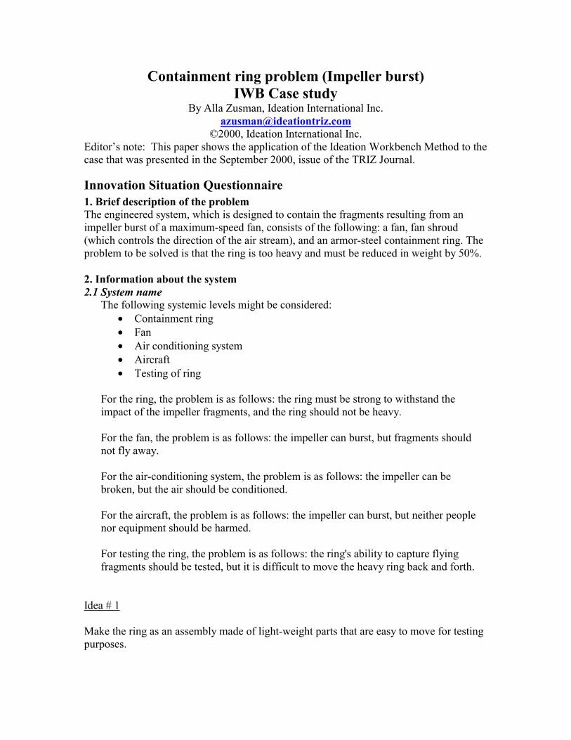
Containment ring problem (Impeller burst) IWB Case study
By Alla Zusman, Ideation International Inc. [email protected]
©2000, Ideation International Inc. Editor’s note: This paper shows the application of the Ideation Workbench Method to the case that was presented in the September 2000, issue of the TRIZ Journal.
Innovation Situation Questionnaire 1. Brief description of the problem The engineered system, which is designed to contain the fragments resulting from an impeller burst of a maximum-speed fan, consists of the following: a fan, fan shroud (which controls the direction of the air stream), and an armor-steel containment ring. The problem to be solved is that the ring is too heavy and must be reduced in weight by 50%. 2. Information about the system 2.1 System name
The following systemic levels might be considered: • Containment ring • Fan • Air conditioning system • Aircraft • Testing of ring
For the ring, the problem is as follows: the ring must be strong to withstand the impact of the impeller fragments, and the ring should not be heavy. For the fan, the problem is as follows: the impeller can burst, but fragments should not fly away. For the air-conditioning system, the problem is as follows: the impeller can be broken, but the air should be conditioned. For the aircraft, the problem is as follows: the impeller can burst, but neither people nor equipment should be harmed. For testing the ring, the problem is as follows: the ring's ability to capture flying fragments should be tested, but it is difficult to move the heavy ring back and forth.
Idea # 1
Make the ring as an assembly made of light-weight parts that are easy to move for testing purposes.
We can influence two systemic levels: the ring and the fan assembly. Let’s select the fan assembly as the system to be considered.
2.2 System structure The fan assembly consists of the following elements:
• fan • motor • shaft • motor support • containment ring • connectors or support to keep the ring
2.3 Functioning of the system
The primary useful function of the fan is to supply (move) air for the air conditioning system. The fan rotates quickly and moves air. The air is conditioned so that the aircraft cabin can be supplied with conditioned air.
2.4 System environment Other parts of the air conditioning system:
• pipes • heat exchanger • airflow distributors
Other systems located nearby:
• aircraft covering • equipment
Other system interacting with the fan and air conditioning system:
• electrical power supply • air supply • exhaust air removal • vibration dampers
Conditions around the system: indoor conditions
3. Information about the problem situation 3.1 Problem that should be resolved
Reduce the weight of the ring by 50%. The primary harmful function of the given system (the fan assembly) is that impeller fragments fly away if the impeller bursts.
3.2 Mechanism causing the problem The containment ring must be strong to contain the flying fragments – for this reason the ring is thick and, as a result, heavy. The cause of an impeller burst is as follows: Rotation of the fan results in centrifugal forces that "pull" the parts of the impeller. The strength of the impeller material can be compromised by material defects and fatigue. As a result, the impeller can burst, causing the impeller fragments to fly off. Due to the high speed at which the fan rotates, the flying fragments carry high energy and can harm people and other parts of the aircraft.
2.3 Undesired consequences of unresolved problem The high weight of the ring makes it difficult to carry out the routine tests required by the FAA. The "dead weight" of the aircraft equipment is also high. If the weight problem is resolved at the expense of the ring's strength, the result will be inadequate protection from the flying impeller fragments, which in turn can result in death and/or damage.
2.4 History of the problem The increased requirements for conditioning the air are met using a higher velocity airflow, but this means that the rotational speed of the fan increases. As a result, an impeller burst becomes more probable and the danger from the flying fragments increases. Because the energy of the flying fragments is increased, the ring must be stronger. As a result, the ring is heavier.
Known attempts to reduce the ring thickness resulted in a reduction in strength.
Idea # 2 Provide high airflow with low rotational speed of the fan. Perhaps utilize several slow fans instead of one that rotates quickly
2.5 Other systems in which a similar problem exists Similar problems exist in many other areas where weight and mechanical strength are critical issues, as well as other systems for protection against flying parts. We do not have any information about how these problems have been addressed.
2.6 Other problems to be solved Use an alternative method to contain the fragments.
Make the impeller unbreakable. Others (see the problems on different systemic levels in the beginning of the ISQ).
3. Ideal vision of solution No containment ring is necessary. An impeller burst is no longer possible.
4. Available resources
Substance resources • Material of containment ring • Material of fan impeller • Other objects around • Airflow
Field resources
• Mechanical forces • Airflow energy • Electrical energy • Magnetic field (motor)
Space resources
• Space inside the ring • Space outside the ring
Time resources
• Time during which the fan is not operating • Time when the fan is operating • Time before the impeller bursts • Time after the impeller bursts
Informational resources: No special resources
Functional resources
• Rotation 5. Allowable changes to the system
• Drastic changes are allowed. • Any reduction in strength is unacceptable.
6. Criteria for selecting solution concepts
• Weight reduction of at least 30% • Cost increase of no more than 5% • About two weeks for new design • One year for implementation
7. Description of the company business environment
(Withheld)
8. Project data
(Withheld)
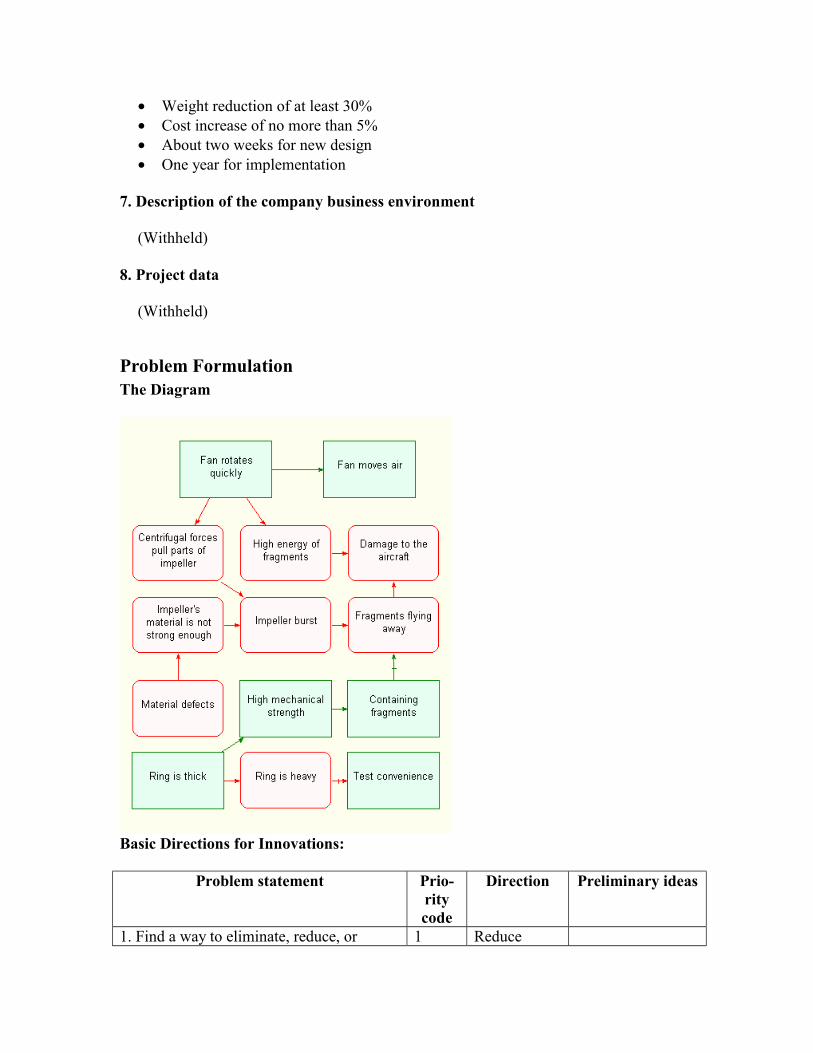
Problem Formulation The Diagram
Basic Directions for Innovations:
Problem statement Prio-rity code
Direction Preliminary ideas
1. Find a way to eliminate, reduce, or 1 Reduce
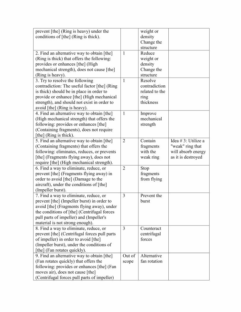
prevent [the] (Ring is heavy) under the conditions of [the] (Ring is thick).
weight or density Change the structure
2. Find an alternative way to obtain [the] (Ring is thick) that offers the following: provides or enhances [the] (High mechanical strength), does not cause [the] (Ring is heavy).
1
Reduce weight or density Change the structure
3. Try to resolve the following contradiction: The useful factor [the] (Ring is thick) should be in place in order to provide or enhance [the] (High mechanical strength), and should not exist in order to avoid [the] (Ring is heavy).
1 Resolve contradiction related to the ring thickness
4. Find an alternative way to obtain [the] (High mechanical strength) that offers the following: provides or enhances [the] (Containing fragments), does not require [the] (Ring is thick).
1 Improve mechanical strength
5. Find an alternative way to obtain [the] (Containing fragments) that offers the following: eliminates, reduces, or prevents [the] (Fragments flying away), does not require [the] (High mechanical strength).
2 Contain fragments with the weak ring
Idea # 3: Utilize a "weak" ring that will absorb energy as it is destroyed
6. Find a way to eliminate, reduce, or prevent [the] (Fragments flying away) in order to avoid [the] (Damage to the aircraft), under the conditions of [the] (Impeller burst).
2 Stop fragments from flying
7. Find a way to eliminate, reduce, or prevent [the] (Impeller burst) in order to avoid [the] (Fragments flying away), under the conditions of [the] (Centrifugal forces pull parts of impeller) and (Impeller's material is not strong enough).
3 Prevent the burst
8. Find a way to eliminate, reduce, or prevent [the] (Centrifugal forces pull parts of impeller) in order to avoid [the] (Impeller burst), under the conditions of [the] (Fan rotates quickly).
3 Counteract centrifugal forces
9. Find an alternative way to obtain [the] (Fan rotates quickly) that offers the following: provides or enhances [the] (Fan moves air), does not cause [the] (Centrifugal forces pull parts of impeller)
Out of scope
Alternative fan rotation
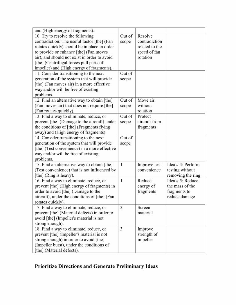
and (High energy of fragments). 10. Try to resolve the following contradiction: The useful factor [the] (Fan rotates quickly) should be in place in order to provide or enhance [the] (Fan moves air), and should not exist in order to avoid [the] (Centrifugal forces pull parts of impeller) and (High energy of fragments).
Out of scope
Resolve contradiction related to the speed of fan rotation
11. Consider transitioning to the next generation of the system that will provide [the] (Fan moves air) in a more effective way and/or will be free of existing problems.
Out of scope
12. Find an alternative way to obtain [the] (Fan moves air) that does not require [the] (Fan rotates quickly).
Out of scope
Move air without rotation
13. Find a way to eliminate, reduce, or prevent [the] (Damage to the aircraft) under the conditions of [the] (Fragments flying away) and (High energy of fragments).
Out of scope
Protect aircraft from fragments
14. Consider transitioning to the next generation of the system that will provide [the] (Test convenience) in a more effective way and/or will be free of existing problems.
Out of scope
15. Find an alternative way to obtain [the] (Test convenience) that is not influenced by [the] (Ring is heavy).
1 Improve test convenience
Idea # 4: Perform testing without removing the ring
16. Find a way to eliminate, reduce, or prevent [the] (High energy of fragments) in order to avoid [the] (Damage to the aircraft), under the conditions of [the] (Fan rotates quickly).
1 Reduce energy of fragments
Idea # 5: Reduce the mass of the fragments to reduce damage
17. Find a way to eliminate, reduce, or prevent [the] (Material defects) in order to avoid [the] (Impeller's material is not strong enough).
3 Screen material
18. Find a way to eliminate, reduce, or prevent [the] (Impeller's material is not strong enough) in order to avoid [the] (Impeller burst), under the conditions of [the] (Material defects).
3 Improve strength of impeller
Prioritize Directions and Generate Preliminary Ideas

The following preliminary ideas have been resulted from the direct analysis of the basic Directions: 3. Utilize a "weak" ring that will absorb energy as it is destroyed 4. Perform testing without removing the ring 5. Reduce the mass of the fragments to reduce damage Directions selected for further considerations Selected Basic Directions Selected Refined Directions
or Undesired factor 1. Find a way to eliminate, reduce, or prevent [the] (Ring is heavy) under the conditions of [the] (Ring is thick).
Reduce weight
4. Find an alternative way to obtain [the] (High mechanical strength) that offers the following: provides or enhances [the] (Containing fragments), does not require [the] (Ring is thick).
4.1. Improve the useful factor (High mechanical strength).
3. Try to resolve the following contradiction: The useful factor [the] (Ring is thick) should be in place in order to provide or enhance [the] (High mechanical strength), and should not exist in order to avoid [the] (Ring is heavy).
3.1. Apply separation principles to satisfy contradictory requirements related to [the] (Ring is thick).
5. Find an alternative way to obtain [the] (Containing fragments) that offers the following: eliminates, reduces, or prevents [the] (Fragments flying away), does not require [the] (High mechanical strength).
5.3. Increase effectiveness of the useful action of [the] (Containing fragments).
Protect from fire or explosion 7. Find a way to eliminate, reduce, or prevent [the] (Impeller burst) in order to avoid [the] (Fragments flying away), under the conditions of [the] (Centrifugal forces pull parts of impeller) and (Impeller's material is not strong enough).
Reduce deformation, displacement, shock, vibration or destruction
15. Find an alternative way to obtain [the] (Test convenience) that is not influenced by [the] (Ring is heavy).
15.1. Improve the useful factor (Test convenience).
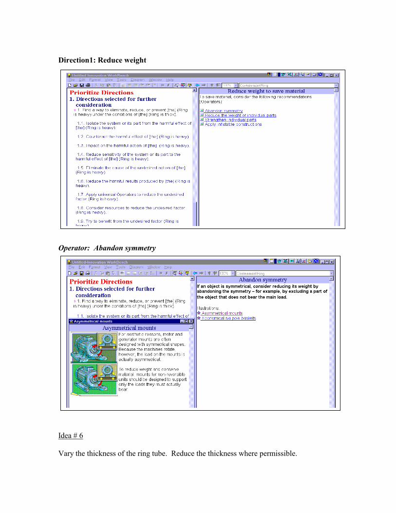
Direction1: Reduce weight Operator: Abandon symmetry Idea # 6 Vary the thickness of the ring tube. Reduce the thickness where permissible.
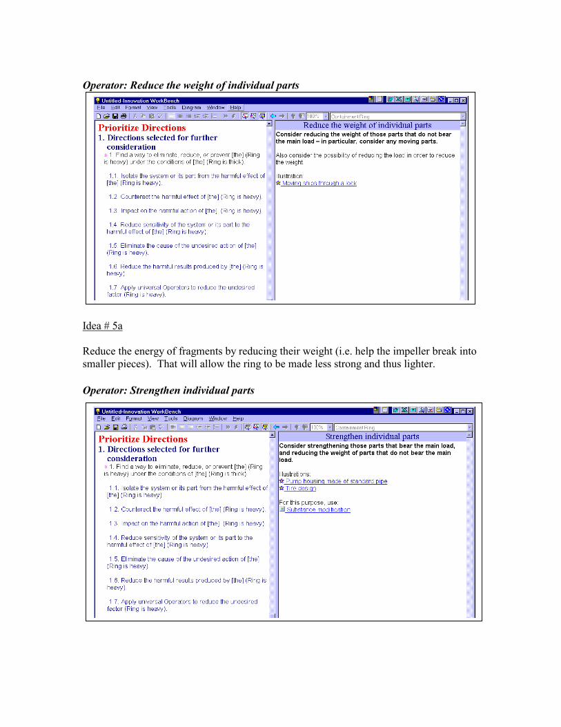
Operator: Reduce the weight of individual parts Idea # 5a Reduce the energy of fragments by reducing their weight (i.e. help the impeller break into smaller pieces). That will allow the ring to be made less strong and thus lighter. Operator: Strengthen individual parts
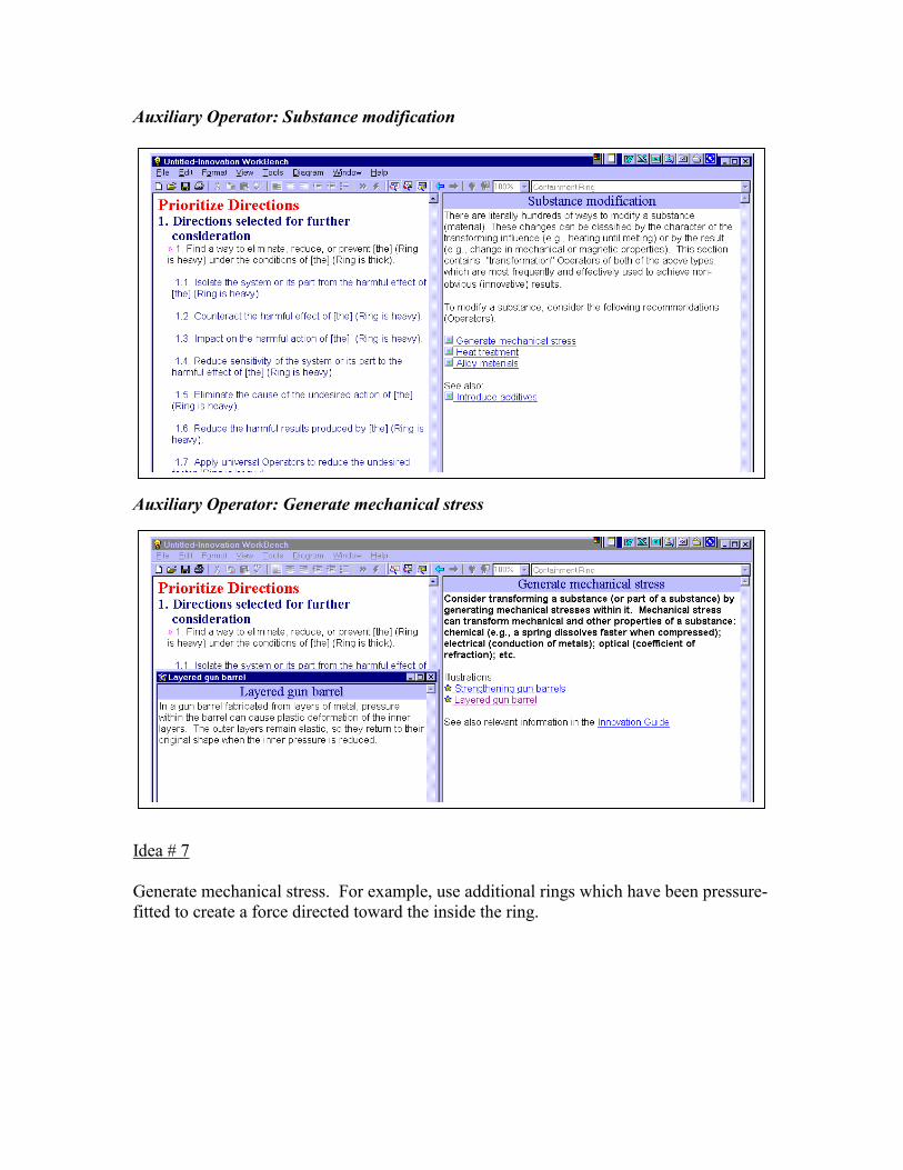
Auxiliary Operator: Substance modification Auxiliary Operator: Generate mechanical stress Idea # 7 Generate mechanical stress. For example, use additional rings which have been pressure-fitted to create a force directed toward the inside the ring.
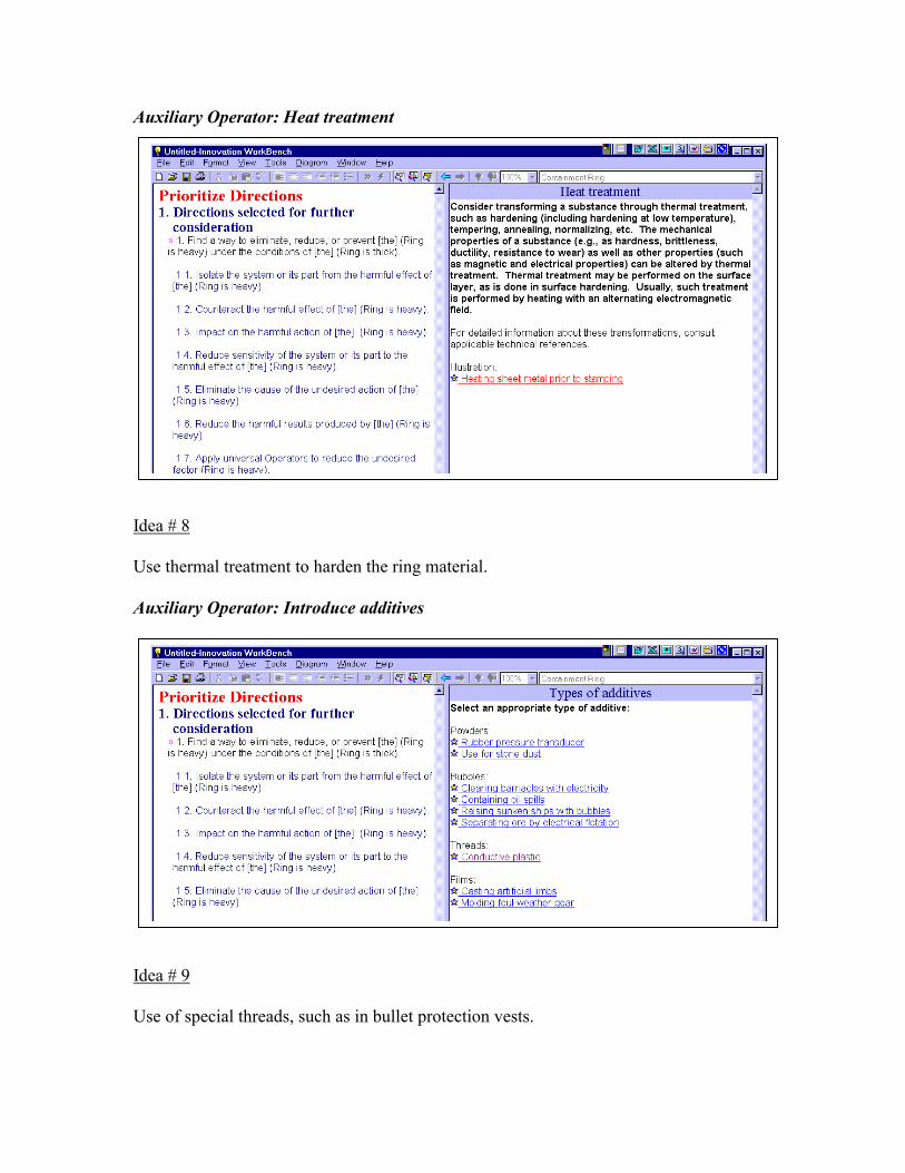
Auxiliary Operator: Heat treatment Idea # 8 Use thermal treatment to harden the ring material. Auxiliary Operator: Introduce additives Idea # 9 Use of special threads, such as in bullet protection vests.
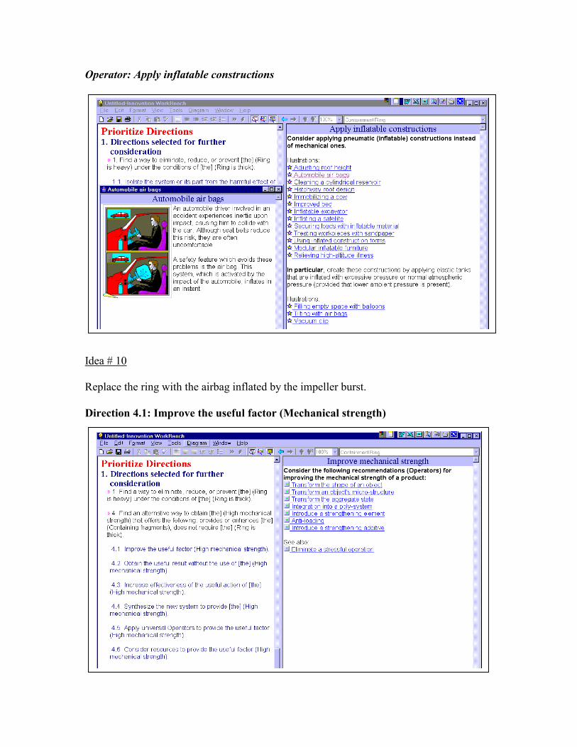
Operator: Apply inflatable constructions Idea # 10 Replace the ring with the airbag inflated by the impeller burst. Direction 4.1: Improve the useful factor (Mechanical strength)
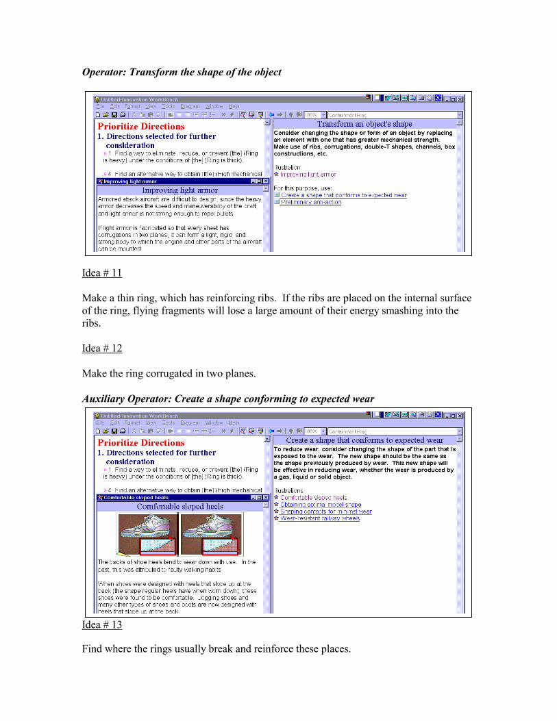
Operator: Transform the shape of the object Idea # 11 Make a thin ring, which has reinforcing ribs. If the ribs are placed on the internal surface of the ring, flying fragments will lose a large amount of their energy smashing into the ribs. Idea # 12 Make the ring corrugated in two planes. Auxiliary Operator: Create a shape conforming to expected wear Idea # 13 Find where the rings usually break and reinforce these places.
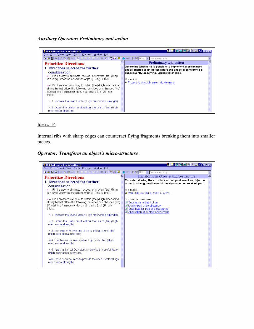
Auxiliary Operator: Preliminary anti-action Idea # 14 Internal ribs with sharp edges can counteract flying fragments breaking them into smaller pieces. Operator: Transform an object's micro-structure
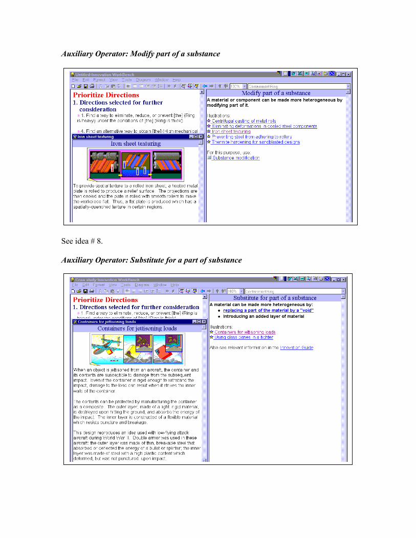
Auxiliary Operator: Modify part of a substance See idea # 8. Auxiliary Operator: Substitute for a part of substance
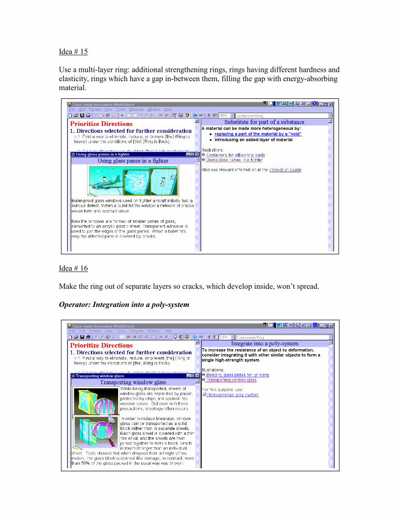
Idea # 15 Use a multi-layer ring: additional strengthening rings, rings having different hardness and elasticity, rings which have a gap in-between them, filling the gap with energy-absorbing material. Idea # 16 Make the ring out of separate layers so cracks, which develop inside, won’t spread. Operator: Integration into a poly-system
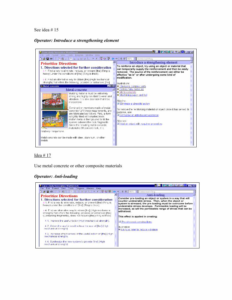
See idea # 15 Operator: Introduce a strengthening element Idea # 17 Use metal concrete or other composite materials Operator: Anti-loading
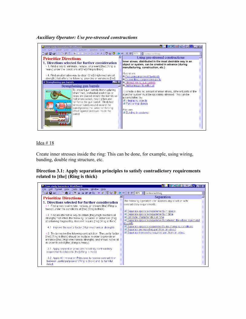
Auxiliary Operator: Use pre-stressed constructions Idea # 18 Create inner stresses inside the ring: This can be done, for example, using wiring, banding, double ring structure, etc. Direction 3.1: Apply separation principles to satisfy contradictory requirements related to [the] (Ring is thick)
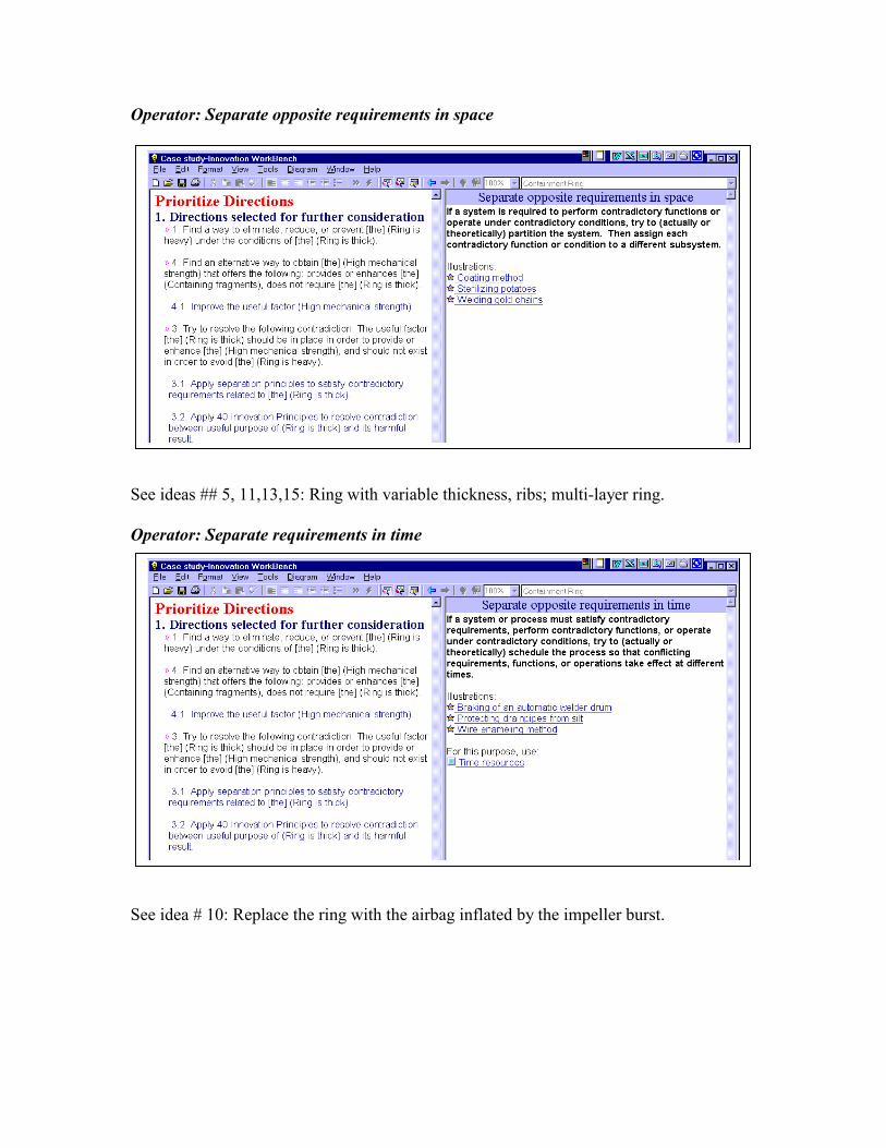
Operator: Separate opposite requirements in space See ideas ## 5, 11,13,15: Ring with variable thickness, ribs; multi-layer ring. Operator: Separate requirements in time See idea # 10: Replace the ring with the airbag inflated by the impeller burst.
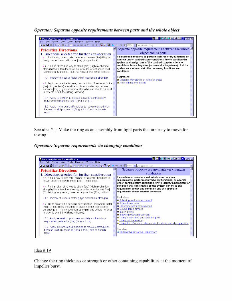
Operator: Separate opposite requirements between parts and the whole object See idea # 1: Make the ring as an assembly from light parts that are easy to move for testing. Operator: Separate requirements via changing conditions Idea # 19 Change the ring thickness or strength or other containing capabilities at the moment of impeller burst.
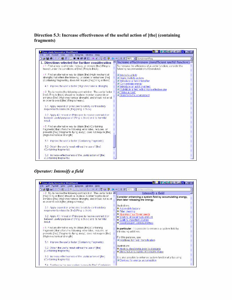
Direction 5.3: Increase effectiveness of the useful action of [the] (containing fragments) Operator: Intensify a field
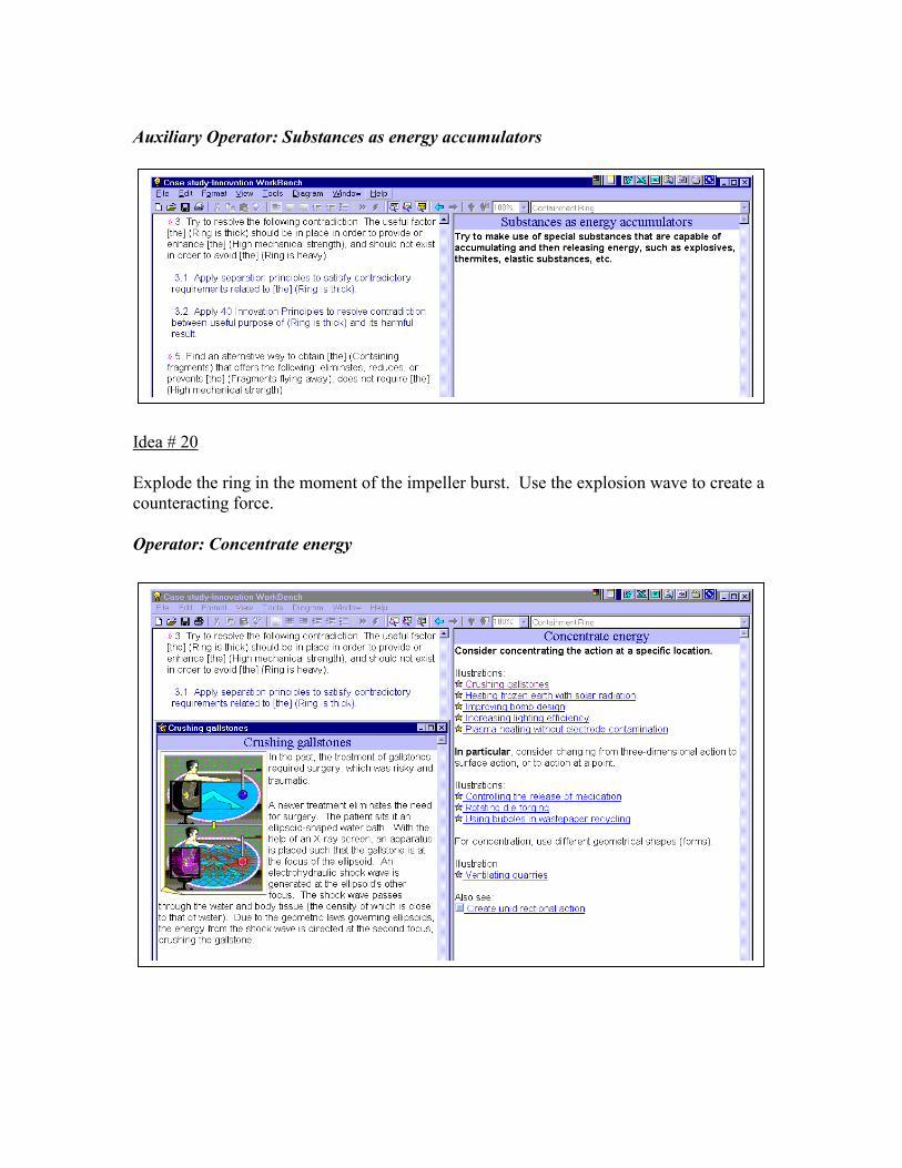
Auxiliary Operator: Substances as energy accumulators Idea # 20 Explode the ring in the moment of the impeller burst. Use the explosion wave to create a counteracting force. Operator: Concentrate energy
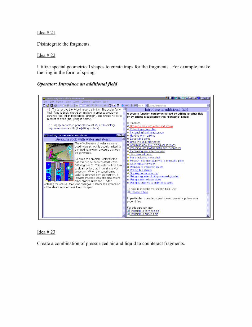
Idea # 21 Disintegrate the fragments. Idea # 22 Utilize special geometrical shapes to create traps for the fragments. For example, make the ring in the form of spring. Operator: Introduce an additional field
A system function may be enhanced by adding another field or a substance with a field.
Idea # 23 Create a combination of pressurized air and liquid to counteract fragments.
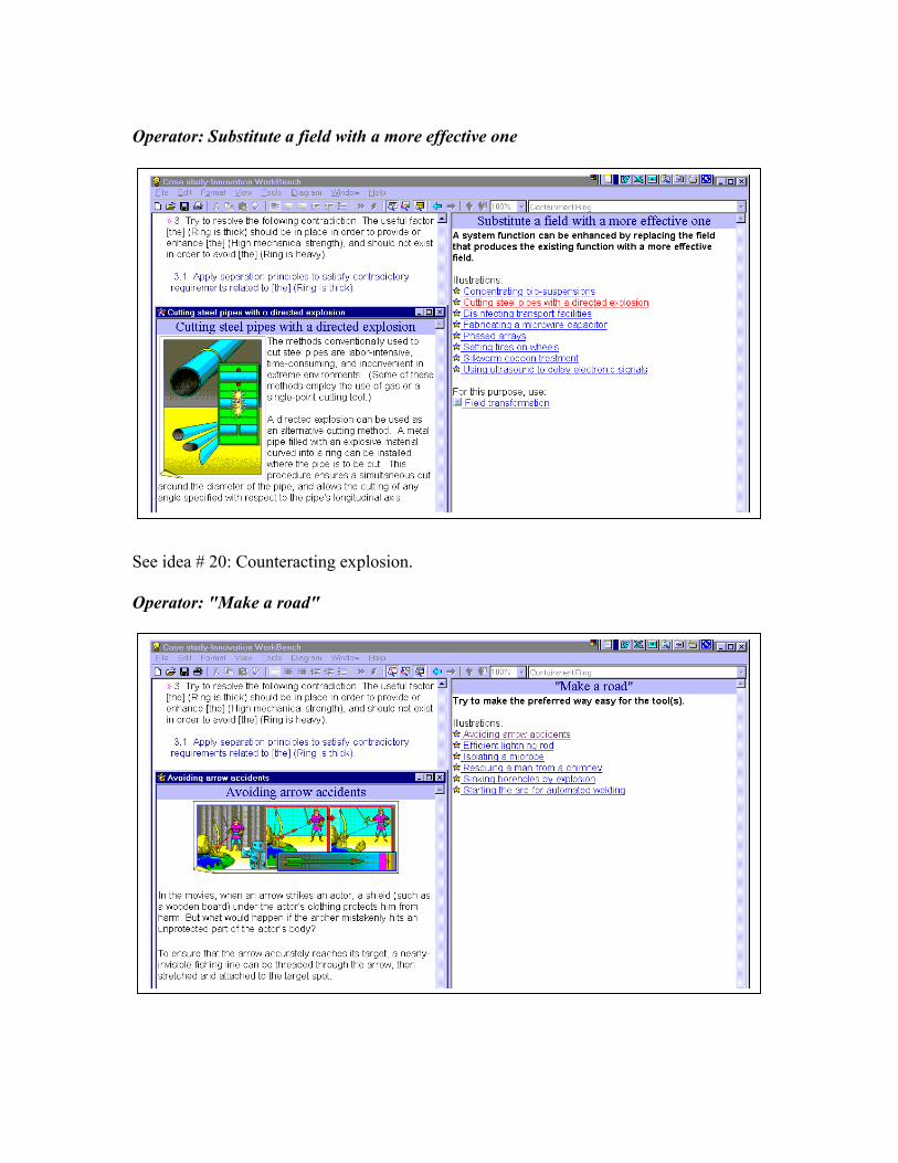
Operator: Substitute a field with a more effective one See idea # 20: Counteracting explosion. Operator: "Make a road"
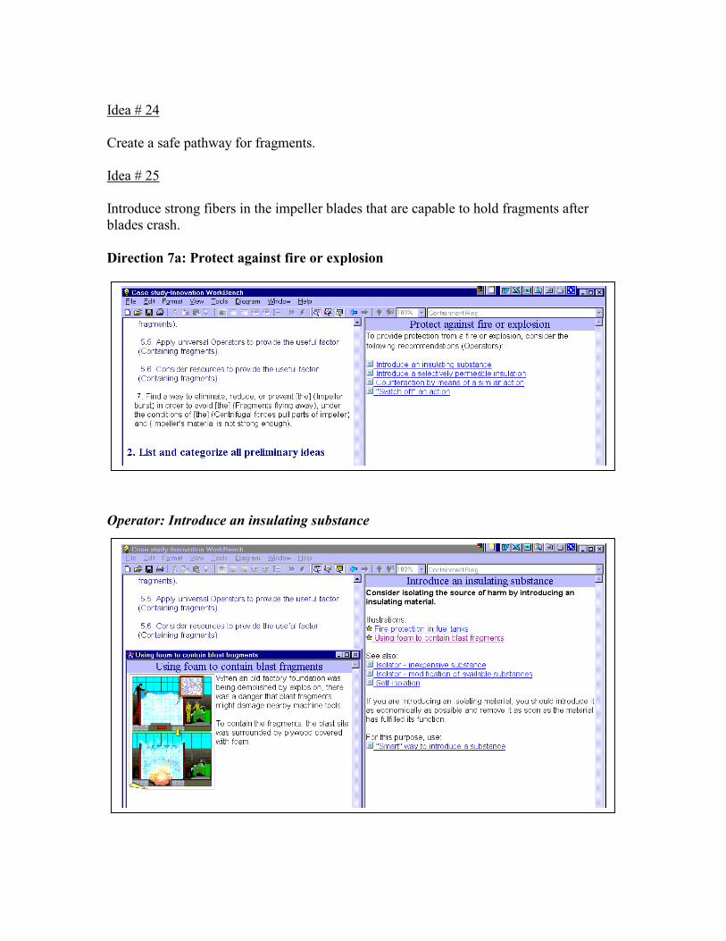
Idea # 24 Create a safe pathway for fragments. Idea # 25 Introduce strong fibers in the impeller blades that are capable to hold fragments after blades crash. Direction 7a: Protect against fire or explosion Operator: Introduce an insulating substance
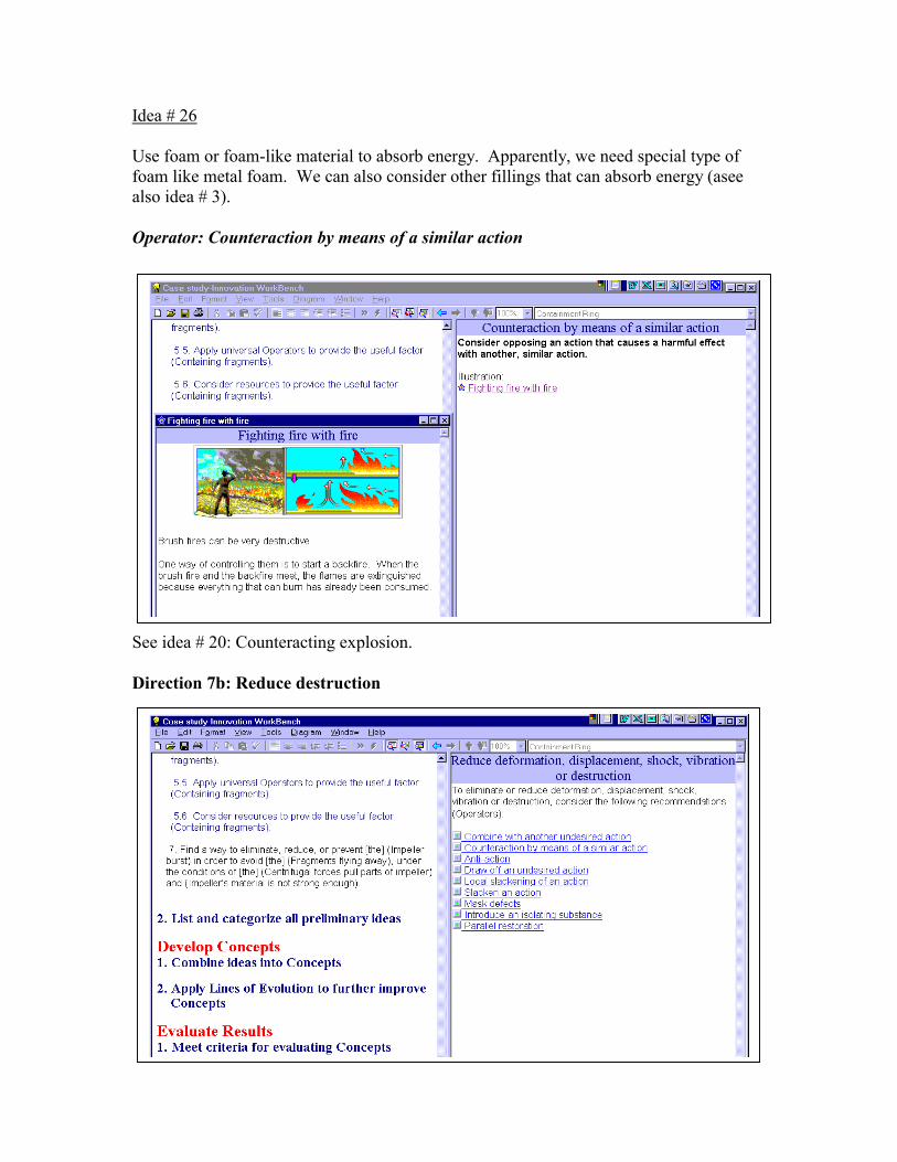
Idea # 26 Use foam or foam-like material to absorb energy. Apparently, we need special type of foam like metal foam. We can also consider other fillings that can absorb energy (asee also idea # 3). Operator: Counteraction by means of a similar action See idea # 20: Counteracting explosion. Direction 7b: Reduce destruction
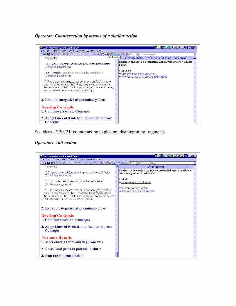
Operator: Counteraction by means of a similar action See ideas ## 20, 21: counteracting explosion, disintegrating fragments Operator: Anti-action
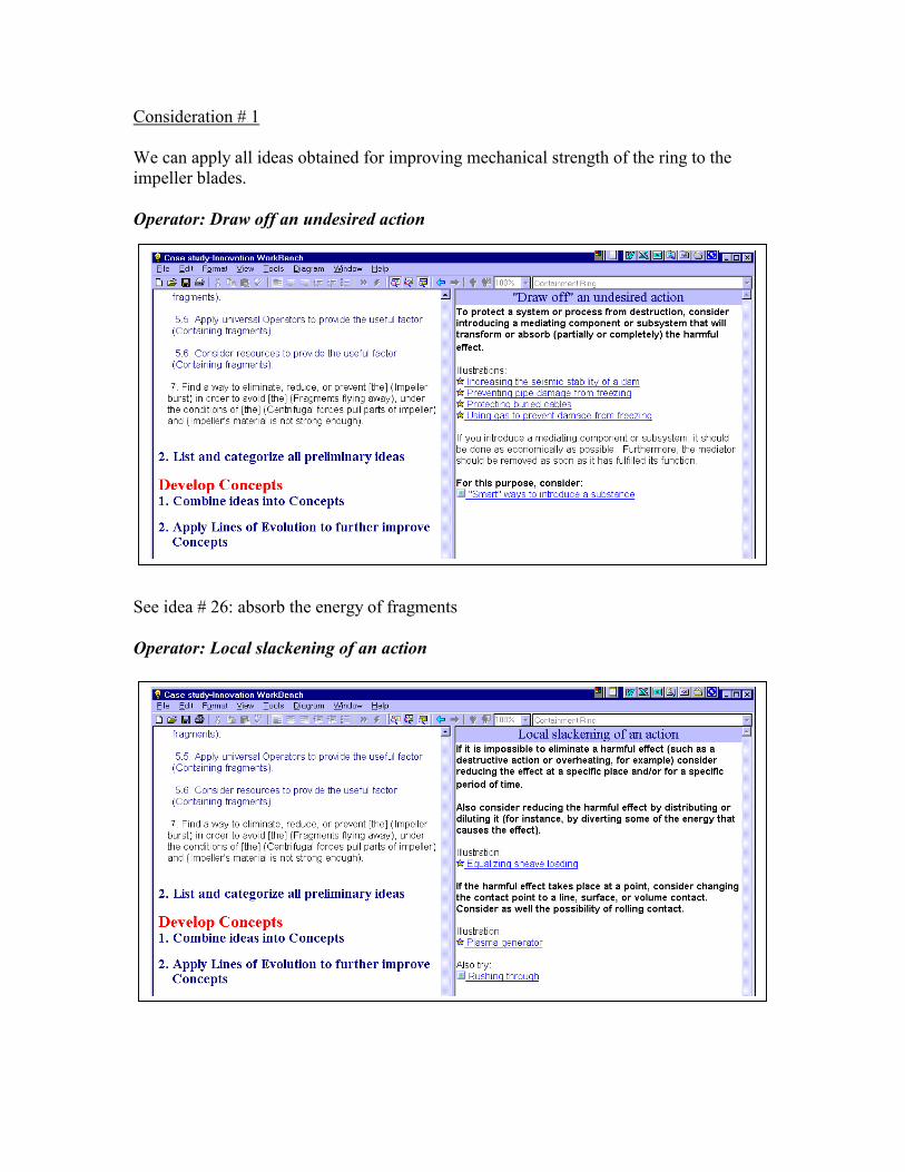
Consideration # 1 We can apply all ideas obtained for improving mechanical strength of the ring to the impeller blades. Operator: Draw off an undesired action See idea # 26: absorb the energy of fragments Operator: Local slackening of an action

Idea # 27 Define less dangerous directions and redirect fragments to these directions. Idea # 28 Distributing the harmful energy between more fragments (see also ideas # 7 and 21: reducing energy /mass of fragments) Operator: Slacken an action (Weaken an undesired action by prolonging it) Idea # 29 Create a special pathway (spiral) to trap the fragments and to reduce their energy while traveling through the spiral route (see ideas ## 22 and 24). Also, see idea # 26: absorb the energy.
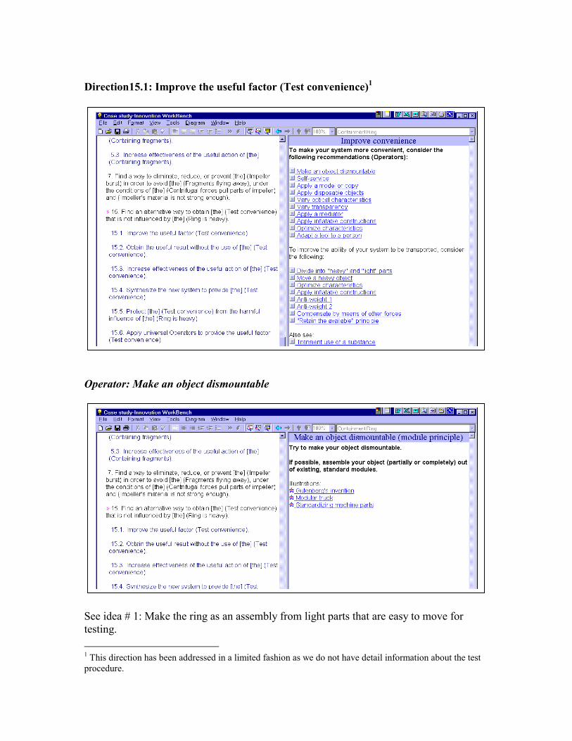
Direction15.1: Improve the useful factor (Test convenience)1 Operator: Make an object dismountable See idea # 1: Make the ring as an assembly from light parts that are easy to move for testing. 1 This direction has been addressed in a limited fashion as we do not have detail information about the test procedure.
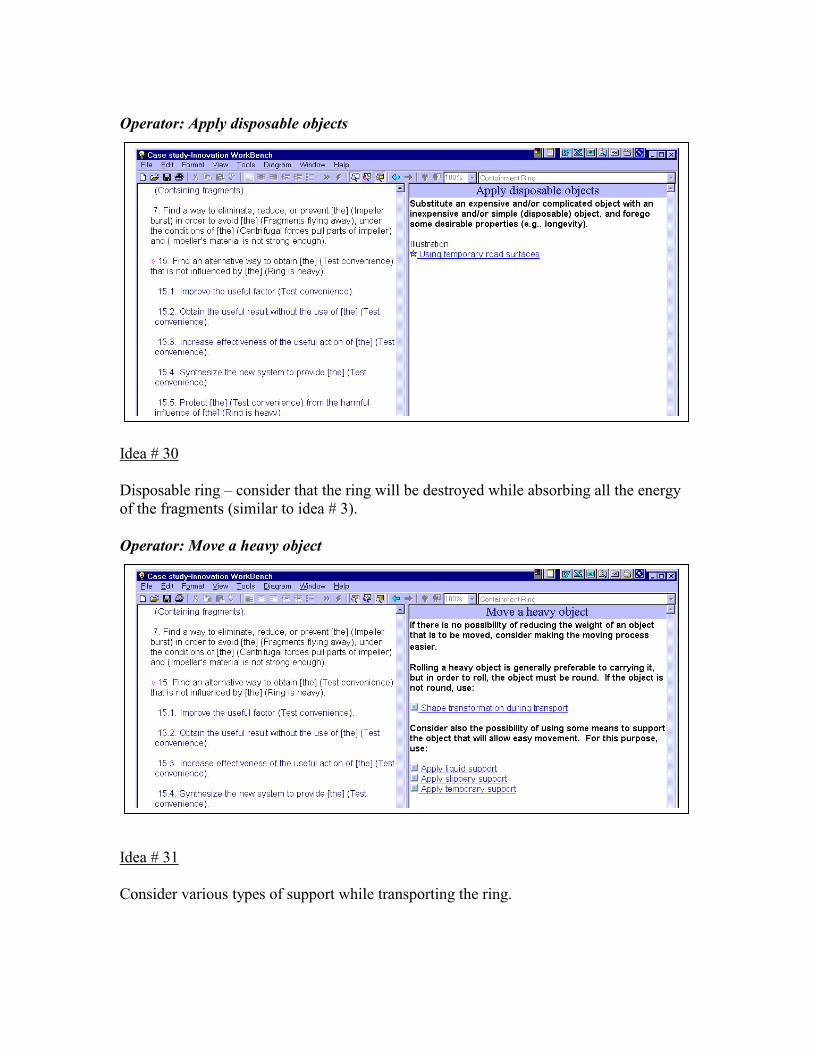
Operator: Apply disposable objects Idea # 30 Disposable ring – consider that the ring will be destroyed while absorbing all the energy of the fragments (similar to idea # 3). Operator: Move a heavy object Idea # 31 Consider various types of support while transporting the ring.
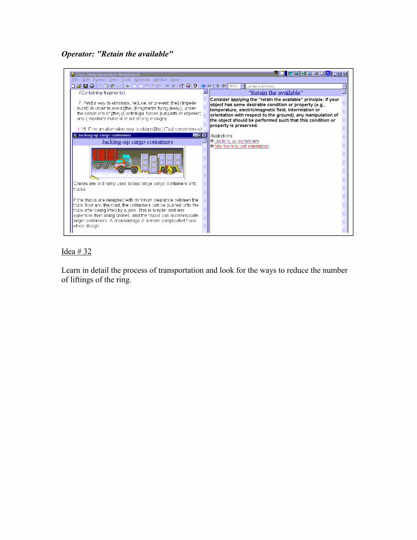
Operator: "Retain the available" Idea # 32 Learn in detail the process of transportation and look for the ways to reduce the number of liftings of the ring.

List and categorize all preliminary ideas Idea # 1: Make the ring as an assembly made of light-weight parts that are easy to move for testing purposes. Idea # 2: Provide high airflow with low rotational speed of the fan. Perhaps utilize several slow fans instead of one that rotates quickly. Idea # 3: Utilize a "weak" ring that will absorb energy as it is destroyed. Idea # 4: Perform testing without removing the ring. Idea # 5: Reduce the mass of the fragments to reduce damage. Idea # 6: Vary the thickness of the ring tube, reducing the thickness where permissible. Idea # 7: Introduce preliminary stress. For example, use additional rings which have been pressure-fitted to create a force directed toward the inside of the ring. Idea # 8: Use thermal treatment to harden the ring material. Idea # 9: Use special reinforcing threads (fibers) such as those found in bullet-proof vests. Idea # 10: Replace the ring with an airbag that inflates when the impeller bursts. Idea # 11. Make a thin ring that has reinforcing ribs. If the ribs are placed on the internal surface of the ring, flying fragments will lose much of their energy smashing into the ribs. Idea # 12: Make the ring corrugated in two planes. Idea # 13: Determine where the ring usually breaks and reinforce those places. Idea # 14: Internal ribs with sharp edges can counteract flying fragments, breaking them into smaller pieces. Idea # 15: Use a multi-layer ring: additional strengthening rings, rings having different hardness and elasticity, rings which have a gap in between them, filling the gap with an energy-absorbing material. Idea # 16: Make the ring out of separate layers so that if cracks develop inside they will not spread. Idea # 17: Use metal-concrete or some other composite material.

Idea # 18: Create inner stresses inside the ring: This can be done using wiring, banding, double ring structure, etc. Idea # 19. Change the ring thickness or strength or other containment capabilities the moment the impeller bursts. Idea # 20. Explode the ring the moment the impeller bursts. Use the explosion wave to create a counteracting force. Idea # 21. Disintegrate the fragments. Idea # 22. Utilize special geometrical shapes to create traps for the fragments. For example, make the ring in the form of spring. Idea # 23. Create a combination of pressurized air and liquid to counteract the fragments. Idea # 24: Create a safe pathway for the fragments. Idea # 25. Introduce strong fibers in the impeller blades that are capable of holding the fragments after the impeller bursts. Idea # 26. Use foam or foam-like material to absorb energy. Apparently, we need a special type of foam such as metal foam. We can also consider other fillings that can absorb energy (see idea # 3). Idea # 27. Define the least dangerous directions and redirect the fragments in these directions. Idea # 28. Distribute the harmful energy between more of the fragments (see also ideas # 7 and 21: reducing energy/mass of the fragments). Idea # 29. Create a special pathway (spiral) to trap the fragments and to reduce their energy while traveling through the spiral route (see ideas # 22 and 24). Also, see idea # 26: absorb the energy. Idea # 30. Disposable ring – consider that the ring will be destroyed while absorbing all the energy of the fragments (similar to idea # 3). Idea # 31. Consider various types of support while transporting the ring. Idea # 32. Learn the details of the transporting process and look for the ways to reduce the number of liftings.

We can categorized the obtained ideas into the following groups: 1. Strengthening the ring via a) changing the ring material structure: • creating inner stresses (wiring, banding, press-fit) (#18, 7) • introducing special reinforcing threads (fibers), using metal-concrete or other
composite materials (# 9, 17, 25) • special thermal treatment for hardening the ring material (# 8) • using a multi-layer ring with layers with different properties (elasticity, hardness,
gaps filled with energy-absorbing materials) (# 15) b) changing the ring’s shape: • vary the ring thickness to best accommodate the situation (# 6,13) • create various reinforcing ribs (# 11) • use two-plane corrugations (# 12) 2. Increasing the ring’s energy-absorbing properties via a) changing the material structure: • using foam and/or foam-like materials (metal foam, honeycomb, wiring, brushes) (#3,
23, 26, 30) • using a multi-layer ring with layers capable of moving relative to one another to
absorb extra energy b) changing the ring’s shape: • spiral or other traps that can slow down the fragments (#22) 3. Reducing the mass/energy of the flying fragments to reduce damage and allow the ring’s mechanical strength to be lowered via • changing the ring’s material structure to make it capable of breaking into smaller
pieces (# 5, 21,28) • introduce ribs with sharp edges capable of breaking fragments into smaller pieces (#
11,14) 4. Improve testing convenience, including: • perform the test without removing the ring (# 4) • make the ring dismountable and transport parts of the ring rather than the whole thing
(# 1) • consider various types of special support during ring transport (# 31)

5. Strengthen the impeller blades to eliminate the need for the ring (#25) 6. Define or create a safe pathway for the fragments (# 24, 27, 29) 7. Change the principle of operation of the ring, including: • replace the ring with an airbag that inflates the moment the impeller bursts (# 10) or
change its thickness (# 19) • explode the ring to create a counteracting force (# 20) and/or break the fragments into
smaller pieces 8. Replace the impeller with a safer method of providing air (# 2)
Develop Concepts
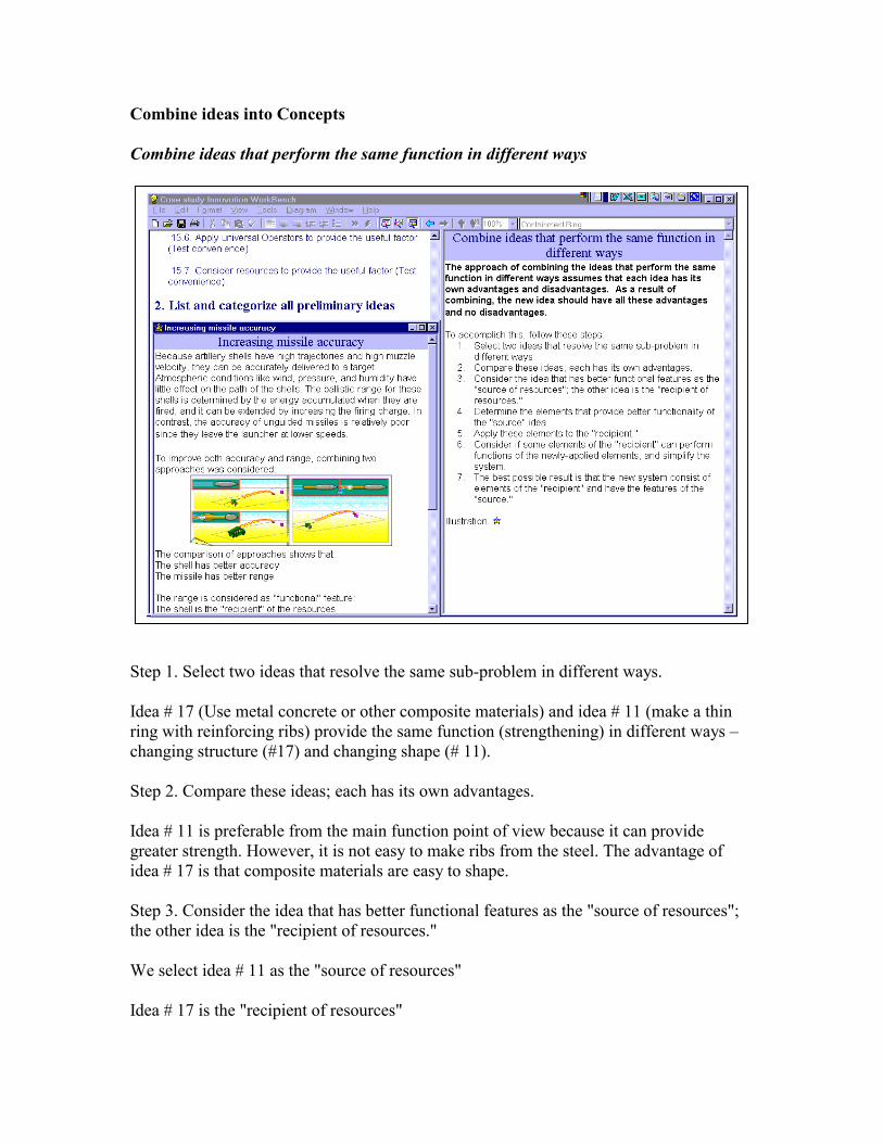
Combine ideas into Concepts Combine ideas that perform the same function in different ways Step 1. Select two ideas that resolve the same sub-problem in different ways. Idea # 17 (Use metal concrete or other composite materials) and idea # 11 (make a thin ring with reinforcing ribs) provide the same function (strengthening) in different ways – changing structure (#17) and changing shape (# 11). Step 2. Compare these ideas; each has its own advantages. Idea # 11 is preferable from the main function point of view because it can provide greater strength. However, it is not easy to make ribs from the steel. The advantage of idea # 17 is that composite materials are easy to shape. Step 3. Consider the idea that has better functional features as the "source of resources"; the other idea is the "recipient of resources." We select idea # 11 as the "source of resources" Idea # 17 is the "recipient of resources"
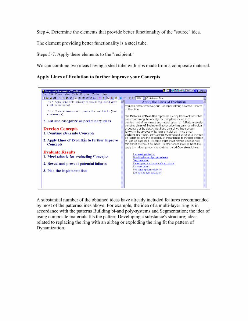
Step 4. Determine the elements that provide better functionality of the "source" idea. The element providing better functionality is a steel tube. Steps 5-7. Apply these elements to the "recipient." We can combine two ideas having a steel tube with ribs made from a composite material. Apply Lines of Evolution to further improve your Concepts A substantial number of the obtained ideas have already included features recommended by most of the patterns/lines above. For example, the idea of a multi-layer ring is in accordance with the patterns Building bi-and poly-systems and Segmentation; the idea of using composite materials fits the pattern Developing a substance's structure; ideas related to replacing the ring with an airbag or exploding the ring fit the pattern of Dynamization.

It might still be interesting, however, to consider the set of Operators/Lines entitled Increasing controllability. Operator: Introduce an additive to increase process controllability
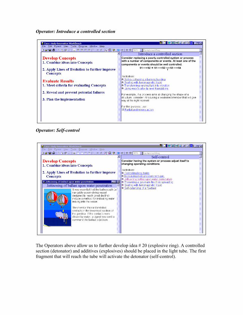
Operator: Introduce a controlled section Operator: Self-control The Operators above allow us to further develop idea # 20 (explosive ring). A controlled section (detonator) and additives (explosives) should be placed in the light tube. The first fragment that will reach the tube will activate the detonator (self-control).
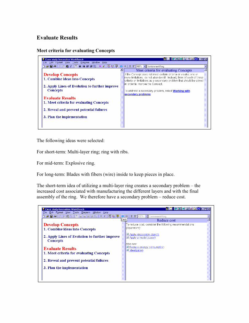
Evaluate Results Meet criteria for evaluating Concepts The following ideas were selected: For short-term: Multi-layer ring; ring with ribs. For mid-term: Explosive ring. For long-term: Blades with fibers (wire) inside to keep pieces in place. The short-term idea of utilizing a multi-layer ring creates a secondary problem – the increased cost associated with manufacturing the different layers and with the final assembly of the ring. We therefore have a secondary problem – reduce cost.
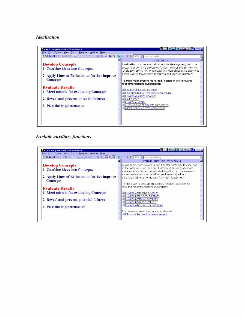
Idealization Exclude auxiliary functions
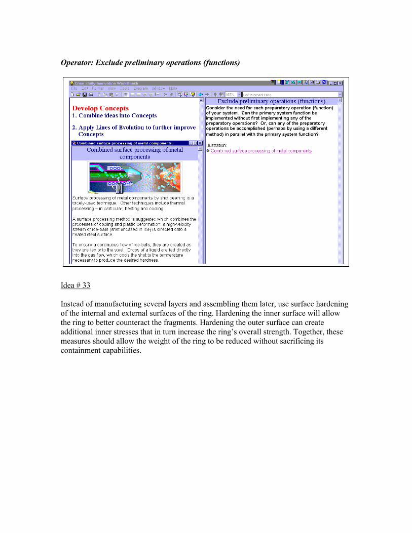
Operator: Exclude preliminary operations (functions) Idea # 33 Instead of manufacturing several layers and assembling them later, use surface hardening of the internal and external surfaces of the ring. Hardening the inner surface will allow the ring to better counteract the fragments. Hardening the outer surface can create additional inner stresses that in turn increase the ring’s overall strength. Together, these measures should allow the weight of the ring to be reduced without sacrificing its containment capabilities.
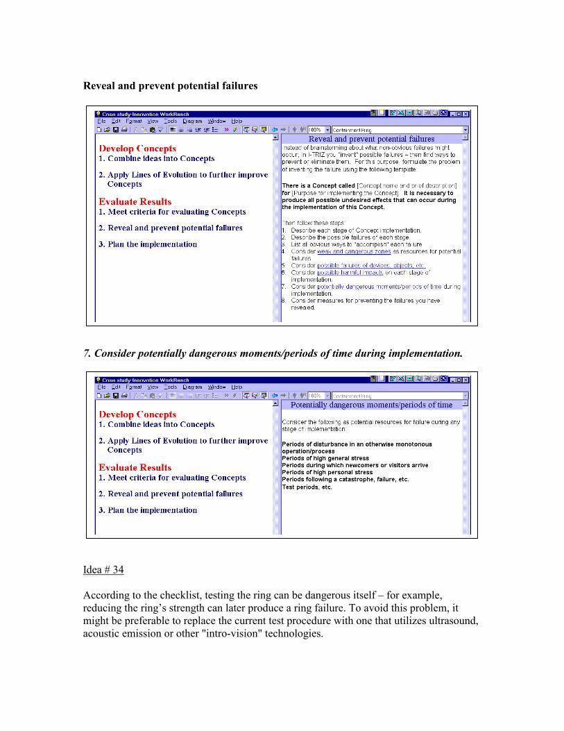
Reveal and prevent potential failures 7. Consider potentially dangerous moments/periods of time during implementation. Idea # 34 According to the checklist, testing the ring can be dangerous itself – for example, reducing the ring’s strength can later produce a ring failure. To avoid this problem, it might be preferable to replace the current test procedure with one that utilizes ultrasound, acoustic emission or other "intro-vision" technologies.

Plan the implementation The following ideas were suggested for testing: For the short-term: Ring with hardened surfaces; ring with ribs. For the mid-term: Explosive ring. For the long-term: Blades with fibers (wire) inside to keep the fragments in place.
Summary
Tool utilized Category Contradictio
n Table Ideation
Improver Ideation
IWB IMC Tech Optimizer2
Number of Directions (problem statements) offered
3 6 18
Number of recommendations (Operators) offered
11 44 >100 + >10 groups
Number of ideas obtained 6 19 34
2 The column will be filled out in the next issue.

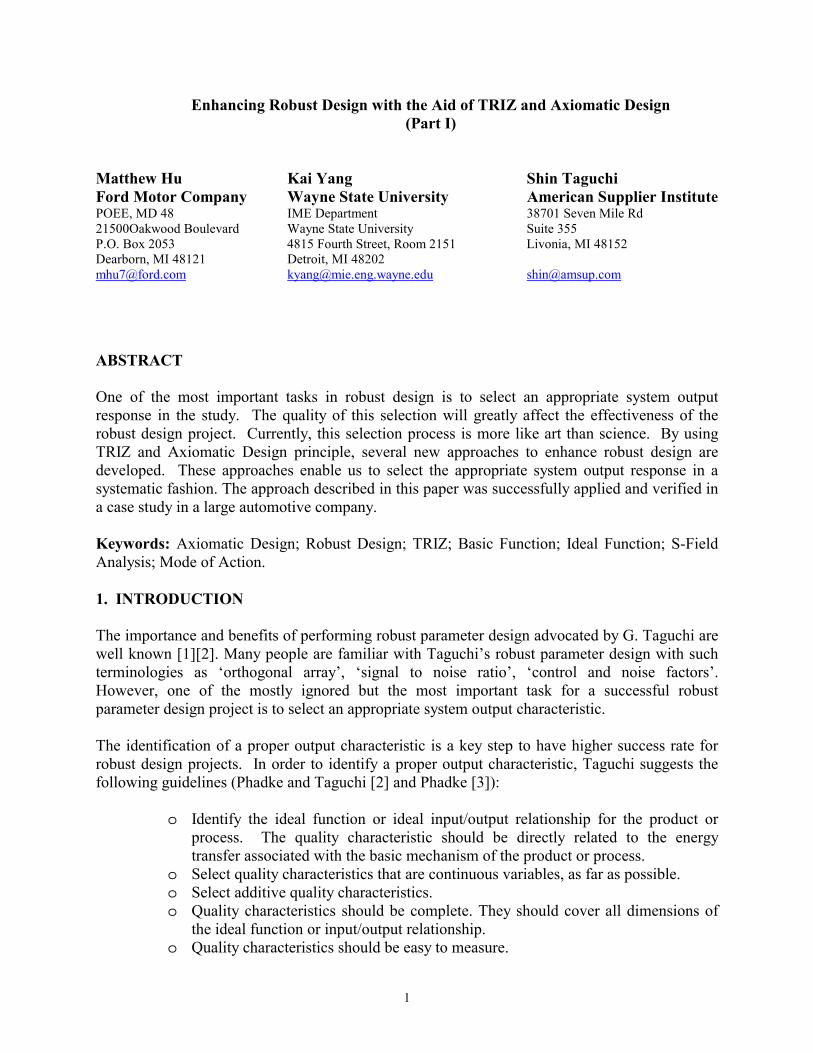
1
Enhancing Robust Design with the Aid of TRIZ and Axiomatic Design (Part I)
Matthew Hu Kai Yang Shin Taguchi Ford Motor Company Wayne State University American Supplier Institute POEE, MD 48 IME Department 38701 Seven Mile Rd 21500Oakwood Boulevard Wayne State University Suite 355 P.O. Box 2053 4815 Fourth Street, Room 2151 Livonia, MI 48152 Dearborn, MI 48121 Detroit, MI 48202 [email protected] [email protected] [email protected] ABSTRACT One of the most important tasks in robust design is to select an appropriate system output response in the study. The quality of this selection will greatly affect the effectiveness of the robust design project. Currently, this selection process is more like art than science. By using TRIZ and Axiomatic Design principle, several new approaches to enhance robust design are developed. These approaches enable us to select the appropriate system output response in a systematic fashion. The approach described in this paper was successfully applied and verified in a case study in a large automotive company. Keywords: Axiomatic Design; Robust Design; TRIZ; Basic Function; Ideal Function; S-Field Analysis; Mode of Action. 1. INTRODUCTION The importance and benefits of performing robust parameter design advocated by G. Taguchi are well known [1][2]. Many people are familiar with Taguchi’s robust parameter design with such terminologies as ‘orthogonal array’, ‘signal to noise ratio’, ‘control and noise factors’. However, one of the mostly ignored but the most important task for a successful robust parameter design project is to select an appropriate system output characteristic. The identification of a proper output characteristic is a key step to have higher success rate for robust design projects. In order to identify a proper output characteristic, Taguchi suggests the following guidelines (Phadke and Taguchi [2] and Phadke [3]):
o Identify the ideal function or ideal input/output relationship for the product or process. The quality characteristic should be directly related to the energy transfer associated with the basic mechanism of the product or process.
o Select quality characteristics that are continuous variables, as far as possible. o Select additive quality characteristics. o Quality characteristics should be complete. They should cover all dimensions of
the ideal function or input/output relationship. o Quality characteristics should be easy to measure.
2
According to Taguchi, it is important to avoid using ‘quality symptoms’ such as reliability data, warranty information, scrap and % defective in the late of product development cycle and manufacturing environment, as the output characteristic. Since improving a ‘symptom’ may not be helpful in improving the robustness of system’s ability to deliver its functions, which is really the key objective of a robust design project. Understanding system function, especially basic function, is the key for robust technology development [1]. Defining the ideal state of the basic function, called ideal function, is the centerpiece for identifying output characteristic. The reason for using an energy-related system output response, according to the discussion of Pahl & Beitz [8] and Hubka [9], is due to the fact that an engineering system is always designed for delivering its basic function. To deliver its basic function, at least one of the three types of transformation, material, energy and signal transformation (Figure 1) must be used.
Where the details of energy, material and signal include:
• Energy: mechanical, thermal, electrical, chemical… also force, current, heat…
• Material: liquid, gas… also raw material, end product, component… • Signal: information, data, display, magnitude…
For example, a machining process as an engineering system, the ideal relationship between output and input should be that the output dimensions are exactly same as the intended dimension. This kind of the transformation system is the material transformation. Since energy transformation is a very important type of transformation, and there are many similarities in using these three types of transformation to identify the appropriate output characteristic. Without loss of generality, energy transformations are used as examples throughout in this paper. Some of the published literature and articles pointed out that energy related characteristic is very helpful to identify proper quality characteristic and should be considered. Nair [4] cites Phadke's discussion, finding system output response that meets all of these guidelines is sometimes difficult or simply not possible with the technical know-how of the engineers involved. In general, it will be quite challenging to identify system output responses which will meet all of these criteria. Taguchi acknowledges this for fact and states that the use of Taguchi methods will be inefficient to the certain extent if these guidelines are not satisfied. Revelle, Moran and Cox [5] cites Shin Taguchi, Verdun and Wu's work and point out that the selection of system output
Technical System
Energy Material
Signal
Energy Material Signal
Figure 1. Technical System: The conversion of energy, material and signals
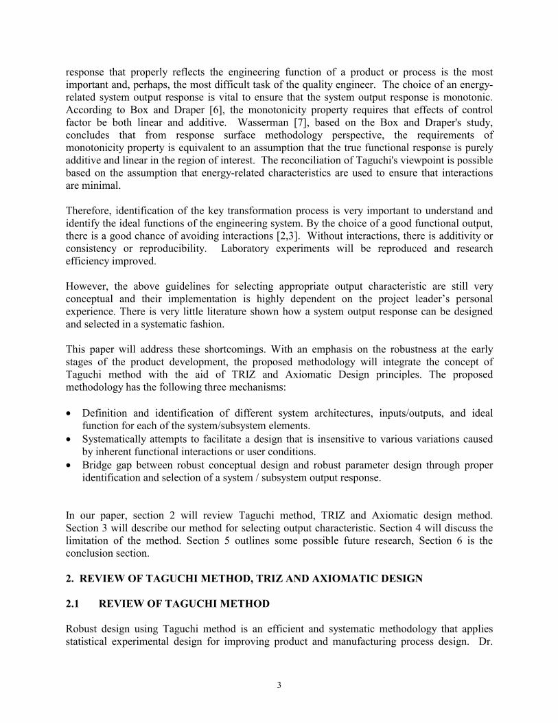
3
response that properly reflects the engineering function of a product or process is the most important and, perhaps, the most difficult task of the quality engineer. The choice of an energy-related system output response is vital to ensure that the system output response is monotonic. According to Box and Draper [6], the monotonicity property requires that effects of control factor be both linear and additive. Wasserman [7], based on the Box and Draper's study, concludes that from response surface methodology perspective, the requirements of monotonicity property is equivalent to an assumption that the true functional response is purely additive and linear in the region of interest. The reconciliation of Taguchi's viewpoint is possible based on the assumption that energy-related characteristics are used to ensure that interactions are minimal. Therefore, identification of the key transformation process is very important to understand and identify the ideal functions of the engineering system. By the choice of a good functional output, there is a good chance of avoiding interactions [2,3]. Without interactions, there is additivity or consistency or reproducibility. Laboratory experiments will be reproduced and research efficiency improved. However, the above guidelines for selecting appropriate output characteristic are still very conceptual and their implementation is highly dependent on the project leader’s personal experience. There is very little literature shown how a system output response can be designed and selected in a systematic fashion. This paper will address these shortcomings. With an emphasis on the robustness at the early stages of the product development, the proposed methodology will integrate the concept of Taguchi method with the aid of TRIZ and Axiomatic Design principles. The proposed methodology has the following three mechanisms: • Definition and identification of different system architectures, inputs/outputs, and ideal
function for each of the system/subsystem elements. • Systematically attempts to facilitate a design that is insensitive to various variations caused
by inherent functional interactions or user conditions. • Bridge gap between robust conceptual design and robust parameter design through proper
identification and selection of a system / subsystem output response. In our paper, section 2 will review Taguchi method, TRIZ and Axiomatic design method. Section 3 will describe our method for selecting output characteristic. Section 4 will discuss the limitation of the method. Section 5 outlines some possible future research, Section 6 is the conclusion section.
2. REVIEW OF TAGUCHI METHOD, TRIZ AND AXIOMATIC DESIGN 2.1 REVIEW OF TAGUCHI METHOD
Robust design using Taguchi method is an efficient and systematic methodology that applies statistical experimental design for improving product and manufacturing process design. Dr.
4
Genichi Taguchi’s development of robust design is a great engineering achievement (Clausing 1998) [10]. By 1990, concurrent engineering was becoming widespread in American industry. It brought great improvements. However, the pioneers such as Ford and Xerox were realizing that more was needed. Especially robust design needed to be practiced widely throughout the development of new products and processes. Taguchi essentially uses the conventional statistical tools, but he simplifies them by identifying a set of stringent guidelines with energy transformation model focused engineering system for experiment layout and analysis of results. Taguchi used and promoted statistical techniques for quality from an engineer’s perspective rather than that of a statistician. As Taguchi’s ideas become more widespread, more and more design engineers use Taguchi’s methodology in their everyday lives. Due to the growing popularity of robust design methods, more and more quality and engineering professionals have shifted their quality paradigm from defect inspecting and problem solving to designing quality and reliability into products or processes. Taguchi's approach to design emphasizes continuous improvement and encompasses different aspects of the design process grouped into three main stages:
1. System design. This broadly corresponds to conceptual design in the generalized model of the design process. System design is the conceptual design stage in which scientific and engineering expertise is applied to develop new and original technologies. Robust design using Taguchi method does not focus on the system design stage.
2. Parameter design. Parameter design is the stage at which a selected concept is optimized. Many variables can affect a system function. The variables need to be characterized from an engineering viewpoint. The goals of parameter design are to (1) find that combination of control factors settings that allow the system to achieve its ideal function and (2) remain insensitive to those variables that we cannot control. Parameter design provides opportunities to reduce the product and manufacturing costs.
3. Tolerance design. Although generally considered to be part of the detail design stage, Taguchi views this as a distinct stage to be used when sufficiently small variability cannot be achieved within a parameter design. Initially, tolerances are usually taken to be fairly wide because tight tolerances often incur high supplier or manufacturing costs. Tolerance design can be used to identify those tolerance that, when tightened, produce the most substantial improvement in performance.
Taguchi offers more than techniques of experimental design and analysis. He has a complete and integrated system to develop specifications, engineer the design to specifications, and manufacture the product to specifications. The essence of Taguchi’s approach to “quality by design” is this simple principle-instead of trying to eliminate or reduce the causes for product performance variability, adjust the design of the product so that it can be insensitive to the effects of uncontrolled (noise) variation. The losses incurred to society by the poor product design are quantified using what Taguchi calls ”loss function”, which are assumed to be quadratic in nature. The five principles of Taguchi’s methods are:
5
1. Select Proper System Output Response 2. Measurement of Function using S/N ratio 3. Take Advantage of Interactions between Control and Noise Factors 4. Use Orthogonal Arrays 5. Two-step Optimization
2.2 REVIEW OF TRIZ
TRIZ is a Russian acronym that stands for the Theory of Inventive Problem Solving originated by Genrikn Altshuller. How can the time required to invent be reduced? How can a process be structured to enhance breakthrough thinking? It was Altshuller's quest to facilitate the resolution of difficult inventive problems and pass the process for this facilitation on to other people. In trying to answer these questions, Altshuller realized how difficult it is for scientists to think outside their fields of reference, because that involves thinking with a different technology or "language". In the course of the study of some 400,000 inventions as depicted in patent descriptions, Altshuller noticed a fundamentally consistent approach used by the best inventors to solve problems. At the heart of the best solutions, as described by the patents, existed an engineering conflict, or a "contradiction." The best inventions consistently solved conflicts without compromise. Upon closer examination and classification of innovative solutions, natural patterns of solutions started to emerge. Altshuller had discovered that when an engineering system was reduced to reveal the essential system contradictions, inventive solutions eliminated the contradictions completely. Furthermore, Altshuller noticed that the same inventive solutions appeared repeatedly at different points in time and in different places. 2.2.1 SUBSTANCE FIELD ANALYSIS 1. Substance-field analysis is a TRIZ analytical tool for modeling problems related to
existing technological system. Substance-field is a model of minimal, functioning and controllable technical system [11]. Every system is created to perform some functions. The desired function is the output from an object or substance (S1), caused by another object (S2) with the help of some means (types of energy, F). The general term, substance has been used in the classical TRIZ literature to refer to some object. Substances are objects of any level of complexity. They can be single items or complex systems. The action or means of accomplishing the action is called a field. Within the database of patents, there are 76 standard substance-field solutions permit the quick modeling of simple structures for substance-field analysis. If there is a problem with an existing system and any of the three elements are missing, substance-field analysis indicates where the model requires completion and offers directions for innovative thinking. In short, substance-Field Analysis- S-F analysis is a technique used to model an engineering problem. S-F analysis looks at the interaction between substances and fields (energy) to describe the situation in a common language. In cases where the engineering system is not performing adequately, the S-F model leads the problem solver to standard
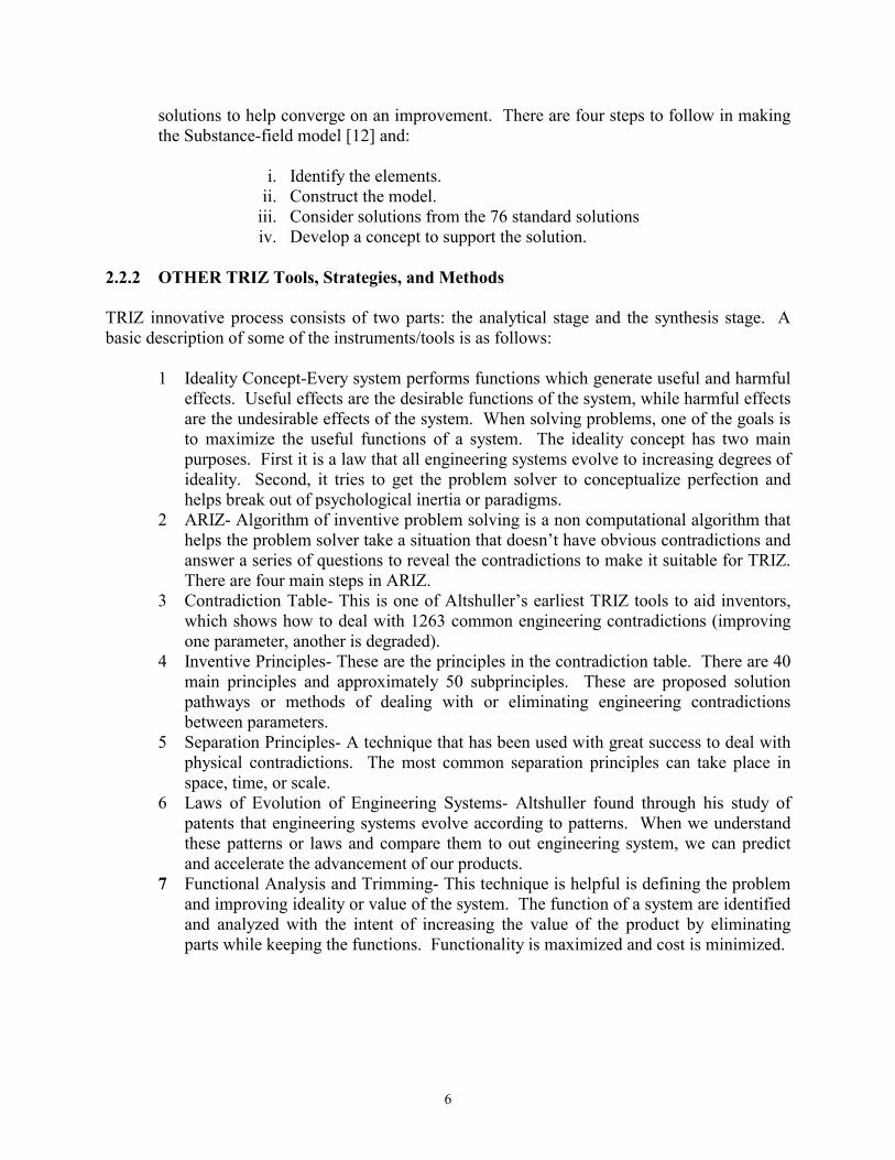
6
solutions to help converge on an improvement. There are four steps to follow in making the Substance-field model [12] and:
i. Identify the elements.
ii. Construct the model. iii. Consider solutions from the 76 standard solutions iv. Develop a concept to support the solution.
2.2.2 OTHER TRIZ Tools, Strategies, and Methods
TRIZ innovative process consists of two parts: the analytical stage and the synthesis stage. A basic description of some of the instruments/tools is as follows:
1 Ideality Concept-Every system performs functions which generate useful and harmful effects. Useful effects are the desirable functions of the system, while harmful effects are the undesirable effects of the system. When solving problems, one of the goals is to maximize the useful functions of a system. The ideality concept has two main purposes. First it is a law that all engineering systems evolve to increasing degrees of ideality. Second, it tries to get the problem solver to conceptualize perfection and helps break out of psychological inertia or paradigms.
2 ARIZ- Algorithm of inventive problem solving is a non computational algorithm that helps the problem solver take a situation that doesn’t have obvious contradictions and answer a series of questions to reveal the contradictions to make it suitable for TRIZ. There are four main steps in ARIZ.
3 Contradiction Table- This is one of Altshuller’s earliest TRIZ tools to aid inventors, which shows how to deal with 1263 common engineering contradictions (improving one parameter, another is degraded).
4 Inventive Principles- These are the principles in the contradiction table. There are 40 main principles and approximately 50 subprinciples. These are proposed solution pathways or methods of dealing with or eliminating engineering contradictions between parameters.
5 Separation Principles- A technique that has been used with great success to deal with physical contradictions. The most common separation principles can take place in space, time, or scale.
6 Laws of Evolution of Engineering Systems- Altshuller found through his study of patents that engineering systems evolve according to patterns. When we understand these patterns or laws and compare them to out engineering system, we can predict and accelerate the advancement of our products.
7 Functional Analysis and Trimming- This technique is helpful is defining the problem and improving ideality or value of the system. The function of a system are identified and analyzed with the intent of increasing the value of the product by eliminating parts while keeping the functions. Functionality is maximized and cost is minimized.
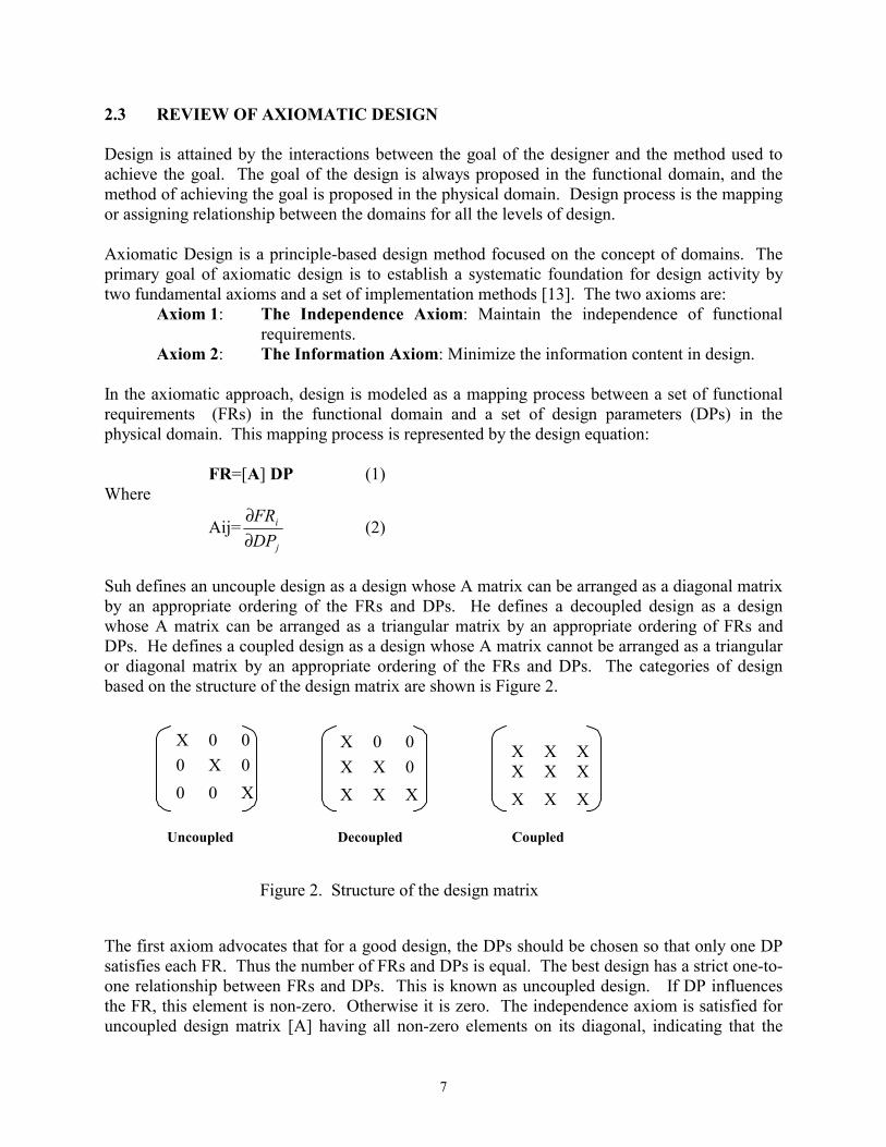
7
2.3 REVIEW OF AXIOMATIC DESIGN Design is attained by the interactions between the goal of the designer and the method used to achieve the goal. The goal of the design is always proposed in the functional domain, and the method of achieving the goal is proposed in the physical domain. Design process is the mapping or assigning relationship between the domains for all the levels of design. Axiomatic Design is a principle-based design method focused on the concept of domains. The primary goal of axiomatic design is to establish a systematic foundation for design activity by two fundamental axioms and a set of implementation methods [13]. The two axioms are:
Axiom 1: The Independence Axiom: Maintain the independence of functional requirements.
Axiom 2: The Information Axiom: Minimize the information content in design. In the axiomatic approach, design is modeled as a mapping process between a set of functional requirements (FRs) in the functional domain and a set of design parameters (DPs) in the physical domain. This mapping process is represented by the design equation: FR=[A] DP (1) Where
Aij=j
i
DPFR
∂∂
(2)
Suh defines an uncouple design as a design whose A matrix can be arranged as a diagonal matrix by an appropriate ordering of the FRs and DPs. He defines a decoupled design as a design whose A matrix can be arranged as a triangular matrix by an appropriate ordering of FRs and DPs. He defines a coupled design as a design whose A matrix cannot be arranged as a triangular or diagonal matrix by an appropriate ordering of the FRs and DPs. The categories of design based on the structure of the design matrix are shown is Figure 2.
The first axiom advocates that for a good design, the DPs should be chosen so that only one DP satisfies each FR. Thus the number of FRs and DPs is equal. The best design has a strict one-to-one relationship between FRs and DPs. This is known as uncoupled design. If DP influences the FR, this element is non-zero. Otherwise it is zero. The independence axiom is satisfied for uncoupled design matrix [A] having all non-zero elements on its diagonal, indicating that the
X
X
X
X X X X X X
X 0 0 0 X 0 0 0 X
X 0 0 X X 0 X X X
Uncoupled Decoupled Coupled
Figure 2. Structure of the design matrix
8
FRs are completely independent. However, complete uncoupling may not be easy to accomplish in a complex world, where interactions of factors are common. Designs where FRs are satisfied by more than one DP are acceptable, as long as the design matrix [A] is a triangular, that is, the non-zero elements occur in a triangular pattern either above or below the diagonal. This is called decoupled design. A decoupled design also satisfies the independence axiom, provided that the DPs are specified in sequence such that each FR is ultimately controlled by on unique DP. Any other formation of the design matrix that cannot be transformed into triangular one represents a coupled design, indicating the dependence of the FRs. Therefore, the design is unacceptable, according to Axiomatic Design. The Information Axiom provides a means of evaluating the quality of designs, thus facilitating a selection among available design alternatives. This is accomplished by comparing the information content of the several designs in terms of their respective probabilities of successfully satisfying the FRs. Information content is defined in terms of entropy, which is expressed as the logarithm of the inverse of the probability of success p:
I= p1log2 (3)
In the simple case of uniform probability distribution, the above equation can be written as:
I= )(log2 RangeCommonRangeSystem (4)
Where, System range is the capability of the current system, given in terms of tolerances, common range refers to the amount of overlap between the design range and the system capability, and design range is the acceptable range associated with the DP specified by the designer. If a set of events is statistically independent, then the probability of the union of the events is the product of the probabilities of the individual events. 2.4 COMPARISON OF DIFFERENT DISCIPLINES
The purpose of the comparison is to point out the strength and focuses of different contemporary disciplines such as Axiomatic Design (Suh), Robust Design (Taguchi), TRIZ (Altshuller) so that the efforts of this paper will be appreciated.
A product can be divided into functionally oriented operating systems. Function is a key word and basic need for describing our product, behavior. Regardless of what method to be used to facilitate a design, they all have to start with the understanding of functions. However, what is the definition of function? How the function is defined in these disciplines? Understanding the specific meanings of function (or the definition of function) within each of these disciplines could help us to take the advantages of tools to improve design efficiency and effectiveness.
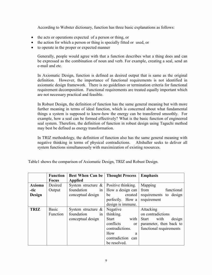
9
According to Webster dictionary, function has three basic explanations as follows:
• the acts or operations expected of a person or thing, or • the action for which a person or thing is specially fitted or used, or • to operate in the proper or expected manner
Generally, people would agree with that a function describes what a thing does and can be expressed as the combination of noun and verb. For example, creating a seal, send an e-mail and etc. In Axiomatic Design, function is defined as desired output that is same as the original definition. However, the importance of functional requirements is not identified in axiomatic design framework. There is no guidelines or termination criteria for functional requirement decomposition. Functional requirements are treated equally important which are not necessary practical and feasible. In Robust Design, the definition of function has the same general meaning but with more further meaning in terms of ideal function, which is concerned about what fundamental things a system is supposed to know-how the energy can be transferred smoothly. For example, how a seal can be formed effectively? What is the basic function of engineered seal system. Therefore, the definition of function in robust design using Taguchi method may best be defined as energy transformation. In TRIZ methodology, the definition of function also has the same general meaning with negative thinking in terms of physical contradictions. Altshuller seeks to deliver all system functions simultaneously with maximization of existing resources.
Table1 shows the comparison of Axiomatic Design, TRIZ and Robust Design.
Function
Focus Best When Can be Applied
Thought Process Emphasis
Axioma-tic Design
Desired Output
System structure & foundation in conceptual design
Positive thinking. How a design can be created perfectly. How a design is immune.
Mapping from functional requirements to design requirement
TRIZ Basic Function
System structure & foundation in conceptual design
Negative thinking. Start with conflicts or contradictions. How a contradiction can be resolved.
Attacking on contradictions Start with design parameter, then back to functional requirements

10
Robust Design
Energy Transfor-mation
Given specific technology optimization or a given structure or concept design optimization
Within a given structure or design, how an engineered system can be optimized to desensitize the side effects of uncontrollable conditions.
Effective application of engineering strategies Identify Ideal Function (ideal relationship) Start with a proper system output response, then maximize the system’s useful function
Table 1: Comparison of Axiomatic Design, TRIZ, Robust Design Table 2 shows the comparison using design axioms.
Independence Axiom Information Axiom Axiomatic Design • Maintain the independence of the
functional requirements Minimize the information
TRIZ • Elimination of technical or physical contractions (maintaining independence of parameters
Concept of ideality
Robust Design • Identify ideal function • Select proper system output
characteristic and control factors to promote the additivity of effects of parameters
Maximize Signal-to-Noise (S/N) Ratio
Table 2: Comparison using Design Axioms
Based on the comparisons above, we can see that these three disciplines have their own focuses. They are complementary each other. The strengths and weakness are summarized in Table 3. Strengths Weakness Axiomatic Design • Provide a good
structural foundation for system (concept design)
• Design Axioms a strong referent
• Domains well defined • Quantitative models for
coupled, uncoupled and decoupled design
• Customer attributes are vague
• “Zigzagging” between domains is lengthy
• Information content is difficult to be applied
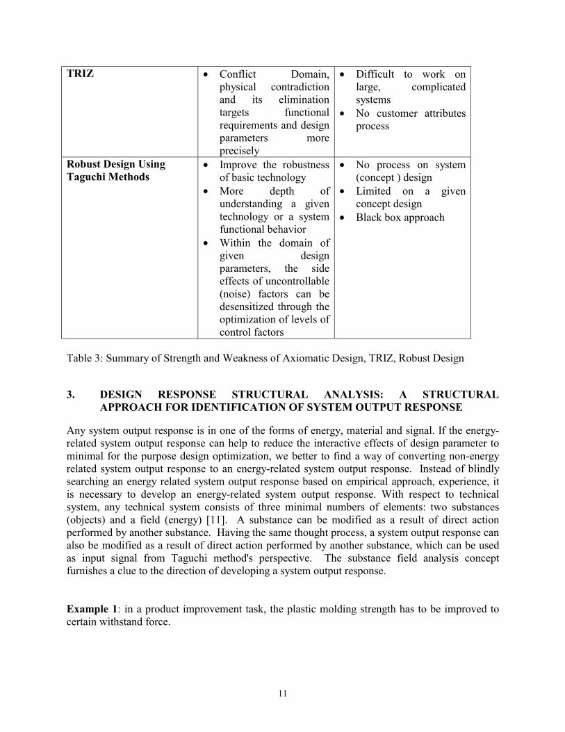
11
TRIZ • Conflict Domain, physical contradiction and its elimination targets functional requirements and design parameters more precisely
• Difficult to work on large, complicated systems
• No customer attributes process
Robust Design Using Taguchi Methods
• Improve the robustness of basic technology
• More depth of understanding a given technology or a system functional behavior
• Within the domain of given design parameters, the side effects of uncontrollable (noise) factors can be desensitized through the optimization of levels of control factors
• No process on system (concept ) design
• Limited on a given concept design
• Black box approach
Table 3: Summary of Strength and Weakness of Axiomatic Design, TRIZ, Robust Design 3. DESIGN RESPONSE STRUCTURAL ANALYSIS: A STRUCTURAL
APPROACH FOR IDENTIFICATION OF SYSTEM OUTPUT RESPONSE Any system output response is in one of the forms of energy, material and signal. If the energy-related system output response can help to reduce the interactive effects of design parameter to minimal for the purpose design optimization, we better to find a way of converting non-energy related system output response to an energy-related system output response. Instead of blindly searching an energy related system output response based on empirical approach, experience, it is necessary to develop an energy-related system output response. With respect to technical system, any technical system consists of three minimal numbers of elements: two substances (objects) and a field (energy) [11]. A substance can be modified as a result of direct action performed by another substance. Having the same thought process, a system output response can also be modified as a result of direct action performed by another substance, which can be used as input signal from Taguchi method's perspective. The substance field analysis concept furnishes a clue to the direction of developing a system output response. Example 1: in a product improvement task, the plastic molding strength has to be improved to certain withstand force.
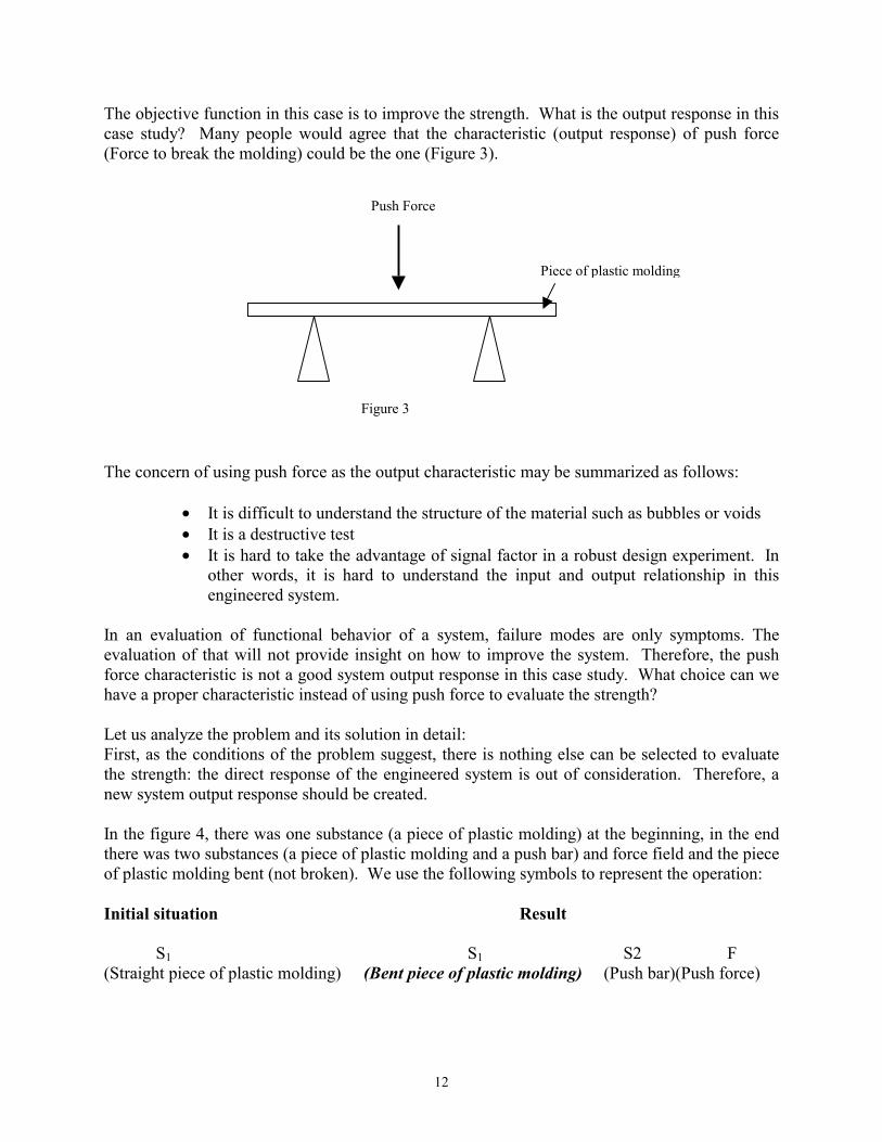
12
The objective function in this case is to improve the strength. What is the output response in this case study? Many people would agree that the characteristic (output response) of push force (Force to break the molding) could be the one (Figure 3). The concern of using push force as the output characteristic may be summarized as follows:
• It is difficult to understand the structure of the material such as bubbles or voids • It is a destructive test • It is hard to take the advantage of signal factor in a robust design experiment. In
other words, it is hard to understand the input and output relationship in this engineered system.
In an evaluation of functional behavior of a system, failure modes are only symptoms. The evaluation of that will not provide insight on how to improve the system. Therefore, the push force characteristic is not a good system output response in this case study. What choice can we have a proper characteristic instead of using push force to evaluate the strength? Let us analyze the problem and its solution in detail: First, as the conditions of the problem suggest, there is nothing else can be selected to evaluate the strength: the direct response of the engineered system is out of consideration. Therefore, a new system output response should be created. In the figure 4, there was one substance (a piece of plastic molding) at the beginning, in the end there was two substances (a piece of plastic molding and a push bar) and force field and the piece of plastic molding bent (not broken). We use the following symbols to represent the operation: Initial situation Result
S1 S1 S2 F (Straight piece of plastic molding) (Bent piece of plastic molding) (Push bar)(Push force)
Push Force
Piece of plastic molding
Figure 3
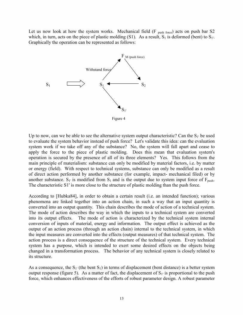
13
Let us now look at how the system works. Mechanical field (F push force) acts on push bar S2 which, in turn, acts on the piece of plastic molding (S1). As a result, S1 is deformed (bent) to S1'. Graphically the operation can be represented as follows: Up to now, can we be able to see the alternative system output characteristic? Can the S1' be used to evaluate the system behavior instead of push force? Let's validate this idea: can the evaluation system work if we take off any of the substance? No, the system will fall apart and cease to apply the force to the piece of plastic molding. Does this mean that evaluation system's operation is secured by the presence of all of its three elements? Yes. This follows from the main principle of materialism: substance can only be modified by material factors, i.e. by matter or energy (field). With respect to technical systems, substance can only be modified as a result of direct action performed by another substance (for example, impact- mechanical filed) or by another substance. S1' is modified from S1 and is the output due to system input force of Fpush. The characteristic S1' is more close to the structure of plastic molding than the push force. According to [Hubka84], in order to obtain a certain result (i.e. an intended function); various phenomena are linked together into an action chain, in such a way that an input quantity is converted into an output quantity. This chain describes the mode of action of a technical system. The mode of action describes the way in which the inputs to a technical system are converted into its output effects. The mode of action is characterized by the technical system internal conversion of inputs of material, energy and information. The output effect is achieved as the output of an action process (through an action chain) internal to the technical system, in which the input measures are converted into the effects (output measures) of that technical system. The action process is a direct consequence of the structure of the technical system. Every technical system has a purpose, which is intended to exert some desired effects on the objects being changed in a transformation process. The behavior of any technical system is closely related to its structure. As a consequence, the S1' (the bent S1) in terms of displacement (bent distance) is a better system output response (figure 5). As a matter of fact, the displacement of S1' is proportional to the push force, which enhances effectiveness of the efforts of robust parameter design. A robust parameter
Withstand force
S1 S2
F M (push force)
S1'
S1
Figure 4
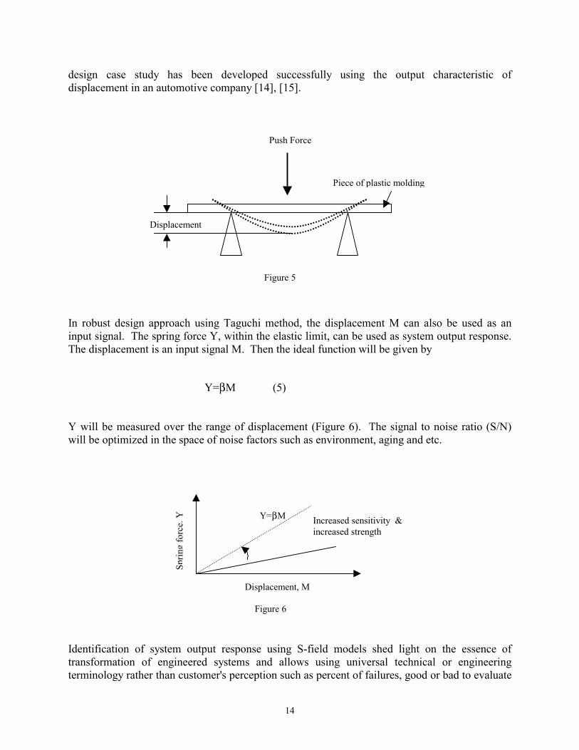
14
design case study has been developed successfully using the output characteristic of displacement in an automotive company [14], [15]. In robust design approach using Taguchi method, the displacement M can also be used as an input signal. The spring force Y, within the elastic limit, can be used as system output response. The displacement is an input signal M. Then the ideal function will be given by
Y=βM (5) Y will be measured over the range of displacement (Figure 6). The signal to noise ratio (S/N) will be optimized in the space of noise factors such as environment, aging and etc. Identification of system output response using S-field models shed light on the essence of transformation of engineered systems and allows using universal technical or engineering terminology rather than customer's perception such as percent of failures, good or bad to evaluate
Y=βM
Displacement, M
Sprin
g fo
rce,
Y
Increased sensitivity & increased strength
Figure 6
Displacement
Push Force
Piece of plastic molding
Figure 5
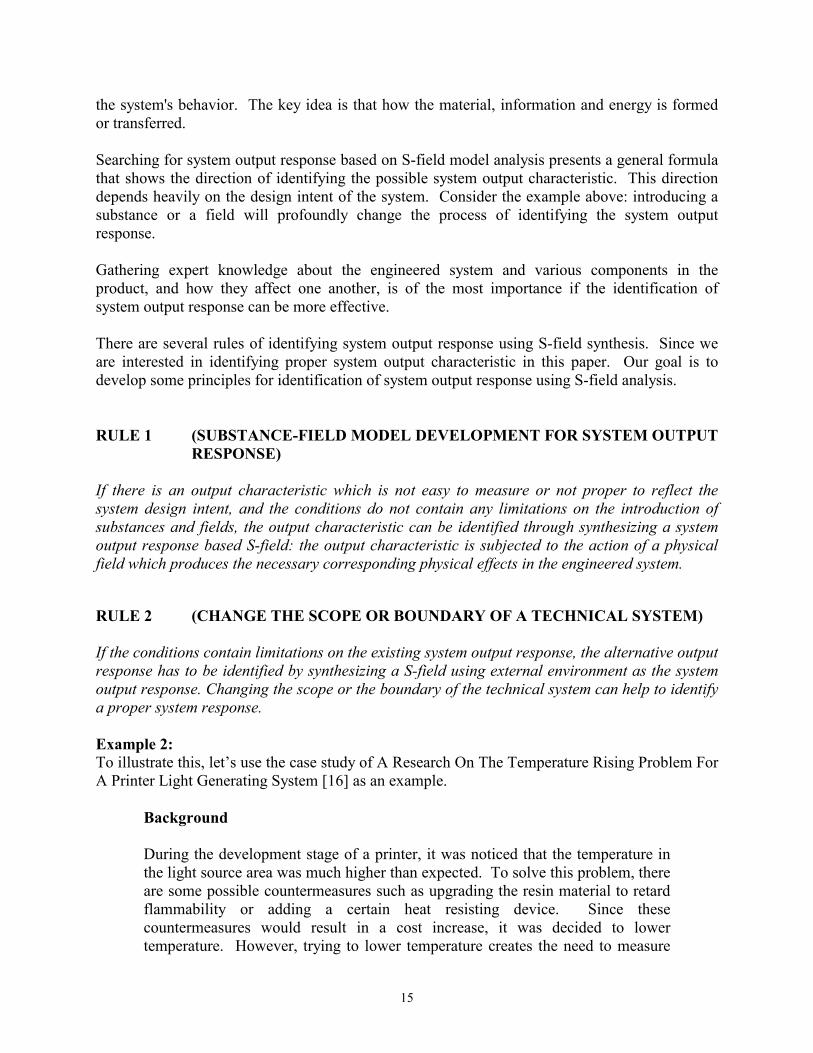
15
the system's behavior. The key idea is that how the material, information and energy is formed or transferred. Searching for system output response based on S-field model analysis presents a general formula that shows the direction of identifying the possible system output characteristic. This direction depends heavily on the design intent of the system. Consider the example above: introducing a substance or a field will profoundly change the process of identifying the system output response. Gathering expert knowledge about the engineered system and various components in the product, and how they affect one another, is of the most importance if the identification of system output response can be more effective. There are several rules of identifying system output response using S-field synthesis. Since we are interested in identifying proper system output characteristic in this paper. Our goal is to develop some principles for identification of system output response using S-field analysis. RULE 1 (SUBSTANCE-FIELD MODEL DEVELOPMENT FOR SYSTEM OUTPUT
RESPONSE) If there is an output characteristic which is not easy to measure or not proper to reflect the system design intent, and the conditions do not contain any limitations on the introduction of substances and fields, the output characteristic can be identified through synthesizing a system output response based S-field: the output characteristic is subjected to the action of a physical field which produces the necessary corresponding physical effects in the engineered system. RULE 2 (CHANGE THE SCOPE OR BOUNDARY OF A TECHNICAL SYSTEM) If the conditions contain limitations on the existing system output response, the alternative output response has to be identified by synthesizing a S-field using external environment as the system output response. Changing the scope or the boundary of the technical system can help to identify a proper system response. Example 2: To illustrate this, let’s use the case study of A Research On The Temperature Rising Problem For A Printer Light Generating System [16] as an example.
Background
During the development stage of a printer, it was noticed that the temperature in the light source area was much higher than expected. To solve this problem, there are some possible countermeasures such as upgrading the resin material to retard flammability or adding a certain heat resisting device. Since these countermeasures would result in a cost increase, it was decided to lower temperature. However, trying to lower temperature creates the need to measure
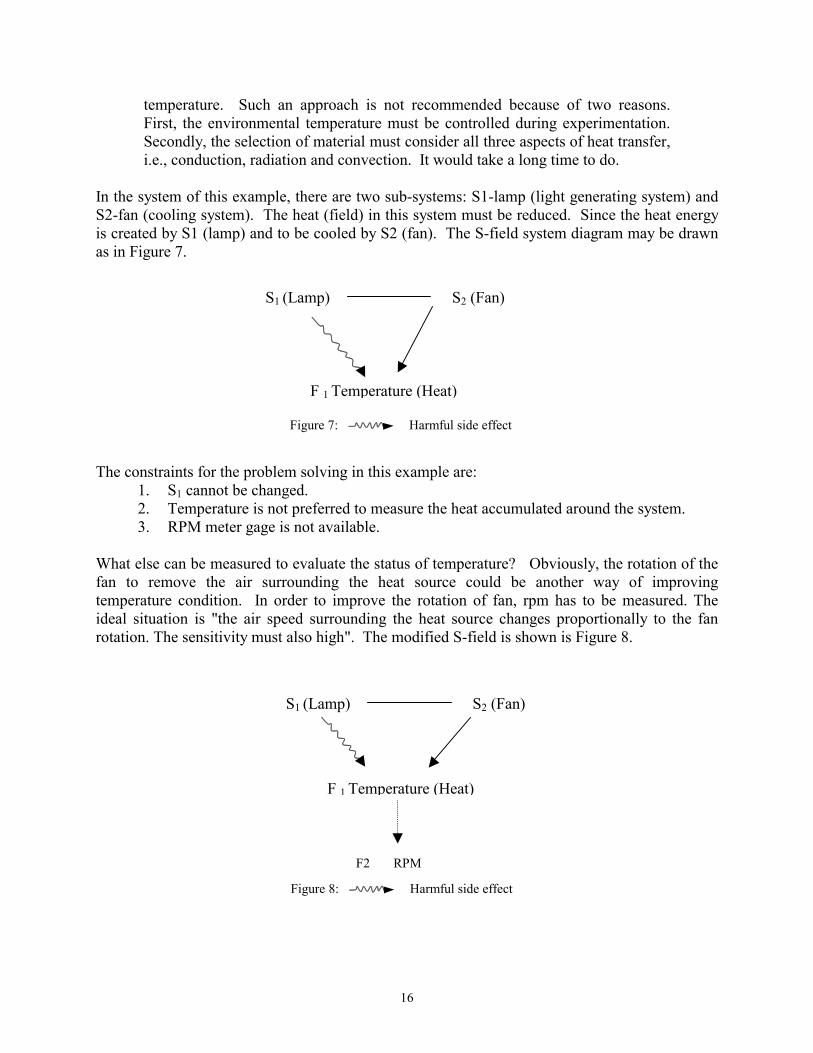
16
temperature. Such an approach is not recommended because of two reasons. First, the environmental temperature must be controlled during experimentation. Secondly, the selection of material must consider all three aspects of heat transfer, i.e., conduction, radiation and convection. It would take a long time to do.
In the system of this example, there are two sub-systems: S1-lamp (light generating system) and S2-fan (cooling system). The heat (field) in this system must be reduced. Since the heat energy is created by S1 (lamp) and to be cooled by S2 (fan). The S-field system diagram may be drawn as in Figure 7. The constraints for the problem solving in this example are:
1. S1 cannot be changed. 2. Temperature is not preferred to measure the heat accumulated around the system. 3. RPM meter gage is not available.
What else can be measured to evaluate the status of temperature? Obviously, the rotation of the fan to remove the air surrounding the heat source could be another way of improving temperature condition. In order to improve the rotation of fan, rpm has to be measured. The ideal situation is "the air speed surrounding the heat source changes proportionally to the fan rotation. The sensitivity must also high". The modified S-field is shown is Figure 8.
S1 (Lamp) S2 (Fan)
F 1 Temperature (Heat)
Figure 7: Harmful side effect
S1 (Lamp) S2 (Fan)
F 1 Temperature (Heat)
Figure 8: Harmful side effect
F2 RPM
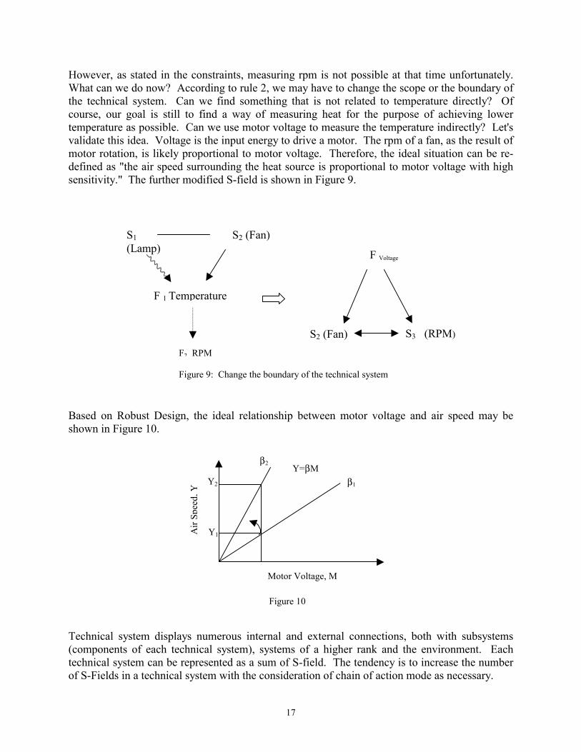
17
However, as stated in the constraints, measuring rpm is not possible at that time unfortunately. What can we do now? According to rule 2, we may have to change the scope or the boundary of the technical system. Can we find something that is not related to temperature directly? Of course, our goal is still to find a way of measuring heat for the purpose of achieving lower temperature as possible. Can we use motor voltage to measure the temperature indirectly? Let's validate this idea. Voltage is the input energy to drive a motor. The rpm of a fan, as the result of motor rotation, is likely proportional to motor voltage. Therefore, the ideal situation can be re-defined as "the air speed surrounding the heat source is proportional to motor voltage with high sensitivity." The further modified S-field is shown in Figure 9. Based on Robust Design, the ideal relationship between motor voltage and air speed may be shown in Figure 10. Technical system displays numerous internal and external connections, both with subsystems (components of each technical system), systems of a higher rank and the environment. Each technical system can be represented as a sum of S-field. The tendency is to increase the number of S-Fields in a technical system with the consideration of chain of action mode as necessary.
Figure 9: Change the boundary of the technical system
S2 (Fan) S1 (Lamp)
F 1 Temperature
F2 RPM
F Voltage
S2 (Fan) S3 (RPM)
β2
Y1
Y2 Y=βM
Motor Voltage, M
Air
Spee
d, Y
Figure 10
β1
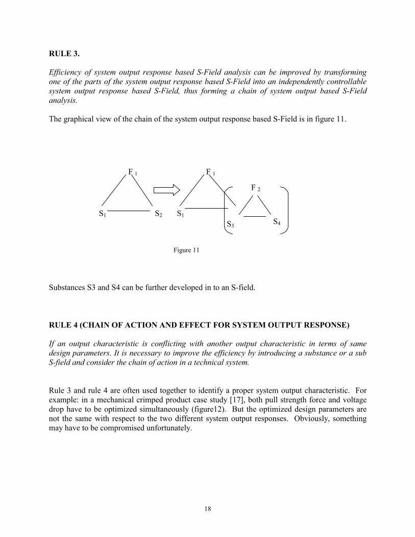
18
RULE 3. Efficiency of system output response based S-Field analysis can be improved by transforming one of the parts of the system output response based S-Field into an independently controllable system output response based S-Field, thus forming a chain of system output based S-Field analysis. The graphical view of the chain of the system output response based S-Field is in figure 11. Substances S3 and S4 can be further developed in to an S-field. RULE 4 (CHAIN OF ACTION AND EFFECT FOR SYSTEM OUTPUT RESPONSE) If an output characteristic is conflicting with another output characteristic in terms of same design parameters. It is necessary to improve the efficiency by introducing a substance or a sub S-field and consider the chain of action in a technical system. Rule 3 and rule 4 are often used together to identify a proper system output characteristic. For example: in a mechanical crimped product case study [17], both pull strength force and voltage drop have to be optimized simultaneously (figure12). But the optimized design parameters are not the same with respect to the two different system output responses. Obviously, something may have to be compromised unfortunately.
S1 S2
F 1
S1
F 1
S3 S4
F 2
Figure 11
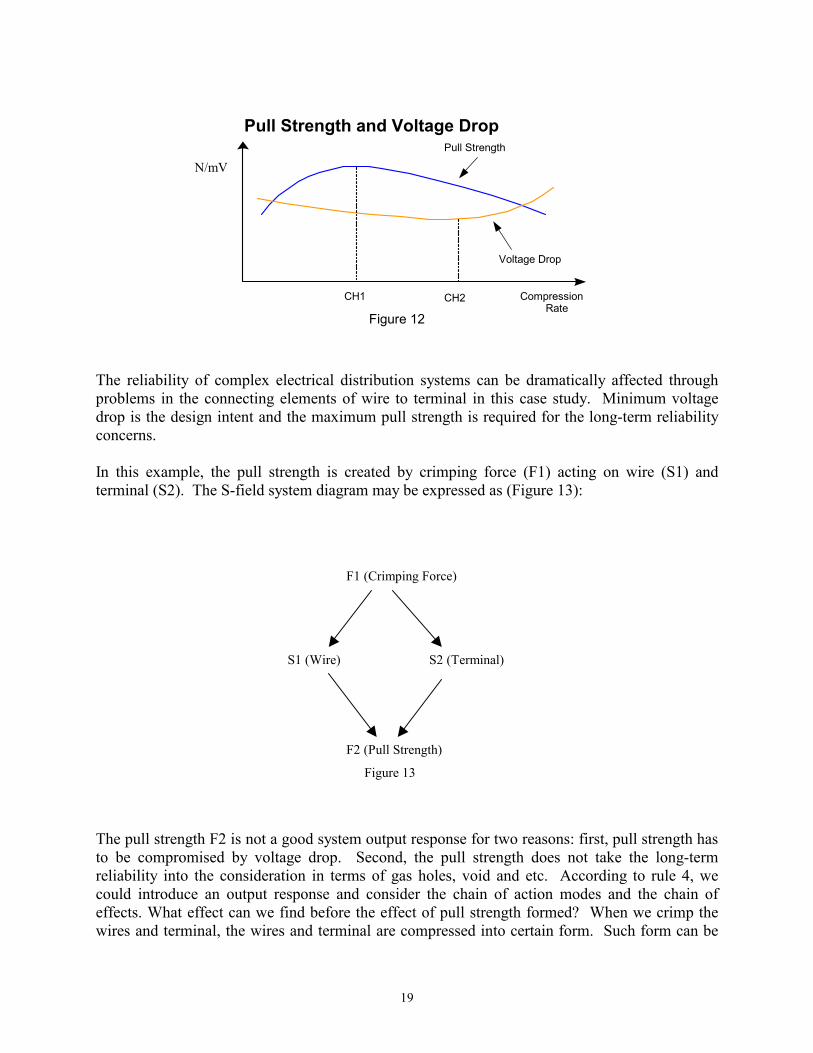
19
The reliability of complex electrical distribution systems can be dramatically affected through problems in the connecting elements of wire to terminal in this case study. Minimum voltage drop is the design intent and the maximum pull strength is required for the long-term reliability concerns. In this example, the pull strength is created by crimping force (F1) acting on wire (S1) and terminal (S2). The S-field system diagram may be expressed as (Figure 13): The pull strength F2 is not a good system output response for two reasons: first, pull strength has to be compromised by voltage drop. Second, the pull strength does not take the long-term reliability into the consideration in terms of gas holes, void and etc. According to rule 4, we could introduce an output response and consider the chain of action modes and the chain of effects. What effect can we find before the effect of pull strength formed? When we crimp the wires and terminal, the wires and terminal are compressed into certain form. Such form can be
Pull Strength and Voltage Drop
Compression Rate
CH1 CH2
Pull Strength
Voltage Drop
Figure 12
N/mV
S1 (Wire) S2 (Terminal)
F1 (Crimping Force)
F2 (Pull Strength)
Figure 13
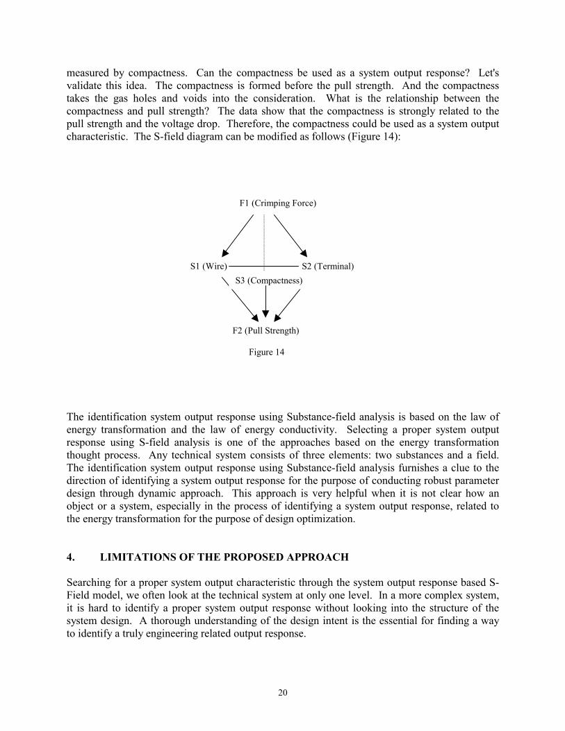
20
measured by compactness. Can the compactness be used as a system output response? Let's validate this idea. The compactness is formed before the pull strength. And the compactness takes the gas holes and voids into the consideration. What is the relationship between the compactness and pull strength? The data show that the compactness is strongly related to the pull strength and the voltage drop. Therefore, the compactness could be used as a system output characteristic. The S-field diagram can be modified as follows (Figure 14): The identification system output response using Substance-field analysis is based on the law of energy transformation and the law of energy conductivity. Selecting a proper system output response using S-field analysis is one of the approaches based on the energy transformation thought process. Any technical system consists of three elements: two substances and a field. The identification system output response using Substance-field analysis furnishes a clue to the direction of identifying a system output response for the purpose of conducting robust parameter design through dynamic approach. This approach is very helpful when it is not clear how an object or a system, especially in the process of identifying a system output response, related to the energy transformation for the purpose of design optimization. 4. LIMITATIONS OF THE PROPOSED APPROACH Searching for a proper system output characteristic through the system output response based S-Field model, we often look at the technical system at only one level. In a more complex system, it is hard to identify a proper system output response without looking into the structure of the system design. A thorough understanding of the design intent is the essential for finding a way to identify a truly engineering related output response.
S1 (Wire) S2 (Terminal)
F1 (Crimping Force)
F2 (Pull Strength) Figure 14
S3 (Compactness)
21
5. FURTHER RESEARCH One interesting topic might be to investigate how the framework of Axiomatic Design could be used to improve the limitations of identifying system output response using substance-field analysis. Of course, we would like to investigate a way of bridging the gap between the conceptual design and parameter design so that the upfront robustness thinking and the testability can be emphasized. Design through axiomatic approach is attained by interactions between the goal of the designer and the method used to achieve the goal. The goal of the design is always proposed in the functional domain, and the method of achieving the goal is proposed in the physical domain. Design process is the mapping or assigning relationship between the domains for all the levels of design. As the functional requirements become diverse, satisfying the requirements become more difficult. Therefore, concentrating on the functional requirements for the given stage or level of the design process is necessary. A design or a problem with many variables is very complicated. In order to prioritize the tasks and the proper focus, it is necessary to sort the primary and secondary functional requirements and handle each functional requirement according to the precedence of importance. For the purpose of design evaluation and optimization, it is essential to select a proper system output response to evaluate and understand an engineered system or a product 's functional behavior. Such system output characteristic (response) should be basic function related. Basic function is a function to transfer material, energy and information from the input of the system to the output of the system. Obviously, the basic function of a product or process technology is related to its capability (highest probability) to transform input to output in terms of material, information and energy. Functional requirement is included in the functional domain. The designer should thoroughly understand problem in the functional domain and should not limit any possible selections without a special reason. Clearly defining the problem is closely related to defining the functional requirements. On the other hand the designer should select the design elements in the physical domain by specifying the functional requirements physically. Selecting a system output response characteristic is closely related to the physical domain to reflect how material, information and energy are transferred smoothly from input to output in the technical system. According the axiomatic design principles, the essence of design process lies in the hierarchies. The designer begins with functional requirements (top-down approach). And because of the different priorities of all the functional requirements, the designer can categorize all the functional requirements into different hierarchies. The important point in this process is that the functional requirements must be satisfied with specific design parameters. As it goes to the lower level more details should be considered. This can be a very effective way of considering all details of the design. The functional requirements of the higher level must be satisfied through the appropriate design parameters in order for the lower level functional requirements to be satisfied. By using axiomatic approach the ideas in the initial stages of the design can be materialized in a scientific way. Once the design zigzagging mappings have been completed according to the
22
design axiom. One of the most of important tasks is to understand how the system behavior can be evaluated. In order to evaluate the system's functional behavior, of course, a key system output response has to be identified. The lower level of functional requirement in the axiomatic design framework is not necessary the good system output response for the purpose of system evaluation. But the lower level of functional requirement is certainly the proper starting point to identify or develop a proper system output characteristic. Additional creativity in the design can be induced when going through this task. The bottom-up approach is necessary to identify a system output response based on a result of zigzagging mapping. The details of identifying system output response through axiomatic design axioms are presented in Part II. 6. CONCLUSIONS This paper suggests an approach for identifying a proper system output response using substance-field analysis along with the analysis of chain of action mode. The approach presented consists of four rules:
(1) System output response focused substance-field model development (2) Change the scope or boundary of a technical system (3) Efficiency of system output response focused substance-field model (4) Chain of action and effect for system output response
The law of energy transformation and the law of energy conductivity guide the identification of system output response using substance-field analysis. One of the biggest advantages using this approach is that the signal factor will come with the identified system output response. With the proper identification of signal factor and the system output response, the chance of using dynamic robust design will be increased. Of course, the effectiveness of the robust parameter design will be improved. Compared with other approaches to the identification of system output response, the approach presented in this paper provides a specific and detail directions to not only search for but create an energy related system output response. The presented approach was successfully applied to several challenging case studies at some automotive companies. The findings from the case studies motivated the research to bridge the gap between the robust conceptual design and the robust parameter design. REFERENCES [1] Taguchi, G., Taguchi ON ROBUST TECHNOLOGY DEVELOPMENT Bring Quality
Engineering Upstream, 1993, The American Society of Mechanical Engineers, Yew York, NY.
[2] Taguchi, G., System of Experimental Design, Unipub/Kraus International Publications, White Plain, NY, 1987.
23
[3] Phadke, M.S., Quality Engineering Using Robust Design, Prentice-Hall, Englewood Cliffs, NJ, 1989.
[4] Nair, Vijayan N., "Taguchi's Parameter Design: A Panel Discussion," ECHNOMETERICS, May 1992, Vol. 34, No. 2.
[5] ReVelle, J. B., Moran J.W., and Cox, C.A., The QFD Handbook, John Wiley & Sons, INC. 1998.
[6] Box, G.E, and Draper, N. R., Empirical Model-Building and Response Surface Methodology, John Wiley and Sons, NY, 1988.
[7] Wasserman, G.S., "The Use of Energy-Related Characteristics in Robust Product Design.", Quality Engineering, 10(2), 213-222 (1997-1998).
[8] Pahl, G., and Beitz, W., 1988, Engineering Design: A Systematic Approach, Springer Verlag.
[9] Hubka, V., and Eder, W. E., 1984, Theory of Technical System: A Total Concept Theory for Engineering Design, Springer-Verlag.
[10] Clausing, D., "Product Development, Robust Design, and Education.", 1998, 4th Annual Total Product Development Symposium, American Supplier Institute.
[11] Salamatov, Y. "TRIZ: The Right Solution at the Right Time." Published by Insytec B.V. 1999.
[12] Terninko, J., Zusman, A., and Zlotin, B., "Step-by-Step: Creating Innovative Solution Concepts." 1996, Responsible Management Inc.
[13] Suh, N.P., 1990, The Principles of Design, New York, NY: Oxford University Press. [14] "Improvement of An Aero-Craft Material Casting Process.", Quality Engineering Forum,
1995. Japan. [15] Hu, M., "Reduction of Product Development Cycle Time." 3rd Annual International Total
Product Development Symposium, 1997, American Supplier Institute. [16] "A Research on the Temperature Rising Problem for a Printer Light Generating System."
Quality Engineering Forum, 1996, Japan. [17] Hu, M., Meder, A., Boston, M., "Mechanical Crimping Process Improvement Using
Robust Design Techniques." Robust Engineering: 17th Annual Taguchi Methods Symposium Processdings, 1999, Cambridge, Massachusetts. American Supplier Institute.
[18] Altshuller, G., translated by Shulyak, L., And Suddenly the Inventor Appeared-TRIZ, the Theory of Inventive Problem Solving, Technical Innovation Center, INC. Worcester, MA, 1996.

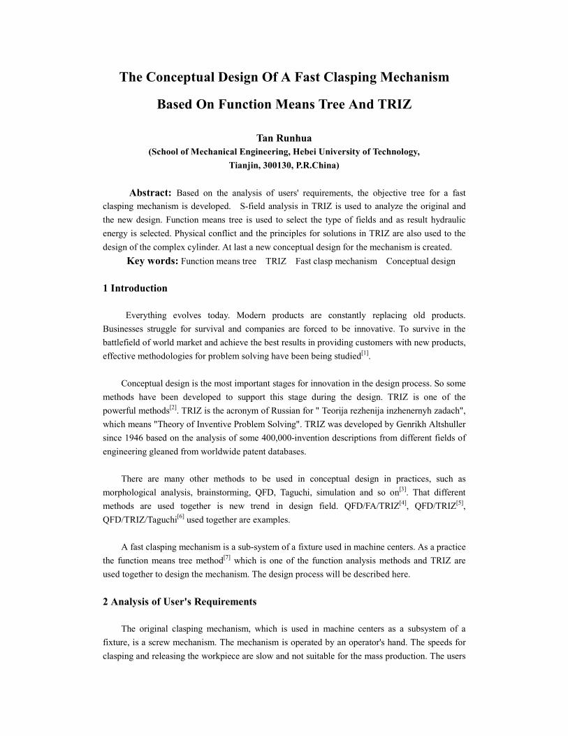
The Conceptual Design Of A Fast Clasping Mechanism
Based On Function Means Tree And TRIZ
Tan Runhua (School of Mechanical Engineering, Hebei University of Technology,
Tianjin, 300130, P.R.China)
Abstract: Based on the analysis of users' requirements, the objective tree for a fast clasping mechanism is developed. S-field analysis in TRIZ is used to analyze the original and the new design. Function means tree is used to select the type of fields and as result hydraulic energy is selected. Physical conflict and the principles for solutions in TRIZ are also used to the design of the complex cylinder. At last a new conceptual design for the mechanism is created. Key words: Function means tree TRIZ Fast clasp mechanism Conceptual design 1 Introduction Everything evolves today. Modern products are constantly replacing old products. Businesses struggle for survival and companies are forced to be innovative. To survive in the battlefield of world market and achieve the best results in providing customers with new products, effective methodologies for problem solving have been being studied[1]. Conceptual design is the most important stages for innovation in the design process. So some methods have been developed to support this stage during the design. TRIZ is one of the powerful methods[2]. TRIZ is the acronym of Russian for " Teorija rezhenija inzhenernyh zadach", which means "Theory of Inventive Problem Solving". TRIZ was developed by Genrikh Altshuller since 1946 based on the analysis of some 400,000-invention descriptions from different fields of engineering gleaned from worldwide patent databases.
There are many other methods to be used in conceptual design in practices, such as morphological analysis, brainstorming, QFD, Taguchi, simulation and so on[3]. That different methods are used together is new trend in design field. QFD/FA/TRIZ[4], QFD/TRIZ[5], QFD/TRIZ/Taguchi[6] used together are examples.
A fast clasping mechanism is a sub-system of a fixture used in machine centers. As a practice the function means tree method[7] which is one of the function analysis methods and TRIZ are used together to design the mechanism. The design process will be described here. 2 Analysis of User's Requirements
The original clasping mechanism, which is used in machine centers as a subsystem of a fixture, is a screw mechanism. The mechanism is operated by an operator's hand. The speeds for clasping and releasing the workpiece are slow and not suitable for the mass production. The users

hope that a new product should be designed for the fast clasping and releasing operations. The first step of the design is the analysis of users' requirements. The original users'
requirements are usually not clear enough to be used by designers. The analysis of the users' requirements is to translate the original users' requirements to clear design objects. There are several methods for this purpose. Object tree method is one of them[8]. After discussing with users the object tree for the new design is developed and shown in Fig.1. For a group of workpieces with same dimensions to be machined the mechanism should be adjusted in a short distance but for the workpieces with different dimensions it should be adjusted in a long distance. The designers can carry on design depending on the objects in the tree. overload protected safety few operating errors enough clasping force easy to change workpiece simple easy for measurement operation simple fast easy for maintenance clasping mechanism fast clasp fast clasp and release fast release to suite wide dimensions for workpieces low cost Fig. 1 Object tree for the new design 3 S-Field Analysis
Function analysis is the basic step to apply TRIZ. In TRIZ all functions can be decomposed into three basic elements: "two substances and a field". The diagram model for a function is shown in Fig.2.
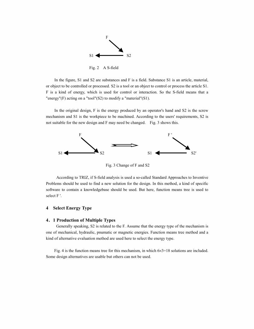
F S1 S2 Fig. 2 A S-field
In the figure, S1 and S2 are substances and F is a field. Substance S1 is an article, material, or object to be controlled or processed. S2 is a tool or an object to control or process the article S1. F is a kind of energy, which is used for control or interaction. So the S-field means that a "energy"(F) acting on a "tool"(S2) to modify a "material"(S1).
In the original design, F is the energy produced by an operator's hand and S2 is the screw mechanism and S1 is the workpiece to be machined. According to the users' requirements, S2 is not suitable for the new design and F may need be changed. Fig. 3 shows this. F F ' S1 S2 S1 S2' Fig. 3 Change of F and S2 According to TRIZ, if S-field analysis is used a so-called Standard Approaches to Inventive Problems should be used to find a new solution for the design. In this method, a kind of specific software to contain a knowledgebase should be used. But here, function means tree is used to select F '. 4 Select Energy Type 4....1 Production of Multiple Types Generally speaking, S2 is related to the F. Assume that the energy type of the mechanism is one of mechanical, hydraulic, pnumatic or magnetic energies. Function means tree method and a kind of alternative evaluation method are used here to select the energy type.
Fig. 4 is the function means tree for this mechanism, in which 6×3=18 solutions are included. Some design alternatives are usable but others can not be used.
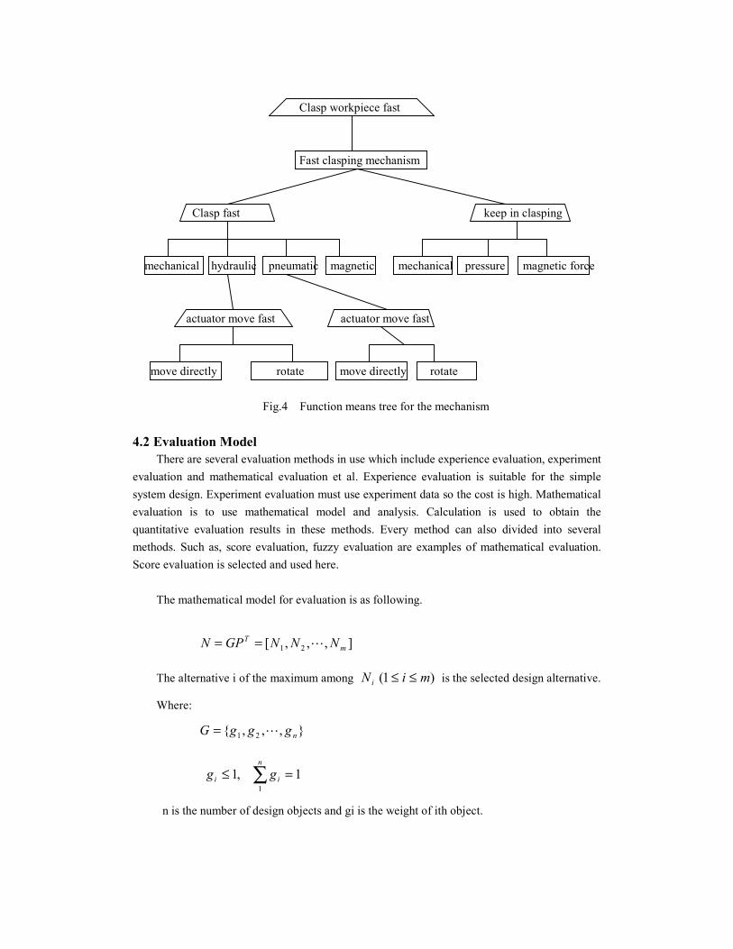
Clasp workpiece fast Fast clasping mechanism Clasp fast keep in clasping mechanical hydraulic pneumatic magnetic mechanical pressure magnetic force actuator move fast actuator move fast move directly rotate move directly rotate Fig.4 Function means tree for the mechanism 4.2 Evaluation Model
There are several evaluation methods in use which include experience evaluation, experiment evaluation and mathematical evaluation et al. Experience evaluation is suitable for the simple system design. Experiment evaluation must use experiment data so the cost is high. Mathematical evaluation is to use mathematical model and analysis. Calculation is used to obtain the quantitative evaluation results in these methods. Every method can also divided into several methods. Such as, score evaluation, fuzzy evaluation are examples of mathematical evaluation. Score evaluation is selected and used here.
The mathematical model for evaluation is as following.
],,,[ 21 mT NNNGPN L==
The alternative i of the maximum among )1( miNi ≤≤ is the selected design alternative.
Where:
},,,{ 21 ngggG L=
1,11
=≤ ∑n
ii gg
n is the number of design objects and gi is the weight of ith object.

=
mnmm
n
n
PPP
PPPPPP
P
L
MMMM
L
L
21
22221
11211
m is the number of design alternatives. ijP is the score of the ith alternative and jth object.
The following 5 design objectives chosen from the object tree are listed in relative important order.
(1) Clasp the workpiece fast. (2) Produce enough force to clasp the workpiece.
(3)to suite wide dimensions of workpieces. (4)Volume is small. (5)The cost is low. Determine the vector G as following.
}1.0,15.0,25.0,25.0,25.0{====G
Assume that there are 4 energy types as design alternatives, which are mechanical, hydraulic, pneumatic and magnetic. 9 grade score is selected and P matrix is obtained.
====
43778738487888886866
P
]6.42.69.77.6[
47783386788874868886
]1.015.025.025.025.0[ ====
====N
Because the second score is the largest the hydraulic energy is selected as the energy type. 5 Design of the Tool There are two kinds of actuators driven by hydraulic energy, which are hydraulic motor and cylinder. Hydraulic cylinder is selected for this specific use considering that the volume of the
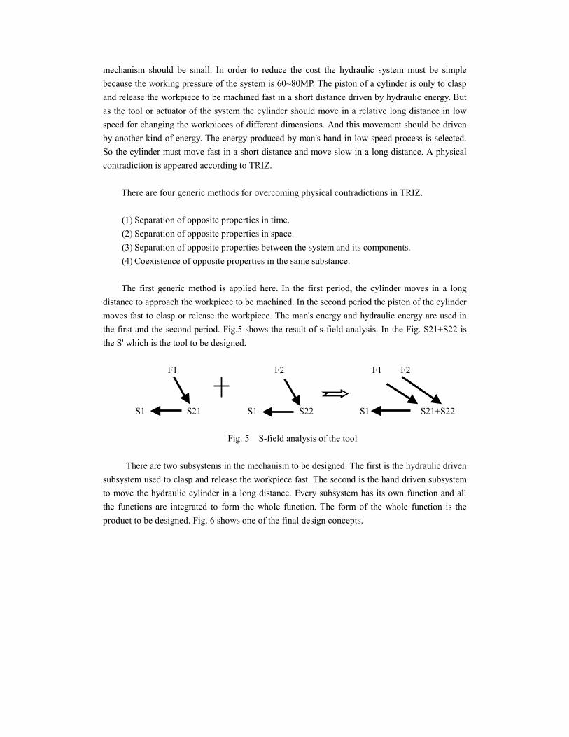
mechanism should be small. In order to reduce the cost the hydraulic system must be simple because the working pressure of the system is 60~80MP. The piston of a cylinder is only to clasp and release the workpiece to be machined fast in a short distance driven by hydraulic energy. But as the tool or actuator of the system the cylinder should move in a relative long distance in low speed for changing the workpieces of different dimensions. And this movement should be driven by another kind of energy. The energy produced by man's hand in low speed process is selected. So the cylinder must move fast in a short distance and move slow in a long distance. A physical contradiction is appeared according to TRIZ.
There are four generic methods for overcoming physical contradictions in TRIZ.
(1) Separation of opposite properties in time. (2) Separation of opposite properties in space. (3) Separation of opposite properties between the system and its components. (4) Coexistence of opposite properties in the same substance.
The first generic method is applied here. In the first period, the cylinder moves in a long
distance to approach the workpiece to be machined. In the second period the piston of the cylinder moves fast to clasp or release the workpiece. The man's energy and hydraulic energy are used in the first and the second period. Fig.5 shows the result of s-field analysis. In the Fig. S21+S22 is the S' which is the tool to be designed. F1 F2 F1 F2 S1 S21 S1 S22 S1 S21+S22 Fig. 5 S-field analysis of the tool There are two subsystems in the mechanism to be designed. The first is the hydraulic driven subsystem used to clasp and release the workpiece fast. The second is the hand driven subsystem to move the hydraulic cylinder in a long distance. Every subsystem has its own function and all the functions are integrated to form the whole function. The form of the whole function is the product to be designed. Fig. 6 shows one of the final design concepts.
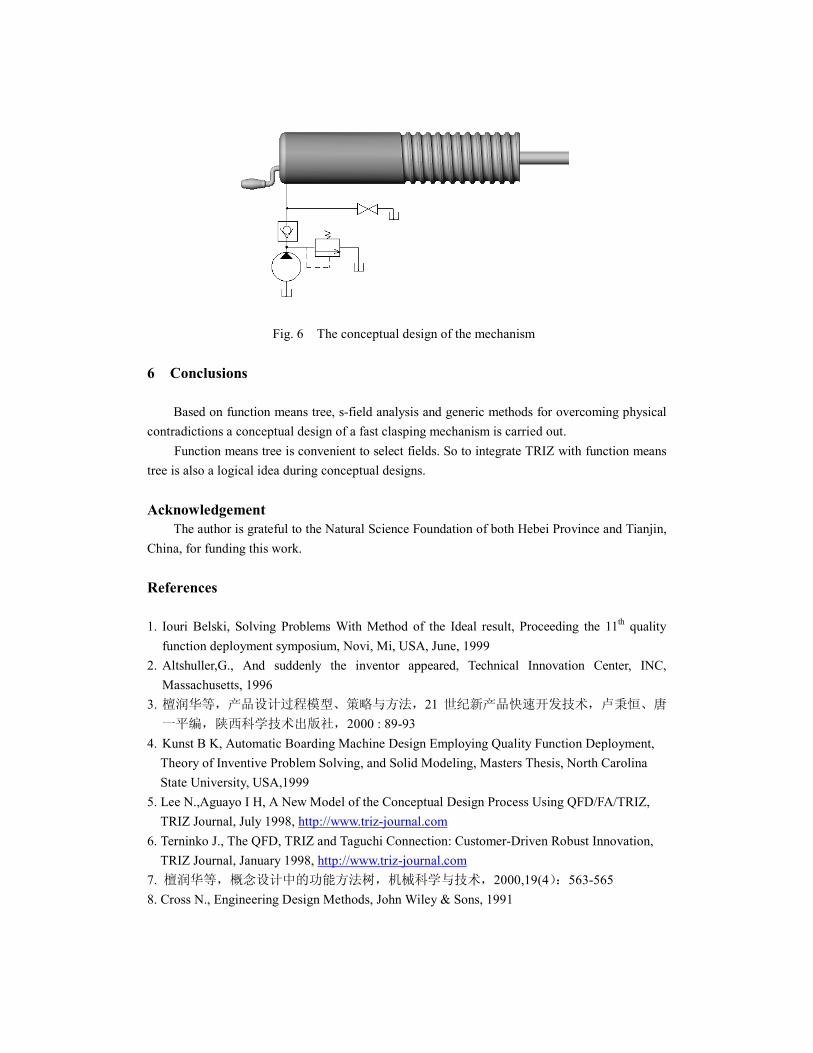
Fig. 6 The conceptual design of the mechanism 6 Conclusions Based on function means tree, s-field analysis and generic methods for overcoming physical contradictions a conceptual design of a fast clasping mechanism is carried out.
Function means tree is convenient to select fields. So to integrate TRIZ with function means tree is also a logical idea during conceptual designs. Acknowledgement
The author is grateful to the Natural Science Foundation of both Hebei Province and Tianjin, China, for funding this work. References 1. Iouri Belski, Solving Problems With Method of the Ideal result, Proceeding the 11th quality
function deployment symposium, Novi, Mi, USA, June, 1999 2. Altshuller,G., And suddenly the inventor appeared, Technical Innovation Center, INC,
Massachusetts, 1996 3. 檀润华等,产品设计过程模型、策略与方法,21 世纪新产品快速开发技术,卢秉恒、唐
一平编,陕西科学技术出版社,2000 : 89-93 4. Kunst B K, Automatic Boarding Machine Design Employing Quality Function Deployment, Theory of Inventive Problem Solving, and Solid Modeling, Masters Thesis, North Carolina State University, USA,1999 5. Lee N.,Aguayo I H, A New Model of the Conceptual Design Process Using QFD/FA/TRIZ, TRIZ Journal, July 1998, http://www.triz-journal.com 6. Terninko J., The QFD, TRIZ and Taguchi Connection: Customer-Driven Robust Innovation, TRIZ Journal, January 1998, http://www.triz-journal.com 7. 檀润华等,概念设计中的功能方法树,机械科学与技术,2000,19(4):563-565 8. Cross N., Engineering Design Methods, John Wiley & Sons, 1991

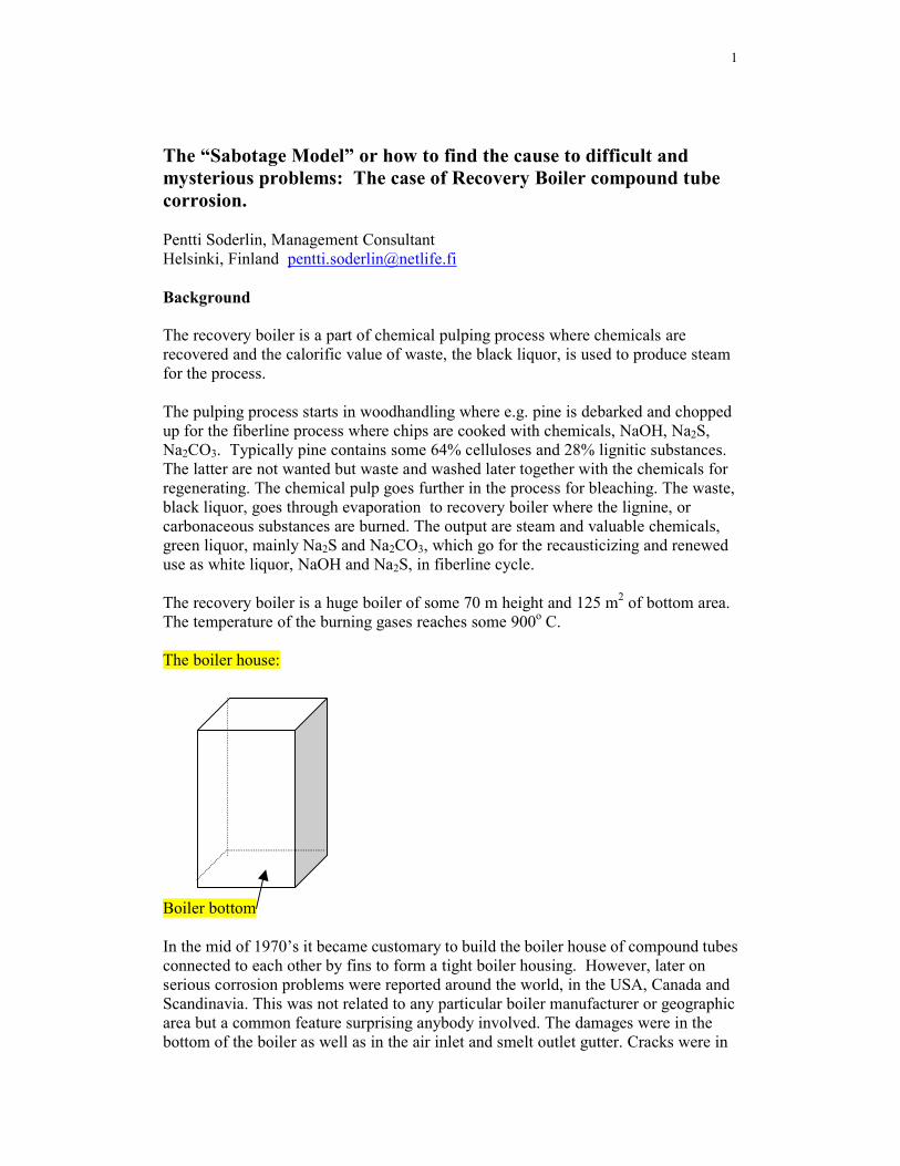
1
The “Sabotage Model” or how to find the cause to difficult and mysterious problems: The case of Recovery Boiler compound tube corrosion. Pentti Soderlin, Management Consultant Helsinki, Finland [email protected] Background The recovery boiler is a part of chemical pulping process where chemicals are recovered and the calorific value of waste, the black liquor, is used to produce steam for the process. The pulping process starts in woodhandling where e.g. pine is debarked and chopped up for the fiberline process where chips are cooked with chemicals, NaOH, Na2S, Na2CO3. Typically pine contains some 64% celluloses and 28% lignitic substances. The latter are not wanted but waste and washed later together with the chemicals for regenerating. The chemical pulp goes further in the process for bleaching. The waste, black liquor, goes through evaporation to recovery boiler where the lignine, or carbonaceous substances are burned. The output are steam and valuable chemicals, green liquor, mainly Na2S and Na2CO3, which go for the recausticizing and renewed use as white liquor, NaOH and Na2S, in fiberline cycle. The recovery boiler is a huge boiler of some 70 m height and 125 m2 of bottom area. The temperature of the burning gases reaches some 900o C. The boiler house: Boiler bottom In the mid of 1970’s it became customary to build the boiler house of compound tubes connected to each other by fins to form a tight boiler housing. However, later on serious corrosion problems were reported around the world, in the USA, Canada and Scandinavia. This was not related to any particular boiler manufacturer or geographic area but a common feature surprising anybody involved. The damages were in the bottom of the boiler as well as in the air inlet and smelt outlet gutter. Cracks were in
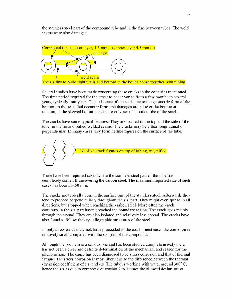
2
the stainless steel part of the compound tube and in the fins between tubes. The weld seams were also damaged. Compound tubes, outer layer, 1,6 mm s.s., inner layer 4,5 mm c.s damages weld seam The s.s.fins to build tight walls and bottom in the boiler house together with tubing Several studies have been made concerning these cracks in the countries mentioned. The time period required for the crack to occur varies from a few months to several years, typically four years. The existence of cracks is due to the geometric form of the bottom. In the so-called decanter form, the damages are all over the bottom at random, in the skewed bottom cracks are only near the outlet tube of the smelt. The cracks have some typical features. They are located in the top and the side of the tube, in the fin and butted welded seams. The cracks may be either longitudinal or perpendicular. In many cases they form netlike figures on the surface of the tube. Net-like crack figures on top of tubing, magnified There have been reported cases where the stainless steel part of the tube has completely come off uncovering the carbon steel. The maximum reported size of such cases has been 50x50 mm. The cracks are typically born in the surface part of the stainless steel. Afterwards they tend to proceed perpendicularly throughout the s.s. part. They might even spread in all directions, but stopped when reaching the carbon steel. More often the crack continues in the s.s. part having reached the boundary region. The crack goes mainly through the crystal. They are also isolated and relatively less spread. The cracks have also found to follow the crystallographic structures of the steel. In only a few cases the crack have proceeded to the c.s. In most cases the corrosion is relatively small compared with the s.s. part of the compound. Although the problem is a serious one and has been studied comprehensively there has not been a clear and definite determination of the mechanism and reason for the phenomenon. The cause has been diagnosed to be stress corrosion and that of thermal fatigue. The stress corrosion is most likely due to the difference between the thermal expansion coefficient of s.s. and c.s. The tube is working with water around 300o C, hence the s.s. is due to compressive tension 2 to 3 times the allowed design stress.
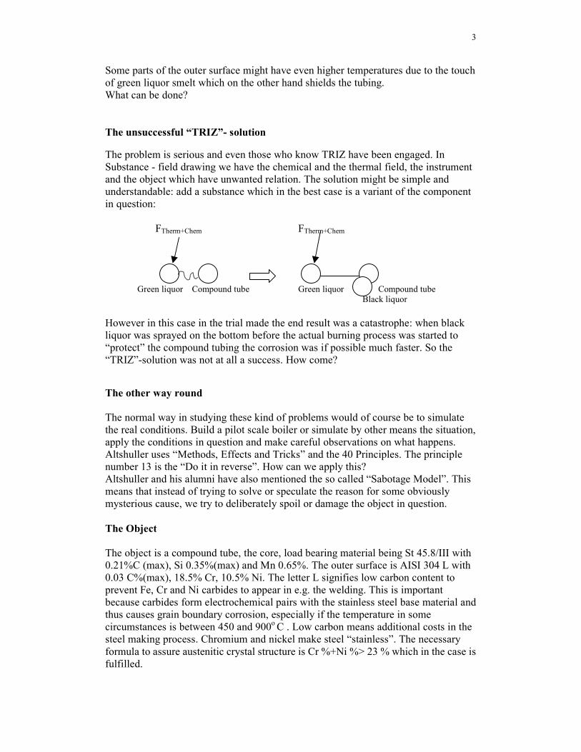
3
Some parts of the outer surface might have even higher temperatures due to the touch of green liquor smelt which on the other hand shields the tubing. What can be done? The unsuccessful “TRIZ”- solution The problem is serious and even those who know TRIZ have been engaged. In Substance - field drawing we have the chemical and the thermal field, the instrument and the object which have unwanted relation. The solution might be simple and understandable: add a substance which in the best case is a variant of the component in question: FTherm+Chem FTherm+Chem Green liquor Compound tube Green liquor Compound tube Black liquor However in this case in the trial made the end result was a catastrophe: when black liquor was sprayed on the bottom before the actual burning process was started to “protect” the compound tubing the corrosion was if possible much faster. So the “TRIZ”-solution was not at all a success. How come? The other way round The normal way in studying these kind of problems would of course be to simulate the real conditions. Build a pilot scale boiler or simulate by other means the situation, apply the conditions in question and make careful observations on what happens. Altshuller uses “Methods, Effects and Tricks” and the 40 Principles. The principle number 13 is the “Do it in reverse”. How can we apply this? Altshuller and his alumni have also mentioned the so called “Sabotage Model”. This means that instead of trying to solve or speculate the reason for some obviously mysterious cause, we try to deliberately spoil or damage the object in question. The Object The object is a compound tube, the core, load bearing material being St 45.8/III with 0.21%C (max), Si 0.35%(max) and Mn 0.65%. The outer surface is AISI 304 L with 0.03 C%(max), 18.5% Cr, 10.5% Ni. The letter L signifies low carbon content to prevent Fe, Cr and Ni carbides to appear in e.g. the welding. This is important because carbides form electrochemical pairs with the stainless steel base material and thus causes grain boundary corrosion, especially if the temperature in some circumstances is between 450 and 900o C . Low carbon means additional costs in the steel making process. Chromium and nickel make steel “stainless”. The necessary formula to assure austenitic crystal structure is Cr %+Ni %> 23 % which in the case is fulfilled.
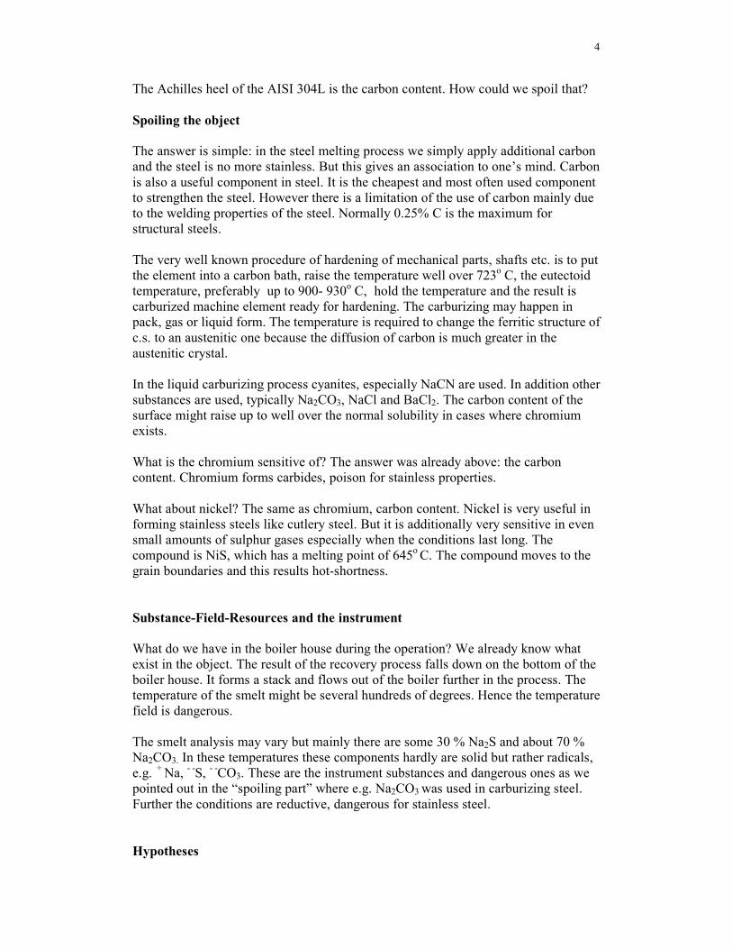
4
The Achilles heel of the AISI 304L is the carbon content. How could we spoil that? Spoiling the object The answer is simple: in the steel melting process we simply apply additional carbon and the steel is no more stainless. But this gives an association to one’s mind. Carbon is also a useful component in steel. It is the cheapest and most often used component to strengthen the steel. However there is a limitation of the use of carbon mainly due to the welding properties of the steel. Normally 0.25% C is the maximum for structural steels. The very well known procedure of hardening of mechanical parts, shafts etc. is to put the element into a carbon bath, raise the temperature well over 723o C, the eutectoid temperature, preferably up to 900- 930o C, hold the temperature and the result is carburized machine element ready for hardening. The carburizing may happen in pack, gas or liquid form. The temperature is required to change the ferritic structure of c.s. to an austenitic one because the diffusion of carbon is much greater in the austenitic crystal. In the liquid carburizing process cyanites, especially NaCN are used. In addition other substances are used, typically Na2CO3, NaCl and BaCl2. The carbon content of the surface might raise up to well over the normal solubility in cases where chromium exists. What is the chromium sensitive of? The answer was already above: the carbon content. Chromium forms carbides, poison for stainless properties. What about nickel? The same as chromium, carbon content. Nickel is very useful in forming stainless steels like cutlery steel. But it is additionally very sensitive in even small amounts of sulphur gases especially when the conditions last long. The compound is NiS, which has a melting point of 645o C. The compound moves to the grain boundaries and this results hot-shortness. Substance-Field-Resources and the instrument What do we have in the boiler house during the operation? We already know what exist in the object. The result of the recovery process falls down on the bottom of the boiler house. It forms a stack and flows out of the boiler further in the process. The temperature of the smelt might be several hundreds of degrees. Hence the temperature field is dangerous. The smelt analysis may vary but mainly there are some 30 % Na2S and about 70 % Na2CO3. In these temperatures these components hardly are solid but rather radicals, e.g. + Na, - -S, - -CO3. These are the instrument substances and dangerous ones as we pointed out in the “spoiling part” where e.g. Na2CO3 was used in carburizing steel. Further the conditions are reductive, dangerous for stainless steel. Hypotheses

5
The prevailing assumption of the cause is the stress corrosion. This might be the main mechanism although the stress should be in the first hand tensile stress not compression. On the other hand on the boiler walls, where the conditions are almost the same, such cracks as on the bottom part have not been reported. What differentiates the bottom from the wall? The answer is obvious: the touch of smelt. But the stress corrosion is not effective unless there are faults in the crystal structure. These are e.g. segregation all over the crystals due to carburizing conditions and thus precipitation in the grain boundaries are favourable in the temperature in question . We do not speak of some additional hundredths of percentage but rather up to several percentage of carbon content as pointed out by Kopietz under high carburizing conditions and especially when Cr exists. There are several possibilities in the process. Carbides (Fe, Cr, Ni)nCm are born, sulphides exist and all of these are unfavourable and you cant prevent them by additional components like molybdenium or niobium because the disturbing substances are renewable, the compound tube not. We have very favourable conditions for sabotage. All needed elements exist: the high temperature to boost carburizing conditions to form metal carbides, the sulphur to spoil nickel, the temperature to cause sensitiveness to grain boundary corrosion and perhaps the temperature to add hot-shortness of nickel-sulphide. What else could we need to spoil the tube? Yes, of course, 24h service, long lasting unfavourable conditions for even modest harmful elements. Long periods of normal production conditions are followed by shutdowns for maintenance, when temperature shocks might occur in cooling down the boiler for required maintenance conditions.. What can be done? Altshuller had 10 Standards to solve Substance-Field problems. None of these seems to apply. We know however that an excessive field is removed by a substance and an excessive material is removed by a field. In a Substance-Field drawing we should introduce in between a new substance to prevent the harmful chemical and thermal field and the elements not to touch each other. This could be an additional lining, like the one of electrolytic copper which is used to prevent carburizing in c.s. where hardening is not required or desired. But this will not perhaps apply as the s.s. part of the tube is already a lining. There would be lining above lining and no knowledge exists whether copper will last in these thermal and chemical conditions. An other possibility is brickwork. The last one is a very obvious solution and also used elsewhere in process industry. Further we might speculate that the problems is due to the austenitic structure of the compound steel (the diffusion or absorption of carbon is much faster and comprehensive into the austenitic steel than into ferritic). Thus a lot of carbides are segregated to the grain boundaries and form a net around the crystal. Further we ought to avoid nickel, which makes the structure austenitic and which is also sensitive to sulphur. The danger occurs when the temperature is lowered and the s.s. part of compound is due to tensile stress and the carbide nets will not hold but crack the material. The
6
carburizing conditions will produce and segregate carbide nets around the crystals and cause the cracks together with the sulphides and the tensile stress. The recommendation The recommendation is to give up from 18 % Cr, 10 % Ni low carbon compound tube and to replace the tube by either ferritic low carbon 30 % Cr-lining above c.s. tubing or 30 % Cr-compound tube at the bottom part of the boiler (Cr> 30 %, fire resistant, S-resistant, with Al and Si components or Mo). The Cr-lining could also be alloyed by small amounts of titanium, molybdenium or wolfram to compensate the harmful effect of chromium to the carbon content in the alloy’s ferritic crystal. However the existence of such commercially available compound tubes is not likely. The sheet might be available. The other possibility is to abandon the compound tubing and apply masonry above c.s. tubing to give thermal and chemical shield. Discussion The recommendations made above still leave questions to be answered. There exists even in the 30% Cr alloy possible problems. To mention but a few there are the so called 475o C and the sigma brittlenesses. The Cr content could be in the range of 14 to 30 %. The lower content requires low carbon content, the latter up allows up to 0.25 % C. But the danger still lurks for carburizing and carbides. Masonry has also pros and cons. The fire resistance is probably no problem, but the chemical properties of different kinds of mortar are not known to the author. The clear disadvantages are the on the site manufacturing process and the additional weight. Further one’s mind is occupied by the fact that there has not been found corrosive or other defects on the boiler walls, especially those related to sulphur gases. However, the unsuccessful trial with black liquor might prove the “carburizing” defect to be the main cause of the defects, because black liquor contains even more carbon than green liquor. Authors note The author is a Management Consultant holding the degree of Master of Engineering. Since my knowledge of structural metallurgy is almost 40 years of age the reader should understand that I am in fact a layman. The metallurgy is a very complicated science and all the resulting recommendation should of course be verified by actual tests before installation. However, with the “Sabotage Model” applied and the refresh of elementary metal physics in only a few days resulting maybe new ideas, might be enough to prove the power of the TRIZ. Any comments? [email protected]