triga z xtrem - spit xtrem · bolt : class 8.8 nf en 20898-1 ... e10-15/100 100 194 050694...
TRANSCRIPT
28
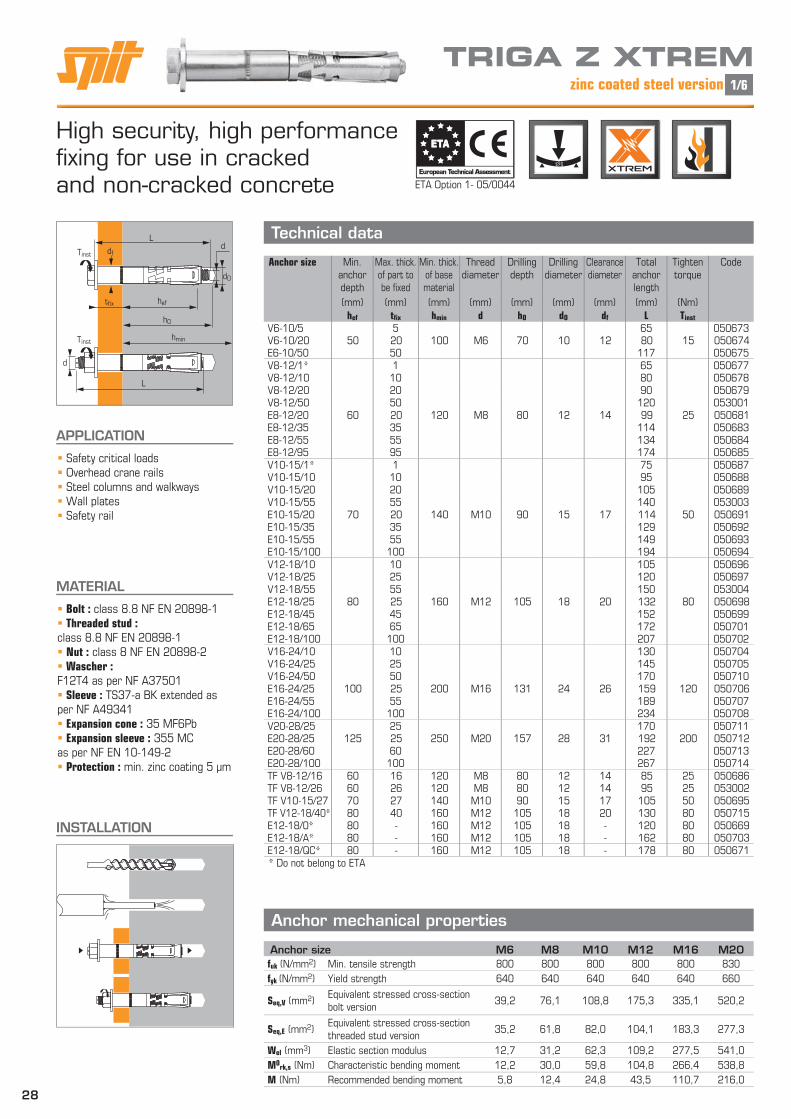
High security, high performance fi xing for use in cracked and non-cracked concrete
APPLICATION
Safety critical loads Overhead crane rails Steel columns and walkways Wall plates Safety rail
MATERIAL
Bolt : class 8.8 NF EN 20898-1 Threaded stud :class 8.8 NF EN 20898-1 Nut : class 8 NF EN 20898-2 Wascher : F12T4 as per NF A37501 Sleeve : TS37-a BK extended as per NF A49341 Expansion cone : 35 MF6Pb Expansion sleeve : 355 MC as per NF EN 10-149-2 Protection : min. zinc coating 5 μm
Anchor mechanical properties
Technical data
INSTALLATION
ETA Option 1- 05/0044
European Technical Assessment
ETAETA
TRIGA Z XTREMzinc coated steel version
Anchor size M6 M8 M10 M12 M16 M20fuk (N/mm2) Min. tensile strength 800 800 800 800 800 830
fyk (N/mm2) Yield strength 640 640 640 640 640 660
Seq,V (mm2) Equivalent stressed cross-section bolt version
39,2 76,1 108,8 175,3 335,1 520,2
Seq,E (mm2) Equivalent stressed cross-sectionthreaded stud version
35,2 61,8 82,0 104,1 183,3 277,3
Wel (mm3) Elastic section modulus 12,7 31,2 62,3 109,2 277,5 541,0
M0rk,s (Nm) Characteristic bending moment 12,2 30,0 59,8 104,8 266,4 538,8
M (Nm) Recommended bending moment 5,8 12,4 24,8 43,5 110,7 216,0
Anchor size Min. anchor depth
Max. thick. of part to be fixed
Min. thick. of base material
Threaddiameter
Drilling depth
Drilling diameter
Clearance diameter
Total anchor length
Tighten torque
Code
(mm) (mm) (mm) (mm) (mm) (mm) (mm) (mm) (Nm)hef tfix hmin d hO dO df L Tinst
V6-10/5 5 65 050673V6-10/20 50 20 100 M6 70 10 12 80 15 050674E6-10/50 50 117 050675V8-12/1* 1 65 050677V8-12/10 10 80 050678V8-12/20 20 90 050679V8-12/50 50 120 053001E8-12/20 60 20 120 M8 80 12 14 99 25 050681E8-12/35 35 114 050683E8-12/55 55 134 050684E8-12/95 95 174 050685V10-15/1* 1 75 050687V10-15/10 10 95 050688V10-15/20 20 105 050689V10-15/55 55 140 053003E10-15/20 70 20 140 M10 90 15 17 114 50 050691E10-15/35 35 129 050692E10-15/55 55 149 050693E10-15/100 100 194 050694V12-18/10 10 105 050696V12-18/25 25 120 050697V12-18/55 55 150 053004E12-18/25 80 25 160 M12 105 18 20 132 80 050698E12-18/45 45 152 050699E12-18/65 65 172 050701E12-18/100 100 207 050702V16-24/10 10 130 050704V16-24/25 25 145 050705V16-24/50 50 170 050710E16-24/25 100 25 200 M16 131 24 26 159 120 050706E16-24/55 55 189 050707E16-24/100 100 234 050708V20-28/25 25 170 050711E20-28/25 125 25 250 M20 157 28 31 192 200 050712E20-28/60 60 227 050713E20-28/100 100 267 050714TF V8-12/16 60 16 120 M8 80 12 14 85 25 050686TF V8-12/26 60 26 120 M8 80 12 14 95 25 053002TF V10-15/27 70 27 140 M10 90 15 17 105 50 050695TF V12-18/40* 80 40 160 M12 105 18 20 130 80 050715E12-18/0* 80 - 160 M12 105 18 - 120 80 050669E12-18/A* 80 - 160 M12 105 18 - 162 80 050703E12-18/QC* 80 - 160 M12 105 18 - 178 80 050671* Do not belong to ETA
d
L
L
d
d0
heftfix
dfTinst
Tinsthmin
h0
1/6

29
Ultimate (NRu,m, VRu,m) and characteristic loads (NRk, VRk) in kN Mean Ultimate loads are derived from test results in admissible service conditions, and characteristic loads are statistically determined.
TENSILE SHEAR
Design loads (NRd, VRd) for one anchor without edge or spacing influence in kN
TENSILE SHEAR
Recommended loads (Nrec, Vrec) for one anchor without edge or spacing influence in kN
TENSILE SHEAR
The loads specified on this page allow judging the product’s performances, but cannot be used for the designing.The data given in the pages “CC method” have to be applied (3/6 to 6/6).
54 12 30
Ø30E12-18/A
Ø12
Ø20E12-18/QC TF = countersunk head
Special products
90°24 for M827 for M1032 for M12
7,0 for M87,0 for M107,5 for M12Recommended loads in kN
Anchor size TENSILE ≥ C20/25 OBLIQUE ≥ C20/25 SHEAR ≥ C20/25
E12-18/A 3,42,4*
*(30≤ ≤45°) Not recommended
E12-18/QC 4,0 1,0 0,5
TF V8-12/16
The resistance given for the bolt version with the same diameter can be usedTF V8-12/26
TF V10-15/27
TF V12-18/40
TRIGA Z XTREMzinc coated steel version
Anchor size M6 M8 M10 M12 M16 M20Non-cracked concrete
hef 50 60 70 80 100 125
NRd 10,7 13,2 24,0 22,8 41,3 57,3
Cracked concrete
hef 50 60 70 80 100 125
NRd 7,7 9,9 17,7 24,4 47,0 60,1
Mc = 1,5
Anchor size M6 M8 M10 M12 M16 M20Cracked & non-cracked concrete
Type V/T VRu,m 29,2 41,7 68,0 95,7 159,0 228,2
VRk 25,9 38,6 58,8 83,3 141,6 206,0
Type E VRu,m 20,0 26,2 43,1 57,0 116,0 135,9
VRk 15,7 22,0 36,4 52,0 110,0 124,9
Anchor size M6 M8 M10 M12 M16 M20Non-cracked concrete
hef 50 60 70 80 100 125
NRu,m 18,2 27,5 45,9 54,4 103,6 124,4
NRk 16,0 19,9 36,0 34,2 61,9 85,9
Cracked concrete
hef 50 60 70 80 100 125
NRu,m 15,1 20,3 33,3 50,3 88,5 113,3
NRk 11,5 14,8 26,5 36,6 70,4 90,1
Anchor size M6 M8 M10 M12 M16 M20Non-cracked concrete
hef 50 60 70 80 100 125
Nrec 7,6 9,5 17,1 16,3 29,5 40,9
Cracked concrete
hef 50 60 70 80 100 125
Nrec 5,5 7,0 12,6 17,4 33,5 42,9
F= 1,4 ; Mc = 1,5
Anchor size M6 M8 M10 M12 M16 M20Cracked & non-cracked concrete
Type V/T VRd 20,7 30,8 47,0 66,6 113,3 164,8
Type E VRd 12,6 17,6 29,1 41,6 88,0 99,9
Ms = 1,25
Anchor size M6 M8 M10 M12 M16 M20Cracked & non-cracked concrete
Type V/T Vrec 14,8 22,0 33,6 47,6 80,9 117,7
Type E Vrec 9.0 12,5 20,8 29,7 62,9 71,4
F= 1,4 ; Ms = 1,25
2/6
*Derived from test resultsMc
NRk *NRd = Ms
VRk *VRd =
M F
NRk *Nrec = M F
VRk *Vrec =*Derived from test results
30
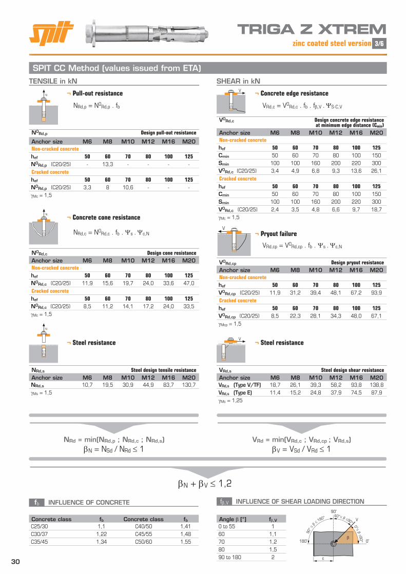
SPIT CC Method (values issued from ETA)TENSILE in kN SHEAR in kN
¬ Pull-out resistanceN
¬ Concrete cone resistanceN
¬ Pryout failureV
¬ Steel resistance
N
¬ Concrete edge resistance V
fb INFLUENCE OF CONCRETE
¬ Steel resistanceV
NRd = min(NRd,p ; NRd,c ; NRd,s)N = NSd / NRd 1
VRd = min(VRd,c ; VRd,cp ; VRd,s)V = VSd / VRd 1
N + V 1,2
β
V
90˚
180˚ 0˚
c
90°
≤ β ≤
180° 60°≤ β ≤90°
0°≤ β ≤60°
TRIGA Z XTREMzinc coated steel version
N0Rd,p Design pull-out resistance
Anchor size M6 M8 M10 M12 M16 M20Non-cracked concrete
hef 50 60 70 80 100 125
N0Rd,p (C20/25) - 13,3 - - - -
Cracked concrete
hef 50 60 70 80 100 125
N0Rd,p (C20/25) 3,3 8 10,6 - - -
Mc = 1,5
N0Rd,c Design cone resistance
Anchor size M6 M8 M10 M12 M16 M20Non-cracked concrete
hef 50 60 70 80 100 125
N0Rd,c (C20/25) 11,9 15,6 19,7 24,0 33,6 47,0
Cracked concrete
hef 50 60 70 80 100 125
N0Rd,c (C20/25) 8,5 11,2 14,1 17,2 24,0 33,5
Mc = 1,5
NRd,s Steel design tensile resistance
Anchor size M6 M8 M10 M12 M16 M20NRd,s 10,7 19,5 30,9 44,9 83,7 130,7
Ms = 1,5
Concrete class fb Concrete class fbC25/30 1,1 C40/50 1,41
C30/37 1,22 C45/55 1,48
C35/45 1,34 C50/60 1,55
V0Rd,c Design concrete edge resistance at minimum edge distance (Cmin)
Anchor size M6 M8 M10 M12 M16 M20Non-cracked concrete
hef 50 60 70 80 100 125
Cmin 50 60 70 80 100 150
Smin 100 100 160 200 220 300
V0Rd,c (C20/25) 3,4 4,9 6,8 9,3 13,6 26,1
Cracked concrete
hef 50 60 70 80 100 125
Cmin 50 60 70 80 100 150
Smin 100 100 160 200 220 300
V0Rd,c (C20/25) 2,4 3,5 4,8 6,6 9,7 18,7
Mc = 1,5
V0Rd,cp Design pryout resistance
Anchor size M6 M8 M10 M12 M16 M20Non-cracked concrete
hef 50 60 70 80 100 125
V0Rd,cp (C20/25) 11,9 31,2 39,4 48,1 67,2 93,9
Cracked concrete
hef 50 60 70 80 100 125
V0Rd,cp (C20/25) 8,5 22,3 28,1 34,3 48,0 67,1
Mcp = 1,5
VRd,s Steel design shear resistance
Anchor size M6 M8 M10 M12 M16 M20VRd,s (Type V/TF) 18,7 26,1 39,3 58,2 93,8 138,8
VRd,s (Type E) 11,4 15,2 24,8 37,9 74,5 87,9
Ms = 1,25
Angle [°] f,V0 to 55 1
60 1,1
70 1,2
80 1,5
90 to 180 2
3/6
NRd,p = N0Rd,p . fb
NRd,c = N0Rd,c . fb . s . c,N
VRd,c = V0Rd,c . fb . fV . S-C,V
VRd,cp = V0Rd,cp . fb . s . c,N
f,V INFLUENCE OF SHEAR LOADING DIRECTION

31
s INFLUENCE OF SPACING FOR CONCRETE CONE RESISTANCE IN TENSILE LOAD
c,N INFLUENCE OF EDGE FOR CONCRETE CONE RESISTANCE IN TENSILE LOAD
s-c,V INFLUENCE OF SPACING AND EDGE DISTANCE FOR CONCRETE EDGE RESISTANCE IN SHEAR LOAD
¬ For 2 anchors fastening
¬ For 3 anchors fastening and more
N
c
s
N
V
h>1,5.c
s
V
h>1,5.c
¬ For single anchor fastening
SPIT CC Method (values issued from ETA)
s1
V
s2 s3
sn-1
h>1,5.c
TRIGA Z XTREMzinc coated steel version
SPACING S Reduction factor s
Cracked & non-cracked concrete
Anchor size M6 M8 M10 M12 M16 M2050 0,67
60 0,70 0,67
70 0,73 0,69 0,67
80 0,77 0,72 0,69 0,67
100 0,83 0,78 0,74 0,71 0,67
125 0,92 0,85 0,80 0,76 0,71 0,67
150 1,00 0,92 0,86 0,81 0,75 0,70
180 1,00 0,93 0,88 0,80 0,74
210 1,00 0,94 0,85 0,78
240 1,00 0,90 0,82
300 1,00 0,90
375 1,00
EDGE C Reduction factor c,N
Cracked & non-cracked concrete
Anchor size M6 M8 M10 M12 M16 M2050 0,75
60 0,85 0,75
70 0,95 0,83 0,75
80 1,00 0,92 0,82 0,75
90 1,00 0,89 0,81
100 0,96 0,88 0,75
120 1,00 0,85
150 1,00 0,85
170 0,93
190 1,00
Reduction factor s-c,V
Cracked & non-cracked concrete
1,0 1,2 1,4 1,6 1,8 2,0 2,2 2,4 2,6 2,8 3,0 3,2
1,0 0,67 0,84 1,03 1,22 1,43 1,65 1,88 2,12 2,36 2,62 2,89 3,16
1,5 0,75 0,93 1,12 1,33 1,54 1,77 2,00 2,25 2,50 2,76 3,03 3,31
2,0 0,83 1,02 1,22 1,43 1,65 1,89 2,12 2,38 2,63 2,90 3,18 3,46
2,5 0,92 1,11 1,32 1,54 1,77 2,00 2,25 2,50 2,77 3,04 3,32 3,61
3,0 1,00 1,20 1,42 1,64 1,88 2,12 2,37 2,63 2,90 3,18 3,46 3,76
3,5 1,30 1,52 1,75 1,99 2,24 2,50 2,76 3,04 3,32 3,61 3,91
4,0 1,62 1,86 2,10 2,36 2,62 2,89 3,17 3,46 3,75 4,05
4,5 1,96 2,21 2,47 2,74 3,02 3,31 3,60 3,90 4,20
5,0 2,33 2,59 2,87 3,15 3,44 3,74 4,04 4,35
5,5 2,71 2,99 3,28 3,71 4,02 4,33 4,65
6,0 2,83 3,11 3,41 3,71 4,02 4,33 4,65
Cmin
C
Cmin
S
Reduction factor s-c,V
Cracked & non-cracked concrete
1,0 1,2 1,4 1,6 1,8 2,0 2,2 2,4 2,6 2,8 3,0 3,2
s-c,V 1,00 1,31 1,66 2,02 2,41 2,83 3,26 3,72 4,19 4,69 5,20 5,72
Cmin
C
4/6
c,N = 0,25 + 0,5 . c
hef
s = 0,5 + s
6.hef
s-c,V = c
. c
cmin cmin
s-c,V = 3.c + s
. c
6.cmin cmin
s-c,V = 3.c + s1 + s2 + s3 +....+ sn-1 .
c 3.n.cmin cmin
smin < s < scr,N
scr,N = 3.hef
S must be used for each spacing influenced the anchors group.
cmin < c < ccr,N
ccr,N = 1,5.hef
c,N must be used for each distance influenced the anchors group.
32
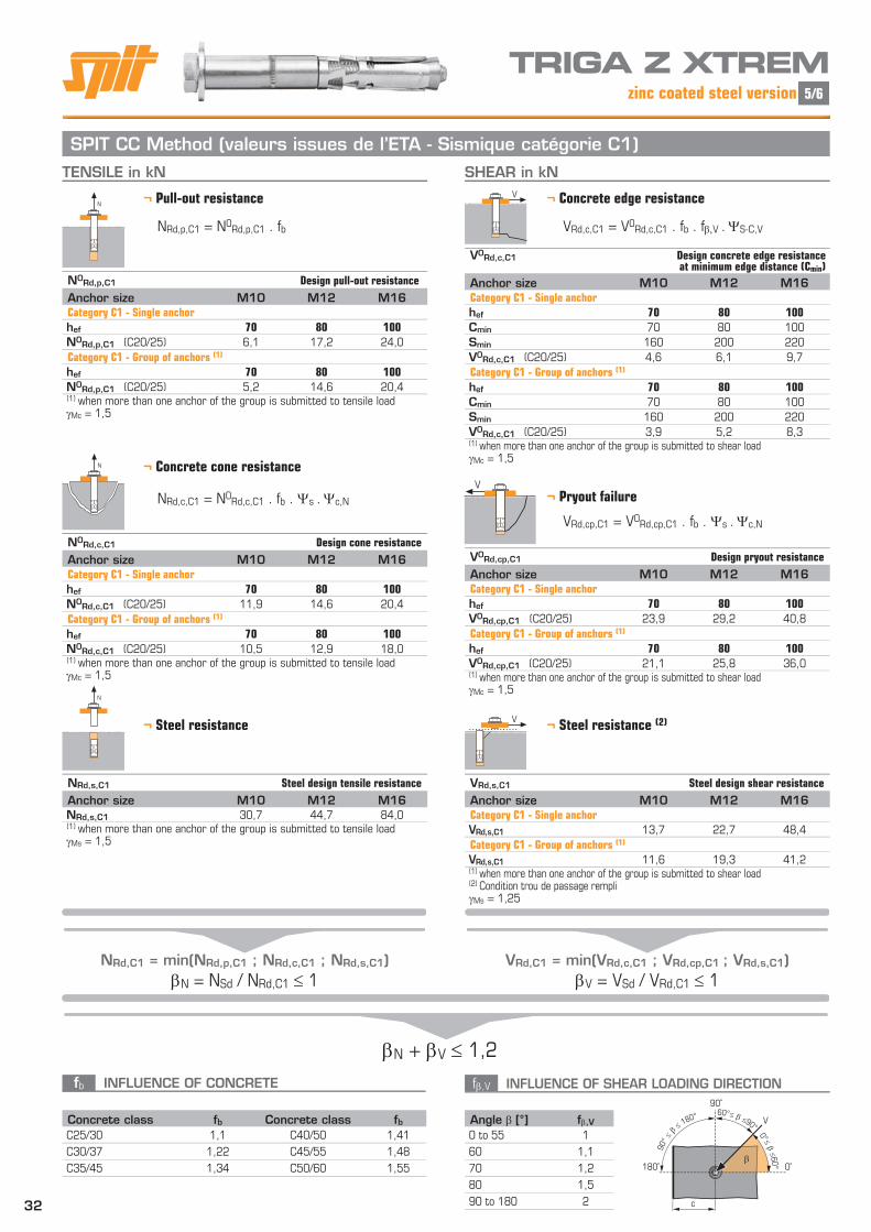
SPIT CC Method (valeurs issues de l’ETA - Sismique catégorie C1)TENSILE in kN SHEAR in kN
¬ Pull-out resistanceN
¬ Concrete cone resistanceN
¬ Pryout failureV
¬ Steel resistance
N
¬ Concrete edge resistance V
fb INFLUENCE OF CONCRETE
¬ Steel resistance (2)V
NRd,C1 = min(NRd,p,C1 ; NRd,c,C1 ; NRd,s,C1)N = NSd / NRd,C1 1
VRd,C1 = min(VRd,c,C1 ; VRd,cp,C1 ; VRd,s,C1)V = VSd / VRd,C1 1
N + V 1,2
β
V
90˚
180˚ 0˚
c
90°
≤ β ≤
180° 60°≤ β ≤90°
0°≤ β ≤60°
TRIGA Z XTREMzinc coated steel version
N0Rd,p,C1 Design pull-out resistance
Anchor size M10 M12 M16Category C1 - Single anchorhef 70 80 100
N0Rd,p,C1 (C20/25) 6,1 17,2 24,0
Category C1 - Group of anchors (1)
hef 70 80 100
N0Rd,p,C1 (C20/25) 5,2 14,6 20,4(1) when more than one anchor of the group is submitted to tensile loadMc = 1,5
N0Rd,c,C1 Design cone resistance
Anchor size M10 M12 M16Category C1 - Single anchorhef 70 80 100
N0Rd,c,C1 (C20/25) 11,9 14,6 20,4
Category C1 - Group of anchors (1)
hef 70 80 100
N0Rd,c,C1 (C20/25) 10,5 12,9 18,0(1) when more than one anchor of the group is submitted to tensile loadMc = 1,5
NRd,s,C1 Steel design tensile resistance
Anchor size M10 M12 M16NRd,s,C1 30,7 44,7 84,0(1) when more than one anchor of the group is submitted to tensile loadMs = 1,5
Concrete class fb Concrete class fbC25/30 1,1 C40/50 1,41
C30/37 1,22 C45/55 1,48
C35/45 1,34 C50/60 1,55
V0Rd,c,C1 Design concrete edge resistance at minimum edge distance (Cmin)
Anchor size M10 M12 M16Category C1 - Single anchorhef 70 80 100
Cmin 70 80 100
Smin 160 200 220
V0Rd,c,C1 (C20/25) 4,6 6,1 9,7
Category C1 - Group of anchors (1)
hef 70 80 100
Cmin 70 80 100
Smin 160 200 220
V0Rd,c,C1 (C20/25) 3,9 5,2 8,3(1) when more than one anchor of the group is submitted to shear loadMc = 1,5
V0Rd,cp,C1 Design pryout resistance
Anchor size M10 M12 M16Category C1 - Single anchorhef 70 80 100
V0Rd,cp,C1 (C20/25) 23,9 29,2 40,8
Category C1 - Group of anchors (1)
hef 70 80 100
V0Rd,cp,C1 (C20/25) 21,1 25,8 36,0(1) when more than one anchor of the group is submitted to shear loadMc = 1,5
VRd,s,C1 Steel design shear resistance
Anchor size M10 M12 M16Category C1 - Single anchorVRd,s,C1 13,7 22,7 48,4
Category C1 - Group of anchors (1)
VRd,s,C1 11,6 19,3 41,2(1) when more than one anchor of the group is submitted to shear load(2) Condition trou de passage rempliMs = 1,25
Angle [°] f,V0 to 55 1
60 1,1
70 1,2
80 1,5
90 to 180 2
5/6
NRd,p,C1 = N0Rd,p,C1 . fb
NRd,c,C1 = N0Rd,c,C1 . fb . s . c,N
VRd,c,C1 = V0Rd,c,C1 . fb . fV . S-C,V
VRd,cp,C1 = V0Rd,cp,C1 . fb . s . c,N
f,V INFLUENCE OF SHEAR LOADING DIRECTION

33
SPIT CC Method (valeurs issues de l’ETA - Sismique catégorie C2)
TRIGA Z XTREMzinc coated steel version 6/6
TENSILE in kN SHEAR in kN
¬ Pull-out resistanceN
¬ Concrete cone resistanceN
¬ Pryout failureV
¬ Steel resistance
N
¬ Concrete edge resistance V
fb INFLUENCE OF CONCRETE
¬ Steel resistance (2)V
NRd,C2 = min(NRd,p,C2 ; NRd,c,C2 ; NRd,s,C2)N = NSd / NRd,C2 1
VRd,C2 = min(VRd,c,C2 ; VRd,cp,C2 ; VRd,s,C2)V = VSd / VRd,C2 1
N + V 1,2
β
V
90˚
180˚ 0˚
c
90°
≤ β ≤
180° 60°≤ β ≤90°
0°≤ β ≤60°
N0Rd,p,C2 Design pull-out resistance
Anchor size M10 M12 M16Category C2 - Single anchorhef 70 80 100
N0Rd,p,C2 (C20/25) 3,5 6,3 11,0
Category C2 - Group of anchors (1)
hef 70 80 100
N0Rd,p,C2 (C20/25) 3,0 5,3 9,4(1) when more than one anchor of the group is submitted to tensile loadMc = 1,5
N0Rd,c,C2 Design cone resistance
Anchor size M10 M12 M16Category C2 - Single anchorhef 70 80 100
N0Rd,c,C2 (C20/25) 9,5 11,9 16,0
Category C2 - Group of anchors (1)
hef 70 80 100
N0Rd,c,C2 (C20/25) 8,4 10,5 14,1(1) when more than one anchor of the group is submitted to tensile loadMc = 1,5
NRd,s,C2 Steel design tensile resistance
Anchor size M10 M12 M16NRd,s,C2 30,7 44,7 84,0(1) when more than one anchor of the group is submitted to tensile loadMs = 1,5
Concrete class fb Concrete class fbC25/30 1,1 C40/50 1,41
C30/37 1,22 C45/55 1,48
C35/45 1,34 C50/60 1,55
V0Rd,c,C2 Design concrete edge resistance at minimum edge distance (Cmin)
Anchor size M10 M12 M16Category C2 - Single anchorhef 70 80 100
Cmin 65 100 100
Smin 50 100 100
V0Rd,c,C2 (C20/25) 4,0 5,3 8,4
Category C2 - Group of anchors (1)
hef 70 80 100
Cmin 70 80 100
Smin 50 100 100
V0Rd,c,C2 (C20/25) 3,4 4,5 7,1(1) when more than one anchor of the group is submitted to shear loadMc = 1,5
V0Rd,cp,C2 Design pryout resistance
Anchor size M10 M12 M16Category C2 - Single anchorhef 70 80 100
V0Rd,cp,C2 (C20/25) 19,0 23,9 32,0
Category C2 - Group of anchors (1)
hef 70 80 100
V0Rd,cp,C2 (C20/25) 16,7 21,1 28,2(1) when more than one anchor of the group is submitted to shear loadMc = 1,5
VRd,s,C2 Steel design shear resistance
Anchor size M10 M12 M16Category C2 - Single anchorVRd,s,C2 11,6 22,7 46,5
Category C2 - Group of anchors (1)
VRd,s,C2 9,9 19,3 39,5(1) when more than one anchor of the group is submitted to shear load(2) In case of no hole clearance between anchor and fixtureMs = 1,25
Angle [°] f,V0 to 55 1
60 1,1
70 1,2
80 1,5
90 to 180 2
NRd,p,C2 = N0Rd,p,C2 . fb
NRd,c,C2 = N0Rd,c,C2 . fb . s . c,N
VRd,c,C2 = V0Rd,c,C2 . fb . fV . S-C,V
VRd,cp,C2 = V0Rd,cp,C2 . fb . s . c,N
f,V INFLUENCE OF SHEAR LOADING DIRECTION