treaty points and costing guidance
DESCRIPTION
Treaty Points and Costing Guidance. Nick Walker 1 st System Area Managers Meeting KEK – 19.01.2006. Introduction. Review the system boundaries outlined in this document Iterate and discuss agree on boundaries Discuss costing guidelines. The Baseline Machine (500GeV). ~30 km. - PowerPoint PPT PresentationTRANSCRIPT

Nick Walker – SA meeting KEK 19.01.06
Treaty Points andTreaty Points andCosting GuidanceCosting Guidance
Nick Walker1st System Area Managers Meeting
KEK – 19.01.2006

Nick Walker – SA meeting KEK 19.01.06
IntroductionIntroduction
• Review the system boundaries outlined in this document• Iterate and discuss• agree on boundaries• Discuss costing guidelines

Nick Walker – SA meeting KEK 19.01.06
The Baseline Machine (500GeV)The Baseline Machine (500GeV)
not to scale
~30 km
e+ undulator @ 150 GeV (~1.2km)x2R = 955m
E = 5 GeV
RTML ~1.6km
ML ~10km (G = 31.5MV/m)20mr
2mrBDS 5km

Nick Walker – SA meeting KEK 19.01.06
RDR MatrixRDR Matrix

Nick Walker – SA meeting KEK 19.01.06
RDR MatrixRDR Matrix
System Areas
Geographical breakdown of machine
Primary responsibility for design and ‘ownership of costs’

Nick Walker – SA meeting KEK 19.01.06
RDR MatrixRDR Matrix
Technical Systems
Your ‘Engineering & Cost’ resources
Responsible for engineering designing and costing of components in area systems
A point of contact will be identified for each tech. area to each system area

Nick Walker – SA meeting KEK 19.01.06
RDR MatrixRDR Matrix
Global Systems
Responsible for the more global aspects of the machine which do not specifically relate to a single system area or technical group
Nick Walker – SA meeting KEK 19.01.06
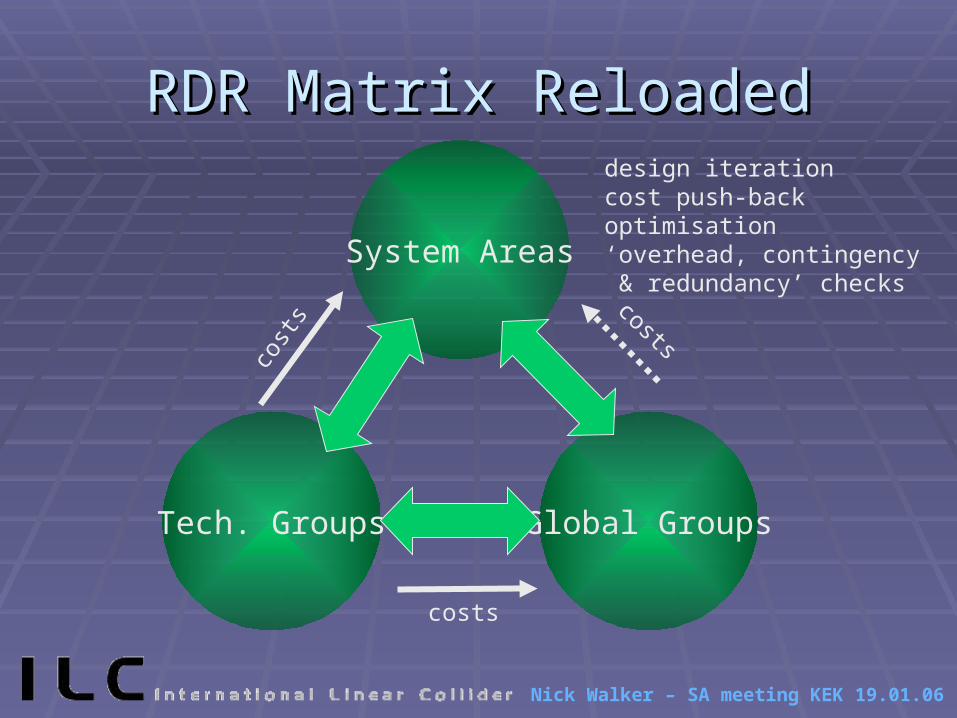
RDR Matrix ReloadedRDR Matrix Reloaded
System Areas
Tech. Groups Global Groups
design iterationcost push-backoptimisation‘overhead, contingency & redundancy’ checks
cost
s
costs
costs

Nick Walker – SA meeting KEK 19.01.06
Boundaries (Treaty Points)Boundaries (Treaty Points)
e- source e+ source DR RTML Main Linac BDS

Nick Walker – SA meeting KEK 19.01.06
Boundaries (Treaty Points)Boundaries (Treaty Points)
e- source e+ source DR RTML Main Linac BDS
Polarised electron gun (including laser system)
capture/bunching system/pre-acceleration
acceleration to 5 GeV
spin rotation
collimation
up to (but not including) DR injection
e- gun on positron system also included(up to dipole before 5 GeV linac)

Nick Walker – SA meeting KEK 19.01.06
Boundaries (Treaty Points)Boundaries (Treaty Points)
e- source e+ source DR RTML Main Linac BDS
All beamline components integrated with main ring vacuum system
Associated ancillary systems (power supplies, RF, etc.)
For stacked e+ ring, includes bunch combining/separation systems

Nick Walker – SA meeting KEK 19.01.06
Boundaries (Treaty Points)Boundaries (Treaty Points)
e- source e+ source DR RTML Main Linac BDS
Begins after DR extraction system and compensating bends
Ends at entrance to first Main Linac cryomodule

Nick Walker – SA meeting KEK 19.01.06
Boundaries (Treaty Points)Boundaries (Treaty Points)
e- source e+ source DR RTML Main Linac BDS
Begins with first cryomodule after RTML
Ends with last cryomodule before BDS
In addition to basic RF units, includes any warm insertions (diagnostics stations, MPS systems etc.)
problem area: e+ source in e- linac

Nick Walker – SA meeting KEK 19.01.06
Boundaries (Treaty Points)Boundaries (Treaty Points)
e- source e+ source DR RTML Main Linac BDS
Begins at exit of last cryomodule in Main Linac
Ends at (and includes) main beam dumps

Nick Walker – SA meeting KEK 19.01.06
Boundaries (Treaty Points)Boundaries (Treaty Points)
e- source e+ source DR RTML Main Linac BDS
Target system dumpCapture systempre-acceleration(long) transfer line5 GeV injection linacup to DR injection
undulator systeme- bypass systempre-undulator collimation (MPS)pre-undulator FEX (MPS)
clear responsibility of e+ source group
could be considered part of ML

Nick Walker – SA meeting KEK 19.01.06
Costing GuidelinesCosting Guidelines
The RDR is not a complete Technical/Engineering Design a design made to the level required to support a
reliable cost estimate
Good common sense has to be applied to level of engineering/costing Main Linac, CF&S
cost drivers: pay attention to details Injectors, DRs, BDS
not cost drivers: can make looser cost estimates

Nick Walker – SA meeting KEK 19.01.06
Example: US studyExample: US studynote: US accountingfull-cost model
CF&S included for each system

Nick Walker – SA meeting KEK 19.01.06
Example: US studyExample: US studynote: US accountingfull-cost model
CF&S included for each system
Orthogonal view (technical groups)

Nick Walker – SA meeting KEK 19.01.06
Cost Drivers: SCRF tech.Cost Drivers: SCRF tech.
bottom-up cost detailed cost estimate based on existing information (TDR, USLCOS) new input from industrial studies (US?) (XFEL TDR cost update)
May have largest uncertainty International agreed upon model for
costing SCRF tech. needed

Nick Walker – SA meeting KEK 19.01.06
Cost Drivers: CF&SCost Drivers: CF&S Civil engineering requirements must be well specified
tunnel diameters, lengths # of shafts, access etc PPS zones shielding requirements for hi rad areas etc. surface building requirements (space!)
scaling from existing machines or similar engineering projects useful
site dependencies may exist Must have a clear picture of what you want to go into a
tunnel, shaft, hall or building

Nick Walker – SA meeting KEK 19.01.06
Cost Drivers: CF&SCost Drivers: CF&S
Cooling & AC power requirements input needed from AS on
magnets, power supplies, electronic racks, klystrons/modulators etc.
some can be scaled from existing infrastructures
Special case: cryogenics look to LHC…

Nick Walker – SA meeting KEK 19.01.06
Non Cost DriversNon Cost Drivers
Careful: taken together still ¼-1/3 of total cost magnets: rough estimates of IV parameters, cooling
requirements needed based on field specs from AS No need to perform detailed magnet design
~30% best guess ~2% TPC
(warm) vacuum systems: rough design; scale from existing machines
controls (inc. software), instrumentation… rough counts, scale from existing experience

Nick Walker – SA meeting KEK 19.01.06
An Example:An Example:
example taken from USLCOS
estimating error TPC impact on TPCinstrumentation 30% 2% 1%ops 30% 4% 1%cryo 30% 4% 1%controls 30% 4% 1%vacuum 30% 4% 1%magnets 30% 6% 2%install. & test 20% 7% 1%syst. eng. 20% 8% 2%RF 10% 12% 1%cavities 20% 18% 4%CF 10% 31% 3%
100% 18%

Nick Walker – SA meeting KEK 19.01.06
WBS [PBS?]WBS [PBS?]
WBS is needed to define the level of cost detail required
First-pass at WBS (level of detail) can be made from experience
Will need to iterate as costs begin to arrive Our first job! Define the WBS

Nick Walker – SA meeting KEK 19.01.06
WBS using SLAC toolWBS using SLAC tool